
FATAL1TY-AN8-SLI - Motherboard ABIT - Free user manual and instructions
Find the device manual for free FATAL1TY-AN8-SLI ABIT in PDF.

| Product type | Motherboard |
| Brand | ABIT |
| Model | FATAL1TY-AN8-SLI |
| Form factor | ATX (305 x 245 mm) |
| CPU Socket | Socket 939 |
| Supported processors | Athlon 64 / 64FX (939 pins) |
| Chipset | NVIDIA nForce4 SLI |
| Memory | 4 x DDR DIMM, up to 4 GB, DDR400/333/266 non-ECC |
| Expansion slots | 2 x PCI-E x16 (SLI), 2 x PCI-E x1, 2 x PCI |
| Storage | 2 x Ultra DMA 133, 4 x SATA 3 Gb/s (RAID 0/1/0+1) |
| Audio | AudioMAX 7.1 channel daughterboard, optical S/PDIF in/out |
| Network | NVIDIA Gigabit Ethernet with integrated firewall |
| USB ports | 4 USB 2.0 ports at rear, 3 headers for 6 additional ports |
| IEEE1394 (FireWire) | 1 rear port, 1 header |
| Power requirement | ATX 24-pin + 12V 4-pin + aux 12V 4-pin (min 350W, 20A on +5V) |
| Special features | ABIT uGuru, OTES, AudioMAX, CPU ThermalGuard, SLI, Cool'n'Quiet |
| Dimensions | 305 mm x 245 mm |
| Approximate weight | 0.8 kg |
| Maintenance | Dust regularly, avoid humidity, do not touch circuits |
| Safety | Discharge static electricity before handling, cut power |
Frequently Asked Questions - FATAL1TY-AN8-SLI ABIT
User questions about FATAL1TY-AN8-SLI ABIT
0 question about this device. Answer the ones you know or ask your own.
Ask a new question about this device
Download the instructions for your Motherboard in PDF format for free! Find your manual FATAL1TY-AN8-SLI - ABIT and take your electronic device back in hand. On this page are published all the documents necessary for the use of your device. FATAL1TY-AN8-SLI by ABIT.
USER MANUAL FATAL1TY-AN8-SLI ABIT
Socket 939 System Board
User's Manual
For more information:
WWW.ABIT.COM.TW
WWW.FATALITY.COM
4200-0453-03
Rev. 1.01
Copyright and Warranty Notice
The information in this document is subject to change without notice and does not represent a commitment on part of the vendor, who assumes no liability or responsibility for any errors that may appear in this manual.
No warranty or representation, either expressed or implied, is made with respect to the quality, accuracy or fitness for any particular part of this document. In no event shall the manufacturer be liable for direct, indirect, special, incidental or consequential damages arising from any defect or error in this manual or product.
Product names appearing in this manual are for identification purpose only and trademarks and product names or brand names appearing in this document are the property of their respective owners.
This document contains materials protected under International Copyright Laws. All rights reserved. No part of this manual may be reproduced, transmitted or transcribed without the expressed written permission of the manufacturer and authors of this manual.
If you do not properly set the motherboard settings, causing the motherboard to malfunction or fail, we cannot guarantee any responsibility.
The Fatal1ty name, Fatal1ty logos and the Fatal1ty likeness are trademarks of Fatal1ty, Inc. All rights reserved. Built to Kill is a trademark of PWX, LLC.
© 2005 ABIT Computer Corporation.
All other trademarks are the property of their respective owners.
Table of Contents
Chapter 1. Introduction 1-1
1-1. Fatality. 1-1
1-2. Features & Specifications 1-3
1-3. Layout Diagram 1-5
Chapter 2. Hardware Setup 2-1
2-1. Install The Motherboard 2-1
2-2. Install CPU, Heatsink and Fan Assembly 2-2
2-3. Install System Memory 2-4
2-4. Install two Graphics Cards with NVIDIA SLI Technology 2-6
2-5. Connectors, Headers and Switches 2-9
(1).ATX Power Input Connectors 2-9
(2). FAN Power Connectors 2-10
(3). CMOS Memory Clearing Header 2-11
(4). Front Panel Switches & Indicators Headers 2-12
(5). Additional USB Port Headers 2-13
(6). Additional IEEE1394 Port Headers 2-13
(7). Wake-up Header 2-14
(8). GURU Panel Connection Header 2-15
(9). Floppy and IDE Disk Drive Connectors 2-16
(10). Serial ATA Connectors 2-17
(11). Status Indicators 2-18
(12). POST Code Display 2-19
(13). PCI Express x1 Slots 2-20
(14). PCI Express x16 Slot 2-21
(15). SLI Switchboard Slot. 2-22
(16).AUDIOMAX Slot. 2-23
(17).Front Panel Audio Connection Header 2-29
(18). Internal Audio Connectors 2-30
(19). Back Panel Connectors 2-31
Chapter 3. BIOS Setup 3-1
3-1. Guru^TM Utility 3-2
3-2. Standard CMOS Features 3-10
3-3. Advanced BIOS Features 3-13
3-4. Advanced Chipset Features 3-15
3-5. Integrated Peripherals 3-18
3-6. Power Management Setup 3-23
3-7. PnP/PCI Configurations 3-25
3-8. Load Fail-Safe Defaults 3-27
3-9. Load Optimized Defaults 3-27
3-10. Set Password 3-27
3-11. Save & Exit Setup 3-27
3-12. Exit Without Saving 3-27
Appendix A. Install nVidia nForce Chipset Driver
Appendix B. Install Realtek Audio Driver. B-1
Appendix C. Install USB 2.0 Driver..
Appendix D. Install AMD64 Processor Driver. 1
Appendix E. Install ABIT μGuru Utility
Appendix F. AN8 NVRaid Floppy Disk
Appendix G. POST Code Definition.. .G-1
Appendix H. Troubleshooting (Need Assistance?).. H-1
Appendix I. How to Get Technical Support. 1-1
For more information:
WWW.ABIT.COM.TW
WWW.FATALITY.COM
Chapter 1. Introduction
1-1. Fatality
FATALITY STORY
Who knew that at age 19, I would be a World Champion PC gamer. When I was 13, I actually played competitive billiards in professional tournaments and won four or five games off guys who played at the highest level. I actually thought of making a career of it, but at that young age situations change rapidly. Because I've been blessed with great hand-eye coordination and a grasp of mathematics (an important element in video gaming) I gravitated to that activity.

GOING PRO
I started professional gaming in 1999 when I entered the CPL (Cyberathlete Professional League) tournament in Dallas and won 4,000 for coming in third place. Emerging as one of the top players in the United States, a company interested in sponsoring me flew me to Sweden to compete against the top 12 players in the world. I won 18 straight games, lost none, and took first place, becoming the number one ranked Quake III player in the world in the process. Two months later I followed that success by traveling to Dallas and defending my title as the world's best Quake III player, winning the40,000 grand prize. My earned frags allowed at this tournament were 2.5. From there I entered competitions all over the world, including Singapore, Korea, Germany, Australia, Holland and Brazil in addition to Los Angeles, New York and St. Louis.
WINNING STREAK
I was excited to showcase my true gaming skills when defending my title as CPL Champion of the year at the CPL Winter 2001 because I would be competing in a totally different first person shooter (fps) game, Alien vs. Predator II. I won that competition and walked away with a new car. The next year I won the same title playing Unreal Tournament 2003, becoming the only three-time CPL champion. And I did it playing a different game each year, something no one else has ever done and a feat of which I am extremely proud.
At QuakeCon 2002, I faced off against my rival ZeRo4 in one of the most highly anticipated matches of the year, winning in a 14 to (-1) killer victory. Competing at Quakecon 2004, I became the World's 1^st Doom3 Champion by defeating Daler in a series of very challenging matches and earning $25,000 for the victory.
LIVIN' LARGE
Since my first big tournament wins, I have been a "Professional Cyberathlete", traveling the world and livin' large with lots of International media coverage on outlets such as MTV, ESPN and G4TV to name only a few. It's unreal - it's crazy. I'm living a dream by playing video games for a living. I've always been athletic and took sports like hockey and football very seriously, working out and training hard. This discipline helps me become a better gamer and my drive to be the best has opened the doors necessary to become a professional.
ADREAM
Now, another dream is being realized - building the ultimate gaming computer, made up of the best parts under my own brand. Quality hardware makes a huge difference in competitions...a couple more frames per second and everything gets really nice. It's all about getting the computer processing faster and allowing more fluid movement around the maps.
My vision for Fatality hardware is to allow gamers to focus on the game without worrying about their equipment, something I've preached since I began competing. I don't want to worry about my equipment. I want it to be there - over and done with - so I can focus on the game. I want it to be the fastest and most stable computer equipment on the face of the planet, so quality is what Fatality brand products will represent.
FATALITY BRAIN TRUST
This is just the beginning. We're already in development for several new products, including high-level Fatality – PwX systems for next year, and I'm really grateful to all my Fatality Brain Trust partners for helping make my dreams a reality.
I know there is a business side to all of this, but for me the true reward is making products that are so good I can win with them – and making them available to fellow gamers. Gaming is my life, and many fellow gamers around the world are also some of my best friends, so giving back to the gaming community is really important to me.

Johnathan "Fatality" Wendel
1-2. Features & Specifications
1. CPU
Supports AMD Athlon 64/64FX 939-pin K8 CPU with 2GHz system bus using Hyper Transport Technology
Supports AMD CPU Cool 'n' Quiet Technology
2. Chipset
NVIDIA nForce4 SLI single chip
- Integrated NVIDIA Gigabit Ethernet and NVIDIA Firewall
3. NVIDIA SLI Technology
- Two PCI-Express X16 slots support NVIDIA Scalable Link Interface
- Increase bandwidth of the PCI Express™ bus providing 60x the bandwidth of PCI
4. Memory
Four 184-pin DIMM sockets
Supports 4 DIMM Dual DDR 400/333/266 non-ECC un-buffered memory
Supports maximum memory capacity up to 4GB
5. ABIT Engineered
- ABIT uGuru™ 2003 Technology
- ABIT OTES™ Technology
- ABIT AudioMAX™ Technology
- ABIT CPU ThermalGuard™ Technology
6. NV SATA RAID
Supports SATA 3Gbps data transfer rate
Supports SATA RAID 0 / 1 / 0 + 1
7. NV GbE LAN
NVIDIA Gigabit Ethernet Controller
NVIDIA Secure Networking Engine
8. NV Firewall
- Native NVIDIA Firewall
9.IEEE1394
Supports IEEE 1394 at 100 / 200 / 400Mb / s transfer rate
10. Audio
High quality 7.1-channel Audio Card
Optical S/P DIF In/Out
Supports auto jack sensing
11. Internal I/O Connectors
2x PCI-E X16 slot
2x PCI-E X1 slots
2x PCI slots
1x Audio daughter card port
1x Floppy port supports up to 2.88MB
2x Ultra DMA 133/100/66/33 IDE connectors
4x SATA 3G connectors
- 3x USB headers
- 1x IEEE 1394 header
12. Back Panel I/O
1x IEEE 1394 Connector
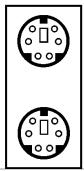
1x PS/2 keyboard, 1x PS/2 mouse
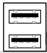
4x USB, 1x RJ-45 LAN Connector
1x Dual OTES
13. Miscellaneous
ATX form factor: 305 × 245 ~mm
- Specifications and information contained herein are subject to change without notice.
For more information:
WWW.ABIT.COM.TW
WWW.FATALITY.COM
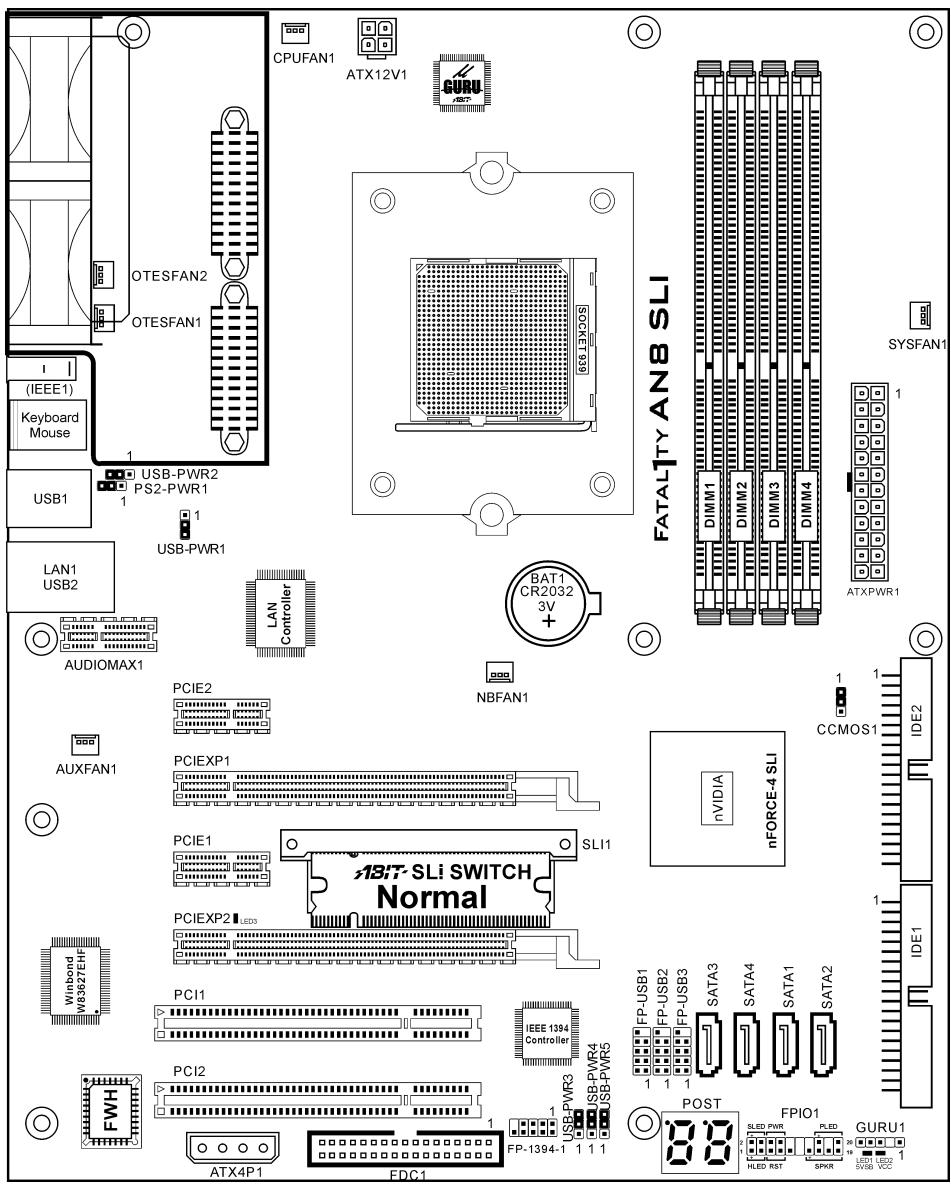
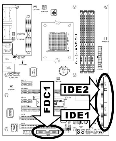
1-3. Layout Diagram
For more information:
WWW.ABIT.COM.TW
WWW.FATALITY.COM
Chapter 2. Hardware Setup
Before the Installation: Turn off the power supply switch (fully turn off the +5V standby power), or disconnect the power cord before installing or unplugging any connectors or add-on cards. Failing to do so may cause the motherboard components or add-on cards to malfunction or be damaged.
2-1. Install The Motherboard
Most computer chassis have a base with many mounting holes to allow a motherboard to be securely attached and at the same time, prevent short circuits. There are two ways to attach the motherboard to the chassis base:
- use with studs
- use with spacers
In principle, the best way to attach the board is with studs. Only if you are unable to do this should you attach the board with spacers. Line up the holes on the board with the mounting holes on the chassis. If the holes line up and there are screw holes, you can attach the board with studs. If the holes line up and there are only slots, you can only attach with spacers. Take the tip of the spacers and insert them into the slots. After doing this to all the slots, you can slide the board into
position aligned with slots. After the board has been positioned, check to make sure everything is OK before putting the chassis back on.

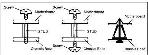
ATTENTION: To prevent shorting the PCB circuit, please REMOVE the metal studs or spacers if they are already fastened on the chassis base and are without mounting-holes on the motherboard to align with.
2-2. Install CPU, Heatsink and Fan Assembly
Please pay attention to the following notices before installing the CPU and heatsink/fan assembly.
- Always use the processor with the Heatsink and Fan Assembly installed.
- Do not touch the pins on the processor.
- If you ever need to reinstall the Heatsink and fan Assembly, please clean the heatsink surface and apply new thermal interface material first.
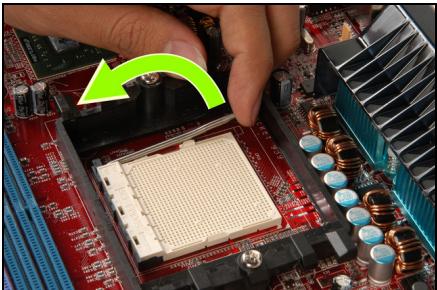
1. Pull out the socket locking lever slightly, then lift it up.
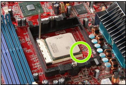
2. Align the corner with triangle mark of the processor with the marking on the motherboard, and then place the processor vertical down into the socket.
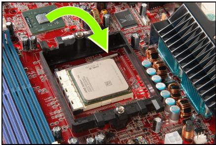
3. Lower the locking lever to the fully locked position.
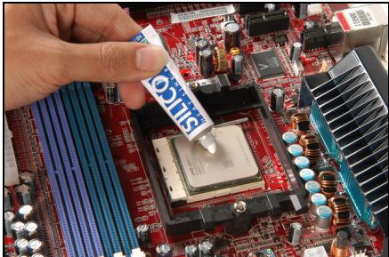
4. Apply thermal interface material.
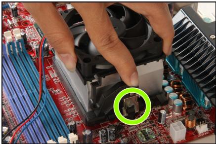
5. Place the heatsink and fan assembly onto the retention frame. Match the heatsink clip with the socket mounting lug. Hook the spring clip to the mounting lug.
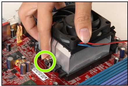
- On the other side, push the retention clip straight down to lock into the plastic lug on the retention frame.
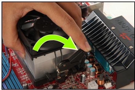
- Turn the cam lever to lock into the retention frame.
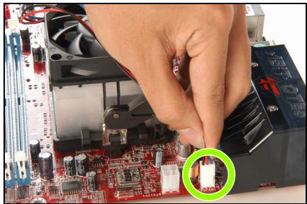
- Attach the four-pin power plug from the heatsink and fan assembly to the CPU FAN connector.
For detailed information on how to install your heatsink and fan assembly, please refer to the instruction manual that came packed with the heatsink and fan assembly you bought.
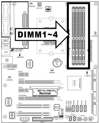
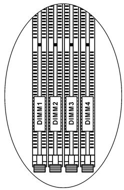
2-3. Install System Memory
This motherboard provides four 184-pin DDR DIMM slots for Single/Dual Channel DDR 400/333/266 memory modules with memory expansion size up to 4GB.
Table 2-1. Valid Memory Configurations
| Bank | Memory Module | Total Memory |
| Bank 0, 1 (DIMM1) | 128, 256, 512MB, 1GB | 128MB ~ 1GB |
| Bank 2, 3 (DIMM2) | 128, 256, 512MB, 1GB | 128MB ~ 1GB |
| Bank 4, 5 (DIMM3) | 128, 256, 512MB, 1GB | 128MB ~ 1GB |
| Bank 6, 7 (DIMM4) | 128, 256, 512MB, 1GB | 128MB ~ 1GB |
| Total System Memory | 128MB ~ 4GB | |
Table 2-2. Unbuffered DIMM Support For AMD 939-pin Processor
| Data Bus | DIMM1 | DIMM2 | DIMM3 | DIMM4 | Maximum DRAM Speed |
| 64-bits (Single Channel) | Single rank | N/A | Empty | N/A | DDR400 |
| Double rank | N/A | Empty | N/A | DDR400 | |
| Empty | N/A | Single rank | N/A | DDR400 | |
| Empty | N/A | Double rank | N/A | DDR400 | |
| Single rank | N/A | Single rank | N/A | DDR400 | |
| Single rank | N/A | Double rank | N/A | DDR400 | |
| Double rank | N/A | Single rank | N/A | DDR400 | |
| Double rank | N/A | Double rank | N/A | DDR333 | |
| 128-bits (Dual Channel) | Single rank | Single rank | Empty | Empty | DDR400 |
| Double rank | Double rank | Empty | Empty | DDR400 | |
| Empty | Empty | Single rank | Single rank | DDR400 | |
| Empty | Empty | Double rank | Double rank | DDR400 | |
| Single rank | Single rank | Single rank | Single rank | DDR400 | |
| Single rank | Single rank | Double rank | Double rank | DDR400 | |
| Double rank | Double rank | Single rank | Single rank | DDR400 | |
| Double rank | Double rank | Double rank | Double rank | DDR333 |
To reach the performance of Dual Channel DDR, the following rules must be obeyed:
- When installing TWO DIMM modules: Install DIMM modules of the same type and size for slots [DIMM1] + [DIMM2] or slots [DIMM3] + [DIMM4].
- When installing FOUR DIMM modules: Install DIMM modules of the same type and size for slots [DIMM1] + [DIMM2], and slots [DIMM3] + [DIMM4].
NOTE: Usually there is no hardware or BIOS setup requires after adding or removing memory modules, but you will have to clear the CMOS memory first if any memory module related problem occurs.
Power off the computer and unplug the AC power cord before installing or removing memory modules.
- Locate the DIMM slot on the board.
- Hold two edges of the DIMM module carefully, keep away of touching its connectors.
- Align the notch key on the module with the rib on the slot.
- Firmly press the module into the slots until the ejector tabs at both sides of the slot automatically snaps into the mounting notch. Do not force the DIMM module in with extra force as the DIMM module only fit in one dire
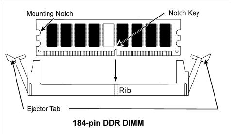
- To remove the DIMM modules, push the two ejector tabs on the slot outward simultaneously, and then pull out the DIMM module.
ATTENTION: Static electricity can damage the electronic components of the computer or optional boards. Before starting these procedures, ensure that you are discharged of static electricity by touching a grounded metal object briefly.
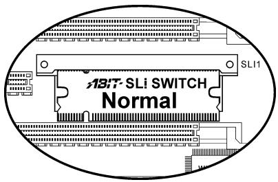
2-4. Install two Graphics Cards with NVIDIA SLI Technology
This motherboard supports the NVIDIA SLI (Scalable-Link-Interface) technology, allowing the operation of two identical (the same model from the same manufacturer) PCI Express x16 graphics cards.
NOTE: The NVIDIA SLI technology currently supports the Windows XP operating system only.
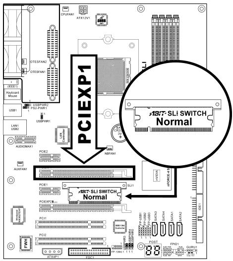
Normal Mode: Leave the SLI Switch to its default Normal mode and insert the graphics card into PCIEXP1 slot. The PCIEXP2 slot functions as a PCIE x1 slot under this mode.
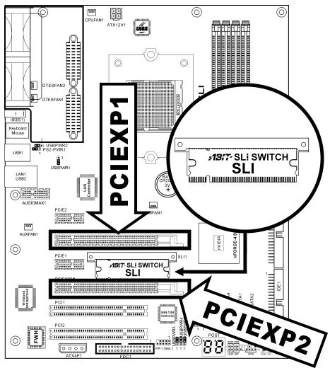
SLI Mode: Switch the SLI Switch to SLI Mode and insert the SLI-ready graphics cards into PCIEXP1 and PCIEXP2 slots.
NOTE: When PCIEXP2 slot functions as a PCIE x1 slot under Normal mode, insert the PCIE x1 card into the marked area of PCIEXP2 slot.
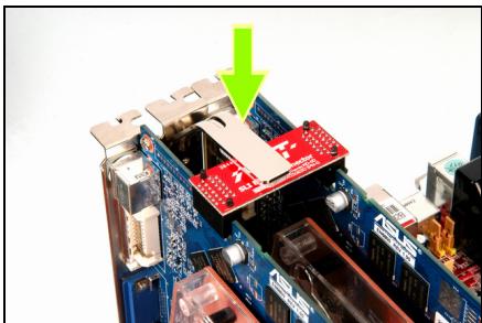
This motherboard is factory pre-installed with an ABIT SLI switchboard. By the default "Normal" mode, this motherboard is set for one single graphics card operation. To operate two graphics cards on this motherboard, you will have to set the switchboard to "SLI" mode in advance.
Prepare two identical NVIDIA certified, SLI-ready PCI Express x16 graphics cards.
- Make sure the graphics card driver supports the NVIDIA SLI technology. Download the latest driver form NVIDIA website (www.nvidia.com).
- Make sure your power supply unit is sufficient to provide the minimum power required.
Please follow the instructions below to set the system to SLI mode and install your graphics cards.
NOTE: Please handle the switchboard with caution. Watch out for the sharp edges.
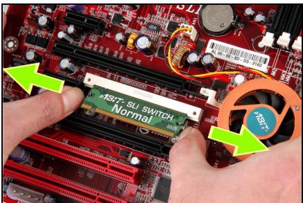
- Simultaneously push the two retention clips at both ends outward to release the switchboard. Carefully pull the switchboard out of the slot.
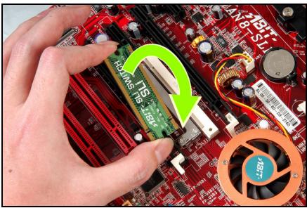
- Flip the switchboard over to the side labeled with "SLI". Carefully insert the switchboard into the slot.
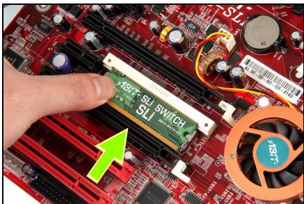
- Slightly push down the switchboard until the retention clip snap into places. Make sure the switchboard is completely inserted into the slot.
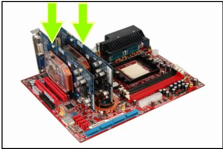
- Insert the two graphics cards into PCIEXP1 and PCIEXP2 slots on the motherboard.
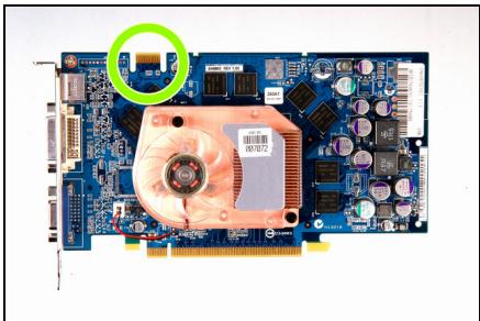
- There are goldfingers on your SLI Graphics Cards reserved for the SLI Bridge Connector.
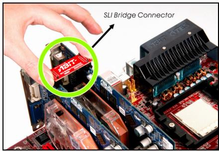
6. Insert the SLI Bridge Connector into the SLI goldfingers on each graphics card.
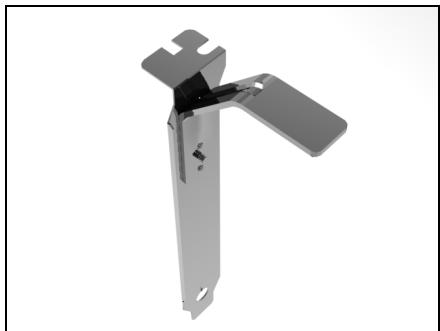
7. The SLI bracket included in the package is used for supporting the SLI bridge connector and the two SLI graphics cards.
8. Insert the SLI bracket into the bracket slot between the graphics cards. Secure the SLI bracket and the graphics cards to the chassis with screws.
NOTE: The OTES SLipstream that packed in the package is optional. Please refer to the Quick Installation Guide of the OTES SLipstream if you wish to install it.
IMPORTANT: Please disable the following items in BIOS setup while running under SLI mode: All the "FanEQ controls" (CPU, NB, SYS, OTES1, OTES2 and AUX FanEQ Control) and "Cool'n'Quiet Technology". The system may be unstable without doing so. Detail information about these items will be described in "Chapter 3. BIOS Setup".
For more information:
WWW.ABIT.COM.TW
WWW.FATALITY.COM
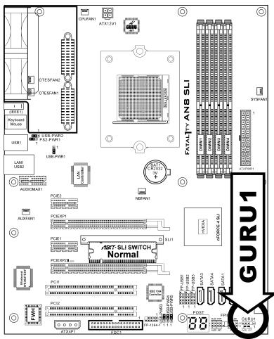
2-5. Connectors, Headers and Switches
Here we will show you all of the connectors, headers and switches, and how to connect them. Please read the entire section for necessary information before attempting to finish all the hardware installation inside the computer chassis. A complete enlarged layout diagram is shown in Chapter 1 for all the positions of connectors and headers on the board that you may refer to.
WARNING: Always power off the computer and unplug the AC power cord before adding or removing any peripheral or component. Failing to do so may cause severe damage to your motherboard and/or peripherals. Plug in the AC power cord only after you have carefully checked everything.
(1).ATX Power Input Connectors
This motherboard provides three power connectors to connect ATX12V power supplier.
NOTE: This 24-pin power connector (ATXPWR1) is compatible with the older 20-pin plug. When plugging a 20-pin plug to this connector, pins 11, 12, 23, and 24 should be left unconnected.
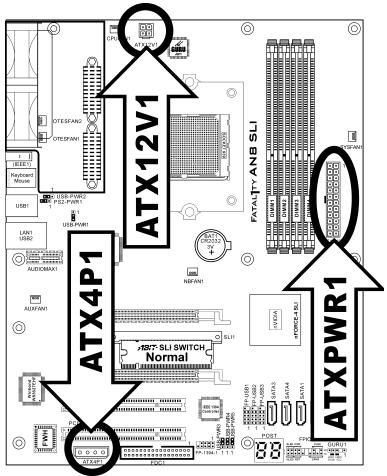

ATX12V1
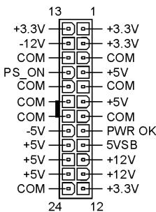
ATXPWR1
NOTE: For a heavily loaded system, a power supply that provides a minimum of 350W and 20A on the +5VDC rail is recommended. To support wake-up features, 2A on the +5VSB rail is required.
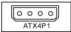
The auxiliary 12V power connector [ATX4P1] provides an additional power source for devices added on PCI Express slots. It is highly recommended to attach 12V power from the power supplier for the best system stability.
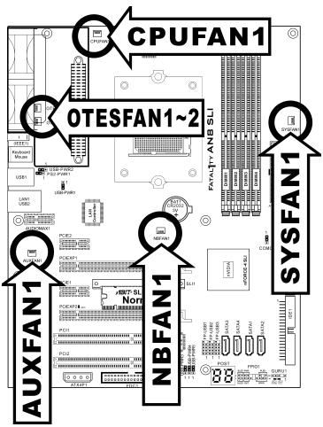
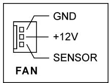
(2). FAN Power Connectors
These connectors each provide power to the cooling fans installed in your system.
- CPUFAN1: CPU Fan Power Connector
- NBFAN1: Chipset Fan Power Connector
- SYSFAN1: System Fan Power Connector
- AUXFAN1: Auxiliary Fan Power Connector
- OTESFAN1, OTESFAN2: OTES Fan Power Connector
WARNING: These fan connectors are not jumpers. DO NOT place jumper caps on these connectors.
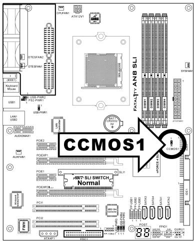
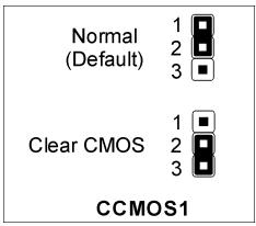
(3). CMOS Memory Clearing Header
This header uses a jumper cap to clear the CMOS memory.
Pin 1-2 shorted (default): Normal operation.
Pin 2-3 shorted: Clear CMOS memory.
WARNING: Turn the power off first (including the +5V standby power) before clearing the CMOS memory. Failing to do so may cause your system to work abnormally or malfunction.
(4). Front Panel Switches & Indicators Headers
This header is used for connecting switches and LED indicators on the chassis front panel.
Watch the power LED pin position and orientation. The mark "+" aligning to the pin in the figure below stands for positive polarity for the LED connection. Please pay attention to connect these headers. A wrong orientation will simply cause the LED to not light, but a wrong connection of the switches could cause system malfunction.
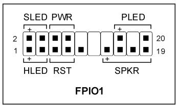
- HLED (Pin 1, 3):
Connects to the HDD LED cable of chassis front panel.
RST (Pin 5, 7):
Connects to the Reset Switch cable of chassis front panel.
SPKR (Pin 13, 15, 17, 19):
Connects to the System Speaker cable of chassis.
- SLED (Pin 2, 4):
Connects to the Suspend LED cable (if there is one) of chassis front panel.
PWR (Pin 6,8):
Connects to the Power Switch cable of chassis front panel.
- PLED (Pin 16, 18, 20):
Connects to the Power LED cable of chassis front panel.
(5). Additional USB Port Headers
These headers each provide 2 additional USB 2.0 ports connection through an USB cable designed for USB 2.0 specifications.
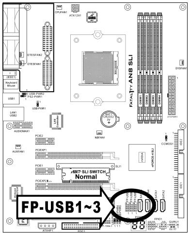
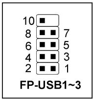
| Pin | Pin Assignment | Pin | Pin Assignment |
| 1 | VCC | 2 | VCC |
| 3 | Data0 - | 4 | Data1 - |
| 5 | Data0 + | 6 | Data1 + |
| 7 | Ground | 8 | Ground |
| 9 | NC | 10 | NC |
(6). Additional IEEE1394 Port Headers
This header provides one additional IEEE1394 port connection through an extension cable and bracket.
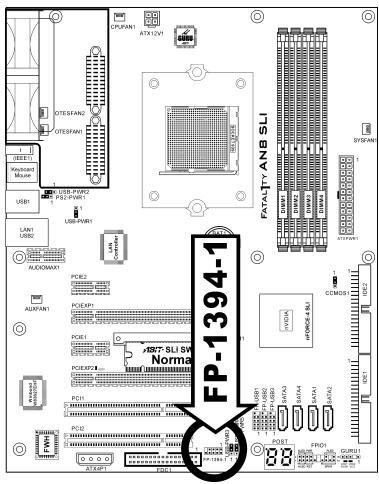
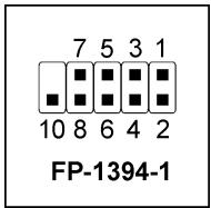
| Pin | Pin Assignment | Pin | Pin Assignment |
| 1 | TPA0 + | 2 | TPA0 - |
| 3 | GND | 4 | GND |
| 5 | TPB0 + | 6 | TPB0 - |
| 7 | +12V | 8 | +12V |
| 9 | NC | 10 | GND |
(7). Wake-up Header
These headers use a jumper cap to enable/disable the wake-up function.
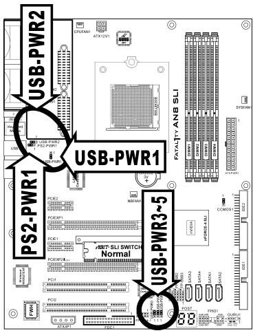
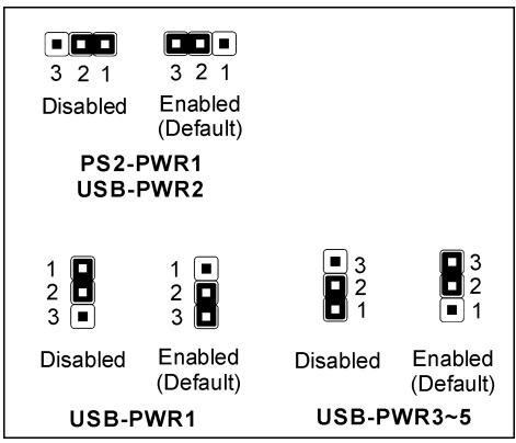
PS2-PWR1:
Pin 1-2 shorted: Disable wake-up function support at Keyboard/Mouse port.
Pin 2-3 shorted (default): Enable wake-up function support at Keyboard/Mouse port.
USB-PWR1:
Pin 1-2 shorted: Disable wake-up function support at USB1 port.
Pin 2-3 shorted (default): Enable wake-up function support at USB1 port.
USB-PWR2:
Pin 1-2 shorted: Disable wake-up function support at USB2 port.
Pin 2-3 shorted (default): Enable wake-up function support at USB2 port.
USB-PWR3:
Pin 1-2 shorted: Disable wake-up function support at FP-USB1 port.
Pin 2-3 shorted (default): Enable wake-up function support at FP-USB1 port.
USB-PWR4:
Pin 1-2 shorted: Disable wake-up function support at FP-USB2 port.
Pin 2-3 shorted (default): Enable wake-up function support at FP-USB2 port.
USB-PWR5:
Pin 1-2 shorted: Disable wake-up function support at FP-USB3 port.
Pin 2-3 shorted (default): Enable wake-up function support at FP-USB3 port.
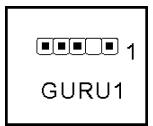
(8). GURU Panel Connection Header
This header is reserved for connecting ABIT's exclusive GURU Panel. For more information, please refer to the included GURU Panel Installation Guide.
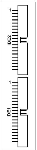
(9). Floppy and IDE Disk Drive Connectors
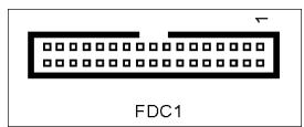
The FDC1 connector connects up to two floppy drives with a 34-wire, 2-connector floppy cable. Connect the single end at the longer length of ribbon cable to the FDC1 on the board, the two connectors on the other end to the floppy disk drives connector. Generally you need only one floppy disk drive in your system.
NOTE: The red line on the ribbon cable must be aligned with pin-1 on both the FDC1 port and the floppy connector.
Each of the IDE port connects up to two IDE drives at Ultra ATA/100 mode by one 40-pin, 80-conductor, and 3-connector Ultra ATA/66 ribbon cables.
Connect the single end (blue connector) at the longer length of ribbon cable to the IDE port of this board, the other two ends (gray and black connector) at the shorter length of the ribbon cable to the connectors of your hard drives.
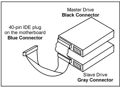
NOTE: Make sure to configure the "Master" and "Slave" relation before connecting two drives by one single ribbon cable. The red line on the ribbon cable must be aligned with pin-1 on both the IDE port and the hard-drive connector.
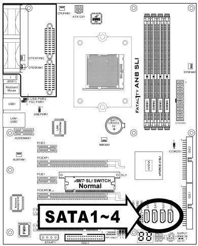
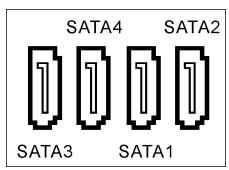
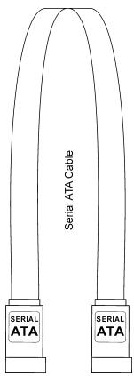
(10). Serial ATA Connectors
These connectors are provided to attach one Serial ATA device at each channel via Serial ATA cable.
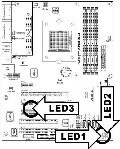
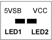
(11). Status Indicators
- LED1 (5VSB): This LED lights up when the power supply is connected with power source.
- LED2 (VCC): This LED lights up when the system power is on.
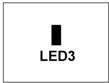
- LED3: This LED lights up when the system works on SLI mode.
(12). POST Code Display
This is an LED device to display the "POST" Code, the acronym of Power On Self Test. The computer will execute the POST action whenever you power on the computer. The POST process is controlled by the BIOS. It is used to detect the status of the computer's main components and peripherals. Each POST Code corresponds to different checkpoints that are also defined by the BIOS in advance. For example, "memory presence test" is an important checkpoint and its POST Code is "C1". When the BIOS execute any POST item, it will write the corresponding POST Code into the address 80h. If the POST passes, the BIOS will process the next POST item and write the next POST Code into the address 80h. If the POST fails, we can check the POST Code in address 80h to find out where the problem lies.
This LED device also displays the "POST" Code of AC2003, an "uGuru" chipset developed exclusively by ABIT computer.
NOTE: The decimal point lights up when executing the AC2003 POST action.
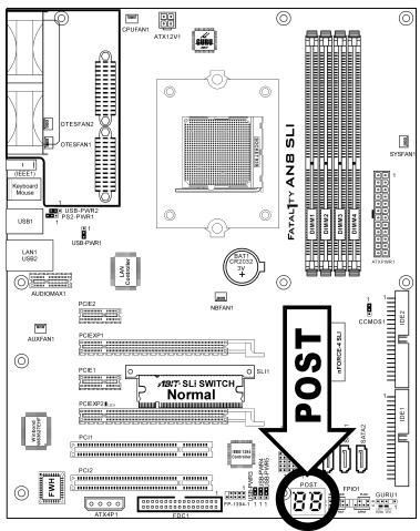

See Appendix for both AWARD and AC2003 POST Code definition.
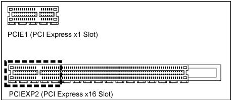
(13). PCI Express x1 Slots
These slots are used to attach the next generation of I/O architecture.
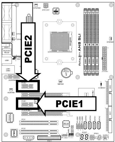
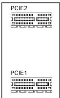
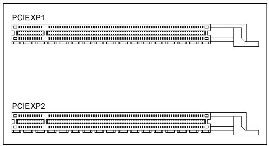
(14). PCI Express x16 Slot
This motherboard supports the operation of one PCI Express x16 graphics card or two SLI-ready PCI Express x16 graphics cards that comply with PCI Express x16 specifications.
By the default "Normal" mode, this motherboard is set for one single graphics card operation. The "PCIEXP1" slot functions as PCI Express x16, while as "PCIEXP2" functions as PCI Express x1.
To operate two graphics cards on this motherboard, you will have to set the SLI switchboard to "SLI" mode in advance. See the description on section "2.4 Install two Graphics Cards with NVIDIA SLI Technology" for details.
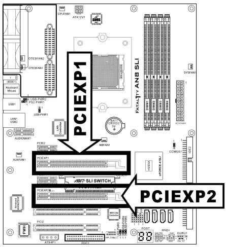
(15). SLI Switchboard Slot
This slot and the pre-installed ABIT SLI Switch set the graphic mode to either Normal or SLI mode.

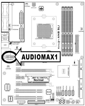
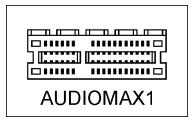
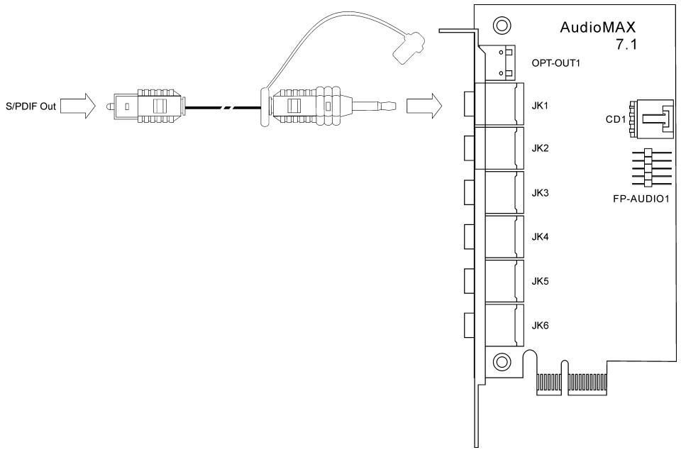
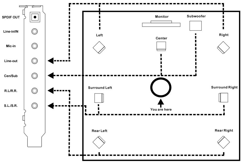
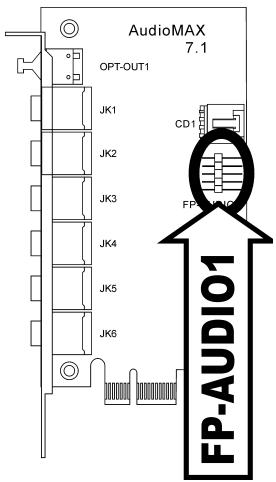
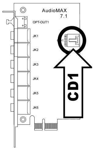
(16). AUDIOMAX Slot
The slot "AUDIOMAX1" provides the audio input/output connection at back panel through an audio daughter-card.
NOTE: Install this daughter-card at slot "AUDIOMAX1".
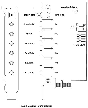
- SPDIF OUT: This connector provides an S/PDIF-Out connection through optical fiber to digital multimedia devices.
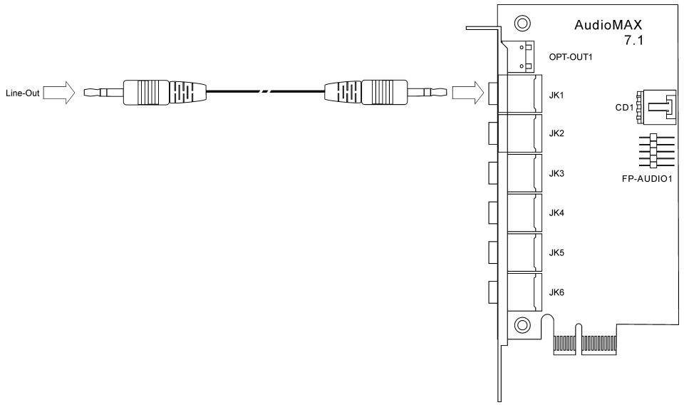
- Line-in/IN: This is a multi-functional connector. This connector provides an S/PDIF-In connection through optical fiber to digital multimedia devices. It also connects to the line out from external audio sources.
- Mic-in: Connects to the plug from external microphone.
- Line-out: Connects to the front left and front right channel in the 7.1-channel or regular 2-channel audio system.
- Cen/Sub: Connects to the center and subwoofer channel in the 7.1 channel audio system.
- R.L./R.R. (Rear Left / Rear Right): Connects to the rear left and rear right channel in the 7.1 channel audio system.
- S.L./S.R. (Surround Left / Surround Right): Connects to the surround left and surround right channel in the 7.1 channel audio system.
S/PDIF Connection:
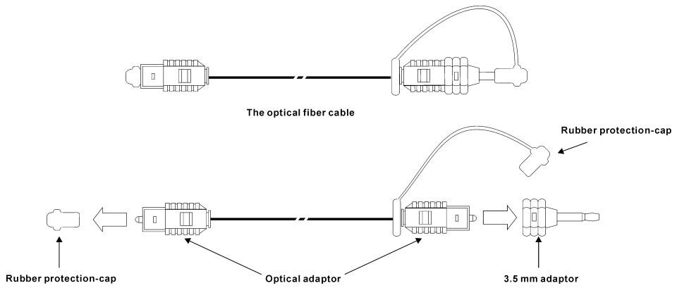
Note: Remove the rubber protection-caps before using this optical fiber cable.
- S/PDIF Output Connection:
- Pull out the 3.5mm adapter at one end. Plug the rest of this end into the [SPDIF OUT] jack on the daughter-card.
- Plug another end into the [S/PDIF In] (Digital In) jack on your digital multimedia device.
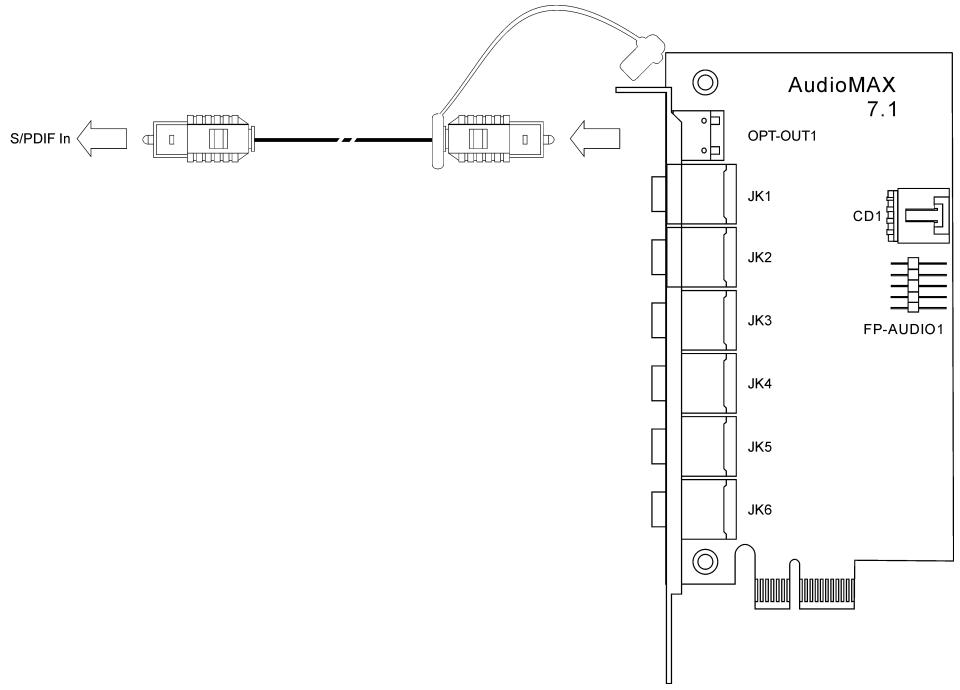
- S/PDIF Input Connection:
- Plug the end with 3.5mm adapter into the [Line-in/IN] jack on this daughter-card. (This jack is used for either optical or line input.)
- Plug another end into the [S/PDIF Out] (Digital Out) jack on your digital multimedia device
Line-in connection:
- Plug one end of a standard 3.5mm audio stereo cable into the [Line-in/IN] jack on this daughter card.
- Plug another end into the [Line-out] jack on your multimedia device
Analog connection for 7.1 channel audio system:
Please follow the below diagram to connect your sound system to the audio daughter card.
(17). Front Panel Audio Connection Header
This header provides the connection to audio connector at front panel.
| FP-AUDIO1 | Pin | Pin Assignment | Pin | Pin Assignment |
| 1 | Audio Mic. | 2 | Ground | |
| 3 | Audio Mic. Bias | 4 | VCC | |
| 5 | Speaker Out Right Channel | 6 | Speaker Out Right Channel Return | |
| 7 | X | 8 | NC | |
| 9 | Speaker Out Left Channel | 10 | Speaker Out Left Channel Return |
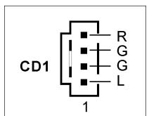
(18). Internal Audio Connectors
These connectors connect to the audio output of internal CD-ROM drive or add-on card.

(19). Back Panel Connectors


Mouse
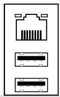
LAN1
OTES
IEEE1
Keyboard
USB1
USB2
- Mouse: Connects to PS/2 mouse.
- Keyboard: Connects to PS/2 keyboard.
- IEEE1: Connects to devices of IEEE1394 protocol
- LAN1: Connects to Local Area Network.
- USB1/USB2: Connects to USB devices such as scanner, digital speakers, monitor, mouse, keyboard, hub, digital camera, joystick etc.
For more information:
WWW.ABIT.COM.TW
WWW.FATALITY.COM
Chapter 3. BIOS Setup
This motherboard provides a programmable EEPROM that you can update the BIOS utility. The BIOS (Basic Input/Output System) is a program that deals with the basic level of communication between processor and peripherals. Use the BIOS Setup program only when installing motherboard, reconfiguring system, or prompted to "Run Setup". This chapter explains the Setup Utility of BIOS utility.
After powering up the system, the BIOS message appears on the screen, the memory count begins, and then the following message appears on the screen:
PRESS DEL TO ENTER SETUP
If this message disappears before you respond, restart the system by pressing <Ctrl> + <Alt> + <Del> keys, or by pressing the Reset button on computer chassis. Only when it failed by these two methods can you restart the system by powering it off and then back on.
After pressing <Del> key, the main menu screen appears.
| Phoenix - Award WorkstationBIOS CMOS Setup Utility | |
| ◆μGuru Utility | ◆PnP/PCI Configurations |
| ◆Standard CMOS Features | Load Fail-Safe Defaults |
| ◆Advanced BIOS Features | Load Optimized Defaults |
| ◆Advanced Chipset Features | Set Password |
| ◆Integrated Peripherals | Save & Exit Setup |
| ◆Power Management Setup | Exit Without Saving |
| Esc : Quit | ↑ ↓ → ← : Select Item |
| F10 : Save & Exit Setup | (NF-CK804-6A61FA1BC-00) |
| F6 : Save PROFILE to BIOS | F7 :Load PROFILE from BIOS |
| OC Guru & ABIT EQ | |
NOTE: In order to increase system stability and performance, our engineering staffs are constantly improving the BIOS menu. The BIOS setup screens and descriptions illustrated in this manual are for your reference only and may not completely match what you see on your screen.
In the BIOS Setup main menu, you can see several options. We will explain these options step by step in the following pages of this chapter, but let us first see a short description of the function keys you may use here.
Esc:
Press this button to quit the BIOS Setup.
↑↓←→:
Press these buttons to choose, in the main menu, the option you want to confirm or to modify.
F10:
When you have completed the setup of BIOS parameters, press this button to save these parameters and to exit the BIOS Setup menu.
3-1. μGuru™ Utility
There are two setup menus in this Guru utility. You may switch between these two by clicking the left or right arrow key on keyboard:
OC Guru:
| μGuru Utility V1.00 | ||
| OC Guru | ABIT EQ | |
| Brand Name: AMD Athlon(tm) 64 Processor 3400+ Frequency: 2200MHz | Item Help | |
| CPU Operating Speed | 2200(200) | |
| - External Clock | 200 MHz | |
| - Multiplier Factor | x11.0 | |
| - PCIE Clock | 100 MHz | |
| Voltages Control | [Auto Detect] | |
| - CPU Core Voltage | 1.350V | |
| - DDR SDRAM Voltage | 2.60V | |
| - DDR VTT Voltage | DDR/2 | |
| - nForce4 Voltage | 1.50V | |
| - HyperTransport Voltage | 1.20V | |
| DDR Ref. Voltage | Default | |
| CPU Ref. Voltage | Default | |
| Power Cycle Statistics | Press Enter | |
| ↑ ↓:Move Enter:Select +/-/PU/PD:Value F8: On The Fly F10:Save ESC:Exit | ||
Brand Name:
This item displays the CPU model name installed on this motherboard.
Frequency:
This item displays the processor speed of the CPU installed on this motherboard.
CPU Operating Speed:
This item displays the CPU operating speed according to the type and speed of your CPU. You can also select the [User Define] option to enter the manual option.
User Define:
WARNING: The wrong settings of the multiplier and external clock in certain circumstances may cause CPU damage. Setting the working frequency higher than the PCI chipset or processor specs, may cause abnormal memory module functioning, system hangs, hard disk drive data loss, abnormal functioning of the VGA card, or abnormal functioning with other add-on cards. Using non-specification settings for your CPU is not the intention of this explanation. These should be used for engineering testing, not for normal applications.
There will be no guaranty for the settings beyond specification, any damage of any component on this motherboard or peripherals result therein is not our responsibility.
External Clock:
This item selects the external clock frequency. Due to the specification limit of the CPU you installed, the speed you set over its standard bus speed is supported, but not guaranteed.
\* Multiplier Factor:
This item displays the multiplier factor for the CPU you installed.
NOTE: Some processors might have this multiplier factor locked, so there is no way to choose a higher multiplier factor.
PCIE Clock
This item selects the PCI Express frequency.
Voltages Control:
This option allows you to switch between the default and user-defined voltages. Leave this setting to default unless the current voltage setting cannot be detected or is not correct. The option "User Define" enables you to select the following voltages manually.
\* CPU Core Voltage:
This item selects the CPU core voltage.
\* DDR SDRAM Voltage:
This item selects the voltage for DRAM slot.
\* DDR VTT Voltage:
This item selects the voltage for VTTMEM port.
\* nForce4 Voltage:
This item selects the NB voltage.
\* HyperTransport Voltage:
This item selects the voltage for LDT Bus.
DDR Ref Voltage:
This Item selects the voltage for DDR memory reference.
CPU Ref Voltage:
This Item selects the voltage for CPU memory reference.
Power Cycle Statistics:
Click
| μGuru Utility V1.00 | ||
| OC Guru | ABIT EQ | |
| Power Cycle Statistics | Item Help | |
| PC Up Time | 1 Hours | |
| PC Up Time Total | 8 Hours | |
| PC Power Cycles | 44 Cycles | |
| PC Reset Button Cycles | 0 Cycles | |
| AC Power On Total Time | 16 Hours | |
| AC Power Cycles | 24 Cycles | |
| ↑ ↓:Move Enter:Select +/-/PU/PD:Value F8: On The Fly F10:Save ESC:Exit | ||
These items display the power cycle statistics for each element.
ABIT EQ:
Click right-arrow key to switch from OC Guru setup menu to ABIT EQ setup menu:
| μGuru Utility V1.00 | ||
| OC Guru | ABIT EQ | |
| ABIT EQ Beep Control | Enabled | |
| Temperature Monitoring | Press Enter | |
| Voltage Monitoring | Press Enter | |
| Fan Speed Monitoring | Press Enter | |
| FanEQ1 Control | Press Enter | |
| FanEQ2 Control | Press Enter | |
| ↑ ↓:Move Enter:Select +/-/PU/PD:Value | F10:Save ESC:Exit | |
ABIT EQ Beep Control:
This item allows you to enable or disable ABIT EQ Beep Control function.

Temperature Monitoring:
Click
| μGuru Utility V1.00 | |||||
| OC Guru | ABIT EQ | ||||
| Temperature Monitoring | |||||
| Reading | Shutdown Enable | Shutdown Temp. | Beep Enable | Beep Temp. | |
| (*)CPU Temperature | 51°C/123°F | (*) | 85°/185°F | (*) | 75°C/167°F |
| (*)SYS Temperature | 33°C/99°F | () | 65°C/149°F | (*) | 55°C/131°F |
| (*)PWM Temperature | 43°C/109°F | () | 90°C/194°F | (*) | 88°C/176°F |
| ↑↓:Move Enter:Select +/-/PU/PD:Value F10:Save ESC:Exit | |||||
CPU Temperature/System Temperature/PWM Temperature:
These items display the temperatures of CPU, System, and Power Module.
\* Shutdown Enable:
Use <Space> key to enable system shutdown function. If the CPU/System/PWM's temperature exceeds the shutdown temperature limit, the system would shutdown automatically.
\* Shutdown Temp.:
This item sets the temperature that would shutdown the system automatically in order to prevent system overheats.
\* Beep Enable:
Use
\* Beep Temp.:
This item selects the warning temperature limit.
NOTE: The shutdown temperature must be set above the warning temperature.

Voltage Monitoring:
Click
| μGuru Utility V1.00 | |||||
| OC Guru | ABIT EQ | ||||
| Voltage Monitoring | High Limit | Low Limit | |||
| Reading | Shutdown Enable | Beep Enable | |||
| (*)CPU Core Voltage | 1.550V | (*) | (*) | 1.89V | 1.00V |
| (*)DDR Voltage | 2.70V | () | (*) | 2.90V | 2.10V |
| (*)DDR VTT Voltage | 1.35V | () | (*) | 1.55V | 1.05V |
| (*)nForce4 Voltage | 1.52V | () | (*) | 1.80V | 1.20V |
| (*)nForce4 Standby Voltage | 1.50V | () | (*) | 1.85V | 1.25V |
| (*)HyperTransport Voltage | 1.19V | () | (*) | 1.45V | 0.95V |
| (*)CPU VDDA 2.5V Voltage | 2.58V | () | (*) | 3.00V | 2.00V |
| (*)ATX +12V | 11.70V | () | (*) | 14.40V | 9.60V |
| (*)ATX +5V | 5.03V | () | (*) | 6.00V | 4.00V |
| (*)ATX +3.3V | 3.39V | () | (*) | 3.95V | 2.65V |
| (*)ATX 5VSB | 5.06V | () | (*) | 6.00V | 4.00V |
| ↑↓:Move Enter:Select +/-/PU/PD:Value F10:Save ESC:Exit | |||||
All Voltages:
These items display the voltage of each element.
\* Shutdown Enable:
Use
\* Beep Enable:
Use
* High/Low Limit:
These items set the high and low voltage limit.
NOTE: The value of high limit must be set above the one of low limit.

Fan Speed Monitoring:
Click
| μGuru Utility V1.00 | |||||
| OC Guru | ABIT EQ | ||||
| Fan Speed Monitoring | |||||
| Reading | Shutdown Enable | Beep Enable | Low | Limit | |
| (*)CPU FAN Speed | 4020 RPM | (*) | (*) | 1200 | RPM |
| (*)NB FAN Speed | N/A | () | () | 1200 | RPM |
| ()SYS FAN Speed | N/A | () | () | 1200 | RPM |
| (*)OTES1 FAN Speed | N/A | () | () | 1200 | RPM |
| (*)OTES2 FAN Speed | N/A | () | () | 1200 | RPM |
| (*)AUX FAN Speed | N/A | () | () | 1200 | RPM |
| ↑↓:Move Enter:Select +/-/PU/PD:Value | F10:Save ESC:Exit | ||||
CPU/NB/SYS/OTES1/OTES2/AUX FAN Speed:
These items display the speed of the fans connected to CPU, NB, SYS, OTES1, OTES2 and AUX FAN headers.
\* Shutdown Enable:
Use
\* Beep Enable:
Use
\* Low Limit:
This item sets the low limit of fan speed.
NOTE: Only the fans with 3-pin plugs provide the speed monitoring function.

FanEQ1 Control:
| μGuru Utility V1.00 | ||
| OC Guru | ABIT EQ | |
| FanEQ1 Control | ||
| CPU FanEQ Control | Enabled | Item Help |
| -Reference Temperature | CPU Temperature | |
| -Control Temperature High | 65°C/149°F | |
| -Control Temperature Low | 35°C/95°F | |
| -DC Fan Voltage High | 12.0V | |
| -DC Fan Voltage Low | 8.0V | |
| NF4 FanEQ Control | Enable | |
| -Reference Temperature | SYS Temperature | |
| -Control Temperature High | 45°C/113°F | |
| -Control Temperature Low | 35°C/95°F | |
| -DC Fan Voltage High | 12.0V | |
| -DC Fan Voltage Low | 8.0V | |
| SYS FanEQ Control | Disabled | |
| -Reference Temperature | SYS Temperature | |
| -Control Temperature High | 45°C/113°F | |
| -Control Temperature Low | 35°C/95°F | |
| -DC Fan Voltage High | 12.0V | |
| -DC Fan Voltage Low | 8.0V | |
| ↑ ↓:Move Enter:Select +/-/PU/PD:Value | F10:Save ESC:Exit | |

FanEQ2 Control:
| μGuru Utility V1.00 | ||
| OC Guru | ABIT EQ | |
| FanEQ1 Control | ||
| OTES1 FanEQ Control | Enabled | Item Help |
| -Reference Temperature | SYS Temperature | |
| -Control Temperature High | 45°C/113°F | |
| -Control Temperature Low | 35°C/95°F | |
| -DC Fan Voltage High | 12.0V | |
| -DC Fan Voltage Low | 6.0V | |
| OTES2 FanEQ Control | Enabled | |
| -Reference Temperature | SYS Temperature | |
| -Control Temperature High | 45°C/113°F | |
| -Control Temperature Low | 35°C/95°F | |
| -DC Fan Voltage High | 12.0V | |
| -DC Fan Voltage Low | 6.0V | |
| AUX FanEQ Control | Disabled | |
| -Reference Temperature | SYS Temperature | |
| -Control Temperature High | 45°C/113°F | |
| -Control Temperature Low | 35°C/95°F | |
| -DC Fan Voltage High | 12.0V | |
| -DC Fan Voltage Low | 8.0V | |
| ↑↓:Move Enter:Select +/-/PU/PD:Value F10:Save ESC:Exit | ||
CPU/NB/SYS/OTES1/OTES2/AUX FanEQ Control:
When set to [Enabled], these items control the CPU, NB, SYS, OTES1, OTES2 and/or AUX fan speed by the following setting combinations.
NOTE: Please disable all the FanEQ control items (CPU, NB, SYS, OTES1, OTES2 and AUX FanEQ Control) while running under SLI mode.
\* Reference Temperature:
This item selects the reference point for taking temperature among the available options of CPU, SYS, and PWM Temperature, but there is only one "CPU Temperature" item to choose for the "CPU FanEQ Control".
* Control Temperature High/Low:
This item sets the high and low temperature limits desired for the fan speed control.
DC Fan Voltage High/Low:
This item sets the high and low voltage limits for the fan.
NOTE: The value of high limit must be set above the one of low limit.
3-2. Standard CMOS Features
This section contains the basic configuration parameters of the BIOS. These parameters include date, hour, VGA card, FDD and HDD settings.
| Phoenix - Award WorkstationBIOS CMOS Setup Utility Standard CMOS Features | ||
| Date (mm:dd:yy) | Thu. Jan 1 2005 | |
| Time (hh:mm:ss) | 12 : 34 : 56 | |
| IDE Channel 1 Master | None | |
| IDE Channel 1 Slave | None | |
| IDE Channel 2 Master | None | |
| IDE Channel 2 Slave | None | |
| IDE Channel 3 Master | None | |
| IDE Channel 4 Master | None | |
| IDE Channel 5 Master | None | |
| IDE Channel 6 Master | None | |
| Drive A | 1.44M, 3.5 in. | |
| Drive B | None | |
| Halt On | All, But keyboard | |
| Base Memory | 640K | |
| Extended Memory | 1046520K | |
| Total Memory | 1047552K | |
| ↑ ↓:Move Enter:Select +/-/PU/PD:Value F10:Save ESC:Exit F1:General Help F5:Previous Values F6:Fail-Safe Defaults F7:Optimized Defaults | ||
Date (mm:dd:yy):
This item sets the date you specify (usually the current date) in the format of [Month], [Date], and [Year].
Time (hh:mm:ss):
This item sets the time you specify (usually the current time) in the format of [Hour], [Minute], and [Second].

IDE Channel 1 Master/Slave, IDE Channel 2 Master/Slave, IDE Channel 3 Master, IDE Channel 4 Master, IDE Channel 5 Master, IDE Channel 6 Master:
Click
| Phoenix - Award WorkstationBIOS CMOS Setup Utility IDE Channel 1 Master | ||
| IDE HDD Auto-Detection | Press Enter | Item Help |
| IDE Channel 1 Master | Auto | |
| Access Mode | Auto | |
| Capacity | 0 MB | |
| Cylinder | 0 | |
| Head | 0 | |
| Precomp | 0 | |
| Landing Zone | 0 | |
| Sector | 0 | |
| ↑ ↓:Move Enter:Select +/-/PU/PD:Value F10:Save ESC:Exit F1:General Help F5:Previous Values F6:Fail-Safe Defaults F7:Optimized Defaults | ||
IDE HDD Auto-Detection:
This item allows you to detect the parameters of IDE drives by pressing
IDE Channel 1 Master/Slave, IDE Channel 2 Master/Slave, IDE Channel 3 Master, IDE Channel 4 Master, IDE Channel 5 Master, IDE Channel 6 Master:
When set to [Auto], the BIOS will automatically check what kind of IDE drive you are using. If you want to define your own drive by yourself, set it to [Manual] and make sure you fully understand the meaning of the parameters. Please refer to the instruction manual provided by the device's manufacturer to get the setting right.
Access Mode:
This item selects the mode to access your IDE devices. Leave this item to its default [Auto] setting to detect the access mode of your HDD automatically.
Capacity:
This item displays the approximate capacity of the disk drive. Usually the size is slightly greater than the size of a formatted disk given by a disk-checking program.
Cylinder:
This item configures the number of cylinders.
Head:
This item configures the number of read/write heads.
| Precomp:This item displays the number of cylinders at which to change the write timing. |
| Landing Zone:This item displays the number of cylinders specified as the landing zone for the read/write heads. |
| Sector:This item configures the number of sectors per track.Back to Standard CMOS Features Setup Menu: |
| Drive A & Drive B:This item sets the type of floppy drives (usually only Drive A) installed. |
| Halt On:This item determines whether the system stops if an error is detected during system boot-up.[All Errors]: The system-boot will stop whenever the BIOS detect a non-fatal error.[No Errors]: The system-boot will not stop for any error detected.[All, But Keyboard]: The system-boot will stop for all errors except a keyboard error.[All, But Diskette]: The system-boot will stop for all errors except a diskette error.[All, But Disk/Key]: The system-boot will stop for all errors except a diskette or keyboard error. |
| Base Memory:This item displays the amount of base memory installed in the system. The value of the base memory is typically 640K for system with 640K or more memory size installed on the motherboard. |
| Extended Memory:This item displays the amount of extended memory detected during system boot-up. |
| Total Memory:This item displays the total memory available in the system. |
3-3. Advanced BIOS Features
| Phoenix - Award WorkstationBIOS CMOS Setup Utility Advanced BIOS Features | ||
| ►Removable Device Priority | Press Enter | Item Help |
| ►Hard Disk Boot Priority | Press Enter | |
| ►CD-ROM Boot Priority | Press Enter | |
| First Boot Device | Removable | |
| Second Boot Device | CD-ROM | |
| Third Boot Device | Hard Disk | |
| Boot Other Device | Enabled | |
| Swap Floppy Drive | Disabled | |
| Boot Up Floppy Seek | Disabled | |
| Boot Up NumLock Status | On | |
| Security Option | Setup | |
| MPS Version Ctrl For OS | 1.4 | |
| Delay For HDD (Secs) | 0 | |
| Full Screen Logo Show | Disabled | |
| Disable Unused PCI Clock | Enable | |
| ↑↓:Move Enter:Select +/-/PU/PD:Value F10:Save ESC:Exit F1:General Help F5:Previous Values F6:Fail-Safe Defaults F7:Optimized Defaults | ||
Removable Device Priority:
This item allows you to select the booting priority of removable devices.
Hard Disk Boot Priority:
This item selects the hard disks booting priority. By pressing
This item functions only when there is the option of [Hard Disk] in any one of the First/Second/Third Boot Device items.
CD-ROM Boot Priority:
This item allows you to select the booting priority of CD-ROM devices.
NOTE: This item appears only if you install CD-ROM devices to your computer.
First Boot Device / Second Boot Device / Third Boot Device / Boot Other Device:
Select the drive to boot first, second and third in the [First Boot Device], [Second Boot Device], and [Third Boot Device] items respectively. The BIOS will boot the operating system according to the sequence of the drive selected. Set [Boot Other Device] to [Enabled] if you wish to boot from another device other than these three items.
Swap Floppy Drive:
When set to [Enabled], and the system is booting from the floppy drive, the system will boot from drive B instead of the regular drive A. There must be two floppy drives connected in the system to use this function.
Boot Up Floppy Seek:
When the computer boots up, the BIOS detects if the system has a FDD or not. When this item is set to Enabled, if the BIOS detects no floppy drive, it will display a floppy disk drive error message. If this item is disabled, the BIOS will skip this test. The default setting is Disabled.
Boot Up NumLock Status:
This item determines the default state of the numeric keypad at system booting up.
[On]: The numeric keypad functions as number keys.
[Off]: The numeric keypad functions as arrow keys.
Security Option:
This item determines when the system will prompt for password - every time the system boots or only when it enters the BIOS setup.
[Setup]: The password is required only when accessing the BIOS Setup.
[System]: The password is required each time the computer boots up.
To disable security, select Set Password at main menu and then you will be asked to enter the password. Do not type anything and just press the
NOTE: Don't forget your password. If you forget the password, you will have to open the computer case and clear all information in the CMOS before you can start up the system. But by doing this, you will have to reset all previously set options.
MPS Version Ctrl For OS:
This item specifies which version of MPS (Multi-Processor Specification) this motherboard will use. Leave this item to its default setting.
Delay For HDD (Secs):
This item allows the BIOS to support some old or special IDE devices by prolonging this delay time. A larger value will give more delay time to the device for which to initialize and to prepare for activation.
Full Screen LOGO Show:
This item determines to show the full screen logo when booting.
Disable unused PCI Clock:
This option disables the clock of PCI slot that is not in use.
[Enabled]: The system automatically detects the unused PCI slots, and stop sending clock signal to these unused PCI slots.
[Disabled]: The system always sends clock signal to all PCI slots.
NOTE: Set this option to [Disabled] setting if there are adapters that cannot be automatically detected by the system and will cause malfunction.
3-4. Advanced Chipset Features
| Phoenix - Award WorkstationBIOS CMOS Setup Utility Advanced Chipset Features | |
| HT Frequency 4X HT Width ↓16 ↑16 DRAM Configuration Press Enter SSE/SSE2 Instructions Enable System BIOS Cachable Disable | Item Help |
| ↑↓:Move Enter:Select +/-/PU/PD:Value F10:Save ESC:Exit F1:General Help F5:Previous Values F6:Fail-Safe Defaults F7:Optimized Defaults | |
HT Frequency:
This item selects the LDT Bus Frequency.
HT Width:
This item selects the LDT Bus Width.

DRAM Configuration:
Click
| Phoenix - Award WorkstationBIOS CMOS Setup Utility DRAM Configuration | ||
| DRAM Timing Selectable | Auto | Item Help |
| X - DRAM Clock | Auto | |
| X - CAS latency Time | Auto | |
| X - Row Cycle Time | Auto | |
| X - Row Refresh Cycle Time | Auto | |
| X - RAS# to CAS# delay | Auto | |
| X - RAS# to RAS# delay | Auto | |
| X - Min RAS# Active time | Auto | |
| X - RAS# Precharge Time | Auto | |
| X - Write Recovery Time | Auto | |
| X - Write to Read Delay | Auto | |
| X - DRAM Command rate | Auto | |
| X - Burst Length | 4 beats | |
| X - Bank Interleaving | Enabled | |
| 32 bit Dram Memory Hole | Auto | |
| MTRR mapping mode | Continuous | |
| ↑ ↓:Move Enter:Select +/-/PU/PD:Value F10:Save ESC:Exit F1:General Help F5:Previous Values F6:Fail-Safe Defaults F7:Optimized Defaults | ||
DRAM Timing Selectable:
This item selects the DRAM timing mode. When set to "By SPD", the BIOS will read the DRAM module SPD data and automatically set to the values stored in it. Leave this item to its default "Auto" setting.
\* DRAMClock:
This item sets the DRAM clock of your DRAM module. The system may be unstable or unable to boot up if your DRAM module does not support the clock you set.
When set to [By SPD], the BIOS will read the DRAM module SPD data and automatically set the DRAM clock by the value stored in it.
CAS Latency Time:
Three options are available: 2 2.5 3 . The default setting is 2.5. You can select SDRAM CAS (Column Address Strobe) latency time according to your SDRAM specification.
\* Row Cycle Time:
This item specifies the RAS# active to RAS# active time or auto refresh time of the same bank.
\* Row Refresh Cycle Time:
This item specifies the auto refresh active to RAS# active time or RAS# auto refresh time.
\* RAS# to CAS# Delay:
This item specifies the RAS# active to CAS# read write delay time to the same bank.
RAS# to RAS# Delay:
This item specifies the RAS# active to RAS# active delay time of different bank.
\* Min. RAS# Active Time:
This item specifies the minimum RAS# active time.
RAS# Precharge Time:
This item specifies the RAS# precharge time.
\* Write Recovery Time:
This item specifies the time measured from the last write datum is safely registered by the DRAM.
\* Write to Read Delay:
This item specifies the time measured from the rising edge following the last non-masked data strobe to the rising edge of the next read command.
DRAM Command Rate:
Two options are available: 2T Command or 1T Command. The default setting is 2T Command. When the host (northbridge) locates the desired memory address, it then processes the wait state of commands.
\* Burst Length
DDR SDRAM modules provide a Burst mode that means an auto precharge function for programmable READ or WRITE burst lengths of 4 or 8 locations.
This means that if we set burst length to 8, the address bus will access 8 bytes each cycle to precharge, etc.
Bank Interleaving:
Three options are available: Disabled 2 Way 4 Way. The default setting is Disabled. Depending on your SDRAM module structure, the 4-Way setting can offer the best performance. If you choose the wrong setting, the computer system will not run in a stable manner. For detailed information on your SDRAM module, please ask your SDRAM module manufacturer.
32 bit Dram Memory Hole:
This item selects the method to remap the 32 bit Dram memory hole. Leave this item to its default "Auto" Setting.
MTRR mapping mode
The item selects the MTRR mapping mode. The MTRR (Memory-Type and Range Registers) controls the access and cacheability of memory regions in the processor.

Back to Advanced Chipset Features Setup Menu:
SSE/SSE2 Instructions:
This item allows you to Enable or Disable the SSE/SSE2 (Streaming SIMD Extensions) instruction set. The default setting is Enabled.
System BIOS Cacheable:
Two options are available: Disabled or Enabled. When you select Enabled, you get faster system BIOS executing speed via the L2 cache.
3-5. Integrated Peripherals
| Phoenix - Award WorkstationBIOS CMOS Setup Utility Integrated Peripherals | ||
| ► Onchip PCI Device | Press Enter | Item Help |
| ► IDE/RAID Function | Press Enter | |
| USB Park Mode | Disabled | |
| USB TD Reads | ISO Queue | |
| USB Periodic Data Reads | ISO Queue | |
| USB Asyn Data Reads | Non-ISO Queue | |
| Onboard FDC Controller | Enabled | |
| Init Display First | PCI Slot | |
| Onboard IEEE1394 Controller | Enabled | |
| ↑ ↓:Move Enter:Select +/-/PU/PD:Value F10:Save ESC:Exit F1:General Help F5:Previous Values F6:Fail-Safe Defaults F7:Optimized Defaults | ||
Onchip PCI Device
Click
| Phoenix - Award WorkstationBIOS CMOS Setup Utility Onchip PCI Device | |
| USB Controller V1.1+V2.0 | Item Help |
| - USB Memory Type Shadow | |
| - USB Keyboard Support Disable | |
| - USB Mouse Support Disable | |
| LAN Controller Auto | |
| - LAN Boot ROM Disabled | |
| ↑ ↓:Move Enter:Select +/-/PU/PD:Value F10:Save ESC:Exit F1:General Help F5:Previous Values F6:Fail-Safe Defaults F7:Optimized Defaults | |
USB Controller:
Three options are available: Disabled V1.1+V2.0 V1.1. The default setting is V1.1 + V2.0 . If you choose to disable this item, the "USB Memory Type" "USB Keyboard Support" and "USB Mouse Support" items will not be able to select in Integrated Peripherals menu.
* USB Memory Type:
This item selects the USB memory type. Choose "Base Memory(640K)" setting if the default "Shadow" setting caused stability issues to your system.
USB Keyboard Support:
This item allows you to select [Enabled] for using USB keyboard in DOS environment, or [Disabled] in OS environment.
USB Mouse Support:
This item allows you to select [Enabled] for using USB mouse in DOS environment, or [Disabled] in OS environment.
LAN Controller:
This option enables or disables the LAN controller.
LAN Boot ROM:
This item allows you to use the boot ROM (instead of a disk drive) to boot-up the system and access the local area network directly.
IDE/RAID Function
Click
| Phoenix - Award WorkstationBIOS CMOS Setup UtilityIDE/RAID Fuction Setup | |
| IDE Function SetupPress EnterRAID ConfigPress Enter | Item Help |
| ↑↓:Move Enter:Select +/-/PU/PD:Value F10:Save ESC:Exit F1:General HelpF5: Previous Values F6: Fail-Safe Defaults F7: Optimized Defaults | |

IDE Function Setup:
Click
| Phoenix - Award WorkstationBIOS CMOS Setup UtilityIDE Fuction Setup | |
| Onboard IDE-1 Controller Enabled | Item Help |
| Onboard IDE-2 Controller Enabled | |
| IDE DMA transfer access Enabled | |
| Serial-ATA 1 Enabled | |
| - SATA DMA transfer Enabled | |
| Serial-ATA 2 Enabled | |
| - SATA 2 DMA transfer Enabled | |
| IDE Prefetch Mode Enabled | |
| ↑ ↓:Move Enter:Select +/-/PU/PD:Value F10:Save ESC:Exit F1:General HelpF5: Previous Values F6: Fail-Safe Defaults F7: Optimized Defaults | |
Onboard IDE-1 Controller / Onboard IDE-2 Controller:
This item allows you to enable or disable the primary (IDE1) and secondary (IDE2) IDE controller. Select [Disabled] if you want to add a different hard drive controller.
IDE DMA transfer access:
This item selects the DMA mode for devices connected through IDE channels.
Serial-ATA 1/Serial ATA 2:
This item enables or disables the on-chip SATA controller.
SATA DMA transfer/SATA 2 DMA transfer:
This item selects the DMA mode for devices connected through SATA channels.
IDE Prefetch Mode:
Two options are available: Disabled or Enabled. The default setting is Enabled. The onboard IDE drive interfaces support IDE prefetching for faster drive accesses. If you install a primary and/or secondary add-in IDE interface, set this field to Disabled if the interface does not support prefetching.

RAID Config:
Click
| Phoenix - Award WorkstationBIOS CMOS Setup Utility RAID Config | |
| - RAID Enable Enabled | Item Help |
| X - IDE Primary Master RAID Disabled | |
| X - IDE Primary Slave RAID Disabled | |
| X - IDE Secondary Master RAID Disabled | |
| X - IDE Secondary Slave RAID Disabled | |
| X - SATA 1 Primary Master RAID Disabled | |
| X - SATA 1 Secondary Master RAID Disabled | |
| X - SATA 2 Primary Master RAID Disabled | |
| X - SATA 2 Secondary Master RAID Disabled | |
| ↑ ↓:Move Enter:Select +/-/PU/PD:Value F10:Save ESC:Exit F1:General Help F5:Previous Values F6:Fail-Safe Defaults F7:Optimized Defaults | |
RAID Enable:
This item allows you to enable or disable the IDE RAID function.
- IDE Primary/Secondary Master/Slave RAID, SATA 1/2 Primary/Secondary Master RAID:
Select the disks that you want to use as RAID disks.

Back to Integrated Peripherals Setup Menu:
USB Park Mode:
This item enables or disables the USB Park Mode. Leave this item to its default setting.
USB TD Reads:
This item selects the mode for the USB TD Reads. Leave this item to its default setting.
USB Periodic Data Reads:
This item selects the mode for the USB Periodic Data Reads. Leave this item to its default setting.
USB Asyn Data Reads:
This item selects the mode for the USB Asyn Data Reads. Leave this item to its default setting.
Onboard FDC Controller:
Two options are available: Enabled and Disabled. The default setting is Enabled. You can enable or disable the onboard FDC controller.
Init Display First:
This item selects which display slot to be initialized first when the system boots.
[PCI Slot]: When the system boots, it will first initialize PCI.
[PCIEx]: When the system boots, it will first initialize PCIE.
Onboard IEEE1394 Controller:
This option enables or disables the IEEE 1394 controller.
3-6. Power Management Setup
| Phoenix - Award WorkstationBIOS CMOS Setup Utility Power Management Setup | ||
| ACPI Suspend Type | S3(Suspend-to-RAM) | Item Help |
| - USB Resume from S3 | Enabled | |
| Power Button Function | Instant-Off | |
| Wake-Up by PME# of PCI | Enabled | |
| Wake-Up by OnChip LAN | Enabled | |
| Wake-Up by Alarm | Disabled | |
| X - Date(of Month) Alarm | 0 | |
| X - Time (hh:mm:ss) Alarm | 0 : 0 : 0 | |
| Cool'n'Quiet Technology | Disabled | |
| POWER ON Function | BUTTON ONLY | |
| X - KB Power ON Password | Enter | |
| X - Hot Key Power ON | Ctrl-F1 | |
| Restore on AC Power Loss | Power Off | |
| ↑ ↓:Move Enter:Select +/-/PU/PD:Value F10:Save ESC:Exit F1:General Help F5:Previous Values F6:Fail-Safe Defaults F7:Optimized Defaults | ||
ACPI Suspend Type:
This item selects the type of Suspend mode.
[S1(PowerOn-Suspend)]: Enables the Power On Suspend function.
[S3(Suspend-To-RAM)]: Enables the Suspend to RAM function.
USBResumefromS3:
Two options are available: Disabled or Enabled. The default setting is Disabled. When set to Enabled, any event related to onchip USB will power on the system. This item can be configured only if the item "ACPI Suspend Type" is set to [S3(STR)].
Power Button Function:
Two options are available: Delay 4 Sec or Instant-Off. The default setting is Instant-Off. It is activated when the user presses the power button for more than four seconds while the system is in the working state, then the system will transition to the soft-off (Power off by software). This is called the power button over-ride.
Wakeup by PME# of PCI:
Two options are available: Disabled or Enabled. The default setting is Enabled. When set to Enabled, any event related to PCI cards (PME) will power on the system.
Wake-Up by OnChip LAN:
When set to [Enabled], you can remotely wake up a PC in Soft-Off condition via a LAN card that supports the wake up function.
Wake-Up by Alarm:
Two options are available: Disabled or Enabled. The default setting is Disabled. When set to Enabled, you can set the date and time at which the RTC (real-time clock) alarm awakens the system from Suspend
mode.
* Date (of Month) Alarm/ Time (hh:mm:ss) Alarm:
You can set the Date (month) Alarm and Time Alarm (hh:mm:ss). Any event occurring will awaken a system that has powered down.
Cool 'n' Quiet Technology:
This option enables or disables the AMD K8 cool and quiet function.
NOTE: Please disable this item while running under SLI mode.
Power On Function:
This item selects the way you want your system to power on.
[Password]: Use a password to power on the system, select this option then press
[Hot KEY]: Use any of the function keys between <F1> to <F12> to power on the system.
[Mouse Left]: Double click the mouse left button to power on the system.
[Mouse Right]: Double click the mouse right button to power on the system.
[Any KEY]: Use any keyboard key to power on the system.
[BUTION ONLY]: Use only the power button to power on the system.
[Keyboard 98]: Use the power-on button on the "Keyboard 98" compatible keyboard to power on the system.
KB Power On Password:
This item sets the password required in order to power on your computer. Once the password has been set, you can only power on the system by inputting the password.
Hot Key Power On:
Fifteen options are available: Ctrl+F1 ~ Ctrl+F12, Power, Wake and Any Key. The default setting is Ctrl+F1. You can choose the hot key you want to turn on computer power.
Restore on AC Power Loss:
This item selects the system action after an AC power failure.
[Power Off]: When power returns after an AC power failure, the system's power remains off. You must press the Power button to power-on the system.
[Power On]: When power returns after an AC power failure, the system's power will be powered on automatically.
[Last State]: When power returns after an AC power failure, the system will return to the state where you left off before power failure occurs. If the system's power is off when AC power failure occurs, it will remain off when power returns. If the system's power is on when AC power failure occurs, the system will power-on when power returns.
3-7. PnP/PCI Configurations
| Phoenix - Award WorkstationBIOS CMOS Setup Utility PnP/PCI Configurations | ||
| Resources Controlled By x IRQ Resources PCI/VGA Pallete Snoop PIQ_0 Use IRQ No. PIQ_1 Use IRQ No. PIQ_2 Use IRQ No. PIQ_3 Use IRQ No. ** PCI Express relative items ** Maximum Payload Size 4096 | Item Help | |
| ↑ ↓:Move Enter:Select +/-/PU/PD:Value F10:Save ESC:Exit F1:General Help F5:Previous Values F6:Fail-Safe Defaults F7:Optimized Defaults | ||
Resources Controlled By:
This item configures all of the boot and Plug-and-Play compatible devices.
[Auto(ESCD)]: The system will automatically detect the settings.
[Manual]: Choose the specific IRQ resources in the "IRQ Resources" menu.

IRQ Resources:
Click
This item sets each system interrupt to either [PCI Device] or [Reserved].
| Phoenix - Award WorkstationBIOS CMOS Setup Utility PnP/PCI Configurations | |
| IRQ-4 assigned to | PCI Device |
| IRQ-5 assigned to | PCI Device |
| IRQ-7 assigned to | PCI Device |
| IRQ-10 assigned to | PCI Device |
| IRQ-11 assigned to | PCI Device |
| ↑ ↓:Move Enter:Select +/-/PU/PD:Value F10:Save ESC:Exit F1:General Help F5:Previous Values F6:Fail-Safe Defaults F7:Optimized Defaults | |

Back to PnP/PCI Configurations Setup Menu:
PCI/VGA Palette Snoop:
This item determines whether the MPEG ISA/VESA VGA cards can work with PCI/VGA or not.
[Disabled]: MPEG ISA/VESA VGA cards do not work with PCI/VGA.
[Enabled]: MPEG ISA/VESA VGA cards work with PCI/VGA.
PIRQ_0 Use IRQ No. ~PIRQ 3 Use IRQ No.:
This item specifies the IRQ number manually or automatically for the devices installed on PCI slots.
Maximum Payload Size:
This item sets the maximum TLP payload size for the PCI Express devices.
3-8. Load Fail-Safe Defaults
This option loads the BIOS default values for the most stable, minimal-performance system operations.
3-9. Load Optimized Defaults
This option loads the BIOS default values that are factory settings for optimal-performance system operations.
3-10. Set Password
This option protects the BIOS configuration or restricts access to the computer itself.
3-11. Save & Exit Setup
This option saves your selections and exits the BIOS setup menu.
3-12. Exit Without Saving
This option exits the BIOS setup menu without saving any change.
For more information:
WWW.ABIT.COM.TW
WWW.FATALITY.COM
Appendix A. Install nVidia nForce Chipset Driver
NOTE: Please install this NVIDIA nForce Chipset driver first after having installed the Windows operating system.
The installation procedures and screen shots in this section are based on the Windows XP operating system. For other operating systems, please follow the on-screen instructions.
Insert the Driver & Utility CD into the CD-ROM drive. It should execute the installation program automatically. If not, double-click the executable file at the main directory of this CD to enter the installation menu.
After entering the installation menu, move your cursor to [Drivers] tab. Click [nVidia nForce Chipset Driver[32bit]]. The following screen appears.
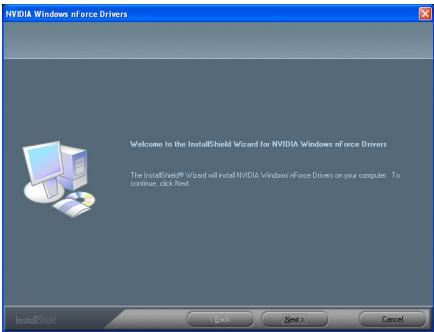
1. Click [Next].
2. Click [Next].
3. Click [Next].
4. Click [Yes].
5. Click [Yes].
![ABIT FATAL1TY-AN8-SLI - Click [Yes]. - 1](/content/2025/01/174533/images/ed0fa9f8ac0cf8f7030ed749e81d1d97a3d8e763878577392b7f8ae9ae09867b.jpg)
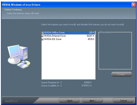
6. Click [Next].
![ABIT FATAL1TY-AN8-SLI - Click [Next]. - 1](/content/2025/01/174533/images/48e70d87786002c58eccf340430f09210894cf576554358c28349b1bd0d5273a.jpg)
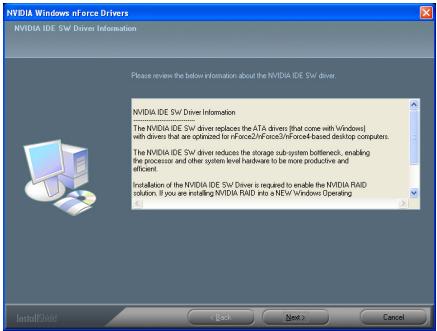
7. Click [Next].
![ABIT FATAL1TY-AN8-SLI - Click [Next]. - 1](/content/2025/01/174533/images/55767887cf30698f3a72bb859db97f0a8da53ee82effc2c39f11827d4336eeb3.jpg)
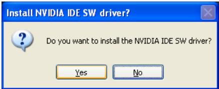
8. Click [Next].
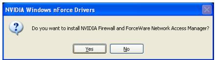
![ABIT FATAL1TY-AN8-SLI - Click [Next]. - 1](/content/2025/01/174533/images/efd6f2e421da32412c82280a730ad414c63f3fb5254a83d06cc9d7127b3a6af1.jpg)
9. Click [Yes].
![ABIT FATAL1TY-AN8-SLI - Click [Yes]. - 1](/content/2025/01/174533/images/fb51fef9b340e4167dafa3548e3f75fa36faf7aac953edbfb175d1a63d66e05d.jpg)
10. Choose [Yes, I want to restart my computer now.], and click [Finish] to complete setup.
Appendix B. Install Realtek Audio Driver
The installation procedures and screen shots in this section are based on Windows XP operating system. For those of other OS, please follow its on-screen instruction.
Insert the Driver & Utility CD into CD-ROM drive, it should execute the installation program automatically. If not, double-click the execution file at the main directory of this CD to enter the installation menu.
After entering the installation menu, move your cursor to [Drivers] tab. Click [Realtek Audio Driver]. The following screen appears.

- Click [Next].
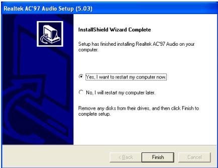
- Choose [Yes, I want to restart my computer now.], and click [Finish] to complete setup.
For more information:
WWW.ABIT.COM.TW
WWW.FATALITY.COM
Appendix C. Install USB 2.0 Driver
NOTE: The installation for USB 2.0 driver for Windows XP or Windows 2000 is currently available by updating the latest Service Pack from Microsoft's web site.
For more information:
WWW.ABIT.COM.TW
WWW.FATALITY.COM
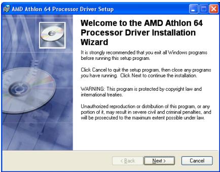
Appendix D. Install AMD64 Processor Driver
The installation procedures and screen shots in this section are based on Windows XP operating system. For those of other OS, please follow its on-screen instruction.
Insert the Driver & Utility CD into CD-ROM drive, it should execute the installation program automatically. If not, double-click the execution file at the main directory of this CD to enter the installation menu.
After entering the installation menu, move your cursor to [Drivers] tab. Click [AMD64 Processor Driver]. The following screen appears.
NOTE: For Windows 2000 operating system, this [AMD64 Processor Driver] button will be replaced by [AMD Cool'n'Quiet Software].
- Click [OK].
- Click [Next].
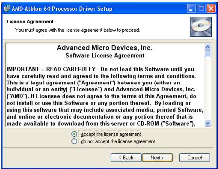
- Check the item "I accept the license agreement". Click [Next] to go on next step.
- Click [Next].
- Click [Next].
6. Click [Next].
7. Click [Finish].
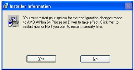
8. Click [Yes] to restart your system.
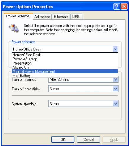
9. After the system restarted, open the "Power Options" from the control panel and choose the power scheme "Minimal Power Management" to enable Cool 'n' Quiet.
NOTE: For Windows 2000 or ME system, an AMD Cool 'n' Quiet tab will appear under "Power Options" when the Cool 'n' Quiet software for Windows 2000 and ME is installed. This must be set to "Automatic Mode" for Cool 'n' Quiet to be enabled.
Appendix E. Install ABIT μGuru Utility
The installation procedures and screen shots in this section are based on the Windows XP operating system. For other operating systems, please follow the on-screen instructions.
Insert the Driver & Utility CD into the CD-ROM drive. It should execute the installation program automatically. If not, double-click the executable file located in the main directory of this CD to enter the installation menu.
After entering the installation menu, move your cursor to the [ABIT Utility] tab. Click [ABIT Guru]. The following screen appears.
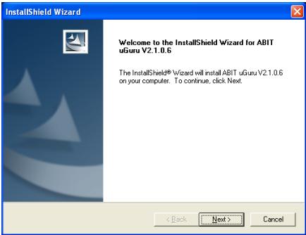
- Click [Next].
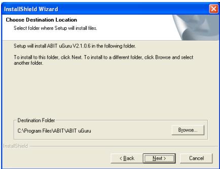
- Click [Next].
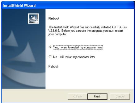
- Click [Finish] to complete setup.
For more information:
WWW.ABIT.COM.TW
WWW.FATALITY.COM
Appendix F. AN8 NVRaid Floppy Disk
If you lost or damaged the SATA Driver Disk that came with the package, use the AN8 NVRaid Floppy Disk to create another one.
The installation procedures and screen shots in this section are based on Windows XP operating system. For those of other OS, please follow its on-screen instruction.
Insert the Driver & Utility CD into CD-ROM drive, it should execute the installation program automatically. If not, double-click the execution file at the main directory of this CD to enter the installation menu.
After entering the installation menu, move your cursor to [ABIT Utility] tab. Click [AN8 NVRaid Floppy Disk]. The following screen appears.
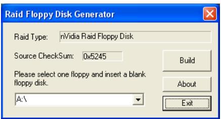
- Insert one blank floppy disk to the selected floppy drive and click [Build].
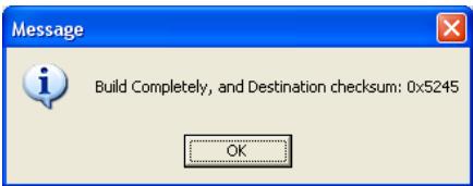
- Click [OK] to finish building the SATA Driver Disk.
For more information:
WWW.ABIT.COM.TW
WWW.FATALITY.COM
Appendix G. POST Code Definition
AWARD POST Code Definition:
| POST (hex) | Description |
| CF | Test CMOS R/W functionality |
| C0 | Early chipset initialization: -Disable shadow RAM -Disable L2 cache (socket 7 or below) -Program basic chipset registers |
| C1 | Detect memory -Auto-detection of DRAM size, type and ECC -Auto-detection of L2 cache (socket 7 or below) |
| C3 | Expand compressed BIOS code to DRAM |
| C5 | Call chipset hook to copy BIOS back to E000 & F000 shadow RAM |
| 01 | Expand the Xgroup codes locating in physical address 1000:0 |
| 03 | Initial Superio_Early_Init switch |
| 05 | 1. Blank out screen 2. Clear CMOS error flag |
| 07 | 1. Clear 8042 interface 2. Initialize 8042 self-test |
| 08 | 1. Test special keyboard controller for Winbond 977 series Super I/O chips 2. Enable keyboard interface |
| 0A | 1. Disable PS/2 mouse interface (optional) 2. Auto detect ports for keyboard & mouse followed by a port & interface swap (optional) 3. Reset keyboard for Winbond 977 series Super I/O chips |
| 0E | Test F000h segment shadow to see whether it is R/W-able or not. If test fails, keep beeping the speaker |
| 10 | Auto detect flash type to load appropriate flash R/W codes into the run time area in F000 for ESCD & DMI support |
| 12 | Use walking 1's algorithm to check out interface in CMOS circuitry. Also set real-time clock power status, and then check for override |
| 14 | Program chipset default values into chipset. Chipset default values are MODBINable by OEM customers |
| 16 | Initial onboard clock generator if Early_Init_Onboard_Generator is defined. See also POST 26. |
| 18 | Detect CPU information including brand, SMI type (Cyrix or Intel) and CPU level (586 or 686) |
| 1B | Initial interrupts vector table. If no special specified, all H/W interrupts are directed to SPURIOUS_INT_HDLR & S/W interrupts to SPURIOUSsoft_HDLR. |
| 1D | Initial EARLY_PM_INIT switch |
| 1F | Load keyboard matrix (notebook platform) |
| 21 | HPM initialization (notebook platform) |
| 23 | 1. Check validity of RTC value: e.g. a value of 5Ah is an invalid value for RTC minute. 2. Load CMOS settings into BIOS stack. If CMOS checksum fails, use default value instead. |
| 24 | Prepare BIOS resource map for PCI & PnP use. If ESCD is valid, take into consideration of the ESCD's legacy information. |
| 25 | Early PCI Initialization: -Enumerate PCI bus number. -Assign memory & I/O resource -Search for a valid VGA device & VGA BIOS, and put it into C000:0 |
| 26 | 1. If Early_Init_Onboard_Generator is not defined Onboard clock generator initialization. Disable respective clock resource to empty PCI & DIMM slots. 2. Init onboard PWM 3. Init onboard H/W monitor devices |
| 27 | Initialize INT 09 buffer |
| 29 | 1. Program CPU internal MTRR (P6 & PII) for 0-640K memory address. 2. Initialize the APIC for Pentium class CPU. 3. Program early chipset according to CMOS setup. Example: onboard IDE controller. 4. Measure CPU speed. |
| 2B | Invoke Video BIOS |
| 2D | 1. Initialize double-byte language font (Optional) 2. Put information on screen display, including Award title, CPU type, CPU speed, full screen logo. |
| 33 | Reset keyboard if Early_Set KB is defined e.g. Winbond 977 series Super I/O chips. See also POST 63. |
| 35 | Test DMA Channel 0 |
| 37 | Test DMA Channel 1. |
| 39 | Test DMA page registers. |
| 3C | Test 8254 |
| 3E | Test 8259 interrupt mask bits for channel 1 |
| 40 | Test 8259 interrupt mask bits for channel 2 |
| 43 | Test 8259 functionality |
| 47 | Initialize EISA slot |
| 49 | 1. Calculate total memory by testing the last double word of each 64K page 2. Program writes allocation for AMD K5 CPU |
| 4E | 1. Program MTRR of M1 CPU 2. Initialize L2 cache for P6 class CPU & program CPU with proper cacheable range 3. Initialize the APIC for P6 class CPU 4. On MP platform, adjust the cacheable range to smaller one in case the cacheable ranges between each CPU are not identical |
| 50 | Initialize USB |
| 52 | Test all memory (clear all extended memory to 0) |
| 53 | Clear password according to H/W jumper (Optional) |
| 55 | Display number of processors (multi-processor platform) |
| 57 | Display PnP logo Early ISA PnP initialization -Assign CSN to every ISA PnP device |
| 59 | Initialize the combined Trend Anti-Virus code |
| 5B | (Optional Feature) Show message for entering AWDFLASH.EXE from FDD (optional) |
| 5D | 1. Initialize Init_Onboard_Super_IO 2. Initialize Init_OnbaordAUDIO |
| 60 | Okay to enter Setup utility; i.e. not until this POST stage can users enter the CMOS setup utility |
| 63 | Reset keyboard if Early_Sett KB is not defined |
| 65 | Initialize PS/2 Mouse |
| 67 | Prepare memory size information for function call: INT 15h ax=E820h |
| 69 | Turn on L2 cache |
| 6B | Program chipset registers according to items described in Setup & Auto-configuration table |
| 6D | 1. Assign resources to all ISA PnP devices 2. Auto assign ports to onboard COM ports if the corresponding item in Setup is set to “AUTO” |
| 6F | 1. Initialize floppy controller 2. Set up floppy related fields in 40:hardware |
| 75 | Detect & install all IDE devices: HDD, LS120, ZIP, CDROM ... |
| 76 | (Optional Feature) Enter AWDFLASH.EXE if: -AWDFLASH is found in floppy drive -ALT+F2 is pressed |
| 77 | Detect serial ports & parallel ports. |
| 7A | Detect & install co-processor |
| 7C | Init HDD write protect |
| 7F | Switch back to text mode if full screen logo is supported -If errors occur, report errors & wait for keys -If no errors occur or F1 key is pressed to continue: Clear EPA or customization logo |
| E8POST.ASM starts | |
| 82 | 1. Call chipset power management hook 2. Recover the text font used by EPA logo (not for full screen logo) 3. If password is set, ask for password |
| 83 | Save all data in stack back to CMOS |
| 84 | Initialize ISA PnP boot devices |
| 85 | 1. USB final Initialization 2. Switch screen back to text mode |
| 87 | NET PC: Build SYSID Structure |
| 89 | 1. Assign IRQs to PCI devices 2. Set up ACPI table at top of the memory. |
| 8B | 1. Invoke all ISA adapter ROMs 2. Invoke all PCI ROMs (except VGA) |
| 8D | 1. Enable/Disable Parity Check according to CMOS setup 2. APM Initialization |
| 8F | Clear noise of IRQs |
| 93 | Read HDD boot sector information for Trend Anti-Virus code |
| 94 | 1. Enable L2 cache 2. Program Daylight Saving 3. Program boot up speed 4. Chipset final initialization. 5. Power management final initialization 6. Clear screen & display summary table 7. Program K6 write allocation 8. Program P6 class write combining |
| 95 | Update keyboard LED & typematic rate |
| 96 | 1. Build MP table 2. Build & update ESCD 3. Set CMOS century to 20h or 19h 4. Load CMOS time into DOS timer tick 5. Build MSIRQ routing table |
| FF | Boot attempt (INT 19h) |
AC2003 POST Code Definition:
| POST (hex) | Description |
| Power On Sequence | |
| 8.1. | Start power on sequence |
| 8.2. | Enable ATX power supply |
| 8.3. | ATX power supply ready |
| 8.4. | DDR voltage ready |
| 8.5. | Setup PWM for CPU core voltage |
| 8.6. | Assert PWM for CPU core voltage |
| 8.7. | Check CPU core voltage |
| 8.8. | CPU core voltage ready |
| 8.9. | Initial clock generator IC |
| 8.A. | North Bridge chipset voltage ready |
| 8.B. | AGP voltage ready |
| 8.C. | 3VDUAL voltage ready |
| 8.D. | VDDA 2.5V voltage ready |
| 8.D. | GMCHVTT voltage ready |
| 8.E. | Check CPU fan speed |
| 8.F. | Assert all power ready |
| 9.0. | Complete uGuru initial processAWARD BIOS take over booting job |
| Power Off Sequence | |
| 9.1. | Start power off sequence |
| 9.2. | De-Assert all power |
| 9.3. | Se-Assert power on |
| 9.4. | De-Assert LDT Bus power |
| 9.5. | De-Assert PWM for CPU core voltage |
| 9.6. | De-Assert CPU core voltage |
| 9.7. | Check CPU core voltage |
| 9.8. | De-Assert ATX power supply |
| 9.9. | Complete power off sequence |
| Others | |
| F.0. | Button reset |
| F.1. | SoftMenu reset |
| F.2. | Power on sequence timeout |
| F.3. | Power off sequence timeout |
NOTE: The decimal point lights up when executing the AC2003 POST action.
For more information:
WWW.ABIT.COM.TW
WWW.FATALITY.COM
Appendix H. Troubleshooting (Need Assistance?)
Q & A:
Q: Do I need to clear the CMOS before I use a new motherboard to assemble my new computer system?
A: Yes, we highly recommend that you clear the CMOS before installing a new motherboard. Please move the CMOS jumper from its default 1-2 position to 2-3 for a few seconds, and then back. When you boot up your system for the first time, follow the instructions in the user's manual to load the optimized defaults.
Q: If my system hangs when I update the BIOS or set the wrong CPU parameters, what should I do?
A: Whenever you update the BIOS or if the system hangs due to wrong CPU parameters setting, always clear CMOS jumper before booting up again.
Q: Why does the system fail to boot up again right after a mechanical power-off?
A: Please keep a 30-second interval between each mechanical power On/Off.
Q: Why does the system fail to boot up and nothing displays on the screen after I did some overclocking or non-standard settings inside the BIOS? Is the motherboard dead? Do I need to return it to where I bought from or go through an RMA process?
A: It should not cause hardware or permanent damage to motherboard when BIOS settings were changed from default to over-clocking or non-standard status.
We suggest the following three troubleshooting methods to discharge CMOS data, recover the hardware default status, making the motherboard work again. There is no need to bother returning the motherboard to where you bought it or go through an RMA process.
Step 1. Switch off the power supply unit and then switch it on again after one minute. If there is no power switch on the power supply unit, disconnect its power cord for one minute and then reconnect.
Press and hold the key to enter the BIOS setup page to apply the correct settings.
If the situation remains the same, repeat the procedures in Step 1 for three times, or try Step 2.
Step 2. Switch off the power supply unit or disconnect the power cord. Open the chassis cover. Locate the CCMOS jumper near the button battery. Change the jumper position from default 1-2 to 2-3 for one minute to discharge the CMOS data, and then put it back to default 1-2 position.
Close the chassis and switch on the power supply unit or plug in the power cord. Press the power-on button to boot up system. If it works, hit key to enter the BIOS setup page to do the correct settings.
If the situation remains the same, try Step 3.
Step 3. The same procedure as Step 2, but while discharging the CMOS data, pull out the ATX power connectors from motherboard and remove the button battery during CMOS discharge.
Q: How can I get a quick response to my request for technical support?
A: Be sure to follow the guidelines as stated in the "Technical Support Form" section of this manual.
If you have a problem during operation, in order to help our technical support personnel quickly determine the problem with your motherboard and give you the answers you need, eliminate any peripheral that is not related to the problem, and indicate it on the form. Fax this form to your dealer or to the company where you bought the hardware in order to receive prompt technical support. (You can refer to the examples given below)
Example 1:
With a system including: motherboard (with CPU, DRAM...) HDD, CD-ROM, FDD, VGA CARD, MPEG CARD, SCSI CARD, SOUND CARD, etc., if you cannot boot up after the system is assembled, check the key components of the system using the procedure described below. First remove all interface cards except the VGA card and try to reboot.
If you still cannot boot up: Try installing another brand/model VGA card and see if the system will start. If it still does not start, note the VGA card model, motherboard model, Bios identification number, and CPU on the technical support form (refer to main instructions), and describe the problem in the space provided.
If you can boot up: Insert the interface cards you have removed back into the system one by one, and try to start the system each time you insert a card until the system will not start. Keep the VGA card and the interface card that caused the problem inserted on the motherboard, remove any other cards or peripheral, and start again. If you still cannot start, note the information related to both cards in the add-on Card space provided, and don't forget to indicate the motherboard model, version, BIOS identification number, CPU (refer to main instructions), and give a description of the problem.
Example 2:
With a system including the motherboard (with CPU, DRAM...) HDD, CD-ROM, FDD, VGA CARD, LAN CARD, MPEG CARD, SCSI CARD, SOUND CARD, after assembly and after having installed the sound card driver, when you restart the system, it resets automatically when it runs the sound card Driver.. This problem may be due to the sound card driver. During the Starting DOS... procedure, press SHIFT (BY-PASS) key, to skip CONFIG.SYS and AUTOEXEC.BAT; edit CONFIG.SYS with a text editor, and in line that loads the sound card driver, add a remark REM, in order to disable the sound card driver. See the example below.
CONFIG.SYS:
DEVICE=C:\DOS\HIMEM.SYS
DEVICE=C:\DOS\EMM386.EXE HIGHSCAN
DOS=HIGH, UMB
FILES=40
BUFFERS=36
REM DEVICEHIGH=C:\PLUGPLAY\DWCFGMG.SYS
LASTDRIVE = Z
Restart the system. If the system starts and does not reset, you can be sure that the problem is due to the sound card driver. Write down the sound card model, motherboard model, BIOS identification number on the technical support file (refer to main instructions), and describe the problem in the space provided.
We will show you how to fill the "Technical Support Form".
Main instructions:
To fill in this "Technical Support Form", refer to the step-by-step instructions given below:
1*.MODEL: Note the model number given in your user's manual.
Example: Fatal1ty AN8 SLI
2. Motherboard model number (REV): Note the motherboard model number labeled on the motherboard as "REV:.***".
Example: REV: 1.0
-
BIOS ID and Part Number: See the on screen message.
-
DRIVER REV: Note the driver version number indicated on the DEVICE DRIVER disk (if any) as "Release .". For example:
5*. OS/APPLICATION: Indicate the operating system and applications you are running on the system.
Example: MS-DOS 6.22
Windows® 98 SE, Windows® 2000, etc....
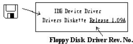
6^ .CPU:Indicate the brand and the speed (MHz) of your CPU.
Example:(A) In the "Brand" space, write "Intel"; in the "Specifications" space, write "Pentium® 4 1.9GHz".
- HDD: Indicate the brand and specifications of your HDD(s); specify if the HDD is using IDE1 or IDE2. If you know the disk capacity, indicate it and check ("✓") "□"; in case you give no indication, we will consider that your HDD is "IDE1" Master.
Example: In the "HDD" space, check the box; in the Brand space, write "Seagate"; in the Specifications space, write "ST31621A (1.6GB)".
- CD-ROM Drive: Indicate the brand and specifications of your CD-ROM drive. Specify if it uses IDE1 or IDE2, and check ( ) "□"; in case you give no indication, we will consider that your CD-ROM is "IDE2" Master.
Example: In the "CD-ROM drive" space, check the box, in the Brand space, write "Mitsumi", in the Specifications space, write "FX-400D".
- System Memory (DDR SDRAM): Indicate the brand and specifications (DDR DIMM) of your system memory. Such as Density, Description, Module Components, Module Part Number, CAS Latency, and Speed (MHz).
For example: In the Brand space, write "Micron"; in the Specifications space, write: Density: 128MB, Description: SS 16 Megx72 2.5V ECC Gold, Module Components: (9) 16 Megx 8, Module Part Number: MT9VDDT1672AG, CAS Latency: 2, Speed (MHz): 200 MHz.
Please give us the detailed information of your DDR SDRAM module; it will help us to simulate the problems you met.
- ADD-ON CARD: Indicate which add-on cards you are absolutely sure are related to the problem.
If you cannot identify the problem's origin, indicate all the add-on cards inserted into your system.
NOTE: Items between the “*” are absolutely necessary.

Technical Support Form

Company Name:

Phone Number:

Contact Person:

Fax Number:

E-mail Address:
| Model | * | BIOS ID # | * |
| Motherboard Model No. | DRIVER REV | ||
| OS/Application | * | ||
| Hardware Name | Brand | Specifications | |
| CPU | * | ||
| HDD IDE1IDE2 | |||
| CD-ROM-Drive IDE1IDE2 | |||
| System Memory | |||
| ADD-ON CARD | |||
Problem Description:
Appendix I. How to Get Technical Support
(From our website) http://www.abit.com.tw
(In North America) http://www.ubit-usa.com
(In Europe) http://www.abit.nl
Thank you for choosing Fatality products by ABIT. ABIT sells all our products through distributors, resellers and system integrators; we have no direct sales to end-users. Before sending email for tech support please check with your resellers or integrators if you need any services, they are the ones who sold you your system and they should know best as to what can be done, how they serve you is a good reference for future purchases.
We appreciate every customer and would like to provide the best service to you. Providing fast service to our customers is our top priority. However we receive many phone calls and a huge amount of email from all over the world. At the present time it is impossible for us to respond to every single inquiry.
We have done many compatibility tests and reliability tests to make sure our products have the best quality and compatibility. In case you need service or technical support, please understand the constraints that we have and always check with the reseller who sold the product to you first.
To expedite service, we recommend that you follow the procedures outlined below before contacting us. With your help, we can meet our commitment to provide the best service to the greatest number of ABIT Fatal1ty customers:
- Check the Manual. It sounds simple but we have taken a lot of care in making a well-written and thorough manual. It is full of information that doesn't only pertain to motherboards. The CD-ROM included with your board will have the manual as well as drivers. If you don't have either one, go to our Program Download area of the website or our FTP server.
- Download latest BIOS, software or drivers. Please go to our Program Download area on our website to check to see if you have the latest BIOS. They are developed over periods of time to fix bugs or incompatibilities. Also please make sure you have the latest drivers from your peripheral card makers!
-
Check the ABIT Technical Terms Guide and FAQ on our website. We are trying to expand and make the FAQs more helpful and information rich. Let us know if you have any suggestions. For hot topics, check out our HOT FAQ!
-
Internet Newsgroups. These are a great source of information and many people there can offer help. ABIT's Internet News group, alt.comp.periphs.mainboard.abit, is an ideal forum for the public to exchange information and discuss experiences they have had with ABIT products. Many times you will see that your question has already been asked before. This is a public Internet news group and it is reserved for free discussions. Here is a list of some of the more popular ones:
alt.comp.perips.mainboard.abit comp.sys.ibm.pc.hardware.chips alt.comp.hardware.overclocking alt.comp.hardware.homebuilt alt.comp.hardware.pc-homebuilt
- Fatality - You can find out all about Fatality, ABIT Fatality Products and other Fatality products on Fatality's own website: www.fatality.com.
- ABITGamer.com - Built for gamers, by gamers, ABITGamer.com is ABIT's exclusive online gaming community. It's a place where gamers come to discuss the latest games, participate in gaming events, and meet other gamers around the world. ABITGamer.com also acts as ABIT's gaming portal, allowing users to find out the latest on ABIT Fatal1ty gaming hardware, ABIT Fatal1ty Shootouts, and ACON Gaming Tournaments. Registration is fast and free. For more information, visit www.abitgamer.com.
- Ask your reseller. Your ABIT authorized distributor should be able to provide the fastest solution to your technical problem. We sell our products through distributors who sell to resellers and stores. Your reseller should be very familiar with your system configuration and should be able to solve your problem much more efficiently than we could. After all, your reseller regards you as an important customer who may purchase more products and who can urge your friends to buy from him or her as well. They integrated and sold the system to you. They should know best what your system configuration is and your problem. They should have reasonable return or refund policies. How they serve you is also a good reference for your next purchase.
- Contacting ABIT. If you feel that you need to contact ABIT directly you can send email to the ABIT technical support department. First, please contact the support team for the branch office closest to you. They will be more familiar with local conditions and will have better insight as to which resellers offer what products and services. Due to the huge number of emails coming in every day and other reasons, such as the time required for problem reproduction, we will not be able to reply to every email. Please understand that we are selling through distribution channels and while we don't have the resources to serve every end-user, we will do our best to help every customer. Please also remember that for many of our technical support team English is a second language. You will have a better chance of getting a helpful answer if your question can be quickly understood. Be sure to use very, simple, concise language that clearly states the problem, avoid rambling or flowery language, and always list your system components and operating system. Here is the contact information for our branch offices:
| North America and South America | ABIT Computer (U.S.A.) Corporation 45531 Northport Loop West, Fremont CA, 94538, U.S.A. Tel: 1-510-623-0500 Fax: 1-510-623-1092 Sales: sales@abit-usa.com Latin America Sales: ventas@abit-usa.com Marketing: marketing@abit-usa.com Web Site: http://www.ubit-usa.com RMA Center: http://rma.abit-usa.com/ |
| UK and Ireland | ABIT Computer (U.K.) Corporation Ltd. Unit 3, 24-26 Boulton Road, Stevenage, Herts SG1 4QX, UK Tel: 44-1438-228888 Fax: 44-1438-226333 E-mail: sales@abitcomputer.co.uk |
| Germany and Benelux (Belgium, Netherlands, Luxembourg), France, Italy, Spain, Portugal, Greece, Denmark, Norway, Sweden, Finland, and Switzerland | AMOR Computer B.V. (ABIT's European Office) Jan van Riebeeckweg 15, 5928LG, Venlo, The Netherlands Tel: 31-77-3204428 Fax: 31-77-3204420 Sales: sales@abit.nl Web Site: http://www.ubit.nl |
| Austria, Czech, Romania, Bulgaria, Slovakia, Croatia, Bosnia, Serbia, and Macedonia | Asguard Computer Ges.m.b.H Schmalbachstrasse 5, A-2201 Gerasdorf / Wien, Austria Tel: 43-1-7346709 Fax: 43-1-7346713 E-mail: asguard@asguard.at |
| Shanghai | ABIT Computer (Shanghai) Co. Ltd. Tel: 86-21-6235-1829 Fax: 86-21-6235-1832 Web Site: http://www.ubit.com.cn |
| Russia and CIS | ABIT Computer (Russia) Co. Ltd. Sales: sales@abit.ru Info: info@abit.ru Web Site: http://www.ubit.ru |
| Poland | ABIT Computer (Poland) Co. Ltd. Przedstawicielstwo w Polsce ul. Wita Stwosza 28, 50-149 Wroclaw Tel: 48 71 780 78 65 / 66 Fax: 48 71 372 30 87 |
| Japan | Web Site: http://www.ubit4u.jp |
| Taiwan Head Office (Serving all other territories not listed above. Taiwan is 8+ GMT time, and may have different holiday calendar from yours.) | ABIT Computer Corporation No. 323, Yang Guang St., Neihu, Taipei, 114, Taiwan Tel: 886-2-8751-8888 Fax: 886-2-8751-3382 Sales: sales@abit.com.tw Marketing: market@abit.com.tw Web Site: http://www.ubit.com.tw |
- RMA Service. If your system has been working but it just stopped, but you have not installed any new software or hardware recently, it is likely that you have a defective component. Please contact the reseller from whom you bought the product. You should be able to get RMA service there.
- Reporting Compatibility Problems to ABIT. Because of the tremendous number of email messages we receive every day, we are forced to give greater weight to certain types of messages than to others. For this reason, any compatibility problem that is reported to us, giving detailed system configuration information and error symptoms will receive the highest priority. For the other questions, we regret that we may not be able to reply directly. But your questions may be posted to the Internet news group in order that a larger number of users can have the benefit of the information. Please check the news group from time to time.
Thank You
ABIT Computer Corporation
WWW.ABIT.COM.TW
Johnathan "Fatality" Wendel
WWW.FATALITY.COM
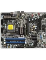

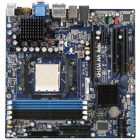
- Copyright and Warranty Notice
- Table of Contents
- Chapter 1. Introduction 1-1
- Chapter 2. Hardware Setup 2-1
- Chapter 3. BIOS Setup 3-1
- Chapter 1. Introduction
- 1-1. Fatality
- FATALITY STORY
- GOING PRO
- WINNING STREAK
- LIVIN' LARGE
- ADREAM
- FATALITY BRAIN TRUST
- 1-2. Features & Specifications
- CPU
- Chipset
- NVIDIA SLI Technology
- Memory
- ABIT Engineered
- NV SATA RAID
- NV GbE LAN
- NV Firewall
- 9.IEEE1394
- Audio
- Internal I/O Connectors
- Back Panel I/O
- Miscellaneous
- 1-3. Layout Diagram
- Chapter 2. Hardware Setup
- 2-1. Install The Motherboard
- 2-2. Install CPU, Heatsink and Fan Assembly
- 2-3. Install System Memory
- 2-4. Install two Graphics Cards with NVIDIA SLI Technology
- 2-5. Connectors, Headers and Switches
- (1).ATX Power Input Connectors
- (2). FAN Power Connectors
- (3). CMOS Memory Clearing Header
- (4). Front Panel Switches & Indicators Headers
- (5). Additional USB Port Headers
- (6). Additional IEEE1394 Port Headers
- (7). Wake-up Header
- (8). GURU Panel Connection Header
- (9). Floppy and IDE Disk Drive Connectors
- (10). Serial ATA Connectors
- (11). Status Indicators
- (12). POST Code Display
- (13). PCI Express x1 Slots
- (14). PCI Express x16 Slot
- (15). SLI Switchboard Slot
- (16). AUDIOMAX Slot
- NOTE: Install this daughter-card at slot "AUDIOMAX1".
- - S/PDIF Output Connection:
- - S/PDIF Input Connection:
- Line-in connection:
- Analog connection for 7.1 channel audio system:
- (17). Front Panel Audio Connection Header
- (18). Internal Audio Connectors
- Chapter 3. BIOS Setup
- PRESS DEL TO ENTER SETUP
- 3-1. μGuru™ Utility
- OC Guru:
- Brand Name:
- Frequency:
- CPU Operating Speed:
- User Define:
- External Clock:
- \* Multiplier Factor:
- PCIE Clock
- Voltages Control:
- \* CPU Core Voltage:
- \* DDR SDRAM Voltage:
- \* DDR VTT Voltage:
- \* nForce4 Voltage:
- \* HyperTransport Voltage:
- DDR Ref Voltage:
- CPU Ref Voltage:
- Power Cycle Statistics:
- ABIT EQ:
- ABIT EQ Beep Control:
- Temperature Monitoring:
- CPU Temperature/System Temperature/PWM Temperature:
- \* Shutdown Enable:
- \* Shutdown Temp.:
- \* Beep Enable:
- \* Beep Temp.:
- Voltage Monitoring:
- All Voltages:
- * High/Low Limit:
- Fan Speed Monitoring:
- CPU/NB/SYS/OTES1/OTES2/AUX FAN Speed:
- \* Low Limit:
- CPU/NB/SYS/OTES1/OTES2/AUX FanEQ Control:
- \* Reference Temperature:
- * Control Temperature High/Low:
- DC Fan Voltage High/Low:
- 3-2. Standard CMOS Features
- Date (mm:dd:yy):
- Time (hh:mm:ss):
- IDE HDD Auto-Detection:
- IDE Channel 1 Master/Slave, IDE Channel 2 Master/Slave, IDE Channel 3 Master, IDE Channel 4 Master, IDE Channel 5 Master, IDE Channel 6 Master:
- Access Mode:
- Capacity:
- Cylinder:
- Head:
- 3-3. Advanced BIOS Features
- Removable Device Priority:
- Hard Disk Boot Priority:
- CD-ROM Boot Priority:
- First Boot Device / Second Boot Device / Third Boot Device / Boot Other Device:
- Swap Floppy Drive:
- Boot Up Floppy Seek:
- Boot Up NumLock Status:
- Security Option:
- MPS Version Ctrl For OS:
- Delay For HDD (Secs):
- Full Screen LOGO Show:
- Disable unused PCI Clock:
- 3-4. Advanced Chipset Features
- HT Frequency:
- HT Width:
- DRAM Configuration:
- DRAM Timing Selectable:
- \* DRAMClock:
- CAS Latency Time:
- \* Row Cycle Time:
- \* Row Refresh Cycle Time:
- \* RAS# to CAS# Delay:
- RAS# to RAS# Delay:
- \* Min. RAS# Active Time:
- RAS# Precharge Time:
- \* Write Recovery Time:
- \* Write to Read Delay:
- DRAM Command Rate:
- \* Burst Length
- Bank Interleaving:
- bit Dram Memory Hole:
- MTRR mapping mode
- Back to Advanced Chipset Features Setup Menu:
- SSE/SSE2 Instructions:
- System BIOS Cacheable:
- 3-5. Integrated Peripherals
- Onchip PCI Device
- USB Controller:
- * USB Memory Type:
- USB Keyboard Support:
- USB Mouse Support:
- LAN Controller:
- LAN Boot ROM:
- IDE/RAID Function
- IDE Function Setup:
- Onboard IDE-1 Controller / Onboard IDE-2 Controller:
- IDE DMA transfer access:
- Serial-ATA 1/Serial ATA 2:
- SATA DMA transfer/SATA 2 DMA transfer:
- IDE Prefetch Mode:
- RAID Config:
- RAID Enable:
- Back to Integrated Peripherals Setup Menu:
- Init Display First:
- Onboard IEEE1394 Controller:
- 3-6. Power Management Setup
- ACPI Suspend Type:
- USBResumefromS3:
- Power Button Function:
- Wakeup by PME# of PCI:
- Wake-Up by OnChip LAN:
- Wake-Up by Alarm:
- * Date (of Month) Alarm/ Time (hh:mm:ss) Alarm:
- Cool 'n' Quiet Technology:
- Power On Function:
- KB Power On Password:
- Hot Key Power On:
- Restore on AC Power Loss:
- 3-7. PnP/PCI Configurations
- Resources Controlled By:
- IRQ Resources:
- Back to PnP/PCI Configurations Setup Menu:
- PCI/VGA Palette Snoop:
- PIRQ_0 Use IRQ No. ~PIRQ 3 Use IRQ No.:
- Maximum Payload Size:
- 3-8. Load Fail-Safe Defaults
- 3-9. Load Optimized Defaults
- 3-10. Set Password
- 3-11. Save & Exit Setup
- 3-12. Exit Without Saving
- Appendix A. Install nVidia nForce Chipset Driver
- Click [Yes].
- Click [Next].
- Click [Next].
- Click [Next].
- Click [Yes].
- Choose [Yes, I want to restart my computer now.], and click [Finish] to complete setup.
- Appendix B. Install Realtek Audio Driver
- Appendix C. Install USB 2.0 Driver
- Appendix D. Install AMD64 Processor Driver
- Appendix E. Install ABIT μGuru Utility
- Appendix F. AN8 NVRaid Floppy Disk
- Appendix G. POST Code Definition
- Appendix H. Troubleshooting (Need Assistance?)
- Q & A:
- Q: How can I get a quick response to my request for technical support?
- Example 1:
- Example 2:
- Main instructions:
- Technical Support Form
- Appendix I. How to Get Technical Support
- Thank You
- ABIT Computer Corporation
- WWW.ABIT.COM.TW
- Johnathan "Fatality" Wendel
- WWW.FATALITY.COM
Brand : ABIT
Model : FATAL1TY-AN8-SLI
Category : Motherboard