
E 4 - Inverter INFOSEC - Free user manual and instructions
Find the device manual for free E 4 INFOSEC in PDF.

User questions about E 4 INFOSEC
0 question about this device. Answer the ones you know or ask your own.
Ask a new question about this device
Download the instructions for your Inverter in PDF format for free! Find your manual E 4 - INFOSEC and take your electronic device back in hand. On this page are published all the documents necessary for the use of your device. E 4 by INFOSEC.
USER MANUAL E 4 INFOSEC
English Version. p.43

Version Française
SOMMAIRE
1 INSTRUCTIONS DE SECURITE 6
1.1 TRANSPORT 6
1.2 MISE EN PLACE 6
1.3 INSTALLATION 6
1.4 FONCTIONNEMENT 7
1.5 MAINTENANCE,APRES-VENTE ET DEAUTS 7
2 DESCRIPTION DES PICTOGRAMMES UTILISES 9
3 INTRODUCTION - E ^4 700(S)/1000(S)/2000(S)/3000(S) 10
4 DESCRIPTION DU SYSTEME 11
5 RACCORDEMENT ET MISE EN SERVICE DES ONDULEURS E4 700/1000(S)/2000(S)/3000(S) 1 2
5.1 INSPECTION & CONTROLLE DU DEBALLAGE 12
5.2 RACCORDEMENT: 12
5.3 BRANCHEMENT DES PC. 13
5.4 CHARGE DES BATTERIES 13
5.5 MISE EN MARCHE DE L'ONDULEUR 14
5.6 TESTS DE FONCTIONNEMENT 14
5.7 ETEINDRE L'ONDULEUR 14
5.8 RACCORDEMENT D'UNE ARMOIRE BATTERIE EXTERNE SUR LE MODELE LONGUE AUTONOMIE (S) 15
6 INCIDENTS DE FONCTIONNEMENT 16
7 MAINTENANCE 17
7.1 FONCTIONNEMENT 17
7.2 STOCKAGE 17
8 CHARACTERISTIQUES TECHNIQUES 18
8.1 SPECIFICATIONS ELECTRIQUES 18
8.2 ENVIRONNEMENT RECOMMANDE 18
8.3 AUTONOMIE TYPIQUE (MODE BATTERIE) 18
8.4 DIMENSIONS ET POIDS 19
9 INTRODUCTION - E^4 5000(S)/6000(S)/10000(S) 20
9.1 SPECIFICATIONS GENE RALES 20
9.2 PERFORMANCE ELECTRIQUE 20
9.3 ENVIRONNEMENT RECOMMANDÉ 20
10 INSTALLATION 21
10.1 INSPECTION & CONTROLLE LORS DU DEBALLAGE 21
10.2 RACCORDEMENT 21
10.3 RACCORDEMENT D'UNE BATTERIE EXTERNE SUR LE MODELE LONGUE AUTONOMIE(S) 23
10.4 FONCTIONNEMENT EN PARALLELE 24
11 MODE DE FONCTIONNEMENT 25
11.1 FONCTIONNEMENT ET MAINTENANCE 25
11.2 MISE EN MARCHE (MODE NORMAL) 25
11.3 DECONNECTIOND'UN ONDULEUR 27
11.4 MISE EN GARDE POUR LES SYSTEMES EN PARALLELE 28
12 MAINTENANCE BATTERIE 29
13 PRECAUTIONS POUR LE REMPLACEMENT DE LA BATTERIE 30
14 INCIDENTS DE FONCTIONNEMENT 31
15 MODE DE FONCTIONNEMENT POUR TOUS LES MODELES 3 3
15.1 MODE SECTEUR 33
15.2 MODE BATTERIE 33
15.3 MODE BY-PASS 34
15.4 MODE ANOMALIE 34
16 PORT DE COMMUNICATION 35
16.1 INTERFACERS232 35
16.2 INTERFACE AS400 (OPTION) 35
17LOGICIELPOURTOUSLESMODELES 36
17.1 LOGICIEL UPSURF-CONTROL 36
17.2 PROCEDURES D'INSTALLATION: 36
18 ANNEXE 1 - SCHEMA DE MONTAGE SYSTEME PARALLELE 37
19 ANNEXE 2 - PANNEAU D'AFFICHAGE (E4 5000/6000/10000) 38
20 ANNEXE 3 - ETAT DES VOYANTS (E4 5000/6000/10000) 39
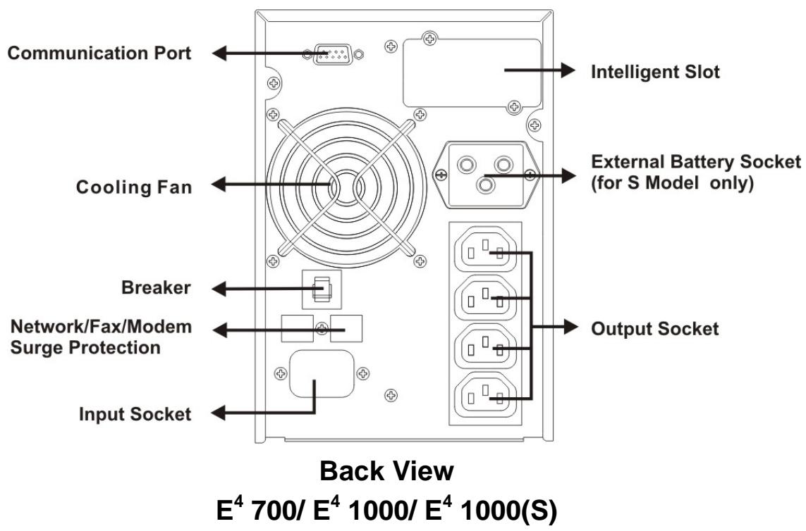
21 ANNEXE 4 - PANNEAU ARRIERE 40

VEUILLEZ LIRE ATTENTIVEMENT CE MANUEL D'UTILISATION ET LES INSTRUCTIONS DE SECURITE AVANT DE METTRE L'ONDULEUR EN SERVICE!
1.1 Transport
1 SAFETY INSTRUCTIONS 46
1.1 Transport 46
1.2 Set-up 46
1.3 Installation 46
1.4 Operation 47
1.5 Maintenance, servicing and faults 47
2 DESCRIPTION OF COMMONLY USED NOTATIONS 49
3 INTRODUCTION - E4 700(S)/1000(S)/2000(S)/3000(S) 50
4 SYSTEM DESCRIPTION 51
5 CONNECTION AND OPERATION: E4 700/1000(S)/2000(S)/3000(S) 5 2
5.1 Control 52
5.2 Wiring 52
5.3 Computer Connection 53
5.4 Battery Charge 53
5.5 Turn On the UPS 54
5.6 Test Function 54
5.7 Turn Off the UPS 54
5.8 Operation procedure of external battery for long backup time Model (S) 5 5
6 TROUBLE SHOOTING 56
7 MAINTENANCE 57
7.1 Operation 57
7.2 Storage 57
8 TECHNICAL DATA 58
8.1 Electrical specifications 58
8.2 Operating Environment 58
8.3 Typical stored energy time: 58
8.4 Dimensions and weights 59
9 INTRODUCTION - E ^4 5000(S)/6000(S)/10000(S) 60
9.1 General specifications 60
9.2 Electrical Performance 60
9.3 Operating Environment 60
10 INSTALLATION 61
10.1 Unpacking and control 61
10.2 Wiring 61
10.3 Operating procedure for connecting the long backup time model UPS with the external battery... 6 3
10.4 Parallel operation 64
For transportation only use the original packaging (to protect against shock and impact).
1.2 Set-up
Condensation may occur if the UPS system is moved directly from a cold to a warm environment. The UPS system must be absolutely dry before being installed. Please allow an acclimatization time of at least two hours.
Do not install the UPS system near water or in damp environments.
Do not install the UPS system where it would be exposed to direct sunlight or near heat.
Do not block up ventilation openings in the UPS system's housing.
Ensure that no fluids or other foreign objects can enter the UPS system.
UPS can work at ambient temperature between 0^ and 40^ . Optimum temperature of working for UPS and batteries are between 20^ and 25^ . In these conditions batteries life is between 3 to 5 years. If temperature is 30^ , life is reduced by half.
1.3 Installation
Do not connect appliances or items of equipment which would overload the UPS system (e.g. laser printers).
Do not connect to the UPS domestic appliances such as a hairdrier, an electric heater, a vacuum cleaner or a drill.
Place cables in such a way that no one can step on or trip over them. Please use only VDE-tested, CE-marked mains cable (e.g. the mains cable of your computer) to connect the UPS system to the building wiring outlet and to connect the loads to the UPS system.
Connect the UPS system only to an earthed shockproof outlet. Please refer to section 5: “Connection and operation”. The building wiring outlet must be easily accessible and close to the UPS system. The UPS can be used by any individuals with no previous experience.
1.3.1 Installation for E^4 700/1000(S)/2000(S)/3000(S)
When installing the equipment, make sure the sum of the leakage current of the UPS and the connected equipment does not exceed 3.5mA .

CAUTION - This is a product for restricted sales distribution to informed partners.
Installation restrictions or additional measures may be needed to prevent disturbances.
An accessible disconnect device shall be incorporated in the building installation wiring and must be close to the UPS system.
This equipment is permanently powered and only qualified maintenance personnel may carry out the installation.
1.4 Operation
Do not disconnect the UPS mains cable while operating: it would cancel the protective earthing of the UPS system which would be harmful to the protection of all connected loads.
The UPS system features its own, internal current source (batteries). The UPS output outlets or output terminals block may be electrically live even if the UPS system is not connected to the building wiring outlet.
In order to fully disconnect the UPS system first press the Standby switch and then disconnect the mains lead.
1.5 Maintenance, servicing and faults
The UPS system operates with hazardous voltages. Repairs have to be carried out only by qualified maintenance personnel.

CAUTION - Risk of electric shock. Even when the UPS is not connected to the mains,
components inside the UPS system are still connected to the battery and are still electrically live and dangerous.

Before carrying out any kind of servicing and/or maintenance, disconnect the batteries and
check that there is no current or no hazardous voltage existing in the terminals of high capability capacitor such as BUS-capacitors.
Only qualified technicians familiar with batteries and with the required precautionary measures may replace batteries and supervise the process. Unauthorized persons must be kept well away from the batteries.

CAUTION - Risk of electric shock. The battery circuit is not isolated from the input voltage.
Hazardous voltages may occur between the battery terminals and the ground. Before touching, please check there is no voltage!
Batteries may cause electric shock and have a high short-circuit current. Please follow precautions specified here below when working with batteries:
- remove watches, rings and any other metal objects
- use only tools with insulated grips and handles.
Install same number and same type of batteries when replacing batteries.
Do not attempt to dispose of batteries by burning them. This could cause battery explosion.
Do not open or destroy batteries. Escaping electrolyte can cause injury to the skin and eyes. It may be toxic.
Please replace the fuse only by the same type of fuse with the same amperage in order to avoid fire hazards.
Do not dismantle the UPS system.
2 Description of commonly used notations
The following notations may be used in this manual and may appear in your application process. Therefore, all users should be familiar with them and understand their explanations.
| Notation and Explanation | |
| Notation | Explanation |
| △ | Alert you to pay special attention |
| △ | Caution of high voltage |
| | | Turn on the UPS |
| ○ | Turn off the UPS |
| ∅ | Idle or shut down the UPS |
| ~ | Alternating current source (AC) |
| --- | Direct source current (DC) |
| ⊕ | Protective ground |
| □ | Alarm silence |
| ⊗ | Overload indication |
| + | Battery check |
| Recycle | |
| × | Keep UPS in a clear area |
The E4 On-Line-Series is an Uninterruptible Power Supply incorporating double-converter technology. It provides perfect protection specifically for Novell, Windows NT and UNIX servers.
The double-converter principle eliminates all power disturbances from the mains. A rectifier converts the alternating current from the outlet to direct current. This direct current charges the batteries and powers the inverter. From this DC voltage the inverter generates a sinusoidal AC voltage which permanently supplies the loads.
Computers and devices are thus powered entirely by the same source of power. In the event of power failure, the maintenance-free batteries power the inverter.
Chapters 4, 5, 6, 7 and 8 take UPS Models into account. UPS Models are listed here below:
| 6. Model No. | 6. Type | 6. Model No. | 6. Type |
| 6. E4 700 | 6. Standard | 6. | Long backup time |
| 6. E4 1000 | 6. E4 1000S | ||
| 6. E4 2000 | 6. E4 2000S | ||
| 6. E4 3000 | 6. E4 3000S |

| Switch | Function |
| ON | To turn on UPS system: press the ON-Switch "I". To deactivate the audible alarm: press the ON-Switch "I". |
| OFF | When mains power is normal, the UPS system switches to Bypass and the inverter is off. The output outlets are supplied with voltage via the bypass if the mains power is available. |
| LEDs | Function |
| LINE LED | The green "LINE" led lights up if mains voltage is applied to the UPS input. "LINE" led blinks when the line and neutral conductor have been reversed at the input of the UPS system. If "LINE" led and "BATTERY" led light up, the mains power supply is out of tolerance. |
| BATTERY LED | The orange-coloured "BATTERY" led lights up when the mains power has failed and the inverter is being powered by the batteries. |
| BYPASS LED | The orange-coloured "BYPASS" led lights up when the UPS system is supplying voltage provided by the mains power via the bypass. |
| INVERTER LED | The green-coloured "INVERTER" led lights up if the UPS system is supplying voltage provided by the mains power via the inverter. |
| FAULT LED | The red "FAULT" led lights up and an audible alarm beeps continuously when the UPS system is in fault condition. Press the "OFF" switch in order to turn off the alarm. |
| LOAD and BATTERY CAPACITY LEDs | These leds show the load of the UPS system if the mains power is available (normal operation): 2nd LED = 96%-105 % -3rd LED = 76%-95 % -4th LED = 56%-75 % -5th LED = 36%-55 % -6th LED = 1-35 % In the battery operation, the LEDs indicate the capacity of the batteries: 2nd LED = 1-35 % -3rd LED = 36%-55 % -4th LED = 56%-75 % -5th LED = 76%-95 % -6th LED = 96%-100 % |

The system has to be installed and wired only by qualified electricians in accordance with
safety regulations!
- When installing the electrical wiring, please note the nominal amperage of your incoming feeder.
5.1 Control
Inspection: when you receive your equipment, check out the packaging carton and its contents to make sure there is no damage. Please inform immediately the carrier if you should find signs of damage.
Please keep the packaging in a safe place for future use.
Note: Please make sure the incoming feeder is isolated and secured to prevent it from being switched back on again.
5.2 Wiring
5.2.1 UPS Input Connection
If the UPS is connected via the power cord, please use a proper outlet with protection against electric power cuts and pay attention to the capacity of the outlet: over 10A for E^4 1000(S) & 2000 and over 16A for E^4 2000(S) & 3000(S).
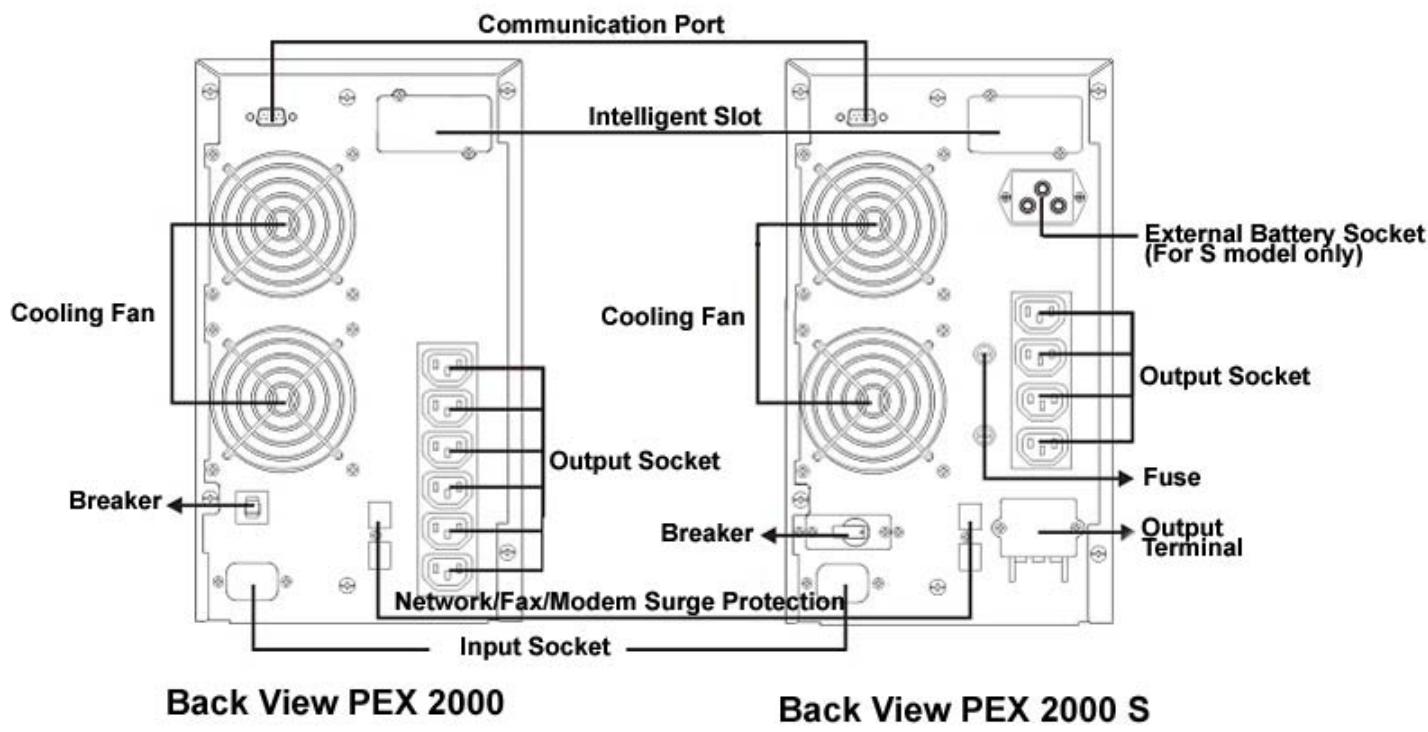
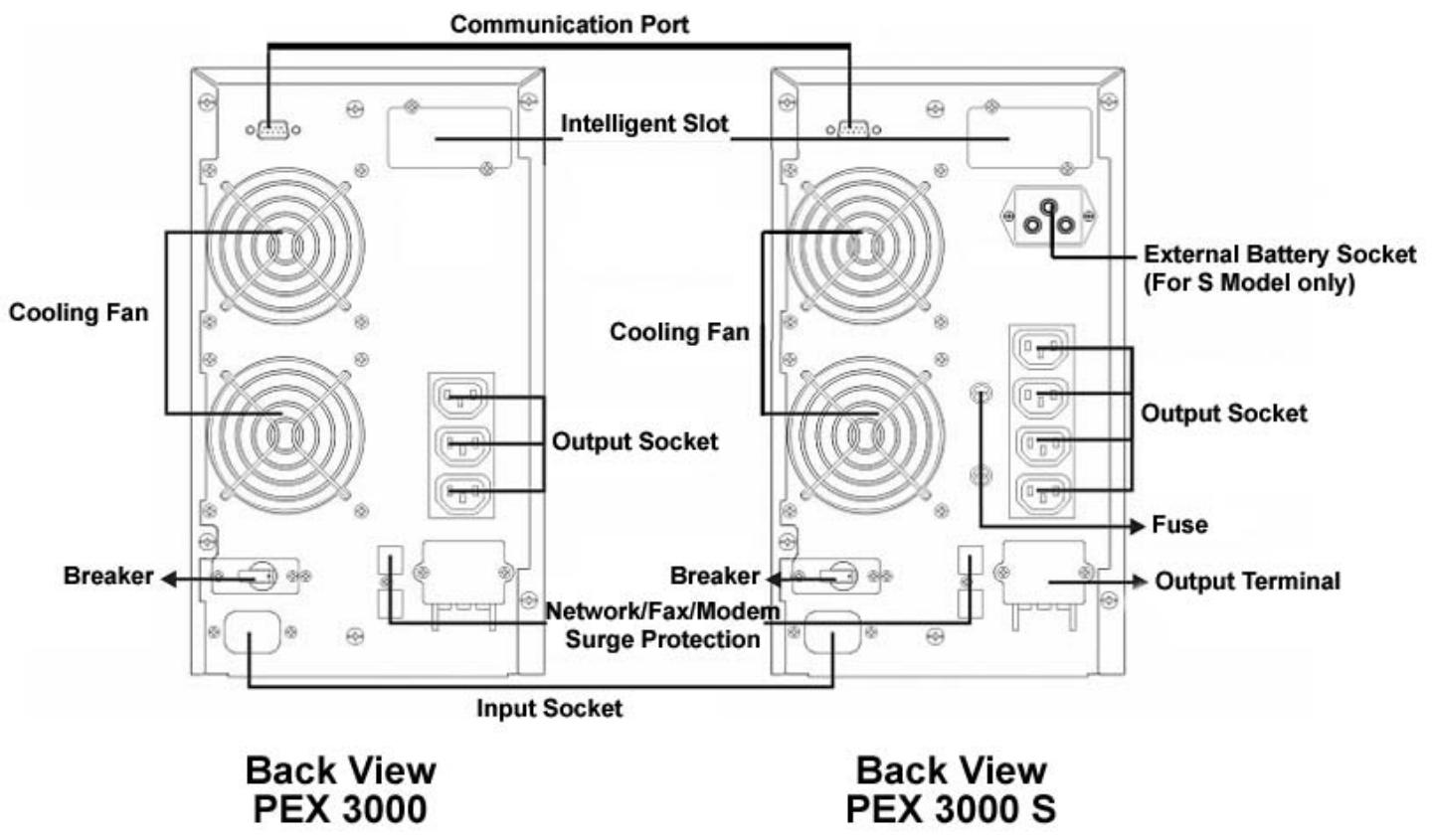
5.2.2 UPS Output Connection
The output of E^4 1000(S) and 2000(S) are IEC female type outlets (4 and 6). Plug the load power cord to the output outlets to complete connection.
| Model No. | Output Outlets | Terminal Block |
| 700 | 4 | Nil |
| 1000/1000S | 4 | Nil |
| 2000 | 6 | Nil |
| 2000S | 4 | Yes |
| 3000/3000S | 4 | Yes |
Besides output outlets, E^4 2000S and E^4 3000/3000S are equipped with a terminal block available for output as well.
The wiring configuration is shown as the following procedure:
- Remove the small cover of the terminal block
- Use AWG14 or 2.5mm2 wires for wiring configuration
- Connect cables to the terminal block and make sure to respect Line and Neutral positions.
- Put the rear panel protection cover back.
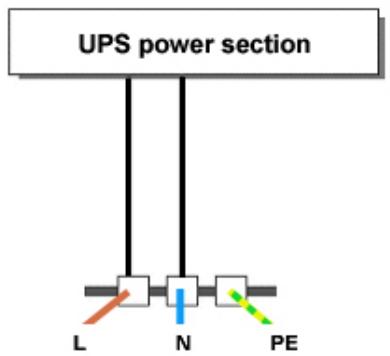
Schema 1: E ^4 2000S/3000/3000S connection diagram
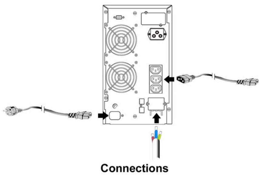
5.3 Computer Connection
Connect your computer to the outlet of the UPS system following the above diagram.
CAUTION - Do not connect equipment which would overload the UPS system (e.g. laser printers).
5.4 Battery Charge
To fully charge the batteries of the UPS system leave the UPS system connected to the mains for 8 hours. You may use the UPS system directly without charging batteries but the stored energy time may be shorter than the nominal value.
5.5 Turn On the UPS
5.5.1 With utility power connecting
For E^4 700/1000(S)/2000 UPS, press the "I" button for more than 1 second to turn on the UPS. For E^4 2000S, 3000 and 3000S UPS, set the Breaker on the rear panel to the "ON" position and press the "I" button for more than 1 second to turn on the UPS. The UPS starts a self-test. Then the UPS switches into the inverter mode and the "ON LINE" led, "INVERTER" led, "LOAD & BATTERY CAPACITY" leads light up.
5.5.2 Without utility power connecting
Even though utility power is connected to the UPS, the UPS still can be turned on by pressing the "I" button for more than 1 second. The UPS starts a self-test. Then the UPS switches into the inverter mode and the "BAT." led, "INVERTER" led, "LOAD & BATTERY CAPACITY" leads light up.
Note: In BY-PASS mode outlets are live when utility power and breaker are on. This can be configured by monitoring software.
5.6 Test Function
You may test the correct operation of the UPS system by either pressing the On-Switch "I" or disconnecting the input of the UPS system from the power supply.
5.7 Turn Off the UPS
5.7.1 In Inverter Mode
Press "按钮" button for more than 1 second to turn off the UPS. The UPS starts a self-test. Then the UPS switches into bypass mode and the UTILITY POWER led and BY-PASS led light up. At this time, the UPS outlets might be live. Disconnect the utility power or set the Breaker (for E^4 2000(S), E^4 3000 and 3000(S)) to "OFF" position to turn off the output.
5.7.2 In Battery Mode
Press "U" button for more than 1 second to turn off the UPS. Then the UPS starts a self-test. Then the UPS will be turned off completely.
5.7.3 Audible Alarm Mute Function
If the alarm is too annoying in battery mode, you may press "I" button for more than 1 second to stop it. When the battery is low, the alarm will be enabled to remind you to shutdown the load soon.
5.8 Operation procedure of external battery for long backup time Model (S)
5.8.1 External battery packs
a. Use the battery pack : 36VDC for E ^4 1000(S) (3 pcs of 12V batteries), 96VDC for E ^4 2000(S)/ 3000(S) (8 pcs of 12V batteries). Connection of lower or upper voltage batteries may cause damages.
b. One end of the external battery cord has to be connected to the UPS and the other end has to be connected to the battery pack.
5.8.2 Operation Procedure of External battery packs
Do not connect the UPS to any load yet. Connect the utility power cord to the UPS so it switches to UTILITY POWER mode.
On rear panel connect the plug of the external battery cord to the external battery outlet to complete the connection procedure and the UPS will start charging the battery pack (do not connect first on UPS because of short-circuit risks).
If the UPS system does not operate correctly, please attempt to solve the problem using the chart below.
| Problem | Possible cause | Remedy |
| No indication, no audible alarm even though system is connected to mains power supply. | No input voltage. | Check building wiring outlet and input cable. |
| “ON LINE” led blinks. | Line and neutral conductors have been reversed at the input of UPS system. | Rotate mains power outlet by 180° or connect UPS system. |
| “ON LINE” led blinks and “BAT.” led lights up. | Input power and/or frequency are out of tolerance. | Check input power source and inform dealer if necessary. |
| “ON LINE” and “BY-PASS” led light up even though the power supply is available. | Inverter not switched on. | Press On-Switch “1”. |
| “INVERTER” led lights up and an audible alarm beeps every 4 seconds. | Mains power supply has failed. | UPS automatically switches to battery mode. The audible alarm beeps every second to indicate that battery is almost empty. |
| “FAULT” led lights and an audible alarm beeps every second. | Overload. | Remove loads of UPS output. |
| “FAULT” led lights up and the alarm is continuously beeping. | UPS fault. | Notify dealer. |
| Emergency supply period shorter than nominal value. | Batteries not fully charged / batteries defect. | Charge the batteries for at least 8 hours and then check capacity. If the problem still persists, consult your dealer. |
| “FAULT” led lights, “BAT.” led blinks and an audible alarm beeps every second. | Charger or Batteries damaged. | Notify dealer. |
Please have the following information ready when calling the After-Sales Service
Department:
Model number, serial number.
Date of purchase and date on which the problem occurred.
Detailed description of the problem.

7.1 Operation
The UPS system contains no user-serviceable parts. If the battery service life (3 - 5 years at 25^ ambient temperature) has been exceeded, batteries have to be replaced. In this case please contact the after-sales service.
7.2 Storage
If the batteries are stored in temperate climatic zones, they should be charged every three months for 1 to 2 hours. In case of high temperatures, batteries should be charged once every two months.
8.1 Electrical specifications
INPUT
| Model No. | E4 700 | E4 1000(S) | E4 2000 | E4 2000S | E4 3000(S) |
| Phase | Single | ||||
| Frequency | (46~54)Hz | ||||
| Current(A) | 5A | 7A | 9A | 12A | 16A |
OUTPUT
| Model No. | E4 700 | E4 1000(S) | E4 2000(S) | E4 3000(S) |
| Power rating | 0,7kVA/0,5kW | 1kVA/0.7kW | 2kVA/1.4kW | 3kVA/2.1kW |
| Voltage | 220/230/240 × (±2%)VAC | |||
| Frequency | 50 × (±0.2%) Hz (Battery mode) | |||
| Wave form | sinusoidal | |||
BATTERIES
| Model No. | E4 700 | E4 1000 | E4 2000 | E4 3000 |
| Number and type | 3×12V 7.2Ah | 8×12V 7.2Ah | ||
Long backup time UPS (S) do not have any internal battery.
8.2 Operating Environment
| Ambient Temperature | 0 °C to 40 °C |
| Operating humidity | < 95% |
| Altitude | < 1000m |
| Storage temperature | 0 °C ~ 40 °C |
8.3 Typical stored energy time:
Typical values at 25^ in minutes:
| Model No. | 100 % Load | 50 % Load |
| E4700 | 9 | 21 |
| E41000 | 5 | 14 |
| E42000 | 9 | 21 |
| E43000 | 5 | 15 |
8.4 Dimensions and weights
| Model No. | Dimensions W x D x H (mm) | Net Weight kg |
| E4700 | 145X400X220 | 14 |
| E41000 | 145X400X220 | 14 |
| E41000 S | 145X400X220 | 7 |
| E42000 | 192X460X340 | 34.5 |
| E42000 S | 192X460X340 | 15 |
| E43000 | 192X460X340 | 35.5 |
| E43000 S | 192X460X340 | 16 |
Only units with CE markings comply with the following standards:
For E^4 700 / E^4 1000(S) / E^4 2000(S) / E^4 3000(S)
EN62040-1-1 (safety)
Conducted Emission: EN50091-2 Class B
Radiated Emission: EN50091-2 . Class B
Harmonic Current: EN61000-3-2
Voltage Fluctuations and Flicker: EN61000-3-3
EMS: EN61000-4-2(ESD) Level 4
EN61000-4-3(RS) Level 3
EN61000-4-4(EFT) Level 4
EN61000-4-5 (lighting surge protection) Level 4
EN61000-2-2 (Immunity to low frequency signals)
9.1 General specifications
| Model | E45000 | E45000S | E46000 | E46000S | E410000 | E410000S | |
| Power rating | 5KVA/3,5KW | 6KVA/4.2KW | 10KVA/7KW | ||||
| Frequency (Hz) | 50 | ||||||
| Input | Voltage | (176-276)VAC | |||||
| Current | 25A max | 31A max | 50A max | ||||
| Battery | Voltage | 240VDC | |||||
| Current | 20A max | 24A max | 40A max | ||||
| Output | Voltage | 220VAC | |||||
| Current | 23A | 27A | 45A | ||||
| Dimension (WxDxH) mm | 260x570x717 | ||||||
| Weight (kg) | 90 | 35 | 90 | 35 | 93 | 38 | |
9.2 Electrical Performance
| Input | ||
| Tension | Frequency | Power factor |
| Single-phase | 46Hz-54Hz | >0.98 (full load) |
| Output | |||||
| Voltage Regulation | Power Factor | Frequency tolerance | Distorsion | Overload capacity | Current crest ratio |
| ±1% | 0.7 lag | Synchronized 46-54Hz in Line mode (AC mode) ±0.1% of normal frequency in BATTERY mode | THD<2% Full load (Linear Load) | 105%-130% load transfers to bypass mode after 10 minutes >130% load transfers to BY-PASS mode after 1 second and shutdown the output after 1 minute | 3:1 maximum |
9.3 Operating Environment
| Temperature | Humidity | Altitude | Storage temperature |
| 0°C-40°C | <95% | <1000m | 0°C-40° |
Note: if the UPS is installed or used in a place where the altitude is above than 1000m , the output power must be reduced in use, please refer to the following:
| Altitude (M) | 1000 | 1500 | 2000 | 2500 | 3000 | 3500 | 4000 | 4500 | 5000 |
| Decrease in power | 100% | 95% | 91% | 86% | 82% | 78% | 74% | 70% | 67% |
10.1 Unpacking and control
- Unpack the packaging and check its contents. The shipping package should contain:
。 A UPS
A user guide
A communication cable + communication software
A battery cable for E ^4 5000S/ 6000S/ 10000S only
- Check that your UPS has not been damaged during transportation. In case of damage or if some part is missing, do not turn on the unit and notify immediately to the carrier and to your dealer.
10.2 Wiring
10.2.1 Notes for installation
- The UPS must be installed in a location with good ventilation, far away from water, inflammable gas and corrosive agents.
- Make sure the air vents on the front and back of the UPS are not blocked. Allow at least 50~cm of space on each side.
- Condensation to water drops may occur if the UPS is unpacked in a very low temperature environment. In this case before proceeding to installation and use and in order to avoid electric shock or short-circuit hazards it is necessary to wait until the UPS is fully dried inside out.
10.2.2 Installation
Installation and wiring must be performed in accordance with the local electric code and the following instructions by a qualified technician.
For safety, please cut off the mains power switch before installation. The battery breaker also needs to be cut off if it is a long backup time model ("S" model).
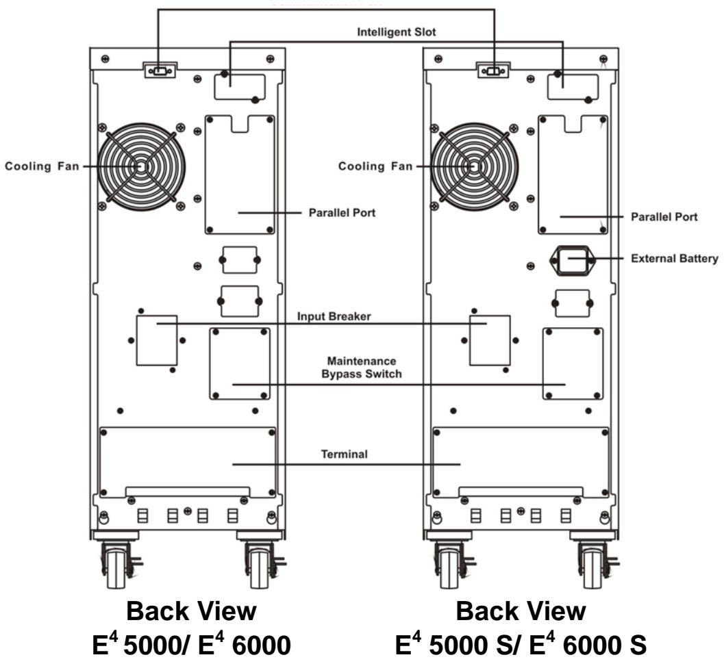
- Open the terminal block cover located on the rear panel of the UPS (please refer to schema 2 - p.20).
- For E^4 5000(S) and E^4 6000(S) UPS, it is recommended to select the UL1015 10AWG ( 6mm^2 ) wire or other insulated wire which complies with AWG Standard for the UPS input and output wirings.
- For E^4 10000(S), it is recommended to select the UL1015 8AWG (10mm²) wire or other insulated wire which complies with AWG Standard for the UPS input and output wirings.
Note: Do not use the wall receptacle as the input power source for the UPS, as its rated current is less than the UPS's maximum input current. The receptacle may be burned and destroyed.
| Model | Circuit breaker * | Input / Output Cable section |
| E4 5000 | 2 x 32 A | 3 x 6 mm² |
| E4 6000 | 2 x 40 A | 3 x 6 mm² |
| E4 10000 | 2 x 63 A | 3 x 10 mm² |
*In case of Earth Leakage Circuit Breaker, min 300mA selective.
WARNING: If the connecting of neutral wire (N) and Line wire (L) is in order, the UPS do not change neutral rate of installation. A circuit breaker connected before the UPS will operate for an insulation fault after the UPS.
Sensibility of the circuit breaker takes into account the UPS current leak (about 15mA) and connected computers. We recommend selective 300mA.
- Connect the input and output wires to dedicated input and output terminals according to the following diagram.
Note: make sure that the input and output wires and the input and output terminals are connected tightly.
- The wire diameter of protective earth wire should be at least as mentioned above. And green wire or green wire with yellow ribbon wire has to be used.
- After the installation completed, make sure the wiring is correct.
- If necessary please install the leak current protective breaker at the output power distribution panel of the UPS.
- To connect the load to the UPS, please turn off all connected devices first, then perform the connection and finally turn on the loads one by one.
- Connected or not to the utility power, the output of the UPS may have electricity. The parts inside the unit may still have hazardous voltage after turning off the UPS. To make sure that the UPS is no more live, turn off the UPS and then disconnect the utility power supply.
- Before use it is recommended to charge batteries for 8 hours. After connection, turn the bypass breaker into "ON" position, the UPS will automatically charge the batteries. You can also immediately use the UPS without charging the batteries first but backup time may be shorter than the nominal value.
- If you have to connect to the UPS an inductive load such as a monitor or a laser printer (not advisable), please make sure that the UPS capacity is at least twice as much as the power of the connected equipment otherwise its start-up power consumption might be too high.
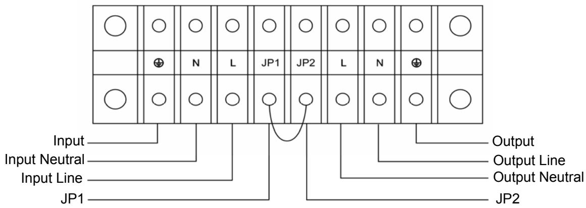
Schema 2: Input and output Terminal Block wiring diagram of E^4 5000(S)/6000(S)/10000(S)
Important notes: If the UPS is used in single mode, JPI and JP2 must be connected by 10AWG (6mm2). If the UPS is used in parallel mode, the Jumper between JP1 and JP2 must be removed.
10.3 Operating procedure for connecting the long backup time model UPS with the external battery
- The nominal DC voltage of external battery pack is 240VDC. Each battery pack consists of 20 pieces of 12V maintenance free batteries in series. To achieve longer backup time, it is possible to connect multi-battery packs and it is strongly recommended to use same type of batteries.
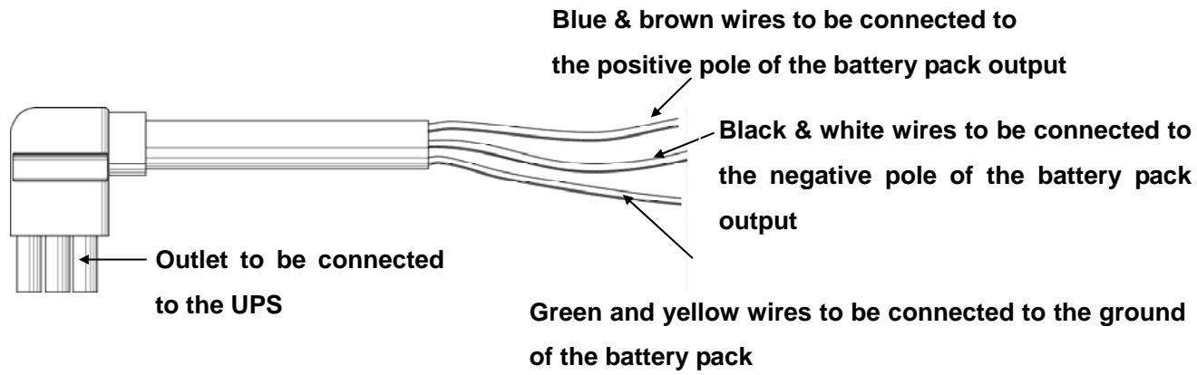
- The connector of the external battery cable is used to plug into the external battery outlet of the UPS; the other end of the external battery cable is made of three open wires to connect to the external battery pack(s). The installation procedure should be strictly followed to avoid hazards of electric shocks.
a) A DC breaker must be connected between the battery pack and the UPS. The capacity of this breaker should not be lower than the data specified in the general specifications.
b) Set the battery pack breaker in "OFF" position and connect the 20 pieces of batteries in series.
c) Connect the external battery cable to the battery first (do not connect the cable to the UPS first, you may encounter hazards of electric shock). The positive pole of the battery is connected to the E^4 10000S in parallel with blue and brown wires; the negative pole of the battery is connected to the E^4 10000S in parallel with black and white wires; the green and yellow ribbon wire is connected to the ground of the battery cabinet.
- To complete the connection plug the connector of the external battery cable into the external battery outlet at the back of the UPS. Then switch the breaker of the battery pack to "ON" position. Then switch the bypass breaker to "ON" position. The UPS begins to charge the battery packs.
10.4 Parallel operation
10.4.1 Brief introduction of the redundancy
N+X is currently the most reliable power supply structure. N represents the minimum UPS number that the total load needs; X represents the redundant UPS number, i.e. by default the UPS number that the system can handle simultaneously. The bigger the X is the higher the reliability of the power system will be. When reliability is essential, N+X is the optimal mode.
As long as the UPS is equipped with parallel cables, up to 3 UPS can be connected in parallel to realize output power sharing and power redundancy.
10.4.2 Parallel installation
- Users need to opt for a standard 25-pin communication cable, which should have 25 cores, corresponding stitches and shield, as the UPS parallel cable. The length of the parallel should not be less than 3m .
- Strictly follow the stand-alone wiring requirement to perform the input wiring of each UPS.
- Connect the output wires of each UPS to an output breaker panel.
- Disconnect first the Jumper between JP1 and JP2 then connect each input breaker to a main input breaker and each output breaker to a main output breaker and then to the loads.
10.4.3 Requirement for output wiring
- When the distance between the UPS in parallel and the breaker panel is less than 20 meters, the difference between the wires of input & output of the UPS is required to be less than 20% .
- When the distance between the UPS in parallel and the breaker panel is greater than 20 meters, the difference between the wires of input & output of the UPS is required to be less than 10% .
11.1 Operation and maintenance
- To perform the general operation, please refer to instructions here below.
- Note: the units switch to "INVERTER" mode simultaneously as they start up one by one in utility power mode.
SHUTDOWN: turn off all units ones by one (slightly press OFF). When the last unit turns off, each UPS simultaneously shuts down the INVERTER MODE and starts working in BYPASS MODE.
It is easy to operate the equipment with no previous training. You just need to read through this manual and carefully follow all instructions. For the meaning of the LED Indicators, please refer to the appendix 2: "Display panel".
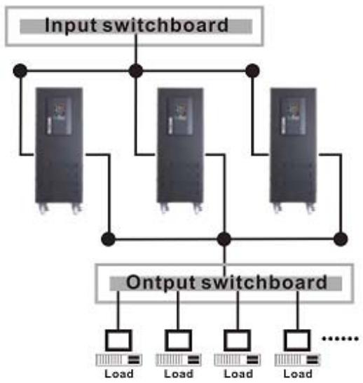
Parallel Installation Diagram
11.2 Operation
11.2.1 Turn on the UPS with utility power supplied (in Line mode/AC mode)
- Check power supply connection and switch the input breaker on back of UPS to "ON" position. The "ON LINE" led lights on. Ventilation system starts and the UPS supplies power to the load via the bypass ("BY PASS" led lights on).
- To turn on the UPS press the green "ON" button for more than 1 second.
- The "LOAD/BATTERY LEVEL" leads light on one by one. After a few seconds the "INVERTER" led lights on, the "BY-PASS" led lights off and henceforth the UPS is running in Utility Power mode. If the utility power is faulty, the UPS automatically switch to battery mode avoiding any interruption.
11.2.2 Turn on the UPS with no utility power supplied (in Battery mode)
- Press the red "ON" button for more than 1 second to power on the UPS.
- For long backup time model ("S" model), please make sure that the battery breaker is in "ON" position.
-
Starting up process in battery mode is identical to starting up process in AC mode. Only is the "BAT." led lighted on instead of the "ON LINE" led.
-
Press the green "OFF" button for more than 1 second to turn off the inverter of the UPS.
- The "LOAD/BATTERY LEVEL" leads light on one by one, then the "INVERTER" led lights off and "BY-PASS" led lights on. The UPS is now in BY-PASS mode.
- Output terminals of UPS are still live. To turn off the output terminals, simply cut off the utility power supply.
11.2.4 Turn off the UPS with no utility power supplied (in Battery mode)
- Press the "OFF" button for more than 1 second to turn off the UPS.
- The "LOAD/BATTERY LEVEL" leads light on one by one. Then all leds light off. There is now no more voltage available from the UPS output.
Note: Please turn off the connected loads before turning on the UPS. Turn on the loads one by one after the UPS started working in INVERTER mode. Turn off all of the connected loads before turning off the UPS.
11.2.5 Parallel Machine Maintenance
This UPS system has parallel machine function. To add a UPS to a parallel system, please refer to 11.2.6: "Wire an additional UPS". To remove a UPS, please refer to 11.3: "Operational process of removing single UPS" and follow operational processes of removing parallel machine.
11.2.6 Wire an additional UPS
- Before connecting an additional UPS, user should prepare input and output line, switch and combine line.
- Input and output breakers on the Power Panel should be turned off. Connect the input and output wires to dedicated input and output terminals (Chapter 10.2.2: "Installation").
- Switch all UPS to "STATIC BY-PASS" mode by pressing "OFF". When the last UPS is turned off, make sure they all switched to "BY-PASS" mode. Then remove the metal maintenance plates from the "Maintenance By-Pass Switch" and turn the switch from "UPS" to "BPS". Turn off the input breakers on the rear panel of each UPS. All existing UPS now switched to MANUAL BY-PASS mode.
- WARNING: If you have a single UPS system, make sure to remove the connection between JP1 and JP2. In a parallel system, the connection between JP1 and JP2 has already been removed.
-
On back of one of the existing UPS remove the metal plate from parallel port, connect the parallel cable to the connector and screw the metal plate back on. Then remove the metal plates from the "Maintenance By-Pass Switch" on back of the new UPS and turn the switch from "UPS" to "BPS".
-
Switch on the battery breaker of the new UPS (S model) and the input breaker on the "Power Panel". Measure the difference between the line (L) connector of new UPS and the Line (L) connector of Parallel System. If the difference is < 1V , the user may switch on the output breaker of the new UPS. Now the complete system (including the new UPS) has turned to MANUAL BY-PASS mode.
- On back of the new UPS remove the metal plate from parallel port and connect the parallel cable to the dedicated connector. Then screw the metal plate back on.
- On back of each UPS (including the new UPS) switch the input breakers to "ON" position. When all UPS are in "BY-PASS" mode turn them on one by one by pressing "ON" (front face). Make sure there is no fault and that all UPS switch simultaneously to "INVERTER" mode. Also check the voltage between JP1 and JP2 of each UPS: it should be < 1 VAC.
- Please check the voltage difference between all JP2 on the UPS terminal blocks: it should be less than 5V . The average voltage rate is 2V .
- Turn off all UPS one by one by pressing "OFF". Make sure there is no fault and that all UPS switch simultaneously to "BY-PASS" mode. Remove the metal plates from the "Maintenance By-Pass Switch" and turn the switch from "BPS" to "UPS". Then screw the metal plate back on.
- Turn on all UPS one by one by pressing "ON" and make sure all UPS switch simultaneously to "INVERTER" mode. Now is the system working in parallel.
Note: If there is any fault in step 8 and 9, please follow operational process of removing single UPS to maintain.
11.3 Operational process of removing single UPS
- To disconnect a UPS please press the "OFF" button twice, the UPS output will be turned off.
- Turn off the input breaker of the UPS to be removed, the battery breaker (for S Model) and turn off the input breaker on the "Power Panel".
- Switch off the other UPS one by one by pressing "OFF", make sure there is no fault and that all UPS switch simultaneously to BY-PASS mode. Remove the metal plates from the "Maintenance By-Pass Switch" and turn the switch from "UPS" to "BPS". Screw the metal plate back on. Then turn off all UPS input breakers. Now all UPS are in "MANUAL BY-PASS" mode
- Disconnect the UPS to be removed. If the remaining UPS is running in single mode, you must connect JP1 and JP2 of the output terminal.
- Remove metal plates from parallel port and disconnect the parallel cable from the other UPS. Then screw the metal plate back on.
- Turn on the input breakers of remaining UPS and wait for them to switch to "BY-PASS" mode. Remove the metal plates from the "Maintenance By-Pass Switch" and turn the switch from "BPS" to "UPS". Then screw the metal plate back on. Turn on all UPS one by one by pressing "ON" and make sure there is no fault and that all UPS switch simultaneously to "INVERTER" mode. Now is the system working in parallel.
- Please connect JP1 and JP2 of the terminal block for the UPS which has been disconnected.
11.4 Combine machine warning
- When UPS system runs in INVERTER mode, make sure that "Maintenance By-Pass Switches" are all in "UPS" position or all in "BPS" position.
-
When UPS work in parallel mode, please do not operate the "MANUAL BY-PASS" Switch.
-
When E^4 UPS works properly, there is no need for battery maintenance. Batteries used for standard models are value regulated sealed lead-acid maintenance free battery. These models require minimal repairs. The only requirement is to regularly charge the UPS in order to maximize the expected life of the battery. When being connected to the utility power, whether the UPS is turned on or not, the UPS keeps on charging the batteries which are protected against overvoltages and serious discharging.
- When the UPS is not being used nor has been used for a long period of time, it is recommended to charge the battery of the UPS once every 4 to 6 months.
In tropical regions, the battery should be charged and discharged every 2 months. The standard charging time should be at least 12 hours. - Under normal conditions, at room temperature 20^ , battery life goes from 3 to 5 years. If the battery is flat, it has to be replaced and replacement should be performed by qualified personnel.
- Batteries have to be replaced with the same number and same type of batteries.
- Do not replace the battery individually. All the batteries should be replaced at the same time following the instructions of the battery supplier.
- Batteries should be discharged once every 3 months. To do so switch the UPS to battery mode for 8 hours.
1) When working on batteries the following precautions should be observed: remove conductive jewelry such as necklace, wrist watches and rings.
2) If any connection cable has to be replaced, please purchase the original materials from the authorized distributors or service centers in order to avoid any risk of overheating or fire due to insufficient capacity.
3) Do not dispose of the battery in a fire as it may explode.
4) Do not open or mutilate the battery. Released electrolyte is harmful to the skin and eyes. It may be toxic.
5) Do not short-circuit the positive and negative of the battery electrode, connection errors could cause electric arcs resulting in serious burns.
6) ! !WARNING: Make sure that there is no voltage before touching the batteries. The battery circuit is not isolated from the input potential circuit. There may be hazardous voltage between the battery terminals and the ground.
7) Even though the input breaker is disconnected, the components inside the UPS are still live and there are potential hazardous voltages. Therefore, before any maintenance and repairs work is carried out, switch off the breaker of the battery pack (for S model) or disconnect the jumper wire of connecting between the batteries.
8) Servicing of batteries should be performed or supervised by personnel knowledgeable of batteries and the required precautions. Keep unauthorized personnel away from batteries.
9) For any kind of work to be operated on batteries, it is imperative to switch the UPS to MANUEL BY-PASS mode.
| Problem | Possible cause | Solution |
| The n°1“FAULT” led and the n°6 led switch on, the alarm beeps continuously. | Shutdown of UPS due to internal overheats. | Make sure that the UPS is not overloaded, the air vents are not blocked and the ambient temperature is not too high. Wait for 10 minutes for the UPS to cool down before turning on again. If failed, please contact the distributor or service center. |
| The n°1“FAULT” led and the n°2 and n°5 leads switch on, and the alarm beeps continuously. | The UPS output is short-circuited. | Turn off the UPS. Remove all the connected loads. Ensure that connected equipment and UPS have no internal faults before turning it on again. If failed, please contact the distributor or service center. |
| The n°1“FAULT” led and the n°4 led switch on, the UPS beeps continuously. | Shutdown of UPS due to an internal fault. | Please contact the distributor or service center. |
| The n°1“FAULT” led and the n°5 led switch on, the UPS beeps continuously. | Shutdown of UPS due to an internal fault. | Please contact the distributor or service center. |
| The n°1“FAULT” led and the n°3 led switch on, the UPS beeps continuously. | Overcharging protection. | The charger of the UPS is faulty. Please contact the distributor or service center. |
| The “ON LINE” led flashes. | The voltage or frequency of the utility power is out of the input range of the UPS. | The UPS is running in battery mode. Save your data and close the application program. Make sure the utility power is within the input voltage or frequency range allowed by the UPS. |
| The n°1“FAULT” led and the n°2 led switch on, the UPS beeps continuously. | The UPS is overloaded or the load equipment is faulty. | Check connected loads and remove all no-critical equipment. Recalculate the load power and reduce the number of loads connected to the UPS. Check that connected loads are not faulty. |
| The n°1“FAULT” led and the “BAT.” led switch on, the alarm beeps every second. | The charger of the UPS is faulty. | Please contact the distributor or service center. |
| “BAT.” led flashes | Battery low or battery not connected. | Check the battery. If the battery is faulty, replace the battery immediately and make sure that the battery breaker is in “ON” position. |
| The utility power is normal, but the UPS do not work in line mode | By-pass breaker in “OFF” position. | Set the by-pass breaker on “ON” position. |
| In battery mode backup time is lower than nominal value | Battery not fully charged. | Keep UPS connected to utility power for at least 10 hours to recharge the batteries again. |
| UPS overloaded. | Check the loads and remove the non-critical equipment. | |
| Battery is faulty or too old. | Replace the batteries. Please contact the distributor to obtain the parts and replacement service. | |
| The UPS cannot power on after pressing the “ON” button | The “ON” button has been pressed too briefly. | Press the “ON” button for more than 1 second. |
| The UPS is not connected to the battery or the battery pack voltage is too low. | Check the battery or recharge the battery. | |
| UPS fault. | Please contact the distributor or service center. |
When you contact the service center, please provide the following informations:
Model No. and the serial No. of the UPS.
The date when the problem arose.
Complete description of the problem, including the LED display, alarm warning, power condition and load capacity.
□ If your UPS is a long backup time model (“S” version), you may also need to provide the service center with battery information.

15.1 ON LINE MODE
The "ON LINE" led and the "INVERTER" led switch on. The "LOAD LEVEL" leds (leds from 6 to 2) switch on in accordance with the load capacity connected (See below Fig 15.1).
- If the "BAT." led switches on and the "ON LINE" led flashes, it indicates the voltage or frequency of the utility power has exceeded the normal range, the UPS operates in BATTERY mode.
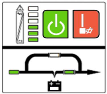
Fig 15.1: The utility power mode
- If the output is overloaded, the "LOAD LEVEL" leads switch on and the audible alarm beep twice every second. It is recommended to get rid of some non-critical loads one by one to decrease the loads connected to the UPS less than 90% of its nominal power capacity.
Note: Please follow the following steps to connect the generator :
- Activate the generator and wait until the operation is stable before supplying power of the generator to the UPS (make sure the UPS is in idle mode). Then turn on the UPS according to the start-up procedure. Once the UPS is on, you may connect the loads to the UPS one by one.
- The power capacity of the AC generator should be at least twice higher than the capacity of the UPS.
15.2 Battery mode
The "BAT." led and the "INVERTER" led are switched on. The "BATTERY LEVEL" leads switch on in accordance with the load capacity connected (See below Fig 15.1).

Fig 15.2: Battery mode
Note: In UTILITY POWER mode "LOAD LEVEL" leds will indicate the number of connected loads. In BATTERY mode, the leds indicate the level of battery capacity.
- When the UPS is running in BATTERY mode, the alarm beeps once every 4 seconds. If you press the "ON" button on the front panel for more than 1 second again, the alarm will stop beeping (silence mode). Press the "ON" button once again for more than 1 second to resume the alarm function.
- When the battery capacity decreases, the number of the "BATTERY CAPACITY" leads turned on decreases. If the battery voltage keeps decreasing and reaches "LOW BATTERY" level, the alarm will beep once every second to remind the user the battery capacity is low and the UPS is soon going to shut down automatically. Then all operations and programs should be quickly saved and connected loads disconnected one by one.
15.3 Bypass mode
The "ON LINE" led and the "BY-PASS" led are lit up. "LOAD" leds (6 to 2) will light on in accordance with connected loads. The alarm will beep once every 2 minutes in BY-PASS mode (Fig 15.3).
The "ON LINE" led flashes: it shows the voltage or frequency of the utility power has exceeded the normal range of the UPS.
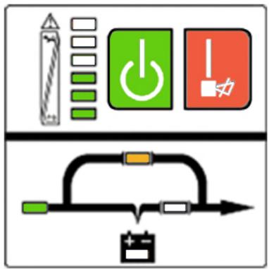
Fig 15.3: UPS bypass mode diagram
- Other indications on the display panel are the same as in UTILITY mode.
- In BY-PASS mode there is no backup time function. Connected equipments are directly mains-operated via an internal filter.
15.4 Fault mode
The FAULT led lights up while the UPS is running: please refer to chapter 14: "Trouble shooting".
16.1 RS232 Interface
Description of DB-9 connector.
| Pin # | Description | I/O |
| 2 | TXD | Output |
| 3 | RXD | Input |
| 5 | GND | Input |
16.2 AS400 Interface (Option)
The E^4 UPS may be equipped with an AS400 card (optional) for AS400 communication protocol. Please contact your local distributor for details. The following is the pin assignment and description of DB-9 connector in AS400 card.
| Pin # | Description | I/O |
| 1 | UPS Fail | Output |
| 2 | Summary Alarm | Output |
| 3 | GND | Input |
| 4 | Remote Shutdown | Input |
| 5 | Common | Input |
| 6 | Bypass | Output |
| 7 | Battery Low | Output |
| 8 | UPS on | Output |
| 9 | Line Loss | Output |
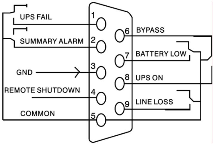
Fig 16.2: DB-9 Interface of AS400 Communication protocol
Note: It is also possible to insert a SNMP AGENT in the "Intelligent Slot".
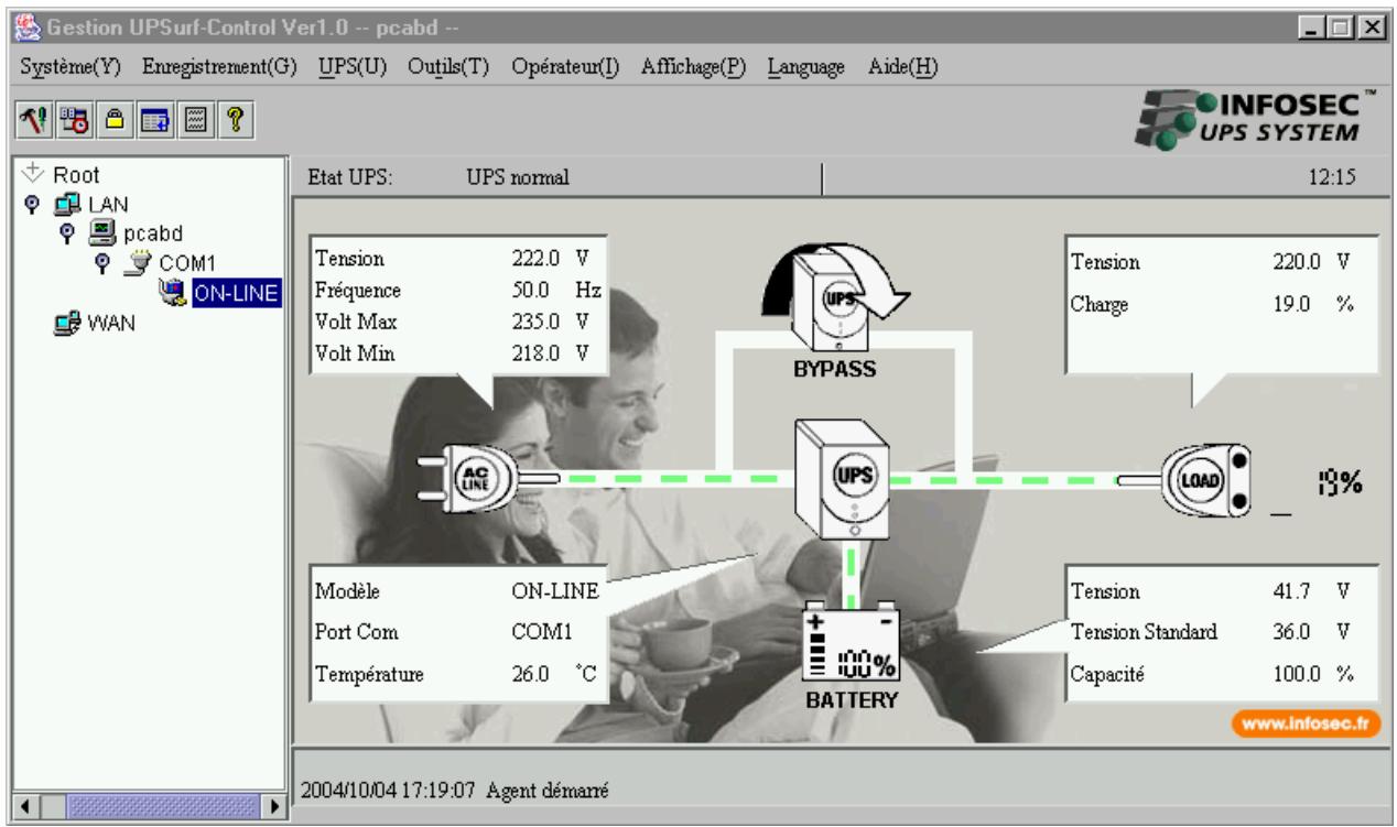
17.1 Free Software Download - UPSurf-Control
UPSurf-Control is a new UPS monitoring software which provides user-friendly interface to monitor and control your UPS. This unique software provides safely auto shutdown for multi-computer systems. With this software, users can monitor and control any UPS on the same LAN no matter how far from the UPS.
17.2 Installation procedure
If the CD-Rom is not provided with the UPS, please follow the instructions here below:
- Go to the website: http://www.infosec.fr
- When downloading all required files from the internet to install the software, enter the serial No: 511C1-01220-0100-478DF2A.
When your computer starts again, the UPSurf-Control software will appear as a green plug icon located in the system tray, near the clock.
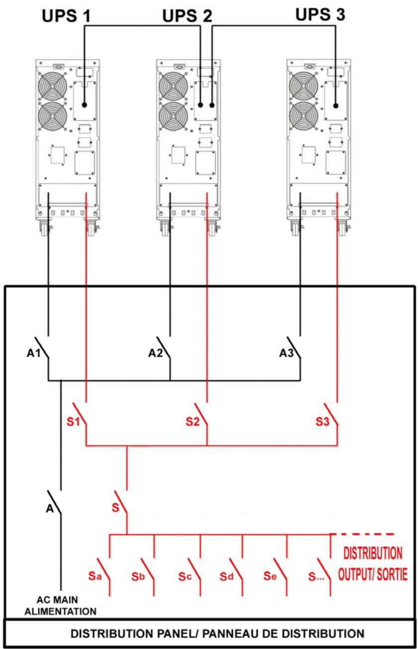
| Template Breaker | ||
| A/S | A1-A2-A3 / S1-S2-S3 | |
| E45000 | 2X80A | 2X32A |
| E46000 | 2X100A | 2X40A |
| E410000 | 2X175A | 2X63A |
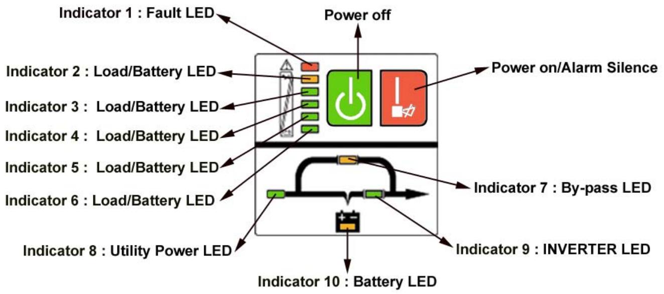
| N° | Operating state | LED display | Alarm warning | ||||||||||
| 1# | 2# | 3# | 4# | 5# | 6# | 7# | 8# | 9# | 10# | ||||
| 1 | Utility Power Mode | 0~35% Load capacity | • | • | • | none | |||||||
| 2 | 36%~55% Load capacity | • | • | • | • | none | |||||||
| 3 | 56%~75% Load capacity | • | • | • | • | • | none | ||||||
| 4 | 76%~95% Load capacity | • | • | • | • | • | • | none | |||||
| 5 | 96%~105% Load capacity | • | • | • | • | • | • | • | none | ||||
| 6 | Battery Mode | 0~20% Battery capacity | • | • | • | Beep once every sec | |||||||
| 7 | 21%~40% Battery capacity | • | • | • | • | Beep once every 4 sec | |||||||
| 8 | 41%~60% Battery capacity | • | • | • | • | • | Beep once every 4 sec | ||||||
| 9 | 61%~80% Battery capacity | • | • | • | • | • | • | Beep once every 4 sec | |||||
| 10 | 81%~100% Battery capacity | • | • | • | • | • | • | • | Beep once every 4 sec | ||||
| 11 | Bypass mode | ↑ | ↑ | ↑ | ↑ | • | • | • | Beep once every 2 min. | ||||
| 12 | overloaded in utility mode and UPS still in INV mode | • | • | • | • | • | • | • | • | Beep twice every sec. | |||
| 13 | overloaded in utility mode and UPS in bypass mode | • | • | • | • | Continuously beep | |||||||
| 14 | Utility power abnormal | ↑ | ↑ | ↑ | ↑ | • | ★ | ↑ | ↑ | ↑ | ↑ | ||
| 15 | Overloaded in battery mode, Early-warning | • | • | ↑ | ↑ | ↑ | ↑ | • | • | Beep twice every sec. | |||
| 16 | Overloaded in battery mode, Cut off the output | • | • | Continuously beep | |||||||||
| 17 | Over temperature | • | • | ↑ | ↑ | Continuously beep | |||||||
| 18 | Inv abnormal | • | • | ↑ | ↑ | Continuously beep | |||||||
| 19 | Output short circuited | • | • | • | ↑ | ↑ | Continuously beep | ||||||
| 20 | BUS voltage abnormal | • | • | ↑ | ↑ | Continuously beep | |||||||
| 21 | Charger or battery failed | • | • | • | ↑ | ↑ | ★ | Continuously beep | |||||
| 22 | Battery voltage abnormal | ↑ | ↑ | ↑ | ↑ | ↑ | • | • | ★ | ↑ | |||
| 23 | BAT SCR failed | • | • | • | Continuously beep | ||||||||
| 24 | Fan abnormal | • | • | • | • | • | Continuously beep | ||||||
| 25 | Bypass STS failed | • | • | • | • | • | Continuously beep | ||||||
| 26 | INV RLY failed | • | • | • | • | • | Continuously beep | ||||||
| 27 | Communication abnormal | • | • | • | ↑ | ↑ | Continuously beep | ||||||
Solid ON ★ : Flash ↑ : LED display and alarm warning are dependent on other conditions.
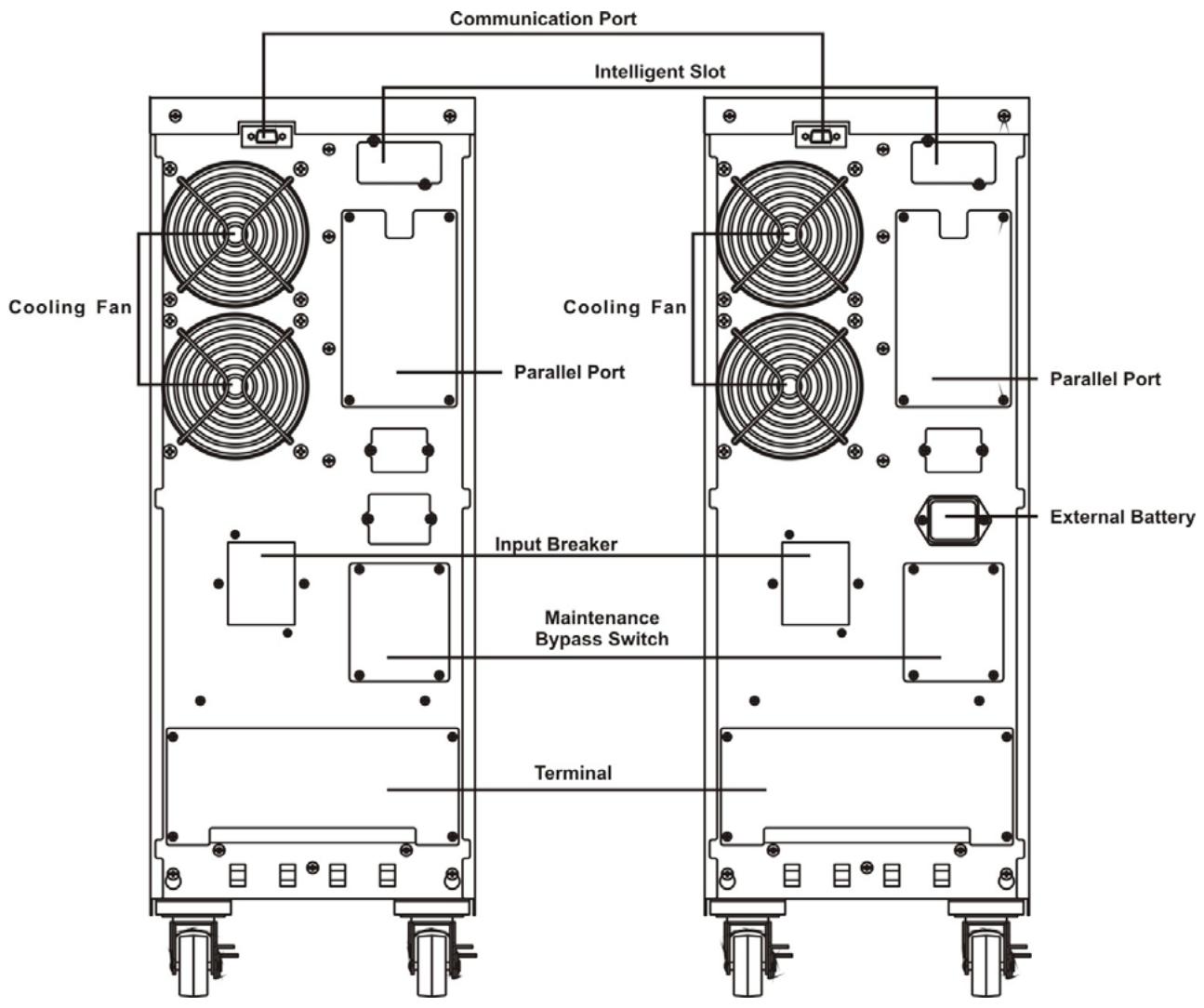
Back View E4 10000
Back View E4 10000 S