
FSE 400 - Off-road motorcycle GAS GAS - Free user manual and instructions
Find the device manual for free FSE 400 GAS GAS in PDF.

| Product Type | Off-road motorcycle (enduro) |
| Brand | GAS GAS |
| Model | FSE 400 |
| Displacement | 400 cc |
| Engine Type | 4-stroke single-cylinder |
| Cooling | Liquid |
| Transmission | 6-speed |
| Starting | Electric |
| Dry Weight | Approximately 115 kg |
| Seat Height | 950 mm |
| Fuel Tank Capacity | 8.5 liters |
| Engine Oil (with filter) | 1.2 liter |
| Exhaust Valve Clearance | 0.50 mm |
| Brakes | Front disc Ø 260 mm, rear Ø 220 mm |
| Front Suspension | Inverted fork Ø 48 mm |
| Rear Suspension | Adjustable mono-shock |
| Front/Rear Tires | 90/90-21 / 140/80-18 |
| Battery | 12 V – 6 Ah |
| Average Fuel Consumption | Approximately 4 L/100 km |
Frequently Asked Questions - FSE 400 GAS GAS
User questions about FSE 400 GAS GAS
0 question about this device. Answer the ones you know or ask your own.
Ask a new question about this device
Download the instructions for your Off-road motorcycle in PDF format for free! Find your manual FSE 400 - GAS GAS and take your electronic device back in hand. On this page are published all the documents necessary for the use of your device. FSE 400 by GAS GAS.
USER MANUAL FSE 400 GAS GAS
WORKSHOP MANUAL ENGINE FSE 450
2004 / 2005

CASCAS
Contents
Technical specifications. 4
Uninstalling and installing the engine in the chassis............5
Engine dismounting. 15
Engine mounting. 33
Replacement of the standard clutch with the ADLER
clutch APTC. 53
Inspection and maintenance
of the engine components 59
Periodic maintenance. 91
Technical Specifications
MODEL FSE 400/450
ENGINE
Displacement in cubic centimetres 399 cc / 443 cc
Type 4 stroke DOHC 4 valves
No. of Cylinders One
Cooling System Water Cooled
Bore and stroke 90 x 62,6 mm / 95 x 62,6 mm
Injection Fuel injection electronic system Magneti Marelli
Ignition Integrated in fuel injection electronic system
Clutch Oil bath, multi-disk hydraulic action
Gear Box 6 speed
CHASSIS
Frame Type DELTABOX, semi double cradle chassis made from rectangular Cromoly tubes. Aluminium swing arm
Front Suspension Inverted Marzocchi Diameter 45 mm Run 295 mm Inverted Ohlins Diameter 48 mm Run 295 mm
Rear Suspension Progressive system with Ohlins shock absorber Run 320 mm
Front brake
Disk of 260 mm
Nissin Pump and simple / double Nissin calliper
Rear brake
Disk of 220 mm
Nissin Pump and simple / double Nissin calliper
Wheels
Rims D.I.D. Type U with tyres Michelin Comp3
DIMENSIONS
Wheel base 1.475 mm
Seat Height 940 mm Minimum ground clearance 340 mm Fuel Tank Capacity 7.2 litres
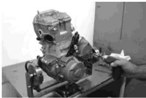
Un-installing and installing the engine in the chassis
Un-installing the engine in the chassis
Before dismounting the engine from the frame, wash it with a steam washer. The dismounting sequence is explained in the following steps.
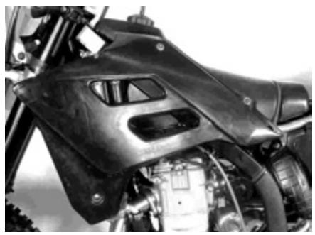
Dismount the seat and the frame covers.
Empty the engine oil.
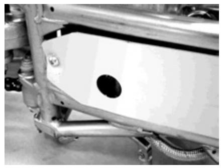
Remove the engine plate.
Empty the chassis (A) oil ta
Empty the coolant of the engine (B).
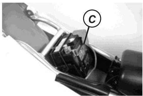
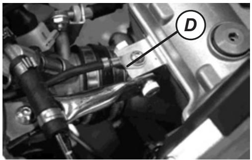
Disconnect the wire (-) of the battery (C) and the engine earth connection (D).
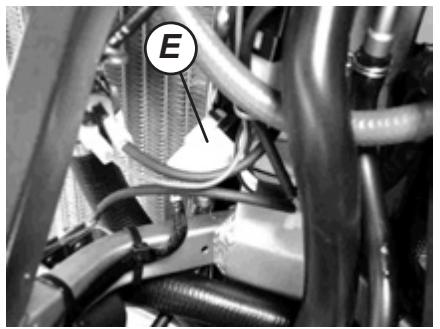
Disconnect the alternator clamp (E) and the phonic wheel sensor wire.
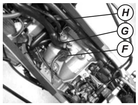
Disconnect the spark plug pipe (F), the engine oil vaporiser tube (G), the engine oil reservoir vent hose (H).
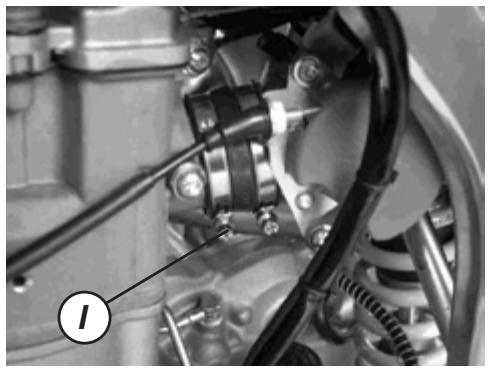
Loosen the cylinder head injector tubing clamp (I).
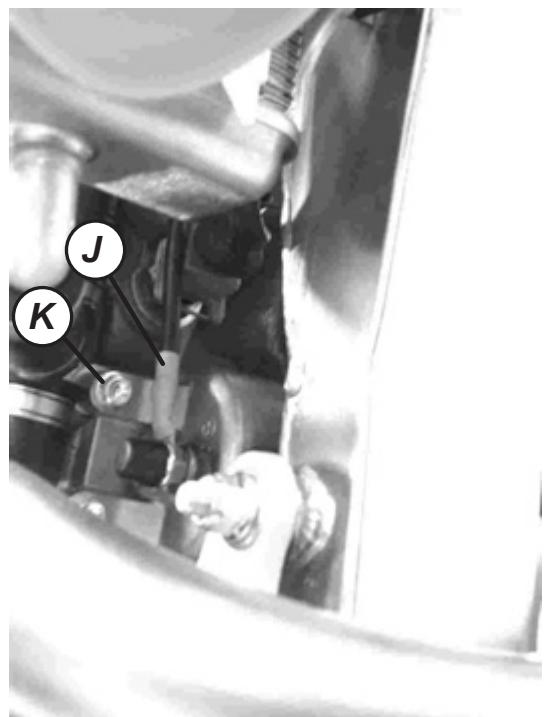
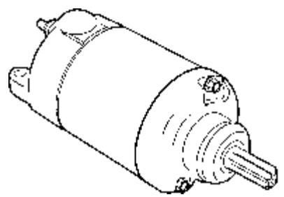
Disconnect the starter motor connection wire (J). Dismount the starter motor removing the screws (K).
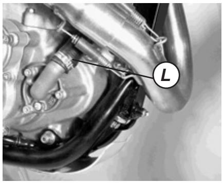
Dismount the water tube (L).
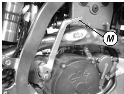
Remove the pedal starter lever (M).
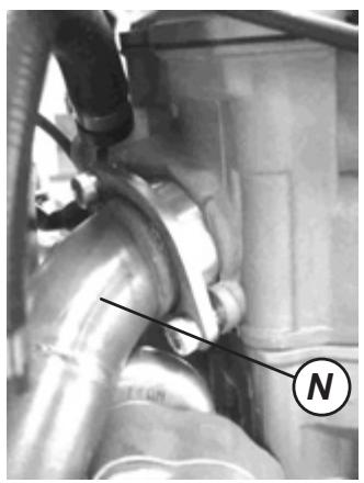
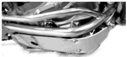
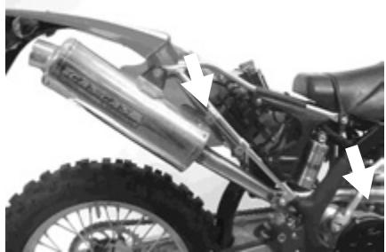
Remove the exhaust collector (N).
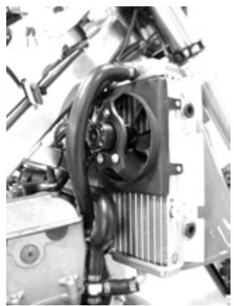
Disconnect the 2 radiator tubes.
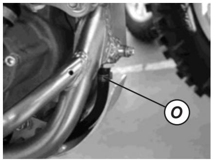
Disconnect the engine oil tube (O) in the chassis tank.
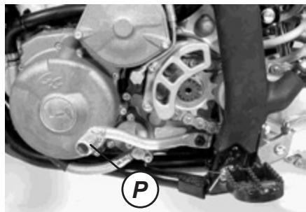
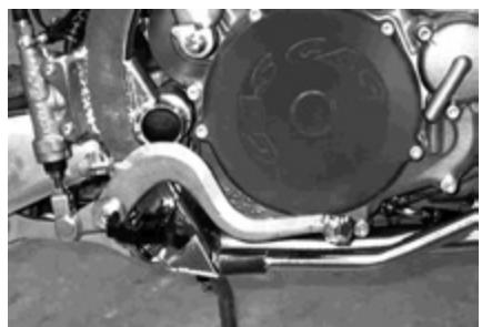
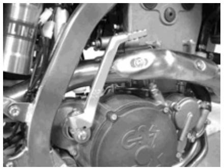
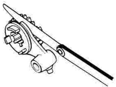
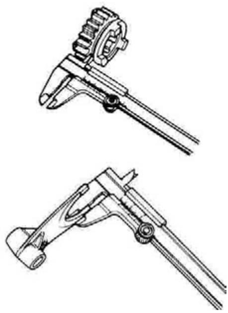
Remove the gearshift lever (P).
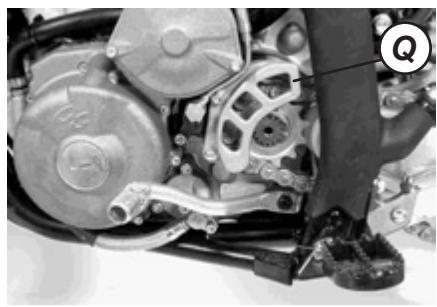
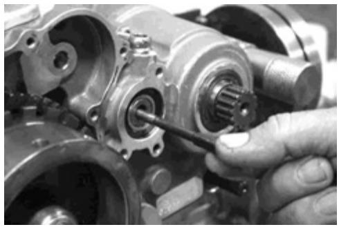
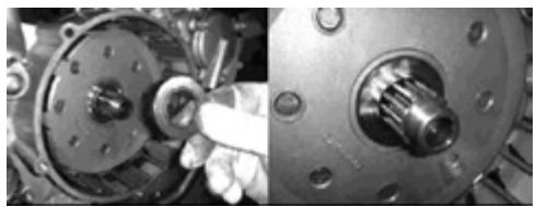
Remove the engine pinion protector (Q).
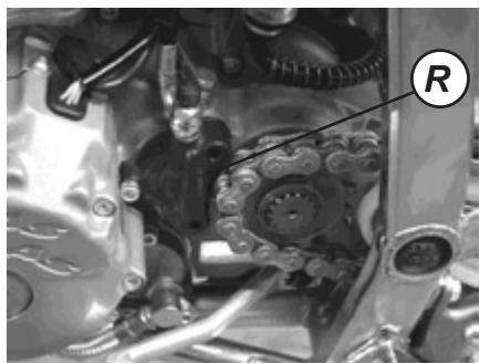
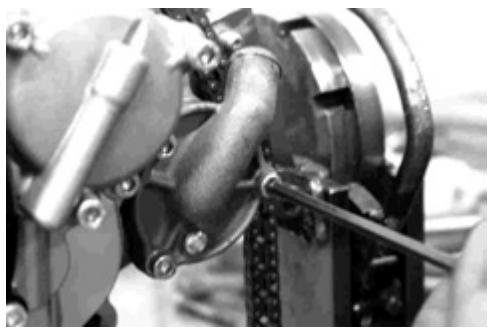
Remove the clutch cap (R). De-tense the chain.
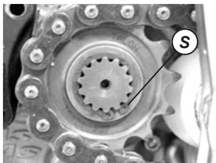
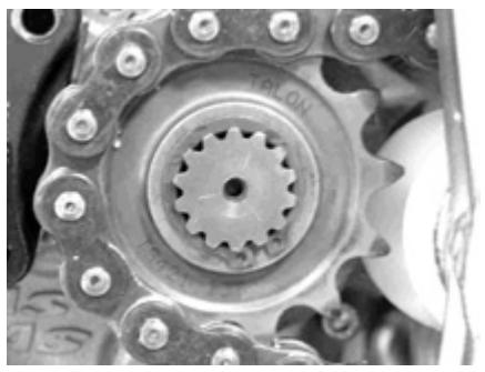
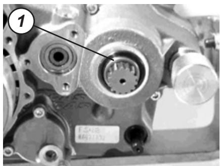
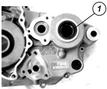
Remove the output pinion clip (S).
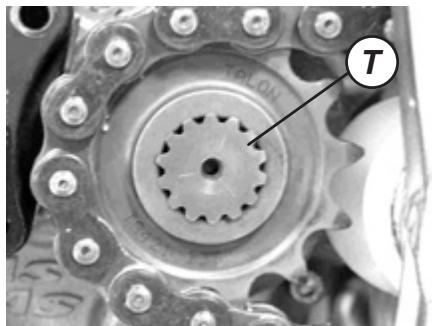
Remove the Engine pinion (T).
NOTE: Observe which is the placement direction of the said pinion.
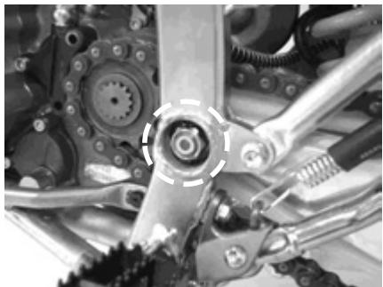
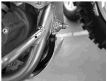
Remove the carved bolts and the brake pedal.
Remove the motor from the frame.
Fix the screws and engine fixing nuts.
NOTE: In this phase, temporarily tighten the nuts. The engine fixing nuts are self-locking. Once removed they lose their self-locking capability and are useless.
PRECAUTION Replace the engine fixing nuts with new ones.


Hold the screw heads with a spanner and tighten the engine fixing screws with the specified torque.
| Element | Nm | Kgm |
| A | 66 | 6,6 |
| B | 66 | 6,6 |
| C | 66 | 6,6 |
Length of the screws
(A): 108 mm
(B): 110 mm
(D): 103 mm
Fix the brake pedal screw with the specified torque.
Brake pedal screw: 29 Nm (2,9 Kg)
PRECAUTION Replace the carved bolts with new ones.
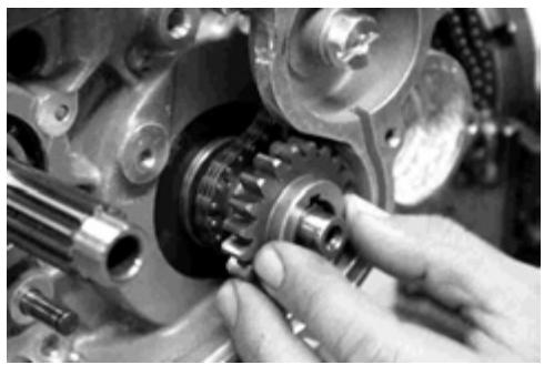
Mount the engine pinion.
NOTE: Observe which is the placement direction before the said pinion, to be able to achieve the same direction of wear.
Place the engine pinion clip.
Connect the chassis tank tube.
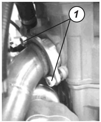
Fix the exhaust collector screw (1), with the specified torque.
NOTE: Apply component NURAL 29 in the exhaust system joints.
NOTE: Apply LOCTITE 243 to the pedal starter lever screw.
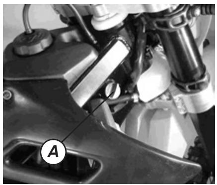
Fill 1.2 L of an engine oil classified SF or SG through the API service and with a degree of viscosity SAE 10W-40 through the oil fill mouth in the frame (A) and check the level.
DATA
Engine oil capacity
Change of oil: 1 L
Changing the oil and filter: 1.2 L
Engine general inspection: 1.2 L

3 min
Start the engine and leave it running some three minutes at idle.
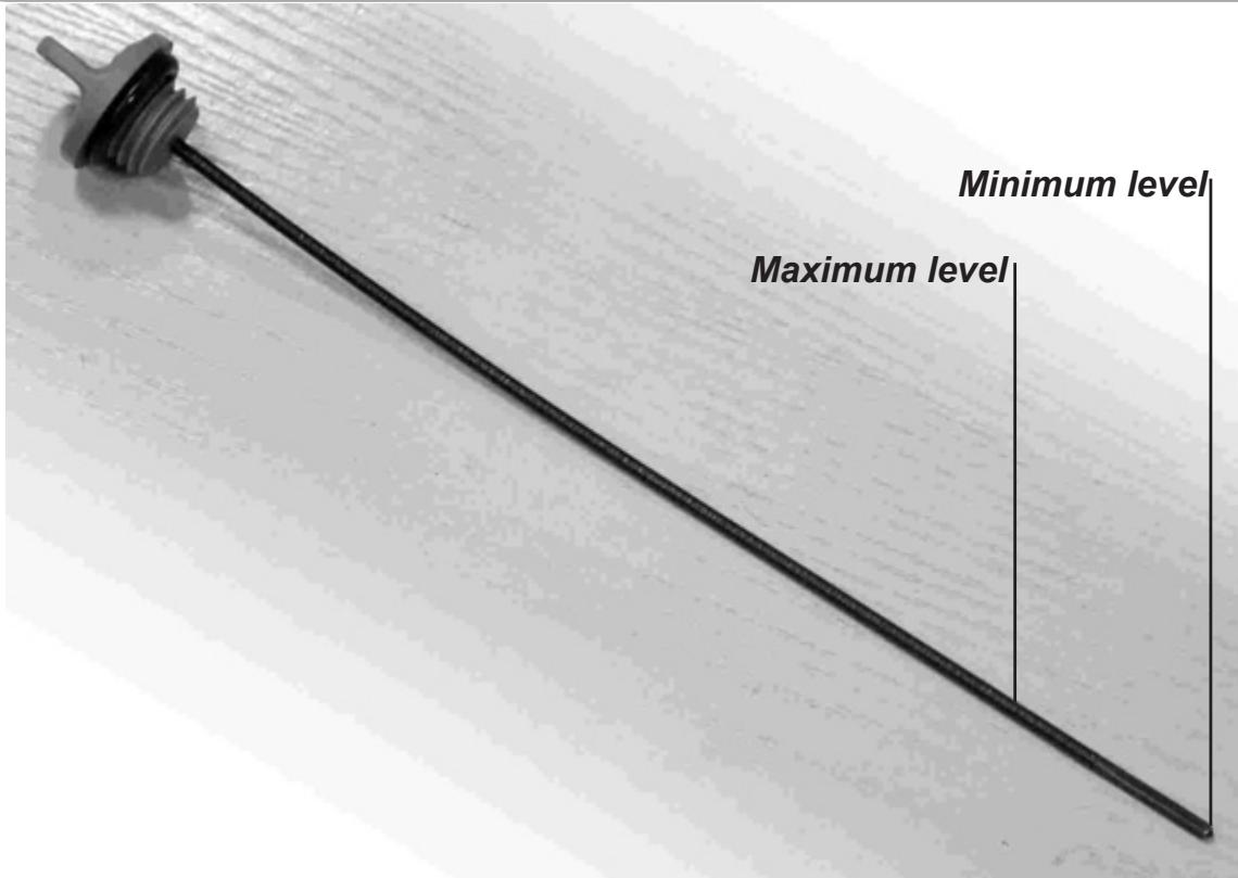
Stop the engine and wait three minutes; immediately check the oil level via the rod.
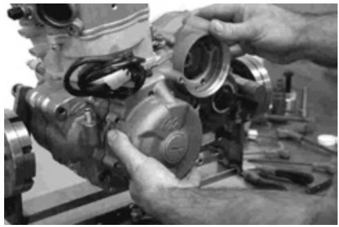
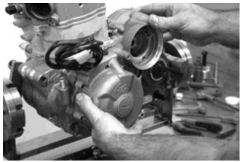
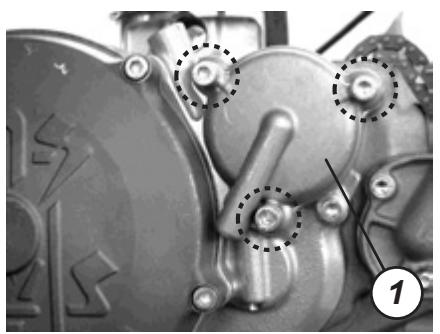
Dismounting the engine
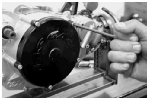
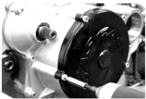
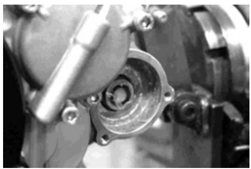
Loosen the 3 screws that hold the starter clutch cover.
One of the 3 also holds the alternator cover.
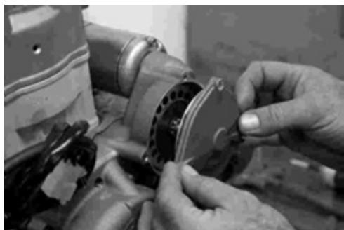
Remove the starter clutch cover.
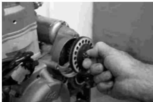
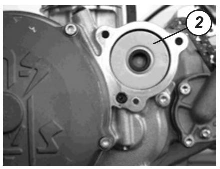
Extract the starter clutch.
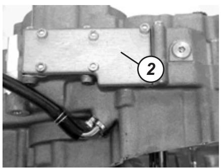
Loosen the 2 screws that hold the starter motor.

Extract the starter motor.
NOTE: The 2005 starter motor turns in the opposite direction to that of 2004.

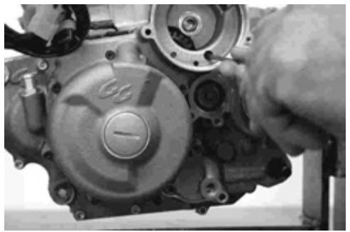
Loosen the 7 retaining screws that hold the alternator cover.
One of them is located in the starter clutch cavity.
Remove the alternator cover.
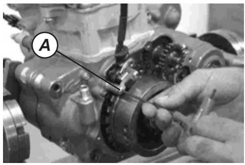
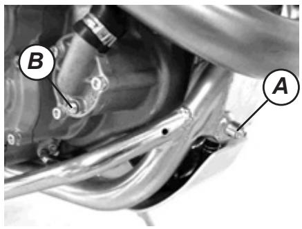
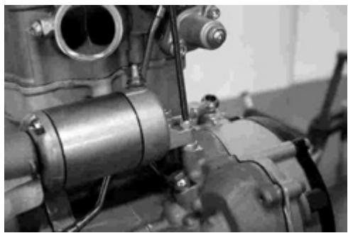
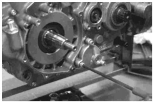
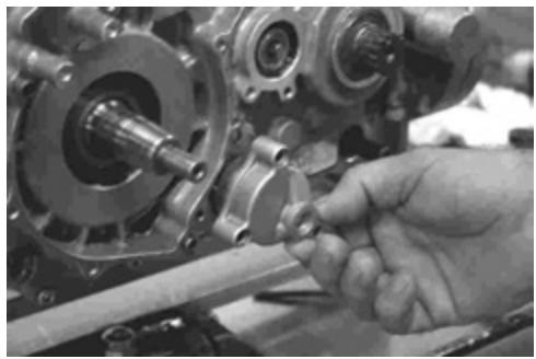
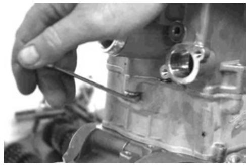
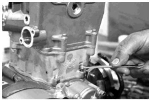
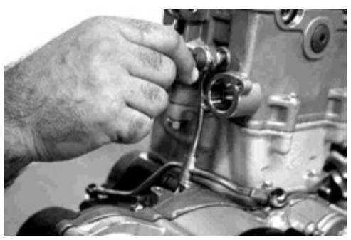
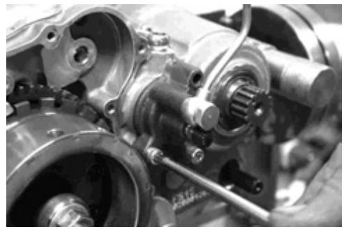
Loosen the 2 screws that hold the position sensor (Pick-Up) (A).
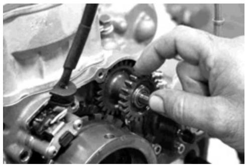
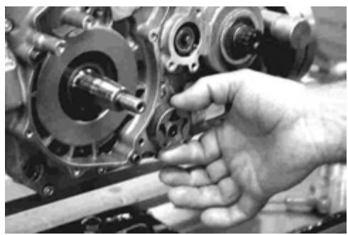
Remove the de-multiplier pinion (B).
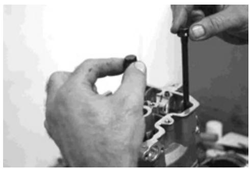
Loosen and extract the spark plug.
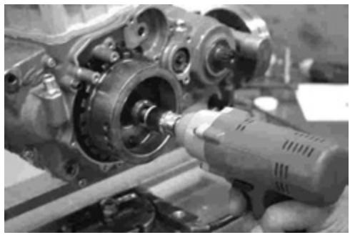
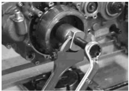
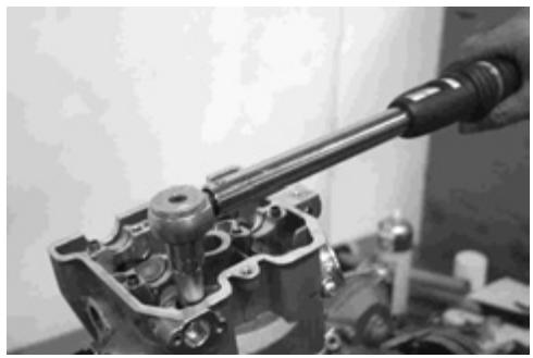
Loosen the crankshaft nut.
NOTE: The nut loosens towards the right.
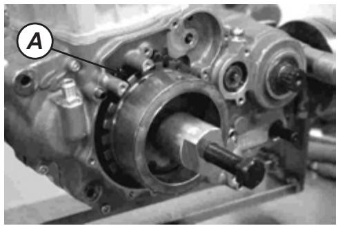
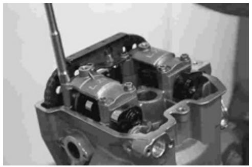
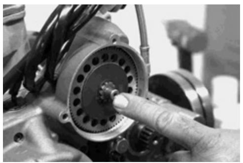
Turn the alternator rotor until placing the 7th tooth (A) of the phonic wheel in the center of the position sensor (Pick-Up) hole.
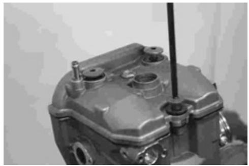
Loosen the 3 screws that hold the cylinder head cover.
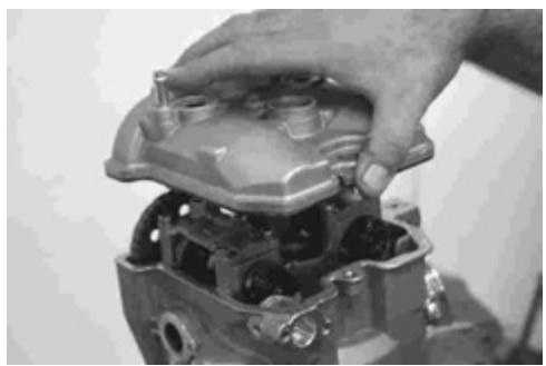
Remove the cylinder head cover.
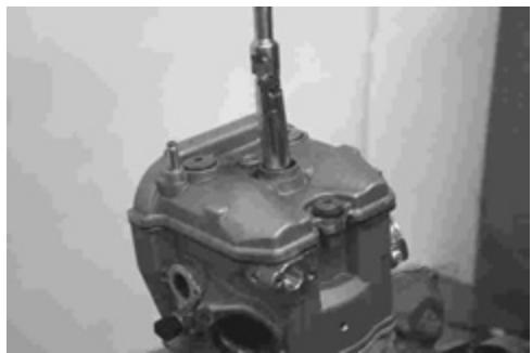
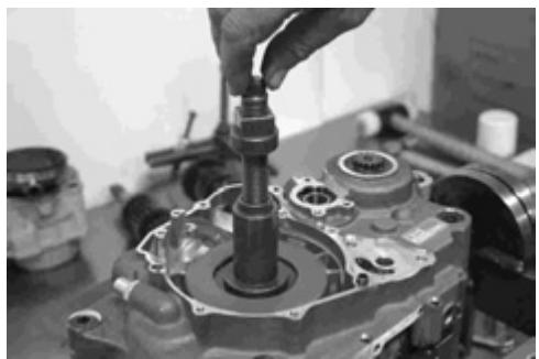
With the help of the extractor (Ref: MFS400134045), remove the alternator rotor.
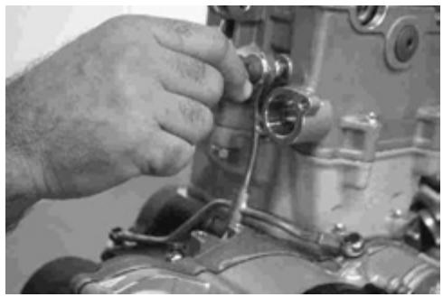
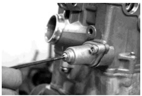
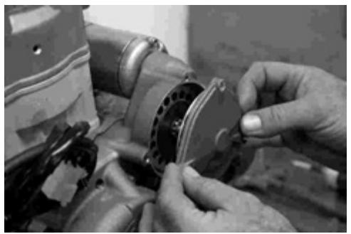
Loosen the 3 screws that hold the oil extractor pump.
Remove the oil extractor pump cover.
Remove the oil extractor pump.
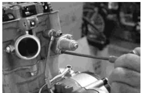
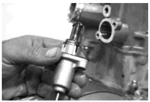
Loosen the 2 screws that hold the distributor chain tensor.
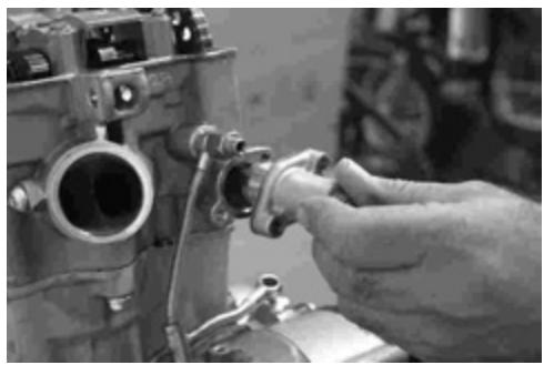
Remove the distributor chain tensor.
Remove the oil distributor.
Loosen the 2 lateral screws that hold the cylinder head to the cylinder.
Loosen the rear screw that holds the cylinder to the cylinder head.
Loosen the front screw that holds the cylinder to the cylinder head.
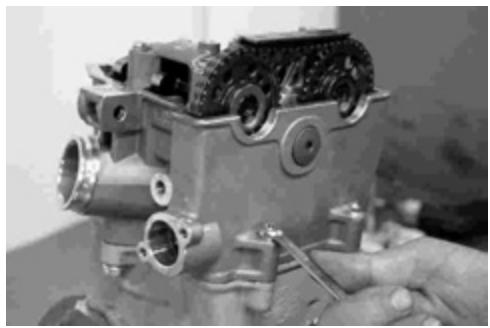
Loosen the 8 screws of the covers of the 2 camshafts and the distribution chain skate.
Remove the distributor chain upper skate.
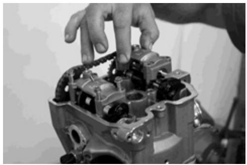
Remove the intake camshaft cover.

Remove the exhaust camshaft cover.
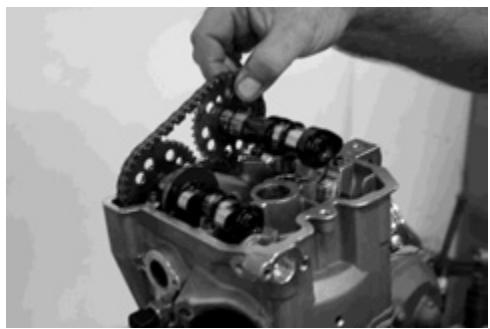
Remove the intake camshaft.
Remove the exhaust camshaft.
Loosen and remove cylinder head lateral screw.
Loosen the 4 locking screws that hold the cylinder head.
Remove the 4 screws.
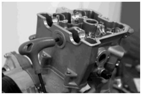
Remove the cylinder head.
Remove the cylinder head gasket.
Remove the distributor chain front skate.
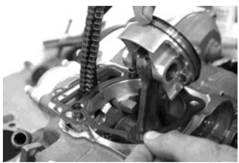
Loosen the 2 screws that hold the cylinder to the engine housing.
Hold the distributor chain and remove the cylinder.
Remove one of the clips that hold the piston casing and push to remove it.
Remove the cylinder gasket.
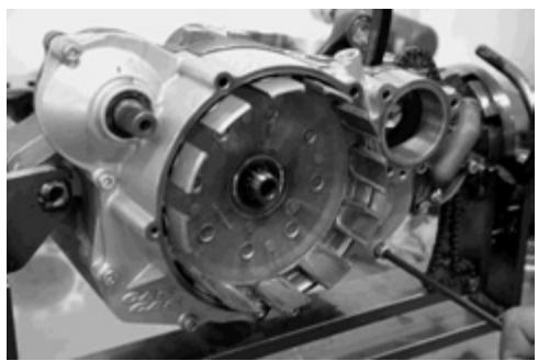
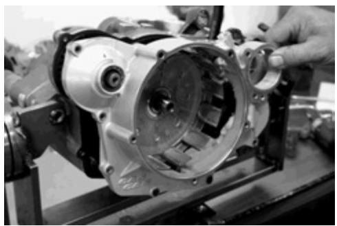
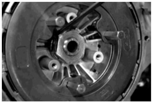
Loosen the 5 screws that hold the cover of the clutch disks.

Remove the cover of the clutch disks.
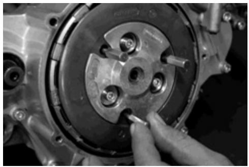
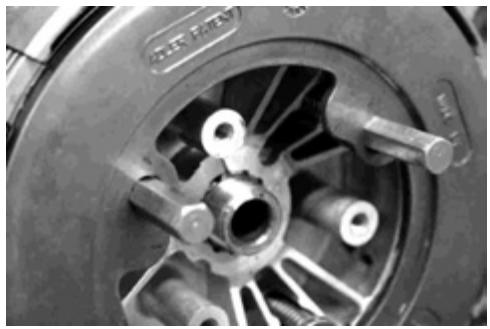
Screw the centering tools into place (supplied together with the tools for the motorbike) and tighten them to 10 Nm.
NOTE: This operation is mandatory to ensure the correct dismounting of the clutch.
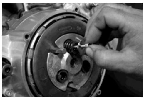
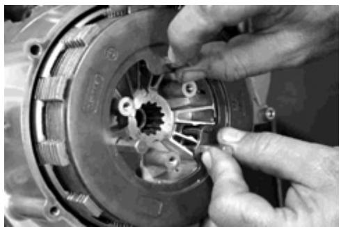
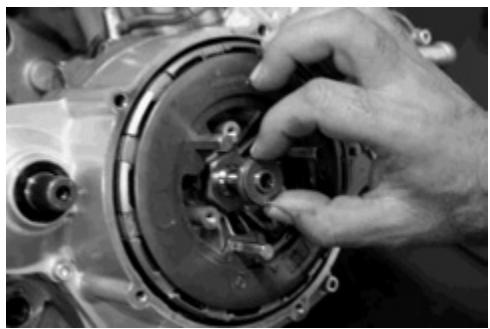
Remove the 3 screws, the 3 washers and the 3 springs that hold the clutch unit.
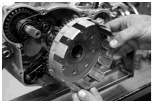
Remove the clutch press cover.
Remove the clutch pusher.
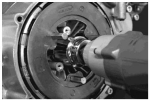
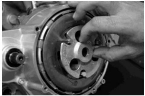
Open the washer lug.
Loosen the fixing bolt, blocking the clutch bell turn with the tool Ref. MFS4504500220.
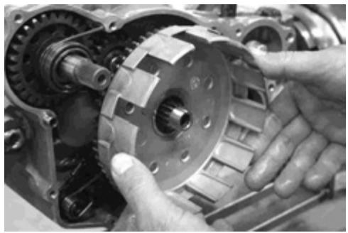
Remove the clutch unit.
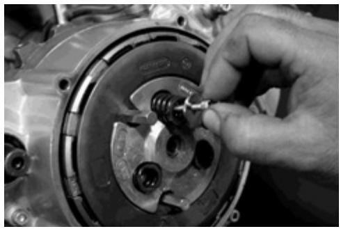
Loosen the 3 screws that hold the oil filter cover.
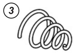
Remove the oil filter cover.
Remove the oil filter and the spring.
Loosen the screws that hold the clutch casing.

Remove the clutch casing.
Remove the clutch bell.
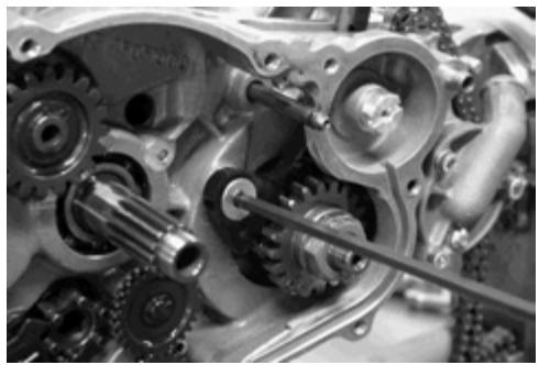
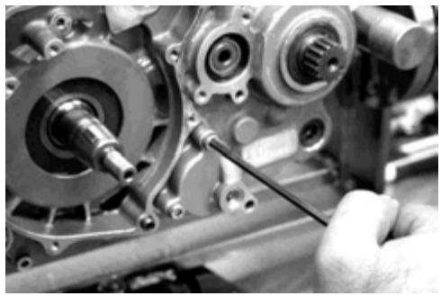
Loosen the screw that holds the distributor chain tensor skate and remove it.
Remove the gear selector axle.
Remove the gear pedal axle spring.
Remove the gear pedal axle unit.
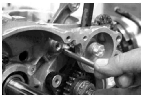
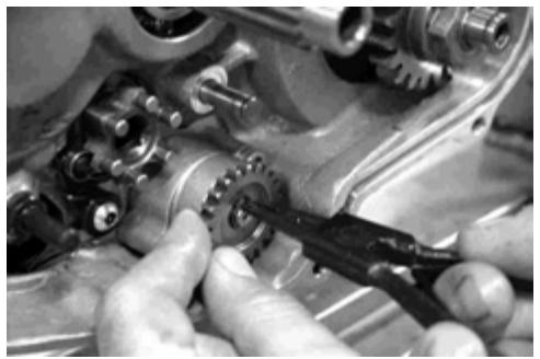
Remove the starter intermediate pinion clip.
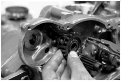
Remove the starter intermediate pinion.
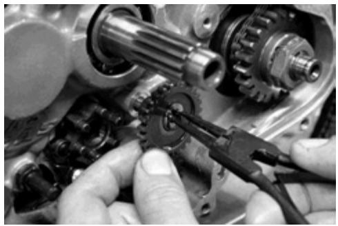
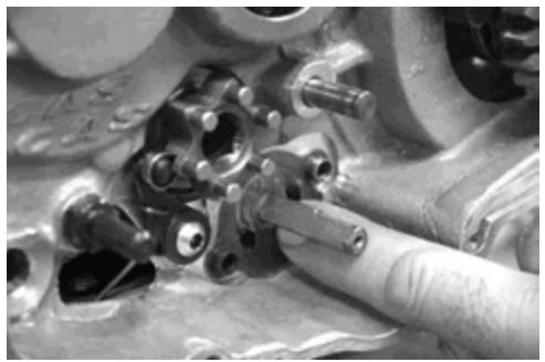
Remove the oil pump intermediate pinion.
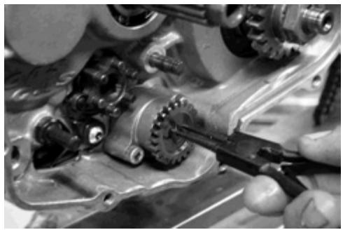
Remove the clip and remove the oil pump pinion.
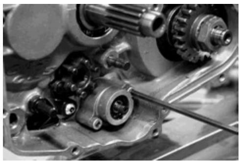
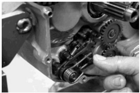
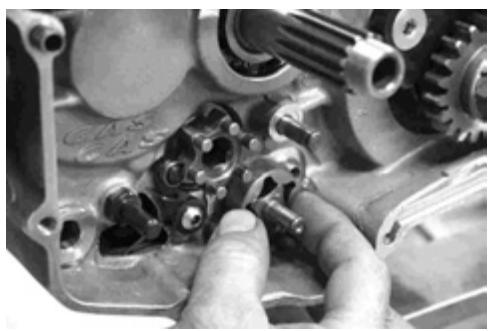
Loosen the 2 screws that hold the oil pump cover.
Remove the oil pump cover.
Remove the oil pump gasket.
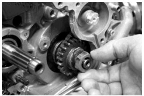
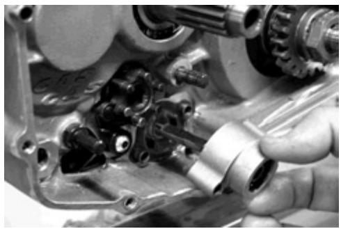
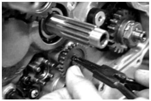
Open the washer lug and loosen the crankshaft axle nut.
NOTE: Turn the nut in a clockwise direction.
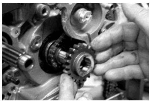
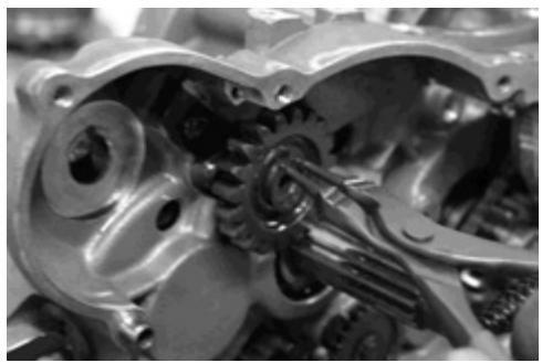
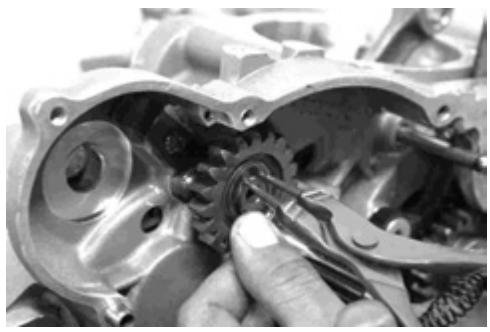
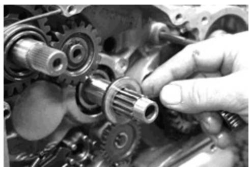
Remove the crankshaft pinion.
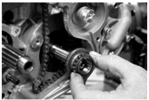
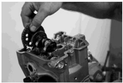
Remove the distributor chain pinion.
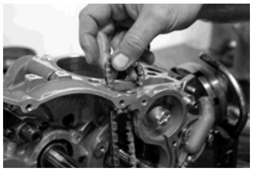
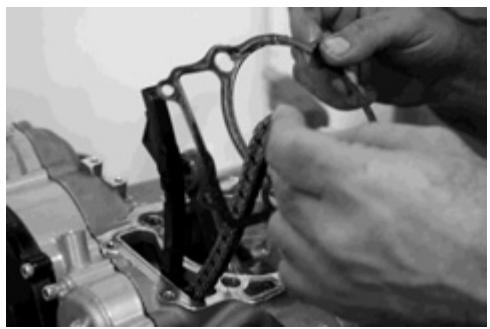
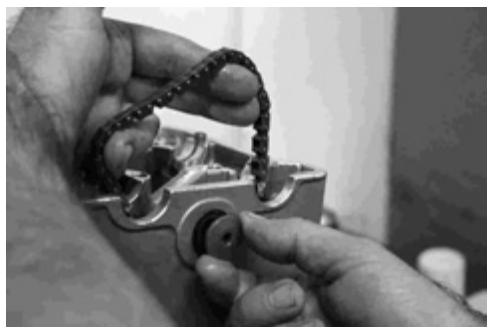
Remove the distributor chain through the upper part of the housing.

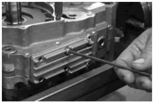
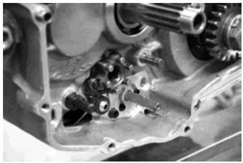
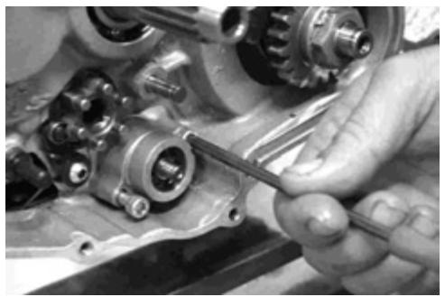
Loosen the 10 screws that hold the left housing.

One of the 10 screws that hold the left housing is located in the cavity of the oil pump.
Loosen the 6 screws that hold the oil pump filter registry cover and remove it.
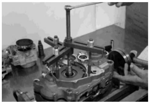
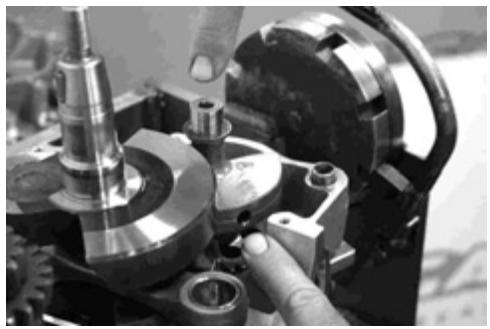
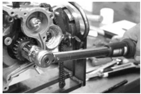
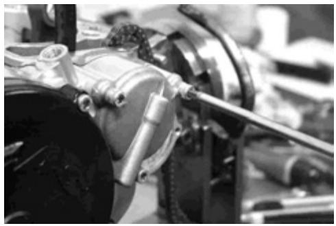
Place the extractor (Ref. ME25950005) and tighten the middle screw to separate the two housings.
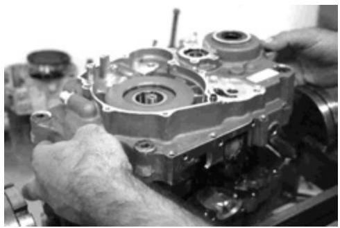
Remove the left housing.
Remove the housing gasket.
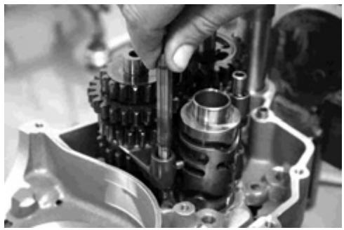
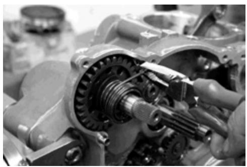
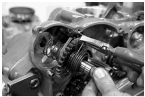
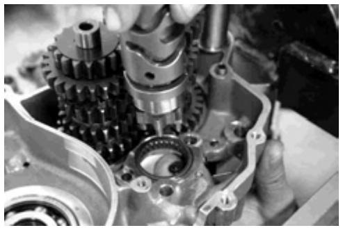
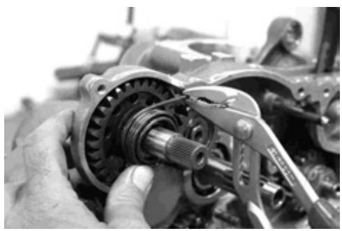
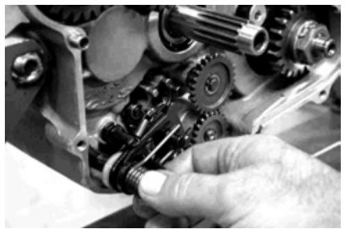
Remove the 2 axles of the gearbox pins.
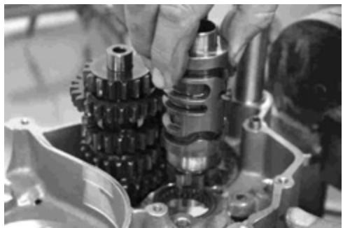
Remove the desmodrome.

Remove the gearbox gears unit.
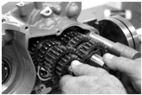
Introduce the gearbox gears unit.
Place the desmodrome.
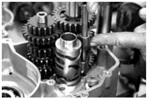
Place the 2 axles and the 2 gearbox pins.
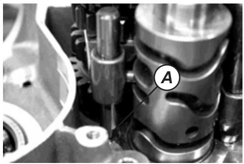
One of the pins has a groove (A) for its correct position.
NOTE: After mounting the axles of the gearbox pins and the pins, check that the gears engage normally.
Place the gears of the transmission in a dead point position.
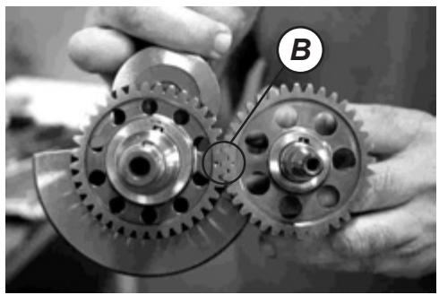
The crankshaft pinion and the balance axle pinion have a mark (B) that eases its orientation.
NOTE: Do not couple the crankshaft to the housing by tapping with a plastic hammer. Always use the special tool, otherwise the precision of the crankshaft alignment will be affected.
New engine exhaust outlet (De-vaporization model 2005).
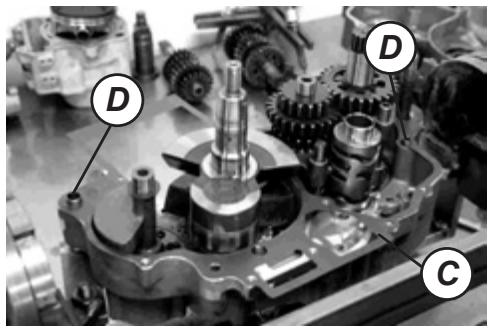
Eliminate completely the remains of sealant and oil in the contact surface of the left and right housings.
Place the new gasket (C) and the 2 guides (D) that facilitate the centering during the assembly of the two housings.
Wash the drain filter with solvent and place it.
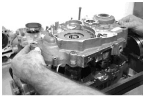
Assemble the two housings using the guides.
With the help of the tool (Ref ME25950000) press until assembling the two housings.
Place the 10 screws that fix the housing.
Apply LOCTITE in the screw that is located in the hole of the oil pump.
Housing screw: 11 Nm (1.1 kg)
NOTE:
After tightening the housing screws, check if the crankshaft, the intermediate axle and the transmission axle turn smoothly. If you detect a great resistance upon turning, try to free the axles by tapping them with a plastic hammer.
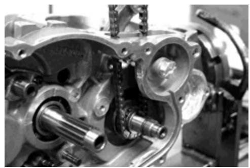
Place the chain and the distributor pinion.
Place the crankshaft cover.
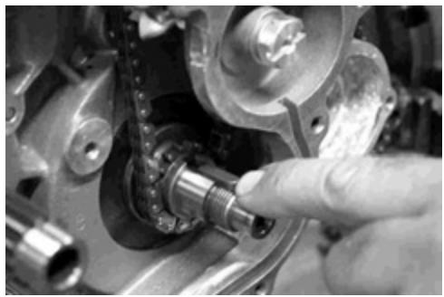
Place the crankshaft pinion.
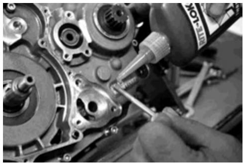
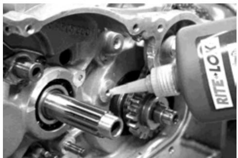
Apply LOCTITE in the hole of the screw that holds the distributor chain tensor skate.
Fix the screw that holds the distributor chain tensor skate.
Place the washer and tighten the nut with a dynamometric spanner.
Place the oil tube.
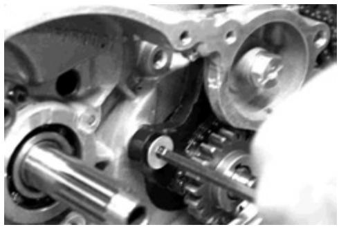
Place the starter intermediate pinion.
Place the starter unit.
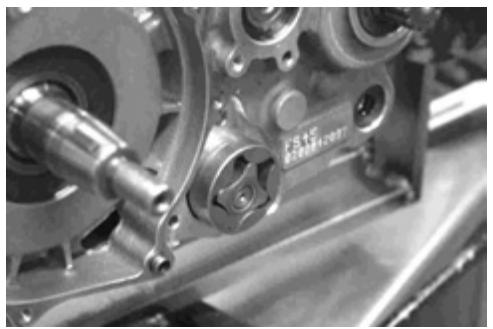
Place the oil pump axle.
Before mounting the oil pump: apply engine oil to the sliding surfaces of the pump casing, the exterior rotor, the interior rotor and the axle.
Place the engine oil pump gasket.
Place the engine oil pump.
Fix, via the 2 screws, the oil pump cover.
NOTE:
Check that it turns freely.
Place the oil pump.
Fix, via the 2 screws, the pump cover.
NOTE: Apply a small amount of LOCTITE to the threaded parts of the fixing screws of the oil pump and tighten firmly.
Place the pump pinion and fix it with the clip.
Fix the intermediate pinion of the pump with the clip.
Place the gearbox lever axle.
Place the washer.
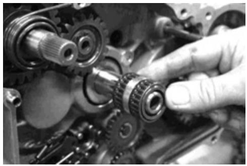
Place the bearing.
Place the clutch bell.
Place the washer.
Insert the clutch casing with a new gasket. Fix it via the screws.
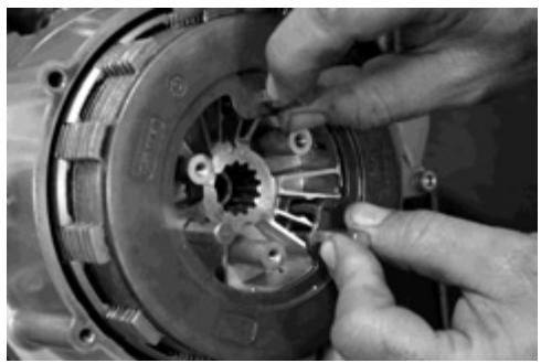
Place the clutch unit.
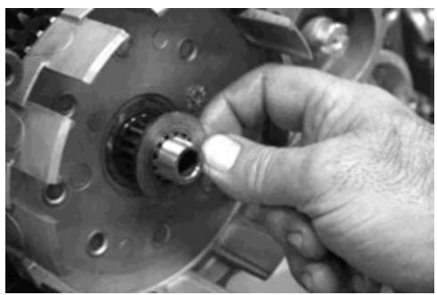
In the clutch mounting unit in the gearbox primary cam, make sure it is correctly aligned between the groove present in the interior recipient and the one in the primary camshaft of the gearbox.
NOTE: In case of an incorrect assembly the correct lubrication of the clutch unit is not guaranteed and, therefore, damage or malfunctions of the clutch unit may be produced.
Fix the fixing bolt with the security washer, blocking the clutch bell turn with the tool (Ref. MFS450450020).
Close the washer lug.
Place the clutch pusher.
Place the clutch press cover.
Place the 3 screws, the 3 washers and the 3 springs that hold the clutch unit.

Loosen, gradually, the 3 screws that fix the clutch unit.

Place the new gasket and the clutch disks cover.
Fix, via the 5 screws, the clutch disks cover.
Place the new oil filter (See maintenance chart).
Fix, via the three screws, the oil filter cover.
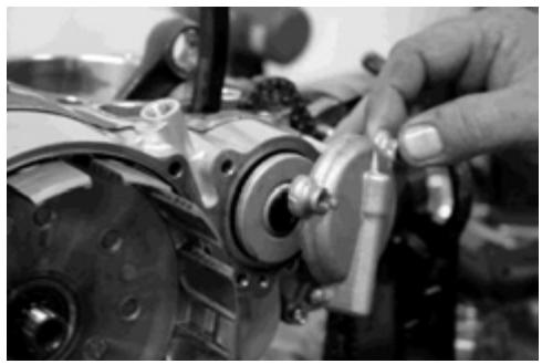
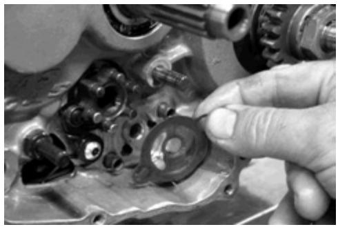
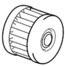
Apply oil in the water pump press.
Place the press in its position.
Place the water pump turbine and close the cover.
Check the wear of the segment.
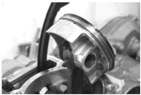
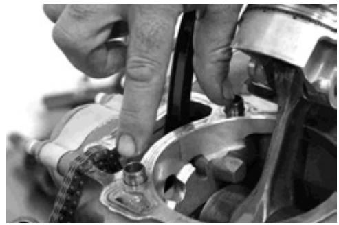
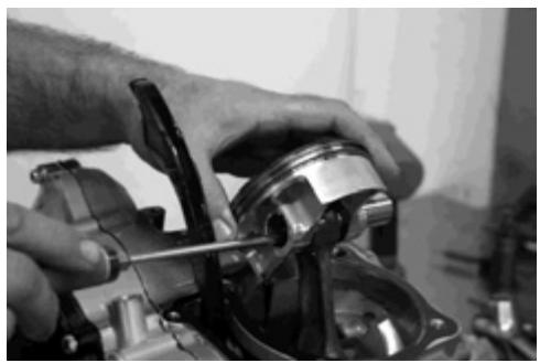
Place the piston.
PRECAUTION: Mount the piston with the mark situated in the head oriented towards the exhaust side.
NOTE: Use a new piston plastic ring to prevent it from breaking if it folds.
Place the 2 centers in the cylinder.
Place the new gasket in the cylinder base.
NOTE: Clean well the surface before placing the gasket.
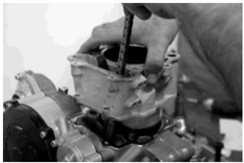
Place the cylinder.
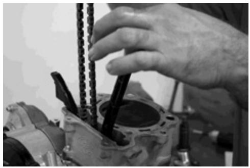
Place the piston in PMS (upper dead point) to avoid objects falling in the cylinder interior and that may damage it.
Place the distributor chain skate.
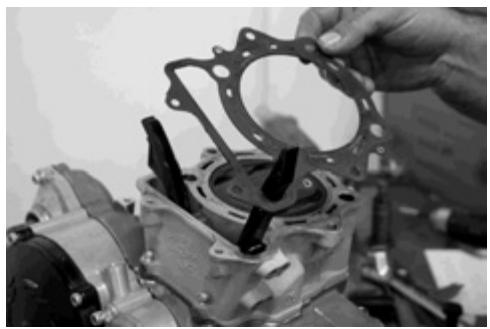
Place the 2 centers.
Place the cylinder head gasket.
NOTE: Clean well the surface before placing the gasket.
Place the cylinder head.
Place the 4 cylinder head interior fixing screws to the cylinder.
Fix, via the 4 interior screws, the cylinder head to the cylinder.
Note: Tightening torque of 4.5 Kg.
Fix, via the exterior screws located in the front and rear part, the cylinder head to the cylinder.
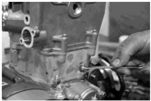
Fix, via the 4 lateral screws, the cylinder to the engine casing.
Place the lateral screw of the distributor chain.
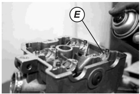
NOTE: Just before coupling the shaft axle to the cylinder head, apply a molybdenum oil solution to the stumps of the shaft axle and to the shaft surfaces. Likewise, apply engine oil to the supports of the stumps of the shaft axle (E).
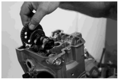
Place the exhaust cam shaft.
NOTE:
The groove of the cam shaft has a position mark.
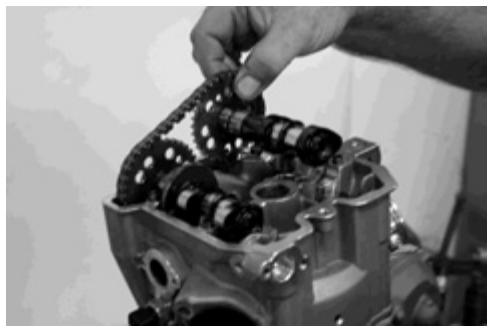
Place the intake camshaft.
NOTE:
The groove of the camshaft has a position mark.
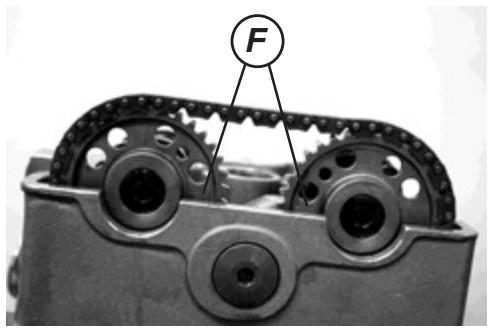
Camshaft position marks (F).
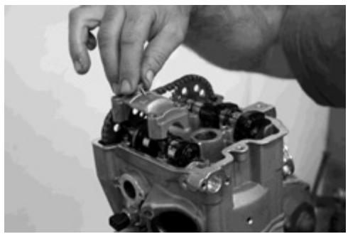
Place the exhaust camshaft cover.
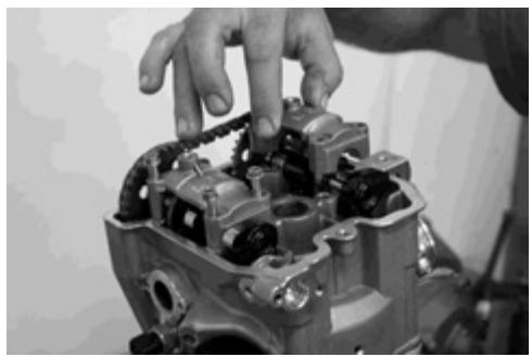
Place the intake camshaft cover.
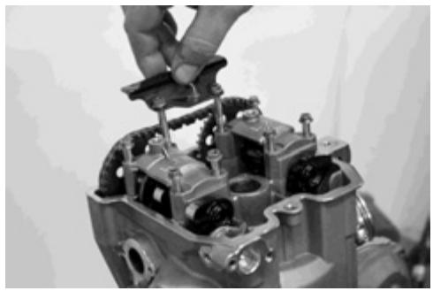
Place the distributor chain skate.
Fix, via the 6 screws, the 2 covers and the skate.
Cam axle stump support screw: 10 Nm (1 kg).
Place the oil distributor.
Adjust the distributor chain tensor.
NOTE: Use a new gasket to avoid possible oil leaks.
Distributor chain tensor spring support screw: 8 Nm (0.08 kg).
Place the distributor chain tensor.
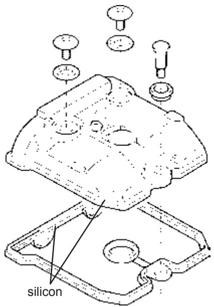
Place the cylinder head and the gasket.
NOTE: Apply silicon in the indicated zone.
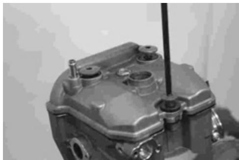
Fix, via the 3 screws, the cylinder head cover.
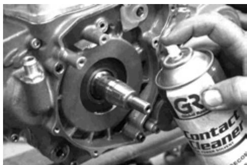
Apply a cleaning product as shown in the drawing.
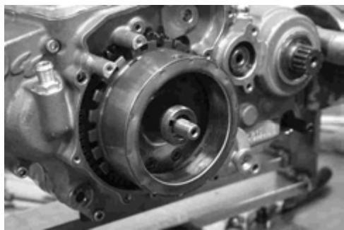
Place the alternator rotor and position the 7th tooth of the phonic wheel in the center of the hole of the position sensor (Pick-Up).
Place the clutch rod.
Place the clutch pincer.
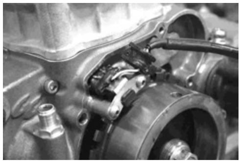
Place the position sensor (Pick-Up)
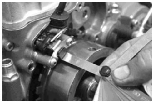
Check, via a thickness gauge, the distance between the position sensor and the rotor.

Place the de-multiplication pinion.
Place the alternator cover.
Fix the 7 screws that hold the alternator cover.
NOTE: One of them is located in the starter clutch cavity.
Place the starter clutch.
Place the starter clutch cover and fix with the 3 screws.
Introduce the starter motor and place the 2 cases of the starter motor.
CASCAS
Replacement of the standard clutch with the clutch ADLER APTC
GENERAL WARNINGS
Always shut off the engine before starting any work, in particular, when operating in closed environments without gas evacuation facilities.
Shut off the engine, remove the contact key and wait until the engine, the exhaust system and the brake unit have cooled enough to avoid burns and risk of fire. Place special attention to the parts still hot of the engine or of the vehicle (ex.: the exhaust system and the brake unit) to avoid burns.
Raise the vehicle with the corresponding means over a flat and resistant pavement.
The components and liquids coming from the vehicle should be eliminated and treated in accordance with the existing environmental laws.
To maintain maximum safety levels, it is recommended to carefully follow the instructions. Responsibility is declined for damage to persons and/or things derived from an erroneous or inappropriate mounting. The inadequate use and modification of the APTC (Adler Power Torque Clutch) clutch, aside from the erroneous mounting not performed in accordance with the instructions, lead to the automatic annulment of any existing guarantee over the product.
All the characteristics described in the present documentation, should be understood as valid for vehicles in standard conditions, without faults or anomalies.
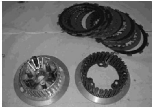
SUBSTITUTION OF THE STANDARD CLUTCH BY THE APTC ADLER CLUTCH
The clutch cube consists of two pieces united together by a special helicoidal shape. The output of the clutch is related to the torque applied.
In the acceleration phase, to the constant force of the pressure disk springs over the clutch disks package, is also added the force generated by the unit, ensuring the transmission of the engine torque with a necessary charge over the springs greatly reduced with respect to the one of the conventional clutch.
During the changing of gears, to the constant and limited force of the pressure disk springs is subtracted the force generated by the unit, ensuring the reduction of transmitted torque and the anti-bounce effect of the rear wheel.
Over the clutch control lever is perceived, in any condition of engine use, only and exclusively the load, greatly reduced, of the clutch springs applied over the pressure disk.
In the models of 450 cc 4T of enduro produced before 2004 are equipped with a conventional clutch that may be substituted by the APTC clutch performing the following operations.
Note: the following operations are performed with the engine installed in the vehicle.
Dismounting:
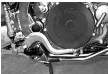
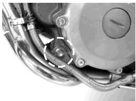
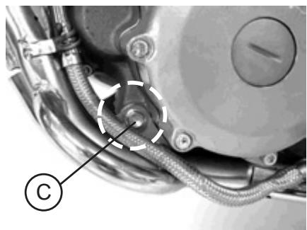
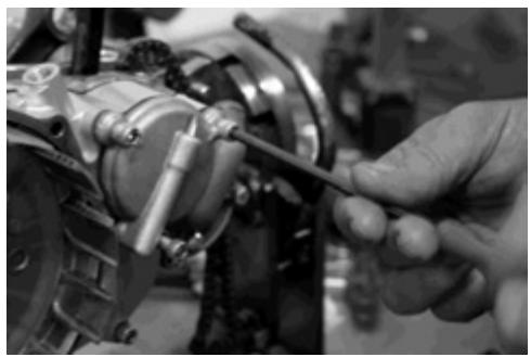
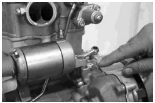
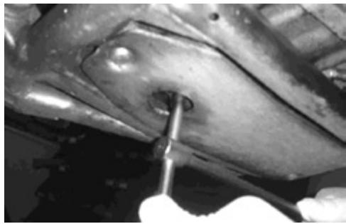
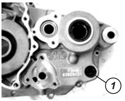
Place a recipient to collect oil below the engine and remove the sump purge screw.
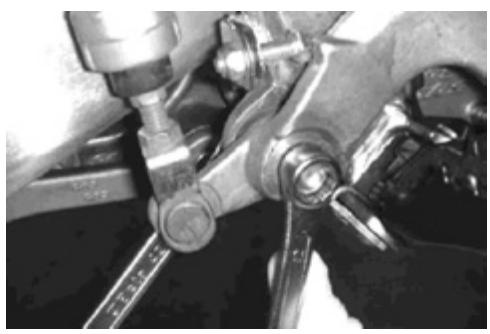
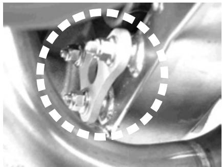
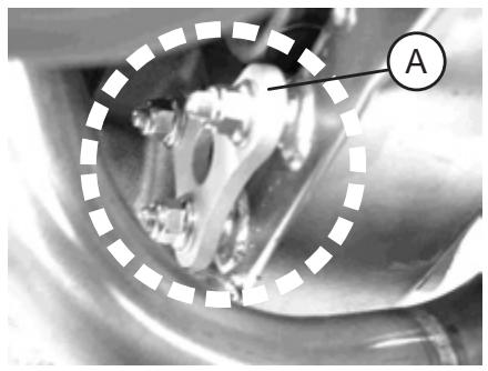
Loosen and remove the screw that fixes the brake pedal. Remove the brake pedal.
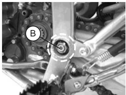
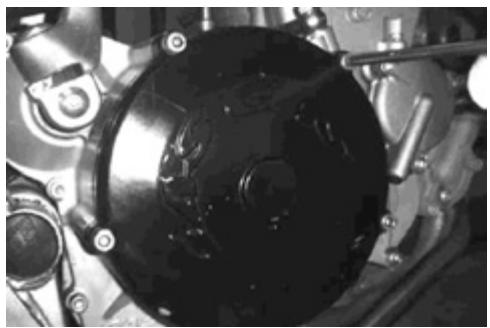
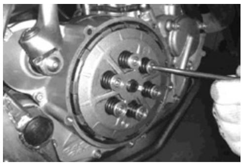
Loosen and remove the clutch cover screws.
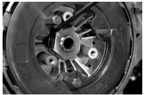
Loosen and unscrew in a cross manner the screws that fix the pressure disk springs.
Remove the screws from the pressure disk, the washers and the springs.
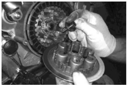
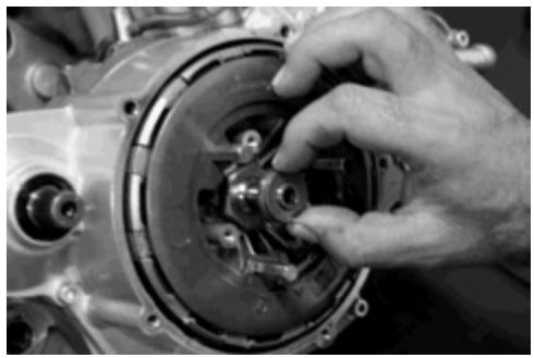
Dismount the clutch pressure disk and remove the gearbox primary cam point.
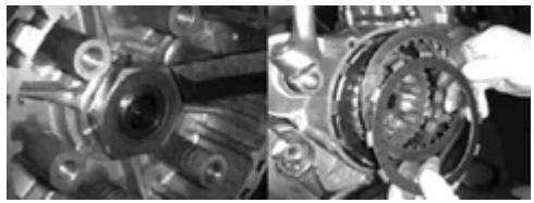
Open the security washer lug that locks the gearbox primary cam nut.
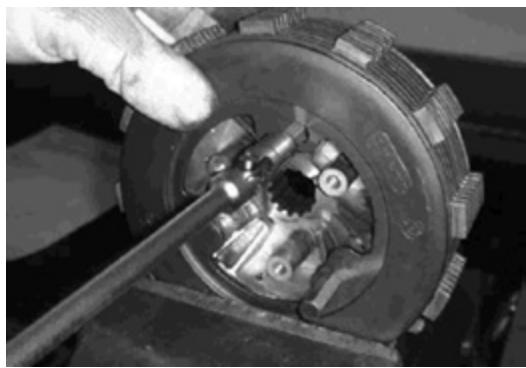
Remove the clutch disks one by one.
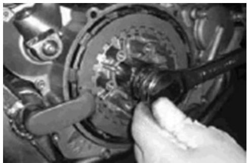
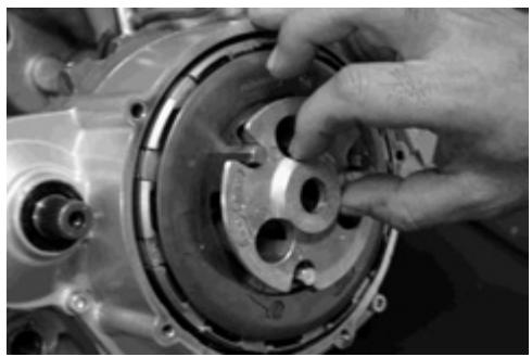
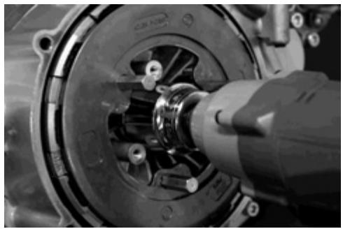
Lock the clutch pail using the special tool MFS450450020.
Loosen and remove the nut and the safety washer. Remove the special tool and remove the clutch pail from the gearbox primary cam.
ATTENTION:
The washer situated below the pail should stay on the gearbox primary cam.
Mounting:
The mounting procedure is performed as described from page 41 of this manual.
Warning:
A moderate use is recommended during the first period of use of the APTC, to allow the normal adjustment of the different components and of the clutch disks.
In case of especially intense use the APTC should be periodically subject to inspection and maintenance. The periods of this APTC maintenance depend on the conditions of use. In racing type conditions of use, the inspection and maintenance of the APTC should be performed before each competition. In normal use conditions, the APTC maintenance should be performed in accordance with the conditions defined in the user manual of GAS GAS.
CASCAS
Inspection and maintenance of the engine components
Cylinder head. 61
Cam axle unit / automatic decompressor. 73
Cylinder. 75
Piston and piston ring. 76
Connecting rod. 78
Crankshaft. 79
Starter clutch 79
Oil pump. 80
Clutch 80
Gears and gearbox pins. 82
Transmission. 83
Bearings. 84
Retainers. 88
WARNING
Identify the position of each one of the parts. Group the parts (exhaust, intake) to be able to again mount them in their original positions.
!
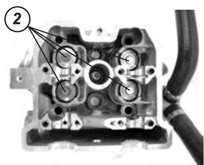
CYLINDER HEAD
Dismounting
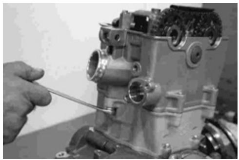
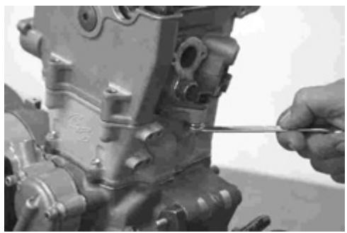
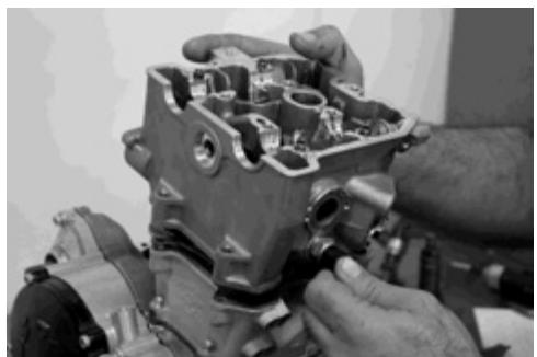
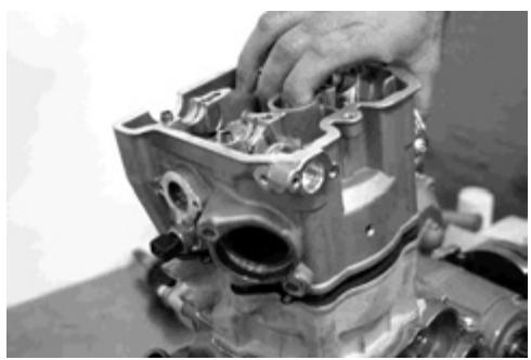
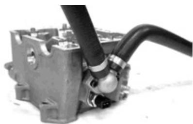
Dismount the intake tube.
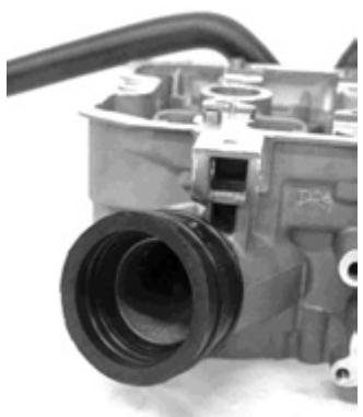
Dismount the support of the engine coolant tubes.
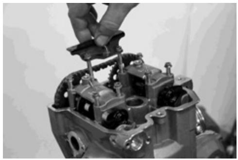
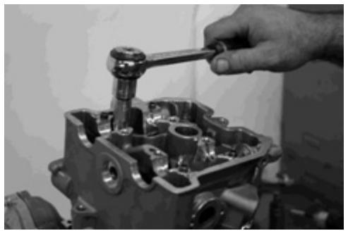
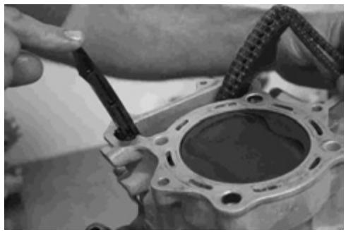
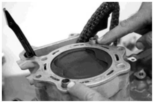
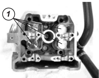
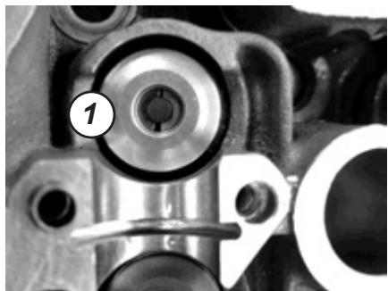
Remove the tacks (1) and the adjustment pads (2), manually or with a magnet.
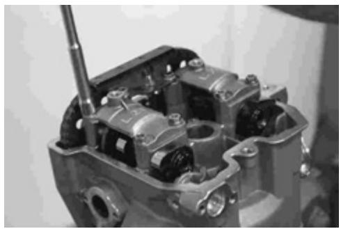
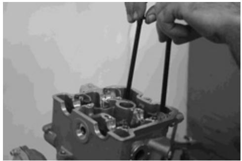
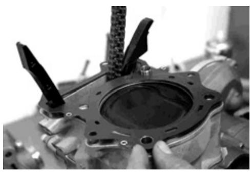
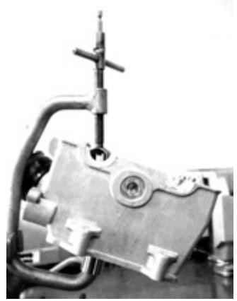
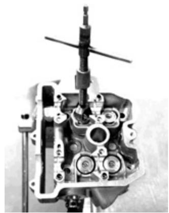
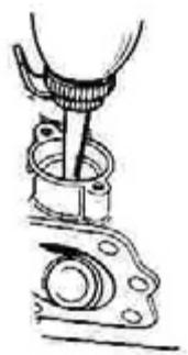
Compress the valve springs and next remove the semi-icons of the valve rod with the special tools.
Ref.: Valve spring compressor
Ref.: Adapter
Ref.: Tongs
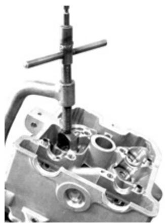
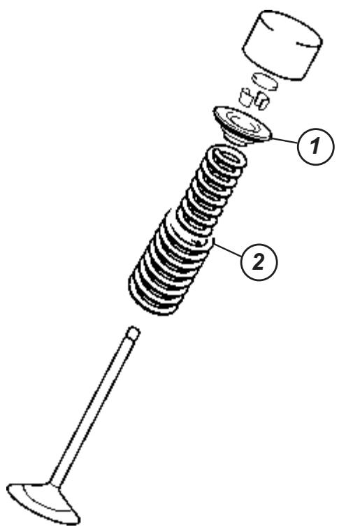
Remove the valve spring plate (1) and the valve springs (2).
Remove the valves through the cylinder head lower side.
Remove the valve retainers with some long nosed pliers.
Dismount the valve spring washers.
NOTE:
The normal dismounting work ends with the dismounting of the valves. If the valve guides have not been dismounted for its replacement after checking the associated parts, continue the described procedure in the box related to the maintenance of the guide valves.
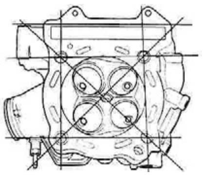
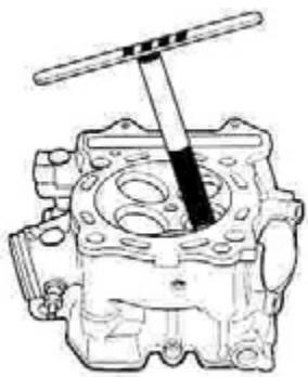
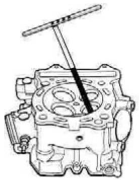
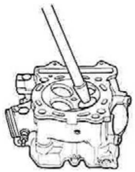
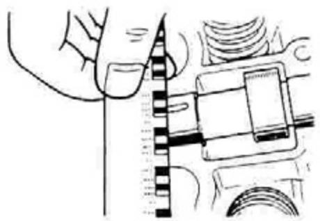
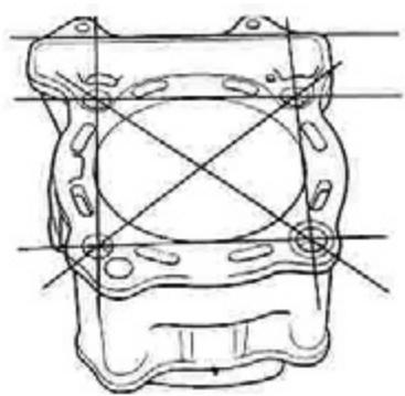
Cylinder head deformation
De-carbonise the combustion chamber.
With a ruler and thickness gauge, check if the surface of the cylinder head gasket is deformed. Measure the looseness in various places. If any of the looseness measurements surpass the service limit, replace the cylinder head with a new one.
Tool ref.:
Thickness gauge
DATA
Cylinder head deformation:
Service limit: 0.05 mm (0.002 in)
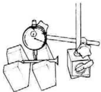
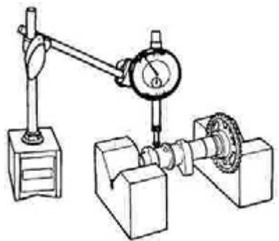
Valve rod de-centering
Hold the valve with trapezoidal locks and measure the de-centering of the rod with a quadrant gauge, as shown. If the de-centering surpasses the service limit, replace the valve with a new one.
Tool ref.:
Cuadrant gauge (1/100 mm)
Tool ref.: Magnetic support
Tool ref.: Trapezoidal lock units (100 mm)
DATA Valve rod de-centering: Service limit: 0.05 mm (0.002 in)
Valve head radial de-centering
Hold the valve with a trapezoidal lock and measure the radial de-centering of the head with a quadrant gauge, as shown. If the de-centering surpasses the service limit, replace the valve with a new one.
Tool ref.:
Cuadrant gauge (1/100 mm)
Tool ref.: Magnetic support
Tool ref.: Trapezoidal lock units (100 mm)
DATA Valve head radial de-centering: Service limit: 0.03 mm (0.001 in)


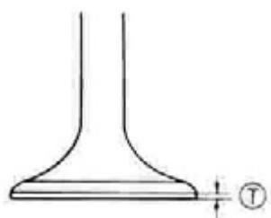
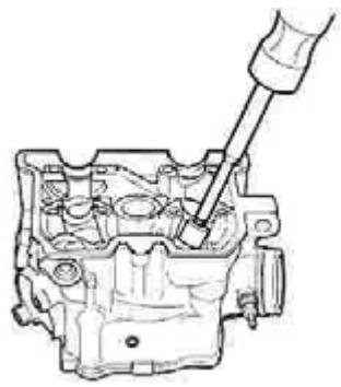
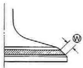
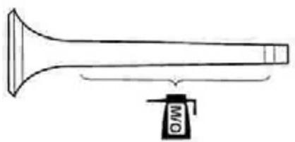
Valve work surface wear
Visually check if the work surface of each valve is worn out or damaged. If abnormal wear is detected, replace the respective valve with a new one. Measure the thickness (T) of the valve work surface. If the thickness is not found within the specified value replace the valve with a new one.
Tool ref.: Thickness gauge
DATA Valve work surface thickness (T): Service limit: 0.5 mm (0.02 in)
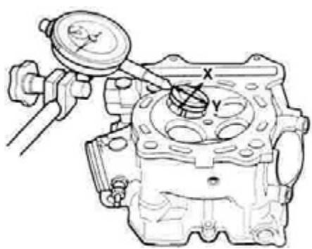
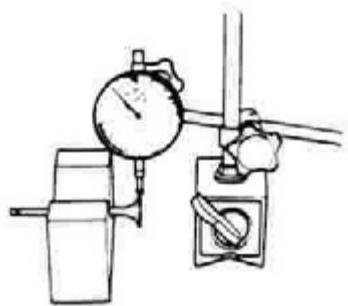
Valve rod deflection
Remove the valve some 10mm from the seat.
Measure the rod deflection in two directions, "X" and "Y", perpendicular to each other.
Place the cuadrant gauge as shown.
If the deflection surpasses the service limit, replace the valve or the guide with a new one.
Tool ref.: Cuadrant gauge (1/100 mm)
Tool ref.: Magnetic support
DATA Valve rod deflection: Service limit: 0.35 mm (0.014 in)
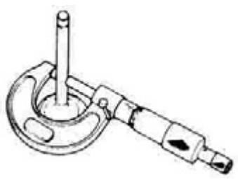
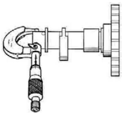
Valve rod wear
Measure the wear exterior diameter with a micrometer.
If the exterior diameter is not found within the specified value, replace the valve with a new one. If the rod exterior diameter is found within the specified value but not the deflection, replace the valve guide with a new one.
After replacing the valve or the guide, check the deflection.
Tool ref.:
Extract the valve guide towards the cam axle side with the valve guide extractor.
Tool ref.:
Extractor/valve guide mounter
NOTE:
Discard the valve guide. Oversized valve guides are only available as spares.
Rectify the valve guide holes in the cylinder head with the valve guide tool and the handle.
Tool ref.:
Valve guide tool (10.8 mm)
Tool ref.:
Tool handle
Apply oil to the rod hole of each one of the valve guides and introduce the guide in the hole with the valve guide extractor/mounter and the adapter.
Tool ref.:
Extractor/valve guide mounter
Tool ref.:
Valve guide mounter adapter
WARNING
If the valve guide hole is not lubricated before introducing the new guide, this or the cylinder head may be damaged.
After mounting the valve guides, adjust the guide interior walls with the valve guide tool. Clean and lubricate the guides after adjusting them.
Tool ref.:
Valve guide tool (5 mm)
Tool ref.:
Tool handle
Valve seating width
Paint uniformly with Prussian blue the valve seating. Mount the valve and couple to it a valve polisher. Apply light taps to the painted seating in circles to obtain a clear impression of the surface contact.
Tool ref.:
Valve polishing set
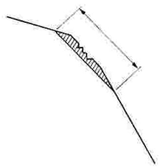
The paint impression in ring form that stays over the work surface of the valve should be continuous, without any interruption.
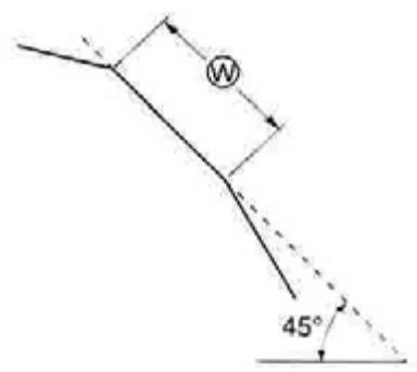
Also, the width of the paint ring, which is the width of the valve seating, should be found within the following specified value.
DATA
Width of the valve seating (W):
0.9-1.1 mm (0.035 -1.092 mm)
If the valve seating is found outside of the specified value, correct it.
Intake
Exhaust
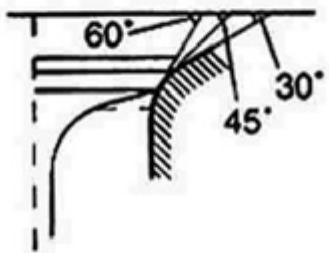
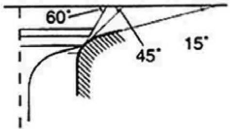
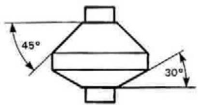
Valve seating maintenance
The intake and exhaust valve seatings are mechanised in three different angles.
The contact surface of the seating is cut at 45^ .
Intake
Exhaust
45^ N-128
15° - N-121
30^ N-128 -
60^ N-114 N-114
Tool (United States)
Vlave seating knife:
N-114, N-121 and N-128
Tools (Rest of the world)
Ref.:
Valve seating corrector unit
Ref.:
Knife N-128
Ref.:
Knife N-114
Ref.:
Knife N-121
NOTE:
Use the solid centerer together with the valve seating knives N-114, N-121 and N-128.
WARNING
After each cut you should check the valve seating contact surface.
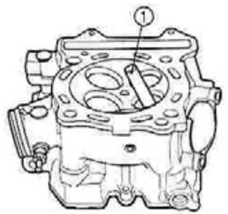
Place the solid centerer (1) and turn it lightly.
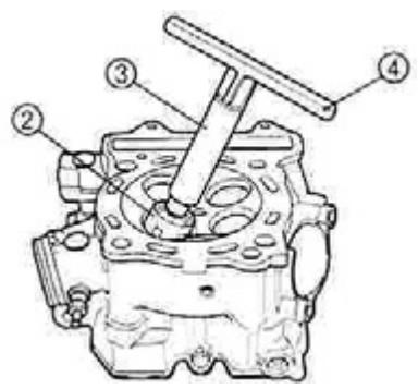
Place well the centering tool. Place the 45^ knife (2), the adapter (3) and the handle in T (4).
Initial cut of the seating
De-encrust and clean the seating with the 45^ knife. Turn the knife one or two turns.
Measure the width of the valve seating (W) after each cut.
If the valve seating is bruised or burned, use the 45^ knife to finish conditioningthe seating.
NOTE: Only cut the minimum amount necessary of the seating to prevent the possibility of having to replace the tack adjustment supplement.
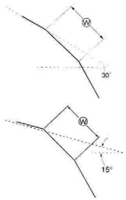
Upper width cut
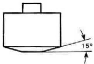
If the contact surface is too high in the valve or if it is too narrow, use the 30^ knife (intake side) and the 15^ knife (exhaust side) to lower it and make it narrow.
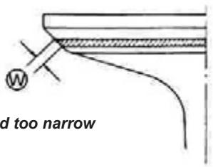
Contact surface too low and too narrow in the valve work surface.
Contact surface too low and too narrow in the valve work surface.
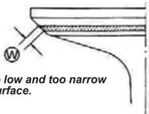
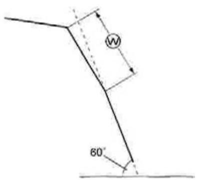
Final cut of the seating
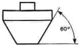
If the contact surface is too low in the valve, or if it is too narrow, use the 60^ knife to elevate it and widen it.
If the contact surface is too high in the valve or if it is too wide, use the 15^ knife to lower it and narrow it to the correct width.
Once the seating correct widths and position are obtained, use the 60^ knife very lightly to clean the shavings produced by the previous cutting operations.
WARNING
Do not use a polishing compound after having performed the final cut. The finished valve seating should present a velvety finish, but not too polished or brilliant. This would give a smooth surface for the valve final seating which will be produced during the first seconds of the engine functioning.
NOTE:
After performing the valve seating maintenance, check the tack play once the cylinder head is mounted. (2-5 to 2-8)
Valve seating hermetic status check
With the valve and the spring mounted, pour a small amount of gasoline through the leading tube of the intake or exhaust. Check that no gasoline comes out of the valve seating. If a leak is observed, correct the lock surface.
ATTENTION
The gasoline is highly flammable and explosive. Maintain heat sources, sparks and flames far from the gasoline.

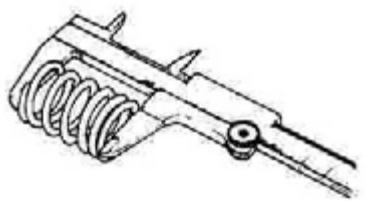
Valve spring
The helicoidal spring force maintains tightened the valve seating. With the spring weakened the engine power is reduced and a valve mechanism failure is produced.
Check the force of the valve springs, measuring its free length, as well as the force necessary to compress them. If the spring free length is lower than the service limit or if the force necessary to compress them is not found within the specified value, replace the interior and exterior springs as a set.
DATA
Spring free length (intake and exhaust) Service limit:
Interior: 32.6 mm
Exterior: 36.3 mm
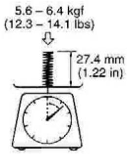
DATA
Valve spring tension (intake and exhaust)
Normal:
Interior: 5.6 - 6.4 kgf / 27.4 mm
Exterior: 12.6 - 14.5 kgf / 30.9 mm


CYLINDER HEAD
Mounting
Mount the seatings of the valve springs. Apply a molybdenum oil solution to all the valve retainers and introduce them under pressure in its position.
WARNING
Do not re-use the valve retainers.

Apply a molybdenum oil solution, as shown, and then introduce them in the guides.
WARNING
When introducing the valve in the guide, avoid damaging the valve retainer lips.

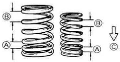
Mount the valve spring with the smaller pass end towards the cylinder head.
(A) Smaller pass
(B) Greater pass
(C) Below
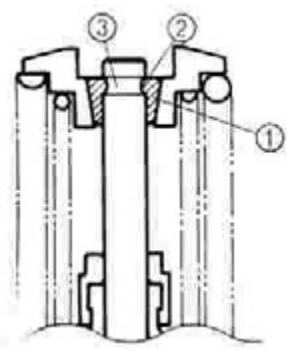
Place the spring holder by pressing it with the valve pusher. Place the semi-icons in the end of the rod and release the valve pusher so that the semi-icons (1) set in place between the holder and the rod. Check that the round lip (2) of the valve adjusts well in the groove (3) of the semicone end.
Tool ref:
Valve spring compressor

Tool ref:
Adapter
Tool ref:
Tongs
WARNING
Make sure to mount all the parts in their original positions.

AUTOMATIC DECOMPRESSOR CAM AXLE UNIT
WARNING
Do not try to disarm the automatic decompressor/cam axle unit. It can not be repaired.
Automatic decompressor
Manually move the automatic decompressor counterweight to check if it works smoothly. If the automatic decompressor counterweight does not function smoothly, replace it with a new one.
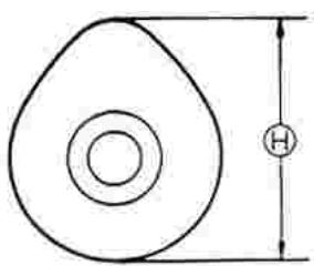
Cam wear
The wearing of the cans usually provokes the misalignment of the valve adjustment, with the corresponding power loss.
Measure the height (H) of the cam with the micrometer.
If the wear surpasses the service limit, replace the cam axle with a new one.
Tool ref:
Micrometer (25-50 mm)
DATA
Cam height (H)
Intake: 36.934 mm
Exhaust: 36.893 mm
Service limit:
Intake: 36.634 mm
Exhaust: 36.593 mm
Cam axle bridge wear
With the cam axle mounted, measure the width of the oil with the plastic tool.
Tools
Ref.:
Plastic tool
DATA
Cam axle bridge oil width
(intake and exhaust)
Service limit: 0.150 mm
Tighten the bridge support screws uniformly and in diagonal sequence with the specified torque.
Cam axle bridge support screw:
10Nm (1kgm)
NOTE:
Do not turn the cam axle with the plastic tool placed.
Dismount the supports of the stumps and measure the width of the plastic tool compressed with the surrounding ruler. This measurement should be performed in the wider part of the compressed plastic tool. If the cam axle bridge oil width surpasses the service limit, measure the bridge support interior diameter and the bridge exterior diameter.
Replace the cam axle or the cylinder head and the cam axle support, depending on which one exceeds the specified value.
Tool
Ref.:
Lower calibration gauge
DATA
Cam axle bridge support interior diameter (intake and exhaust)
Normal: 22.012 - 22.025 mm
Tool
Ref.:
Cam axle bridge exterior diameter (intake and exhaust)
Normal: 21.972 - 21.993 mm
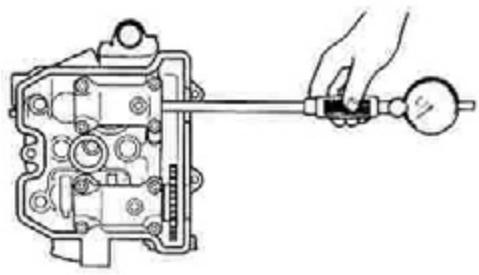
Cam axle de-centering
Hold the valve with trapezoidal locks and measure the de-centering of the cam axle with the cuadrant gauge. If the de-centering surpasses the service limit, replace the cam axle with a new one.
Tools
Ref.:
Cuadrant gauge (1/100 mm)
Ref.:
Magnetic support
Ref.:
Trapezoidal lock units (100 mm)
DATA
Cam axle de-centering.
Service limit: 0.10 mm
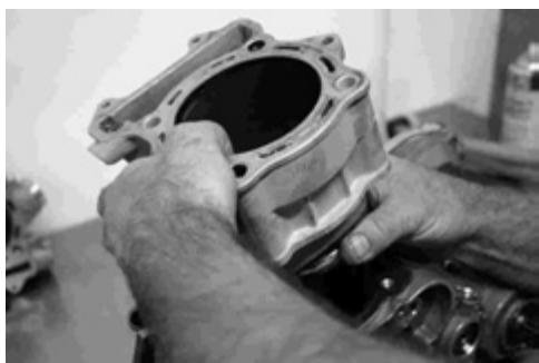
CYLINDER
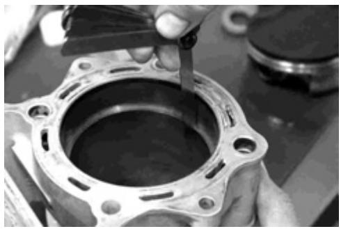
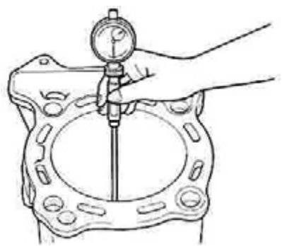
Cylinder deformation
With a ruler and thickness gauge, check if the surface of the cylinder block gasket is deformed. Measure the looseness in various places. If any of the looseness measurements surpass the service limit replace the cylinder block with a new one.
Tool ref.:
Thickness gauge
DATA
Cylinder deformation
Service limit: 0.05 mm (0.002 in)
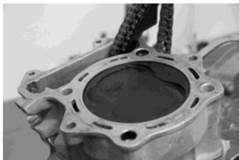
Cylinder interior wall
Check if the cylinder interior wall presents
scratches, nicks or other damage.
Measure the cylinder interior diameter in six places.
Tool
Ref.:
Cylinder gauge unit
DATA
Cylinder interior diameter
FSE 400: 90.000 - 90.015 mm
FSE 450: 95.000 - 95.015 mm
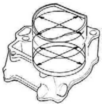
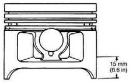
Fig.1
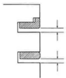
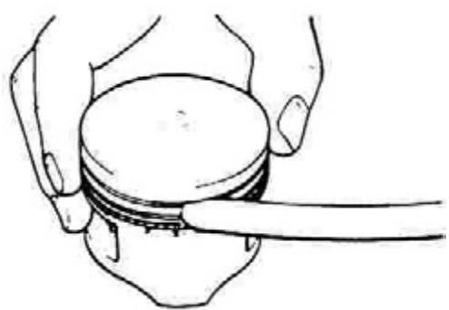
Fig.2
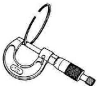
Fig.3
PISTON AND PISTON RING
Piston diameter
Measure the piston diameter with a micrometer at 15mm of the end of the skirt. If the piston diameter is lower than the service limit, replace the piston with a new one.
Tool ref.: Micrometer (75-100 mm)
DATA
Piston diameter
Service limit FSE 400: 89.880 mm
Service limit FSE 450: 94.880 mm
Space between the piston ring and the groove
Measure the side spaces of the 1st and 2nd piston rings with the thickness gauge. If any of the spaces exceeds the service limit, replace the piston and the rings.
Tool ref.: Thickness gauge
DATA
Space between the piston ring and the groove
(Fig.1)
Service limit: 1^ :0.18 mm (0.0071 in) 2^ : 0.15 mm (0.0059 in)
DATA Piston rings groove width (Fig. 2)
Normal: FSE 400 1^ : 1.03 mm 2^ : 1.22 mm
FSE 450
1°: 1.23 mm
2°: 1.53 mm
Lubrication: 2.01 -2.03 mm
Tool ref.: Micrometer (0-25 mm)
DATA Piston rings thickness (Fig. 3) Normal:
FSE 400
1°: 0.985 mm
2°: 1.19 mm
FSE 450
1°: 1,19 mm
2°: 1.49 mm
76 Inspection and maintenance
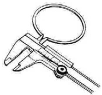
Fig.4
Free piston ring end aperture and piston ring end aperture
First measure the piston ring free end aperture with the calliper and then place the piston ring transversally in the cylinder and measure the aperture of the ring end with the thickness gauge.
Tool ref.:
Thickness gauge
DATA
Aperture of the free piston ring end
(Fig. 4)
Service limit:
Piston bolt holder and bolt interior diameter
Measure the piston bolt holder diameter with a small calliper. If the diameter surpasses the service limit, replace the piston with a new one.
Tool ref.:
Cuadrant gauge (1/1,000 mm)
Tool ref.:
Small calliper (18-35 mm)
DATA
Piston bolt holder interior diameter
Service limit: 20.030 mm
Measure the piston bolt holder exterior diameter in three places, with the micrometer. If any of the measurements surpasses the service limit, replace the piston with a new one.
Tool ref.:
Service limit: 19.980 mm
CONNECTING ROD
Connecting rod foot interior diameter
Measure the connecting rod foot interior diameter with the small calliper. If the interior diameter of the connecting rod foot exceeds the service limit, replace the connecting rod with a new one.
Tool ref.: Cuadrant calibrator compass
DATA Connecting rod foot interior diameter Service limit: 20.040 mm

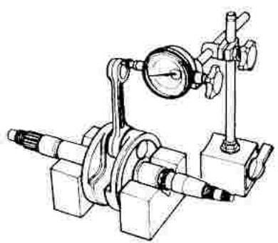
Connecting rod deflection and connecting rod side space
The connecting rod head wear may be estimated by checking the movement of the connecting rod foot. This method may be also used to check the degree of wear of the connecting rod head parts.
Tool ref.: Magnetic support
Tool ref.: Cuadrant gauge (1/100 mm)
Tool ref.: Trapezoidal lock units (100 mm)
DATA Connecting rod deflection Service limit: 3 mm

Push the connecting rod head to one side and measure the side space with a thickness gauge. If the space exceeds the service limit, replace the crankshaft unit with a new one or correct the deflection and the side space within the service limit replacing the worn parts (connecting rod, connecting rod head bearing, crankshaft bolt, etc.)
Tool ref.: Thickness gauge
DATA Connecting rod head side space Service limit: 1 mm


CRANKSHAFT
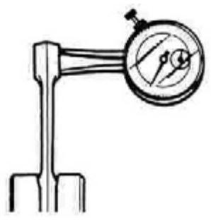
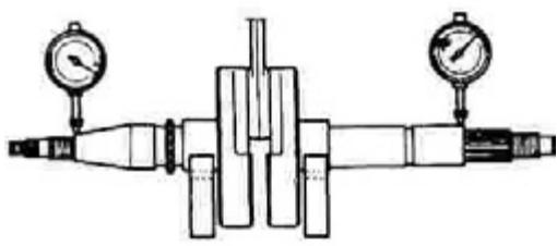
Crankshaft de-centering
Hold the crankshaft with trapezoidal locks and measure the de-centering with a quadrant gauge, as shown. If the de-centering surpasses the service limit, replace the crankshaft with a new one.
Tool ref.: Cuadrant gauge (1/100 mm)
Tool ref.: Magnetic support
Tool ref.: Trapezoidal lock units (100 mm)
DATA Crankshaft de-centering Service limit: 0.08 mm
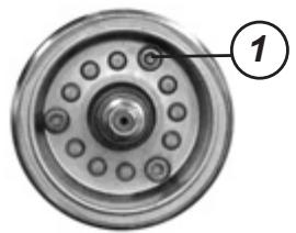
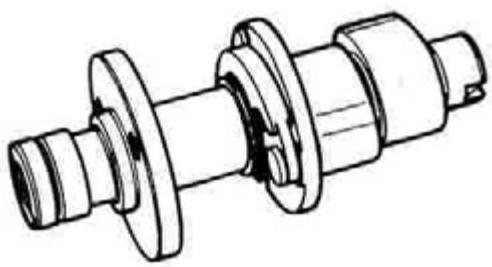
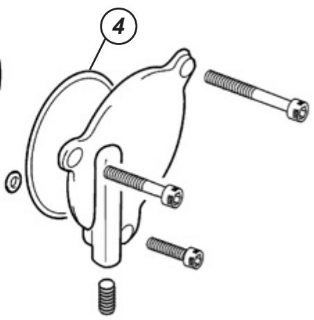
STARTER CLUTCH
Remove the hexagonal screws (1).
Starter clutch screw: 26 Nm (2.6 kgm)
Nount the starter clutch in the correct direction, as shown.
Apply engine oil to the starter clutch.
Apply LOCTITE to the hexagonal screws and later tighten with the specified torque while holding the rotor with a spanner.
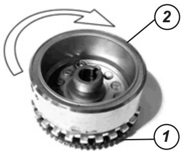
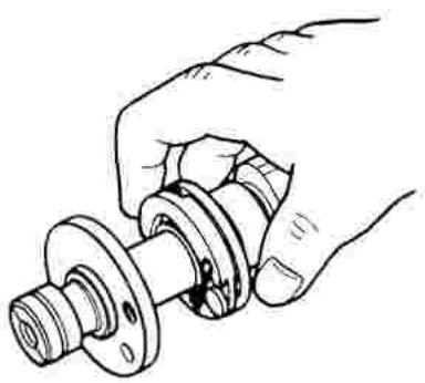
Couple the gears (1) to the starter clutch.
Check that the rotor (2) turns in the direction indicated by the arrow while holding the gears and pay attention so that the rotor never turns in the opposite direction to that of the arrow.
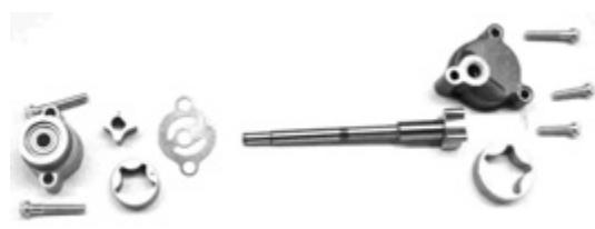
OIL PUMP
Check all the components.
The screws that fix the pump to the engine sump should be placed with LOCTITE and a specified torque.
Oil pump: 10 Nm (1.0 kgm)
CLUTCH
Place the clutch unit in a bench press using protective gags. Gradually loosen the 3 assembly screws and unscrew them completely.
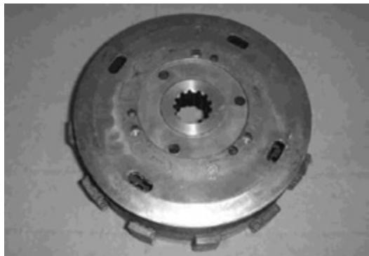
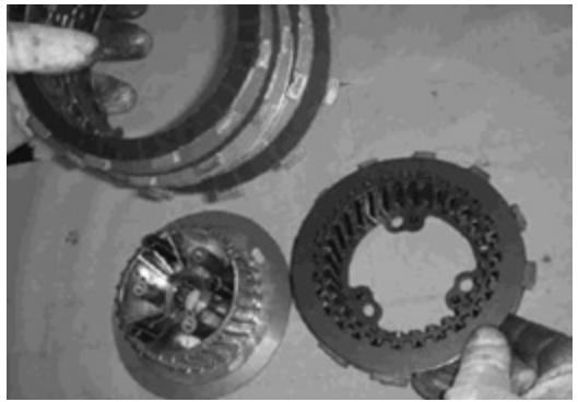
Remove the clutch unit from the press and support it over a clean work surface with the interior pail upwards, as shown in the image.
Remove carefully the interior pail from the exterior.
Place the interior pail over the bench with the arrow directed in the direction contrary to the operator.
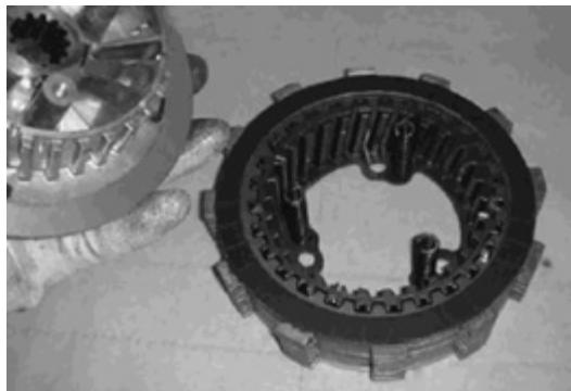
Remove the aperture springs of the APTC pails that stayed in the exterior pail and introduce them in the interior pail.
Remove the conductors and conducting disks from the interior pail of the clutch unit. Carefully clean all the clutch unit components. It is preferable to use detergents similar to percloretylene (PCC).
After the cleaning, dry all the components using compressed air.
Check the wear of all the components and replace the damaged or worn out components using original GAS GAS.
Notes:
Do not use pointed tools or aggressive detergents to clean the components of the clutch unit, since some of the surfaces of the same components are covered with an anti-wear covering with low friction coefficients.
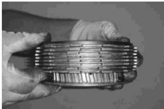
The conducting and conducting disk package should be replaced when the total package thickness of the 8 covered conducting disks is lower than 21mm .
The thickness of the 8 covered conducting disks lower than 21mm does not guarantee the correct functioning of the clutch unit.
The use of non-original GAS GAS components does not guarantee the correct functioning of the clutch unit.
Before assembling the clutch unit it is necessary to lubricate all the components using oil for engines conforming to the GAS GAS prescriptions.
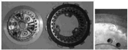
Support the exterior pail over a flat surface, as shown in the image, and introduce alternately the 8 covered conducting disks and the 7 conducted disks starting with a covered conducting disk.
Support in the work bench the interior pail with opening springs in the upper part.
Maintain pressed the disk package with the fingers against the exterior pail and over turning it, introduce it in the interior pail taking care in making sure that the reference marks of bothpails coincide. Tighten the interior pail with the clutch disks corresponding to the positions of the opening springs in the exterior pail. Make sure that the opening springs are correctly placed in their seating in the exterior pail. Without stopping the clutch disk package pressure with the fingers, also hold the exterior pail.
WARNING: Check that the upper conductive disk is not moved nor slides outside of the exterior pail.

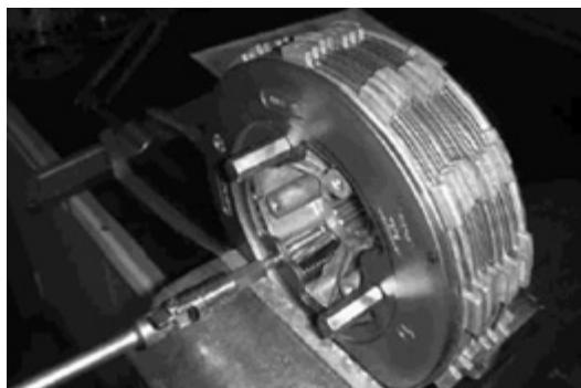
Without letting go of the pressure on both pails, tighten the clutch unit in a bench press with protective gags.
Tighten lightly to close the screw.
Screw the three assembly screws and remove the clutch unit from the bench press.
WARNING:
Make sure that the conductive disk on the fixed pail side does not move and does not fall from the moving pail teeth.
WARNING: Do not fully tighten the assembly screws, in a manner that it would be possible to ensure the possibility of movement relative to the conducting disks in the clutch unit group.


SPEED GEARBOX PINS AND GEARs
Space between the pin and the pin groove
The space of each gearbox pin plays an important role in the smoothness and positive functioning of the gearbox.
Measure the space of the pins in the groove of their respective seatings, with the thickness gauge. If the space exceeds the specified value, change the pin, its respective seating or both.
Tool ref.: Thickness gauge
Tool ref.: Thickness gauge
DATA
Space between the pin and the pin groove
Service limit: 0.50 m

DATA
Gearbox pins groove width
Normal: 4.8 -4.9 mm
DATA
Gearbox pins thickness:
Normal: 4.6 -4.7 mm
TRANSMISSION
Dismounting
Dismount the transmission gears as shown.
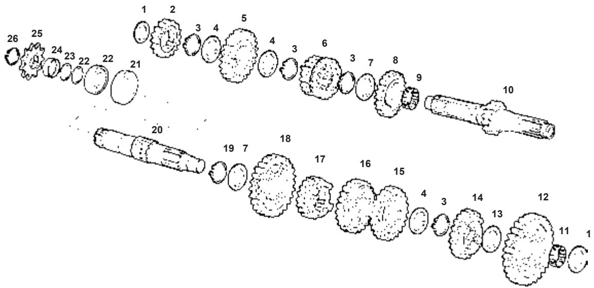
01) washer 18x31.5x0.7 gearbox
02) primary pinion II
03) circlip d.25 din 471 reduced
04) washer 31.5x(25x22)x1 striated
05) primary pinion VI
06) primary pinion III and IV
07) washer 25.2x31.5x1 gearbox
08) primary pinion V
09) bearing needles k25-29-10
10) primary axle
11) bearing needles k20x24x10
12) secondary pinion I
13) washer 20.8x29x1 gearbox
14) secondary pinion V
15) secondary pinion III
16) secondary pinion IV
17) secondary pinion VI
18) secondary pinion II
19) circlip d.25 din.983
20) secondary axle
21) retainer
22) gearbox bearing
23) toric 25x2 nbr pinion output
24) dolly retainer output gearbox
25) output pinion z. 13
26) circlip d.25 diminished
Mounting
Mount the transmission in inverse order to the dismounting. Take special care in the following points:
NOTE:
Before mounting the gears, apply engine oil to the internal surface of each bearing and plug.
WARNING
Never re-use a plastic ring. Once the axle is removed, discard it and place a new one. If a new elastic ring is placed, do not expand the end opening more than necessary to slide the ring through the axle. After placing a new elastic ring, check that it is completely seated in its groove and firmly coupled.
NOTE:
When again mounting the transmission, pay attention to the location and position of the washers and the elastic rings. In the sectional view are shown the correct positions of the gears, the washers and the elastic rings.
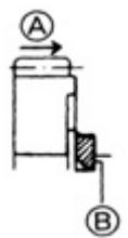
When placing an elastic ring, pay attention to its direction (place it towards the drag side).
The rounded face should be against the gears surface.
(A) Drag
(B) Sharp edge
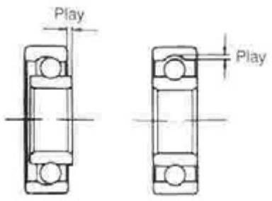
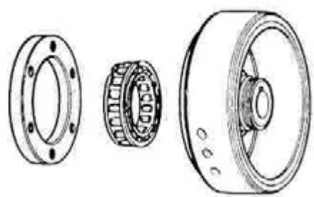
BEARINGS
- Wash the bearings with a solvent and lubricate them with engine oil before inspecting them.
Turn the interior guide ring and check if it turns easily. If it does not turn easily and without noise, or it presents signs of any anomaly, the bearing is defective and should be replaced by a new one in the following manner.
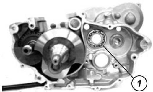
Gearbox primary axle right bearing
Remove the gearbox primary axle right bearing (1) with the special tool.
Tool ref.: Bearing extractor unit
WARNING Replace the extracted bearing with a new one.
Mount the gearbox primary axle right bearings with the special tool.
Tool ref.: Bearing mounting unit
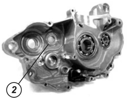
Gearbox primary axle left bearing
Remove the gearbox primary axle left bearing (2) with the special tool.
Tool ref.: bearing extractor
Tool ref.: percussion hammer
WARNING Replace the extracted bearing with a new one.
Mount the gearbox primary axle left bearing with the special tool.
Tool ref.: Bearing mounting unit
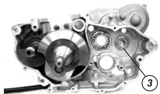
Gearbox secondary axle bearings
Remove the right bearings (3) and the left (4) of the gearbox secondary axle with the special tool.
Tool ref.:
Bearing extractor unit
WARNING
Replace the extracted bearings with new ones.
Mount the right and left bearings of the gearbox secondary axle with the special tool.
Tool ref.:
Bearing mounting unit
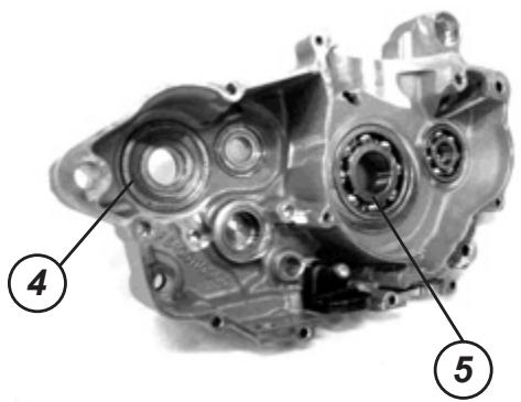
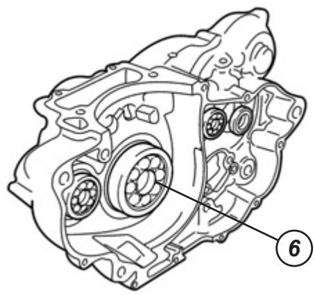
Crankshaft bearings
Remove the right bearings (5) and the left (6) of the crankshaft with the special tool.
Tool ref.:
Bearing extractor unit
WARNING
Replace the extracted bearings with new ones.
Mount the right and left bearings of the crankshaft with the special tool.
Tool ref.:
Bearing mounting unit
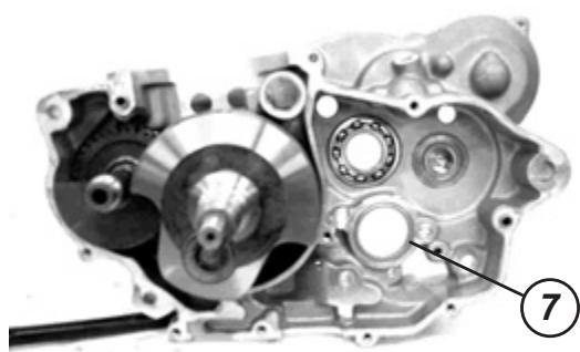
Desmodrome gearbox right bearing
Extract the desmodrome gearbox right bearing (7) with the special tool.
Tool ref.:
Bearing extractor unit
WARNING
Replace the extracted bearing with a new one.
Mount the right bearing of the desmodrome gearbox.
Tool ref.:
Bearings mounting unit
Desmodrome gearbox left bearing
Remove the desmodrome gearbox left bearing (8) with the special tool.
Tool ref.: Bearing extractor unit
WARNING Replace the extracted bearing with a new one.
Mount the left bearing of the desmodrome gearbox. Bearing extractor unit
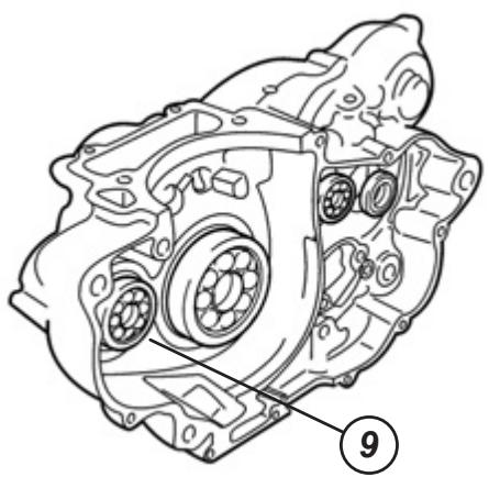
Balance axle right bearing
Extract the balance axle right bearing (9) with the special tool.
Tool ref.: Bearing extractor unit
WARNING Replace the extracted bearing with a new one.
Mount the balance axle right bearing.
Tool ref.: Bearing extractor unit
Tool ref.: Bearing mounting unit
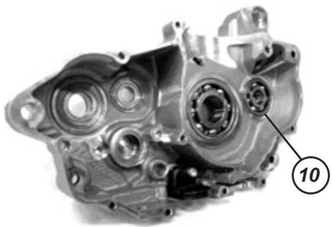
Balance axle left bearing
Extract the balance axle left bearing (10) with the special tool.
Tool ref.: Bearing extractor unit
WARNING Replace the extracted bearing with a new one.
Mount the balance axle left bearing.
Tool ref: Bearing mounting unit
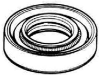
RETAINERS
If the lip of the retainers are deteriorated engine oil or gasoline/air mix leaks may be produced.
Check if the retainers are worn out or damaged. If you observe any imperfection, change the retainer with a new one.
Place the retainers in the sump and the clutch cover. Pay attention to the following points:
WARNING
Replace the extracted retainers with new ones.

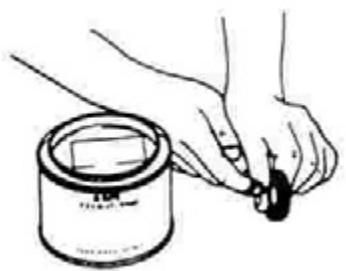
Apply grease to the retainer lips.
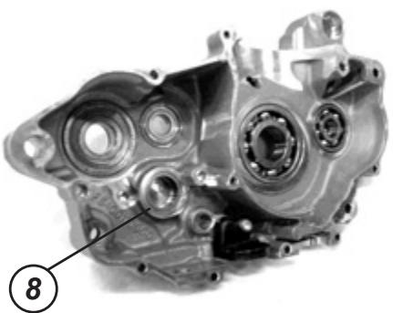
Gearbox secondary axle retainers
Remove the casing (1).
Remove the gearbox secondary axle retainer in the left sump (2) with the special tool.
Tool ref.:
Retainer extractor

WARNING
Replace the extracted retainer with a new one.
Slowly place the gearbox secondary axle retainer in the left sump with the special tool.
Tool ref.:
Retainer mounting unit

Selector axle retainer
Slowly remove the selector axle retainer of the left sump (1) with the special tool.
Tool ref.:
Retainer extractor
WARNING
Replace the extracted retainer with a new one.
Slowly place the selector axle retainer in the left sump with the special tool.
Tool ref.:
Retainer mounting unit
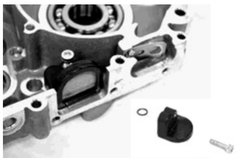
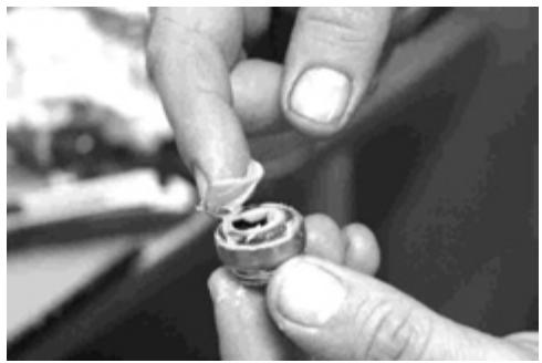
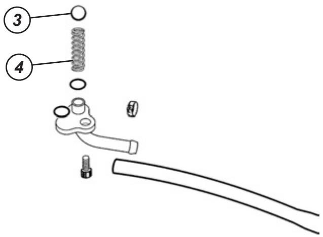
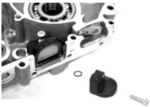
Oil retention valve
Remove the cover (2), the oil retention valve ball (3) and the spring (4) of the right sump.
To again mount the oil retention valve place the spring (4), the oil retention valve ball (3) and the cover (2) in the right sump.
Crankshaft cavity sheet and oil filter cleaning
Dismount the oil filter from the right sump interior.
Proceed to its cleaning without dismounting the filter sheet.
WARNING
If the filter is deteriorated, replace it with a new one.

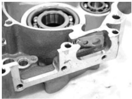
Dismount the crankshaft cavity sheet and check its completeness and good condition.
WARNING
If the crankshaft cavity sheet is deteriorated, replace it with a new one.

GASCAS
Periodic maintenance
Spark plug. 93
Oil filter and engine oil. 94
Engine oil tubes. 97
SPARK PLUG
Inspection after 30 hours of functioning. Replace after 60 hours of functioning.
Dismount the fuel tank.
Disconnect the spark plug pipe and remove the spark plug.
| COLD | STANDAR | HOT | |
| NGK | CR9E | CR8E | CR7E |
| DENSO | U27ESR-N | U24ESR-N | U22ESR-N |
U31ESR-N

Soot deposits
Check if there is soot in the spark plug.
If there is soot deposited, remove it using a wire prong brush.
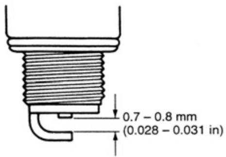
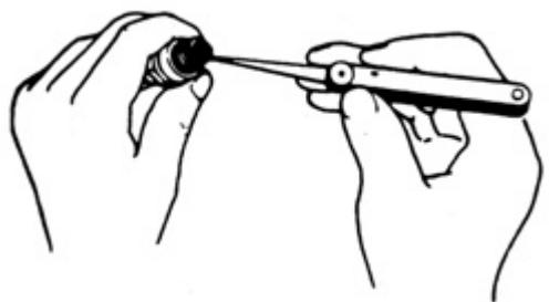
Spark plug tolerance
Measure the tolerance using a thickness gauge.
If the spark plug is out of tolerance, adjust the tolerance.
DATA:
Standard: Tolerance 0.7 - 0.8 mm
Tool:
Thickness gauge.
Electrode
Check the electrode status.
If the electrode is extremely worn out or burned replace the spark plug with a new one.
Also replace the spark plug if the isolator is broken, the thread damaged, etc.
WARNING
Check the shape and length of thread when replacing the spark plug. If the neck of the spark plug is too short, the soot will be deposited in the space of the glowplug and the engine may be damaged.

Installation of the spark plug
WARNING
To avoid damaging the thread of the first cylinder head screw the spark plug with the hand. Then tighten with the specified torque using the spark plug spanner.
Spark plug tightening torque:
11 Nm (1.1 Kgm, 8,0 Ib-ft).

OIL FILTER AND ENGINE OIL
Initially replace after 5 hours of use and then every 60 hours.
The oil should be changed while the engine is hot. The oil filter is changed in the same intervals of the engine oil.
Engine oil change
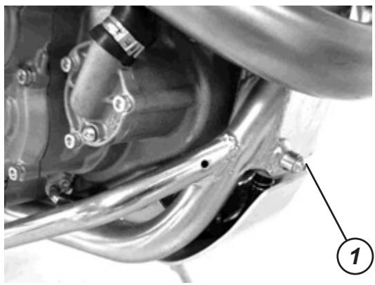
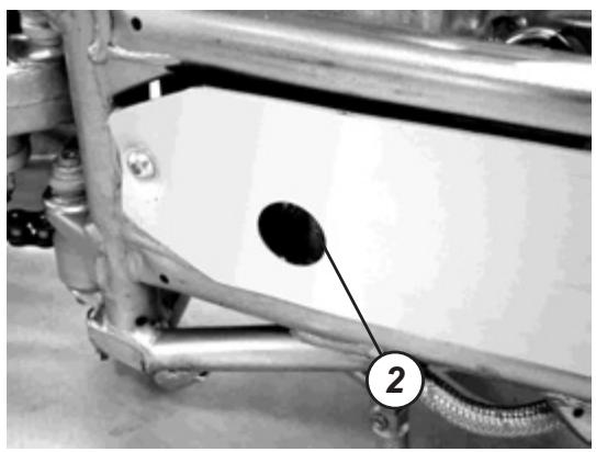
The engine oil is found in the tank of the chassis front high part and in the engine sump. To evacuate the oil open the chassis (1) and of the engine (2) plugs also the fill plug (3).
Once the oil comes out screw the screws with the specified torque and then fill the oil again through the fill hole. When performing an oil change (without replacing the oil filter), the engine will store about 1 L (1.05 US qt, 0.8 Imp qt) of oil. Use an engine oil that complies with the standard API classifications SF or SG and that it has a range of viscosity SAE 10W-40.
ENGINE OIL DRAINAGE
In sump (2): 21 Nm (2.1 Kg, 6.80 lb-ft)
In chassis (1): 18 Nm (1.8 Kg, 13.0 lb-ft)
WARNING
Screw the plug (1) take the precaution of placing the gasket correctly. If the gasket is damaged replace it with a new one.
To check the oil level place the motorcycle in the functioning position.
Screw the plug of the oil tank (3).
Place the motorcycle on and have three minutes at idle.
Stop the motorcycle and wait three minutes, check the oil level with the oil stick. The oil level should be between the level lines "L" and "F".
NOTE:
The oil extends and the same level increases when the engine oil is hot.
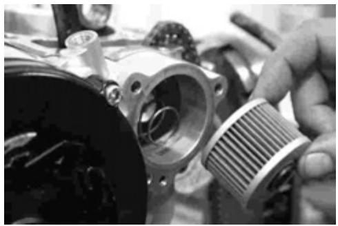
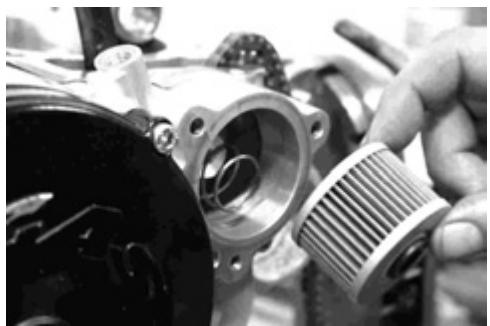
Oil filter change
Remove the oil filter cover (1) and the oil filter (2).
Change the filter with a new one.
NOTE:
Before mounting the filter cover make sure of the correct mounting of the spring and replace the filter cover gasket.
Makesure that the thoric behind the filter is placed in the correct position.
Change the oil filter cover and tighten the safety nut.
Add new oil to the engine and check the oil level just as described in the oil change procedure.
DATA:
Engine oil capacity
Change of oil: 1 L (1.05 US qt, 0.8 Imp qt)
Changing the oil and oil filter: 1.2 L (1.3 US qt, 1 Imp qt)
Engine check: 1.2 L (1.3 US qt, 1 Imp qt)
WARNING
Check the correct position of mounting of the filter (according to the images). If the filter is mounted in another position the engine may be damaged.
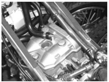
ENGINE OIL TUBES
Initial inspection after five hours of use and after 30 hours.
Check that the engine oil tubes are not damaged and that they have no leaks. If any damage is detected, change the tubes with new ones.
Check compression
The correct compression of a cylinder indicates that the internal conditions are good. The decision to inspect a cylinder is based on the results that we obtain when measuring the cylinder compression. Compression verification should be included in concessionaire inspections.
DATA Compression: Standard: 1000 Kpa (10.0 Kgf/cm2)

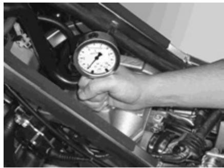
Compression testing procedure
NOTE: Before checking the engine compression, check that the cylinder head screws are tightened with the specific torque value and that the valves are correctly adjusted.
Warm up the engine before the test.
Check that the battery is totally charged.
Perform the compression measurement in the following manner:
- Remove the spark plug.
- Thread the pressure gauge in the cylinder head spark plug thread. Check that the connection is correct.
- Maintain the throttle valve in the totally open position.
- Press the ignition button and make the engine run for a few seconds.
- Note down the value of the maximum reading that the pressure gauge measures.
Tool ref.: Pressure gauge Adapter

Low compression may indicate some of the following conditions:
- Cylinder walls excessively worn out.
- Piston or segments worn out.
- Segments nailed to its seating.
- Valve seating in bad conditions.
- Rupture or other defects in the cylinder head.
NOTE: When the compression is low, check the engine for the conditions listed above.

Periodic maintenance
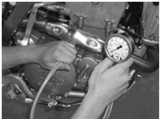
Oil pressure testing
Check the oil pressure periodically. This will give a good indication of the conditions of the engine moving parts.
DATA:
Oil pressure:
Above 40 Kpa (0.4 Kgf/cm2, 5.7 psi) at 3000 rpm
Above 140 Kpa (1.4 Kgf/cm2, 19.9 psi)
Oil pressure testing procedure
Connect tachometer to high voltage wire.
Remove the plug of the main oil circuit.
Warm up the engine as follows:
Summer: 10 minutes at 2000 rpm.
Winter 20 minutes at 2000 rpm.
After warming up the engine increase the speed to 3000 rpm (check with the tachometer) and read the oil pressure in the pressure gauge.
Tool ref.:
Pressure gauge
Adapter
Low or high pressure may indicate any of the following conditions:
Low oil pressure:
- Oil filter plugged.
- Leaks in the oil passages.
- Damaged thoric.
- Defective oil pump.
- Previous combinations.
High oil pressure:
- Engine oil of too high viscosity.
- Oil passages plugged.
- Previous combinations.

C/ Unicef, 17 - Poligon Industrial Torremirona - 1719 Salt (Girona) SPAIN
TEL +34 902 47 62 54 / FAX + 34 902 47 61 60
www.gasgasmotos.es