
ENDUCROSS EC - Off-road motorcycle GAS GAS - Free user manual and instructions
Find the device manual for free ENDUCROSS EC GAS GAS in PDF.

User questions about ENDUCROSS EC GAS GAS
0 question about this device. Answer the ones you know or ask your own.
Ask a new question about this device
Download the instructions for your Off-road motorcycle in PDF format for free! Find your manual ENDUCROSS EC - GAS GAS and take your electronic device back in hand. On this page are published all the documents necessary for the use of your device. ENDUCROSS EC by GAS GAS.
USER MANUAL ENDUCROSS EC GAS GAS
GAS GAS thanks you for the trust you have placed in us.
By choosing the new GAS GAS EC / MC / SM 2007 you have become part of the great GAS GAS family and, as a user of the number one manufacturer of off-road motorbikes, you deserve the distinguished treatment that we wish to offer to you both in our after-sale relationship and in the explanations that we provide in this manual.
Our EC / MC / SM 2007 is a motorcycle conceived for the practice of high-competition. It is actually the fruit of many years of competition and experimentation in this demanding discipline, as well as the many great successes achieved thanks to great trial riders who have contributed with their expertise to the basic data that have allowed us to create motorcycles of the highest level, GAS GAS unique motorcycles which count on important key factors: reliability, high features and a good stability.
Congratulations for making the right choice. With your skills at the command of this motorcycle, its adequate preparation and the corresponding indispensable servicing, this motorcycle will prove to be highly reliable, and you will be able to enjoy the most comfortable and rewarding practice of your favorite sport.
Thank you for your trust in us, and welcome to GAS GAS Motos, S.A.
July 2006
HOW TO USE THIS MANUAL
Read this Manual carefully. You will find it contains all the necessary information for your safety, and that of other persons, as well as guaranteeing the correct conservation and maintenance of the GAS GAS motorcycle that you have just acquired.
You will find all the necessary instructions for the correct riding and control of this vehicle are set out below. Each message is preceded by a symbol with the following meaning: .
WARNING
This warning symbol identifies special instructions or procedures which, if not correctly followed, could result in personal injury or even death.
CAUTION
This symbol identifies instructions or procedures which, if not followed strictly, could result in damage to or destruction of equipment.
NOTE
This note symbol indicates points of particular interest for more efficient and convenient operation.
Motorcycle riding, if improperly conducted, has the potential to cause environmental problems as well as conflicts with other people. Responsible riding use of your motorcycle will ensure that these problems and conflicts do not develop.
TO PROTECT THE FUTURE OF YOUR SPORT MAKE SURE YOU USE YOUR MOTORCYCLE WHITHIN THE LAW, SHOW CONCERN FOR THE ENVIRONMENT, AND RESPECT THE RIGHTS OF OTHER PEOPLE.
Motorcycle riding is a wonderful sport, and we hope you will enjoy it to the fullest.

RECOMMENDSTHEUSEOFOIL:

Global Racing Oil
TABLE OF CONTENTS
Foreword 3
How to use this manual 4
Table of contents. 5
Specifications 6
Location of components 8
Side Stand 12
Fuel 12
Serial Number 14
Homologation Plate. 14
Starting the engine 14
Shifting gears 15
Stopping the motorcycle 16
Riding during the Break-In Period 16
Maintenance Schedule 17
Electronic Ignition. 19
Cooling System 19
Spark Plug 20
Transmission 22
Air Cleaner 24
Throttle Cable 25
Carburetor 25
Clutch 26
Exhaust System 26
Drive Chain Guide 27
Handlebar 29
Brakes 30
Steering 31
Steering blockage 32
Front Fork 33
Rear suspension 36
Wheels 38
Cleaning. 39
Bolts and nuts tightening 40
Lubrication 42
Tunning (Carburetor and Suspension) 43
Final recommendations. .51
Homologation 52
Preparation for competition 53
Storage 54
GAS GAS Multifunction Instructions 55
Troubleshooting 61
Electric Schemas 66
Warranty Manual 67
SPECIFICATIONS
| ENGINE 125 cc Engine Bore and stroke Displacement | 2 cycles, single cylinder, crankcase intake, liquid cooled |
| 54 x 54.5 mm | |
| 124 cc | |
| 200 cc Engine (only EC) Bore and stroke Displacement | 62.5 x 65 mm |
| 199.4 cc | |
| 250 cc Engine Bore and stroke Displacement | 66.4 x 72 mm |
| 249.3 cc | |
| 300 cc Engine (only EC) Bore and stroke Displacement | 72 x 72 mm |
| 294.7 cc | |
| Carburettor, diameter of diffusor Lubrication system | 38 |
| Mixture | |
| 100% Synthetic Oil Mineral Oil (Only USA) | 50:1 = 2% 32:1 = 3% |
| Starting system | Starting lever |
| Ignition system | CDI system |
| Ignition timing | 1 mm BTDC |
TRANSMISSION
Transmission type
Clutch type
Secondary drive
Gear ratio (200 cc, 250 cc, 300 cc)
6 speed in cascade
Hydraulic operated multi-plate in oil bath
Chain driven
1st 2.071 (29/14)
2nd 1.625 (26/16)
3rd 1.333 (24/18)
4th 1.100 (22/20)
5th 0.913 (21/23)
6th 0.791 (19/24)
| Primary reduction | 2.85 (57/20) (250 cc, 300 cc) | |
| Final reduction | 3.692 (48/13) (250 cc, 300 cc) | |
| Overall gear ratio | 8.323 (6th gear) | |
| Transmission oil | Capacity | 750 cc (125 cc) |
| 900 cc (200 cc / 250 cc / 300 cc) | ||
| Type | 10W30 API SF or SG |
| CHASSIS | ||
| Type | Tubular, semi-double cradle | |
| Tire size | Front | EC & MC - 90/90 x 21 |
| SM - 120/60 ZR17 | ||
| Rear | EC - 140/80 x 18 | |
| MC - 120/80 x 19 | ||
| SM - 150/60 ZR17 | ||
| Suspension | Front | Inverted telescopic fork Ø 45 mm (only EC, SM and MC 125) |
| Inverted telescopic fork Ø 50 mm (only MC 250) | ||
| Rear | Progressive system with single multi-adjustable shock | |
| Suspension stroke | Front | 282 mm |
| Rear | 320 mm | |
| Front fork oil | SAE 5 - 7.5 | |
| Front fork oil level | 110 mm (compressed, without spring) | |
| BRAKES | ||
| Type | Front, Rear | Disc brake |
| Effective disc diameter | Front | 260 mm (only EC and MC) |
| 320 mm (only SM) | ||
| Rear | 220 mm | |
| DIMENSIONES | |
| Overall height | 1260 mm |
| Overall length | 2135 mm |
| Overall width | 810 mm |
| Seat height | 940 mm |
| Minimum height | 340 mm |
| Wheelbase | 1475 mm |
| Fuel tank capacity | 9 l |
(Specifications are subject to change without notice and probably do not apply to all countries).
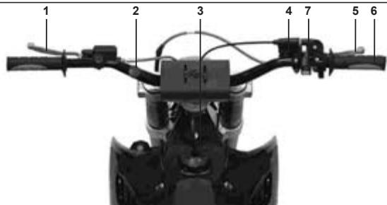
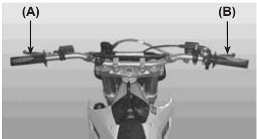
1- Clutch lever
2- Steering and lighting controls
3-Fuel tank cap
4- Brake fluid reservoir
5- Front brake lever
6-Throttle grip
7- CDI Switch
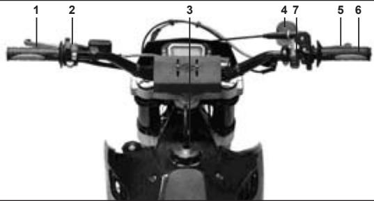
GAS GAS MC 2007
1- Clutch lever
2- Engine stop button
3-Fuel tank cap
4- Brake fluid reservoir
5-Front brake lever
6-Throttle grip
7- CDI Switch
GAS GAS SM 2007
1- Clutch lever
2- Steering and lighting controls
3-Fuel tank cap
4- Brake fluid reservoir
5-Front brake lever
6-Throttle grip
7- CDI Switch
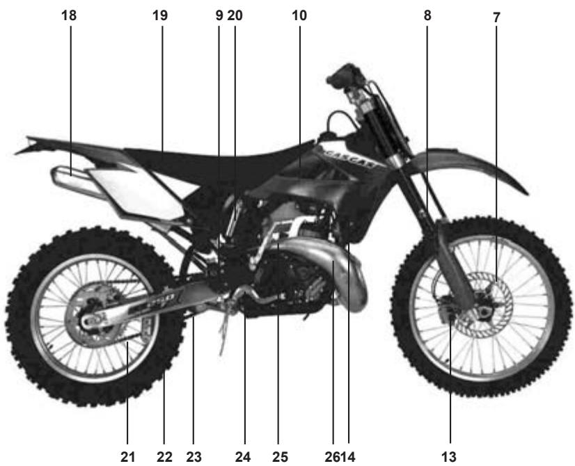
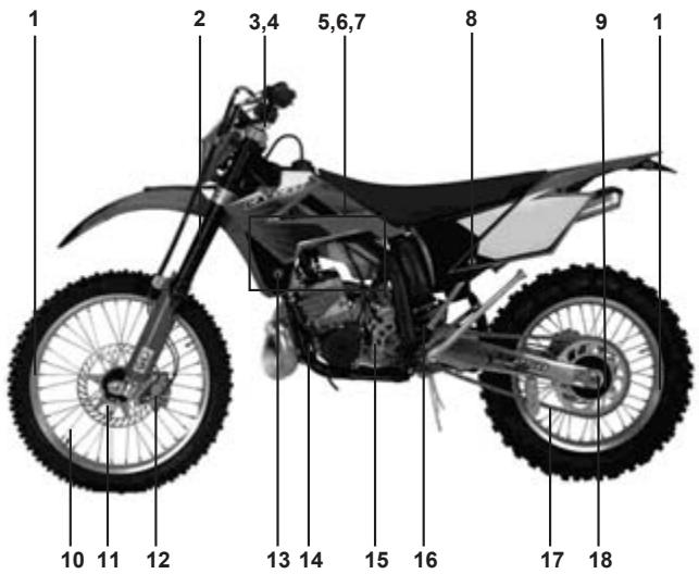
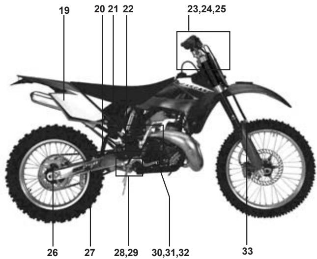
GAS GAS EC 2007
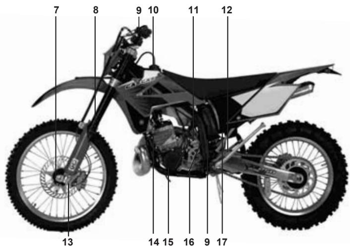
7- Brake disc
8- Front suspension
9- Brake fluid reservoir
10-Fuel tank
11-Carburetor
12-Rear shock absorber
13- Brake caliper
14-Radiator
15-Gasoline cock
16-Shift pedal
17-Air cleaner
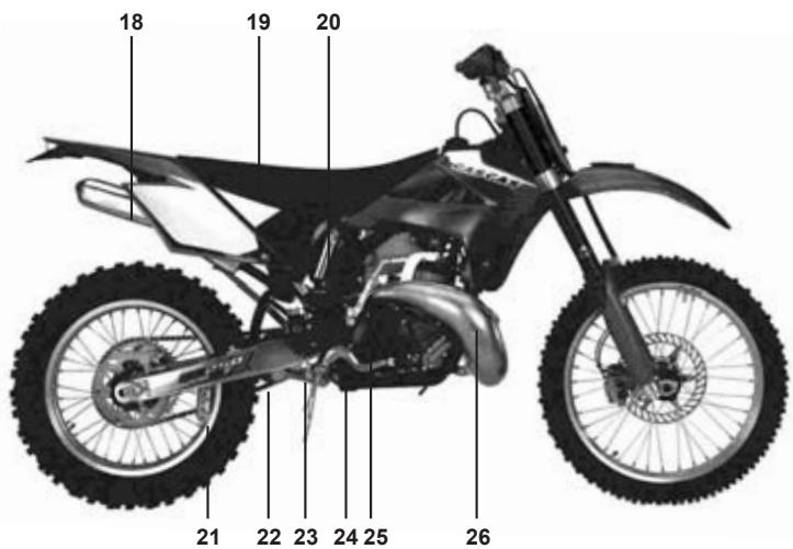
18-Muffler
19-Seat
20-Gas reservoir
21-Chain guide
22-Chain
23- Suspension linkage and swingarm
24- Rear brake pedal
25- Kick-start pedal
26- Exhaust
GAS GAS MC 2007
7- Brake disc
8- Front suspension
9- Brake fluid reservoir
10-Fuel tank
13- Brake caliper
14-Radiator
18-Muffler
19-Seat
20-Gas reservoir & Rear shock absorber
21-Chain guide
22-Chain
23- Suspension linkage and swingarm
24- Rear brake pedal
25- Kick-start pedal
26- Exhaust
GAS GAS SM 2007
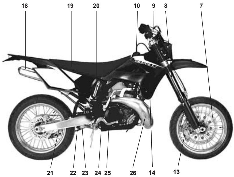
7- Brake disc
8- Front suspension
9- Brake fluid reservoir
10-Fuel tank
14-Radiator
18-Muffler
19-Seat
20-Gas reservoir & Rear shock absorber
21-Chain guide
22-Chain
23- Suspension linkage and swingarm
24- Rear brake pedal
25-Kick-start pedal
26- Exhaust
SIDE STAND (only EC and SM)
To set the side stand only turn it until it contacts the stopper, then the side stand will be parallel to the ground and rest securely.
The side stand will return to its original position by means of the double spring. The function of the double spring insures that, when the side stand is down, the rest position is stable and above all secure; moreover, it also returns the side stand to its original position.
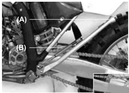
EC 2007 and SM 2007
(A). Side stand.
(B). Double spring.
MC 2007
(A). Side stand.

NOTE
Do not start the engine or ride the motorcycle when the side stand is down.
FUEL
The GAS GAS EC / MC / SM models have 2-cycle engines that require a mixture of gasoline and oil.
| Gas Tank Capacity |
| 9 L |
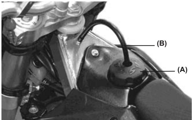
(A). Fuel tank cap.
(B). Vapor outlet tube.
The fuel tank cap is of the quick-release type.
To open the fuel tank cap, lift the plated latch and turn cap counterclockwise.
To close it, turn the cap clockwise and lower the latch.
NOTE
It is recommended that the rubber seal should be checked thoroughly to insure it is airtight.
RECOMMENDED FUEL
Use gasoline with an octane rating equal to or higher than that shown in the table.
| OCTANE RATING METHOD | MINIUMRATING |
| Antiknock Index (RON+MON)/2 | 90 |
| Research Octane No. (RON) | 98 |
NOTE
If knocking or pinging occurs, try a different brand of gasoline or higher octane grade.
| WARNING |
| Gasoline is extremely flammable and can be explosive under certain conditions. Always stop the engine and do not smoke. Make sure the area is well ventilated and free from any source of flame or sparks; this includes any appliance with a pilot light. |
Mixing oil inside the engine
Oil must be mixed with gasoline to lubricate the piston, cylinder, crankshaft, and connecting rod bearings.
Recommended oil: CYCLE SYNTHETI
NOTE
If the recommended oil is not available, use only oil designed for racing with 2-cycle engines.
Gasoline and engine oil mixing proportions:
Synthetic oil 100% : gasoline 50, engine oil 1 = 2% Semi-synthetic oil: gasoline 50, engine oil 1 = 2% Mineral oil: gasoline 32, engine oil 1 = 3%
| CAUTION |
| Do not mix vegetable and mineral based oils. |
| Too much oil will cause excessive smoking and spark plug fouling. |
| Too little oil will cause engine damage or premature wear. |
| CAUTION |
| Below 0 °C do not use 100% synthetic oil. |
To prepare the mixture, first pour oil and half of the gasoline used into a container and stir the mixture thoroughly. Then add the rest of the gasoline and stir the mixture well.
NOTE
At low temperature, oil will not easily mix with gasoline. Take time to ensure a well-blended mixture. The lubrication quality of this mixture deteriorates rapidly; use a fresh mixture for each day of operation.
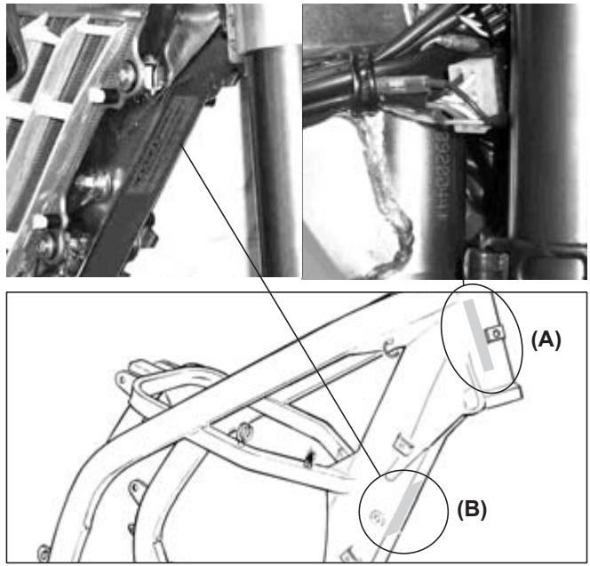
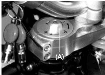
SERIAL NUMBER (A)
It is stamped on the steering pipe. It indicates the frame number registered for this motorcycle.
HOMOLOGATION PLATE (B)
This motorcycle carries its corresponding homologation plate where it also shows the serial number, and this data must match the information registered in the motorcycle documents.
STARTING THE ENGINE
- Make sure the motorcycle is in the neutral position.
- Turn the gasoline cock (A) clockwise to the "ON" position.
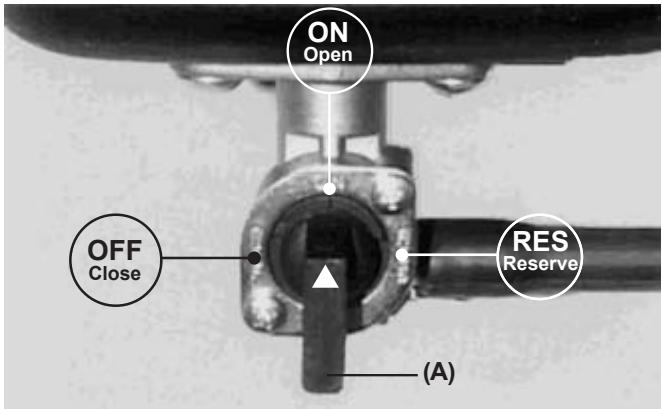
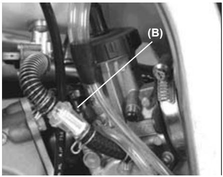
3. If the engine is cold, pull up the choke knob (B).
NOTE
- When the engine is already warm or on hot days, open the throttle instead of using the choke knob.
- If the engine is flooded, kick with the throttle fully open.
- If the clutch lever is pulled, the motorcycle can be started while in any gear.
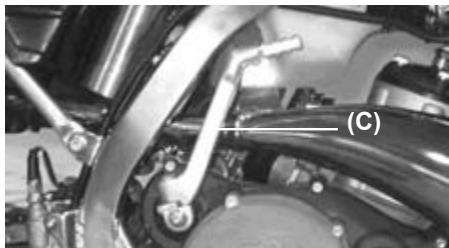
-
Start the motorcycle with kick-start pedal (C).
-
Even after the engine starts, keep the choke knob pulled up.
Stopping the engine (EC and SM models)
- Shift the transmission into neutral.
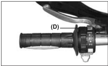
-
After racing the engine slightly, close the throttle completely and depress the engine stop button (D).
-
Turn the key in counterclockwise direction to the "OFF" position.
Stopping the engine (MC model)
-
Shift the transmission into neutral.
-
After racing the engine slightly, close the throttle completely and depress the engine stop button (A).
SHIFTINGGEARS
The transmission is a 6-speed, of the return shift type. A return shift means that to go from first gear to third gear it must go first through the second gear, that is to say that it upshifts gears one by one. To engage first gear from neutral, pull the clutch lever in and push down on the gearshift pedal, then release the gearshift pedal and gently release the clutch lever.
CAUTION
When shifting gears, press firmly on the gearshift pedal to ensure a positive shifting. Careless, incomplete shifts can cause the transmission to jump out of gear and cause engine damage.
(A)
(A). Gearshift pedal.
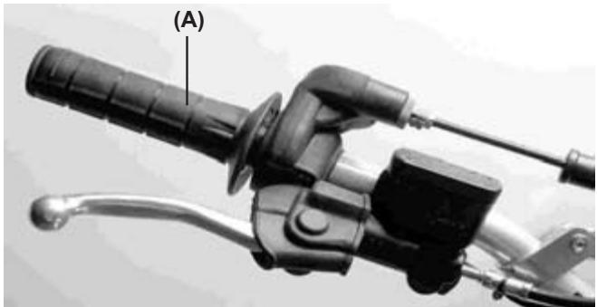
STOPPING THE MOTORCYCLE
For maximum deceleration, close the throttle (A) and apply both front and rear brakes. Disengage the clutch as the motorcycle comes to a stop. Independent use of the front or rear brake may be advantageous under certain conditions.
Downshift progressively as speed is reduced to ensure good engine response when you want to accelerate.
RIDING DURING THE BREAK-IN PERIOD
A break-in period is necessary to ensure a smooth operation and obtain an optimum engine and the transmission responses. During the first hour or 20km of operation, run the engine at low and moderate speeds and revolutions per minute (RPM).
NOTE
The slow riding necessary during the break-in period may cause carbon deposits to build up on the spark plug and foul it. If inspection of the spark plug shows this to be the case, replace the standard spark plug with another of a higher heat range.
Perform the break-in period following these steps:
- Start the engine and let it run at idle until the engine is warm.
- Stop and let the engine cool completely.
- Start the engine and ride for 10 minutes at moderate speed - NEVER ACCELERATE HARD.
- Stop and let the engine cool completely. Be sure to check and adjust chain slack and spoke tightness and cxarry out a general inspection.
- Start the engine and ride for 20 minutes at moderate speed. - NEVER ACCELERATE HARD.
- Stop and let the engine cool completely. Check and adjust as needed (Refer to the table of adjustments).
- Install the parts removed.
- Fill the radiator with the recommended coolant. Before starting the motorcycle, bleed the air from the cooling system.
- Start the engine and ride for 30 minutes at moderate speed.
- Stop and let the engine cool completely. Check and adjust.
- After the break-in procedure has been properly carried out, the motorcycle is ready for regular operation.
CAUTION
However, avoid accelerating recklessly that can lead to engine failure. Be careful to use the necessary skills and techniques while operating the motorcycle.
NOTE
After the break-in period, install a new set of standard spark plugs.
| MANTENANCE SCHEDULE | |||||
| Item | Check / Inspect | Adjust | Change / Replace | Clean | Apply grease / Lubricate |
| Clutch | At each fill up | At each fill up | At each fill up* | - | At each fill up |
| Discs | 3 fill ups | 3 fill ups* | 3 fill ups* | - | - |
| Throttle cable | - | 1 fill up | - | - | - |
| Spark plug | - | - | - | 1 fill up | - |
| Air cleaner element | - | - | When damaged | 1 fill up | - |
| Carburetor | 1 fill up | 1 fill up | - | - | - |
| Transmission oil | - | - | 3 fill ups | - | - |
| Piston and piston ring | 3 fill ups | 3 fill ups* | 3 fill ups* | 3 fill ups | - |
| Cylinder head, cyl. & exhaust valves | 3 fill ups | 3 fill ups* | 3 fill ups* | - | - |
| Exhaust | 1 fill up | 1 fill up* | 1 fill up* | 1 fill up | - |
| Muffler gasket | - | 10 fill ups* | 10 fill ups | - | - |
| Piston bearing | 3 fill ups | 3 fill ups* | 10 fill ups | - | 3 fill ups |
| Kick-start pedal and gearshift pedal | - | - | - | - | 1 fill up |
| Exhaust pipe o'ring | - | - | 3 fill ups | - | - |
| Engine bearings | 10 fill ups | 10 fill ups* | 10 fill ups* | - | - |
| Coolant | 3 fill ups | 3 fill ups* | 3 fill ups* | - | - |
| Radiator tube and connections | 1 fill up | 1 fill up* | 1 fill up* | - | - |
| Brake adjustment | 3 fill ups | 3 fill ups* | 3 fill ups* | - | - |
| Brake pads wear | 5 fill ups | 5 fill ups* | 5 fill ups* | - | - |
| Brake fluid level | 3 fill ups | 3 fill ups* | 3 fill ups* | - | - |
| Brake fluid | - | - | Every 2 years | - | - |
| Brake pump piston & dust cover | - | - | Every 2 years | - | - |
The maintenance and adjustments in this table are easy to follow and must be carried out to keep the motorcycle in good running condition.
NOTE: (*) Inspect and carry out these operations only if it is necessary.
| MANTENANCE SCHEDULE | |||||
| Item | Check / Inspect | Adjust | Change / Replace | Clean | Apply grease / Lubricate |
| Brake caliper piston seal & dust seal | - | - | Every 2 years | - | - |
| Brake hose and pipe | - | - | Every 4 years | - | - |
| Spoke tightness and rim runout | 1 fill up | 1 fill up* | 1 fill up* | - | - |
| Lubricate drive chain | - | - | - | - | 1 fill up |
| Drive chain | 1 fill up | - | - | - | - |
| Drive chain wear | - | 5 fill ups | 5 fill ups | - | - |
| Chain slider | 5 fill ups | 5 fill ups* | 5 fill ups* | - | - |
| Front fork | 1 fill up | When necessary | When damaged | When necessary | - |
| Front fork oil | - | - | Every year | - | - |
| Nuts, bolt, fasteners | 5 fill ups | 5 fill ups* | 5 fill ups* | - | - |
| Fuel hose | 7 fill ups | 7 fill ups* | 7 fill ups | - | - |
| Fuel system | - | - | 10 fill ups | When necessary | - |
| Steering play | 1 fill up | - | - | - | - |
| Rear sprocket | 5 fill ups | 5 fill ups* | 5 fill ups* | - | - |
| General lubrication | 5 fill ups | - | - | - | 5 fill ups |
| Steering bearing | - | - | - | - | 10 fill ups |
| Wheel bearing | 10 fill ups | 10 fill ups* | 10 fill ups* | - | - |
| Swingarm and linkages | 5 fill ups | 5 fill ups* | 5 fill ups* | - | 5 fill ups |
| Rear shock absorber oil | Every 2 years | 2 years* | 2 years* | - | - |
The maintenance and adjustments in this table are easy to follow and must be carried out to keep the motorcycle in good running condition.
NOTE: (*) Inspect and carry out these operations only if it is necessary.
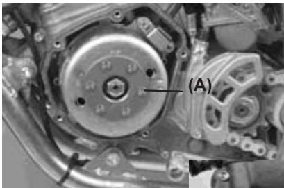
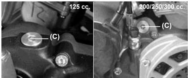
ELECTRONIC IGNITION
This motorcycle uses a capacitor discharge ignition system (CDI). The ignition system should never require adjustment unless the stator of the magnetic flywheel was incorrectly installed during engine reassembly.
If necessary, inspect and adjust as follows:
Adjustment
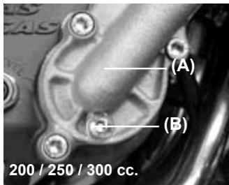
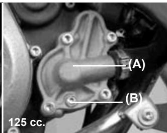
- Remove the magnetic flywheel cover (A).
- Make sure that the mark on the stator plate is aligned with the mark on the crankcase.
125cc
200/250/300cc
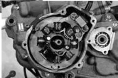
- If the marks are not aligned, loosen the magnetic inertia wheel screws and turn it.
- Tighten the screws securely.
- Install the magnetic flywheel cover.
NOTE
Engine tune-up can be adjusted to match the rider's preferences and skills.
- Remove the magnetic flywheel cover.
- Loosen the stator screws.
- Adjust the engine tune-up by changing the position of the stator within prudent limits
NOTE
For the best engine performance, it is very important to adjust the engine tune-up within the set of limits described.
- Tighten the stator screws.
- Install the magnetic flywheel cover.
- Test ride the motorcycle and readjust the engine tune-up, if necessary.
COOLING SYSTEM
Radiator Hoses
Check the radiator hoses for cuts or deterioration, and the connections for looseness and leaks.
Radiator
Check the radiator fins for obstructions (insects or mud). Remove any obstructions with a stream of low water pressure.
| CAUTION |
| If high water pressure is used the radiator fins could be damaged and impair the radiator effectiveness. Do not obstruct or deflect airflow through the radiator by installing unauthorized accessories. Any interference with the radiator airflow can lead to engine overheating and damage. |
Coolant information
To protect the cooling system aluminum parts (engine and radiator) from rust and corrosion, the use of corrosion and rust inhibitors chemicals in the coolant is essential. If rust inhibitors were not used, over a period of time the radiator will be corroded. This will clog the tubes of the cooling system.
| CAUTION |
| Use of incorrect coolant solutions will cause engine and cooling system damage. |
| Use coolant containing corrosion inhibitors made specifically for aluminum engines and radiators in accordance with the instructions of the manufacturer. |
| WARNING |
| Chemical liquids are harmful to the human body. Follow manufacturer instructions. |
| CAUTION |
| Distilled water must be used with corrosion inhibitors and the antifreeze in the cooling system. If tap water is used in the system, the cooling tubes can be clogged and reduce the cooling system efficiency. |
If the lowest ambient temperature encountered falls below the freezing point of water, protect the cooling system. Use a permanent type of antifreeze in the cooling system (distilled water and ethylene glycol and corrosion inhibitors for aluminium engines and radiators).
For the coolant mixture ratio under extreme conditions, choose the mixture ratio listed on the container for the lowest ambient temperature.
| CAUTION |
| Permanent types of antifreeze have anticorrosion and anti-rust properties. When it is diluted excessively, it loses its antifreeze and anticorrosion properties. Mix in accordance with the instructions of manufacturer. |
Liquid recommended
Permanent type of antifreeze (distilled water and ethylene glycol) plus corrosion inhibitors for aluminium engines and radiators.
NOTE Initially, at the factory a permanent type of antifreeze is installed in the cooling system. It is colored green, it contains a 50% solution of ethylene glycol, and has a freezing point of -35^.
Coolant recommended
Coolant absorbs excessive heat from the engine and transfers it to the air at the radiator. If the coolant level is low, the engine overheats and may suffer severe damage. Check the coolant level each day before riding the motorcycle. Add liquid recommended if the level is low (see next page).
WARNING
To prevent severe scalding do not remove the radiator cap or try to change liquid, when the engine is still hot. Wait until it cools.
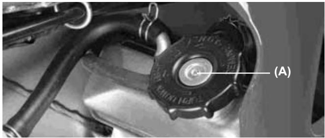
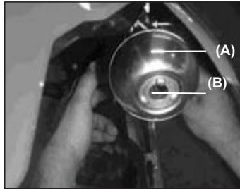
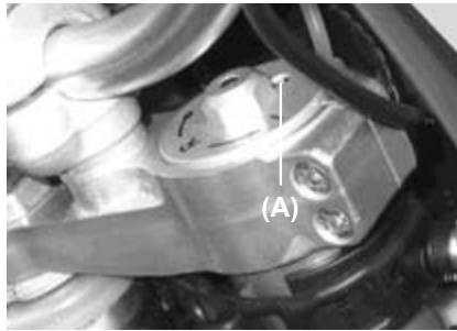
Coolant level
- Place the motorcycle in riding position.
- Turn the radiator cap (A) counterclockwise and wait a few seconds until vapors inside are released. Then push and turn it further in the same direction and remove the cap.
NOTE
Check the level when the engine is cold.
- Check the coolant level. The coolant level should be just at a level below de cap rubber seal.
- If the coolant level is low, add the correct amount of coolant through the filler opening.
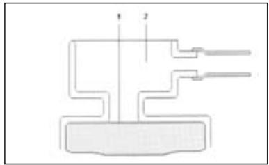
(1). Coolant level.
(2). Filler opening.
Total quantity
Mix antifreeze and distilled water 1:1 (distilled water 50% , antifreeze 50% ).
Capacity: 1.1 L
Coolant Replacement
Coolant should be changed periodically to ensure long engine life.
- Wait for the engine to cool completely.
- Place the motorcycle in riding position.
- Remove the radiator cap.
- Place a container under the coolant drain screw, and drain the coolant from the radiator and engine by removing the drain screw (B) at the bottom of the water pump cover (A). Wash off immediately any coolant spilled on the chassis, engine, or wheels.
WARNING
If coolant gets on the tires will make them very slippery and can cause an accident.
- Visually inspect the old coolant. If whitish spots are observed in the liquid is a clear indication that the aluminum parts in the cooling system are corroded. If the coolant is brown, iron or steel parts of the system are rusting. In both cases, flush the cooling system.
- Check the cooling system for damage, leaks or missing gaskets in the cooling system.
- Install the water pump cover drain screw with the specified torque values shown in the table. Always replace the gasket with a new one.
Drain plug tightening torque (refer to torque table) Water pump screw: 9 Nm
- Fill the radiator up to the edge of the cap with coolant, and install the radiator cap.
- Inspoect the cooling system for leaks.
- Start and warm up the engine, then stop the engine.
- Check the coolant level after the engine cools down. Add coolant up to the cap.
SPARK PLUG
The standard spark plug is a shown in the table and should be tightened to 27 Nm.
Standard Spark Plug
125cc
0.7-0.8 mm
200/250/300cc
0.7-0.8 mm
The spark plug should be removed periodically to check its gap. If the plug is oily or has carbon deposits, clean it with a sandblaster. After removing the abrasive particles, the spark plug must be cleaned using a wire brush or a similar tool. Measure the gap with a feeler gauge, if incorrect adjust the gap by bending the side electrode. If the spark plug electrodes are corroded or damaged, or if insulator is cracked, replace the plug.
NOTE
Inspect every 30 hours and change every 60 hours.
To find out whether the right heat range plug is being used, remove it and inspect the ceramic insulator around the center electrode. If the ceramic is light brown, the spark plug is correctly matched to engine temperature. If the ceramic is whie, the spark plug should be replaced with the next colder plug. If the ceramic is black, the spark plug should be replaced with the next hotter plug.
NOTE
If the engine performance drops, replace the spark plug first to recover its output.
TRANSMISSION
For the transmission and clutch to function properly, maintain the transmission oil level at the optimum level and change it periodically. A motorcycle with insufficient transmission oil, deteriorated or contaminated can accelerate wear and tear and cause transmission damages.
Oil level inspection
- Wait a few minutes if the motorcycle has been operating.
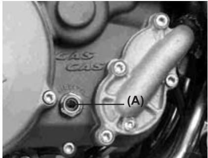
- Check the oil level through the inspection window in the lower right hand side of the engine (A).
Oil level must be kept between the maximum and minimum marks.
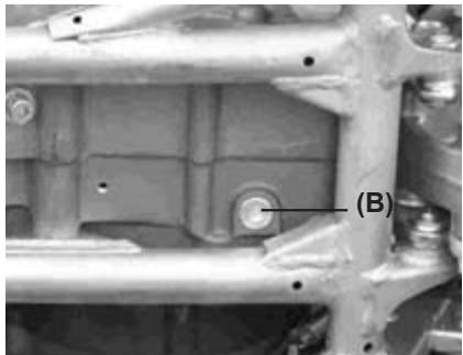
-
If the lever is too high, you have to remove the excess oil through the drain plug (B).
-
If the level is low, add the necessary quantity of oil by opening the plug (C). Use the same type and oil manufacturer used currently with the engine.
Transmission Oil
Viscosity: SAE 10W30
Capacity: 750 cc (EC 125)
900 cc (EC 200-250-300)
Oil change
NOTE
The engine must be completely cool and then warm up the engine again for a few minutes to normal operating temperature, to register the correct engine oil temperature and to obtain an accurate oil level measurement.
- The transmission oil should be changed periodically to ensure long engine life.
- Warm up the engine for 5 minutes so any oil sediment will float.
- Stop the engine, and place an oil pan under the engine.
- Remove the drain screw (see previous photo) and place the motorcycle in riding position to allow the oil to drain out.
- Clean the drain screw magnet of any iron particles.
- Tighten the oil drain screw with its O-ring to 20-Nm.
- Remove the oil filler opening plug (C) and pour 900 cc of new transmission oil for the models 200 / 250 / 300, and 750 cc for model 125.
- Check the oil level, after kicking the kick-start pedal 3 or 4 times.
Install the oil filler opening plug.
AIR CLEANER
A clogged air cleaner restricts the engine air intake, increasing fuel consumption, reducing engine power, and causing spark plug fouling.
WARNING
A clogged air cleaner may allow dirt and dust to enter the carburetor and stick the throttle open. This could cause an accident.
CAUTION
A clogged air cleaner may allow dirt and dust to enter the engine causing excessive wear and tear and other damages.
Do not omit checking the element, before and after each race or practice session. Clean it if necessary.
Element Cleaning
WARNING
Clean the element in a well-ventilated area, and make sure that there are no sparks or flame anywhere near the working area (this includes any appliance with a pilot light). Do not use gasoline to clean the element because could cause an explosion.
- Remove the cover.
-
Remove the screw (A) and remove the filter (B).
-
Place a lint-free towel in the intake port of the carburetor so no dirt is allowed to enter the carburetor.
CAUTION
Do not turn the filter since it can be easily damaged or torn.
- Wipe out inside the air cleaner hoousing with a clean damp towel.

-
Pull the cage (B) out of the air cleaner (A).
-
Clean the filter using a soft bristle brush in a bath of filter cleaning fluid.

-
Squeeze it dry with a clean towel. Do not wring the element or blow it dry since it can be damaged.
-
Inspect the filter for damage such as tears, hardening, or shrinkage. If damaged, replace it or it will allow dirt into the carburetor.
- Apply grease to all connections and screws in the air cleaner and intake ports.
Install the filter in the cage and pack the filter lip with grease (A), to ensure good sealing and prevent dirt entrance.
Install the seat.
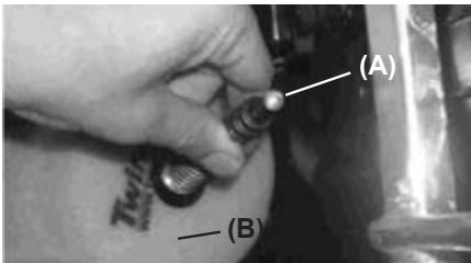
THROTLE CABLE
- Check that the throttle grip turns smoothly.
- Check that the throttle grip has 2-3 mm of free play.
- If the free play is incorrect, loosen the locknut on the upper end of the throttle cable, and turn the adjuster to obtain the correct amount of free play.
- Tighten the locknut again.
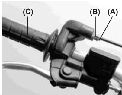
(A). Adjuster.
(B). Locknut.
(C). Throttle grip.
- If the free play cannot be set by adjusting the cable, remove the cable protector in the throttle body. Make the necessary free play adjustments with the tensor at the end of the cable, tighten the locknut, and reinstall the protector.
CARBURETOR
Idle speed adjustment
Is carried out using the air screw (A) and idle screw (B).
- First turn in the air screw until it is loose, then tighten it 1 1/2 turns.
- After thoroughly warming up the engine, turn the idle adjusting screw to obtain the desired idle speed. If there are no idle preferences, turn the screw until the engine stops.
- Tighten lightly the idle screw.

(A). Air screw.
(B). Idle screw.
- Open and close the throttle a few times to make sure the idle speed does not change. Readjust if necessary.
- With the engine idling, turn the handlebar to each side. If handlebar movement changes the idle speed, the throttle cable may be improperly adjusted or routed incorrectly, or it may be damaged. Be sure to correct any of these conditions before riding.
WARNING
Riding with a damaged throttle cable could be dangerous.
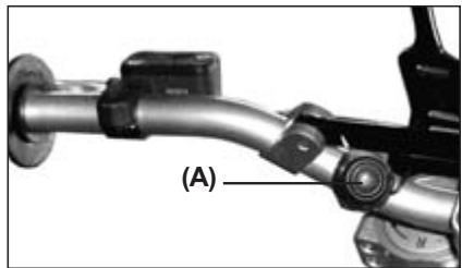
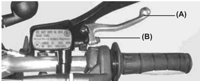
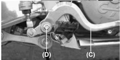
CLUTCH
The clutch lever should have a maximum play of 3mm . This margin increases with the wear on the clutch plate.
To adjust, proceed as follows:
- Use bolt A to adjust the lever's range of movement to the rider's convenience.
- Adjust the play of the lever using bolt B.
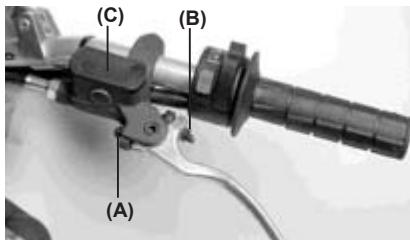
WARNING
- Maintain the clutch lever with the play shown, otherwise the performance and useful life of the clutch may be adversely affected.
- The EC 2006 model uses mineral oil GRO ULTRA 5 for the clutch hydraulic circuit.
- Tank C must not be filled with liquid from the models of previous years.
EXHAUST SYSTEM
The exhaust and the muffler reduce the noise and send gases away from the rider.
If the exhaust is badly damaged, dented, cracked or rusted, replace it with a new one. Replace the muffler fibre if the exhaust noise becomes too loud or if the engine performance drops.
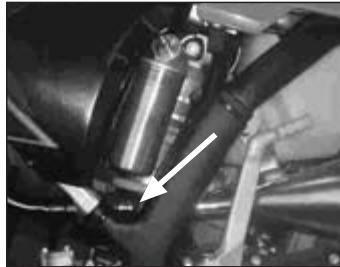
Muffler replacement
- Remove the retaining screws of the right side number-posting cover.
- Remove the retaining screws (A) of the muffler (B) and remove the muffler towards the rear.
- Separate the silencer from the joint -arrow-.
-
Replace the muffler and reinstall the assembly.
-
Remove all cover rivets with a drill.
- Remove the inside core of the muffler.
- Replace the muffler fibre by wrapping it around the inner tube.
- Reinstall the assembly.
(A). Rivets.
(B). Cover.
(A)
(B)
125/200cc.
m = 311
4
1
②
m = 311 ;
1
A
250/300cc
DRIVE CHAIN GUIDE
The drive chain must be checked, adjusted, and lubricated in accordance with the Maintenance Schedule. If the chain is worn or adjusted incorrectly (either too loose or too tight) the chain could become loose or break. Replace the chain, if necessary.
WARNING
A chain that breaks or becomes loose could snag on the engine or on the rear wheel, severely damaging the motorcycle and causing it to go out of control
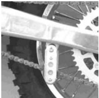
EC Model
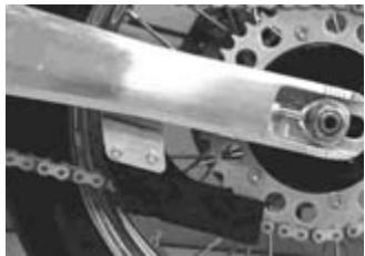
MC and SM Models
Drive Chain Slack Inspection
The space between the chain and the swingarm at the same height of the chain slider should be 30 - 50mm . Rotate the rear wheel to find the place where the chain is tighter. Adjust the drive chain if it has too much or too little slack.
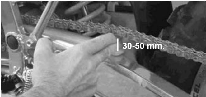
In addition to checking the slack, rotate the rear wheel to inspect for damaged rollers, loose pin and links, unevenly or excessively worn teet, and damaged teeth.
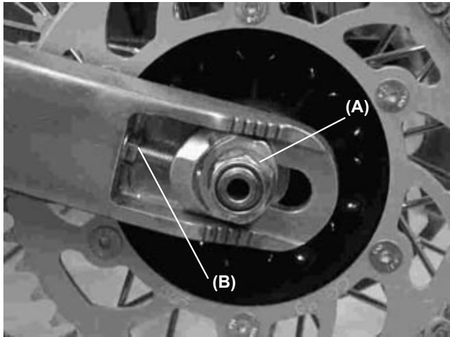
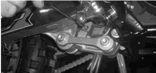
Drive Chain Slack Adjustment
- Loosen the rear axle nut (A).
- Turn the nuts on the chain adjusting tensors (B) until the drive chain has a gap of 30 - 50mm between the chain and the swing arm. To keep the chain and wheel aligned, the left chain tensor should aligned with the right chain tensor.
WARNING
Misalignment of the wheel will result in abnormal wear and may cause an unsafe riding condition.
NOTE
Wheel alignment can also be checked using the string metod.
- Tighten the chain tensor nuts (B).
- Tighten rear axle nut to 98 Nm.
- Rotate the wheel, measure the chain slack again at the tightest position, and readjust if necessary.
WARNING
If the axle nut is not securely tightened an unsafe riding condition may result.
Drive chain, chain guide, chain slider, and rear sprocket teeth.
When the chain is worn so much that it is more than 2% longer than when new, it is no longer safe for use and should be replaced. Whenever the chain is replaced, inspect both the engine output pinion and rear sprocket teeth, and replace them if necessary. Worn sprocket teeth will cause a new chain to wear quickly.
NOTE
When a part ir worn, replace it with a genuine part for maximum resistance and safety.
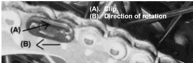
To minimize any chance of the master link coming apart, the master link clip must be installed with the closed end of the «U» facing in the direction of the chain rotation.
Chain Guide Slider
Visually inspect the upper and lower chain slider at the location of the swingarm. If damaged or worn, replace it with a new part.
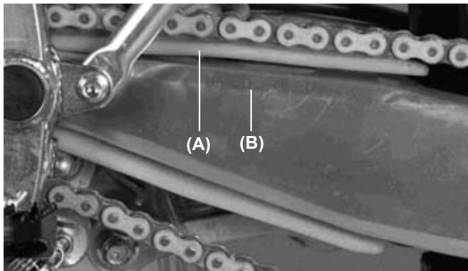
(A). Chain Guide Slider.
(B). Swingarm.
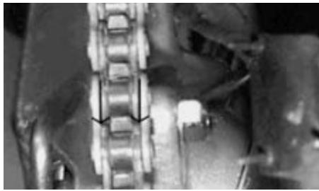
Pinion Teeth, Pinion Sprocket and Sprocket Wear
Visually inspect the pinion teeth. If they are worn or damaged, replace the the pinion or the sprocket.
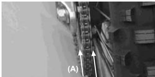
Lubrication
Lubrication is necessary after riding through rain or in the mud, or any time that the chain appears dry. A heavy oil is preferred to a lighter oil because it will stay on the chain longer and provide better lubrication.
Apply oil to the sides of the chain rollers for better oil penetration. Wipe off any excess oil.
(A). Apply oil.
HANDLEBAR
To suit various riding positions, the handlebar position can be adjusted front to rear.
Handlebar position adjustment
Loosen the handlebar holder (A) screws (B), turn the handlebar and place it in the desired position.
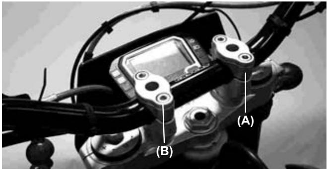
Tighten the bolts, front first and then the rear, to 25 Nm of torque.
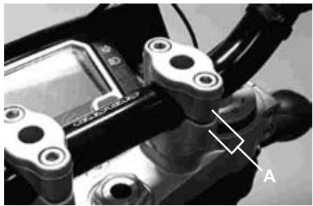
If the handlebar is installed correctly, there will be an even gap at the front and rear after tightening (A).
BRAKES
Disc and disc pad wear is automatically compensated for and has no effect on the brake lever or pedal action. So there are no parts that require adjustment on the brakes except brake lever free play and brake pedal position
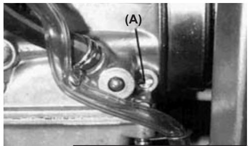
Front brake lever free play
Adjust the front brake lever (A) to match your requirements. To adjust, loosen the nut (B). After adjustment, tighten it securely. Then check that the brake response is correct.
Rear brake pedal position
When the brake pedal is in rest position, there should be a free play of 10 mm.
Check the brake for good braking power and no brake drag.
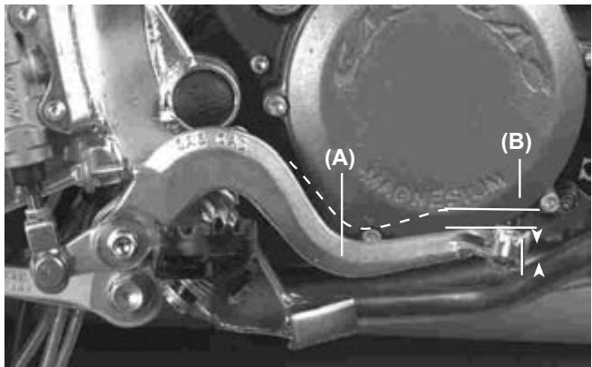
(A). Brake pedal.
(B). 10mm free play.
WARNING
If the brake pedal feels spongy when it is applied, there might be air trapped in the brake pump or the brake may be defective. Since it is dangerous to operate the motorcycle under such conditions, have the brake checked immediately.
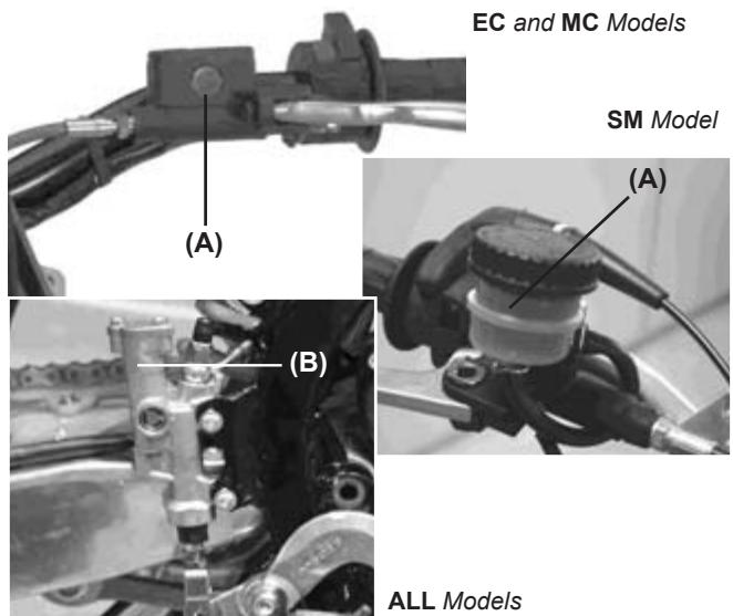
Brake fluid
Inspect the brake fluid level and change it periodically. The brake fluid should also be changed if it becomes contaminated with dirt or water.
Liquid recommended
Use D.O.T 3 or D.O.T 4.
Brake fluid level inspection
The front (A) and rear (B) reservoirs must be kept more than half full with brake fluid. If the brake fluid is insufficient, add brake fluid.
CAUTION
Do not spill brake fluid onto any painted surface. Do not use fluid from a container that has been left open or that has been unsealed for a long time. Check for fluid leakage around the fittings. Check for brake hose damage.
WARNING
Do not mix different types of fluid. Change the brake fluid in the reservoirs completely if the same type of brake fluid is not available.
Brake wear inspection
If the thickness of either pad, front and rear, is less than 1mm , replace both pads as a set. Pad replacement should be carried out only by an authorized GAS GAS dealer.
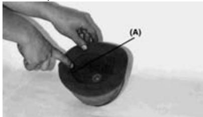
STEERING
The steering should always be kept adjusted so that the handlebar will turn freely but without free play.
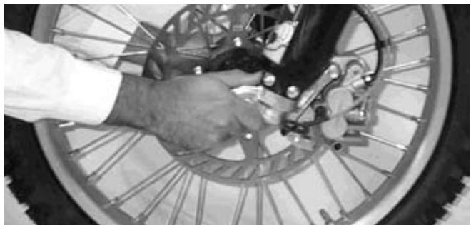
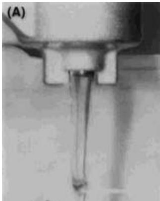
To check the steering adjustment use a stand under the chassis, and lift the motorcycle off the ground. Move the handlebar lightly to either side; if the handlebar continues moving under its own momentum, the steering is not too tight. Squatting in front of the motorcycle, grasp the lower end of the front fork (at the axle), and push and pull the fork (as shown on the previous photo); if free play is felt, the steering is too loose.
If the steering needs adjustment
- Use a stand or a special support to stabilize the motorcycle.
- Raise the front wheel off the ground.
- Remove the handlebar (A) by loosening the handlebar holder screws and removing the upper holders.
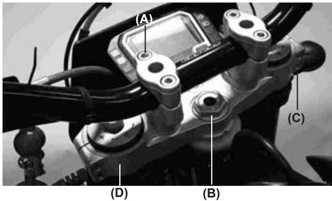
- Loosen the steering stem nut (B).
- Loosen the screws of the suspension top bridge (C) and remove it.
-
Turn the steering adjustment nut with the special wrench to obtain the proper adjustment.
-
Install the suspension top bridge (D).
- Tighten the steering stem nut, and front fork washers and screws.
Steering nut: 44 Nm (4.5 Kgm).
Suspension top bridge: 22 Nm (2.25 Kgm).
- Check the steering again, and readjust if necessary.
- Install the removed parts.
STEERING BLOCKAGE
As indicated by its name, this mechanism allows us to lock the handlebar. Is located in the steering pipe.
You have to turn the handlebar completely to the right, next insert the key, turn left, press, turn right and remove the key.
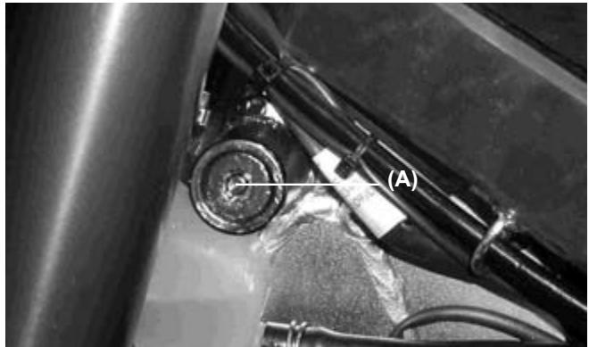
(A). Steering lock.
CAUTION
Never leave the key in the latch. If the steering is turned to the left with the key inerted in the latch it will be severely damaged.
FRONT FORK
The front fork should always be adjusted for the rider's weight and road conditions. The adjustments must be performed in 4 steps:
- Air pressure: Air pressure affects the fork travel. The air pressure increases as the fork heats up, in other words it varies as a function of time of operation. We do not recommend using air pressure, because the suspension has been designed to work without air pressure.
- Rebound and compression dampening adjustment: This adjustment affects how quickly it rebounds. The fork rebound dampening adjuster has 18 positions. The tightest position is full hard. The position 12 from close is the standard setting, and position 18 from close is full soft.
- Oil level adjustment: The effects of higher or lower fork oil level are only felt during the final 100mm of fork travel. A higher oil level will make the fork rebound faster. The lower the oil level is the fork rebound will be slower.
- Fork spring: Optional springs are available that are softer and stiffer than standard.
Air Pressure
The standard air pressure in the fork is atmospheric air pressure. The air pressure increases as the fork heats up, because of this the fork action becomes harder.
- Using a stand under the frame, and stabilize the motorcycle.
- Place a support under the engine so that the front wheel is raised off the ground.
- Remove the purge screw at the top of the front fork to bleed the air out.
(A). Air purge screw.
Rebound Dampening Adjustment
- To adjust the rebound, turn and hand tighten the adjuster knob (A) located at the top of the front fork.
- Adjust the rebound to suit the rider's preference under determined conditions.
(A). Adjuster knob.
Use the standard settings to adjust the rebound (turn it 6 positions counterclockwise).
CAUTION
The left and right fork tubes must be at the same level and aligned with the top bridge.
Compression dampening adjustment
- To adjust the compression, turn with your finger the adjusting knob located at the top of the front fork.
- Adjust the compression to suit the rider's preference under determined conditions.
- Use the standard measures to adjust the compression (turn it 6 positions counterclockwise).
Oil level adjustment
- Place a stand under the motorcycle engine (to keep it in a straight and stable position).
- Remove the handlebar screws and remove the handlebar.
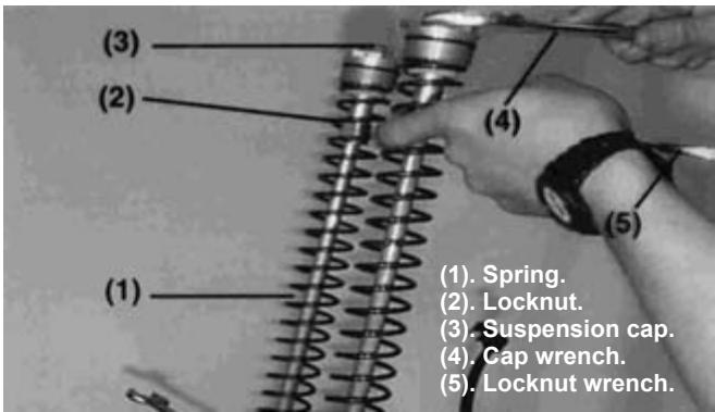
- Remove the suspension caps from the tubes.
- Compress the front fork slowly all the way.
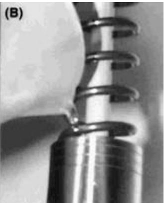
- Lift the fork springs.
- Hold the suspension tube cap with a spanner, the loosen the cap locknut.
- Remove the suspension tube caps.
- Remove the suspension srping guide.
- Use a wrench to remove the fork springs.
- Put the oil level gauge on the upper portion of the fork tube, and measure the distance from the top of the fork tube to the oil level.
Standard oil level
110mm
(A). Drain oil.
(B). Add oil.
Adjust the oil level as required within the adjustable range using the following oil:
Oil recommended by the manufacturer.
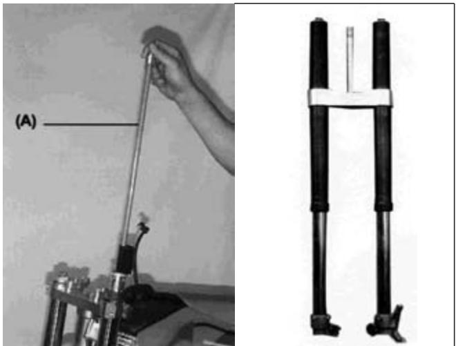
(A). Hydraulic rod.
- Pull the hydraulic rod (A) out slowly.
- At this time, the fork oil pours out of the hydraulic rod hole, keep it raised to let it drain until it stops.
- Install the fork spring (1) inside the fork tube.
- Tighten the suspension spring and insert the wrench (5) in the locknut (2) to lock the cap (3).
- Install the suspension cap (3) in the fork tube and tighten it to 29 Nm.
- Mount the other fork.
- Install the parts removed.
Suspension tube spring
Different springs are available in accordance with the rider's weight or the road conditions.
- Harder springs make the fork stiffer, and rebound action quicker.
- Softer springs make the fork softer, and rebound action slower.
Suspension top bridge position adjustment
Make sure the front tire does not rub against the fender when the fork tubes are compressed fully. Make this adjustment to a minimum of 5 mm.
| CAUTION |
| The suspension tubes, both right and left, must be adjusted evenly. |
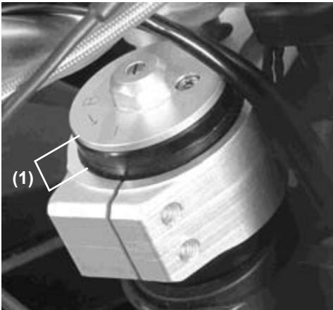
(1). Suspension top bridge position.
REAR SUSPENSION
The rear suspension is composed of the shock absorber, swingarm, linkages and torque rod.
Generally speaking, the operating characteristics are similar to the front fork. But its unique characteristic is that it has, besides the shock absorber, an articulated quadrilateral composed of the linkages and torque rod.
To match various riding condition types, the shock absorber spring can be adjusted or replaced with an optional one. Also the dampening force can be easily adjusted, this feature makes it unnecessary to change oil viscosity.
Shock absorber extension adjustment
To adjust, turn by hand the extension adjuster in the lower part of the shock absorber until a "CLICK" is heard.
Total number of adjustments possible is: 40 "CLICKS".
Rebound adjustment standard measures:25 "CLICKS".
(Counterclockwise from fully closed position).
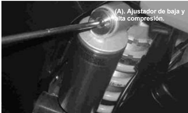
High compression adjustment
Use a screwdriver for adjustments. The control has 4 complete turns. As the control is closed the compression will be harder, on the other hand as it is opened it will be softer. Normally, the standard measurement would be 1,5 turns from the completely closed position.
Spring adjustment
- Remove the seat and side covers.
- Loosen the air cleaner duct clamp screw.
- Remove the muffler.
- Remove the subframe with the air cleaner box.
Suspension spring
The standard spring is 5.2 (250 cc, 300 cc) - 5.0 (125 cc, 200 cc) - 5.6 (MC). The spring length preloaded with the shock absorber at rest is 258 mm.

(A). Nut.
(B). Spring.
(C). Locknut.
- Tighten the locknut securely.
- After adjustment, move the spring up and down to make sure that the spring is fully seated.
- Install the parts removed.
Rear shock absorber spring replacement
Harder and softer springs are available. If the standard spring is not adequate for your purpose, select a proper one according to the rider's weight and the road conditions.
- Using the harder spring:The rebound is quicker.
- Using the softer spring:The rebound is slower.
NOTE
Refer to the suspension adjustments on page 47.
WARNING
Improper installation of the rear shock absorber spring may cause the spring and any of its related parts to be ejected at high velocity. Always wear eye and face protection. The installation of these parts should be performed by an authorized dealer.
WHEELS
Tires
- Tire pressure affects traction, and tire life.
- Adjust the tire pressure to match road conditions and rider's preference, but do not stray too far from the recommended pressure.
NOTE
Tire pressure should be checked when the tires are cold before riding.
Road conditions
- When the road is wet, muddy, sandy or slippery, reduce the tire pressure.
- On gravel roads or hard terrain, increase the tire pressure.
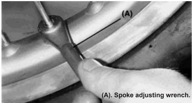
Spokes and wheel rims
The spokes on both wheels must be tightened evenly and should not be allowed to have free play. Unevenly tightened or loose spokes will cause wheel rim runout, the other spokes will be stressed and might break.
Wheel rim runout
Place a dial indicator at the rim side, and spin the wheel by hand to measure the axial runout.
Place the dial indicator at the inner circumference of the wheel and spin the wheel, the difference between the highest and lowest quantities is the runout.
If the runout is not excessive it can be corrected tightening or loosening some spokes with the spoke adjusting wrench (B). If the wheel rim is curved or bent it must be replaced.
NOTE
A welded area on the rim may indicate excessive runout. Disregard this when measuring rim runout.
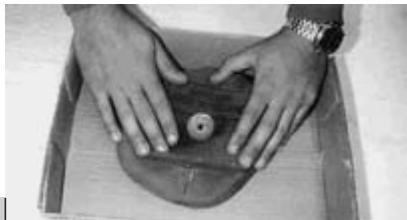
CLEANING
1- Preparation for washing
Before washing the motorcycle, precautions must be taken to prevent water from entering the following parts of the motorcycle.
Exhaust: Cover it with a plastic bag tightened with rubber bands.
Clutch and brake levers, hand grips, and engine stop button: Cover these parts with plastic bags.
Air cleaner intake: Cover the opening with tape or with a rag.
2-Where to be careful
Avoid spraying water with any great force near the following areas:
- Brake calipers and brake pump piston.
- Ignition coil or into the spark plug cap.
- Front and rear wheel hubs.
- Steering bearings.
- Rear suspension system.
- Swingarm bearings.
CAUTION
To avoid excessive ageing of the plastic parts and other washable pieces of the motorcycle, it is suggested that these items must be washed carefully. If the washer applies water at high pressure and/or temperature, take the precaution of maintaining the washer outlet gun at a distance of 30 centimeters minimum, this will ensure the correct gloss of the plastics and maintain adherence of the self-adhesive labels that decorate the motorcycle.
3-After washing
- Remove the plastic bags, and clean the air cleaner intake.
- Lubricate the points listed in the lubrication section (see pag. 40).
- Start the engine and let it run for 5 minutes.
- Check the brakes before operating the motorcycle.
WARNING
Never wax or lubricate the brake disc. Loss of braking and an accident could result. Clean the disc with trichloroethylene or acetone.
BOLTS AND NUTS TIGHTENING
Every day before riding, check the tighteness of the bolts and nuts described here. Also check that all other fasteners are in place and in good condition.
1- Front and rear wheel.
2-Front fork.
3- Handlebar.
4- Clutch lever holder screw.
5-Cylinder head bolt.
6- Spark plug.
7-Cylinder nuts.
8- Air cleaner box holder bolts.
9- Trailing plate bolts.
10-Spokes.
11- Front axle bolt.
12- Brake hose screw.
13-Radiator bracket bolts.
14- Engine holder bolts and nuts.
15-Gearshift pedal bolt.
16- Subframe bracket bolt.
17-Chain guide bolts.
18-Chain adjuster nut.
19- Seat mounting bolts.
20- Subframe bolts.
21- Rear shock absorber bolts.
22- Exhaust mounting bolts.
23- Suspension top bridge bolts.
24- Steering stem nut.
25- Brake lever bracket screw.
26- Rear axle nut.
27- Linkage mounting bolt.
28- Rear brake pedal bolt.
29-Torque rod mounting bolt.
30- Swingarm shaft nut.
31- Kick-start pedal bolt.
32- Kick-start pedal nut.
33- Front brake hose fastening screw.
Torque Values Table
Tighten all bolts and nuts to the proper torque using an adequate wrench. A bolt or nut loose might damage the motorcycle or even cause an accident.
| PART NAME | Nm | |
| FRA M E | Brake caliper mounting bolt | 25 |
| Disc mounting screw | 10 | |
| Engine mounting bolt | 36 | |
| Front axle bolt | 51 | |
| Front brake hose mounting bolt | 6 | |
| Suspension clamp bolt | 29 | |
| Steering nut | 98 | |
| Rear axle nut | 98 | |
| Rear brake pedal bolt | 9 | |
| Subframe bracket bolt | 26 | |
| Rear shock absorber bolt | 39 | |
| Rear drive plate nut | 29 | |
| Spokes | 1.5 | |
| Steering stem nut | 4 | |
| Torque rod bolt | 81 | |
| Rear linkage bolt | 81 |
| PART NAME | Nm | |
| EN G I N E | Cylinder head screws | 25 |
| Cylinder nut | 25 | |
| Engine drain plug | 20 | |
| Kick-start pedal bolt | 20 | |
| Kick-start pedal nut | 25 | |
| Gearshift pedal bolt | 15 | |
| Spark plug | 27 | |
| Water pump cover drain plug | 9 | |
| Crankcase screws | 10 | |
| Starter pedal plate screw | 8 | |
| Ignition motor stator screws | 8 | |
| Ignition motor coil nut | 40 | |
| Selector spring fixing screw | 15 | |
| Primary nut | 40 | |
| Clutch spring screws | 10 | |
| Valve control support screws | 10 | |
| Valve control nuts | 8 | |
| Reed valve screws | 10 | |
| Thermostat housing screws | 10 | |
| Clutch housing screws | 10 | |
| Valve housing screws | 8 | |
| Ignition housing screws | 10 |
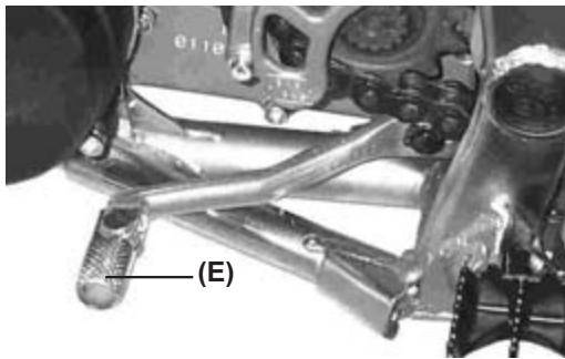
LUBRICATION
Lubricate the points shown here, apply either engine oil or grease, periodically or whenever the vehicle has been operated under wet or rainy conditions, and especially after using high water pressure. Before lubricating each part, remove any rusty spots with rust remover and wipe off any grease, oil, or dirt.
General lubrication
- Clutch lever (A).
- Front brake lever (B).
Rear brake pedal (C).
Rear brake bearing (D). - Gearshift pedal (E).
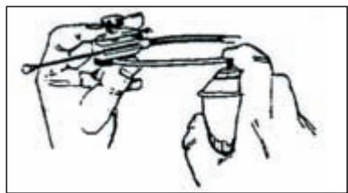
Use an aerosol with a tube for pressure lubrication:
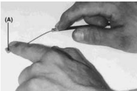
Apply grease inside the gas cable (A).
Drive Chain Lubrication
Lubricate the drive chain after driving on wet terrein or when the chain looks dry. A high viscosity oil is preferred rather than a lower viscosity because it will stick to the chain longer and lubricate the chain better.
Apply oil to the sides of the chain rollers (A) for better oil penetration. Wipe off any excess oil.
TUNE-UP
1. CARBURETOR TUNE-UP
Mixture
First step is to establish a basic knowledge on the identification and operation of carburetor components. Change settings in accordance with the temperature:
| Condition | Mixture | Change setting |
| Cold air | Lean | Rich |
| Warm air | Rich | Lean |
| Dry air | Lean | Rich |
| Low altitude | Standard | Standard |
| High altitude | Rich | Lean |
NOTE
The main jet should be increased or decreased 1 to 5 sizes and tested until the engine gives maximum power.
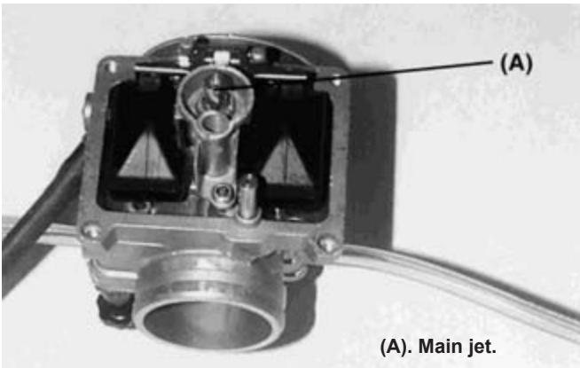
Main jet
It has a great overall effect. The number stamped on lower part of the main jet indicates the size of the hole metering fuel. A greater number corresponds to a bigger hole which supplies more fuel.
WARNING
Gasoline is extremely flammable and can be explosive under certain conditions. Always stop the engine and do not smoke. Make sure the area is well ventilated and free from any source of flame or sparks (this includes any appliance with a pilot light).
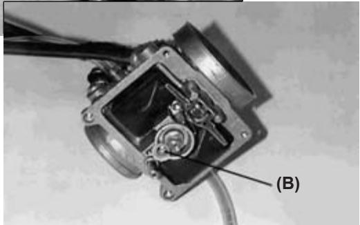
ldling nozzle and mixture adjustment screw
Controls the mixture from the closed position to an opening of 1/8 of throttle range, but has little effect on full throttle. To adjust the mixture in this range, the air screw can be turned to change the air flow through the circuit, or the slow jet can be changed to provide more or less fuel. Start by turning the air screw. Screwing it in richens the mixture. The air screw must be turned from a lightly seated position. Make changes in 1/2 turn increments. If turning the screw between 1 and 2.5 turns does not give the desired results, change the slow jet (B) one step and tune up with the air screw (A).
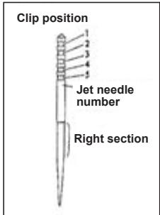
Carburetor jet needle
The jet needle and jet needle hole together have their greatest effect in the one-half throttle range. The needle moves in and out of the jet needle hole; since the needle is tapered, its position in the jet determines the amount of fuel allowed to flow.
There are five grooves in the upper section of the needle where a circlip fits. This clip locates the needle in the throttle valve and determines its relative position in the jet needle hole, and provides a rich mixture. Moving the clip to the top will provide a lean mixture. Change the clip position one step at a time. The straight area of the needle affects throttle valve response in the small openings range.
Test runs with the motorcycle
- Warm up the engine with the carburetor at the standard setting, and inspect the operating conditions of the spark plug.
- Test-ride the motorcycle with the throttle opened.
Symptoms of improper settings
If your motorcycle exhibits one of the following symptoms the changes must be adjusted. Before attempting any changes, make sure that everything else is in good operating condition.
Check the condition of the spark plug, make sure the ignition timing is correct, service the air cleaner element, decarbonize the exhaust tube
If you machine has run properly up to this point, it is possible that the problem is elsewhere; changing the carburetor settings in such a case would probably be a waste of time.
| Spark plug condition | ||
| Correct | Insulator is dry & light tan color | |
| Too lean | White color insulator | Replace the main jet to one step larger |
| Too rich | Insulator is wet & black color | Replace the main jet to one step smaller |
- Set the carburetor so that the engine delivers satisfactory power with the throttle valve opened.
- If the air-fuel mixture is too lean, the engine tends to overheat and may be seized. On the other hand, if it is too rich, the spark plug easily gets wet and causes misfires. The proper mixture varies depending on atmospheric conditions. Taking these conditions into consideration, adjust the carburetor settings properly.
NOTE
Keep in mind that the carburetor components that regulate fuel flow and the screw that control the flow of air must be tight.
The standard competition measurements EC 250 are an example.
| FUEL | UNLEADED |
| Throttle valve | 7 |
| Idle jet | 38 |
| Needle | N1EF |
| Main Jet | 170 |
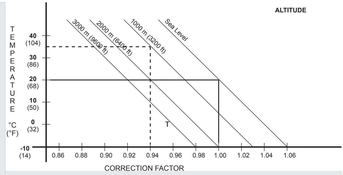
Correction factors:
(For altitude or temperature changes).
- Find the correction factor to adjust the carburetor.
Example: 1000 meters altitude with an air temperature of 35^ . The correction factor is 0.94. - Using the correction factor, select the correct slow jet and main jet.
Example: For a correction factor of 0.94 multiply the jet size by that number.
Idle jet: # 40 x 0.94 = # 38.
Main jet: # 180 x 0.94 = # 170.
-
Find the correction factor on the Jet Needle / Air Screw chart and change the jet needle clip position and air screw opening as indicated.
-
Jet needle clip setting: from the 3rd groove to the 2nd groove.
- Air screw opening: 112 + 1 turn = 212 turns out.
NOTE
For the following recommendations to be accurate, you must use the standard settings as a base-line. Also do not change any of the settings until you have determined what changes are necessary. All specifications are based on the use of the fuel and oil specified.
| NEEDLE POSITION / AIR SCREW OPENING | |||||
| CORRECTION FACTOR | 1.06 or higher | 1.06 - 1.02 | 1.02 - 0.98 | 0.98 - 0.94 | 0.94 or LOWER |
| NEEDLE POSITION | LOWER CLIP 1 POSITION | SAME | SAME | SAME | RAISE CLIP 1 POSITION |
| AIR SCREW OPENING | TIGHTEN 1 TURN | TIGHTEN 1/2 TURN | SAME | LOOSEN 1/2 TURN | LOOSEN 1 TURN |
2. SUSPENSION TUNE-UP
This adjustment is very critical because if an improperly tuned suspension will keep even the best rider from attaining the full benefit of his machine's ability. Check the suspension in accordance to the rider and the terrain conditions.
- If the motorcycle is new, break-in the suspension with at least one hour of riding before making any setting evaluations or changes.
- The three factors which must be considered are rider's weight, rider's ability, and terrain conditions (additional influences include the rider's style and position on the motorcycle).
- If you have a problem, test by changing your riding posture or position so it can be deduced.
- Adjust the suspension to match the rider's strong points. If he is fast through the corners, adjust the suspension to allow fast cornering.
- Make setting changes in small increments; a little bit goes a long way, and it is very easy to overadjust a setting.
- The front and rear suspension should be balanced; when one is changed, the other might need to be changed similarly.
- When evaluating suspension performance the rider must make every effort to ride consistently and recognizing the effects of his input; such things as changes in rider position and increasing fatigue may lead to incorrect judgments about necessary setting adjustments.
- When the proper settings have been determined for a particular terrain, the settings should be written down for later reference when returning to the same type of terrain.
- Before making any changes and also every 5 fill-ups, lubricate the swingarm bearings, torque rod, linkages and O-rings, this precaution will prevent excessive friction that can affect the suspension performance.
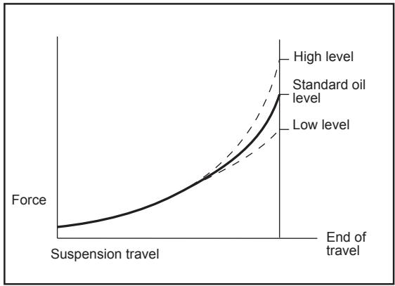
Front fork
The oil level is adjustable. A change in the oil level will not affect the lower part of travel, but it will have an affect on the upper part of travel:
- When the oil level is raised:
The spring effects become more progressive, and the front fork action feels harder at the end of travel.
If the front suspension is making jounce stops, raise the oil level 10 mm. This increase will provoke a change in upper part of travel of the spring.
- When the oil level is lowered:
The spring effects are less progressive, and the front fork action does not become hard at the end of travel.
- Change the oil level correctly and the fork will work more at the end of fork travel.
Oil level adjustment
Adjust the front fork oil level (refer to the maintenance chart).
Troubleshooting Improper Settings
Listed below are some symptoms of improper suspension settings and the most likely means of correcting them.
The proper settings can be achieved by applying the information in this chapter in a scientific manner. Take time to think about the changes you believe necessary, check them against the symptoms and cures described here, and make the changes in small increments, and take notes on the changes and their effects.
Symptoms of the front fork
-
The front fork is too stiff:
-
Incorrect rebound adjustment.
- The springs are too hard.
- Too much oil.
-
Oil too dense.
-
The fork becomes hard at the end of travel:
-
The oil level is too high.
-
The fork operates but slides hard:
-
Oil too dense.
-
Degraded fork oil.
-
Too soft:
The fork shakes excessively when slowing down or applying brakes
- Fork oil level is low.
- Springs are too soft.
- Oil too light.
- Degraded fork oil.
- Incorrect rebound or compression.
Symptoms of the rear shock absorber:
-
Too hard:
-
The suspension is too stiff
-
Compression damping is too high.
Spring is too hard. -
Is hard to ride
-
Unbalanced condition between the spring and rebound (too low).
-
The spring is hard or preloaded too much
-
Too soft:
On landing after a big jump, the suspension makes jounce stops.
- Soft spring or compression damping is too soft.
- Degraded shock absorber oil
Determining the proper settings:
- Standard Settings
From the factory, the machine is set up for an average-weight rider with average riding abilities. Hence, if the actual rider's weight or if his riding experience and abilities are considerably superior or below the average, it is necessary to make adjustments to the suspension.
- Readjustment of the suspension:
| Ground surface | |
| Smooth | Soft spring |
| Rough | Hard spring |
Riding experience
Beginner: Soft spring with rebound.
Experienced: Harder spring.
Rider's weight
Heavy: Hard spring.
Light: Soft spring.
Type of racing circuit
-Many corners:
Lower the front end slightly (Raise the fork tubes 5mm ). This increases agility.
- Fast course with many jumps:
Raise the fornt end slightly (Lower the fork tubes 5mm
- Deep potholes or sandy ground:
Raise the front end slightly to gain stability.
After making such preliminary adjustments, begin the actual on-track testing and evaluation.
CAUTION
1- Make changes one step at a time.
2- Make sure the rider is consistent in this evaluation.
3- A change in the front suspension requires a change in the rear, and vice versa.
Front and rear compatibility:
Use this procedure to determine if the suspension is balanced. Place the motorcycle upright. While standing next to the right side of the motorcycle, hold the front brake and press the rear brake pedal firmly. If the motorcycle maintains its level attitude as the suspension is compressed, the spring rates are well balanced. Sit astride the motorcycle and take a riding posture. Next check to see that the motorcycle is in a horizontal position. If one end drops noticeably more than the other, the front and rear are not compatible and must be readjusted to achieve a better balance.
This is one of the most effective adjustment procedures but suspension settings will vary depending on the conditions at the terrain and the rider's preferences.
Does the motorcycle skids when driving down hill or when accelerating out of a curve?
Front fork is too soft.
- Increase the compression or rebound damping.
- Increase the oil level 10mm
- Use a harder spring, or increase spring preload.
Does the front end tends to turn inward?
Front fork is too soft.
- Increase the compression or rebound damping.
- Increase the oil level 10mm
Does the front end slips when entering in a curve?
- Decrease the compression or rebound damping.
- Bleed air trapped in the fork.
- Decrease the oil level 10 - 20mm
- Use a softer spring.
Does the front fork fails to respond to small potholes while managing wide turns?
Front Fork is hard:
- Decrease the compression or rebound damping.
- Decrease the oil level 10mm
- Use softer duty spring.
Does the rear end jumps when braking over potholes?:
The shock absorber probably has too little rebound damping.
- Increase the rebound damping.
Does the rear tire lacks traction when coming out of corners?:
-
The shock absorber is too hard:
-
Decrease the rear shock absorber spring.
- Decrease the compression damping.
- Use a softer spring.
Does it land on the front wheel in high speed jumps?:
(there may be a problem with the driver's posture)
Rebound damping too soft or hard spring.
- Increase the rebound damping.
- Decrease the shock absorber spring preload.
- Decrease the compression damping.
Does the suspension jounce stops at front and rear of the motorcycle in high speed jumps?:
(If this occurs 1 or 2 times in the same lap of the race)
Front and rear suspension system are too soft:
- Front: Increase the oil lever and / or use a harder spring.
- Rear: Increase compression damping or use a harder spring.
NOTE
After any adjustment, check front and rear compatibility.
Adjustments that depend on the conditions of the jounce stops (rear shock absorber).
- Suspension jounce stops at low speed, increase the spring preload to the maximum setting.
- Jounce stops after 3 or 4 successive jumps, decrease the rebound damping.
NOTE
The rear shock absorber due to its setting possibilities may mislead some riders.
a) The rear shock absorber does not jounce stop when the spring is correct for the total weight of the machine and rider.
b) A jounce stop sensation of the shock absorber may be caused by the rider's inexperience in riding a machine with a harder spring.
Observe the rear end while it jumps; if it does not approach the stopper, try lowering the sping preload.
Gearshift
Select the ratio development. Preconditions:
Race conditions: vary the transmission replacing the rear pinion. Fast race: use pinions with less teeth.
Winding road or soft or sandy uphill surface: use pinions with more teeth.
- If the straight portion of the course is long, the ratio development can be extended and due to this the speed increases.
-
When the course has many corners or uphill or is wet, the ratio development will be reduced so that gear shifting is possible at low speed.
-
Actually, the speed can be changed depending on the terrain conditions on the day of the race and therefore, be sure to run through the racing circuit prior to a race and set the machine suitable for the entire course.
- If the straight portion of a course on which the machine can be run at maximum speed is long, the motorcycle should be set so that the maximum machine speed can be developed towards the end of the straight course, but care should be taken not to over-rev the engine.
- It is very difficult to adjust the motorcycle to be best setting for all portions of the circuit. Therefore, determine which circuit portions will have the greatest effect on lap time and set the motorcycle for these portions. In this manner the motorcycle will deliver best performance for the entire circuit.
Special care according to the terrain conditions.
- In dry, dusty conditions special care must be given to keep the air cleaner element clean since it accumulates dirt and the engine operates too "rich".
- When riding on wet heavy clay the mud adheres to the tires and other parts of the vehicle. The mud can add significantly to the weight of the vehicle and therefore reduce performance. Take care so that the engine is not overheated. The same applies when driving in deep sand.
- In muddy or sandy conditions loosen the drive chain slack to release its tension.
- Check chain and sprocket - pinion wear frequently when riding in mud or sand since wear is increased under these conditions.
SPARE PARTS AVAILABLE
Refer to the sparts parts catalogue.
FINAL RECOMMENDATIONS
PREVENTIVE ADVICE
Before you ride the motorcycle, take all the time you may require to check your motorcycle, carry out the periodical upkeep and check all functions. In different sections of this manual you will find data and work specifications that must be done at an autorized GAS GAS dealer, because of this and to extend the useful life of the motorcycle, all periodical inspections must be carried out by specially trained professionals at a GAS GAS Post-Sale Service Shop.
Poor maintenance work of the motorcycle or not taking proper care of any problem, even if its is a small concern, can cause severe personal injury and may lead to death.
SAFE RIDING OF YOUR MOTORCYCLE
Safe riding of a motorcycle does not only depend on the vehicle. The driver's intelligence and common sense are key factors to be taken into consideration. It is recommended that you practice your favorite sport wearing all the necessary safety equipment (helmet, protection gear, boots, etc.).
LEGAL ADVICE
In the interest of technical development we reserve the right to modify the construction, the equipment and accessories of the motorcycle. It is understood that all measurements, weights and power data must include their respective tolerances. The photographs included in this manual may not match the model you have purchased. The descriptions and the illustrations may vary depending on the volume of equipment and accessories of your motorcycle and also of the versions exported. Because of this, there can be no liability except in case of errors, misprint or omission.
GAS GAS MOTOS, S.A. reserves the right to make changes and/or modifications at any time without notice.
HOMOLOGATION (SM y EC):
The vehicle you have just acquired has been homologated under the directives of the EU and complies with all the homologation requirements demanded.
Compulsory homologation elements required, among others, when travelling on a public road and to meet periodical vehicle inspection approval at state controlled plants are listed below.
Among other requirements, all homologation components are identified with a determined and registered mark.
| List of elements required: | Quantity / motorcycle |
| - Manufacture identification plate | 1 |
| - Catalyzed exhaust | 1 |
| - Muffler | 1 |
| - Carburettor jets | 1 |
| - Front and rear turn signals | 4 |
| - License plate holder | 1 |
| - Speedometer | 1 |
| - Electrical installation, homologated lights | 1 |
| - Horn | 1 |
| - Rearview mirror | 2 |
| - Antitheft system | 1 |
| - Antimanipulation plate (125 cc version) | 1 |
| - Secondary air valve | 1 |
| - Air filter restriction | 1 |
| - Throttle limiter (EC 200, 250, 300) | 1 |
Each one of the homologation components must form part of the vehicle and in case of loss, breakage or malfunction it is recommended that the owner contact his official dealer to correct this problem.
PREPARATION FOR COMPETITION
(1). Check:
- Front axle and bridges nuts tightness.
- Front fork clamp bolts tightness.
- Handlebar clamp bolts tightness.
- Throttle grip screws tightness.
- Throttle grip operation and apply grease.
- Front and rear brake hose inspection.
- Front and rear brake fluid level.
- Front and rear brake disc and caliper inspection.
- Front and rear brake operation test.
- Fuel tank inspection.
- Verify the installation of all cables.
- Engine mounting bolts tightness.
- Verify output pinion.
- Gearshift pedal bolts tightness.
- Transmission oil level.
- Battery charge.
- Throttle body.
- Linkage tie rod mounting bolts tightness.
- Linkages mounting bolts tightness.
- Rear shock absorber bolts tightness.
- Swingarm shaft nut tightness.
- Rear axle nut tightness.
- Rear sprocket bolts and nuts tightness.
- Rear brake pedal operation.
- Seat inspection.
- Wheel spokes tightness.
- Front and rear tire air pressure.
- Drive chain slack.
- Coolant level.
(2). After 1 day of racing competition:
- Clean the air cleaner element.
- Adjust drive chain slack.
- Tighten rear sprocket nuts.
- Tighten all spokes.
- Check the tires air pressure.
- Tighten front and rear axle nuts.
- Tighten swingarm shaft nut.
- Tighten muffler and exhaust bolts and nuts.
- Tighten front and rear fender mounting bolts and nuts.
- Tighten fuel tank and seat mounting bolts and nuts.
- Check brakes.
- Check steering free play.
- Fill fuel tank.
- Check coolant level.
(3). Maintenance after riding on dusty course:
If dirt or dust gets into the engine, the crankshaft will wear out excessively. After riding, inspect the crankshaft. If the crankshaft is worn beyond the service limit, change it
(4). Maintenance after riding in rain or muddy course:
- Apply grease to swingarm pivot and the suspension system.
- Inspect the drive chain and rear sprocket and pinion wear.
- Clean the sprocket and pinion.
- Check the cylinder-piston and crankshaft bearings.
- Grease the throttle grip and cable.
STORAGE
For extended storage of the motorcycle, you must do the following:
- Clean the motorcycle thoroughly.
- Start the engine for about 5 minutes to warm up the transmission oil and then drain it (refer to the transmission section).
- Fill with new transmission oil.
- Empty the fuel tank (gasoline will deteriorate if left too long).
- Disconnect the battery.
- Lubricate the drive chain and all cables.
- Cover all unpainted metal surfaces with a coat of oil to prevent rust, do not apply oil to the brakes and rubber parts.
- Cover the exhaust pipe with a plastic bag to prevent corrosion.
- Place the motorcycle in such a position so that the wheels do not touch the ground (if this is not possible, place cardboards under the wheels).
- Cover the motorcycle to protect it from dust and dirt.
When starting off after an extended storage:
- Remove the plastic bag from the exhaust pipe.
- Tighten the spark plug.
- Fill the fuel tank.
- Check all points marked in the section "Daily Inspection Before Riding".
- General lubrication.
- Connect the battery.
The multifunction apparatus, which is waterproof, has 4-8 LED indicators on both sides of a central indicator screen. This central indicator screen, made of liquid crystal and with illumination, gives information about the rpm, speed, journey, kilometres travelled, time, average speed, maximum speed, length of time with motor running and total time, and fuel level. The data relative to the distance travelled and total time of use is stored in the memory, even when the apparatus is switched off. When the multifunction apparatus is not activated, it displays a clock.
The wheel circumference value is adaptable, as is the measuring system (metric or imperial).
The number and distribution of the LED indicators, and the amount of information on screen may vary according to model.
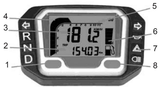
Panel
Panel description
- RESET button
- 2nd row of indicators
- 1st row of indicators
- Tachometer with bar graph
- Tachometer scale
- Fuel indicator bars (optional)
- LED indicator symbols
- MODE button
Description of symbols
| Left indicator / Green |
| Dipped headlights / Green |
| Motor oil / Red (Optional) |
| Right indicator / Green |
| Full headlights / Blue |
| Neutral / Green (Optional) |
Technical characteristics
| FUNCTIONS | Symbol | TECHNICAL CHARACTERISTICS | INCREMENTS | PRECISION |
| Bar Tachometer | f | 500 - 11.000 rpm | 500 rpm | |
| Digital Tachometer | RPM | 100 - 19.900 rpm | 100 rpm | |
| Gear change indicator | RPM | 100 - 19.900 rpm | 100 rpm | |
| Maximum Tachometer Value | 100 - 19.900 rpm | 100 rpm | ||
| Speedometer | MAX RPM | 2,3 - 300 km/h (187,5 m/h) | 0,1 km/h o m/h | ± 1% o ± 0,1 km/h / m/h |
| Speedometer | MAX | 2,3 - 300 km/h (187,5 m/h) | 0,1 km/h o m/h | ± 1% o ± 0,1 km/h / m/h |
| Average Speed | AVG | 2,3 - 300 km/h (187,5 m/h) | 0,1 km/h o m/h | ± 1% o ± 0,1 km/h / m/h |
| Distance counter 1&2 | TRIP 1&2 | 0 - 999.9 km or 0 - 624.9 miles | 0.1 km or miles | ± 0,1 % |
| Mileometer | ODO | 0 - 999,999 km or 0 - 624,999 miles | 0.1 km or miles | ± 0,1 % |
| Time in use | RT | 0:00'00" - 99:59' 59" | 1 second | ± 50 ppm |
| Total time | TT | 0:00' - 9999:59' | 1 minute | ± 50 ppm |
| Clock | L | 0:00'00" - 23:59' 59" | 1 second/1 minute | ± 50 ppm |
Initial voltage: 12v CC.
Speed sensor Non-contact magnetic sensor.
Tachometer entry CDI (capacitor discharge ignition) or ignition coil signal.
Wheel circumference adjustment 1mm - 3.999mm (1 mm increments).
Working temperature: -10^ + 80^ (engine casing interior).
Fuel sensor resistance 100 (only in models with fuel level indicator).
Functions
RPM: Bar
Tachometer with bar graph The bar graph of the tachometer displays up to 11,000 rpm.
RPM: Digital Tachometer
The rpm is shown in the second row The digital tachometer displays up to 19,900 rpm The tachometer signal can be read from the CDI (Capacitator Discharge Ignition) or the ignition coil.
Gear change indicator according to rpm
This function permits setting an indicator for changing gear at a specific rpm level. The tachometer bar flashes when the rpm reaches the specific level and stops flashing when the gear is changed.
MAX RPM: Maximum tachometer value
It appears in the 2^nd row. It shows the highest level reached by the tachometer since the last resetting of the data.
SPD: Speedometer
The speedometer information appears in the first line of the screen. It shows up to 300km/h or 187.5mph .
MAX: Maximum speed gauge
The MAX value appears in the 1st line. It shows the highest speed reached since the last resetting of the data.
AVG: Average driving speed
The AVG value appears in the 1st line. It calculates the average speed since the last RESET operation.
TRIP: Journey counter
This appears in the second line of the screen. The TRIP function contains the vehicle's accumulated mileage since the last RESET operation.
ODO: Mileometer
It shows the total mileage accumulated by the vehicle.
The data is stored in the memory, even when the device is not running.
RT: Time of use controller
It calculates the total time in use since the last RESET operation. It starts counting from the moment that movement begins.
TT: Total time of use controller
It calculates the vehicle's total time in use. It starts counting from the moment that movement begins. The data is stored in the memory, even when the device is not running.
12/24 hour clock
It shows the time in either 12 or 24 hour formats.

Fuel level indicator (only vehicles with this function)
It has 7 bars showing the amount of fuel remaining in the fuel tank. The last bar flashes to indicate that the fuel level is too low.
Operation of the buttons
MODE BUTTON
- Press the MODE button to switch from one function screen to another when the speed sensor detects no signal.
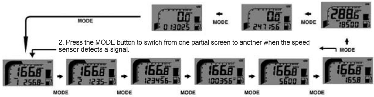
RESET BUTTON
- Press the MODE button to reach the appropriate screen, and then press RESET for 2 seconds to return the data stored in TRIP 2, MAX and MAX RPM to zero separately.
- Return the data in TRIP 1, AVG and RT at the same time. The data of the ODO, CLOCK and TT. cannot be returned to zero.
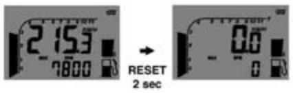
- Press the MODE button to switch to the RPM screen; accelerate to the rpm which is desired for the gear change indicator to be activated.
- Press the RESET button to confirm and establish the gear change indicator according to the rpm.
- The tachometer with bar graph and a LED will flash to indicate the need to change gear.
- Use the steps 1 and 2 to readjust the gear change according to RPM.
Multifunction and wheel circumference adjustment
The configuration operations include the 12/24 hour clock, the gear change according to rpm indicator, the number of engine revolutions by signal, the wheel circumference and the units of measurement The configuration must be carried out step by step. The computer will return automatically to the main screen if no button is pressed in any adjustment screen for 75 seconds.
- Press the MODE and RESET buttons to switch to the adjustment screen. In the adjustment screen, press the RESET button to increase the value of the flashing digits or to convert units, press the MODE button to confirm the configuration and move on to the next digit or the next adjustment screen to be configured. Press the MODE button for 2 seconds in any adjustment screen to conclude the configuration and return to the main screen.
- The screen shows 12 or 24h and the symbols: XX: XX-XX, and AM/PM if the 12h option has been selected.
- When the RESET button is pressed the 12/24h system changes, and when MODE is pressed, the configuration concludes and the configuration of the clock digits opens.
- Press the RESET button to increase the value of the flashing digit one by one; press the MODE button to confirm the configuration and pass on to the following digit.
- Press the MODE button to switch to the adjustment screen of the gear change according to rpm, once the clock has been configured.
- The screen will show RPM rXXX00. Press the RESET button to increase the value of the digit one by one; press the MODE button to confirm the configuration and pass on to the following digit.
- Press the MODE button to switch to the adjustment screen for the engine revolution by signal, once the gear change according to rpm configuration is completed.
- The screen will show SPC-X.X RPM, with 1.0 as the default value. There are 4 options 1.0, 2.0, 3.0 and 0.5. They correspond to the number of revolutions for each signal. For example, a value of 2.0 means that the motor turns over twice to produce a signal.
- Press the RESET button to move between the four values . Press the MODE button to confirm the configuration and to move on to the wheel circumference adjustment screen
-
When cXXXX appears on screen, the "c" stands for "circumference" and is followed by four digits by default; the flashing digit is the one to be changed.
-
Press the RESET button to increase the value of the flashing digit one by one; press the MODE button for 2 seconds to confirm the digit change and pass on to the following digit.
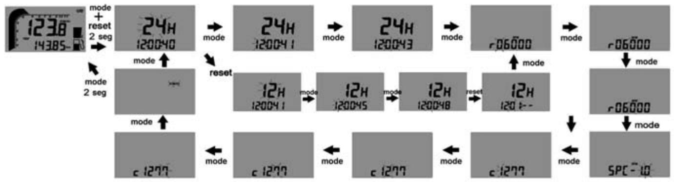
TROUBLESHOOTING
NOTE
This is not an exhaustive list of malfunctions, it only shows the most common problems.
| MALFUNCTION | POSSIBLE CAUSE | REMEDY | |
| 1 | Engine does not crank | -Seized crankshaft.- Seized cylinder / piston / jornal bearing.- Seized transmission assembly.- Motorcycle inactive too long.- Wet or fouled spark plug.- Flooded engine.- Incorrect air/fuel mixture.- Exhaust valve stuck open | -Go to a specialized workshop.- Go to a specialized workshop.- Go to a specialized workshop.Drain old fuel out of the tank. With the fuel tank filled with new fuel, the engine will start immediately.- Clean and dry or replace the spark plug.- In order to "relieve the engine", accelerate to max. speed, press the starter pedal 5 or 10 times. Then, start the engine as described above. If the engine fails to start, remove the spark plug and dry it.- Clean the fuel tank air vent. Adjust the air cleaner duct.- Verify the exhaust valve and repair as necessary. |
| 2 | Engine cranks but then stops | -Incorrect air supply.- No fuel. | -Close the starter. Clean fuel tank air vent. Adjust the air cleaner duct.- Fill up the fuel tank. |
| 3 | Engine overheating | - Insufficient cooling liquid in the circuit.- Radiator is dirty or partially restricted. | -Fill up cooling liquid, verify the refrigeration system watertightness.- Clean radiator fins or replace it. |
| 4 | The engine operates irregularly | - Spark plug dirty, or misadjusted.- Poor contact with the spark plug cap or cable loose in cap. | - Verify the spark plug condition and clean it accordingly, tighten or replace it.- Verify the spark plug cap condition. Replace if deteriorated. |
| 4 | The engine operates irregularly | - Ignition rotor damaged. - Water in fuel. | - Replace the rotor. - Drain the fuel tank and fill up with new fuel. |
| 5 | Engine lacks power or poor acceleration | - Fuel supply defective. - Dirty air cleaner. - Leaking or deteriorated exhaust system. - Dirty carburetor jets. - Worn or damaged crankshaft bearings. - Clutch slips. | - Clean the fuel system and verify its operation. - Clean or replace the air cleaner. Verify its operation. - Verify if the exhaust system is damaged. Replace the muffler fiberglass packing, if necessary. - Disassemble the carburetor and clean all jets. - Replace the crankshaft bearings. - Verify the clutch operation. Go to a specialized workshop. |
| 6 | Abnormal engine noise | - Ignition problem. - Overheating. | - Go to a specialized workshop. - Refer to section 5. |
| 7 | Detonations from the exhaust pipe | - Carbon build up in combustion chamber. - Incorrect octane or poor quality gasoline. - Damaged spark plug or incorrect specifications. - Deteriorated exhaust system gaskets. | - Clean the combustion chamber. - Drain all gasoline and fill up with a higher octane fuel. - Replace the spark plug with a new one of the correct type. - Verify if the exhaust system is damaged. All gaskets must be in perfect conditions, otherwise replace them with new ones if necessary. |
| 8 | White smoke coming out of the exhaust pipe | - Deteriorated cylinder head gasket (water leakage into the cylinder). - Incorrect throttle valve cable adjustment. | - Replace the cylinder head gasket. Go to a specialized workshop. - Readjust the throttle valve cable. |
| 9 | Brown smoke coming out of the exhaust pipe | - Restricted air cleaner. - Main jet set too high. | - Clean or replace the air cleaner. Go to a specialized workshop. - Verify main jet operation. Go to a specialized workshop. |
| 10 | Gears do not engage correctly | - Clutch does not disengage. - Bent or seized shift fork. - Gear seized at the transmission. - Damaged gearshift lever. - Broken or loose selector position spring. - Broken spring in the reverse selector mechanism. - Broken spring in the reverse selector mechanism. - Broken gear drum. - Broken spring in the gear selector ratchet. | - Go to a specialized workshop. - Replace the shift fork. - Go to a specialized workshop. - Replace the gearshift lever. - Adjust or replace the selector position spring. - Replace the spring in the reverse selector mechanism. - Replace the spring in the reverse selector mechanism. - Replace the gear drum. - Replace the spring in the gear selector ratchet. |
| 11 | Jumps out of gear | - Shift fork worn at the gears. - Worn gear grooves. - Worn gear dogs. - Worn shift drum groove. - Worn shift fork shaft. - Broken selector drum position spring. - Broken gears. | - Replace the shift fork. - Replace. Go to a specialized workshop - Replace. Go to a specialized workshop. - Replace. Go to a specialized workshop. - Replace shaft. Go to a specialized workshop. - Replace the spring. Go to a specialized workshop. - Go to a specialized workshop. |
| 12 | Clutch slips | - No clutch lever free play. - Worn clutch friction plate. - Worn clutch center hub. - Broken or weak clutch spring. - Unevenly worn clutch discs. | - Go to a specialized workshop. - Replace the clutch friction plate. - Go to a specialized workshop. - Replace the clutch center hub. - Adjust or replace the clutch spring. - Replace the clutch discs. Go to a specialized workshop. |
| 13 | The motorcycle is unstable | - Cable interferes with the handlebar turns. - Steering stem locknut too tight. - Damaged or worn steering bearings. - Bent steering stem. | - Move or loosen the cable just a little. - Loosen the steering stem locknut. - Replace the steering bearings. - Replace the steering stem. Go to a specialized workshop. |
| 14 | Shock absorber set too hard | - Excessive front fork oil. - Front fork oil viscosity too high. - Bent front fork. - Tire air pressure set too high. - Incorrect rear shock absorber adjustment. | - Pour excess oil until reaching the correct oil level. - Drain fork oil and fill with correct fork oil viscosity. - Replace the front fork. Go to a specialized workshop. - Check tire air pressure. - Adjust rear shock absorber. |
| 15 | Shock absorber set too soft | - Insufficient front fork oil. - Front fork oil viscosity too low. - Bent front fork. - Tire air pressure too low. - Incorrect rear shock absorber adjustment. | - Fill with fork oil until reaching the correct oil level. - Drain fork oil and fill with correct fork oil viscosity. - Replace the front fork. Go to a specialized workshop. - Check tire air pressure. - Adjust the rear shock absorber. |
| 16 | Abnormal motorcycle noises | - Incorrect drive chain adjustment. - Worn drive chain. - Worn rear sprocket teeth. - Insufficient drive chain lubrication. - Incorrect rear wheel alignment. - Insufficient front fork oil. - Weak or broken front fork spring. - Worn disc brake. - Pad installed incorrectly or surface glazed. - Damaged cylinder. - Improperly tightened brackets, nuts, bolts. | - Adjust the drive chain. - Replace the drive chain, rear sprocket and the secondary transmission pinion. - Replace the rear sprocket. - Lubricate with appropriate chain oil. - Align the rear wheel. Go to a specialized workshop. - Add front fork oil until reaching the correct level. - Replace the front fork spring. - Change the disc brake. - Reinstall or replace pad. - Replace the damaged cylinder. - Verify and adjust to the correct torque values. |
| 17 | Handlebar vibration | - Worn tire, and worn swingarm or its needle bearings. - Wheel rim off-centre. - Incorrect wheel alignment. | - Replace worn parts with new ones. - Centre rim. - Verify wheel spokes tension. Readjust if necessary. |
| 17 | Handlebar vibration | - Excessive steering axles tolerances. - Loose handlebar bracket, and loose handlebar stem locknut. | - Tighten steering bracket and steering stem locknut to the correct torque values. - Tighten steering bracket and steering stem locknut to the correct torque values. |
| 18 | Motorcycle pull to one side | - Bent chassis. - Incorrect steering adjustment. - Bent steering stem. - Bent front fork. - Incorrect wheel alignment. | - Replace the chassis. Go to a specialized workshop. - Adjust the steering. Go to a specialized workshop. - Replace the steering stem. Go to a specialized workshop. - Replace the front fork. - Align the wheels. |
| 19 | Brakes do not operate correctly | - Worn discs. - Leaking brake fluid. - Deteriorated brake fluid. - Broken pump piston. - Incorrect brake adjustment. | - Replace the discs. - Verify the brake circuits. Replace the damaged or broken parts. - Drain the brake fluid and fill with the new fluid recommended by the manufacturer. - Replace the pump piston. - Adjust brakes. |
| 20 | Blown light bulbs | - Voltage regulator faulty. | - Remove the seat and the fuel tank, and check all connections, check the voltage regulator and the fuses in the fuse box. |
| 21 | Lighting system does not operate | - Blown lighting relay fuse. | - Remove the seat, the fuse box cover, and replace the fuse. |
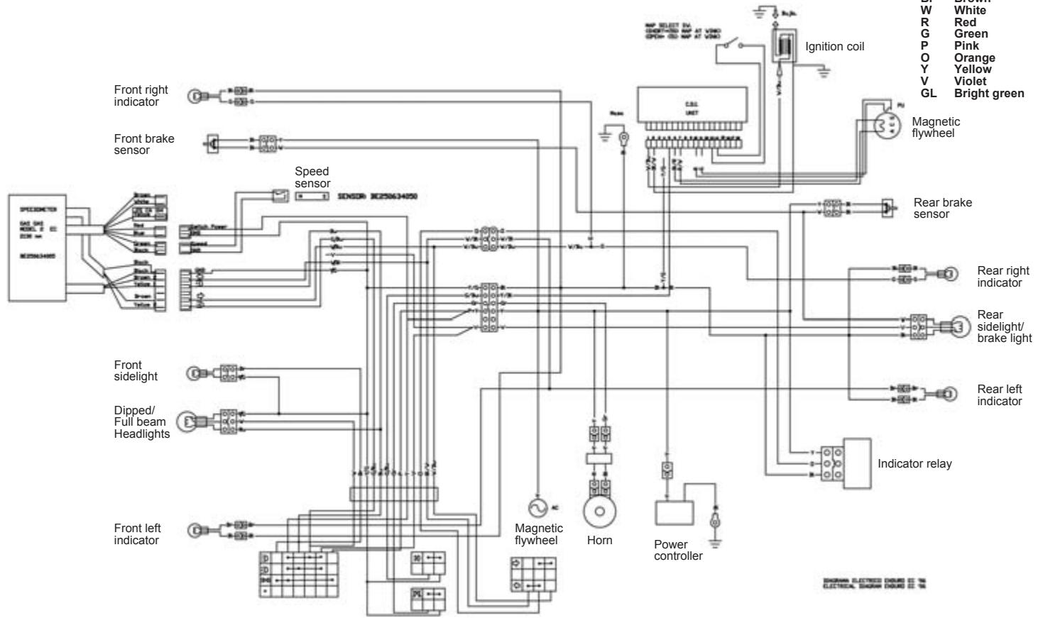
ELECTRIC SCHEMAS
Bl Black
Bu Blue
Gr Grey
Br Brown
W White
Red
G Green
P Pink
0 Orange
Y Yellow
Violet
GL Bright green
WARRANTY TERMS AND CONDITIONS
(According to Law decree 23/2003 on the 10th of July, covering Warranties on Consumer Item Sales)
Warranty terms of the manufacturer GASGAS Motos, S.A.
The company GAS GAS MOTOS, S.A. (hereafter referred to as "GG"), with this present document guarantees the consumer, the purchaser of a vehicle manufactured by GG, that both the materials and the manufacturing are free of defects in accordance with the highest standards of quality. Consequently, GG with this document guarantees the consumer (hereafter referred to as the "purchaser"), in accordance with the conditions set out below, the repair, free of charge, of any defect in materials or that might result from faulty manufacture that is detected in a new motorcycle within the period covered by this Warranty and with no limit on the number of kilometres covered or hours of use.
Warranty Period
The period covered by this Warranty will begin on the day of delivery of the vehicle to the purchaser by a GG authorised dealer, or in the case of demonstration models, on the date in which the vehicle is used for the first time. The seller will be responsible for any unwarranted faults that become apparent within the period established in the Law decree 23/2003 on the 10th of July covering Warranties on Consumer Goods Sold from the time of delivery and in accordance with the Directive 1999/44/EC for other members of the European Community. For countries outside the European Community, the Warranty Period will be determined by the existing regulations in those countries. Nevertheless, should the fault appear during the first six months after the delivery of the motorcycle, it will be presumed that the said fault existed at the time of delivery; from the end of the sixth month onwards, the purchaser must demonstrate that the unwarranted fault existed at the moment of delivery. During the first six months subsequent to the delivery of the repaired vehicle, the seller will be responsible for any unwarranted faults arising out of the repair.
Any defects detected in the product must be brought to the attention of a GG authorised dealer within the Warranty Period. If the last day of this period is a Sunday or an official holiday, the Warranty period will be extended such that the last day of the period covered will be the first working day after the Sunday or official holiday.
Those claims under Warranty for defects not brought to the attention of a GG authorised dealer before the end of the Warranty Period will be excluded.
Obligation of the purchaser
GG will have the right to reject any claims under Warranty in the event that:
a) The purchaser has failed to submit the vehicle to any of the inspections and/or maintenance work required in the Users' Manual, or has exceeded the date set for such inspections or maintenance work. Also excluded from guarantee are those faults that appeared prior to the dates established for an inspection or maintenance work where the latter was not carried out, or was carried out later than the date established.
b) An inspection, maintenance or repair has been performed on the vehicle by third parties not recognised or authorised by GG.
c) Any maintenance or repair has been carried out on the vehicle that violates the technical requirements, specifications and/or instructions indicated by the manufacturer.
d) Spare parts whose use has not been authorised by GG have been used during the course of maintenance work or repairs to the vehicle, or in the event that the vehicle has been used with fuels, lubricants or other liquids (including, amongst others, cleaning products) that have not been expressly mentioned in the specifications set out in the User's Manual. e) The vehicle has been altered or modified in any way or fitted with components other than those expressly authorised by GG as accepted components of the vehicle.
f) The vehicle has been stored or transported in a way that is not in accordance to the corresponding technical requirements.
g) The vehicle has been used for special purposes other than ordinary use, such as competition, races or record breaking attempts.
h) The vehicle has been directly or indirectly damaged as a result of a fall or an accident.
Warranty exclusions
The following items are not covered by this Warranty:
a) Worn parts, including, without any limitation, spark plugs, batteries, petrol filters, oil filter elements, (secondary) chains, engine output pinions, rear sprockets, air filters, brake discs, brake pads, clutch plates and discs, bulbs, fuses, carbon brushes, footrest rubbers, tyres, inner tubes, cables and other rubber components
b) Lubricants (for example, oil, grease, etc.) and working fluids (for example, battery liquid, coolant, etc.)
c) Inspection, adjustments and other maintenance tasks, as well as all kinds of cleaning work
d) Damage to the paint-work and consequent corrosion due to external causes, such as stones, salt, industrial fumes and other environmental impact, or inadequate cleaning with inappropriate products
e) Any damages caused as a result of the defects, as well as any expenses incurred either directly or indirectly as a consequence of the defects (for example, communication costs, accommodation expenses, car hire costs, public transport costs, breakdown truck fees., courier costs, etc.), as well as other financial losses (for example, those caused by the loss of the use of the vehicle, loss of income, time lost, etc.)
f) Any acoustic or aesthetic phenomenon that does not significantly affect the condition or use of the motorcycle (for example, small or hidden imperfections, noise or vibrations that are normal in use, etc.)
g) Phenomena that are the result of the ageing of the vehicle (for example, discolouring of painted or metallic coated surfaces).
Various
1.- GG shall have the prerogative to decide, at its own discretion, whether to repair or replace defective parts. Where parts are replaced, ownership of the parts removed shall pass to GG without any other consideration. The GG authorised dealer, to whom the making good of the defects has been entrusted, is not authorised to make any declarations that are binding on GG.
2. In case of doubt regarding the existence of a defect, or a visual or material inspection is required, GG reserves the right to demand the return of the parts which are the object of a claim under Warranty, or to arrange an inspection of the defect by an expert from GG. Any additional obligations arising out of guarantees on parts replaced free of charge, or any other service rendered free of charge, are excluded from the effects of this present warranty. The Warranty on parts replaced within the Warranty Period will end at the expiry date for the Warranty Period of the product concerned.
3.- Should it prove to be the case that a defect can not be repaired, the purchaser guaranteed shall have the right to the cancellation of the contract (payment of compensation) or a partial refund of the purchase price (discount), instead of repairing the motorcycle.
4.- Any claims against Warranty by the purchaser under the terms of the sale contract with the corresponding authorised dealer shall not be affected by the terms of this present Warranty. Neither will this present Warranty affect those additional contractual rights acquired by the purchaser under the general commercial terms and conditions of the authorised dealer. However, such additional rights may only be exercised through claims against the authorised dealer.
5.- Should the purchaser resell the product within the Warranty Period, the duration and conditions of the present Warranty will remain unaltered, in such a way as that the rights to make claims under the present Warranty in accordance with the terms and conditions set out in this present document shall be transferred to the new owner of the motorcycle.

GASGAS
RECOMIENDA EL USO DE ACEITE:
RECOMMENDSTHEUSEOFOIL:
RECOMMANDE L'USAGE DE L'HUILE:
CONSIGLIA L'USO D'OLIO:
EMPFIEHLT DEN GEBRAUCH VON ÖL:

Global Racing Oil
JULIO / JULY / JUILLET / LUGLIO / JULI 2006