
EC FSE 450 - Off-road motorcycle GAS GAS - Free user manual and instructions
Find the device manual for free EC FSE 450 GAS GAS in PDF.

| Product type | Off-road motorcycle |
| Brand | GAS GAS |
| Model | EC FSE 450 |
| Engine | 4-stroke, single-cylinder, DOHC, liquid cooling, 449 cc |
| Transmission | 6-speed, chain, multi-disc oil-bath clutch |
| Dimensions (L x W x H) | 2135 x 810 x 1260 mm |
| Wheelbase | 1475 mm |
| Ground clearance | 340 mm |
| Dry weight | 119 kg |
| Fuel tank capacity | 9.5 liters |
| Front brakes | 260 mm disc, Nissin dual-piston caliper |
| Rear brakes | 220 mm disc, Nissin dual-piston caliper |
| Front suspension | Marzocchi/WP/Öhlins telescopic fork, 295 mm travel |
| Rear suspension | Mono-shock, 320 mm travel |
| Front tire | 90/90 × 21" |
| Rear tire | 140/80 × 18" |
| Engine oil | 5W50 API SF/SG, 1800 cc |
| Spark plug | NGK CR8E or DENSO U24ESR-N |
| Fuel injection system | Magneti Marelli |
| Coolant capacity | 1.1 L (50/50 water/antifreeze mix) |
| Battery | 12V, maintenance-free, rest voltage >12.6V |
| Front suspension adjustments | Preload, rebound (16 clicks), compression (16 clicks), oil level |
| Rear suspension adjustments | Spring preload, rebound (60 clicks), compression (60 clicks) |
| Maintenance intervals | Oil change every 60 h, air filter after each use, lubricate chain regularly |
Frequently Asked Questions - EC FSE 450 GAS GAS
User questions about EC FSE 450 GAS GAS
0 question about this device. Answer the ones you know or ask your own.
Ask a new question about this device
Download the instructions for your Off-road motorcycle in PDF format for free! Find your manual EC FSE 450 - GAS GAS and take your electronic device back in hand. On this page are published all the documents necessary for the use of your device. EC FSE 450 by GAS GAS.
USER MANUAL EC FSE 450 GAS GAS
Congratulations for choosing this GAS GAS, wich has been developed through GAS GAS, to produce a light weight, high performance machine with superb handling and stability for racing and sporting use.
Your new GAS GAS is a highly tuned production racer for participation in racing events. As with any mechanical device, proper care and maintenance are important for trouble-free operation and top performance. This guide is written to enable you to keep your GAS GAS properly tuned and adjusted.
Due to improvents in design and performance during production, in some cases may be minor discrepancies between the actual vehicle and the illustrations and text in this manual.
Thanks for your confidence and your welcome from GAS GAS motos, S.A.
December 2002
Important notice
Whenever you see the symbols shown below, heed their instructions! Always follow safe operating and maintenance practices.
WARNING
This warning symbol identifies special instructions or procedures which, if not correctly followed, could result in personal injury, or loss of life.
CAUTION
This caution symbol identifies special instructions or procedures which, if noto strictly observed, could result in damage to or destruction of equipment.
IMPORTANT
Off-road motorcycle riding is a wonderful sport, and we hope you will enjoy it to the fullest.
NOTE
This note symbol indicates points of particular interest for more efficient and convenient operation.
However, if improperly conducted, the sport has the potential to cause environmental problems as well as conflicts with other people. Responsible use of your off-road motorcycle will ensure that these problems and conflicts do not occur.
TO PROTECT THE FUTURE OF YOUR SPORT, MAKE SURE YOU USE YOUR BIKE LEGALLY, SHOW CONCERN FOR THE ENVIRONMENT, AND RESPECT THE RIGHTS OF OTHER PEOPLE.
TABLE OF CONTENTS
Foreword. 4
Important notice. 5
Table of contents 6
Specifications. 7
Side stand 11
Recommended fuel. 1 1
Serial number. 12
Start the engine 13
Choke button 14
Shifting gears 14
Stopping the motorcycle 15
Break-in 15
Manitencarchart. 16
Battery 17
Cooling system. 18
Spark plug 21
Clogged air 24
Throttle cable 25
Clutch 26
Exhaust system 26
Drive chain 27
Handlebar 30
Brakes 30
Steering 32
Steering blocade 33
FrontFork. 34
Rear suspension 37
Wheels 39
Lubrication 43
Engine oil 44
Suspension tuning 47
Preparation for competition 53
Storage 54
Gas Gas speedo instructions 54
Troubleshooting 56
Warranty regulations 61
SPECIFICATIONS:
ENGINE
Engine
Displacement in cubic centimeters
Bore and stroke
Spark plug
Injection system
TRANSMISSION
Transmission type Clutch type Driving system Gear Ratio
Primary reduction ratio
Final reduction ratio
Overall drive ratio
Transmission oil
CHASSIS Frame
Tires sizes
Capacity Type
Front Rear
4 cycle, single cylinder DOHC 4r, crank case induction, liquid cooled 399 / 449 c.c.
90 x 62,6 mm. / 95 x 62,6 mm.
NGK CR8E o DENSO U24ESR-N
Magneti Marelli
6 speed
Multidisc in oil bath, hydraulic actuation
Chain
1a 2.071(29/14)
2a 1.625(26/16)
3a 1.333(24/18)
4a 1.100(22/20)
5a 0.913(21/23)
6a 0.791(19/24)
2.85 (57/20)
3.692 (48/13)
8.149 (6th gear)
1800 c.c.
5W50 API SF o SG
DELTABOX type, made of rectangular-section chromoly tube. Aluminium swingarm. 90 / 90 × 21 " 140 / 80 × 18
| Suspension travel | Rear | 295 mm. |
| Rear | 320 mm. | |
| Front fork oil | MARZOCCHI SAE 7.5 WP SAE 5 ÖHLINS SAE 5 - 7.5 | |
| Front fork oil level | Marzocchi: 110 mm. (compressed without spring). WP: 120 mm. (compressed without spring). Öhlns: 110 mm. (compressed without spring). | |
| BRAKES | ||
| Type | Front & rear | Disc brake, Nissin brake pump and Nissin double - piston caliper. |
| Diameter disc | Front | 260 mm. |
| Rear | 220 mm. | |
| DIMENSIONS | ||
| Overall length | 2135 mm. | |
| Overall width | 810 mm. | |
| Overall height | 1260 mm. | |
| Wheel base | 1475 mm. | |
| Ground clearance | 340 mm. | |
| Fuel tank capacity | 9,5 litre (2,4 gallons U.S.) | |
| Height seat | 119 Kg. | |
(Specifications subject to change without notice, which may not be applicable in every country).
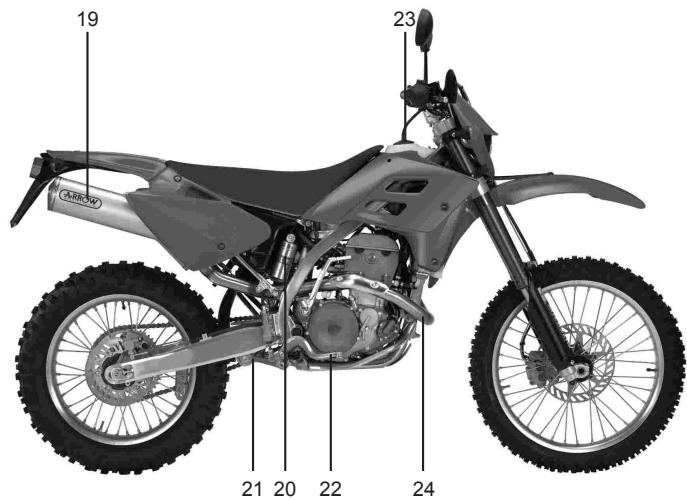
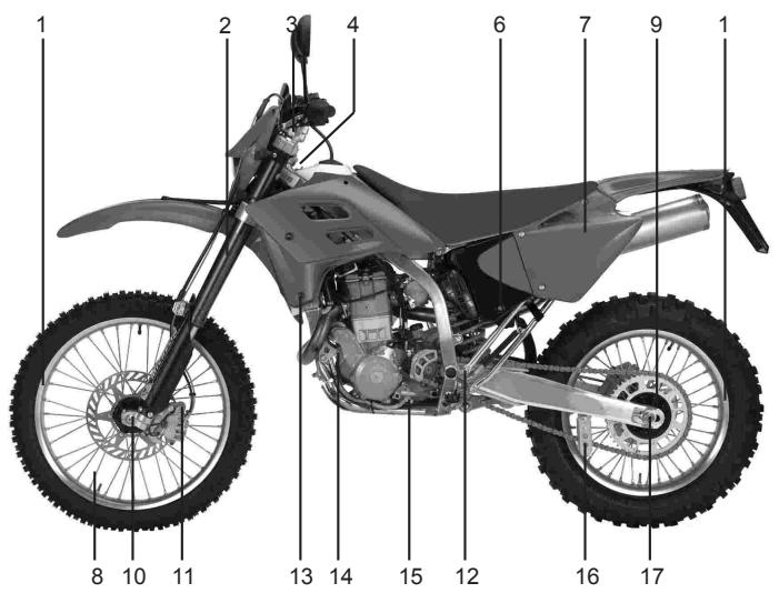
Location of Components
GAS GAS EC FSE 400cc. / 450cc.

1- Clutch lever
2-Engine Stop Button
3-Fuel Tank Fill Cap
4- Front Brake Fluid Reservoir
5- Front Brake lever
6-Throttle Twist-Grip
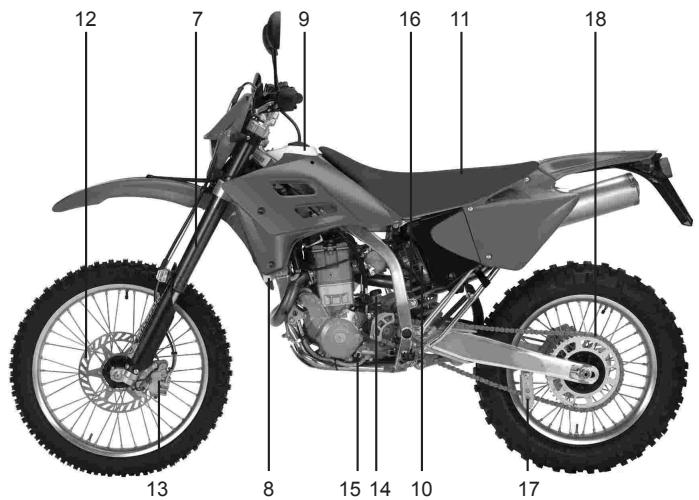
7- Front Suspension
8-Radiator
9-Fuel Tank
10-Air Filter
11-Seat
12- Brake Disc, front
13- Brake Caliper, front
14- Brake Fluid Reservoir, rear
15-Shift Pedal
16-Rear Shock Absorber
17-Chain Guide
18- Drive Chain
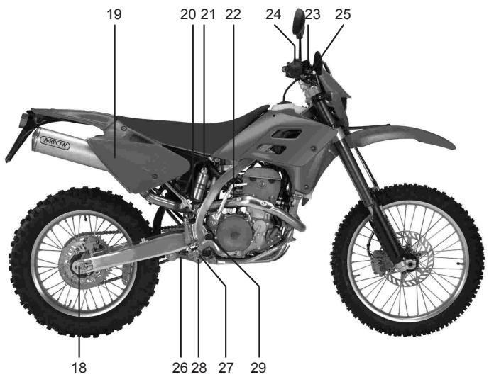
19-Silencer
20-Fuel Tank
21- Connecting Rod o'ring and Swingarm
22- Rear Brake Pedal
23-Oil Dipstick
24- Exhaust
SIDE STAND
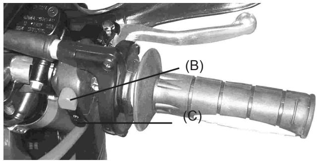
To operate the side stand:
Release the security strap (B), the sidestand is held in the down position by the weight of the motorcycle. Thes sidestand automatically retracts when the motorcycle is placed in the upright position.
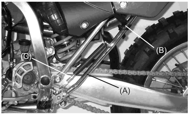
(A). Side Stand
(B). Sidestand spring
(C). Security strap
NOTE
Do not start the engine or ride the motorcycle when the side stand is down. Always engage the security strab (B) before operation of the motorcycle.
FUEL
The GAS GAS FSE 400 cc has a four stroke engine and requires 95 octane, unleaded gasoline
| Gas Tank Capacity | |
| ENDUCROSS FSE | 9,5L |
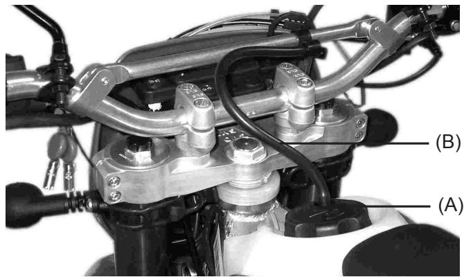
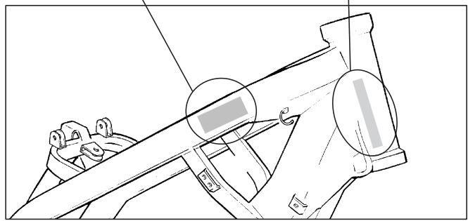
(A). Fuel Cap.
(B). Fuel Vent hose.
Position the vent hose clip in a position which prevents spillage on the steering bearings and the clock.
RECOMENDED FUEL
Use premium gasoline with an octane rating equal to or higher than that shown in the table.
| OCTANE RATING METHOD | MINIUMRATING |
| Antiknock Index (RON+MON)/2 | 90 |
| Research Octane No. (RON) | 98 |
NOTE
If “knocking” or “pinging” occurs, try a different brand of gasoline or higher octane grade.
WARNING
Gasoline is extremely flammable and can be explosive under certain conditions. Always stop the engine and do not smoke. Make sure the area is well ventilated and free from any source of flame or sparks; this includes any appliance with a pilot light.
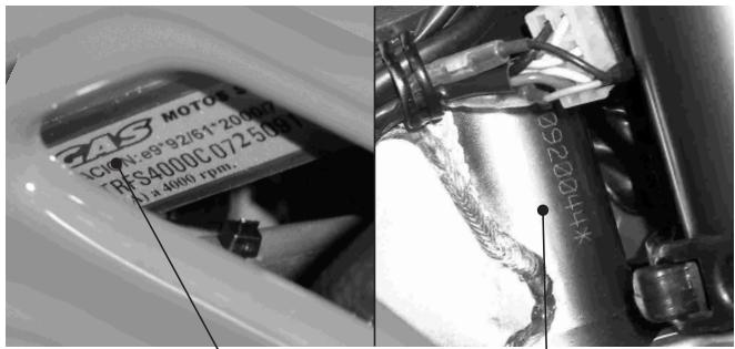
SERIAL NUMBER
This number allows the motorcycle to be registered. The serial number (or V.I.N.) is located on the steering stem of the frame.
Official approval plate
This motorcycle has an official approval plate. It shows the serial number.
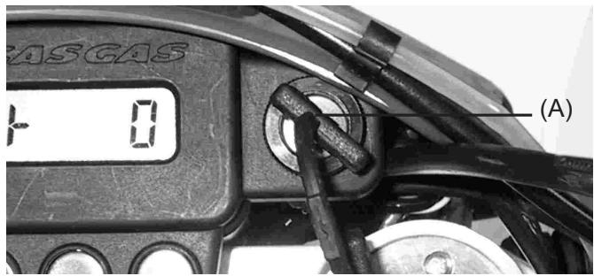
START THE ENGINE
- You have to assure the motorcycle to the neutral position.
- Turn the key in the direction clock (position in "ON" (A)), by this way the electric circuits will be open and then the engine will start. The key will be locked into the contact.
- Without drive the twist grip, swich the electric start button (C).
Stopping the Engine
- Change to the neutral position.
- After racing the engine slightly, close the throttle completely and push the engine stop button(B).
CUIDADO
Stop the engine by the stop button (B). Don't use the key for stop the engine! it can damage the injection system.
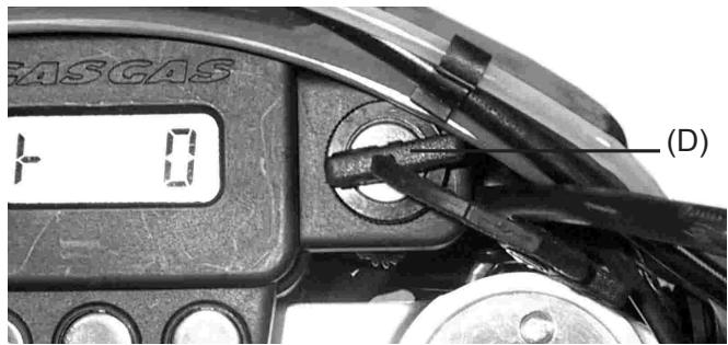
- Switch of the key in the opposite clock direction. The key will be located to the left hand side (D), where all the electric circuits will be closed. The engine will not start. The key can be pulled out of the contact.
- The key can be extract.
NOTA:
Start the engine as soon as the key is turned to the "on" position or the baattery might lose power.
CHOKEBUTTON
The choke button is a mechanism that opens the throttle, without take the twist grip, to favour the engine if it is cold. The engine will get a good temperature in a short time and it won't damage.
For use, pull up the choke knob (A), and without turn the twist grip, start the engine. Look the engine that starts with high revolutions. Waiting few seconds, the engine will be a good temperature.
For pull down the choke button, only drive the twist grip.
NOTA
- If the engine is flooded, kick with the throttle fully open.
- If the clutch lever is pulled, the motorcycle can be started while in any gear.
SHIFTINGGEARS
The transmission is a 6 speed, return shift type with neutral halfway between 1st and 2nd gears. A "return shift" means that to go back to first gear from a higher gear, you must shift back through the gears one by one.
To engage first gear from neutral, pull in the clutch lever and push down on the shift pedal, gently release the clutch lever, then release the shift pedal.
To shift to the next higher gear; pull in the clutch lever, lift the shift pedal with your toe, gently release the clutch lever, and then release the shift pedal.
CAUTION
When changing gears, press firmly on the shift pedal to ensure complete, positive shifting. Careless, incomplete shifts can cause the transmission to jump out of gear and lead to engine damage.
(B). Shift Pedal.
STOPPING THE MOTORCYCLE
For maximum deceleration, close the throttle and apply both front and rear brakes. Disengage the clutch as the motorcycle comes to a stop. Independent use of the front or rear brake may be advantageous under certain conditions.
Downshift progressively as speed is reduced to ensure good engine response when you want to accelerate.
BREAK-IN
To obtain the proper operating clearances in the engine and transmission that are necessary for smooth engine performance and reliability, a brief hour or 20km of operation, run the engine at low and moderate rpm.
NOTE
The slow riding necessary during the break-in period may cause carbon to build up on the spark plug and foul it. If inspection of the spark plug shows this to be the case, replace the standard spark plug with a hotter spark plug for the duration of the b in period.
- Start the engine and let it run at idle until the engine is thoroughly warmed up.
- Stop and let the engine cool completely.
- Start the engine and ride for 10 minutes at moderate speed - NEVER ACCELERATE HARD.
- Stop and let the engine cool completely. Be sure to check and adjust chain slack and spoke tightness and make a general inspection.
- Start the engine and ride for 20 minutes at moderate speed. - NEVER ACCELERATE HARD.
- Stop and let the engine cool completely. Check and adjust as step. Then drain the coolant, remove the cylinder head, cylinder and piston, and inspect these parts.
- Install the parts removed.
- Fill the radiator up to the bottom of the radiator filler, bleed the air from the cooling system.
- Start the engine and ride for 30 minutes at moderate speed - NEVER ACCELERATE HARD.
- Stop and let the engine cool completely, check and adjust.
- After the break-in procedure has been properly carried out, the motorcycle is ready for regular operation.
CAUTION
However, since recklessly high r/min (rpm) will lead to engine trouble, take care to use the necessary skill and technique in operating the motorcycle.
NOTE
After break-in, install a new standard spark plug, and change the transmission oil.
| MAINTENANCE CHART | |||
| Part | PeriodFirst 5 hours | PeriodEvery 30 hours | PeriodEvery 60 hours |
| Air filter | Inspect every time the bike has been running and has been checked | ||
| *Muffler boltsand connections | T | T | T |
| *Valve tolerance | I | - | I |
| Spark plug | - | I | R |
| Injection pump pipes | I | I*Check every 4 years | I |
| Motor oil and filter oil | R | R | R |
| *Oil motor pipes | I | I | I |
| Coolant Fluid | - | ICheck every 2 years | I |
| Radiator pipes | I | I | I |
| Clutch | I | I | I |
| Chain | Clean, lubricate and inspect every time it runs | ||
| *Brakes | I | I | I |
| Brake pipes | I | I*Chec every 4 years | I |
| Brake fluid | I | I*Chec every 2 years | I |
| Tires | Inspect tire pressure and possible damages caused every time the bike runs | ||
| *Steering play | I | - | I |
| *Front fork | I | - | I |
| *Rear suspension | I | - | I |
| *Nuts and bolts in the frame | T | T | T |
NOTE: I = Inspect and clean, adjust, substitute or lubricate if it's necessary; R = Replace, T = Tighten, C = Cleaning
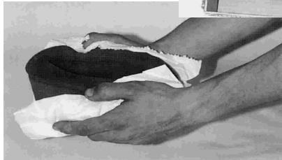
BATTERY
This battery is maintenance free and checking the fluid level is not required. It is recommended to check the charge of the battery periodically.
To remove the battery, follow these steps :
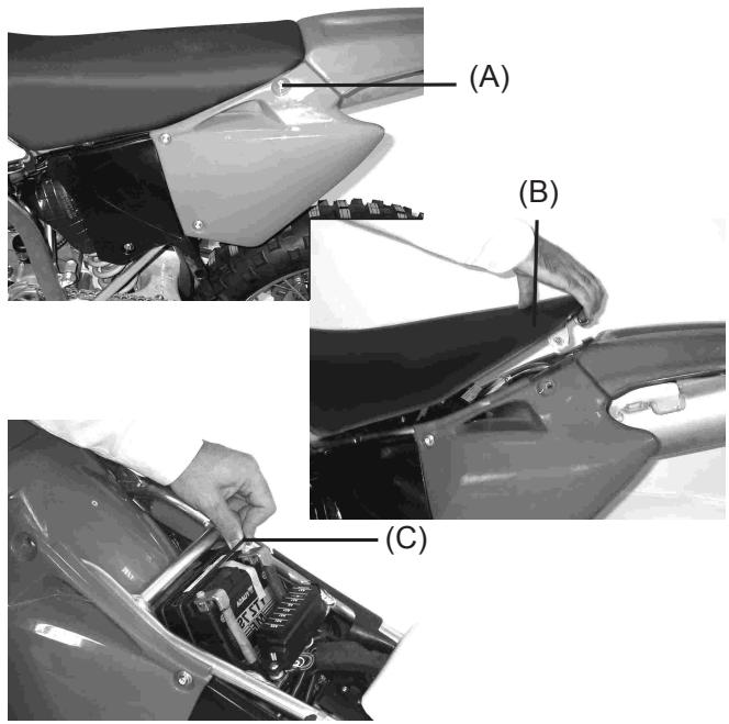
- Remove the screws (A) and the seat (B)
- Pull the rubber (C) and remove the battery
WARNING
Hydrogen gas produced by the battery may explode if exposed to open flame or sparks. Keep flames and sparks away from the battery.
The operating instructions for the battery are as follows:
- Check the battery tension while the circuit is open.
- In case the battery's tension is below 12.60V , or if the storage period has exceeded 6 months, the battery has to be recharged following the instructions in paragraph. In case the tension is above 12.60V , the battery can be installed on the vehicle without having to recharge it.
3.1. Charge mode with constant tension.
- Constant tension = 14.40 - 14.70V
- Initial charging power = 0.1 - 0.5Cn
- Charge duration = 6 hours minimum / 24 hours maximum.
3.2. Charge mode with constant power.
-
Maximum charge power = 0.1 Cn.
-
Recommended charging time = 5 - 8 hours.
- The product of (charging power) x (charging time) has to stay within the range:0,5 - 0,8 Cn.
NOTE
In case charging modes different than the established ones are used, by no means, may the maximum allowed power or the charging time of 24 hours be surpassed.
CAUTION
| Exceeding charge standards may reduce the life cycle of the battery. |
| Never surpass charge standards. |
CAUTION
| Inverting the polarity of the battery terminals may cause battery charge problems and cause damage to it. The red terminal is the positive (+) and the black terminal is the negative (-). |
COOLING SYSTEM
Radiator Hoses
Check the radiator hoses for cracks or deterioration, and connections for looseness in accordance with the Periodic Maintenance Chart.
Radiator
Check the radiator fins for obstruction by insects or mud. Clean off any obstructions with a stream of lowpressure water.
CAUTION
| Using high-pressure water, as from a car wash facility, could damage the radiator fins and impair the radiator's effectiveness. |
| Do not obstruct or deflect airflow through the radiator by installing unauthorized accessories in front of the radiator. |
| Interference with the radiator airflow can lead to overheating and consequent engine damage. |
Coolant
Coolant absorbs excessive heat from the engine and transfers it to the air at the radiator. If the coolant level becomes low, the engine overheats and may suffer severe damage. Check the coolant level each day before riding the motorcycle. Replenish coolant if the level is low.
WARNING
To avoid burns, do not remove the radiator cap or try to change the coolant when the engine is still hot. Wait until it cools down.
Coolant information
To protect the cooling system aluminum parts (engine and radiator) from rust and corrosion, the use for corrosion and rust inhibitor chemicals in the coolant is essential. If coolant containing corrosion and rust inhibitor chemicals is not used, over a period of time, the cooling system accumulates rust and scale in the water jacket and radiator. This will clog coolant passages, and reduce the efficiency of the cooling system.
CAUTION
Use of incorrect coolant solutions will cause severe engine and cooling system damage.
Use coolant containing corrosion inhibitors made specifically for aluminum engines and radiators in accordance with the instructions of the manufacturer.
WARNING
Coolant chemicals are harmful to the human body. Follow coolant manufacturer warnings and coolant handling instructions.
CAUTION
Soft or distilled water must be used with the inhibitor chemicals and the antifreeze (see below for antifreeze) in the cooling system. If hard water is used in the system, it causes scale accumulation in the water passages, and considerably reduces the efficiency of the cooling system.
If the lowest ambient temperature encountered falls below the freezing point of water, protect the cooling system against engine and radiator freeze-up. Use a permanent type of anti-freeze (soft water and ethylene glycol plus corrosion and rust inhibitor chemicals for aluminium engines and radiators) in the cooling system.
For the coolant mixture ratio under extreme conditions, choose the mixture ratio listed on the container for the lowest ambient temperature.
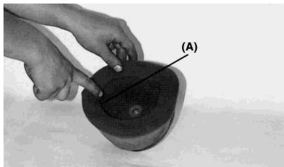
Coolant Level
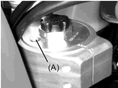
- Situate the motorcycle so that it is perpendicular to the ground.
- Remove the radiator cap in two steps. First turn the cap counterclockwise to the first stop and wait there for a few seconds. Then push and turn it further in the same direction and remove the cap.
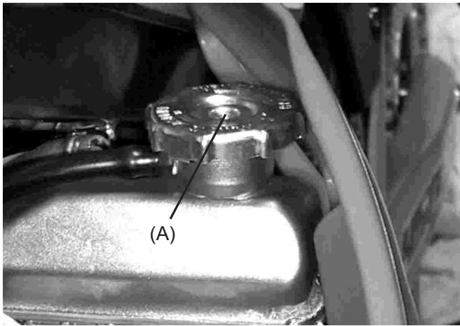
(A). Radiator Cap
CAUTION
Permanent types of antifreeze on the market have anticorrosion and anti-rust properties. When it is diluted excessively, it loses its antifreeze and anticorrosion properties. Dilute a permanent type of antifreeze in accordance with the instructions of manufacturer.
NOTE
Check the level when the engine is cold.
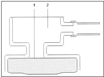
(1). Coolant Level
(2).Breather Hose
If the coolant level is low, add the correct amount of coolant through the filler opening.
Recommended Coolant
Permanent type of antifreeze (soft water and ethylene glycol plus corrosion and rust inhibitor chemicals for aluminum engines and radiators).
NOTE
A permanent type of antifreeze is installed in the cooling system when shipped. It is colored green, contains a 50% solution of ethylene glycol, and has a freezing point of -35^ . (-32^) (USA).
Water and coolant mixture ratio
1:1 (Water 50%, Coolant 50%)
Total Amount: 1.1 L.Capacidad: 1.1 L.
Coolant Change
- The coolant should be changed periodically to ensure long engine life.
- Wait for the engine to cool completely.
- Situate the motorcycle so that it is perpendicular to the ground. -
- Remove the radiator cap.
- Place a container under the coolant drain plug, and drain the coolant from the radiator and engine by removing the drain plug at the bottom of the water pump cover. Immediately wipe or wash off any coolant that spills on the frame, engine, or wheels.
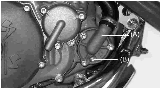
(A). Water Pump Cover
(B). Drain Plug
WARNING
Coolant on tires will make them slippery and can cause an accident and injury.
-
Visually inspect the old coolant. If whitish cotton-like wafts are observed, aluminum parts in the cooling system are corroded. If the coolant is brown, iron or steel parts are rusting. In either case, flush the cooling system.
-
Check the cooling system for damage, loose joints, or leaks.
- Install the water pump cover drain plug and cylinder drain plug with the specified torques shown in the table. Always replace the gasket with a new one, if it damaged.
Drain Plug Tightening Torque Water Pump Cover Plug: 9 Nm. (6FT.LBS).
- Fill the radiator up to the bottom of the radiator filler neck with coolant, and install the radiator cap.
- Check the cooling system for leaks.
- Start the engine, warm up the engine thoroughly, then stop the engine.
- Check the coolant level after the engine cools down. Add coolant up to the bottom of the radiator filler neck.
SPARK PLUG
The standard spark plug is a shown in the table, it should have a specified gap, and be tightened to 27 N-m. (20FT.LBS).
Standard Spark Plug
NGK CR8 E
0.7-0.8 mm.
The spark plug should be taken out periodically to check its gap and ceramic insulator. If the plug is oily or has carbon build up on
it, clean it (preferably with a (sandblaster) and then clean off any abrasive particles. The plug may also be cleaned using a high flashpoint solvent and a wire brush or other suitable tool. Measure the gap with a wire-type thickness gauge, and adjust the gap, if incorrect, by bending the outer electrode. If the spark plug electrodes are corroded or damaged, or if insulator is cracked, replace the plug.
NOTE
Inspect every 30 hours. Replace every 60 hours.
To find out whether the right temperature plug is being used, pull it out and examine the ceramic insulator around the center electrode. If the ceramic is light brown, the spark plug is correctly matched to engine temperature. If the ceramic is burned whit, the plug should be replaced with the next colder plug. If the ceramic is black, the plug should be replaced with the next hotter plug.
NOTE
If the engine output decreases, replace the spark plug to regain performance.
Spark Plug maintenance
| NGK | DENSO | COMMENTS |
| CR7E | U22ESR-N | If the standard plug looks wet or has a dark color, replace. |
| CR8E | U24ESR-N | Standar |
| CR9E | U27ESR-N | If the standard plug looks glassy or has a white color, replace the plug. |
CAUTION
Incorrect installation of the plug or an incorrect heat range choice may cause extensive engine damage, and such damage would not be covered by the warranty.
Use always manufacturer-recommended spark plugs. Consult your dealer or a qualified mechanic in order to know which is the best plug for your motorcycle.
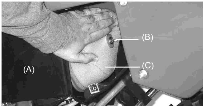
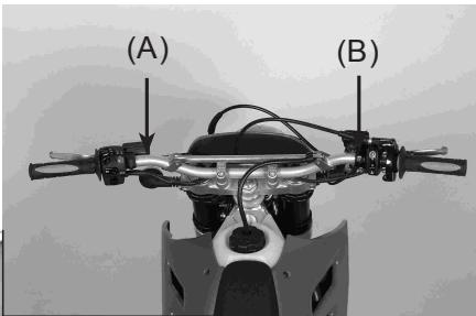
Extract the spark plug
To remove the spark plug, follow the following steps:
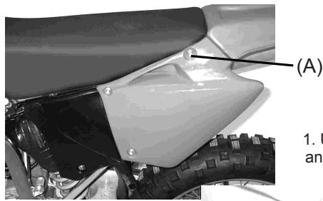
1. Unscrew screws (A) and (B) (right and left)
(B)
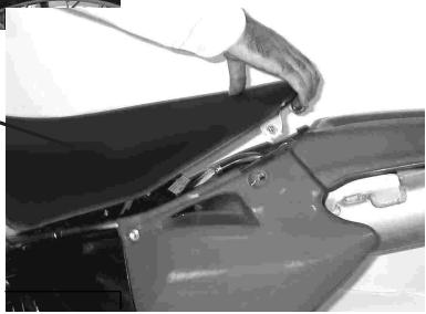
2. Remove the seat.
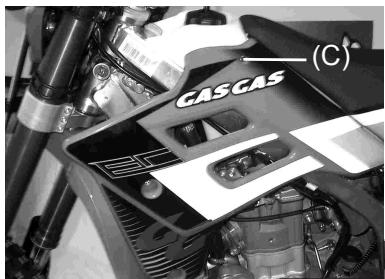
3. Unscrew screws (C) (right and left).
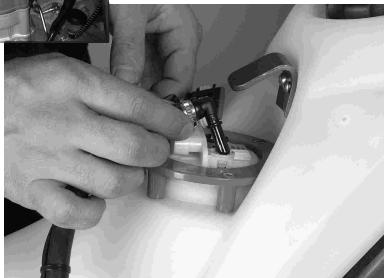
4. Disconnect the pump cables (caution: the tubes contain gasoline).
WARNING
When the injection pump pipes are removed, gasoline may be spilled and cause a fire.
Stop the engine before removing the tank. Keep flames and sparks away from the gas cap. Do not smoke.
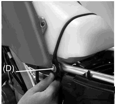
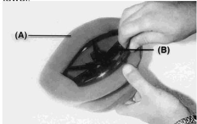
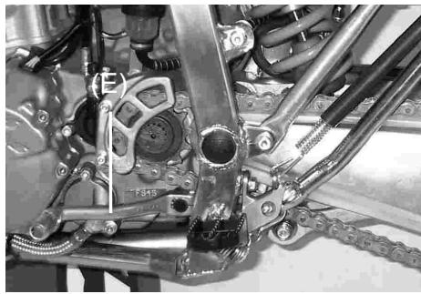
5. Remove the tank rubber (D).
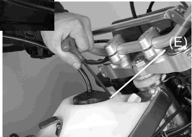
6. Unscrew screw of fuel tank (E).
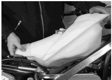
7. Extract the fuel tank.
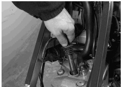
8. Extract the protector cap.
NOTE:
for the correct use of the plug, it is protected by a cap. Keep the cap clean and dry.
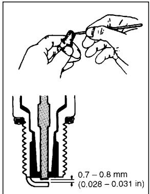
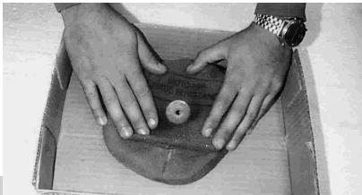
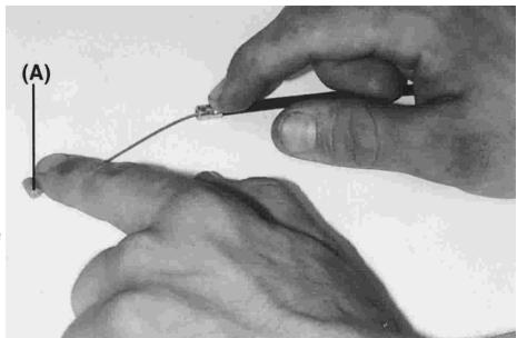
- Extract de plug and remove the carbon deposits from the spark plug with a small tip or a metallic brush. Readjust the gap in the plug between 0.7 and 0.8mm (0.028 - 0.031 in.). Before removing the carbon deposits, check its color; this color tells us whether the standard plug is the best for our use.
CLOGGED AIR
A clogged air cleaner restricts the engine's air intake, increasing fuel consumption, reducing engine power, and causing spark plug fouling.
WARNING
A clogged air cleaner may allow dirt and dust to enter the carburetor and stick the throttle open. This could cause an accident.
CAUTION
A clogged air cleaner may allow dirt and dust to enter the engine causing excessive wear and possible engine damage.
Inspect the element, without fail, before and after each racing or practice session. Clean it if necessary.
Air cleaner
WARNING
Clean the element in a well-ventilated area, and take care that there are no sparks or flame anywhere near the working area; this includes any appliance with a pilot light. Do not use gasoline or a low flashpoint solvent to clean the element. A fire or explosion colud result.
- Remove the filter cover (A)
-
Remove the wing bolt (B) and pull out the element (C).
-
Stuff a clean, lint-free towel into the carburetor so no dirt is allowed to enter the carburetor.
CAUTION
Do not spin the filter on its cage. It is possible to tear or damage the filter.
- Wipe out the inside of the air cleaner housing with a clean damp towel.
-
Take the support cage (B) off the frame (A).
-
Clean the element in a bath of a filter cleaning fluid using a soft bristle brush.
-
Squeeze it dry in a clean towel. Do not wring the element or blow it dry; the element can be damaged.
-
Inspect the element for damage such as tears, hardening, or shrinkage. If damaged, replace it or it will allow dirt into the carburetor.
-
Apply grease to all connections and srew hole in the air cleaner housing and intake tract.
-
Install the element in the machine, and make sure the sealing surface of the element is seated properly.
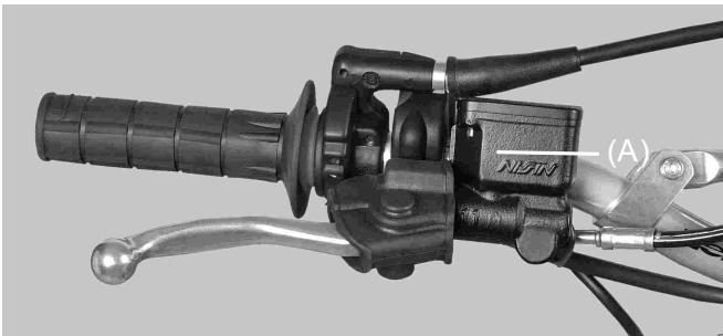
THROTLLE CABLE
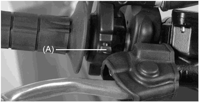
- Inspect the throttle grip for smooth operation in all steering positions. In accordance with the Periodic Maintenance Chart, check and adjust the throttle cable.
- Check that the throttle grip has 2 - 3mm of play and turns smoothly.
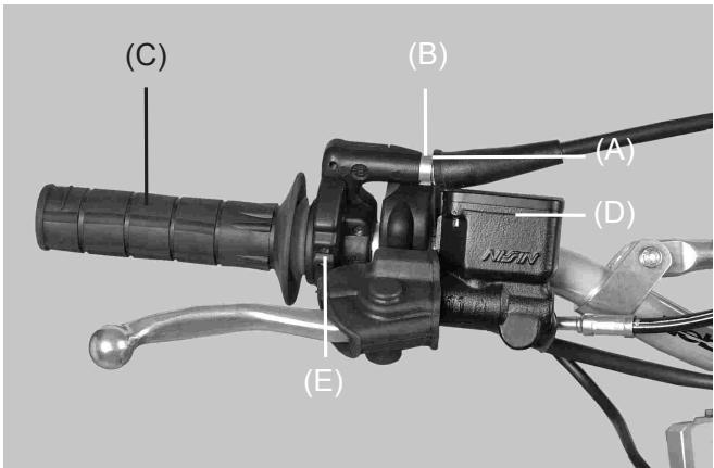
(A). Adjuster.
(B). Locknut.
(C). Throttle grip.
(D). Brake fluid reservoir, rear.
(E).Choke Button.
- If the play is incorrect, loosen the locknut on the upper end of the throttle cable, and turn the adjuster to obtain the correct amount of play. Tighten the locknut.
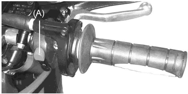
CLUTCH
Proper clutch lever play between the clutch lever and the clutch lever holder is 2-3 mm.
When there is too much lever play, first try adjusting the clutch lever.
Loosen the knurled locknut, turn the adjuster to obtain the proper amount of lever play, and tighten the locknut.
(A). Clutch Lever.
(B). Knurled Locknut.
(C). Hydraulic fluid tank.
EXHAUST SYSTEM
The muffler and silencer reduce exhaust noise and conduct the exhaust gases back away from the rider.
If the muffler is badly damaged, dented, cracked or rusted, replace it with a new one. Replace the silencer packing. If the exhaust noise becomes too loud or the engine performance drops.
Silencer Packing Change
- Remove the right side.
- Remove the silencer mounting bolts and pull the silencer off toward the rear.
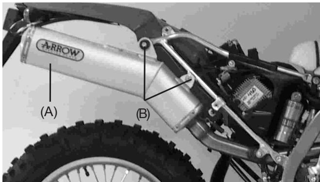
(A).Silencer.
(B). Mounting bolts.
- Remove the inner pipe mounting rivots (A), and pull out the inner pipe (B).
- Pull off the old silencer packing, and install the new silencer packing.
- Install the inner pipe into the silencer.
- Install the silencer and right side cover.
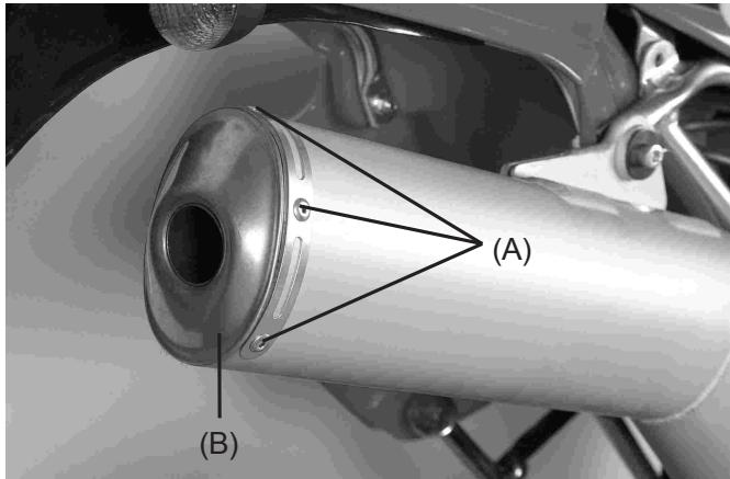
(A).Rivots
(B). Inner Pipe
DRIVE CHAIN
The drive chain must be checked, adjusted, and lubricated in accordance with the Periodic Maintenance table. If the chain becomes badly worn or maladjusted either too loose or too tight the chain could jump off the sprockets or break.
WARNING
A chain that breaks or jumps off the sprockets could snag on the engine sprocket or lock the rear wheel, severely damaging the motorcycle and causing it to go out of control.
Slack Inspection
The space between the chain and the swing arm at the rear of the chain slider should be 30-50 mm. Rotate the rear wheel to find the place where the chain is tightest (because it wears unevenly). Adjust the drive chain if it has too much or too little slack.
NOTE
In wet and muddy conditions, mud sticks to the chain and sprockets resulting in an overly tight chain, and the chain may break. To prevent this, adjust the chain to 30-50 mm. of space between the chain and swing arm whenever necessary.
In addition to checking the slack, rotate the rear wheel to inspect the drive chain and sprockets for damaged rollers, loose pin and links, unevenly or excessively worn teet, and damaged teeth.
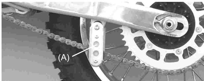
Slack Adjustment
- Loosen the rear axle nut and both chain adjuster locknuts.
- Turn the nuts on the chain adjusting bolts evenly until the drive chain has 30 - 50mm of space between the chain and the swing arm. To keep the chain and wheel aligned, the notch on the left chain adjuster should align with the same swing arm mark that the on the right chain adjuster aligns with.
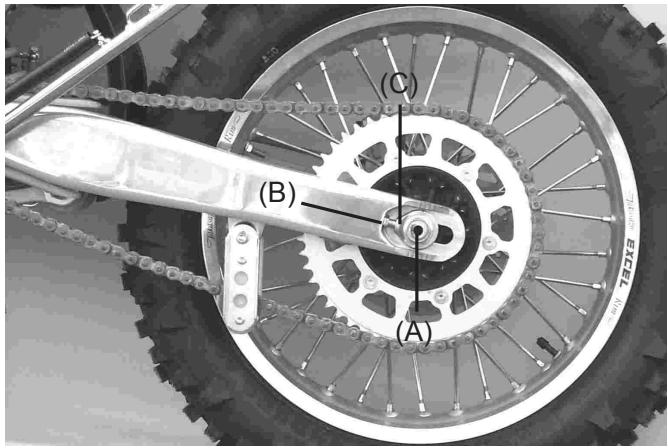
(A). Axle.
(B). Adjusting nut.
(C). Adjustment bolt.
NOTE
Wheel alignment can also be checked using the straightedge or string metod.
WARNING
Misalignment of the wheel will result in abnormal wear and may result in an unsafe riding condition.
- Tighten the axle nut to 98 N-m. (70ft-lbs).
- Tighten both chain adjuster locknuts.
- Rotate the wheel, measure the chain slack again at the tightest position, and readjust if necessary.
WARNING
If the axle nut is not securely tightened an unsafe riding condition may result.
Drive Chain, Chain Guide, Chain Slidder, and Sprockets Wear Inspection.
When the chain has worn so much that it is more than 2% longer than when new, it is no longer safe for use and should be replaced. Whenever the chain is replaced, inspect both the engine and rear sprockets, and replace them if necessary. Worn sprockets will cause a new chain to wear quickly.
NOTA:
For maximum stretch resistance and safety, a genuine part must be used for replacement.
To minimize any chance of the master link coming apart, the master link clip must be installed with the closed end of the «U» points in the direction of chain rotation.
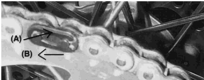
(A).Clip.
(B). Direction of Chain Rotation.
Chain Guide Wear
Visually inspect the drive chain guide. If the guide is worn excessively or damaged, replace it.
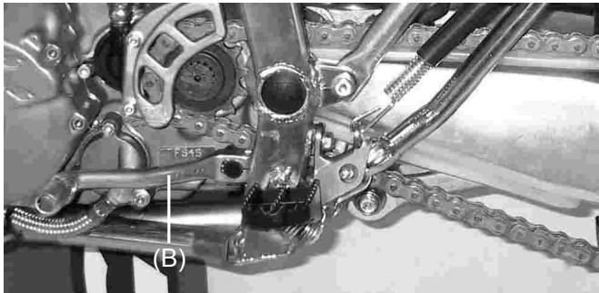
Chain Slider Wear
Visually inspect the upper and lower chain sliders.
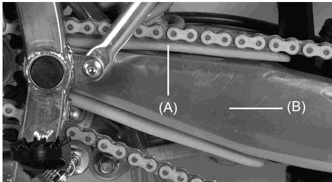
(A). Chain Slider
(B). Swing Arm
Sprocket Wear
Visually inspect the sprocket teeth. If they are worn or damaged, replace the sprockets.
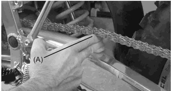
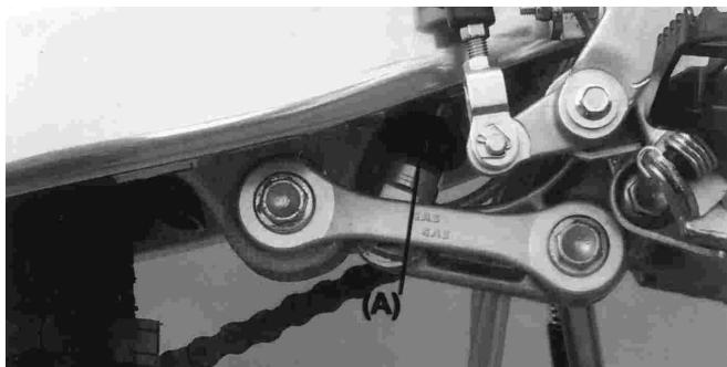
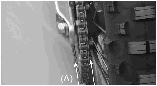
Lubrication
Lubrication is necessary after riding through rain or in the mud, or any time that the chain appears dry. A heavy oil is preferred to a lighter oil because it will stay on the chain longer and provide better lubrication.
Apply oil to the side of the rollers so that it will penetrate to the rollers and bushings. Wipe off any excess oil.
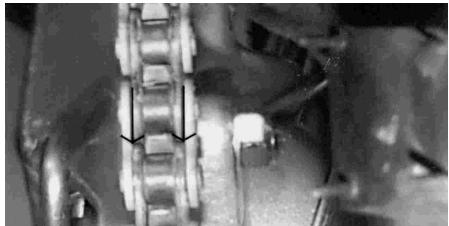
(A). Apply oil
HANDLEBAR
To suit various riding positions, the handlebar position can be adjusted front to rear.
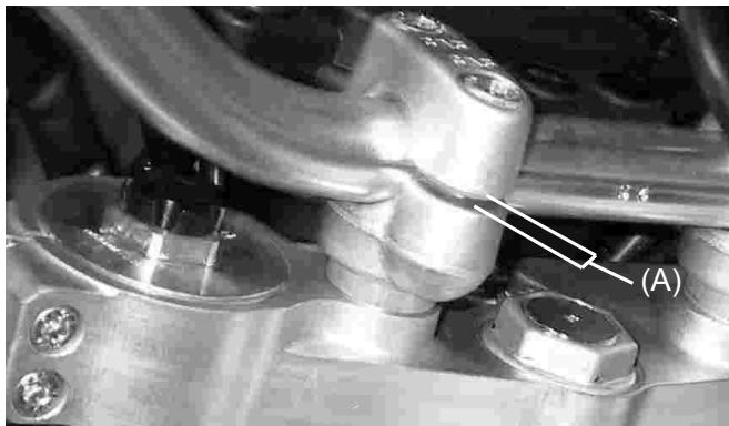
Handlebar Position Adjustment
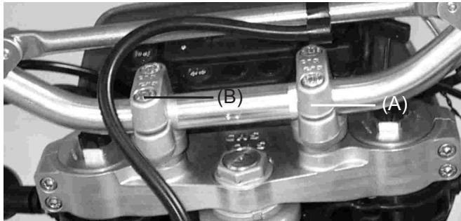
Loosen the handlebar holder nuts (B), turn about the handlebar holder (A), and tighten the nuts securely.
Tighten the clamp bolts, front first and then the rear, to 25Nm of torque (18 ft.lbs). If the handlebar clamp is correctly installed, there will be an even gap at the front and rear after tightening (A).
BRAKES
Disc and disc pad wear is automatically compensated for and has no effect on the brake lever or pedal action. So there are no parts that require adjustment on the brakes except brake lever play and brake pedal position.
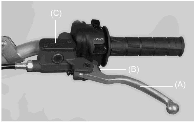
Front Brake Lever Play
Adjust the front brake lever (A) to suit you. To adjust the brake lever play, loosen the locknut and turn the adjuster (B) to either side. After adjustment, tighten the locknut securely. Then check the brake for good braking power and no brake drag.
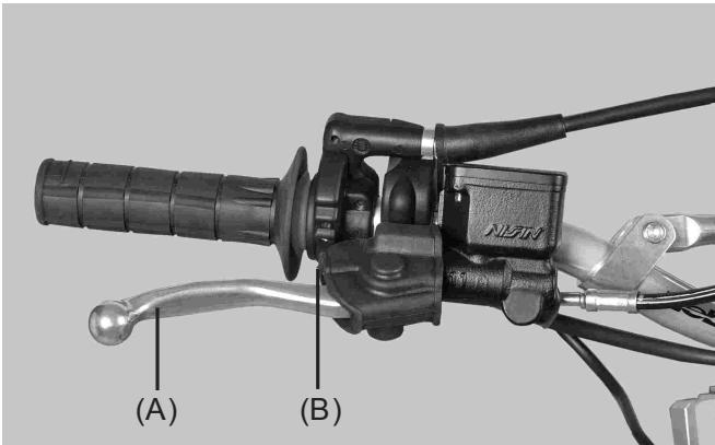
(A). Brake Lever
(B). Adjuster
Rear Brake Pedal Position
When the brake pedal is in rest position, there should be a play of 10mm . If not, adjust the pedal position.
The brake pedal has 10 - 20mm of play when the pedal is pushed down lightly by hand.
- To adjust the pedal play, loosen the locknut and turn the adjuster.
- After adjustment, tighten the locknut securely.
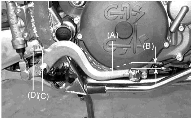
(A). Rear Brake pedal
(B). 10mm play
(C). Adjusting Bolt
(D). Locknut
WARNING
If the brake lever or pedal feels mushy when it is applied, there might be air in the brake lines or the brake may be defective. Since it is dangerous to operate the motorcycle under such conditions, have the brake checked immediately.
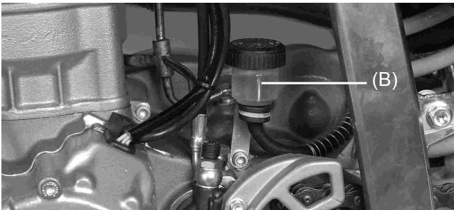
Disc Brake Fluid
In accordance with the Periodic Maintenance Chart, inspect the brake fluid level in the reservoir and change the brake fluid. The brake fluid should also be changed if it becomes contaminated with dirt or water.
Disc Brake Fluid
Use D.O.T.3 D.O.T.4.
Fluid Level Inspection
The front (A) and rear (B) reservoirs must be kept more than half full with brake fluid. If the amount of brake fluid is insufficient, add brake fluid.
CAUTION
Do not spill brake fluid onto any painted surface. Do not use fluid from a container that has been left open or that has been unsealed for a long time. Check for fluid leakage around the fittings. Check for brake hose damage.
WARNING
Do not mix two brands of fluid. Change the brake fluid in the brake line completely if the brake fluid must be refilled with a type other than the brake fluid already in the reservoirs.
Brake Wear Inspection
In accordance with the Periodic Maintenance Chart, inspect the brakes for wear. For each front and rear disc brake caliper. If the thickness of either pad is less than 1mm , replace both pads in the caliper as a set Pad replacement should be done by an authorized GAS GAS dealer.
STEERING
The steering should always be kept adjusted so that the handlebar will turn freely but have no excessive play.
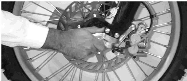
To check the steering adjustment, using a stand under the frame, raise the wheel off the ground. Push the handlebar lightly to either side; if it continues moving under its own momentum, the steering is not too light. Squatting in front of the motorcycle, grasp the lower ends of the front fork at the axle, and push and pull the bottom end of the front fork back and forth; if play is felt, the steering is too loose.
If the steering needs adjustment
- Using the stand under the frame, stabilize the motorcycle.
- Place a stand or block under the engine to raise the front wheel off the ground.
- Remove the handlebar (A).
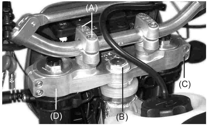
- Loosen the front fork upper clamp bolts, and remove the steering head nut and washer, and take off the steering stem head (B).
- Turn the steering stem locknut with the stem nut wrench to obtain the proper adjustment (C).
-
Install the stem head (D).
-
Tighten the steering stem head nut, and front fork upper or lower clamp bolts to the specified torque (A).
Stem Head Nut: 44 N-m (4.5 Kg-m)
Upper Fork Clamp Bolts: 22 N-m (2.25 Kg-m)
- Check the steering again, and readjust if necessary.
- Install the removed parts.
STEERING BLOCADE
This mechanism (A) allows us to blockade the steering. Is placed on pipe steering.
You have to turn right the handlebar, pull in the key, turn left the key, push, turn right and pull out the key.
(A). Steering blocade
CAUTION
Never forget the key in the lock. If you turn left the steering with the key in, it will be damaged.
FRONT FORK
The front fork should always be adjusted for the rider's weight and track conditions by using one or more of the following methods.
-
Air pressure: Air pressure acts as a progressive spring and affects the entire range of fork travel. The air pressure in the fork increases as the fork heats up, so the fork action on your GAS GAS will get stiffer as the race progresses. Because of this, we don't recommend using air pressure for additional springing. Your GAS GAS forks are designed to work without adding any air.
-
Rebound and compression dampening adjustment: This adjustment affects how quickly the rebound. The fork rebound dampening adjuster has 16 clicks. The seated position (fully clockwise until the adjuster stops) is full hard. From the point 6 - 8 clicks counterclockwise is the standar setting, and 16 clicks counterclockwise is full soft.
-
Oil level adjustment: The effects of higher or lower fork oil level are only felt during the final 100mm of fork travel. A higher oil level will make the fork rebound more slowly.
-
Fork springs: Optional springs are available that are softer and stiffer than standard.
Air Pressure
The standard air pressure in the front fork legs is atmospheric pressure. The air pressure in the fork legs increases as operation progresses.
- Using the stand under the frame, stabilize the motorcycle.
- Place a stand or block under the engine so that the front wheel is raised off the ground.
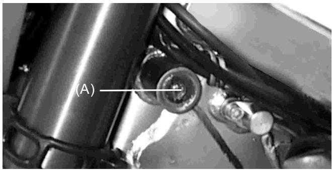
- Remove the screws at the top of the front fork top bolts to let the air pressure equalize. Then replace them.
(A). Screw air purge
Rebound Dampening Adjustment
- To adjust turn the knob located at the top of the fork.
- Adjust to rider preference.
(A). Adjuster knobs
CAUTION
The left and right fork tubes must bealigned (level) at the top clamps. (see the illustration).
Compression Dampening Adjustment
- To adjust, turn the knob located at the top of the fork. Adjust to rider preference.
Oil level Adjustment
- Using the stand under the frame, stabilize the motorcycle.
- Place a stand or block under the engine so that the front wheel is raised off the ground.
- Remove the front fender and front disc cover.
- Unbolt the brake hose holder mounting bolts.
- Remove the front fork protectors.
- Remove the handlebar clamp bolts and remove the handlebar.
- Remove the top clamps of the forklegs.
- Let the forks completely compress.
- Raise the fork springs from the fork.
- Grasp the top casps and loosen the click nuts on the caps.
- Remove the caps from the fork legs.
- Remove the fork springs.
- Put the oil level gauge on the top of the fork tube, and measure the distance from the top of the fork tube to the oil level.
Stand Oil Level
Marzocchi: 110 mm
WP: 120 mm
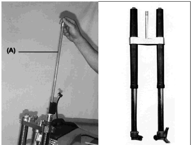
(A). Draining Oil
(B). Filling Oil
Adjust the oil level as required within the adjustable range using the following oil:
MARZOCCHI SAE 7'5
WP. SAE 5
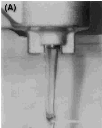
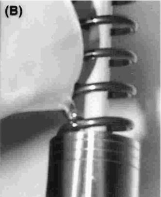
(A).Push Rod
- Pull up the push rod (A) slowly.
- At this time, the fork oil comes out of the push rod hole, let it overflow until it stops.
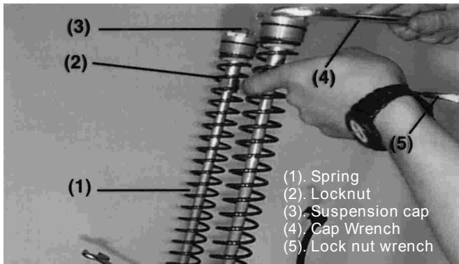
- Put the fork spring (1) into the fork tube.
- Pull down the fork spring and insert the spring holder (5) (special tool) under the push rod nut or piston holder.
- Install the top cap bolt (3) on the top of the fork tube and tighten it to 29 N-m. (21 ft.lbs).
- Repeat on other fork.
- Install removed parts.
Fork Springs
Different fork springs are available to achieve suitable front fork action in accordance with the rider's weight and track conditions.
- Harder springs make the fork stiffer, and rebound action quicker.
- Softer sprigs make the fork softer, and rebound action slower.
Fork Clamp Position Adjustment
Steering qualities are greatly affected by the fork clamp position (the amount of the outer tube projecting above the steering stem head). When the fork tube height is smaller, the front end becomes lighter due to change in weight bias. Also, it tends to understeer in turns at «whash out». When the height is greater, the results are opposite. Be sure the front tire doesn't rub the fender when the fork tubes compress fully. Make this adjustment in 5mm increments.
| CAUTION |
| The outer tubes, both right and left, should be adjusted evenly. |
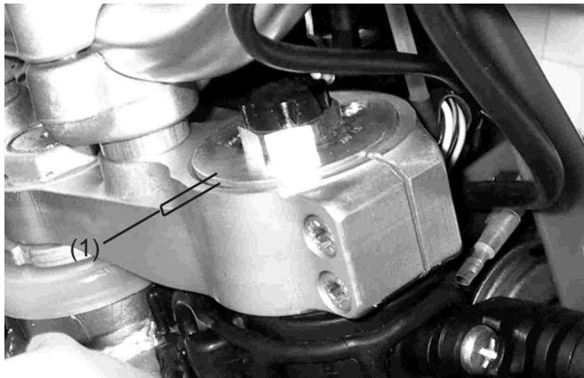
(1).Fork tube height
REAR SUSPENSION
The rear suspension system of this motorcycle is single shock. It consist of a rear shock absorber, swing arm, tie rods and rocker arm.
In general the operating characteristics of the single shock are similar to the front fork. But, in achieving progressive spring characteristics a linkage system is used.
To suit various riding conditions, the spring preload of the shock absorber can be adjusted or the spring can be replaced with an optional one. Also the dampening force can be adjusted easily so changing oil viscosity is unnecessary.
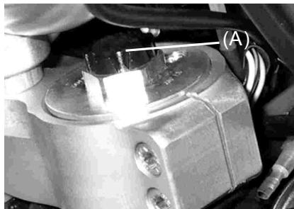
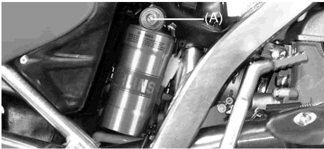
Shock Rebound dampening Adjustment Rear shock Absorber
o adjust shock rebound dampening, turn the rebound dampening adjuster on the rear shock absorber lower end until you feel a click.
The total number of adjustments is: 60 "CLICKS".
The standard setting is: 25 "CLICKS".
(Counterclockwise from fully closed).
(A). Rebound dampening adjuster
Shock compression dampening adjustment
To adjust schock compression dampening, turn the adjuster screw on the gas reservoir until you feel a (click).
The total number of adjustments is: 60 "CLICKS".
The standard setting is: 30 "CLICKS".
(Counterclockwise from fully closed).
(A). Compression dampening adjuster
Adjusting the spring
- Remove the seat, right and left side number plates.
- Loosen the air cleaner duct clamp screw.
- Remove the silencer.
- Remove the rear subframe with the air cleaner box.
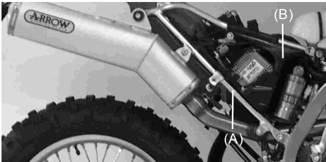
(A). Rear Subframe
(B). Air Cleaner Box
Suspension spring
The standard spring is a 4.0.
The standard spring preload length is 258~mm
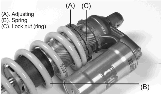
- Tighten the locknut (ring) securely.
- After adjustment, move the spring up and down to make sure that the spring is seated.
- Install the parts removed.
Rear Shock Absorber Spring Replacement
In addition to the standard spring, harder and softer springs are available. If the standard spring is improper for your purpose, select a proper one according to the rider's weight or course conditions.
. Using the harder spring:The spring rate is higher.
. Using the softer spring:The spring rate is lower.
NOTE
Look at page 62.
WARNING
Improper removal of the spring from the rear shock absorber body may cause the spring and associated parts to be ejected at high velocity. Always wear eye and face protection. Removal and installation of spring should be performed by an person or company.
WHEELS
Tires
- Tire pressure affects traction, handling, and tire life.
- Adjust the tire pressure to suit track conditions and rider preference, but do not stray too far from the recommended pressure.
NOTE
Tire pressure should be checked when the tires are cold before you ride.
Track condition
- When the track is wet, muddy, sandy or slippery, reduce the tire pressure.
- When the track is pebbly or hard, increase the tire pressure.
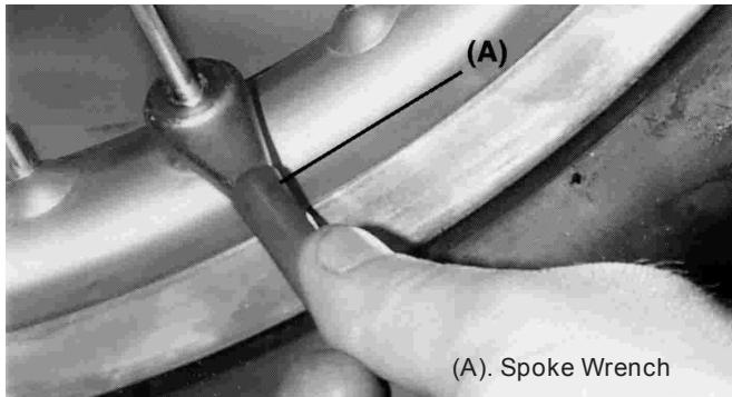
Spokes and Rim
The spokes on both wheels must all be tightened securely and evenly and not be allowed to loosen. Unevenly tightened or loose spokes will cause the rim to warp, hasten nipple and overall spoke fatigue, and may result in spoke breakage.
Tire bead lock (clamp)
There is a lock (clamp) on the front and rear wheels. The bead lock (clamp) prevents the tire and tube from slipping on the rim and damaging the valve stem. Valve stem damage may cause the tube to leak, necessitating tube replacement. In order that the tire and tube remain fixed in position on the rim, inspect the bead lock (clamp) before riding and tighten it if necessary. Tighten the valve stem nut finger tight only.
NOTE
The weld joint area of the rim may show excessive runout. Disregard this when measuring runout.
Cleaning
1- Preparation for washing
Before washing, precautions must be taken to keep water off the following places:
Rear opening of: The silencer cover with a plastic bag secured with rubber bands
Clutch and brake levers, hand grips, engine stop button: Cover with plastic bags.
Air cleaner intake: Close up the opening with tape or stuff in rags.
2-Where to be careful
Avoid spraying water with any great force near the following places:
-
Under the fuel tank : If water gets into the ignition coil or into the spark plug cap, the spark will jump through the water and be grounded out. When this happens, the motorcycle will not start and the affected parts must be wiped dry.
-
Disc brake master cylinders and calipers.
- Front and rear hubs.
- Steering pivots (Steering stem head pipe).
- Suspension linkage system pivots.
- Swing arm pivot.
3- After washing:
- Remove the plastic bags, and clean the air cleaner intake.
- Lubricate the points listed in the lubrication section.
- Start the engine and run for 5 minutes.
- Dry the brakes before operating the motorcycle.
WARNING
Never wax or lubricate the brake disc. Loss of braking and an accident could result. Clean the disc with an oil-less solvent such as trichloroethylene or acetone.
Bolt and Nut Tightening
Every day before riding, check without fail the tighteness of the bolts and nuts described here. Also, check to see whether or not each cotter pin is in place and in good condition.
1-Front/rear rim
2- Front fork
3- Handlebar mounting bolt
4- Clutch lever support bolt
5- Subframe support bolt
6- Air cleaner bolt
7- Seat support bolt
8- Spokes
9- Disc plate screws
10-Front axle clamp nut
11-Brake hose clamp nut
12-Brake hose mounting bolt
13-Radiator mounting nut
14-Engine mounting nuts
15-Shift pedal bolt
16-Chain guide bolts
17-Chain adjuster locknuts
18-Rear axle nut
19-Silencer mounting bolts
20-Subframe bolts
21-Rear shock absorber bolts
22-Exhaust mounting bolts and nuts
23-Fork clampbolts
24-Steering shaft nut
25-Rear brake mounting bolt
26-Connecting rod mounting bolt
27-Rear brake pedal bolt
28-Rocker arm mounting bolt
29-Swingarm shaft nut
Torque Table
Tighten all bolts and nuts to the proper torque using an accurate torque wrench. A bolt or nut if insufficiently tightened may become damaged or fall out, possibly resulting in damage to the motorcycle and injury to the rider.
| PART NAME | N-m / FT.LBS. | Kg-m / IN.LBS. | |
| ENGINE | Engine drain plug | 20 / 15 | 2.0 / 177 |
| Kick pedal bolt | 20 / 15 | 2.0 / 177 | |
| Kick pedal nut | 25 / 18 | 2.5 / 221 | |
| Shift pedal bolt | 10 / 7 | 1.0 / 88 | |
| Spark plug | 11 / 7.7 | 1.0 / 88 | |
| Water pump cover drain plug | 9 / 6.6 | 0.9 / 80 | |
| CHASSES | Caliper mounting bolts | 25 / 18 | 2.5 / 221 |
| Disc plate mounting screws | 10 / 7 | 1.1 / 96.8 | |
| Engine mounting bolts | 36 / 26.5 | 3.6 / 318 | |
| Front axle bolt | 51 / 38 | 5.1 / 451 | |
| Front brake lever support nut | 6 / 4 | 0.6 / 53 | |
| Fork flange nut | 29 / 21 | 3.0 / 256 | |
| Steering nut | 98 / 72 | 10.0 / 866 | |
| Rear axle nut | 98 / 72 | 10.0 / 866 | |
| Rear brake pedal nut | 9 / 6,6 | 0.9 / 80 | |
| Subframe support nut | 26 / 19 | 2.7 / 230 | |
| Rear shockabsorber nut | 39 / 28 | 4.0 / 345 | |
| Rear disc wheel drive nut | 29 / 21 | 3.0 / 256 | |
| Spokes | 1.5 / 1.1 | 0.15 / 13 | |
| Axle clamp nuts | 4 / 3 | 4.5 / 35 | |
| Swingarm pivot bolt | 81 / 60 | 8.3 / 716 | |
| Tornillo bieletas | 81 / 60 | 8.3 / 716 |
LUBRICATION
Lubricate the points shown here, with either motor oil or regular grease, in accordance with the Periodic Maintenance Chart or whenever the vehicle has been operated under wet or rainy conditions, and especially after using a high pressure spray washer. Before lubricating each part, clean off any rusty spots with rust remover and wipe off any grease, oil, dirt, or grime.
General lubrication
- Clutch lever (A).
- Front brake lever (B).
Rear brake pedal (C). - Rear brake rod joints (D).
-Shift pedal (E).
Use an aerosol cable lubricant with a pressure luber:
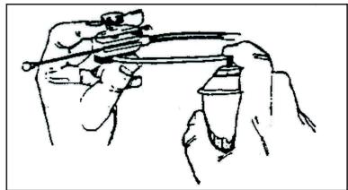
Apply grease to the following point throttle inner cable upper ends.
Chain lubrication
Lubricate the chain after drive over wet places or when the chain looks dry. It's better a high viscosity oil than a small viscosity oil because it will stay a long time in chain.
ENGINE OIL:
Ensuring a long engine life depends on using good oil and changing it periodically. Checking the oil level and making the changes periodically are two very important things to keep the engine in perfect shape.
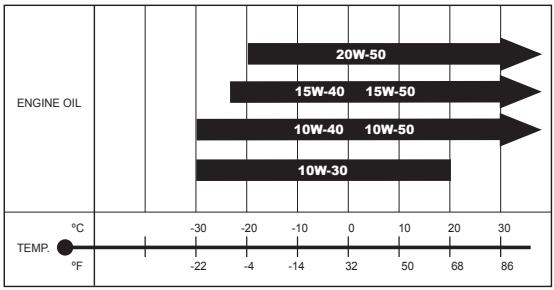
The recommended viscosity is SAE 10W-50, if a SAE 10W-50 oil is not possible, use one of the last table.
Checking the oil level and replacing periodicity are two important things for the engine.
Beginning you have to replace 5 hours ago of the start and then every 60 hours.
Checking the oil level:
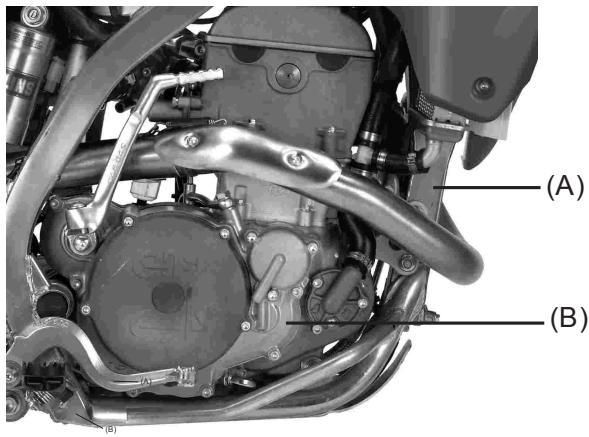
Fig. (A) When the engine has been running.
Fig. (B) When the engine has been stopped for a week.
The oil is pumped from the oil reservoir to the engine when the latter is running. The oil reservoir in this motorcycle is located in the top front part of the frame. The oil level, when the bike is not in use, decreases. The oil level drips down into the engine case. To check the oil level, follow these instructions :
- If the bike has been stopped for a week, we can be sure that all the oil is within the engine case.
NOTE:
When starting the engine, closely follow care and warnings from the "start the engine" section.
- Stop the engine and wait three minutes.
-
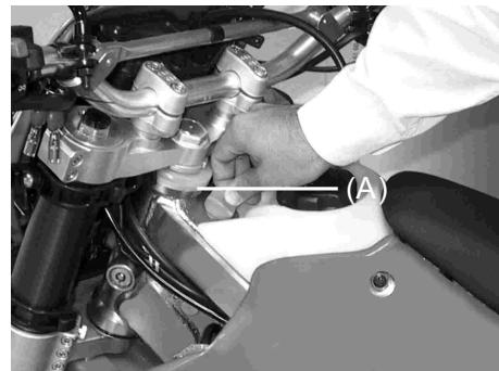
After removing the cap, remove the dipstick next. (A).
-
Wipe the dipstick clean with a rag.
-
Turn the cap of the dipstick (A). After removing the cap, remove the dipstick next.
-
Remove the dipstick and check the oil level. Oil level must be between line (L) (LOW) and (F) (FULL). If that is not the case, fill up the reservoir until the level reaches just the (F) line.
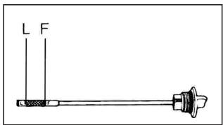
CAUTION
The level of the motor oil has to be between line «L» and line «F», engine damage may occur otherwise.
Check the oil level with the dipstick, with the bike in a completely upright position, every time you are going to use the bike.
NOTE:
Motor oil expands and descends when it is hot. Check and adjust the level when the motor oil is not hot.
Cange of oil and filter:
The oil should be changed when the engine is hot, since this helps the oil to go out through the drain located in the lowest part of the engine. Follow these steps to change the oil.
WARNING
The engine oil and the outpour tube can be very hot and cause burns.
Wait until the oil and the outpour tube are a little colder, by touching the oil drain with your hand.
WARNING
Using new or used oil may be hazardous. Permanent contact of oil with the skin has caused skin cancer in many lab animals. Avoid contact of motor oil with the skin as much as possible, to avoid possible skin irritation.
- Keep new or used oil away from the reach of children
- Clean jersey cuffs and pants
- Wash yourself with soap if oil has been in contact with your skin.
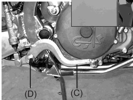
To check the oil level follow these instructions:
- Special spot for oil drain
recycle and dispose of used motor oil in an appropriate container.
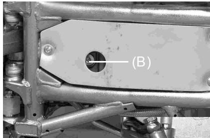
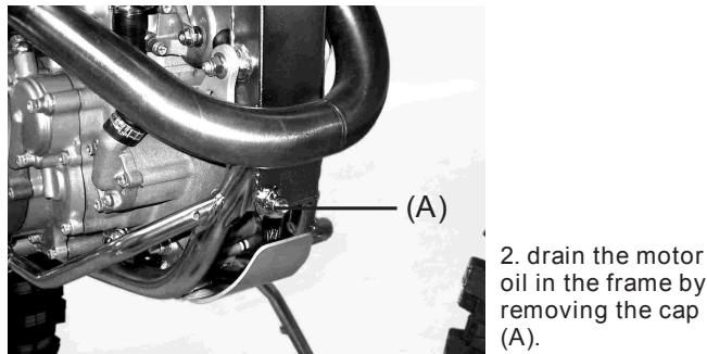
- Drain the oil from the engine by removing the cap (B), keeping the bike upright at all times.
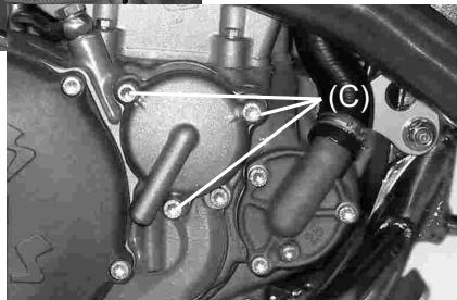
- Remove the three screws next to the filter cover (C).
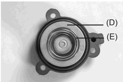
- Turn and remove the filter (D) and replace it by another new one.
WARNING
Using a filter with an incorrect design may cause engine malfunction. Use the oil filter with the genuine GAS GAS design or equivalent for your motorcycle.
WARNING
A mistake in the placement of the new element may cause engine malfunction. The motor oil will not flow if the new element is placed incorrectly.
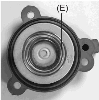
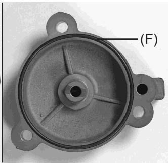
- Before replacing the oil filter, make sure that the spring (E) and the o-ring (F) are in the correct position.
NOTE
Put a new «o-ring» at the same time the filter is replaced.
- Replace the filter cover and put the screws that secure the cover, but without tightening them too hard.
- Replace the drain caps and screw them back on. Pour new oil through the dipstick hole. Approximately 1800 ml, or else the required amount.
WARNING
The engine can be damaged if the oil is not used properly or the specifications recommended by GAS GAS MOTOS are not followed.
Use the type of oil in the section of «recommended gasoline and oil specifications».
- Start the engine and let it idle for five minutes. Check that oil is not leaking anywhere.
- Check that the oil level is correct.
SUSPENSION TUNING
No area of machine adjustment is more critical than proper suspension tuning. An improperly tuned suspension will keep even the best rider from attaining the full benefit of his machine's ability. Match the suspension to the rider and the course conditions. Cuando afine la suspensión no debe olvidar:
-
If the machine is new, break-in the suspension with at least one hour of riding before making any setting evaluations or changes.
-
The three major factors which must be considered in suspension tuning are RIDER WEIGHT, RIDER HABILITY, and TRACK CONDITIONS. Additional influences include the RIDER'S STYLE and POSITIONING on the machine.
-
If you have a problem, test by changing your riding posture or position so that the cause of the problem can be deduced.
-
It is a wise practice to adjust suspension settings to suit the rider's strong points. If you are fast through the corners, adjust the suspension to allow fast cornering.
-
Make setting changes in small increments; a little bit goes a long way, and it is very easy to overadjust a setting.
-
The front and rear suspension should be balanced; when one is changed, the other might need to be changed similarly.
-
When evaluating suspension performance the rider must make every effort to ride consistently and recognize the effects of his input; such things as changes in rider position and increasing fatigue may lead to incorrect judgments about necessary setting adjustments.
-
When the proper settings have been determined for a particular track, they should be written down for reference when returning to that track.
Front Fork
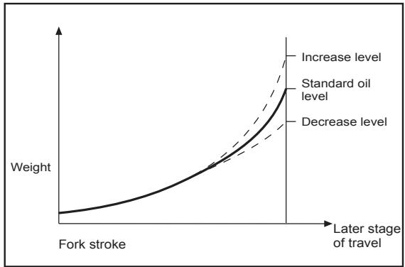
The fork oil level in the fork tube is adjustable. A change in the fork oil level will not affect the spring force much at the top of fork travel, but it will have a great effect at the bottom:
- When the oil level is raised:
The air spring effect becomes more progressive, and the front fork action feels "harder" in the later stage of travel, near the bottom.
- When the oil level is lowered:
The aire spring is less progressive, and the front fork does not become as "hard" in the later stage of travel.
- Changing the fork oil level works effectively at the end of fork travel. If fork bottoming is experienced, raise fork fork oil level in 10mm increments. This will change the secondary spring rate.
Oil level adjustment
Adjust the front fork oil level (see the Oil Level Adjustment of the Front Fork section in the Maintenance and adjustment chapter).
Troubleshooting Improper Settings
Listed below are some symptoms of improper suspension settings and the most likely means of correcting them.
The proper settings can be achieved by applying the information in this chapter in a scientific, methodical manner; this does not mean, however, that you must be a scientist or trained technician to succeed. Simply take time a think about the changes you believe necessary, check them against the symptoms and cures described here, make the changes in small increments, and take notes on the changes and their effects.
Symptoms of the Front Forks
Too hard
- The front forks are too stiff
Rebound or compression damping adjustment incorrect.
The springs are too strong.
. Too much oil.
. Too heavy oil.
- The front forks stiffens up the end of stroke
. The fork oil level is too high. - The front forks operate but ride is too hard
Oil too heavy.
Worn out fork oil.
Too soft
- The fron fork dive excessively during braking and deceleration
Fork oil level is low.
Springs are too soft.
Oil too light.
. Fork oil is worn out.
. Rebound or compression damping adjusting incorrect.
Symptoms of the rear shok:
Too hard
- The suspension is too stiff
. Compression damping is too high.
Spring is too hard.
Too soft
- On landing after a big jump, bottoming occurs (normally O.K.).
. Spring preload is too soft or compression damping is too soft.
Spring is too soft.
Shock oil is worn.
Determining the Proper Settings:
- Standard Settings
From the factory, the machine is set up for an intermediate-weight rider possessing intermediate riding ability. Hence, if the actual rider weight is considerably more or less than this, or if his riding experience and ability are much greater or lesser than the intermediate made to put the suspension "in the ballpark".
- Readjustment of the suspension
| Smooth | Softer spring |
| Rough | Harder spring |
Riding experience
Beginner Soffer: spring with more rebound damping.
Experienced: Harder spring.
Rider's weight
Heavy: Harder spring.
Light: Softer spring.
Type of course
- Many corners:
Lower the front end slightly (increase the fork tube height 5mm). This quickes steering and turning ability.
- Fast course with many jumps:
Raise the fornt end slightly (decrease the front tube height 5mm
- Deep whoops, or sandy ground:
Raise the front end slightly to gain stability.
After making such preliminary adjustments, begin the actual on-track testing and evaluation.
Remember:
1- Always make changes in small increments.
2-Make sure the rider is consistent in this evaluation of improper suspension performance.
3- A change in the front suspension might require a change in the rear, and vise versa.
Front and rear compatibility:
Use this procedure to determine if the suspension is balanced reasonably well: Hold the bike upright (retract the side stand). While standing next to the machine, lightly pull on the front brake, place one foot on the footpeg closest to you, and push down hard. If the bike maintains its level attitude as the suspension is compressed, the spring rates are well balanced. Sit astride the bike and take a riding posture. Next check to see that the bike is in a horizontal position. If one end drops noticeably more than the other, the front and rear are not compatible and must be readjusted to achieve a better balance.
This is one of the most effective adjustment procedures but suspension settings will vary depending on the conditions at the track and the rider's preferences.
Front end seaching during down hill or during acceleration out of corner:
Front fork is too soft.
- Increase the compression damping or rebound damping.
- Increase the oil level 10mm
- Use alternate harder sping, or increase spring preload.
Front end "knifes"or oversteers in turns: (front end tends to turn inward)
Front fork is too soft.
- Increase the compression damping or rebound damping.
- Increase the oil level 10mm
Front end pushes or "washes out" in turns:
- Decrease the compression damping or rebound damping.
- Release the air at the fork tubes.
- Decrease oil level 10 - 20mm
- Use softer spring.
Front fork doesn't respond to small bumps in sweeping turns:
-
Front Fork is too hard:
-
Decrease the compression damping or rebound damping.
- Decrease oil level 10mm
- Use softer duty spring.
Rear end "kicks" when braking over bumps:
The shock probably has too little rebound damping.
- Increase the rebound damping.
Rear tire won't "hook up" out of corners:
(A lack of traction coming out of turns)
-
The shock may be too stiff:
-
Decrease the rear shock spring preload.
- Decrease the compression damping.
- Use softer spring (In case of a lightweight rider).
Front and rear of the bike bottom off high speed jumps: (If harsh bottoming occurs once or twice per lap of the race)
. Front and rear suspension system are too soft.
- Delantera: Increase oil lever and/or use harder spring.
- Rear: Increase spring preload and/or increase compression damping or use harder spring.
NOTA:
After any adjustment, check front and rear compatibility.
Adjustment depending on bottoming condition:(rear shock absorber).
- Bottoms at low speed.
- Increase spring preload until maximum preload is achieved.
- Bottom after successive 3 or 4 successive jumps.
- Decrease rebound damping.
NOTE
The rear shock on this machine may mislead some riders.
a) The rear shock bottoms when the spring and damping are overcome by the total weight of the machine and rider (due to full stroke).
b) A bottoming sensation (even through the machine is not bottoming) may actually be the inability of rider and machine weight to overcome an overly stiff spring or excessive damping.
Observe the rear end off jumps; if it doesn't approach bottoming, try lowering the sping preload and damping.
Gearing
Preconditions:
| Course condition | Rear sprocket |
| Fast course Many courses or hills Sandy or soft groud | Small Large |
-
Si la parte recta de la "crono" es larga, el desarrollo可以选择 alargarse por lo tanto la velocidadurrenta.
-
If the straight portion of a course is longer, the secondary reduction ratio should be reduced so that the machine speed can be increased.
- When the course has many corners or uphills or is wet, the secondary reduction ratio should be increased so that gear shifting is possible with smooth acceleration.
- Actually, the speed must be changed depending on the ground condition on the day of race and therefore, be sure to run through the racing circuit prior to a race and set the machine suitable for the entire course.
- If the straight portion of a course on which the machine can be run at maximum speed is longer, the machine should be set so that the maximum machine speed can be developed toward the end of the straight course, but care should be taken not to over-rev the engine.
- It is difficult to set the machine to be best suited for all portions of the circuit. Therefore, determine which circuit portions will have the greatest effect on lap time. Set the machine for these portions. Confirm your settings by recording lap times after each change. In this way the machine will deliver best performance for the entire circuit.
Special Care According to Track Conditions.
- In dry, dusty conditions (such as volcanic ash or fine powdery dust) special care must be given to keep the air cleaner element clean.
-
When riding on wet heavy clay the mud adheres to the tires and other parts of the vehicle. The mud can add significantly to the weight of the vehicle and therefore reduce performance. Take care to remove built-up mud from the tires and chassis after each ride, before drying occurs.
-
The engine works hardest in muddy conditions and the radiator can become clogged with mud. Take care not to overheat the engine in these conditions. The engine also works very hard when ridden in deep sand.
- In muddy or sandy conditions adjust the chain looser than in other conditions as the chain and sprockets will pack with mud/sand and reduce chain slack.
- Check chain and sprocket wear frequently when riding in mud or sand since wear is increased in these conditions.
- In dusty conditions as the air cleaner collects dust, the engine runs richer. Therefore it may be advisable to run slightly leaner jetting (main jet) in very dusty conditions.
SPARE PARTS
carburation
front sprocket
rear sprocket
front suspension springs
rear suspension spring
PREPARATION FOR COMPETITION
(1). Check:
- Front axle shaft and nut, or axle clamp nut tightness
- Front fork clamp bolt tightness
- Handlebar clamp bolt tightness
- Throttle grip screw tightness
- Throttle grip operation
- Front and rear brake hose installation
- Front and rear brake fluid level
- Front and rear brake disc and caliper installation
- Front and rear brake function
- Fuel tank installation
- Shift pedal bolt tightness
- Engine mounting bolt tightness
- Engine sprocket installation
- Brake pedal bolt tight
- Transmission oil level
- Carburetor clamp screw tightness
- Carburetor top cap tightness
- Linkage tie rod mounting bolt tightness
- Linkage rocker arm mounting bolt tightness
- Rear shock absorber bolt tightness
- Swing arm pivot shaft nut tightness
- Rear axle shaft nut tightness
- Rear sprocket bolts or nuts tightness
- Rear brake pedal operation
- Seat installation
- Front and rear wheel stroke tightness
- Front and rear tire air pressure
- Drive chain slack
- Coolant level
(2). After first race maintenance
- Air cleaner element
- Drive chain slack
- Rear sprocket nuts
- Sprockets
- Front and rear tire air pressure
- Front and rear axle shaft nuts
- Pivot shaft nut
- Muffler, silencer bolts or nuts
- Front, rear fender mounting bolts or nuts
- Fuel tank, seat mounting bolts or nuts
- Front and rear brakes
- Steering play
- Fuel tank fill
- Coolant level check
(3) Maintenance notice for after riding on dusty course
If dirt or dust gets through into the engine, the crankshaft big end will wear excessively. After riding, inspect the crankshaft big end. If the crankshaft big end is worn past the service limit, replace the crankshaft big end with a new one.
(4) Maintenance notice for after riding in rain on muddy course
- Apply grease to swing arm pivot and rear suspension system
- Inspect the drive chain and rear sprocket wear
- Clean the air cleaner element
- Check the cylinder and crankshaft big end bearing
- Grease the throttle grip and cable
(5) Suggest spare parts
Look service manual
STORAGE
When the motorcycle is to be stored for any lenght of time, it should be prepared for storage as follows:
- Clean the entire vehicle thoroughly.
- Run the engine for about five minutes to warm the oil shut it off and drain the transmission oil.
- Put in fresh transmission oil.
- Empty the fuel from the fuel tank, and empty the carburetor float bowl. (If left in for a long time, the fuel will deteriorate).
- Remove the spark plug and put several drops of SAE 30 oil into the cylinder. Kick the engine over slowly a few times to coat the cylinder wall with oil, and install the plug.
- Lubricate the drive chain and all the cables.
- Spray oil on all unpainted metal surfaces to prevent rusting. Avoid getting oil on rubber parts or in the brakes.
- Set the motorcycle on a box or stand so that both wheels are raised off the ground. (If this cannot be done, put boards under the front and rear wheels to keep dampness away from the tire rubber).
- Tie a plastic bag over the exhaust pipe to prevent moisture from entering.
- Put a cover over the motorcycle to keep dust and dirt from collecting on it.
To put the motorcycle back into use after storage.
- Remove plastic bag from exhaust.
- Make sure the spark plug is tight.
- Fill the fuel tank with fuel.
- Check all the points listed in the Daily Pre-ride Inspection Section.
- Perform the General lubrication procedure.
The top button is the reset button. The bottom button is the mode button.
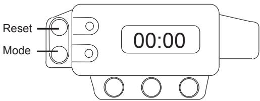
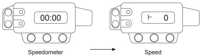
The initial display is the clock.(time) if you press mode (btm. button) the display goes:
- Speedometer.
- Speed (Km or miles).
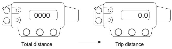
- Total distance in kmh or miles (this has a memory even if battery disconnected).
- Trip distance.
To change the time:
- Press mode until time display is shown.
- Press mode again keeping the button pressed the hour will display only add the hours by pressing the reset (top) button.
- Press mode again to adjust the minutes in the same way.
- Press mode again and the time is now set.
(when you have set the time the seconds automatically start from zero)
Trip distance:
- From time display press mode 3 times. (I-0) to zero the trip, keep the reset button pressed until it zeros.
To change to kilometers per hour or miles per hour:
- Disconnect the battery. (the total distance will be saved).
- Re-connect the battery whilst holding down either button and it will read either;
met -- for km/h
mil -- for mp/h
- The white plastic block connector on the speedo is for the display backlight.
- The red wire is positive.
- The black wire is negative.
- Warning; your speedo is set for the diameter of your front wheel
enduro 21"
supermoto 17"
If you get the display to read "a 00" then you are in the rolling radius changing mode. you can "trim" the speed to run fast or slow. It ranges from "a-25" to "a 25".
NOTE
Standard setting is "a 00", we recommend you keep it at that.
TROUBLESHOOTING
NOTA:
This is not an exhaustive list, giving every possible cause for each problem listed. It is meant simply as a rough guide to assist the troubleshooting for some of the more common difficulties.
| TROUBLE | CAUSE | REMEDY | |
| 1 | Starter engine doesn't crank | - Blown fuse in the starter relay. - Discharged battery. - Low outside temperatur | - Dismount the right paneling and the filter box cover and replace the fuse in the starter relay. - Recharge the battery and investigate the causes for discharging; contact a dealer. - Start engine with start pedal. |
| 2 | Engine doesn't crank | - Crankshaft seizure. - Cylinder-piston, connecting rod big end seizure. - Transmission set seizure. | - Go to specialized garage. - Go to specialized garage. - Go to specialized garage. |
| 3 | Engine cranks but doesn't start | -- Fuel supply interrupted. - The motorcycle has been out of operation for a longer period of time. Therefore old fuel has accumulated in the float chamber. - Scooty or wet spark plug. - Flooded engine. - The plug connection of the CDI unit, the pulse generator or the ignition coil has oxydized. - Fuel/ air mixture incorrect. | - Check fuel pump relay, extract air filter cover, check fuel pump isn't glogged. - Is recommended to drain the old fuel from the float chamber. - Clean and dry the spark plug or exchange it, respectively. - In order to "pump the engine free", pull de starter pedal 5 or 10 times or actuate the kickstarter 2 times in 5 seconds. Then, start the engine as described above. If the engine fails to start, unscrew the spark pulug and dry it. - Remove the seat and the fuel tank. Clean the plug connection and treat it with contact spray. - Clean tank cap air vent. Check by-pass throttle body. Check the air filter. |
| 4 | Engine start but stops few seconds ago. | - Incorrect air supply. - There isn't fuel. | - Close the starter. Clean fuel tank air vent. Check the injector mounting. Check the air filter. - Fill up fuel tank. |
| 5 | Engine gets to hot | - Insufficient cooling liquid. - Radiators very dirty. | - Close the starter. Clean fuel tank air vent. Check the injector mounting. Check the air filter. - Full up fuel tank. |
| 6 | Engine flooded | - Injection system maladjustment. - Incorrect valve gap. | - Adjust injection system. Go to specialized garage. - Adjust valve gap. Go to specialized garage. |
| 7 | Engine does not rev high, will not reach full power | - Fuel supply partially interrupted or carburettor dirty. - Dirty air filter. - Hose of engine ventilation is bent. - Valve gap to small. - Loss of compression. | - Clean and check fuel system as well as carburettor. - Clean and change the air filter. - Replace non-buckling ventilation hose. - Adjust valve gap. Go to specialized garage. - Check the good system work. |
| 8 | High oil consumption | - Cylinder-piston diameter tolerance higest. - Engine oil level higest. - Oil quality and viscosity incorrect. | - Adjust tolerance changing piston ring. - Check level oil engine. - Empty oil engine, and fill up with a recommended viscosity oil. |
| 9 | Abnormal engine noise | - Starter problem. - Carbon buit up in combustion chamber. - Overheating. | - Go to specialized garage. - Adjust valve gap. Go to specialized garage. - Look number 5. |
| 10 | Spark knock | - Carbon in combustion chamber. - Injection system maladjustment. - Incorrect or poor gasoline. - Incorrect spark plug. - Connecting rod exhaust system damage. | - Clean combustion chamber. - Go to specialized garage. - Empty, and fill up with good gasoline. - Cambiar bujía por otranea o adecuada. - Check if the exhaust system is damaged. Connecting rods have to be perfect, if they aren't, change them. |
| 11 | Exhaust pipe get out white smoke. | - Cylinder head gasket leaking. | - Change cylinder head gasket leaking. Go to specialized garage. |
| 12 | Exhaust pipe get out brown smoke. | - Air filter is bloked. | - Clean or change the air filter. Go to specialized garage. |
| 13 | Clutch not disengaging properly | - No clutch lever play maladjusted. - Friction plate worn or warped. - Steel plate worn or warped. - Gear lever damaged. - Clutch spring broken or weak. - Clutch release mechanism trouble. - Clutch hub or housing unevenly worn. | - Go to specialized garage. - Change friction plate. - Go to specialized garage. - Change gear lever. - Check or change clutch spring. - Check clutch release mechanism. - Change clutch hub. |
| 14 | Jumps out of gear | - Shift fork worn, gear worn. - Gear dogs and/or dog holes worn. - Shift drum groove worn. - Gear positioning. - Lever spring weak or broken. | - Change it and go to specialized garage. - Change it and go to specialized garage. - Change it and go to specialized garage. - Change it and go to specialized garage. - Change it and go to specialized garage. |
| 15 | Clutch slipping | - No clutch lever play, maladjusted. - Friction plate worn or warped. - Steel plate worn or warped. - Clutch spring broken or weak. - Clutch disc unevenly worn. | - Go to specialized garage. - Change friction plate and go to specialized garage. - Change steel plate. - Check or change clutch spring. - Change clutch disc. Go to specialized garage. |
| 16 | Stability Unsatisfactory | - Control cable routing incorrect. - Wiring routing incorrect. - Steering stem locknut too tight. - Steering stem bent. | - Move control cable or unscrew. - Unscrew wiring routing. - Change steering stem locknut. - Change and go to specialized garage. |
| 17 | Shock absorption too hard | - Front fork oil excessive. | - Empty and review level oil. |
| 17 | Shock absorption too hard | - Front fork oil viscosity too hight. - Front fork leg bent. - Tire air pressure too high. - Rear shock absorber maladjusted. | - Empty oil from fork and go to specialized garage. - Change it. Go to a specialized garage. - Check tire air pressure. - Check rear shock absorber. |
| 18 | Shock absorption too soft | - Front fork oil insufficient and/ or leaking. - Front fork oil viscosity too low. - Front fork leg bent. - Tire air pressure too small. - Rear shock absorber maladjusted. | - Fill up until correct level. - Empty oil from fork and fill up with suitable viscosity oil. - Change front fork. Go to specialized garage. - Check tire air pressure. - Check rear shock absorber. |
| 19 | Abnormal train noise | - Drive chain adjusted improperly. - Chain worn. - Rear and/or engine sprocket worn. - Chain lubrication insufficient. - Rear wheel misaligned. - Oil front fork insufficient or too thin. - Spring weak or broken. - Disc brake worn. - Pad installed incorrectly or surface glazed. - Cylinder damaged. - Bracket, nut, bolt, etc. not properly mounted or tightened. | - Adjust chain. - Change chain and rear engine sprocket. - Change it. - Lubricate with appropriate chain oil. - Align rear wheel. - Add oil until correct level. - Change spring. - Change disc brake. - Replace pad or change. - Change cylinder damaged. - Go to specialized garage. |
| 20 | Handlebar shakes or excessivery vibrates | - Tire, swing arm sleeve or needle bearin damaged. - Rim warped. - Wheel misaligned. - Front/ rear axle runout excessive. | - Change it for new pieces. - Centre rim. - Check wheel rim pressure. Adjust if it is necessary. - Check rear/ front axle steering. Adjust if it's necessary. |
| 21 | Motorcycle pull to one side | - Frame bent. - Steering maladjusted. - Steering stem bent. - Front fork bent. - Wheel misalignment. | - Go to specialized garage. - Adjust steering. Go to specialized garage. - Change steering stem and go to specialized garage. - Change front fork. - Align wheel. |
| 22 | Brakes don't hold | - Pad or disc worn. - Brake fluid leak. - Brake fluid deteriorated. - Piston pump damaged. - Brake maladjustment. | - Change disc. - Check and replace. - Empty brake fluid and replace with new recommended one. - Replace pump piston. - Adjust brake. |
| 23 | Las lámparas se funden | - El regulator de la tensión está defectuosos. | - Quitar el asiento y el depósito de gasolina y controlar las conexiones, vericar, el regulator de tensión y los fusibles de la caja de fusibles. |
| 24 | Elsystema de iluminación no funciona | - El fusible del relé de iluminación estáFundido. | - Quitar el asiento, la tapa de la caja de fusibles y cambiar el fusible. |
WARRANTY REGULATIONS
Manufacturer's warranty
The Company GAS GAS Motos S.A. hereby warrants to the final purchaser of a vehicle manufactured by GG that both materials and workmanship are free from defects according to the corresponding state of the art. Accordingly, GG hereby warrants to the final purchaser (hereinafter referred to as the «purchaser»), subject to the conditions stated below, to remove any defects in material or production detected in a new motorcycle free of charge within the agreed period of warranty without any limitation whatsoever in terms of the number of kilometres travelled or the number of operating hours.
Period of warranty
The period of warranty shall commence on the day of delivery of the vehicle by a licensed GG dealer to the purchaser, or in the case of demonstration models, on the date on which the vehicle is put into operation for the first time.
The length of the warranty period depends on the type of vehicle and is stated in the document of delivery.
Any defects detected in the product shall be brought to the attention of a licensed GG dealer within the warranty period. If the last day of the warranty period is a Sunday or public holiday, the warranty period shall be extended in such a way that the last day of the warranty period is the next working day following the respective Sunday or public holiday. Warranty claims shall be excluded for any defects not brought to the attention of a licensed GG dealer by the end of the warranty period.
Obligation of the purchaser
GG shall be entitled to refuse to accept warranty claims if and to the extent that:
a) The purchaser has failed to subject the vehicle to any of the inspections and/or maintenance work prescribed in the operating manual or has exceeded the date stated for such inspections or maintenance work, also excluding from the warranty defects that appeared before the prescribed date of such inspection or maintenance work performed not at all or performed only after the prescribed date.
b) Inspection, maintenance work and repair work on the vehicle has been performed by a party neither recognized nor licensed by GG; c) Any maintenance or repair work has been performed on the vehicle in violation of the technical requirements, specifications and instructions indicated by the manufacturer.
d) Spare parts not released for use by GG have been used to perform maintenance or repair work on the vehicle, or if and to the extent that the vehicle has been operated using other fuels, lubricants or operating fluids (including but not limited to cleaning agents) than those expressly stated in the specifications in the operating manual; e) The vehicle has been altered or modified in any way or equipped with other components than those expressly released by GG as admissible vehicle components.
f) The vehicle has been stored or transported in a way that does not meet the corresponding technical requirements.
g) The vehicle has been used for competitions, races or attempts at any record whatsoever.
Exclusion from warranty
The following items shall be excluded from warranty:
a) wear and tear parts including, without limitation, sparks plugs, batteries, fuel filters, oil filter elements, driving chains, engine sprockets, rear sprockets, air filters, brake discs, brake pads, clutch discs, lamps, fuses, carbon brushes, footrest rubbers, tires, tubes, cables and other rubber components.
b) Lubricants (e.g. oil, grease, etc.) and operating fluids (e.g. battery fluid, cooling liquid, etc.).
c) Inspection, adjusting and other periodical maintenance work as well as all kinds of cleaning work.
d) Damage to paint work and corrosion there of due to external influences such as stones, salt, industrial exhaust gases and other environmental impacts or inadequate cleaning with inadequate products.
e) Any consequential harms caused by defects as well as incidental expenses directly or indirectly related to defects (e.g. telecommunication charges, cost of board and lodging, cost of rental cars, public transport charges, cost of salvage and towing, overnight expenses, etc.) as well as other financial disadvantages (e.g. caused by loss of use of a motor vehicle, loss of earnings, loss of time, etc.). f) Any aesthetic or acoustic phenomena that does not significantly affect the serviceable condition of the motorcycle (e.g. hidden or minor blemishes, normal operating noise or vibrations). g) Phenomena due to the aging of the vehicle (e.g. fading of painted or metal-coated surfaces).
Miscellaneous
1.- GG shall be entitled to decide in its sole discretion whether to repair or to replace defective parts. The ownership of parts replaced, if any, shall pass to GG, free of any consideration whatsoever. The licensed GG dealer entrusted with the removal of defects shall not be authorized to issue binding declarations on behalf of. 2.- In cases of doubt regarding the existence of a defect or if a visual inspection or material testing is required, GG shall be entitled to demand submission of the parts for which warranty claims are put forward or to order an examination of the defect by a GG expert. Any additional warranty obligations for parts replaced free of charge or for any service performed free of charge under the present warranty shall be excluded. The warranty components replaced within the warranty period shall end at the date of expiry of the warranty period agreed for the respective product.
3.- If it turns out that any defect cannot be removed, the warranty shall be entitled to demand termination of the contract (payment of a compensation) or partial reimbursement for the purchasing price (discount) instead of repair of the motorcycle.
The warranty shall in no case be entitled to receive a new motorcycle as a substitute for the defective product.
-
- The warranty claims of the purchaser under the contract of purchase and sale concluded with the respective licensed dealer shall not be affected by the present warranty. Neither shall the present warranty affect any additional contractual rights of the purchaser under de General Business Conditions of the licensed dealer. However, such additional rights can only be claimed against the licensed dealer.
-
- If the purchaser resells the product within the warranty period, the terms and conditions of the present warranty shall continue to exist in their present scope, the right to put forward claims under the present warranty according to the terms and conditions hereof will be passed on to the new owner of the motorcycle.
December 2002