
AI540720 - Range hood GAGGENAU - Free user manual and instructions
Find the device manual for free AI540720 GAGGENAU in PDF.
| Product type | Ceiling-mounted island extractor hood |
| Brand | GAGGENAU |
| Model | AI 540-720 / AI 541-720 |
| Dimensions (W x D) | 47 3/16" x 27 9/16" (approx. 1200 x 700 mm) |
| Weight | 35 kg (without support frame or duct) |
| Electrical supply | See rating plate; connection via plug or circuit breaker |
| Extraction power | 3 speeds + 1 intensive speed (Int) |
| Lighting | Halogen 12 V / 20 W, integrated dimmer |
| Filters | Stainless steel grease filters (dishwasher-safe); activated charcoal filter (optional, ref. KF 001-010) |
| Special functions | Delayed shut-off (10 min), intermittent ventilation (5 min/h), adjustable intensive timer (3/5/10 min) |
| Saturation indicator | Flashing "F" display after 30 h of use |
| Noise level | Low noise level (values not specified) |
| Exhaust modes | External exhaust or recirculation (with charcoal filter) |
| Duct diameter | 6" / 150 mm |
| Installation height | 30" to 36" (76 cm to 91 cm) above the cooking surface |
| Material | Stainless steel, glass |
| Cleaning | Grease filters: dishwasher; exterior: soft cloth and mild detergent; glass panels: glass cleaner or dishwasher |
| Safety | Automatic shut-off of intensive speed after 5 min; short-circuit protection; installation instructions must be followed |
| Spare parts | Halogen lamps 12 V/20 W (G4), grease filters, charcoal filters, ventilation ducts |
| Repairability | Repairs exclusively by an authorized technician; use original parts |
Frequently Asked Questions - AI540720 GAGGENAU
User questions about AI540720 GAGGENAU
0 question about this device. Answer the ones you know or ask your own.
Ask a new question about this device
Download the instructions for your Range hood in PDF format for free! Find your manual AI540720 - GAGGENAU and take your electronic device back in hand. On this page are published all the documents necessary for the use of your device. AI540720 by GAGGENAU.
USER MANUAL AI540720 GAGGENAU
Operating and assembly instructions
AI 540-720 AI 541-720
Freely Suspended Insular Hood
Preface
Safety notes
- Important notes Page 4-5
1.1 For your safety
1.2 Operating for the first time
1.3 About use Page 5 - Features Page 6
- Operation Page 7-9
- Cleaning and care Page 10-11
- Maintenance Page 12
- Assembly instructions Page 13-18
6.1 Technical data Page 13
6.2 Installation Page 14-18
With your new extractor hood, working in the kitchen will be even more fun.
The appliance offers you a number of advantages:
- a good extraction capacity with low noise values,
- a large number of control functions,
- optimum illumination of the cooking surface by a dimmable halogen light.
To ensure that you will be able to use this appliance in all its diversity, read through the operating and assembly instructions conscientiously before operating it for the first time. The instructions contain important notes on use, installation and maintenance of the appliance.
On the following page you will find important notes on safety and operation. These will serve to ensure your personal safety and the lasting value of your appliance.
You will find notes on page 5 that you ought to observe before operating the appliance for the first time.
The chapters entitled "Structure and operating principle" and "Operation" will tell you all the things your extractor hood is capable of doing and how the appliance is operated.
Tips and hints in the chapter entitled "Cleaning and care" will make sure that your appliance will stay operable and beautiful for a long time.
And now we wish you lots of fun with your new extractor hood.
Read And Save These Instructions.
WARNING - TO REDUCE THE RISK OF FIRE, ELECTRIC SHOCK, OR INJURY TO PERSONS, OBSERVE THE FOLLOWING:
a.) Use this unit only in the manner intended by the manufacturer. If you have questions, contact the manufacturer.
b.) Before servicing or cleaning unit, switch power off at service panel and lock the service disconnecting means to prevent power from being switched on accidentally. When the service disconnecting means cannot be locked, securely fasten a prominent warning device, such as a tag, to the service panel.
CAUTION:
FOR GENERAL VENTILATION USE ONLY. DO NOT USE TO EXHAUST HAZARDOUS OR EXPLOSIVE MATERIALS AND VAPORS.
WARNING - TO REDUCE THE RISK OF A RANGE TOP GREASE FIRE.
a.) Never leave surface units unattended at high settings. Boilovers cause smoking and greasy spillovers that may ignite. Heat oils slowly on low or medium settings.
b.) Always turn hood ON when cooking at high heat or when cooking flaming foods.
c.) Clean ventilating fans frequently. Grease should not be allowed to accumulate on fan or filter.
d.) Use proper pan size. Always use cookware appropriate for the size of the surface element.
WARNING - TO REDUCE THE RISK OF INJURY TO PERSONS IN THE EVENT OF A RANGE TOP GREASE FIRE, OBSERVE THE FOLLOWING:
a.) SMOTHER FLAMES with a close-fitting lid, cookie sheet, or metal tray, then turn off the burner. BE CAREFUL TO PREVENT BURNS. If the flames do not go out immediately, EVACUATE AND CALL THE FIRE DEPARTMENT.
b.) NEVER PICK UP A FLAMING PAN - You may be burned.
c.) DO NOT USE WATER, including wet dishcloth or towels - a violent steam explosion will result.
d.) Use an extinguisher ONLY if:
- You know you have Class ABC extinguisher, and you already know how to operate it.
- The fire is small and contained in the area where it started.
- The fire department is being called.
- You can fight the fire with your back to an exit.
1. Important notes
1.1 For your safety
- Damaged appliances must not be operated.
- The appliance must only be connected by an authorised specialist, paying attention to the relevant regulations of the power supply companies and the regional construction regulations.
Also observe the assembly instructions!
- Connecting cables must not come into contact with hot cooking surfaces.
- Do not operate the extractor hood without inserted lamps.
- Never operate the appliance without a grease filter.
- Hazardous or explosive substances and vapours must not be extracted!
- The user is responsible for expert use and the perfect condition of the appliance.
- Only operate the appliance under supervision.
- Caution! Over-greased filters are a fire risk! Only ever deep-fry under the extractor under constant supervision. Be sure to clean the grease filter on a regular basis and change the activated charcoal filter.
- Fire risk! Do not flambé meals under the extractor hood!
- Operation of the extractor hood above a hearth for solid fuels, which poses a fire risk (e.g. sparks) is only permitted, if the hearth possesses a closed and fixed lid. The current local regulations must be obeyed. This does not apply to gas hobs and gas cookers.
- Hobs may only be used under the extractor hood when pots and pans are placed on them!
- When using more than 3 gas-operated rings at the same time, please operate the extractor hood at level 2 or higher. This prevents a buildup of heat in the appliance.
-
For safety reasons, do not place any heavy objects on the top of the appliance.
-
Do not clean the appliance with a steam cleaning apparatus or with water pressure because this poses a risk of short-circuits.
- Isolate the appliance from the mains during every maintenance operation. To do this, remove the mains plug or actuate the corresponding fuse.
If the mains plug is not accessible, the appliance must be switched off at fuse point.
- Repairs must be carried out by authorised specialists, thus ensuring electrical safety.
- No warranty claims can be lodged in the event of damage caused by failure to observe these instructions.
- Adequate incoming air must be ensured if a wood, coal, gas or oil heater or an open hearth is operated in the same room as the one in which the hood is installed.
- Safe operation is possible whenever the partial vacuum in the place where the firing equipment is installed does not exceed 4 Pa (0.04 mbar).
This can be achieved whenever the air needed for combustion is able to enter through openings that cannot be sealed, for example in doors, windows, incoming/exhaust air wall boxes or other technical means.
- If the appliance is to be operated only with the window open (to ensure adequate incoming air), you can use the window switch.
A switch (normally open) is fitted on the window. On the appliance, this switch is connected to the window switch terminal on the main electronics. The appliance can now only be operated when the window is open.
Important: the window switch must only be connected by an authorised specialist.
Note: the light function works without restriction.
- After a power failure, the extactor will not go on again automatically. You can recommence operation by turning a knob or by pressing any key.
Technical modifications reserved.
1.2 Operating for the first time
Before operating the appliance for the first time, please pay attention to the following notes:
- The appliance must be installed and connected by a specialist before it is operated for the first time.
- Conscientiously read through the operating and assembly instructions before operating the appliance for the first time.
- Remove the packaging from the appliance and dispose of it properly! Pay attention to the fact that there are accessories in the packaging! Keep packaging elements (e.g. plastic foil, styrofoam parts) out of the reach of children!
- Thoroughly clean the appliance before using it for the first time (see chapter "Cleaning and care").
- Before operating the appliance for the first time, check that the mains connection is in proper working order.
1.3 About use
- The appliance is intended solely for use in the household and must not be put to any other uses.
- In the event of malfunctions, first of all check the household fuses. If the problem has nothing to do with the power supply, please contact your specialist dealer or your local Gaggenau after-sales service.
- When children become old enough to operate the appliance, it is the legal responsibility of the parents or legal guardians to ensure that they are instructed in safe practices by qualified persons.
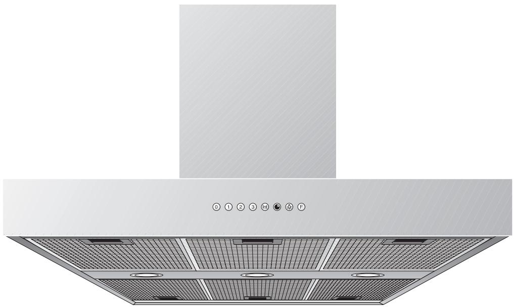
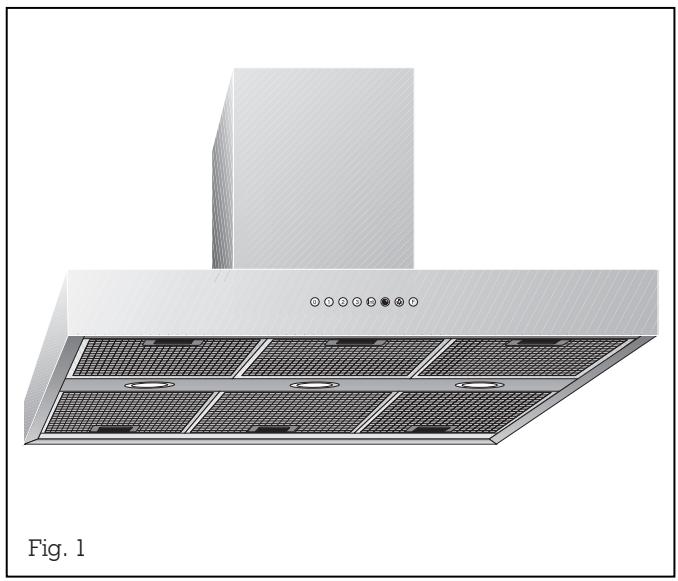
2. Features
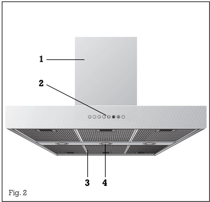
1 Ventilation duct
2 Control panel
3 Grease filters
4 Lighting
Installation accessories for exhaust air mode
Stainless steel-design ventilation duct:
LK 010-016 for ceiling heights of 7^4^ - 7^11^
LK 010-026 for ceiling heights of 7^11^ - 9
LK 010-036 for ceiling heights of 9^ - 9^9^
Aluminium-design ventilation duct:
LK 011-016 for ceiling heights of 7^4^ - 7^11^
LK 011-026 for ceiling heights of 7^11^ - 9
LK 011-036 for ceiling heights of 9^ - 9^9^
Installation accessories for circulating air mode
Stainless steel-design ventilation duct:
LK 010-126 for ceiling heights of 7^11^ - 9^
LK 010-136 for ceiling heights of 9^ - 9^9^
Aluminium-design ventilation duct:
LK 011-126 for ceiling heights of 7^11^ - 9'
LK 011-136 for ceiling heights of 9^ - 9^9^
3. Operation
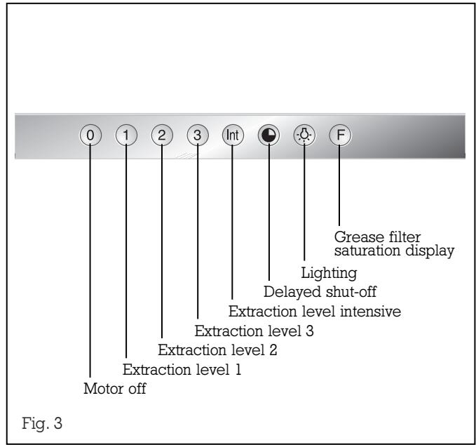
After they have been pressed, all functions selection keys except 0 ("Motor off") are backlit in green.
Light
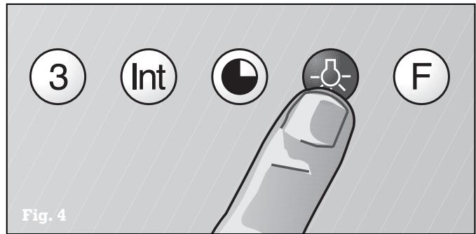
The lighting can be switched on or off, regardless of whether the extractor hood is in operation, by pressing the key (see Fig. 4).
When you briefly press the key, the lighting is increased up to the maximum level.
You can dim the lighting to the required level by keeping the key pressed.
Fan levels
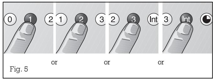
Three fan speeds and one intensive speed are available (see Fig. 5). You set the fan level required for each respective cooking situation by pressing the function selector keys 1, 2, 3 or Int.
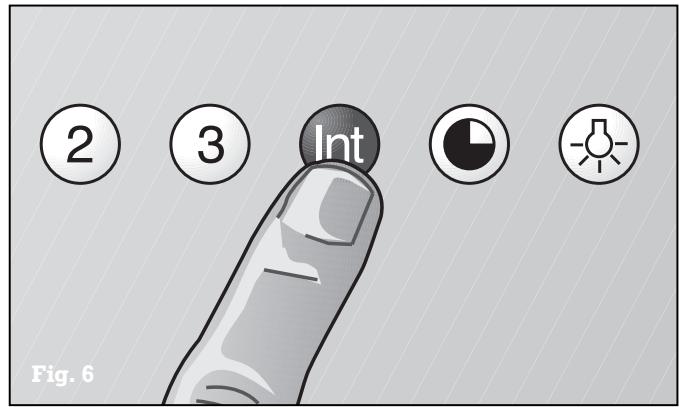
The Int key for the intensive level should be pressed when browning and frying in an open pan (see Fig. 6).
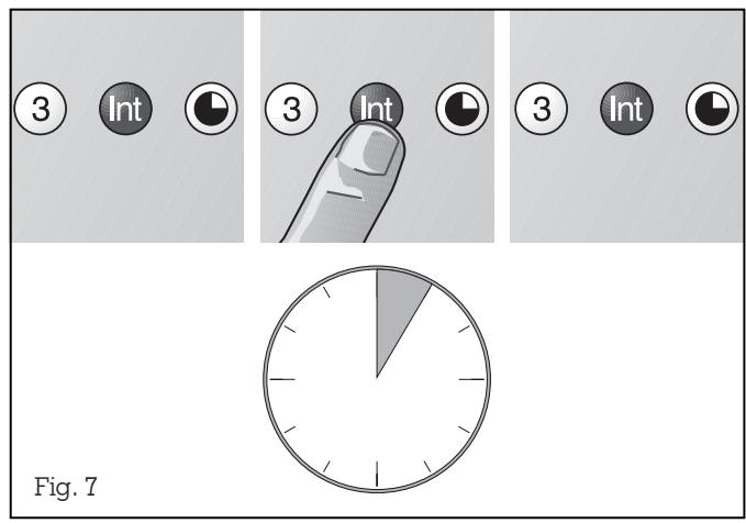
If you have switched on the hood by selecting the intensive level, it will be switched off again automatically after 5 minutes.
If you press the Int key while the hood is running at fan level 1, 2 or 3, the electronic control will switch back automatically to the previously selected fan level after 5 minutes (see Fig. 7).
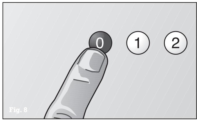
If you would like to end the intensive level before the five minutes have elapsed, press the 0 key ("Motor off") or select a different level (see Fig. 8). It is possible to switch off the extraction function at any time by pressing the 0 key (motor "off").
Special functions:
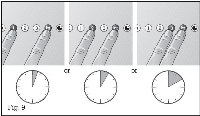
Intensive time:
You can set the intensive level running time to 3, 5 or 10 minutes by simultaneously pressing the Int key and the 1, 2 or 3 key and you can store this setting (see Fig. 9). When delivered, the appliance is set to five minutes, i.e. the combination of the Int key and the key 2.
Delayed shut-off:
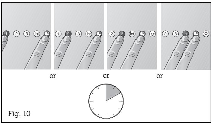
Delayed shut-off is possible at any level. First press the required key 1, 2, 3 or Int and then press the key (see Fig. 10).
The delayed shut-off time for all levels is ten minu-tes. After these ten minutes, the ventilation switches off, but the lighting stays on.
Interval ventilation:
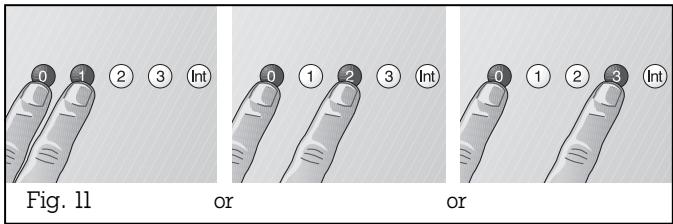
Interval ventilation is a special feature of this appliance which periodically activates the fan for five minutes every hour. You can activate this function by simultaneously pressing the 0 key and, depending on the required extraction capacity, the 1, 2 or 3 key (see Fig. 11).
This mode of operation is indicated by alternating illumination of the key together with the corresponding fan level indicator.
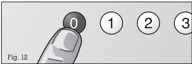
You can switch off interval ventilation by pressing the 0 key (see Fig. 12).
4. Cleaning and care
Cleaning the grease filters
The grease filter saturation display F flashes after an operating time of 30 hours to you indicate to you that you should clean the grease filter (see Fig. 3). The grease filters can of course be cleaned at any time, even if the grease filter saturation display has not started to flash.
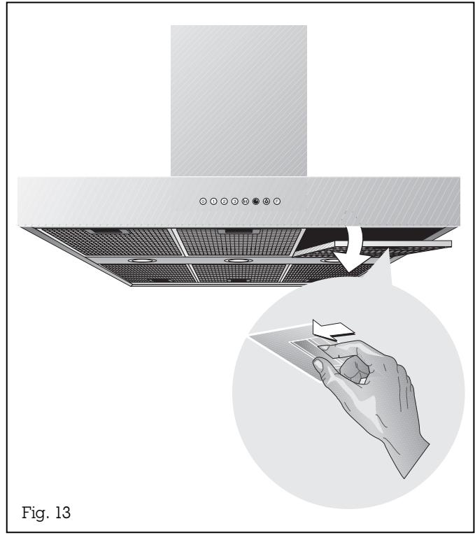
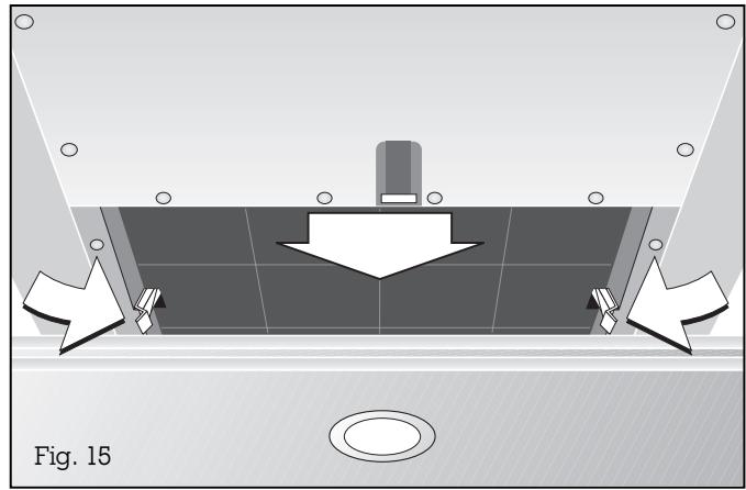
The stainless steel grease filters can be removed easily for cleaning (see Fig. 13):
Disconnect the power supply (switch off the fuse).
Grip the grease filter handle and push the slide towards the rear. Then pull the grease filter downwards out of the holder; repeat the operation for the other grease filters.
You can clean the stainless steel grease filters in a dishwasher at a maximum temperature of 130^ / 55^ , where it should be supported vertically to allow food or rinsing residues to drain off.
If possible, the inner parts of the housing should be wiped out in hot rinsing water when replacing the filters.
Caution:
when cleaning the inside of the housing, beware of protruding parts.
After having cleaned them, re-insert the grease filters in the extractor hood in reverse order.
Important:
the handles of both grease filters must be visible after assembly.
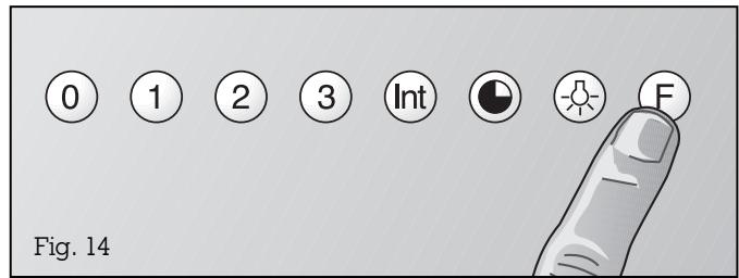
Press the F key to set the elapsed hours counter to zero. Flashing of the indicating lamp goes off.
Circulating air mode
The activated charcoal filter eliminates kitchen smells in the circulating air mode. In normal use (1 to 2 hours daily), the activated charcoal filter must be replaced approximately once a year.
If no activated charcoal filter is installed, kitchen smells will not be eliminated.
Replacing the activated charcoal filter
remove the stainless steel grease filters. Push in the clips on the side of the activated charcoal filter and remove the activated charcoal filter downwardly. Push the clips to the side and remove the activated charcoal filter towards the front.
Insert the activated charcoal filter at an angle. Then push the filter upwards, until the clips on the side lock into place. Re-insert the stainless steel grease filters.
Activated charcoal filters (KF 001-010) are available through your specialist dealer. Only use original filters.
Activated charcoal filters do not contain any dangerous substances. They can be disposed of through the household refuse collection.
Cleaning the extractor hood
Clean the exterior of your extractor hood with a soft cloth and mild detergent solution. Do not use any strong, caustic or abrasive cleaning agents. Do not use any abrasive sponges or brushes either.
Clean the stainless-steel extractor hood with stainless steel cleaner.
Cleaning the glass plates
Apply commercially available window cleaning agent with a soft, moist cloth. To facilitate cleaning, you can detach the glass plates as follows:
Detach the grease filters. In the extractor hood, you will find three openings on the upper side through which you can lift the glass plates singly with a blunt object (e.g. handle of a wooden spoon) to detach them with greater ease.
If they are extremely soiled, the glass plates can be cleaned in a dishwasher at a maximum temperature of 130^ / 55^ .
Note: when putting the glass plates back in place, make sure that you do not scratch the chimney. Replace the glass plates with the printed side facing down. Position the glass plates at the chimney side first.
Cleaning the aluminium panel
Clean the control panel with a sponge and mild detergent solution only. Dry with a soft, dry cloth. Do not use any strong or caustic cleaning agents or brushes and abrasive cleaner to clean it. Do not use strongly alkaline cleaning agents (such as oven spray) because these are aggressive to the aluminium surface. Do not use any abrasive sponges either.
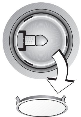
Fig. 16
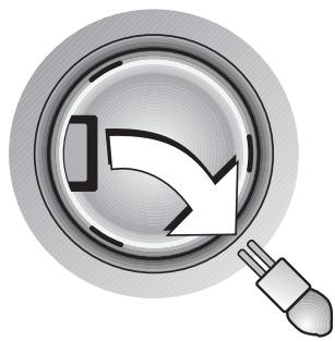
Fig. 17
The appliance must be disconnected from the power supply during all repair work.
If the appliance does not function correctly, check the fuses first.
If the power supply is functioning correctly, but your appliance still does not work, please contact your
Gaggenau dealer who will provide you with the address and telephone number of your nearest manufacturer's authorized service agent or contact
Gaggenau USA on (800) 828-9165. Specify the appliance type (see rating plate).
Repairs may only be carried out by authorised technicians, in order to guarantee the safety of the appliance.
Unauthorized tampering with the appliance will invalidate any warranty claims.
Only use original spare parts.
Lamp replacement
Caution: disconnect the power supply before replacing lamps (switch off the fuse)!
Caution: lamps may still be hot shortly after use! Risk of burns.
- Detach the ring from the lamp cover. Note: make sure that the glass will not fall out (Fig. 16).
- Pull out the lamp (Fig. 17).
Defective lamps must only be replaced by lamps of the same type! (12 V/20 W/G4 lampholder)
Inserting the lamp
- Insert the lamp in the lampholder.
Note: do not touch the halogen lamps with your hands. Use a cloth and touch the lamp only on its edges. - Engage the lamp cover.
- Connect the appliance to the mains again.
6. Assembly instructions
WARNING - TO REDUCE THE RISK OF FIRE, ELECTRIC SHOCK, OR INJURY TO PERSONS, OBSERVE THE FOLLOWING:
a.) Installation work and electrical wiring must be done by qualified person(s) in accordance with all applicable codes and standards, including fire-rated construction.
b.) Sufficient air is needed for proper combustion end exhausting of gases through the flue (chimney) of fuel burning equipment to prevent back drafting. Follow the heating equipment manufacturer's guideline and safety standards such as those published by the National Fire Protection Association (NFPA), and the American Society for Heating, Refrigeration and Air Conditioning (ASHRAE), and the local code authorities.
c.) When cutting or drilling into wall or ceiling, do not damage electrical wiring and other hidden utilities.
d.) Ducted fans must always be vented to the outdoors.
e.) If this unit is to be installed over a tub or shower, it must be marked as appropriate for the application and be connected to a GFCI (Ground Fault Circuit Interrueter) - protected branch circuit.
f.) NEVER place a switch where it can be reached from a tub or shower.
WARNING:
To reduce the risk of fire, use only metal ductwork.
6.1 Technical data
Weight without support frame and LK: 35 kg
Weight with support frame and LK: max. 60 kg
Dimensions : 47^3 / 16'' x 27^9 / 16''
Electrical connection
Pay attention to the rating plate data.
The appliance must only be connected by an authorised specialist. The specialist is responsible for perfect functioning of the appliance at its installation location. He must explain the operating principle of the appliance to the user with reference to the operating instructions. He must explain to the user how the appliance can be isolated from the mains whenever required.
Connection possibilities
The plug of the connecting cable is inserted into the socket on the ceiling. If this is not possible, the disconnection of all the poles of the appliance from the mains must be achieved by way of the domestic fuse, or by using an accessible disconnecting device with a contact gap of at least 3.0mm .
6.2 Installation
The applicable regulations of the energy supply companies and the regional construction regulations must be observed when installing the hood.
This hood has been approved for installations as low as 30^ and as high as 36^ above the cooktop.
The hood can be used in the exhaust or circulating air mode. The exhaust air can be routed into a separate exhaust air shaft or directly into the open through the outside wall.
It is not allowed to pass the exhaust air into a flue or exhaust air chimney that is in operation or into a shaft that is linked to the heating basement. Consult the chimney sweep responsible for your district whenever you wish to pass the exhaust air into a chimney that is not in operation.
During the course of planning, a chimney sweep must be consulted if a room air-dependent hearth is operated in the same room as the one in which a hood is operated in the exhaust air mode. Adequate incoming air must be ensured. The applicable construction and safety regulations must be observed.
Adequate incoming air must be ensured if a wood, coal, gas or oil heater or an open hearth is operated in the same room as the one in which the hood is installed.
Safe operation is possible whenever the partial vacuum in the place where the firing equipment is installed does not exceed 4 Pa (0.04 mbar).
This can be achieved whenever the air needed for combustion is able to enter through openings that cannot be sealed, for example in doors, windows, incoming/exhaust air wall boxes or other technical means.
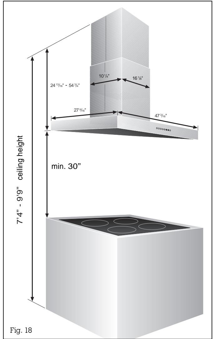
Flexible aluminium pipes, corrosion-protected sheet metal pipes and exhaust air pipes whose material conforms to fire B1 in accordance with DIN 4102 can be used. Exhaust air pipes should have a nominal diameter of 6^ / 150mm .
Pay particular attention to ensuring that
- the exhaust air ducts and pipes are kept as short as possible
- the pipes are not laid at an acute angle, but as bends and that they are inserted into the shaft at an inclined upward angle and
- there are no cross-sectional constrictions in the upward direction (this reduces the volume flow).
If long, rough exhaust-air pipes, many pipe bends or smaller pipe diameters are used, the air extraction rate will no longer be at an optimum level and there will be an increase in noise.
The manufacturer of the extractor hood accepts no liability for complaints which can be attributed to the design and layout of the pipework.
As standard, the blow-out opening of the extractor hood is in the upward direction.
To pass exhaust air through the outer wall, we recommend the use of our telescopic wall box TM 150-045 (Ø 6" / 150 mm).
Note:
To prevent the ingress of water, e.g. condensate or rain water from an uncovered exhaust air shaft, our condensate separator RV 060-150 must be installed in the exhaust air line. The condensate separator must still be accessible after installation.
The duct units listed below are available depending on the height of the ceiling:
Installation accessories for exhaust air mode
Stainless steel-design ventilation duct:
LK 010-016 for ceiling heights of 7^4^ - 7^11^
LK 010-026 for ceiling heights of 7^11^ - 9
LK 010-036 for ceiling heights of 9^ - 9^9^
Aluminium-design ventilation duct:
LK 011-016 for ceiling heights of 7^4^ - 7^11^
LK 011-026 for ceiling heights of 7^11^ - 9
LK 011-036 for ceiling heights of 9^ - 9^9^
Installation accessories for circulating air mode
Stainless steel-design ventilation duct:
LK 010-126 for ceiling heights of 7^11^ - 9
LK 010-136 for ceiling heights of 9^ - 9^9^
Aluminium-design ventilation duct:
LK 011-126 for ceiling heights of 7^11^ - 9^
LK 011-136 for ceiling heights of 9^ - 9^9^
The dimensions above refer to a distance of 5^3^ from the floor to the bottom edge of the hood.
If required, custom made duct units are available at an extra charge.
The electrical socket must be placed within the ventilation duct on the ceiling.
To use above gas cooker / gas hob
Important: do not use all burners on the highest setting simultaneously over a longer period of time (max. 15 minutes). This will pose a risk of burns when touching the hot appliance exterior or parts of the extractor hood may become damaged.
Switch the extractor hood to the highest setting when three or more burners of a gas cooker are used simultaneously.
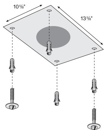
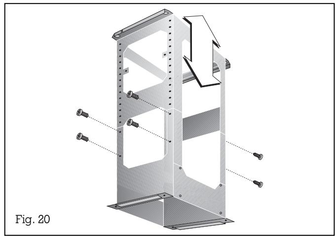
Fig. 19
Note:
the extractor hood is to be installed to a kitchen ceiling or suspended ceiling. Ensure that the ceiling is capable of providing a firm hold for a maximum weight of hood and accessories of 45kg .
Before marking the securing holes, make sure that no electricity wires or water pipes or other wires/ pipes are laid at the drilling points in the ceiling.
Before installation check the enclosed wall plugs and screws are suitable for your ceiling. If necessary use special wall plugs.
Installation of the extractor hood:
- Using the drilling template mark the position of the screws on the ceiling.
- Drill 4 holes 8 mm for the wall plugs. Push the plugs flush with the ceiling (Fig. 19).
- Turn two screws to a 10mm gap. Both screws are placed in a position, in which at a later stage of the installation the key-holes of the supporting frame are found (namely back left and front right from the control panel of the hood).
- Adjust the support frame to the desired height and secure with 8 screws (12 screws for the longer ventilation ducts). The length of the support frame can be adjusted in steps of 20mm (Fig. 20).
Note:
this hood has been approved for installations as low as 30'' and as high as 36'' above the cooktop.
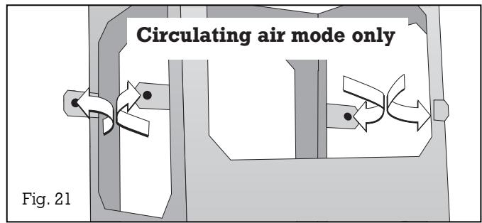
Circulating air mode only: there are four brackets, which fix the circulating air switch module to the top of the support frame. These should be bent outward in a 90^ angle (Fig. 21).
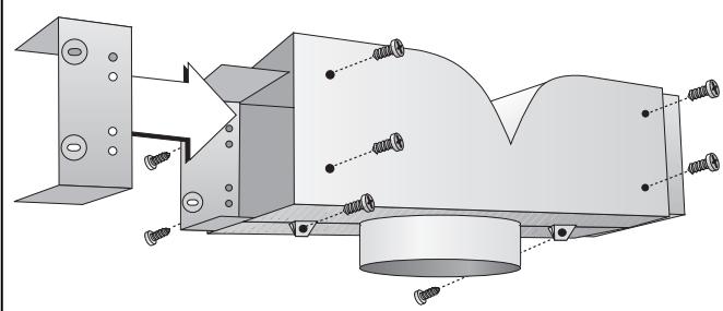
Fig. 22
- Hang the support frame with the two key-holes to the two screws in the ceiling and attach it with all 4 screws to the ceiling. The marking "FRONT" must be on the same side as the control panel after installation.
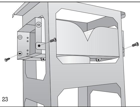
Circulating air mode only: assemble the circulating air switch module and fix it to support frame (Fig. 22 and 23). Cut the flexible air pipe to the required length and fix it to the extractor hood.
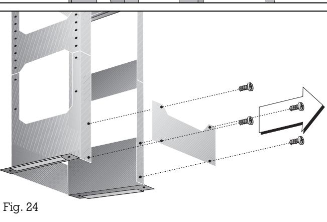
- Remove the cover plate from the rear of the support frame (Fig. 24).
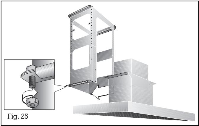
- Slide the extractor hood into the on the side of the support frame (Note: take care not to trap the mains connecting cable) and immediately secure the hood with 4 screws (Fig. 25).
- Screw the cover plate back on the rear of the support frame. The cover plate is important for the stability of the frame.
- Connect the air outlet pipe to the extractor hood and to the exhaust air pipe on the ceiling (to the circulating air switch module for circulating air mode).
- Establish the electrical connection.
- Pull the protective film off the chimney's trims (if applicable).
- Avoid damaging the sensitive surfaces when installing the ventilation ducts.
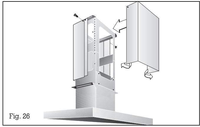
- Secure the top chimney duct unit which has no magnetic strips with 2 screws on the top of the support frame (Fig. 26).
- The second top chimney duct (which has magnetic strips) should be slightly bent open, in order to slide over the first chimney duct easily. Adjust (leave no gap) and fix with 2 screws to the top of the support frame (Fig. 26).
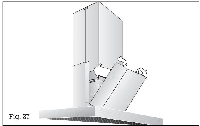
- Place the bottom chimney duct unit which has no magnetic strips on the extractor hood. The second bottom chimney duct (which has magnetic strips) should be slightly bent open, in order to slide over the first chimney duct easily. Adjust to leave no gap (Fig. 27).
- Circulating air mode only: insert the activated charcoal filter (see page 10). The activated charcoal filter is not supplied with the appliance.
- Test that the appliance functions correctly.
Note: only dismantle the chimney ducts by hand. Do not use a tool, this might damage the ventilation ducts.
GAGGENAU
GAGGENAU HAUSGERÄTE GMBH
CARL-WERY-STR. 34·81739 MUNCHEN
GERMANY
(089) 45 90-03
FAX (089) 45 90-23 47
GAGGENAU
780 DEDHAM STREET
CANTON, MA 02021
USA
800.828.9165
www.gaggenau-usa.com