
Venice Cage - Professional video camera Tilta - Free user manual and instructions
Find the device manual for free Venice Cage Tilta in PDF.


| Product type | Protective cage and power distribution system for Sony VENICE |
| Brand | Tilta |
| Model | Venice Cage |
| Compatibility | Sony VENICE |
| Material | Aluminium |
| Battery mount | Gold Mount or V-Mount plate depending on configuration |
| Power input | LEMO 6-pin male connector (ECG.2B.306.CLL) |
| Input voltage | 11.5 - 17 V DC or 22 - 32 V DC |
| Outputs 11.5 - 17 V DC | 2x LEMO 2-pin, 1x P-Tap, 2x Fischer 3-pin |
| Max current on 12 V outputs | 3.0 A per connector |
| 24 V output | 1x Fischer 3-pin, 24 V DC, 2.5 A max |
| TTL serial port | LEMO 7-pin, TX/RX, auxiliary 5 A max |
| Start/stop trigger | Active-low GPI dry contact (short pin 3 to pin 1) |
| Electronic protection | Reverse polarity, ESD, undervoltage, overvoltage, overcurrent |
| Nucleus-M compatibility | Yes, via TTL serial port |
| Accessory mounts | Threaded holes for accessory mounting (1/4'' and 3/8'') |
| Weight | Approximately 0.9 kg |
| Maintenance | Clean with a dry, soft cloth |
| Repairability | Aluminum design, spare parts available |
| Warranty | Standard manufacturer warranty |
Frequently Asked Questions - Venice Cage Tilta
User questions about Venice Cage Tilta
0 question about this device. Answer the ones you know or ask your own.
Ask a new question about this device
Download the instructions for your Professional video camera in PDF format for free! Find your manual Venice Cage - Tilta and take your electronic device back in hand. On this page are published all the documents necessary for the use of your device. Venice Cage by Tilta.
USER MANUAL Venice Cage Tilta
READ BEFORE YOU SHOOT
Read this operation guide carefully and in its entirety before assembling or operating your camera.


Figure: Gold Mount Adapter Plate for VENICE (Left); and V-Mount Adapter Plate for VENICE (Right)
Solid battery adapter made of aluminum. The Power Splitting box is a proven battery solution featuring various industry standard accessory power connectors. The Power Splitting box can be attached to the Battery DC input of VENICE(Square-shaped 5pin connector).
AUXOUT

Figure: Front Face of AUX PWR Connector (Looking at the Camera)
The 2-pin 0B LEMO connector (LEMO EEG.0B.302.CLL) supplies unregulated (+) 11.5 to 17.0 VDC battery pass-through power. The maximum sustained current draw is 3.0 A.
| PIN | SIGNAL | DESCRIPTION | DIRECTION |
| 1 | GROUND | Common ground | N/A |
| 2 | +11.5 to +17 VDC | +11.5 to 17 VDC unregulated battery pass-through power | Out |

Figure: (+) 11.5 to 17.0 VDC RS Connector (Looking at the Connector)
The two (2) Fischer 3-pin 102 connectors supply unregulated (+) 11.5 to 17.0 VDC battery pass-through power. The maximum sustained current draw is 3.0 A. Each connector also includes a start/stop trigger input.
To operate the GPI contact closure style trigger, short Pin 3 (GPI) to Pin 1 (ground).
WARNING: DO NOT apply voltage to Pin 3 (GPI).
| PIN | SIGNAL | DESCRIPTION | DIRECTION |
| 1 | GROUND | Common ground | N/A |
| 2 | +11.5 to +17 VDC | +11.5 to 17 VDC unregulated battery pass-through power | Out |
| 3 | Trigger | Active Low to start/stop record (3.3V pull up) | In |

Figure: 24V RS (Looking at the Connector)
The Battery plate Production Module features one 24V RS (run/stop) connector. The Fischer 3-pin 102 connector supplies a combined 24V power out at a maximum sustained current draw of 2.5A. Each connector also includes a start/stop trigger input.
To operate the GPI contact closure style trigger, short Pin 3 (GPI) to Pin 1 (ground).
WARNING: DO NOT apply voltage to Pin 3 (GPI).
| PIN | SIGNAL | DESCRIPTION | DIRECTION |
| 1 | GROUND | Common ground | N/A |
| 2 | +24 V OUT | +24 V out, 2.5A max (shared between the connectors) | Out |
| 3 | Trigger | Active Low to start/stop record (3.3V pull up) | In |
CONTACT CLOSURE STYLE TRIGGER BUTTON CIRCUIT (24V RS)
The diagram below shows the contact closure style trigger button circuit on the 24V RS connector.

Figure: Contact Closure Style Trigger Button Circuit Diagram (24V RS)
POWER PORTS
Battery DC Input Square-shaped 5pin connector DC IN LEMO ECG.2B.306.CLL 6pin (male)
The 6-pin 2B LEMO connector(LEMO ECG.2B.306.CLL) accepts DC input power from (+)11.5 V DC to 17.0 VDC or (+)22 V DC to 32 VDC. A built-in power conditioner protects against reverse-polarity connections, electrostatic discharge (ESD), undervoltage, overvoltage, and overcurrent.

Figure: Front Face of the DC In Power Input Connector (Looking at the Camera)
| PIN | SIGNAL | DESCRIPTION | DIRECTION |
| 1 | +VBATT Power | input, +12 to +17 V DC/+22 to 32 VDC | In |
| 2 | +VBATT Power | input, +12 to +17 V DC/+22 to 32 VDC | In |
| 3 | GROUND | Power return (camera ground) | N/A |
| 4 | GROUND | Power return (camera ground) | N/A |
| 5 | N/A | No connection (NC) | N/A |
| 6 | N/A | No connection (NC) | N/A |
NOTE: When connecting a cable to a connector, align the key and red marker on the cable connector with the corresponding key and marker on the device connection.

Figure: Tiltta Production TACTICAL TOP PLATE
AUX POWER (P-TAP)

Figure: P-Tap Connector (Looking at Camera)
The AUX power out connector features an industry-standard P-Tap connector and supplies conditioned VBATT at a maximum of 3.0A of power.
| PIN | SIGNAL | DESCRIPTION | DIRECTION |
| 1 | GROUND | Common ground | N/A |
| 2 | +11.5 to +17 VDC | +11.5 to 17 VDC unregulated battery pass-through power | Out |

Figure: Front Face of AUX PWR Connector (Looking at the Camera)
The two (2) 2-pin 0B LEMO connectors (LEMO EEG.0B.302.CLL) supply unregulated (+) 11.5 to 17.0 VDC battery pass-through power. The maximum sustained current draw is 3.0A.
PIN SIGNAL DESCRIPTION DIRECTION
1 GROUND Common ground N/A
2 +11.5 to +17 VDC +11.5 to 17 VDC unregulated battery pass-through power Out

Figure: (+) 11.5 to 17.0 VDC RS Connector (Looking at the Connector)
The two (2) Fischer 3-pin 102 connectors supply unregulated (+) 11.5 to 17.0 VDC battery pass-through power. The maximum sustained current draw is 3.0A. Each connector also includes a start/stop trigger input.
To operate the GPI contact closure style trigger, short Pin 3 (GPI) to Pin 1 (ground).
WARNING: DO NOT apply voltage to Pin 3 (GPI).
| PIN | SIGNAL | DESCRIPTION | DIRECTION |
| 1 | GROUND | Common ground | N/A |
| 2 | +11.5 to +17 VDC | +11.5 to 17 VDC unregulated battery pass-through power | Out |
| 3 | Trigger | Active Low to start/stop record | In |
SERIAL (TTL CONTROL)
The top plate features a SERIAL connector. The 7-pin OB LEMO SERIAL connector supports TTL RX, TTL TX. The connector also offers auxiliary power out, with a maximum sustained current draw of 5.0A. The connector on the cable communicates with Nucleus-M.

Figure: Front Face of the SERIAL (TTL) Connector (Looking at the Camera) SERIAL CONNECTOR
| PIN | SIGNAL | DESCRIPTION | DIRECTION |
| 1 | TTL TX | TTL TX | Out |
| 2 | GND | Camera ground | N/A |
| 3 | N/A | No connection (NC) | N/A |
| 4 | TTL RX | TTL RX | In |
| 5 | AUX OUT | +11.5 to +17 VDC unregulated battery pass-through power | Out |
| 6 | AUX OUT | +11.5 to +17 VDC unregulated battery pass-through power | Out |
| 7 | GND | Camera ground | N/A |



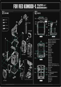

Brand : Tilta
Model : Venice Cage
Category : Professional video camera