
Alde Compact 3030 - TRUMA - Free user manual and instructions
Find the device manual for free Alde Compact 3030 TRUMA in PDF.


User questions about Alde Compact 3030 TRUMA
0 question about this device. Answer the ones you know or ask your own.
Ask a new question about this device
Download the instructions for your in PDF format for free! Find your manual Alde Compact 3030 - TRUMA and take your electronic device back in hand. On this page are published all the documents necessary for the use of your device. Alde Compact 3030 by TRUMA.
USER MANUAL Alde Compact 3030 TRUMA
Alde Compact 3030/3030 Plus
Certified for use in recreational vehicles


© Truma Corp.
All Rights Reserved
Sales
Truma Corp
2800 Harman Dr.
Elkhart, IN 46514
USA
Toll Free 1-855-558-7862
info@trumacorp.com
www.truma.com/us


Operating instructions, page 2.
To be kept in the vehicle. It is part of the heating system.
WARNING
If the information in this manual is not followed exactly, a fire or explosion may result causing property damage, personal injury or loss of life.
- Do not store or use gasoline or other flammable vapors and liquids in the vicinity of this or any other appliance.
WHAT TO DO IF YOU SMELL GAS
- Do not try to light any appliance.
- Do not touch any electrical switch; do not use any phone in your vehicle.
- Immediately call your gas supplier from a neighbor's phone. Follow the gas supplier's instructions.
- If you cannot reach your gas supplier, call the fire department.
- Installation and service must be performed by a qualified installer, service agency or the gas supplier.


Your safety and that of others is of the utmost importance. Always read and follow all safety instructions carefully.

All safety information in the manual is marked with this symbol.
All safety instructions are indicated by the safety symbol and the word “DANGER”, “WARNING”, “CAUTION” or “NOTICE!”.
Word definitions:
DANGER An imminently dangerous situation that will result in death or serious injury.
WARNING A potentially dangerous situation which may result in death or serious injury and/or damage to property.
⚠️ CAUTION A potentially dangerous situation that can lead to minor or moderate injury.
NOTICE Requires attention to follow a specific procedure or maintain a specific condition.
SAFETY WARNINGS
DANGER CARBON MONOXIDE POISONING
- The heating system can generate dangerous carbon monoxide (CO) when using LP gas as fuel, if not installed and/or used correctly.
- To avoid suffocation accidents, always use the system's LP gas fuel outdoors to ensure exhaust gases are dispersed. Never use in a confined space, and never inhale exhaust gases.
- Ensure that the gas exhaust is placed outdoors, and never under the vehicle's awning or under a canopy, for example.
- Never use the system without adequate ventilation.
- Ensure that the air inlet and exhaust outlet are not blocked.
- Never allow water to enter the system when cleaning the vehicle. If using a high pressure washer, for example, never spray directly into the system's exhaust outlet.
WARNING RISK OF FIRE OR EXPLOSION
- Never operate the system while filling the LP gas tank.
- Never use open flame when checking for gas leaks.
• Always use original parts from Alde. - LP gas tanks must only be filled by qualified gas suppliers.
- Only use LP gas.
WARNING
The freshwater in the boiler should always be drained during extended breaks and when there is risk of frost, otherwise there is a risk of damage due to the boiler freezing. The warranty does not cover frost damage.
WARNING HOT WATER
High water temperature above 120\ °F ( 49\ °C ) can cause serious scalding, and in extreme cases even death. The heating system can supply water at a temperature above 185\ °F ( 85\ °C ).
- A Thermostatic mixing valve must be fitted to prevent excessively hot water from reaching the taps; part number 3102003. Applies to Alde Compact 3030 Plus.
- Always use a Thermostatic mixing valve set at a temperature that cannot exceed 118 °F (48 °C) for safe operation.
• Always check the water temperature before taking a shower or bath. - Hot water can be dangerous, especially for babies, children, the elderly and the sick.
How long can the skin be exposed to hot water?
| Temperature °F (°C) | Time before skin injuries occur | |
| 158 (70) | Extreme danger! | < 1 second |
| 151 (66) | Very dangerous! | 1-5 seconds |
| 140 (60) | Danger! | < 10 seconds |
| 129 (54) | < 30 seconds | |
| 126 (52) | Warning! | 2 minutes |
| 120 (49) | 5–10 minutes | |
| 100 (38) | Safe | Safe bathing temperature |
Source: Moritz, A.R./Herriques, F.C.: Studies of thermal injuries: the relative importance of time and surface temperature in causation of Cutaneous burns A. J. Pathol 1947; 23: 695–720.
- Before using the hot water tap or shower, let the water run until the temperature is safe and stabilised.
- Check the water temperature before letting a child use the bathtub or shower.
- Never allow a child or a disabled person to bathe unattended.
WARNING
Hot water from the boiler is not intended as drinking water or for preparing food.
CAUTION
- Damage to the heating system may void your warranty.
- Do not make any modifications! Any modifications made to the system or its controls may cause unforeseen serious risks, and void your warranty.
NOTICE
The output temperature from the system and the temperature in the tap can differ, depending on water conditions and length of pipe to the system.
California Proposition 65 lists chemical substances known to the state to cause cancer, birth defects, death, serious illness or other reproductive harm. This product may contain such substances, be their origin from fuel combustion (gas) or components of the product itself.
TABLE OF CONTENTS
-
Intended use 5
-
Safety instructions 5
-
Important information 6
3.1 Use of the heating system 6
3.2 Winter and sub-zero temperatures 6
3.3 The Glycol fluid in the heating system 7
3.4 External factors that may affect the heating system 7
3.5 Convection 7
- Initial operation of the heating system 8
4.1 Pre-operation check of the heating system 8
4.2 Using the water heater 9
4.2.1 Filling the water tank 9
-
Setting up the heating system for the first time 10
-
Review of Alde Control Panel 12
6.1 Switching the boiler on and off 12
6.2 Status screen 12
6.3 Set the desired temperature 13
6.4 Hot water 13
6.5 Energy sources 14
6.6 Settings menu 15
- Care and maintenance 17
7.1 Replacement of the air cushion 17
7.2 Emptying water heaters and water pipes 17
7.3 Glycol fluid 18
7.3.1 Refill the heating system with Glycol fluid 18
7.4 Bleeding the heating system 19
- Error messages 20
8.1 If a fault persists 21
8.2 Operating messages 21
-
Troubleshooting 22
-
Service menu & resetting 23
-
Technical description of the heating system 24
11.1 Operation on LP gas 25
11.2 Operation on electricity 25
MANUFACTURER'S LIMITED WARRANTY 50
WARNING
Always read and follow these instructions before installing and/or using the system.
Take extra care when children are present. Children must not be allowed to play with the product, and must not take part in cleaning or maintenance.
1. INTENDED USE
The Alde Compact 3030/3030 Plus heating system is intended for heating of recreational vehicles. Recreational vehicles (RVs) are designed as temporary living quarters for recreation, traveland/or camping. Recreational vehicles have their own power or are towed by another vehicle. Alde Compact 3030/3030 Plus heating systems each consist of a gas/electric boiler and convectors, using a single zone/dual zone system to set one or two different temperatures in the vehicle. The system supplies the convectors with heat by circulating a glycol mixture, which is heated up using gas and/or electricity in the boiler.
These instructions explain how to use the Alde Compact 3030/3030 Plus heating systems and control panels in recreational vehicles. Installation and repairs may only be carried out by trained professionals, a person whom has been educated in installing and/or servicing the Alde boiler.
This heating system must be installed in accordance with local codes if any; if not, follow ANSI Z223.1/NFPA 1192 or CAN/CSA B149.1, Natural Gas and Propane Installation Code, as applicable.
We reserve the right to make changes after this operating manual has been printed.
Alde International Systems AB
Truma Service
2. SAFETY INSTRUCTIONS
The system is fitted with the following safety devices:
Flame monitor
If the gas flame goes out, a flame sensor shuts off the gas supply.
Low current shut-off
If the current drops below 10.5 V DC, the gas supply to the burner is shut off.
Exhaust fan monitor
In the event of a faulty exhaust fan, the gas supply to the system is shut off.
Monitoring boiler temperature
A temperature switch turns the boiler off if the temperature in the boiler exceeds 194° F ( 90° C).
3. IMPORTANT INFORMATION
WARNING
Close the main LP gas tap in the following circumstances:
- In the event of suspected leakage in the LP gas system.
- When the vehicle is not in use.
- Depending on national legislation, the LP gas main tap shall be closed while the vehicle is in service.
3.1 USE OF THE HEATING SYSTEM
- Always turn off the main switch (12 V) in the vehicle when it's not in use.
- The LP gas burner must not be running when refuelling the vehicle or when filling a solid LP gas tank.
3.2 WINTER AND SUB-ZERO TEMPERATURES
WARNING
ASPHYXIATION HAZARD
For proper and safe combustion, the LP gas burner in the heating system must have sufficient air intake. Insufficient air intake can cause build-up of carbon monoxide which presents an asphyxiation hazard. The induction air for the gas burner enters via the wall cowl, which is usually installed on the side of the vehicle near the boiler.
Do not start the heating system on LP gas before the wall cowl is completely free of snow and ice.
- During winter camping, make sure that the wall cowl and exhaust valves are kept free of snow and ice. There is a Condensate spout (Fig 1, part no. 3010697) for the wall cowl. Note that condensation conductors must not be used while travelling.

Fig. 1. The Condensate spout just clicks onto the wall cowl.
3.3 THE GLYCOL FLUID IN THE HEATING SYSTEM
- Never leave the heating system without glycol mixture.
- Always maintain the correct amount of glycol mixture in the heating system. The heating system must be filled with a mixture of distilled water and glycol. Use only high quality ready-mixed glycol (with inhibitor) intended for aluminum heating systems. The heat transfer medium must be Propylene glycol based boiler antifreeze. If you are using concentrated glycol, the mixture should consist of 50% distilled water and 50% glycol.
- The glycol mixture should be replaced every two years as properties such as corrosion protection deteriorate over time. If the glycol fluid is not replaced at appropriate intervals, there is a risk of frost damage, corrosion, bacterial growth and/or overheating.
The antifreeze must meet FDA (GRAS) standards or be non-toxic fluid having a toxicity rating or class of 1, as listed in Clinical Toxicology of Commercial Products, 5th ed.
- Air pockets can form in the system; a sign of the formation of air pockets is that the pipes only heat up along the first 3-6,6 ft (1-2 meters) proximal to the boiler, even though the circulation pump is running. For more information on bleeding of the heating system, see section 7.4 Bleeding the heating system, page 19.
3.4. EXTERNAL FACTORS THAT MAY AFFECT THE HEATING SYSTEM
- Cleaning fluids for the water system should be used with care as they may cause corrosion of the stainless steel parts of the heating system. Make sure that the detergent you are using works for stainless steel systems. Rinse the system thoroughly before using the heating system again.
- Take note of hard water. Hard water is water that has high levels of minerals, chlorine, lime, and salt. If the boiler is being used in a region with hard water, a water filter is recommended. Hard water can cause lime deposits that may cause impaired function and rust formation.
- To avoid damage, make sure no spray water enters the Alde system when cleaning the recreational vehicles, e.g., do not spray directly into the wall cowl.
3.5 CONVECTION
To make the most efficient use of hydronic heating, air must pass freely through air gaps under the bed boxes, behind the backrests/cushions and wall cabinets. If the vehicle has e.g. fitted carpets, check that they do not prevent air supply to the convectors. It is also important that curtains, cushions and blankets do not prevent air circulation behind seatback cushions and wall cabinets; see Fig. 2.


Fig. 2. Convection
CAUTION HOT SURFACES
Always avoid hot surfaces, marked red when the heating system is in operation.

Alde Compact Boiler 3030/3030 Plus
Never use the system while under the influence of alcohol, drugs or medicines, and always carefully follow the safety instructions.
4.1. PRE-OPERATION CHECK OF THE HEATING SYSTEM
- Check that the glycol mixture is at the right level in the system's expansion tank, see Fig. 3.
The level should be 0.4 in (1 cm) above the MIN mark in cold systems. Ensure that the system is properly filled and bled before putting it into use. - Check that the wall cowl is kept free of ice and snow, as induction air enters the boiler via the wall cowl when run on LP gas. Also check that no other objects block or interfere with exhaust gases and supply air at the wall cowl.

Fig. 3. Expansion tank, dual flow

Expansion tank, single flow
4.2. USING THE WATER HEATER
The Alde Compact 3030/3030 Plus heating system has a built-in hot water heater.
You may use the heating system to heat the recreational vehicles without filling the hot water boiler. When only hot water is required (for example during the summer), no settings need to be changed. The heating system will handle this function automatically.
WARNING SCALDING HAZARD
Remember, the water in the water heater may be very hot.
WARNING FREEZING RISK
Always drain freshwater from the boiler when there is a risk of frost to prevent the boiler from freezing. The warranty does not cover damage caused by freezing.
WARNING
Hot water from the boiler is not intended for drinking or use in food preparation.
CAUTION
Avoid using the Boost and Autoboost functions in your Alde Compact 3030 Plus when the water heater is empty. The water heater must always be full of water when using Boost/Autoboost.
4.2.1 FILLING THE WATER TANK
Procedure:
- Make sure that the vehicle water tank is filled with clean and uncontaminated water, or that it is connected to a city water connection.
- Fill the hot water tank in the heating system with water from the vehicle's water tank by opening any tap and setting it to run hot, then flush until water flows freely.
If the heating system is used for the first time or if the heating system has not been used for some time, flush out the water tank by opening any hot water tap in the recreational vehicles and allowing approximately 3 gallons (12 liters) to run through the tap. - Close all taps and start the heating system.
5. SETTING UP THE HEATING SYSTEM FOR THE FIRST TIME
Setting up the heating system is normally done by the manufacturers.
- Start the heating system by pressing the On/Off button on the control panel (Fig. 5, item 1). When the heating system and control panel are on, a green diode lights up on the On/Off button.
- Select language.
- Press the Configure button to go to System Configuration. You can always reach this menu by pressing the menu button on the Alde Control Panel and scrolling until the System Configuration option arrives (Fig. 4).
- If you have a dual zone system, go to the second page in System Configuration and select 2-zone mode (Fig. 7 och 8).
The relevant function can be selected from the menu:
| Booster fan | Alde AquaClear (only available in certain markets) | ||
| Underfloor heating, 12 V pump for underfloor heating | DuoControl, Bottle Switch (only available in certain markets) | ||
| Engine pre-heat. Heat the engine using the Alde heating system | Remote Control (ex. Alde Voice Control, Alde Control | ||
| Extra hot water tank/Alde Flow, for increased hot water capacity and continuous hot water. (Not 3030 Plus) (only available in certain markets) | 2 zone mode (if you have two temperature zones installed) |

Fig. 4 System configuration
5. ZONE-SETUP SINGLE OR DUO
5.1. Single-zone system
- Browse through System configuration by pressing the arrow in the right corner (Fig. 5, item 3), activate any accessories/functions fitted using their respective menus. (Fig. 5)
- Go back using the Back arrow in the top left corner (Fig. 5, item 2) and select Done.
- To change the desired indoor temperature from the status screen, press the menu button until you reach the temperature setting menu and set the temperature there (Fig. 6). Raise or lower the temperature using the plus and minus buttons.

Fig. 5. Single zone, System configuration

Fig. 6. Single zone
5.2. Dual zone system
- Go to the respective zone and select the name of the zone that corresponds to where its temperature sensor is located, (e.g. Bedroom), and then select whether a booster is installed in the zone.
- If unsure of the zone's name, blow on the sensor in the zone and then look on the control panel for a zone whose temperature has changed.
- Activate the other accessories/functions installed via their respective menus.
- Go back using the back arrow in the left corner (Fig. 7, item 1) and select Done.
-
To change the indoor temperature from the status screen, press the respective zone icons, e.g. "Living room" or "Bedroom". Raise or lower the temperature using the plus and minus buttons. (Fig. 9).
-
Set the time and day by touching the time icon top right of the status screen (Fig 6, item 1).
-
Press the Energy icon on the status screen (Fig. 9) to select operating mode (gas and/or electricity).
Regardless of the energy choice, the boiler will not use more energy than it needs, so select the highest setting possible.
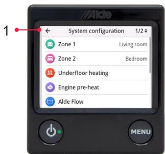
Fig. 7. Dual zone

Fig. 8. Dual zone
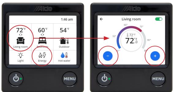
Fig. 9. Dual zone, set the temperature and select gas and/or electricity under Energy.
6. REVIEW OF ALDE CONTROL PANEL
6.1. SWITCHING THE BOILER ON AND OFF
To start the boiler, press the control panel On/Off button (Fig. 10, item 1). The start icon appears (Fig. 10, item 2) and the system starts with the last selected settings. When the heating system and control panel are on, a green diode lights up on the On/Off button. To turn off the heating system, press the on/off button. The control panel and LED will go out.
On/Off button

Fig. 10. Control Panel
1. System switched off, LED out

- System starting, LED lit

- Night mode, Dark status page
6.2 STATUS SCREEN
NOTICE
If the status page (Fig 10, item 3) is set to Dark, the control panel will go dark 30 seconds after it enters sleep mode, but will come on again when the screen is touched. Read more under section 6.6. Settings menu, page 15.
When the control panel is in sleep mode, the status screen (Fig 11, item 1, item 2) is shown. Press the relevant status screen icon to reach its sub menu. Press the menu button to reach the settings menu.
Features marked with asterisks (*) are optical accessories.
Icon description for the status screen's top row (Figs. 11, item 1, item 2)

Operating messages. Displayed if temporary service interruption occurs; this is not an error. Await. Read more in section 8.2 Operating messages, page 21.

Information. Flashes when there is an information message.

120 V AC. Electricity (120 V) is connected to the boiler.

Day Mode. Shows when the function is activated, and turns green when it is automatically switched on.

Night Mode. Shows when the function is activated, and turns green when it is switched on automatically later.

LPG bottle full/empty*. Appears if a DuoControl is installed. Black bottle = LPG available. Red bottle = LPG bottle empty. (only available in certain markets)

Engine heating*. Shows when engine heating is activated, and turns green when it is automatically switched on.

Anti-bacteria. The boiler's automatic bacterial elimination setting is running.

High altitude mode. Flashes if high altitude mode is activated.

Alde AquaClear UV-C*. Shows when the fresh water pump is running and the water filter is functioning. Only available in certain markets.
Footnote. Features marked with asterisks (*) are optional accessories.

Fig. 11, item 1. Status screen, single-zone system
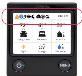
Fig. 11, item 2. Status screen, dual-zone system
Icon description for the status screen's main menu (Figs. 12, item 1, item 2)

Single zone system. Indoor temperature. Displays the current temperature and whether the circulation pump is active(○). Tap the House/Indoor icon to change the desired temperature.
Dual zone system. Zone icons. Displays the current temperature and whether the circulation pump is active in the zone ( ). Tap the House/Indoor icon to change the desired temperature.

Light*. Start, turn off, or dim the AC lighting (only with Truma AC).

Energy. Shows the energy source used; the flame turns red when gas is in use, and the flash turns yellow when electricity is in use. Tap the icon to select and prioritise energy source, and to set load monitor* and high altitude mode.

Hot water. Shows if hot water production is set to off, on or boost. The thermometer is fully coloured-in when hot water reaches boost temperature. Press the icon to select hot water mode, (off, on, boost or auto (3030 PLUS). Read more in section 6.4 Hot water, page 13.

Outdoor temperature*. If an outdoor sensor is installed, the current outdoor temperature is displayed.
Footnote. Features marked with asterisks (*) are optional accessories.
6.3 SET THE DESIRED TEMPERATURE
The room temperature can be set from +41°F ( +5°C ) to +86°F ( +30°C ) in increments of 1°F ( 0.5°C ).
For 1 zone, set the temperature by pressing directly on the plus and minus buttons.
For 2 zones, press the icon for the zone you wish to set the temperature in.
The temperature displayed (Fig. 13) is the current temperature setting.
To leave the menu, tap the menu button.
6.4 HOT WATER
WARNING SCALDING HAZARD
When the hot water and glycol mixture in the boiler are heated at the same time, the hot water can become very hot in the event of a significant heating requirement.
The boiler has a built-in hot water heater with a volume of around 3 gallons (10 litres). The boiler can be used even without fresh water being in the water heater.
There are three different hot water settings: no hot water, normal operation and boost (priority hot water) (Fig. 14, item 1); the 3030 Plus also has Autoboost/Auto mode (Fig. 14, item 2).
- Off - Hot water off. The hot water may still be hot if there is a heating requirement in the vehicle and if there is fresh water in the system.
- On - Hot water switched on.
- Boost - Priority hot water production. The boiler will now prioritise and increase the production of hot water for 30 minutes. When 30 minutes have passed, the boiler returns to its previous setting. Prioritised hot water production is recommended for increased hot water demand. If you don't get enough warm water, turn on the gas and all allowed electric power.
- Autoboost/Auto - Hot water switched on and goes automatically to Boost as required. Auto is only available in 3030 Plus.

Fig. 12, item 1. Main menus on the status screen, single-zone system

Fig. 12, item 2. Main menus on the status screen, dual-zone system

Fig. 13. Set temperature

Fig. 14, item 1. Set hot water production, Alde Compact 3030

Fig. 14, item 2. Set hot water production, Alde Compact 3030 Plus
6.5 ENERGY SOURCES
The boiler can be powered either by LP gas or electricity, or both simultaneously. When the boiler approaches the set temperature, energy consumption is gradually reduced. Press Energy (Fig 15, item 1) to reach energy settings. There are two pages (Fig 15, item 2, item 3) for setting energy; they can be reached either by pressing the numerals in the top right corner or by scrolling up or down.

Fig. 15. Choice of energy sources


Warming up with electricity
The menu selection is max permissible consumption, i.e. the boiler will not use more power than necessary, even if e.g. 1,9 kW is selected in the control panel (Fig 16, item 1, item 2).
Warming up with gas
Press the control on the gas menu line to start and stop LP gas operation (See Fig.16, item 2).
Priority
It is also possible to prioritise the energy source (Fig. 17, item 1, item 2). When both LP gas and electricity are switched on, select the priority energy source. If the priority energy source is insufficient, both will be activated.
Load monitor*
To prevent tripping the 120 V circuit breaker when the vehicle is connected to an electricity pole, use the load monitor (Fig 18, item 1). Set the voltage to the same voltage as the electrical pole's circuit breaker (Fig 18, item 2). Always set the power to 1,9 kW on the panel. If a load monitor is installed, power on the panel need not be changed when the vehicle is connected to a new electricity pole; only change the load monitor value. The boiler and Truma AC connected to the Alde system will automatically reduce their consumption when e.g. a toaster or hairdryer is switched on.
High altitude mode
Only use high-altitude mode if the boiler will be run on LP gas at altitudes above 3280 ft (1000 metres amsl). For high-altitude LP gas operation, use propane to ensure stable combustion. Varied operating conditions at high altitudes may cause the boiler to not always reach full gas operation.
Press the control on the High-altitude mode menu row to adapt gas operation accordingly (Fig.19).


Fig. 16. Energy, set electricity and/or gas


Fig. 17. Priority, electricity or gas
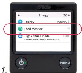

Fig. 18. Load Monitor

Fig. 19. High-altitude mode
6.6 SETTINGS MENU
To reach the Settings menu from the sleep/standby screen, press the menu button to get it started. The Settings menu provides the following features:
Settings menu, Fig. 20

Night Mode. Automatically changes select features during the night. Choose the time interval and whether it should be done every night or a specific night each week. The following can be changed: temperature, status screen light, putting AC* into night operation and changing room sensors*, turning off hot water production, and underfloor heating*.

Day Mode. Automatically changes select features throughout the day. Choose the time interval and whether it should be done every day or a specific day each week. The following can be changed: temperature and hot water production.

AC* (Truma only). Start or turn off automatic climate setting (=AC and the heating system work together); for dual-zone installation, choose which zone the AC should follow.

Underfloor heating*, Underfloor heating. Turn the underfloor heating on or off. Select continuous operation of the underfloor heating by activating "Continuous".

Engine pre-heat*. Heat the engine using the Alde heating system. Start or turn off the function, select the start time and the engine heating duration.
Settings menu, Fig. 21

Pump in constant operation. (Only Alde Compact 3030/3030 Plus 1-zone system)

Delayed start, automatic boiler start. Start or turn off the feature, select start and end time. For the function to work, the boiler must be switched off.

External start. This function is used when starting the heating system from outside the vehicle. When external start has been activated, the control panel must be turned off. External start has three modes, Off, Ext and 120 V. In the Off mode the function is turned off.
External start*. This function is used when starting the heating system through an external signal. When the External start function has been activated, the control panel must be turned off, but a 12 V power source has to be connected. The desired parameters/functions for the heating system when it starts have to be set before turning off the control panel. This function requires installation of an accessory for External starts (part no. 3030219).
120 V. This function is used to start the heating system when a 120 V power source is connected to the vehicle from outside. When the 120 V function has been activated, the control panel must be turned off but a 12 V power source has to be connected. The desired parameters/functions for the heating when it starts have to be set before turning off the control panel. (120 V connected).

Temp sensor calibration, offset for temperature sensor. The temperature can be adjusted ±10\ °F ( ±5\ °C ) if you feel the temperature sensor needs adjusting. Also applies to outdoor temperature sensor.
Settings menu, Fig. 22

Display. Select panel brightness: Low, Medium, or High. You can also choose whether the status screen should be Normal, Inverted, or Dark. If Dark is selected, the panel will go dark after 30 seconds and will light up again if touched.

Fig. 20. Settings menu

Fig. 21. Settings menu

Fig. 22. Settings menu
Settings menu, Fig. 22

Sound. Start or turn off button and warning/notification sounds.

Language. Change the language in the Control Panel menus; available languages are: English, German and French.

Service. Displays values from the heating system; these are updated continuously and describe the current status of the boiler. See section 10, Service Menu & Reset, page 23.

System configuration, enable installed accessories and features. Here, you will find all accessories or functions that can be connected to the Alde Heating System; tick the features that are installed in the heating system to enable their use.

Reset. Resets the panel to factory setting. The accessories/features selected under System Configuration are not affected.
Footnote. Features marked with asterisks (*) are accessories.

Fig. 22. Settings menu
7. CARE AND MAINTENANCE
CAUTION
Only install specially adapted hoses and gaskets approved for use with LP gas. The use of other types of hoses can lead to hose breakage and leakage. Hoses and gaskets must be replaced in accordance with national regulations and by a trained professional.
NOTICE
Have the LP gas system checked regularly, preferably once a year, to ensure that couplings and hoses are tightly fitted.
LP gas hoses should be replaced according to the date marking of the hose when they dry out and crack, resulting in possible leakage.
- Turn off the main power supply (12 V) to the heating system when not in use. The main power supply should always be switched off when the vehicle is not in use.
- Close the tap on the LP gas bottle/tank.
7.1 REPLACEMENT OF THE AIR CUSHION
The heating system is designed to have air space, a so-called air cushion, at the top of the hot water tank. The air cushion is absolutely necessary to enable the expansion of the water when heated, but also to absorb any pressure shocks caused by the water pump in the heating system.
Always replace the air cushion in the heating system after 14 days of use. Do this by turning off the fresh water pump and opening the heating system safety/drain valve for a few seconds (Fig. 23 depending on the valve fitted to the vehicle). When the air cushion needs to be replaced, a message appears on the control panel.

Fig. 23. Safety valve/drain valve
7.2. EMPTYING OF WATER HEATERS AND WATER PIPES
WARNING SCALDING HAZARD
Remember, the water in the water heater may be hot.
NOTICE
Check that the automatic non-return valve opens and lets air into the boiler when draining, and check that the hose is not clogged.

- Switch off the fresh water pump.
- Open all water taps to the central position so that both hot and cold water run out.
- Open all safety/drain valves or, depending on your system, move the yellow handle into a vertical position (fig 23).
- Make sure all water runs out approx 2-3 gallons (7-10 litres). Allow the valves to remain open until the heater is used again.
- Reset all safety/drain valves by closing the handle.
When emptying other water systems in the vehicle, refer to the manufacturer's instructions for use.
7.3 GLYCOL FLUID
WARNING POISONING
Be sure to thoroughly dry any puddles of leaked glycol or glycol fluid. Rinse the area with water and dry up the excess to prevent children or pets from ingesting glycol.
CAUTION
The heating system comes with glycol mixture within. If the fluid level is too low, the system must be filled up to the correct level before using the heating system. The warranty can be voided and the heating system may be damaged upon start-up with too little or no glycol mixture.
NOTICE
Do not mix different types of glycol, as this can cause coagulation of the glycol mixture.
NOTICE
If the glycol fluid is not replaced at appropriate intervals, there is a risk of frost damage, corrosion, bacterial growth and/or overheating.
The heating system must be filled with a mixture of distilled water and glycol. Use only high quality ready-mixed glycol (with inhibitor) intended for aluminum heating systems. The heat transfer medium must be Propylene glycol based boiler antifreeze. The antifreeze must meet FDA (GRAS) standards or be non-toxic fluid having a toxicity rating or class of 1, as listed in Clinical Toxicology of Commercial Products, 5th ed. When using concentrated glycol, the mixture must consist of 50% distilled water, or water with no salt content, and 50% glycol. The use of tap water may cause corrosion and affect the warranty.
If the system is exposed to temperatures lower than -13°F (-25°C), glycol content must be increased, but must not exceed 50%.
The glycol mixture must be changed every two years, as properties such as corrosion protection degrade.
7.3.1 REFILL THE HEATING SYSTEM WITH GLYCOL FLUID
Glycol content should be checked at the expansion tank using a glycol tester before refill, to ensure that the concentration of glycol in the fluid is not too high. If the fluid level has dropped for reasons other than evaporation, check all joints, rubber hoses, drain taps and air screws for leakage before filling.
The glycol system is manually replenished in the expansion tank. When manually filling, slowly pour the glycol mixture into the expansion tank. The level must be approx. 0.4 in (1 cm) above the MIN line (Fig. 24) when the system is cold.
Bleed both zones in a dual-zone system after filling; add more glycol mixture if the glycol level drops during bleeding.
Bleed a newly filled system after each use for the first month, then monthly, is recommended.

Fig. 24. Expansion tank
7.4 BLEEDING THE HEATING SYSTEM
When filling glycol mixture into the system, air pockets may form, depending on how the piping system is installed. A sign of air in the system is that only the first few metres of the pipes extending from the boiler heat up, even though the circulation pump is running.
In newly filled heating system, small air bubbles can form in the expansion tank, creating a gurgling sound. If the circulation pump is stopped for a few seconds, the bubbles will usually disappear; however, if the problem persists, bleed the heating system to remedy the problem.
WARNING SCALDING HAZARD
Remember: the glycol mixture can be very hot.
NOTICE
Never open the bleed screws while the pump is running, as this may allow air into the system.
To bleed the system:
- Boiler must be switched off.
- If the boiler is equipped with a bleed screw on the output pipe, open the screw and leave it open until fluid comes out. Proceed to step 4.
- If the boiler is fitted with automatic bleeder, bleeding will be performed automatically. Start the boiler and let the fluid circulate in the system until it is bled. Top up with fluid if necessary in accordance with step 5. If this does not help, turn off the boiler and go to step 4.
- Open the other bleed screws in the system one by one. Leave them open until glycol mixture comes out of them, then close them.
- Check the fluid level in the expansion tank. Top up if the level has dropped after ventilation. The fluid level in the expansion tank must lie 0.4 in (1 cm) above the min. line (fig. 24) when the system is cold.
- Start the boiler and allow to run until the pipes and convector's around the vehicle are heating up (Normal setting, speed 2. Bleeding, speed 5). If they are hot, venting is complete, otherwise proceed to step 7.
- Put the pump(s), in speed position 5. Turn off electricity and gas. Set the heat to 86°F (30 °C) and let the boiler run for 5 minutes. Next, begin again at step 1.
Single axle trailer/motor home or twin axle trailers
NOTICE OVERHEATING
- Check that the system is properly ventilated.
-
Never use full electricity or gas capacity until the system is properly bled.
-
Stop the circulation pump.
- Lower the front of the caravan as far as possible. Let it stand for a few minutes, so that the air can move upwards in the heating system.
- Open the bleed screw at the highest point. Leave it open until glycol mixture runs out.
- Raise the front of the caravan as far as possible and repeat step 3.
- Place the caravan in a horizontal position and start the circulation pump.
- Check that the pipes and convectors around the vehicle are heating up.
It is easiest to bleed air from the heating system with the vehicle on a sloping surface, or with one end of the vehicle suspended by a jack. Bleed air from the heating system on a slope as described for the single-axle caravan above. Alternatively, the heating system can be aerated with a filling pump at a workshop; contact Alde Service Partner or Truma Corp.
8. ERROR MESSAGES
When an error message appears on the Control panel, the LED on the On/Off button changes to solid red.
Connector failure: Check the red cable between the boiler and the panel and its red connectors. Also check cables connected to the black connector of the boiler, e.g. cable between AC and boiler or panel.
Heater not found: There is a connection fault between the boiler and the control panel. Most likely a problem with the boiler circuit board; contact your dealer. The fault may also be due to incompatible software in the boiler and panel.
Overheat glycol: This fault can occur if the boiler is running at high power while there are air pockets in the system; ventilate the heating system properly. Also check that the fluid level in the expansion tank is at least 0.5 in (1 cm) above the MIN mark when the fluid is cold. It can also occur if the circulation pump has broken or is disconnected from the boiler. To restore the fault, the glycol temperature must drop to below 122° F ( 50° C). Once this happens, remove, then reconnect 12 V to the boiler.
Overheat lockout: There has been an episode of overheating in the boiler. The temperature has gone down but the boiler is still locked. To reset the fault, disconnect, then reconnect, 12 V to the boiler.
Overheat PCB: Overheating in the boiler or boiler compartment. To reset the error, the temperature in the pan must first drop. Disconnect, then reconnect 12 V to the boiler. If this does not help, contact Alde Service Partner or Truma Corp.
Heater failure: The circuit board is damaged. To reset the fault, disconnect, then reconnect 12 V to the boiler. If the error persists, contact Alde Service Partner or Truma Corp.
Low battery voltage: If the vehicle's battery voltage to the boiler is less than 10.8 V, the boiler stops. This resets automatically when the voltage reaches 11 V. If the voltage is lower, other error messages may also appear. These error messages occur only because the battery voltage is/has been too low and are therefore not true malfunctions. Ensure that the boiler gets the right voltage for the right function.
Gas failure: Ensure that gas is available to the boiler. To reset the fault, disconnect and reconnect the 12 V supply to the boiler. When the supply is reconnected, gas operation must be reactivated in the control panel. The fault may also be due to a defective spark generator and/or burner; contact Alde Service Partner or Truma Corp if the fault persists.
Fan failure: The combustion fan is defective. Contact Alde Service Partner or Truma Corp.
Window open: A window switch indicates that a window near the wall flue is open, the boiler stops running on gas. Gas operation restarts when the window is closed. Electric operation still works.
Panel failure: May occur if the panel has been exposed to high humidity for a long time. Make sure the panel is dried, then restart. If the error persists, contact Alde Service Partner or Truma Corp.
Opt. dongle not found: A previously identified option card is missing from the boiler. Make sure it is connected or uninstall the accessories that require it. In order for the system to find the option card again, disconnect 12 V from the boiler, plug in the option card, and then reconnect 12 V. If the error persists, contact Alde Service Partner or Truma Corp.
Load monitor not found: A previously identified load monitor is missing from the boiler. It is either disconnected or defective. Make sure that the load monitor is plugged in; if the fault persists even though the load monitor is plugged in, contact Alde Service Partner or Truma Corp.
Zone 1 sensor error/Zone 2 sensor error: The room sensor in zone 1 or zone 2, e.g. by sofa or bed, is disconnected or defective. Check that the sensor is plugged in and that neither the sensor nor the cable is defective. If the error persists, contact Alde Service Partner or Truma Corp.
Hot water sensor error: The hot water sensor is disconnected or defective. If the error persists, contact Alde Service Partner or Truma Corp. The boiler continues to work but does not actively produce hot water; however, the water can still get hot if the boiler produces heat.
Outdoor sensor error: The outdoor temperature sensor is disconnected or defective. If it has been disconnected, please press the "dismiss" button in the control panel.
CI-bus error: High communication load on the yellow connector of the control panel. Check the cable, couplings, and your vehicle's master panel. If the error persists, contact Alde Service Partner or Truma Corp.
Remote Control error: Remote control connected to the JP3 connector on the back of the Control Panel is disconnected or defective. Check cable and couplings. If it has been disconnected, press the "uninstall" button on the control panel.
8.1 IF A FAULT PERSISTS

Fig. 25. Couplings on the boiler circuit board
Disconnect 12 V from the boiler by disconnecting the cable that supplies the boiler from the boiler circuit board. This cable is located at the top left of the circuit board. Reconnect 12 V by reconnecting the cable.
If a fault persists even after disconnecting and reconnecting 12 V to the boiler, please also disconnect 120 V and then 12 V again. Reconnect 120 V and 12 V. If this doesn't help, contact your dealer or Alde Service Partner/Truma Corp.
8.2. OPERATING MESSAGES
An operating message is not a fault but a temporary service interruption. If an error occurs, an error message will appear on the screen.
Fan restarts...:
The combustion fan did not reach sufficient speed. A new start attempt will be made within a few minutes. This is not a fault. If "Fan failure" appears after several "Fan restarts...", then a fault has occurred. Please wait for as long as "Fan restarts..." appears.
Full gas power unavailable:
The combustion fan did not reach sufficient speed for full gas operation. This can occur if "High Altitude Mode" is turned on; read more about this feature in section 6.5 Energy sources, page 14.
If the message arrives without High Altitude Mode being turned on and the error persists, contact Alde Service Partner or Truma Corp.
Replacement of the air cushion
When the air cushion needs to be replaced after 10 days of use, a message appears on the control panel. Read more about this feature in section 7.1 Replacement of the air cushion, page 17.
Anti-bacteria
If Anti-bacteria is displayed, the adjustment needs to be increased to raise the temperature of the hot water. This is to eliminate bacteria in the water.
9. TROUBLESHOOTING
Always start by checking any error messages. When an error occurs in the system, the cause is shown on the control panel. They are only shown when the panel's status screen is active.
Boiler will not start on gas (Gas Failure)
NOTICE
If the heating system has not been in operation for a long time, or if the gas tank has been replaced, it may take several start attempts than normal to start the boiler.
- Run out of LP gas?
• Is the main tap fully open? - Check that the 12 V fuse for the boiler is intact.
- Check that there is a 12 V electricity supply to the boiler (> 11 V); the actual voltage can be read from the service menu.
- Check that the exhaust hose is firmly mounted between the boiler and wall cowl, and that it is not damaged or clogged by foreign objects, condensation or water. The exhaust hose consists of two hoses, one inner and one outer.
- Check that there is nothing clogging/obstructing the passage of exhaust to the wall cowl.
- Check that the gas pressure is correct. This can be done by lighting all the burners on the gas stove, then starting the boiler on gas. If the flames on the stove get smaller, there is a problem with the gas pressure.
- If the boiler has not been used for some time, or if the gas bottle is new, it can take a little longer to light the boiler than normal. Try restarting the boiler.
If none of the above help, contact Alde Service Partner or Truma Corp.
Electric heater will not work satisfactorily
WARNING
FIRE/EXPLOSION RISK
A 120 V power supply carries a risk of electrical accidents. Never attempt to service electrical cartridges yourself.
- Check that the fuse for the boiler is intact. Check both the fuse in the fuse box and in the unit.
- Check that there is a 12 V electricity supply to the boiler (> 11 V); the actual voltage can be read from the service menu.
- Check that 120 V is truly being supplied to the boiler. Long and/or weak connection cables cause higher voltage drops. The voltage may also be lower under certain conditions, e.g. if the power pole at the campsite delivers less than 120 V voltage; even a slight deviation from 120 V results in high power loss of the boiler.
- Check that the selected power level on the panel is high enough, see section 6.5 Energy sources, page 14.
- If fitted, check that the load monitor (option) is properly installed and set to a voltage equivalent to the electrical pole's circuit breaker.
If none of the above help, contact Alde Service Partner or Truma Corp.
Poor or no heat (circulation in the system)
- Check that the circulation pump symbol is visible on the status screen when heating is needed.
- Check that the circulation pumps are working.
- Check that there is no air in the glycol.
Automatic climate control is not working satisfactorily
- There are two heating zones in a dual-zone system, but only one zone for cooling. In this case, set the AC to follow the thermostat in one of the zones. When the AC-controlled zone indicates a need for cooling, heating will be switched off in the other zone. This is to avoid unnecessary energy consumption.
Ensure that the zone selected to control the AC reacts effectively to room temperature for high and low temperatures. If the AC will not cool due to low outdoor temperature, the outdoor sensor can be temporarily disconnected to test the AC. - Fitting an outdoor temperature sensor (part no. 3010299) improves climate technology, but note that if the outdoor temperature is too low, the AC will not run.
Note that in or out of night mode and day mode, the system will wait to see if there is a need to switch from cooling to heating or vice versa. This is to avoid unnecessarily large temperature variations in the vehicle.
10. SERVICE MENU & RESETTING
Tap Service Information to reach the service menu.
The values from the heating system are shown here (Fig. 27); the values are updated continuously.
Reset
Tap Reset (Fig. 26) to reset the Control Panel to factory settings. After resetting, the system will be set as follows:
- System - Off
• Max. electricity - 1 kW - Gas heating - On
• Target temperatures - 72 °F/22 °C - Hot water - On
All other functions will be switched off. The accessories/functions selected under “System configuration” are not affected by resetting.

Reset
Fig. 26. Reset

Service info, page 1
Service info, page 2
Fig. 27. Service Information
11. TECHNICAL DESCRIPTION OF THE HEATING SYSTEM
The Alde Compact 3030/3030 Plus boiler is designed to provide you with both heating and hot water. The heating system contains both a gas burner and electrical cartridges and you can use the system with either LP gas, electricity or both.
The heating system consists of the boiler and an expansion tank, which is installed at the highest point of the system. Use your vehicle's instruction manual to see where the expansion tank is installed. The heating system works by circulating hot glycol mixture through pipes and heat convectors, similar to the heating systems used in many homes.
The heating system is equipped with a 12 V electric circulation pump (in a single-zone system) or two 12 V electric circulation pumps (in a dual-zone systems) used to circulate the heated fluid. The heat convectors, located near the floor of the vehicle, allow the air to be heated by the hot glycol in the system and then the air rises and circulates to heat the space in your vehicle. The heating system is also fitted with a built-in hot water heater that holds around 3 gallons (10 liters) of fresh water.
The heating system boiler can produce around 3.7 gallon (14 liters) of water at a temperature of 104° F ( 40° C) every half hour. If immersion heater elements are used to run the heating system instead of gas, the capacity of hot water is less. Always use the maximum available power (gas and electric) to produce as much hot water as possible. You can use the heating system to heat the vehicle without filling the hot water heater.
TECHNICAL DATA
• MEASUREMENTS/WEIGHT
| Boiler height: | 12.25 in/310 mm |
| Boiler depth: | 13.5 in/340 mm |
| Boiler width: | 20 in/510 mm |
| Weight (without fluid): | 29.1 lb/13.2 kg (3030)/33.7 lb/15.3 kg (3030 Plus) |
| Gas: | Propane |
| Output 1: | 11.000 btu/h - 3.2 kW |
| - Consumption Propane: | 0.54 lb/h - 245 g/h |
| Output 2: | 18.700 btu/h - 5.5 kW |
| - Consumption Propane: | 0.9 lb/h - 405 g/h |
| Category: | I3+(28-30/37) I3B/P(30) I3B/P(37) |
• VOLUME/PRESSURE/TEMP
| Liquid volume, glycol: | 0.92 gal/3.5L |
| Liquid volume, tank hot water: | 2.6 gal/10L |
| Max pressure glycol: | 7.3 PSI - (0,5 bar) |
| Max pressure tank hot water: | 44 PSI - (3,0 bar) |
| Maximum system temperature: | 185 °F/85 °C. |
| AC Energy Supply: | 120 V AC 60 hz |
| Output element: | 2 x 950 W |
| Element Power consumption: | Level 1 - 7.9 amp., Level 2 - 15.8 amp. |
| DC Energy Supply: | 12 V DC |
| Current consumption: | Max. 1.9 A |
| Fuse: | 3.15 A |
LP gas is a petroleum product officially called liquefied petroleum gas. The advantage of propane is that it remains in gaseous form in temperatures as low as -40\ °F ( -40\ °C ). Therefore, propane is used in colder climates. Avoid using composite bottles when winter camping.
The LP gas bottle contains LP gas in liquid and gaseous form. When the bottle is filled, the gas is converted into liquid form by the pressure. When the gas cylinder valve is opened, the liquid turns to gas again.
When you select LP gas operation on the Control Panel, the LP gas burner starts in the heating system and the pump that automatically circulates the glycol mixture every time the thermostat requires more heat.
WARNING FIRE/EXPLOSION RISK
The risk of LP gas is that leaking gas can ignite, causing an explosion. Since LP gas is more dense than air, leaking gas will accumulate at the lowest point in the section that contains the leak. To make it easier to detect gas leaks, a substance with a clear, strong odour has been added to the gas.
For your safety, install a gas alarm as recommended by the manufacturer.
WARNING ASPHYXIATION HAZARD
LP gas contains no toxic substances, but inhalation of concentrated gas can cause asphyxiation due to lack of oxygen. Incomplete combustion of LP gas can produce carbon monoxide (CO), which presents an asphyxiation hazard.
For your own safety, install and use a carbon monoxide detector.
WARNING FIRE/EXPLOSION HAZARD
The exhaust temperature from the LP gas burner can reach 392° F ( 200° C). Never place flammable materials and fluids near the wall cowl.
WARNING BURNS
The exhaust temperature from the LP gas burner can reach 392° F ( 200° C). Stay away from the wall cowl during LP gas operation.
The gas burner continues to run and the pump continues to circulate the fluid until the thermostat reaches the selected temperature. If the LP gas burner turns off for any reason, a sensor is activated and the heating system will automatically try to restart (after about 10 seconds).
All Alde Compact 3030/3030 Plus heating systems are fitted with 120 V heating elements (one 1 kW, 950 W and one 1 kW, 950 W) with a total 1.9 kW output. When electric operation is selected in the Control Panel, the electrical cartridges are used to heat the heating system. The heating elements and circulation pump are controlled in a similar way to when gas operation is used.
NOTICE
Check that the electrical network meets the requirements before using electric power.
Limit your vehicle's electric consumption to the fuse you have plugged in.
1 kW - 7.9 Amp. 2 kW - 15.8 Amp.
INFORMATION RELATIVE À LA SÉCURITÉ DES CONSOMMATEURS
Source: Moritz, A.R. / Herriques, F.C.: Studies of thermal injuries: the relative importance of time and surface temperature in causation of Cutaneous burns A. J. Pathol 1947; 23: 695 - 720.

Fig. 2. Convection

ATTENTION SURFACES CHAUDES
Fig. 6. Zone unique
Icon description for the status screen's main menu (Figs. 12, item 1, item 2)


Fig. 19. Mode haute altitude
6.6 MENU PARAMÈTRES
Réinitialisation
Fig. 26. Réinitialisation
This limited warranty pertains solely to the Alde 3030/3030 Plus and Flow (the “Product”) manufactured by Alde and sold through Truma and its affiliates and dealers in North America.
Truma warrants subject to the below stated conditions that the Product will be free from defects in material and workmanship, and will perform in accordance with the technical specifications set forth in the description of the Product for a period of twelve (12) months for newly manufactured parts from the original date of purchase. The original purchaser is advised to register the Product within two (2) months of purchase at www.truma.com/us in order to receive an extended warranty of an additional twelve (12) months. This limited warranty shall only apply if the Product was properly installed according to the installation instructions provided and in compliance with applicable codes.
During the warranty period, Truma will repair or replace, at its own discretion and costs, the defective Product or parts or components of such Product reported to Truma and which Truma determines was defective due to a warranty defect. Costs of diagnosis for a warranty defect are borne by Truma. Other costs of diagnosis are not included in this warranty. At the discretion of Truma, the replacement of the Product or parts or components thereof (i) may be newly manufactured, (ii) may be assembled from new or serviceable used parts that are equivalent to new parts in performance, or (iii) may have been previously installed.
The customer shall not attempt to repair the Product or resolve the problem without the prior consent of Truma. Any attempt by the customer to repair the Product or resolve the problem without the prior consent of Truma will void this warranty.
This limited warranty does not cover any defects attributable in whole or in part to (i) non-Truma products and services and / or alterations of out-of-specification supplies, (ii) accidents, misuse, negligence or failure of the customer to follow instructions for the proper use, care and cleaning of the Product, (iii) damages caused in gas pressure regulation systems due to foreign substances in the gas (i.e. oil, plasticizers), (iv) external factors (e.g., fire, flood, severe weather), (v) failure of proper transport packaging, or (vi) failure by the purchaser to comply with Truma's installation and user manual regarding the Product.
All warranty claims must be reported to Truma's authorized warranty service center in the United States:
Truma Corp Service Center,
2800 Harman Dr Elkhart, IN 46514,
toll free: (855) 558-7862
service@trumacorp.com, https://www.truma.com/us
The purchaser shall provide the following information regarding the potential warranty claim (i) serial number of the defective device, (ii) proof of purchase, (iii) purchaser's contact information.
EXCEPT AS EXPRESSLY STATED AND SET FORTH HEREIN, THERE ARE NO WARRANTIES OR REPRESENTATIONS, EXPRESS OR IMPLIED, CONCERNING THE PRODUCT AND NO SUCH WARRANTIES OR REPRESENTATIONS SHALL BE IMPLIED UNDER ANY APPLICABLE LAW, IN EQUITY OR OTHERWISE, INCLUDING WITHOUT LIMITATION, A WARRANTY OF MERCHANTABILITY, A WARRANTY OF FITNESS FOR A PARTICULAR PURPOSE, OR ANY OTHER WARRANTY WHICH MAY BE IMPLIED UNDER COMMON LAW OR UNDER THE UNIFORM COMMERCIAL CODE OF ANY STATE OR OTHER JURISDICTION OF THE UNITED STATES OF AMERICA.
Unless further limited herein, the entire liability of Truma and the customer's exclusive remedy for damages from any cause related to or arising out of a warranty defect, regardless of the form of action, whether in contract or in tort, will not exceed the amount of the purchase price for each purchase order for the Product which is the subject matter or directly related to the causes of action asserted.
Unless prohibited under applicable state law, in no event will Truma, its agents, subcontractors, affiliates, suppliers and employees be liable for (a) any incidental, indirect, special or consequential damages, including, but not limited to, loss of use, revenue, profits or savings, substitute rental or for any other reason, even if Truma knew or should have known of the possibility of such losses or damages, (b) claims, demands or actions against the customer by any person, except as provided by applicable law.


- ALDE COMPACT 3030/3030 PLUS
- SALES
- WARNING
- WHAT TO DO IF YOU SMELL GAS
- SAFETY WARNINGS
- DANGER CARBON MONOXIDE POISONING
- WARNING RISK OF FIRE OR EXPLOSION
- WARNING HOT WATER
- CAUTION
- NOTICE
- TABLE OF CONTENTS
- INTENDED USE
- SAFETY INSTRUCTIONS
- FLAME MONITOR
- LOW CURRENT SHUT-OFF
- EXHAUST FAN MONITOR
- MONITORING BOILER TEMPERATURE
- IMPORTANT INFORMATION
- USE OF THE HEATING SYSTEM
- WINTER AND SUB-ZERO TEMPERATURES
- ASPHYXIATION HAZARD
- THE GLYCOL FLUID IN THE HEATING SYSTEM
- EXTERNAL FACTORS THAT MAY AFFECT THE HEATING SYSTEM
- CONVECTION
- CAUTION HOT SURFACES
- PRE-OPERATION CHECK OF THE HEATING SYSTEM
- USING THE WATER HEATER
- WARNING SCALDING HAZARD
- WARNING FREEZING RISK
- FILLING THE WATER TANK
- PROCEDURE
- SETTING UP THE HEATING SYSTEM FOR THE FIRST TIME
- ZONE-SETUP SINGLE OR DUO
- SINGLE-ZONE SYSTEM
- DUAL ZONE SYSTEM
- REVIEW OF ALDE CONTROL PANEL
- SWITCHING THE BOILER ON AND OFF
- STATUS SCREEN
- ICON DESCRIPTION FOR THE STATUS SCREEN'S TOP ROW (FIGS. 11, ITEM 1, ITEM 2)
- ICON DESCRIPTION FOR THE STATUS SCREEN'S MAIN MENU (FIGS. 12, ITEM 1, ITEM 2)
- SET THE DESIRED TEMPERATURE
- HOT WATER
- ENERGY SOURCES
- WARMING UP WITH ELECTRICITY
- WARMING UP WITH GAS
- PRIORITY
- LOAD MONITOR
- HIGH ALTITUDE MODE
- SETTINGS MENU
- SETTINGS MENU, FIG
- CARE AND MAINTENANCE
- REPLACEMENT OF THE AIR CUSHION
- EMPTYING OF WATER HEATERS AND WATER PIPES
- GLYCOL FLUID
- WARNING POISONING
- REFILL THE HEATING SYSTEM WITH GLYCOL FLUID
- BLEEDING THE HEATING SYSTEM
- TO BLEED THE SYSTEM
- SINGLE AXLE TRAILER/MOTOR HOME OR TWIN AXLE TRAILERS
- NOTICE OVERHEATING
- ERROR MESSAGES
- IF A FAULT PERSISTS
- OPERATING MESSAGES
- FAN RESTARTS
- FULL GAS POWER UNAVAILABLE
- ANTI-BACTERIA
- TROUBLESHOOTING
- BOILER WILL NOT START ON GAS (GAS FAILURE)
- ELECTRIC HEATER WILL NOT WORK SATISFACTORILY
- FIRE/EXPLOSION RISK
- POOR OR NO HEAT (CIRCULATION IN THE SYSTEM)
- AUTOMATIC CLIMATE CONTROL IS NOT WORKING SATISFACTORILY
- SERVICE MENU & RESETTING
- RESET
- TECHNICAL DESCRIPTION OF THE HEATING SYSTEM
- TECHNICAL DATA
- WARNING FIRE/EXPLOSION RISK
- WARNING ASPHYXIATION HAZARD
- WARNING FIRE/EXPLOSION HAZARD
- WARNING BURNS
- INFORMATION RELATIVE À LA SÉCURITÉ DES CONSOMMATEURS
- ATTENTION SURFACES CHAUDES
- MENU PARAMÈTRES
Brand : TRUMA
Model : Alde Compact 3030