
ELYSION 4CT - 6CT - In-wall speaker FBT - Free user manual and instructions
Find the device manual for free ELYSION 4CT - 6CT FBT in PDF.


User questions about ELYSION 4CT - 6CT FBT
0 question about this device. Answer the ones you know or ask your own.
Ask a new question about this device
Download the instructions for your In-wall speaker in PDF format for free! Find your manual ELYSION 4CT - 6CT - FBT and take your electronic device back in hand. On this page are published all the documents necessary for the use of your device. ELYSION 4CT - 6CT by FBT.
USER MANUAL ELYSION 4CT - 6CT FBT
EN 54-24:2008 - TYPE A IN CERTIFICATION
Loudspeaker for voice alarm system for fire detection and fire alarm system for building
Declaration of Performance (DoP) available on the website www.fbt.it
EN 54-24:2008
In-celing Speakers
Unità ELYSION x2

Viti per Tappo x4
ELYSION 4CT
In-ceiling Speaker

ELYSION 6CT
In-ceiling Speaker
ELYSION 4CT
In-ceiling Speaker
EN 54-24:2008
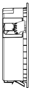
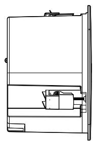
Dimensioni



ELYSION 6CT
In-ceiling Speaker
EN 54-24:2008
Dimensioni


ELYSION 4CT
| 16Ω | 7.5W | 15W | 30W | X | 100V |
| 3.75W | 7.5W | 15W | 30W | 70V |
ELYSION 6CT
| 16Ω | 15W | 30W | 60W | X | 100V |
| 7.5W | 15W | 30W | 60W | 70V |
Avvertenze

Avvertenze

STEP 3.
STEP 4.
SELETTORE DI POTENZA
STEP 6.
SCANSIONARE PER RICEVERE INFORMAZIONI SUL RICICLO
SI PREGA DI SEGUIRE LE DIRETTIVE DELLA PROPRIA ZONA
https://docs.fbt.it/filebrowser/share/l2CuWAX-
PROTEZIONI
Cartone Alveolare
RACCOLTA CARTA


SACCHETTI
QUICK START GUIDE
Keep this document in a safe place so that it is available for future reference. Regularly check the FBT website for the latest version of this document. When reselling this product, hand over this document to the new owner. For informed use of the system, always consult the dedicated guides available on the FBT website on the product pages.
FBT Elettronica SpA - 62019 Recanati (Italy)
www.fbt.it | info@fbt.it


ELYSION
4CT - 6CT
SAFETY PRECAUTIONS....18
Important safety instructions....18
PACKAGE CONTENTS....19
GENERAL FEATURES....20
Introduction....20
ELYSION 4CT....21
ELYSION 6CT....22
CONNECTION 23
Cautions....23
Costant Voltage systems....24
Costant Volate connections....24
INSTALLATION....25
Cautions....25
TECHNICAL SPECIFICATIONS 28
WASTE & DISPOSAL....29
Product specifications....29
Packing specifications....29

WARNING
RISK OF ELECTRIC SHOCK DO NOT OPEN

TO AVOID THE RISK OF ELECTRIC SHOCK, DO NOT OPEN THE PRODUCT, DO NOT USE MECHANICAL TOOLS INSIDE, AND CONTACT A QUALIFIED SERVICE CENTER. THE DEVICE MUST BE CONNECTED TO THE AUDIO SYSTEM IN ACCORDANCE WITH APPLICABLE REGULATIONS.

This product conforms to applicable EU directive requirements.
2026

This product conforms to all applicable UK regulations.
All informations included in this operating manual have been scrupulously controlled; however FBT is not responsible for eventual mistakes. FBT Elettronica SpA has the right to amed products and specifications without notice.
This manual contains important about the correct and safe use of the device. Before connecting and using this product please read this instruction manual carefully and keep it on hand for future reference. The manual is to be considered an integral part of this product and must accompany it when it changes ownership as a reference for correct installation and use as well as for the safety precautions. FBT SpA will not assume any responsibility for the incorrect installation and/or use of this product.
Important safety instructions

- Read, follow, and keep these instructions.
• Pay attention to all warnings. - Clean only with a dry cloth.
- Do not defeat the safety purpose of polarised or grounding-type plugs. Polarized plugs have two blades, with one wider than the other. A grounding-type plug has two blades and a third grounding prong. The wide blade or the third prong is provided for your safety. If the provided plug does not fit into your outlet, consult an electrician for replacement of the obsolete outlet.
- The speaker line (amplifier output) can have a sufficiently high voltage (e.g., 100V) that poses a danger to people; never proceed with the installation or connection of speakers when the line is energized.
- Ensure all connections are correct and that the input voltage (in a constant voltage system) or the speaker impedance is compatible with the amplifier's output characteristics.
- To prevent inductive effects from causing hum, noise and a bad system working, loudspeaker lines should not be laid together with other electric cables (mains), microphone or line level signal cables connected to amplifier inputs.
- Do not attempt to service/modify/repair the product yourself. Contact authorized service centres or qualified personnel.
- When suspended installation is foreseen, use only the appropriate anchor points.
- Also verify the suitability of the support (wall, ceiling, etc.) and the components used for fastening (anchors, screws, etc.).
- For technical assistance, contact qualified personnel. Technical assistance is required if the unit is damaged, such as when there are operating anomalies or if the unit has been dropped.

ELYSION units x2

Cap xl
(optional for installation)

Safety Cable x1

Screws for Cap x4

Screws for Safety Cable x2

Cable Gland x2
(optional for installation)

Quick Start Guide x1
Introduction
ELYSION 4CT is a 4" 2-way speaker with a shallow cabinet for easy installation in most false ceilings. ELYSION 6CT is a 6,5" 2-way speaker that guarantees increased power output. Even if in different material and dimensions, the models share the same concept on the cabinet design: magnetic paintable front grille, springlock mounting clamps safety hook, front power switch. Both models are equipped with line transformer for Hi-Z application and ceramic terminal block with thermal fuse that allows to link other speakers directly onboard. All models are available in black or white front grille standard colors, also allowing for customization to suit any decoration. Whether you are looking to upgrade your home audio system, enhance your office's sound quality, or create an immersive entertainment space, ELYSION's in-ceiling speakers are the perfect solution. Experience high quality sound with deep bass like never before, without compromising on style or integration.
ELYSION 8S is an in-ceiling 8" subwoofer designed to enhance bass performance in different applications. The cabinet hosts a magnetic paintable front grille, a springlock mounting clamp safety hook and a front power switch. ELYSION 8S is equipped with line transformer for Hi-Z applications and ceramic terminal block with thermal fuse that allow to link other speakers directly onboard. The standard front grille can be black or white with the possibility to customize the product in every RAL color.

ELYSION 4CT
In-ceiling Speaker

ELYSION 6CT
In-ceiling Speaker
ELYSION 4CT
In-ceiling Speaker
EN 54-24:2008
• 2-way configuration
• 4" LF woofer with 1" coil
• 0.75" HF driver with 0.75" coil
• Recommended amplifier: 60W / 16 Ohm
• Frequency response from 85Hz to 20kHz
• Transformer taps (@100V): 30/15/7.5W bypass
- ABS cabinet with scratch-resistant paint and magnetic steel front grille
• Springlock mounting clamps installation
• Ceramic terminal block
• EN 54-24 certificate of conformity / TYPE A
- Ideal match with ELYSION 8S subwoofer
• Available in black and white colours

Dimensions


ELYSION 6CT
In-ceiling Speaker
EN 54-24:2008
• 2-way configuration
- 6.5" LF woofer with 1.5" coil
• 0.75" HF driver with 0.75" coil
• Recommended amplifier: 120W / 16 Ohm
• Frequency response from 68Hz to 20kHz
• Transformer taps (@100V): 60/30/15W bypass
- ABS cabinet with scratch-resistant paint and magnetic steel front grille
• Springlock mounting clamps installation
• Ceramic terminal block
• EN 54-24 certificate of conformity / TYPE A
- Ideal match with ELYSION 8S subwoofer
• Available in black and white colours

Dimensions



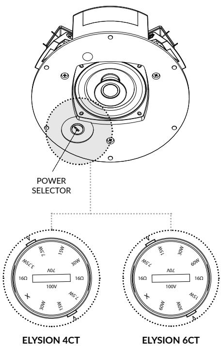
ELYSION 4CT
| 16Ω | 7.5W | 15W | 30W | X | 100V |
| 3.75W | 7.5W | 15W | 30W | 70V |
ELYSION 6CT
| 16Ω | 15W | 30W | 60W | X | 100V |
| 7.5W | 15W | 30W | 60W | 70V |
Cautions

- It is recommended to have qualified personnel handle the speaker connections.
- Do not connect the speaker while the amplifier is on to prevent the risk of electric shock.
- Thoroughly check all connections before powering on the system to ensure no short circuits.
- The system should be installed following all current electrical installation regulations.
- Use cables with conductors of the appropriate gauge, considering their length and the speaker's power.
- Keep audio cables separate from all other signal or power cables to prevent hums or interference that might lead to system malfunctions.
⚠ WARNING | DO NOT CONNECT LOW IMPEDANCE SPEAKER INPUTS (e.g. 8Ω) TO A CONSTANT VOLTAGE 100V LINE.
⚠ WARNING | Connect the cable for the emergency system to a junction box that contains a ceramic terminal and a thermal fuse, in accordance with fire safety regulations.
⚠ WARNING | For speaker connections, only two conductors are used. It is essential to isolate and protect the other two unused conductors to prevent system malfunction.
Constant voltage system
The ELYSION model is equipped with a “Multi-terminal” ceramic block located on the back of the speaker.
This connection system requires that each speaker be equipped with a dedicated line transformer. The amplifier must have steady voltage outputs of 100V or 70V. Should it be necessary, the loudspeakers connected in parallel to the output of the amplifier allow you to extend the installation from any of the previously installed speakers, and also to remove the loudspeakers when no longer needed. When making the connections, you have to observe the “phase” of speaker connection to its own transformer and also that of the parallel connection of the speakers. The input voltage of the speaker must match the output voltage of the amplifier; the total rating power of all speakers connected to the line must not be greater than that of the amplifier.

Constant voltage connections
- Connect the NEGATIVE (com) conductor of the speaker to the 100V line connected to the amplifier terminal marked "0" / "com."
- Connect the POSITIVE (+) conductor to the terminal block terminal most appropriate for the desired power level.

Cautions

The installation of ELYSION in-ceiling speakers and the specific mounting instructions must be executed exclusively by qualified personnel, in full compliance with the rules and safety standards in force in the country where the installation takes place.
- Each ceiling element or other structure where ELYSION is installed must be capable of safely supporting the load.
- To prevent damage to people or property, the system must be equipped with a safety cable and safety screws.
- When selecting the installation location or mounting supports, ensure that all components can bear the weight of the loudspeaker with an appropriate safety factor.
- The use of non-original mounting supports may result in hazardous instability, potentially causing injury or damage.
- ELYSION loudspeakers must be installed only using the original accessories (spring clamps).
- For fixed installations, regular and specific inspections must always be planned and carried out to verify all components responsible for ensuring the long-term safety of the system.
NOTE | The cover and cable glands are OPTIONAL for installation.
WARNING | RISK OF DAMAGE!
Avoid over-tightening, forcing, or over-loosening screws during installation when using a power drill or electric screwdriver.
WARNING | FBT ELETTRONICA SpA is not responsible for any damage to people or property in the event of non-compliance with these instructions or failure to verify the safety factor of all elements involved in the system's installation.

STEP 1.
Insert the ELYSION speaker into the structure/ceiling. For a movable ceiling, push inside the three springlock mounting clamps.

STEP 2.
Insert the entire ELYSION into the structure/ceiling. Allow the spring clamps to snap into place to prevent the speaker from falling.

STEP 3.
Remove the magnetic grille from the speaker.

STEP 4.
Use the three adjusting screws to compensate for the thickness between the false ceiling and the ELYSION, securing the speaker to the structure.

WARNING | RISK OF DAMAGE!
Do not overtighten or apply excessive force to the screws!

STEP 5.
Select the desired power setting using the appropriate selector.

POWER SELECTOR
STEP 6.
Reattach the steel magnetic grille to the ELYSION in-celing speaker.

| GENERAL | ELYSION 4CT | ELYSION 6CT | |
| Code | Black | 47330 | 47328 |
| White | 47331 | 47329 | |
| Configuration | way | 2 | 2 |
| Low frequency woofer | inch | 4 - 1 coil | 6.5 - 1.5 coil |
| High frequency driver | inch | 0.75 - 0.75 coil | 0.75 - 0.75 coil |
| Operating Storage temperature | °C | -25 ÷ +55 -40 ÷ +70 | -25 ÷ +55 / -40 ÷ +70 |
| Relative humidity | <95% | <95% | |
ACOUSTIC SPECIFICATIONS
| Frequency response (@-6dB) | Hz | 85 - 20k | 68 - 20k |
| Sensitivity (4m/1m) | dB | 86 / 74 | 89.5 |
| MAX SPL (4m/1m) | dB | 88 / 100 | 94.5 / 106.5 |
| Dispersion (@-6dB) Horizontal = Vertical | 175° (500Hz) | 178° (500Hz) | |
| 158° (1kHz) | 148° (1kHz) | ||
| 149° (2kHz) | 73° (2kHz) | ||
| 51° (4kHz) | 105° (4kHz) | ||
| 97° (8kHz) | 70° (8kHz) | ||
| Recommended HP filter | Hz-24 oct. | 75 - 24 | 60 - 24 |
INPUT & OUTPUT
| Input connectors | Ceramic terminal block | Ceramic terminal block |
AMPLIFIER
| Recommended amplifier | W RMS | 60 | 120 |
| Rated noise power 100hrs | W (V RMS) | 30 (21.9) | 60 (31) |
| Nominal impedance | Ohm | 16 | 16 |
| Nominal impedance 100V line | Ohm (W) | 1333 (7.5) | 666 (15) |
| 666 (15) | 333 (30) | ||
| 333 (30) | 166 (60) | ||
| Nominal impedance 70V line | Ohm (W) | 166 (30) | 83 (60) |
MECHANICAL SPECIFICATIONS
| Material | Cabinet | ABS | ABS |
| Grille | Steel | Steel | |
| Net dimensions (WxHxD) | mm | 325 × 101 | 325 × 201 |
| inch | 12.79 × 3.97 | 12.79 × 7.91 | |
| Net weight | kg | 3.50 | 4.50 |
| lb | 7.71 | 9.92 |
Product specifications

Where affixed on the equipment or package, the barred waste bin sign indicates that the product must be separated from other waste at the end of its working life for disposal. At the end of use, the user must deliver the product to a suitable recycling centre or return it to the dealer when purchasing a new product.

Adequate disposal of the decommissioned equipment for recycling, treatment and environmentally compatible disposal contributes in preventing potentially negative effects on the environment and health and promotes the reuse and/or recycling of equipment materials. Abusive product disposal by the user is punishable by law with administrative sanctions.

Check the instructions of your municipality. Separate the components and disposal them properly.
AVOID RELEASE TO THE ENVIROMENT

SCAN FOR RECYCLING INFO
PLEASE FOLLOW YOUR AREA DISPOSITION
https://docs.fbt.it/filebrowser/share/l2CuWAX-
Packing specifications

BOX
Corrugated Cardboard
PAPER DISPOSAL

PROTECTIONS
Corrugated Cardboard
PAPER DISPOSAL


PROTECTIONS
Honeycomb Cardboard
PAPER DISPOSAL


BAGS
Low-density Polyethylene
PLASTIC DISPOSAL


QUICK START GUIDE
Paper
PAPER DISPOSAL


FBT
FBT ELETTRONICA SPA
Via Paolo Soprani 1 - 62019 RECANATI - Italy
Tel. 071750591 - info@fbt.it - www.fbt.it



- ELYSION 4CT
- IN-CEILING SPEAKER
- DIMENSIONI
- ELYSION 6CT
- AVVERTENZE
- STEP
- ELYSION
- SAFETY PRECAUTIONS
- PACKAGE CONTENTS
- GENERAL FEATURES
- CONNECTION
- INSTALLATION
- TECHNICAL SPECIFICATIONS
- WASTE & DISPOSAL
- WARNING
- IMPORTANT SAFETY INSTRUCTIONS
- INTRODUCTION
- DIMENSIONS
- CAUTIONS
- CONSTANT VOLTAGE SYSTEM
- CONSTANT VOLTAGE CONNECTIONS
- PRODUCT SPECIFICATIONS
- AVOID RELEASE TO THE ENVIROMENT
- SCAN FOR RECYCLING INFO
- PACKING SPECIFICATIONS
- BOX
- PROTECTIONS
- BAGS
- QUICK START GUIDE
- FBT ELETTRONICA SPA
Brand : FBT
Model : ELYSION 4CT - 6CT
Category : In-wall speaker