
CSU4000 / CST4000 - FBT - Free user manual and instructions
Find the device manual for free CSU4000 / CST4000 FBT in PDF.


User questions about CSU4000 / CST4000 FBT
0 question about this device. Answer the ones you know or ask your own.
Ask a new question about this device
Download the instructions for your in PDF format for free! Find your manual CSU4000 / CST4000 - FBT and take your electronic device back in hand. On this page are published all the documents necessary for the use of your device. CSU4000 / CST4000 by FBT.
USER MANUAL CSU4000 / CST4000 FBT
WITH REMOSET® 2.4 RF SYNCHRONIZING TECHNOLOGY

ITA / MANUALE D'USO ENG / OPERATING MANUAL
CSU4000 / CST4000
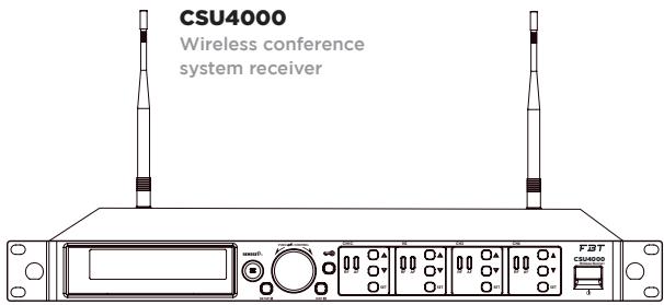
UHF PLL 4-channel wireless conference system receiver // CSU4000
UHF PLL wireless conference system transmitter // CST4000
UHF PLL 4-channel wireless conference system receiver // CSU4000


ANTENNA
*2

WIND SHIELD
*4

Cavo
CORRENTE ALTERNATA
*1

Cavo a cascata
RF
*2

XLR (M) / XLR(F)
Cavo Audio
*1

Cavo a cascata
CORRENTE
ALTERNATA
*1

| COLLEGAMENTO DEL RICEVITORE
| REGOLATORE LOGICO E USCITA IN TENSIONE

| INSTALLAZIONE DISPOSITIVO // CST4000
| 1. All Groups |
| 2. Result List |
| 3. Current Group |
| 4. Return |

Squelch
□ Frequency
□ Sensitivity
□ Attenuate (Only for BPT)
□ Low Cut
□ RF power
□ AutoOFF
□ KeyLock
□ Save and exit
□ Exit without saving


Indicatore
Altro
Notes for system operations 4
Features 4
Disposal 4
SPECIFICATIONS CSU4000 5
SPECIFICATIONS CST4000 6
CONTROL & FUCTIONS 7
Front panel 7
Rear panel 8
LCD Displays 9
Setting page 9
CST4000 10
ACCESSORIES 11
CONNECTION 12
Connecting the receiver 12
Logic controller & voltage output 13
Installing transmitter // CST4000 13
Self-defined groups 15
Priority setting 15
Define receiver channel 16
Receiver channel 1 16
PAIRING FOR REMOSET 19
Notes for the product 23
Important note 23
| GENERAL INFORMATIONS

CSU4000 / CST4000 Manual
Versione: 1.1 ita, en | 06/2023
MADE IN TAIWAN
Keep this document in a safe palce so that it is available for future reference. We recommend you to regularly check the FBT website for the latest version of this document. When reselling this product hand over this document to the new owner. To use the system properly, always consult the specific guides available on the product pages of the FBT website.
FBT Elettronica SpA - 62019 Recanati (Italy)
www.fbt.it | info@fbt.it
- Before connecting to power, make sure the voltage marked on equipment is the same as that on the power socket.
- Do not place the machine at a place where high temperature and humidity are expected.
- Do not operate the system with wet hands.
- Keep the machine away from any heat or ignition source.
- Before setting up the machine, make sure that the volume is set at the minimum for both the mixer and amplifier.
- Caution: The suitable environment for this product is with a temperature between -10°C (14°F) and +50°C (122°F).
| FEATURES
- CSU4000 is designed with FBT newest wireless and conferencing technology. It provides maximized compatible channels with a given bandwidth. Built in logic circuit provides conferencing feature. A microphone assigned with priority will work as a chairman unit. It overrides other microphones. Logic setting of one CSU4000 receivers can be cascaded. A microphone with priority in one receiver will also have priority in a cascaded system. The patented REMOSET® synchronizes all four microphones simultaneously by push one button.
- The microphone is of 108 MHz bandwidth(MAX). This feature allows more attendants to join the conference.
- Antenna outputs and AC power supply are designed to be cascaded.
| DISPOSAL i

Where affixed on the equipment or package, the barred waste bin sign indicates that the product must be separated from other waste at the end of its working life for disposal. At the end of use, the user must deliver the product to a suitable recycling centre or return it to the dealer when purchasing a new product. Adequate disposal of the decommissioned equipment for recycling, treatment and environmentally compatible disposal contributes in preventing potentially negati-
ve effects on the environment and health and promotes the reuse and/or recycling of equipment materials. Abusive product disposal by the user is punishable by law with administrative sanctions.
UHF PLL 4-channel wireless conference system receiver // CSU4000
| Frequency oscillation | PLL Synthesized Control |
| Carrier frequency | 470~960 MHz |
| No. of channels | 4 channels |
| Channel pairing | RF 2.4G REMOSET |
| Diversity | Antenna diversity |
| Bandwidth | 36MHz |
| Signal/noise ratio | >105dB(A) |
| Total harmonic distortion | <0.6%@1KHz |
| Sensitivity | -95dBm · S/N>80dB |
| Audio frequency response | 60Hz~16KHz±2dB |
| Antenna connector | BNC female |
| Antenna booster power | DC12V/100mA |
| Display | LCD+LED |
| Controls | Power On/Off, Groups, Channels, Frequency, Sensitivity, Key Lock, Volume, Output Attenuation (Xlr), Frequency Scan (On/Off), Antenna Power, Display Setting, Priority Setting, Remoset Id Number, Remoset Setting. |
| Audio output level (MAX) | ∅6.3 Phone Jack : +4dBu |
| XLR Jack : +10dBu(Line) · -10dBu(MIC) | |
| Audio output impedance | 600Ω |
| Mute | Noise mute and Pilot Tone |
| Output port | 5 balance XLR ports, 1 unbalance ∅6.3mm jack |
| Logic Controller & Voltage Output | +5Vdc |
| Automix Control Socket | In/out (8 pin mini DIN connector) |
| Power | AC 100~240 VAC |
| Dimensions (DxWxH) mm | 485 x 260 x 45 |
| Weight | 2.4 kg |
| Note | Actual Product specifications may vary depending on model and region |
UHF PLL wireless conference system transmitter // CST4000
| Frequency oscillation | PLL Synthesized Control |
| Carrier frequency | 470~960 MHz |
| Bandwidth 108MHz (MAX) | 108MHz (MAX) |
| Paring | RF 2.4G REMOSET® |
| RF power output | Low / High |
| RF stability | <±10KHz@Fc |
| Frequency deviation | ±48KHz |
| Spurious Emissions | <-50dBc |
| Display | LCD |
| Controls | Power ON/OFF, Talk, groups, channels, frequency, sensitivity adjustment, Remoset ID pairing, RF output, key lock, Low cut, Sync |
| Battery | UM3, AA x 2 |
| Charging | Yes |
| Dimension (DxWxH) mm | 138 x 116 x 29 |
| Weight | 0.76 kg |
| Note | Actual Product specifications may vary depending on model and region |

FRONT PANEL

UHF PLL 4-channel wireless conference system receiver // CSU4000
- Power ON/OFF: ON: Push once to turn on OFF: Push and hold until "Power OFF" is shown on the LCD to turn off.
- EXIT: Push exit to cancel a selection or exit from the current menu when CSU4000 is in the "setting menu."
- Rotary Switch: When in the "function menu," turn the switch to select the desired function; push the switch (or SETUP) to enter the selection and spin the switch to select the setting. Push [SETUP] to save the setting.
-
SETUP: Push and hold for 2 seconds to enter the vsetting menu." Push [SETUP] to save the setting once the selection and setting are made according to "3. Rotary Switch."
-
REMOSET: When the receiver setting is done, push REMOSET® to transmit the setting data to the handheld or body-pack transmitter.
- LCD display: See "Receiver LCD display instructions."
- AF: Indicates the current strength of audio frequency signals.
- RF: Indicates the current strength of radio frequency signals.
- Key lock: Push and hold for 2 seconds to lock all keys, and again to unlock.
- Volume keys: Push Δ / keys to adjust the volume between 0 and -31dB.
| REAR PANEL

- Selection key: Push this button a. Push SETUP to enter the setting for the selected channel for parameter settings. b. Push REMOSET to transmit the setting data to the transmitter in this selected channel.
- Logic Controller Output: An external logic trigger device, such as a camera-like trigger device, can be connected.
- ∅6.3 audio output jack: unbalanced audio signal output after mixing
- XLR audio jack: balanced audio signal output; XLR audio jack: balanced audio signal output after mixing
-
Antenna A (B) input terminal: BNC antenna input jack that also provides DC12V/100mA output.
-
LINK IN: Priority Control Signal and Mixed Signal Input Port; LINK OUT: Priority Control Signal and Mixed Signal Output Port
- AC input: 100\~240 VAC Note: Each cacading may bring 1.2dB attenuation to RF signal.
- AC input cascaded: use AC double power cable (optional) for power cascading.
- RF signal A (B) output terminal: RF signal output jack; it is possible to connect the RF A (or B) OUT of the first unit to the antenna A (or B) IN of the second unit with a BNC-BNC signal cable, and then the RF A (or B) OUT of the second unit to the antenna A (or B) IN of the third unit, and so on and so forth. The cascade may consist of up to 10 units to minimize the number of antennas used.
| LCD DISPLAYS
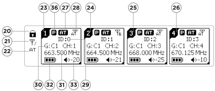
| SETTING PAGE

- Key lock
- Antenna power supply ON
- Mixed output attenuation ON
- Receiver channel 1
- Receiver channel 2
- Receiver channel 3
- Receiver channel 4
- Output attenuation ON
- Antenna selection A/B
- Device ID
- Group/channel
-
Frequency
-
Transmitter battery
3blocks: CS-W4T microphone is used


:waiting for battery information
from transmitter
- Volume
- Transmitter battery
3blocks: CS-W4T microphone is used


:waiting for battery information
from transmitter

:no microphone signal
- Setting window
- Priority Indication

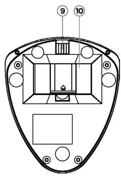

UHF PLL handheld transmitter // CST4000
- Power Switch/LOCK: The first segment is to turn ON the machine, the second segment is to LOCK the machine, which can lock the buttons (excluding the call button).
- Gooseneck tube connection socket: Gooseneck tubes of different lengths can be used.
- LED status indicator: Status indication. Including: electric quantity and frequency indication.
- LCD screen: Displays the content parameters to be set up for the transmitter.
- LED status indicator for a call: When in the callable state, a red light is displayed.
-
SET button: Set the content parameters. Including: frequency, group, channel, sensitivity, transmit power, bass attenuation, ID code, frequency function (ON/OFF), digital audio code.
-
Up/Down Selection Keys: The "SET key" can also be used to change the parameter settings.
- Call Button: Press the button, the indicator light will be on, and you can make a call. Then, press the indicator light to end the call.
- Charging contact module: if rechargeable batteries are used, charging is possible with the matching charger.
- Battery compartment: it holds 2 UM3, AA 1.5V Alkaline batteries or MiNH rechargeable batteries.
| LCD DISPLAYS
- Indication of frequency, group and channel
- Battery level
- Frequency (MHz)
D8P-1
Extension Cable
*1

ANTENNA
*2

WIND SHIELD
*4

AC POWER
Cable
*1

CASCADING RF
Cable
*2

XLR (M) / XLR(F)
Audio Cable
*1

AC POWER
Cascading Cable
*1

| CONNECTING THE RECEIVER
1. Connect the audio signal cable
Connect the CSU4000 audio output to a mixer or an amplifier: Audio cable: one end of the XLR or ∅6.3mm audio cable is connected to the "AF output balanced" of CSU4000 and the other to the audio input of the mixer or amplifier.
2. Connect the power
Connect AC power cable: insert one end to the receiver's AC jack and the other to AC power outlet (100\~240VAC).

Cascading of AC power cable and antennas
*Up to 10 units can be cascaded for power/antenna.

When the microphone channel is turned on, the control signal corresponding to this channel will continue to output “High” (+5Vdc). When turned off, the control signal output of this channel will be “Low” (0V). The logic control signals can be used to trigger other applications, such as: the video camera.


INSTALLING TRANSMITTER // CST4000
- Open the battery cover (picture1)
- Place 2 AA batteries in the battery compartment according to their polarity.
- Cap the battery cover.
- Boot Mode (picture2)
a. The first segment turns the power slide switch from off to on to turn on the power.
b. The second segment turns the power slide switch from on to lock, so as to avoid accidental trigger by users. - Define the transmitter parameters according to the instructions.
- Press the Call button to make a call. (picture 3)

| PARAMETER SETTING
Push and hold "SET" for 2 seconds to enter the setting mode. Turn the rotary switch to select the desired item. Push the rotary switch (or SETUP) to enter the setting page. Spin the switch to select the desired value or function. Push [SETUP] to save the settings. Push [EXIT] to return to the previous page.
| SYSTEM SETTING

Display
| Contrast | 0~9 (default: 5) |
| Brightness | 0~9 (default: 5) |

Indictor
| Brightness | 0~9 (default: 5) |

Antenna power supply
| ON | (DC12V/100mA is provided to) power the external antenna booster. |
| OFF |

Mixed output level
| OFF (Line) | Line output is selected for balanced mixing output level. |
| On (Mic) | Mic output is selected for balanced mixing output level. |

Reset to factory defaults
Push and hold SETUP for 2 seconds and the system is reset to factory defaults and restarts.

Return
Return: push SETUP to return to the previous page.


| SELF-DEFINED GROUPS

Edit a self-defined group
| G | U1~U6 (group no.) |
| CH | 1~24 (channel) |
----MHz (frequency setting)

Delete a self-defined group
| Group | Select the group to be deleted from U1~U6, push SETUP and the program will ask if you want to delete the group. Push “Yes” to delete. |

Return
Return: push SETUP to return to the previous page.
| PRIORITY SETTING

Calling Mode
| Priority | Turn on the Call Priority function. |
| Open Mode | Unrestricted Speech: 4 receivers can speak at the same time, and they are not subject to the trigger threshold. |

Trigger Thresholds
-50dB\~-30dB: The threshold volume to the trigger priority function can be set. The larger the setting value, the better the sound plug can avoid receiving unnecessary noise and activating the priority function by mistake.

Receiver 1\~4 Priority Setting
| Priority | The receiver with the priority function has the highest right to make a call. When the priority is making a call, those without priority will be forced to reduce their volumes (attenuated by 30dB approximately). |
| No Priority | When there is no priority, the right to call is given to the one who gives a call first. |

| Bypass | Yes |
| Threshold | -30 dB |
| Rx1 Priority | No |
| Rx2 Priority | Yes |
| Bypass | Yes |
| Threshold | -30 dB |
| Rx1 Priority | Open |
| Rx2 Priority | Open |
| Bypass | Yes |
| Threshold | -30 dB |
| Rx1 Priority | No |
| Rx2 Priority | Yes |
| Rx3 Priority | No |
| Rx4 Priority | No |
| Delay Time | 1 Sec |
| Return |
| Rx3 Priority | No |
| Rx4 Priority | No |
| Delay Time | 1 Sec |
| Return |

Delay Time
0.5\~5 second: Set the delay time for the system to release the call after the end of the call.

Return
Return: push SETUP to return to the previous page.
DEFINE RECEIVER CHANNEL
- Push and hold [SETUP] for 2 seconds. Spin the rotary switch to select the desired receiver channel in the main menu. Push the switch to start defining.
or
- Push [SEL] of the receiver channel to be defined. Push and hold [SETUP] for 2 seconds to start defining.
| RECEIVER CHANNEL 1

Frequency setting
Select the left 3 digits of the frequency; spin the rotary switch to adjust in the increment of “+/-” 1 MHz. Push the switch to confirm the selection. Select the right 3 digits of the frequency; spin the rotary switch to adjust in the increment of “+/-” 0.025 MHz. Push [SETUP] to confirm and save the selection.

Default group
Spin the rotary switch to select group "G:" through 1 to 6. Push the switch to confirm the selection. Spin the rotary switch again to select channel "CH:" up to 22 channels are available. Push [SETUP] to confirm and save the selection.

Channel scan
| Scan all groups | Push the rotary switch to start scanning. The system goes to the selection page once the scanning is done. It is also possible to arrive at here through menu. |
| Scan result | Push the rotary switch to enter the selection page and examine the result. Select an available channel and push [SETUP] to save the selection. |
| Scan current group | The next group will be scanned every time the rotary switch is pushed. Make the selection and push [SETUP] to save it. |
| Rx3 Priority | No |
| Rx4 Priority | No |
| Delay Time | 1 Sec |
| Return |
| Rx3 Priority | No |
| Rx4 Priority | No |
| Delay Time | 1 Sec |
| Return |
| 3. CH1 |
| 4. CH2 |
| 5. CH3 |
| 6. CH4 |
| 1 | ID:1 | LINE | AP |
| G:1 | CH:1 | ||
| -30 | 663.500 MHz | ||
| Setup | ® Remoset | ||
| Setup Frequency |
| 663.500 MHz |
| G: 1 CH:1 |
| Setup Group | |
| G: 1 | CH: 1 |
| 663.500 MHz | |
| 1. All Groups |
| 2. Result List |
| 3. Current Group |
| 4. Return |

Squelch
+10\~ -5: the higher the value, the less sensitive the receiving, and vice versa. The default is 0.

Device ID
Device ID: 0\~255: this setting affects the use of REMOSET; both the receiver and transmitter must be on the same Device ID before REMOSET is available. Note | This does not apply when the microphone Device ID is not activated.

Output level
| Line | Line output is selected for channel 1 balanced output level. |
| Mic | Mic output is selected for channel 1 balanced output level. |

Microphone options
1. Sensitivity
Adjustment range: -15db\~+15db: the default is 0.
2. Input attenuation
| ON | Audio input attenuation by 20dB (depending on whether the transmitter has the corresponding function) |
| OFF | No attenuation (default) |
3. Low Cut
| ON | Cut off rate at 150Hz (depending on whether the transmitter has the corresponding function) |
| OFF | No attenuation (default) |
4. RF power
| HI | High transmission power 50mW |
| LO (default) | Low transmission power 10mW |
5. AUTO-OFF
The Microphone's Automatic Shutdown Time (in the MUTED state)
| OFF | Turn off this function. |
| 1 | Automatic shutdown after 1 min. |
| 10 | Automatic shutdown after 10 min. |
| 30 | Automatic shutdown after 30 min. |
Note | The Default Value is set to 10 minutes.


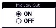


- Key lock
| Lock ON | Microphone is in the Lock ON mode as pairing is complete |
| Lock OFF | Microphone is not locked as pairing is complete (default) |
Mic KeyLock
ON
○ OFF
7. Remoset options
Use the rotary switch to search the items for REMO-SET and push the knob to select.
□ Frequency
□ Sensitivity
□ Attenuate (Only for BPT)
□ Low Cut
□ RF power
□ AutoOFF
□ KeyLock
□ Save and exit
□ Exit without saving
Frequency
Sensitivity
Attenuate
Low Cut
RF Power
AutoOFF
KeyLock
□ Save and Exit
□ Exit Without Save
Push [SETUP] to save the selection, or just select "Save and Exit."
*At least one of the above has to be selected.
8. Return
Return: push [SETUP] to return to the previous page.
| RECEIVER CHANNEL 2
See channel 1
| RECEIVER CHANNEL 3
See channel 1
| RECEIVER CHANNEL 4
See channel 1
Exit setting
Push [SETUP] to exit the setting page and return to the main page.
Volume adjustment
Push Δ / key at each channel to adjust the volume up or down.
Mute, -31dB \~ 0dB. The default is -10 dB.
- REMOSET: Push [REMOSET] and the blue indicator will start flashing, indicating that the frequency data is being transmitted.
- REMOSET successful: The blue indicator lights up on the transmitter for 3 seconds and that on the receiver stops flashing.
- REMOSET failed: If the blue indicator flashes slowly on the receiver, check that :
(1) The "frequency range labels" on "both" the receiver and transmitter are the same;
(2)"Pairing" in the function menu of the transmitter is "activated;"
(3) The "Device ID" on the transmitter is the same as that on the receiver; and
(4) Transmitter battery is low (synchronization is impossible when battery is low).
*It should be avoided to have two or more receivers on REMOSET when REMOSET is used, as sometimes it prevents pairing due to the mutual interference of REMOSET signals.


- Pairing 4 microphones simultaneously: Push [REMOSET] and the blue indicator starts to flashing. On the display all 4 receiver channels show "Synchronizing," indicating that data are being transmitted to all 4 microphones.

CSU4000
- Pairing a single microphone: Push [SEL] of the receiver channel to be paired. Push [REMOSET] and the blue indicator starts to flash. On the display the receiver channel is “Synchronizing,” indicating that data is being transmitted to that microphone.

Others
Push "SEL" below each of the channel volume keys:
Push [SETUP] to enter the page containing the selections of that channel for parameter settings.
Push [REMOSET] to start pairing that channel; other channels remains standing by.
| PARAMETER SETTING
Push and hold [SET] for 2 seconds to enter the setting mode. Push [SET] repeatedly to locate the desired item. Use Δ / for parameter settings. Push [SET] again to save the changes and exit.
| SYSTEM SETTING

FREQ: frequency setting
| Increment of 1MHz | Select with Δ / |
| Increment of 0.025MHz | Select with Δ / |

GROUP: group/channel setting
| G (group) | Select default group 1~6 |
| CH (channel) | Select default channel(s), up to 22 |

Sensitivity: For microphone input
| Normal sensitivity | GAIN: +15dB |
| GAIN: +12dB | |
| GAIN: +9dB | |
| GAIN: +6dB | |
| GAIN: +3dB | |
| GAIN: 0dB | |
| GAIN: -3dB | |
| GAIN: -6dB | |
| GAIN: -9dB | |
| GAIN: -12dB | |
| GAIN: -15dB |

RFP: RF power of microphone
| rF Lo | Low (default) |
| rF Hi | High |

Start with those digits in 1MHz and then those in 0.025MHz

Start with group number and then channel number.

The sensitivity is at GAIN -6dB (default) as shown above.

RFP Hi
RFP low

Low Cut
| Lc OFF | OFF |
| Lc ON | ON (150Hz) |

Device ID
| ID OFF | Device ID deactivated |
| ID 0~255 | Device ID 0 ~ 255 |

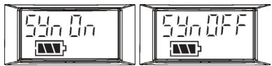
Remoset (ON / OFF)
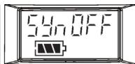
| Syn ON | Remoset activated |
| Syn OFF | Remoset deactivated |


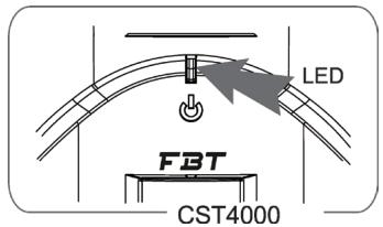
Indicator
Green: power is sufficient, > 2V
Red: power low, ≤ 2V
Blue: on for 3 seconds, indicates pairing successfully
Blue flashing: data receiving error
Others
Battery charging is supported. The transmitter turns off automatically when charging. When battery is < 1.8V, the transmitter will turn off automatically. If the microphone is turned off with the mute switch on mute, just slide the switch up to turn the microphone on.
| ALERT FUCTION
The alert screen will blink slowly under these circumstance:
- When microphone is under mute mode.
- When microphone's power is OFF.
- When microphone's battery level is too low.


NOTES FOR THE PRODUCT

- For the optimized reception, keep the receiver 3m or more away from the transmitter.
- Receivers and transmitters shall be kept at least 50cm away from any metal object.
- Do not point the receiver directly into a speaker or there will be annoying feedback noises.
- It is recommended to hold the transmitter (microphone) at the middle section for the optimized audio pickup.
- In case that the microphone is not used for an extended period of time, it is recommended to remove the batteries from the battery bay in order to prevent electrolyte leaks from damaging the transmitter.
- When changing the batteries, it is recommended to change both batteries of the same manufacturer for the optimized power performance.
IMPORTANT NOTE

- The changes or modifications not expressly approved by the party responsible for compliance could void the user's authority to operate the equipment.
- To comply with the FCC RF exposure compliance requirements, no change to the antenna or the device is permitted. Any change to the antenna or the device could result in the device exceeding the RF exposure requirements and void user's authority to operate the device.
- This device complies with Part 15 of the FCC Rules. Operation is subject to the following two conditions: (1) this device may not cause harmful interference, and (2) this device must accept any interference received, including interference that may cause undesired operation.

FBT
FBT ELETTRONICA SPA
Via Paolo Soprani 1 - 62019 RECANATI - Italy
Tel. 071750591 - Fax. 071 7505920
email: info@fbt.it - www.fbt.it
All informations included in this operating manual have been scrupulously controlled; however FBT is not responsible for eventual mistakes. FBT Elettronica SpA has the right to amed products and specifications without notice.
- CSU4000 / CST
- COLLEGAMENTO DEL RICEVITORE
- REGOLATORE LOGICO E USCITA IN TENSIONE
- INSTALLAZIONE DISPOSITIVO // CST
- SQUELCH
- INDICATORE
- ALTRO
- SPECIFICATIONS CSU
- SPECIFICATIONS CST
- CONTROL & FUCTIONS
- CST
- ACCESSORIES
- CONNECTION
- PAIRING FOR REMOSET
- GENERAL INFORMATIONS
- MADE IN TAIWAN
- FEATURES
- DISPOSAL I
- FRONT PANEL
- REAR PANEL
- LCD DISPLAYS
- D8P
- ANTENNA
- WIND SHIELD
- AC POWER
- CASCADING RF
- XLR (M) / XLR(F)
- CONNECTING THE RECEIVER
- CONNECT THE AUDIO SIGNAL CABLE
- CONNECT THE POWER
- CASCADING OF AC POWER CABLE AND ANTENNAS
- INSTALLING TRANSMITTER // CST
- PARAMETER SETTING
- SYSTEM SETTING
- RESET TO FACTORY DEFAULTS
- RETURN
- SELF-DEFINED GROUPS
- PRIORITY SETTING
- TRIGGER THRESHOLDS
- DELAY TIME
- DEFINE RECEIVER CHANNEL
- RECEIVER CHANNEL
- FREQUENCY SETTING
- DEFAULT GROUP
- CHANNEL SCAN
- DEVICE ID
- OUTPUT LEVEL
- MICROPHONE OPTIONS
- SENSITIVITY
- INPUT ATTENUATION
- LOW CUT
- RF POWER
- AUTO-OFF
- MIC KEYLOCK
- REMOSET OPTIONS
- EXIT SETTING
- VOLUME ADJUSTMENT
- OTHERS
- REMOSET (ON / OFF)
- INDICATOR
- ALERT FUCTION
- NOTES FOR THE PRODUCT
- IMPORTANT NOTE
- FBT ELETTRONICA SPA
Brand : FBT
Model : CSU4000 / CST4000