
Digitone - Electronic musical instrument Elektron - Free user manual and instructions
Find the device manual for free Digitone Elektron in PDF.


User questions about Digitone Elektron
0 question about this device. Answer the ones you know or ask your own.
Ask a new question about this device
Download the instructions for your Electronic musical instrument in PDF format for free! Find your manual Digitone - Elektron and take your electronic device back in hand. On this page are published all the documents necessary for the use of your device. Digitone by Elektron.
USER MANUAL Digitone Elektron
Digitone
User Manual
FCC compliance statement
This device complies with part 15 of the FCC rules. Operation is subject to the following two conditions: (1) This device may not cause harmful interference, and (2) this device must accept any interference received, including interference that may cause undesired operation.
NOTE: This equipment has been tested and found to comply with the limits for a Class B digital device, pursuant to Part 15 of the FCC Rules. These limits are designed to provide reasonable protection against harmful interference in a residential installation. This equipment generates, uses and can radiate radio frequency energy and, if not installed and used in accordance with the instructions, may cause harmful interference to radio communications. However, there is no guarantee that interference will not occur in a particular installation. If this equipment does cause harmful interference to radio or television reception, which can be determined by turning the equipment off and on, the user is encouraged to try to correct the interference by one or more of the following measures:
- Reorient or relocate the receiving antenna.
- Increase the separation between the equipment and receiver.
- Connect the equipment into an outlet on a circuit different from that to which the receiver is connected.
- Consult the dealer or an experienced radio/TV technician for help.

WARNING: Cancer and Reproductive Harm – www.P65Warnings.ca.gov
Canada
This Class B digital apparatus complies with Canadian ICES-003.
Cet appareil numérique de la classe B est conforme à la norme NMB-003.
European Union regulation compliance statement
This product has been tested to comply with the Low Voltage Directive 2014/35/EU and the Electromagnetic Compatibility Directive 2014/30/EU. The product meets the requirements of RoHS 2 Directive 2011/65/EU.

This symbol indicates that your product must be disposed of properly according to local laws and regulations.
Legal disclaimer
The information in this document is subject to change without notice and should not be construed as a commitment by Elektron. Elektron assumes no responsibility for any errors that may appear in this document. Elektron may also make improvements and/or changes in the products and programs described in this document at any time without notice. In no event shall Elektron be liable for any special, indirect, or consequential damages or any damages whatsoever resulting from loss of use, data, or profits, whether in an action of contract, negligence, or other action, arising out of or in connection with the use or performance of this information.
IMPORTANT SAFETY AND MAINTENANCE INSTRUCTIONS
Please read these instructions carefully and adhere to the operating advice.
- Do not use this unit near water.
- Never use aggressive cleaners on the casing or on the screen. Remove dust, dirt and fingerprints with a soft, dry and non-abrasive cloth. More persistent dirt can be removed with a slightly damp cloth using only water. Disconnect all cables while doing this. Only reconnect them when the product is safely dry.
- Install in accordance with the manufacturer's instructions. Make sure you place the unit on a stable surface before use. If you mount the unit in a rack, be sure to tighten all four screws in the rack mount holes.
- Connect the unit to an easily accessible electrical outlet close to the unit.
- When transporting the unit, use accessories recommended by the manufacturer or the original box and padding.
-
Do not install near any heat sources such as radiators, heat registers, stoves, or any other equipment (including amplifiers) producing heat.
-
Do not put the PL-2S Protective Cover (Elektron accessory) on the unit while the unit is powered on.
-
This product, by itself or in combination with amplifiers, headphones or speakers, is capable of producing sound levels that may cause permanent hearing loss. Do not operate at a high volume level or at a level that is uncomfortable.
-
Protect the power cord from being walked on or pinched particularly at plugs, convenience receptacles, and the point where they exit from the unit.
-
Only use attachments/accessories specified by the manufacturer.
-
Unplug this unit during lightning storms or when it is not used for long periods of time.
-
Refer all servicing to qualified service technicians. Servicing is required when the unit has been damaged in any way, liquid has been spilled or objects have fallen into the unit, the unit has been exposed to rain or moisture, does not operate normally, or has been dropped.
WARNING
To reduce the risk of fire, electrical shock or product damage:
- Do not expose the unit to rain, moisture, dripping or splashing and also avoid placing objects filled with liquid, such as vases, on the unit.
- Do not expose the unit to direct sunlight, nor use it in ambient temperatures exceeding 40° C as this can lead to malfunction.
- Do not open the casing. There are no user repairable or adjustable parts inside. Leave service and repairs to trained service technicians only.
- Do not exceed the limitations specified in the Electrical specifications.
SAFETY INSTRUCTIONS FOR THE POWER ADAPTER
- The adapter is not safety grounded and may only be used indoors.
- To ensure good ventilation for the adapter, do not place it in tight spaces. To prevent risk of electric shock and fire because of overheating, ensure that curtains and other objects do not prevent adapter ventilation.
- Do not expose the power adapter to direct sunlight, nor use it in ambient temperatures exceeding 40°C .
- Connect the adapter to an easily accessible electrical outlet close to the unit.
- The adapter is in standby mode when the power cord is connected. The primary circuit is always active when the cord is connected to the power outlet. Pull out the cord to completely disconnect the adapter.
• In the EU, only use CE approved power cords.
RESTART
- For a complete restart of the Digitone, wait for at least 30 seconds after turning it off before turning it on again.
TABLE OF CONTENTS
1. INTRODUCTION .... 10
1.1 CONVENTIONS IN THIS MANUAL .... 10
2. THE DIGITONE .... 11
3. PANEL LAYOUT AND CONNECTORS....12
3.1 FRONT PANEL 12
3.2 REAR CONNECTORS.... 14
3.3 SETTING UP AND STARTING THE DIGITONE.... 14
4. DIGITONE SOUND ARCHITECTURE....15
4.1 AUDIO VOICES ...... 15
4.2 EFFECTS....15
5. OVERVIEW OF THE DIGITONE DATA STRUCTURE....16
5.1+DRIVE 16
5.2 DATA STRUCTURE.... 16
5.2.1 PROJECT 16
5.2.2 PATTERNS 16
5.2.3 SOUNDS 16
5.3 ABOUT THE TRACKS 16
5.3.1 THE SYNTH TRACKS.... 16
5.3.2 THE MIDI TRACKS....17
5.3.3 EDITING THE TRACKS.... 17
6. INTERACTING WITH THE DIGITONE ....18
6.1 SCREEN NAVIGATION 18
6.2 PARAMETER EDITING 18
6.2.1 PARAMETER VALUE JUMP 18
6.2.2 CONTROL ALL 19
6.2.3 [FUNC] KEY PRESS COMBINATIONS ..... 19
6.3 QUICK SCROLLING 19
6.4 COPY, CLEAR, AND PASTE.... 19
6.5 THE NAMING SCREEN 19
6.5.1 NAMING POP-UP MENU 19
6.6 OVERBRIDGE....20
6.7 CLASS COMPLIANT DEVICE ....20
6.8 BACKING UP THE DIGITONE ....20
6.8.1 BACKING UP PROJECTS AND SOUNDS ....20
6.8.2 TRANSFERRING BACKED UP FILES TO YOUR ELEKTRON DEVICE .....20
7. QUICK START 22
7.1 PLAYING THE FACTORY PRESET PATTERNS 22
7.2 USING THE TRIG KEYS TO PLAY THE DIGITONE 22
7.3 CHANGING SOUNDS 22
7.4 USING MUTE MODE....22
7.5 TEMPO 22
7.6 EDITING PARAMETERS ...... 23
8. DIGITONE CONTROLS.... 24
8.1 TRIG KEYS....24
8.2 ROTARY ENCODERS....24
8.3 KEY BEHAVIOR....24
8.4 MIDI NOTES ...... 24
8.5 MODES....24
8.5.1 KEYBOARD MODE 24
8.5.2 KEYBOARD SETUP MENU 24
8.5.2 MUTE MODE 25
9. PATTERNS AND SOUNDS ......27
9.1 THE +DRIVE SOUND LIBRARY AND THE SOUND POOL 27
9.1.1 ADDING SOUNDS TO THE SOUND POOL....27
9.2 PLAYING A SOUND 27
9.3 EDITING A SOUND....27
9.4 SAVING A SOUND....28
9.4.1 SAVING A SOUND TO THE +DRIVE 28
9.4.2 SAVING A SOUND TO THE SOUND POOL....28
9.5 SOUND SETUP MENU....28
9.5.1 KEY SCALING A....28
9.5.2 KEY SCALING B1 29
9.5.3 KEY SCALING B2....29
9.5.4 FILTER KEYTRACK 29
9.5.5 PORTAMENTO 29
9.5.6 PLAY MODE....29
9.5.7 MONO NOTE PRIO ....30
9.5.8 VELOCITY TO VOL ....30
9.5.9 PITCH BEND DEPTH....30
9.5.10 OCTAVE....30
9.5.11 PITCH BEND ....30
9.5.12 VELOCITY MOD 30
9.5.13 MOD WHEEL 30
9.5.14 BREATH CONTROLLER....31
9.5.15 AFTERTOUCH 31
9.6 ARPEGGIATOR MENU....31
9.6.1 MODE 31
9.6.2 SPD 31
9.6.3 RNG 31
9.6.4 LEN 31
9.6.5 ARP LENGTH....31
9.6.6 OFFSET 31
10. THE SEQUENCER ...... 32
10.1 BASIC PATTERN OPERATIONS ...... 32
10.1.1 SELECTING BANK AND PATTERN....32
10.1.2 PATTERN CONTROL 32
10.1.3 PATTERN TEMPO 32
10.2 CREATING AND EDITING A PATTERN....32
10.2.1 TRIG TYPES ......33
10.2.2 GRID RECORDING MODE....33
10.2.3 GRID RECORDING USING TRACK NOTE METHOD....33
10.2.4 GRID RECORDING USING QUICK NOTE METHOD 34
10.2.5 LIVE RECORDING MODE ....34
10.2.6 STEP RECORDING MODE....35
10.3 TRIG PARAMETERS....36
10.4 TRACK NOTE MENU .... 36
10.5 VOICE MENU 37
10.6 MICRO TIMING MENU 38
10.7 METRONOME MENU .... 38
10.8 SCALE MENU....38
10.8.1 LENGTH PER PATTERN MODE 38
10.8.2 LENGTH PER TRACK MODE 39
10.9 SEQUENCER FEATURES .... 39
10.9.1 PARAMETER LOCKS 39
10.9.2 SOUND LOCKS....40
10.9.3 TRIG CONDITIONS AND CONDITIONAL LOCKS 40
10.9.4 FILL MODE 41
10.10.5 SWING 41
10.9.6 COPY, PASTE AND CLEAR OPERATIONS....42
10.9.7 TEMPORARY SAVE AND RELOAD PATTERN COMMANDS 42
10.9.8 DIRECT TRACK TRANSPOSE 42
10.9.9 DIRECT PATTERN TRANSPOSE....43
10.10 CHAINS....43
10.10.1 CREATING A CHAIN 43
10.11 SONG MODE 43
10.11.1 THE SONG EDIT SCREEN 43
10.11.2 CREATING AND EDITING A SONG 44
10.11.3 PLAYING A SONG 45
11. SYNTH TRACK PARAMETERS.... 46
11.1 EDITING THE SYNTH TRACK PARAMETERS ...... 46
11.2 TRIG PARAMETERS PAGE 46
11.3 SYN1 PAGE 1 47
11.4 SYN1 PAGE 2....48
11.5 SYN 2 PAGE 1....48
11.6 SYN2 PAGE 2....49
11.7 FLTR PAGE 1....51
11.8 FLTR PAGE 2 .... 51
11.9 AMP PAGE 1....52
11.10 AMP PAGE 2....53
11.11 LFO PAGE 1....54
11.12 LFO PAGE 2 ....54
12. MIDI TRACK PARAMETERS .... 56
12.1 EDITING THE MIDI TRACK PARAMETERS ....56
12.2 TRIG PARAMETERS PAGE....56
12.3 SYN1 PAGE (MIDI SOURCE)....56
12.4 SYN2 PAGE (MIDI SOURCE) 57
12.5 FLTR PAGE (CC VALUE) 57
12.6 AMP PAGE (CC SELECT) 58
12.7 LFO PAGE....58
13. FX PARAMETERS....60
13.1 EDITING THE FX PARAMETERS....60
13.2 CHORUS....60
13.3 DELAY....60
13.4 REVERB 62
13.5 INTERNAL MIXER (MASTER PAGE 1)....62
13.6 EXT-IN MIXER L (MASTER PAGE 2) ...... 63
13.7 EXT-IN MIXER R (MASTER PAGE 3) ......63
14. SETTINGS MENU 65
14.1 PROJECT ...... 65
14.1.1 LOAD PROJECT 65
14.1.2 SAVE PROJECT AS....65
14.1.3 MANAGE PROJECTS....65
14.2 SONG 65
14.2.1 RENAME 66
14.2.2 CLEAR 66
14.2.3 LOAD 66
14.2.4 SAVE TO PROJ 66
14.3 PATTERN....66
14.3.1 QUANTIZE 66
14.3.2 RENAME 66
14.3.3 CLEAR....66
14.3.4 SAVE TO PROJ 67
14.3.5 RELOAD FROM PROJ....67
14.3.6 IMPORT/EXPORT....67
14.3.7 AUDIO ROUTING (PATTERN) 67
14.4 SOUNDS....68
14.4.1 SOUND BROWSER....68
14.4.2 SOUND MANAGER 69
14.4.3 CLEAR TRACK SOUND ....70
14.4.4 RENAME TRACK SOUND ....70
14.4.5 SETUP 70
14.5 MIDI CONFIG 70
14.5.1 SYNC 71
14.5.2 PORT CONFIG....71
14.5.3 CHANNELS....72
14.6 SYSEX DUMP 73
14.6.1 SYSEX SEND....73
14.6.2 SYSEX RECEIVE....74
14.7 AUDIO ROUTING (GLOBAL)....74
14.7.1 ROUTE TO MAIN 74
14.7.2 SEND TO FX....74
14.7.3 INT TO MAIN....74
14.7.4 USB TO MAIN....75
14.8 GLOBAL FX/MIX 75
14.9 CONTROL 75
14.9.1 MULTI MAP EDIT 75
14.10 SYSTEM 78
14.10.1 USB CONFIG 78
14.10.2 LED BACKLIGHT....79
14.10.3 LED INTENSITY....79
14.10.4 REMEMBER SUBPAGE 79
14.10.5 OS UPGRADE....79
14.10.6 FORMAT +DRIVE....79
14.10.7 MASTER TUNE....80
15. STARTUP MENU....81
15.1 TEST MODE 81
15.2 EMPTY RESET 81
15.3 FACTORY RESET 81
15.4 OS UPGRADE....81
15.5 EXIT....81
- SETUP EXAMPLES 82
16.1 DIGITONE WITH A MONOPHONIC BASS MACHINE....82
16.2 DIGITONE TOGETHER WITH THE DIGITAKT....82
16.3 CONTROLLING A SYNTHESIZER USING THE MIDI TRACKS 83
-
USEFUL KEY COMBINATIONS.... 85
-
TECHNICAL INFORMATION.... 88
-
CREDITS AND CONTACT INFORMATION....88
APPENDIX A: THE DIGITONE FM SYNTHESIS....89
A.1 OVERVIEW....89
A.2 THE OPERATORS....89
A.3 ALGORITHMS 90
A.4 FM RATIOS....90
A.5 THE OPERATOR ENVELOPES 91
A.6 HARMONICS 92
A.7 SYN1 PAGE 1 PARAMETERS OVERVIEW ......93
APPENDIX B: MIDI IMPLEMENTATION....95
B.1 TRACK PARAMETERS....95
B.2 TRIG PARAMETERS ......95
B.3 FM PARAMETERS ...... 95
B.4 FILTER PARAMETERS ...... 96
B.5 AMP PARAMETERS....96
B.6 LFO PARAMETERS ...... 96
B.7 MIDI TRACK PARAMETERS ...... 97
B.8 FX PARAMETERS....97
B.9 MISC PARAMETERS ...... 98
APPENDIX C: LFO MODULATION DESTINATIONS.... 99
APPENDIX D: KEYBOARD SCALES....100
INDEX....101
1. INTRODUCTION
1.1 CONVENTIONS IN THIS MANUAL
We use the following text formatting conventions throughout the manual:
- KEY NAMES
Uppercase, bold style and within brackets. For instance, the key labeled "FUNC" on the main panel is called [FUNC].
- KNOBS
Uppercase, bold, italic letters. For instance, the knob "Level/Data" is called LEVEL/DATA.
• LED INDICATORS
Uppercase letters with angle brackets. For instance, the Pattern page LEDs are called:
- MENU NAMES
Uppercase letters. The SETTINGS menu is an example of that.
• PARAMETER NAMES, MENU OPTIONS
Uppercase bold letters for parameter names and certain menu options where you can make settings or perform actions. For example, VOL.
• PARAMETER SETTING ALTERNATIVES
Uppercase letters. For example, OFF.
• SCREEN MESSAGES
Uppercase letters with quotation marks. For example, "QUANTIZE LIVE REC".
You also find the following symbols throughout the manual:

Important information that requires your attention.

A tip that makes it easier for you to interact with the Digitone.
2. THE DIGITONE
FM synthesis is a very powerful synthesis method, discovered and pioneered by John Chowning in the late 1960's. The metallic, yet oddly natural sounds generated by this new method quickly became popular, and just a little bit more than a decade after Chowning's discovery, they could be heard all over the Billboard charts. FM sounds elevated songs by Michael Jackson, Lionel Richie, the Cure, Queen, too many to mention really. It was the sound of the times.
The first all-digital Elektron products, Machinedrum and Monomachine, both featured simplified FM implementations. FM synthesis is known for being difficult to program, and we wanted to make it more accessible. When we began designing Digitone, we had a similar mindset, but this time we wanted to go much further. Our ambition was to offer the full depth of FM synthesis but modernize it, streamline it, make it more elegant. In a sense, we wanted to expand the notion of what FM synthesis could be and mean. And so our work began.
Using Digitone is somewhat of an adventure. Twist a knob and hear how the sound changes and becomes animated. A crystal-like bell sound turns into a tense, crackling drone, which seconds later morphs into a soothing pad. Digitone offers a unique approach to sound design and invites you to experiment. It is an endless source of both familiar and other-worldly sounds. A glorious theme park located in an uncanny valley.
Digitone is maybe the most unique synthesizer we have ever created. We hope you will enjoy it.
Sincerely,
The Elektron Team
Digitone User Manual. This manual is copyright © 2023 Elektron Music Machines MAV AB. All reproduction, digital or printed, without written authorization is strictly prohibited. The information in this manual may change without notice. Elektron's product names, logotypes, titles, words or phrases may be registered and protected by Swedish and international law. All other brand or product names are trademarks or registered trademarks of their respective holders. This manual for Digitone OS version 1.41 was last updated November 8, 2022.
3. PANEL LAYOUT AND CONNECTORS
3.1 FRONT PANEL
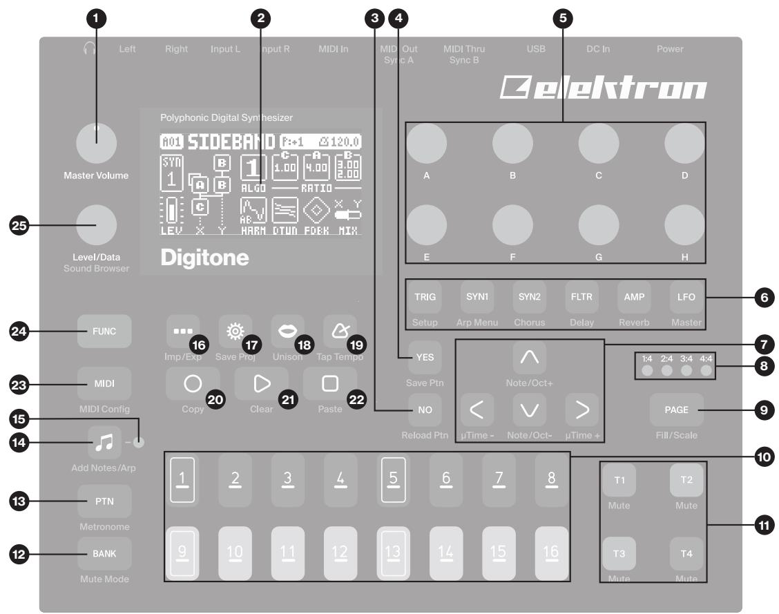
- MASTER VOLUME sets the volume for the main outputs and the headphones output.
- Screen.
- [NO] key. Used for exiting an active menu, backing one step and negating. The secondary function is a reload from the temporary save of the active pattern.
- [YES] key. Used for entering sub-menus, selecting and confirming. The secondary function is a temporary save of the active pattern.
- DATA ENTRY knobs A-H. Used for setting parameter values. Press and turn the knobs to change values in larger increments.
-
[PARAMETER] keys access the PARAMETER pages of the active track. The color of the keys indicates if the page is active (red/turquoise) or inactive (off).
-
[TRIG PARAMETERS] accesses parameters such as NOTE, VELOCITY, and other trig related parameters. The secondary function accesses the SOUND SETUP menu.
- [SYN1] accesses the SYN1 pages. Here you can find parameters related to the FM engine. For MIDI tracks this page has parameters such as CHANNEL, PROGRAM, and AFTERTOUCH. The secondary function accesses the ARPEGGIATOR menu.
- [SYN2] accesses the SYN2 pages. Here you can find further parameters related to the FM engine. The secondary function accesses the CHORUS page.
- [FLTR] accesses the FILTER pages. Here are the parameters for the base-width and multimode filters. On MIDI tracks you find the CC value settings here. The secondary function accesses the DELAY page.
- [AMP] takes you to the AMP page, where you find parameters for the amplitude envelope and effect sends. On MIDI tracks you find the CC select settings here. The secondary function accesses the REVERB page.
-
[LFO] accesses the LFO parameters for both synth and MIDI tracks. The secondary function accesses the MASTER page.
-
The [ARROW] keys. Used for navigation and for setting parameter values. In menus, they are called [UP], [DOWN], [LEFT], and [RIGHT].
-
LEDs indicate how many pattern pages the active pattern consists of and which pattern page is currently active. The LED flashes on the pattern page that is currently playing. - [PAGE] selects the active pattern page, if the pattern has more than 16 steps. The
LEDs indicate how many pattern pages the active pattern consists of and which pattern page is currently active. The LED flashes on the pattern page currently playing. The secondary function accesses the SCALE menu. This key also activates Fill Mode (when GRID RECORDING mode is not active). - [TRIG] keys enter or remove sequencer trigs, and parameter locks, in combination with the DATA EN-TRY knobs. They also select, banks, and patterns, in combination with the [PTN], and [BANK] keys. The [TRIG] keys also function as a keyboard to play the Digitone or to input notes to the sequencer. The [TRIG] keys lights indicate trigs on the sequencer by lit red keys, while flashing red keys indicates parameter locks, in GRID RECORDING mode. When a pattern is playing, or when LIVE RECORDING is enabled, a light “runs” along the 16 steps of the sequencer across all (up to four) pages at the set tempo.
- [TRACK] keys. Selects which track to be active. The secondary function mutes the track.
- [BANK] selects bank A–H in combination with the [TRIG 9–16] keys. The secondary function accesses the MUTE Mode.
- [PTN] selects pattern 1–16 in combination with the [TRIG 1–16] keys. The secondary function opens the METRONOME menu.
- [NOTE] opens the KEYBOARD SETUP menu where you can view and edit note related settings such as transpose, scale, and chords. The secondary function toggles the arpeggiator on and off. This key is also used to add notes using the TRACK NOTE menu in the sequencer.
LED indicates the arpeggiator's on/off status. - [SONG MODE] ☐ opens SONG mode screen where different SONG mode related actions are performed. The secondary function accesses the Import/Export menu.
- [SETTINGS] 📋 opens the SETTINGS menu that contains the management of projects, MIDI configuration, and the System settings. The secondary function saves the current project.
- [VOICE] 📋 opens the VOICE menu where you handle the track's voice allocation. The secondary function toggles unison on/off.
- [TEMPO] ☑ opens the TEMPO menu where you can adjust the global/pattern tempo and also adjust the swing. The secondary function makes it possible to tap the tempo.
- [RECORD] key. Activates/deactivates GRID RECORDING mode. Keep [RECORD] pressed, then press [PLAY], to activate LIVE RECORDING mode. Keep [RECORD] pressed, then press [STOP], to activate STEP RECORDING mode. The secondary function is a copy operation.
- [PLAY] starts the sequencer playback. Pressing [PLAY] a second time pauses playback. The secondary function is a clear operation.
- [STOP] stops playback. The secondary function is a paste operation.
- [MIDI] activates the MIDI editing mode where you can edit the MIDI tracks. A lit [MIDI] key indicates the MIDI editing mode is active. The secondary function opens the MIDI CONFIG menu.
- [FUNC] key. Press and hold [FUNC], and then press another key to access the secondary function of that key. The turquoise text on the Digitone front panel shows the keys secondary functions.
- LEVEL/DATA sets the overall volume level of the active track. You can also set parameters and scroll through lists. The secondary function opens the SOUND BROWSER.
3.2 REAR CONNECTORS

- POWER Switch for turning the unit on and off.
- DC In Input for power supply. Use the included PSU-3/b/c power adapter, connected to a power outlet.
- USB For connecting the unit to a computer. For MIDI-control or Overbridge use. Use the included A to B USB 2.0 connector cable to connect to a computer host.
- MIDI THRU/SYNC B, Forwards data from MIDI IN. Can also be configured to send DIN sync to legacy instruments. Use a standard MIDI cable to connect another MIDI device in the chain.
- MIDI OUT/SYNC A, MIDI data output. Can also be configured to send DIN sync to legacy instruments. Use a standard MIDI cable to connect to MIDI In of an external MIDI device.
- MIDI IN, MIDI data input. Use a standard MIDI cable to connect to MIDI Out of an external MIDI device.
- INPUT L/R, Audio inputs. Use a 1/4" mono phone plug (unbalanced connection).
- OUTPUT L/R, Main audio outputs. Use either 1/4" mono phone plug (unbalanced connection) or 1/4" Tip/Ring/Sleeve phone plug (balanced connection).
- HEADPHONES, Audio output for stereo headphones. Use 1/4" Tip/Ring/Sleeve phone plug.
3.3 SETTING UP AND STARTING THE DIGITONE
Make sure you place the Digitone on a stable support, such as a sturdy table, with sufficient space for the cables. Make sure to switch off all devices before you connect the Digitone to other devices.
- Plug the supplied DC adapter into a power outlet and connect the small plug to the 12 V DC In on the Digitone.
- Connect OUTPUT L/R from the Digitone to your mixer or amplifier.
- To control the Digitone from a computer, connect a USB cable between the computer and the USB connector of the Digitone.
- If you want to use MIDI to control the Digitone, connect the MIDI OUT port of the device you wish to send data from to the MIDI IN port of the Digitone. The MIDI THRU port duplicates the data arriving at the MIDI IN port so that it can forward data to other MIDI units. If you want to use Digitone to control other devices, connect the MIDI OUT port of the Digitone to the MIDI IN port of the of the device you want to control.
- Connect an audio source to INPUT L/R or via USB if you want to process audio from external sources.
- Switch on all units. Press the POWER switch located at the back of the Digitone to switch it on.
4. DIGITONE SOUND ARCHITECTURE
The illustrations below show the Digitone sound architecture, with its eight audio voices, three send effects (chorus, delay, and reverb) and master effect (overdrive).
4.1 AUDIO VOICES

4.2 EFFECTS


5. OVERVIEW OF THE DIGITONE DATA STRUCTURE
The illustration below outlines the Digitone's data structure.

5.1 +DRIVE
The +Drive is a non-volatile memory capable of storing up to 128 projects. The +Drive also holds +Drive Sound library, with the capacity of storing 2048 Sounds. Every project has access to these Sounds.
5.2 DATA STRUCTURE
5.2.1 PROJECT
A project contains 128 patterns. The project also stores general settings and states. The currently loaded project becomes the active working state of the Digitone. From here it is possible to edit the patterns and Sounds of the project. Every time the Digitone is switched on, it boots to the active working state, the active project. Projects are saved, loaded and managed in the SETTINGS menu. For more information, please see “14. SETTINGS MENU” on page 65.
5.2.2 PATTERNS
The patterns are the primary data container for the Digitone. 16 patterns are available for each of the eight banks, which means that 128 patterns are available for each project. A pattern contains up to four sounds (one for each synth track), sequencer data like trigs and parameter locks. It also contains the settings on the TRIG page and BPM, length, swing and time signature settings. The pattern also contains all the parameter settings for the four MIDI tracks. For more information, please see “10. THE SEQUENCER” on page 32.
5.2.3 SOUNDS
A Sound is a collection of the synth track settings in the SYN1, SYN2, FLTR, AMP, and LFO PARAMETER pages. Sounds can be stored either in the Sound pool of the active project or the +Drive Sound library. The Sound pool holds up to 128 Sounds and the +Drive library holds up to 2048 Sounds. You can use the SOUND MANAGER to manage sounds. For more information, please see “14.4.2 SOUND MANAGER” on page 69, “9. PATTERNS AND SOUNDS” on page 27, and “11. SYNTH TRACK PARAMETERS” on page 46.

A Sound imported to a pattern, becomes an independent copy of the Sound on the +Drive and is not linked to the original Sound on the +Drive. Instead, it becomes a part of the pattern.
5.3 ABOUT THE TRACKS
5.3.1 THE SYNTH TRACKS
The Digitone has four synth tracks. Each synth track holds one Sound. The Sound contains the settings in the PARAMETER pages (SYN1, SYN2, FLTR, AMP, and LFO) together with the settings in the SOUND SETUP menu and the ARPEGGIATOR menu.
Press one of the [T1-4] keys to select which synth track to edit.
5.3.2 THE MIDI TRACKS
The Digitone also has four MIDI tracks. They are used to control external MIDI equipped gear. Each MIDI track can trigger a chord of up to eight notes with adjustable parameters such as velocity and length, control pitch bend and aftertouch, as well as eight freely assignable MIDI control change parameters (MIDI CCs). For more information, please see “12. MIDI TRACK PARAMETERS” on page 56. A MIDI track can have any MIDI channel assigned to it, and several tracks can share the same channel. If several tracks are assigned to the same MIDI channel the track with the lowest number has priority regarding parameter conflicts.
The MIDI tracks function almost the same way as the synth tracks. Parameter locks, LFO modulation, copy and paste commands are available. Each MIDI track also features micro timing, individual track length, and time signature settings. The main difference is that the MIDI tracks do not generate any sound and the sequencer data instead transmits through the MIDI OUT or USB ports.
Press the [MIDI] key and then press one of the [T1-4] keys to select which MIDI track to edit.
5.3.3 EDITING THE TRACKS
The six [PARAMETER] keys open parameter pages which is where you edit the tracks.
- The TRIG page contains different parameters such as NOTE, VELOCITY, TRIG CONDITION and other trig related parameters. The TRIG page parameters are not saved as a part of the Sound but as a part of the pattern.
- The SYN1 page hosts the parameters that controls various parameters of the FM synthesis. For MIDI tracks, this page contains parameters such as CHANNEL, PROGRAM, and AFTERTOUCH.
- The SYN2 page controls further parameters of the FM synthesis.
- On the FLTR page, you find parameters for the for the bandpass and multimode filters. On MIDI tracks you find the CC value settings here.
- The AMP page for synth tracks hosts parameters for the amplitude envelope and effect sends. On MIDI tracks you find the CC select settings here.
• Finally, the LFO page hosts LFO parameters for the active track.
Use the DATA ENTRY knobs A-H to edit the corresponding parameters. Press and turn a knob to adjust its parameter in larger increments. Press and hold a [PARAMETER] key to see the values for all parameters on that page. For more information, please see “11. SYNTH TRACK PARAMETERS” on page 46, and “12. MIDI TRACK PARAMETERS” on page 56.
6. INTERACTING WITH THE DIGITONE
The screen shows all the information needed for real-time interaction and editing on the Digitone. The eight DATA ENTRY knob parameters shown varies depending on which parameter page you have selected. Below is the main interface screen of the SYN1 page.

- Bank and pattern.
- Pattern name.
- Pattern/Track transpose.
- Tempo.
- Eight track parameters. They show what parameters the DATA ENTRY knobs control and the current parameter values.
- FM algorithm (Displayed on the SYN1 and SYN2 pages).
- Track volume level. Use the LEVEL/DATA knob to change the level.
- Track number and track type. Synth (SYN) track or MIDI (MID) track.

The Digitone features a screen saver that dims the screen after 5 minutes of inactivity and turns off the screen after 60 minutes. Press any key or move any controller to wake up the screen.
6.1 SCREEN NAVIGATION
Use the [ARROW] keys [UP], [DOWN], [LEFT] or [RIGHT] to navigate menus or sub-menus. The LEVEL/DATA knob is used to scroll through menus and lists quickly.
[YES] is used to affirm, select, enter sub-menus and tick/untick boxes.
[NO] is used to negate, deselect or go back one or more steps.

When in a menu or sub-menu, the [NO] key can be used to go back, one step at a time, all the way to the main screen.
6.2 PARAMETER EDITING
The DATA ENTRY knobs are used to change the values of the track parameters. The positions of the parameters on the screen correspond to the physical locations of the knobs on the front panel. Some of the parameters on the screen tell you what DATA ENTRY knob controls that particular parameter.
For example “(E).”
- The parameters are adjusted in larger increments if you press down the DATA ENTRY knob while turning it. This function makes it quicker to sweep through the whole parameter range.
- Press DATA ENTRY knob + [NO] to reset the parameter to the default value.
- Press [PARAMETER] + [PLAY] to reset all the parameters on the parameter page to default values.
- Press and hold a [PARAMETER] key to see the values for all parameters on that PARAMETER page.
6.2.1 PARAMETER VALUE JUMP
Pressing [FUNC] while editing certain parameters makes the parameter values jump to appropriate positions. The Delay time, for example, jumps between 16, 32, 64 and 128.
6.2.2 CONTROL ALL
If you press and hold [MIDI] and change a parameter setting, this change affects this parameter in all the synth tracks in the pattern. Press [NO] before you release [MIDI] to revert the parameter changes. The control all functionality is not available for the MIDI tracks.
6.2.3 [FUNC] KEY PRESS COMBINATIONS
The standard way to use the [FUNC] key in combination with other keys, is to press and hold [FUNC] and then press the second key in the combination. For some key combinations, it is also possible to access a sub-menu by pressing and holding [FUNC] + second key for a second.
6.3 QUICK SCROLLING
Scroll through menus using the LEVEL/DATA knob. Quick scrolling is possible on many menus. Press [FUNC] + the [UP] or [DOWN] keys to move the cursor one menu page.
6.4 COPY, CLEAR, AND PASTE
Copy, clear and paste commands are available in many contexts. Press [FUNC] + [RECORD] to copy. Press [FUNC] + [STOP] to paste. Press [FUNC] + [PLAY] to clear. Repeat the key press combination to undo the paste and clear operations. Please see the different sections in the manual for more information on when these commands are available.

The copy clipboard can only hold one item at a time. When you perform a copy command, the item copied replaces any earlier copied items. For example, you can not have both a trig and a pattern copied at the same time.
6.5 THE NAMING SCREEN
The naming method is identical for the various naming situations that appear when you save sounds, projects et cetera.

The [LEFT] and [RIGHT] arrow keys are used to navigate between the characters. Turning the LEVEL/DATA knob or pressing the [UP] or [DOWN] arrow keys selects the characters. [FUNC] + [NO] erases letters. [FUNC] + [YES] inserts space.
6.5.1 NAMING POP-UP MENU
A convenient way of naming is to open a pop-up menu that shows all available letters, symbols, and digits. Press and hold the [FUNC] key when you are on the NAMING screen to access the NAMING POP-UP menu.

Keep [FUNC] pressed and use the [ARROW] keys to highlight the character you want to insert. Once there, release [FUNC] to add the character.

Copy, paste, and clear commands are available on the NAMING screen.
6.6 OVERBRIDGE

The Overbridge software suite enables a tight integration between the Digitone and a computer DAW software.
When using Overbridge, the user interface for the Digitone presents itself as a plug-in window in your DAW. Access, edit and automate parameters for sound shaping on screen. Always find your device preset parameters in the same state as you left them when you return to your DAW project, with the useful total recall functionality.
Read more about Overbridge use and availability on the Elektron website: https://www.elektron.se/overbridge/
6.7 CLASS COMPLIANT DEVICE
The Digitone is a class compliant device (also known as plug-and-play). It means it does not require any extra drivers to connect to your computer or other USB class compliant hosts.
The Digitone can, therefore, stream audio and MIDI directly over USB to and from supported computers/phones/tablets. It opens up several exciting possibilities of what you can do with your device, for example, record audio from your device directly over USB in your DAW. For more information, please see “14.10.1 USB CONFIG” on page 78.
6.8 BACKING UP THE DIGITONE
It is always recommended to make regular backups of your data. Backups are also a convenient way to share your projects and Sounds with other users. To make backups and transfer files to and from your Elektron device, you should use Transfer, a free application that you can download from the Elektron site https://www.elektron.se/support. The application is available for both Windows and macOS.
6.8.1 BACKING UP PROJECTS AND SOUNDS
You can backup up your projects and Sounds from your Elektron device to a computer. Here is the general procedure for how to back up your device:
- Connect the Elektron device to the computer via USB.
- Open the Transfer application on your computer, and then select the USB MIDI port(s) for your device on the CONNECTION page, and then click "CONNECT" next to your device under AVAILABLE DEVICES.
- In Transfer, click the EXPLORE tab to open the EXPLORE page.
- On the EXPLORE page top left side of the drop-down menu, make sure "MY COMPUTER" is selected.
- On the top right side, in the drop-down menu, select the type of file you want to transfer.
- In the window on the right, navigate to the files or folders you want to transfer
- Drag and drop the files or folders to your preferred location under "MY COMPUTER."
6.8.2 TRANSFERRING BACKED UP FILES TO YOUR ELEKTRON DEVICE
Use the EXPLORE page in Transfer to transfer previously backed up files to your Elektron device from a computer.
- Connect the Elektron device to the computer via USB.
-
Open the Transfer application on your computer and then select the USB MIDI port(s) for your device on the Transfer CONNECTION page. Click "CONNECT" next to your device under AVAILABLE DEVICES.
-
In Transfer, click the EXPLORE tab to open the EXPLORE page.
- On the top right side, in the drop-down menu, select the type of file you want to transfer.
- On the top left side in the drop-down menu, make sure "MY COMPUTER" is selected.
- Under "MY COMPUTER," navigate to the files or folders you want to transfer.
- Drag and drop the files or folders to your preferred location on your device.
- Depending on what file type you send, you might encounter pop-up windows asking you to decide what files you want to send and how you want to organize them.
7. QUICK START
This quick start guides you through some of the basic operations to start using the Digitone right away. First, connect it as described in section “3.3 SETTING UP AND STARTING THE DIGITONE” on page 14.
7.1 PLAYING THE FACTORY PRESET PATTERNS
You can find a number of preset patterns and sounds in the Digitone. Follow the instructions below to get started exploring your new instrument.
- Press [BANK] and then press [TRIG 9] key to select bank A. The screen reads "BANK A : SELECT PTN".
- Press [TRIG 1] key to select the first pattern of bank A.
- Press [PLAY] to listen to pattern A01.
- Press [PTN] and then press [TRIG 2] key to select pattern A02. It starts once pattern A01 has reached its end. Select pattern A03 by pressing [PTN] and then press [TRIG 3] key, and so on.
- Press [STOP] to stop playback.
7.2 USING THE TRIG KEYS TO PLAY THE DIGITONE
You can use the [TRIG] keys to play any synth track Sound manually.
- Make sure you are not in GRID RECORDING mode, or MUTE mode.
- Press [T1-4] keys to select the synth track you wish to play manually. The [TRIG] keys are lit up in a pattern that resembles an octave of a piano keyboard layout. Only lit keys are playable.
- Play the [TRIG] keys. The active track Sound is pitched differently for each of the playable keys. Press the [ARROW] keys [UP] or [DOWN], to transpose the virtual keyboard up or down one octave.
For more information, please see "8.5.1 KEYBOARD MODE" on page 24.
7.3 CHANGING SOUNDS
Each of the four synth tracks contains one Sound. You can use the SOUND BROWSER to preview and load Sounds to the synth tracks.
- Double-press [T1-4] key to open the SOUND BROWSER. You can also press [FUNC] + TRACK LEVEL to access the SOUND BROWSER
- The SOUND BROWSER shows a list of all Sounds residing in either the +Drive Sound library or the Sound pool. (You can press [BANK] + [TRIG 9–16] if you want to load a Sound from another Sound bank in the +Drive Sound library). Turn the LEVEL/DATA knob or press [UP]/[DOWN] to scroll through the list. You can preview a Sound by highlighting it in the list and use the [TRIG] keys to play the Sound. Press [NOTE] + [UP]/[DOWN] to change octave up and down on the Sound you preview.
- Press [YES] to load the highlighted Sound.
7.4 USING MUTE MODE
You can mute any of the sequencer tracks in this mode. You can access all tracks simultaneously.
- Make sure a pattern is playing.
- Press the [FUNC] + [BANK] key to enter MUTE mode.
- Press any of the [TRACK] keys to mute the corresponding track. Press again to unmute. The light of the [TRACK] keys indicates the mute status. Unlit keys are muted tracks. Lit keys are active tracks.
For more information, please see "8.5.2 MUTE MODE" on page 25.
7.5 TEMPO
Press the [TEMPO] key to open the TEMPO menu where you can change the BPM setting. Use the LEVEL/DATA knob to change tempo. Pressing the knob while turning it changes the tempo four BPM at a time. The [ARROW] keys [UP] or [DOWN] change the tempo in fractional steps. Note that you can choose between a global tempo or use a separate tempo for every pattern. Press [FUNC] + [YES] to switch between GLOB-AL and PATTERN tempo mode. On the main interface screen, you can also press and hold the [ARROW] keys [LEFT] or [RIGHT] to nudge the tempo 10% up or down temporarily. Release the key to revert to the original tempo.
To tap a tempo setting, press and hold the [FUNCTION] key and tap the [TEMPO] key in a steady rhythm. The average tempo of the taps calculates after four consecutive taps. By continuing tapping, the average tempo keeps on updating.
When in the TEMPO menu (and with GLOBAL tempo mode selected), holding [FUNC] while turning the LEVEL/DATA knob will not change the tempo to the selected value until the [FUNC] key is released. While doing this, "PREP." will flash in the bottom left corner of the screen.
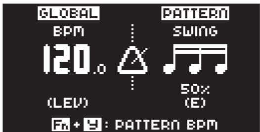

Nudging the tempo is very handy when manually syncing Digitone to a turntable or an external sound source. Note that you do not need to be in the TEMPO menu to perform tempo nudging.
7.6 EDITING PARAMETERS
Each track has six PARAMETER pages. Press [PARAMETER] keys TRIG, SYN1, SYN2, FLTR, AMP, and LFO to access the different PARAMETER pages. These parameters affect the sound and signal in various ways.
- Make sure a pattern is playing.
- Press [T1-4] to select one of the four synth tracks.
- To change, for example, the cutoff of the filter, press the [FLTR] key to open the FILTER page. The parameter labeled FREQ changes the cutoff of the filter. Turn DATA ENTRY knob E to change the parameter value, and hear how the sound is affected.
Try out the rest of the PARAMETER page parameters to explore a variety of sound shaping possibilities.

- After you edited the parameters of a Sound, you can save it to the +Drive. For more information, please see "9.4 SAVING A SOUND" on page 28.
- You can also randomize the parameter settings on a specific PARAMETER page on a Synth track. Press [PARAMETER] key + [YES] to randomize all parameters on that page. Every time you press this key combination, the parameters randomize in a new way.
- Press [PARAMETER] page key + [NO] to reset the PARAMETER page to its last saved state.
8. DIGITONE CONTROLS
8.1 TRIG KEYS
The [TRIG] keys have several uses, including, playing the active synth track sound (not in GRID RECORDING or MUTE mode). The [TRIG] keys also place trigs in GRID RECORDING mode. When pressed in combination with the [PTN] and [BANK] keys, they select patterns and banks. The [TRIG] keys light up to indicate the position of placed trigs and to indicate the selected bank and pattern.
8.2 ROTARY ENCODERS
The MASTER VOLUME is an absolute potentiometer. The LEVEL/DATA and DATA ENTRY knobs (with which you set various parameter values) are relative encoders which may spin any number of turns. Pressing and turning these encoders changes their associated values at a higher speed.
8.3 KEY BEHAVIOR
As a group, the [TRACK] keys have radio button functionality, i.e., when a new track is set to be active, the previous one is simultaneously deactivated. You can only select one track at a time. Likewise, the group consisting of the six [PARAMETER] keys have radio button functionality.
The [FUNC], [PTN], and [BANK] keys are always used in combination with other keys.
8.4 MIDI NOTES
Sending MIDI note values from an external MIDI device (a MIDI keyboard or a computer, for example) connected to the Digitone via a standard MIDI cable or a USB 2.0 A to B connector cable can trigger some of the Digitones functions.
MIDI note numbers 0–127 (corresponding to notes C0–G10, the first through to eleventh octaves in the MIDI range) triggers the Sound of the active track.
MIDI program change messages 0–127 will select pattern 1–128 (A01–H16) on the Digitone. Additionally, MIDI CC and NRPN messages can be sent to control various aspects of the Digitone. For more information, please see “APPENDIX B: MIDI IMPLEMENTATION” on page 95.
8.5 MODES
8.5.1 KEYBOARD MODE
The KEYBOARD mode is the default mode of the Digitone and is always active unless you are in GRID RECORDING or MUTE mode. In this mode, you can use the [TRIG] keys to play the Sound of the active audio track (or send MIDI notes if you have an active MIDI track). With KB SCALE set to CHROMATIC and KB FOLD set to OFF the [TRIG] keys will light up in a pattern that resembles an octave of a piano keyboard layout. Only lit keys are playable. Press one of the [T1-4] keys to select the track you wish to play.
Press the trig keys to change the note pitch of the sound. The range from [TRIG 9] key to [TRIG 16] key is one octave. The whole range for both synth tracks and MIDI tracks spans eleven octaves. Press the [ARROW] keys [UP] or [DOWN], to transpose the virtual keyboard up or down one octave.
Notes triggered can be recorded on the sequencer in LIVE RECORDING mode. Find out how this is done in section “10.2.5 LIVE RECORDING MODE” on page 34.
The active state of KEYBOARD mode (the portion of the keyboard currently visible on the [TRIG] keys) is not stored per pattern but stays in the state as it was last set.

You can also use an external keyboard or controller to play the active tracks sound. Connect the keyboard to the Digitone and configure the external keyboard and the Digitone MIDI AUTO Channel (SETTINGS > MIDI CONFIG > CHANNELS) to the same MIDI channel. Then play the keys on the external keyboard to play the active tracks sound. In this way you can play the active track's sound even if the Digitone is not in KEYBOARD mode.
8.5.2 KEYBOARD SETUP MENU
Press [NOTE] to open the KEYBOARD SETUP menu. Here you get a graphical view of which notes the [TRIG] keys play. Press [UP]/[DOWN] to transpose the keyboard up or down an octave. In this menu, you can also set different musical scales, and select the scales key. Press [T1-4] to select which track to edit. Use the DATA ENTRY knobs to change the settings. Press [NO] to exit the menu. The settings are stored in the active pattern.

SCALE sets the tracks scale. This is done by limiting which keys are playable on the Digitone keyboard and from external MIDI devices that sends on the Digitone's AUTO channel. For a list of all selectable keyboard scales, please see "APPENDIX D: KEYBOARD SCALES" on page 100.
ROOT sets the root note for the chosen scale.
CHORD adds a three-note chord based on the SCALE and ROOT settings when you press a key on the Digitone keyboard. (OFF, ON) If you set SCALE to CHROMATIC you have a selection of different chords to choose from. (MAJ, MIN, 7TH, MIN7, MAJ7, DIM, DIM7)
TRANSPOSE transposes the track up or down in semitone steps. This parameter adds an offset value and the actual note values in the sequencer do not change. Use DATA ENTRY knob H to change the setting, and then press [YES] to confirm the setting. You can also use DIRECT TRACK transpose to transpose a track. For more information, please see "10.9.8 DIRECT TRACK TRANSPOSE" on page 42. (-36–+36)
KB FOLD When set to ON, KB FOLD changes the way the notes are laid out on the [TRIG] keys and how they are played from external MIDI devices. Now all the [TRIG] keys trigger a note. The [TRIG 9] key plays the lowest note of the selected octave, root note and scale. The notes are then played upwards through the scale to [TRIG 16] and then further upwards on [TRIG 1–8]. When a scale contains less than eight notes in an octave, the “remaining” [TRIG] keys on the lower row will play the same notes as the first [TRIG] keys on the upper row. Blue [TRIG] keys signal that they contain notes that are one or more octaves distanced from each other.
In the following example of the whole tone scale [TRIG 15–16] keys play the same notes as the [TRIG 1–2] keys. [TRIG 1] and [TRIG 15] both plays a note that is one octave above [TRIG 9]. [TRIG 7] plays a note that is two octaves above [TRIG 9].


You can also use an external keyboard to play the active tracks Sound. Connect the keyboard to the Digitone and configure the external keyboard and the Digitone MIDI Auto Channel (SETTINGS > MIDI CONFIG > CHANNELS) to the same MIDI channel. Then play the keys on the external keyboard to play the active tracks Sound. You can play the active track's Sound even if the Digitone is not in KEYBOARD mode.
8.5.2 MUTE MODE
You can use MUTE mode to mute any of the 8 sequencer tracks. Press [FUNC] + [BANK] to enter the MUTE mode. Press any of the [TRACK] keys to mute the corresponding track. Press again to unmute. Press [MIDI] to access the MIDI tracks. The color of the [TRACK] key indicates the track's mute status. Unlit keys signify muted tracks. Lit keys signify unmuted tracks.
There are two different versions of MUTE mode on the Digitone:
- GLOBAL MUTE MODE In GLOBAL MUTE mode, the muted tracks are muted in all patterns, and the [TRACK] keys are lit green. If a track is muted in GLOBAL MUTE mode, the track's [TRACK] key is lit green when the pattern plays.
Press [FUNC] + [BANK] to enter GLOBAL MUTE mode.
Press [FUNC] + [BANK] to exit GLOBAL MUTE mode.
- PATTERN MUTE MODE In PATTERN MUTE mode, the muted tracks are muted only in the active pattern, and the [TRACK] keys are lit magenta. If a track is muted in PATTERN MUTE mode, the track's [TRACK] key is lit magenta when the pattern plays.
Press [FUNC] + double-press [BANK] to enter PATTERN MUTE mode.
Press [FUNC] + [BANK] to exit PATTERN MUTE mode.
The GLOBAL MUTE mode settings are saved together with the project. The PATTERN MUTE mode settings are saved together with the pattern.
Tracks that are muted in both GLOBAL MUTE mode and PATTERN MUTE mode are shown with blue lit [TRACK] keys.

- You can also use QUICK GLOBAL MUTE to mute and unmute sequencer tracks globally. Press and hold [FUNC] and then press the [TRACK] keys to mute or unmute tracks.
- Digitone remembers the last used version of MUTE mode and accesses this version first when you press [FUNC] + [BANK] or [FUNC] + [TRACK].
- You can also use QUICK PATTERN MUTE to mute and unmute sequencer tracks in the active pattern. Press and hold [PTN] and then press the [TRACK] keys to mute or unmute tracks. This shortcut always mutes the track in PATTERN MUTE mode.
9. PATTERNS AND SOUNDS
The patterns are the primary data container for the Digitone. Sixteen patterns are available for each of the eight banks, which means that 128 patterns are available for each project. A pattern contains up to four sounds (one for each synth track), sequencer data like trigs and parameter locks. It also contains the default settings on the TRIG page and BPM, length, swing and time signature settings. A pattern also contains all the parameter settings for the four MIDI tracks.
Each of the synth tracks can contain one Sound. A Sound that is imported from the +Drive or Sound pool to a pattern becomes part of the active pattern. Any changes made to a Sound will therefore not affect the stored Sound. It only affects the Sound in the active pattern. You can export (and in that way save) a Sound from the active pattern to the +Drive. For more information, please see “14.4.2 SOUND MANAGER” on page 69. Use the SOUND BROWSER to load a Sound to a track. For more information, please see “14.4.1 SOUND BROWSER” on page 68.

When you import a sound to a pattern, it becomes a copy of the Sound on the +Drive. The Sound is not linked to the original Sound stored on the +Drive. Instead, it fully becomes a part of the pattern.
A Pattern contains:
• Four synth track Sounds.
- All parameter settings for the four MIDI tracks.
- Sequencer data like trigs and parameter locks.
- The settings on the TRIG PARAMETERS page, BPM, length, swing and time signature settings.
A Sound contains:
- The SYN1, SYN2, FLTR, AMP, and LFO PARAMETER pages settings for the synth track.
- All the settings in the SOUND SETUP menu and the ARPEGGIATOR menu.
9.1 THE +DRIVE SOUND LIBRARY AND THE SOUND POOL
Sounds can be loaded to a pattern from either the +Drive Sound library or the Sound pool of the active project. The difference between the two is that the +Drive Sound library has the capacity of 2048 Sounds, available to all projects, while a Sound pool is a part of a project and limited to 128 Sounds. The primary benefit of Sounds loaded to the Sound pool is the possibility for them to be Sound locked. This feature is not available for the Sounds in the +Drive Sound library. For more information, please see “10.9.2 SOUND LOCKS” on page 40.
9.1.1 ADDING SOUNDS TO THE SOUND POOL
You must first add Sounds to the Sound pool to be able to perform Sound locks.
- Press [FUNC] + [SONG MODE] to open the IMPORT/EXPORT menu.
- Select MANAGE SOUNDS, and then press [YES] to open the SOUND MANAGER.
- Select the Sounds you want to add to the Sound pool by highlighting them and pressing [YES].
- Press [RIGHT] to open the SOUND OPERATIONS menu.
- Select COPY TO ... and then press [YES].
- Select SOUND POOL, and then press [YES].
9.2 PLAYING A SOUND
Press the [TRIG] keys to play the Sounds of the four synth tracks of the active pattern. The [TRIG] keys briefly lights up when pressed.
PLAYING A SOUND WITH AN EXTERNAL MIDI UNIT
The Sounds can also be played using an external MIDI device connected to Digitone. The MIDI channels for of each of the synth tracks can be assigned in the MIDI CHANNELS menu, covered in the section “14.5.3 CHANNELS” on page 72. You can also use an external MIDI unit to play the Sound. For more information, please see “8.5.1 KEYBOARD MODE” on page 24.
9.3 EDITING A SOUND
Press [T1-4] to select the track which Sound you wish to edit. Any changes made to a Sound are stored as part of the active pattern.
Adjust the TRACK LEVEL of the active synth track with the LEVEL/DATA knob.
Edit a Sound by adjusting the parameters found on the PARAMETER pages. Press the [PARAMETER] page keys to access the PARAMETER pages. Use the DATA ENTRY knobs A-H to change the parameters. For more information, please see "11. SYNTH TRACK PARAMETERS" on page 46.
You can always reload the Sound from its last saved state. Press [T1-4] + [NO] to reload the Sound.
If you want to export (save) a particular Sound with all its current parameter settings, use the SOUND MANAGER. For more information, please see “14.4.2 SOUND MANAGER” on page 69.
The complete Sound, with all its parameter settings, may be copied to another track. Press [TRK 1–4] + [RECORD], and then press [TRK 1–4] + [STOP] to paste the sound to the selected track.
9.4 SAVING A SOUND
After you edited the parameters of a Sound, you can save it either to the +Drive or to the Sound pool. For more information, please see “9.1 THE +DRIVE SOUND LIBRARY AND THE SOUND POOL” on page 27.
9.4.1 SAVING A SOUND TO THE +DRIVE
A Sound that you save to the +Drive is available for any project.
- Press [FUNC] + [SONG MODE] to open the IMPORT/EXPORT menu.
- Select EXPORT SOUND, and then press [YES].
- Turn the LEVEL/DATA knob or use the [UP]/[DOWN] keys to select an empty slot to where you want to save your Sound, and then press [YES]. If you want to save your Sound to another bank, press [BANK] + [TRIG 9-16] to select a bank.
- On the NAMING screen, name your Sound and then press [YES]. For more information, please see "6.5 THE NAMING SCREEN" on page 19.
- On the TAGS screen, use the [ARROW] keys and [YES] key to select the appropriate tags for your sound, and then select
and press [YES].
9.4.2 SAVING A SOUND TO THE SOUND POOL
A Sound that you save to the Sound Pool is only available for the current project, but it can be Sound locked.
- Press [FUNC] + [SONG MODE] to open the IMPORT/EXPORT menu.
- Select MANAGE SOUNDS, and then press [YES] to open the SOUND MANAGER.
- Press [LEFT] to open the SORTING menu and select VIEW POOL, and then press [YES].
- Turn the LEVEL/DATA knob or use the [UP]/[DOWN] keys to select an empty slot to where you want to save your Sound.
- Press [RIGHT] to open the SOUND OPERATIONS menu.
- Select EXPORT TO HERE and then press [YES].
- On the NAMING screen, name your Sound and then press [YES]. For more information, please see "6.5 THE NAMING SCREEN" on page 19.
9.5 SOUND SETUP MENU
Press [FUNC] + [TRIG PARAMETERS] to open the SOUND SETUP menu. Here you can set a number of Sound related parameters. Use the [UP] and [DOWN] arrow keys to move between the options. Press [YES] to confirm your selection. Press [NO] to exit the menu.

9.5.1 KEY SCALING A
Key scaling sets the level of how much the modulation output from operator A is affected by what note you play on the keyboard. If you set key scaling to 0, the modulation level is the same for all keys. A high-
er setting decreases the modulation level more and more the higher you play the keyboard. A lower level of modulation decreases the complexity of the tone in the higher frequencies, which is a typical behavior in many acoustic instruments.
9.5.2 KEY SCALING B1
Same as KEY SCALING A, but for operator B1
9.5.3 KEY SCALING B2
Same as KEY SCALING A, but for operator B2
9.5.4 FILTER KEYTRACK
Keytrack lets the Multimode filter cutoff frequency follow the pitch of the Sound. A setting of 100 makes the filter track the oscillator frequency in note intervals. (0–100)
9.5.5 PORTAMENTO
Here you find settings related to the portamento. For more information, please see "11.2 TRIG PARAMETERS PAGE" on page 46.
- TYPE
TRACK. When you play notes, the pitch glides from the pitch of the last note played to the next new note played on the track.
VOICE When you play notes, the pitch glides from the pitch of the last note played by a specific voice to the pitch of the next new note played by the same voice.
LEGATO ONLY When playing notes, the pitch glides from the pitch of the last note played and held (the key pressed down and not yet released) to the pitch of the next new note played on the track.
• SLOPE
CONSTANT RATE. The pitch glides linearly at a constant rate. Longer glides take longer time to complete.
CONSTANT TIME The pitch glides linearly, but the glide is completed in a specific time, regardless of the interval between the start and end notes. Glides over wider note intervals, therefore, have a higher rate.
- AMOUNT
This setting enables partial glides where just the final part of the interval is included in the glide. For example, a setting of 100 gives a full glide from start to finish. Lower values start the glide closer to the goal pitch. With polyphonic portamento on chords, this results in a shorter and less messy glide.
• STYLE
GLIDE Ordinary continuous portamento.
GLISSANDO Quantizes the portamento to semitones.
• GATING
OFF The glide continues after the key is released.
ON The glide stops when the key is released.
9.5.6 PLAY MODE
Here you can set if a Sound is poly- or monophonic and if the LFOs for every voice are synced or not.
POLY The Sound is polyphonic, and the LFOs for each voice are running independently of each other.
POLY M.LFO In POLYPHONIC WITH MONO LFO mode, the Sound is polyphonic, and the LFOs for each voice are synced together with the first voice LFO. The LFO of the first voice played determines the cycle of the LFOs, and the subsequently played voices' LFOs are synced to this cycle. This makes the LFO behave like a single or monophonic LFO. This is useful, for example, if you want to use the LFO for a tremolo effect.
MONO The Sound is monophonic, and the envelope is always triggered by each note on/key press.
MONO LEG. In MONO LEGATO mode, the Sound is monophonic, but the envelopes are not triggered by a subsequent note on/key press if the first note is still held.

If you chose one of the monophonic settings for the track, it is displayed as a black dot next to the track name in the VOICE MENU. How many voices that are used to play a Sound is also affected by the LOCKED VOICES setting in the VOICE MENU. For more information, please see “10.5 VOICE MENU” on page 37.
9.5.7 MONO NOTE PRIO
Here you can set the note priority, i.e., what note is played if more than one note is played at the same time. This setting is only available If PLAY MODE is set to MONO or MONO LEG.
LAST gives priority to the last note played.
LOW gives priority to the lowest note played.
HIGH gives priority to the highest note played.
9.5.8 VELOCITY TO VOL
Selects how MIDI velocity affects volume when playing the Sound from a MIDI keyboard.
OFF means velocity does not affect the volume of the sound.
LOG applies a logarithmic velocity curve. The volume difference are greater between softer keyboard presses than between harder.
LIN applies a linear velocity curve. The volume difference between keyboard presses corresponds linearly to the force applied.
EXP applies an exponential velocity curve. The volume difference are greater between harder keyboard presses than between softer.
9.5.9 PITCH BEND DEPTH
Sets how much the pitch bend data from external MIDI devices affects the Digitone.
9.5.10 OCTAVE
Sets the base octave of the Sound. This setting makes it easier to play the sound at the “right” octave on the Digitone keyboard. It also makes Sound locking more practical since you can control the octave setting on the Sound and minimize the need to transpose the sequencer notes to make two or more Sounds work together.
9.5.11 PITCH BEND
Opens a menu where you can assign up to four PARAMETER page parameters to the pitch bend. The pitch bend from incoming MIDI sent to the Digitone from external devices affects the assigned parameters. Press [YES] to open the menu.
You can select parameters from the SYN1, SYN2, FLTR, AMP, and LFO PARAMETER pages. Turn the DATA ENTRY knobs A–D to select the track parameters that you wish to assign. Press [YES] to confirm the selection. Then use DATA ENTRY knobs E–H to set the modulation depth of the four track parameters. The depth is an offset of the original track parameter value.
Turn LEVEL/DATA to test your settings.

9.5.12 VELOCITY MOD
Opens a menu where you can assign up to four PARAMETER page parameters to the velocity parameter. Both the VEL parameter on the TRIG menu and the velocity of incoming MIDI notes sent to the Digitone from external devices affects the assigned parameters. Press [YES] to open the menu. Selecting parameters and setting modulation depth works in the same way as for PITCH BEND.
Turn LEVEL/DATA to test your settings.
9.5.13 MOD WHEEL
Opens a menu where you can assign up to four PARAMETER page parameters to the MIDI mod wheel command (CC #1). Press [YES] to open the menu. Selecting parameters and setting modulation depth works in the same way as for PITCH BEND.
Turn LEVEL/DATA to test your settings.
9.5.14 BREATH CONTROLLER
Opens a menu where you can assign up to four PARAMETER page parameters to the MIDI breath controller command (CC #2). Press [YES] to open the menu. Selecting parameters and setting modulation depth works in the same way as for PITCH BEND.
Turn LEVEL/DATA to test your settings.
9.5.15 AFTERTOUCH
Opens a menu where you can assign up to four PARAMETER page parameters to the MIDI aftertouch command. Press [YES] to open the menu. Selecting parameters and setting modulation depth works in the same way as for PITCH BEND.
Turn LEVEL/DATA to test your settings.
9.6 ARPEGGIATOR MENU
The ARPEGGIATOR menu controls the Sounds arpeggiator. The arpeggiator settings are part of the Sound and saved together with the Sound. The arpeggiator is not available for the MIDI tracks. Press [FUNC] + [SYN1] to open the ARPEGGIATOR menu. Press [T1-4] key to select the Sound whose arpeggiator are edited. Press [FUNC] + [NOTE] to toggle the ARPEGGIATOR on and off.

9.6.1 MODE
Activates the arpeggiator and controls how the arpeggiated notes are sorted.
OFF deactivates the arpeggiator.
TRUE plays the notes in the same order as they are inserted.
UP plays the notes in ascending order, from the lowest note to the highest, on a per octave basis.
DOWN plays the notes in descending order, from the highest note to the lowest, on a per octave basis.
CYCL plays the notes first in ascending order, then in descending order.
9.6.2 SPD
Speed sets the speed of the arpeggiator. It is synchronized to the BPM of the project. (1/1–1/96).
9.6.3 RNG
Range sets the octave range of the arpeggiator. After each completed arpeggiator cycle, the arpeggiated notes are transposed one octave up. When the notes have reached the octave offset specified by the RNG setting the notes are reset to their initial values. From there the octave transpose is started all over again.
9.6.4 LEN
Length controls the length of the arpeggiated notes.
9.6.5 ARP LENGTH
Turn DATA ENTRY knob F to select the length of the arpeggio. The max length is 16 sequencer steps.
9.6.6 OFFSET
Offset selects the offset (note) value of the chosen arpeggiator step in semi-tones. The offset is from the original note trig. The SCALE KEY settings found in the KEYBOARD SETUP menu affects the note values of the arpeggiated notes.
- Press [LEFT] or [RIGHT] to select which arpeggiator step to offset.
- Use DATA ENTRY knob E to set the offset.
- Press [DOWN] to deactivate an arpeggiator step. Press [UP] to activate an arpeggiator step that has been deactivated.
10. THE SEQUENCER
The sequencer store its information in patterns. A pattern controls the playback of the synth tracks, the MIDI tracks and various pattern-specific aspects of the tracks. Each of the eight banks, A to H, contains 16 patterns, which means 128 patterns are available for each project. For more information, please see “14.3 PATTERN” on page 66.
A pattern contains:
• The four track [T1-4] Sounds.
- The parameter settings on the TRIG, SYN1, SYN2, FLTR, AMP, and LFO pages.
- The parameter settings on the CHORUS, DELAY, REVERB, and MASTER pages.
• Quantization settings.
• Note trigs for all tracks.
- Lock trigs for all tracks.
- Sound locks
- Parameter locks.
• Length and time signature for the tracks.
10.1 BASIC PATTERN OPERATIONS
Digitone can seamlessly switch between patterns. Together with the ability to chain patterns, this is a handy feature when improvising live. For more information, please see “10.10 CHAINS” on page 43.
10.1.1 SELECTING BANK AND PATTERN
Press [BANK] and then press [TRIG 9–16] to select a bank. Then press [TRIG 1–16] to select a pattern. Press [PTN] and then press [TRIG 1–16] to select a new pattern in the current bank. When you press [BANK] or [PTN] you must choose a bank or pattern within four seconds for the change to take effect. A message on the screen indicates the four-second timeout. Press [PTN], [BANK], or [NO] to exit pattern or bank select.
White [TRIG] keys indicate pattern positions that contain data. A red [TRIG] key indicates the current active pattern. Empty patterns [TRIG] keys are unlit.
When a pattern is playing, and a new pattern is selected, the new pattern position is shown flashing in the upper left corner of the screen. Once the last step of the pattern has played, the new pattern starts, and the pattern position ceases to flash.

- Patterns can be changed while the sequencer is running.
- Patterns can be changed and queued by sending program change messages.
- It is possible to copy a pattern, and then paste it to one or several locations without leaving the active pattern. You can also clear one or several non-active patterns.
- To copy, press and hold [PATTERN] + [TRIG] key to select the pattern you wish to copy. Then press [RECORD]. Let go of the [TRIG] key and then press and hold the [TRIG] key(s) to where you want to paste the pattern. Finally, press and hold [STOP] to paste the pattern(s).
- To clear, press and hold [PATTERN] + [TRIG] key(s) to select the pattern(s) you wish to clear. Then press and hold [PLAY] to clear the pattern(s).
10.1.2 PATTERN CONTROL
Press [PLAY] to start the pattern playback. Press [STOP] to stop the playback. When a pattern plays, press [PLAY] to pause. When a pattern is paused, press [PLAY] to resume the playback. The audio is cut off, but effects like the delay continues until the delay repeats fades out. Quickly press [STOP] twice to stop playback of all tracks and the fade out of the send effects.
The
10.1.3 PATTERN TEMPO
You set the tempo in the TEMPO menu. Press [TEMPO] 🔒 to open this menu. For more information, please see “7.5 TEMPO” on page 22.
10.2 CREATING AND EDITING A PATTERN
Digitone has three main modes of input when you want to create or edit a pattern, GRID RECORDING mode, LIVE RECORDING mode, and STEP RECORDING mode.
10.2.1 TRIG TYPES
A trig is a sequencer event that you place where you want the sequencer to perform an action on the Digitone. There are two types of trigs available in both recording modes: Note trigs and Lock trigs.
• NOTE TRIGS trigger notes on synth tracks and MIDI tracks.
- LOCK TRIGS trigger parameter locks (but does not trigger notes). For more information, please see "10.9.1 PARAMETER LOCKS" on page 39.
Red [TRIG] keys indicates note trigs and yellow [TRIG] keys indicates lock trigs. Unlit [TRIG] keys indicate steps that do not contain any trigs. Trigs are added differently in the sequencer, depending on whether GRID RECORDING, LIVE RECORDING, or STEP RECORDING mode is active.
10.2.2 GRID RECORDING MODE
GRID RECORDING is a method of composing where you use the [TRIG] keys to add trigs.
- Press [T1-4] to select the track to which you want to add trigs. A green [TRACK] key light indicates the active track.
- Press [RECORD] to enter GRID RECORDING mode. The [RECORD] key lights up red to indicate that GRID RECORDING mode is active.
- Use the [TRIG] keys to place note trigs on the sequencer. The trigs note value is the value specified by the ROOT parameter in the TRIG PARAMETERS page. For more information, please see "11.2.1 ROOT" on page 46.
-
To add a lock trig, press [FUNC] + [TRIG].
-
Press the [TRIG] key of any of the previously entered trigs if you wish to remove the trig. Press a [TRIG] key of a trig and hold it slightly longer to prepare the trig for editing, rather than removing it.

- Add micro timing to a note trig by pressing and holding the [TRIG] key and then press the [LEFT]/[RIGHT] keys. For more information, please see “10.6 MICRO TIMING MENU” on page 38.
- Press [TRIG] + [YES] to preview a specific trig. The preview includes any parameter locks you have placed on that trig.
- If the pattern contains more than 16 steps, select the pattern page you want to edit by pressing the [PAGE] key. A fully lit
LED shows the active pattern page. - All trigs of a track can be shifted forwards or backward on the sequencer. While in GRID RECORDING mode, hold down [FUNC] while pressing the [LEFT] or [RIGHT] arrow keys to perform the trig shift.
10.2.3 GRID RECORDING USING TRACK NOTE METHOD
This is an alternative way to enter note trigs in GRID RECORDING mode that gives you more control over what note values you want to add to a specific step in the sequencer. For more information, please see "10.4 TRACK NOTE MENU" on page 36.

- Press [T1-4] to select the track to which you want to add note trigs and additional notes. A green [TRACK] key light indicates the active track.
- Press [RECORD] to enter GRID RECORDING mode. The [RECORD] key lights up red to indicate that GRID RECORDING mode is active.
- Press the [TRIG] key to where you want to add or remove notes + [NOTE]. A graphic keyboard appears on the screen where you can see all the notes on the chosen sequencer step. A key with a dot on the screen keyboard indicates added notes.
-
Press the [TRIG] keys to add notes with the corresponding note value. Press the key of a previously entered note if you wish to remove that note.
-
Press [YES] to enter the changes and then exit. Press [NO] if you wish to exit without making any changes.
10.2.4 GRID RECORDING USING QUICK NOTE METHOD
This is yet another alternative way to enter note trigs in GRID RECORDING mode that gives you better control over what note values you want to add to a specific step in the sequencer.
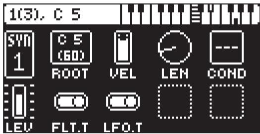
- Press [T1-4] to select the track to which you want to add note trigs and additional notes. A green [TRACK] key light indicates the active track.
- Press [RECORD] to enter GRID RECORDING mode. The [RECORD] key lights up red to indicate that GRID RECORDING mode is active.
- Press and hold (keep holding until step 8 of this procedure) the [TRIG] key to where you want to add, adjust or remove notes and then press [UP] or [DOWN] A graphic mini keyboard appears at the top the screen. The leftmost number is the active note. The number in brackets shows the number of notes on the sequencer step. Then follows the note value of the active note. A filled key on the screen keyboard shows the active note and the other notes are shown as dots.
- Use the [UP] and [DOWN] keys to adjust the value of the note. Press and hold [FUNCTION] and press [UP] or [DOWN] key to adjust the pitch one full octave up or down.
- Press [YES] to add a new note. Then use the [UP] and [DOWN] keys to move the added note to the desired note value.
- Use the [LEFT] and [RIGHT] keys to navigate to a previously added note and then press [UP] or [DOWN] to move the note. Note 1 is the root note. The other notes are offsets to the root note. If you adjust the root note value, the other notes moves along with it.
- Press [NO] if you wish to remove an already added note.
- Release the [TRIG] key to execute the Quick Note edit and then exit.

- You can use an external MIDI controller such as a keyboard to input NOTE and TRIG VELOCITY data when you are in GRID RECORDING mode. Just press and hold a [TRIG] key, and then play a note on the external keyboard. On MIDI tracks, you can add up to a eight note chord to every trig. The first note sets the TRIG VELOCITY value for all notes on the trig.
- If you use an external MIDI controller to record to the Digitone tracks, the sequencer receives data on the Auto MIDI channel and records on the active track. For more information, please see “14.5.3 CHANNELS” on page 72.
- All trigs of a track can be shifted forwards or backward on the sequencer. While in GRID RECORDING mode, hold down [FUNC] while pressing the [LEFT] or [RIGHT] arrow keys to perform the trig shift.
10.2.5 LIVE RECORDING MODE
LIVE RECORDING mode is the second method of adding trigs to the tracks. In this recording mode, the [TRIG] keys are played in real time to input trigs to the tracks. You can also turn the DATA ENTRY knobs to enter parameter locks in real time. Trigs input in LIVE RECORDING mode can be automatically quantized or not. Use the settings in the QUANTIZE menu to quantize non-quantized trigs after they are recorded. For more information, please see “14.3.1 QUANTIZE” on page 66.
- Press [T1-4] to select the track to which you want to add trigs. A green [TRACK] key light indicates the active track.
-
Press and hold [RECORD], then press [PLAY] to enter LIVE RECORDING mode. (Press [PLAY] twice while keeping the [RECORD] key pressed to activate/deactivate automatic quantization.) The sequencer starts to play, and the [RECORD] key starts to blink red.
-
Press the [KEYBOARD] or press the [TRIG] keys to enter trigs in real time. The key pressed determines the pitch value of the note trig. If you use the [KEYBOARD], the velocity is also recorded. The sequencer also records all changes to the PARAMETER pages settings you make when you turn the DATA ENTRY knobs as parameter locks and adds lock trigs accordingly.
- Press [PLAY] to exit LIVE RECORDING mode while keeping the sequencer playing. GRID RECORDING mode is activated if you press [RECORD] while LIVE RECORDING mode is active.
- Press [STOP] to stop both recording and playback of the sequencer.
To exit LIVE RECORDING mode while keeping the sequencer playing, press [PLAY].

- You can also use an external MIDI controller such as a keyboard, to input NOTE, TRIG VELOCITY, and TRIG LENGTH data in LIVE RECORDING mode. Just play the notes on the keyboard and the sequencer records them. You can add up to a eight-note chord to every trig. The first note sets the TRIG VELOCITY value for all notes on the trig. The last note that is released sets the TRIG LENGTH for all notes on the trig.
- If you use an external MIDI controller to record to the Digitone MIDI tracks, the sequencer receives data on the auto MIDI channel and records on the active track. For more information, please see “14.5.3 CHANNELS” on page 72.
- If you record notes on top of previously placed trigs, the new notes will overwrite the previously placed trigs.
- When recording in LIVE RECORDING mode, you can open the SOUND MANAGER or the SOUND BROWSER and select VIEW POOL The Sound currently highlighted, is then the one recorded and Sound locked in the sequencer.
10.2.6 STEP RECORDING MODE
STEP RECORDING is a quick and straightforward method of placing trigs on the sequencer. In this recording mode, you insert notes by pressing the [TRIG] keys or an external MIDI controller. The sequencer then captures the note and automatically advances to the next step. There are two different modes available, STANDARD mode and JUMP mode.
STANDARD mode
- Press [T1-4] to select the track to which you want to add trigs. A green [T1-4] key light indicates the active track.
- Press [RECORD] + [STOP] to enter STEP RECORDING mode. The [RECORD] key starts to double-blink red. (Press [STOP] twice while keeping the [RECORD] key pressed to toggle between STANDARD and JUMP mode).
- Press a [TRIG] key to select the active step to where you want to start to add note trigs. The active step is shown with a green [TRIG] key that double-blinks. (If positioned on an earlier placed trig, it inherits the light pattern of that trig). You can also use [LEFT]/[RIGHT] to select the active step or skip steps.
- Press [FUNC] + [TRIG] to display the keyboard and add a note trig to the selected step. The active step then automatically advances to the next step. You can use [UP]/[DOWN] to transpose the keyboard on the [TRIG] keys up or down one octave.
- To remove a trig or to add a rest (no trig), position the active step on the trig that you want to remove or add a rest to, and then press [NO]. The active step then automatically advances to the next step.
- To add a parameter lock to a trig, press and hold a [TRIG] key, and then turn the DATA ENTRY knob that controls the parameter you want to lock and set it to the desired value. The graphics become inverted for the locked parameter, and the locked parameter value is displayed. The [TRIG] key of the locked trig blinks red (for note trigs) or yellow (for lock trigs) to indicate that the trig now contains a parameter lock.
- Press [RECORD] to exit STEP RECORDING mode.
JUMP mode
In JUMP mode, the LEN parameter setting on the TRIG PARAMETER controls the note length of the trigs you place, and advances the active step the same length. A LEN value of 1/16 adds a sixteenth note and advances the sequencer one step. 1/8 adds an eighth note and advances the sequencer two steps. 1/4 adds a quarter note and advances the sequencer four steps and so on. The LEN parameter is also parameter locked on every trig placed.

- Press [PLAY] to listen to the sequence while you are programming it. Press [STOP] to stop the sequencer and stay in STEP RECORDING mode.
- If you use an external MIDI controller, you must set it to send MIDI data on the Digitones's defined AUTO CHANNEL. For more information, please see "14.5.3 CHANNELS" on page 72.
- If you use an external MIDI controller, the trig's VEL (velocity) value is determined by the velocity sent from these and is parameter locked.
- If you press and hold [FUNC] while inputting notes from an external MIDI controller, the velocity is fixed and determined by the VEL parameter setting.
- If you press and hold [YES] while you place a trig with [TRIG] keys or an external MIDI controller, the trig length is locked to the time you press the [TRIG] keys or the external MIDI controller.
- If you add a new note trig on a previously placed note trig, any parameter locks previously placed on that trig remain as they were.
- In STEP RECORDING mode, to avoid accidental key presses, [FUNC] + [NO] does not reload the pattern. [FUNC] + [YES] does not save the pattern. Instead they work as described above.
- You can also use the TRACK NOTE and QUICK NOTE methods to add notes when you are in STEP RECORDING mode. For more information, please see “10.2.3 GRID RECORDING USING TRACK NOTE METHOD” on page 34. and “10.2.4 GRID RECORDING USING QUICK NOTE METHOD” on page 35.
10.3 TRIG PARAMETERS
Set the actions for what happens when the sequencer trigs a note in the TRIG PARAMETERS page. Press the [TRIG] key to access the menu. Change settings using the DATA ENTRY knobs. These general settings affect note trigs placed on the sequencer. On any step of the pattern, you can lock trigs to other settings by first pressing and holding a [TRIG] key, then changing the settings. For more information, please see "11.2 TRIG PARAMETERS PAGE" on page 46.
10.4 TRACK NOTE MENU
In GRID RECORDING mode, press [TRIG] + [NOTE] to open the TRACK NOTE menu. Here you get a graphical view of the Digitone keyboard and see which notes the [TRIG] keys play. Press [UP]/[DOWN] to transpose the keyboard up or down an octave. In this menu, you can also set different musical scales, enable chords, and transpose the tracks. Press [T1-4] key to select which track to edit. Use the DATA ENTRY knobs to change the settings. Press [NO] to exit the menu. The track note settings are stored in the active pattern.
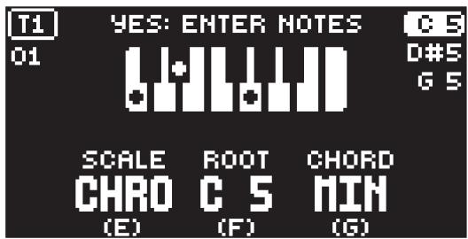
SCALE sets the tracks scale. This is done by limiting which keys are playable on the Digitone keyboard and from external MIDI devices that sends on the Digitone's AUTO channel. For a list of all selectable keyboard scales, please see "APPENDIX D: KEYBOARD SCALES" on page 100.
ROOT sets the root note for the chosen scale.
CHORD adds a three-note chord based on the SCALE and ROOT settings when you press a key on the Digitone keyboard. (OFF, ON) If you set SCALE to CHROMATIC you have a selection of different chords to choose from. (MAJ, MIN, 7TH, MIN7, MAJ7, DIM, DIM7)

- If you press [NOTE] when you are in GRID RECORDING mode you exit the GRID RECORDING mode.
- You can copy the settings in the TRACK NOTE menu and paste it to another track. In the TRACK NOTE menu, press [FUNC] + [RECORD] to copy the parameter settings. Change track and open TRACK NOTE menu, and then press [FUNC] + [STOP] to paste the settings.
10.5 VOICE MENU
Press [VOICE] 📋 to open the VOICE menu, where you handle the allocation of the Digitone's eight voices. In this menu, you can also make the settings for unison and voice stealing. Press [T1-4] key to select which track to edit. At the top left of the screen, you can see what track is selected. Use the DATA ENTRY knobs to change the settings. Press [NO] to exit the menu. The voice settings are stored in the active pattern. The dot next to track T2 denotes that the track is set to a monophonic mode in the PLAY MODE parameter. For more information, please see "9.5.6 PLAY MODE" on page 29.

VOICE STEALING The Digitone has eight voice polyphony. VOICE STEALING sets the rules for how voices are stolen (which voice is taken when you play a new note) when you use more than eight voices at the same time. Press [LEFT]/[RIGHT] to select voice stealing mode.
CYCLE The first played note is stolen first.
TRACK Track priority. Notes played on track 1 has priority over notes played on track 2, 3, and 4. Track 2 notes over track 3, 4 Track 3 notes over track 4.
LO Lowest note is stolen first
HI Highest note is stolen first.
REUSE Selects if the same note played twice should reuse the same voice, or cycle to use another free voice.
ON Reuses the same voice. Useful for staccato effects and drums.
OFF Cycles to use another voice. Good for piano-like sounds and pads.
LOCKED VOICES Sets the number of voices (1–8) you want to lock to a specific track. A locked voice cannot be used or stolen by another track. If you lock voices to a track, the track cannot use more voices than the ones that are locked to it. The first number shows the number of locked voices to the track. The number in brackets shows how many unlocked voices that remain. If you set the parameter to D (dynamic) it will use any available voices to play its Sound.

How many voices that are used to play a Sound is also affected by the PLAY MODE setting in the SOUND SETUP menu. For more information, please see “9.5.6 PLAY MODE” on page 29.
UNISON Gives the possibility to add several voices to play the same note. The parameter sets the number of voices that plays for each note. If unison is not possible due to locked voices on other tracks, this parameter is greyed out and unavailable.

[FUNC] + [VOICE] toggles unison on/off. [VOICE] blinks if unison is not possible due to locked voices on other tracks.
UNISON SPREAD Adds pan and detune to the unison voices.
LAYER Makes it possible to trig two or more tracks with the same note from the sequencer or the keyboard. For example, if you on track 1 set LAYER to affect track 2 then every note you play on track 1 also plays on track 2, effectively playing two Sounds at the same time. Tracks that are layered to the active track have filled squares in the parameter representation on the screen.

You can copy the settings in the VOICE menu and paste it to another pattern. In the VOICE menu, press [FUNC] + [RECORD] to copy the parameter settings. Change pattern and open VOICE menu, and then press [FUNC] + [STOP] to paste the settings.
10.6 MICRO TIMING MENU
Here you can add micro timing to a note trig, moving it ahead or behind the beat. You can customize the micro timing on any of the sequencer steps on both synth and MIDI tracks. In GRID RECORDING mode, press and hold one or several [TRIG] keys and then press [LEFT]/[RIGHT] to access the pop-up Micro timing menu that shows the time offset for the chosen sequencer step(s) on the active track. To exit the micro timing menu, release the [TRIG] key(s). The micro timing settings are stored in the active pattern.

MICRO TIMING Press [LEFT]/[RIGHT] keys to adjust the time offset.
10.7 METRONOME MENU
The METRONOME menu controls the internal metronome of the Digitone. Press [FUNCTION] + [PTN] to open the METRONOME menu. Use the DATA ENTRY knobs to change the settings.

ACTIVE activates/deactivates the metronome. You can also press [FUNC] + [PTN] and hold for a second to toggle the metronome on and off when you are not in the METRONOME menu.
TIME SIG. controls the note and beat measure of the metronome time signature.
PREROLL BARS controls for how many bars the metronome sounds before the sequencer starts playing. This setting is only relevant when you are in LIVE RECORDING mode.
VOL. controls the volume of the click.
10.8 SCALE MENU
You can set the length and timing of the pattern and tracks in this menu. The SCALE menu has two modes. In LENGTH PER PATTERN mode all tracks share the same length. In LENGTH PER TRACK mode, each track can have different lengths. Press [FUNC] + [PAGE] to access the SCALE menu. Press [FUNC] + [YES] to toggle between the two SCALE modes. Use the DATA ENTRY knobs to adjust the settings.
10.8.1 LENGTH PER PATTERN MODE
In this mode, all tracks of the pattern share the same length and time signature.

LENGTH controls the step length of the pattern. The leftmost number displays the number of steps in the pattern. The total length, displayed by the second number, determines the maximum number of steps available in the pattern. If you use 17 steps or more in a pattern, the [PAGE] key is (while in GRID RECORDING mode) used to toggle between the different pattern pages.
SCALE controls the speed of pattern playback in multiples of the current tempo. It offers seven possible settings, 1/8X, 1/4X, 1/2X, 3/4X, 1X, 3/2X and 2X. A setting of 1/8X plays back the pattern at one-eighth of the set tempo. 3/4X plays the pattern back at three-quarters of the tempo; 3/2X plays back the pattern twice as fast as the 3/4X setting. 2X makes the pattern play at twice the BPM.
When you extend the length of a pattern, its trigs copies automatically over to the new steps. If a pattern consists of for example two pages and the pattern length is increased to four pages, the two additional pattern pages are then copies of the first two pattern pages.
Press the [PAGE] key to change the total length of the pattern quickly. Press the [TRIG] keys to change the number of steps of the pattern quickly.
A 2X scale setting is useful for increasing the base resolution of the step sequencer to 32nd notes. A 3/4X setting is useful when Digitone is playing alongside other instruments set to the same BPM, and you want Digitone to play triplets.
10.8.2 LENGTH PER TRACK MODE
In this mode, you can assign individual length and scale to the tracks of the pattern. Press [FUNC] + [YES] to switch between the two scale modes. In LENGTH PER TRACK mode, two columns exist, TRACK and PATTERN.

The TRACK column sets the step length and scale of the track. The settings only affects the active track. Press the [TRK] keys to select the track whose scale settings you wish to edit.
The PATTERN column sets the master change length and the master length of the pattern.
LENGTH controls the step length of the track. The leftmost number displays the number of steps of the track. The total length, displayed by the second number, determines the maximum number of steps available for the track. If you use 17 steps or more in a track, the [PAGE] key is (while in GRID RECORDING mode) used to toggle between the different pattern pages.
SCALE controls the speed of track playback in multiples of the current tempo. It offers seven possible settings, 1/8X, 1/4X, 1/2X, 3/4X, 1X, 3/2X and 2X. A setting of 1/8X plays back the track at one-eighth of the set tempo. 3/4X plays the track back at three-quarters of the tempo; 3/2X plays back the track twice as fast as the 3/4X setting. 2X makes the track play at twice the BPM.
CH.LEN (Change Length) controls for how long the active pattern plays before a cued or chained pattern begins to play. This setting is important when, for example, you set M.LEN to INF. If you do not make any CH.LEN setting, the pattern plays infinitely, and the next pattern is thus not cued. By default a cued pattern change happens at the end of the pattern (CH.LEN set to OFF).
M.LEN (Master Length) controls the number of steps the pattern plays before all tracks restart. An INF setting makes the tracks of the pattern loop infinitely, without ever being restarted. Note that this setting also affects for how long the active pattern plays before a chained pattern starts playing. The CH.LEN parameter overrides this if its parameter value is less than the M.LEN value.

In the SCALE menu, you can press [FUNC] + [UP]/[DOWN] to set the TRACK LENGTH in increments from 2/16 to 64/64.
10.9 SEQUENCER FEATURES
10.9.1 PARAMETER LOCKS
Parameter locks make it possible to set every trig to have its unique parameter values. The note trigs of a synth track can, for example, have different pitch, amp or filter settings. It is possible to parameter lock the parameters found on the PARAMETER pages, and you can apply parameter locks to all types of tracks. For a complete overview of all parameters on the PARAMETER pages, please see “11. SYNTH TRACK PARAMETERS” on page 46, and “12. MIDI TRACK PARAMETERS” on page 56.
Adding parameter locks in GRID RECORDING mode.
- Press [RECORD] to enter GRID RECORDING mode.
- Press [TRIG] to add a Note trig or [FUNC] + [TRIG] key to add a Lock trig and to where you want to perform a parameter lock.
- Press and hold the [TRIG] key(s) of previously placed trig(s) (note trig or a lock trig).
- Turn the DATA ENTRY knobs that control the parameter you want to lock, and set it to the desired value. The graphics become inverted for the locked parameter, and the locked parameter value is displayed. The [TRIG] key of the locked trig blinks red (for note trigs) or yellow (for lock trigs) to indicate the trig now contains a parameter lock.
Press and hold [TRIG], and then press the DATA ENTRY knob of the locked parameter if you wish to remove a single parameter lock. You can erase all parameter locks from a trig if you remove the note trig and then enter it again.
Adding parameter locks in LIVE RECORDING mode.
- Press and hold [RECORD], then press [PLAY] to enter LIVE RECORDING mode.
- Turn a DATA ENTRY knob, or play the [TRIG] keys in KEYBOARD mode, to add parameter locks to the active track. Note trigs are placed, and parameter locked accordingly, and it also places lock trigs that contains the parameter locks on the sequencer steps that do not already have any trigs.
Press [NO] + one (or several) of the [TRACK] keys to erase a sequence of recorded trigs on a specific track (or on several tracks) in time with the sequencer. This procedure erases the trigs on all steps reached by the sequencer on the corresponding tracks.
You can also remove specific parameter locks on a track in real time. In LIVE RECORDING mode, press and hold [NO] and then press and hold the DATA ENTRY knob corresponding to the parameter that you want to remove.
Adding parameter locks in STEP RECORDING mode.
- Press and hold [RECORD], then press [STOP] to enter STEP RECORDING mode.
- Press and hold a [TRIG] key, and then turn the DATA ENTRY knobs that control the parameter you want to lock, and set it to the desired value. The graphics become inverted for the locked parameter, and the locked parameter value is displayed. The [TRIG] key of a locked trig blinks red (for note trigs) or yellow (for lock trigs) to indicate that the trig contains a parameter lock.

Up to 80 different parameters can be locked in a pattern. A parameter counts as one (1) locked parameter no matter how many trigs that lock it. If for example the cutoff parameter of the filter is locked on every sequencer step, there are still 79 other parameters that can be locked.
10.9.2 SOUND LOCKS
You can change a tracks Sound to another Sound from the Sound pool on any individual sequencer step. These Sound locks are an immensely useful feature for adding variations to a track. Press and hold a note trig and turn the LEVEL/DATA knob to open the Sound pool list. Use the LEVEL/DATA knob to scroll through the list. Select the Sound you want to assign to the note trig and then release the [TRIG] key. The [TRIG] key starts to flash to indicate that it contains a Sound lock. Press and hold the [TRIG] key of the note trig to show the assigned Sound. For more information, please see "9.1.1 ADDING SOUNDS TO THE SOUND POOL" on page 27.
10.9.3 TRIG CONDITIONS AND CONDITIONAL LOCKS
Trig conditions are a set of conditional rules that you can apply to any trig, using specific parameter locks called conditional locks. Each rule is a logical condition that determines whether a trig set on a track in the sequencer is triggered or not. If the condition is true, then the trig becomes active and affect the track. If the condition is false, the trig is ignored.
ADDING A CONDITIONAL LOCK
- In GRID RECORDING or STEP RECORDING mode, place a note trig or lock trig on the sequencer step to where you want to apply a conditional lock.
- Press and hold the trig to access the COND (Trig Condition) parameter on the TRIG PARAMETERS page. It temporarily replaces the PROB parameter. For more information, please see "11.2 TRIG PARAMETERS PAGE" on page 46.
- Turn DATA ENTRY knob D to select one of the following trig conditions:
FILL is true (activates the trig) when FILL mode is active.
FILL is true when FILL is false. A trig with this trig condition is active when you are not in FILL mode.
PRE is true if the most recently evaluated trig condition on the same track was true. (PRE and PRE conditions are ignored and not evaluated.)
PRE is true when PRE is false. A trig with this trig condition is active if the most recently evaluated trig condition on the same track was not true. (PRE and PRE conditions are ignored and not evaluated.)
Example 1: Trig 1, 50% = True > Trig 2, = False > Trig 3, = False > Trig 4, PRE = True
Example 2: Trig 1, 50% = False > Trig 2, = True > Trig 3, = True > Trig 4, PRE = False
NEI is true if the most recently evaluated trig condition on the neighbor track was true. (PRE and PRE conditions on the neighbor track are ignored and not evaluated.) The neighbor track is the track before the active track. For example, track 3 is the neighbor track of track 4. NEI and NEI conditional trigs on track 4 evaluate the conditional trigs placed on track 3. The NEI condition is false if no conditional trigs exist on the neighbor track.
NEI is true when NEI is false. A trig with this trig condition is active if the most recently evaluated trig condition on the neighbor track was not true. (PRE and PRE conditions on the neighbor track are ignored and not evaluated.)
1ST is true the first time the pattern plays (when looped).
1ST is true when 1ST is false. A trig with this trig condition is always active apart from the first time the pattern plays (when looped).
X% is a probability condition. There is an X% chance that the trig will be active.
A:B A sets how many times the pattern (or track, if the track length is shorter than the pattern length) plays before the trig condition is true. B sets how many times the pattern (or track, if the track length is shorter than the pattern length) plays before the count is reset and starts over again. This cycle then repeats until you stop the sequencer.
For example:
With the setting 1:2, the trig condition is true the first time the pattern plays and then the third, the fifth, and so on.
With the setting 2:2, the trig condition is true the second time the pattern plays and then the fourth, the sixth, and so on.
With the setting 2:4, the trig condition is true the second time the pattern plays and then the sixth, the tenth, and so on.
With the setting 4:7 the trig condition is true the fourth time the pattern plays and then the eleventh, the eighteenth, and so on.

- The sequencer needs to be in FILL mode to activate the conditional lock called FILL. For more information, please see "10.9.4 FILL MODE" on page 41.
- Conditional parameter locks are a great way to add variety to a pattern. To set up a grid of mutually exclusive or conclusive note trigs across any of the synth tracks, and throwing some probability locks in there as well (perhaps, in turn, also sporting an array of logically conditioned trigs), is a neat way to make the most minimal of compositions come alive with randomness.
- Note that random or arbitrary variety is not the only way of using conditional trigs. They may also be used, for example, to have two different melodic or percussive sequences on the same track, one of which is activated only when FILL mode is active.
10.9.4 FILL MODE
FILL mode can be used to create a temporary variation, such as a drum fill, in your pattern.
Press [YES] + [PAGE] to cue FILL mode for one pattern cycle. All
Press and hold [PAGE] + [YES], and then release [PAGE] before you release [YES] to latch FILL mode. Press [PAGE] again to unlatch FILL mode.
10.10.5 SWING
Adjust the swing setting of the pattern, to employ a propulsive, rhythmic groove. Press [TEMPO] to access this menu.

Turn DATA ENTRY knob E to set the SWING ratio to 51-80%. The default setting is equal spacing, 50%.
10.9.6 COPY, PASTE AND CLEAR OPERATIONS
Patterns, tracks, track pages, and trigs can be copied, pasted and cleared.
You can copy the active pattern to another location in the same bank or another bank. You can not be in GRID RECORDING mode if you want to perform a pattern copy operation. Copy the pattern by pressing [FUNC] + [RECORD]. Select another pattern, and then press [FUNC] + [STOP] to paste the copied pattern to this location. Press [FUNC] + [PLAY] to clear all the trigs in the current pattern.
Individual sequencer tracks can be copied, pasted and cleared in the same way as patterns. GRID RE-CORDING mode must be active to perform these operations.
A single track page may also be copied, pasted and cleared. It is similar to copying/pasting/clearing a track, but only affects the active track page. Select the track page of choice by pressing the [PAGE] key. Copy by pressing [PAGE] + [RECORD]. Select a new track page and press [PAGE] + [STOP] to paste. Press [PAGE] + [PLAY] to clear the active track page.
Trigs, complete with all parameter lock settings, can also be copied, pasted and cleared. GRID RECORDING mode needs to be active to access this functionality. Press and hold a trig and press [RECORD] to perform the copy operation. Paste by holding another [TRIG] key and pressing [STOP]. It is also possible to copy more than one trig. Press and hold the trigs you wish to copy, and then press [RECORD]. Press and hold the [TRIG] key to where you want to paste, and then press [STOP] to paste the copied sequence of trigs. When pasting, the copied trigs are placed in the same relation to each other as they had when they were copied. The destination trig acts as the starting point for the sequence of copied trigs. Clear trig locks by holding one or more trigs and press [PLAY].
You can undo any paste, and clear operation by repeating the key presses.

It is possible to copy, clear and paste one or several patterns without leaving the active pattern. To copy, press and hold [PTN] + [TRIG] key to select the pattern you wish to copy. Then press [RECORD]. Let go of the [TRIG] key and then press and hold the [TRIG] key(s) to where you want to paste the pattern. Finally, press and hold [STOP] until the count down finishes to paste the pattern(s). To clear, press and hold [PTN] + [TRIG] key(s) to select the pattern(s) you wish to clear. Then press and hold [PLAY] to clear the pattern(s).
10.9.7 TEMPORARY SAVE AND RELOAD PATTERN COMMANDS
Patterns can instantly be saved to a temporary memory space and then reloaded again from this space.
- To perform a temporary save of the active pattern, press [FUNC] + [YES]. This is useful when you want to create a restore point when live tweaking, but without permanently save your changes.
- To perform a temporary reload of the active pattern, press [FUNC] + [NO]. It then reloads the pattern from when you last used the temporary save command. If you have not done any temporary save, then the pattern reloads from the permanently saved state.

The TEMPORARY SAVE PATTERN and TEMPORARY RELOAD PATTERN commands are great when improvising live. Any changes made to the active pattern, like adding bass line notes or using CONTROL ALL, can immediately be undone. The temporary saves and reloads do not affect the pattern in a permanent way.

The TEMPORARY SAVE PATTERN command does not save the pattern permanently, and any changes are lost if you load another project. If you wish to save your changes permanently, you should use SAVE TO PROJ in the PATTERN MENU. For more information, please see “14.3 PATTERN” on page 66.
10.9.8 DIRECT TRACK TRANSPOSE
-
Press and hold [T1-4] key and then press [UP]/[DOWN] to initiate Direct track transpose. Only the selected track is transposed.
-
While still holding [T1-4], press [UP]/[DOWN] to transpose the track by semitones. You can see the amount of transpose at the top of the screen. You can also see (and set) the track transpose value on the KEYBOARD SETUP menu. For more information, please see "8.5.2 KEYBOARD SETUP MENU" on page 24.
- Release [T1-4] for the transpose to take effect.
10.9.9 DIRECT PATTERN TRANSPOSE
- Press [PTN] key and then press [UP]/[DOWN] to initiate Direct pattern transpose. All the tracks in the pattern, including the MIDI tracks, are transposed.
- While still holding [PTN], press [UP]/[DOWN] to transpose the patterns tracks by semitones. You can see the amount of transpose at the top right of the screen.
- Release [PTN] for the transpose to take effect.
10.10 CHAINS
Chains are sequences that consist of more than one pattern. You can use chains to preselect and automate in what order you want your patterns to play.

You can create one chain and it can contain any pattern in bank A–H. The chain can consist of up to 64 patterns.
10.10.1 CREATING A CHAIN
- Press [BANK] + [TRIG 9-16] key to select bank.
- Press and hold [PTN] and then press a [TRIG 1-16] key to select the first pattern in the chain.
- Release the [PTN] key and then press [TRIG 1-16] keys in the same order as you want the chained patterns to play. Keep a previous [TRIG] key pressed while you press the next one, the one after that and so on. You can press the same [TRIG] key again if you wish to add the pattern multiple times in a row. If you want to add a pattern from another bank, press [BANK] + [TRIG 9-16] to select bank, and then press [TRIG 1-16] to select pattern.
- Press [PLAY] to start the sequencer and play the chain. The chain will be looped once the final pattern of the chain has played.

Please note that the chain will be lost when you create a new chain or when you select a new bank/pattern. Also, chains cannot be saved and are lost when you switch the Digitone off.

- It is possible to create chains while the sequencer is running.
- You can also use MIDI program change messages from an external device to change patterns on the Digitone. For more information, please see "14.5.1 SYNC" on page 71..
10.11 SONG MODE
A song is an arrangement of patterns set up to play in sequence. Each row in the SONG mode arrangement can have separate settings for pattern, row repeat, row length, tempo, and mute. A song can be up to 99 rows in length, and each project can contain up to 16 songs.
10.11.1 THE SONG EDIT SCREEN
Press [SONG MODE] 🎨 and then press [YES] to enter SONG mode. The song selected will be the one that was last played or edited. Press [SONG MODE] and then press [RIGHT] to open the SONG EDIT screen. Use the [ARROW] keys to navigate the song rows and columns, highlighting the parameter you wish to edit, and then use LEVEL/DATA or any DATA ENTRY knob to edit the selected function.

- SONG ROW (Range 01–99)
- LABEL lets you select a keyword for the row. The keyword is related to song structure, e.g., Verse, Chorus, and Fill. It can also be the name of the pattern.
- PTN lets you select the pattern to be played on the row. Press [FUNC] while turning the knob to change banks quickly.
- ROW REPEAT The number of times the row will repeat, considering the ROW LENGTH setting. (Range: 1 (OFF)–32).
- ROW LENGTH (measured in sequencer steps). This setting defines how many steps the sequencer plays from the selected pattern. The default value is the same as the pattern length. (Range: 2–1024, the last 25 values are written as K00–K24)
- ROW TEMPO Here, you set the row's BPM per row. You can also choose to have one BPM for the whole song. By default, the row inherits the BPM and swing set in the pattern selected for the row. Press [TEMPO] to open the TEMPO menu for the currently selected row's pattern. Here you can also set the swing. You can also press [YES] while highlighting the BPM parameter to open the TEMPO menu. Selecting song tempo on any row overrides all the previously set row and pattern tempos. The swing settings are always set per row.
- SONG POINTER Shows the current time and position of the playhead in the song arrangement.
- ROW MUTE lets you mute the tracks of the pattern on the selected row. Highlight and press [YES] to edit. A mute icon is displayed in the rows that have tracks that are muted. Use the [TRIG] keys to mute and unmute the tracks. When selecting a pattern for the row, the row's mute state initially reflects the pattern's mute state
- END row. This row is always added at the end of a song and determines what will happen when the song has played the last song row. By default, it is set to LOOP the song from the beginning and play it again, but it can also be set to STOP the song.
- The currently selected row is highlighted between dotted lines. Use [UP] and [DOWN] to select row.
- PLAYHEAD position shows the row currently playing (or set to play if the sequencer is stopped).
12.SONG SLOT and SONG NAME.
10.11.2 CREATING AND EDITING A SONG
- Press [SONG MODE] and then press [YES] to enter SONG mode. The [SONG MODE] key lights up yellow when SONG mode is active. The song selected will be the one that was last played or edited. If you wish to edit another song, press [SONG MODE] + [DOWN] to open the LOAD SONG screen, highlight the song you want to edit, and then press [YES].
- Press [SONG MODE] + [RIGHT] to open the SONG EDIT screen.
- If you selected an empty song slot, you are presented with a screen where you can choose:
INSERT ROW Inserts the first row in the song. Press [FUNC] + [DOWN] to insert a row.
CREATE ROWS FROM CHAIN Creates a song based on a chain. Press [YES] and then select to create rows from a previously created chain or to create a new chain by selecting patterns using the [BANK] and [PTN] + [TRIG 1-16] keys. Then press [YES] to create a song based on the chain and open the SONG EDIT screen.
- Press [FUNC] + [DOWN] if you want to add a new row to the song arrangement. The new row is added below the currently selected row and is a copy of the selected row. Press [FUNC] + [UP] to remove the selected row from the song arrangement.
-
Use the [ARROW] keys to navigate the song rows and columns, highlighting the item you wish to edit. For more information about editing the functions in SONG mode, please see "10.11.1 THE SONG EDIT SCREEN" on page 43.
-
To rename the song, navigate to SETTINGS > SONG > RENAME, and then edit the song name.
-
Press [NO] to exit the SONG EDIT screen.

• [FUNC] + [RECORD] copies the selected row.
[FUNC] + [STOP] pastes a previously copied row to the selected row.
[FUNC] + [PLAY] resets the selected row to the pattern's default BPM, length, and mute state settings.
[FUNC] + [UP] deletes the selected row.
- Please note that there is always a row called END at the song's end. This row can be set to either STOP the song or LOOP it from the beginning and play it again.
- On the SONG EDIT screen, you can select a song row number and then press YES to move the playhead to this row.
10.11.3 PLAYING A SONG
-
Press [SONG MODE] and then press [YES] to confirm to enter SONG mode. The [SONG MODE] key lights up yellow when SONG mode is active. The song selected will be the one that was last played or edited. If you wish to play another song, press [SONG MODE] + [DOWN] to open the LOAD SONG screen, highlight the song you want to edit, and then press [YES].
-
Press [PLAY] to play the selected song. At the top of the screen, you see the song number, the row currently playing, the total number of rows in the song, the row's LABEL, and finally the patterns bank/number. This part of the screen is also used as a progress bar to show how far in the row the song pointer has progressed.

-
Press [STOP] to stop the playback. You can then press [PLAY] to continue to play the song from the current playhead position. Press [STOP] twice to move the playhead to the song's beginning.
-
Press [SONG MODE] and then press [YES] to confirm to exit SONG mode.

- Press [SONG MODE] + [UP] to open the SONG menu.
- Press [SONG MODE] + [DOWN] to open the LOAD SONG screen.
- Press [SONG MODE] + [LEFT] (when in SONG mode) to loop the currently playing row. Press [SONG MODE] + [LEFT] again to stop looping the row and return to normal song playback.
- Press [SONG MODE] + [RIGHT] (when in SONG mode) to open the SONG EDIT screen. You can also press [SONG MODE] twice to open the SONG EDIT screen.
- Press [SONG MODE] + [YES] to enter/exit SONG mode.
- You can also use the [BANK] and [PTN] + [TRIG 1-16] keys to select a pattern to exit SONG mode and return to regular pattern play.

The songs are automatically saved as they are created and edited. However, you must save the project if you wish to keep the songs before switching to another project.
11. SYNTH TRACK PARAMETERS
Here follows a description of all of the parameters that are available on the synth tracks PARAMETER pages. The parameters on the TRIG page are saved with the pattern, and not with the sound. You can lock the synth track parameters to other settings on any step of the pattern by first pressing and holding a [TRIG] key, then changing the parameters' settings with the DATA ENTRY knobs. For more information, please see "10.9.1 PARAMETER LOCKS" on page 39.
11.1 EDITING THE SYNTH TRACK PARAMETERS
There are six PARAMETER page groups for the synth tracks. Press the [PARAMETER] keys to access the synth tracks PARAMETER pages. The SYN2, FLTR, AMP and LFO parameter groups has two pages To access page one, press the [PARAMETER] key once. To access page two, press the [PARAMETER] key twice. Use the DATA ENTRY knobs A-H to change the parameters. Press and hold a [PARAMETER] key to see the values for all parameters on that page.

- You can also randomize the parameter settings on a specific PARAMETER page on a Synth track. Press [PARAMETER] key + [YES] to randomize all parameters on that page. Every time you press this key combination, the parameters randomize in a new way.
- Press [PARAMETER] key + [NO] to reset the PARAMETER page to its last saved state.
- Press and hold a [PARAMETER] key to see all the parameter settings on the PARAMETER page.
11.2 TRIG PARAMETERS PAGE
Here you find the parameters for the note trigs. Use the DATA ENTRY knobs to change the settings. The settings on the TRIG PARAMETERS page is not saved with the Sound. They are saved with the pattern.
Press [TRIG PARAMETERS] to access this parameter page.
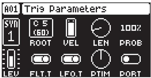
11.2.1 ROOT
Root sets the default note value that the note trigs placed in GRID RECORDING mode have. If you change the root note and have additional notes added on the same trig, then the additional notes are offset and transposed accordingly. For more information, please see “10.2.3 GRID RECORDING USING TRACK NOTE METHOD” on page 33. (C0–G10)
11.2.2 VEL
Trig Velocity controls the velocity of the notes the MIDI track sends out. A setting of 0 equals a NOTE OFF command. (1–127)
11.2.3 LEN
Trig Length sets the duration of the notes. When a note has finished playing a NOTE OFF command is sent. The INF setting equals infinite note length. (0.125–128, INF)
11.2.4 PROB
TRIG PROBABILITY sets the probability that the trigs on the track plays or not. The probability outcome is re-evaluated every time a trig is set to play. The default setting is 100%, meaning that all the trigs on the track plays every time. (0%–100%)
This parameter changes temporarily to display and control COND (Trig Condition) when you add a conditional lock. For more information, please see “10.9.3 TRIG CONDITIONS AND CONDITIONAL LOCKS” on page 40.

If you have placed a conditional lock on a trig in the sequencer, the trig condition overrides the Trig Probability setting. For example, if you set PROB to 70% and a FILL trig condition on a trig, that trig will only (and always) play when the Digitone is in FILL mode. For more information, please see “10.9.3 TRIG CONDITIONS AND CONDITIONAL LOCKS” on page 40.
11.2.5 FLT.T
Filter Trig controls if the filter envelope is triggered or not. (ON, OFF)
11.2.6 LFO.T
LFO Trig controls if the LFO is triggered or not. (ON, OFF)
11.2.7 PTIM
Portamento Time sets the time for the portamento (1–127)
11.2.8 PORT
Portamento turns the portamento on/off (ON, OFF)
For more information, please see "9.5.5 PORTAMENTO" on page 29.
11.3 SYN1 PAGE 1
The parameters on the SYN1 page 1 control various aspects of the FM synthesis. You can find more information about the Digitone FM synthesis in “APPENDIX A: THE DIGITONE FM SYNTHESIS” on page 89 and “A.7 SYN1 PAGE 1 PARAMETERS OVERVIEW” on page 93.
Press [SYN1] once to access this parameter page.

11.3.1 ALGO
Algorithm selects the set structure of how the four operators are connected to each other. (1–8) For more information, please see “A.3 ALGORITHMS” on page 90.
11.3.2 RATIO C
Sets the frequency ratio for operator C. (0.25–16.0) For more information, please see “A.4 FM RATIOS” on page 90.
11.3.3 RATIO A
Sets the frequency ratio for operator A. (0.25–16.0) For more information, please see “A.4 FM RATIOS” on page 90.
11.3.4 RATIO B
Sets the frequency ratio for operator B1 and B2. The minimum value for B1 and B2 is .25. As you turn the encoder, B2 increases until it reaches the max (16). It then starts over from .25 and B1 increases to the next value (0.5). This revolving behavior continues until both operators reach the maximum value. This parameter behavior is similar to the movement of the hands on a watch. (0.25–16.0) For more information, please see “A.4 FM RATIOS” on page 90.
11.3.5 HARM
Harmonics controls waveform of the operators, C, A, and B1. The parameter is bipolar. Negative parameter values change the harmonics of operator C, while positive parameter values change the harmonics of operators A and B1. (-26.00–26.00) For more information, please see “A.6 HARMONICS” on page 92.
11.3.6 DTUN
Detune offsets the ratio of operator A and B2. Up until a parameter value of around 64, the offset is very slight to achieve subtle movement and drifting. Above 64 the operators start to detune more heavily. 0.00–127.00)
11.3.7 FDBK
Feedback sets the amount of self modulation of the operator that has feedback. This operator is shown in the algorithm on the screen with a feedback loop in its upper left corner. (0.00–120.00). For more information, please see “A.2 THE OPERATORS” on page 89.
11.3.8 MIX
Each algorithm has two carrier outputs (X and Y) that come from two different operators depending on what algorithm you chose. Use the MIX parameter to mix between these outputs so that you can cross-fade between two separate timbres. (-64–63). For more information, please see “A.3 ALGORITHMS” on page 90.
11.4 SYN1 PAGE 2
The parameters on the SYN1 page 2 controls the operators ratio offsets.
Press [SYN1] twice to access this parameter page.

11.4.1 RATIO OFFSET C, A, B1, B2
Adds offsets to the ratios of each of the four operators.
11.5 SYN 2 PAGE 1
The parameters on the SYN2 pages control various aspects of the FM synthesis, mainly the amount of frequency modulation together with the operator envelopes and their behavior.
The FM engine has two operator envelopes. One is for operator group A, and one is for group B (B1 and B2). The envelopes are essentially expanded AD (Attack Decay) envelopes, but with an added adjustable end level (the amplitude level the sound reaches at the end of the decay stage). For more information, please see “A.5 THE OPERATOR ENVELOPES” on page 91.
Press [SYN2] once to access this parameter page.

11.5.1 ATK A
Attack Time sets the length of the attack phase of the modulation envelope for operator A. (0–127)
11.5.2 DEC A
Decay Time sets the length of the decay phase of the modulation envelope for operator A. (0–127)
11.5.3 END A
End Level sets the end level of the modulation envelope for operator A. (0–127)
11.5.4 LEV A
Level sets the modulation amount from operator A. (0–127)
11.5.5 ATK B
Attack Time sets the length of the attack phase of the modulation envelope for operator group B (B1 and B2). (0–127)
11.5.6 DEC B
Decay Time sets the length of the decay phase of the modulation envelope for operator group B (B1 and B2). (0–127)
11.5.7 END B
End Level sets the end level of the modulation envelope for operator group B (B1 and B2). (0–127)
11.5.8 LEV B
Level sets the modulation amount from operator group B (B1 and B2). (0–127)
The LEVEL parameter for B is macro mapped to both operator B1 and B2 and control their modulation amount as per this graph:


If you wish to use frequency modulation, it is important that you turn the LEV parameters up, since they set the amount of frequency modulation in the FM engine.
11.6 SYN2 PAGE 2
The parameters on the SYN2 pages control various aspects of the FM synthesis, mainly the amount of frequency modulation together with the operator envelopes and their behavior.
Press [SYN2] twice to access this parameter page.

11.6.1 ADEL
Envelope delay sets the time before attack phase of the modulation envelope for operator A starts. (0–127)

11.6.2 ATRG
Envelope trig sets the trig behavior of the operator envelopes. The envelopes can be either triggered or gated - making it either an ADE (Attack Decay End) or an ASDE (Attack Sustain Decay End) envelope. The sustain phase does not have an adjustable envelope level. It is instead the LEV parameter that sets the sustain level. The note length defines the length of the sustain phase.
Trigged (ATRG/BTRG ON)

Gated (ATRG/BTRG OFF)

11.6.3 ARST
Envelope reset sets if the envelopes should reset or not when they are retrigged.
Reset on (ARST/BRST ON)

Reset off (ARST/BRST OFF)

11.6.4 PHRT
Phase reset sets if the operators phase are reset to start at 0 or not when they are triggered.
OFF do not reset any operators
ALL resets all operators
C resets operator C
A+B resets operator A, B1, and B2
A+B2 resets operator A and B2
11.6.5 BDEL
Same as ADEL but for operator group B (B1 and B2).
11.6.6 BTRG
Same as ATRG but for operator group B (B1 and B2).
11.6.7 BRST
Same as ARST but for operator group B (B1 and B2).
11.7 FLTR PAGE 1
On FILTER page 1, you find all parameters that control the Multimode filter and its associated envelope. The Multimode filter and the Base-Width filter are placed in series with the Base-Width filter before the Multimode filter.
Press [FLTR] once to access this parameter page.

11.7.1 ATK
Attack Time sets the length of the attack phase of the filter envelope. (0–127)
11.7.2 DEC
Decay Time sets the length of the decay phase of the filter envelope. (0–127)
11.7.3 SUS
Sustain Level sets the sustain level of the filter envelope. (0–127)
11.7.4 REL
Release Time sets the length of the release phase of the filter envelope. (0–126, INF)
11.7.5 FREQ
Frequency sets the cutoff frequency of the multimode filter. (0.00–127.00)
11.7.6 RESO
Resonance sets the resonance behavior of the filter. Resonance introduces a peak in the spectrum at the cutoff frequency. (0.00–127.00)
11.7.7 TYPE
Filter Type selects the type of filter. (OFF, 2-pole (12 dB) Lowpass, 2-pole (12 dB) Highpass, 4 pole (24 dB) Lowpass)
11.7.8 ENV
Env. Depth sets the amount of cutoff frequency modulation from the filter envelope. The parameter is bipolar, both negative and positive modulation depths are available. Range (-64.00–63.00)
11.8 FLTR PAGE 2
On FILTER page 2, you find the parameters that control the 1-pole (6 dB) Base-Width filter. The Base-Width filter and the Multimode filter are placed in series with the Base-Width filter before the Multimode filter.
Press [FLTR] twice to access this parameter page.

The base-width filter is basically a Highpass filter and a Lowpass filter connected in series. The filters BASE and WIDTH parameters define the base-width filters frequency range.
Examples of how the BASE and WIDTH parameters affect the filter frequency range:

FREQUENCY

FREQUENCY

FREQUENCY

- With BASE set to 0, the filter functions as a low pass filter with WIDTH adjusting the frequency range.
- With WIDTH set to 127, the filter functions as a high pass filter with BASE adjusting the frequency range.
- With BASE set to 0 and WIDTH set to 127 the filter does not affect the sound.
11.8.1 DEL
Envelope delay sets the time before the attack phase of the filter envelope starts. This parameter is part of the filter envelope that controls the multimode filter. You can also press and hold [FUNC] and then turn DATA ENTRY knob A to quickly access this parameter from FILTER page 1.
11.8.2 BASE
Sets the base frequency of the filter. (0–127)
11.8.3 WIDTH
Sets the frequency width above the base frequency. (0–127)
11.9 AMP PAGE 1
The AMP page 1 controls parameters for the amplitude envelope, overdrive, tone, panning and volume. Press [AMP] once to access this parameter page.

11.9.1 ATK
Attack Time sets the length of the attack phase of the amp envelope. (0–127)
11.9.2 DEC
Decay Time sets the length of the decay phase of the amp envelope. (0–127)
11.9.3 SUS
Sustain Level sets the sustain level of the amp envelope. (0–127)
11.9.4 REL
Release Time sets the length of the release phase of the amp envelope. (0–126, INF)
11.9.5 DRV
Overdrive sets the amount of overdrive and clipping distortion of the signal entering the filter. (0.00–127.00)
11.9.6 PAN
Pan positions the sound in the stereo field. The knob function is bipolar with 0 being the balanced midpoint, L64 sends all sound to the left channel, and R63 sends all sound to the right channel. (L64–R63)
11.9.7 VOL
Volume sets the amount volume of the sound. This parameter is independent of the overall track level. (0.00–127.00)

11.10 AMP PAGE 2
The AMP page 2 controls parameters for the effects sends and amp envelope reset volume.
Press [AMP] twice to access this parameter page.

11.10.1 CHR
Chorus Send sets the amount of sound sent through to the Chorus effect. For more information, please see “13. FX PARAMETERS” on page 60. (OFF, 0.01–127.00)
11.10.2 DEL
Delay Send sets the amount of sound sent through to the Delay effect. For more information, please see "13. FX PARAMETERS" on page 60. (OFF, 0.01–127.00)
11.10.3 REV
Reverb Send sets the amount of sound sent through to the Reverb effect. For more information, please see “13. FX PARAMETERS” on page 60. (OFF, 0.01–127.00)
11.10.4 AENR
Amp envelope reset sets the amp envelope behavior:
ON resets the envelopes for each consecutive trig (default).
OFF does not reset the envelopes for each consecutive trig. It instead lets the envelope cycle complete.
11.11 LFO PAGE 1
The two Low-Frequency Oscillators can be used to modulate the parameters found on the synth tracks SYN1, SYN2, FILTER and AMP pages. Customize the low-frequency oscillators destination, wave, speed, and depth on this page. The parameters LFO page 1 controls LFO 1.
Press [LFO] to access this parameter page.

11.11.1 SPD
Speed sets the speed of the LFO1. Try settings of 8, 16 or 32 to sync the LFO to straight beats. The knob is bipolar. The LFO cycle can be played backward by using negative values. (-64.00–63.00)
11.11.2 MULT
Multiplier multiplies the LFO1 SPD parameter by the set factor either by multiplying the current tempo (BPM settings) or by multiplying a fixed tempo of 120 BPM.
11.11.3 FADE
Fade In/Out makes it possible to fade in/fade out the LFO1 modulation. The knob is bipolar. Positive values give a fade-out, negative values give a fade in. 0 gives no fade in/fade out. (-64–63)
11.11.4 DEST
Destination selects the modulation destination for the LFO1. Preview how the LFO modulation affects the sound by highlighting a destination. Press [YES] to confirm the selection. For more information, please see “APPENDIX C: LFO MODULATION DESTINATIONS” on page 104.
11.11.5 WAVE
Waveform sets the LFO1 waveform. There are seven waveforms: Triangle, Sine, Square, Sawtooth, Exponential, Ramp, and Random.
11.11.6 SPH
Start Phase sets the point within the wave cycle where the LFO1 starts when it is triggered. 0 makes the LFO start at the beginning of a complete wave cycle, 64 makes it start at the center. (0–127)
11.11.7 MODE
Trig Mode sets how the LFO1 acts when triggered by a note
FRE is the default free-running mode. It makes the LFO run continuously, never restarting or stopping even if triggered by a note.
TRG makes the LFO restart when a note is triggered.
HLD makes the LFO run free in the background, but when a note is triggered the LFO output level is latched and held still until the next note is triggered.
ONE The LFO starts when a note is triggered, then runs to the end of the waveform and then stops. This makes the LFO function similar to an envelope.
HLF The LFO starts when a note is triggered, then runs to the middle of the waveform and then stops
11.11.8 DEP
Depth sets the depth and polarity of the LFO1 modulation. Both negative (inverted) and positive modulation depth is possible. A center setting, 0.00, equals no modulation depth. (-64.00–63.00)
11.12 LFO PAGE 2
LFO page 2 page contains the same parameters as LFO page 1, but controls the behavior of LFO 2. Press [LFO] twice to access this parameter page.
LFO waveforms and trig modes.

LFO speed (measured in whole note values) generated by combinations of the SPD and MULT settings.
| MULT | |||||||||||||
| SPD | 1 | 2 | 4 | 8 | 16 | 32 | 64 | 128 | 256 | 512 | 1K | 2K | |
| 1 | 128 | 64 | 32 | 16 | 8 | 4 | 2 | 1 | 1/2 | 1/4 | 1/8 | 1/16 | |
| 2 | 64 | 32 | 16 | 8 | 4 | 2 | 1 | 1/2 | 1/4 | 1/8 | 1/16 | 1/32 | |
| 4 | 32 | 16 | 8 | 4 | 2 | 1 | 1/2 | 1/4 | 1/8 | 1/16 | 1/32 | 1/64 | |
| 8 | 16 | 8 | 4 | 2 | 1 | 1/2 | 1/4 | 1/8 | 1/16 | 1/32 | 1/64 | 1/128 | |
| 16 | 8 | 4 | 2 | 1 | 1/2 | 1/4 | 1/8 | 1/16 | 1/32 | 1/64 | 1/128 | 1/256 | |
| 32 | 4 | 2 | 1 | 1/2 | 1/4 | 1/8 | 1/16 | 1/32 | 1/64 | 1/128 | 1/256 | 1/512 | |
| 64 | 2 | 1 | 1/2 | 1/4 | 1/8 | 1/16 | 1/32 | 1/64 | 1/128 | 1/256 | 1/512 | 1/1024 | |
12. MIDI TRACK PARAMETERS
Here follows a description of the parameters that are on the MIDI tracks PARAMETER pages. The MIDI tracks parameters are saved together with the pattern. You can press and hold a [TRIG] key, and then change the parameters settings with the DATA ENTRY knobs to lock the parameters to other settings on any step of the pattern. For more information, please see “10.9.1 PARAMETER LOCKS” on page 39.
12.1 EDITING THE MIDI TRACK PARAMETERS
There are five PARAMETER pages for the MIDI tracks. Press the [PARAMETER] keys to access the MIDI tracks PARAMETER pages. Use the DATA ENTRY knobs A-H to change the parameters. Press and hold a [PARAMETER] key to see the values for all parameters on that page.
12.2 TRIG PARAMETERS PAGE
Here you find the parameters for the note trigs. Change settings using the DATA ENTRY knobs. These general settings affect note trigs placed in the sequencer.
Press [TRIG PARAMETERS] to access this parameter page.

12.2.1 ROOT
Root sets the default note value that the note trigs placed in GRID RECORDING mode have. If you change the root note and have additional notes added on the same trig, then the additional notes are offset and transposed accordingly. (C0–G10)
12.2.2 VEL
Trig Velocity controls the velocity of the notes the MIDI track sends out. A setting of 0 equals a NOTE OFF command. (1–127)
12.2.3 LEN
Trig Length sets the duration of the notes. When a note has finished playing a NOTE OFF command is sent. The INF setting equals infinite note length. (0.125–128, INF)
11.2.4 PROB
TRIG PROBABILITY sets the probability that the trigs on the track plays or not. The probability outcome is re-evaluated every time a trig is set to play. The default setting is 100%, meaning that all the trigs on the track plays every time. (0%–100%)
This parameter changes temporarily to display and control COND (Trig Condition) when you add a conditional lock. For more information, please see “10.9.3 TRIG CONDITIONS AND CONDITIONAL LOCKS” on page 40.

If you have placed a conditional lock on a trig in the sequencer, the trig condition overrides the Trig Probability setting. For example, if you set PROB to 70% and a FILL trig condition on a trig, that trig will only (and always) play when the Digitone is in FILL mode. For more information, please see “10.9.3 TRIG CONDITIONS AND CONDITIONAL LOCKS” on page 40.
12.2.6 LFO.T
LFO Trig controls if the LFO is triggered or not. (ON, OFF)
12.3 SYN1 PAGE (MIDI SOURCE)
Here you can set the MIDI channel that the MIDI track should use to send data. Bank and program change values are also set here, together with a few standard CC parameters. The default value of the parameters on this page is OFF, meaning they are disabled and do not send out any data. Press and hold [FUNC] and then press the DATA ENTRY knobs to enable them. You can then use the DATA ENTRY knobs to set the
parameter values as usual. Disable the parameters again by repeating the activation procedure.
Press [SYN1] once to access this parameter page.

12.3.1 CHAN
Channel sets the MIDI channel the track sends MIDI data to. If you set this parameter to OFF, it turns the MIDI track off. Please note that this parameter cannot be parameter locked. (OFF, 1–16)
12.3.2 BANK
Bank sends a bank change message on CC 0 MSB. (OFF, 1–128)
12.3.3 SBNK
Sub Bank sends a bank change message on CC 32 LSB. (OFF, 1–128)
12.3.4 PROG
Program Change sends a Program Change message. (OFF, 1–128)
12.3.5 PB
Pitch Bend controls the pitch bend data sent on the MIDI track. (OFF, -128.00–128.00)
12.3.6 AT
Aftertouch controls the aftertouch data sent on the MIDI track. (OFF, 0–127)
12.3.7 MW
Mod Wheel controls the modulation wheel data sent on the MIDI track. (OFF, 0–127)
12.3.8 BC
Breath controller controls the breath control data sent on the MIDI track. (OFF, 0–127)
12.4 SYN2 PAGE (MIDI SOURCE)
SYN2 page contains the same parameters as the SYN1 page. Press [SYN2] to access this parameter page.
12.5 FLTR PAGE (CC VALUE)
Here you can set the values of up to eight assignable CC commands. The default value of the parameters on this page is OFF, meaning they are disabled and do not send out any data. Press and hold [FUNC] and then press the DATA ENTRY knobs to enable them. You can then use the DATA ENTRY knobs to set the parameter values as usual. Disable the parameters again by repeating the enabling procedure.
Press [FLTR] to access this parameter page.

12.5.1 VAL1-VAL8
CC 1–8 Value controls the values that the CC commands send. You specify the CC commands themselves on the AMP (CC SELECT) page. These parameters default value is OFF. Press [FUNC] + DATA ENTRY knobs to activate the parameters and then turn the DATA ENTRY knobs to set a value. (OFF, 0–127)
12.6 AMP PAGE (CC SELECT)
Here you select the eight CC commands whose values you set with the parameters on the FLTR PAGE (CC VALUE) page.
Press [AMP] to access this parameter page.

12.6.1 SEL1-SEL8
CC 1–8 Select specifies the CC commands whose values you control controlled by the parameters on the AMP PAGE 1 (CC VALUE) page. The selectable commands are the standard MIDI Control Change Messages. (1–119)
12.7 LFO PAGE
The Low-Frequency Oscillator can be used to interact with the parameters found on the MIDI tracks' SYN1, and FLTR pages. Customize the low-frequency oscillator behavior, orientation, and depth on this page.
Press [LFO] to access this parameter page.

12.7.1 SPD
Speed sets the speed of the LFO1. Try settings of 8, 16 or 32 to sync the LFO to straight beats. The knob is bipolar. The LFO cycle can be played backward by using negative values. (-64.00–63.00)
12.7.2 MULT
Multiplier multiplies the LFO1 SPD parameter by the set factor either by multiplying the current tempo (BPM settings) or by multiplying a fixed tempo of 120 BPM.
12.7.3 FADE
Fade In/Out makes it possible to fade in/fade out the LFO1 modulation. The knob is bipolar. Positive values give a fade-out, negative values give a fade in. 0 gives no fade in/fade out. (-64–63)
12.7.4 DEST
Destination selects the modulation destination for the LFO1. Preview how the LFO modulation affects the sound by highlighting a destination. Press [YES] to confirm the selection. For more information, please see “APPENDIX C: LFO MODULATION DESTINATIONS” on page 104.
12.7.5 WAVE
Waveform sets the LFO1 waveform. There are seven waveforms: Triangle, Sine, Square, Sawtooth, Exponential, Ramp, and Random.
12.7.6 SPH
Start Phase sets the point within the wave cycle where the LFO1 starts when it is triggered. 0 makes the LFO start at the beginning of a complete wave cycle, 64 makes it start at the center. (0–127)
12.7..7 MODE
Trig Mode sets how the LFO1 acts when triggered by a note
FRE is the default free-running mode. It makes the LFO run continuously, never restarting or stopping even if triggered by a note.
TRG makes the LFO restart when a note is triggered.
HLD makes the LFO run free in the background, but when a note is triggered the LFO output level is latched and held still until the next note is triggered.
ONE The LFO starts when a note is triggered, then runs to the end of the waveform and then stops.
This makes the LFO function similar to an envelope.
HLF The LFO starts when a note is triggered, then runs to the middle of the waveform and then stops
12.7.8 DEP
Depth sets the depth and polarity of the LFO1 modulation. Both negative (inverted) and positive modulation depth is possible. A center setting, 0.00, equals no modulation depth. (-64.00–63.00)
13. FX PARAMETERS
Here follows a description of the parameters on the CHORUS, DELAY, REVERB, and MASTER PARAMETER pages.
13.1 EDITING THE FX PARAMETERS
The Digitone's Chorus, Delay, and Reverb are send effects and are on a pattern level. It means that all the Sounds in a pattern shares the same effect settings but have individual send levels to the effects. You set the Chorus, Delay, and Reverb parameters on their respective PARAMETER page, but their incoming signals are set by the CHR, DEL, and REV send parameters on the AMP page of each synth track. Press [FUNC] + [SYN2] to edit the Chorus. Press [FUNC] + [FLTR] to edit the Delay. Press [FUNC] + [AMP] to edit the Reverb. Use the DATA ENTRY knobs A-H to change the parameters.

The FX parameter settings are stored as part of the pattern. Don't forget to save the pattern and give it a unique name once you have achieved the desired results.
13.2 CHORUS
The chorus can be used to widen sounds, enhance the stereo image or add subtle movement to sounds. Press [FUNC] + [SYN2] to access this parameter page.

13.2.1 DPTH
Depth sets the depth of the LFO modulation of the chorus.
13.2.2 SPD
Speed sets the speed of the LFO modulation of the chorus.
13.2.3 HPF
High-pass filter sets the highpass filtering of the input signal.
13.2.4 WDTH
Width sets the stereo width of the chorus.
13.2.5 DEL
Delay Send sets how much of the wet chorus signal to send through to the delay.
13.2.6 REV
Reverb Send sets how much of the wet chorus signal to send through to the reverb.
13.3 DELAY
The delay send effect takes the input signal, delays it in time and then adds it to the original signal. Press [FUNC] + [FLTR] to access this parameter page.

13.3.1 TIME
Delay Time sets the delay time. The delay time settings are relative to the current BPM and is measured in 128th notes. (1.00–128.00)
| TIME setting | Divide ratio |
| 1 | 1/128 |
| 2 | 1/64 |
| 2.67 | 1/48 (1/32T) |
| 3 | 1/64. |
| 4 | 1/32 |
| 5.33 | 1/24 (1/16T) |
| 6 | 1/32. |
| 8 | 1/16 |
| 10.67 | 1/12 (1/8T) |
| 12 | 1/16. |
| 16 | 1/8 |
| 21.33 | 1/6 (1/4T) |
| 24 | 1/8. |
| 32 | 1/4 |
| 42.67 | 1/3 (1/2T) |
| 48 | 1/4. |
| 64 | 1/2 |
| 96 | 1/2. |
| 128 | 1 |
13.3.2 X
Ping-pong sets the delay signal to alternate across the stereo field. There are two settings:
OFF lets you manually set the position of the delay signal in the stereo field. Use the WID parameter to change the stereo field position.
ON makes the delay signal alternate between left and right pan positions. The WID parameter controls the amount of panning.
13.3.3 WID
Stereo Width sets the delay signal pan width across the stereo field. The knob is bipolar. (-64.00–63.00)
13.3.4 FDBK
Feedback Gain sets the amount of delay output signal to feed back into the input of the delay. With higher parameter settings, infinite and swelling delays are possible. Please be aware that high feedback can lead to a very loud signal. (0–198)
13.3.5 VOL
Mix Volume adjusts the volume of the Delay output signal. (0.00–127.00)
13.3.6 HPF
Feedback HPF sets the cutoff frequency of the delay highpass filter. (0.00–127.00)
13.3.7 LPF
Feedback LPF sets the cutoff frequency of the delay lowpass filter. (0.00–127.00)
13.3.8 REV
Reverb Send sets the amount of Delay output signal to be sent to the Reverb. (0.00–127.00)
13.4 REVERB
The reverb send effect controls the persistence, and ambient characteristics, of the sound reverberations. It can simulate many different sonic locations, from huge spaces to small rooms.
Press [FUNC] + [AMP] to access this parameter page.

13.4.1 PRE
Pre-delay sets the pre-delay time of the Reverb. (0.00–127.00)
13.4.2 DEC
Decay Time sets the length of the decay phase of the reverberated signal, essentially setting the size of the acoustic space. (1–127, INF)
13.4.3 FREQ
FB Shelving Freq sets the shelving filter frequency. Together with the GAIN parameter, it can be used to dampen the reverberated signal above a chosen frequency, making the reverberation sound more prominent or more muffled. (0.00–127.00)
13.4.4 GAIN
FB Shelving Gain affects the damping of the reverberated signal above the shelving frequency set by the FREQ parameter. At max value the treble is included in the reverberations; lowering the value gradually dampens it. (0.00–127.00)
13.4.5 VOL
Mix Volume sets the volume of the Reverb output signal. (0.00–127.00)
13.4.6 HPF
HPF sets the cutoff frequency of the reverb high-pass filter that affects the audio going in to the reverb.. (0.00–127.00)
13.4.7 LPF
LPF sets the cutoff frequency of the reverb low-pass filter that affects the audio going in to the reverb. (0.00–127.00)
13.5 INTERNAL MIXER (MASTER PAGE 1)
The INTERNAL MIXER page is where you can conveniently access the TRACK LEVEL parameter of all the four synth tracks. You also find the master overdrive and pattern volume parameters on this page.
Press [FUNC] + [LFO] to access this parameter page.

13.5.1 MOVD
Master Overdrive introduces overdrive distortion at the very end of the Digitone signal path. (0.00-127.00)
13.5.2 TRK 1-4
Sets the TRACK LEVEL for the four synth tracks. (0–127)
13.5.3 PVOL
Pattern volume sets the patterns overall audio level. This parameter basically has the same function as the MASTER VOLUME knob. (0.00–127.00)
13.6 EXT-IN MIXER L (MASTER PAGE 2)
Here you can also set the level and pan of the incoming audio from the INPUT L input. The chorus, delay, and reverb send parameters for the audio coming from INPUT L are also located here.
Press [FUNC] + [LFO] twice to access this parameter page.

13.6.1 IN L
Volume input L sets the level of the audio from the INPUT L audio input.
13.6.2 LPAN
Left pan sets the pan of the audio from the INPUT L audio input. (L64–R63)
13.6.3 DUAL
Dual Mono sets if the inputs are processed as two separate mono inputs or as a single stereo input. Setting this parameter to OFF changes the rest of the parameters from being separate controls for the left and right channel to single controls for both audio channels. The PAN parameters changes to a BAL (Balance) parameter. Use LEVEL/DATA to adjust this parameter (OFF, ON)
13.6.4 LCHR
Chorus Send L sets the amount of sound from the INPUT L audio input sent through to the chorus effect. The audio from the INPUT L audio input is summed to mono before it is sent to the effect. For more information, please see “13.2 CHORUS” on page 60. (0.00–127.00)
13.6.5 LDEL
Delay Send L sets the amount of sound from the INPUT L audio input sent through to the delay effect. The audio from the INPUT L audio input is summed to mono before it is sent to the effect. For more information, please see “13.3 DELAY” on page 60. (0.00–127.00)
13.6.6 LREV
Reverb Send L Send sets the amount of sound from the INPUT L audio input sent through to the delay effect. The audio from the INPUT L audio input is summed to mono before it is sent to the effect. For more information, please see "13.3 DELAY" on page 60. (0.00–127.00)

After you restart the device, load/reload a project, or after pressing [STOP] + [STOP], you must trig an audio track to activate the effects for the EXT-IN MIXER L page.
13.7 EXT-IN MIXER R (MASTER PAGE 3)
Here you can also set the level and pan of the incoming audio from the INPUT R input. The chorus, delay, and reverb send parameters for the audio coming from INPUT R are also located here. This page is only available if you have set the DUAL parameter to ON.
Press [FUNC] + [LFO] three times to access this parameter page.

13.7.1 IN R
Volume input L sets the level of the audio from the INPUT R audio input.
13.7.2 RPAN
Left pan sets the pan of the audio from the INPUT R audio input. (L64–R63)
13.7.3 RCHR
Chorus Send R sets the amount of sound from the INPUT R audio input sent through to the chorus effect. For more information, please see “13.2 CHORUS” on page 60. (0.00–127.00)
13.7.4 RDEL
Delay Send R sets the amount of sound from the INPUT R audio input sent through to the delay effect. For more information, please see “13.3 DELAY” on page 60. (0.00–127.00)
13.7.5 RREV
Reverb Send L Send sets the amount of sound from the INPUT R audio input sent through to the delay effect. For more information, please see "13.3 DELAY" on page 60. (0.00–127.00)

- The EXT IN MIXER R (MASTER PAGE 3) page is only available if the DUAL parameter is set to ON.
- After you restart the device, load/reload a project, or after pressing [STOP] + [STOP], you must trig an audio track to activate the effects for the EXT-IN MIXER L page.
14. SETTINGS MENU
The SETTINGS menu offers settings that affect Digitone and here you also manage projects.
Press [SETTINGS] to access the SETTINGS menu. Scroll the list by using [UP]/[DOWN] or the LEVEL/DATA knob. Open a highlighted menu by pressing [YES].
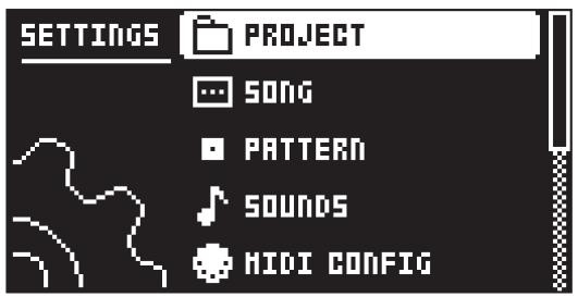
14.1 PROJECT

14.1.1 LOAD PROJECT
Load Project opens a project selection screen where you can choose a project to load. Note that the active project is not saved before loading the new project so remember to save the active project first. If you wish to create a new project, select CREATE NEW at the very bottom of the list. The new project is a blank slate.

If you load a new project, it overwrites the active project. Be sure to save your active project before you load another project.
14.1.2 SAVE PROJECT AS
Save Project opens a project selection screen where you choose a slot to save the active project too. [FUNC] + [SETTINGS] opens this screen if the project has not been saved previously.
14.1.3 MANAGE PROJECTS
MANAGE PROJECTS launches the PROJECT MANAGER menu. If you select a project in this menu and press the [RIGHT] arrow key a list of commands appear.
CLEAR Resets the project slot to a clean state.
DELETE Removes the project from the slot.
RENAME Opens a NAMING screen where you can rename the project file.
LOAD FROM Loads the selected project. Please note that this overwrites the active project.
SAVE TO Saves the active project to the selected slot.
TOGGLE Toggles write protection on or off. You can not overwrite, rename or erase write protected projects A lock symbols in front of the project name shows that the project is write protected.
INIT NEW Initializes an empty file slot with a clean project. This option is only available for empty project slots.
14.2 SONG
In this menu, you can perform tasks related to songs. You can also press [SONG MODE] + [UP] to open the SONG menu. For more information, please see “10.11 SONG MODE” on page 43.

14.2.1 RENAME
Opens a screen where you can rename the active song.
14.2.2 CLEAR
Clears the active song
14.2.3 LOAD
Opens a screen where you can select and load songs
14.2.4 SAVE TO PROJ
Saves the active song to the project.
14.3 PATTERN
Use the PATTERN menu to perform pattern management. Use the [UP] and [DOWN] arrow keys to move between the options. Press [YES] to confirm your selection. Press [NO] to exit the menu.

14.3.1 QUANTIZE
The quantization affects all micro timed and off grid trigs on the sequencers tracks. Change settings with DATA ENTRY knob E and F.

TRK. affects the trigs of the active track in real time. The higher the quantize value, the more the trigs are quantized. Press [T1-4] key to select what track to quantize. (0–127)
GLOBAL affects the trigs of all tracks in real time. The higher the quantize value, the more the trigs are quantized. (0–127)
Press [NO] to exit the menu.
14.3.2 RENAME
Opens a NAMING screen where you can rename the active pattern.
14.3.3 CLEAR
WHOLE PATTERN Clears the active pattern's sequencer and Sounds data. A prompt appears when you select this option. Press [YES] to clear, or [NO] to cancel the operation. Note that you do not lose any pattern information permanently until you save the pattern to the same pattern slot.
SOUNDS DATA Clears the active patterns four Sounds. All sequencer data will remain unchanged. A prompt appears when you select this option. Press [YES] to clear, or [NO] to cancel the operation. Note that until you save the pattern to the same pattern slot that you loaded from, you do not lose any Sound information permanently.
SEQUENCE DATA Clears the active pattern's sequence data. All sounds remain unchanged. A prompt appears when you select this option. Press [YES] to clear, or [NO] to cancel the operation. Note that until you save the pattern to the same pattern slot that you loaded from, you do not lose any sequencer information permanently.
14.3.4 SAVE TO PROJ
You must have saved the project at least once before you can save pattern information.
WHOLE PATTERN Saves the active pattern's sequence data and four Sounds to the +Drive. A prompt appears when you select this option. Press [YES] to save, or [NO] to cancel the operation.
SOUNDS DATA Saves the active pattern's four Sounds to the +Drive. A prompt appears when you select this option. Press [YES] to save, or [NO] to cancel the operation.
SEQUENCE DATA Saves the active pattern's sequence data to the +Drive. A prompt appears when you select this option. Press [YES] to save, or [NO] to cancel the operation.
For more information, please see “10.9.7 TEMPORARY SAVE AND RELOAD PATTERN COMMANDS” on page 42.
14.3.5 RELOAD FROM PROJ
You must have saved the pattern at least once before you can reload pattern information.
WHOLE PATTERN Reloads the active pattern's sequence data and four Sounds from the +Drive. A prompt appears when you select this option. Press [YES] to reload, or [NO] to cancel the operation.
SOUNDS DATA Reloads the active pattern's four Sounds from the +Drive. A prompt appears when you select this option. Press [YES] to reload, or [NO] to cancel the operation.
SEQUENCE DATA Reloads the active patterns all sequence data from the +Drive. A prompt appears when you select this option. Press [YES] to reload, or [NO] to cancel the operation.
14.3.6 IMPORT/EXPORT
Here you can manage the sounds on the Digitone. You can also press [FUNC] + [SONG MODE] to access this menu directly.
IMPORT SOUND Imports (copies) a Sound from the +Drive to the active pattern. Turn the LEVEL/DATA knob or press [UP]/[DOWN] to scroll through the list. Press [YES] to select a Sound and then press [T1-4] to select the track to where you want to assign the sound.
EXPORT SOUND Exports (saves) the active track's Sound to the +Drive. Turn the LEVEL/DATA knob or press [UP]/[DOWN] to choose a destination memory slot. Press [YES] to export the sound. Name the Sound and press [YES] again to confirm the export.
MANAGE SOUNDS Opens the SOUND MANAGER. For more information, please see “14.4.2 SOUND MANAGER” on page 69.
14.3.7 AUDIO ROUTING (PATTERN)
Here you find number of audio routing options that affects the Digitone on a pattern level. You can also set the audio routing on a global level. For more information, please see “14.7 AUDIO ROUTING (GLOBAL)” on page 74.

USE GLOBAL SETTING uses, when ticked, the global audio routing settings for the active pattern.
ROUTE TO MAIN Use this option to customize which of the 4 tracks + 3 effects (Chorus, Delay, Reverb) that sends audio through the master effect (Distortion) to the MAIN OUT outputs. Use the [TRACK] keys and the [SYN2], [FLTR], and [AMP] [PARAMETER] keys to activate/deactivate send from each track
and effect. Green keys signal send to main. Red keys signal do not send to main. Note that each track still sends to its TRACK OUTPUTS.
SEND TO FX Use this option to customize which of the 4 tracks + the Chorus and the Delay effects that sends audio to the effects (Chorus, Delay, Reverb). Use the [TRACK] keys and the [SYN2], and [FLTR] [PARAMETER] keys to activate/deactivate send from each track and effect. Green keys signal send to the effects. Red keys signal do not send to the effects.

• Audio from the TRACK OUTPUTS is always without any effects.
- Tracks that are routed to not send audio to MAIN OUT still send audio on separate outputs in Overbridge.
14.4 SOUNDS
In this menu you can browse and manage Sounds in the +Drive Sound library or the Sound pool of the active project. Other menu options let you clear the track Sound and rename the track Sound. Use the [UP] and [DOWN] arrow keys or LEVEL/DATA to move between the options. Press [YES] to confirm your selection. Press [NO] to exit the menu.

14.4.1 SOUND BROWSER

Press [FUNC] + LEVEL/DATA to open the SOUND BROWSER. The SOUND BROWSER is used to preview and load Sounds. This menu shows a list of all sounds in the +Drive Sound library or the Sound pool. Scroll the list by turning the LEVEL/DATA knob or by pressing [UP]/[DOWN]. Press [BANK] + [TRIG 9-16] to select Sound bank A-H. You can preview a Sound by highlighting it in the list and use the [TRIG] keys to play the Sound. Press [NOTE] + [UP]/[DOWN] to change octave up and down on the Sound you preview. Press [YES] to load the highlighted Sound.
Press [LEFT] to access the SORTING menu. Press [YES] to execute the commands. Press [NO] or the [RIGHT] arrow key to exit the menu.

VIEW POOL lists Sounds available in the Sound pool of the active project. The command is only available when you browse the +Drive Sound library.
VIEW +DRIVE lists Sounds available on the +Drive Sound library. The command is only available when you browse the Sound pool of the active project.
SORT ABC sorts the Sounds in alphabetical order. This option is only available when SORT 123 is active.
SORT 123 sorts the Sounds by slot number. This option is only available when SORT ABC is active.
FILTER opens a list where Sounds are arranged according to tags. Select and deselect tags by pressing [YES]. Multiple tags can be selected. Exit the tag list by pressing [NO].
SEARCH gives you the option to perform a text search and list all Sounds with names matching or including the text input. For more information, please see “6.5 THE NAMING SCREEN” on page 19 on how to enter text.

- Press the [TRIG] keys to preview the currently selected Sound.
Please note that the active tracks current effects settings affect the previewed Sound - Press [BANK] + [TRIG 9–16] to select Sound bank.
- You can also press a [TRACK] key twice quickly to open the SOUND BROWSER. The SOUND BROWSER can also be accessed by pressing [FUNC] + LEVEL/DATA.
14.4.2 SOUND MANAGER
You use the SOUND MANAGER to manage sounds, for example, import, export, rename, and tag sounds. Sounds can be saved, loaded, renamed, tagged et cetera. Opening this menu shows a list of all sounds found in the +Drive Sound library or the Sound pool. Turn the LEVEL/DATA knob or press [UP]/[DOWN] to scroll through the list. Press [BANK] + [TRIG 9-16] to select Sound bank A-H. You can preview a Sound by highlighting it in the list and use the [TRIG] keys to play the Sound Press [NOTE] + [UP]/[DOWN] to change octave up and down on the Sound you preview.
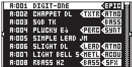
Press [LEFT] to access the SORTING menu. Press [YES] to execute the commands. Press [NO] or the [RIGHT] arrow key to exit the menu.

VIEW POOL lists Sounds available in the Sound pool of the active project. The command is only available when you browse the +Drive Sound library.
VIEW +DRIVE lists Sounds available on the +Drive Sound library. The command is only available when you browse the Sound pool of the active project.
SORT ABC sorts the Sounds in alphabetical order. This option is only available when SORT 123 is active.
SORT 123 sorts the Sounds by slot number. This option is only available when SORT ABC is active.
FILTER opens a list where Sounds are arranged according to tags. Select and deselect tags by pressing [YES]. You can select multiple tags. Exit the tag list by pressing [NO].
SEARCH gives you the option to perform a text search and list all Sounds with names matching or including the text input. For more information, please see “6.5 THE NAMING SCREEN” on page 19 on how to enter text.
Press [RIGHT] to access the SOUND OPERATIONS menu. The available operations affects the selected Sound. Press [YES] to apply the commands to the selected Sound. Press [NO] or the [LEFT] arrow key to exit the menu.

LOAD TO TRK loads the selected Sound to the active track and makes it a part of the active pattern.
COPY TO... Copies the selected Sounds to one of the following:
SOUND POOL copies the selected Sounds to the first free slots of the Sound pool.
+DRIVE copies the selected Sounds to the first free slots of the +Drive Sound library.
+BANK (A–H) copies the selected Sounds to the first free slots of a specific bank inside the +Drive.
SAVE TO HERE saves the active track Sound to the selected slot.
RENAME Opens a screen where you can rename the selected Sound.
EDIT TAGS opens a menu where Sounds can be tagged. Sounds can have any number of tags, but only the first two shows on the sound list. Press [YES] to apply or remove tags. Highlight
DELETE deletes the Sound or the selected Sounds.
SELECT ALL selects all Sounds in the list.
SELECT UNUSED selects all Sounds that are not used in any pattern in the project from the Sound pool. The Sounds are not removed from the +Drive Sound library. Then select DELETE to remove the selected sounds from the project's Sound pool. The SELECT UNUSED command is only available when you browse the Sound pool of the active project.
DESELECT ALL deselects all Sounds in the list.
TOGGLE enables or disables write protection for the selected Sounds. When a Sound is write-protected, it cannot be overwritten, renamed, tagged or deleted. A write-protected Sound has a padlock symbol next to its name. The command is only available when you browse the +Drive Sound library.
SEND SYSEX sends the selected Sounds as SysEx data.

- Sounds in the +Drive Sound library are organized into eight banks, ranging from A to H. Each bank can contain 256 Sounds. Press [BANK] + [TRIG 9–16] keys to view the Sounds in a specific bank.
- Press the [TRIG] keys to preview the currently selected Sound. Please note that the active tracks current effects settings affect the previewed Sound
- Several Sounds can be simultaneously affected by the commands available in the SOUND OPERATIONS menu. Select/deselect individual Sounds by highlighting them and pressing [YES].
- Press [FUNC] + [UP]/[DOWN] for faster scrolling in the sound list.
14.4.3 CLEAR TRACK SOUND
Sets the PARAMETER page parameters of the active track to their default values. When selecting this option, a prompt will appear. Press [YES] to initialize the parameters or [NO] to cancel the operation. Note that no saved parameter information are permanently lost until the Sound is saved to the same slot it was loaded from.
14.4.4 RENAME TRACK SOUND
Opens the NAMING menu where you can rename the Sound of the active track.
14.4.5 SETUP
Opens the SOUND SETUP menu. For more information, please see "9.5 SOUND SETUP MENU" on page 28.
14.5 MIDI CONFIG
In this menu you find various sub-menus dealing with the MIDI functionality.

14.5.1 SYNC
Controls how Digitone receives and sends MIDI clock and transport commands. Change settings by using the [LEFT]/[RIGHT] arrow keys or the [YES] key.

CLOCK RECEIVE sets whether or not Digitone responds to MIDI clock sent from external devices.
CLOCK SEND sets whether or not Digitone transmits MIDI clock.
TRANSPORT RECEIVE sets whether or not Digitone responds to MIDI transport messages sent from external devices.
TRANSPORT SEND sets whether or not Digitone transmits MIDI transport messages.
PROG CH RECEIVE sets whether or not Digitone responds to incoming program change messages, which is useful when wanting to select patterns externally. The MIDI channel that listens to incoming program change messages is set in the MIDI CHANNELS menu. For more information, please see "14.5.3 CHANNELS" on page 72.
PROG CH SEND sets whether or not Digitone sends program change messages when patterns change. You set the MIDI channel that sends program change messages in the MIDI CHANNELS menu. For more information, please see “14.5.3 CHANNELS” on page 72.
14.5.2 PORT CONFIG
In this menu you find the MIDI port related settings. Change settings by using the [LEFT]/[RIGHT] arrow keys.

TURBO SPEED press [YES] to start the turbo speed negotiation. The device chooses the optimal speed automatically. Please note that you must use a MIDI interface that supports the Turbo-MIDI protocol.
OUT PORT FUNC selects what type of signal the MIDI OUT port sends.
MIDI makes it possible for the port to send out MIDI data.
DIN 24 makes the port send DIN 24 sync pulses. No MIDI data is transferred over the port when this option is selected.
DIN 48 makes the port send DIN 48 sync pulses. No MIDI data is transferred over the port when this option is selected.
THRU PORT FUNC selects what type of signal the MIDI THRU port sends. The settings are the same as for OUT PORT FUNCTIONALITY.
INPUT FROM selects the input MIDI data port.
DISABLED receives no MIDI data.
MIDI receives MIDI data from the MIDI IN port.
USB receives MIDI data from the USB port.
MIDI+USB receives MIDI data from the MIDI IN and USB ports.
OUTPUT TO selects the output MIDI data port.
DISABLED sends no MIDI data.
MIDI sends MIDI data to the MIDI OUT port.
USB sends MIDI data to the USB port.
MIDI+USB sends MIDI data to the MIDI OUT and USB ports.

If MIDI+USB is selected in the OUTPUT TO settings, MIDI data will limit the USB speed. When sending large chunks of data, make sure you only use the USB setting.
OUTPUT CH selects whether the knobs send data on the AUTO channel or the track channel.
PARAM OUTPUT selects what type of MIDI messages the DATA ENTRY knobs send. For information about which CC/NRPN parameters that are sent, please see "APPENDIX B: MIDI IMPLEMENTATION" on page 95.
NRPN sends NRPN MIDI messages.
CC sends CC MIDI messages.
ENCODER DEST controls whether the DATA ENTRY and LEVEL/DATA knobs send MIDI data or not. When set to INT, the knobs only affect the Digitone and send no MIDI data. When set to INT + EXT, the knobs affect the Digitone and also sends MIDI data to external devices.
TRIG KEY DEST controls whether the [TRIG] keys sends MIDI data or not. When set to INT, the [TRIG] keys only affect the Digitone and sends no MIDI data. When set to INT + EXT, the [TRIG] keys affect the Digitone, and also send MIDI data to external devices. When set to EXT, the [TRIG] keys send MIDI data to external devices but do not affect the Digitone.
MUTE DEST controls whether activating/deactivating mutes send MIDI data or not. When set to INT, mutes only affect the Digitone and no MIDI data is sent. When set to INT + EXT, mutes affect the Digitone and also send MIDI data to external devices. When set to EXT, mutes send MIDI data externally but do not affect the Digitone.
RECEIVE NOTES sets whether or not it is possible to use an external MIDI keyboard or controller to play the Digitone.
RECEIVE CC/NRPN sets whether or not it is possible to use an external MIDI device to control Digitone parameters with CC/NRPN data.
14.5.3 CHANNELS
This menu handles the MIDI channel configuration.

TRACK 1–4 CHANNEL selects dedicated MIDI track channel that controls the synth tracks. It also sets the MIDI channel for the MIDI messages the DATA ENTRY knobs on the chosen track send. An OFF setting makes the track disregard any incoming MIDI messages.
MIDI 1-4 CHANNEL selects dedicated MIDI track channel that controls the MIDI tracks. It also sets the MIDI channel for the MIDI messages the DATA ENTRY knobs on the chosen track send. An OFF setting makes the track disregard any incoming MIDI messages.
FX CHANNEL selects dedicated MIDI track channel that controls the FX parameters. It also sets the MIDI channel for the MIDI messages the DATA ENTRY knobs on the FX pages send. An OFF setting makes the track disregard any incoming MIDI messages.
AUTO CHANNEL selects the MIDI channel that gives access to the currently active track. If an external MIDI keyboard connected to Digitone sends MIDI data on this channel, the keyboard controls the active track. This function is useful when you want to change quickly between the active synth tracks to play different Sounds. The Digitone also uses the AUTO channel to record to the MIDI tracks from external MIDI controllers. The default AUTO channel is 10.
PROG CH IN CH selects the MIDI channel that listens for incoming program change messages. An AUTO setting uses the AUTO channel. Enable Digitone to respond to program change messages in the MIDI SYNC menu. For more information, please see “14.5.1 SYNC” on page 71.
PROG CH OUT CH selects the MIDI channel that sends program change messages when changing patterns. The AUTO setting uses the AUTO channel. Enable Digitone to send program change messages in the SYNC menu. For more information, please see "14.5.1 SYNC" on page 71.
MULTI MAP CH selects the MIDI channel that receives MIDI messages from external MIDI keyboard/ controllers, to access the MULTI MAP mode. If you use an external keyboard or controller you can always access the MULTI MAP mode whether you are in MULTI MAP mode on or not. For more information, please see “14.9.1 MULTI MAP EDIT” on page 75.
14.6 SYSEX DUMP
In the SYSEX DUMP menu, projects, patterns, and Sounds can be sent and received. Select a menu option using [UP]/[DOWN] or the TRACK LEVEL knob. Press [YES] to open the highlighted menu selection.

When receiving or sending SysEx data, the MIDI ports or the USB port of the Digitone should be connected to the external sending/receiving device.
If the Digitone is sending or receiving SysEx data through the MIDI ports, use the Elektron TM-1 USB MIDI interface for up to 10x transfer speeds.
If the external device is a computer, we recommend using our free SysEx utility C6, which can be downloaded from the Elektron website.
14.6.1 SYSEX SEND
Here projects, patterns, and Sounds can be sent to an external device via the MIDI OUT port or the USB port of the Digitone.

The column to the left selects what will be backed up. Select the column using the [LEFT] arrow key. Use the [UP]/[DOWN] keys or the TRACK LEVEL knob to navigate in the column. The SysEx data send alternatives located in the column to the right will change depending on the selection made in the left column. Press the [RIGHT] arrow key to access this column. Use the [UP]/[DOWN] keys or the TRACK LEVEL knob to select what will be sent. Press [YES] to initiate the SysEx send procedure.
PROJECT will send the active project (settings, patterns, Sounds in the Sound Pool) to the receiving device.
PATTERN will send the selected pattern to the receiving device.
SOUNDS will send the selected Sound bank to the receiving device.

- Backing up your data regularly is important!
- Before initiating a SysEx send, first, make sure the receiving device is listening for data to be sent.
14.6.2 SYSEX RECEIVE
Here projects, patterns, and Sounds can be received from an external device via the MIDI IN port or the USB port of the Digitone.

The column to the left selects what will be received. Select the column using the [LEFT] arrow key. Use the [UP]/[DOWN] keys or the TRACK LEVEL knob to navigate in the column. The SysEx data receive alternatives located in the column to the right will change depending on the selection made in the left column. Press the [RIGHT] arrow key to access this column. Use the [UP]/[DOWN] keys or the TRACK LEVEL knob to select what will be received. Press [YES] to initiate the SysEx receive procedure. The Digitone starts listening to incoming data. Press [NO] to stop listening.
ANYTHING listens to and receives any viable SysEx data (patterns, settings, Sounds).
PATTERN stores a received pattern to the selected pattern slot.
SOUNDS stores a received Sound to the selected bank in the +Drive Sound library. The option ANY-WHERE will place the Sound in the first free slot available. You can see the amount of free slots to the right of the bank indication.
14.7 AUDIO ROUTING (GLOBAL)
Here you find number of audio routing options that affects the Digitone on a global level. You can also set the audio routing on a pattern level. For more information, please see “14.3.7 AUDIO ROUTING (PATTERN)” on page 67.

14.7.1 ROUTE TO MAIN
Use this option to customize which of the 4 tracks + 3 effects (Chorus, Delay, Reverb) that sends audio through the master effect (Distortion) to the MAIN OUT outputs. Use the [TRACK] keys and the [SYN2], [FLTR], and [AMP] [PARAMETER] keys to activate/deactivate send from each track and effect. Green keys signal send to main. Red keys signal do not send to main.
14.7.2 SEND TO FX
Use this option to customize which of the 4 tracks + the Chorus and the Delay effects that sends audio to the effects (Chorus, Delay, Reverb). Use the [TRACK] keys and the [SYN2], and [FLTR] [PARAMETER] keys to activate/deactivate send from each track and effect. Green keys signal send to the effects. Red keys signal do not send to the effects.
14.7.3 INT TO MAIN
Sets if Digitone sends internal audio to the MAIN OUT and HEADPHONES OUT or not when used with Overbridge or as a class compliant audio device.
OFF No sound is sent to main out and headphones out.
AUTO No sound is sent to main out and headphones out when Overbridge is available and/or streaming audio, if not, the sound is sent to main out and headphones out.
ON Sound is always sent to main out and headphones out.
14.7.4 USB TO MAIN
Sets the amount of amplification of the sound that is streamed over USB to the Digitone main out when used with Overbridge or as a class compliant audio device. (0 dB–+18 dB)

Tracks that are routed to not send audio to MAIN OUT still send audio on separate outputs in Overbridge.
14.8 GLOBAL FX/MIX
In the GLOBAL FX/MIX menu, you can select several parameter pages whose parameters will (when selected) act on a global level instead of on a pattern level. Then the parameter's settings on that page will not only affect the active pattern but will also affect all the other patterns in the project. The parameters text/value graphics are then inverted. Use the [LEFT]/[RIGHT] keys to select or deselect the parameter pages you wish to function on a global level. For more information, please see "13. FX PARAMETERS" on page 60

14.9 CONTROL
14.9.1 MULTI MAP EDIT
The MULTI MAP mode gives you the possibility to map different functions to single notes or note ranges that can be played on the [TRIG] keys or an external MIDI controller/keyboard. The functions that can be mapped are: Internal triggering of Sounds on any track, triggering of MIDI notes on any MIDI channel and the ability to trig patterns. Multi map also allows custom mapped keyboards splits, pattern triggering per key, Sound trig per key, MIDI trig of external synths, and more. In the MULTI MAP mode, for example, full drum kits, bass lines, and lead sounds can be played simultaneously. This makes it ideal for performances and live improvisations.
It is possible to map one unique function for each of the 128 keys of the entire MIDI keyboard range. There are eight slots available for each project to store a complete multi map in each slot.
The MULTI MAP mode is active when you are in the MULTI MAP menu. Exit the MULTI MAP menu to turn the MULTI MAP mode off.

If you use an external keyboard or controller you can always access the MULTI MAP mode if you use the dedicated MULTI MAP MIDI channel. For more information, please see "14.5.3 CHANNELS" on page 72.
Highlight MULTI MAP EDIT and then use the [LEFT]/[RIGHT] keys to select the multi map slot you wish to edit, and then press [YES] to open the MULTI MAP menu.

MULTI MAP MENU
In the MULTI MAP menu, you find all ranges in the selected multi map slot. The multi map settings are stored together with the project.

RANGES are the basic building blocks of the multi map. They define what function that is assigned to each key or key range. A multi map can contain up to 128 ranges. The ranges can be set within the note interval C0–G10 If no ranges exist, select ADD RANGE.

A popup screen appear where you can set the following:
START sets the note on the keyboard on which to start the desired keyboard range. You can also press and hold DATA ENTRY knob E, and then press the desired key on a connected external keyboard to set this parameter.
SPAN sets how many semitones the range spans. You can also press and hold DATA ENTRY knob F, and then press the desired key on a connected external keyboard to set this parameter.
RANGES sets the amount of ranges you wish to create. The ranges are placed after each other on the keyboard, with the first range starting at the note set by the START parameter. All ranges has the same span and is defined by the SPAN parameter.
FUNCTION selects one of the four types of functionality that an entry can have: OFF, PAT.PLAY, INT.TRIG and EXT.TRIG.
The note values at the top of the popup screen indicate (from left to right):
G4 The end note of the range before the current. If no range exists before the current range, this indicator is not shown.
(D5) The end note of the selected span.
D#5 The start note of the range after the current. If no range exists after the current range, this indicator is not shown.
RANGE OPERATIONS MENU
In this menu you can perform a number of operation to the ranges within the multi map. Highlight a range in the MULTI MAP menu and then press the [RIGHT] arrow key to open the RANGE OPERATIONS menu.

EDIT RANGE opens the RANGE EDIT menu. Press [YES] to select.
ADD BEFORE creates a new range with a range ending on the note preceding the current range. Press [YES] to select.
ADD AFTER creates a new range beginning on the note succeeding the current range Press [YES] to select.
DELETE RANGE deletes the current range Press [YES] to select.
DELETE ALL deletes all ranges in the current Multi map slot. Press [YES] to select.
RANGE EDIT MENU
To edit a multi map range, in the MULTI MAP menu, use the [UP]/[DOWN] arrow keys to select the range you want to edit and then press [YES] to open the RANGE EDIT menu. You can also use the EDIT RANGE option in the RANGE OPERATIONS menu to open the RANGE EDIT menu.

- You can play the specified range on the [TRIG] keys or an external MIDI controller/keyboard to instantly try out the map entries as you are editing.
- If you use an external MIDI keyboard/controller, remember to set the external MIDI device to the assigned MULTI MAP CHANNEL. For more information, please see "14.5.3 CHANNELS" on page 72.
FUNCTION selects one of the four types of functionality that an entry can have: NONE, PAT.PLAY, INT.TRIG, and EXT.TRIG.
- NONE sets a keyboard key or range that are not used for any function. It is convenient for defining a ‘no-play’ zone on the keyboard between two or more sections with different Sounds or functions.
RANGE LOW sets the note on the keyboard on which to start the desired keyboard range.
RANGE HIGH sets the note on the keyboard on which to end the desired keyboard range.

You can also set RANGE HIGH and RANGE LOW by highlighting the parameter, press and hold [YES], and then press the desired key on an external keyboard or controller.
- PAT.PLAY maps a chosen pattern to a specific keyboard range.
RANGE LOW sets the note on the keyboard on which to start the desired keyboard range.
RANGE HIGH sets the note on the keyboard on which to end the desired keyboard range.
PATTERN selects which pattern (A01–H16) of the active project that plays when you press a keyboard key in the range specified above. Set to CUR if the current pattern should play.
PATTERN INC selects the increment with which the pattern increases for each successive key in the specified range. For example, if set to 1, each successive key starts pattern A01, A02, A03 and so on. Set to 2 it plays pattern A01, A03, A05 et cetera. Set to 0 if the same pattern as set in PATTERN above should play for every key in the range.
- INT.TRIG sets the chosen keyboard range to control specific Sounds from the Sound pool or the +Drive Sound library.
RANGE LOW sets the note on the keyboard on which to start the desired keyboard range.
RANGE HIGH sets the note on the keyboard on which to end the desired keyboard range. If a single key is to be mapped, set to the same note as RANGE LOW.

The [TRIG] keys on the Digitone can only play in a fixed range, C0–C1 and cannot be transposed. Only lit keys are playable.
TRACK sets which track the selected keyboard range plays. AUTO plays the active track, while TRK 1, TRK 2, TRK 3, and TRK 4 sets the range to play the specific synth track of your choice.
NOTE sets which note the start of the chosen keyboard range plays. It should be set to the same note as RANGE LOW If you do not want any offset.
NOTE INC defines by what increment the following notes played increases. For instance, if this value is set to 2, and the first note in the range is C5, the following note in the range plays D5, the one after that E5 and so on. If set to 0, all notes in the keyboard range play the same note (as set in NOTE above). If a 1:1 correspondence is desired, set to 1.
SOUND SLOT sets which of the 128 Sounds from the active project's Sound pool is played by the keyboard range. If set to OFF, the track Sound of the chosen by TRACK above plays. For more information, please see "9.1.1 ADDING SOUNDS TO THE SOUND POOL" on page 28.
SND SLOT NOTE INC sets by what increment the next key in the chosen keyboard range plays the next sound slot Sound. If set to 0, the same Sound as defined above play across the whole defined range. If set to 1, it plays the next successive sound slot Sound for each successive key pressed. Setting the value to 2 play every other Sound starting from the sound slot, setting it to 4 every fourth and so on.

Setting a specific SOUND SLOT and setting SND SLOT NOTE INC to 1 is convenient if you wish to define, for example, a succession of drum sounds that you have stored in a given sound slot range to be mapped to a specific section of the keyboard.
You can then record the track in LIVE RECORDING mode, and the sound slot changes are then recorded as sound locks to the sequencer.
SND SLOT VEL INC sets a range of how many Sound slots you can play between a velocity of 1 to 127. If you set this parameter to 0, the Sound as defined in SOUND SLOT plays across the whole velocity range. If set to 1, it plays the Sound defined in SOUND SLOT between velocity 1–63 and the next successive sound slot Sound between velocity 64–127. If set to 2, it plays the Sound defined in SOUND SLOT, and the next two successive sound slot Sounds evenly distributed in the velocity range 1–127 and so on. Selecting a negative value plays Sounds from sound slots preceding the slot of the Sound defined in SOUND SLOT.

Setting a specific SOUND SLOT, and then use SND SLOT NOTE INC, and SND SLOT VEL INC lets you, for example, design a “multi-layered” drum kit with 4 sounds for each drum type. Set SND SLOT NOTE INC to 4 so each following note advances +4 slots, and SND SLOT VEL INC to +3 so that velocity advances up to +3 slots within that 4-slot range.
FIXED VEL will, if set to OFF, make the velocity sensitivity of an external keyboard work as usual. You can also set it to a constant specific value between 1 and 127, 1 being the lowest and 127 the highest possible velocity.
- EXT.TRIG allows MIDI control of external equipment for a chosen keyboard range.
RANGE LOW sets the note on the keyboard on which to start the desired keyboard range.
RANGE HIGH sets the note on the keyboard on which to end the desired keyboard range. If a single key is to be mapped, set to the same note as RANGE LOW.
CHANNEL sets the MIDI channel on which the MIDI note messages are sent.
NOTE sets which note the start of the chosen keyboard range plays.
NOTE INC defines by what increment the following notes played increases.
FIXED VEL will, if set to OFF, make the velocity sensitivity of the MIDI keyboard work as usual. You can also set it to a constant specific value between 1 and 127.
14.10 SYSTEM
The System menu contains USB CONFIG, OS UPGRADE and FORMAT +DRIVE options for the Digitone.

14.10.1 USB CONFIG
Here you find several settings related to Overbridge and USB audio. Selecting one mode disables the other two modes.

OVERBRIDGE enables Overbridge functionality. For more information, please see "6.6 OVERBRIDGE" on page 20.
USB MIDI select this option If you wish to send and receive MIDI over USB.
USB AUDIO/MIDI sets the Digitone to send and receive audio and MIDI over USB. Select this option if you want to use the Digitone together with a class compliant USB audio host. For more information, please see "6.7 CLASS COMPLIANT DEVICE" on page 20.
14.10.2 LED BACKLIGHT
Switches the key LEDs backlight on/off.
14.10.3 LED INTENSITY
Sets the brightness of the key LEDs and screen. Use the [LEFT]/[RIGHT] keys to change the setting (LOW, MID, MAX).

Press [SETTINGS] + [TRIG 1–3] to set the intensity of the key LEDs and screen. [SETTINGS] + [TRIG 9] toggles the key LEDs backlight on/off.
14.10.4 REMEMBER SUBPAGE
Will, when selected, remember which PARAMETER page's subpage you last used and access this page again the next time you press the same [PARAMETER] key. Use the [YES] key to toggle this setting. (ON, OFF).
14.10.5 OS UPGRADE
Use this menu option when you want to upgrade the Digitone OS. To send the OS file, use our free Elektron Transfer software. Elektron Transfer can be downloaded from the Elektron website.
For the transfer to be possible, the device sending the OS file must be connected to the USB port of Digitone.
Please note that the Digitone will not appear as an icon on your computer desktop.
- Download the Digitone OS file from the Elektron website.
- Connect the Elektron device to the computer via USB.
- Open the Transfer application on your computer.
- On the Transfer CONNECTIONS page, set the MIDI IN and MIDI OUT ports to your Elektron device.
- On the Transfer DROP page, drag and drop the OS file. The OS file is then automatically transferred to the Elektron device and the OS update initiates. A progress bar is visible on device screen when receiving the OS.
- On your device. Press [YES] to confirm the OS update.
When the update is done, the Digitone will reboot.

If your current Digitone OS does not fully support Transfer, you will be automatically directed to Transfer's LEGACY OS UPGRADE page after you drag and drop the OS file on the Transfer DROP page. Follow the instructions on the LEGACY OS UPGRADE page to proceed with the OS upgrade.
14.10.6 FORMAT +DRIVE
You can delete all projects and Sounds from the +Drive. Tick the PROJECTS+SOUNDS box, and then select ERASE SELECTED DATA, and press [YES] to proceed with the formatting. A prompt appears asking if you are sure you want to continue with the formatting procedure. Press [YES] to confirm.

PROJECTS+SOUNDS erases all projects and sounds. Press the [LEFT] or [RIGHT] arrow keys to tick/untick this box.
14.10.7 MASTER TUNE
Sets the master tune for the Digitone. The default setting is the international standard middle A, 440.0 Hz.
15. STARTUP MENU
Press and hold the [FUNC] key while powering up the Digitone to access the STARTUP menu. Here you can perform a variety of tasks. Press the corresponding [TRIG] key to choose one of the alternatives.
15.1 TEST MODE
Press the [TRIG 1] key to enter TEST mode.

For testing purposes, a short sound is sent through all outputs of the unit.
You can perform this self-test if you have any trouble with your Digitone and suspect it may be due to a hardware problem. Use the [UP] and [DOWN] keys to scroll through the test log. A fully functional device should not report any errors. Please contact Elektron support or the retailer that you bought your Digitone from if the device log reports an error.
15.2 EMPTY RESET
Press the [TRIG 2] key to perform an empty reset. The reset erases all patterns and sounds, but the data on the +Drive remains intact.
15.3 FACTORY RESET
Press the [TRIG 3] key to perform a factory reset. When you perform a factory reset on the Digitone, it overwrites and re-initializes the active RAM project (including all pattern and global data). The +Drive project slot 1 is overwritten and re-initialized with factory preset patterns, sounds, and settings. Sound bank A and B are overwritten with the factory sounds.
If you wish to keep the active project, remember to save it to a +Drive project slot higher than 1 before you perform a factory reset.
15.4 OS UPGRADE
Use this menu option if you for some reason cant upgrade the Digitone OS using the standard procedure in the SYSTEM menu. To send the OS file, use our free Elektron Transfer software. The Elektron Transfer can be downloaded from the Elektron website.
- Download the Digitone OS file from the Elektron website.
- Connect the Digitone's MIDI IN port to the MIDI OUT port of the computer's MIDI interface.
- Hold down the [FUNC] key while powering on Digitone. This takes you to the STARTUP menu.
- Press the [TRIG 4] key to enter OS UPGRADE mode.
- Open the Transfer application on your computer. On the Transfer CONNECTION page, click "go to the SYSEX TRANSFER page".
- On the SYSEX TRANSFER page, click "OS Upgrade via device startup menu", and then follow the on-screen instructions.
When the update is done, the Digitone will reboot.

USB MIDI transfer is not possible when upgrading the OS from the STARTUP menu.
15.5 EXIT
Press the [TRIG 5] key to exit the STARTUP menu.
16. SETUP EXAMPLES
The Digitone likes to play with other machines. Whether it uses its ability to sync and play with legacy machines, is paired with the Digitone or controls other synthesizers.
16.1 DIGITONE WITH A MONOPHONIC BASS MACHINE

The DIN sync capabilities of the Digitone allows you to use gear from yesteryear.
In this example, a legacy monophonic bass machine is used alongside the Digitone. The Digitone can stop, start and control the tempo of the bass machine.
- Prepare a bassline pattern on the bass machine.
- Connect the output of the bass machine to the mixer using a Mono jack 6.3 mm male cable.
- Connect the Digitone audio outputs to the mixer using 2 x Mono or Stereo jack 6.3 mm male cables.
- Use a DIN connector cable to connect the MIDI OUT of the Digitone to the SYNC IN of the bass machine.
- On the Digitone, press [SETTINGS], and then navigate to MIDI CONFIG > PORT CONFIG and set OUT PORT CONFIG to DIN24.

- Press [PLAY] on the Digitone.
16.2 DIGITONE TOGETHER WITH THE DIGITAKT

Digitone works very well together with the Digitakt, and you can, for example, route the audio from the Digitakt through the Digitone and sync the tempo of the sequencers.
- Use a standard MIDI cable to connect the Digitakt MIDI OUT jack with the Digitone's MIDI IN jack.
- Use two TR or TRS cables to connect the OUTPUT L/R from the Digitakt to the INPUT L/R on the Digitone.
- On the Digitakt, press [SETTINGS], and then navigate to MIDI CONFIG > PORT CONFIG and set OUT PORT FUNC to MIDI.
- In the same menu set OUTPUT to MIDI.
- Press [SETTINGS], and then navigate to MIDI CONFIG > SYNC and set CLOCK SEND and TRANSPORT SEND to ON.
- On the Digitone, press [SETTINGS], and then navigate to MIDI CONFIG > PORT CONFIG and set INPUT FROM to MIDI.
- Press [SETTINGS], and then navigate to MIDI CONFIG > SYNC and set CLOCK RECEIVE to ON.
- Press [PLAY] on the Digitakt
- On the Digitone, press [FUNC] + [LFO] to open the MASTER page.
- Adjust the IN L/R to set the level of the incoming audio from the Digitakt.
- Set LPAN to L64 and RPAN to R63.
- Adjust the CHR, DEL and REV parameters to add the Digitone's send effects to the Digitakt's audio.

16.3 CONTROLLING A SYNTHESIZER USING THE MIDI TRACKS

Digitone has extensive MIDI sequencing capabilities and can use its MIDI tracks to control other MIDI-equipped synthesizers.
- Use a standard MIDI cable to connect the Digitone MIDI OUT jack with the synthesizer's MIDI IN jack.
- On the Digitone, press [SETTINGS], and then navigate to MIDI CONFIG > PORT CONFIG and set OUT PORT FUNC to MIDI.
- In the same menu set OUTPUT TO to MIDI.
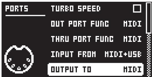
- On the main screen, press [MIDI] and then [T1-4] to select a MIDI track.
- Press [SYN1] and use the CHAN parameter to select a MIDI channel for the tracks output data.
- Make sure to set your synthesizer to receive MIDI input in a way that corresponds to the settings you made in the Digitone.
You are now ready to use the Digitone sequencer to control your synthesizer. For more information about using the Digitone sequencer, please see “10. THE SEQUENCER” on page 32.
17. USEFUL KEY COMBINATIONS
Use the key combinations below to speed up your workflow.
GENERAL
[FUNC] + [REC] performs a copy command. The action depends on the currently active page or mode.
[FUNC] + [PLAY] performs a clear command. The action depends on the currently active page or mode.
[FUNC] + [STOP] performs a paste command. The action depends on the copied content.
TRACK/BANK/PATTERN SELECT
[T1-4] keys to select a synth track.
[MIDI] and then [T1-4] keys to select a MIDI track.
[BANK] + [TRIG 9-16] keys to select a bank.
[PTN] + [TRIG 1-16] keys to select a pattern.
NAMING
[FUNC] + [ARROW] (on the NAMING screen) to choose a letter.
[FUNC] + [NO] (on the NAMING screen) to erase a letter.
SAVING AND RELOADING
[FUNC] + [SETTINGS] saves the active project.
[FUNC] + [YES] temporary saves the active pattern.
[FUNC] + [NO] reloads the active pattern from temporary save.
[PARAMETER] key + [NO] reloads all parameters on that parameter page from its last saved state.
[T1-4] + [NO] reloads the Sound from its last saved state.
MENU ACCESS
[FUNC] + [SONG MODE] opens the IMPORT/EXPORT menu.
[FUNC] + [TRIG PARAMETERS] opens the SOUND SETUP menu.
[FUNC] + [SYN1] opens the ARPEGGIATOR menu.
[FUNC] + [SYN2] opens the CHORUS menu.
[FUNC] + [FLTR] opens the DELAY menu.
[FUNC] + [AMP] opens the REVERB menu.
[FUNC] + [LFO] opens the MASTER menu.
[FUNC] + [PTN] opens the METRONOME menu.
[FUNC] + [PAGE] opens the pattern/track SCALE menu.
[FUNC] + [MIDI] opens the MIDI CONFIG menu.
SEQUENCER SETTINGS
[FUNC] + [TEMPO] to tap tempo.
[LEFT/RIGHT] to nudge tempo (when sequencer is playing).
[FUNC] + [LEFT/RIGHT] moves all trigs a whole step, left or right (when in GRID RECORDING mode).
[TRIG] key (hold) + [LEFT/RIGHT], opens the MICRO TIMING menu and sets the micro timing for the trig (when in GRID RECORDING mode).
[FUNC] + [UP]/[DOWN] (In the SCALE menu) sets the TRACK LENGTH in musical increments from 2/16 to 64/64.
SEQUENCER RECORDING
[RECORD] + [PLAY] starts LIVE RECORDING.
[RECORD] + double-press [PLAY] activates/deactivates QUANTIZE LIVE RECORDING.
[RECORD] + [STOP] activates STEP RECORDING.
[RECORD] + double press [STOP] toggles between STANDARD and JUMP modes for STEP RECORDING.
[NO] + [T1-4] keys during LIVE RECORDING clears the trigs from a sequencer track.
[FUNC] + [PTN] (long press) toggles the metronome on/off.
[FUNC] + [TRIG] adds lock trigs (when in GRID RECORDING mode).
MUTES
[FUNC] + [T1-4] keys mutes/unmutes one or several tracks.
UNISON
[FUNC] + [VOICE] toggles unison on/off. [VOICE] blinks if unison is not possible due to locked voices on other tracks.
MODES
[FUNC] + [BANK] enters MUTE mode.
[FUNC] + double-press [BANK] toggles between PATTERN MUTE mode and GLOBAL MUTE mode.
[YES] + [PAGE] activates FILL mode for one pattern cycle.
Press and hold [PAGE] to activate FILL Mode for as long as [PAGE] is held.
Press and hold [PAGE] + [YES], and then release [PAGE] before you release [YES] to latch FILL mode. Press [PAGE] again to unlatch FILL mode.
CLEAR TRACK/CLEAR PATTERN
[FUNC] + [PLAY] (while in GRID RECORDING mode) clears active track.
[FUNC] + [PLAY] (while in no mode or LIVE RECORDING mode) clears pattern.
RESET PARAMETERS
Press DATA ENTRY knob + [NO] to reset the parameter to the default value.
[PARAMETER] key + [PLAY] to reset all the parameters in the selected parameter page to default values.
RANDOMIZE PARAMETERS
Press [PARAMETER] key + [YES] to randomize that parameters on that page.
Press [PARAMETER] key + [NO] to reset the PARAMETER page to its last saved state.
ARPEGGIATOR
[FUNC] + [NOTE] toggles the arpeggiator on/off.
[FUNC] + [SYN1] opens the ARPEGGIATOR menu.
SOUND PREVIEW
[FUNC] + [YES] (In the SOUND BROWSER/SOUND MANAGER) previews the highlighted Sound.
SONG MODE
[SONG MODE] + [YES] to enter/exit SONG mode.
[SONG MODE] + [UP] to open the SONG menu.
[SONG MODE] + [DOWN] to open the LOAD SONG screen.
[SONG MODE] + [LEFT] (when in SONG mode) to loop the currently playing row. Press [SONG MODE] + [LEFT] again to stop looping the row and return to normal song playback.
[SONG MODE] + [RIGHT] (when in SONG mode) to open the SONG EDIT screen.
Press [SONG MODE] (when in SONG mode) twice to open the SONG EDIT screen.
[FUNC] + [RECORD] (when in the SONG EDIT screen) copies the selected row.
[FUNC] + [STOP] (when in the SONG EDIT screen) pastes a previously copied row to the selected row.
[FUNC] + [PLAY] (when in the SONG EDIT screen) resets the selected row to the pattern's default BPM, length, and mute state.
[FUNC] + [UP] (when in the SONG EDIT screen) deletes the selected row.
18. TECHNICAL INFORMATION
ELECTRICAL SPECIFICATIONS
Impedance balanced audio outputs
Main outputs level: +22 dBu
Output impedance: 440 Ω unbalanced
Digital-to-analog S/N ratio: 108 dB (20–20.000 Hz)
Headphones output
Headphones out level: +22 dBu
Output impedance: 55 Ω
Audio inputs
Input level: +19 dBu
Audio input impedance: 11 kΩ
Analog-to-digital S/N ratio: 112 dB (20–20.000 Hz)
Unit power consumption: 7 W typical
Recommended power supply: PSU-3/b/c
HARDWARE
128×64 pixel OLED screen
MIDI In/Out/Thru with DIN Sync out
2×1/4" impedance balanced audio out jacks
2×1/4" audio in jacks
1×1/4" stereo headphone jack
48 kHz, 24-bit D/A and A/D converters
Electrically isolated Hi-Speed USB 2.0 port
Power inlet: Center positive 5.5 × 2.5 mm barrel jack, 12 V DC, 1 A
PHYSICAL SPECIFICATIONS
Sturdy steel casing
Dimensions: W 215 × D 176 × H 63 mm
(8.5" × 6.9" × 2.5") (including knobs and feet)
Weight: approximately 1.49 kg (3.3 lbs)
100×100 mm VESA mounting holes. Use M4 screws with a max length of 7 mm.
Maximum recommended ambient operating
temperature: +40°C (+104°F)
19. CREDITS AND CONTACT INFORMATION
CREDITS
PRODUCT DESIGN AND DEVELOPMENT
Oscar Albinsson
Johannes Algelind
Ali Alper Çakır
Ufuk Demir
Magnus Forsell
Anders Gärder
Andreas Henriksson
Simon Mattisson
Jimmy Myhrman
Jon Mårtensson
Viktor Nilsson
Olle Petersson
David Revelj
Mattias Rickardsson
Martin Sigby
ADDITIONAL DESIGN
Thomas Ekelund
DOCUMENTATION
Erik Ångman
PRESET SOUND DESIGN
Johannes Algelind
Blush Response (Joey Gonzalez)
Palle Dahlstedt
Dataline (Cenk Sayınlı)
Divkid (Ben Wilson)
Mark Fell
Hizmi
Toru Koda
Simon Mattisson
Jimmy Myhrman
Zabutom (Niklas Sjösvärd)
Erik Ångman
CONTACT INFORMATION
ELEKTRON WEBSITE
http://www.elektron.se
OFFICE ADDRESS
Elektron Music Machines MAV AB
Banehagsliden 5
SE-414 51 Gothenburg
Sweden
APPENDIX A: THE DIGITONE FM SYNTHESIS
A.1 OVERVIEW
At its core, the Digitone is a four operator Frequency Modulation (FM) synth in the style of the classic 80s implementations. However, unlike the early FM synths, the Digitone use its FM engine more like a complex tone generator than a complete synthesizer voice (although it does have this capability too). The Digitone signal path is more similar to a typical subtractive synth than a classic FM voice.

The idea of this design is to harness the raw, and often complex, soundscapes of FM synthesis and use a more well-known and approachable subtractive method for the overall sound shaping.
FM is a synthesis method where you add harmonics to the timbre by using modulation or layering to shape the sound. You add harmonics by modulating one oscillator's pitch with the output of another oscillator. FM works similarly to how you would apply vibrato via an LFO. At slower modulation rates, it is simply vibrato, but when the modulating frequency reaches audio rate, the vibrato effects becomes a part of the sound and becomes a timbral effect instead.
A.2 THE OPERATORS
In FM synthesis the oscillators are called operators. Unlike the analog oscillator, the operator also contains an envelope and specific input and outputs, making it a sort of macro oscillator. FM combines two or more operators to generate a more harmonically rich output. An operator that is used to modulate another operator is called a modulator. The operator that generates, or carries, the resulting tone is called a carrier.
Feedback is used to increase the sharpness of a sound and is usually only applied to modulators. The output of the operator is fed back into itself, resulting in added harmonics. For example, have a look at the Sounds B001 and B002 in the Digitone to see how feedback is used to create a basic square and saw waveform. For more information, please see “11.3.7 FDBK” on page 48.
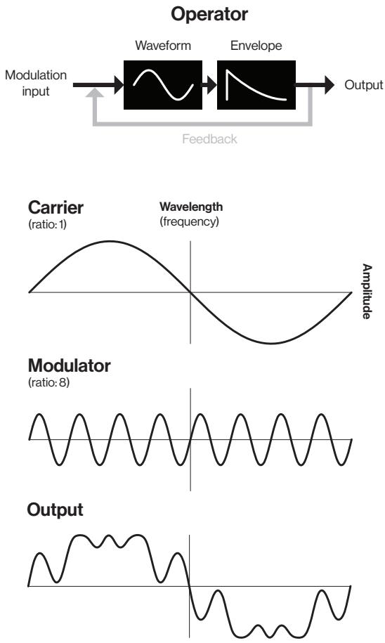
In some instances, an operator can be both carrier and modulator. This means that it outputs its result as a tone while also using it to modulate another operator. We have divided the operators into three groups: C, A, and B (B1 and B2) to lessen the complexity and make the Digitone easier to use. Since group B consist of two operators, the parameter controls for B are macro mapped to both operators.
A.3 ALGORITHMS
An algorithm is a set routing, or combination, of the operators. Routing the modulation in different ways gives you several different methods of applying modulation and naturally different results.

Pictured above is a 2 operator algorithm, which is FM synthesis in its most basic form. The Digitone has four operators available which can be routed in many different ways. Different algorithms dramatically changes the characteristics of the output - for example stacking four operators can lead to very complex timbres.
The Digitone has eight different algorithms where the four operators are routed in different ways. For more information, please see “11.3.1 ALGO” on page 47. Each algorithm has two carrier outputs (X and Y) that come from two different operators depending on what algorithm you chose. It is possible to use the MIX parameter to mix between these outputs so that you can cross-fade between two separate timbres. For more information, please see “11.3.8 MIX” on page 48.

The lines going to X and Y indicate the output from a carrier. There are two different ways a carrier output is sent to the X/Y outputs: 1. Its amplitude is unaffected by the operator envelope (dotted line). 2. Its amplitude is affected by the operator envelope (filled line). The sound from the X/Y outputs is then routed via the overdrive to the filters.
A.4 FM RATIOS
Frequency modulation is applied in multipliers of the principal frequency to retain the sounds tonality. These multipliers are known as ratios. Each operator group's ratio is a multiplier of the input pitch (note value). The higher the ratio, the higher the pitch frequency. For example, when applying modulation with a ratio of 1:2 (carrier:modulator), the carrier output resembles a square wave. A ratio of 1:1 sounds like a sawtooth, and odd numbers can be used for various metallic or other “natural” sounds. In Digitone, the FM ratios for the different operator groups works like this:
C which always works like a carrier, is limited mostly to integers since it is generally used for carrying the base note of the sound. For more information, please see “11.3.2 RATIO C” on page 47.
A has a more extensive number of ratio values to allow for more inharmonic relationships. For more information, please see “11.3.3 RATIO A” on page 47.
B (B1 and B2) controls both operators at the same time. The minimum value for B1 and B2 is .25. As you turn the encoder, B2 increases until it reaches the max (16). It then starts over from .25 and B1 increases to the next value (0.5). This revolving behavior continues until both operators reach the maximum value. This parameter behavior is similar to the movement of the hands on a watch. For more information, please see "11.3.4 RATIO B" on page 47.
A.5 THE OPERATOR ENVELOPES
If you modulate one oscillator directly with another it creates very harsh harmonics, so you need to limit the modulation level to control the amount of modulation. In Digitone you use an envelope and a LEVEL parameter control to attenuate the amount of how much the modulator affects the carrier. The envelopes also give the possibility to control the modulation over time. A piano for example, when first struck, the timbre is sharp but quickly fades to a softer tone. Envelopes and modulation level are vital elements in FM synthesis and are the tools that you use to shape the sounds you want to achieve.
The Digitone FM engine has two operator envelopes that are designed to be practical and easy to use. One envelope is for operator group A, and one is for group B (B1 and B2).
The envelopes are essentially expanded AD (Attack Decay) envelopes, but with an added adjustable end level (the amplitude level the sound reaches at the end of the decay stage). Normally, an AD envelope always ends at zero level, but with FM you often want to retain some modulation after a short pluck or fade in for example. For more information, please see “11.5 SYN 2 PAGE 1” on page 48.

Please note that operator envelope B controls the output from both B1 and B2.
The envelopes can be either triggered or gated - making it either an ADE (Attack Decay End) or an ASDE (Attack Sustain Decay End) envelope. The sustain phase does not have an envelope level. It is instead the LEV parameter that sets the sustain level. The note length defines the length of the sustain phase. For more information, please see “11.6.2 ATRG” on page 49.
Trigged (ATRG/BTRG ON)
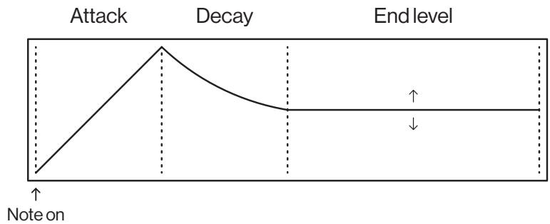
Gated (ATRG/BTRG OFF)

You can also set if the envelopes should reset or not when they are retrigged. For more information, please see "11.6.3 ARST" on page 50.
Reset on (ARST/BRST ON)

Reset off (ARST/BRST OFF)

The LEVEL parameters on the SYN2 page controls the amount of modulation from the A and B operators. For more information, please see “11.5.8 LEV B” on page 49. The LEVEL parameter for B is macro mapped to both operator B1 and B2 and control their modulation amount as per this graph:

A.6 HARMONICS
The default output from an operator is a sine wave, but you can use the HARM parameter to add upper partials to some of the operators' sine waves to create more harmonically rich waveforms. The HARM parameter is bipolar. Negative parameter values change the harmonics of operator C, while positive parameter values change the harmonics of operators A and B1.

When changing harmonics, intermediate values interpolates between the current and the next harmonic. This interpolation works much like in wavetable synthesis, sweeping between the harmonics, smoothly transitioning from one timbre to another. For more information, please see “11.3.5 HARM” on page 47. The harmonic series for the operators looks like this:

The Digitone uses a form of additive synthesis to create the harmonic series for the HARM parameter. Additive synthesis is one of the oldest forms of electronic sound generation. It is a quite simple form of synthesis but still very powerful. The basic principle is to add multiple sine waves together to form complex timbres. Each sine wave is called a partial. By attenuating each partial, the timbre changes its harmonic content, resulting in different waveforms.
The first partial is always kept at full volume, which keeps the base octave intact.

Adding every partial in series will replicate a sawtooth. Note how the volume decreases for each partial, creating a natural falloff.

Adding every odd partial in series will approximate a square wave.

The additive method can be used to make many different timbres. This combination of partials, for example, sounds close to a bell tone.

A.7 SYN1 PAGE 1 PARAMETERS OVERVIEW
Here is a graphical overview of what part of the FM engine the parameters on the SYN1 pages affects. The affected part of the FM engine is highlighted with grey. For more information, please see “11.3 SYN1 PAGE 1” on page 47.
Ratio C

Ratio A

Ratio B

Harm -

Harm +

Detune

Feedback

Mix

APPENDIX B: MIDI IMPLEMENTATION
This appendix lists the CC and NRPN specifications for the Digitone.
B.1 TRACK PARAMETERS
| TRACK | ||||
| Parameter | CC MSB | CC LSB | NRPN MSB | NRPN LSB |
| Mute | 94 | 1 | 101 | |
| Track level | 95 | 1 | 100 | |
B.2 TRIG PARAMETERS
| TRIG PARAMETERS | ||||
| Parameter | CC MSB | CC LSB | NRPN MSB | NRPN LSB |
| Root | 3 | 3 | 0 | |
| Velocity | 4 | 3 | 1 | |
| Length | 5 | 3 | 2 | |
| Filter Trig | 13 | 3 | 5 | |
| LFO Trig | 14 | 3 | 6 | |
| Portamento Time | 15 | 3 | 7 | |
| Portamento On | 16 | 3 | 8 | |
B.3 FM PARAMETERS
| SYN1 | ||||
| Parameter | CC MSB | CC LSB | NRPN MSB | NRPN LSB |
| Algorithm | 90 | 1 | 72 | |
| Ratio C | 91 | 1 | 73 | |
| Ratio A | 92 | 1 | 74 | |
| Ratio B | 16 | 48 | 1 | 75 |
| Harmonics | 17 | 49 | 1 | 76 |
| Detune | 18 | 50 | 1 | 77 |
| Feedback | 19 | 51 | 1 | 78 |
| Mix | 20 | 52 | 1 | 79 |
| Ratio C Offset | 1 | 95 | ||
| Ratio A Offset | 1 | 96 | ||
| Ratio B1 Offset | 1 | 97 | ||
| Ratio B2 Offset | 1 | 98 | ||
| SYN2 | ||||
| Parameter | CC MSB | CC LSB | NRPN MSB | NRPN LSB |
| A Env Attack | 75 | 1 | 80 | |
| A Env Decay | 76 | 1 | 81 | |
| A Env End | 77 | 1 | 82 | |
| A Level | 78 | 1 | 83 | |
| B Env Attack | 79 | 1 | 84 | |
| B Env Decay | 80 | 1 | 85 | |
| B Env End | 81 | 1 | 86 | |
| B Level | 82 | 1 | 87 | |
| A Delay | 83 | 1 | 88 | |
| A Trig | 84 | 1 | 89 | |
| A Env Reset | 85 | 1 | 90 | |
| B Delay | 86 | 1 | 91 | |
| B Trig | 87 | 1 | 92 | |
| B Env Reset | 88 | 1 | 93 | |
| Phase Reset | 89 | 1 | 94 | |
B.4 FILTER PARAMETERS
| FILTER | ||||
| Parameter | CC MSB | CC LSB | NRPN MSB | NRPN LSB |
| Filter Frequency | 23 | 55 | 1 | 20 |
| Resonance | 24 | 56 | 1 | 21 |
| Filter Type | 74 | 1 | 22 | |
| Attack Time | 70 | 1 | 16 | |
| Decay Time | 71 | 1 | 17 | |
| Sustain Level | 72 | 1 | 18 | |
| Release Time | 73 | 1 | 19 | |
| Env. Depth | 25 | 57 | 1 | 23 |
| Env. Delay | 43 | 1 | 66 | |
| Base | 26 | 58 | 1 | 24 |
| Width | 27 | 59 | 1 | 25 |
B.5 AMP PARAMETERS
| AMP | ||||
| Parameter | CC MSB | CC LSB | NRPN MSB | NRPN LSB |
| Attack Time | 104 | 1 | 32 | |
| Decay Time | 105 | 1 | 33 | |
| Sustain Level | 106 | 1 | 34 | |
| Release Time | 107 | 1 | 35 | |
| Drive | 9 | 41 | 1 | 36 |
| Pan | 10 | 42 | 1 | 37 |
| Volume | 7 | 39 | 1 | 38 |
| Chorus Send | 12 | 44 | 1 | 41 |
| Delay Send | 13 | 45 | 1 | 40 |
| Reverb Send | 14 | 46 | 1 | 39 |
| Amp Env Reset | 102 | 1 | 42 | |
B.6 LFO PARAMETERS
| LFO | ||||
| Parameter | CC MSB | CC LSB | NRPN MSB | NRPN LSB |
| Speed LFO1 | 28 | 60 | 1 | 48 |
| Multiplier LFO1 | 108 | 1 | 49 | |
| Fade In/Out LFO1 | 109 | 1 | 50 | |
| Destination LFO1 | 110 | 1 | 51 | |
| Waveform LFO1 | 111 | 1 | 52 | |
| Start Phase LFO1 | 112 | 1 | 53 | |
| Trig Mode LFO1 | 113 | 1 | 54 | |
| Depth LFO1 | 29 | 61 | 1 | 55 |
| Speed LFO2 | 30 | 62 | 1 | 57 |
| Multiplier LFO2 | 114 | 1 | 58 | |
| Fade In/Out LFO2 | 115 | 1 | 59 | |
| Destination LFO2 | 116 | 1 | 60 | |
| Waveform LFO2 | 117 | 1 | 61 | |
| Start Phase LFO2 | 118 | 1 | 62 | |
| Trig Mode LFO2 | 119 | 1 | 63 | |
| Depth LFO2 | 31 | 63 | 1 | 64 |
B.7 MIDI TRACK PARAMETERS
| CC VALUE | ||||
| Parameter | CC MSB | CC LSB | NRPN MSB | NRPN LSB |
| CC Val1 | 70 | |||
| CC Val2 | 71 | |||
| CC Val3 | 72 | |||
| CC Val4 | 73 | |||
| CC Val5 | 74 | |||
| CC Val6 | 75 | |||
| CC Val7 | 76 | |||
| CC Val8 | 77 | |||
B.8 FX PARAMETERS
| CHORUS | ||||
| Parameter | CC MSB | CC LSB | NRPN MSB | NRPN LSB |
| Depth | 3 | 35 | 2 | 0 |
| Speed | 9 | 41 | 2 | 1 |
| High-pass | 70 | 2 | 2 | |
| Width | 71 | 2 | 3 | |
| Delay Send | 12 | 44 | 2 | 4 |
| Reverb Send | 13 | 45 | 2 | 5 |
| Mix Volume | 14 | 2 | 6 | |
| DELAY | ||||
| Parameter | CC MSB | CC LSB | NRPN MSB | NRPN LSB |
| Delay Time | 15 | 47 | 2 | 10 |
| Pingpong | 16 | 48 | 2 | 11 |
| Stereo Width | 17 | 49 | 2 | 12 |
| Feedback | 18 | 50 | 2 | 13 |
| Highpass Filter | 72 | 2 | 14 | |
| Lowpass Filter | 73 | 2 | 15 | |
| Reverb Send | 19 | 51 | 2 | 16 |
| Mix Volume | 20 | 2 | 17 | |
| REVERB | ||||
| Parameter | CC MSB | CC LSB | NRPN MSB | NRPN LSB |
| Predelay | 21 | 53 | 2 | 20 |
| Decay Time | 74 | 2 | 21 | |
| Shelving Freq | 75 | 2 | 22 | |
| Shelving Gain | 22 | 54 | 2 | 23 |
| Highpass Filter | 76 | 2 | 24 | |
| Lowpass Filter | 77 | 2 | 25 | |
| Mix Volume | 23 | 2 | 26 | |
| MASTER | ||||
| Parameter | CC MSB | CC LSB | NRPN MSB | NRPN LSB |
| Master Overdrive | 29 | 61 | 2 | 37 |
| Dual Mono | 83 | 2 | 105 | |
| Input L Volume | 24 | 56 | 2 | 30 |
| Input R Volume | 25 | 57 | 2 | 32 |
| Pan L | 78 | 2 | 31 | |
| Pan R | 79 | 2 | 33 | |
| Chorus Send L | 26 | 58 | 2 | 34 |
| Chorus Send R | 30 | 62 | 2 | 102 |
| Delay Send L | 27 | 59 | 2 | 35 |
| Delay Send R | 31 | 63 | 2 | 103 |
| Reverb Send L | 28 | 60 | 2 | 36 |
| Reverb Send R | 82 | 32 | 2 | 104 |
| Chorus Send L/R | 26 | 58 | 2 | 34 |
| Delay Send L/R | 27 | 59 | 2 | 35 |
| Reverb Send L/R | 28 | 60 | 2 | 36 |
| Master Overdrive | 29 | 61 | 2 | 37 |
| Pattern Volume | 95 | 2 | 38 | |
B.9 MISC PARAMETERS
| MISC | ||||
| Parameter | CC MSB | CC LSB | NRPN MSB | NRPN LSB |
| Pattern Mute | 1 | 104 | ||
| Sustain | 64 | |||
| Sostenuto | 66 | |||
APPENDIX C: LFO MODULATION DESTINATIONS
The following are the modulation destinations for the Digitone's LFOs:
AUDIO TRACKS
| SYN: Algorithm | AMPLIFIER: Attack Time |
| SYN: Ratio C | AMPLIFIER: Decay Time |
| SYN: Ratio A | AMPLIFIER: Sustain Level |
| SYN: Ratio B | AMPLIFIER: Release Time |
| SYN: Harmonics | AMPLIFIER: Drive |
| SYN: Detune | AMPLIFIER: Pan |
| SYN: Feedback | AMPLIFIER: Volume |
| SYN: Mix | AMPLIFIER: Reverb Send |
| SYN: A Attack | AMPLIFIER: Delay Send |
| SYN: A Decay | AMPLIFIER: Chorus Send |
SYN: A End
SYN: A Level
SYN: B Attack
SYN: B Decay
SYN: B End
SYN: B Level
SYN: A Delay
SYN: B Delay
SYN: Pitch All
SYN: Pitch A and B2
SYN: Ratio All
SYN: AB Level
SYN: AB Attack
SYN: AB Decay
SYN: AB End
SYN: AB Delay
SYN: Ratio C Offset
SYN: Ratio A Offset
SYN: Ratio B1 Offset
SYN: Ratio B2 Offset
FILTER: Frequency
FILTER: Resonance
FILTER: Envelope Depth
FILTER: Attack Time
FILTER: Decay Time
FILTER: Sustain Level
FILTER: Release Time
FILTER: Base
FILTER: Width
FILTER: Env. Delay
AMPLIFIER: Attack Time
MIDI TRACKS
SRC: Pitch Bend
SRC: Aftertouch
SRC: Mod Wheel
SRC: Breath Controller
CC: CC1 Value
CC: CC2 Value
CC: CC3 Value
CC: CC4 Value
CC: CC5 Value
CC: CC6 Value
CC: CC7 Value
CC: CC8 Value
APPENDIX D: KEYBOARD SCALES
The following are the selectable scales for the KEYBOARD mode. For more information, please see: "8.5.2 KEYBOARD SETUP MENU" on page 23,
- CHROMATIC
• IONIAN (MAJOR)
• DORIAN - PHRYGIAN
• LYDIAN - MIXOLYDIAN
• AEOLIAN (MINOR) - LOCRIAN
• PENTATONIC MINOR
• PENTATONIC MAJOR - MELODIC MINOR
• HARMONIC MINOR - WHOLE TONE
- BLUES
- COMBO MINOR
- PERSIAN
- IWATO
• IN-SEN - HIRAJOSHI
- PELOG
• PHRYGIAN DOMINANT
• WHOLE-HALF DIMINISHED
• HALF-WHOLE DIMINISHED - SPANISH
- MAJOR LOCRIAN
- SUPER LOCRIAN
• DORIAN b2
• LYDIAN AUGMENTED
• LYDIAN DOMINANT
• DOUBLE HARMONIC MAJOR - LYDIAN #2 #6
- ULTRAPHRYGIAN
• HUNGARIAN MINOR - ORIENTAL
- IONIAN #2 #5
- LOCRIAN bb3 bb7
INDEX
+DRIVE 16, 27
A
AFTERTOUCH 31
ARPEGGIATOR 31
AUDIO ROUTING
Global 74, 75
Pattern 67
B
BACKUP 20
BREATH CONTROLLER 31
C
CHAINS 43
CHORUS 60
CLASS COMPLIANT 20
CONDITIONAL LOCKS 40
CONNECTORS 14
COPY, PASTE AND CLEAR 42
CREDITS AND CONTACT INFORMATION 88
D
DATA STRUCTURE 16
Patterns 16
Project 16
Sounds 16
DELAY 60
F
FACTORY RESET 81
FILL MODE 41
FILTER 51
FM SYNTHESIS
Algorithms 90
Carrier 89
FM ratios 90
Harmonics 92
Modulator 89
Operator envelopes 91
Operators 89
SYN1 Page 1 parameters overview 93
FX PARAMETERS 60
Chorus 60
Delay 60
Master 62, 63
Reverb 60, 62, 63
G
GRID RECORDING MODE 33
Quick note method 34
Track note method 33
K
KEYBOARD MODE 24
KEYBOARD SCALES 100
KEY COMBINATIONS 85
KEY SCALING 28
L
LED INTENSITY 79
LFO 54, 58
Modulation destinations 99
LIVE RECORDING MODE 34
M
MASTER TUNE 80
MICRO TIMING 38
MIDI CONFIG 65, 70
MIDI IMPLEMENTATION 95
MIDI TRACK PARAMETERS 56
Amp (CC select) 58
Filter (CC value) 57
LFO 58
MIDI Source 54, 56, 57
Trig 56
MOD WHEEL 30
MULTI MAP 75
External trig 78
Internal trig 77
Pattern play 77
Ranges 76
MUTE MODE 25
N
NAMING SCREEN 19
0
OS UPGRADE 79
OVERBRIDGE 20
USB config 78, 79
OVERDRIVE 53
P
PANEL LAYOUT 12
PARAMETER LOCKS 39
PATTERNS
Parameter locks 39
Pattern control 32
Selecting a pattern 32
Tempo 32
Trig Types 33
PATTERNS AND SOUNDS 27
Editing a sound 27
Playing a sound 27
Sound Browser 68
Sound Manager 69
PITCH BEND 30
PORTAMENTO
On/Off 47
Settings 29, 30
Time 47
PROJECT MANAGER 65
PROJECTS 65
Load 65
Project Manager 65
Save 65
Write protection 65
Q
QUANTIZE 66
QUICK SCROLLING 19
QUICK START 22
R
RANDOMIZE
Parameters 46
REVERB 62
S
SAFETY AND MAINTENANCE 3
SCALE 36
SCALES 100
SCALE SETUP
Length per pattern mode 38
Length per track mode 39
SCREEN SAVER 18
SEQUENCER 32
Conditional locks 40
Editing a pattern 32
Metronome 38
Micro timing 38
Parameter locks 39
Pattern control 32
Scale Menu 38
Selecting a pattern 32
Swing 41
Trig parameters page 36
SEQUENCER RECORDING MODES
Grid recording mode 33
Grid recording using Quick Note method 34
Grid recording using Track Note method 33
Live recording mode 34
Step recording mode 35
SETTINGS
MIDI config 65
SETTINGS MENU 65
MIDI config 70
Project 65
System 78
SETUP EXAMPLES 20, 82
Controlling a synthesizer using the MIDI tracks 83
Digitone together with the Digitakt 82
Digitone with a monophonic bass machine 82
SONG MODE 43
SOUND ARCHITECTURE 15
SOUND BROWSER 68
SOUND LOCKS 40
SOUND MANAGER 69
SOUND MENU 68
SOUNDS
Clear Sound 70
Editing a Sound 27
Playing a Sound 27
Rename a Sound 70
Saving a Sound 28
Synth track parameters 46
SOUND SETUP MENU 28
Aftertouch 31
Breath controller 31
Filter keyscaling 29
Keyscaling 28
Mod wheel 30
Octave 30
Pitch bend 30
Pitch bend depth 30
Velocity mod 30
Velocity to vol 30
STARTUP MENU 81
STEP RECORDING MODE 35
SWING 41
SYNTH TRACK PARAMETERS 46
Amp 52
Filter 51
LFO 54
SYN 47, 48
Trig 46
SYSEX DUMP 73
T
TECHNICAL INFORMATION 88
TEMPO 22
TEMPORARY SAVE AND RELOAD 42
TRACK NOTE MENU 36
TRANSPOSE
Direct pattern transpose 43
Direct track transpose 42
Transpose track 25
TRIG PARAMETERS PAGE 36
TRIGS 33
Lock trigs 33
Note trigs 33
Parameter locks 39
Sound lock 40
U
UNISON 37
V
VELOCITY
Set fixed value 78
VOICE MENU 37
Layer 37
Locked voices 37
Unison 37
Unison Spread 37
Voice stealing 37



- DIGITONE
- FCC COMPLIANCE STATEMENT
- CANADA
- EUROPEAN UNION REGULATION COMPLIANCE STATEMENT
- LEGAL DISCLAIMER
- IMPORTANT SAFETY AND MAINTENANCE INSTRUCTIONS
- WARNING
- SAFETY INSTRUCTIONS FOR THE POWER ADAPTER
- RESTART
- TABLE OF CONTENTS
- INTRODUCTION
- THE DIGITONE
- PANEL LAYOUT AND CONNECTORS
- DIGITONE SOUND ARCHITECTURE
- OVERVIEW OF THE DIGITONE DATA STRUCTURE
- ABOUT THE TRACKS
- INTERACTING WITH THE DIGITONE
- THE NAMING SCREEN
- QUICK START
- DIGITONE CONTROLS
- PATTERNS AND SOUNDS
- THE SEQUENCER
- METRONOME MENU
- SCALE MENU
- SEQUENCER FEATURES
- CHAINS
- SONG MODE
- SYNTH TRACK PARAMETERS
- EDITING THE SYNTH TRACK PARAMETERS
- TRIG PARAMETERS PAGE
- MIDI TRACK PARAMETERS
- FX PARAMETERS
- SETTINGS MENU
- PROJECT
- SONG
- PATTERN
- SOUNDS
- MIDI CONFIG
- SYSEX DUMP
- AUDIO ROUTING (GLOBAL)
- GLOBAL FX/MIX
- CONTROL
- SYSTEM
- STARTUP MENU
- TEST MODE
- EMPTY RESET
- FACTORY RESET
- OS UPGRADE
- CONVENTIONS IN THIS MANUAL
- REAR CONNECTORS
- SETTING UP AND STARTING THE DIGITONE
- AUDIO VOICES
- EFFECTS
- DRIVE
- DATA STRUCTURE
- PATTERNS
- THE SYNTH TRACKS
- THE MIDI TRACKS
- EDITING THE TRACKS
- SCREEN NAVIGATION
- PARAMETER EDITING
- PARAMETER VALUE JUMP
- CONTROL ALL
- [FUNC] KEY PRESS COMBINATIONS
- QUICK SCROLLING
- COPY, CLEAR, AND PASTE
- NAMING POP-UP MENU
- OVERBRIDGE
- CLASS COMPLIANT DEVICE
- BACKING UP THE DIGITONE
- BACKING UP PROJECTS AND SOUNDS
- TRANSFERRING BACKED UP FILES TO YOUR ELEKTRON DEVICE
- PLAYING THE FACTORY PRESET PATTERNS
- USING THE TRIG KEYS TO PLAY THE DIGITONE
- CHANGING SOUNDS
- USING MUTE MODE
- TEMPO
- EDITING PARAMETERS
- TRIG KEYS
- ROTARY ENCODERS
- KEY BEHAVIOR
- MIDI NOTES
- MODES
- KEYBOARD MODE
- KEYBOARD SETUP MENU
- MUTE MODE
- A PATTERN CONTAINS
- A SOUND CONTAINS
- THE +DRIVE SOUND LIBRARY AND THE SOUND POOL
- ADDING SOUNDS TO THE SOUND POOL
- PLAYING A SOUND
- PLAYING A SOUND WITH AN EXTERNAL MIDI UNIT
- EDITING A SOUND
- SAVING A SOUND
- SAVING A SOUND TO THE +DRIVE
- SAVING A SOUND TO THE SOUND POOL
- SOUND SETUP MENU
- KEY SCALING A
- KEY SCALING B
- FILTER KEYTRACK
- PORTAMENTO
- TYPE
- SLOPE
- AMOUNT
- STYLE
- GATING
- PLAY MODE
- MONO NOTE PRIO
- VELOCITY TO VOL
- PITCH BEND DEPTH
- OCTAVE
- PITCH BEND
- VELOCITY MOD
- MOD WHEEL
- BREATH CONTROLLER
- AFTERTOUCH
- ARPEGGIATOR MENU
- MODE
- SPD
- RNG
- LEN
- ARP LENGTH
- OFFSET
- BASIC PATTERN OPERATIONS
- SELECTING BANK AND PATTERN
- PATTERN CONTROL
- PATTERN TEMPO
- CREATING AND EDITING A PATTERN
- TRIG TYPES
- GRID RECORDING MODE
- GRID RECORDING USING TRACK NOTE METHOD
- GRID RECORDING USING QUICK NOTE METHOD
- LIVE RECORDING MODE
- STEP RECORDING MODE
- STANDARD MODE
- JUMP MODE
- TRIG PARAMETERS
- TRACK NOTE MENU
- VOICE MENU
- MICRO TIMING MENU
- LENGTH PER PATTERN MODE
- LENGTH PER TRACK MODE
- PARAMETER LOCKS
- SOUND LOCKS
- TRIG CONDITIONS AND CONDITIONAL LOCKS
- ADDING A CONDITIONAL LOCK
- FOR EXAMPLE
- FILL MODE
- SWING
- COPY, PASTE AND CLEAR OPERATIONS
- TEMPORARY SAVE AND RELOAD PATTERN COMMANDS
- DIRECT TRACK TRANSPOSE
- DIRECT PATTERN TRANSPOSE
- CREATING A CHAIN
- THE SONG EDIT SCREEN
- CREATING AND EDITING A SONG
- PLAYING A SONG
- ROOT
- VEL
- PROB
- FLT.T
- LFO.T
- PTIM
- PORT
- SYN1 PAGE
- ALGO
- RATIO C
- RATIO A
- RATIO B
- HARM
- DTUN
- FDBK
- MIX
- RATIO OFFSET C, A, B1, B
- SYN 2 PAGE
- ATK A
- DEC A
- END A
- LEV A
- ATK B
- DEC B
- END B
- LEV B
- SYN2 PAGE
- ADEL
- ATRG
- ARST
- PHRT
- BDEL
- BTRG
- BRST
- FLTR PAGE
- ATK
- DEC
- SUS
- REL
- FREQ
- RESO
- ENV
- DEL
- BASE
- WIDTH
- AMP PAGE
- DRV
- PAN
- VOL
- CHR
- REV
- AENR
- LFO PAGE
- MULT
- FADE
- DEST
- WAVE
- SPH
- DEP
- EDITING THE MIDI TRACK PARAMETERS
- SYN1 PAGE (MIDI SOURCE)
- CHAN
- BANK
- SBNK
- PROG
- PB
- AT
- MW
- BC
- SYN2 PAGE (MIDI SOURCE)
- FLTR PAGE (CC VALUE)
- VAL1-VAL
- AMP PAGE (CC SELECT)
- SEL1-SEL
- EDITING THE FX PARAMETERS
- CHORUS
- DPTH
- HPF
- WDTH
- DELAY
- TIME
- X
- WID
- LPF
- REVERB
- PRE
- GAIN
- INTERNAL MIXER (MASTER PAGE 1)
- MOVD
- TRK
- PVOL
- EXT-IN MIXER L (MASTER PAGE 2)
- IN L
- LPAN
- DUAL
- LCHR
- LDEL
- LREV
- EXT-IN MIXER R (MASTER PAGE 3)
- IN R
- RPAN
- RCHR
- RDEL
- RREV
- LOAD PROJECT
- SAVE PROJECT AS
- MANAGE PROJECTS
- RENAME
- CLEAR
- LOAD
- SAVE TO PROJ
- QUANTIZE
- RELOAD FROM PROJ
- IMPORT/EXPORT
- AUDIO ROUTING (PATTERN)
- SOUND BROWSER
- SOUND MANAGER
- CLEAR TRACK SOUND
- RENAME TRACK SOUND
- SETUP
- SYNC
- PORT CONFIG
- CHANNELS
- SYSEX SEND
- SYSEX RECEIVE
- ROUTE TO MAIN
- SEND TO FX
- INT TO MAIN
- USB TO MAIN
- MULTI MAP EDIT
- MULTI MAP MENU
- RANGE OPERATIONS MENU
- RANGE EDIT MENU
- USB CONFIG
- LED BACKLIGHT
- LED INTENSITY
- REMEMBER SUBPAGE
- FORMAT +DRIVE
- MASTER TUNE
- EXIT
- SETUP EXAMPLES
- DIGITONE WITH A MONOPHONIC BASS MACHINE
- DIGITONE TOGETHER WITH THE DIGITAKT
- CONTROLLING A SYNTHESIZER USING THE MIDI TRACKS
- USEFUL KEY COMBINATIONS
- GENERAL
- TRACK/BANK/PATTERN SELECT
- NAMING
- SAVING AND RELOADING
- MENU ACCESS
- SEQUENCER SETTINGS
- SEQUENCER RECORDING
- MUTES
- UNISON
- CLEAR TRACK/CLEAR PATTERN
- RESET PARAMETERS
- RANDOMIZE PARAMETERS
- ARPEGGIATOR
- SOUND PREVIEW
- TECHNICAL INFORMATION
- ELECTRICAL SPECIFICATIONS
- HARDWARE
- PHYSICAL SPECIFICATIONS
- CREDITS AND CONTACT INFORMATION
- CREDITS
- PRODUCT DESIGN AND DEVELOPMENT
- ADDITIONAL DESIGN
- DOCUMENTATION
- PRESET SOUND DESIGN
- CONTACT INFORMATION
- ELEKTRON WEBSITE
- OFFICE ADDRESS
- APPENDIX A: THE DIGITONE FM SYNTHESIS
- A.1 OVERVIEW
- A.2 THE OPERATORS
- A.3 ALGORITHMS
- A.4 FM RATIOS
- A.5 THE OPERATOR ENVELOPES
- PLEASE NOTE THAT OPERATOR ENVELOPE B CONTROLS THE OUTPUT FROM BOTH B1 AND B
- A.6 HARMONICS
- A.7 SYN1 PAGE 1 PARAMETERS OVERVIEW
- APPENDIX B: MIDI IMPLEMENTATION
- B.7 MIDI TRACK PARAMETERS
- B.8 FX PARAMETERS
- APPENDIX C: LFO MODULATION DESTINATIONS
- APPENDIX D: KEYBOARD SCALES
- INDEX
- A
- B
- C
- D
- F
- G
- K
- L
- M
- N
- P
- PROJECT MANAGER
- PROJECTS
- Q
- R
- RANDOMIZE
- S
- SAFETY AND MAINTENANCE
- SCALE
- SCALES
- SCALE SETUP
- SCREEN SAVER
- SEQUENCER
- SEQUENCER RECORDING MODES
- SETTINGS
- SOUND ARCHITECTURE
- SOUND MENU
- T
- TEMPORARY SAVE AND RELOAD
- TRANSPOSE
- TRIGS
Brand : Elektron
Model : Digitone
Category : Electronic musical instrument