
Analog Heat +FX - Electronic musical instrument Elektron - Free user manual and instructions
Find the device manual for free Analog Heat +FX Elektron in PDF.


| Product Type | Electronic musical instrument, analog stereo distortion and effects unit |
| Dimensions | 215 x 184 x 63 mm (8.5" x 7.2" x 2.5") |
| Weight | Approximately 1.5 kg (3.3 lbs) |
| Power Supply | 12 V DC, 2A, using included PSU-3/b/c adapter |
| Power Consumption | 12 W typical |
| Display | 128x64 pixel OLED screen |
| Audio Converters | 48 kHz, 24-bit D/A and A/D converters |
| Audio Inputs | 2x 1/4" balanced audio input jacks (L/R) |
| Audio Outputs | 2x 1/4" impedance balanced audio output jacks (L/R) |
| Headphone Output | 1x 1/4" stereo headphone jack |
| Control Inputs | 2x 1/4" jacks for CV, expression pedal, or footswitch |
| MIDI Connectivity | MIDI In/Out/Thru with DIN sync out |
| USB Port | Electrically isolated Hi-speed USB 2.0 port |
| Analog Effects | 8 drive/distortion circuits, analog filter with 7 types, 2-band EQ |
| Digital Effects | Bits, warble, compressor, bass focus, chorus, delay, reverb |
| Presets | 512 preset slots divided into four banks (A-D) |
| Overbridge Support | Plugin integration (VST/AU/AAX) for DAW control and total recall |
| Class Compliant | Plug-and-play with Windows, macOS, and iOS devices |
| Mounting | VESA 100x100 mm mounting holes (M4 screws, max length 7.4 mm) |
| Casing | Sturdy steel casing |
| Maintenance | Clean with a soft, dry, non-abrasive cloth; disconnect all cables first |
| Cleaning | Use a slightly damp cloth with water for persistent dirt; never use aggressive cleaners |
| Safety | Do not expose to rain or moisture; do not open casing; keep away from heat sources |
| Repairability | No user-repairable parts inside; refer all servicing to qualified technicians |
| Operating Temperature | Maximum ambient operating temperature +35°C (+96°F) |
Frequently Asked Questions - Analog Heat +FX Elektron
User questions about Analog Heat +FX Elektron
0 question about this device. Answer the ones you know or ask your own.
Ask a new question about this device
Download the instructions for your Electronic musical instrument in PDF format for free! Find your manual Analog Heat +FX - Elektron and take your electronic device back in hand. On this page are published all the documents necessary for the use of your device. Analog Heat +FX by Elektron.
USER MANUAL Analog Heat +FX Elektron
Analog Heat +FX
User Manual
FCC compliance statement
This device complies with part 15 of the FCC rules. Operation is subject to the following two conditions: (1) This device may not cause harmful interference, and (2) this device must accept any interference received, including interference that may cause undesired operation.
NOTE: This equipment has been tested and found to comply with the limits for a Class B digital device, pursuant to Part 15 of the FCC Rules. These limits are designed to provide reasonable protection against harmful interference in a residential installation. This equipment generates, uses and can radiate radio frequency energy and, if not installed and used in accordance with the instructions, may cause harmful interference to radio communications. However, there is no guarantee that interference will not occur in a particular installation. If this equipment does cause harmful interference to radio or television reception, which can be determined by turning the equipment off and on, the user is encouraged to try to correct the interference by one or more of the following measures:
- Reorient or relocate the receiving antenna.
- Increase the separation between the equipment and receiver.
- Connect the equipment into an outlet on a circuit different from that to which the receiver is connected.
- Consult the dealer or an experienced radio/TV technician for help.
Canada
This Class B digital apparatus complies with Canadian ICES-003.
Cet appareil numérique de la classe B est conforme à la norme NMB-003
European Union regulation compliance statement
This product has been tested to comply with the Low Voltage Directive 2014/35/EU and the Electromagnetic Compatibility Directive 2014/30/EU. The product meets the requirements of RoHS 2 Directive 2011/65/EU.

This symbol indicates that your product must be disposed of properly according to local laws and regulations.
Legal disclaimer
The information in this document is subject to change without notice and should not be construed as a commitment by Elektron. Elektron assumes no responsibility for any errors that may appear in this document. Elektron may also make improvements and/or changes in the products and programs described in this document at any time without notice. In no event shall Elektron be liable for any special, indirect, or consequential damages or any damages whatsoever resulting from loss of use, data, or profits, whether in an action of contract, negligence, or other action, arising out of or in connection with the use or performance of this information.
IMPORTANT SAFETY AND MAINTENANCE INSTRUCTIONS
Please read these instructions carefully and follow the operating advice given here.
- Do not use this unit near water.
- Never use aggressive cleaners on the casing or the screen. Remove dust, dirt and fingerprints with a soft, dry and non-abrasive cloth. More persistent dirt can be removed with a slightly damp cloth using only water. Disconnect all cables before doing this. Only reconnect them when the product is safely dry.
- Install by following the manufacturer's instructions. Make sure you place the unit on a stable surface before use.
-
Connect the unit to an easily accessible electrical outlet close to the unit.
-
When transporting the unit, use accessories recommended by the manufacturer or the original box and padding.
-
Do not install near any heat sources such as radiators, heat registers, stoves, or any other equipment (including amplifiers) producing heat.
-
Do not block the ventilation holes located on the bottom of the enclosure of the unit. Make sure there is sufficient air circulation in the room where the unit is kept.
-
This product, in combination with an amplifier and speakers or headphones, is capable of producing sound levels that can cause permanent hearing loss. Do not operate for extended periods of time at a high volume level or at a level that is uncomfortable.
-
Protect the power cord from being walked on or pinched particularly at plugs, convenience receptacles, and the point where they exit from the unit.
-
Use attachments/accessories specified by the manufacturer.
-
Unplug this unit during lightning storms or when it is not used for extended periods of time.
-
Refer all servicing to qualified service technicians. Servicing is required when the unit has been damaged in any way, liquid has been spilled or objects have fallen into the unit, the unit has been exposed to rain or moisture, does not operate normally, or has been dropped.
WARNING
To reduce the risk of fire, electrical shock or product damage:
- Do not expose the unit to rain, moisture, dripping or splashing and also avoid placing objects filled with liquid, such as vases, on the unit.
- Do not expose the unit to direct sunlight, nor use it in ambient temperatures exceeding 35° C as this can lead to malfunction.
- Do not open the casing. There are no user repairable or adjustable parts inside. Leave service and repairs to trained service technicians only.
- Do not exceed the limitations specified in the Electrical specifications.
SAFETY INSTRUCTIONS FOR THE POWER ADAPTER
- The adapter is not safety grounded and may only be used indoors.
- To ensure sufficient ventilation for the adapter, do not place it in tight spaces. To prevent the risk of electric shock and fire because of overheating, ensure that curtains and other objects do not prevent adapter ventilation.
- Do not expose the power adapter to direct sunlight, nor use it in ambient temperatures exceeding 40°C .
- Connect the adapter to an easily accessible electrical outlet close to the unit.
- The adapter is in standby mode when the power cord is connected. The primary circuit is always active as long as the cord is attached to the power outlet. Pull out the power cord to completely disconnect the adapter.
• In the EU, only use CE approved power cords.
TABLE OF CONTENTS
1. INTRODUCTION....7
1.1 CONVENTIONS IN THIS MANUAL 7
2. PANEL LAYOUT AND CONNECTIONS .... 8
2.1 FRONT PANEL CONTROLS 8
2.2 REAR PANEL CONNECTIONS 9
3. FIRST STEPS WITH THE ANALOG HEAT +FX.... 10
3.1 CONNECTING THE UNIT.... 10
3.2 SETTING THE INPUT SENSITIVITY LEVEL 10
3.3 SETUP EXAMPLES ...... 10
3.3.1 ANALOG HEAT +FX AS AN EXTERNAL EFFECT....11
3.3.2 ANALOG HEAT +FX AS A VST/AU/AAX PLUGIN USING OVERBRIDGE .....11
3.3.3 ANALOG HEAT +FX AS A SOUND CARD .....11
4. SIGNAL FLOW.... 12
4.1 AUDIO SIGNAL FLOW 12
4.2 MODULATION SIGNAL FLOW 12
5. INTERACTING WITH THE ANALOG HEAT +FX.... 13
5.1 PRESETS ...... 13
5.1.1 LOADING A PRESET 13
5.1.2 SAVING A PRESET 13
5.2 ACTIVE.... 13
5.3 EFFECT CIRCUITS.... 13
5.4 FILTER TYPES.... 14
5.5 EQUALIZER 14
5.6 DRIVE....14
5.7 LEVEL....14
5.8 MIX 14
5.9 SETTINGS MENU 14
5.10 PARAMETER PAGES.... 14
5.11 PARAMETER EDITING.... 14
5.12 SCREEN INFORMATION.... 15
5.13 TEMPO 15
5.14 OVERBRIDGE.... 15
5.15 CLASS COMPLIANT DEVICE.... 16
5.16 BACKING UP THE ANALOG HEAT +FX 16
5.16.1 BACKING UP PRESETS 16
5.16.2 TRANSFERRING BACKED UP FILES TO YOUR ELEKTRON DEVICE.... 16
6. THE SETTINGS MENU....17
6.1 PRESET CONFIG.... 17
6.1.1 ANALOG MODE 17
6.1.2 VOLUME.... 17
6.1.3 OUTPUT GAIN 17
6.2 INPUT SENSITIVITY 17
6.3 OPTIONS.... 18
6.3.1 PAGE MENU 18
6.3.2 FX PAGE ORDER 18
6.3.3 MOMENTARY ACTIVE 18
6.3.4 ACTIVE AT START 18
6.3.5 KNOB MODE 18
6.4 CONTROL IN 18
6.4.1 CONTROL IN A....18
6.4.2 CONTROL IN B....19
6.5 AUDIO ROUTING.... 19
6.5.1 ANALOG IN/OUT (IN OVERBRIDGE MODE) 19
6.5.2 ANALOG IN/OUT (IN USB AUDIO/MIDI MODE)....20
6.5.3 USB CC MODE 20
6.5.4 USB TO MAIN 21
6.5.5 FX TO USB 21
6.6 MIDI CONFIG 21
6.6.1 SYNC 21
6.6.2 PORT CONFIG 21
6.6.3 CHANNELS 22
6.7 SYSEX DUMP 22
6.7.1 SYSEX SEND....23
6.7.2 SYSEX RECEIVE....23
6.8 SYSTEM....23
6.8.1 USB CONFIG....23
6.8.2 OS UPGRADE 24
6.8.3 CALIBRATION....24
7. PARAMETER PAGES....25
7.1 FLOW 25
7.1.1 CHANGING THE ORDER OF THE FX BLOCKS 25
7.1.2 SETTING THE DRY/WET MIX OF THE FX BLOCKS 25
7.1.3 BYPASSING/ACTIVATING AN FX BLOCK 26
7.2 HEAT....26
7.2.1 AMP 26
7.2.2 FILTER 1/2 ...... 26
7.2.3 FILTER 2/2 ...... 27
7.2.4 GATE....27
7.3 FX....28
7.3.1 BITS 28
7.3.2 WARBLE PAGE 1....28
7.3.3 WARBLE PAGE 2 ...... 28
7.3.4 COMPRESSOR PAGE 1....28
7.3.5 COMPRESSOR PAGE 2....29
7.3.6 BASS FOCUS....29
7.3.7 CHORUS .... 30
7.3.8 DELAY PAGE 1....30
7.3.9 DELAY PAGE 2....31
7.3.10 REVERB PAGE 1....32
7.3.11 REVERB PAGE 2....32
7.4 MOD....33
7.4.1 ENV PAGE 1....33
7.4.2 ENV PAGE 2....34
7.4.3 LFO1 PAGE 1....35
7.4.4 LFO1 PAGE 2 ....36
7.4.5 LFO2 PAGE 1 ....36
7.4.6 LFO2 PAGE 2....36
7.4.7 LFO3 PAGE 1 ....36
7.4.8 LFO3 PAGE 2....37
7.4.9 MATRIX 37
8. TIPS & TRICKS ....38
8.1 ADDING SATURATION TO THE HIGH REGISTER....38
8.2 ANALOG PSEUDO-COMPRESSION....38
8.3 STEREO PHASER EFFECT ...... 39
9. STARTUP MENU ....40
9.1 TEST MODE....40
9.2 EMPTY RESET....40
9.3 FACTORY RESET .... 40
9.4 OS UPGRADE....40
10. TECHNICAL INFORMATION 41
11. CREDITS AND CONTACT INFORMATION.... 41
APPENDIX A: MIDI....42
APPENDIX B: MODULATION SOURCES AND DESTINATIONS ....45
INDEX......47
1. INTRODUCTION
Thank you for purchasing Analog Heat +FX. In this third incarnation of Analog Heat, it is the ultimate tool to create your signature sound. On top of its powerful analog distortion circuits, filter, and EQ, we've added a new layer of digital effects. Using the newly designed graphical user interface, you can freely arrange the effect chain and choose the order of the FX blocks. Then, use the expanded internal and external modulation capabilities to set it all in motion.
There are many new additions to explore, taking Analog Heat's palette of color and destruction to the next level. Some will even do the opposite and help you keep signals controlled and present in the mix.
All these elements come together to create a box that looks familiar but, at the same time, is much more than the sum of its parts. Let the sound be your canvas!
- The Elektron Team
1.1 CONVENTIONS IN THIS MANUAL
We have used the following conventions throughout the manual:
- KEY NAMES Written in uppercase, bold style and within brackets. For example, the key labeled "YES" is called [YES].
- KNOBS Written in uppercase, bold, italic letters. For example, the knob "NAVIGATION" is called NAVIGATION.
- LED INDICATORS
Written in uppercase letters with angle brackets. For example, the filter type LEDs are called:
. - MENU NAMES Written in uppercase letters. For example, the SETTINGS menu.
- PARAMETER NAMES, MENU OPTIONS
Written in uppercase bold letters for parameter names and certain menu options where you can make settings or perform actions. For example, ATTACK.
• PARAMETER SETTING ALTERNATIVES Written in uppercase letters. For example, OFF. - SCREEN MESSAGES Written in uppercase letters with quotation marks. For example, "INPUT LEVEL TOO HIGH!"
The manual uses the following symbols:

Important information that you should pay attention to.

A tip that makes it easier for you to interact with Analog Heat +FX.
Analog Heat +FX User Manual. This manual is copyright © 2024 Elektron Music Machines MAV AB. All reproduction without written authorization is strictly prohibited. The information in this manual may change without notice. Elektron's product names, logotypes, titles, words or phrases may be registered and protected by Swedish and international law. All other brand or product names are trademarks or registered trademarks of their respective holders. This manual for Analog Heat +FX OS version 1.01 was last updated March 25, 2024.
2. PANEL LAYOUT AND CONNECTIONS
2.1 FRONT PANEL CONTROLS

- [FLOW] accesses the FLOW parameter page where you can change the order of the FX blocks in the signal path, activate/deactivate each FX block. You can also set the dry/wet mix of each effect block.
- [HEAT] accesses the AMP, FILTER, and GATE parameter pages where you, among other things, can select filter types and adjust the equalizer.
- [FX] accesses the parameter pages for the digital effects.
- [MOD] accesses the ENV parameter pages where you adjust the settings for the envelope generator/envelope follower and the LFO parameter pages. Here you also find the Mod matrix.
- [SETTINGS] accesses the SETTINGS menu. Contains both global settings and preset settings.
- Screen.
- NAVIGATION is used for navigating menus, scrolling through lists and selecting options.
- [NO] is used for exiting the current menu, backing to a higher level menu and negating.
- [YES] is used for entering sub-menus, selecting and confirming.
- DATA ENTRY knobs. Used to set parameter values.
- LOW and HIGH adjust the amount of low-end and high-end frequency gain or attenuation of the effect circuit in the Heat block.
LEDs that indicate the current type of filter and also if the filter is on or not. - RESONANCE sets the resonance of the Heat block's filter.
- [FILTER TYPE] selects between the different filter types in the Heat block. Pressing both keys at the same time toggles the filter on and off.
- FREQUENCY sets the cutoff frequency of the Heat block's filter.
- MIX sets the balance between the Heat block's unprocessed (dry) signal and the processed (wet) signal.
- LEVEL sets the level of the processed (wet) signal in the Heat block.
- DRIVE controls the amount of drive in the Heat block. This parameter increases the effect of the selected circuit type.
- CIRCUIT SELECTOR chooses between the eight different types of effect circuits in the Heat block.
- [ACTIVE] toggles the effect between active (LED on) and bypassed.
- MAIN VOLUME sets the main volume for the L/R and Headphones audio outputs.
2.2 REAR PANEL CONNECTIONS

- POWER, Switch for turning the unit on and off.
- DC IN, Input for power supply. Use the included PSU-3b power adapter connected to a power outlet.
- USB, For connecting the unit to a computer. Used for MIDI control or Overbridge. Connect to a computer host using the included A to B USB 2.0 connector cable.
- MIDI THRU/SYNC B, Forwards data from MIDI IN. Can also be configured to send DIN sync to legacy instruments. Use a standard MIDI cable to connect another MIDI unit in the chain.
- MIDI OUT/SYNC A, MIDI data output. Can also be configured to send DIN sync to legacy instruments. Use a standard MIDI cable to connect to MIDI In of an external MIDI unit.
- MIDI IN, MIDI data input. Use a standard MIDI cable to connect to MIDI Out of an external MIDI unit.
- CONTROL IN A/B Inputs for an expression pedal, footswitch, or CV. Use 1/4" mono phone plug for CV signals.
- INPUT L (mono)/R, Audio inputs. Use either 1/4" mono phone plug (unbalanced connection) or 1/4" (Tip/Ring/Sleeve) phone plug (balanced connection).
- OUTPUT L/R, Main audio outputs. Use either 1/4" mono phone plug (unbalanced connection) or 1/4" (Tip/Ring/Sleeve) phone plug (balanced connection).
- HEADPHONES, Audio output for stereo headphones. Use 1/4" (Tip/Ring/Sleeve) phone plug.
3. FIRST STEPS WITH THE ANALOG HEAT +FX
3.1 CONNECTING THE UNIT
Make sure you place the Analog Heat +FX on a stable support, such as a sturdy table with sufficient cable space. Before you start connecting the Analog Heat +FX to other units, make sure all units are switched off.
- Plug the supplied DC adapter to a power outlet and connect the small plug to the 12 V DC connector of the Analog Heat +FX unit.
- Connect the audio source to INPUT L/R.
- Connect the OUTPUT L/R from the Analog Heat +FX to your mixer or amplifier.
- To process sound or control the Analog Heat +FX from a computer, connect a USB cable between the computer and the USB connector of the Analog Heat +FX. You must also download and install the Overbridge Suite to perform these actions.
- If you want to use MIDI to control the Analog Heat +FX, connect the MIDI OUT port of the device you wish to send data from to the MIDI IN port of the Analog Heat +FX. The MIDI THRU port duplicates the data arriving at the MIDI IN port, so you can use it for chaining MIDI units together.
- Switch on all units. Press the power switch located at the back of the Analog Heat +FX to switch it on.
3.2 SETTING THE INPUT SENSITIVITY LEVEL
To make sure the Analog Heat +FX distorts as intended it is essential to set the audio input sensitivity so that it matches the level of the sound source. (Note that the settings made here only affects the analog input and not the digital input from Overbridge.) Use the audio input meter on the screen to monitor your audio input level and follow these steps to set the input sensitivity level:
- Connect your sound source to the IN L/R inputs of the Analog Heat +FX and make sure that the volume of the sound source is as loud as possible.
- Press [SETTINGS] and the select INPUT SENSITIVITY. Keep an eye on the audio input meter and change the input sensitivity until you find a setting where the bar reaches the vertical line but without clipping. The message "INPUT LEVEL TOO HIGH" is displayed on the screen when the input level is too high, and clipping occurs.
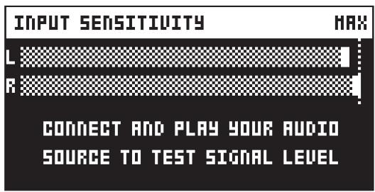
Optimal input level.
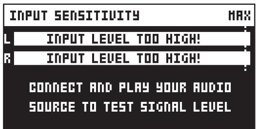
Too high input level.
- Adjust the level at the sound source if needed.
3.3 SETUP EXAMPLES
The Analog Heat +FX is very well suited for use in both an analog setup and in a more digital environment. Here are a couple of examples of how you can use the Analog Heat +FX. For more information about how to set up Analog Heat +FX in different configurations, please see “6.5 AUDIO ROUTING” on page 19.
3.3.1 ANALOG HEAT +FX AS AN EXTERNAL EFFECT
In this example, the Analog Heat +FX is used as an external effect to add color to the Elektron Octatrack before the signal reaches the mixer.

3.3.2 ANALOG HEAT +FX AS A VST/AU/AAX PLUGIN USING OVERBRIDGE
Analog Heat +FX can also be used together with Overbridge to allow you to use the Analog Heat +FX as a plug-in for analog and digital processing sound processing in your DAW.

3.3.3 ANALOG HEAT +FX AS A SOUND CARD
Analog Heat +FX also functions as a 2 in/2 out sound card for your computer and can be used for both recording and monitoring audio. At the same time you can, via Overbridge, use the effect to process another set of audio signals.

4. SIGNAL FLOW
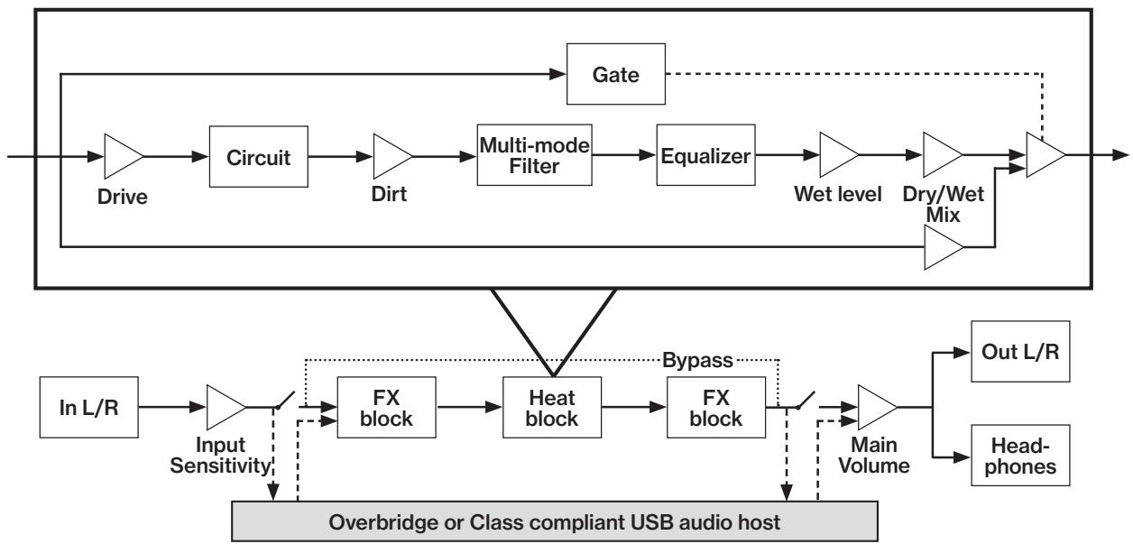
The illustrations below show the signal flows of the Analog Heat +FX and illustrates how the different components interact with each other.
4.1 AUDIO SIGNAL FLOW
This illustration shows the general flow of audio through the Analog Heat +FX. The complete signal chain is in stereo.
4.2 MODULATION SIGNAL FLOW
This illustration shows the flow of how modulation signals are generated and routed through the Analog Heat +FX.

5. INTERACTING WITH THE ANALOG HEAT +FX
5.1 PRESETS
The Analog Heat +FX has 512 preset slots divided into four banks where you can store your presets. Preset slot ... is an INIT preset with default values. Note that, when switching off the power on your Heat, any changes to the currently active preset will be lost unless the preset is first saved. For more information, please see “5.12 SCREEN INFORMATION” on page 15.
5.1.1 LOADING A PRESET
- Press the [FLOW] and [HEAT] keys simultaneously to open the PRESET menu. Turn NAVIGATION to select LOAD PRESET, and then press [YES].
- Press a DATA ENTRY knob to select bank A–D (if you want to load a preset from another bank).
- Turn NAVIGATION to select a preset.
- Press [YES] to load the preset.
5.1.2 SAVING A PRESET
- Press the [FLOW] and [HEAT] keys simultaneously to open the PRESET menu. Turn NAVIGATION to select SAVE PRESET, and then press [YES]. The selected preset starts to blink to illustrate that you are about to overwrite a preset position.
- Press a DATA ENTRY knob to select bank A–D if you want to save the preset to different bank.
- Turn NAVIGATION to select the preset slot to where you want to save your sound and then press [YES].
- (Optional) Turn NAVIGATION to the character you wish to edit. Press and hold [SETTINGS] and then turn NAVIGATION to move the cursor to the desired character and select it by releasing [SETTINGS]. To delete a character, turn NAVIGATION to move the cursor to highlight the character after the one you wish to delete, then press and hold [SETTINGS] and press [NO] twice. To insert a random name, turn CIRCUIT SELECTOR when in the NAMING screen.
- Press [YES] to save the preset.
5.2 ACTIVE
When [ACTIVE] is toggled ON, the Analog Heat +FX affects the incoming signal. The active mode is toggled on and off by pressing [ACTIVE]. A lit [ACTIVE] key indicates that the device is active. You can also use a Footswitch to toggle the active mode. For more information, please see “6.4 CONTROL IN” on page 18. You also have the option to set if you want the Analog Heat +FX to start as active or not when you turn it on, or if you want the [ACTIVE] key to function like a momentary toggle switch. For more information, please see “6.3.4 ACTIVE AT START” on page 18 and “6.3.3 MOMENTARY ACTIVE” on page 18. Press [ACTIVE] again to toggle the device OFF to bypass the effect.
5.3 EFFECT CIRCUITS
You can use the CIRCUIT SELECTOR to in the CHARACTER section choose between 8 different types of effect circuits for a wide variety of drive and distortion sounds.
- CLEAN BOOST
Makes the signal louder. When fully driven, it sounds similar to overdriving old mixers. Use for minimal distortion or when you only want to use the filter and EQ.
- SATURATION
This circuit is reminiscent of classic tape saturation. Woolly and warm.
- ENHANCEMENT
Adding tube-like glow and sheen to a track or loop.
- MID DRIVE
Mid-range focused overdrive with a solid and distinct body.
- ROUGH CRUNCH
Gritty, worn and gnarly character. Full of flavor.
- CLASSIC DIST
Pleasantly distorts upper mid-range frequencies. Ideal for acid bass lines.
- ROUND FUZZ
Adds a lot of harmonics and alters the signal in interesting and often unpredictable ways.
- HIGH GAIN
Probably the most aggressive of all the circuits. Very maxed out!
5.4 FILTER TYPES
Change the type of the filter by pressing one of the two [FILTER TYPE] keys. You can also press the two [FILTER TYPE] keys simultaneously to toggle the filter on/off. It is possible to change the filter type even if the filter is turned off.
There are seven different analog filter types in the Analog Heat +FX to help to shape the sound.
- LOW PASS 2 (two-pole, 12 dB per octave)
- LOW PASS 1 (one-pole, 6 dB per octave)
- BAND PASS
• HIGH PASS 1 (one-pole, 6 dB per octave)
• HIGH PASS 2 (two-pole, 12 dB per octave)
• BAND STOP (NOTCH) - PEAK
5.5 EQUALIZER
LOW and HIGH adjust the amount of low-end and high-end frequency gain or attenuation of the effect circuit. Each effect circuit comes with its tailor-made equalizer characteristics. For more information, please see "4.1 AUDIO SIGNAL FLOW" on page 12.
5.6 DRIVE
DRIVE sets the gain level in the effect circuit. A higher setting increases the effect of the selected circuit type, typically resulting in more distortion. For more information, please see "4.1 AUDIO SIGNAL FLOW" on page 12.
5.7 LEVEL
LEVEL sets the level of the signal coming from the effect. It is applied before the dry/wet mix set by MIX. It is used to match the level of the dry signal for easy mixing of the two. For more information, please see "4.1 AUDIO SIGNAL FLOW" on page 12.
5.8 MIX
MIX sets the mix between the clean (dry) signal and the signal that is affected by the effect (wet). For more information, please see “4.1 AUDIO SIGNAL FLOW” on page 12.
5.9 SETTINGS MENU
Press [SETTINGS] to access the SETTINGS menu.

Scroll through the list of settings by using the NAVIGATION knob. Open a highlighted menu by pressing the NAVIGATION knob or [YES]. To change the settings in the menus, first press, and then turn the NAVIGATION knob. For more information, please see "6. THE SETTINGS MENU" on page 17.
5.10 PARAMETER PAGES
Press a [PARAMETER] page key to access the corresponding parameter pages [FLOW], [HEAT], [FX], and [MOD]. There are usually several parameter pages associated with each key. You access these pages by turning the NAVIGATION knob.. For more information, please see "7. PARAMETER PAGES" on page 25.
5.11 PARAMETER EDITING
The four DATA ENTRY knobs are used to set the parameter values that you see on the screen. (Some parameters also have dedicated knobs on the panel.) The physical location of the knobs on the front panel corresponds to the layout of the parameters on the screen.
- Press down and turn the DATA ENTRY to adjust the parameters in larger increments.
- Press [SETTINGS] + turn DATA ENTRY knob to quantize the parameter value to integers.
- Press [NO] + DATA ENTRY knob to reset the parameter to the default value.
- Press [NO] + [PARAMETER] page key to reset the selected parameter group to default values.
- Use the [NO] key to exit an active menu, back to a higher level menu and to negate.
- Press [PARAMETER] key + [YES] to randomize all parameters on that section's page(es).
5.12 SCREEN INFORMATION

- When on a parameter page, the title bar shows the name of the active parameter page. This text is replaced by parameter names when turning the DATA ENTRY knobs or the dedicated controllers.
- The Audio Input meter displays the level of the incoming audio.
- The Trigger icon shows that the Envelope Follower, an external gate signal or manual triggering has generated a trigger event.
- The graphical information varies depending on the current PARAMETER page.
- The PARAMETER page parameters show what the DATA ENTRY knobs control and their current parameter values.

The Analog Heat +FX features a screen saver that dims the screen after 5 minutes of inactivity and turns off the screen after 60 minutes. Press any key or move any controller to wake up the screen.
5.13 TEMPO
Press the [FX] and [MOD] keys simultaneously to open the TEMPO menu where you can change the BPM setting. Use the two leftmost DATA ENTRY knobs to change tempo. The first sets the coarse BPM and the second sets the decimal. Pressing the knob while turning it changes the tempo two BPM at a time. You can also choose between a global tempo or use a separate tempo for every pattern.
To tap a tempo setting, tap the [YES] key in a steady rhythm. The average tempo of the taps calculates after four consecutive taps. If you continue tapping, the average tempo keeps updating.

5.14 OVERBRIDGE
The Overbridge software suite enables a tight integration between the Analog Heat +FX and a computer DAW software.
When using Overbridge, the user interface for the Analog Heat +FX presents itself as a plug-in window in your DAW. Access, edit and automate parameters for sound shaping on screen. Always find your device preset parameters in the same state as you left them when you return to your DAW project, with the useful total recall functionality.
Read more about Overbridge use and availability on the Elektron website.
5.15 CLASS COMPLIANT DEVICE
The Analog Heat +FX is a class compliant device (also known as plug-and-play). It means it does not require any extra drivers to connect to your Windows or macOS computer, or your iOS device.
The Analog Heat +FX can, therefore, stream audio and MIDI directly over USB to and from supported computers/phones/tablets. It opens up several exciting possibilities of what you can do with your device, for example, record audio from your device directly over USB in your DAW. For more information, please see "6.8.1 USB CONFIG" on page 23 and "6.5.3 USB CC MODE" on page 20
5.16 BACKING UP THE ANALOG HEAT +FX
It is always recommended to make regular backups of your data. Backups are also a convenient way to share your presets with other users. To make backups and transfer files to and from your Elektron device, you should use Transfer, a free application that you can download from the Elektron site https://www.elektron.se/support. The application is available for both Windows and macOS.
5.16.1 BACKING UP PRESETS
You can backup up your presets from your Elektron device to a computer. Here is the general procedure for how to back up your device:
- Connect the Elektron device to the computer via USB.
- Open the Transfer application on your computer, and then select the USB MIDI port(s) for your device on the CONNECTION page, and then click "CONNECT" next to your device under AVAILABLE DEVICES.
- In Transfer, click the EXPLORE tab to open the EXPLORE page.
- On the EXPLORE page top left side of the drop-down menu, make sure "MY COMPUTER" is selected.
- On the top right side, in the drop-down menu, select the type of file you want to transfer.
- In the window on the right, navigate to the files or folders you want to transfer
- Drag and drop the files or folders to your preferred location under "MY COMPUTER."
5.16.2 TRANSFERRING BACKED UP FILES TO YOUR ELEKTRON DEVICE
Use the EXPLORE page in Transfer to transfer previously backed up files to your Elektron device from a computer.
- Connect the Elektron device to the computer via USB.
- Open the Transfer application on your computer and then select the USB MIDI port(s) for your device on the Transfer CONNECTION page. Click "CONNECT" next to your device under AVAILABLE DEVICES.
- In Transfer, click the EXPLORE tab to open the EXPLORE page.
- On the top right side, in the drop-down menu, select the type of file you want to transfer.
- On the top left side in the drop-down menu, make sure "MY COMPUTER" is selected.
- Under "MY COMPUTER," navigate to the files or folders you want to transfer.
- Drag and drop the files or folders to your preferred location on your device.
- Depending on what file type you send, you might encounter pop-up windows asking you to decide what files you want to send and how you want to organize them.
6. THE SETTINGS MENU
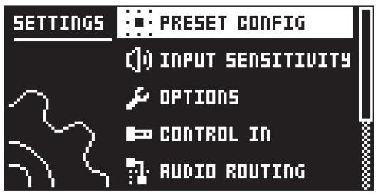
Here follows a description of all the parameters that are in the SETTINGS menu. You access the SETTINGS menu by pressing the [SETTINGS] key. Scroll through the list of settings by using the NAVIGATION knob. Open a highlighted menu by pressing the NAVIGATION knob or [YES]. To change the settings in the menus, first press and then turn the NAVIGATION knob.
6.1 PRESET CONFIG

6.1.1 ANALOG MODE
Disables the digital FX blocks, which makes the Analog Heat +FX audio path analog when this option is enabled.
6.1.2 VOLUME
Preset Volume sets the overall level of the preset. This parameters is also a modulation destination.
6.1.3 OUTPUT GAIN
Sets the gain level of the audio sent to the device's output, headphones and over USB. This gain is added digitally so this parameter is not available in ANALOG mode.

Be aware that high settings of the OUTPUT GAIN parameter may cause unwanted audio clipping/distortion.
6.2 INPUT SENSITIVITY

Sets the audio input level to fit the audio level sent to the effect via the IN L/R inputs. It is important to set this level correctly to get the best sound from your Analog Heat +FX. There are four different settings for the input sensitivity: LOW, MID, HIGH & MAX. Low is the most silent, Max is the loudest. For more information, please see “3.2 SETTING THE INPUT SENSITIVITY LEVEL” on page 10.
- LOW (Maximum input level 10.5 V, peak to peak)
• MID (Maximum input level 5.3 V, peak to peak)
• HIGH (Maximum input level 2.5 V, peak to peak)
• MAX (Maximum input level 1.2 V, peak to peak)
6.3 OPTIONS

6.3.1 PAGE MENU
Will, when selected, display a popup PARAMETER PAGE menu when turning NAVIGATION on a parameter page. This menu can always be viewed by pressing and turning NAVIGATION on a parameter page.
6.3.2 FX PAGE ORDER
Sets the order in which the FX parameter pages are displayed.
- FLOW follows the order of how the FX blocks are arranged on the FLOW page.
• ALPHA sorts the pages in alphabetical order. - FIXED the order is fixed based on the order on the INIT preset.
6.3.3 MOMENTARY ACTIVE
Will (when selected) change the behavior of the [ACTIVE] key and the effect will only be active when the [ACTIVE] key is pressed and held.
6.3.4 ACTIVE AT START
Sets if Analog Heat +FX is in Active Mode or not when it is turned on.
6.3.5 KNOB MODE
Sets how the knobs on the panel affect the parameters. When you load a preset, the knobs positions typically don't match their parameter values.
- JUMP immediately sets the value to the current knob position.
- In CATCH mode, turning the knob do not change the parameter value until the knob position matches the presets stored value.
You can see the current value of the parameter in the screens title bar while you turn the knob.
6.4 CONTROL IN

6.4.1 CONTROL IN A
• CONTROL MODE
Sets the port mode to adjust to different kinds of input signals. There are four modes: CV (Control Voltage), EXPR (Expression Pedal), FOOTSW (Footswitch) and OFF.
• CV ZERO LEVEL (Available when mode is set to CV.)
Sets the Volt level at which CV modulation amount is zero. A control input level equal to this setting corresponds to zero modulation. (-5.50 V–+5.50 V).
• CV MAX LEVEL (Available when mode is set to CV.)
Sets the Volt level at which CV modulation amount is max. A control input level equal to this setting corresponds to full modulation. (-5.50 V–+5.50 V).
- EXPRESSION LEARN (Available when mode is set to EXPR.)
Sets the highest and lowest limit of the control input level. When in this setting, connect the Expression pedal to CONTROL IN A/B. Press YES and then move the expression pedal first to max and then to min position. Press YES to save settings.
• REVERSE DIRECTION (Available when mode is set to EXPR.)
Reverses the direction of how the Expression pedal sends control input signals.
• FOOTSW DEST (Available when mode is set to FOOTSW.)
Sets the destination of the control input from the Footswitch. The options are: TEMPO, ACTIVE, PRESET +, PRESET -, ENV TRIG
• FOOTSWITCH LEARN (Available when mode is set to FOOTSW.)
Sets the high and low limit of the control input level. When in this setting, connect the Footswitch pedal to CONTROL IN A/B. Press YES and then press the Footswitch pedal a couple of times. Press YES to save settings.
• REVERSE DIRECTION (Available when mode is set to FOOTSW.)
Reverses the direction of how the Footswitch pedal sends control input signals.
6.4.2 CONTROL IN B
The available settings are the same as for CONTROL IN A.

If you set CONTROL MODE to FOOTSW you can send a gate signal to the Control In inputs to trigger the envelope generator. For more information, please see "7.4.1 ENV PAGE 1" on page 33.
6.5 AUDIO ROUTING
These settings are stored in the global settings and are not part of the preset.

6.5.1 ANALOG IN/OUT (IN OVERBRIDGE MODE)
Sets if the signal from the analog inputs (INPUT L/R) is routed to the FX blocks or not. It also sets if the signal from the effect is routed to analog outputs (OUTPUT L/R and HEADPHONES) or not. These are the settings if Overbridge mode is chosen in the USB CONFIG menu. For more information, please see "6.8.1 USB CONFIG" on page 23.

Analog Heat +FX supports 4 channels of audio. Audio from Analog Input is routed to the analog in-, and outputs, and can optionally also be routed through the FX blocks. FX Send L/R is always routed to the effect.
- AUTO In AUTO mode, Analog Heat +FX automatically detects if the Overbridge plugin is running or not. With Overbridge running, the Analog In is not routed through the effect to the Analog Out. (Same as OFF setting.) If Overbridge is not running, the signal from Analog In is routed through the FX to the Analog Out. (Same as the IN+OUT setting.)
• IN+OUT Both Analog In and Analog Out are routed to the FX.
• IN Routes the signal from Analog In to the FX.
• OUT Routes the signal from the effect to Analog Out.
• OFF Neither Analog In nor Analog Out are routed to the FX.

You can use the Analog Heat +FX as a regular audio interface and let signals pass in and out unaffected by the effect. At the same time, you can, via Overbridge, also use the effect to process another set of audio signals.
AUTO mode is suitable for most use cases. It lets the Analog Heat +FX function both as a standalone effect and together with Overbridge as a plugin, while still retaining its functionality as a sound card.
6.5.2 ANALOG IN/OUT (IN USB AUDIO/MIDI MODE)
Sets if the signal from the analog inputs (INPUT L/R) is routed to the effect or not. It also sets if the signal from the FX is routed to analog outputs (OUTPUT L/R and HEADPHONES) or not. These are the settings if USB AUDIO+MIDI mode is chosen in the USB CONFIG menu. For more information, please see "6.8.1 USB CONFIG" on page 23.

- AUTO In AUTO mode, Analog Heat +FX automatically detects if a class compliant USB audio host (computer, smartphone, etc.) is connected or not. If no USB audio host is connected, the signal is routed from Analog In through the FX to the Analog Out. (Same as the IN+OUT setting.) With the USB audio host connected, the audio routing in AUTO mode depends on which option is selected by the USB CC MODE parameter:
INSERT sets ANALOG IN/OUT to IN+OUT.
PRE sets ANALOG IN/OUT to OUT.
POST sets ANALOG IN/OUT to IN.
BYPASS sets ANALOG IN/OUT to OFF.
• IN+OUT Both Analog In and Analog Out are routed to the FX.
• IN Routes the signal from Analog In to the FX.
• OUT Routes the signal from the effect to Analog Out.
• OFF Neither Analog In nor Analog Out are routed to the FX.
6.5.3 USB CC MODE
Sets how and where, in the signal chain, the signal between the Analog Heat +FX and the class compliant USB audio host (computer, smartphone etc.) is routed. This parameter is only available if USB AUDIO+MIDI mode is chosen in the USB CONFIG menu. For more information, please see “6.8.1 USB CONFIG” on page 23.

INSERT Routes the audio bi-directionally over USB between the FX (distortion circuit, EQ, and filter) and the USB audio host.
- PRE Routes the audio from Analog In to the USB audio host and then back to the FX.
- POST Routes the audio from the FX to the USB audio host and then to the Analog Out.
- BYPASS Routes the audio from Analog In to the USB audio host and then to Analog Out without being affected by the FX.

Using a USB audio host together with Analog Heat +FX opens up several interesting possibilities of how to use the Analog Heat +FX. Here are some examples and how the ANALOG IN/OUT and USB CC MODE parameters should be set to achieve them:
- Analog Heat +FX as an insert effect for the USB audio host: ANALOG IN/OUT: IN+OUT, USB CC MODE: INSERT
- USB audio host as a pre-Analog Heat +FX insert effect: ANALOG IN/OUT: OUT, USB CC MODE: PRE
- USB audio host as a post-Analog Heat +FX insert effect: ANALOG IN/OUT: IN, USB CC MODE: POST
- Analog Heat +FX as a transparent sound card for the USB audio host: ANALOG IN/OUT: OFF, USB CC MODE: BYPASS
6.5.4 USB TO MAIN
Sets the gain level of the audio sent from the USB audio host to the Analog Heat +FX. This setting only affects the audio sent from the USB audio host to the analog OUTPUT L/R and HEADPHONES outputs. This parameter is only available if USB AUDIO+MIDI or OVERBRIDGE mode is chosen in the USB CONFIG menu, and if it is included in the audio routing chosen in USB CC MODE. For more information, please see "6.8.1 USB CONFIG" on page 23. (0 dB–+18 dB)
6.5.5 FX TO USB
Sets the gain level of the audio sent from the device's FX to the USB audio host. This parameter is only available if USB AUDIO+MIDI mode is chosen in the USB CONFIG menu and if it is included in the audio routing chosen in USB CC MODE. For more information, please see "6.8.1 USB CONFIG" on page 23. (0 dB–+30 dB)
6.6 MIDI CONFIG
These settings are stored in the global settings and are not part of the preset.

6.6.1 SYNC
- CLOCK RECEIVE
Sets whether or not the Analog Heat +FX responds to MIDI clock and transport sent from external devices. (ON, OFF) - CLOCK SEND
Sets whether or not the Analog Heat +FX sends/forwards MIDI Clock and transport. Transport is transmitted when an external clock source (MIDI or Overbridge) is used. (ON, OFF)
• PROG CHG RECEIVE
Sets whether or not the Analog Heat +FX responds to incoming program change messages. This is useful when wanting to select presets from an external source. For more information on how to select the appropriate MIDI channel, please see "6.6.3 CHANNELS" on page 22. (ON, OFF)
• PROG CHG SND
Sets whether or not the Analog Heat +FX sends program change messages when it changes patches. For more information on how to select the appropriate MIDI channel, please see “6.6.3 CHANNELS” on page 22. (ON, OFF)
6.6.2 PORT CONFIG
- TURBO SPEED
This setting allows Turbo mode negotiation between Elektron gear. Connecting the Analog Heat +FX to other Turbo protocol compatible gear, like the Analog Rytm and the Octatrack, makes it
possible to increase the average MIDI bandwidth by up to 10x. This increases the accuracy of MIDI clock signals as well as the timing of CC messages. (ON, OFF)
• OUT PORT FUNC
Sets what type of signal the MIDI OUT port sends.
- MIDI sets the port to send MIDI data.
- DIN24 sets the port to send DIN 24 sync pulses. No MIDI data can be sent on the port when this option is selected.
- DIN48 sets the port to send DIN 48 sync pulses. No MIDI data can be sent on the port when this option is selected.
- THRU PORT FUNC
Sets what type of signal the MIDI THRU port sends. The settings are the same as for OUT PORT FUNC.
- INPUT FROM
Sets the source from which the Analog Heat +FX receives MIDI data.
- MIDI Only receives MIDI data from the MIDI IN port.
- USB Only receives MIDI data from the USB port.
- MIDI+USB Receives MIDI data from both the MIDI IN and USB port.
- NONE Disregards any incoming MIDI data.
- OUTPUT TO
Selects the port to which Analog Heat +FX sends MIDI data (CC or NRPN).
- MIDI Only sends MIDI data to the MIDI OUT port.
- USB Only sends MIDI data to the USB port.
- MIDI+USB Sends MIDI data to both the MIDI OUT and USB port.
- NONE Do not send MIDI data to any port.
• PARAM OUTPUT
Sets what type of MIDI messages the DATA ENTRY knobs sends. For information about which CC/NRPN parameters that are sent, please see “APPENDIX A: MIDI” on page 42.
- CC Sets the knobs to send CC MIDI messages.
- NRPN Sets the knobs to send NRPN MIDI messages.
• ENCODER DEST
Sets whether or not the DATA ENTRY and LEVEL knobs send MIDI data.
- INT MIDI only sends data internally.
- INT + EXT MIDI sends data both internally and externally.
• PARAM INPUT
Makes it possible to control Analog Heat +FX parameters from an external MIDI device sending CC/NRPN data. (ON, OFF)
6.6.3 CHANNELS
- MIDI CH MAIN
Sets the main MIDI channel that Analog Heat +FX uses to send and receive MIDI data.
- MIDI CH FX
Sets the dedicated MIDI channel that is associated with MIDI CC control of the parameters on the parameter pages of the digital FX blocks (all FX blocks except the Heat block). However, MIDI NPRN control uses the channel set by MIDI CH MAIN.
6.7 SYSEX DUMP
In the SYSEX DUMP menu, settings and Presets can be sent and received. Select a menu option using the NAVIGATION knob. Press [YES] to open the highlighted menu selection.

When receiving or sending SysEx data, the MIDI ports or the USB port of the Analog Heat +FX should be connected to the external sending/receiving device.
If the Analog Heat +FX is sending or receiving SysEx data through the MIDI ports, use the Elektron TM-1 USB MIDI interface for up to 10x transfer speeds.

Before initiating a SysEx send or receive, first, make sure the receiving device is listening for data to be sent.
6.7.1 SYSEX SEND
Here settings and Presets can be sent to an external device via the MIDI OUT port or the USB port of the Analog Heat +FX.

The column to the left selects what will be sent. Use the NAVIGATION knob to navigate in the column. The SysEx data send alternatives located in the column to the right will change depending on the selection made in the left column. Press [YES] to access this column. Use the NAVIGATION knob to select what will be sent. Press [YES] to initiate the SysEx send procedure.
SETTINGS will send all the Analog Heat +FX settings to the receiving device.
PRESET will send the selected Preset (or all Presets) to the receiving device.
6.7.2 SYSEX RECEIVE
Here settings and Presets can be received from an external device via the MIDI IN port or the USB port of the Analog Heat +FX.

The column to the left selects what will be received. Use the NAVIGATION knob to navigate in the column. The SysEx data receive alternatives located in the column to the right will change depending on the selection made in the left column. Press [YES] to access this column. Use the NAVIGATION knob to select what will be received. Press [YES] to initiate the SysEx receive procedure. The Analog Heat +FX starts listening to incoming data. Press [NO] to stop listening.
RECEIVE ANY listens to and receives any viable SysEx data (settings, Presets).
PRESET receives and stores a Preset to the selected slot.
6.8 SYSTEM

6.8.1 USB CONFIG
• OVERBRIDGE
To use the Analog Heat +FX as an Overbridge device, select Overbridge mode. (ON, OFF)
- USB MIDI
Select this option If you wish to send MIDI over USB and disable the Overbridge integration functionality. (ON, OFF)
- USB AUDIO/MIDI
Sets the Analog Heat +FX to send and receive audio and MIDI over USB. Select this option if you want to use the Analog Heat +FX together with a class compliant USB audio host. For more information, please see “5.15 CLASS COMPLIANT DEVICE” on page 16. (ON, OFF)
6.8.2 OS UPGRADE
Use this menu option when you want to upgrade the Analog Heat +FX OS. To send the OS syx file, use our free Elektron Transfer software. The OS syx file and Elektron Transfer can be downloaded from the Elektron website.
For the transfer to be possible, the device sending the OS syx file must be connected to the USB port of Analog Heat +FX OS.
Please note that the Analog Heat +FX OS will not appear as an icon on your computer desktop.
- Connect the Elektron device to the computer via USB.
- Open the Transfer application on your computer.
- On the Transfer CONNECTIONS page, set the MIDI IN and MIDI OUT ports to your Elektron device.
- On the Transfer DROP page, drag and drop the OS file. The OS file is then automatically transferred to the Elektron device and the OS update initiates. A progress bar is visible on device screen when receiving the OS.
- On your device. Press [YES] to confirm the OS update.
When the process is successfully completed, the OS is updated and the unit reboots.
6.8.3 CALIBRATION
CALIBRATION starts the calibration routine for the drive circuits and filters. After selecting this option, a popup window appears asking to confirm the calibration. Press [YES] to proceed with the calibration. Please note that the calibration routine takes quite a while to complete.

The device should be turned on for at least 2 hours before you perform a calibration for its circuits to warm up properly. If the unit has not yet warmed up for 2 hours, there is a calibration countdown counter which automatically initiates the calibration once it reaches the timeout.
Also, please note that nothing should be connected to the device during the calibration.
Analog Heat +FX is factory calibrated. It should not be re-calibrated unless specifically stated by Elektron Support or if prompted by the machine.
7. PARAMETER PAGES
Here follows a description of all the parameters that are on the PARAMETER pages. You access the PARAMETER pages by pressing the [PARAMETER] keys.
NAVIGATING THE PARAMETER PAGES
Use the following procedure to navigate and access the HEAT, FX and MOD PARAMETER page groups.
- Press the PARAMETER PAGE key.
- Turn NAVIGATION to select sub-parameter page.
- Use the DATA ENTRY knobs to set the page's parameters.

- When you have selected a sub-parameter page, and there are more than one parameter page in that section (for example FILTER 1/2 and FILTER 2/2), you can press the PARAMETER key to toggle between these two pages.
- You can also randomize the parameter settings on a specific PARAMETER page section (e.g. reverb, delay, LFO). Press [PARAMETER] key + [YES] to randomize all parameters on that section's page(es). Every time you press this key combination, the parameters randomize in a new way.
- Press [PARAMETER] key + [NO] to reset the PARAMETER page to its last saved state.
- Press and hold a [PARAMETER] key to see all the parameter settings on the PARAMETER page.
7.1 FLOW
Press [FLOW] to access this parameter page. This page differs from the other PARAMETER pages since it does not contain any parameters. On this page you can change the order of the FX blocks in the signal flow, bypass/activate each FX block, and set the Dry/Wet mix (or Amount) of each effect block (The Bass Focus block doesn't have any of these parameters). Here you can also see the signal levels for the incoming and outgoing audio signal levels. Exclamation marks above the audio bars means that the signal is so strong it causes clipping. You find the parameter settings for the FX blocks in the FX parameter pages apart from the Heat block's parameters that are in the HEAT parameter pages. For more information, please see "7.3 FX" on page 28

7.1.1 CHANGING THE ORDER OF THE FX BLOCKS
- Turn NAVIGATION to highlight the FX block you want to move
- Press NAVIGATION to select and lift the highlighted FX block.
- Turn NAVIGATION to move the FX block to the desired position in the path.
- Press NAVIGATION to place the FX block in its new position.
7.1.2 SETTING THE DRY/WET MIX OF THE FX BLOCKS
- Press and hold [FLOW], and then turn NAVIGATION to select FX block row.
- Use the DATA ENTRY knobs to set the Dry/Wet mix of the FX blocks on the selected row.

7.1.3 BYPASSING/ACTIVATING AN FX BLOCK
You can set if an FX block should be bypassed or active.
- Turn NAVIGATION to select the FX block you want to bypass/activate
- Press the [YES] and [NO] keys simultaneously to bypass/activate the selected FX block. A bypassed FX block is shown on the screen with a dotted rectangle around it.

- An FX block can also be bypassed/activated by pressing [YES] and [NO] simultaneously whilst on a parameter page of the respective block.
- When bypassing the HEAT block, all LEDs in the CHARACTER and FILTER section of the panel will be turned off.
- Press [YES] to open the selected FX block's first PARAMETER page.

If ANALOG MODE is set to on, all FX blocks apart from the HEAT block are bypassed. For more information, please see "6.1.1 ANALOG MODE" on page 17.
7.2 HEAT
Press [HEAT] to access these parameter pages.
The Heat FX block consists of analog circuits that shapes the audio signal with drive, effect circuit (accessed from the device's front panel), filter, EQ, and gate.
7.2.1 AMP

DRIVE Sets the gain level of the audio into the distortion circuit. A higher setting results in more distortion. Even at zero level some of the circuits have a clear effect on the sound.
LEVEL Sets the level of the signal that is affected by the effect. Use LEVEL to balance the Wet part of the signal so that it has a similar level as the Dry part. This makes it easier to use the MIX parameter to do parallel distortion. For more information, please see “4.1 AUDIO SIGNAL FLOW” on page 12.
MIX Sets the mix between the clean signal and the signal that is affected by the effect.
7.2.2 FILTER 1/2

FREQ Sets the cutoff frequency of the filter.
RESO Sets the amount of resonance at the cutoff point of the filter.
ENV Sets the amount of how much the envelope and envelope follower affects the filter frequency. A negative value gives an inverted modulation.
LFO Sets the amount of how much the LFO affects the filter frequency. A negative value gives an inverted modulation.
7.2.3 FILTER 2/2

FRQPAN Adjust the cutoff frequency of the filter and pans its behavior between the Left and Right channel. At a value of 0 there is no frequency panning effect. Lower values increase the cutoff frequency in the Left channel and decrease it in the Right channel. Higher values increase the cutoff frequency in the Right channel and decrease it in the Left channel.
DIRT This parameter sets the amount of input level to the filter. It can be used to slightly overdrive the signal going into the filter, producing filter distortion.
EQ LO Controls the amount of low-end in the equalizer. Depending on selected circuit-type, this affects the low-end in slightly different ways, always tailor-made to suit the characteristics of the selected circuit.
EQ HI Controls the amount of high-end in the equalizer. Depending on selected circuit-type, this affects the high-end in slightly different ways, always tailor-made to suit the characteristics of the selected circuit.
7.2.4 GATE
The gate is used to control the volume of the audio signal. It attenuates signals that are below the set threshold level. The gate will attenuate the signal by a fixed amount, known as the range. Simply explained, the gate allows a signal to pass through only when it is above a set threshold: the gate is open. If the signal falls below the threshold no signal is allowed to pass (or the signal is attenuated): the gate is closed.

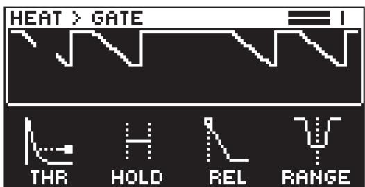
THRESHOLD Sets the audio input level at which the gate will open and let through a signal.
HOLD Sets the amount of time from which the signal goes under the threshold level to when the release phase begins.
RELEASE Sets the time for the gate to go from open to fully closed.
RANGE Sets the amount of signal volume when the gate is closed. The most common setting is to have complete attenuation, that is, no signal will pass when the gate is closed.
7.3 FX
Press [FX] to access these parameter pages.
7.3.1 BITS

SRR (Sample Rate Reduction) sets the amount of sample rate reduction.
BR (Bit Reduction) sets the bit rate. The parameter range is from 16 bits to 2 bits.
FLTR Filter for the SRR and BR effects. The parameter ranges from a low-pass filter to a high-pass filter. Negative parameter values set a low-pass filter. Positive parameter values set a high-pass filter.
MIX Sets the mix between the clean signal and the signal that is affected by the effect.
7.3.2 WARBLE PAGE 1

DEPTH Sets the depth of the warble effect
SPEED Sets the speed of the warble effect: A setting of 0 makes the speed random.
BASE Sets the base frequency of the filter.
WIDTH Sets the frequency width above the base frequency.
7.3.3 WARBLE PAGE 2

N LEV Noise Level sets the amount of noise that is added to the effect.
HPF High-pass filter sets the frequency for the highpass filtering of the noise.
STEREO Stereo Width sets the amount of the warble effect in the stereo field.
MIX Sets the mix between the clean signal and the signal affected by the effect.
7.3.4 COMPRESSOR PAGE 1
The Compressor compresses the dynamic range of the signal by reducing the volume of loud sounds relative to the quiet sounds. The screen shows the input/outputs signals and the gain reduction.

THR Threshold sets the threshold of the compressor. A lower threshold means a larger portion of the signal is subject to compression.
ATK Attack sets the time of the compressor attack phase, i.e. how quickly the compressor responds to loud peaks.
REL Release sets the time of the compressor release phase, i.e. how long it takes for the compression to recover in quieter moments.
MUP Makeup Gain sets the makeup gain of the compressor output, to compensate for the reduced signal levels caused by compression. The Makeup Gain parameter value is displayed in dB.
7.3.5 COMPRESSOR PAGE 2

RATIO Compression Ratio. There are eight different compression ratios, 1.50, 2.00, 3.00, 4.00, 6.00, 8.00, 16.00 and 20.00. Higher ratios result in greater compression of the signal.
SC FLTR Sidechain Filter filters the audio signal before the compressor analyzes it. The parameter ranges from a low-pass filter to a high-pass filter. Negative parameter values sets a low-pass filter. Positive parameter values sets a high-pass filter.
When set as a low-pass filter, the compressor reacts mostly to bass frequencies. Use this setting for a characteristic pumping compressor sound. When set as a high-pass filter, the compressor reacts less to bass frequencies. Use this setting to avoid pumping.
MIX Sets the mix between the clean signal and the signal that is affected by the effect.
The Analog Heat + FX compressor

7.3.6 BASS FOCUS
This FX block can be used to detect and correct any stereo phase problems in the low-end register of the signal. It uses a crossover filter to divide the signal into a low band and a high band, allowing you to make the low band part of the signal mono. You can also attenuate the two bands separately. The -1 to 1 meter displays the amount of phasing in the low band. A positive value means that the signal does not
have any phasing issues. A value of 1 tells that the signal is fully in mono. A negative value is a sign that the low band audio has problems with phasing.

BASS Sets if the low band part of the signal should be in stereo or mono.
XFREQ Crossover frequency sets the frequency of the crossover filter.
LP LEV Sets the attenuation of the low band part of the signal.
HP LEV Sets the attenuation of the high band part of the signal.
7.3.7 CHORUS
The chorus can be used to widen sounds, enhance the stereo image or add subtle movement to sounds.

DEPTH Depth sets the depth of the LFO modulation of the chorus.
SPEED Speed sets the speed of the LFO modulation of the chorus.
WIDTH Width sets the stereo width of the chorus.
MIX Sets the mix between the clean signal and the signal that is affected by the effect.
7.3.8 DELAY PAGE 1
The delay send effect takes the input signal, delays it in time and then adds it to the original signal.

TIME Delay Time sets the delay time. The delay time settings are relative to the current BPM and is measured in 128th notes.
| TIME setting | Divide ratio |
| 1 | 1/128 |
| 2 | 1/64 |
| 2.67 | 1/48 (1/32T) |
| 3 | 1/64. |
| 4 | 1/32 |
| 5.33 | 1/24 (1/16T) |
| 6 | 1/32. |
| 8 | 1/16 |
| 10.67 | 1/12 (1/8T) |
| 12 | 1/16. |
| 16 | 1/8 |
| 21.33 | 1/6 (1/4T) |
| 24 | 1/8. |
| 32 | 1/4 |
| 42.67 | 1/3 (1/2T) |
| 48 | 1/4. |
| 64 | 1/2 |
| 96 | 1/2. |
| 128 | 1 |
PING Ping-pong sets the delay signal to alternate across the stereo field. There are two settings:
OFF lets you manually set the position of the delay signal in the stereo field. Use the WID parameter to change the stereo field position.
ON makes the delay signal alternate between left and right pan positions. The WID parameter controls the amount of panning.
WIDTH Stereo Width sets the delay signal pan width across the stereo field. The knob is bipolar.
FDBK Feedback Gain sets the amount of delay output signal to feed back into the input of the delay. With higher parameter settings, infinite and swelling delays are possible. Please be aware that high feedback can lead to a very loud signal.
7.3.9 DELAY PAGE 2

HPF Sets the cutoff frequency of the delay highpass filter.
LPF Sets the cutoff frequency of the delay lowpass filter.
MODE Sets what the AMOUNT parameter controls.
SEND In this mode, AMOUNT controls the level of the dry signal sent to the delay.

RETURN In this mode, AMOUNT controls the level of the wet signal returning from the delay.

MIX In this mode, AMOUNT controls the mix of the dry and wet signals.

AMOUNT Sets the amount of signal sent to or from the delay depending on the selected MODE.
7.3.10 REVERB PAGE 1
The reverb send effect controls the persistence, and ambient characteristics, of the sound reverberations. It can simulate many different sonic locations, from huge spaces to small rooms.

PRE Pre-delay sets the pre-delay time of the Reverb.
DEC Decay Time sets the length of the decay phase of the reverberated signal, essentially setting the size of the acoustic space.
FREQ FB Shelving Freq sets the shelving filter frequency. Together with the GAIN parameter, it can be used to dampen the reverberated signal above a chosen frequency, making the reverberation sound more prominent or more muffled.
GAIN FB Shelving Gain affects the damping of the reverberated signal above the shelving frequency set by the FREQ parameter. At max value the treble is included in the reverberations; lowering the value gradually dampens it.
7.3.11 REVERB PAGE 2

HPF Sets the cutoff frequency of the reverb highpass filter.
LPF Sets the cutoff frequency of the reverb lowpass filter.
MODE Sets what the AMOUNT parameter controls.
SEND In this mode, AMOUNT controls the level of the dry signal sent to the reverb.

RETURN In this mode, AMOUNT controls the level of the wet signal returning from the reverb.

MIX In this mode, AMOUNT controls the mix of the dry and wet signals.

AMOUNT Sets the amount of signal sent to or from the reverb depending on the selected MODE.
7.4 MOD
Press [MOD] to access these parameter pages.
7.4.1 ENV PAGE 1

Analog Heat +FX contains an envelope follower function. The envelope follower is used to detect the amplitude variations of the incoming audio signal to produce a control signal (envelope) that resembles those variations. The control voltage rises and falls with the overall volume of the input signal. This control signal is routed to modulate the filter and also to two other modulation destinations of your choice. For more information, please see “7.4.9 MATRIX” on page 37. Tightly coupled with the Envelope Follower is also an Envelope Generator. If you do not want to use the follower output directly, you can choose to use the follower only to trigger the Envelope Generator, if you want to use predefined Attack/Decay (or Attack/Release) times rather than follow the audio with the rise/fall slopes. For more information, please see “4.2 MODULATION SIGNAL FLOW” on page 12.
MODE Sets the mode of the envelope follower. Turn the knob to access the next mode. The higher the value under the selected mode, the more gain is added to the signal, which is useful for weak input signals.
• AR (Attack-Release)
Creates an envelope control signal where the Attack phase begins when the incoming sound exceeds the threshold. The envelope then holds until the incoming sound falls under the threshold and the release phase starts

• AD (Attack-Decay)
Creates an envelope control signal where the Attack phase begins when the incoming sound exceeds the threshold and is then followed directly by the decay phase.

- FLW (Follow)
The envelope follows the amplitude of the input signal when it is above the threshold level.

ATK In Follow (FLW) mode, this is the rise time of the envelope follower, i.e. how quickly the follower rises when the amplitude of the audio increases. In generator mode (AD or AR), this is the attack time of the generated envelope. The rise time of the underlying envelope follower is set to fastest possible rise time in these configurations.
REL In Follow (FLW) mode, this is the fall time of the envelope follower, i.e. how quickly the follower falls when the amplitude of the audio falls. In generator mode (AD or AR), this is the decay- or release time of the generated envelope. The fall time of the underlying envelope follower is set to a good, predefined fall time in these configurations.
TRIG Sets the threshold level for when the envelope follower triggers the envelope generator and LFO.

Press [YES] + [MOD] to trigger the envelope generator manually. You can also send a gate signal to the Analog Heat +FX Control In inputs to trigger the envelope generator. For more information, please see “6.4 CONTROL IN” on page 18.
7.4.2 ENV PAGE 2

The envelope has three modulation destinations.
- The first destination is set using the parameter DEST1. DEPTH1 controls the amount of envelope modulation sent to the chosen destination. The first destination can also be set in the MATRIX parameter page. Select ENV 1ST as a source and then select modulation destination and modulation depth. For more information, please see "7.4.9 MATRIX" on page 37.
- The second destination is set in the MATRIX parameter page. Select ENV 2ND as a source and then select modulation destination and modulation depth.
- The third modulation destination is permanently set to the FREQ parameter of the analog filter in the Heat FX block. The parameter ENV on the FILTER/EQ PAGE 1 parameter page controls the amount of envelope modulation added to the filter cutoff.
The envelope follower uses a filter to define the frequency span of the input signal that the envelope follower reacts to. This span is defined by the BASE and WIDTH parameters.
Examples of how the BASE and WIDTH parameters affect the filter of the envelope follower:

FREQUENCY

FREQUENCY

FREQUENCY

With BASE set to 0, the envelope follower filter functions as a low pass filter with WIDTH adjusting the frequency range.
With WIDTH set to 127, the envelope follower filter functions as a high pass filter with BASE adjusting the frequency range.
If you want the envelope follower to trigger specifically on different types of drums in a loop (for example the hi-hats), this filter is very usable to isolate these elements.
BASE Sets the base frequency of the filter detection.
WIDTH Sets the frequency width above the base frequency.
DEST1 Sets the modulation destination of the envelope follower. Turn the DATA ENTRY knob to highlight the destination and then press the DATA ENTRY knob or [YES] or to select the destination. For more information, please see "APPENDIX B: MODULATION SOURCES AND DESTINATIONS" on page 45.
DEPTH1 Sets the amount of how much the envelope follower affects the modulation destination. A negative value gives an inverted modulation.
7.4.3 LFO1 PAGE 1

SPEED Sets the rate of the LFO in relation to the internal or external tempo. It is synced to BPM if one of the “BPM x” settings are selected in the MULT parameter. To sync the LFO to straight beats, try settings of 16 or 32. The value of this parameter is bi-polar. (The LFO shape can be played backward by using negative values.)
MULT Multiplies the SPEED parameter by the set factor. (x) multiplies the current BPM. 1-2K multiplies the LFO speed regardless of the current internal or external tempo.
WAVE Sets the LFO waveform. (TRI, SINE, SQR, SAW, EXP, RAMP, RND)
START Sets where in the LFO waveform cycle it starts when triggered. For example, if you set WAVE to SAW and START to 64 it starts at the middle of the wave cycle. If WAV is set to RND then the START parameter will instead add slew to the transitions in the waveform.

Start set to 64
7.4.4 LFO1 PAGE 2
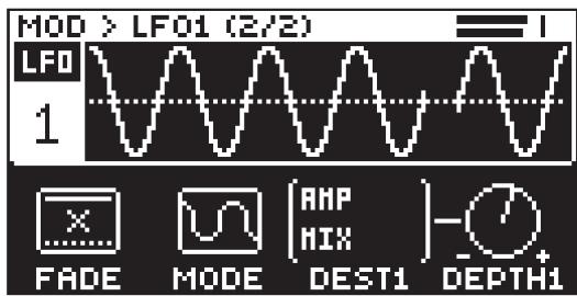
The LFO has three modulation destinations.
- The first is set using the parameter DEST1. The amount of LFO modulation added to the selected destination is controlled by the parameter DEPTH1. The first modulation destination can also be set in the MATRIX parameter page. Select LFO 1ST as a source and then select modulation destination and modulation depth. For more information, please see "7.4.9 MATRIX" on page 37.
- The second destination is set in the MATRIX parameter page (see above). Select LFO 2ND as a source and then select modulation destination and modulation depth.
- The third modulation destination is permanently set to the filter cutoff. The amount of LFO modulation added to the filter cutoff is controlled by the parameter LFO on the FILTER/EQ PAGE 1 parameter page.
FADE offers the possibility to fade in/out the LFO modulation. Positive values give a fade-out, negative values give a fade-in. A middle position (0) results in no fade in/out. The fade curve is restarted each time the LFO triggers.
MODE Selects between five different modes of LFO behavior.
- FREE is the default free-running mode. The LFO run continuously, never restarting or stopping.
- TRIG The LFO run continuously, but restarts on the event of an envelope trig. Please note that LFO3 does not restart by an envelope trig.
- HOLD The LFO run continuously, but on the event of an envelope trig, the output LFO level is latched and held still until the next envelope trig
- ONE The LFO starts when a note is triggered, then runs to the end of the waveform and then stops. This makes the LFO function similar to an envelope.
- HALF The LFO starts when a note is triggered, then runs halfway through the waveform and then stops.
DEST1 Sets the first modulation destination of the LFO. Turn the DATA ENTRY knob to highlight the destination and then press the DATA ENTRY knob or [YES] or to select the destination. For more information, please see "APPENDIX B: MODULATION SOURCES AND DESTINATIONS" on page 45.
DEPTH1 Sets the amount of how much the LFO affects the modulation destination. A negative value gives an inverted modulation.
7.4.5 LFO2 PAGE 1
This page contains the same parameter as LFO1 PAGE 1 but instead controls LFO2.
7.4.6 LFO2 PAGE 2
This page contains the same parameter as LFO1 PAGE 2 but instead controls LFO2.
7.4.7 LFO3 PAGE 1
This page contains the same parameter as LFO1 PAGE 1 but instead controls LFO3.
7.4.8 LFO3 PAGE 2
This page contains the same parameter as LFO1 PAGE 2 but instead controls LFO3.
7.4.9 MATRIX

On the Modulation matrix page you can connect a number of modulation sources with their destinations and set the modulation depth. For more information, please see “APPENDIX B: MODULATION SOURCES AND DESTINATIONS” on page 45.
- Turn the leftmost DATA ENTRY knob to scroll through the source list and select the source.
- Turn the third DATA ENTRY knob to scroll through the destination list and select the destination.
- Lastly, use the rightmost DATA ENTRY knob to set the modulation depth.

- LFO3 can modulate the envelope parameters. LFO3 can not be modulated by the envelope.
- LFO3 is not triggered by the envelope. However, you can trigger the LFO either from an external source or manually by pressing [LFO] + [YES]. So, without any external/manual trigs, the LFO3's TRIG mode works the same as the FREE mode. In HOLD, ONE, and HALF modes, the LFO will not affect the modulation destination without being triggered.
8. TIPS & TRICKS
Here you can find a couple of different examples of some of the things you can do with the Analog Heat +FX.
8.1 ADDING SATURATION TO THE HIGH REGISTER
You can use the Analog Heat +FX to add saturation to the high-frequency register of a full range mix. This is useful when you want to introduce some subtle harmonics to the mix, without distorting the overall sound.
- Select the SATURATION circuit and the HIGH PASS 2 filter.
- Connect your sound source to the Analog Heat +FX and make sure that the volume of the sound source is as strong as possible.
- Make sure the input level is correctly set. For more information, please see "3.2 SETTING THE INPUT SENSITIVITY LEVEL" on page 10.
- Start by setting DRIVE to 0, LEVEL to 127, and MIX to 0. Set the filter RESONANCE to 0 and FREQUENCY to 100.
- Increase DRIVE until you start to hear a little saturation in the higher registers, but not so much that the saturation gets too dominant. The processed signal is lower than the bypassed signal, so you should adjust the preset volume to match the active and bypassed state to be able to A/B test correctly.
- Tweak MIX and DRIVE until you find a nice balance and the sound you want. If you want to use the EQ, remember that only HIGH EQ affects the sound, since the low frequencies are filtered out.
8.2 ANALOG PSEUDO-COMPRESSION
You can use the Analog Heat +FX to emulate a compressor and/or expander by using the Envelope Generator. This is useful if you want to add some extra pump to drums, or to liven up a flat sound. In this example, you should use a highly dynamic sound source, with sharp transients, such as drums.
- Select the CLEAN BOOST circuit and disable the filter by pressing both [FILTER TYPE] keys at the same time. All filter type LEDs should be turned off.
- Connect your sound source to the Analog Heat +FX and make sure that the volume of the sound source is as strong as possible.
- Make sure the input level is correctly set. For more information, please see "3.2 SETTING THE INPUT SENSITIVITY LEVEL" on page 10.
- Start by setting DRIVE to 0, LEVEL to 127, and MIX to 127.
- Press the [HEAT] key, navigate to the AMP page, and set VOL to 127.
- Press the [MOD] key, navigate to ENVELOPE page 1, and set MODE to AD. Adjust the MODE (AD) parameter until you clearly see the incoming signal in the TRIG meter. You should see the peaks and dips of the incoming signal, retaining as much as possible of dynamics of the signal.
- Lower the TRIG value until you see the trigger icon blink in the upper right corner of the screen. Make sure it triggers mainly from the strongest peaks of the incoming sound.
- Set ATK to 48, and REL to 72.

- Press the [MOD] key, navigate to ENVELOPE page 2 and change DEST1 to PST VOLUME and DEPTH1 to -72.
You should now hear a very dynamic ducking effect with pretty sharp transients. You can change VOL, ATK, REL, and DEPTH1 to achieve different compression effects.
If you change VOL to 80 and apply positive modulation (DEPTH1), you expand the signal instead of compress it.
Bonus: Adding LFO
- Press the [MOD] key, and then navigate to LFO page 1.
- Set WAVE to SQR, SPEED to 1, and MULT to x1.
- Press the [MOD] key, and then navigate to LFO page 2.
- Set DEST1 to PRESET VOL, MODE to TRI, and FADE to 40.
- Apply positive modulation from DEPTH1 for even louder transients.
Note that DEPTH1 on ENVELOPE PAGE 2 need to be lowered to make room for the LFO modulation.
8.3 STEREO PHASER EFFECT
The Analog Heat +FX can also achieve an effect similar to that of a classic stereo phaser pedal by using the filter frequency panning function.
- Select any circuit and set the [FILTER TYPE] to BAND STOP.
- Connect your sound source to the Analog Heat +FX and make sure that the volume of the sound source is as strong as possible.
- Make sure the input level is correctly set. For more information, please see "3.2 SETTING THE INPUT SENSITIVITY LEVEL" on page 10.
- Start by setting LEVEL to 127, and MIX to 63. Set FREQUENCY to 64, and RESONANCE to 0.
- Press the [LFO] key, and then navigate to LFO page 2, and change DEST1 to FILTER PAN and set DEPTH1 to around +64.
- Press the [LFO] key, and then navigate to LFO page 1 and set SPEED to your liking.
You should now hear a phasing effect applied to your sound. Try playing around with the LFO waveforms, speed, and depth, as well as the filter frequency. The different Filter Types have a different impact on the sound when you use the filter frequency panning.
9. STARTUP MENU
To access this menu, hold down the [ACTIVE] key while powering up the Analog Heat +FX. From here you can perform a variety of tasks.
9.1 TEST MODE
To enter this mode, press the [FLOW] key.

Remember to turn down the volume on all speakers and headphones before activating Test mode. For testing purposes, a short sound is heard through all outputs of the Analog Heat +FX.
If you have any trouble with your Analog Heat +FX and suspect it may be due to a hardware problem, perform this self-test. Use the NAVIGATION knob to scroll through the test log. A fully functional device should not report any errors. If it does report an error, please contact Elektron support or the retailer that you bought your Analog Heat +FX from.
9.2 EMPTY RESET
To perform an empty reset, press the [HEAT] key. This will reset the device and erase all presets.
9.3 FACTORY RESET
To perform a factory reset, press the [FX] key. This will reset the device and overwrite preset 001-016 with factory presets. The remaining preset slots will be empty.
9.4 OS UPGRADE
Initiate the OS upgrade by pressing the [MOD] key. Use this menu option if you for some reason cant upgrade the Analog Heat +FX OS using the standard procedure in the SYSTEM menu. To send the OS file, use our free Elektron Transfer software. The Elektron Transfer can be downloaded from the Elektron website.
- Download the Analog Heat +FX OS file from the Elektron website.
- Connect the Analog Heat +FX's MIDI IN port to the MIDI OUT port of the computer's MIDI interface.
- Hold down the [ACTIVE] key while powering on Analog Heat +FX. This takes you to the STARTUP menu.
- Press the [MOD] key to enter OS UPGRADE mode.
- Open the Transfer application on your computer. On the Transfer CONNECTION page, click "go to the SYSEX TRANSFER page".
- On the SYSEX TRANSFER page, click "OS Upgrade via device startup menu", and then follow the on-screen instructions.
When the update is done, the Analog Heat +FX will reboot.

USB MIDI transfer is not possible when upgrading the OS from the STARTUP menu.
10. TECHNICAL INFORMATION
ELECTRICAL SPECIFICATIONS
Impedance balanced audio outputs
Main outputs level: +19 dBu
Output impedance: 440 Ω unbalanced
Headphones output
Headphones out level: +19 dBu
Output impedance: 36 Ω
Balanced audio inputs
Input level: +19 dBu peak
Audio input impedance: 39 kΩ
Control inputs
Input level on tip: -5 V–+5 V. Supplies +5 V on ring
Accepts CV, Expression pedals, Footswitches
Unit power consumption: 12 W typical
Recommended power supply: PSU-3/b/c, 12 V DC, 2A
HARDWARE
128×64 pixel OLED screen
MIDI In/Out/Thru with DIN Sync out
2 x 1/4" impedance balanced audio out jacks
2 x 1/4" balanced audio in jacks
1 x 1/4" stereo headphone jack
2 x 1/4" control input jacks
48 kHz, 24-bit D/A and A/D converters
Electrically isolated Hi-speed USB 2.0 port
Power inlet: Center positive 5.5 x 2.5 mm barrel jack,
12 V DC, 2A
PHYSICAL SPECIFICATIONS
Sturdy steel casing
Dimensions: W 215 x D 184 x H 63 mm (8.5" x 7.2" x
2.5") (including power switch, jacks, knobs and feet)
Weight: approximately 1.5 kg (3.3 lbs)
100 x 100 mm VESA mounting holes. Use M4
screws with a max length of 7.4 mm.
Maximum recommended ambient operating
temperature: +35°C (+96°F)
11. CREDITS AND CONTACT INFORMATION
CREDITS
ELEKTRON CREW
Lennart Ahlstedt
Oscar Albinsson
Vladyslav Aleksashyn
Johannes Algelind
Fredrik Alm
Magnus Almberg
Christian Alsing
Hans Alvarsson
Deva Andar
Nikolaj Andersson
Madeleine Antonsson
Andreas Brykt
Shelby Cinca
Johan Damerau
Oscar Dragén
Erika Earl
Magnus Forsell
Jennifer Giöbel
Andreas Henriksson
Mario Adriane Hernandez
Tomas Hjalmarsson
Thomas Jansson
Patrik Johansson
Christian Karlsson
George Kaplan
Åsa Larsson
Erik Liakhovets
Christer Lindström
Joel Lundberg
Sandra Magnusson
Johannes Mai
Enrique Martinez
Martin Mellström
Taylor Morken
Jimmy Myhrman
Viktor Nilsson
Jean Michel Pepin
Mattias Rickardsson
Patrik Rinvall
Alex Schetter
Martin Sigby
David Smallbone Tizard
Che Thomas
Gösta Wellmer
Jake Widgeon
Vladislav Zhukov
Erik Ångman
CONTACT INFORMATION
ELEKTRON WEBSITE
http://www.elektron.se
OFFICE ADDRESS
Elektron Music Machines MAV AB
Banehagsliden 5
SE-414 51 Gothenburg
Sweden
APPENDIX A: MIDI
This appendix lists the CC and NRPN numbers for the Analog Heat +FX.
The following parameters are accessed using the midi channel set by MIDI CH MAIN. For more information, please see “6.6.3 CHANNELS” on page 22.
| Parameter | CC MSB | CC LSB | NRPN MSB | NRPN LSB | Specific values info |
| AMP Circuit Select | 108 | 1 | 108 | 0=CB, 1=SA, 2=EN, 3=MD, 4=RC, 5=CD, 6=RF, 7=HG | |
| AMP Drive | 109 | 37 | 1 | 109 | |
| AMP Level | 110 | 39 | 1 | 110 | |
| AMP Mix | 111 | 40 | 1 | 111 | |
| PST Volume | 112 | 1 | 112 | ||
| EQ Low | 28 | 41 | 1 | 28 | |
| EQ High | 29 | 42 | 1 | 29 | |
| VCF Mode | 30 | 1 | 30 | 1=LP2, 3=LP1, 5=BP, 7=HP1, 9=HP2, 11=BS, 13=PK | |
| VCF Frequency | 22 | 43 | 1 | 22 | |
| VCF Frequency Pan | 26 | 47 | 1 | 26 | |
| VCF Resonance | 23 | 44 | 1 | 23 | |
| VCF Dirt | 27 | 1 | 27 | ||
| ENV to Filter | 24 | 45 | 1 | 24 | |
| LFO to Filter | 25 | 46 | 1 | 25 | |
| ENV Threshold | 12 | 32 | 1 | 12 | |
| ENV Attack | 13 | 1 | 13 | ||
| ENV Release | 14 | 1 | 14 | ||
| ENV Base | 15 | 1 | 15 | ||
| ENV Width | 16 | 1 | 16 | ||
| ENV Mode | 17 | 1 | 17 | ||
| ENV Destination | 18 | 1 | 18 | ||
| ENV Depth | 19 | 33 | 1 | 19 | |
| ENV Destination 2 | 20 | 1 | 20 | ||
| ENV Depth 2 | 21 | 1 | 21 | ||
| LFO1 Waveform | 66 | 1 | 66 | 0=TRI, 1=SIN 2=SQR, 3=SAW, 4=EXP, 5=RAMP, 6=RND | |
| LFO1 Speed | 67 | 1 | 67 | ||
| LFO1 Multiplier | 68 | 1 | 68 | ||
| LFO1 Fade | 69 | 1 | 60 | ||
| LFO1 Mode | 70 | 1 | 70 | 0=FREE, 1=TRIG, 2=HOLD, 3=ONE, 4=HALF | |
| LFO1 Start Phase | 71 | 1 | 71 | ||
| LFO1 Destination | 72 | 1 | 72 | ||
| LFO1 Depth | 73 | 34 | 1 | 73 | |
| LFO1 Destination 2 | 74 | 1 | 74 | ||
| LFO1 Depth 2 | 75 | 1 | 75 | ||
| LFO2 Waveform | 76 | 1 | 76 | 0=TRI, 1=SIN 2=SQR, 3=SAW, 4=EXP, 5=RAMP, 6=RND | |
| LFO2 Speed | 77 | 1 | 77 | ||
| LFO2 Multiplier | 78 | 1 | 78 | ||
| LFO2 Fade | 79 | 1 | 79 | ||
| LFO2 Mode | 80 | 1 | 80 | 0=FREE, 1=TRIG, 2=HOLD, 3=ONE, 4=HALF | |
| LFO2 Start Phase | 81 | 1 | 81 | ||
| LFO2 Destination | 82 | 1 | 82 | ||
| LFO2 Depth | 83 | 35 | 1 | 83 | |
| LFO2 Destination 2 | 84 | 1 | 84 | ||
| LFO2 Depth 2 | 85 | 1 | 85 | ||
| LFO3 Waveform | 86 | 1 | 86 | 0=TRI, 1=SIN 2=SQR, 3=SAW, 4=EXP, 5=RAMP, 6=RND | |
| LFO3 Speed | 87 | 1 | 87 | ||
| LFO3 Multiplier | 88 | 1 | 88 | ||
| LFO3 Fade | 89 | 1 | 89 | ||
| LFO3 Mode | 90 | 1 | 90 | 0=FREE, 1=TRIG, 2=HOLD, 3=ONE, 4=HALF | |
| LFO3 Start Phase | 91 | 1 | 91 | ||
| LFO3 Destination | 92 | 1 | 92 | ||
| LFO3 Depth | 93 | 36 | 1 | 93 | |
| LFO3 Destination 2 | 94 | 1 | 94 | ||
| LFO3 Depth 2 | 95 | 1 | 95 | ||
| CV A Destination | 100 | 1 | 102 | ||
| CV A Depth | 101 | 1 | 103 | ||
| Expr. A Destination | 102 | 1 | 104 | ||
| Expr. A Depth | 103 | 1 | 105 | ||
| CV B Destination | 104 | 1 | 106 | ||
| CV B Depth | 105 | 1 | 107 | ||
| Expr. B Destination | 106 | 1 | 108 | ||
| Expr. B Depth | 107 | 1 | 109 | ||
| GATE Threshold | 113 | 1 | 113 | ||
| GATE Hold | 114 | 1 | 114 | ||
| GATE Release | 115 | 1 | 115 | ||
| GATE Range | 116 | 1 | 116 |
The following parameters CC values should be sent to the Analog Heat +FX on the midi channel set by MIDI CH FX. The parameters NRPN values should be sent on the midi channel set by MIDI CH MAIN. For more information, please see “6.6.3 CHANNELS” on page 22.
| Parameter | CC MSB | CC LSB | NRPN MSB | NRPN LSB | Specific values info |
| BITS SRR | 88 | 2 | 88 | ||
| BITS BR | 89 | 2 | 89 | ||
| BITS Filter | 90 | 2 | 90 | ||
| BITS Mix | 91 | 2 | 91 | ||
| CHORUS Depth | 102 | 36 | 2 | 102 | |
| CHORUS Speed | 103 | 37 | 2 | 103 | |
| CHORUS Width | 105 | 2 | 105 | ||
| CHORUS Mix | 106 | 2 | 106 | ||
| DELAY Time | 107 | 39 | 2 | 107 | |
| DELAY Pingpong | 108 | 2 | 108 | ||
| DELAY Width | 109 | 2 | 109 | ||
| DELAY Feedback | 110 | 2 | 110 | ||
| DELAY HPF | 111 | 40 | 2 | 111 | |
| DELAY LPF | 112 | 41 | 2 | 112 | |
| DELAY Amount | 113 | 2 | 113 | ||
| DELAY Mode | 114 | 2 | 114 | ||
| REVERB Pre-delay | 12 | 2 | 12 | ||
| REVERB Decay T. | 13 | 2 | 13 | ||
| REVERB Freq | 14 | 2 | 14 | ||
| REVERB Gain | 15 | 2 | 15 | ||
| REVERB HPF | 16 | 2 | 16 | ||
| REVERB LPF | 17 | 2 | 17 | ||
| REVERB Amount | 18 | 2 | 18 | ||
| REVERB Mode | 19 | 2 | 19 | ||
| COMP Threshold | 20 | 2 | 20 | ||
| COMP Attack | 21 | 2 | 21 | ||
| COMP Release | 22 | 2 | 21 | ||
| COMP Makeup Gain | 23 | 2 | 23 | ||
| COMP Ratio | 24 | 2 | 24 | ||
| COMP S.Chain Filter | 26 | 2 | 26 | ||
| COMP Mix | 27 | 2 | 27 | ||
| WARBLE Mix | 28 | 2 | 28 | ||
| WARBLE Depth | 29 | 2 | 29 | ||
| WARBLE Speed | 30 | 2 | 30 | ||
| WARBLE Base | 31 | 2 | 31 | ||
| WARBLE Width | 32 | 2 | 32 | ||
| WARBLE Stereo | 33 | 2 | 33 | ||
| WARBLE Noise Lev. | 34 | 2 | 34 | ||
| WARBLE Noise HPF | 35 | 2 | 35 | ||
| BASS XFreq | 115 | 2 | 115 | ||
| BASS HP Level | 116 | 2 | 116 | ||
| BASS LP Level | 117 | 2 | 117 | ||
| BASS Bass | 118 | 2 | 118 |
APPENDIX B: MODULATION SOURCES AND DESTINATIONS
This appendix lists parameters that can be modulated by one or more of the following modulation sources; Envelope/Envelope Follower, LFOs, and Expression pedal/CV.
| Modulation source | |||
| Parameter | ENV | LFO1-3 | EXP/CV |
| META None | X | X | X |
| AMP Drive | X | X | X |
| AMP Level | X | X | X |
| AMP Mix | X | X | X |
| PST Volume | X | X | X |
| GATE Threshold | X | X | X |
| GATE Hold | X | X | X |
| GATE Release | X | X | X |
| GATE Range | X | X | X |
| FILTER EQ Low | X | X | X |
| FILTER EQ High | X | X | X |
| FILTER Frequency | X | X | X |
| FILTER Frequency Pan | X | X | X |
| FILTER Resonance | X | X | X |
| FILTER Dirt | X | X | X |
| FILTER LFO1 | X | X | X |
| FILTER Env | X | X | |
| ENV Trig Level | X* | X | |
| ENV Attack | X* | X | |
| ENV Release | X* | X | |
| ENV Base | X* | X | |
| ENV Width | X* | X | |
| ENV Destination 1 | X* | X | |
| ENV Depth 1 | X* | X | |
| ENV Destination 2 | X* | X | |
| ENV Depth 2 | X* | X | |
| LFO1-3 Speed | X*** | X** | X |
| LFO1-3 Multiplier | X*** | X** | X |
| LFO1-3 Fade | X*** | X** | X |
| LFO1-3 Destination 1 | X*** | X** | X |
| LFO1-3 Destination 2 | X*** | X** | X |
| LFO1-3 Waveform | X*** | X** | X |
| LFO1-3 Start | X*** | X** | X |
| LFO1-3 Mode | X*** | X** | X |
| LFO1-3 Depth 1 | X*** | X** | X |
| LFO1-3 Depth 2 | X*** | X** | X |
| BITS SRR | X | X | X |
| BITS BR | X | X | X |
| BITS Filter | X | X | X |
| BITS Mix | X | X | X |
| CHORUS Depth | X | X | X |
| CHORUS Speed | X | X | X |
| CHORUS Width | X | X | X |
| CHORUS Mix | X | X | X |
| DELAY Time | X | X | X |
| DELAY Ping | X | X | X |
| DELAY Width | X | X | X |
| DELAY Feedback | X | X | X |
| DELAY HPF | X | X | X |
| DELAY LPF | X | X | X |
| DELAY Amount | X | X | X |
| DELAY Mix Mode | X | X | X |
| REVERB Pre-delay | X | X | X |
| REVERB Decay | X | X | X |
| REVERB Frequency | X | X | X |
| REVERB Gain | X | X | X |
| REVERB HPF | X | X | X |
| REVERB LPF | X | X | X |
| REVERB Amount | X | X | X |
| REVERB Mix Mode | X | X | X |
| COMP Threshold | X | X | X |
| COMP Attack | X | X | X |
| COMP Release | X | X | X |
| COMP Makeup Gain | X | X | X |
| COMP Ratio | X | X | X |
| COMP SC Filter | X | X | X |
| COMP Mix | X | X | X |
| WARBLE Mix | X | X | X |
| WARBLE Depth | X | X | X |
| WARBLE Speed | X | X | X |
| WARBLE Base | X | X | X |
| WARBLE Width | X | X | X |
| WARBLE Stereo | X | X | X |
| WARBLE Noise Level | X | X | X |
| WARBLE Noise HPF | X | X | X |
| BASS XFreq | X | X | X |
| BASS HP Level | X | X | X |
| BASS LP Level | X | X | X |
| BASS Bass | X | X | X |
X = Destination available for LFO3 only.
X = LFO3 has LFO1's and LFO2's parameters as destinations. LFO2 has LFO1's parameters as destinations.
X** = The envelope can only modulate LFO1 and LFO2 parameters.
INDEX
A
ACTIVE MODE 13
AMP 26
AUDIO ROUTING 19
B
BACKUP 16
BASS FOCUS 29
C
CALIBRATION 24
CHORUS 30
CLASS COMPLIANT 16
Analog In/Out 20
USB CC mode 20
COMPRESSOR 28
CONNECTIONS 9
CONTROL INPUTS 18
CREDITS AND CONTACT INFORMATION 41
CV 18
D
DELAY 30
DRIVE 26
E
EFFECT CIRCUITS 13
ENVELOPE (FOLLOWER) 33
EXPRESSION PEDAL 18
F
FACTORY RESET 40
FILTER 26
FLOW 25
FOOTSWITCH 18
FX 28
G
GATE 27
H
HEAT 26
|
INPUT LEVEL
Input sensitivity 17
Setting 10
L
LCD SCREEN 15
LFO 35
M
MIDI 19, 21
CC, NRPN specification 42
Ports 21
Sync 19, 21
MOD 33
MODULATION SOURCES/DESTINATIONS 45
0
OS UPGRADE 24
OVERBRIDGE 15, 16
P
PANEL LAYOUT AND CONNECTIONS
Connecting the unit 10
Front panel 8
Rear panel 9
PARAMETER EDITING 14
PARAMETER PAGES 14, 25
PARAMETER RANDOMIZE 25
PRESETS 13
Loading a preset 13
Saving a preset 13
R
REVERB 32
S
SAFETY AND MAINTENANCE 3
SCREEN SAVER 15
SETTINGS MENU
Audio 17
Audio & Routing 19, 20
Control in 18
Input sensitivity 17
MIDI 19, 21
System 23
SETUP EXAMPLES 10, 16
SIGNAL FLOW 12
Audio signal flow 12
Modulation signal flow 12
STARTUP MENU 40
SYSEX DUMP 22
SYSTEM 23
Calibration 24
OS Upgrade 24
USB config 23
T
TECHNICAL INFORMATION 41
TEMPO 15
TEST MODE 40
TIPS & TRICKS 38
W
WARBLE 28



- ANALOG HEAT +FX
- FCC COMPLIANCE STATEMENT
- CANADA
- EUROPEAN UNION REGULATION COMPLIANCE STATEMENT
- LEGAL DISCLAIMER
- IMPORTANT SAFETY AND MAINTENANCE INSTRUCTIONS
- WARNING
- SAFETY INSTRUCTIONS FOR THE POWER ADAPTER
- TABLE OF CONTENTS
- INTRODUCTION
- PANEL LAYOUT AND CONNECTIONS
- FIRST STEPS WITH THE ANALOG HEAT +FX
- SIGNAL FLOW
- INTERACTING WITH THE ANALOG HEAT +FX
- THE SETTINGS MENU
- INPUT SENSITIVITY
- CONTROL IN
- AUDIO ROUTING
- MIDI CONFIG
- SYSEX DUMP
- SYSTEM
- PARAMETER PAGES
- FLOW
- HEAT
- FX
- MOD
- TIPS & TRICKS
- STARTUP MENU
- TECHNICAL INFORMATION
- CREDITS AND CONTACT INFORMATION
- APPENDIX A: MIDI
- APPENDIX B: MODULATION SOURCES AND DESTINATIONS
- INDEX
- CONVENTIONS IN THIS MANUAL
- REAR PANEL CONNECTIONS
- CONNECTING THE UNIT
- SETTING THE INPUT SENSITIVITY LEVEL
- SETUP EXAMPLES
- ANALOG HEAT +FX AS AN EXTERNAL EFFECT
- ANALOG HEAT +FX AS A VST/AU/AAX PLUGIN USING OVERBRIDGE
- ANALOG HEAT +FX AS A SOUND CARD
- AUDIO SIGNAL FLOW
- MODULATION SIGNAL FLOW
- PRESETS
- LOADING A PRESET
- SAVING A PRESET
- ACTIVE
- EFFECT CIRCUITS
- CLEAN BOOST
- SATURATION
- ENHANCEMENT
- MID DRIVE
- ROUGH CRUNCH
- CLASSIC DIST
- ROUND FUZZ
- HIGH GAIN
- FILTER TYPES
- EQUALIZER
- DRIVE
- LEVEL
- MIX
- SETTINGS MENU
- PARAMETER EDITING
- SCREEN INFORMATION
- TEMPO
- OVERBRIDGE
- CLASS COMPLIANT DEVICE
- BACKING UP THE ANALOG HEAT +FX
- BACKING UP PRESETS
- TRANSFERRING BACKED UP FILES TO YOUR ELEKTRON DEVICE
- PRESET CONFIG
- ANALOG MODE
- VOLUME
- OUTPUT GAIN
- OPTIONS
- PAGE MENU
- FX PAGE ORDER
- MOMENTARY ACTIVE
- ACTIVE AT START
- KNOB MODE
- CONTROL IN A
- CONTROL IN B
- ANALOG IN/OUT (IN OVERBRIDGE MODE)
- ANALOG IN/OUT (IN USB AUDIO/MIDI MODE)
- USB CC MODE
- USB TO MAIN
- FX TO USB
- SYNC
- PORT CONFIG
- OUT PORT FUNC
- THRU PORT FUNC
- INPUT FROM
- OUTPUT TO
- PARAM OUTPUT
- ENCODER DEST
- PARAM INPUT
- CHANNELS
- MIDI CH MAIN
- MIDI CH FX
- SYSEX SEND
- SYSEX RECEIVE
- USB CONFIG
- USB MIDI
- USB AUDIO/MIDI
- OS UPGRADE
- CALIBRATION
- NAVIGATING THE PARAMETER PAGES
- CHANGING THE ORDER OF THE FX BLOCKS
- SETTING THE DRY/WET MIX OF THE FX BLOCKS
- BYPASSING/ACTIVATING AN FX BLOCK
- AMP
- FILTER
- GATE
- BITS
- WARBLE PAGE
- COMPRESSOR PAGE
- BASS FOCUS
- CHORUS
- DELAY PAGE
- REVERB PAGE
- ENV PAGE
- AR (ATTACK-RELEASE)
- AD (ATTACK-DECAY)
- FLW (FOLLOW)
- LFO1 PAGE
- LFO2 PAGE
- LFO3 PAGE
- MATRIX
- ADDING SATURATION TO THE HIGH REGISTER
- ANALOG PSEUDO-COMPRESSION
- BONUS: ADDING LFO
- STEREO PHASER EFFECT
- TEST MODE
- EMPTY RESET
- FACTORY RESET
- ELECTRICAL SPECIFICATIONS
- HARDWARE
- PHYSICAL SPECIFICATIONS
- CREDITS
- ELEKTRON CREW
- CONTACT INFORMATION
- ELEKTRON WEBSITE
- OFFICE ADDRESS
- A
- B
- C
- D
- E
- F
- G
- H
- L
- M
- P
- R
- S
- T
- W
Brand : Elektron
Model : Analog Heat +FX
Category : Electronic musical instrument