
210L - 210LA - 210LAV - FBT - Free user manual and instructions
Find the device manual for free 210L - 210LA - 210LAV FBT in PDF.


User questions about 210L - 210LA - 210LAV FBT
0 question about this device. Answer the ones you know or ask your own.
Ask a new question about this device
Download the instructions for your in PDF format for free! Find your manual 210L - 210LA - 210LAV - FBT and take your electronic device back in hand. On this page are published all the documents necessary for the use of your device. 210L - 210LA - 210LAV by FBT.
USER MANUAL 210L - 210LA - 210LAV FBT
Precision Coverage Vertical Array
Precision Coverage Vertical Passive Array
Descrizione
MUSE
210LA / 210LAV
Precision Coverage Vertical Active Array
Descrizione
MUSE
210L / 210LA / 210LAV


MUSE
210L

Speakon
CONNESSIONE DI USCITA BRIDGE
BRIDGE OUT CONNECTION


MUSE
210LA / 210LAV

A) 1 to 3 SPKR 0° to 4°
B) 2 to 3 SPKR 5° to 10°
C) 4 to 6 SPKR 0° to 4°
D) 4 to 6 SPKR 5° to 10°
E) 7 to 10 SPKR 0° to 4°
F) 7 to 10 SPKR 5° to 10°
G) 11 to 16 SPKR 0° to 4°
H) 11 to 16 SPKR 5° to 10°
NOTA | PER LA SCELTA DEI PRESET È ESSENZIALE CONOSCERE IL NUMERO DEI DIFFUSORI DA CONFIGURARE.
Flat tabs for FASTON®
6.35mm × 0.8mm
(1/4" × 0.03")

⊥ L N
220 - 230V

Max. 5 diffusori, max.16A
Max. 5 speaker, max 16A
100 - 120V
MS-F 210
Flying Bar
Code: 38834
686 x 100 x 652mm
27 x 3.93 x 25.66 inch
30 kg / 66.13 lb

MS-T 210
Trolley with Wheels
Code: 38886
722 x 182 x 500mm
28.42 x 7.18 x 19.68 inch
14 kg / 30.86 lb

MS-J 210
Metal Joint
Code: 39401
∅100 x 92mm
∅3.93 x 3.62inch
0.50 kg / 1.10 lb

MS-C 210
Rain Cover
Code: 39340
0.50 kg / 1.10 lb
Hooking device for lifting operations


2.


Generale
210L
210LA - 210LAV
Keep this document in a safe palce so that it is available for future reference. We recommend you to regularly check the FBT website for the latest version of this document. When reselling this product hand over this document to the new owner. To use the system properly, always consult the specific guides available on the product pages of the FBT website.
FBT Elettronica SpA - 62019 Recanati (Italy)
www.fbt.it | info@fbt.it
MUSE
210L - 210LA - 210LAV
SAFETY PRECAUTIONS 28
Important safety instructions....28
Precautions 28
GENERAL FEATURES 29
MUSE 210L....29
MUSE 210LA / 210LAV....30
DIMENSIONS....31
CONTROLS & FUNCTIONS....32
MUSE 210L....32
MUSE 210LA / 210LAV....33
PRESET....34
INPUTS & OUTPUTS....36
POWER SUPPLY 37
ACCESSORIES....41
MODE INSTALLATION 42
VERTICAL ARRAY system assembly guide 42
MUSE 210LA / 210LAV....44
VERTICAL ARRAY installation 45
GROUND STACKING installation....46
RAIN COVER installation....47
TECHNICAL SPECIFICATIONS 48
WASTE & DISPOSAL......49
Product specifications....49
Packing specifications....49

WARNING
RISK OF ELECTRIC SHOCK DO NOT OPEN

TO REDUCE THE RISK OF ELECTRIC SHOCK DO NOT REMOVE COVER (OR BACK), DO NOT USE MECHANICAL TOOLS INSIDE, REFER SERVICING TO QUALIFIED SERVICE PERSONNEL. TO REDUCE THE RISK OF FIRE OR ELECTRIC SHOCK DO NOT EXPOSE THIS EQUIPMENT TO RAIN OR MOISTURE.
THE DEVICE MUST BE CONNECTED TO THE MAINS THROUGH A POWER OUTLET WITH A PROTECTIVE GROUND CONNECTION.

This product conforms to applicable EU directive requirements.

This product conforms to all applicable UK regulations.
All informations included in this operating manual have been scrupolously controlled; however FBT is not responsible for eventual mistakes. FBT Elettronica SpA has the right to amed products and specifications without notice.
Important safety instructions

• Read and keep these instructions.
- Heed all warning.
• Follow all instructions.
• Do not use this apparatus near water.
• Clean only with dry cloth.
- Do not block any ventilation opening. Install in accordance with the manufacturer's instructions.
- Do not install near any heat sources, such as radiators, heat registers, stoves or other apparatus (including amplifiers) that produce heat.
- Do not defeat the safety purpose of the polarized or grounding-type plug. A polarized plug has two blades with one wider than the other. A grounding type plug has two blades and third grounding prong. The wide blade or third prong are provided for your safety. If the provided plug does not fit into your outlet, consult an electrician for replacement of the obsolete outlet.
- Protect the power cord from being walked on or pinched particularly at plugs, convenience receptacles, and the point where they exit from the apparatus.
- Only use attachments/accessories specified by the manufacturer.
- Use only with the cart, stand, tripod, bracket, or table specified by the manufacturer or sold with the apparatus. When a cart is used, use caution when moving the cart/apparatus combination to avoid injury from tip-over.
- This device features a power outlet; install the device so that the outlet for the power cord is easily accessible.
- Unplug this apparatus during lightning storms or when unused for long periods of time.
- Refer all servicing to qualified service personeel. Servicing is required when the apparatus has been damaged in any way, such as power-supply cord or plug is damaged, liquid has been spilled or objects have fallen into the apparatus, the apparatus has been exposed to rain or moisture, does not operate normally, or has been dropped.
This manual contains important about the correct and safe use of the device. Before connecting and using this product please read this instruction manual carefully and keep it on hand for future reference. The manual is to be considered an integral part of this product and must accompany it when it changes ownership as a reference for correct installation and use as well as for the safety precautions. FBT SpA will not assume any responsibility for the incorrect installation and/or use of this product.
MUSE
210L
Precision Coverage Vertical Passive Array
Description
A true line array system encompassing advanced technology and refined italian engineering, these are the principles behind MUSE, a new sound reinforcement solutin from FBT that redefines the modern line array in terms of power, size, light weight,m flexibility and ease of use. True modularity means that MUSE is ready for any application, from a small installation using two enclosures to a large outdoor concert deploying 16 speakers for hang.
Each modular MUSE element comprises two 250mm (10") custom designed woofers with 64mm (2,51") high excursion voice coil and two custom B&C HF compression drivers with 25mm (1") throat. The waveguide, optimised via a series of simulations using BEM finite elements to eliminate distorsion, boasts a horizontal dispersion of 90° , it has been designed to present an optimal load to the driver's diaphragm at 800Hz, thereby allowing the propagation of an acoustic wave in the horizontal field up to 18kHz. The resulting enclosure can contend with even the most challenging of physical environments, delivering an ideal cylindrical source, while the acoustic configuration of the central horn offers a particularly linear and simmetric horizontal dispersion. FBT has also applied its Italian design expertise to the cabiner, creating an enclosure that is equally rugged, practical and stylish. Constructed from 15mm birch plywood, each MUSE element incorporates two die-cast aluminium handles and fully integrated hardware to suit any applications. Up to 16 MUSE enclosures can be flown with ease in a single array.
Each cabinet can be splayed in 1° increments via simple pin adjustments on the integrated fly-ware, from a minimum of 0°. No matter the application, MUSE brings an easy-to-use functionality and elegant aesthetic to every project. Inside the box, power is courtesy of the convection-cooled, 600+300W RMS Class D amplifier module, housed in a protective, fully sealed die-cast aluminium chassis. Meanwhile the onboard DSP offers a choice of eight presets, allowing users to easily configure their MUSE system depending on the curvature of arrays and the number of speakers used. To extend the low frequency performance of a MUSE system, users can benefit from the matched subwoofer the SUBLINE 218SA, which is ideal for ground-stacking.

MUSE
210LA / 210LAV
Precision Coverage Vertical Active Array
Description
A true line array system encompassing advanced technology and refined italian engineering, these are the principles behind MUSE, a new sound reinforcement solution from FBT that redefines the modem line array in terms of power, size, light weight, flexibility and ease of use. True modularity means that MUSE is ready for any application, from a small installation using two enclosures to a large outdoor concert deploying 16 speakers per hang.
Each modular MUSE element comprises two 250mm (10") custom-designed woofers with 64mm (2,51") high excursion voice coil and two custom B&C HF compression drivers with 25mm (1") throat. The waveguide, optimised via a series of simulations using BEM finite elements to eliminate distortion, boasts a horizontal dispersion of 90°. It has been designed to present an optimal load to the driver's diaphragm at 800Hz, thereby allowing the propagation of an acoustic wave in the horizontal field up to 18kHz. The resulting enclosure can contend with even the most challenging of physical environments, delivering an ideal cylindrical source, while the acoustic configuration of the central horn offers a particularly linear and symmetric horizontal dispersion. FBT has also applied its Italian design expertise lo the cabinet, creating an enclosure that is equally rugged, practical and stylish. Constructed from 15mm birch plywood, each MUSE element incorporates two die-cast aluminium handles and fully integrated hardware to suit any applications. Up to 16 MUSE enclosures can be flown with ease in a single array.
Each cabinet can be splayed in 1° increments via simple pin adjustments on the integrated fly-ware, from a minimum of 0° to a maximum of 10°. No matter the application, MUSE brings an easy-to-use functionality and elegant aesthetic lo every project. To extend the low frequency performance of a MUSE system, users can benefit from the matched subwoofer the SUBLINE 218S, which is ideal for ground-stacking.

MUSE
210L / 210LA / 210LAV


MUSE
210L

Speakon
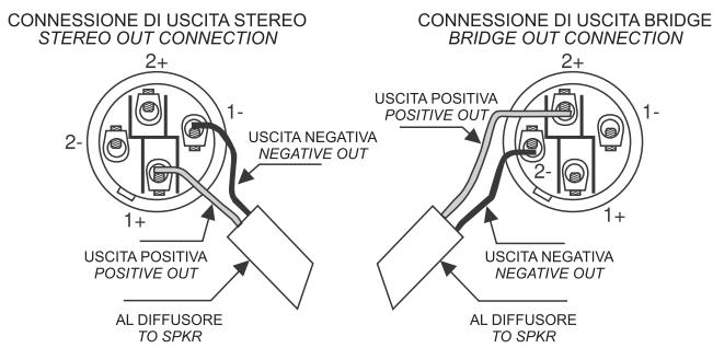
Speakon connectors are connected in parallel mode. One connector can be used to connect the box to the output of a power amplifier, the other to connect to a second box. Loudspeakers cables shall have the adequate diameter, depending on the overall length of the connection; the resistance introduced by an inadequate wiring towards the loudspeakers would reduce both the power output and the damping factor of the loudspeakers.
POWER AMP OUTPUTS
CONNESSIONE DI USCITA STEREO
STEREO OUT CONNECTION

CONNESSIONE DI USCITA BRIDGE
BRIDGE OUT CONNECTION


MUSE
210LA / 210LAV

- PRESET: to choose among 8 presets each one corresponding to a system configuration, according to the number of speakers in use, and to their angle (see PRESET section).
• LEVEL: adjust the level of the internal amplifier. - HF LEVEL: this control corresponds to a HIGH SHELVING filter, aimed to provide the system with a frequency response as even as possible through the whole listening area. The HF LEVEL control is extremely useful, and can be used in two ways:
- AMPLITUDE SHADING: top speakers are generally configured with the HF LEVEL set at -dB, whereas central ones are generally set at 0dB, and bottom ones closer to the audience at -dB. This serves to compensate for the atmospheric attenuation of acoustic waves, which is significant at high frequencies. It is also used to avoid discomfort for those people in the audience standing close to the system, which may be due to the extremely high energy of treble frequencies.

- TOGETHER WITH THE PRESET: in small systems consisting of 2, 3 or 4 speakers per side, users can adjust the balance of tones by acting on the HF LEVEL control while selecting one of the A-B-C presets.
- GND LIFT: switch to isolate the chassis ground and the signal ground to avoid ground loops, which can cause hum problems.
• ON: indicates that the system is on. - HP FILTER: this switch activates the low-cut filter which lets only the frequencies above the cut-off frequency pass at the output.
- PEAK: when this led lights up indicates that the signal is reaching saturation.
- LMT/PRT: if this led lights up there is a system malfunction due to an internal amplifier failure or to the intervention of current limiting circuits against thermal overload.
- IN/LINK: balanced input/output sockets: "IN" allows to connect a pre-amplified signal such as that coming, for instance, from mixer output. "LINK" allows to connect multiple speakers to the same signal.
A) 1 to 3 SPKR 0° to 4°
B) 2 to 3 SPKR 5° to 10°
C) 4 to 6 SPKR 0° to 4°
D) 4 to 6 SPKR 5° to 10°
E) 7 to 10 SPKR 0° to 4°
F) 7 to 10 SPKR 5° to 10°
G) 11 to 16 SPKR 0° to 4°
H) 11 to 16 SPKR 5° to 10°
NOTE | FOR PRESET CHOICE USERS MUST KNOW THE NUMBER OF SPEAKERS TO BE CONFIGURATED.
Each preset is identified by a letter (A to H) and also indicates the (maximum and minimum) number of speakers and the relevant angle.
- A) 1 to 3 SPKR 0° to 4°: when the system includes 1, 2 o 3 speakers and the angle between them is 0° e 4°.
- B) 2 to 3 SPKR 5° to 10°: when the system includes 2 o 3 speakers and the angle between them is 5° e 10°.
- C) 4 to 6 SPKR 0° to 4°: when the system includes 4, 5 o 6 speakers and the angle between them is 0° e 4°.
- D) 4 to 6 SPKR 5° to 10°: when the system includes 4, 5 o 6 speakers and the angle between them is 5° e 10°. Eg: If the system consists of 6 speakers, and the angles (between them, from top to bottom) are: 0°, 2°, 4°, 6°, 8°, 10°; preset “C” is set for the first three speakers, while preset “D” is selected for last three speakers (with 6°, 8°, 10° inclination).
- E-F-G-H): see the description of preset C and D, with a different number of speakers.

MUSE
210LA / 210LAV
The example of pic.1 shown a system with 6 MUSE 210LA speakers in vertical array.

NOTE | As the number of array elements increases, bass frequencies add up in all directions, since single modules are not directional at these frequencies. At high frequencies, instead, each speaker is extremely directional and, actually, there is poor interaction between speakers. Each preset corresponds to a different equalisation curve in order to obtain a constantly flat and balanced frequency response as the number of speakers included in the array increases, compensating for this change. In presets A to H, the equalisation programmed in the DSP tends to cut bass and boost treble frequencies, to put it simply. Obviously, each system configuration should correspond to a specific equalisation curve in order to obtain the same response in a certain listening point. Since the number of presets is limited, each group of configu-
rations is associated to a preset. This necessarily creates a border zone where both adjacent presets can be set to obtain the best system performance. This is why users shall consider preset settings as a suggestion by the manufacturer, a starting point, not a limit to their experiments. Since there are infinite possible system configurations and environments where sound can be spread, choosing the best preset will be the responsibility of the user.
If users are experienced enough and equipped with the proper mixer console measurement tools, they can leave preset A selected, and carry out system equalisation through an external digital loudspeaker management device, such as FBT DLM26 or FBT QUBE SP27.
XLR connections
The XLR connection is a type of balanced connection that allows the connection of devices over long distances without loss of quality due to the background noise detected. This is made possible by the presence, as well as by the mass (pin 1), of two cables: a signal cable (pin 2) and a 180° dephased signal cable (pin 3); at the opposite end of the signal source, on both these cables, in addition to the actual signal, the same quantity and type of background noise possibly detected along the path or inevitably produced by the cables (not the one for thermal agitation) will be present in phase. The signal will then be taken from the two cables by difference: in this way the useful part will be double amplitude while the noise detected or produced along the path, being present in phase on both cables, will be cancelled by the difference operation. In the three-pin version it is normally used for the termination of balanced audio lines but it is often also used for unbalanced signals creating a short circuit between the mass and the cold pin. The EIA RS-297-A standard requires that the three-pin XLR connectors for balanced audio are wired as shown in fig.

NOTE | SPEAKON is a registered trademark of NEUTRIK

Speakon
Speakon connectors are connected in parallel mode. One connector can be used to connect the box to the output of a power amplifier, the other to connect to a second box. Loudspeaker cables shall have the adequate diameter, depending on the overall lenght of the connection. The resistance introduced by an inadequate wiring towards the loudspeakers would reduce both the power output and the damping factor of the loudspeaker. Speakon is a connector which is specially adapted for connecting power terminals to loudspeakers; when inserted in an appropriate socket it locks so as to prevent accidental disconnection; moreover, it is equipped with protection against electrical shocks and guarantees correct polarisation.
Jack
The Jacks are typical connectors for the transporting of two separate signals through two channels, left and right, using a single connector and therefore they can be either mono or stereo. Mono jack (TS) also known as unbalanced jacks, are recognisable from stereo or balanced jacks (TRS) by their composition. The point of the mono jacks is divided into two parts, tip and ground (Tip and Slave) to which the two poles are connected; the stereo or balanced jacks are divided in three parts, as they have a central ring (Ring) which is connected to a second wire, the third (negative) pole.


MUSE
210LA / 210LAV
Power supply 230V
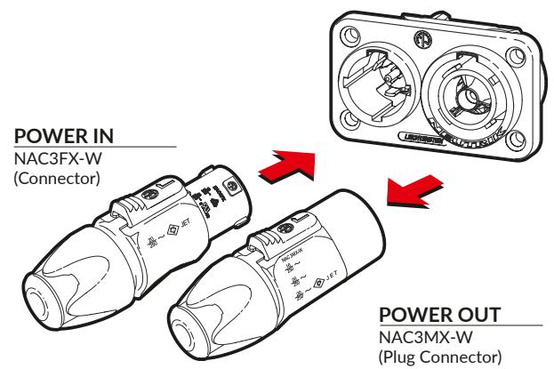
For power supply MUSE model features a Neutrik PowerCon THRU 1 with input and output.

CAUTION | Never replace the plug of the power cord supplied since the er cord can only support a maximum current of 16A.
Power supply 120V
If the total current demand does not exceed 15A use the power cable supplied. If the total current demand is between 15A and 20A user the power cable AWG12 SJT VW1 with plug rated current equal or greater than 30A.
THE CABLE AND THE PLUG MUST HOLD THE "UL" OR "CSA" CERTIFICATION.
The “POWERCON TRUE 1” system is certified as connector with breaking capacity according IEC 60320, VDE 0625. It is intended for use as appliance couplers and interconnection couplers. It serves to supply power to an appliance and from an appliance to another equipment. To be installed by qualified person only.

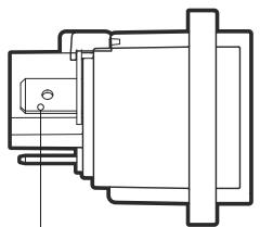
Flat tabs for FASTON®
6.35mm × 0.8mm
(1/4" × 0.03")
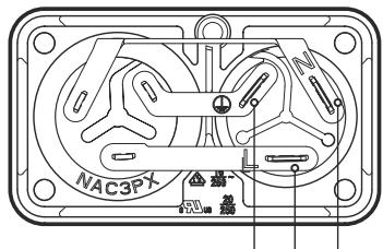
⊥ L N
MUSE
210LA / 210LAV
220 - 230V
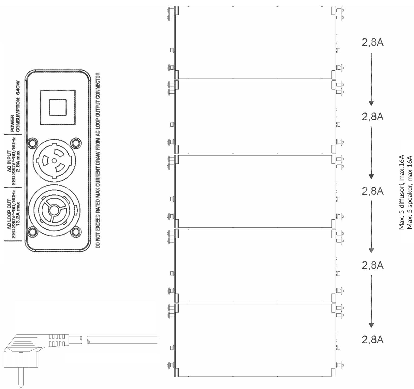
Max. 5 diffusori, max.16A
Max. 5 speaker, max 16A
MUSE
210LA / 210LAV
100 - 120V

Max. 2 diffusori, max.12A
Max. 2 speaker, max 12A

MUSE models feature a suspension system embedded in the bearing structure. The only element to be added (accessories) to realize complete arrays is the flybar model MS F21O; the suspension bar can also be used in a stacking configuration as ground support of the satellites above the subwoofer or as support of the system directly to earth.
⚠ WARNING | The use of different fixing accessories may cause a dangerous instability with possible damage to persons or things.
MUSE sound speaker must be installed using the flying accessories described in this manual and following the special assembly instructions by qualified staff only, strictly complying with the current regulations and safety standards in farce in the country of installation.
- FBT flying accessories are manufactured for their exclusive use with MUSE 21OLA system and have not been designed for being used with any other speaker or device.
- Any possible elements of the ceiling, floor or further supports where MUSE system is to be installed shall be able to safety bear the load.
- The flying accessories in use are to be coupled and secured safety to both the sound speaker and the ceiling (or the other support).
- When components are fitted to ceilings, floors or beams, always make sure that all couplers and fixing elements are properly sized and have an adequate load capacity.
- Besides the main suspension system, all flying speakers in theatres, indoor stadiums or in several other work and/or leisure facilities shall be provided with an additional independent safety system with the adequate load capacity. Only steel cables and chains with certified load capacity can be used as an additional safety device.

MS-F 210
Flying Bar
Code: 38834
686 x 100 x 652mm
27 x 3.93 x 25.66 inch
30 kg / 66.13 lb

MS-T 210
Trolley with Wheels
Code: 38886
722 x 182 x 500mm
28.42 x 7.18 x 19.68inch
14 kg / 30.86 lb

MS-J 210
Metal Joint
Code: 39401
∅100 x 92mm
∅3.93 x 3.62inch
0.50 kg / 1.10 lb

MS-C 210
Rain Cover
Code: 39340
0.50 kg / 1.10 lb
VERTICAL ARRAY system assembly guide
The configurations suggested by this manual were verified through computer modelling and operational testing; even in recommended configuration, before hanging any MUSE system check the relevant load limits.
Special attention was paid to the selection of the materials and manufacturing so as to permit high safely levels. The staff in charge of hanging the array system must be skilled and qualified; the installer/user will be responsible of ascertaining limits and lifting procedures for the structures to which the array will be attached. An improper use of the array suspension system may cause major damage to person and things.
Operations to be carried out:
- Inspet the hanging matrerial before every use.
- Observe all laws, local and national regulations about safety of installations.
- Hang the system to the attachment position indicated in the manual.
• Use skill staff only. - Ensure all locking devices are perfectly fitted.
- Ensure the capacity of lifting points and devices is greater than the load to be lifted.
Operations to avoid:
- Do not hang anything before reading the manual.
• Do not use unskilled stadd.
• Never exceed load limits. - Do not use non original spare parts.
• Do not use damaged or worm materials.
The MUSE system complies with the EN 60065 safety standard for audio, video and similar equipment.
⚠ WARNING | FBT accepts no responsibility for any damage to people or objects if these instructions are not complied with or if the safety factor of all elements related to system suspension are not properly checked.
⚠ WARNING | FBT will also place at your disposal a software which helps calculating the safety factor of the weakest point of unit suspension system according to the used configuration.
Follow this steps for a correct installation:
- Use the EASE FOCUS software to simulate the configuration suitable for the environment where the sound is to be reproduced considering SPL intensity and distribution in the audience.
- With the mechanical configuration parameters obtained, calculate the safety factor of unit suspension system.
- Check that the safety factor calculated falls within the range allowed by the standards and safety regulations in force in the country of installation.
- Should the safety factor to be lower or incompatible with the one required by current regulations, the installation is not allowed. Therefore, system size or inclination angles have to be changed, and sound simulation and safety checks are to be carried out again.
EASE FOCUS it is a software that permits an accurate simulation of the mechanical and acoustic behaviour of the line array system. The simulation algorithm is based on measurement taken on single modules; it is possible to set the number of areas for sound reproduction, the number of speakers, angles and levels relating to speakers and simulation parameters. It is also possible to check the attachment position of the flybar and the anchoring points of the system in relation to the maximum loads allowed. The software is an instrument that allows to immediately choose the best system configuration and proves suitable for both the experienced installer and the less experiendec user thanks to its automatic calculation feature. The software is available for download at AFMG website: focus.afmg.eu. EASE FOCUS acoustic model for the MUSE system is available on FBT website: www.fbt.it.
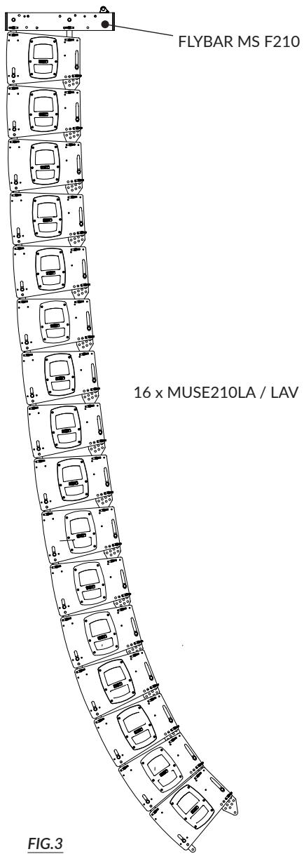
All flying accessories have been designed to guarantee maximum safety factor of 4:1 even for installations with 16 (maximum number) MUSE 210LA speakers (fig.3)
Should local regulations require a safety factor >4:1, system dimensions must be checked, or inclination angles changed, and acoustic simulations and safety checks must be repeated. MUSE systems may both flown and laid on the ground. System mounting type depends on the acoustic environment that needs being created and on the imposedassembly constraints. In the majority of common applications it is better to hang the system since this guarantees a more homogeneous coverage of the listening area. Every time the area for sound reproduction is located at a single level below an available attachmentpoint and extends over a certain lenght, system suspension is the best solution because it permits to better distribute the sound pressure over the whole area where sound is reproduced
NOTE | During installation, make sure that system bearing framework is included in the calculation of the total weight, as well as the MS-F 210 flybar, hoist chain, motors, cables and any additional weight.
WARNING | Should the above safety regulations and calculations of the overall weight fail to be complied with, FBT Elettronica will not liable for any damages to persons and things.

Hooking device for lifting operations
The hookking device for system lifting is asymmetrical and two different positions are possible (A and B). These two positions allow to move the device and, consequently, it change system angle at intermediate steps, by using the same fixing holes. Put the hooking device in the position suggested by the pointing software EASE FOCUS.

A

B

⚠ WARNING | For the accesory MS-F 210, it is considered that the admissible operating load is equal to 610kg and maximum configuration can be one of the following:
| C001 | C002 | C003 | C004 | C005 | C006 | C007 | C008 | C009 | |
| MUSE 210 | 16 pcs | 15 pcs | 14 pcs | 13 pcs | 12 pcs | 11 pcs | 10 pcs | 9 pcs | 8 pcs |
| MUSE 118 | 0 pcs | 0 pcs | 1 pcs | 1 pcs | 2 pcs | 2 pcs | 3 pcs | 3 pcs | 4 pcs |
| C010 | C011 | C012 | C013 | C014 | C015 | C016 | C017 | |
| MUSE 210 | 7 pcs | 6 pcs | 5 pcs | 4 pcs | 3 pcs | 2 pcs | 1 pcs | 0 pcs |
| MUSE 118 | 4 pcs | 5 pcs | 5 pcs | 6 pcs | 6 pcs | 7 pcs | 7 pcs | 8 pcs |
* The element is verified in reference to the Machinery Directive 2066/42/EC.

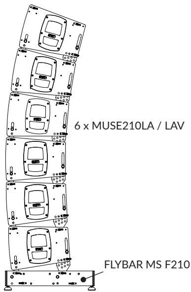
VERTICAL ARRAY installation
- Hook the speaker to the flybar using the four couplings (2 on each side).

- Fix the couplings onto the speaker by using the fixing pins.

- By using the (A) pin, the connecting flange can be moved, reaching the desired angle, also shown in the slot with the graduate scale. Fix the connecting flange by fitting the fixing pin in the relevant hole indicating the mselected angle.
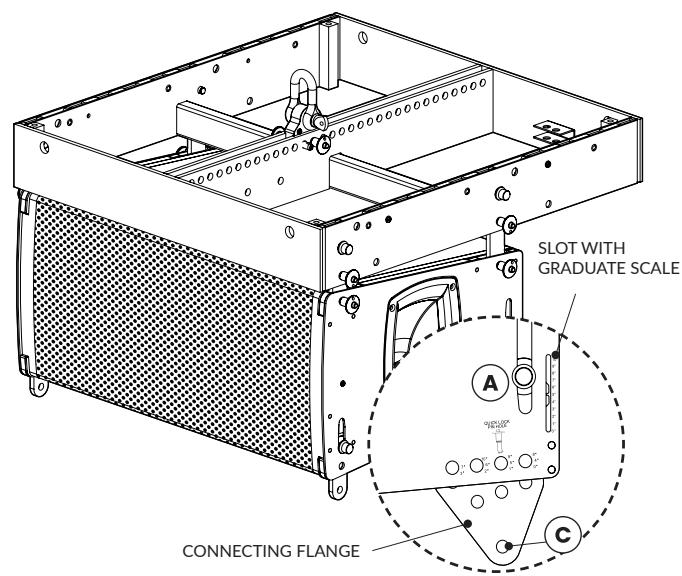
- Fix the speakers to each other using the relevant fixing pin. use (B) couplings for the front, and the connecting flange in point (C) for the back.

GROUND STACKING installation
1.
Fix the MS-J 210 on the stand support flange of the subwoofer.
i NB | This accessory can be fixed on the speaker installed both horizontally an vertically.


2.
Fix the MS-J 210 flybar onto the MS-J 210 accessory.


- Fit the satellite to the flybar by using the connecting flange (selecting the desired angle) and the front coupling.

RAIN COVER installation
Remove the six screws on speaker's back, put the cover on and fix it by means of the screws you removed.
⚠ WARNING | Under certain environmental condiopns, the rain cover may cause final amplifier overheating, triggering the protection circuit.

General
210L
210LA / 210LAV
| Configuration | way | 2 | 2 |
| Low frequency woofer | inch | 2 × 10 - 2.5 coil | 2 × 10 - 2.5 coil |
| High frequency driver | inch | 2 × 1 - 1.7 coil | 2 × 1 - 1.7 coil |
Acoustic Specifications
| Frequency response | (@-6dB) | 60Hz - 18kHz | 55Hz - 20kHz |
| Crossover frequency | kHz | External active | 1 |
| MAX SPL cont/peak bi-amp | dB | 128 / 135 | 128 / 135 |
| Dispersion | H x V | 90° x 10° - dependant upon n° of elements | 90° x 10° - dependant upon n° of elements |
| Sensitivity (@1W/1mt) | dB | 101 (LF) / 112 (HF) | --- |
| Recommended HP filter | Hz - dB / oct | 32 - 24 | --- |
| Recommended externalfilter | Digital management with preset | --- |
Amplifier
| Built-in amplifier cont. (LF / HF) | W RMS | --- | 400 (LF) / 200 (HF) |
| Built-in amplifier MAX (LF / HF) | W RMS | --- | 600 (LF) / 300 (HF) |
| Built-in amplifier MAX peak (LF / HF) | W | --- | 1200 (LF) / 600 (HF) |
| Recommended amplifier | W RMS | 800 (LF) / 200 (HF) | --- |
| Long term power | W | 400 (LF) / 100 (HF) | --- |
| Short term power (IEC 268-5) | W | 1600 (LF) / 400 (HF) | --- |
| Nominal impedance | Ohm | 16 (LF) / 32 (HF) | --- |
| Input impedance | kOhm | --- | 22 |
Power Supply
| AC power requirement | W | --- | 640 |
| Power cord | ft | --- | 22.96 |
Inputs & Outputs
| Input connectors | 2 x Speakon NL4 IN/OUT | XLR with loop |
Mechanical Specifications
| Material | Birch plywood 0.59" | Birch plywood 0.59" | |
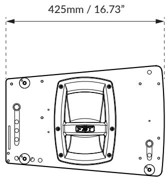
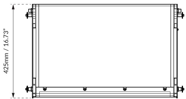
| Net dimensions (WxHxD) | inch | 25.66 x 11.65 x 16.73 | 25.66 x 11.65 x 16.73 |
| Transport dimensions (WxHxD) | inch | 20.87 x 31.89 x 15.35 | 20.87 x 31.89 x 15.35 |
| Net weight | lb | 83.33 | 84.87 |
| Transport weight | lb | 87.52 | 90.38 |
Product specifications

Packing specifications

Where affixed on the equipment or package, the barred waste bin sign indicates that the product must be separated from other waste at the end of its working life for disposal. At the end of use, the user must deliver the product to a suitable recycling centre or return it to the dealer when purchasing a new product.

Adequate disposal of the decommissioned equipment for recycling, treatment and environmentally compatible disposal contributes in preventing potentially negative effects on the environment and health and promotes the reuse and/or recycling of equipment materials. Abusive product disposal by the user is punishable by law with administrative sanctions.

Check the instructions of your municipality. Separate the components and disposal them properly.
AVOID RELEASE TO THE ENVIROMENT

SCAN FOR RECYCLING INFO
PLEASE FOLLOW YOUR AREA DISPOSITION
https://docs.fbt.it/filebrowser/share/l2CuWAX-
BOX
Corrugated Cardboard
PAPER DISPOSAL

PROTECTIONS
Expanded Polyethylene
PLASTIC DISPOSAL

PROTECTIONS
Expanded Polystyrene
PLASTIC DISPOSAL

BAGS
Low-density Polyethylene
PLASTIC DISPOSAL

MANUAL
Paper
PAPER DISPOSAL

FBT
FBT ELETTRONICA SPA
Via Paolo Soprani 1 - 62019 RECANATI - Italy
Tel. 071750591 - info@fbt.it - www.fbt.it


The information contained in this manual has been carefully checked; however, FBT does not accept any responsibility for possible inaccuracies. FBT Elettronica S.p.A. reserves the right to modify products and specifications at any time and without prior notice.
- DESCRIZIONE
- MUSE
- LA / 210LAV
- SPEAKON
- MS-F
- MS-T
- MS-J
- MS-C
- SAFETY PRECAUTIONS
- GENERAL FEATURES
- DIMENSIONS
- CONTROLS & FUNCTIONS
- PRESET
- INPUTS & OUTPUTS
- POWER SUPPLY
- ACCESSORIES
- MODE INSTALLATION
- TECHNICAL SPECIFICATIONS
- WASTE & DISPOSAL
- WARNING
- IMPORTANT SAFETY INSTRUCTIONS
- DESCRIPTION
- POWER AMP OUTPUTS
- NOTE | FOR PRESET CHOICE USERS MUST KNOW THE NUMBER OF SPEAKERS TO BE CONFIGURATED
- XLR CONNECTIONS
- JACK
- POWER SUPPLY 230V
- POWER SUPPLY 120V
- VERTICAL ARRAY SYSTEM ASSEMBLY GUIDE
- OPERATIONS TO BE CARRIED OUT
- OPERATIONS TO AVOID
- FOLLOW THIS STEPS FOR A CORRECT INSTALLATION
- VERTICAL ARRAY INSTALLATION
- GROUND STACKING INSTALLATION
- RAIN COVER INSTALLATION
- PRODUCT SPECIFICATIONS
- PACKING SPECIFICATIONS
- AVOID RELEASE TO THE ENVIROMENT
- SCAN FOR RECYCLING INFO
- BOX
- PROTECTIONS
- BAGS
- MANUAL
- FBT ELETTRONICA SPA
Brand : FBT
Model : 210L - 210LA - 210LAV