1081R - Audio Preamplifier AMS Neve - Free user manual and instructions
Find the device manual for free 1081R AMS Neve in PDF.


User questions about 1081R AMS Neve
0 question about this device. Answer the ones you know or ask your own.
Ask a new question about this device
Download the instructions for your Audio Preamplifier in PDF format for free! Find your manual 1081R - AMS Neve and take your electronic device back in hand. On this page are published all the documents necessary for the use of your device. 1081R by AMS Neve.
USER MANUAL 1081R AMS Neve
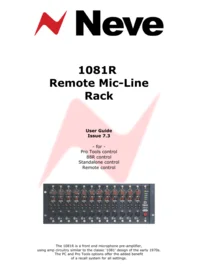
1081R
Remote Mic-Line Rack
User Guide
Issue 7.3
- for -
Pro Tools control
88R control
Standalone control
Remote control

The 1081R is a front end microphone pre-amplifier, using amp circuitry similar to the classic '1081' design of the early 1970s. The PC and Pro Tools options offer the added benefit of a recall system for all settings.
Table of Contents
Introduction....3
Dimensions....4
Power Requirements....4
Mains Power....4
Mains Fuse....4
Hot-Plugging....4
Unit Specifications....5
Microphone Module Spec and Description....5
Optional Mic/Line input Modules Spec and Description....5
Rack Housing Spec (fully fitted)....5
Connector Information....6
Audio Output Pin-outs....7
RS 485 I/O Connector....8
RS 232: K2 to 1081R cable pin-outs:....8
Encore to 1081R rack cable pin-outs:....8
USB to RS 485 pin outs....9
Comms Extension Cables....10
Installing the Software....11
Module Controls....13
Encore Control....14
88R Channel Strip Control....15
Standalone Computer Control....16
Software Setup....17
Pro Tools Control....18
Windows System Tray....20
Configuring Pro Tools Session....20
Head Office:
AMS Neve
Billington Road
Burnley
Lancs
UK
BB11 5UB
+44 (0)1282 417 311
Email: info@ams-neve.com
Web: www.ams-neve.com
Support: http://www.ams-neve.info/crm/fault_report.html
Introduction
The growing demand for high class 'front end' Mic pre-amplifiers has led to the release of the Neve 1081R standalone Microphone Rack providing the classic Neve microphone amplifier sound.
The microphone amplifiers may be controlled from:
• the front panel of the rack itself,
• an 88R console,
- a computer running AMS Neve's Remote Control Software, or
• from Pro Tools.
The computer and Pro Tools options offer the added benefit of a recall system for the Mic amp settings.
The Mic amp circuitry is very close to the classic '1081' design of the early 1970s using the same transformer, capacitor types and other components wherever possible.
The modules provide transformer balanced XLR Mic inputs to balanced line outputs via a multi way Varicon connector on the rear of the rack.

Twelve modules can be fitted into the 4U rack housing.
Each rack is also fitted with an intelligent control processor module and power supply.
In the unlikely even that this unit should malfunction or develop a fault, then please register the fault details on our website, by clicking the link below.
You will also need to enter the unit's serial number when you do this, so please have this to hand.
http://www.ams-neve.info/crm/fault_report.html
Once the fault details have been registered, one of our technical support team will be in touch via email.
This link should also be used for further operational or technical help, or any general enquiry about the unit.
Dimensions
| 19" Rack Mounting | U | Depth mm (inches) | Height mm (inches) | Approx weight kg (lbs) |
| Mic-Line Rack | 4 | 265 (10 1/2 ) | 178 (7) | 21m (46) * |
* Fully populated rack
Power Requirements
| Rated Voltage | 100 – 240V AC |
| Rated Frequency | 50 – 60 Hz |
| Rated Current | 0.5A Max |
| Earth Leakage Current | Approx 1.2mA |
| Warning for High Earth Leakage Current Required | NO |
| Primary Protection Fuse: | |
| Operating Voltage | 100 – 240V AC |
| Fuse Rating & Type | T 2A H 250V20mm x 5mm Ceramic(part number 190-047) |
| Location | IEC Mains connector |
| Secondary Protection Fuse: | |
| Output Voltage | 5V DC |
| Fuse Rating & Type | T 3 15A L 250V20mm x 5mm Glass |
| Location | FU1 on Processor |
Mains Power
The power supply unit is a universal input type therefore no mains operating voltage setting is required.
The CH (chassis) and 0V Link is permanently connected internally for stability.
Mains Fuse
The mains fuse is located in the IEC mains input connector on the rear of the unit.
Hot-Plugging
AMS Neve are not aware of any instances of hot-plugging modules causing a failure, however this procedure is not recommended.
The fuse for the 5V rails are located on the processor board, so removing and replacing this module will automatically force a power-up restart.
Unit Specifications
Microphone Module Spec and Description
| Microphone Input | XLR inputs, Zin 1Kohm @ 1kHzGain +20 to +70 in 5dB steps. |
| Maximum Input Level (with Pad in) | +24dB |
| Outputs | Max +26dB into 600 ohms.Z out 50 ohms +/-5% @ 1kHz, balanced. |
| Distortion | Not more than 0.07% for 20dBm output from 50Hz to 10kHz@60dB gain. |
| Microphone EIN | > -123dBm 20Hz to 20kHz @ 60dB gain. |
| Mechanical | 35mm x 158mm |
Optional Mic/Line input Modules Spec and Description
There are optional variants of the above modules which allow a line input to be switched into the circuit allowing a complete low impedance, line level feed from the rack to the console.
Line Input: Zin 50k ohm, unity gain, electronically balanced.
Rack Housing Spec
(fully fitted)
| Power | <40w, 100-240v auto sensing, 47-63Hz, 2A Anti Surge Fuse (fuse part number 190-047) |
| Mechanical | 4U x 19", 260mm deep. |
| Audio Interface | 12 balanced circuits on a 56 way panel mounted female Varicon. |
| Control Interface: | 2 x 9 Pin D Type 'Male' input and 'Female' output, RS485 format.(adapters required for serial RS232 or USB) |
Connector Information
Rear connectors are a 56 way Varicon connector for line outs and a pair of 9 pin D-type connectors for RS485 and a fused mains IEC socket.

On the front is a standard 3 pin female XLR Mic input per module.
The modules can be controlled locally via the front panel or remotely.
The control software will interrogate the racks and allow the user to specify modules to be controlled either locally OR from the control software.
By default, all modules power up with all functions controlled locally.
Settings are retained on power down.
Audio Output Connector Pin-outs
| Signal | Signal Name | Pin Number | ||
| Hi | Lo | Scn | ||
| 1 | Output 1 | C | J | D |
| 2 | Output 2 | P | V | K |
| 3 | Output 3 | U | Z | d |
| 4 | Output 4 | Y | c | f |
| 5 | Output 5 | s | m | j |
| 6 | Output 6 | x | t | n |
| 7 | Output 7 | CC | y | JJ |
| 8 | Output 8 | MM | HH | NN |
| 9 | Output 9 | B | F | A |
| 10 | Output 10 | L | R | E |
| 11 | Output 11 | S | W | a |
| 12 | Output 12 | X | b | e |
| 13 | --- | r | L | h |
| 14 | --- | v | p | k |
| 15 | --- | z | u | DD |
| 16 | --- | LL | EE | KK |
The "remote" functionality is provided either by a PC equipped with a RS232 interface or a USB port.
RS 232: K2 to 1081R cable pin-outs:

Most PC's are fitted with RS232 interfaces as standard and will therefore need to use the RS232 to RS485 converter (such as ones manufactured by K2 systems, shown left).
This is a female-to-female 9-pin converter that goes between the rack and the PC.
The K2 to 1081R rack cable is not wired one-to-one, it is wired with a 9 pin D-type male connector at both ends.
It is important that the cable is installed the right way round.
| Signal | 1081 Rack (male) | K2 (male) |
| Data - | 1 | 3 |
| Data + | 6 | 8 |
| Ground / Screen | 7 | 1 |
The switch settings for the K2 converter are:
| SW 1 | ON | RS 485 |
| SW 2 | ON | Always Receive |
| SW 3 | OFF | Transmitter controlled by RTS |
| SW 4 | OFF | RTS Control |
| SW 5 | OFF | RTS Control |
| SW 6 | OFF | RTS Control |
Encore to 1081R rack cable pin-outs:
The Encore to 1081R rack cable will be wired with a 9 pin D-type female at the Encore end and a 9 pin D-type male at the 1081R rack end.
| Signal | 1081 Rack (male) | Encore PC (female) |
| Data - | 1 | 1 |
| Data + | 6 | 6 |
| Ground / Screen | 7 | 7 |
If preferred, a USB to RS485 converter can be used on computers that do not have a 9-pin connector.
A standard USB cable connects the PC and the converter.
USB to RS 485 pin outs
| Signal | 1081 Rack (male) | RS 485 converter (female) |
| Data - | 6 | 1 |
| Data + | 1 | 2 |
| Ground | 7 | 5 |
We recommend the following USB to serial RS 422/485 converter:
http://www.easysync-ltd.com/product/544/es-u-2101.html

AMS Neve has tested this converter and found it to be the most suitable on the market.
We therefore cannot guarantee that similar products by different manufacturers will be as reliable.
Comms Extension Cables

The 1081R rack RS485 Input and Output connectors are wired in parallel with the exception of the ground.
The Input connector is a 9 pin D-type female while the Output connector is a 9 pin D-type male.
This is to allow the connectors to be joined together in the event of a rack needing to be removed from the daisy-chain.
The ground pin on the Input connector is not a direct connection to ground to prevent ground loops.
Care should also be taken when selecting which cable is to be used for communications, especially for long (20m+) runs as marginal cable can cause intermittent problems which can prove difficult to troubleshoot.
The RS-422 specification recommends 24AWG twisted pair with a shunt capacitance of 16pF per foot and a 100 ohm characteristic impedance.
It can be difficult to determine whether shielding is required until problems arise, so we recommend using shielded cable.
A good choice is Ethernet cable, commonly called Category 5 cable.
This is defined by the EIA/TIA/ANSI 568 specification, has a maximum capacitance of 17pF per foot and a characteristic impedance of 100 ohms.
It is available as either Shielded Twisted Pair (STP) or Unshielded Twisted Pair (UTP) and generally exceeds the recommendations for RS-422 protocol.
The racks can be "daisy chained" to provide up to 192 remote controllable Mic amps. This is achieved using a maximum of 16 racks daisy chained, each with the full 12 module slots populated.
The last rack in the chain should have a terminator fitted, with a 120Ω resistor across pins 1 & 6 of a 9 pin female D-type:
Installing the Software
The install procedure is the same install regardless of whether the software is installed on a standalone PC or on a Pro Tools PC.
Double click the Setup icon, and the install will begin.

▶ Click Next.

▶ Click I Accept The Agreement.
If you select I Do Not Accept The Agreement, the software will not be installed and install will terminate.

▶ Click Next.

▶ Click Next.

▶ Click the options if you wish to have a Desktop Icon or a Quick Launch Icon for the application installed.
▶ Click Next.
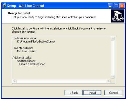
▶ Click Install.

The software will install.
▶ Click Finish.
(If you wish to launch the programme, click Launch Mic Line Control before clicking Finish).
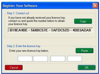
The programme requires a licence key supplied by AMS-Neve, and you will be asked to enter this the first time the programme is launched.
The 32-digit string of characters shown on the upper half of the screen is unique to every PC, so a different password will be required for every PC the programme is installed on.
▶ Please contact AMS-Neve Sales Dept to get your password quoting this string, as your password will be generated from this.
▶ Once you have the password, type it into the 4 boxes shown and click OK. You will only have to enter this password once.
If the password is valid, the software will now be ready to use.

Module Controls

The modules can be controlled from their front panels, an 88R console, or from a remote PC or Pro Tools using the optional Remote Control Software.
By default all modules power up with all functions locally controllable and settings are retained on power down.
Front panel control of the Mic amplifiers allows the amplifiers to be set up from the studio floor and also allows a method of control if for any reason the control computer system should fail. The rack will normally power up in this mode and will also revert to this mode if the serial control from the computer is lost.
Front panel control is available for48V, Pad and Phase control. These functions are active once the internal led is green.
Turning the switched Gain control will vary the gain as shown in the display beneath, but the gain is not related to the actual position of the knob, which will infinitely rotate.
The range of control is from +20dB to +70dB in 5dB steps.
Next to the gain control are two LEDs that indicate signal presence (at approximately -30dBu or greater) and signal overload (at 2dB below clipping).
The 48V, phase and -20 switches control the phantom power, phase and pad functions respectively.
The DIR button is a relay bypass that connects the front panel XLR directly to the rear panel Varicon and hence to the console patch without going through the remote Mic amp's audio electronics.
This allows the Mic to be used even if there is a complete failure of the remote rack.
The Line In option uses the DIR button to switch from transformer balanced microphone input to electronically balanced Line Input.
If using in conjunction with an 88R console, front panel control allows the amplifiers to be set up from the studio floor and also allows a method of control if for any reason the Encore system should fail.
Control is either from the module front panel, or from the channel strip but not from both.
This is to prevent the module from having different settings to those set on the channel strip.
If the module is not assigned to a channel module, it can still be controlled from the Encore screen at the same time as from the front panel, the Encore screen will reflect changes made at the front panel.
Encore Control
The AMS Neve mic amp control software can be launched either from the System menu within the Encore automation program, or directly from the Start Programs function of Windows.
The control program automatically detects the presence of connected mic amp racks and will display the number, type and position of all detected modules within the selected rack.
The icons at the bottom of the screen indicate how many remote racks are connected and the rack indicated by the red outline is the one currently being controlled from the upper part of the screen.

If attached to an 88R console, the remote mic amplifiers can be individually assigned to 88R channel strips for control using the channel selector, or they can be controlled directly from the screen (but not both together).
Whatever the control method, the screen shows the current settings.
The mic amp settings can be saved and recalled independently of the console's recall system using the Save and Load buttons that launch conventional Windows dialogues.
88R Channel Strip Control

After Encore has assigned a remote mic amp module to a channel strip, the channel strip controls can be used to control the remote mic amp.
Please make sure that the mic amp output is patched to the channel line input that Encore has assigned the remote mic module to, and that the channel is switched to Line input (for example, that the C/O switch is in when the console status is in Record mode).
To ensure that the overload indicators on the channel correspond to the overload point of the remote mic amplifiers, set the line input trim on the channel strip to zero.
The mic gain control on the channel module is continuous when controlling the internal mic amplifier, but will cause the remote mic amplifier gain to change in steps of 5dB (as indicated on the Encore screen and remote mic amp module).
The remote mic amp gain control may use the same value from the channel strip gain control that Encore's Recall system uses, so Encore's Recall system will always restore the mic amp gain to the correct value, regardless of gain control component variations.
The pad and phantom power switches on the channel strip will control these functions on the remote mic amplifier, but the phase switch will not control the phase of the remote mic amplifier. This is because a phase reversal in the remote mic amp would cancel out the simultaneously selected phase reversal on the line input of the channel module.
To set the remote phase reversal instead of the channel strip phase reversal use the button on the Encore screen.
Standalone Computer Control

The Remote Control Software is installed by running Setup.exe. Please see the Installing The Software section of this document.
After installation the software can be launched from the Windows Start menu / Programs / Mic Line Control / Mic Line Control.
The control program automatically detects the presence of connected Mic amp racks and will display the number and position of all detected modules within the selected rack.
The screen will be updated with any changes made through the modules' front panels. The screen is also used to remotely control the mic amps.
The Gain can be set by selection from the drop-down settings list. The Phantom, Pad, Phase and bypass (DIR) settings can be toggled by clicking on the appropriate button.
The icons at the bottom of the screen indicate how many remote racks are connected. The rack indicated by the red outline is the one currently being controlled from the upper part of the screen.
The Mic amp settings can be saved and recalled independently using the Store Preset and Load Preset buttons that launch conventional Save and Load Windows dialogues.
Software Setup

Before using the software for the very first time, the comms port for the serial cable must be set from the Setup page.
This is normally COM2, COM3 or COM4 as the mouse is on COM1.
If the port is incorrectly set, the software will fail to find the RS485 adapter and will report an error.
For more information, please see your Windows documentation.
Once the racks have been found by the software (as shown left by the software version being displayed against Rack #2), the communication link to each rack can be tested with the Test buttons.
This will cause the yellow Comms indicator on the front panel of the remote rack processor module to flash briefly.
This is useful for checking that each rack has been set to its own unique address - ie that only one rack's led flashes.
The rack addresses are set by sixteen dip switches on the remote rack processor module.
When multiple racks are connected to a PC or Pro Tools system, each processor module has to have a unique switch setting so each rack can be addressed individually.
For example, switch 1 on the rack 1 processor card, switch 2 in rack 2, switch 3 in rack 3 etc.
In normal operation the comms indicator will be pulsing so fast as to appear constantly lit.
Resetting a rack (or all the racks) from the Setup page, will clear the control settings back to their default values.
This action is performed when the Setup page is subsequently exited, not when the button is clicked.
MIDI Port Setup is covered in the following chapter.
The Create de-bug file check box is for R&D and Technical Services personnel use only.
Setting the Auto Load option on will cause the last saved or loaded system setup to be reloaded when the software is next started.
This option is interlocked with the Auto Restore Previous Setup on Startup option, which will restore the settings of the rack as they were when the system was powered down.
Pro Tools Control

Control is sent and received between the 1081R rack and Pro Tools via MIDI cables or over a local network.
It is necessary that a suitable driver is installed such as the MIDIOverLAN driver available from www.nerds.de.
For more information, please click on the above link.
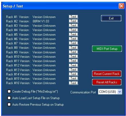
Open the Mic.exe application. This will either appear as an icon on the desktop, or can be accessed via Start menu / Programs / Mic Line Control / Mic Line Control.
On the main page, click Setup, and the Setup/Test screen will open.
Click MIDI Port Setup.

In both upper displays, click the MIDI In and MIDI Out you wish to select, then click Link Ports.
The linked Ins and Outs will appear in the lower window. Repeat for as many midi ports you wish to link.
In the lower window, tick each pair of ports you wish MIDI data to be sent over, then click Start Midi. The entries on screen will be greyed out confirming that midi data is being sent and received. These Midi streams must match those set in Pro Tools.
If you need to set further links (or use the Remove button to cancel links), you will need to click Stop MIDI before doing this. Click OK, and you will be returned to the Setup screen.

Once midi is running, the Setup screen will show two further buttons. Click on MIDI Pre Setup.

The Pre MIDI Port Setup screen will open, showing the (up to) 9 available Pro Tools racks.

Click the Auto-Detect button. Two warning screens will be displayed:
Click OK to both of these and the mapping procedure will take place.
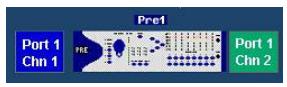
Midi ports will be mapped to the available racks and displayed, colour coding the IN and OUT fields:
| Red | Unavailable Input |
| Blue | Available Input |
| Green | Available Output |
Click Exit and return to the Setup / Test page.

Click MIDI Rack Setup and the rack display page will open.

To allow all the modules to be addressed, the channels are allocated in groups of 4, so that one rack requires one and a half midi channels to be fully controlled.
Even if there is only a single module in any group of a rack, the display will show that group as being fully populated, allowing it's address to be set.
If there are thirds of a rack where there are no modules, then the display will indicate a blank panel, as shown left.
Only racks that are physically present will be displayed.
Clicking the Default button will reset all of their racks to their default values.

Right-click on each group of each module, to get a fly-out menu that allows the address of each block of 4 modules to be set.
A is channels 1 to 4, B is 5 to 8 etc.

When all parameters have been set correctly, the colour-coded mapping will be displayed on the main Mic programme page.
It is also possible to right-click on each coloured bar and remap each segment manually, as shown left.
| PRE 1 |
| PRE 2 |
| PRE 3 |
| PRE 4 |
| PRE 5 |
| PRE 6 |
| PRE 7 |
| PRE 8 |
| PRE 9 |
Windows System Tray

Once the midi has been started, a green Neve icon will appear on the Windows System Tray.
Right-click this icon, to see 4 options:

Show MIDI Messages will open a screen displaying midi data that is being sent and received (left).
Any entry in red shows that the MIDI stream is not valid.
The Midi Messages screen is only available when the Setup screen is not being displayed.
Broadcast Current Setup will broadcast the current state of all midi setup 1081R racks across the network to Pro Tools (this includes Gain, Phase, Pad and Phantom Power)
Stop Midi and Exit are self-explanatory.
Configuring Pro Tools Session
Please refer to your Pro Tools documentation on how to configure your Pro Tools session.

- R
- REMOTE MIC-LINE RACK
- TABLE OF CONTENTS
- INTRODUCTION
- MAINS POWER
- MAINS FUSE
- HOT-PLUGGING
- UNIT SPECIFICATIONS
- OPTIONAL MIC/LINE INPUT MODULES SPEC AND DESCRIPTION
- RACK HOUSING SPEC
- CONNECTOR INFORMATION
- AUDIO OUTPUT CONNECTOR PIN-OUTS
- RS 232: K2 TO 1081R CABLE PIN-OUTS
- IT IS IMPORTANT THAT THE CABLE IS INSTALLED THE RIGHT WAY ROUND
- ENCORE TO 1081R RACK CABLE PIN-OUTS
- INSTALLING THE SOFTWARE
- MODULE CONTROLS
- ENCORE CONTROL
- R CHANNEL STRIP CONTROL
- STANDALONE COMPUTER CONTROL
- SOFTWARE SETUP
- PRO TOOLS CONTROL
- WINDOWS SYSTEM TRAY
- CONFIGURING PRO TOOLS SESSION
Brand : AMS Neve
Model : 1081R
Category : Audio Preamplifier