STWC - Lawn mower Scag - Free user manual and instructions
Find the device manual for free STWC Scag in PDF.


User questions about STWC Scag
0 question about this device. Answer the ones you know or ask your own.
Ask a new question about this device
Download the instructions for your Lawn mower in PDF format for free! Find your manual STWC - Scag and take your electronic device back in hand. On this page are published all the documents necessary for the use of your device. STWC by Scag.
USER MANUAL STWC Scag
THIS MANUAL CONTAINS THE OPERATING INSTRUCTIONS AND SAFETY INFORMATION FOR YOUR SCAG MOWER. READING THIS MANUAL CAN PROVIDE YOU WITH ASSISTANCE IN MAINTENANCE AND ADJUSTMENT PROCEDURES TO KEEP YOUR MOWER PERFORMING TO MAXIMUM EFFICIENCY. THE SPECIFIC MODELS THAT THIS BOOK COVERS ARE CONTAINED ON THE INSIDE COVER. BEFORE OPERATING YOUR MACHINE, PLEASE READ ALL THE INFORMATION ENCLOSED.

WARNING:
FAILURE TO FOLLOW SAFE OPERATING PRACTICES MAY RESULT IN SERIOUS INJURY.
* Keep all shields in place, especially the grass discharge chute.
* Before performing any maintenance or service, stop the machine and remove the spark plug wire and ignition key.
* If a mechanism becomes clogged, stop the engine before cleaning.
* Keep hands, feet and clothing away from power-driven parts.
* Read this manual completely as well as other manuals that came with your mower.
* Keep others off the tractor (only one person at a time)
Hazard control and accident prevention are dependent upon the awareness, concern, prudence, and proper training of the personnel involved in the operation, transport, maintenance, and storage of the equipment.
This manual covers the operating instructions and illustrated parts list for:
STWC52A-25KA
with a serial number of A8700001 to A8799999
STWC61A-27CV
with a serial number of A5600001 to A5699999
SMWC-52A
with a serial number of A5500001 to A5599999
SMWC-61A
with a serial number of A5700001 to A5799999
Always use the entire serial number listed on the serial number tag when referring to this product.
SCAG POWER EQUIPMENT®
TABLE OF CONTENTS
SUBJECT
PAGE
Section 1 - General Information
1.1 Introduction ...... 1
1.2 Directional Reference....1
1.3 Servicing the Engine and Drive Train Components .... 1
1.3 Symbols 2-3
Section 2 - Safety Information
2.1 Introduction 4
2.2 Signal Words 4
2.3 Before Operation Considerations 4
2.4 Operation Considerations .... 5
2.5 Roll Over Protection System (Optional) 6
2.6 Maintenance Considerations 8
2.7 Safety and Instructional Decals 9
Section 3 - Specifications ....10-11
Section 4 - Operating Instructions
4.1 Controls and Instrument Identification 12
4.2 Safety Interlock System 13
4.3 Initial Run-In Procedures 14
4.4 Starting the Engine 14
4.5 Ground Travel and Steering 14
4.6 Engaging the Deck Drive 15
4.7 Hillside Operation 16
4.8 Parking the Mower 16
4.9 After Operation 16
4.10 Removing Clogged Material 17
4.11 Moving Mower with Engine Stopped 17
4.12 Recommendations for Mowing 17
4.13 Adjusting Cutting Height 17
4.14 Towing 18
Section 5 - Troubleshooting Cutting Conditions....19-21
TABLE OF CONTENTS (CONT'D)
SUBJECT
PAGE
Section 6 - Adjustments
6.1 Parking Brake Adjustment 22
6.2 Travel Adjustments 23
6.3 Throttle Control and Choke Adjustments 24
6.4 Belt Adjustment 24
6.5 Belt Alignment 24
6.6 Cutter Deck Adjustments 25
Section 7 - Maintenance
7.1 Maintenance Chart 28
7.2 Lubrication Fitting Points 29
7.3 Hydraulic System 31
7.4 Engine Oil 32
7.5 Engine Fuel System 32
7.6 Engine Air Cleaner 33
7.7 Battery 33
7.8 Drive Belts 35
7.9 Cutter Blades 35
7.10 Tires 36
7.11 Body, Deck and Upholstery 36
Section 8 - Replacement Parts
Notes 37
STWC52A Cutter Deck 38-39
STWC61A Cutter Deck 40-41
Cutter Deck Controls 42-43
Sheet Metal Components 44-45
STWC Roll Over Protection System 46-47
Drive System Components 48-49
Engine and Attaching Parts - Kohler 50-51
Steering Components 52-53
Brake Components 54-55
Fuel and Hydraulic System 56-57
Electrical System 58-59
Hydraulic Pump (BDP-10A) 60-61
Replacement Decals 62-63
Electrical Schematic (Kohler & Kawasaki) 64
Warranty Statement ...... Following Illustrated Parts List
GENERAL INFORMATION
1.1 INTRODUCTION
Your mower was built to the highest standards in the industry. However, the prolonged life and maximum efficiency of your mower depends on you following the operating, maintenance and adjustment instructions in this manual.
If additional information or service is needed, contact your Scag Power Equipment Dealer.
We encourage you to contact your dealer for repairs. All Scag dealers are informed of the latest methods to service this equipment and provide prompt and efficient service in the field or at their service shop. They carry a full line of Scag service parts.
USE OF OTHER THAN ORIGINAL SCAG REPLACEMENT PARTS WILL VOID THE WARRANTY.
When ordering parts, always give the model and serial number of your tractor. The serial number plate is located where shown in Figure 1-1.

Figure 1-1 Tractor Serial Number Plate Location
USE ONLY SCAG APPROVED ATTACHMENTS AND ACCESSORIES.
Attachments and accessories manufactured by companies other than Scag Power Equipment are not approved for use on this machine.
Scag approved attachments and accessories:
GC-STC (p/n 9038)
GC-STC-CS (p/n 9040)
Mulch Plate (p/n 9260, 9261)
Hurricane Mulch (p/n 9265, 9266)
STC Hitch (p/n 9241)
STC - Lights (p/n 9274)
Tiger Striper (p/n 9269)
Blade Buddy (p/n 9212)

WARNING:
For pictorial clarity, some illustrations and figures in this manual may show shields, guards or plates open or removed. Under no circumstances should your mower be operated without these devices in place.
All information is based upon product information available at the time of approval for printing. Scag Power Equipment reserves the right to make changes at any time without notice and without incurring any obligation.
1.2 DIRECTION REFERENCE
The “Right” and “Left”, “Front” and “Rear” of the machine are referenced from the operator’s right and left when seated in the normal operating position and facing the forward travel direction.
1.3 SERVICING THE ENGINE AND DRIVE TRAIN COMPONENTS
The detail servicing and repair of the engine, hydraulic pumps and gearboxes are not covered in this manual; only routine maintenance and general service instructions are provided. For service of these components during the limited warranty period, it is important to contact your Scag dealer or find a local authorized servicing agent of the component manufacturer. Any unauthorized work done on these components during the warranty period may void your warranty.
ISO Symbols
CE
CE Mark
| SYMBOL | DESCRIPTION | SYMBOL | DESCRIPTION |
 | Choke |  | Transmission |
 | Parking Brake |  | Spinning Blade |
| On/Start |  | Spring Tension on Idler | |
| Off/Stop | Oil | ||
Falling Hazard | |||
 | Fast |  | Slow |
 | Continuously Variable - Linear |  | Cutting Element - Basic symbol |
 | Pinch Point |  | Cutting Element - Engage |
 | Hourmeter/Elapsed Operating Hours |  | Cutting Element - Disengage |
 | Thown Object HazardKeep Bystanders Away |  | Read Operator's Manual |
SAFETY INFORMATION
2.1 INTRODUCTION
Your mower is only as safe as the operator.
Carelessness or operator error may result in serious bodily injury or death. Hazard control and accident prevention are dependent upon the awareness, concern, prudence, and proper training of the personnel involved in the operation, transport, maintenance and storage of the equipment. Make sure every operator is properly trained and thoroughly familiar with all of the controls before operating the mower. The owner/user can prevent and is responsible for accidents or injuries occurring to themselves, other people or property.
READ THIS OPERATOR'S MANUAL BEFORE ATTEMPTING TO START YOUR MOWER.
A replacement manual is available from your authorized Scag Service Dealer or by contacting Scag Power Equipment, Service Department at P.O. Box 152, Mayville, WI 53050 or via the Internet at www.scag.com. The manual for your machine can be downloaded by using the model and serial number or use the contact form to make your request. Please indicate
the complete model and serial number of your Scag product when requesting replacement manuals.
2.2 SIGNAL WORDS

This symbol means “Attention! Become Alert! Your Safety is Involved!” The symbol is used with the following signal words to attract your attention to safety messages found on the decals on the machine and throughout this manual. The message that follows the symbol contains important information about safety. To avoid injury and possible death, carefully read the message! Be sure to fully understand the causes of possible injury or death.
Signal Word:
It is a distinctive word found on the safety decals on the machine and throughout this manual that alerts the viewer to the existence and relative degree of the hazard.

DANGER:
The signal word “DANGER” denotes that an extremely hazardous situation exists on or near the machine that could result in high probability of death or irreparable injury if proper precautions are not taken.

WARNING:
The signal word “WARNING” denotes that a hazard exists on or near the machine that can result in injury or death if proper precautions are not taken.

CAUTION:
The signal word “CAUTION” is a reminder of safety practices on or near the machine that could result in personal injury if proper precautions are not taken.
Your safety and the safety of others depends significantly upon your knowledge and understanding of all correct operating practices and procedures of this machine.
2.3 BEFORE OPERATION CONSIDERATIONS
- NEVER allow children to operate this riding mower. Do not allow adults to operate this machine without proper instructions.
- DO NOT mow when children and/or others are present. Keep children out of the mowing area and in the watchful care of a responsible adult other than the operator. Be alert and turn machine off if a child enters the area.
- Clear the area to be mowed of objects that could be picked up and thrown by the cutter blades.
- DO NOT carry passengers.
- DO NOT operate the machine under the influence of alcohol or drugs.
2.3 BEFORE OPERATION CONSIDERATIONS (CONT'D)
- If the operator(s) or mechanic(s) cannot read English or Spanish, it is the owner's responsibility to explain this material to them.
- DO NOT wear loose fitting clothing. Loose clothing, jewelry or long hair could get tangled in moving parts. Do not operate the machine wearing shorts; always wear adequate protective clothing including long pants. Wearing safety glasses, safety shoes and a helmet is advisable and is required by some local ordinances and insurance regulations.
- Operator hearing protection is recommended, particularly for continuous operation of the mower. Wear suitable hearing protection. Prolonged exposure to loud noise can cause hearing impairment or loss.
- Keep the machine and attachments in good operating condition. Keep all shields and safety devices in place. If a shield, safety device or decal is defective or damaged, repair or replace it before operating the machine.

WARNING:
This machine is equipped with an interlock system intended to protect the operator and others from injury. This is accomplished by preventing the engine from starting unless the deck drive is disengaged, the parking brake is on, the steering control levers are in the neutral position and the operator is in the seat. The system shuts off the engine if the operator leaves the seat with the deck drive engaged and/or the steering control levers are not in the neutral position and/or the parking brake is not engaged. Never operate equipment with the interlock system disconnected or malfunctioning.
- Be sure the interlock switches are functioning correctly.
-
Fuel is flammable; handle it with care. Fill the fuel tank outdoors. Never fill it indoors. Use a funnel or spout to prevent spillage. Clean up any spillage before starting the engine.
-
DO NOT add fuel to a running or hot engine. Allow the engine to cool for several minutes before adding fuel.
- Keep flammable objects (cigarettes, matches, etc.), open flames and sparks away from the fuel tank and fuel container.
- Equipment must comply with the latest requirements per SAE J137 and/or ANSI/ASAE S279 when driven on public roads.
-NOTE-
If the mower is driven on public roads, it must comply with state and local ordinances as well as SAE J137 and/or ANSI / ASAE S279 requirements. Contact your local authorities for regulations and equipment requirements.
- DO NOT operate without the side discharge chute installed and in the down position or with an optional grass catcher or mulch plate completely installed.
- Check the blade mounting bolts at frequent intervals for proper tightness.
- Make sure all hydraulic fluid connections are tight and all hydraulic hoses and lines are in good condition before starting the machine.
2.4 OPERATION CONSIDERATIONS
- Know the function of all controls and how to stop quickly.
- Reduce speed and exercise extreme caution on slopes and in sharp turns to prevent tipping or loss of control. Be especially cautious when changing directions on slopes.

WARNING:
DO NOT operate on steep slopes. To check a slope, attempt to back up it (with the cutter deck down). If the machine can back up the slope without the wheels slipping, reduce speed and use extreme caution. ALWAYS FOLLOW OSHA APPROVED OPERATION.
2.4 OPERATION CONSIDERATIONS (CONT'D)
- To prevent tipping or loss of control, start and stop smoothly, avoid unnecessary turns and travel at reduced speed.
- When using any attachment, never direct the discharge of material toward bystanders or allow anyone near the machine while in operation.
- Before attempting to start the engine, with the operator in the seat, disengage power to the cutter deck, place the steering control levers in the neutral position and engage the parking brake.
- If the mower discharge ever plugs, shut off the engine, remove the ignition key, and wait for all movement to stop before removing the obstruction.
WARNING:
DO NOT use your hand to dislodge the clogged discharge chute. Use a stick or other device to remove clogged material.
- Be alert for holes, rocks, roots and other hidden hazards in the terrain. Keep away from any dropoff. Beware of overhead obstructions (low limbs, etc.), underground obstacles (sprinklers, pipes, tree roots, etc.). Cautiously enter a new area. Be alert for hidden hazards.
- Disengage power to cutter deck before backing up. Do not mow in reverse unless absolutely necessary and then only after observation of the entire area behind the mower.
- DO NOT turn sharply. Use care when backing up.
- Disengage power to cutter deck before crossing roads, walks or gravel drives.
- Mow only in daylight or good artificial light.
-
NEVER raise the deck with the blades engaged.
-
Take all possible precautions when leaving the machine unattended, such as disengaging the mower, lowering the attachments, setting the parking brake, stopping the engine, and removing the key.
- Disengage power to the attachments when transporting or when not in use.
- The machine and attachments should be stopped and inspected for damage after striking a foreign object, and damage should be repaired before restarting and operating the machine.
CAUTION:
DO NOT touch the engine or the muffler while the engine is running or immediately after stopping. These areas may be hot enough to cause a burn.
WARNING:
DO NOT run the engine inside a building or a confined area without proper ventilation. Exhaust fumes are hazardous and could cause death.
- Keep hands and feet away from cutter blades and moving parts. Contact can injure.
- Use care when loading or unloading the machine onto a trailer or truck.
- Use care when approaching blind corners, shrubs, trees, or other objects that may obscure vision.
2.5 ROLL OVER PROTECTION SYSTEM
WARNING:
Seat belt must be securely fastened during operation. Failure to do so could cause serious injury or loss of life.
This mower has been designed for good traction and stability under normal mowing conditions. However, caution must be used when traveling on slopes, especially when the grass is wet. Do not mow on wet grass. Wet grass reduces traction and steering control.
Any or all parts of the Roll Over Protection System MUST NOT be removed. Failure to adhere to this guideline could result in injury or death.
The potential exposure of this seat belt to severe environmental conditions make it crucial to inspect the seat belt system regularly.
It is recommended that the seat belt be inspected on a daily basis for signs of damage. Any seat belt system that shows cuts, fraying, extreme or unusual wear, significant discoloration due to UV exposure, dirt or stiffness, abrasion to the seat belt webbing, or damage to the buckle, latch plate, hardware or any other obvious problem should be replaced immediately.

WARNING:
Failure to properly inspect and maintain the seat belt can cause serious injury or loss of life.
- Check the full length of the seat belt webbing for cuts, wear, fraying, dirt and stiffness. See Figure 2-1.
- Check the seat belt webbing in areas exposed to ultra violet rays from the sun or extreme dust or dirt. If the original color of the webbing in these areas is extremely faded and/or is packed with dirt, the physical strength of this webbing may have deteriorated. If this condition exists, replace the seat belt system.
- Check the buckle and latch for proper operation and determine if the latch plate is excessively worn, deformed, or of the buckle is damaged or cracked. See Figure 2-1.

Figure 2-1 Seat Belt Inspection

WARNING:
Reduce speed when turning, operating on slopes, slick or wet surfaces. Allow extra distance to stop.
Stay off of slopes too steep for safe operation. To check a slope, attempt to back up it (with the cutter deck down). If the machine can not back up the slope without the wheels slipping, do not operate the machine on this slope.
ALWAYS travel up or down the slope whenever possible. Never across the slope.
DO NOT mow near drop-offs, ditches or embankments. The machine could suddenly roll over if a wheel goes over the edge or if the edge caves in.
Operate the machine smoothly, no sudden turns, starts or stops on a slope.
NEVER tow on slopes. The weight of the towed equipment may cause loss of traction and loss of control.
DO NOT permit untrained personnel to operate the machine.

Figure 2-2. STWC With Roll Over Protection System.
2.6 MAINTENANCE CONSIDERATIONS & STORAGE
- Never make adjustments to the machine with the engine running unless specifically instructed to do so. If the engine is running, keep hands, feet, and clothing away from moving parts.
- Disengage drives, lower implement, set parking brake, stop engine and remove key or disconnect spark plug wire to prevent accidental starting of the engine when servicing or adjusting the machine. Wait for all movement to stop before adjusting, cleaning or repairing.
- Disconnect battery or remove spark plug wire before making any repairs. Disconnect the negative terminal first and the positive last. Reconnect the positive first and the negative last.
- Keep all nuts, bolts and screws tight, to ensure the machine is in safe working condition. Check blade mounting bolts frequently to be sure they are tight.
-
Do not change the engine governor settings or overspeed the engine. See the engine operator's manual for information on engine settings.
-
To reduce fire hazard, keep the cutting units, drives muffler and engine free of grass, leaves, excessive grease, oil and dirt.
- Park the machine on level ground and engage the parking brake.
- NEVER allow untrained personnel to service the machine.
- Use care when checking blades. Wrap the blade(s) or wear gloves and use caution when servicing blades. Only replace blades. NEVER straighten or weld blades.
- Keep all parts in good working condition. Replace all worn or damaged decals.
- Use jack stands to support components when required.
- Carefully release pressure from components with stored energy.
WARNING:
Hydraulic fluid is under high pressure. Keep body and hands away from pinholes or nozzles that eject hydraulic fluid under high pressure. If you need service on your hydraulic system, please see your authorized Scag dealer. If hydraulic fluid is injected into the skin, it must be surgically removed within a few hours by a doctor or gangrene may result.
- Let the engine cool before storing.
- DO NOT store the machine near an open flame.
- Shut off fuel while storing or transporting.
- DO NOT store fuel near flames or drain indoors.
- Charge batteries in an open well ventilated area, away from spark and flames. Unplug charger before connecting or disconnecting from battery. Wear protective clothing and use insulated tools.
2.7 SAFETY AND INSTRUCTIONAL DECALS

482285
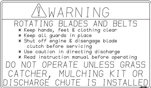
482286

482291
START/DRIVE PROCEDURE
- Engage parking brake
° Disengage mower deck drive
° Move control handles
to neutral lock position
e Start engine - Start engine a Release, ranking, brake
- Release parking brake
• Select forward or reverse with
hyrdo control handles

WARNING


AVOID SERIOUS INJURY OR DEATH
• Read the Operator's Manual
○ Operate only on slopes you can back up
• If machine stops going uphill.
stop blades and back down slowly
a Avoid sudden turns
• Avoid sudden turns
• Do not mow when children or others are ground
° Never carry children even with blades off
°Look down and behind before and while backing
- Keep safety devices (guards, shields, switches, etc.) in place and working
°Remove objects that could be thrown by the blades
° Trained operators only 483023
IMPORTANT
Operation on slopes
can be hazardous.
See your Scag
dealer for
available Roll-Over
Protective Systems
482834
482834
WARNING
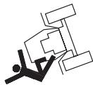
SERIOUS INJURY
OR DEATH MAY
RESULT FROM
RESULT FROM MACHINE ROLLOVER
HACHINE ROEES
Failure to follow these instructions could result
instructions could result in serious injury or death
Do not operate machine on
Do not operate machine on steep slopes or near drop offs
Avoid shape and/or quick turn
Avota sharp and/or quick
Do not exceed the machine weight rating of the BOPS
Algun use seat belt
Always use seat belt
Do not Jump if machine tips
If ROPS Is foldable:
Always keep ROPS fully extended with ROPS JUST BE PULL
WHEN ROPS MUST BE DOWN.
Do not use the seat belt
Do not use the seat belt
Drive with extra care
If equipped with seat platform:
Do not operate machine without
seat platform pin in place 28630450

481039

481568

482290
IMPORTANT ADJUSTMENT PROCEDURES
READ OPERATOR'S MANUAL FOR MORE DETAILS
Check tire pressure - (Drive tires-12 psi)
(Caster tires-25 psi)
NEUTRAL ADJUSTMENT

Rotate turnbuckle △
With an operator in the seat, engine running, control
lever in neutral and the parking brake disengaged
adjust control linkage. Loosen jam nuts. If wheel
rotates forward, adjust turnbuckle CW. If wheel
rotates rearward, adjust turnbuckle CCW. Adjust until
drive wheel stops turning. Tighten jam nuts. Repeat
procedure until proper Neutral Adjustment is obtained.
TRACKING ADJUSTMENT
If the machine pulls to the right, adjust LH control
linkage CW to slow left wheel. If the machine pulls to
the left adjust RH control linkage CW to slow right wheel. Readjust neutral if necessary.
To move machine without running the engine, rotate
both dump valves located at the LH side of the pumps
CCW 1/2 turn to "freewheel" positions. Return dump
valves to original position to operate the mower.
Tighten to 7-10 ft-lbs.
HYDRAULIC FLUID LEVEL
Check hydraulic fluid level
while fluid is cool. Fluid
level should be 3" below top
of filler neck. Fill with
SAE 20W50 motor oil only.
IMPORTANT
Do not overfill. Room
for hot fluid expansion
must be allowed or {
resulting expansion may
cause leaks in the
system.
482709
482709
483023
SPECIFICATIONS
3.1 ENGINE
General Type .... Heavy Duty Industrial/Commercial Gasoline
Brand ....Kohler
Horsepower 27 hp (Spec. #) ( Scag Model STWC61A-27CV)
25 hp (Spec. #FH721V) (Scag Model STWC52A-25KA)
Type 4 Cycle Gasoline, Twin Cylinder, Horizontal Shaft
Cylinders 2 with Cast Iron Sleeves
Governor .... Mechanical Type with Variable Speed Control Set At 3600 RPM
Idle Speed 1900 RPM
Fuel Pump Group .... Mechanical Fuel Pump with In-Line Fuel Filter
Fuel Non-Leaded Gasoline with a Minimum Octane Rating of 87
Oil Pump Group ...... Positive Displacement Gerotor™ Oil Pump
Starter.... Electric Starting with Solenoid Shift Starter
Belts: Kevlar cord. Self-adjusting, Self-tightening
Pump Drive Belt Scag Part Number - 482716
3.2 ELECTRICAL
Battery 12 Volt
Charging System ...... Alternator
Charging Output 12 Volt, 15 Amp
System Polarity ...... Negative Ground
Starter 12 Volt Electric Ring Gear Type, Key and Solenoid Operated Interlock
Switches....Seat, Neutral Control, Mower Engagement (BBC), Parking Brake
Instrument Panel ...... Key Switch, Throttle Lever, Manual Choke,
PTO Switch, Fuses and Safety Start module
Fuses Two (2) 20 Amp
3.3 TRACTOR
Drive System ...... Hydraulic Drive with Two Variable Displacement Pumps and Two Cast-iron High Torque Motors
Hydrostatic Pumps .... Two Hydro-Gear™ BDP 10A Pumps with Dump Valves for movement without running the engine
Drive Wheel Motors .... Two Parker Cast-Iron High Torque Motors
Steering/Travel Control.... Twin Lever Fingertip Steering Control with Individual Control to Each Wheel with Gas Spring Dampers
Parking Brake .... Lever Actuated Linkage to Brakes on Both Drive Wheel Axles
Wheels:
(2) Front Caster 13 X 6 Four-Ply w/tapered roller bearing pivots
(2) Drive 23 X 9.50 X 12 (52") Four-Ply Pneumatic Tubeless, Radius Edge
24 X 12 X 12 (61") Four-Ply Pneumatic Tubeless, Radius Edge
Fuel Tanks .... Dual 4.5-Gallon Seamless Polyethylene Tanks with large opening, Fuel Cap and molded cup holder in the right side fuel tank
Tire Pressure:
Front Caster 25 PSI
Drive 12 PSI
Seat ...... Padded, Thick Cushion with Extra Spring Support
3.3 TRACTOR (CONT'D)
-NOTE-
Travel Speed:
Forward 0-10 MPH
Reverse 0-5 MPH
The machine will travel at 10 mph for transport purposes. For best cutting performance the forward travel speed should be adjusted depending upon the cutting conditions.
3.4 CUTTER DECK
| Type: | Floating, Adjustable, Anti-scalping, Hybrid Design Combines Out-front and Belly-mount Designs |
| Construction: | Tri-plate deck construction, top of deck consists of three steel plates totaling nearly 1/2" of steel.,7-gauge (3/16") deck skirt. |
| True Cutting Width: | 52"(132.0cm),61"(155.0cm) |
| Cutting Height Adjustment: | Foot Operated Lever Adjustment from Operator's Seat, 1.00" to 5.5" in 1/4" increments |
| Cutter Blades: | .197 Thick, Milled Edge, Wear Resistant MarbainTM |
| Blade Engagement: | Electric Blade Engagement Clutch with Control Panel Switch Connected to the Cutter Deck through a Belt. |
| Discharge Opening: | Extra Wide Discharge Opening with Spring Loaded Discharge Chute and Turbo Baffle |
| Spindles: | Heavy-duty 1-1/8" Top Dimension Spindle Shaft, Cast Housing, Taper Roller Bearing, Low Maintenance with Top Access Grease Fitting and Grease Overfill Relief Poppet |
| Spindle Pulleys: | Split Steel with Easily Removed Taper Hubs |
| Cutter Deck Belts: | B-section with Kevlar Cord. Self-adjusting, Self-tightening |
| SMWC52 | Scag Part Numbers -482530 |
| SMWC61 | Scag Part Numbers -482652 |
| Electric Clutch Type | Ogura Heavy Duty PTO Clutch Brake |
3.6 HYDRAULIC SYSTEM
Hydraulic Oil Filter 10 Micron Spin-on Element Type
Hydraulic Reservoir ....Nylon; 2-1/2 Quart Capacity
3.7 PRODUCTIVITY
The following chart will aid you in determining how many acres your Scag mower will cut per day.
The chart is an estimate based on 8 hours per day cutting time at 7 MPH with a 20% allowance for overlap and turns.
Cutting Width: 52" 61"
Acres Per Day: 23 27
OPERATING INSTRUCTIONS

CAUTION:
Do not attempt to operate this mower unless you have read this manual. Learn the location and purpose of all controls and instruments before you operate this mower.
4.1 CONTROLS AND INSTRUMENT IDENTIFICATION
Before operating the mower, familiarize yourself with all mower and engine controls. Knowing the location, function and operation of these controls is important for safe and efficient operation of the mower.
- Ignition Switch (Figure 4-1). Used to start the engine and has three positions; OFF, ON, and START.
- Mower Deck Switch (Figure 4-1). Used to engage and disengage the mower drive system. Pulling up on the switch will engage the deck drive. Pushing down on the switch will disengage the deck drive.
- Engine Choke Control (Figure 4-1). Used to start a cold engine.
- Engine Throttle Control (Figure 4-1). Used to control the engine speed. Pushing the lever forward increases engine speed. Pulling the lever back decreases engine speed. Full backward position is the IDLE position. Full forward is the cutting position.

Figure 4-1 Controls and Instruments
- Hourmeter (Figure 4-1). Indicates the number of hours the engine has been operated. It operates whenever the ignition key switch is in the ON position. It can be used to keep track of maintenance intervals and the amount of time required to perform various tasks.
- Fuse Holders (Figure 4-1). Two 20-amp fuses protect the mower's electrical system. To replace fuses, pull fuse out of the socket and install a new fuse.
- Left Steering Control (Figure 4-1). Used to control the mower's left wheel when traveling forward or reverse.
- Right Steering Control (Figure 4-1). Used to control the mower's right wheel when traveling forward or reverse.
- Parking Brake Control (Figure 4-1). Used to engage and disengage the parking brakes. Pull the lever back to engage the parking brakes. Push the lever forward to disengage the parking brakes.
- Fuel Switching Valve (Figure 4-1). Located on the left side of the machine. Used to shut off fuel supply to the engine and change fuel supply between the fuel tanks. Rotate the valve counter-clockwise to supply fuel from the tank on the left side only. Rotate the valve clockwise to supply fuel from the tank on the right side only.
- Dump Valve Control Levers (Figure 4-2). Located on the hydraulic pumps, used to “free-wheel” the mower. Rotating the levers clockwise until they stop allows the unit to move under hydraulic power. The levers must be in this position and torqued to 10ft/lbs during operation of the mower. Rotating the levers counter-clockwise, 1-2 turns, allows the mower to be moved by hand (free-wheeling).
- Deck Lift Foot Lever (Figure 4-1). Used to raise and lower the cutter deck.
- Cutting Height Adjustment (Figure 4-1). Used to set the cutter deck at the desired cutting height.
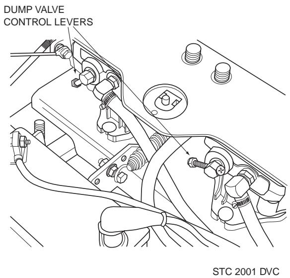
Figure 4-2 Dump Valve Control
- Deck Release Lever (Figure 4-1). Used to lock the cutter deck in the transport position. Push the foot pedal forward and lift up on the release lever to release the cutter deck for normal mowing.
- Seat Belt (Figure 4-1). Used to secure the operator. Seat belt must be worn at all times during operation
4.2 SAFETY INTERLOCK SYSTEM
The mower is equipped with a safety interlock system that prevents the engine from starting unless the deck drive is disengaged, the parking brake is engaged, the steering control levers are in the neutral position and the operator is in the seat. The interlock system shuts off the engine if the operator leaves the seat with the steering control levers not in the neutral position and/or the cutter blades engaged and/or the parking brake not engaged.

Never operate the mower with the interlock system disconnected or malfunctioning. Do not disengage or bypass any switch; injury to yourself and others or property damage could result.
4.3 INITIAL RUN-IN PROCEDURES (First Day of Use or Approximately 10 Hours)
- Check all belts for proper alignment and wear at 2, 4 and 8 hours.
- Change the engine oil and oil filter after the first 8 hours of operation. (See Section 7.4.)
- Check hydraulic oil level in reservoir. (See Section 7.3)
- Check for loose hardware. Tighten as needed.
- Check interlock system for proper operation. (See Section 4.2)
- Check tire pressure. Adjust pressure if necessary. (See Section 7.10)
4.4 STARTING THE ENGINE
CAUTION:
DO NOT USE STARTING FLUIDS. Use of starting fluids in the air intake system may be potentially explosive or cause a “runaway” engine condition that could result in engine damage and/or personal injury.
- Be sure the fuel shutoff valve, located behind the operator's seat by the left fuel tank, is completely open. (See Section 7.5)
- Sit in the operator's seat, fasten seat belt and place the steering control levers in the neutral position.
- Engage the parking brake.
- If the engine is cold, choke the engine as needed.
-
Move the engine throttle control to about half engine speed.
-
Turn the ignition key to the START position and release the key as soon as the engine starts. Do not hold the key in the START position for more than 15 seconds at a time. Allow at least 60 seconds between each cranking attempt to prevent overheating of the starter motor. Prolonged cranking can damage the starter motor and shorten battery life.
-
Allow engine to warm before operating the mower.
4.5 GROUND TRAVEL AND STEERING
-IMPORTANT-
If you are not familiar with the operation of a machine with lever steering and/or hydrostatic transmissions, the steering and ground speed operations should be learned and practiced in an open area, away from buildings, fences, or obstructions. Practice until you are comfortable with the handling of the machine before attempting to mow. Learn the operation on flat ground before operating on slopes.
-IMPORTANT-
Start practicing with a slow engine speed and slow forward travel. Learn to feather the steering controls to obtain a smooth operating action.
Forward Travel
To travel forward with the mower, disengage the parking brake, pull levers inward out of the neutral lock position and slowly push the steering control levers forward an equal distance. The further the steering control levers are pushed forward the greater the forward speed will be. To increase the speed, push the steering control levers further forward and to decrease the speed, pull the steering control levers back.
To stop the forward travel, pull the steering control levers back to the neutral position.
To steer the mower left while traveling forward, pull the left steering lever back. The further the lever is pulled back, the quicker the mower will turn left.
To steer the mower right while traveling forward, pull the right steering control lever back. The further the lever is pulled back, the quicker the mower will turn right.
-NOTE-
Smooth operation of the steering levers will produce smooth mower operation. While learning the operation of the steering controls, keep the travel speed low.
-IMPORTANT-
Do not travel forward over a curb. The mower may hang up on the curb. Raise the deck and travel backwards over the curb at a 45 degree angle. (see section 4.1, item 13 for cutter deck raising instructions)
Reverse Travel

CAUTION:
Disengage power to the mower before backing up. Do not mow in reverse unless absolutely necessary and then only after observation of the entire area behind the mower.

CAUTION:
Before backing up, observe the rear for persons and obstructions. Clear the area before backing up. Possible injury or property damage could occur.
To travel in reverse, pull levers inward out of the neutral lock position and pull both handles back. Keep the travel speed low while traveling in reverse.
-NOTE-
The mower may not travel straight in reverse. Slight adjustments must be made using the steering controls.
To steer left while traveling in reverse, allow the left steering control lever to move forward. The further the control is allowed to move forward, the quicker the mower will turn left.
To steer right while traveling in reverse, allow the right steering control lever to move forward. The further the control is allowed to move forward, the quicker the mower will turn right.
To stop the reverse travel, allow the steering control levers to return to the neutral position. If the mower is to be parked, place the handles in the neutral lock position and engage the parking brake.
4.6 ENGAGING THE DECK DRIVE (CUTTER BLADES)
- Set the throttle at about 3/4 speed. Do not attempt to engage the deck drive at high speed as this shortens the electric clutch life — use only moderate engine speed when engaging the deck drive.
- Engage the deck drive by pulling out on the yellow switch, located on the instrument panel, (Figure 4-3) to the engage position.
-NOTE-
A squealing noise may be heard when engaging or disengaging the deck drive. It is caused by the electric clutch plates meshing as the mower comes up to speed. This is normal.
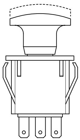

PULL UP TO ENGAGE
PUSH DOWN TO DISENGAGE
STT99CES
Figure 4-3 Cutter Engage Switch
- To disengage the deck drive, push the switch in to the disengage position.
- Always operate the engine at full throttle to properly maintain cutting speed. If the engine starts to lug down, reduce the forward speed and allow the engine to operate at maximum RPM.
DO NOT operate on steep slopes. To check a slope, attempt to back up it (with the cutter deck down). If the machine can back up the slope without the wheels slipping, reduce speed and use extreme caution. ALWAYS FOLLOW OSHA APPROVED OPERATION.
- This mower has been designed for good traction and stability under normal mowing conditions. However, caution must be used when traveling on slopes, especially when the grass is wet. Wet grass reduces traction and steering control. The Roll Over Protection System is standard equipment for this machine. See Section 2.5, page 7 of this manual for further details.
- To prevent tipping or loss of control, do not start or stop suddenly, avoid unnecessary turns and travel at reduced speed. If tires loose traction, disengage blades and proceed slowly off the slope.
- Avoid sudden starts when mowing uphill. Sudden starts may cause the machine to tip backwards.
- Loss of traction may occur when traveling down hill. Weight transfers to the front of the machine and may cause the drive wheels to slip causing loss of braking or steering.
- Keep tires properly inflated.
4.8 PARKING THE MOWER
- Park the machine on a flat, level surface only. Do not
park the machine on an incline.
- Place the steering control levers in the neutral position.
- Disengage the cutter blades.
- Slow the engine to idle speed.
- Engage the parking brake.
- Turn the ignition key to the OFF position and remove the key.
4.9 AFTER OPERATION
- Wash the entire mower after each use. Do not use high pressure spray or direct the spray onto electrical components.
-IMPORTANT-
Do not wash a hot or running engine. Cold water will damage the engine. Use compressed air to clean the engine if it is hot.
- Keep the entire mower clean to inhibit serious heat damage to the engine or hydraulic oil circuit.
- Check the drive belts for proper alignment and any signs of wear. Correct and adjust if necessary.

DANGER:
To avoid injury from burns, allow the mower to cool before removing the fuel tank cap and refueling.
- After the mower has cooled down, fill the fuel tanks with fresh, clean fuel at the end of every day of operation. See Engine Owner's Manual for proper octane requirements.
- Check the tire pressure. Adjust pressure if necessary.
4.10 REMOVING CLOGGED MATERIAL

DANGER:
ROTATING BLADES
NEVER PUT YOUR HANDS INTO THE DISCHARGE CHUTE FOR ANY REASON! Shut off the engine and remove the key and only then use a stick or similar object to remove material if clogging has occurred.
- If the discharge chute becomes clogged, shut off the engine and remove the ignition key. Using a stick or similar item, dislodge the clogged material. Then resume normal mowing.
4.11 MOVING MOWER WITH ENGINE STOPPED
To “free-wheel” or move the mower around without the engine running, place the dump valve levers in the FREE-WHEEL position (Figure 4-2, page 13). Disengage the parking brake and move the mower by hand. The dump valve levers must be returned to the DRIVE position and torqued to 7-10 ft/lbs to drive the mower.
4.12 RECOMMENDATIONS FOR MOWING
- Do not mow with dull blades. A dull blade will tear grass, resulting in poor lawn appearance and require extra power.
- The discharge chute must not be removed and must be kept in the lowest position to deflect grass clippings and thrown objects downward. Direct the side discharge away from sidewalks or streets to minimize cleanup of clippings. When mowing close to obstacles, direct the discharge away from the obstacles to reduce the chance of property damage by thrown objects.

WARNING
DO NOT OPERATE WITHOUT DISCHARGE CHUTE, MULCHING KIT, OR ENTIRE GRASS CATCHER INSTALLED
-
Cut grass when it is dry and not too tall. Do not cut grass too short (cut off 1/3 or less of existing grass for best appearance). Mow frequently.
-
Keep mower and discharge chute clean.
- When mowing wet or tall grass, mow the grass twice. Raise the mower to the highest setting for the first pass and then make a second pass to the desired height.
- Use a slow travel speed for trimming purposes.
- Operate the engine at full throttle for best cutting. Mowing with a lower RPM causes the mower to tear the grass. The engine is designed to be operated at full speed.
- Use the alternate stripe pattern for best lawn appearance. Vary the direction of the stripe each time the grass is mowed to avoid wear patterns in the grass.
4.13 ADJUSTING CUTTING HEIGHT
The mower deck can be adjusted from a height of 1-inch to 5-1/2 inches at 1/4-inch intervals. To adjust the cutting height:

WARNING:
DO NOT adjust the cutting height with the mower blades rotating. Disengage the power to the cutter blades and then adjust cutting height.
- Disengage the power to the cutter blades.
- Push the cutting height adjustment foot pedal all the way forward using your right foot until it locks in place. (Figure 4-5, page 18)
- Insert the lanyard pin into the cutting height index at the desired cutting height. Push forward on the deck lift foot lever, hold in place and lift up on the deck release lever, (Figure 4-4). Slowly release the foot pedal. A deck height decal is located on the cutting height index as an aid in adjusting the deck to the desired height. (Figure 4-5)

Figure 4-4 Deck Release Lever

Figure 4-5 Adjusting Cutting Height
4.14 TOWING (optional hitch accessory)
- Never allow children or others in or on towed equipment.
- Tow only with a machine that has a hitch designed for towing. Do not attach towed equipment except at the hitch point.
- Follow manufacturer's recommendations for weight limit for towed equipment. 250lbs. maximum towing weight.
- Never tow on slopes. The weight of the towed equipment may cause loss of traction and loss of control.
- Travel slowly and allow extra distance to stop.
- Zero turning with a trailer attached, could cause damage to the trailer or mower.
TROUBLESHOOTING CUTTING CONDITIONS
| CONDITION | CAUSE | CURE |
| Stringers - Occasional Blades of Uncut Grass | Low engine RPM | Run engine at full RPM |
| Ground speed too fast | Slow speed to adjust for conditions | |
 | Wet grass | Cut grass after it has dried out |
| Dull blades, incorrect sharpening | Sharpen blades | |
| Deck plugged, grass accumulation | Clean underside of deck | |
| Width of Deck SGB020 | Belts slipping | Adjust belt tension |
| Streaking - Strips of Uncut Grass in Cutting Path | Dull, worn blades | Sharpen blades |
| Incorrect blade sharpening | Sharpen blades | |
| Low engine RPM | Run engine at full RPM | |
 | Belt slipping | Adjust belt tension |
| Deck plugged, grass accumulation | Clean underside of deck | |
| Ground speed too fast | Slow speed to adjust for conditions | |
| Wet grass | Cut grass after it has dried out | |
| Width of Deck SGB018 | Bent blades | Replace blades |
| Streaking - Strips of Uncut Grass Between Cutting Paths | Not enough overlapping between rows | Increase the overlap of each pass |
 |
TROUBLESHOOTING (CONT'D)
| CONDITION | CAUSE | CURE |
| Uneven Cut on Flat Ground - Wavy High-Low Appearance, Scalloped Cut, or Rough Contour | Lift worn from blade | Replace blade |
| Blade upside down | Mount with cutting edge toward ground | |
| Deck plugged, grass accumulation | Clean underside of deck | |
| Too much blade angle (deck pitch) | Adjust pitch and level | |
 | Deck mounted improperly | See your authorized SCAG dealer |
| Bent spindle area | See your authorized SCAG dealer | |
| Dull blade | Sharpen blade | |
| Uneven Cut on Uneven Ground - Wavy Appearance, High-Low Scalloped Cut, or Rough Contour | Uneven ground | May need to reduce ground speed, raise cutting height, and/or change direction of cut |
 | ||
| Sloping Ridge Across Width of Cutting Path | Tire pressures not equal | Check and adjust tire pressure |
| Wheels uneven | Check and adjust tire pressure | |
 | Deck mounted incorrectly | See your authorized SCAG dealer |
| Deck not level side-to side | Check for level and correct | |
| Width of Deck SGB023 |
TROUBLESHOOTING (CONT'D)
| CONDITION | CAUSE | CURE |
| Scalping - Blades Hitting Dirt or Cutting Very Close to the Ground | Low tire pressures | Check and adjust pressures |
| Ground speed too fast | Slow speed to adjust for conditions | |
| Cutting too low | May need to reduce ground speed, raise cutting height, change direction of cut, and/or change pitch and level | |
 | Rough terrain | May need to reduce ground speed, raise cutting height, and/or change direction of cut |
| Ground speed too fast | Slow speed to adjust for conditions | |
| Wet grass | Cut grass after it has dried out | |
| Step Cut - Ridge in Center of Cutting path | Blades not mounted evenly | Adjust pitch and level |
| Bent blade | Replace blade | |
 | Internal spindle failure | See your authorized SCAG dealer |
| Mounting of spindle incorrect | See your authorized SCAG dealer | |
| Slope Cut - Sloping Ridges Across Width of Cutting Path | Bent spindle mounting area | See your authorized SCAG dealer |
| Internal spindle failure | See your authorized SCAG dealer | |
| Bent deck housing | See your authorized SCAG dealer | |
 |
ADJUSTMENTS
6.1 PARKING BRAKE ADJUSTMENT

WARNING:
Do not operate the mower if the parking brake is not operable. Possible severe injury could result.
The parking brake linkage should be adjusted whenever the parking brake lever is placed in the “ENGAGE” position and the parking brake will not prevent the mower from moving. If the following procedures do not allow you to engage the parking brake properly, contact your Scag dealer for further brake adjustments.
- Position a floor jack under the rear of the machine. Raise the machine and support it to prevent it from falling. Block the caster wheels to prevent the machine from moving. Remove the drive wheels.
- With the brake in the engaged position, check the distance between the lower nut on the brake actuator rod and the brake actuator lever on the LH side of the machine. The distance should be 1/8" (See Figure 6-2).
- If the distance is not at the specified measurement, loosen the jam nut at the clevis on the top of the brake actuator rod (See Figure 6-2).
- Turn the bolt at the bottom of the brake actuator lever until the 1/8" measurement is achieved and tighten the jam nut at the clevis on the brake actuator rod. (See Figure 6-2). If the 1/8" measurement can not be achieved by adjusting the brake actuator rod, adjust the brake control rod. Adjust by loosening the jam nuts at both ends of the brake control rod and turning the rod until the proper distance is achieved. (See Figure 6-1)
- Repeat steps 2-4 on the RH side of the machine.
- Replace the drive wheels and test the brake.
-NOTE-
If this procedure does not achieve proper brake adjustment, please contact your authorized Scag dealer.

Figure 6-1. Brake Adjustment

Figure 6-2. Brake Rod Adjustment
6.2 TRAVEL ADJUSTMENTS
Neutral or tracking adjustments will need to be made if:
A. The steering control levers are in the neutral position and the machine creeps forward or backward. (See Neutral Adjustment).
B. The steering control levers are in the full forward position and the mower pulls to one side or the other when traveling in a forward direction. (Tracking Adjustment, See Page 23).
Neutral Adjustment
-
Be sure the dump valve levers are in the run position and the steering control levers are in the neutral lock position.
-
With an operator in the seat, start the engine and disengage the parking brake.
-
Run the engine at full operating speed and check if the machine creeps forward or backwards.
-
Adjust the RH wheel by loosening the jam nuts on the steering control rod and turning the rod until the drive wheel turns in the forward direction. Turn the rod back until the drive wheel stops moving. Turn the rod back an additional 1/2 turn. (See Figure 6-3).
-
Tighten the jam nuts and repeat for the LH wheel.
-
Actuate the steering control levers forward and reverse several times and return them to the neutral position.
-
Check that the drive wheels remained in neutral and readjust if necessary.
-
Check that the steering control levers hit the stop before the pumps reach full stroke. Adjust as needed.
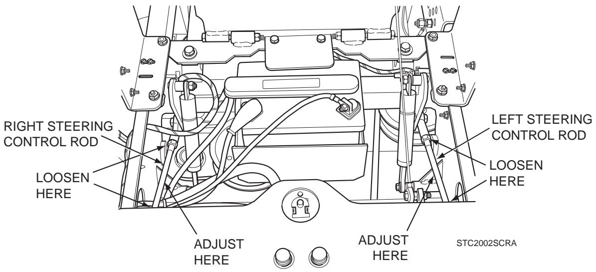
Figure 6-3. Steering Control Rods Adjustment
Tracking Adjustment

CAUTION:
Stop the engine and remove the key from the ignition before making any adjustments. Wait for all moving parts to come to a complete stop before beginning work.

CAUTION:
The engine and drive unit can get hot during operation causing burn injuries. Allow engine and drive components to cool before making any adjustments.
-NOTE-
Before proceeding with this adjustment, be sure that the caster wheels turn freely and that the tire pressure in the drive wheels is correct. If the tire pressure is not correct, the machine will pull to the side with the lower pressure.
- If at full speed the mower pulls right, it is an indication that the left wheel is turning faster than the right wheel. To adjust this condition, proceed as follows:
A. Stop the machine and place the steering control levers in the neutral position. Loosen the lock nuts securing the ball joints at each end of the LH steering control rod. Rotate the control rod to shorten the rod and tighten the lock nuts. This will cause the control rod to stroke the LH pump less, slowing down the LH wheel. (See Figure 6-3).
-NOTE-
If after making the adjustment as outlined in step 1A, the machine creeps forward or backward, the neutral adjustment must be made as described on page 23.
- If at full speed the mower pulls left, it is an indication that the right wheel is turning faster than the left wheel. To adjust this condition, proceed as follows:
A. Stop the machine and place the steering control levers in the neutral position. Loosen the lock nuts securing the ball joints at each end of the RH steering control rod. Rotate the control rod to shorten the rod and tighten the lock nuts. This will cause the control rod to stroke the RH pump less, slowing down the RH wheel. (See Figure 6-3).
-NOTE-
If after making the adjustment as outlined in step 2A, the machine creeps forward or backward, the neutral adjustment must be made as described on page 23.
6.3 THROTTLE CONTROL AND CHOKE ADJUSTMENTS
These adjustments must be performed by your Scag dealer to ensure proper and efficient running of the engine. Should either the throttle or choke controls need adjustment, contact your authorized Scag service center.
6.4 BELT ADJUSTMENT

WARNING:
Before removing any guards, shut the engine off and remove the ignition key.
All drive belts and cutter deck belts are spring loaded and self-tensioning. The belts should be checked periodically for proper alignment and wear.
6.5 BELT ALIGNMENT
Belt alignment is important for proper performance of your Scag mower. If you experience frequent belt wear or breakage, see your authorized Scag service center for belt adjustment.
6.6 CUTTER DECK ADJUSTMENTS
Cutter deck level, pitch and height are set at the factory. However, if these adjustments should ever need to be made, the following procedures will aid in obtaining the proper cutter deck adjustment.
-NOTE-
Before proceeding with the cutter deck adjustments, be sure that all tires are properly inflated.
Cutter Deck Level
The cutter deck should be level from side-to-side for proper cutting performance. To check for level, be sure that the mower is on a flat, level surface, the tires are properly inflated and the cutter deck is set at the most common cutting height that you will use. On the RH side of the machine, check the distance from the top of the cutter deck to the floor. Next check the distance from the top of the cutter deck to the floor on the LH side of the machine. Both measurements should be the same. If the two measurements are different, the cutter deck level must be adjusted as follows:
- On the front LH side of the cutter deck locate the cutter deck adjusting bolt. (See Figure 6-4)

Figure 6-4. Cutter Deck Adjustment
- Loosen the elastic stop nut and move the bolt up or down in the slot to adjust the cutter deck until the distance from the top of the cutter deck to the floor is the same as the measurement on the RH side of the machine.
- Tighten the elastic stop nut to secure the cutter deck in the proper position.
Cutter Deck Pitch
The pitch of the cutter deck should be equal between the front and rear of the cutter deck for proper cutting performance. To check for proper deck pitch, be sure that the mower is on a flat, level surface and the tires are properly inflated.
Check the distance from the top of the cutter deck to the floor at the rear RH side of the cutter deck directly behind the cutter deck hanging chains. Next check the distance from the top of the cutter deck to the floor at the front RH side of the cutter deck directly in front of the cutter deck hanging chains. The measurement at the front of the cutter deck should be the same as the rear of the deck. Make these measurements at the LH side of the cutter deck also. If the measurement at the front of the deck is not the same, the cutter deck pitch must be adjusted as follows:
- Loosen the lock nuts on both adjusting rods. (See Figure 6-4)
- Using an adjustable jaw pliers, turn the adjusting rods on the non-threaded portion of the rod until the deck is equal front to back on both the RH and the LH side of the cutter deck. Tighten both lock nuts.
-NOTE-
To prevent the cutter deck from teetering, all four cutter deck hanging chains must have tension on them. If all four chains do not have tension on them and the deck teeters, you must readjust the cutter deck as outlined in the procedures above. All measurements should be taken from the top edge of the deck as the Advantage decks have an uneven bottom edge.
Cutter Deck Height
The cutter deck height adjustment is made to ensure that the cutter deck is cutting at the height indicated on the cutting height index gauge. To check for proper deck height, be sure that the mower is on a flat, level surface and the tires are properly inflated.
- Place the cutter deck in the transport position. Loosen the jam nuts on both ends of the deck height control rod. (See Figure 6-5)

Figure 6-5. Cutter Deck Height Adjustment
- Turn the control rod (See Figure 6-6) until there is a 1/4" space between the rear deck stop and the top of the cutter deck. (See Figure 6-6). Tighten the jam nuts on the control rod.

Figure 6-6. Cutter Deck Stop
- Check the cutter deck cutting height by placing the lanyard pin in the 3" position on the cutting height index. Release the deck from the transport positon and allow the deck to move to the 3" cutting height position.
- Check the measurement from the floor to the cutter blade tip. If the measurement is not at 3", an adjustment can be made using the deck height control rod. (See Figure 6-5)
-NOTE-
If an adjustment had to be made, be sure that the cutter deck can easily be locked into the transport position.
Custom-Cut Baffle Adjustment
The Custom-Cut Baffle is designed to deliver optimum airflow and superior cutting performance in any type of grass. The Custom-Cut Baffle can be raised or lowered to precisely tailor the deck's performance for the type of grass being cut. The baffle can be set in three (3) different positions for optimum performance.
A. 3" Position - baffle is installed using the top set of holes on the front baffle welded inside the cutter deck. (See Figure 6.8). The Advantage cutter deck will deliver the best quality-of-cut in very tall, wiry, tough to cut grass.
B. 3-1/2" Position (factory setting) - baffle is installed using the middle set of holes on the front baffle welded inside the cutter deck. (See Figure 6.9). For general purpose cutting, place the Custom-Cut Baffle in the 3-1/2" position. This gives the best mix of cutting performance in all types of grass.
C. 4" Position - baffle is installed using the bottom set of holes on the front baffle welded inside the cutter deck. (See Figure 6.10). Placing the baffle in the 4" setting will enhance fall cutting (leaf pickup) and reduce cutter deck "blowout".
To adjust the Custom-Cut Baffle height:
- Place the cutter deck in the transport position.
- Remove the hardware securing the Custom-Cut Baffle to the cutter deck. (See Figure 6.7).
-NOTE-
Hardware location used in the illustrations are for reference only. Location of hardware may vary depending on cutter deck size.

Figure 6-7. Custom-Cut Baffle
-
Move the Custom-Cut Baffle to desired position. (See Figures 6.9 through 6.11 for position).
-
Reinstall the mounting hardware as shown. (See Figures 6.10 though 6.11). Torque hardware to 39ft-lbs.

Figure 6-8. 3" Custom-Cut Baffle Position

Figure 6-9. 3-1/2" Custom-Cut Baffle Position

Figure 6-10. 4" Custom-Cut Baffle Position
MAINTENANCE
7.1 MAINTENANCE CHART - RECOMMENDED SERVICE INTERVALS
| HOURS | Procedure | Comments | |||||
| Break-In(First 10) | 8 | 40 | 100 | 200 | 500 | ||
| X | Check all hardware for tightness | ||||||
| X | Check hydraulic oil level | See paragraph 7.3 | |||||
| X | Check all belts for proper alignment | See paragraph 7.8 | |||||
| X(First 8) | Change engine oil and filter | See paragraph 7.4 | |||||
| X | Check hydraulic hoses for leaks | Use extreme caution when checking the hydraulic hoses See paragraph 2.5 | |||||
| X | Check engine oil level | See paragraph 7.4 | |||||
| X | *Clean mower | See paragraph 7.11 | |||||
| X | Check condition of blades | See paragraph 7.9 | |||||
| X | Apply grease to fittings | See paragraph 7.2 | |||||
| X | Check tire pressure | See paragraph 7.10 | |||||
| X | Check battery electrolyte level, clean battery posts and cables | See paragraph 7.7 | |||||
| X | Check belts for proper alignment | See paragraph 7.8 | |||||
| X | Apply grease to fittings | See paragraph 7.2 | |||||
| X | Change engine oil | See paragraph 7.4 | |||||
| X | *Clean air cleaner element | See paragraph 7.6 | |||||
* Perform these maintenance procedures more frequently under extreme dusty or dirty conditions.
MAINTENANCE CHART - RECOMMENDED SERVICE INTERVALS (CONT'D)
| HOURS | Procedure | Comments | |||||
| Break-In(First 10) | 8 | 40 | 100 | 200 | 500 | ||
| X | Apply grease to fittings | See paragraph 7.2 | |||||
| X | Check hardware for tightness | ||||||
| X | Change engine oil filter | See paragraph 7.4 | |||||
| X | Check hydraulic oil level | See paragraph 7.3 | |||||
| X | Replace engine fuel filter | See paragraph 7.5 | |||||
| X | Drain hydraulic system and replace hydraulic oil | See paragraph 7.3Use SAE 20W50Motor Oil | |||||
| X | Replace hydraulic oil filter | See paragraph 7.3 | |||||
| X | Adjust electric PTO clutch | See Scag Dealer | |||||
7.2 LUBRICATION - GREASE FITTING LUBRICATION CHART (SEE FIGURE 7-1)
| LOCATION | LUBRICATION | NO. OF PLACES | ||
| INTERVAL | LUBRICANT | |||
| 1 | Caster Wheel Pivot * | 500 Hours/Yearly | Chassis Grease | 2 |
| 2 | Caster Wheel Bearings | 100 Hours/Bi-Weekly | Chassis Grease | 2 |
| 3 | Brake Actuator | 200 Hours/Monthly | Chassis Grease | 2 |
| 4 | Cutter Deck Bellcranks | 100 Hours/Bi-Weekly | Chassis Grease | 4 |
| 5 | Cutter Deck Pusharms | 100 Hours/Bi-Weekly | Chassis Grease | 2 |
| 6 | Control Pivot | 100 Hours/Bi-Weekly | Chassis Grease | 2 |
| 7 | Cutter Deck Spindle | 40 Hours/Weekly | +Lithium MP White Grease 2125 | 3 |
| 8 | Brake Handle | 200 Hours/Monthly | Chassis Grease | 1 |
* PROCEDURE: Remove grease cap, part number 481559. Remove plug, part number 482028-01, and install grease zerk. Apply grease to the fitting until new grease appears at the top of the caster extension. Remove the grease zerk and reinstall the plug. Reinstall the grease cap. Special tool, part number 47007, is recommended for use in the installation of the grease cap.
+ Compatible Greases: Mobilix #2 found at Mobil Service Stations
Ronex MP found at Exxon Service Stations
Super Lube MEP #2 & Super Stay-M #2 found at Conoco Stations
Shell Alvania #2 found at Shell Service Stations
Lidok EP #2 found at industrial shops

Figure 7.1 Lubrication Fitting Points
7.3 HYDRAULIC SYSTEM
A. Checking Hydraulic Oil Level
The hydraulic oil level should be checked after the first 10 hours of operation. Thereafter, check the oil after every 200 hours of machine operation or monthly, whichever occurs first.
-IMPORTANT-
If the oil level is consistently low, check for leaks and correct immediately.
- Wipe dirt and contaminants from around the reservoir cap. Remove the cap from the hydraulic oil reservoir.
- Visually check the level of hydraulic oil. Hydraulic oil must be at least 3" inches from top of the filler neck. If the level cannot be determined visually, use a clean tape measure to check the level. If the fluid is low, add 20W50 motor oil. DO NOT overfill; (overfilling the oil reservoir may cause oil seepage).
- Clean the fill cap and install it onto the reservoir.
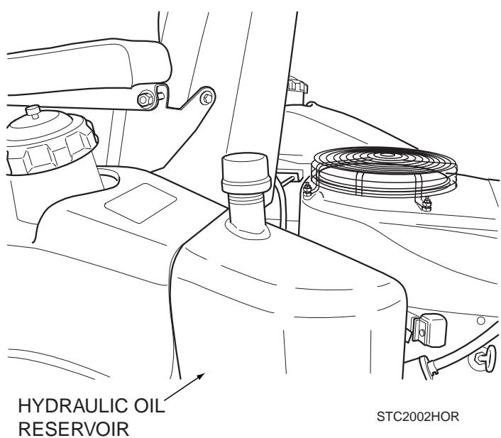
Figure 7-2 Hydraulic Oil Reservoir
B. Changing Hydraulic Oil
The hydraulic oil should be changed after every 500 hours or annually, whichever occurs first. The oil should also be changed if the color of the fluid has become black or milky. A black color and/or a rancid odor usually indicates possible overheating of the oil, and a milky color usually indicates water in the hydraulic oil.
-IMPORTANT-
The hydraulic oil should be changed if you notice the presence of water or a rancid odor to the hydraulic oil.
- Park the mower on a level surface and stop the engine.
- Place a suitable container under the hydraulic oil filter. Tilt the seat forward. Remove the fill cap from the reservoir and the drain plug from the bottom of the drain tee fitting on the front side of the filter base. (See Figure 7-3). Allow the fluid to drain into the container and properly discard it.

Figure 7-3 Hydraulic Oil Filter and Drain Plug
- Re-install the drain plug into the tee fitting and be sure it is tight.
-NOTE-
Before refilling the hydraulic oil reservoir the hydraulic oil filter should be changed as outlined in section C -Changing Hydraulic Oil Filter Element- on the next page.
- Fill the reservoir to 3-1/4" inches from the top of the filler neck with SAE 20W50 motor oil.
- Replace the reservoir fill cap. Start the engine and drive forward and backward for two minutes. Check the oil level in the reservoir. If necessary, add oil to the reservoir.
C. Changing Hydraulic Oil Filter Element
The hydraulic oil filter should be changed after every 500 hours of operation or annually, whichever occurs first.
- Remove the oil filter element (Figure 7-3, Page 31) and properly discard it. Fill the new filter with clean SAE 20W50 engine oil and install the filter. Hand tighten only.
- Run the engine at idle speed with the speed control lever in neutral for five minutes.
- Check the oil level in the hydraulic tank. It must be 3-1/4" inches from the top of the filler neck. If necessary, add SAE 20W50 motor oil.
7.4 ENGINE OIL
A. Checking Engine Crankcase Oil Level
The engine oil level should be checked after every 8 hours of operation or daily as instructed in the Engine Operator's Manual furnished with this mower.
B. Changing Engine Crankcase Oil
After the first 5 hours of operation, change the engine crankcase oil and replace the oil filter. Thereafter, change the engine crankcase oil after every 100 hours of operation or bi-weekly, whichever occurs first. Refer to the Engine Operator's Manual furnished with this mower for instructions.

Figure 7-5 Kohler & Kawasaki Engine Oil Fill/Dipstick, Filter and Drain Plug Locations
C. Changing Engine Oil Filter
After the first 5 hours of operation, replace the engine oil filter. Thereafter, replace the oil filter after every 200 hours of operation or every month, whichever occurs first. Refer to Engine Operator's Manual for instructions.
7.5 ENGINE FUEL SYSTEM
DANGER:
To avoid injury from burns, allow the mower to cool before removing the fuel tank cap and refueling.
A. Filling the Fuel Tank
Fill the fuel tank at the beginning of each operating day to within 1 inch below the filler neck. Do not overfill. Use clean, fresh unleaded gasoline with a minimum octane rating of 87.
To avoid personal injury or property damage, use extreme care in handling gasoline. Gasoline is extremely flammable and the vapors are explosive.
-
Extinguish all cigarettes, cigars, pipes and other sources of ignition.
-
Use only an approved gasoline container.
-
Never remove the gas cap or add fuel with the engine running. Allow the engine to cool before fueling.
- Never fuel the machine indoors or in an enclosed trailer.
- Never store the machine or fuel container where there is an open flame, spark or pilot light such as on a water heater or other appliances.
- Never fill containers inside a vehicle or on a truck or trailer bed with a plastic liner. Always place containers on the ground away from your vehicle before filling.
- Remove the machine from the truck or trailer and fuel on the ground. If this is not possible, then refuel the machine with a portable container, rather than from a gasoline dispenser nozzle.
- Keep the nozzle in contact with the rim of fuel tank or container opening at all times until fueling is complete. Do not use a nozzle lock-open device.
- If fuel is spilled on clothing, change clothing immediately and wash affected skin.
- Replace gas cap and tighten securely.

Figure 7-6 Engine Fuel Filter Location
7.6 ENGINE AIR CLEANER
A. Cleaning and/or Replacing Air Cleaner Element
For any air cleaner, the operating environment dictates the air cleaner service periods. Inspect and clean the air cleaner element after every 100 hours of operation or bi-weekly, whichever occurs first and replace the element if required.
-NOTE-
In extremely dusty conditions it may be necessary to check the element once or twice daily to prevent engine damage.
- Release the two latches securing the air cleaner cover to the air cleaner assembly and remove the cover. Set aside.
2 Remove the air cleaner and inspect. - Clean or replace the air cleaner and foam pre-cleaner as recommended by the engine manufacturer.
7.7 BATTERY

WARNING:
Battery posts, terminals, and related accessories contain lead and lead compounds, chemicals known to the State of California to cause cancer and reproductive harm. Wash hands after handling.

WARNING:
Lead-acid batteries produce flammable and explosive gases. To avoid personal injury when checking, testing or charging batteries, DO NOT use smoking materials near batteries. Keep arcs, sparks and flames away from batteries. Provide proper ventilation and wear safety glasses.
WARNING:
Electric storage battery fluid contains sulfuric acid which is POISON and can cause SEVERE CHEMICAL BURNS. Avoid contact of fluid with eyes, skin, or clothing. Use proper protective gear when handling batteries. DO NOT tip any battery beyond 45° angle in any direction. If fluid contact does occur, follow first aid suggestions below.
BATTERY ELECTROLYTE FIRST AID
EXTERNAL CONTACT — Flush with water.
EYES — Flush with water for at least 15 minutes and get medical attention immediately.
INTERNAL — Drink large quantities of water. Follow with Milk Of Magnesia, beaten egg, or vegetable oil. Get medical attention immediately. In case of internal contact, DO NOT give fluids that would induce vomiting.
A. Charging the Battery
Refer to the battery charger's manual for specific instructions.
Under normal conditions the engine's alternator will have no problem keeping a charge on the battery. If the battery has been completely discharged for a long period of time, the alternator may not be able to recharge the battery, and a battery charger will be required.
DO NOT charge a frozen battery. It may explode and cause injury. Let the battery warm before attaching a charger.
Whenever possible, remove the battery from the mower before charging and make sure the electrolyte covers the plates in all cells.
WARNING:
BATTERIES PRODUCE EXPLOSIVE GASES. Charge the battery in a well ventilated space so gases produced while charging can dissipate.
Charging rates between 3 and 50 amperes are satisfactory if excessive gassing or spewing of electrolyte does not occur or the battery does not feel excessively hot (over 125° F). If spewing or gassing occurs or the temperature exceeds 125° F, the charging rate must be reduced or temporarily stopped to permit cooling.
B. Jump Starting
- The booster battery must be a 12 volt type. If a vehicle is used for jump starting, it must have a negative ground system.
- When connecting the jumper cables, connect the positive cable to the positive battery post, then connect the negative cable to the negative battery post.
7.8 DRIVE BELTS
All drive belts are spring loaded and self-tensioning, however after the first 2, 4, 8 and 10 hours of operation, the belts should be checked for proper alignment and wear. Thereafter, check the belts after every 40 hours of operation or weekly, whichever occurs first.
-NOTE-
If you experience frequent belt wear or breakage, see your authorized Scag Dealer for belt adjustment.
7.9 CUTTER BLADES
A. Blade Inspection
- Remove the ignition key before servicing the blades.
- Raise the mower deck to the highest position. Place the lanyard pin in the highest cutting height positon to prevent the cutter deck from falling.
WARNING:
Always wear proper hand and eye protection when working with cutter blades.
- Check the cutter blades for straightness. If the cutter blades appear bent, they will need to be replaced.
WARNING:
Do not attempt to straighten a bent blade, and never weld a broken or cracked blade. Always replace it with a new blade to assure safety.
- If a blade cutting edge is dull or nicked, it should be sharpened. Remove the blades for sharpening. See "Blade Replacement."
-NOTE-
Keep the blades sharp. Cutting with dull blades not only yields a poor mowing job, but slows the cutting speed of the mower and causes extra wear on the engine and the blade drive.
B. Blade Sharpening
-NOTE-
If possible, use a file to sharpen the blade. Using a wheel grinder may burn the blade.
-NOTE-
DO NOT sharpen the blades beyond 1/3 of the width of the blade.
- Sharpen the cutting edge at the same bevel as the original (See Figure 7-9). Sharpen only the top of the cutting edge to maintain sharpness.

Figure 7-9 Blade Sharpening
- Check the balance of the blade. If the blades are out of balance, vibration and premature wear can occur. See your authorized Scag dealer for blade balancing or special tools, if you choose to balance your own blades.
C. Blade Replacement
WARNING:
Always wear proper hand and eye protection when working with cutter blades.
- Remove the ignition key before replacing the blades.
-
Raise the mower deck to the highest position. Place the lanyard pin in the highest cutting height positon to prevent the cutter deck from falling.
-
Secure the cutter blades to prevent them from rotating, (Use the optional Blade Buddy tool, P/N 9212, to assist in securing the cutter blades), remove the nut from the blade attaching bolt. Remove the cutter blade, bolt and spacer from the spindle shaft. (Figure 7-10).
-NOTE-
The front of the machine will have to be raised slightly to remove the blade bolt from the cutter spindle.
- To install the new cutter blade, put the flat washer onto the blade bolt and slide the bolt into the hole in the cutter blade.

Figure 7-10 Blade Replacement
-NOTE-
Be sure that the blade is installed with the lift wing toward the top.
- Install the spacer onto the blade bolt and insert the bolt into the cutter spindle shaft.
- Install the hex nut to the blade bolt at the top of the cutter spindle. Secure the blades from rotating and torque to 75 ft-lbs. (See Figure 7-10)
7.10 TIRES
Check the tire pressures after every 8 hours of operation or daily.
Caster Wheels 25 PSI
Drive Wheels 12 PSI
7.11 BODY, DECK, AND UPHOLSTERY

CAUTION:
Do not wash any portion of the equipment while it is hot. Do not wash the engine; use compressed air.
- After each use, wash the mower and cutter deck. Use cold water and automotive cleaners. Do not use pressure cleaners.
- Do not spray electrical components.
- Use a mild soap solution or a vinyl/rubber cleaner to clean the seat.
- Repair damaged metal surfaces using Scag touch-up paint (P/N 48521) available from your authorized Scag dealer. Wax the mower with an automotive paint wax for maximum paint protection.
NOTES
52A" CUTTER DECK

52A" CUTTER DECK
| Ref. No. | Part No. | Description | Ref. No. | Part No. | Description |
| 1 | 461651 | Cutter Deck Advantage | 37 | 481022 | Bearing Assembly |
| 2 | 43063 | Spacer | 38 | 48114-04 | Grease Fitting |
| 3 | 04019-04 | Nut, 3/8-16 Serrated Flange | 39 | 48677 | Valve, Grease Relief |
| 4 | 481625-01 | Wing Nut, 3/8-16 | 40 | 43644 | Housing, Spindle |
| 5 | 481632 | Anti-Scalp Wheel | 41 | 43312 | Spacer, Outside |
| 6 | 04003-26 | Bolt, Carriage 3/8-16 x 4” | 42 | 43296 | Spacer, Inside |
| 7 | 422478 | Bracket, Anti-Scalp Wheel | 43 | 481025 | Seal, Lower |
| 8 | 04017-27 | Bolt, Serrated Flange 3/8-16 x 1” | 44 | 43297 | Bushing, Bottom |
| 9 | 04043-06 | Flatwasher, 5/8” Hardened | 45 | 481035 | Nut, Special 1-1/16 - 18 |
| 10 | 04021-05 | Locknut, 3/8-16 Center Lock | 46 | 43590 | Spacer, Spindle |
| 11 | 461295 | Discharge Chute | 47 | 482878 | Cutter Blade 18” |
| 12 | 04001-11 | Bolt, Hex Head 5/16-18 x 1-1/2”, Rear | 48 | 482783 | Pulley, Idler 5” Dia |
| 04001-12 | Bolt, Hex Head 5/16-18 x 1-3/4”, Front | 49 | 48224 | Bearing | |
| 13 | 04021-10 | Nut, Elastic Stop 5/16-18 | 50 | 461632 | Idler Arm Assy. |
| 14 | 04020-09 | Nut, 5/8-11 UNC | 51 | 43503 | Idler Pivot |
| 15 | 45944 | Shaft, Roller | 52 | 423606 | Belt Cover LH (52A) |
| 16 | 04001-41 | Bolt, Hex Head 5/8-11 x 9-1/2” | 423607 | Belt Cover RH (52A) | |
| 17 | 48038 | Roller, Rear | 53 | 48926 | Hub, Tapered 1-1/8” Bore |
| 18 | 04001-154 | Bolt, Hex Head 5/16-18 x 4-3/4” | 54 | 482416 | Pulley, Idler 5.0” |
| 19 | 04063-08 | Key, 1/4 x 1/4 x 2” | 55 | 04001-172 | Bolt, Hex Head 1/4-20 x 1” Grade 8 |
| 20 | 482797 | Spring, Idler | 56 | 482647 | Pulley 5.35” |
| 21 | 04043-04 | Flatwasher, 3/8” | 57 | 423956 | Turbo Baffle Bolt On |
| 22 | 04001-176 | Bolt, Hex Head 5/16-18 x 1-3/4” Grade 8 | 58 | 451240 | Push Arm Shaft |
| 23 | 04019-03 | Nut, Serrated Flange 5/16-18 | 59 | 461516 | Push Arm (Includes 64,60,62) |
| 24 | 04001-51 | Bolt, Hex Head 3/8-16 x 3-3/4” | 60 | 04020-16 | Nut, 5/8-18 UNF |
| 25 | 48100-15 | Bushing, .376 ID Oilite | 61 | 04021-13 | Nut, Elastic Stop 5/8-11 |
| 26 | 04030-03 | Lockwasher 5/16” | 62 | 48763 | Rod End, 5/8 Male RH Thread |
| 27 | 04040-15 | Flatwasher 5/16” | 63 | 04001-79 | Bolt, Hex Head 5/8-11 x 4-1/2” |
| 28 | 04001-136 | Bolt, 3/8-16 x 1-1/2” Grade 8 | 64 | 48114-04 | Grease Fitting, 90 Degree |
| 29 | 04021-09 | Nut, Elastic Stop 3/8-16 | 65 | 482530 | Belt, Cutter Deck Drive (52A”) |
| 30 | 04001-31 | Bolt, Hex Head 3/8-16 x 2-1/2” | 66 | 04001-09 | Bolt, Hex Head 5/16-18 x 1” |
| 31 | 04001-62 | Bolt, Hex Head 3/8-16 x 3.25” | 67 | 482245 | Spring, Discharge Chute |
| 32 | 04001-136 | Bolt, Hex Head 3/8-16 x 1-1/2 Grade 8 | 68 | 423803 | Baffle Weldment, 52A |
| 33 | 04110-03 | U-Nut, 3/8-16 | 69 | 04003-23 | Bolt, Carriage 3/8-16 x 1” |
| 34 | 461663 | Spindle Assembly | 70 | 04021-22 | Nut, Elastic Stop 5/16-18 Grade 8 |
| 35 | 43589 | Shaft, Spindle | 71 | 04041-07 | Flatwasher, 3/8-.391 x .938 x .105 |
| 36 | 481024 | Seal Upper |
61A" CUTTER DECK

61A" CUTTER DECK
| Ref. No. | Part No. | Description | Ref. No. | Part No. | Description |
| 1 | 461656 | Cutter Deck Advantage | 43 | 481025 | Seal, Lower |
| 2 | 04003-04 | Bolt, Carr. 5/16-18 x 1" | 44 | 43297 | Bushing, Bottom |
| 3 | 04019-04 | Nut, 3/8-16 Serrated Flange | 45 | 481035 | Nut, Special 1-1/16 - 18 |
| 4 | 481625-01 | Wing Nut, 3/8-16 | 46 | 43590 | Spacer, Spindle |
| 5 | 481632 | Anti-Scalp Wheel | 47 | 482879 | Cutter Blade 21" |
| 6 | 04003-26 | Bolt, Carriage 3/8-16 x 4" | 48 | 422713 | Pivot, Idler Base |
| 7 | 422478 | Bracket, Anti-Scalp Wheel | 49 | 48224 | Bearing |
| 8 | 04017-27 | Bolt, Serrated Flange 3/8-16 x 1" | 50 | 461174 | Idler Arm Assy. |
| 9 | 04043-06 | Flatwasher, 5/8" Hardened | 51 | 43575 | Idler Pivot, Short |
| 10 | 04021-05 | Locknut, 3/8-16 Center Lock | 52 | 423717 | Belt Cover (61A) |
| 11 | 461296 | Discharge Chute | 53 | 48926 | Hub, Tapered 1-1/8" Bore |
| 12 | 04001-11 | Bolt, Hex Head 5/16-18 x 1-1/2", Rear | 54 | 482416 | Pulley, Idler 5.0" |
| 04001-12 | Bolt, Hex Head 5/16-18 x 1-3/4", Front | 55 | 04001-14 | Bolt, Hex Head 1/4-20 x 1" | |
| 13 | 04021-10 | Nut, Elastic Stop 5/16-18 | 56 | 482648 | Pulley, 5.95 Dia. Tapered Bore |
| 14 | 04020-09 | Nut, 5/8-11 UNC | 57 | 423957 | Turbo Baffle, Bolt On |
| 15 | 45944 | Shaft, Roller | 58 | 451240 | Push Arm Shaft |
| 16 | 04001-41 | Bolt, Hex Head 5/8-11 x 9-1/2" | 59 | 461516 | Push Arm (Includes 64,60,62) |
| 17 | 48038 | Roller, Rear | 60 | 04020-16 | Nut, 5/8-18 UNF |
| 18 | 04001-154 | Bolt, Hex Head 5/16-18 x 4-3/4" | 61 | 04021-13 | Nut, Elastic Stop 5/8-11 |
| 19 | 04063-08 | Key, 1/4 x 1/4 x 2" | 62 | 48763 | Rod End, 5/8 Male RH Thread |
| 20 | 482718 | Spring, Idler | 63 | 04001-79 | Bolt, Hex Head 5/8-11 x 4-1/2" |
| 21 | 04043-04 | Flatwasher, 3/8" - .938 x .391 x .105 | 64 | 48114-04 | Grease Fitting, 90 Degree |
| 22 | 04001-176 | Bolt, Hex Head 5/16-18 x 1-3/4" Grade 8 | 65 | 482652 | Belt, Cutter Deck Drive (61A) |
| 23 | 04019-03 | Nut, Serrated Flange 5/16-18 | 66 | 04001-09 | Bolt, Hex Head 5/16-18 x 1" |
| 24 | 04001-172 | Bolt, Hex Head 1/4-20 x 1" Grade 8 | 67 | 482245 | Spring, Discharge Chute |
| 25 | 48100-15 | Bushing, .376 ID Oilite | 68 | 423792 | Baffle Weldment, 61A |
| 26 | 04030-03 | Lockwasher 5/16" | 69 | 04003-23 | Bolt, Carriage 3/8-16 x 1" |
| 27 | 04040-15 | Flatwasher 5/16" | 70 | 04041-07 | Flatwasher, 3/8-.391 x .938 x .105 |
| 28 | 04001-136 | Bolt, 3/8-16 x 1-1/2" Grade 8 | 71 | 04001-51 | Bolt, Hex Head 3/8-16 x 3-3/4" |
| 29 | 04021-09 | Nut, Elastic Stop 3/8-16 | 72 | 482783 | Pulley, Idler 5.0" OD |
| 30 | 04001-31 | Bolt, Hex Head 3/8-16 x 2-1/2" | 73 | 482295 | Wheel, Anti Scalp |
| 31 | 04001-54 | Bolt, Hex Head 3/8-16 x 3" | 74 | 45944 | Roller Shaft |
| 32 | 04001-136 | Bolt, Hex Head 3/8-16 x 1-1/2 Grade 8 | |||
| 33 | 04110-03 | U-Nut, 3/8-16 | |||
| 34 | 461663 | Spindle Assembly | |||
| 35 | 43589 | Shaft, Spindle | |||
| 36 | 481024 | Seal Upper | |||
| 37 | 481022 | Bearing Assembly | |||
| 38 | 48114-04 | Grease Fitting | |||
| 39 | 48677 | Valve, Grease Relief | |||
| 40 | 43644 | Housing, Spindle | |||
| 41 | 43312 | Spacer, Outside | |||
| 42 | 43296 | Spacer, Inside |
CUTTER DECK CONTROLS

CUTTER DECK CONTROLS
| Ref. No. | Part No. | Description |
| 1 | 482624 | Rod, Deck Lift Linkage |
| 2 | 04020-28 | Nut, Jam 1/2-20 LH Thread |
| 3 | 481766 | Rod End, 1/2-20 Female Thread |
| 4 | 04050-10 | Retaining Ring, 1/2" External "E" |
| 5 | 483062 | Slide, Deck Height Adjust |
| 6 | 43487 | Pin, Deck Lift |
| 7 | 423463 | Bracket, Cutting Height Adjustment |
| 8 | 04001-22 | Bolt, Hex Head 3/8-16 x 2-3/4" |
| 9 | 43668 | Bushing .502 OD |
| 10 | 04021-09 | Nut, Elastic Stop 3/8-16 |
| 11 | 451703 | Lever, Deck Latch |
| 12 | 422346 | Slide, Cutting Height |
| 13 | 04014-03 | Screw, Cap 5/16-18 x 3" FHHS |
| 14 | 422381 | Guide, Short |
| 15 | 04003-04 | Bolt, Carriage 5/16-18 x 1" |
| 16 | 422380 | Guide, Long |
| 17 | 481598 | Spring, Helper |
| 18 | 04021-05 | Nut, 3/8-16 Center Lock |
| 19 | 04040-09 | Flatwasher, 5/8-.656 x 1.312 x .095 |
| 20 | 04019-04 | Nut, 3/8-16 Serr. Flange |
| 21 | 04001-32 | Bolt, Hex Head 3/8-16 x 1-1/4" |
| 22 | 43611 | Swivel Joint LH |
| 23 | 04061-07 | Cotter Pin, 3/16 x 1" |
| 24 | 04019-04 | Nut, Serr. Flange 3/8-16 |
| 25 | 04001-20 | Bolt, Hex Head 3/8-16 x 1-1/2" |
| 26 | 04019-04 | Nut, Serr. Flange 3/8-16 |
| 27 | 04021-09 | Nut, Elastic Stop 3/8-16 |
| 28 | 48540 | Chain |
| 29 | 48114-04 | Grease Fitting, 1/4-28 Self Tap |
| 30 | 04021-09 | Nut, Elastic Stop 3/8-16 |
| 31 | 04041-07 | Flatwasher, 3/8-.391 x .938 x .105 |
| 32 | 04004-45 | Stud, 1/2-13 x 20" |
| 33 | 04067-09 | Pin |
| 481547 | Lanyard | |
| 34 | 04020-09 | Nut, 5/8-11 UNC |
| 35 | 43612 | Swivel Joint RH |
| 36 | 04001-155 | Bolt, Hex Head 1/2-13 x 5" |
| 37 | 481765 | Rod End, 1/2-20 Female RH Thread |
| 38 | 04001-77 | Bolt, Hex Head 3/8-16 x 3-1/2" |
| 39 | 43572 | Spacer |
| 40 | 04021-02 | Lock Nut, 1/4-20 |
| 41 | 43630 | Spacer |
| 42 | 04020-27 | Nut, 1/2-20 UNF-2B |
| 43 | 04021-10 | Nut, Elastic Stop 5/16-18 |
| 44 | 45904 | Lift Bellcrank Weldment, LH Rear |
| 45905 | Lift Bellcrank Weldment, RH Rear | |
| 04041-14 | Flatwasher, 1.0-1.062 x 1.5 x .048 | |
| 04050-08 | Retaining Ring, 1" ext. | |
| 45 | 04062-04 | Hair Pin Cotter, .177 x 3-1/4" |
SHEET METAL COMPONENTS
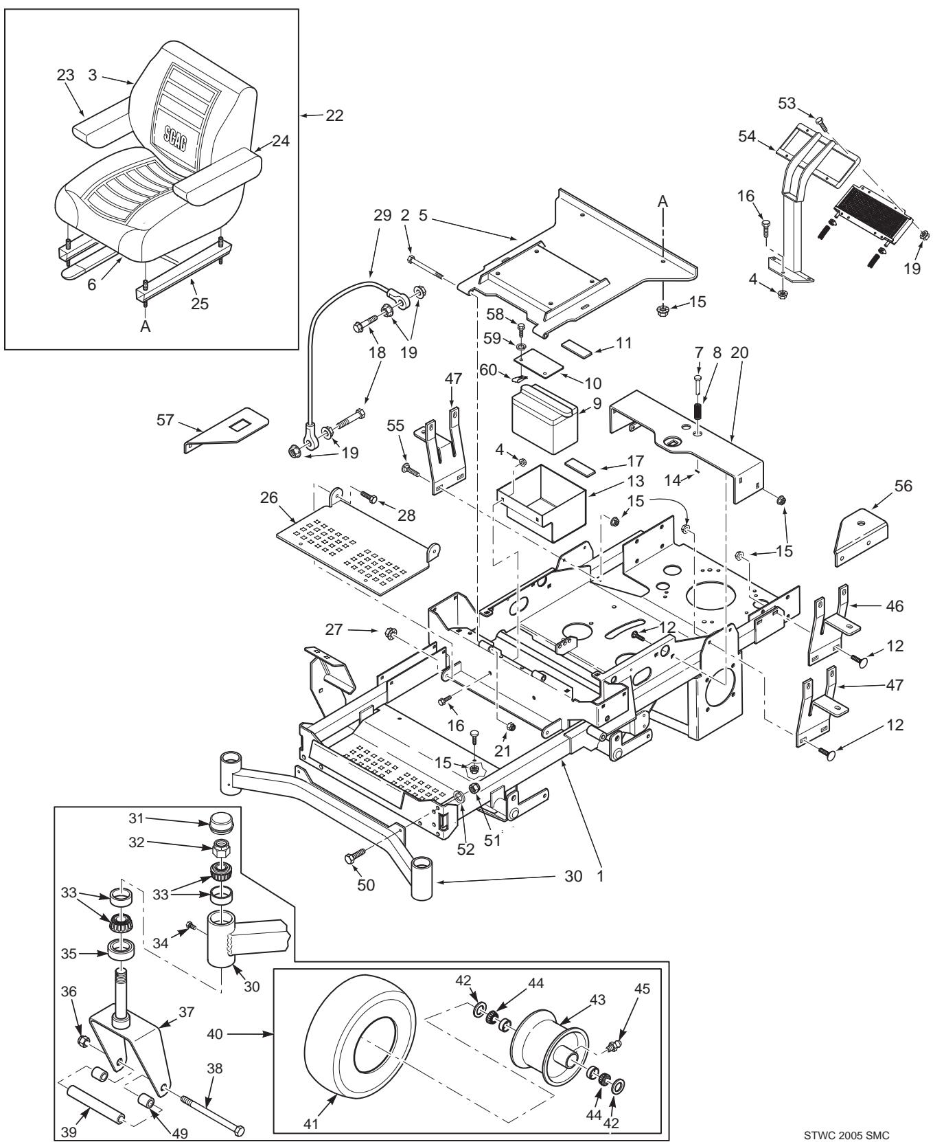
STWC 2005 SMC
SHEET METAL COMPONENTS
| Ref. No. | Part No. | Description | Ref. No. | Part No. | Description |
| 1 | 461740 | Main Frame Assembly w/decals | 31 | 481559 | Cap, Grease |
| 2 | 04001-73 | Bolt, Hex Head 5/16-18 x 3-3/4" | 32 | 04021-20 | Nut, Elastic Stop 1.0-14 |
| 3 | 482938 | Back Cover | 33 | 48668 | Bearing Set |
| 4 | 04019-04 | Nut, Serr. Flange 3/8-16 | 34 | 482028-01 | Plug, 1/4-28 |
| 5 | 451461 | Plate, Seat Mounting | 35 | 481025 | Seal, 2.0" OD x 1.625" ID |
| 6 | 482939 | Cushion Cover | 36 | 04021-07 | Nut, Elastic Stop 1/2-13 |
| 7 | 43462 | Pin Retainer, Spring | 37 | 451658 | Yoke, Front Caster Wheel |
| 8 | 481389 | Spring | 38 | 04001-167 | Bolt, Hex Head 1/2-13 x 9-1/2" |
| 9 | ** | Battery (not available through Scag) | 39 | 43583 | Sleeve |
| 10 | 423571 | Battery Cover | 40 | 482504 | Caster Wheel Assembly (Incl. 41 thru 45) |
| 11 | 482553 | Battery Hold Down Pad | 41 | 482619 | Tire, 13 x 6.5 Smooth |
| 12 | 04003-12 | Bolt, Carr. 5/16-18 x 3/4" | 42 | 482622 | Seal |
| 13 | 423556 | Battery Box | 43 | 482620 | Rim (Includes Item 45) |
| 14 | 04060-01 | Roll Pin, Spring 5/32 x 3/4" | 44 | 482621 | Roller Bearing |
| 15 | 04019-03 | Nut, Serr. Flange 5/16-18 | 45 | 48114-04 | Fitting, Grease |
| 16 | 04001-19 | Bolt, Hex Head 3/8-16 x 1" | 46 | 423575 | Mounting Bracket, Oil Tank |
| 17 | 482552 | Pad, Rubber | 47 | 423764 | Mounting Bracket, Fuel Tank |
| 18 | 04001-59 | Bolt, Hex Head 1/4-20 x 1-1/4" | 48 | 482633 | Seat Pan |
| 19 | 04019-02 | Nut, Serr. Flange 1/4-20 | 49 | 43584 | Spacer, Caster Wheel |
| 20 | 451462 | Seat Base Support | 50 | 04001-28 | Bolt, Hex Head 7/16-14 x 1-1/4" |
| 21 | 04021-10 | Nut, Elastic Stop 5/16-18 | 51 | 04021-11 | Nut, Elastic Stop 7/16-14 |
| 22 | 482840 | Seat Assembly w/ adj. rails | 52 | 04030-05 | Lockwasher, 7/16 |
| 23 | 482616 | Armrest Cover | 53 | 04001-06 | Bolt, Hex Head 1/4-20 x 5/8" |
| 482618 | Armrest, RH | 54 | 451580 | Support Weldment, Oil Cooler | |
| 24 | 482616 | Armrest Cover | 55 | 04003-04 | Bolt, Carriage 5/16-18 x 1" |
| 482617 | Armrest, LH | 56 | 423912 | Bracket, Fuel Valve | |
| 25 | 482937 | Seat Track Set | 57 | 424112 | Bracket, Hour Meter |
| 26 | 423557 | Footplate | 58 | 04001-32 | Bolt, Hex Head 3/8-16 x 1-1/4" |
| 27 | 04021-09 | Nut, Elastic Stop 3/8-16 | 59 | 04030-04 | Lock Washer. 3/8 Spring |
| 28 | 04001-19 | Bolt, Hex Head 3/8-16 x 1" | 60 | 04110-03 | U-Nut, 3/8-16 |
| 29 | 48566 | Cable, Seat Stop | |||
| 30 | 451666 | Weldment, Caster Support (61A) | |||
| 451470 | Weldment, Caster Support (52A) |
STWC ROLL OVER PROTECTION SYSTEM

STWC ROLL OVER PROTECTION SYSTEM
| Ref. | Part | |
| No. | No. | Description |
1 461816 STC ROPS
2 04001-145 Bolt, Hex Head 1/2-13 x 3-1/2"
3 04021-19 Nut, Center Lock 1/2-13
4 483150 Seat Belt
5 04040-13 Flatwasher, 1/2-.562 x 1.375 x .109
DRIVE SYSTEM COMPONENTS

DRIVE SYSTEM COMPONENTS
| Ref. No. | Part No. | Description |
| 1 | 04021-09 | Nut, Elastic Stop 3/8-16 |
| 2 | 04019-04 | Nut, Serrated Flange 3/8-16 |
| 3 | 483087 | Spring, Pump Idler |
| 4 | 43286 | Spacer |
| 5 | 04001-22 | Bolt, Hex Head 3/8-16 x 2-3/4" |
| 6 | 461603 | Idler Arm Assy., Pump Drive |
| 7 | 04063-14 | Key, 5 x 5 x 25mm |
| 8 | 483084 | Belt, Transmission |
| 9 | 481048 | Pulley, 3" Dia. Idler |
| 10 | 04043-04 | Flatwasher, 3/8-.391 x .938 x .105 |
| 11 | 482744 | Pulley, 5.75 OD Taper Bore |
| 12 | 482085 | Hub, Tapered, 15mm Bore |
| 13 | 04001-45 | Bolt, 3/8-16 x 2" |
| 14 | 43503 | Pivot, Idler |
| 15 | 48224 | Bearing |
| 16 | 04001-172 | Bolt, Hex Head 1/4-20 x 1" Grade 8 |
| 17 | 04001-31 | Bolt, Hex Head 3/8-16 x 2-1/2" |
| 18 | 04001-20 | Bolt, Hex Head 3/8-16 x 1-1/2" |
| 19 | 483081 | Pulley, 5.75" Dia. - 1-1/8" Bore |
| 20 | 421203 | Clamp Plate |
| 21 | 04017-05 | Hex Head Capscrew, 1/4-20 x 3/4" |
| 22 | 422969 | Control Lever, Pump |
| 23 | 04017-05 | Hex Head Capscrew, 1/4-20 x 3/4" |
| 24 | 04030-02 | Lockwasher, 1/4" |
| 25 | 48829 | Block, Pump Control |
| 26 | 04060-06 | Roll Pin |
| 27 | 04001-136 | Bolt, Hex Head 3/8-16 x 1-1/2" Grade 8 |
| 28 | 04019-04 | Nut, Serr. Flange 3/8-16 |
| 29 | 04001-136 | Bolt, Hex Head 3/8-16 x 1-1/2" Grade 8 |
| 30 | 424137 | Bracket |
| 31 | 04001-19 | Bolt, Hex Head 3/8-16 x 1" |
| 32 | 482416 | Pulley, 5" Dia. Idler |
ENGINE AND ATTACHING PARTS

SC 2004 EAPKA
ENGINE AND ATTACHING PARTS
| Ref. No. | Part No. | Description |
| 1 | 482900 | Engine, 27HP Kohler |
| 482827 | Engine, 25HP Kawasaki | |
| 2 | 423770 | Bumper, Rear |
| 3 | 41031 | Weight, Rear (Shield) 61A Only |
| 424107 | Shield, Rear 52A Only | |
| 4 | 04019-04 | Nut, Serr. Flange 3/8-16 |
| 5 | 482510 | Extension, Oil Drain 4” - Kohler |
| 482349 | Extension, Oil Drain 2.3” - Kawasaki | |
| 6 | 04003-23 | Bolt, Carr. 3/8-16 x 1” |
| 7 | 04001-32 | Bolt, Hex Head 3/8-16 x 1-1/4” |
| 8 | 482907 | Muffler - Kohler |
| 482697 | Muffler - Kawasaki | |
| 9 | 423572 | Bracket, Muffler |
| 10 | 423555 | Plate, Skid |
| 11 | 04001-11 | Bolt, Hex Head 5/16-18 x 1-1/2” |
| 12 | 04001-19 | Bolt, Hex Head 3/8-16 x 1” |
| 13 | 04003-12 | Bolt, Hex Head 5/16-18 x 3/4” |
| 14 | 04019-03 | Nut, Serr. Flange 5/16-18 |
| 15 | 04001-32 | Bolt, Hex Head 3/8-16 x 1-1/4” |
| 16 | 04019-03 | Nut, Serr. Flange 5/16-18 |
STEERING COMPONENTS

STC 2002 SSC
STEERING COMPONENTS
| Ref. No. | Part No. | Description |
| 1 | 482340 | Grip, Control Lever |
| 2 | 461386 | Handle Bar (Includes item 1) |
| 3 | 04001-32 | Bolt, Hex Head 3/8-16 x 1-1/4" |
| 4 | 04030-04 | Lock Washer, 3/8" |
| 5 | 04041-07 | Flatwasher, 3/8-.391 x .938 x .105 |
| 6 | 04040-15 | Flatwasher, 5/16-.375 x .875 x .083 |
| 7 | 04060-01 | Roll Pin, Spring 5/32 x 3/4" |
| 8 | 422372 | Bar, Control Lever |
| 9 | 04021-09 | Nut, Elastic Stop 3/8-16 |
| 10 | 482330 | Rod End, 3/8-24 RH Female |
| 11 | 04020-14 | Nut, 3/8-24 RH Thread |
| 12 | 482623 | Rod, Pump Control Linkage |
| 13 | 04020-17 | Nut, 3/8-24 UNF-2B LH Thread |
| 14 | 482331 | Rod End, 3/8-24 LH Thread |
| 15 | 43477 | Pin Retainer |
| 16 | 04001-20 | Bolt, Hex Head 3/8-16 x 1-1/2" |
| 17 | 04001-12 | Bolt, Hex Head 5/16-18 x 1-3/4" |
| 18 | 43602 | Spacer, Pump Dampener |
| 19 | 423599 | Plate, Control Lever |
| 20 | 04001-17 | Bolt, Hex Head 5/16-18 x 2" |
| 21 | 482452 | Gas Damper |
| 22 | 04001-19 | Bolt, Hex Head 3/8-16 x 1" |
| 23 | 482099 | Block, Clamping |
| 24 | 04003-12 | Bolt, Carriage, 5/16-18 x 3/4" |
| 25 | 461525 | Control Plate - LH (Includes Decal) |
| 461526 | Control Plate - RH (Includes Decal) | |
| 26 | 04019-03 | Nut, Serr., Flange, 5/16-18 |
| 27 | 04021-08 | Nut, Elastic Stop 1/4-20 |
| 28 | 04001-18 | Bolt, Hex Head 3/8-16 x 3/4" |
| 29 | 43616 | Shaft, Steering Control |
| 30 | 04021-10 | Nut, Elastic Stop 5/16-18 |
| 31 | 48114-04 | Grease Fitting, 1/4-28 Self Tap |
| 32 | 43559 | Spacer, Control |
| 33 | 49574 | Control Lever Assy RH (Includes 31 & 35) |
| 49573 | Control Lever Assy LH (Includes 31 & 35) | |
| 34 | 04021-10 | Nut, Elastic Stop 5/16-18 |
| 35 | 48100-06 | Bushing |
| 36 | 04041-08 | Flatwasher, 1-1/4 x 49/64 x 16 Ga. |
| 37 | 04050-02 | Retaining Ring, 3/4" Ext. |
| 38 | 423057 | Bracket, Switch Actuator |
| 39 | 04017-16 | Bolt, Hex Serr. Flange 5/16-18 x 3/4" |
| 40 | 04003-02 | Bolt, Carr. 1/4-20 x 3/4" |
| 41 | 45918 | Bracket, Control Return |
| 42 | 481389 | Spring |
| 43 | 43477 | Pin Retainer |
BRAKE COMPONENTS

STC 2002 BSC
BRAKE COMPONENTS
| Ref. No. | Part No. | Description |
| 1 | 04019-04 | Nut, Serr. Flange 3/8-16 |
| 2 | 48807 | Spring |
| 3 | 04001-08 | Bolt, Hex Head 5/16-18 x 3/4" |
| 4 | 04001-163 | Bolt, Hex Head 1/2-13 x 3-3/4" |
| 5 | 04001-52 | Bolt, Hex Head 1/2-13 x 2-1/2" |
| 6 | 04021-19 | Nut, 1/2-13 Center Lock |
| 7 | 482639 | Wheel Motor Ross |
| 8 | 04063-25 | Key, Woodruff 5/16 x 1" |
| 9 | 461438 | Wheel Hub Assembly |
| 10 | 481601 | Brake Band Assembly |
| 11 | 482061 | Bushing, Self Align |
| 12 | 48680 | Nut, Hex Castle 1.0-20 UNEF |
| 13 | 04061-06 | Cotter Pin, 9/64 x 1-1/2" |
| 14 | 04028-02 | Lug Nut, 1/2-20 |
| 15 | 482413 | (52") Wheel Assembly 23 x 9.5 -12 |
| 481850 | (61") Wheel Assembly 24 x 12 - 12 | |
| 482414 | (52") Rim | |
| 481851 | (61") Rim w/Stem | |
| 482194 | (52") Tire 23 x 9.5 - 12 | |
| 481852 | Tire 24 x 12 - 12 | |
| 16 | 04004-46 | Brake Rod Stud, 3/8-24 x 8.125 |
| 17 | 04020-14 | Nut, 3/8-24 UNF |
| 18 | 423279 | Plate Weldment, Motor Backing |
| 19 | 04064-16 | Clevis Pin, 3/8 x 1.93" |
| 20 | 04069-01 | Pin, Rue Cotter 3/8 Dia. |
| 21 | 461471 | Brake Linkage LH |
| 461472 | Brake Linkage RH | |
| 22 | 48114-04 | Grease Fitting, 1/4-28 |
| 23 | 04020-25 | Nut, 3/8-24 UNF |
| 24 | 04050-01 | Retaining Ring, .625 Ext. |
| 25 | 04021-10 | Nut, Elastic Stop 5/16-18 |
| 26 | 04041-07 | Flatwasher, 3/8-.391 x .938 x .105 |
| 27 | 04001-31 | Bolt, Hex Head 3/8-16 x 2-1/2" |
| 28 | 04001-166 | Bolt, Hex Head 3/8-24 x 3-3/4" |
| 29 | 04061-02 | Cotter Pin, 3/32 x 3/4" |
| 30 | 04001-20 | Bolt, Hex Head 3/8-16 x 1-1/2" |
| 31 | 451463 | Brake Shaft |
| 32 | 04021-09 | Nut, Elastic Stop 3/8-16 |
| 33 | 48544 | Rod End, 3/8-24 LH Thread |
| 34 | 04064-02 | Clevis Pin, 3/8 x 1.06 |
| 35 | 48343-04 | Clevis, 3/8-24 |
| 36 | 482102 | Grip, Brake Lever |
| 37 | 04019-04 | Nut, Serr. Flange 3/8-16 |
| 38 | 461509 | Brake Lever (includes item 36) |
| 39 | 04001-22 | Bolt, Hex Head 3/8-16 x 2-3/4" |
| 40 | 04020-17 | Nut, 3/8-24 UNF-2B LH Thread |
| 41 | 422483 | Lever, Brake |
| 42 | 45974 | Shaft Weldment, Pivot |
| 43 | 43495 | Pin, Pivot |
| 44 | 04008-01 | Bolt, Serr. Flange 1/2-20 x 4.563" |
FUEL AND HYDRAULIC SYSTEM

STWC 2005 FHS
FUEL AND HYDRAULIC SYSTEM
| Ref. No. | Part No. | Description | Ref. No. | Part No. | Description |
| 1 | 482643 | Pump, BDP-10A-316 (L.H.) | 30 | 482572 | Elbow, 0.38 Hose |
| 482644 | Pump, BDP-10A-419 (R.H.) | 31 | 48136-13 | Clamp | |
| 2 | 482266-01 | Elbow, 90 Degree 9/16 O-Ring x 3/8 Hose | 32 | 48058 | Fuel Hose, 1/4 ID |
| 3 | 48572-02 | Fitting, 1/2” JIC x 5/8 O-Ring | 33 | 423912 | Bracket Fuel Valve |
| 4 | 48811 | Hose, 3/8 Pushlock (Specify length) | 34 | 48059-01 | Clamp, Fuel Hose 1/4 Hose ID |
| 5 | 482573 | Bushing | 35 | 482212 | Valve, Fuel Shutoff |
| 6 | 482574 | Fitting | 36 | 48136-13 | Clamp, .69 Max. / .25 Min. Dia. |
| 7 | 482266-01 | Elbow, 90 Degree 9/16 O-Ring x 3/8 Hose | 37 | 482800-02 | Fitting, 9/16 O-Ring x 3/8 Hose |
| 8 | 48136-13 | Hose Clamp, .69 Dia. | 38 | 04019-03 | Nut, Serr. Flange 5/16-18 |
| 9 | 482548 | Hose Assembly | 39 | 04041-07 | Flatwasher, 3/8-.391 x .938 x .105 |
| 10 | 04060-06 | Roll Pin | 40 | 48462-01 | Oil Filter |
| 11 | 48572-04 | Fitting, 1/2” JIC x 1/2” O-Ring | 41 | 482798 | Filter Head Assembly |
| 12 | 48603-06 | O-Ring | 42 | 482800-01 | Fitting, 3/4 O-Ring x 3/8 Hose |
| 13 | 04001-20 | Bolt, Hex Head 3/8-16 x 1-1/2” | 43 | 48604-03 | Plug, 9/16-18 O-Ring |
| 14 | 04017-07 | Bolt, Hex Head 1/4-20 x 1-1/4” | 44 | 482557 | Hose, Filter Inlet |
| 15 | 04030-02 | Lockwasher | 45 | 461718 | Fuel Tank RH |
| 16 | 04021-09 | Nut, Elastic Stop 3/8-16 | 46 | 482547 | Cap, Fuel Tank (incl. item #53) |
| 17 | 422969 | Control Lever | 47 | 48309 | Tank Bushing |
| 18 | 04001-08 | Bolt, Hex Head 5/16-18 x 3/4” | 48 | 48939 | Elbow, 90 Degree |
| 19 | 04030-03 | Lockwasher, 5/16 | 49 | 461698 | Fuel Tank LH |
| 20 | 04040-15 | Flatwasher, 5/16-.375 x .875 x .083 | 50 | 48811 | Hose, 3/8 Pushlock 15” Long |
| 21 | 481164 | Cap, Hydraulic Tank | 51 | 482708 | Cooler, Transmission |
| 22 | 481507 | Insert, Filler Neck | 52 | 04010-10 | Screw, 1/4-20 x 2” |
| 23 | 48829 | Control Block | 53 | 482774 | Gasket, Gas Tank Cap |
| 24 | 421203 | Clamp Plate | 54 | ** | Fuel Filter |
| 25 | 461479 | Hydraulic Tank Assembly w/fittings | 55 | 482605 | Hose Assembly |
| 26 | 48603-06 | O-Ring | 56 | 04001-11 | Bolt, Hec Head 5/16-18 x 1-1/2 |
| 27 | 482277 | Tee Fitting, O-Ring to Barb | 57 | 482802 | Nipple, Oil Filter 1.0-12 UNF-2A x 1-1/4” |
| 28 | 48136-13 | Clamp, .69 Max. / .25 Min. Dia. | 58 | 04001-17 | Bolt, Hex Head 5/16-18 x 2” |
| 29 | 482571 | Bushing | 59 | 48603-02 | O-Ring, 3/4” |
** Available through the individual engine manufacturer.
ELECTRICAL SYSTEM

STWC 2005 ESKH
ELECTRICAL SYSTEM
| Ref. No. | Part No. | Description |
| 1 | 483072 | Hourmeter |
| 2 | 48298 | Fuse, 20 amp |
| 3 | 48017-02 | Key, Ignition |
| 4 | 48017-04 | Nut, Hex 5/8-32 |
| 5 | 48017-03 | Lockwasher, 5/8” Internal |
| 6 | 461660 | Electric PTO Clutch GT3.5 |
| 7 | 48798 | Switch, Ignition |
| 8 | 481687 | Switch, PTO |
| 9 | 48788 | Relay |
| 10 | 04031-01 | Lock Washer, #10 External Tooth |
| 11 | 04020-01 | Nut, Hex #10-32 |
| 12 | 481637 | Switch, N/O |
| 13 | 461768 | Panel, Instrument |
| 14 | 481544 | Choke Control - Kohler (Qty 1) |
| 482032 | Choke & Throttle Control - Kawasaki (Qty 2) | |
| 15 | 48030-09 | Clamp |
| 16 | 481638 | Switch, Seat |
| 17 | 483029 | Module, Interlock |
| 18 | 04010-01 | Screw, #10-32 x .5” Phillips Head |
| 19 | ** | Battery (Not Available Through Scag) |
| 20 | 04001-44 | Bolt, Hex Head 1/4-20 x .5” |
| 21 | 04020-02 | Nut, Hex 1/4-20 |
| 22 | 48029-15 | Cable, Battery Black (negative) |
| 23 | 48029-12 | Cable, Battery Red (positive) |
| 24 | 483053 | Wiring Harness, Main |
| 25 | 483081 | Pulley, 5.45 OD x 1.125 Bore |
| 26 | 04021-10 | Nut, Elastic Stop 5/16-18 Key |
| 27 | 424112 | Mounting Bracket, Hour Meter |
| 28 | 04010-11 | Screw, #10-32 x 1.5” Phillips Head |
| 29 | 482543 | Adaptor, Wiring Harness |
| 30 | 04063-23 | Key, 1/4 x 1/4 x 3-1/4” |
| 31 | 04041-28 | Flatwasher, 7/16-.469 x 1-3/4” x 1/4” |
| 32 | 04030-05 | Lockwasher, 7/16” |
| 33 | 04102-03 | Bolt, Hex Head 7/16-20 x 2-1/4” UNF (61A Only) |
| 34 | 04010-12 | Screw, #10-32 x 3/4” |
| 35 | 04001-08 | Bolt, Hex Head 5/16-18 x 3/4” |
| 36 | 04030-03 | Lockwasher, 5/16 |
| 37 | 04040-15 | Flatwasher, 5/16-.375 x .875 x .083 |
| 38 | 423909 | Backing Plate |
| 39 | 481716 | Rubber Pad, Clutch Stop |
| 40 | 422534 | Plate, Backing |
| 41 | 482032 | Throttle Control - Kohler & Kawasaki ( Qty 1) |
HYDRAULIC PUMP ASSEMBLY

HYDRAULIC PUMP ASSEMBLY
| Ref. No. | Part No. | Description |
| 1 | HG 70516 | Housing Kit |
| 2 | HG 70573 | End Cap Kit |
| 3 | HG 50641 | Straight Headless Pin |
| 4 | HG 50969 | Hex Flange Bolt, M8-1.25 x 60mm |
| 5 | HG 51232 | Housing O-Ring |
| 6 | HG 2513027 | Charge Pump Kit |
| 7 | HG 50273 | Gerotor Assembly |
| 8 | HG 9004101-1340 | O-Ring |
| 9 | HG 50095 | Socket Head Screw, M6 x 1.0-20mm |
| 10 | HG 2513030 | Bypass Valve Kit |
| 11 | HG 70521 | Pumpshaft Kit |
| 12 | HG 50315 | Ball Bearing, 17 x 40 x 12 |
| 13 | HG 51161 | Lip Seal |
| 14 | HG 50329 | Retaining Ring |
| 15 | HG 50951 | Spacer |
| 16 | HG 70331 | Cylinder Block Kit |
| 17 | HG 2003014 | Block Spring |
| 18 | HG 2003017 | Block Thrust Washer |
| 19 | HG 51444 | Valve Plate |
| 20 | HG 2003087 | Swash Plate |
| 21 | HG 50551 | Ball Thrust Bearing |
| 22 | HG 2003005 | Trunnion Arm |
| 23 | HG 2000015 | Slot Guide |
| 24 | HG 2510062 | Check Valve Kit (.024" Orifice) port “A” on Left Hand Pump, port “B” on Right Hand Pump |
| 25 | HG 70403 | Charge Relief Kit |
| 26 | HG 2513043 | Trunnion Seal with Retainer |
| 27 | HG 9005110-4400 | Straight Thread Plug |
| 28 | HG 50408 | Straight Headless Pin |
| 29 | HG 70525 | Overhaul Seal Kit |
| 30 | HG 70743 | System Check Relief Kit, port “B” on Left Hand Pump, port “A” on Right Hand Pump |
* Common hardware which should be purchased locally. All bolts Grade 5 plated, all other fasteners zinc plated.
REPLACEMENT DECALS AND INFORMATION PLATES

1

2



13

6

7

9


19

11
STWC 2005 RDP1
REPLACEMENT DECALS AND INFORMATION PLATES
| Ref. No. | Part No. | Description |
| 1 | 482285 | Decal, Danger-Spinning Blades |
| 2 | 482286 | Decal, Warning-Rotating Blades |
| 3 | 481954 | Decal, 52A |
| 481955 | Decal, 61A | |
| 4 | 481425 | Decal, Oil |
| 5 | 483044 | Decal, Patents |
| 6 | 482100 | Decal, Traction Control |
| 7 | 481971 | Decal, Heavy Duty Commercial |
| 8 | 48404 | Decal, Metalcraft - Made in USA |
| 9 | 481039 | Decal, Belt Cover |
| 10 | 482982 | Decal, Instrument Panel |
| 11 | 482835 | Decal, Fuel Valve Position |
| 12 | 482566 | Decal, Cutting Height Bottom Row of Holes |
| 13 | 482906 | Decal, Wildcat |
| 14 | 482709 | Decal, Seat Support |
| 15 | 482905 | Decal, Rear Bumper |
| 16 | 482166 | Decal, Front Footplate |
| 17 | 482165 | Decal, Discharge Chute |
| 18 | 482549 | Decal, Cutting Height Top Row of Holes |
| 19 | 482834 | Decal, ROPS |
IMPORTANT ADJUSTMENT PROCEDURES
READ OPERATOR'S MANUAL FOR MORE DETAILS
Check tire pressure - (Drive tires-12 psi)
- (Caster tires-25 psi)


Rotate turnbuckle
With an operator in the seat, engine running, control
lever in neutral and the parking brake disengaged.
adjust control linkage. Loosen jam nuts. If wheel
rotates forward, adjust turnbuckle CW. If wheel
rotates rearward, adjust turnbuckle CCW. Adjust until
drive wheel stops turning. Tighten Jam nuts. Repeat
procedure until proper Neutral Adjustment is obtained.
TRACKING ADJUSTMENT
If the machine pulls to the right, adjust LH control
Linkage CW to slow left wheel. If the machine pulls to
the left adjust RH control linkage CW to slow right
wheel. Readjust neutral if necessary.
To move machine without running the engine, rotate
both dump valves located at the LH side of the pumps
CCW 1/2 turn to "freewheel" positions. Return dump
valves to original position to operate the mower.
Tighten to 7-10 ft-lbs.
HYDRAULIC FLUID LEVEL
Check hydraulic fluid level
while fluid is cool. Fluid
level should be 3' below top
of filler neck. Fill with
SAE 20W50 motor oil only.
IMPORTANT
Do not overfill. Room
for hot fluid expansion
must be allowed or }
sulting expansion may
leaks system.
482709
SCAG
482905
WILDCAT
15
61 Advantage
3
SCAG®
482166
16
WARNING
DO NOT OPERATE WITHOUT DISCHARGE CHUTE, MULCHING
KIT, OR ENTIRE GRASS CATCHER INSTALLED 482165
17
SC 2004 RDP2
ELECTRICAL SCHEMATIC

Any part of the Scag commercial mower manufactured by Scag Power Equipment and found, in the reasonable judgment of Scag, to be defective in materials or workmanship, will be repaired or replaced by an Authorized Scag Service Dealer without charge for parts and labor. This warranty is limited to the original purchaser and is not transferable. Proof of purchase will be required by the dealer to substantiate any warranty claims. All warranty work must be performed by an Authorized Scag Service Dealer.
This warranty is limited to the following specified periods from the date of the original retail purchase for defects in materials or workmanship:
* Wear items including drive belts, blades, hydraulic hoses and tires are warranted for ninety (90) days.
* Batteries are covered for ninety (90) days.
* Frame and structural components including oil reservoir, fittings, and oil coolers are warranted for 2 years (Parts and labor 1st year; Parts only 2nd year).
* Cutter decks are warranted against cracking for a period of three (3) years. (Parts and labor 1st year; Parts only 2nd and 3rd year) The repair or replacement of the cutter deck will be at the option of Scag Power Equipment. We reserve the right to request components for evaluation. This warranty does not cover any mower that has been subject to misuse, neglect, negligence, or accident, or that has been operated in any way contrary to the operating instructions as specified in the Operator's Manual.
* Engines and electric starters are covered by the engine manufacturer's warranty period.
* Major drive system components are warranted for two (2) years by Scag Power Equipment. (Parts and labor 1st year; Parts only 2nd year) (Two year warranty exclude fittings, hoses, drive belts). The repair or replacement of the hydraulic pump or hydraulic motor will be at the option of Scag Power Equipment. This warranty does not cover any mower that has been subject to misuse, neglect, negligence, or accident, or that has been operated in any way contrary to the operating instructions as specified in the Operator's Manual.
* Electric clutches have a Limited Warranty for 2 year (Parts and labor 1st year; Parts only 2nd year).
* Cutter Spindle Assemblies 46631 have a Limited Warranty for three years (Parts and labor 1st year; Parts only 2nd and 3rd year).
* Any Scag product used for rental purposes is covered by a 90 day warranty.
The Scag mower, including any defective part must be returned to an Authorized Scag Service Dealer within the warranty period. The expense of delivering the mower to the dealer for warranty work and the expense of returning it to the owner after repair will be paid for by the owner. Scag's responsibility is limited to making the required repairs and no claim of breach of warranty shall be cause for cancellation or rescission of the contract of sale of any Scag mower.
This warranty does not cover any mower that has been subject to misuse, neglect, negligence, or accident, or that has been operated in any way contrary to the operating instructions as specified in the Operator's Manual. The warranty does not apply to any damage to the mower that is the result of improper maintenance, or to any mower or parts that have not been assembled or installed as specified in the Operator's Manual and Assembly Manual. The warranty does not cover any mower that has been altered or modified, changing performance or durability. In addition, the warranty does not extend to repairs made necessary by normal wear, or by the use of parts or accessories which, in the reasonable judgment of Scag, are either incompatible with the Scag mower or adversely affect its operation, performance or durability.
Scag Power Equipment reserves the right to change or improve the design of any mower without assuming any obligation to modify any mower previously manufactured. All other implied warranties are limited in duration to the two (2) year warranty period or ninety (90) days for mowers used for rental purpose. Accordingly, any such implied warranties including merchantability, fitness for a particular purpose, or otherwise, are disclaimed in their entirety after the expiration of the appropriate two year or ninety day warranty period. Scag's obligation under this warranty is strictly and exclusively limited to the repair or replacement of defective parts and Scag does not assume or authorize anyone to assume for them any other obligation. Some states do not allow limitations on how long an implied warranty lasts, so the above limitation may not apply to you.
Scag assumes no responsibility for incidental, consequential or other damages including, but not limited to, expense for gasoline, expense of delivering the mower to an Authorized Scag Service Dealer and expense of returning it to the owner, mechanic's travel time, telephone or telegram charges, rental of a like product during the time warranty repairs are being performed, travel, loss or damage to personal property, loss of revenue, loss of use of the mower, loss of time or inconvenience. Some states do not allow the exclusion or limitation of incidental or consequential damages, so the above limitation or exclusion may not apply to you. This warranty gives you specific legal rights, and you may also have other rights which vary from state to state.
Filtro DE COMBUSTIBLE
firmemente.
components electrics.

PALANCAS DE CONTROL DE VALVULA DE DESCARGA
corte desada.
3.3 TRACTOR (CONTINUATION)
25 HP (Espec. #FH721V) (Scag Modelo STWCS2A-25KA)
Potencia 27 HP (Espec. #) (Scag Modelo STWC61A-27CV)
Marca ....Kohler
opacouisang x sebih his do
(aurcidas eresudos internetores etc.)
ndou, ris, said, cns, 'souw' sns, cnidw, pbuw
* Mastercard library's major six hits y sul ronda
la maquinia.
MODETO STWC
POWER EQUIPMENT SCALE®



- WARNING
- FAILURE TO FOLLOW SAFE OPERATING PRACTICES MAY RESULT IN SERIOUS INJURY
- SCAG POWER EQUIPMENT®
- TABLE OF CONTENTS
- SUBJECT
- PAGE
- SECTION 1 - GENERAL INFORMATION
- SECTION 2 - SAFETY INFORMATION
- SECTION 3 - SPECIFICATIONS
- SECTION 4 - OPERATING INSTRUCTIONS
- SECTION 5 - TROUBLESHOOTING CUTTING CONDITIONS
- TABLE OF CONTENTS (CONT'D)
- SECTION 6 - ADJUSTMENTS
- SECTION 7 - MAINTENANCE
- SECTION 8 - REPLACEMENT PARTS
- GENERAL INFORMATION
- INTRODUCTION
- USE OF OTHER THAN ORIGINAL SCAG REPLACEMENT PARTS WILL VOID THE WARRANTY
- USE ONLY SCAG APPROVED ATTACHMENTS AND ACCESSORIES
- DIRECTION REFERENCE
- SERVICING THE ENGINE AND DRIVE TRAIN COMPONENTS
- SAFETY INFORMATION
- READ THIS OPERATOR'S MANUAL BEFORE ATTEMPTING TO START YOUR MOWER
- SIGNAL WORDS
- SIGNAL WORD
- DANGER
- CAUTION
- BEFORE OPERATION CONSIDERATIONS
- BEFORE OPERATION CONSIDERATIONS (CONT'D)
- NOTE
- OPERATION CONSIDERATIONS
- OPERATION CONSIDERATIONS (CONT'D)
- ROLL OVER PROTECTION SYSTEM
- MAINTENANCE CONSIDERATIONS & STORAGE
- SAFETY AND INSTRUCTIONAL DECALS
- START/DRIVE PROCEDURE
- IMPORTANT
- IMPORTANT ADJUSTMENT PROCEDURES
- READ OPERATOR'S MANUAL FOR MORE DETAILS
- NEUTRAL ADJUSTMENT
- TRACKING ADJUSTMENT
- HYDRAULIC FLUID LEVEL
- SPECIFICATIONS
- ENGINE
- ELECTRICAL
- TRACTOR
- TRACTOR (CONT'D)
- CUTTER DECK
- HYDRAULIC SYSTEM
- PRODUCTIVITY
- OPERATING INSTRUCTIONS
- CONTROLS AND INSTRUMENT IDENTIFICATION
- SAFETY INTERLOCK SYSTEM
- INITIAL RUN-IN PROCEDURES (FIRST DAY OF USE OR APPROXIMATELY 10 HOURS)
- STARTING THE ENGINE
- GROUND TRAVEL AND STEERING
- FORWARD TRAVEL
- REVERSE TRAVEL
- ENGAGING THE DECK DRIVE (CUTTER BLADES)
- PARKING THE MOWER
- AFTER OPERATION
- REMOVING CLOGGED MATERIAL
- ROTATING BLADES
- MOVING MOWER WITH ENGINE STOPPED
- RECOMMENDATIONS FOR MOWING
- ADJUSTING CUTTING HEIGHT
- TOWING (OPTIONAL HITCH ACCESSORY)
- ADJUSTMENTS
- PARKING BRAKE ADJUSTMENT
- TRAVEL ADJUSTMENTS
- THROTTLE CONTROL AND CHOKE ADJUSTMENTS
- BELT ADJUSTMENT
- BELT ALIGNMENT
- CUTTER DECK ADJUSTMENTS
- CUTTER DECK LEVEL
- CUTTER DECK PITCH
- CUTTER DECK HEIGHT
- CUSTOM-CUT BAFFLE ADJUSTMENT
- MAINTENANCE
- CHECKING HYDRAULIC OIL LEVEL
- CHANGING HYDRAULIC OIL
- CHANGING HYDRAULIC OIL FILTER ELEMENT
- ENGINE OIL
- CHECKING ENGINE CRANKCASE OIL LEVEL
- CHANGING ENGINE CRANKCASE OIL
- CHANGING ENGINE OIL FILTER
- ENGINE FUEL SYSTEM
- FILLING THE FUEL TANK
- ENGINE AIR CLEANER
- CLEANING AND/OR REPLACING AIR CLEANER ELEMENT
- BATTERY
- BATTERY ELECTROLYTE FIRST AID
- CHARGING THE BATTERY
- JUMP STARTING
- DRIVE BELTS
- CUTTER BLADES
- BLADE INSPECTION
- BLADE SHARPENING
- BLADE REPLACEMENT
- TIRES
- BODY, DECK, AND UPHOLSTERY
- NOTES
- SHEET METAL COMPONENTS
- STWC ROLL OVER PROTECTION SYSTEM
- HYDRAULIC PUMP ASSEMBLY
- REPLACEMENT DECALS AND INFORMATION PLATES
- SCAG
- WILDCAT
- ADVANTAGE
- SCAG®
- MODETO STWC
- POWER EQUIPMENT SCALE®
Brand : Scag
Model : STWC
Category : Lawn mower