
X-Connect - Inverter STUDER - Free user manual and instructions
Find the device manual for free X-Connect STUDER in PDF.
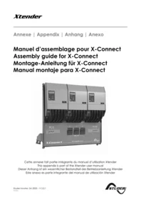


| Product type | Mounting frame for Xtender inverters |
| Brand | STUDER |
| Model | X-Connect |
| Compatibility | Xtender inverters from the XTH series, centralized, parallel, three-phase, and parallel + three-phase systems |
| Maximum number of inverters | 9 (3 X-Connect systems) |
| Maximum total power | 72 kW |
| Included DC circuit breakers | 3 x 400 A |
| Included DC fuses | 3 x 400 A |
| Included DIN rails | Yes |
| Included wiring accessories | Interconnection tubes, cable glands, 90 mm² DC cable with lugs |
| Cable entry holes | 4 of Ø 50 mm on each side |
| Ventilation | Provide ventilation space, do not obstruct the lower openings of the frame |
| Power supply | No dedicated power supply, powered by the Xtender inverters |
| Dimensions (estimate) | Approximately 800 x 600 x 300 mm |
| Weight (estimate) | Approximately 35 kg |
| Main functions | Simplifies wiring of multi-Xtender systems, allows easy by-pass during maintenance |
| Care and cleaning | Clean with a dry cloth, regularly inspect connections and fuses |
| Safety | Installation by a qualified professional, disconnect power before any intervention |
| Spare parts and repairability | Circuit breakers, fuses, cable glands, cables, and fasteners are replaceable |
| General information | Appendix to the Xtender manual, manual available in several languages |
Frequently Asked Questions - X-Connect STUDER
User questions about X-Connect STUDER
0 question about this device. Answer the ones you know or ask your own.
Ask a new question about this device
Download the instructions for your Inverter in PDF format for free! Find your manual X-Connect - STUDER and take your electronic device back in hand. On this page are published all the documents necessary for the use of your device. X-Connect by STUDER.
USER MANUAL X-Connect STUDER
Cabling flexibility* 5
Multi X-Connect systems....5
DEUTSCH....6
Vorwort 6
Einführung 7
Lieferumfang 7
This appendix contains assembly instructions for the mounting frame X-Connect and is an integral part of the Xtender user manual. Before using this product, carefully read the safety instructions included in the Xtender user manual.
INTRODUCTION
Congratulations! You just purchased the X-Connect, a mounting frame to assemble a multi-Xtender system.
The X-Connect will offer you a flexible and economical solution for high power systems based on inverters from the XTH product range. Indeed, it will make the cabling of centralized, parallel, 3-phase or even parallel + 3-phase systems much easier.
Supply list

In order to simplify the installation of an X-Connect system as much as possible, the mounting frame is supplied with the following items:
Pre-installed DC circuit breakers 3 x 400A
Pre-installed DC fuses 3 x 400A
Pre-installed DIN rails
Interconnection pipes and glands for auxiliary contacts wiring Interconnection pipe and gland for AC wiring
Interconnection pipes and glands + 90mm 2 wire terminated with appropriates ring tongues for DC wiring from Xtender to breakers and fuses
Screws set for frame assembly.
Cabling flexibility*
The X-Connect has been designed to offer a large range of cabling possibilities in order to best adapt to each environment.
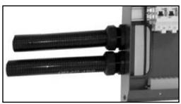
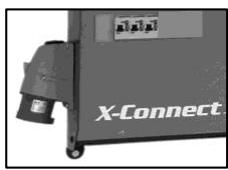
Four 50 mm holes on each side of the frame enable input and output cabling (AC and/or DC) by either plugs/sockets or glands or installation channels. These inputs/outputs can likewise be carried out downwards via channels. If this later solution is chosen, the installer will take care not to seal the apertures down of the fixing frame. These apertures allow on one side the cables input and on the other side the Xtender ventilation air entrance.
Studer Innotec highly recommends the installation of plugs/sockets at the input/output of the system. This allows a simple and secure by-pass of the system during maintenance operations.
Multi X-Connect systems
It is possible to combine up to 9 Xtender inverter/chargers (3 X-Connect systems) allowing to reach a total power of 72kW.
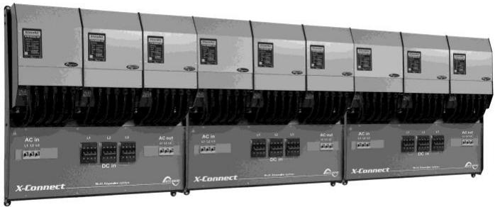
*The output cabling as well as the glands (or 400VAc plug and socket) are not supplied with the X-Connect.
DEUTSCH
VORWORT
LISTE DES PIÈCES – LIST OF PARTS – STÜCKLISTE – LISTA DE PIEZAS
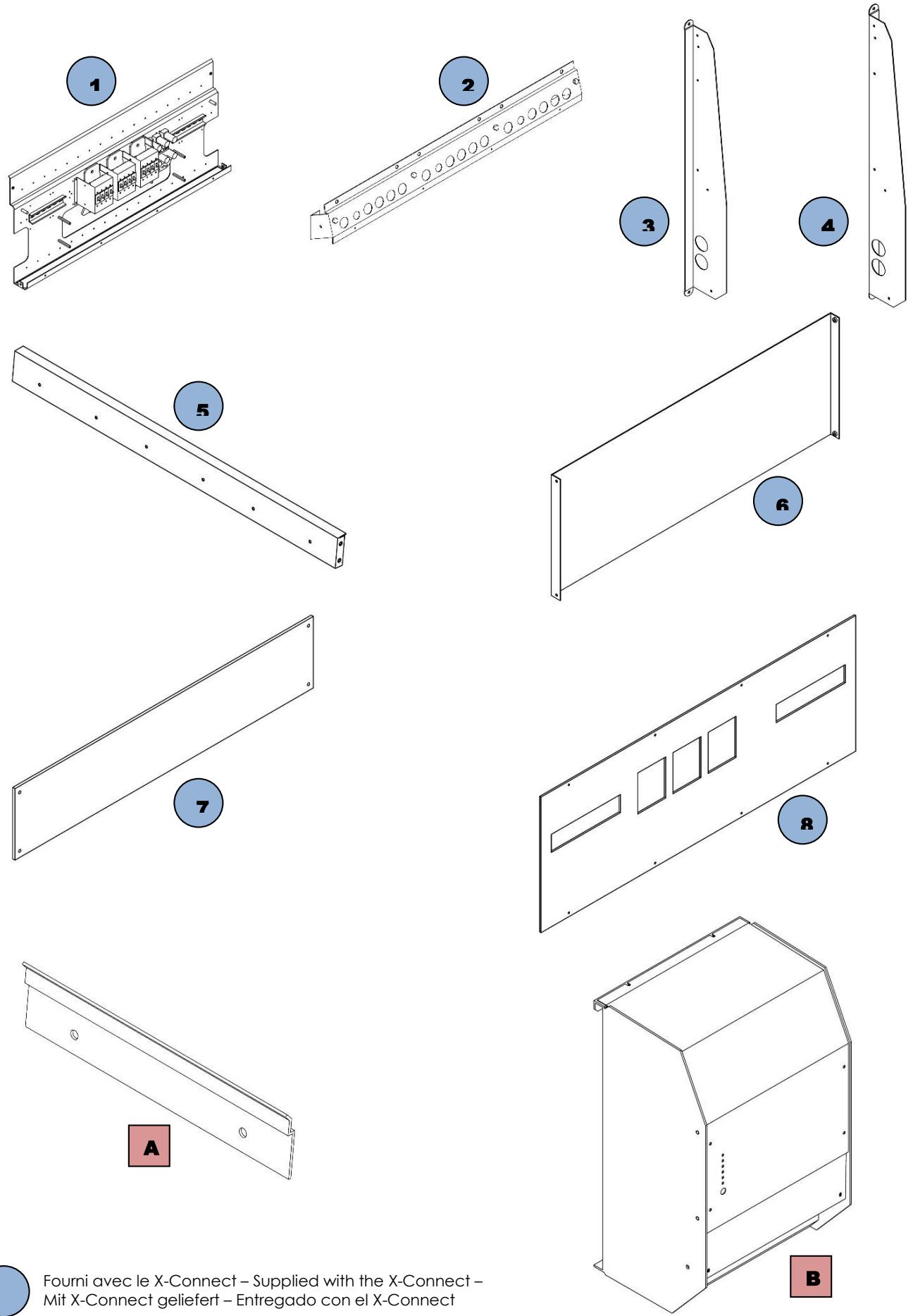

Fourni avec le X-Connect – Supplied with the X-Connect – Mit X-Connect geliefert – Entregado con el X-Connect

Fourni avec le XTH – Supplied with the XTH – Mit XTH geliefert – Entregado con el XTH
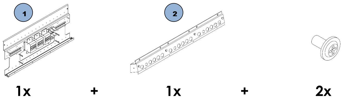
MONTAGE - ASSEMBLY - MONTAGE - MONTAJE (1 / 4)

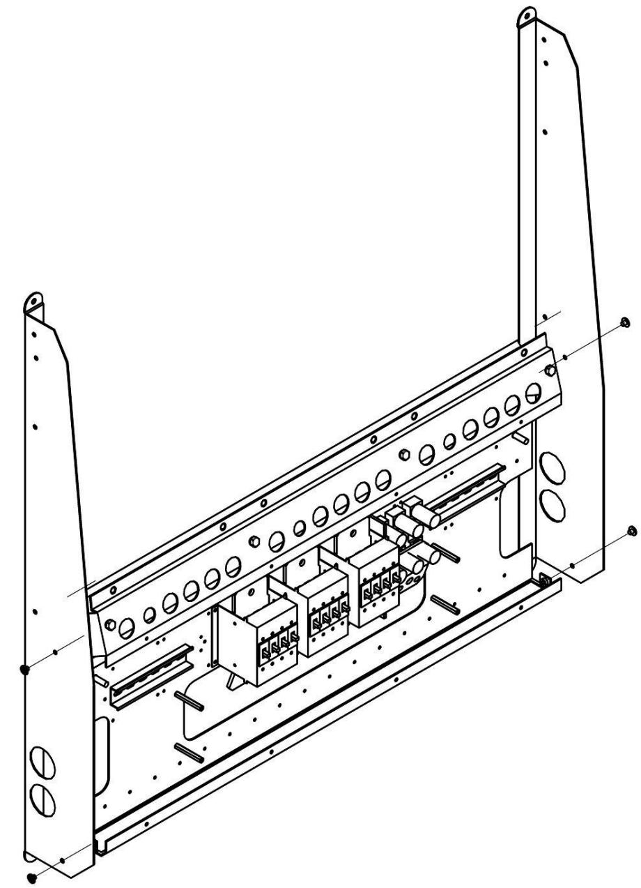
MONTAGE - ASSEMBLY - MONTAGE - MONTAJE (2 / 4)

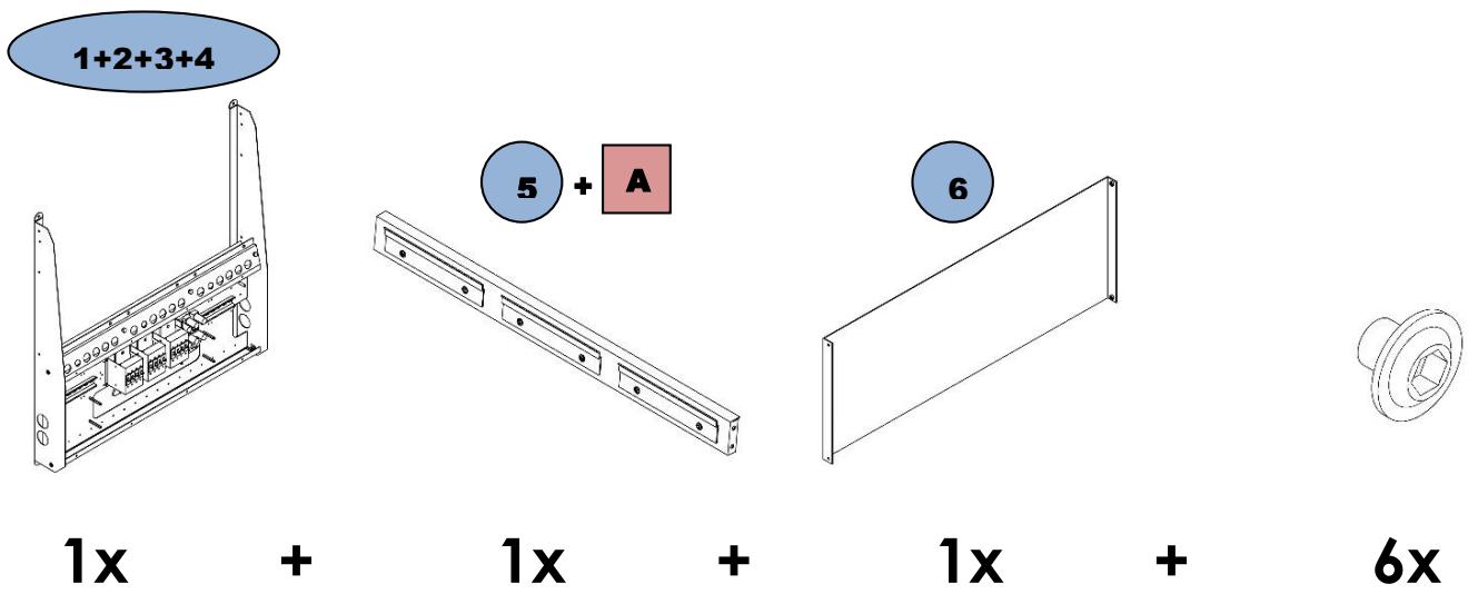
MONTAGE - ASSEMBLY - MONTAGE - MONTAJE (3 / 4)


MONTAGE - ASSEMBLY - MONTAGE - MONTAJE (4 / 4)

PLAN DE PERÇAGE – DRILLING PLAN – BOHR PLAN – PLANO DE PERFORACION

 | A fixer à une paroi solide (béton). Poids d'environ 160Kg !!! |
| To mount on a solid wall (concrete). Approx. weight 160Kg!!! | |
| An genügend feste Wand montieren (z.B. Beton). Gewicht zirka 160Kg !!! | |
| A fijar en una pared sólida (cement). Peso de aproximadamente 160Kg!!! |
MONTAGE XTH – XTH ASSEMBLY – XTH MONTAGE – MONTAJE XTH

1x
+
3x
+
6x

CABLAGE - WIRING - VERKABELUNG - CABLEADO

 | Pour les vis de mis à terre le couple de serrage maximum est de 15Nm. |
| The grounding screws should be tightened with maximum torque of 15 Nm. | |
| Die Erdungsschrauben sollte mit einem maximalen Drehmoment von 15Nm festgezogen werden. | |
| Para el tornillo de puesta a tierra, el par de apriete máximo será de 15Nm. | |
 | Pour le câblage, veuillez-vous référer à l'annexe 1 du manuel de l'Xtender. |
| For the cabling, see Appendix 1 of the Xtender manual. | |
| Für die Verkabelung gehen sie bitte entsprechend dem Anhang 1 der Beschreibung des Xtender vor. | |
| Para el cableado, refiérase al anexo 1 del manual del Xtender. |
FERMETURE - CLOSING - ABDECKUNG - CIERRE


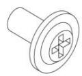
1x + 1x + 1x + 12x

NOTES – NOTES – BERMERKUNGEN - NOTAS

Studer Innotec SA
Rue des Casernes 57
1950 Sion – Switzerland
Tél : +41(0) 27 205 60 80
Fax : +41(0) 27 205 60 88
info@studer-innotec.com
www.studer-innotec.com


- DEUTSCH
- INTRODUCTION
- SUPPLY LIST
- CABLING FLEXIBILITY
- MULTI X-CONNECT SYSTEMS
- VORWORT
- LISTE DES PIÈCES – LIST OF PARTS – STÜCKLISTE – LISTA DE PIEZAS
- MONTAGE - ASSEMBLY - MONTAGE - MONTAJE (1 / 4)
- MONTAGE - ASSEMBLY - MONTAGE - MONTAJE (2 / 4)
- MONTAGE - ASSEMBLY - MONTAGE - MONTAJE (3 / 4)
- MONTAGE - ASSEMBLY - MONTAGE - MONTAJE (4 / 4)
- PLAN DE PERÇAGE – DRILLING PLAN – BOHR PLAN – PLANO DE PERFORACION
- MONTAGE XTH – XTH ASSEMBLY – XTH MONTAGE – MONTAJE XTH
- CABLAGE - WIRING - VERKABELUNG - CABLEADO
- FERMETURE - CLOSING - ABDECKUNG - CIERRE
- NOTES – NOTES – BERMERKUNGEN - NOTAS
Brand : STUDER
Model : X-Connect
Category : Inverter