
B 422X TNG - Electric hedge trimmer PARTNER - Free user manual and instructions
Find the device manual for free B 422X TNG PARTNER in PDF.

| Product type | Electric hedge trimmer |
| Brand | PARTNER |
| Model | B 422X TNG |
| Blade length | 42 cm |
| Tooth spacing | 26 mm |
| Cutting capacity | 20 mm |
| Motor power | 550 W |
| Supply voltage | 230 V ~ 50 Hz |
| Weight | 3.8 kg |
| Sound level (LpA) | 85 dB(A) |
| Vibration level | 2.5 m/s² |
| Cutting type | Double blade |
| Working position | Rear handle rotation 180° |
| Blade protection | Integrated protective housing |
| Safety | Double safety switch with lock |
| Emergency stop | Instantaneous blade brake |
| Maintenance | Cleaning after use, blade lubrication |
| Repairability | Spare parts available (blade, handle, switch) |
| General information | Follow the safety instructions in the manual |
Frequently Asked Questions - B 422X TNG PARTNER
User questions about B 422X TNG PARTNER
0 question about this device. Answer the ones you know or ask your own.
Ask a new question about this device
Download the instructions for your Electric hedge trimmer in PDF format for free! Find your manual B 422X TNG - PARTNER and take your electronic device back in hand. On this page are published all the documents necessary for the use of your device. B 422X TNG by PARTNER.
USER MANUAL B 422X TNG PARTNER
Electrolux Outdoor Products
Via Como 72
23868 Valmadrera (Lecco)
ITALIA
Phone +39 0341 203111 - Fax +39 0341 581671
Our policy of continuous improvement means that the specification of products may be altered from time to time without prior notice.
Electrolux Outdoor Products manufacture products for a number of well known brands under various registered patents, designs and
trademarks in several countries
© Electrolux Outdoor Products Italy

The Electrolux Group. The world's No.1 choice.
The Electrolux Group is the world's largest producer of powered appliances for kitchen, cleaning and outdoor use. More than 55 million
Electrolux Group products (such as refrigerators, cookers, washing machines, vacuum cleaners, chain saws and lawn mowers) are
sold each year to a value of approx. USD 14 billion in more than 150 countries around the world.
PN 249651 REV.01 (12/04)

Electrolux
Electrolux
GB
INSTRUCTION MANUAL
IMPORTANT INFORMATION: Please read these instructions carefully and make sure you understand them before using this unit. Retain these instructions for future reference.
DE
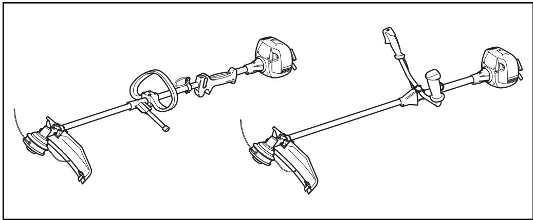
A. General description
1) ENGINE
2) SHAFT
3) THROTTLE TRIGGER
4) REAR CONTROL GRIP
5) BLADE
6) NYLON STRING HEAD
7) STOP SWITCH
8) FUEL ENRICHMENT LEVER
9) STARTER HANDLE
10) HARNESS RING
11) SPARK PLUG
12) AIR FILTER COVER
1) Guaranteed noise level according to directive 2000/14/EC
2) Manufacturer's name and address
3) Year of manufacture (last two figures; e.g. 03=2003)
7) CE seal of conformity
B. Safety precautions
Explanation of Symbols

Warning

Safety apparel: Approved protective goggles or visor, approved hard hat and hearing protection.

Read the instructions for the user carefully and make sure you understand how all the controls work.

Safety apparel: Approved gloves.

Safety apparel: Approved boots.

Do not smoke when refueling or using the machine.

Fuel enrichment (starting aid).

Danger of flying debris.

Minimum safety distance 15m.

Emergency stop.

Maximum shaft speed.

Danger of kickback. The blade is capable of amputating arms and legs.

CAUTION! Danger of serious leg injuries. Take scrupulous care to follow the instructions in the manual.

CAUTION! The cutting parts and muffler may get very hot and cause burns. Wait a w minutes before touching them.
Use of the manual
- Anyone who uses the machine should have read the entire manual with extreme care.
- All users should be familiar with the operations for use of the machine under absolutely safe conditions as described in this manual, and should be instructed in the proper cutting techniques to use, possibly by practical demonstration.
- Do not allow children or persons who are not familiar with these instructions and are not sufficiently trained to use the brush cutter. Local regulations may specify an age limit for users.
- Keep this manual with the machine when selling or lending it, to enable the future users to familiarize themselves with the product and instructions for safe use.
- All parts of the manual are equally important for the purpose of preventing injury to the operator or damage to the machine. To facilitate your reading, section B is divided into parts that can be called up in the rest of the manual, marked with the "CAUTION" symbol followed by the number of the corresponding paragraph, to concentrate your attention on the main safety procedures related to a particular situation.
Prior to use
- Respect of the procedures described in this manual does not eliminate the risks of accidents but does reduce the probability of their occurring or the effect of the damage.
- If you have never used a brush cutter before, practice using it for a while before actually starting to work with it.
- The operator or user is responsible for any damages to third parties or their property, and for any dangers to which they may be subject.
- Do not use this machine for any other purpose than that for which it was designed, using the proper cutting devices as indicated in the instructions.
- Do not use the machine if you are tired, in poor health or under the effects of alcohol or medication that could affect your reactions.
- Make sure you know how to stop the engine and blade if necessary (see section entitled "Starting and stopping the engine").
Inspect the machine carefully before every use, in case of violent impact or signs of malfunction.
Make sure the machine is correctly assembled, and all its parts are working properly. Make sure the screws are all in place and securely tightened. Check operation of the accelerator control block and make sure there is no leakage of fuel. Check that the cutting tool does not move with the motor running at idle speed. Make sure the transmission pipe is properly fastened to the motor joint and the line cutter head or blade are correctly fastened with the screw fastening the blade fully tightened.
2 Replace any accessories (blades, nylon string heads, guards) which show damage or cracks or appear excessively worn. Have your Authorized Service Center replace any damaged parts. For nylon string heads, use only strings made of flexible material recommended by the manufacturer. For example, you should never use metal wire because it could cause serious injuries to people, property and animals. An unsuitable string could break and turn into a very dangerous missile. In mounting the cutting utensils follow the instructions in the chapter entitled "Usable cutting tools and their installation on the machine". ABSOLUTELY DO NOT USE THE BRUSH CUTTER IF THE SPECIFIC SAFETY GUARD FOR THE CUTTING DEVICE IN USE IS NOT SECURELY FASTENED (see chapter "Assembly/disassembly"). Failure to follow this rule can expose you to serious danger such as:
- possible contact with rotating and cutting parts;
- possible contact with flying debris.
Never use a brush cutter without its safety pole guard correctly in place. Only use blades or nylon string heads clearly marked with a maximum speed of at least 10,500 min-1.
IF A METAL 24-80 TOOTH BLADE (A SAW TOOTH BLADE) IS USED A DOUBLE SHOULDER HARNES AND A SAFETY GUARD (PROTECTION) MUST ALSO BE USED AS MARKED IN THE SUMMARY CHART
3 Use only original or approved accessories and spare parts, which you can purchase from our official distributors. The use of other accessories and spare parts increases the danger of injury and in this case the manufacturer has no liability for damage to persons or property. Never attempt to use the machine if it is incom
plete, defective or has been altered by anyone other than an Authorized Service Center. The risk of accidents increases considerably if maintenance is not carried our regularly in a professional way. In case of doubt contact an authorized service center.
4 All operations of maintenance, assembly, disassembly and fueling should be done with the machine on a flat, solid surface so that the motor cannot turn over, in a stable position with the motor off, the switch turned to O/STOP, the cutting tool stopped and wearing adequate protective gloves.
Apparel
5 Dress suitably for the job; wear approved personal protection gear:
- Closely fitting protective clothing (do not wear shorts or loose clothing). Do not wear jewelry that could get caught in moving parts of the machine.
- Safety boots with non-slip sole, crush-resistant toe cap and protection against cuts (do not wear sandals or work barefoot).
- Sturdy gloves resistant to cuts and vibrations.
- Safety visor or protective goggles. Remove the protective film if any.
- Hearing protection.
- Hard hat (if there is any risk of falling objects).
Health precautions
6 Avoid prolonged use. Noise and vibrations may be dangerous. Prolonged use of the machine or other equipment expose the operator to vibrations that can cause the White Finger Syndrome (Syndrome of Raynaud). This could reduce the sensitivity of the hands in distinguishing different temperatures and cause a general numbness. The operator should therefore check the conditions of the hands and fingers if the machine is used continuously or regularly. If one of the symptoms should appear, consult a doctor immediately. Prolonged use of the machine or other equipment can cause discomfort, stress, fatigue, hearing damage. Wear suitable hearing protection when using the machine. Correct and scrupulous maintenance can also help to protect you further from the risk of noise and vibration.
7 Avoid contact of the eyes and skin with any oil or fuel. Do not inhale the gasoline fumes as they are toxic. Do not start or run the motor in closed or poorly ventilated places. The exhaust fumes are poisonous to breathe and can be asphyxiating and even fatal.
Work zone
8 Examine the work area and be careful of any hazards (such as roads, driveways, power lines, hanging tree limbs, etc.). Take special care when working on sloping terrain. Before use, remove any rubbish from the work area such as rocks, broken glass, ropes, metal parts, cans, bottles and any foreign body that could become entangled with rotating parts or be projected dangerously at a distance. Take account of possible hazards that may not be perceived because of the noise of the machine. Make sure there is someone in the vicinity within safe calling distance in case of accident.
During use
9 During use and for a few minutes after switching off the machine, the gearbox and zone near the shaft on which the cutting device is fastened are very hot. The muffler and its guard are very hot during use and after the engine has been switched off, even with the engine running at minimum speed. Contact can cause burns. Do not touch these parts if they are still hot.
Twigs or grass may jam between the safety guard and the blade or nylon string head. Never try to remove this material with the engine running and the blade rotating. Watch out for the rotating parts and hot surfaces of the machine. Contact between the blades and any extraneous objects could cause serious injury to the operator or other people or animals in the vicinity, and could also damage the machine. Cut only the material recommended for each accessory and take care not to let the blades come into contact with rocks, metal parts, etc. The blade is sharp, so be very careful when handling it even with the engine off.
11 Keep any other persons or animals away from the work zone (minimum distance 15 meters). Since there is a danger when you are working that the blade or nylon string head could throw out grass, dirt, rocks or foreign bodies, when someone approaches switch the engine off or stop the blade or rotating head (see section entitled "Starting and stopping the engine"). Fasten your hair above shoulder length. Start the machine in a flat place, in a stable position, making sure the cutting tool does not touch any obstacles. Use the machine holding it to the right of your body so that the exhaust fumes can escape freely without obstruction from your clothing. While working, grip the brush cutter firmly with both hands. Stand in a stable position on your feet. Keep the grips clean and dry. Do not use the brush cutter while standing on a ladder or other unstable support. You should always be able to control your balance. Never use the machine under extreme weather conditions or in bad weather (very low temperatures, very hot, humid climate, fog, rain, wind, etc.). Keep all parts of your body and clothing away from the blades during startup or when the engine is running. During use, keep the work zone in front of you. Never cut walking backwards as you cannot see possible hazards. Do not put the machine down with the engine running. Never leave the machine alone. Never raise the brush cutter above knee level during cutting.
12 Adjust the shaft fastening buckle so that the blade or line cutter head are parallel to the ground. The connection point should be held in the original position so as to avoid unbalancing the shaft.
Precautions for carrying the machine
13 Never carry the brush cutter, even for short distances, with the engine running. Switch off the engine and carry it with the blade or nylon string head facing backward. For your safety, during transport and storage, always protect the blade with the guard supplied with the machine (see "Protection for transport"). When you transport the brush cutter in a motor vehicle, place it in a stable fixed position so that no fuel leaks out. We
recommend emptying the fuel tank whenever you transport the machine.
Fire prevention precautions
14 Never work with the brush cutter in the presence of fire or spilled gasoline. If you have spilt it on yourself, change your clothes at once. Keep the machine clean by removing any grass cuttings, leaves, excess oil to reduce the fire hazard. Engine exhaust fumes can get very hot and may contain sparks. Do not use the machine near inflammable material. The muffler gets very hot during use and remains hot for some time after switching off the engine. This also applies at idle speed. Take every precaution to reduce the fire hazard, especially in the presence of inflammable materials or gas. Start the engine at a distance from the filling site and far away from any fuel tanks (at least 3 meters).
15 When filling the fuel tank, dry any spilled fuel. Never add fuel in the tank when the engine is running or hot to avoid the risk of fire (let the engine cool off before filling the tank). Fill the tank outdoor, far from flames or sparks. Do not take the cap off the tank with the engine running. Open the cap on the tank carefully to eliminate
any excess pressure. After fueling, close the cap tightly. Take care not to spill any fuel. The fumes produced by the fuel can cause an explosion or fire. Gasoline is highly inflammable: before going near any type of fuel, put out your cigarette, pipe or cigar. Do not smoke or take sources of heat or sparks near the fuel. Never refuel near or over inflammable objects (dry leaves, etc.).
Kickback
16 Machines equipped with blades may produce a violent kickback on contact with solid bodies. The force of the kickback can cause the operator to lose control of the machine. The blade is capable of amputating arms and legs. Always work with a sharp blade. A blade with worn teeth can create problems in cutting and can cause KICKBACK, that is, a violent thrust on the front of the machine caused by the impact of the blade against wood or solid foreign bodies. This kickback can cause loss of control of the machine. Never sharpen a damaged blade: replace with a new one. Kickback can also occur when cutting with any type of blade in the hazardous zone (see 13). Do not let the blade cut in the risk sector to prevent kickback.
C. Description of the safety devices on the machine


Safety lever

Never use the machine with its Safety lever pressed with adhesive tape, string or other.
This device serves to prevent accidentally pressing the throttle trigger (fig. A no. 3). In fact, the trigger (fig. A no. 3), can only be pressed if the safety lever is pressed at the same time (fig. A no. 17). By means of 2 separate springs, upon releasing the grip, the throttle trigger (fig. A no. 3) and safety lever (fig. A no. 17) return automatically to their original positions.
Antivibration device
The machine is equipped with an antivibration device which serves to reduce the vibrations transmitted to the operator.
Engine stop device
Turn the stop button Stop (fig. A no. 7) to O / STOP to stop the engine. To make sure this button works properly, start the engine and check that it stops when the Stop button is turned to the Stop position.
Protection for transport


Never use a machine with the blade cover still on.
ENGLISH - 4
The guard covers the sharp extremities of the blade when the machine is in the resting position for transport or storage.
Safety guard


This very important safety device (fig. A no.19) prevents any objects that come into contact with the cutting device, or the grass itself, from flying up and striking the operator.
Safety pole guard


This device, fastened to the machine, ensures a minimum distance between the operator and the cutting device during use, and prevents the machine from striking and injuring the operator if the blade hits a hard surface (fig. A no. 18).
Muffler


The muffler serves to reduce the noise level to a minimum and to route the exhaust fumes produced by the combustion engine away from the operator.
Harness

CAUTION! It is very important to familiarize yourself with the release mecha
D. Fuel Mixture
Preparation of the mixture


Do not use any other type of fuel than the type recommended in this manual. This machine is equipped with a two-stroke engine and should therefore be fueled with a mixture of unleaded gasoline (with a minimum octane rating = 90 ) and fully synthetic oil specific for two-speed engines that use unleaded gasoline in the proportions indicated in the table on the cover, fig. D.
Control the specifications of the oil shown on the package; the use of oil lacking the specifications expressly indicated in this manual could cause serious damage to the engine!
To obtain the best mixture, pour the oil into an approved container first, followed by the gasoline, and shake the container well (every time you take fuel out of it).
The characteristics of the mixture tend to deteriorate in time, so you should only prepare as much mixture as you are going to need (the use of deteriorated fuel can seriously damage the engine).
Filling the tank


Clean the area around the fuel cap before removing it, to prevent any impurities from contaminating the fuel. Take the cap off the fuel container carefully. Unscrew the cap on the fuel tank and fill it with the necessary quality, using a funnel.
During use, to prevent problems in starting the engine again, we strongly recommend that you avoid letting the fuel run out in the tank.
Fuel storage


Store the fuel in a cool, well-ventilated place, in an approved fuel storage container.
Never store the engine with fuel in the tank in a poorly ventilated place where the fumes produced by the gasoline could propagate and reach a fire, candle, burner or furnace pilot light, water heater, dryer, etc. Never store excessive quantities of fuel.
E. Assembly/disassembly
E1. Delta grip


For your safety, fasten the delta handle in front of the label placed on the shaft at a distance of at least 11 cm from the rear grip. The handle should be fastened in a comfortable working position. If you are using sawtooth blades, the grip distance should be moved by at least 36 cm. The safety pole guard should be mounted using the accessories supplied and in the configuration shown in the figure,in contact with the delta handle.
E2. Double handled grip (A)
The grip (A) can be adjusted to suit the needs of the operator by moving it forward or backward. Loosen the knob, place the handle in the desired position then tighten the knob again.
CAUTION! The handle assembly (A) can be folded parallel to the transmission shaft to facilitate transport and storage of the machine. Loosen the knob, turn the support, by 90^ clockwise, fold the handle (A) in the desired position and tighten the knob.
E3. Double Handle (B)
Adjust and secure double hand clamp by tightening the screws.
E4. Fitting guard on line cutter head and grass cutting blade


Fit the safety guard (A) against the gearbox (I) position the lower clamp (G) in the housing under the shield and the upper clamp (F) over the shaft. Insert and tighten the screws (H).
Safety guard extension (exclusively for use with nylon string head)
The string cutting blade housed in the plastic shield will cut the nylon string to optimum length; a string that is too long reduces the rotation speed of the engine and interferes with cutting efficiency, as well as increasing the risk of injury.
The extension (B) should be installed only for use with the nylon string head, with the aid of the string cutter blade (L), that regulates the length of the string and thus the cutting diameter. For correct assembly see the illustration on the cover and perform the following sequence of steps: Insert the extension (B) on the safety guard (A) at the reference notches (C), and fasten with the screws (D), then apply the string cutter blade (L) and fasten it with the screw (E) (Make sure the screws are tightened all the way (E) and are not loosened by the vibrations. If necessary, tighten them again).
E5. Assembly/disassembly of line cutter head


Apply the nylon string head as shown in the illustration: 1) Protection flange 2) Upper plate 3) Protection (nylon string head B) 4) Nylon string head. Tighten by turning counterclockwise. As you tighten, hold the nylon string head and plate still and insert the wrench or screwdriver supplied in the holes in the plate and gearbox; first turn the plate until the two holes match.
E6. Assembly/disassembly of grass cutter blade


Do not use the nylon string head guard extension (H) with metal blades.
Assemble blade as illustrated: a) Flange guard - b) Upper cap with blade centering - c) Blade with text and directional arrow facing upwards - d) Lower washer - e) Fixed mower gauge - f) Blade locking screw (length mm 16). If you want to assemble the rotating mower gauge, proceed as illustrated: a) Flange guard - b) Upper cap with blade centering - c) Blade with text and directional arrow facing upwards - d) Lower washer - e) Spacer - f) Rotating mower gauge - g) Blade locking screw (length mm 34,5).
Assembly of sawtooth blade and blade guard


When using the sawtooth blade, remove the guard for the line cutter head and grass cutblade and replace the flange guard (A) with sawtooth blade guard (H).

- Saw tooth blades (24 - 80 tooth) have a central base diameter of 20mm and there require the use of the appropriate size top to ensure a correct fit. The part number is used in the cutting attachment summary chart.
For assembly see figures (E7, E8).
F. Starting and stopping the engine


CAUTION! Start the brush cutter in a flat place. During startup stand in a stable position. Make sure the blade or nylon string head do not touch the ground or any obstacles.
CAUTION! Grip the knob of the starter with one hand and hold the machine in a stable position with the other. (Take care not to wind the starter string around your hand) and pull slowly until you encounter some resistance, then pull the cord sharply and forcefully (to start the engine when Do not pull the starter cord all the way and do not release it abruptly against the machine as this could damage it.
Startup of cold engine
F1. Stop switch (A) turned to "I" opposite the "STOP" mark.
F2. Turn the fuel enrichment lever (B) to the closed position.
F3. Press the air purge diaphragm repeatedly until fuel begins to fill the diaphragm (C). The diaphragm need not be completely filled. Push the decompression valve (D) down if your models is fitted with one. Pull the cord until the engine starts. Let the motor run for a few seconds and accelerate. This will automatically return the fuel enrichment lever to its original position.

The cutting devices are now rotating.
Startup of warm engine
F1. STOP switch turned to "I" (START). Throttle trigger lever in minimum position (released). Enrichment lever (B) in original position.
F3. Repeat item F3 in the previous paragraph. Stopping the engine
F5. Turn the stop switch to "O" (STOP).
G. Carburetor adjustment
8 9 10 11
Your machine can be equipped with a low emission carburetor. We recommend that you have any adjustment of the carburetor made exclusively by an authorized service center, which disposes of special equipment for ensuring the best performance with the lowest emissions. To adjust the speed to the minimum, turn the screw marked (T) as shown: With the engine running and well warmed up, turn the screw (T) gently clockwise, until the engine rotates at regular speed (stead noise), without the cutting devices in motion. If
the cutting devices are moving, turn the screw (T) gently counterclockwise until you obtain the proper adjustment. The correct minimum speed is shown in the instruction manual in the paragraph of technical data.
All the above adjustments should be made with the cutting devices correctly installed.
The warranty may be invalidated due to erroneous adjustments made by personnel not belonging to authorized service centers.
H. Routine maintenance
1 2 3 4 7 9 10
H1. After every use
In order to avoid overheating the motor, remove any dust and dirt from the slots on the cylinder cover and finds of the cylinder using a wooden scraper. Store the machine in a dry place.
After 25 hours of use
Remove the filter as shown in the figure and clean it using a gentle jet of compressed air. For more thorough cleansing, you can wash it with soapy water.
After 50 hours of use
Add some high speed gear grease in the gearbox through hole (C). Remove and clean the spark plug (set the space between the electrode at 0.5 / 0.6 ~mm ). Replace if excessively encrusted. In case of excessive encrustation check the carburetor adjustment, the percentage of oil in the fuel mixture and make sure the oil is of excellent quality and suitable for two-stroke engines.
After 100 hours of use
Replace the spark plug.
Every three months
Contact your Service Center for a complete overhaul, replacement of the fuel filter and cleaning of the parts inside the machine. This will reduce the possibility of unexpected problems and will ensure the good performance and long life of your machine.
Periods of prolonged disuse
See "Environmental information".
If you use the machine in an exceptionally dirty or dusty environment these operations should be carried out more often.
H2. Replacement of nylon string (A)
To replace the reel of string, press both the release paws indicated by the arrows, remove the empty reel, unroll any string left and rewind the new string. Open the original package of string and insert the ends of the two strings in the eyelets on the reel, then wind the strings completely on the reel in the same direction and fasten the end of each string in the 2 opposite grooves. Replace the reel in its housing and thread the ends of the strings in their bushings. Pull each string so that about 15cm comes out on each side. Reassemble the nylon string head as shown (fig. H5). If the reel becomes excessively worn, replace it with a whole new reel.
H3. Replacement of nylon string (B)
1) Loosen the locking nut on the base of the nylon head by turning it clockwise.
2) Remove the base cover assembly. Remove the empty spool from the housing and discard any remaining line.
3) Prepare 2 lengths (8ft each) of 2.4mm nylon line. Thread 1 end of each line into the two holes on opposite sides of the spool. Pinch the exposed ends flat with a pair of pliers to prevent them slipping through the hole.
4) Wind the two lines in the same direction around the spool.
5) Slide the end of the two lines into the grooves to hold the line temporarily.
6) Position the spool back into the housing and pull the line through the eyelets.
7) Pull about 15cm (5ins) of line out on either side.
8) Reassemble the nylon string head as illustrated; mower gauge, spring and locking nut (tighten in an anti-clockwise direction).


Cutting techniques
During the cutting operations, keep the engine running at high speed. After every cutting stage, decelerate the engine to minimum speed as running it at top speed without a load can damage the engine severely.

Wait until the engine is running at minimum speed before moving the machine from one section to another.
The machine is ideal to complete the work of the lawnmover. In fact, it can reach places where a normal lawnmower is unable to go.
Cutting and trimming grass borders with the nylon string head
Cutting with the nylon string head is suitable for light jobs like trimming borders and cutting the grass around trees.
Mowing
To prevent damage to your lawn or the cutting mechanism, keep the string parallel to the ground but avoid contact with the terrain.
Trimming borders
Angle the nylon string head keeping it a short distance from the ground. Cut using the end of the string. Do not press the string against the material to be cut.
11. Drawing out the string (A)
During cutting, the nylon string wears naturally causing an increase in the speed of the engine and a reduced cutting capacity. When this happens, to bring out more string bump the head against the ground: release the throttle trigger to reduce the engine speed to less than 8000 rpm.
Tap gently on the ground with the button (A) as shown in the figure and the string will come out automatically. Accelerate again. If the string does not come out make sure there is still some left and try again.
I2. Drawing out the string (B)
In order to extend the nylon line as it wears down, pull the mower gauge downwards and turn it in a clockwise direction to feed out the desired length of line.
I3. Thinning grass with the grass cutter blade

The grass is cut with swinging motions from side to side, maintaining the blade parallel to the ground. During the right to left swing the grass is cut, while the backswing must be made without using the blade.
KICKBACK can occur when cutting is done with the risk sector of the blade; we recommend cutting with the rest of the blade. Take care that the cup supporting the blade just grazes the ground.
This will prevent the blade from touching the ground.
Use of sawtooth blade

Do not attempt to cut trees with a larger than recommended diameter, to prevent the risk of kickback or damage to the blade.
The sawtooth blade serves to cut bushes and small trees, with maximum diameter of seven centimeters. Rest the left side of the special shield on the trunk while cutting to limit the risk of losing control of the machine.
L. Environmental information
This section contains information useful for maintaining the characteristics of eco-compatibility included in the origin design of the machine, and as regards proper use and disposal of oil and fuel.
Design
In the design stage, care was taken to develop an engine with reduced consumption and low emissions of noise and pollutant exhaust fumes.
Use of machine
The operations of filling the tank with the fuel mix
ture should be carried out in such a way as to avoid spilling fuel and contaminating the soil and environment.
Periods of prolonged disuse
Always empty the fuel tank with the same precautions used in filling it.
Disposal
Do not dispose inappropriately of the machine when it is no longer usable. Deliver it to an authorized organization for proper disposal in compliance with the regulations in force.
M. Troubleshooting table
| Engine will not start | Engine runs badly or looses power when cutting | The machine runs but does not cut well | |
| Check STOP switch is in the position I. | ● | ||
| Control fuel level min. 25% tank capacity. | ● | ● | |
| Check air filter is clean. | ● | ● | |
| Remove spark plug, dry it, clean it and adjust it, and replace it, if necessary. | ● | ● | |
| Change fuel filter. Contact your dealer. | ● | ||
| Carefully follow the cutting accessory assembly instructions. | ● | ||
| Check metal cutting accessory is sharp. Otherwise, contact your dealer. | ● |
The engine continues to have problems: contact your authorized supplier
The undersigned, authorized by Electrolux Outdoor Products Italy S.P.A., declares that the following products model /TYPE: BC010A, BC010B starting from the serial numbers produced from 2003 on, manufactured by Electrolux Outdoor Products Italy S.P.A., Valmadrera, Italia, comply with European Directive: 98/37/EEC (Machine Directive), 93/68/EEC (EEC Marking Directive) & 89/336/EEC (Electromagnetic Compatibility Directive), directive 2000/14/EEC (Enclosure V).

Valmadrera, 15.12.03
Giuseppe Todero (Technical Manager)
Electrolux Outdoor Products Italy S.P.A.
Via Como 72, 23868 Valmadrera (Lecco) ITALY
O. Technical data
| Displacement (cm3) | 34 | 36 | 38 | 42 | 46 |
| Bore (mm) | 38 | 40 | 40 | 41 | 43 |
| Stroke (mm) | 30 | 30 | 30 | 30 | 30 |
| Engine output (kW) (ISO 8893) | 1,2 | 1,25 | 1,3 | 1,6 | 1,8 |
| Maximum shaft rotation frequency (min-1) | 7.700 | 7.700 | 7.700 | 7.700 | 7.700 |
| Rotation speed (frequency of rotation) of engine at maximum rotation frequency recommended for shaft (min-1) | 12.100 | 12.100 | 12.100 | 12.100 | 12.100 |
| Engine speed at max power (min-1) | 8.000 | 8.000 | 8.000 | 8.000 | 8.200 |
| Minimum speed (min-1) | 2.800 | 2.800 | 2.800 | 2.800 | 2.800 |
| Maximum speed, no load (min-1) | 10.000 | 10.000 | 10.000 | 10.000 | 10.000 |
| Dry weight (kg) | 7,1 | 7,3 | 7,3-8,3PRO | 7,3-8,4PRO | 7,7-8,7PRO |
| Fuel tank capacity (cm3) | 900 | 900 | 900 | 900 | 900 |
| Blade locking nut tightening torque (Nm) | 17 | 17 | 17 | 17 | 17 |
| Noise pressure (at operator ear) Lpav (dBA) (ISO 7917) | 97 | 97 | 97 | 97 | 97 |
| Measured sound power level Lwav (dBA) (ISO 10884) | 113 | 113 | 113 | 113 | 113 |
| Guaranteed noise level Lwav (dBA) (ISO 10884) | 114 | 114 | 114 | 114 | 114 |
| Vibrations level string head (ISO 7916) (m/s2) max-min | 8,2-1,6 | 8,2-1,7 | 8,2-1,7 | 10,55-1,8 | 12,5-1,06 |
| Vibrations level blade (ISO 7916) (m/s2) max-min | 8,2-1,6 | 8,2-1,7 | 8,2-1,7 | 16,38-1,8 | 17,79-1,06 |