
D4N-R - Limit switches OMRON - Free user manual and instructions
Find the device manual for free D4N-R OMRON in PDF.


| Product type | Positive break safety limit switch |
| Brand | OMRON |
| Model | D4N-R |
| Contact configuration | 1 NC + 1 NO (positive break) |
| Rated voltage | 250 V AC / 30 V DC |
| Rated current | 5 A (AC), 3 A (DC) |
| Protection rating | IP67 (temporary immersion) |
| Housing material | Impact-resistant reinforced plastic |
| Actuator type | Horizontal lever roller |
| Actuator travel | 15 mm |
| Actuation force | 5 N (minimum) |
| Operating temperature | -20 °C to +70 °C |
| Mechanical life | 10 million operations |
| Electrical life | 500,000 operations (under rated load) |
| Dimensions (L x W x H) | 75 x 30 x 30 mm |
| Weight | 60 g |
| Main functions | Limit detection, safety by positive break of NC contacts, emergency stop |
| Maintenance and cleaning | Clean with a dry or slightly damp cloth (no solvent). Check actuator and contact wear regularly. |
| Safety | NC contact with positive break compliant with safety standards (EN 60947-5-1). Double insulation. |
| Spare parts and repairability | Actuator and contacts replaceable. Parts available through OMRON network. |
| General information | CE, UL, CSA certifications. Use in industrial machinery, conveyors, automatic doors. |
Frequently Asked Questions - D4N-R OMRON
User questions about D4N-R OMRON
0 question about this device. Answer the ones you know or ask your own.
Ask a new question about this device
Download the instructions for your Limit switches in PDF format for free! Find your manual D4N-R - OMRON and take your electronic device back in hand. On this page are published all the documents necessary for the use of your device. D4N-R by OMRON.
USER MANUAL D4N-R OMRON
New Series of manual-reset Limit Switch
- Lineup includes three contact models with 2NC/1NO and 3NC contacts in addition to the 1NC/ 1NO, and 2NC version. Version with MBB contacts meet applications for avanced requirements.
- M12-connector models are available, saving on labor and simplifying maintenance.
- Standardized gold-clad contacts provide high contact reliability. Can be used with both standard loads and microloads.
- Free of lead, cadmium, and hexavalent chrome, reducing the burden on the environment.
- Conforms to EN115 and EN81-1.
Be sure to read the "Safety Precautions" on page G-277.
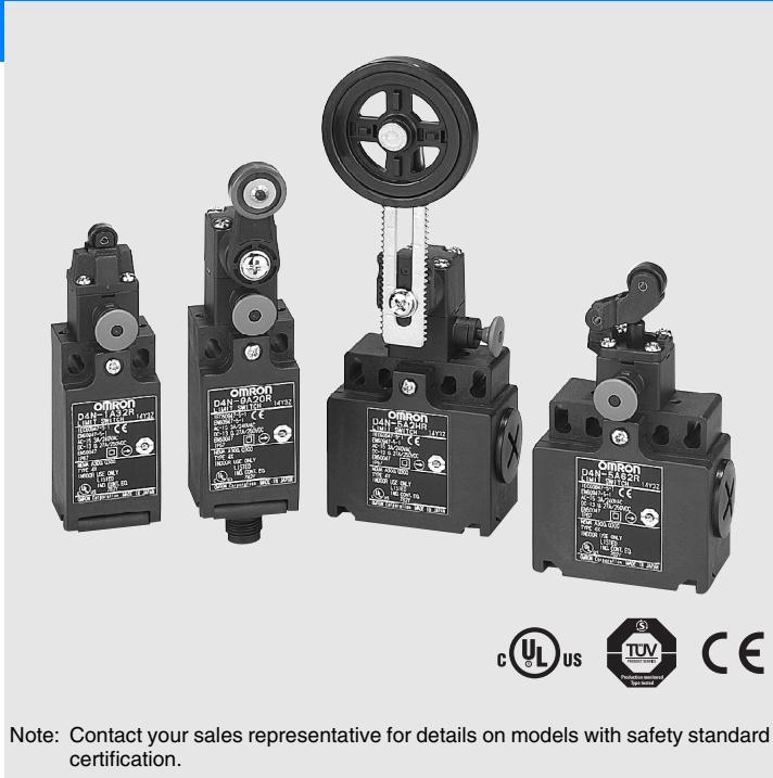
Model Number Structure
D4N-□□□R
123
1. Conduit/Connector size
1:Pg13.5 (1-conduit)
2: G1/2 (1-conduit)
3: 1/2-14NPT (1-conduit)
4: M20 (1-conduit)
5:Pg13.5 (2-conduit)
6: G1/2 (2-conduit)
7: 1/2-14NPT (M20 2-conduit with 1/2-14NPT changing adaptor included)
8: M20 (2-conduit)
9: M12 connector (1-conduit)
2. Built-in Switch
A: 1NC/1NO (slow-action)
B: 2NC (slow-action)
C: 2NC/1NO (slow-action)
D: 3NC (slow-action)
3. Head and Actuator
20:Roller lever (resin lever, resin roller)
2G:Adjustable roller lever, form lock (metal lever, resin roller)
2H:Adjustable roller lever, form lock (metal lever. rubber roller)
31:Top plunger
32:Top roller plunger
62:One-way roller arm lever (horizontal)
72:One-way roller arm lever (vertical)
List of Models
| Actuator | Conduit size | Built-in switch mechanism | ||||
| 1NC/1NO(Slow-action) | 2NC(Slow-action) | 2NC/1NO(Slow-action) | 3NC(Slow-action) | |||
| Roller lever(resin lever, resin roller) | 1-conduit | Pg13.5 | D4N-1A20R | D4N-1B20R | D4N-1C20R | D4N-1D20R |
| G1/2 | D4N-2A20R | D4N-2B20R | D4N-2C20R | D4N-2D20R | ||
| 1/2-14NPT | D4N-3A20R | D4N-3B20R | D4N-3C20R | D4N-3D20R | ||
| M20 | D4N-4A20R | D4N-4B20R | D4N-4C20R | D4N-4D20R | ||
| M12 connector | D4N-9A20R | D4N-9B20R | --- | --- | ||
| 2-conduit | Pg13.5 | D4N-5A20R | D4N-5B20R | D4N-5C20R | D4N-5D20R | |
| G1/2 | D4N-6A20R | D4N-6B20R | D4N-6C20R | D4N-6D20R | ||
| 1/2-14NPT(See note 2.) | D4N-7A20R | D4N-7B20R | D4N-7C20R | D4N-7D20R | ||
| M20 | D4N-8A20R | D4N-8B20R | D4N-8C20R | D4N-8D20R | ||
| Adjustable roller lever, form lock(metal lever, resin roller) | 1-conduit | Pg13.5 | D4N-1A2GR | D4N-1B2GR | D4N-1C2GR | D4N-1D2GR |
| G1/2 | D4N-2A2GR | D4N-2B2GR | D4N-2C2GR | D4N-2D2GR | ||
| 1/2-14NPT | D4N-3A2GR | D4N-3B2GR | D4N-3C2GR | D4N-3D2GR | ||
| M20 | D4N-4A2GR | D4N-4B2GR | D4N-4C2GR | D4N-4D2GR | ||
| M12 connector | D4N-9A2GR | D4N-9B2GR | --- | --- | ||
| 2-conduit | Pg13.5 | D4N-5A2GR | D4N-5B2GR | D4N-5C2GR | D4N-5D2GR | |
| G1/2 | D4N-6A2GR | D4N-6B2GR | D4N-6C2GR | D4N-6D2GR | ||
| 1/2-14NPT(See note 2.) | D4N-7A2GR | D4N-7B2GR | D4N-7C2GR | D4N-7D2GR | ||
| M20 | D4N-8A2GR | D4N-8B2GR | D4N-8C2GR | D4N-8D2GR | ||
| Adjustable roller lever, form lock(metal lever, rubber roller) | 1-conduit | Pg13.5 | D4N-1A2HR | D4N-1B2HR | D4N-1C2HR | D4N-1D2HR |
| G1/2 | D4N-2A2HR | D4N-2B2HR | D4N-2C2HR | D4N-2D2HR | ||
| 1/2-14NPT | D4N-3A2HR | D4N-3B2HR | D4N-3C2HR | D4N-3D2HR | ||
| M20 | D4N-4A2HR | D4N-4B2HR | D4N-4C2HR | D4N-4D2HR | ||
| M12 connector | D4N-9A2HR | D4N-9B2HR | --- | --- | ||
| 2-conduit | Pg13.5 | D4N-5A2HR | D4N-5B2HR | D4N-5C2HR | D4N-5D2HR | |
| G1/2 | D4N-6A2HR | D4N-6B2HR | D4N-6C2HR | D4N-6D2HR | ||
| 1/2-14NPT(See note 2.) | D4N-7A2HR | D4N-7B2HR | D4N-7C2HR | D4N-7D2HR | ||
| M20 | D4N-8A2HR | D4N-8B2HR | D4N-8C2HR | D4N-8D2HR | ||
| Plunger | 1-conduit | Pg13.5 | D4N-1A31R | D4N-1B31R | D4N-1C31R | D4N-1D31R |
| G1/2 | D4N-2A31R | D4N-2B31R | D4N-2C31R | D4N-2D31R | ||
| 1/2-14NPT | D4N-3A31R | D4N-3B31R | D4N-3C31R | D4N-3D31R | ||
| M20 | D4N-4A31R | D4N-4B31R | D4N-4C31R | D4N-4D31R | ||
| M12 connector | D4N-9A31R | D4N-9B31R | --- | --- | ||
| 2-conduit | Pg13.5 | D4N-5A31R | D4N-5B31R | D4N-5C31R | D4N-5D31R | |
| G1/2 | D4N-6A31R | D4N-6B31R | D4N-6C31R | D4N-6D31R | ||
| 1/2-14NPT(See note 2.) | D4N-7A31R | D4N-7B31R | D4N-7C31R | D4N-7D31R | ||
| M20 | D4N-8A31R | D4N-8B31R | D4N-8C31R | D4N-8D31R | ||
| Roller plunger | 1-conduit | Pg13.5 | D4N-1A32R | D4N-1B32R | D4N-1C32R | D4N-1D32R |
| G1/2 | D4N-2A32R | D4N-2B32R | D4N-2C32R | D4N-2D32R | ||
| 1/2-14NPT | D4N-3A32R | D4N-3B32R | D4N-3C32R | D4N-3D32R | ||
| M20 | D4N-4A32R | D4N-4B32R | D4N-4C32R | D4N-4D32R | ||
| M12 connector | D4N-9A32R | D4N-9B32R | --- | --- | ||
| 2-conduit | Pg13.5 | D4N-5A32R | D4N-5B32R | D4N-5C32R | D4N-5D32R | |
| G1/2 | D4N-6A32R | D4N-6B32R | D4N-6C32R | D4N-6D32R | ||
| 1/2-14NPT(See note 2.) | D4N-7A32R | D4N-7B32R | D4N-7C32R | D4N-7D32R | ||
| M20 | D4N-8A32R | D4N-8B32R | D4N-8C32R | D4N-8D32R | ||
Preferred types
| Actuator | Conduit size | Built-in switch mechanism | ||||
| 1NC/1NO(Slow-action) | 2NC(Slow-action) | 2NC/1NO(Slow-action) | 3NC(Slow-action) | |||
| One-way roller arm lever(horizontal) | 1-conduit | Pg13.5 | D4N-1A62R | D4N-1B62R | D4N-1C62R | D4N-1D62R |
| G1/2 | D4N-2A62R | D4N-2B62R | D4N-2C62R | D4N-2D62R | ||
| 1/2-14NPT | D4N-3A62R | D4N-3B62R | D4N-3C62R | D4N-3D62R | ||
| M20 | D4N-4A62R | D4N-4B62R | D4N-4C62R | D4N-4D62R | ||
| M12 connector | D4N-9A62R | D4N-9B62R | --- | --- | ||
| 2-conduit | Pg13.5 | D4N-5A62R | D4N-5B62R | D4N-5C62R | D4N-5D62R | |
| G1/2 | D4N-6A62R | D4N-6B62R | D4N-6C62R | D4N-6D62R | ||
| 1/2-14NPT(See note 2.) | D4N-7A62R | D4N-7B62R | D4N-7C62R | D4N-7D62R | ||
| M20 | D4N-8A62R | D4N-8B62R | D4N-8C62R | D4N-8D62R | ||
| One-way roller arm lever (vertical) | 1-conduit | Pg13.5 | D4N-1A72R | D4N-1B72R | D4N-1C72R | D4N-1D72R |
| G1/2 | D4N-2A72R | D4N-2B72R | D4N-2C72R | D4N-2D72R | ||
| 1/2-14NPT | D4N-3A72R | D4N-3B72R | D4N-3C72R | D4N-3D72R | ||
| M20 | D4N-4A72R | D4N-4B72R | D4N-4C72R | D4N-4D72R | ||
| M12 connector | D4N-9A72R | D4N-9B72R | --- | --- | ||
| 2-conduit | Pg13.5 | D4N-5A72R | D4N-5B72R | D4N-5C72R | D4N-5D72R | |
| G1/2 | D4N-6A72R | D4N-6B72R | D4N-6C72R | D4N-6D72R | ||
| 1/2-14NPT(See note 2.) | D4N-7A72R | D4N-7B72R | D4N-7C72R | D4N-7D72R | ||
| M20 | D4N-8A72R | D4N-8B72R | D4N-8C72R | D4N-8D72R | ||
Note: 1. It is recommended that M20 be used for Switches to be exported to Europe and 1/2-14NPT be used for Switches to be exported to North American countries.
2. The 1/2-14NPT 2-conduit models include an M20-to-1/2-14NPT changing adaptor.
Specifications
Standards and EC Directives
- Conforms to the following EC Directives:
Machinery Directive
Low Voltage Directive
EN50047
EN1088
GS-ET-15
Approved Standards
| Agency | Standard | File No. |
| TÜV Product Service | EN60947-5-1 (approved direct opening) | B03 11 39656 061 |
| UL (See note.) | UL508, CSA C22.2 No.14 | E76675 |
Note: Approval for CSA C22.2 No. 14 is authorized by the UL mark.
CCC (China Compulsory Certification) Mark
| Agency | Standard | File No. |
| CQC | GB14048.5 | Under application |
Approved Standard Ratings
TÜV (EN60947-5-1)
| Item | Utilization category | AC-15 | DC-13 |
| Rated operating current (Ie) | 3 A | 0.27 A | |
| Rated operating voltage (Ue) | 240 V | 250 V | |
Note: Use a 10-A fuse type gI or gG that conforms to IEC269 as a short-circuit protection device. This fuse is not built into the Switch.
UL/CSA (UL508, CSA C22.2 No. 14)
A300
| Rated voltage | Carry current | Current | Volt-amperes | ||
| Make | Break | Make | Break | ||
| 120 VAC | 10 A | 60 A | 6 A | 7,200 VA | 720 VA |
| 240 VAC | 30 A | 3 A | |||
Q300
| Rated voltage | Carry current | Current | Volt-amperes | ||
| Make | Break | Make | Break | ||
| 125 VDC | 2.5 A | 0.55 A | 0.55 A | 69 VA | 69 VA |
| 250 VDC | 0.27 A | 0.27 A | |||
Characteristics
| Degree of protection (See note 3.) | IP67 (EN60947-5-1) | |
| Durability (See note 4.) | Mechanical | 1,000,000 operations min. |
| Electrical | 500,000 operations min. for a resistive load of 3 A at 250 VAC (See note 5.) 300,000 operations min. for a resistive load of 10 A at 250 VAC | |
| Operating speed | 1 mm/s to 0.5 m/s (D4N-1A20R) | |
| Operating frequency | 30 operations/minute max. | |
| Contact resistance | 25 mΩ max. | |
| Minimum applicable load (See note 6.) | Resistive load of 1 mA at 5 VDC (N-level reference value) | |
| Rated insulation voltage (Ui) | 300 V | |
| Protection against electric shock | Class II (double insulation) | |
| Pollution degree (operating environment) | Level 3 (EN60947-5-1) | |
| Impulse withstand voltage (EN60947-5-1) | Between terminals of the same polarity: 2.5 kV | |
| Between terminals of different polarities: 4 kV | ||
| Between other terminals and uncharged metallic parts: 6 kV | ||
| Insulation resistance | 100 MΩ min. | |
| Contact gap | Snap-action: 2 x 0.5 mm min Slow-action: 2 x 2 mm min | |
| Vibration resistance | Malfunction | 10 to 55 Hz, 0.75-mm single amplitude |
| Shock resistance | Destruction | 1,000 m/s² |
| Malfunction | 300 m/s² | |
| Conditional short-circuit current | 100 A (EN60947-5-1) | |
| Rated open thermal current (Ith) | 10 A (EN60947-5-1) | |
| Ambient temperature | Operating: -30°C to 70°C with no icing | |
| Ambient humidity | Operating: 95% max. | |
| Weight | Approx. 92 g (D4N-1A20R) | |
Note: 1. The above values are initial values.
2. Once a contact has been used to switch a standard load, it cannot be used for a load of a smaller capacity. Doing so may result in roughening of the contact surface and contact reliability may be lost.
3. The degree of protection is tested using the method specified by the standard (EN60947-5-1). Confirm that sealing properties are sufficient for the operating conditions and environment beforehand. Although the switch box is protected from dust or water penetration, do not use the D4N- R in places where foreign material such as dust, dirt, oil, water, or chemicals may penetrate through the head. Otherwise, premature wear, Switch damage or malfunctioning may occur.
4. The durability is for an ambient temperature of 5^ to 35^ and an ambient humidity of 40% to 70% . For more details, consult your OMRON representative.
5. If the ambient temperature is greater than 35^ , do not pass the 3-A, 250-VAC load through more than 2 circuits.
6. This value will vary with the switching frequency, environment, and reliability level. Confirm that correct operation is possible with the actual load beforehand.
Structure
Safety-oriented Lever Setting
Grooves which engage the lever are cut in the lever and rotary shaft to prevent the lever from slipping against the rotary shaft. The actuator locks (self-holding) when it moves to the lock position.
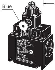
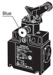
Reset Head (Blue)
The direction of the reset head can be adjusted to any of the four directions.
Built-in Switch
The built-in switch has a direct opening mechanism that forcibly separates the NC contact even when there is contact deposit.
Cover
The cover, with a hinge on its lower part, can be opened by removing the screw of the cover, which ensures ease of maintenance and wiring.
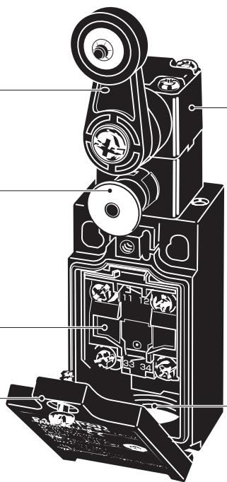
Head
With roller lever models, the direction of the switch head can be adjusted to any of the four directions by loosening the roller lever switch screws at the four corners of the head.
Conduit
A wide variety of conduits is available.
| Size Box | 1-conduit model | 2-conduit mode |
| Pg13.5 | Yes | Yes |
| G1/2 | Yes | Yes |
| 1/2-14NPT | Yes | Yes |
| M20 | Yes | Yes |
| M12 connector | Yes | --- |
Note: M12 connector types are not available for Switches with three contacts.
Contact Form
| Model | Contact | Contact form | Operating pattern | Remarks | ||
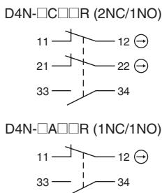
| D4N-□A□R | 1NC/1NO | 11-12 33-34 | 11-12 33-34 | Stroke | ON | Only NC contacts 11-12 have an approved direct opening mechanism. The terminals 11-12 and 33-34 can be used as unlike poles. |
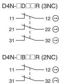
| D4N-□B□R | 2NC | 11-12 31-32 | 11-12 31-32 | Stroke | ON | Only NC contacts 11-12 and 31-32 have an approved direct opening mechanism. The terminals 11-12 and 31-32 can be used as unlike poles. |
| D4N-□C□R | 2NC/1NO | 11-12 21-22 33-34 | 11-12 21-22 33-34 | Stroke | ON | Only NC contacts 11-12 and 21-22 have an approved direct opening mechanism. The terminals 11-12, 21-22, and 33-34 can be used as unlike poles. |
| D4N-□D□R | 3NC | 11-12 21-22 31-32 | 11-12 21-22 31-32 | Stroke | ON | Only NC contacts 11-12, 21-22, and 31-32 have an approved direct opening mechanism. The terminals 11-12, 21-22, and 31-32 can be used as unlike poles. |
Direct Opening Mechanism
1NC/1NO Contact (Slow-action)
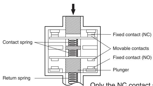
Only the NC contact side has a direct opening mechanism.
When metal deposition occurs, the contacts are separated from each other by the plunger being pushed in.
(Conforms to EN60947-5-1 Direct Opening Operation.)
2NC Contact (Slow-action)
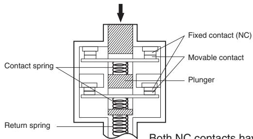
Both NC contacts have a direct opening mechanism.
When metal deposition occurs, the contacts are separated from each other by the plunger being pushed in.
(Conforms to EN60947-5-1 Direct Opening Operation.)
Switches
Note: All units are in millimeters unless otherwise indicated.
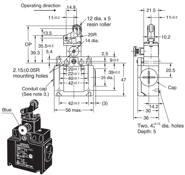
1-conduit Models
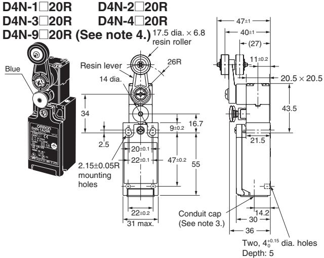
Roller Lever (Resin Lever, Resin Roller)
Adjustable Roller Lever, Form Lock
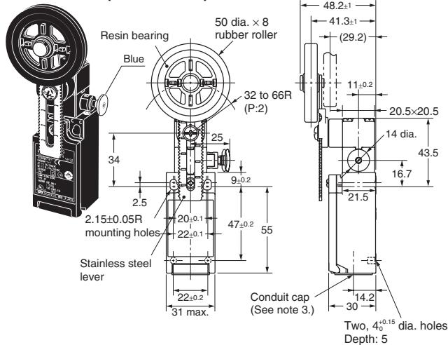
(with Metal Lever, Rubber Roller)
D4N-1□2HR D4N-2□2HR
D4N-3□2HR D4N-4□2HR
D4N-9□2HR (See note 4.)
| Model | D4N-□□20R | D4N-□□2GR (See note 2.) | D4N-□□2HR |
| LF max. | 6.4 N | 5.6 N | 5.4 N |
| LT max. | 55° | 55° | 55° |
| PT 1 (See note 3.) | 18 to 27° | 18 to 27° | 18 to 27° |
| (PT 2) (See note 4.) | (44°) | (44°) | (44°) |
| (TT) (See note 5.) | 80° | 80° | 80° |
| DOF min. (See note 6.) | 20 N | 20 N | 20 N |
| DOT min. (See note 6.) | 50° | 50° | 50° |

Adjustable Roller Lever, Form Lock (with Metal Lever, Resin Roller)
D4N-1□2GR D4N-2□2GR
D4N-3□2GR D4N-4□2GR
D4N-9□2GR (See note 4.)
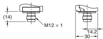
1-conduit M12 Connectors
D4N-9□□□R
Note: 1. Unless otherwise specified, a tolerance of ± 0.4 mm applies to all dimensions.
2. Variation occurs in the simultaneity of contact opening/closing operations of 2NC, 2NC/1NO, and 3NC contacts. Check contact operation.
3. There are a minimum of five turns of the screw thread for a Pg13.5 conduit opening and four turns minimum for a G 1/2 conduit opening.
4. Refer to the following diagram for details on M12 connectors.
Note: 1. Variation occurs in the simultaneity of contact opening/closing operations of 2NC, 2NC/1NO, and 3NC contacts. Check contact operation.
- The operating characteristics of these Switches were measured with the roller lever set at 32mm
- These PT values are possible when the NC contacts are open (OFF).
- These PT values are nominal values possible when the NO contacts are closed (ON). (1NC/1NO models only)
- Nominal value.
- Load and stroke values for the direct opening mechanism. For safe use, always make sure that the minimum values or greater are provided.
1-conduit Models
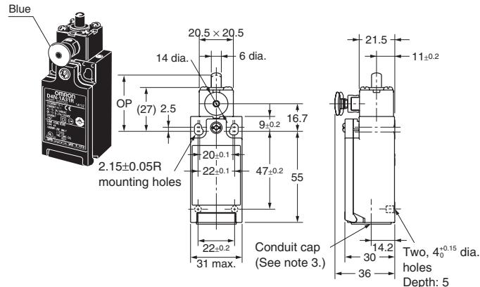
Plunger
D4N-1□31R D4N-2□31R
D4N-3□31R D4N-4□31R
D4N-9□31R (See note 4.)
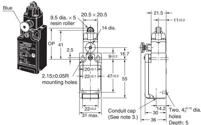
Roller Plunger
D4N-1□32R D4N-2□32R
D4N-3□32R D4N-4□32R
D4N-9□32R (See note 4.)
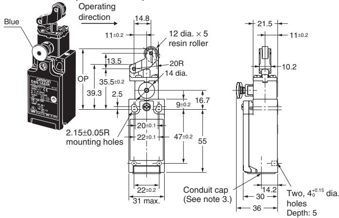
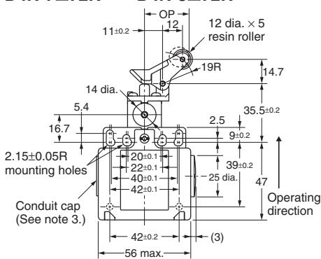
One-way Roller Arm Lever
(Horizontal)
D4N-1□62R D4N-2□62R
D4N-3□62R D4N-4□62R
D4N-9□62R (See note 4.)
One-way Roller Arm Lever
(Vertical)
D4N-1□72B D4N-2□72B
D4N-3□72R D4N-4□72R
D4N-9□7R2 (See note 4.)
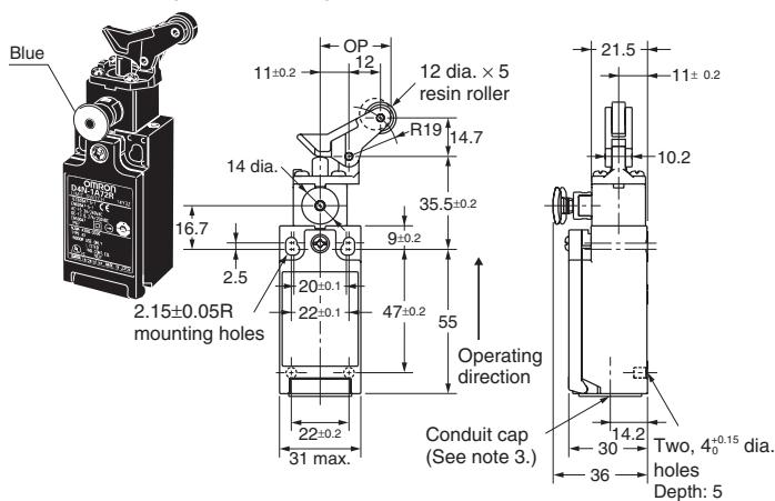
Note: 1. Unless otherwise specified, a tolerance of ± 0.4mm applies to all dimensions.
2. Variation occurs in the simultaneity of contact opening/closing operations of 2NC and 3NC contacts. Check contact operation.
3. There are a minimum of five turns of the screw thread for a Pg13.5 conduit opening and four turns minimum for a G 1/2 conduit opening.
4. Refer to page 273 for details on M12 connectors.
| Model | D4N-□□31R | D4N-□□32R | D4N-□□62R | D4N-□□72R |
| LF max. | 10.8 N | 10.8N | 7.5 N | 7.9 N |
| LT max. | 4.5 mm | 4.5 mm | 7 mm | 7 mm |
| PT 1(See note 2.) | 2 mm | 2 mm | 4 mm | 4 mm |
| (PT 2)(See note 3.) | (2.9 mm) | (2.9 mm) | (5.2 mm) | (4.3 mm) |
| OP | 34 ±0.5 mm | 44.4 ±0.8 mm | 53 ±0.8 mm | 27 ±0.8 mm |
| (TT)(See note 4.) | (6 mm) | (6 mm) | (9 mm) | (9 mm) |
| DOF min.(See note 5.) | 20 N | 20 N | 20 N | 20 N |
| DOT min.(See note 5.) | 3.2 mm | 3.2 mm | 5.8 mm | 4.8 mm |
Note: 1. Variation occurs in the simultaneity of contact opening/closing operations of 2NC, 2NC/1NO, and 3NC contacts. Check contact operation.
2. These PT values are possible when the NC contacts are open (OFF).
3. These PT values are nominal values possible when the NO contacts are closed (ON). (1NC/1NO models only)
4. Nominal value.
5. Load and stroke values for the direct opening mechanism. For safe use, always make sure that the minimum values or greater are provided.
2-conduits Models
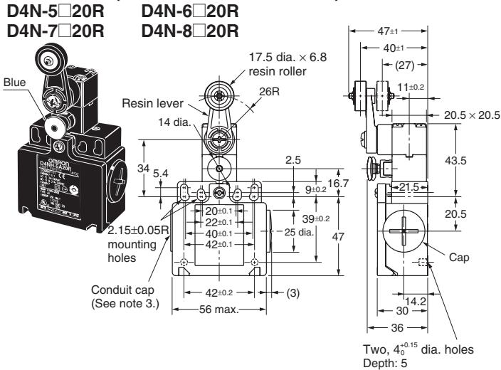
Roller Lever (Resin Lever, Resin Roller)
Adjustable Roller Lever, Form Lock
(with Metal Lever, Resin Roller)
D4N-5□2GR D4N-6□2GR
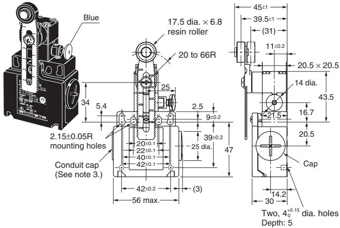
D4N-7□2GR D4N-8□2GR
Adjustable Roller Lever, Form Lock
(with Metal Lever, Rubber Roller)
D4N-5□2HR D4N-6□2HR
D4N-7□2HR D4N-8□2HR
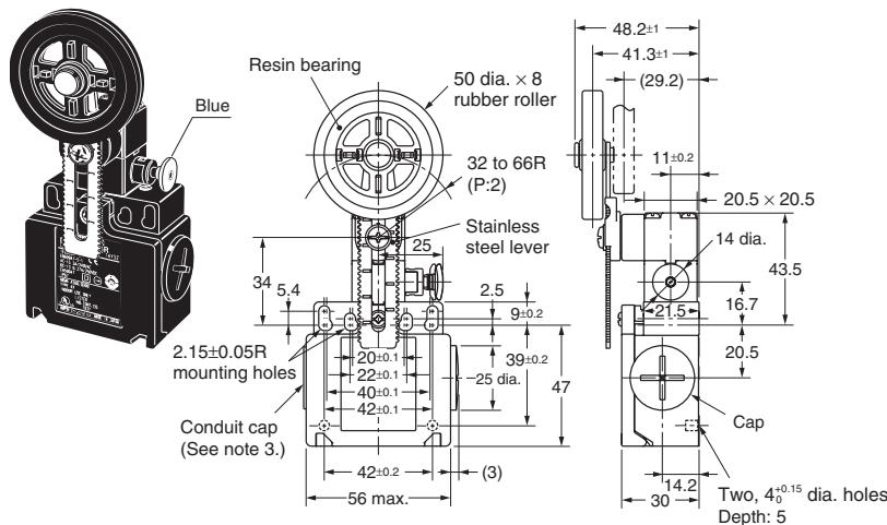
Note: 1. Unless otherwise specified, a tolerance of ± 0.4mm applies to all dimensions.
2. Variation occurs in the simultaneity of contact opening/closing operations of 2NC and 3NC contacts. Check contact operation.
3. There are a minimum of five turns of the screw thread for a Pg13.5 conduit opening and four turns minimum for a G 1/2 conduit opening.
| Model | D4N-□□20R | D4N-□□2GR | D4N-□□2HR |
| LF max. | 6.4 N | 5.6 N | 5.4 N |
| LT max. | 55° | 55° | 55° |
| PT 1 (See note 2.) | 18° to 27° | 18° to 27° | 18° to 27° |
| (PT 2) (See note 3.) | (44°) | (44°) | (44°) |
| (TT) (See note 4.) | 80° | 80° | 80° |
| DOF min. (See note 5.) | 20 N | 20 N | 20 N |
| DOT min. (See note 5.) | 50° | 50° | 50° |
Note: 1. Variation occurs in the simultaneity of contact opening/closing operations of 2NC, 2NC/1NO, and 3NC contacts. Check contact operation.
- These PT values are possible when the NC contacts are open (OFF).
- These PT values are nominal values possible when the NO contacts are closed (ON). (1NC/1NO models only)
- Nominal value.
- Load and stroke values for the direct opening mechanism. For safe use, always make sure that the minimum values or greater are provided.
2-conduits Models
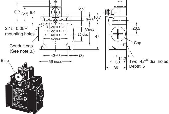
Plunger
D4N-5□31B
D4N-6□31R
DAN-031R DAN 7□31R
D4N-7□3TR
D4N-8□31R
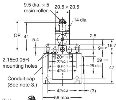
Roller Plunger
D4N-5□32B
D4N-7□32B
D4N-6□32R
D4N-8□32R
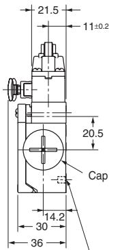
Two, 4_0^+0.15 dia.holes Depth: 5
One-way Roller Arm Lever
(Horizontal)
D4N-5□62R
D4N-7□62R
D4N-6□62R
D4N-8□62R
One-way Roller Arm Lever
(Vertical)
D4N-5□72B
D4N-7□72R
D4N-6□72B
D4N-8□72R
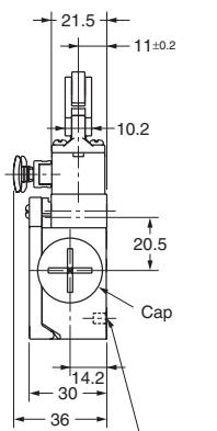
Two, 4_0^+0.15 dia.holes Depth: 5
Note: 1. Unless otherwise specified, a tolerance of ± 0.4mm applies to all dimensions.
2. Variation occurs in the simultaneity of contact opening/closing operations of 2NC and 3NC contacts. Check contact operation.
3. There are a minimum of five turns of the screw thread for a Pg13.5 conduit opening and four turns minimum for a G 1/2 conduit opening.
| Model | D4N-□□31R | D4N-□□32R | D4N-□□62R | D4N-□□72R |
| LF max. | 10.8 N | 10.8N | 7.5 N | 7.9 N |
| LT max. | 4.5 mm | 4.5 mm | 7 mm | 7 mm |
| PT 1 max. (See note 2.) | 2 mm | 2 mm | 4 mm | 4 mm |
| (PT 2) (See note 3.) | (2.9 mm) | (2.9 mm) | (5.2 mm) | (4.3 mm) |
| OP | 34 ±0.5 mm | 44.4 ±0.8 mm | 53 ±0.8 mm | 27 ±0.8 mm |
| (TT) (See note 4.) | (6 mm) | (6 mm) | (9 mm) | (9 mm) |
| DOF min. (See note 5.) | 20 N | 20 N | 20 N | 20 N |
| DOT min. (See note 5.) | 3.2 mm | 3.2 mm | 5.8 mm | 4.8 mm |
Note: 1. Variation occurs in the simultaneity of contact opening/closing operations of 2NC, 2NC/1NO, and 3NC contacts. Check contact operation.
- These PT values are possible when the NC contacts are open (OFF).
- These PT values are nominal values possible when the NO contacts are closed (ON). (1NC/1NO models only)
- Nominal value.
- Load and stroke values for the direct opening mechanism. For safe use, always make sure that the minimum values or greater are provided.
Levers
Refer to the following diagrams for the angles and positions of the dogs.
Roller Lever (D4N-□□20R)

Note: Unless otherwise specified, a tolerance of ± 0.4mm applies to all dimensions.
Safety Precautions
Refer to OMRON SAFETY COMPONENTS SERIES (Y106) for common precautions for Switches and Safety Limit Switches.
CAUTION
Do not use metal connectors or metal conduits with this Switch. Doing so may occasionally result in electric shock.
Precautions for Safe Use
- Do not drop the Switch. Doing so may result in the Switch not performing to its full capacity.
- Do not attempt to disassemble or modify the Switch. Doing so may cause the Switch to malfunction.
- Do not use the Switch where explosive gas, flammable gas, or any other hazardous gas may be present.
- Install the Switch in a location away from close body contact. Not doing so may result in malfunction.
-
Do not use the Switch submerged in oil or water, or in locations continuously subject to splashes of oil or water. Doing so may result in oil or water entering the Switch interior. (The IP67 degree of protection specification for the Switch refers to water penetration while the Switch is submersed in water for a specified period of time.)
-
Protect the head from foreign material. Subjecting the head to foreign material may result in premature wear or damage to the Switch. Although the switch body is protected from penetration by dust or water, the head is not protected from penetration by minute particles or water.
- Turn the power OFF before wiring. Doing so may result in electric shock.
- Install the cover after wiring. Not doing so may result in electric shock.
- Connect a fuse to the Switch in series to protect the Switch from short-circuit damage. Use a fuse with a breaking current 1.5 to 2 times larger than the rated current. To conform to EN ratings, use an IEC60269-compliant 10-A fuse type gl or gG.
- Do not switch circuits for two or more standard loads (250 VAC, 3 A) at the same time. Doing so may adversely affect insulation performance.
- The durability of the Switch is greatly affected by operating conditions. Evaluate the Switch under actual working conditions, before permanent installation and use within a number of switching operations that will not adversely affect the Switch's performance.
-
Be sure to indicate in the machine manufacturer's instruction manual that the user must not attempt to repair or maintain the Switch and must contact the machine manufacturer for any repairs or maintenance.
-
If the Switch is to be used in an emergency stop circuit or in a safety circuit for preventing accidents resulting in injuries or deaths, use a model that has an NC contact equipped with a direct opening mechanism and make sure that the Switch operates in the direct opening mode. Furthermore, secure the Switch with screws or equivalent parts that are tightened in a single direction so that the Switch cannot be easily removed. Then provide a protection cover for the Switch and post a warning label near the Switch.
- Make sure that the actuator is pushed into the lock position. Not doing so may result in the actuator becoming unlocked, causing an accident.
- Always reset the Switch manually. Not doing so may result in damage to the reset function.
- When the Switch locks due to a fault in the system, be sure to reset the Switch manually before resupplying power after confirming the safety of the system.
- Check the Switches before use and inspect regularly, replacing them when necessary. If a Switch is kept pressed for an extended period of time, the components may deteriorate quickly, and the Switch may not release.
- When using the Switch as a safety component, be sure to check the system design for both operational and circuit safety.
Precautions for Correct Use
Environment
- The Switch is intended for indoor use only.
- Do not use the Switch outdoors. Doing so may cause the Switch to malfunction.
- Do not use the Switch where hazardous gases (e.g., H_2S , SO_2 , NH_3 , HNO_3 , Cl_2 ) are present or in locations subject to high temperature and humidity. Doing so may result in damage to the Switch caused by contact failure or corrosion.
-
Do not use the Switch under any of the following conditions.
-
Locations subject to extreme temperature changes.
- Locations where high humidity or condensation may occur.
- Locations subject to excessive vibration.
- Locations where metal dust, processing waste, oil, or chemicals may penetrate through the protective door.
- Locations subject to detergents, thinner, or other solvents.
Mounting Method
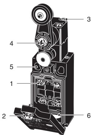
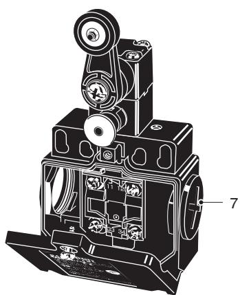
Mounting Screw Tightening Torque
Tighten each of the screws to the specified torque. Loose screws may result in malfunction of the Switch within a short time.
| 1 | Terminal screw | 0.6 to 0.8 N·m |
| 2 | Cover clamping screw | 0.5 to 0.7 N·m |
| 3 | Head clamping screw | 0.5 to 0.6 N·m |
| 4 | Lever clamping screw | 1.6 to 1.8 N·m |
| 5 | Body clamping screw | 0.5 to 0.7 N·m |
| 6 | Conduit mounting connection, M12 adaptor | 1.8 to 2.2 N·m (except 1/2-14NPT) |
| 1.4 to 1.8 N·m (1/2-14NPT) | ||
| 7 | Cap screw | 1.3 to 1.7 N·m |
Switch Mounting
- Mount the Switch using M4 screws and washers and tighten the screws to the specified torque.
- For safety, use screws that cannot be easily removed, or use an equivalent measure to ensure that the Switch is secure.
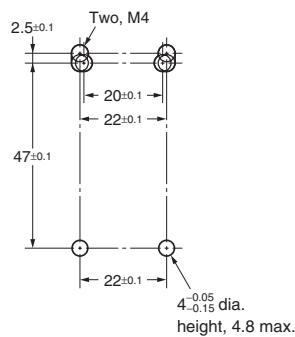
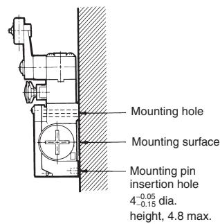
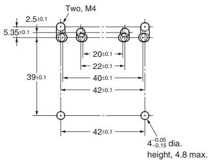
- Secure the Switch with two M4 bolts and washers. Provide studs with a diameter of 4^0.05/_0.15 and a height of 4.8 mm max. at two places, inserting into the holes at the bottom of the Switch as shown below so that the Switch is firmly fixed at four points.
Switch Mounting Holes
One-conduit Type
Two-conduit Type
Changing the Head Direction
By removing the four screws of the head, the mounting direction of the head can be changed. The head can be mounted in four directions. Be sure that no foreign material will enter the head during a change in direction.
Wiring
- When connecting to the terminals via insulating tube and M3.5 crimp terminals, arrange the crimp terminals as shown below so that they do not rise up onto the case or the cover. Applicable lead wire size: AWG20 to AWG18 (0.5 to 0.75 ~mm^2 ). Use lead wires of an appropriate length, as shown below. Not doing so may result in excess length causing the cover to rise and not fit properly.
- Do not push crimp terminals into gaps in the case interior. Doing so may cause damage or deformation of the case.
- Use crimp terminals not more than 0.5mm in thickness. Otherwise, they will interfere with other components inside the case. The crimp terminals shown below are not more than 0.5mm thick.
| Manufacture | Type | Wire size |
| J.S.T. | FV0.5-3.7 (F type) V0.5-3.7 (straight type) | AWG20 (0.5 mm²) |
J.S.T is a Japanese manufacturer.
t: 0.5 mm
dz dia.: 3.7 mm
D dia.: 2.9 mm
B: 6.6 mm
L: 19 mm
F: 7.7 mm
I: 8.0 mm
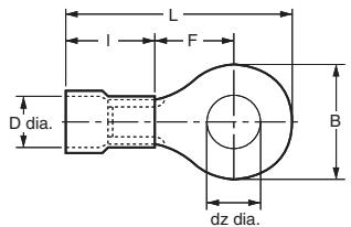
Crimp terminal
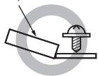
Correct
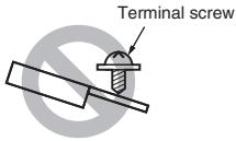
Incorrect
Contact Arrangement
- The following diagrams show the contact arrangements used for screw terminal types and connector types.
Screw Terminal Type
Connector Type
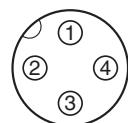
Pin No. (Terminal No.)
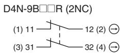
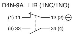
Applicable socket:XS2F (OMRON).
- Refer to the G010 Connector Catalog for details on socket pin numbers and lead wire colors.
Socket Tightening (Connector Type)
- Turn the socket connector screws by hand and tighten until no space remains between the socket and the plug.
- Make sure that the socket connector is tightened securely. Otherwise, the rated degree of protection (IP67) may not be maintained and vibration may loosen the socket connector.
Conduit Opening
- Connect a recommended connector to the opening of the conduit and tighten the connector to the specified torque. The case may be damaged if an excessive tightening torque is applied.
- When using 1/2-14NPT, wind sealing tape around the joint between the connector and conduit opening so that the enclosure will conform to IP67.
-
Use a cable with a suitable diameter for the connector.
-
Attach and tighten a conduit cap to the unused conduit opening when wiring. Tighten the conduit cap to the specified torque. The conduit cap is provided with the Switch (2-conduit types).
Recommended Connectors
Use connectors with screws not exceeding 9mm , otherwise the screws will protrude into the case interior, interfering with other components in the case. The connectors listed in the following table have connectors with thread sections not exceeding 9mm . Use the recommended connectors to ensure conformance to IP67.
| Size | Manufacturer | Model | Applicable cable diameter |
| G1/2 | LAPP | ST-PF1/2 5380-1002 | 6.0 to 12.0 mm |
| Ohm Denki | OA-W1609 | 7.0 to 9.0 mm | |
| OA-W1611 | 9.0 to 11.0 mm | ||
| Pg13.5 | LAPP | S-13.5 5301-5030 | 6.0 to 12.0 mm |
| M20 | LAPP | ST-M20 × 1.5 5311-1020 | 7.0 to 13.0 mm |
| 1/2-14NPT | LAPP | ST-NPT1/2 5301-6030 | 6.0 to 12.0 mm |
| M12 | LAPP | ST-M12 × 1.5 5301-1000 | 3.5 to 7.0 mm |
Use LAPP connectors together with seal packing (JPK-16, GP-13.5, GPM20, or GPM12), and tighten to the specified tightening torque. Seal packing is sold separately.
LAPP is a German manufacturer. Ohm Denki is a Japanese manufacturer.
Before using an M12 type, attaching the provided changing adaptor to the Switch and then connect the recommended connector.
Before using a 2-conduit 1/2-14NPT type, attach the provided changing adaptor to the Switch and then connect the recommended connector.
Storage
Do not store the Switch in locations where hazardous gases (e.g., H_2S , SO_2 , NH_3 , HNO_3 , Cl_2 ) or dust is present, or in locations subject to high temperatures and humidity.
Others
- Do not allow the load current to exceed the rated value.
- Confirm that the seal rubber has no defects before use. If the seal rubber is displaced or raised, or has foreign particles adhered to it, the sealing capability of the seal rubber will be adversely affected.
- Use the correct cover mounting screws only, or the sealing capability of the seal rubber will deteriorate.
- Inspect the Switch regularly.
- With rubber roller lever models, the rubber roller may turn white over time, but this will not affect the quality of operation.
- Use the following recommended countermeasures to prevent telegraphing when using adjustable or long levers.
- Make the rear edge of the dog smooth with an angle of 15^ to 30^ or make it in the shape of a quadratic curve.
- Design the circuit so that no error signal will be generated.
- Use or set a Switch that is operated in one direction only.
Following the release of the D4N-R, production of the D4D-R will be terminated.
Date of Production Termination
Production of the D4D-R Series will be terminated in March 2006.
Product Replacement
1. Dimensions
The D4D-R and D4N-R use the same mounting method, and mounting hole. The multi-contact structure and the extra 4 mm in length, however, are different.
2. Terminal Numbers
For the 2-contact model, the terminals 21, 22, 23, and 24 on the D4D-R are 31, 32, 33, and 34 on the D4N-R.
3. Recommended Terminals
If the recommended terminals are not used, the Switch may not be compatible. Make sure that the Switch is compatible with the terminals.
Comparison of the D4D-R and Substitute Products
| Model | D4N-R |
| Switch color | Very similar |
| Dimensions | Very similar |
| Wiring/connection | Significantly different |
| Mounting method | Completely compatible |
| Ratings/performance | Very similar |
| Operating characteristics | Very similar |
| Operating method | Completely compatible |
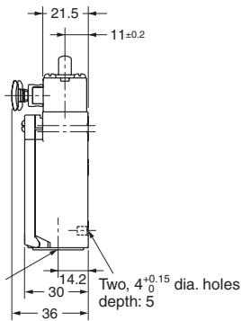
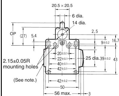
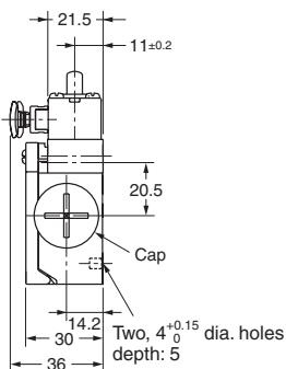
Dimensions (Unit: mm)
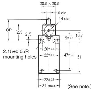
Discontinued Models (1-conduit Plunger-type D4D-R)
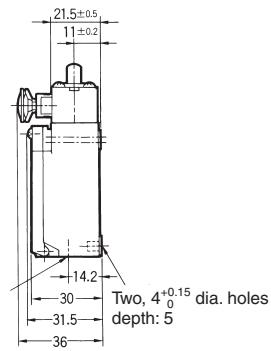
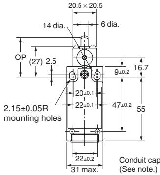
Replacement Products (1-conduit Plunger-type D4N-R)
Discontinued Models (2-conduit Plunger Type D4D-R)
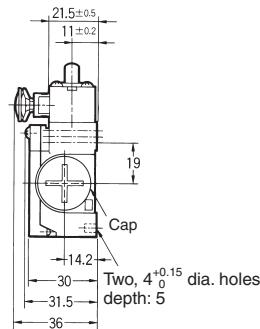
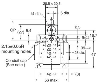
Replacement Products (2-conduit Plunger Type D4N-R)
List of Recommended Substitute Products
: The actuator on the D4D-R is a non-safety type. The D4N-R is recommended for safety applications (form lock type). Be sure to mount it correctly. Using M screws is recommended to comply with European standards. Therefore, the M20 conduit model is recommended for use in new designs.
Safety Limit Switch
| D4D-R product to be discontinued | Recommended substitute product |
| D4D-1520R | D4N-1A20R |
| D4D-2520R | D4N-2A20R |
| D4D-3520R | D4N-3A20R |
| D4D-5520R | D4N-5A20R |
| D4D-6520R | D4N-6A20R |
| D4D-1531R | D4N-1A31R |
| D4D-2531R | D4N-2A31R |
| D4D-3531R | D4N-3A31R |
| D4D-5531R | D4N-5A31R |
| D4D-6531R | D4N-6A31R |
| D4D-1532R | D4N-1A32R |
| D4D-2532R | D4N-2A32R |
| D4D-3532R | D4N-3A32R |
| D4D-5532R | D4N-5A32R |
| D4D-6532R | D4N-6A32R |
| D4D-1562R | D4N-1A62R |
| D4D-2562R | D4N-2A62R |
| D4D-3562R | D4N-3A62R |
| D4D-5562R | D4N-5A62R |
| D4D-6562R | D4N-6A62R |
| D4D-1572R | D4N-1A72R |
| D4D-2572R | D4N-2A72R |
| D4D-3572R | D4N-3A72R |
| D4D-5572R | D4N-5A72R |
| D4D-6572R | D4N-6A72R |
| D4D-152HR | D4N-1A2HR |
| D4D-252HR | D4N-2A2HR |
| D4D-352HR | D4N-3A2HR |
| D4D-1521R | D4N-1A2GR |
| D4D-2521R | D4N-2A2GR |
| D4D-3521R | D4N-3A2GR |
| D4D-5521R | D4N-5A2GR |
| D4D-6521R | D4N-6A2GR |
| D4D-1527R | D4N-1A2HR |
| D4D-2527R | D4N-2A2HR |
| D4D-3527R | D4N-3A2HR |
| D4D-5527R | D4N-5A2HR |
| D4D-6527R | D4N-6A2HR |
| D4D-R product to be discontinued | Recommended substitute product |
| D4D-1A20R | D4N-1B20R |
| D4D-2A20R | D4N-2B20R |
| D4D-3A20R | D4N-3B20R |
| D4D-5A20R | D4N-5B20R |
| D4D-6A20R | D4N-6B20R |
| D4D-1A31R | D4N-1B31R |
| D4D-2A31R | D4N-2B31R |
| D4D-3A31R | D4N-3B31R |
| D4D-5A31R | D4N-5B31R |
| D4D-6A31R | D4N-6B31R |
| D4D-1A32R | D4N-1B32R |
| D4D-2A32R | D4N-2B32R |
| D4D-3A32R | D4N-3B32R |
| D4D-5A32R | D4N-5B32R |
| D4D-6A32R | D4N-6B32R |
| D4D-1A62R | D4N-1B62R |
| D4D-2A62R | D4N-2B62R |
| D4D-3A62R | D4N-3B62R |
| D4D-5A62R | D4N-5B62R |
| D4D-6A62R | D4N-6B62R |
| D4D-1A72R | D4N-1B72R |
| D4D-2A72R | D4N-2B72R |
| D4D-3A72R | D4N-3B72R |
| D4D-5A72R | D4N-5B72R |
| D4D-6A72R | D4N-6B72R |
| D4D-1A2HR | D4N-1B2HR |
| D4D-2A2HR | D4N-2B2HR |
| D4D-3A2HR | D4N-3B2HR |
| D4D-1A21R | D4N-1B2GR |
| D4D-2A21R | D4N-2B2GR |
| D4D-3A21R | D4N-3B2GR |
| D4D-5A21R | D4N-5B2GR |
| D4D-6A21R | D4N-6B2GR |
| D4D-1A27R | D4N-1B2HR |
| D4D-2A27R | D4N-2B2HR |
| D4D-3A27R | D4N-3B2HR |
| D4D-5A27R | D4N-5B2HR |
| D4D-6A27R | D4N-6B2HR |
Warranty and Application Considerations
| Read and Understand this Catalog |
| Please read and understand this catalog before purchasing the products. Please consult your OMRON representative if you have any questions or comments. |
Warranty and Limitations of Liability
WARRANTY
OMRON's exclusive warranty is that the products are free from defects in materials and workmanship for a period of one year (or other period if specified) from date of sale by OMRON.
OMRON MAKES NO WARRANTY OR REPRESENTATION, EXPRESS OR IMPLIED, REGARDING NON-INFRINGEMENT, MERCHANTABILITY, OR FITNESS FOR PARTICULAR PURPOSE OF THE PRODUCTS. ANY BUYER OR USER ACKNOWLEDGES THAT THE BUYER OR USER ALONE HAS DETERMINED THAT THE PRODUCTS WILL SUITABLY MEET THE REQUIREMENTS OF THEIR INTENDED USE. OMRON DISCLAIMS ALL OTHER WARRANTYES, EXPRESS OR IMPLIED.
LIMITATIONS OF LIABILITY
OMRON SHALL NOT BE RESPONSIBLE FOR SPECIAL, INDIRECT, OR CONSEQUENTIAL DAMAGES, LOSS OF PROFITS, OR COMMERCIAL LOSS IN ANY WAY CONNECTED WITH THE PRODUCTS, WHETHER SUCH CLAIM IS BASED ON CONTRACT, WARRANTY, NEGLIGENCE, OR STRICT LIABILITY.
In no event shall the responsibility of OMRON for any act exceed the individual price of the product on which liability is asserted. IN NO EVENT SHALL OMRON BE RESPONSIBLE FOR WARRANTY, REPAIR, OR OTHER CLAIMS REGARDING THE PRODUCTS UNLESS OMRON'S ANALYSIS CONFIRMS THAT THE PRODUCTS WERE PROPERLY HANDLED, STORED, INSTALLED, AND MAINTAINED AND NOT SUBJECT TO CONTAMINATION, ABUSE, MISUSE, OR INAPPROPRIATE MODIFICATION OR REPAIR.
Application Considerations
SUITABILITY FOR USE
OMRON shall not be responsible for conformity with any standards, codes, or regulations that apply to the combination of products in the customer's application or use of the products.
Take all necessary steps to determine the suitability of the product for the systems, machines, and equipment with which it will be used.
Know and observe all prohibitions of use applicable to this product.
NEVER USE THE PRODUCTS FOR AN APPLICATION INVOLVING SERIOUS RISK TO LIFE OR PROPERTY WITHOUT ENSURING THAT THE SYSTEM AS A WHOLE HAS BEEN DESIGNED TO ADDRESS THE RISKS, AND THAT THE OMRON PRODUCTS ARE PROPERLY RATED AND INSTALLED FOR THE INTENDED USE WITHIN THE OVERALL EQUIPMENT OR SYSTEM.
Disclaimers
PERFORMANCE DATA
Performance data given in this catalog is provided as a guide for the user in determining suitability and does not constitute a warranty. It may represent the result of OMRON's test conditions, and the users must correlate it to actual application requirements. Actual performance is subject to the OMRON Warranty and Limitations of Liability.
CHANGE IN SPECIFICATIONS
Product specifications and accessories may be changed at any time based on improvements and other reasons. Consult with your OMRON representative at any time to confirm actual specifications of purchased product.
DIMENSIONS AND WEIGHTS
Dimensions and weights are nominal and are not to be used for manufacturing purposes, even when tolerances are shown.
ALL DIMENSIONS SHOWN ARE IN MILLIMETERS.
To convert millimeters into inches, multiply by 0.03937. To convert grams into ounces, multiply by 0.03527.
- New Series of manual-reset Limit Switch
- Model Number Structure
- D4N-□□□R
- 123
- Conduit/Connector size
- Built-in Switch
- Head and Actuator
- Specifications
- Standards and EC Directives
- Approved Standard Ratings
- Structure
- Safety-oriented Lever Setting
- Reset Head (Blue)
- Built-in Switch
- Cover
- Head
- Conduit
- Contact Form
- Direct Opening Mechanism
- Switches
- 1-conduit Models
- 2-conduits Models
- Levers
- Safety Precautions
- CAUTION
- Precautions for Safe Use
- Precautions for Correct Use
- Environment
- Mounting Method
- Mounting Screw Tightening Torque
- Switch Mounting
- Switch Mounting Holes
- One-conduit Type
- Two-conduit Type
- Changing the Head Direction
- Wiring
- Contact Arrangement
- Screw Terminal Type
- Connector Type
- Socket Tightening (Connector Type)
- Conduit Opening
- Recommended Connectors
- Storage
- Others
- Product Replacement
- Dimensions
- Terminal Numbers
- Recommended Terminals
- Dimensions (Unit: mm)
- List of Recommended Substitute Products
- Safety Limit Switch
- Warranty and Application Considerations
- Warranty and Limitations of Liability
- WARRANTY
- LIMITATIONS OF LIABILITY
- Application Considerations
- SUITABILITY FOR USE
- Disclaimers
- PERFORMANCE DATA
- CHANGE IN SPECIFICATIONS
- DIMENSIONS AND WEIGHTS
Brand : OMRON
Model : D4N-R
Category : Limit switches