
CJ1W-MCH71 - Motion Controller OMRON - Free user manual and instructions
Find the device manual for free CJ1W-MCH71 OMRON in PDF.


User questions about CJ1W-MCH71 OMRON
0 question about this device. Answer the ones you know or ask your own.
Ask a new question about this device
Download the instructions for your Motion Controller in PDF format for free! Find your manual CJ1W-MCH71 - OMRON and take your electronic device back in hand. On this page are published all the documents necessary for the use of your device. CJ1W-MCH71 by OMRON.
USER MANUAL CJ1W-MCH71 OMRON
OMRON products are manufactured for use according to proper procedures by a qualified operator and only for the purposes described in this manual.
The following conventions are used to indicate and classify precautions in this manual. Always heed the information provided with them. Failure to heed precautions can result in injury to people or damage to property.
DANGER
Indicates an imminently hazardous situation which, if not avoided, will result in death or serious injury. Additionally, there may be severe property damage.
WARNING
Indicates a potentially hazardous situation which, if not avoided, could result in death or serious injury. Additionally, there may be severe property damage.
Caution
Indicates a potentially hazardous situation which, if not avoided, may result in minor or moderate injury, or property damage.
OMRON Product References
All OMRON products are capitalized in this manual. The word "Unit" is also capitalized when it refers to an OMRON product, regardless of whether or not it appears in the proper name of the product.
The abbreviation "Ch," which appears in some displays and on some OMRON products, often means "word" and is abbreviated "Wd" in documentation in this sense.
The abbreviation "PLC" means Programmable Controller. "PC" is used, however, in some Programming Device displays to mean Programmable Controller.
Visual Aids
The following headings appear in the left column of the manual to help you locate different types of information.
Note Indicates information of particular interest for efficient and convenient operation of the product.
1,2,3... 1. Indicates lists of one sort or another, such as procedures, checklists, etc.
OMRON, 2004
All rights reserved. No part of this publication may be reproduced, stored in a retrieval system, or transmitted, in any form, or by any means, mechanical, electronic, photocopying, recording, or otherwise, without the prior written permission of OMRON.
No patent liability is assumed with respect to the use of the information contained herein. Moreover, because OMRON is constantly striving to improve its high-quality products, the information contained in this manual is subject to change without notice. Every precaution has been taken in the preparation of this manual. Nevertheless, OMRON assumes no responsibility for errors or omissions. Neither is any liability assumed for damages resulting from the use of the information contained in this publication.
Introduction
We are flattered that you have purchased OMRON SYSMAC CS/CJ-series advanced Motion Control Unit.
Motion control Unit CS1W-MCH71/CJ1W-MCH71 (the abbreviation "MC Unit" is in this mean) is a high performance CPU unit of the programmable controller SYSMAC CS/CJ-series that has been produced by OMRON's advanced technology for control and abundant experience.
This instruction manual describes MC Unit's specifications and procedures for operation.
Please read each section in its entirety and be sure you understand the information provided in the section and relate sections before attempting any of the procedures or operation given.
MC Units
Unit Versions
Notation of Unit Versions on Products
A "unit version" has been introduced to manage MC Units according to differences in functionality accompanying Unit upgrades.
The unit version is given to the right of the lot number on the nameplate of the applicable MC Units, as shown below.
MC Unit
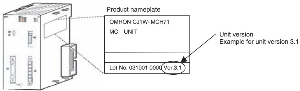
Identifying Unit Versions
The unit version of the MC Units begins at version 2.0.
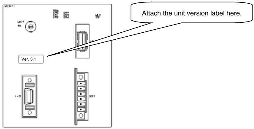
A unit version label is provided with the Advanced Motion Control Unit. This label can be attached to the front of the Motion Control Unit to differentiate between Motion Control Units of different Unit versions.
Confirming Unit Versions with Support Software
The unit version 2.1 or later can be confirmed in Unit Manufacturing Information of CX-Programmer version 4.0 or higher. Unit version 2.0 cannot be confirmed in Unit Manufacturing Information. Use the CX-Motion-MCH Support Tool for Motion Control Units to confirm the unit version.
Example: Confirming Unit Version 2.1 or Later Using CX-Programmer Version 4.0 or Higher
- In the I/O Table Window, right-click the Motion Control Unit and select Unit Manufacturing Information.
- The following Unit Manufacturing Information Dialog Box will be displayed.
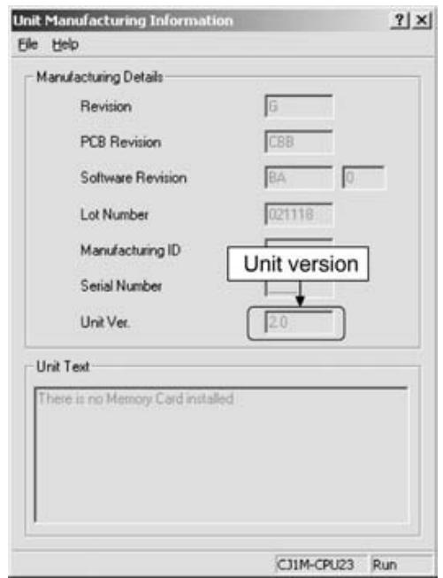
- Unit version 3.1 will be displayed in the Unit Manufacturing Information Dialog Box.
Example: Confirming Unit Version 3.0 Using CX-Motion-MCH Support Tool
Use the CX-Motion-MCH Support Tool for Motion Control Units to confirm the unit version, as shown in the following table.
| Method for confirming the internal system software version | The system software version in the Motion Control Unit can be checked in the Unit information from the online menus. | ||
| Corresponds to the unit version | Internal system software version | ||
| CJ1W-MCH71 | CS1W-MCH71 | ||
| Unit Ver. 2.0: | 1.05xxxx | 1.05xxxx | |
| Unit Ver. 2.1: | 1.06xxxx | --- | |
| Unit Ver. 3.0: | 1.07xxxx | 1.08xxxx | |
| Unit Ver. 3.1 | 1.09xxxx | 1.09xxxx | |
Functions Supported by CJ1W-MCH71 Units Version 2.1 or Later
| Unit version | Unit Ver. 2.0 | Unit Ver. 2.1 | Unit Ver. 3.0 | Unit Ver. 3.1 | |
| Internal system software version | 1.05 | 1.06 | 1.07 | 1.09 | |
| MC Unit model | CJ1W-MCH71 | ||||
| Functions | Reading unit version function | Not supported | Supported | Supported | Supported |
| Expanded allocations in Custom I/O Area | Not supported | Supported | Supported | Supported | |
| Data tracing | Not supported | Not supported | \( Supported^{*1} \) | \( Supported^{*1} \) | |
| Debugging | Not supported | Not supported | \( Supported^{*1} \) | \( Supported^{*1} \) | |
| Zones | Not supported | Not supported | \( Supported^{*1} \) | \( Supported^{*1} \) | |
| Signed master axis MOVELINK com- mand | Not supported | Not supported | Supported | Supported | |
| Indirect writing of position data | Not supported | Not supported | Supported | Supported | |
| Setting the number of parallel branches for each task | Not supported | Not supported | \( Supported^{*1} \) | \( Supported^{*1} \) | |
| Present position preset to establish origin | Not supported | Not supported | \( Supported^{*1} \) | \( Supported^{*1} \) | |
| Status of program start bit | Not supported | Not supported | Supported | Supported | |
| Servo OFF for deceleration stop signal | Not supported | Not supported | \( Supported^{*1} \) | \( Supported^{*1} \) | |
| Re-execution of WAIT command | Not supported | Not supported | Supported | Supported | |
| Main power status | Not supported | Not supported | Supported | Supported | |
| Servo Driver status | Not supported | Not supported | Supported | Supported | |
| Increased precision of CAMBOX com- mand | Not supported | Not supported | Supported | Supported | |
| Improved restarting after restoration | --- | --- | --- | Supported | |
| Expanded bank switching for interpo- lation acceleration/deceleration times | --- | --- | --- | Supported | |
| Internal overrides | --- | --- | --- | Supported | |
| Connecting to SMARTSTEP Junior Servo Drivers | --- | --- | --- | \( Supported^{*2} \) | |
| Improved backup and restore func- tions | --- | --- | --- | \( Supported^{*2} \) | |
| Program and CAM data read protec- tion | --- | --- | --- | \( Supported^{*2} \) | |
| Applicable Support Tool | CX-Motion-MCH· Functions for unit version 3.0 indicated by “*1” can be used with CX- Motion-MCH version 2.0 or higher.· Functions for unit version 3.1 indicated by “*2” can be used with CX- Motion-MCH version 2.1 or higher. | ||||
CJ1W-MCH71 Unit Versions and Manufacturing Dates/Lot Numbers
| Classification | Type | Model | Manufacturing dates | |||
| Up to early November 2004 | From middle of November 2004 | From early June 2005 | From early July 2007 | |||
| CPU Bus Unit | MC Unit | CJ1W-MCH71 | Unit version 2.0 | Unit version 2.1 (Lot No.: 041117 and later) | Unit version 3.0 (Lot No.: 050615 and later) | Unit version 3.1 (Lot No.: 070615 and later) |
Functions Supported by CS1W-MCH71 Units Version 2.0 or Later
| Unit version | Pre-Ver. 2.0 | Unit Ver. 2.0 | Unit Ver. 3.0 | Unit Ver. 3.1 | |
| Internal system software version | 1.00 to 1.04 | 1.05 | 1.08 | 1.09 | |
| MC Unit model | CS1W-MCH71 | ||||
| Functions | Jogging | --- | Supported | Supported | Supported |
| Communications levels | --- | Supported | Supported | Supported | |
| Communications cycle and unit cycle | --- | Supported | Supported | Supported | |
| LATCH command processing time | --- | Supported | Supported | Supported | |
| Latch status refresh time | --- | Supported | Supported | Supported | |
| Using interpolation commands during pass operation | --- | Supported | Supported | Supported | |
| Acceleration/deceleration time during pass operation | --- | Supported | Supported | Supported | |
| Deceleration time during pass operation | --- | Supported | Supported | Supported | |
| Torque to position control switching | --- | Supported | Supported | Supported | |
| Expanded allocations in Custom I/O Area | --- | --- | Supported*1 | Supported*1 | |
| Digital input values changed to improve noise immunity | --- | --- | Supported | Supported | |
| Faster unit cycle and communications cycle times | --- | --- | Supported | Supported | |
| Signed master axis MOVELINK command | --- | --- | Supported | Supported | |
| Indirect writing of position data | --- | --- | Supported | Supported | |
| Status of program start bit | --- | --- | Supported | Supported | |
| Re-execution of WAIT command | --- | --- | Supported | Supported | |
| Main power status | --- | --- | Supported | Supported | |
| Servo Driver status | --- | --- | Supported | Supported | |
| Increased precision of CAMBOX command | --- | --- | Supported | Supported | |
| Data tracing | --- | --- | Supported*1 | Supported*1 | |
| Debugging | --- | --- | Supported*1 | Supported*1 | |
| Zones | --- | --- | Supported*1 | Supported*1 | |
| Setting the number of parallel branches for each task | --- | --- | Supported*1 | Supported*1 | |
| Present position preset to establish origin | --- | --- | Supported*1 | Supported*1 | |
| Servo OFF for deceleration stop signal | --- | --- | Supported*1 | Supported*1 | |
| Improved restarting after restoration | --- | --- | --- | Supported | |
| Expanded bank switching for interpolation acceleration/deceleration times | --- | --- | --- | Supported | |
| Internal overrides | --- | --- | --- | Supported | |
| Connecting to SMARTSTEP Junior Servo Drivers | --- | --- | --- | Supported*2 | |
| Improved backup and restore functions | --- | --- | --- | Supported*2 | |
| Program and CAM data read protection | --- | --- | --- | Supported*2 | |
| Applicable Support Tool | CX-Motion-MCH • Functions for unit version 3.0 indicated by “**1” can be used with CX-Motion-MCH version 2.0 or higher. • Functions for unit version 3.1 indicated by “**2” can be used with CX-Motion-MCH version 2.1 or higher. | ||||
CS1W-MCH71 Unit Versions and Manufacturing Dates/Lot Numbers
| Classification | Type | Model | Manufacturing dates | |||
| From early June 2004 | From July 2004 | From March 2007 | From early July 2007 | |||
| CPU Bus Unit | MC Unit | CS1W-MCH71 | Pre-Ver. 2.0 | Unit version 2.0 (Lot No.: 040715 and later) | Unit version 3.0 (Lot No.: 070313 and later) | Unit version 3.1 (Lot No.: 070615 and later) |
Guide to Version Upgrades
Guide to CJ1W-MCH71 Version Upgrade
Function Upgrades from Unit Version 3.0 to 3.1
Restarting after Restoration
| Previous versions (Unit Ver. 3.0 and earlier) | Current version (Unit Ver. 3.1) |
| After data has been restored from the CPU Unit's flash memory, the Unit must be restarted by cycling the CPU Unit's power supply. | After data has been restored from the CPU Unit's flash memory, the Unit is restarted using a bit between A50100 and A50115 in the Auxiliary Area of the CPU Unit. For details, refer to 7-1 Overview. |
Expanded Bank Switching for Interpolation Acceleration/Deceleration Times
| Previous versions (Unit Ver. 3.0 and earlier) | Current version (Unit Ver. 3.1) |
| The acceleration time and deceleration time used for interpolation operations cannot be set separately. | The acceleration time and deceleration time used for interpolation operations can be set separately. P00004, bit 13: Bank switching method selection 0: Select the same bank for acceleration and deceleration (same as for version 3.0). 1: Select different banks for the acceleration time and deceleration time. Parameters P00M11 to P00M15 are used to set acceleration times, and P00M16 to P00M20 are used to set deceleration times. For details, refer to 6-1 Basic Information. |
Internal Overrides
| Previous versions (Unit Ver. 3.0 and earlier) | Current version (Unit Ver. 3.1) |
| There is a function for changing the axis feed rate from a ladder program, but not from a motion program. | The feed rate when the following commands are executed can be changed from a motion program. Commands for which an override can be speci-fied from the motion program: MOVE Rapid feed rate DATUM Origin return feed rate MOVEI Rapid feed rate, external position-ing rate MOVET Rapid feed rate The actual speed is as follows: Actual speed = Axis feed rate x (Axis override + Internal override) For details, refer to 6-1 Basic Information. |
Connecting to SMART STEP Junior Servo Drivers
| Previous versions (Unit Ver. 3.0 and earlier) | Current version (Unit Ver. 3.1) |
| Cannot be connected. | Can be connected. |
Backup and Restore Functions
| Previous versions (Unit Ver. 3.0 and earlier) | Current version (Unit Ver. 3.1) |
| The origin compensation value when an absolute encoder is used is backed up using the CPU Unit's easy backup function. | Origin compensation values can be backed up even with CX-Motion-MCH version 2.1. For details, refer to Section 11 Backup and Restore in the CX-Motion-MCH Operation Manual (Cat. No. W448). |
Program and CAM Data Read Protection
| Previous versions (Unit Ver. 3.0 and earlier) | Current version (Unit Ver. 3.1) |
| There is no program and CAM data read protection. | The CX-Motion-MCH version 2.1 read protection function (password setting), can be used to prevent third-parties from reading program and CAM data. For details, refer to Section 12 Read Protection in the CX-Motion-MCH Operation Manual (Cat. No. W448). |
Improved Functions from Unit Ver. 2.1 Compared to Unit Ver. 3.0
Data Tracing
| Previous versions (Unit Ver. 2.1 and earlier) | Current version (Unit Ver. 3.0) |
| Data tracing is not supported. | A data tracing function is provided that can simultaneously collect a maximum of 32 data items. This function does not affect previous functionality. Previously reserved parameters and variables are used to set and reference data trace conditions and status. For details, refer to 9-6 Data Tracing. |
Debugging
| Previous versions (Unit Ver. 2.1 and earlier) | Current version (Unit Ver. 3.0) |
| Breakpoints cannot be set. | Debugging is supported using breakpoints that are set using the Support Tool, and debugging is supported for direct operation. These functions do not affect previous functionality, but the following bit has been added to the Unit status to indicate that debugging is being executed from the Support Tool. • CIO n+15, bit 09: Operating mode (Reserved in previous unit versions.) 0: Normal mode 1: Support Tool mode (debugging) |
Zones
| Previous versions (Unit Ver. 2.1 and earlier) | Current version (Unit Ver. 3.0) |
| Zones are not supported. | A maximum of 32 zone bits are available. Zone bit: A bit that turns ON when any variable is within the set range, and turns OFF when the variable is outside of the range. The previous function and the new function can be switched using the following parameter. • Parameter number: P00011 (Reserved in previous unit versions.) • Setting: 0 to 32 0: Default. Same as previous function. 1 to 32: Use zone bits 1 to 32. Parameters and variables that were previously reserved are used to set zone upper and lower limits. For details, refer to 9-7 Zones. |
Signed Master Axis MOVELINK Command
| Previous versions (Unit Ver. 2.1 and earlier) | Current version (Unit Ver. 3.0) |
| The main axis input sign is ignored and data is read as an absolute travel distance. | The main axis input sign is evaluated and the data is read as a signed travel distance. This function enables the main axis to use the feedback speed of an axis traveling at low speed. |
Indirect Writing of Position Data
| Previous versions (Unit Ver. 2.1 and earlier) | Current version (Unit Ver. 3.0) |
| Position data can be indirectly read but cannot be indirectly written. | Position data can be both read and written indirectly. Example: Indirect Writing @ PL0000 = 1234; “1234” will be assigned as the contents of the address set in PL0000. This function does not affect previous functionality. |
Setting the Number of Parallel Branches for Each Task
| Previous versions (Unit Ver. 2.1 and earlier) | Current version (Unit Ver. 3.0) |
| The number of branches and the number of commands that can be executed are the same for each task. | The number of branches and the number of instructions that can be executed can be set individually for each task, enabling fine adjustment of the Unit cycle. The previous function and the new function can be switched using the following parameter. • Parameter number: P00004 • Bit 11 (Reserved in previous unit versions.) 0: Default. Same as previous function. 1: Individually set the number of branches and the number of commands that can be executed in each task. Previously reserved parameters are used to set the number of parallel branches individually for each task. |
Present Position Preset to Establish Origin
| Previous versions (Unit Ver. 2.1 and earlier) | Current (Unit Ver. 3.0) |
| The origin is not established when the present position is set to the preset value. | The origin is established when the present position is set to the preset value. The previous function and the new function can be switched using the following parameter. • Parameter number: P00004 • Bit 12 (Reserved in previous unit versions.) 0: Default. Same as previous function. 1: Origin established for preset. |
Program Start Bit Status
| Previous versions (Unit Ver. 2.1 and earlier) | Current (Unit Ver. 3.0) |
| An operation completed bit alone cannot be used to detect the end of programs with processing times that are shorter than the Unit cycle time. | The start bit ON/OFF status in the CPU Unit is output to the task status bit. Example for Axis 1: • n+17 bit 06: start bit (Reserved in previous unit versions.) 0: Start bit from CPU Unit OFF 1: Start bit from CPU Unit ON The end of the relevant program can be detected if this bit is ON and the operation completed bit is ON. |
Servo OFF for Deceleration Stop Signal
| Previous versions (Unit Ver. 2.1 and earlier) | Current (Unit Ver. 3.0) |
| When the deceleration stop signal for the Unit turns ON, all axes are decelerated to a stop. | When the deceleration stop signal for the Unit turns ON, the servo can be turned OFF for all axes. The operation for servo OFF is set in the Servo Driver parameters. The previous function and the new function can be switched using the following parameter. • Parameter number: P00004 • Bit 10 (Reserved in previous unit versions.) 0: Default. Same as previous function. 1: Servo OFF |
Re-execution of WAIT Command
| Previous versions (Unit Ver. 2.1 and earlier) | Current (Unit Ver. 3.0) |
| If the program is stopped while WAIT command execution is in effect (i.e., when the deceleration stop bit is ON) and then re-started by setting the Start Mode to 1, the program is started from the next block after the WAIT command. | If the program is stopped while WAIT command execution is in effect (i.e., when the deceleration stop bit is ON) and then re-started by setting the Start Mode to 1, the WAIT command is re-executed. |
Main Power Status
| Previous versions (Unit Ver. 2.1 and earlier) | Current (Unit Ver. 3.0) |
| The main power status (ON/OFF) is written to a system variable. | The main power status (ON/OFF) is written to both a system variable and a status bit for each axis. Example for Axis 1: • x+32 bit 12: Main power ON bit (reserved in previous unit versions) 0: Main power OFF 1: Main power ON The servo can be effectively locked from the CPU Unit after confirming that this bit is ON. |
Servo Driver Status
| Previous versions (Unit Ver. 2.1 and earlier) | Current (Unit Ver. 3.0) |
| The Servo Driver warning and alarm codes are stored in the error log. The Servo status (torque limit, limit inputs, etc.) is output to system variables (SW021C and SW021D for axis 1.) | In addition to the functionality supported in previous unit versions, Servo Driver warning codes, alarm codes, and status (torque limit, limit inputs, etc.) are also output to the following output variables that were reserved in previous unit versions. OW0210: Axis 1 Warning code/alarm code OW0211: Axis 1 Status (same as SW021C) OW0212: Axis 1 Status (same as SW021D) to OW026D: Axis 32 Warning code/alarm code OW026E: Axis 32 Status (Same as SW07EC) OW026F: Axis 32 Status (Same as SW07ED) |
Compliance with RoHS Directive
| Previous versions (Unit Ver. 2.1 and earlier) | Current version (Unit Ver. 3.0) | ||
| Lead was included in the cream solder used to mount chip components, in the flow solder used in assembly, and in thread solder. | As shown below, lead is not used. There is no change in specifications (including outer appearance) resulting from this change. | ||
| Solder type | Main components | Solder type | Main components |
| Cream solder | Tin and lead | Cream solder | (1) Tin, silver, indium, and bismuth (2) Tin, silver, and copper |
| Flow solder | Tin and lead | ||
| Thread solder | Tin and lead | Flow solder | (1) Tin and copper (2) Tin, silver, and copper |
| Thread solder | Tin, silver, and copper | ||
| Note: Either 1 or 2 shown above is used. | |||
| There is no mark indicating compliance with the RoHS Directive. | The RoHS compliance mark is displayed. | ||
Increased Precision of CAMBOX Command
| Previous versions (Unit Ver. 2.1 and earlier) | Current (Unit Ver. 3.0) |
| If the slave axis CAM table is switched during continuous master axis travel, part of the slave axis travel is eliminated when the CAM table is switched. Example: CAMBOX [J01]1 [J02]10000 K10000 Q8 B0;Cam 1 CAMBOX [J01]2 [J02]10000 K10000 Q8 B0;Cam 2 CAMBOX [J01]3 [J02]10000 K10000 Q8 B0;Cam 3 Slave axis displacement 0 Slave axis speed 0 This amount of travel is eliminated. | The slave axis will travel the set amount, even if the slave axis CAM table is switched during continuous master axis travel. Example: CAMBOX [J01]1 [J02]10000 K10000 Q8 B0;Cam 1 CAMBOX [J01]2 [J02]10000 K10000 Q8 B0;Cam 2 CAMBOX [J01]3 [J02]10000 K10000 Q8 B0;Cam3 Slave axis displacement 0 Slave axis speed 0 This amount of travel is eliminated. |
Functions Added in Version Upgrade
The following table provides a comparison between the functions provided in the upgrade to unit version 2.1 or later of CJ1W-MCH71 SYSMAC CJ-series Motion Control Units from the previous unit version 2.0.
Reading Unit Versions
| Previous version (Unit Ver. 2.0) | Present version (Unit Ver. 2.1) |
| The MC Unit's unit version code could not be read by accessing the Unit Manufacturing Information in CX-Programmer Ver.4.0. | The MC Unit's unit version code can be read by accessing the Unit Manufacturing Information in CX-Programmer Ver.4.0. |
Expanded Allocations in Custom I/O Area
| Previous version (Unit Ver. 2.0) | Present version (Unit Ver. 2.1) |
| Only the I/O variable area determined in advance could be allocated to the Cus-tom I/O Area. | In addition to the I/O variable area, sys-tem variables, global general variables, position data, and task variables for user-specified addresses can be allocated in the Custom I/O Area. |
Expanded Custom I/O Area Allocations
Overview
The CPU Unit can control MC Units with the following three different methods of data I/O.
- Data exchange with allocated bit area words.
- Data exchange with allocated DM Area words.
- Data exchange with allocated Custom Area words.
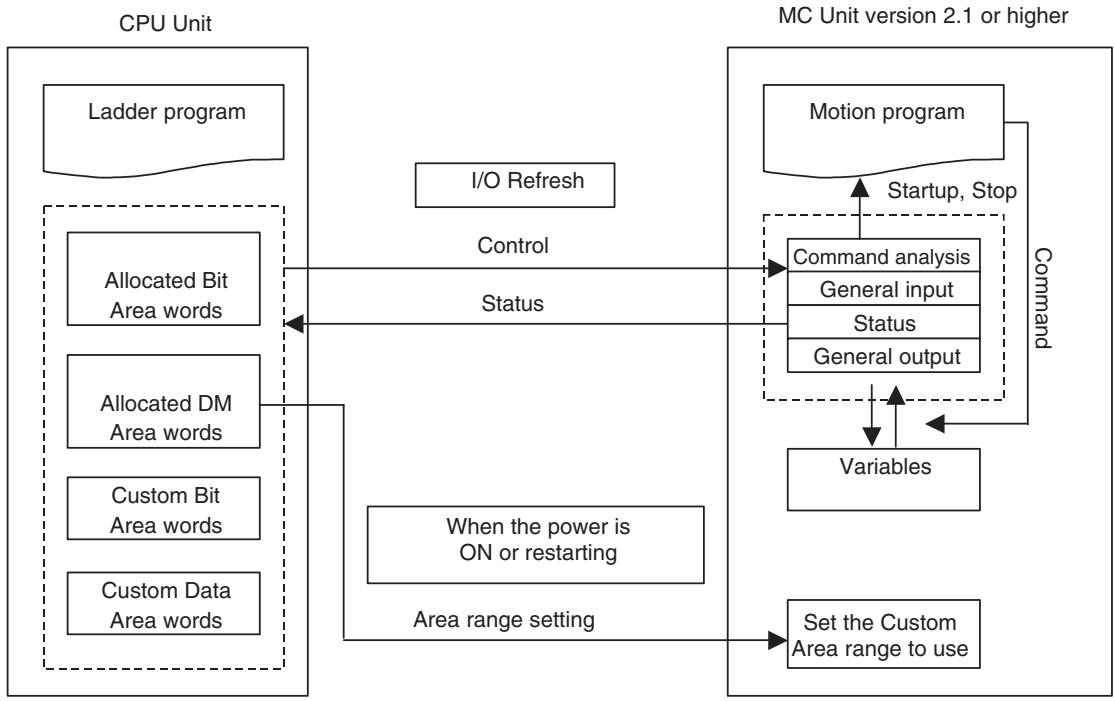
The function for exchanging data in the Custom I/O Area has been enhanced with MC Units with unit version 2.1, as shown in the following table.
For details on previous specifications, refer to SECTION 7 PC Interface Area.
| No. | Classification | MC Unit Variable Area | Area size | |
| Previous version(Unit Ver. 2.0) | Present version(Unit Ver. 2.1) | |||
| 1 | General I/O A | IW0B00 to IW0B9F or OW0B00 to OW0B9F | The variable area and addresses can be allocated for the following variables. • System variables • Global general variables • Input variables | 0 to 160 words |
| 2 | General I/O B | IW0BA0 to IW0C3F or OW0BA0 to OW0C3F | 0 to 160 words | |
| 3 | General I/O C | IW0C40 to IW0CDF or OW0C40 to OW0CDF | 0 to 160 words | |
| 4 | General I/O D | IW0CE0 to IW0D7F or OW0CE0 to OW0D7F | Output variables • Position data • Task variable | 0 to 160 words |
| 5 | General I/O E | IW0D80 to IW0E1F or OW0D80 to OW0E1F | 0 to 160 words | |
| 6 | General I/O F | IW0E20 to IW0EBF or OW0E20 to OW0EBF | 0 to 160 words | |
| 7 | General I/O G | IW0EC0 to IW0F5F or OW0EC0 to OW0F5F | 0 to 160 words | |
| 8 | General I/O H | IW0F60 to IW0FFF or OW0F60 to OW0FFF | 0 to 160 words | |
Guide to CS1W-MCH71 Version Upgrade
Function Upgrades from Unit Version 3.0 to 3.1
Restarting after Restoration
| Previous versions (Unit Ver. 3.0 and earlier) | Current version (Unit Ver. 3.1) |
| After data has been restored from the CPU Unit's flash memory, the Unit must be restarted by cycling the CPU Unit's power supply. | After data has been restored from the CPU Unit's flash memory, the Unit is restarted using a bit between A50100 and A50115 in the Auxiliary Area of the CPU Unit. For details, refer to 7-1 Overview. |
Expanded Bank Switching for Interpolation Acceleration/Deceleration Times
| Previous versions (Unit Ver. 3.0 and earlier) | Current version (Unit Ver. 3.1) |
| The acceleration time and deceleration time used for interpolation operations cannot be set separately. | The acceleration time and deceleration time used for interpolation operations can be set separately. P00004, bit 13: Bank switching method selection 0: Select the same bank for acceleration and deceleration (same as for version 3.0). 1: Select different banks for the acceleration time and deceleration time. Parameters P00M11 to P00M15 are used to set acceleration times, and P00M16 to P00M20 are used to set deceleration times. For details, refer to 6-1 Basic Information. |
Internal Overrides
| Previous versions (Unit Ver. 3.0 and earlier) | Current version (Unit Ver. 3.1) |
| There is a function for changing the axis feed rate from a ladder program, but not from a motion program. | The feed rate when the following commands are executed can be changed from a motion program. Commands for which an override can be speci-fied from the motion program: MOVE Rapid feed rate DATUM Origin return feed rate MOVEI Rapid feed rate, external position-ing rate MOVET Rapid feed rate The actual speed is as follows: Actual speed = Axis feed rate x (Axis override + Internal override) For details, refer to 6-1 Basic Information. |
Connecting to SMART STEP Junior Servo Drivers
| Previous versions (Unit Ver. 3.0 and earlier) | Current version (Unit Ver. 3.1) |
| Cannot be connected. | Can be connected. |
Backup and Restore Functions
| Previous versions (Unit Ver. 3.0 and earlier) | Current version (Unit Ver. 3.1) |
| The origin compensation value when an absolute encoder is used is backed up using the CPU Unit's easy backup function. | Origin compensation values can be backed up even with CX-Motion-MCH version 2.1. For details, refer to Section 11 Backup and Restore in the CX-Motion-MCH Operation Manual (Cat. No. W448). |
Program and CAM Data Read Protection
| Previous versions (Unit Ver. 3.0 and earlier) | Current version (Unit Ver. 3.1) |
| There is no program and CAM data read protection. | The CX-Motion-MCH version 2.1 read protection function (password setting), can be used to prevent third-parties from reading program and CAM data. For details, refer to Section 12 Read Protection in the CX-Motion-MCH Operation Manual (Cat. No. W448). |
Function Upgrades from Unit Version 2.0 to 3.0
Expanded Allocations in Custom I/O Area
| Previous version (Unit Ver. 2.0) | Present version (Unit Ver. 3.0) |
| Only the I/O variable area determined in advance could be allocated to the Cus-tom I/O Area. | In addition to the I/O variables, system variables, global general variables, position data, and task variables for user-specified addresses can be allocated to the Custom I/O Area. |
Digital Input Values Changed to Improve Noise Resistance
| Previous version (Unit Ver. 2.0) | Current version (Unit Ver. 3.0) |
| Rated input voltage: 24 VDC ±10% Rated input current: 4.06 to 4.48 mA ON voltage: 9.5 V min. OFF voltage: 4.5 V max. | Rated input voltage: 24 VDC ±10% Rated input current: 4.02 to 4.52 mA ON voltage: 14 V min. OFF voltage: 6V max. (Any sensors that were previous used can still be used.) |
Parameter Added for Faster Unit Cycle and Communications Cycle Time
| Previous version (Unit Ver. 2.0) | Current version (Unit Ver. 3.0) |
| Unit cycle [us] = (115.0 × Number of axes) + (165 × Number of motion tasks × Number of parallel branches) + (0.3 × Number of general allocation words) + 350.0 | Unit cycle [us] = (85 × Number of axes) + (120 × Number of motion tasks × Number of parallel branches) + (0.3 × number of general allocation words) + 200 |
| Communications cycle [us] = ((Number of allocated Units + Number of retries) × 133.3+26.2) × 1.1 | Communications cycle [us] = ((Number of allocated Unit + Number of retries) × 102.7 + 19.2) × 1.1 Use the following parameter to switch the performance. • Parameter number: P00004 • Bit: 09 (previously reserved) 0: Initial value. Performance is the same as before. 1: Selects faster performance. |
Signed Master Axis MOVELINK Command
| Previous version (Unit Ver. 2.0) | Current version (Unit Ver. 3.0) |
| The main axis input sign is ignored and data is read as an absolute travel distance. | The main axis input sign is evaluated and the data is read as a signed travel distance. This function enables the main axis to use the feedback speed of an axis traveling at low speed. |
Indirect Writing of Position Data
| Previous version (Unit Ver. 2.0) | Current version (Unit Ver. 3.0) |
| Position data can be indirectly read but cannot be indirectly written. | Position data can be both read and written indirectly. Example: Indirect Writing @PL0000 = 1234; “1234” will be assigned as the contents of the address set in PL0000. This function does not affect previous functionality. |
Program Start Bit Status
| Previous version (Unit Ver. 2.0) | Current version (Unit Ver. 3.0) |
| An operation completed bit alone cannot be used to detect the end of programs with processing times that are shorter than the Unit cycle time. | The start bit ON/OFF status in the CPU Unit is output to the task status bit. Example for Axis 1: • n+17 bit 06: start bit (Reserved in previous unit versions.) 0: Start bit from CPU Unit OFF 1: Start bit from CPU Unit ON The end of the relevant program can be detected if this bit is ON and the operation completed bit is ON. |
Re-execution of WAIT Command
| Previous version (Unit Ver. 2.0) | Current version (Unit Ver. 3.0) |
| If the program is stopped while WAIT command execution is in effect (i.e., when the deceleration stop bit is ON) and then re-started by setting the Start Mode to 1, the program is started from the next block after the WAIT command. | If the program is stopped while WAIT command execution is in effect (i.e., when the deceleration stop bit is ON) and then re-started by setting the Start Mode to 1, the WAIT command is re-exe-cuted. |
Main Power Status
| Previous version (Unit Ver. 2.0) | Current version (Unit Ver. 3.0) |
| The main power status (ON/OFF) is written to a system variable. | The main power status (ON/OFF) is written to both a system variable and a status bit for each axis. Example for Axis 1: • x+32 bit 12: Main power ON bit (reserved in previous unit versions) 0: Main power OFF 1: Main power ON The servo can be effectively locked from the CPU Unit after confirming that this bit is ON. |
Servo Driver Status
| Previous version (Unit Ver. 2.0) | Current version (Unit Ver. 3.0) |
| The Servo Driver warning and alarm codes are stored in the error log. The Servo status (torque limit, limit inputs, etc.) is output to system variables (SW021C and SW021D for axis 1.) | In addition to the functionality supported in previous unit versions, Servo Driver warning codes, alarm codes, and status (torque limit, limit inputs, etc.) are also output to the following output variables that were reserved in previous unit versions. OW0210: Axis 1 Warning code/alarm code OW0211: Axis 1 Status (same as SW021C) OW0212: Axis 1 Status (same as SW021D) to OW026D: Axis 32 Warning code/alarm code OW026E: Axis 32 Status (Same as SW07EC) OW026F: Axis 32 Status (Same as SW07ED) |
Compliance with RoHS Directive
| Previous version (Unit Ver. 2.0) | Current version (Unit Ver. 3.0) | ||
| Lead was included in the cream solder used to mount chip components, in the flow solder used in assembly, and in thread solder. | As shown below, lead is not used. There is no change in specifications (including outer appearance) resulting from this change. | ||
| Solder type | Main components | Solder type | Main components |
| Cream solder | Tin and lead | Cream solder | (1) Tin, silver, indium, and bismuth (2) Tin, silver, and copper |
| Flow solder | Tin and lead | ||
| Thread solder | Tin and lead | Flow solder | (1) Tin and copper (2) Tin, silver, and copper |
| Thread solder | Tin, silver, and copper | ||
| Note: Either 1 or 2 shown above is used. | |||
| There is no mark indicating compliance with the RoHS Directive. | The RoHS compliance mark is displayed. | ||
Increased Precision of CAMBOX Command
| Previous version (Unit Ver. 2.0) | Current version (Unit Ver. 3.0) |
| If the slave axis CAM table is switched during continuous master axis travel, part of the slave axis travel is eliminated when the CAM table is switched. Example: CAMBOX [J01]1 [J02]10000 K10000 Q8 B0;Cam 1 CAMBOX [J01]2 [J02]10000 K10000 Q8 B0;Cam 2 CAMBOX [J01]3 [J02]10000 K10000 Q8 B0;Cam 3 Slave axis displacement 0 Slave axis speed 0 This amount of travel is eliminated. | The slave axis will travel the set amount, even if the slave axis CAM table is switched during continuous master axis travel. Example: CAMBOX [J01]1 [J02]10000 K10000 Q8 B0;Cam 1 CAMBOX [J01]2 [J02]10000 K10000 Q8 B0;Cam 2 CAMBOX [J01]3 [J02]10000 K10000 Q8 B0;Cam3 Slave axis displacement 0 Slave axis speed 0 This amount of travel is eliminated. |
The following functions can be used with CX-Motion-MCH version 2.0 or higher (available from August 2006).
Data Tracing
| Previous version (Unit Ver. 2.0) | Current version (Unit Ver. 3.0) |
| Data tracing is not supported. | A data tracing function is provided that can simultaneously collect a maximum of 32 data items. This function does not affect previous functionality. Previously reserved parameters and variables are used to set and reference data trace conditions and status. |
Debugging
| Previous version (Unit Ver. 2.0) | Current version (Unit Ver. 3.0) |
| Breakpoints cannot be set. | Debugging is supported using breakpoints that are set using the Support Tool, and debugging is supported for direct operation. These functions do not affect previous functionality, but the following bit has been added to the Unit status to indicate that debugging is being executed from the Support Tool. • CIO n+15, bit 09: Operating mode (Reserved in previous unit versions.) 0: Normal mode 1: Support Tool mode (debugging) |
Zones
| Previous version (Unit Ver. 2.0) | Current version (Unit Ver. 3.0) |
| Zones are not supported. | A maximum of 32 zone bits are available. Zone bit: A bit that turns ON when any variable is within the set range, and turns OFF when the variable is outside of the range. The previous function and the new function can be switched using the following parameter. • Parameter number: P00011 (Reserved in previous unit versions.) • Setting: 0 to 32 0: Default. Same as previous function. 1 to 32: Use zone bits 1 to 32. Parameters and variables that were previously reserved are used to set zone upper and lower limits. |
Setting the Number of Parallel Branches for Each Task
| Previous version (Unit Ver. 2.0) | Current version (Unit Ver. 3.0) |
| The number of branches and the number of commands that can be executed are the same for each task. | The number of branches and the number of instructions that can be executed can be set individually for each task, enabling fine adjustment of the Unit cycle. The previous function and the new function can be switched using the following parameter. • Parameter number: P00004 • Bit 11 (Reserved in previous unit versions.) 0: Default. Same as previous function. 1: Individually set the number of branches and the number of commands that can be executed in each task. Previously reserved parameters are used to set the number of parallel branches individually for each task. |
Present Position Preset to Establish Origin
| Previous version (Unit Ver. 2.0) | Current version (Unit Ver. 3.0) |
| The origin is not established when the present position is set to the preset value. | The origin is established when the present position is set to the preset value. The previous function and the new function can be switched using the following parameter. • Parameter number: P00004 • Bit 12 (Reserved in previous unit versions.) 0: Default. Same as previous function. 1: Origin established for preset. |
Servo OFF for Deceleration Stop Signal
| Previous version (Unit Ver. 2.0) | Current version (Unit Ver. 3.0) |
| When the deceleration stop signal for the Unit turns ON, all axes are decelerated to a stop. | When the deceleration stop signal for the Unit turns ON, the servo can be turned OFF for all axes. The operation for servo OFF is set in the Servo Driver parameters. The previous function and the new function can be switched using the following parameter. • Parameter number: P00004 • Bit 10 (Reserved in previous unit versions.) 0: Default. Same as previous function. 1: Servo OFF |
Function Improvements for Unit Version 2.0
Jogging
| Previous versions | Current version (Unit Ver. 2.0) |
| The JOG feed direction is set or reversed as follows: • Use the JOG/STEP Direction Bit to specify the feed direction. • Turn ON the JOG Bit. • To reverse the feed direction, turn OFF the JOG Bit. • After the axis is stopped, reverse the JOG/STEP Direction Bit. • Turn ON the JOG Bit. The feed direction will be reversed. | As shown below, a setting for reverse operation has been added. • Use the JOG/STEP Direction Bit to spec-ify the feed direction. • Turn ON the JOG Bit. • The feed direction is reversed by reversing the JOG/STEP Direction Bit even while the JOG Bit still ON. Use the following parameter to switch the previous function and the new one. • Parameter number: P00004 • Bit: 05 (previously reserved) 0: Initial value. Same as previous func-tion. 1: Selects new function. |
Communications Levels
| Previous versions | Current version (Unit Ver. 2.0 or later) |
| The MC Unit supported communications on up to three levels. | The MC Unit supports communications on up to eight levels, according to the eight levels supported by the CPU Unit. The CPU Unit supports eight levels with unit version 2.0 or later. |
Communications Cycle and Unit Cycle
| Previous versions | Current version (Unit Ver. 2.0 or later) |
| The MC Unit communications cycle and unit cycle times are as follows: Communications cycle: 1 ms, 2 ms, 4 ms Unit cycle: 1 ms, 2 ms, 4 ms, 8 ms | • Supporting a communications cycle of 3 ms enable more precise performance. Communications cycle: 1 ms, 2 ms, 3 ms, 4 ms Unit cycle: 1 ms, 2 ms, 3 ms, 4 ms, 6 ms, 8 ms • Use the following parameter to switch the previous function and the new one. Parameter number: P00004 Bit: 03 (previously reserved) 0: Initial value. Same as previous function. 1: Enables use of 3 ms. |
LATCH Command Processing Time
| Previous versions | Current version (Unit Ver. 2.0 or later) |
| The time from when the LATCH command is executed until the external latch signal is detected is as follows: • When latch signals are received at any position: 105 to 232 ms • When only latch signals in a specified position range are received: 105 to 232 ms | As shown below, performance is improved in cases where latch signals are received at any position. • When latch signals are received at any position: 3 to 24 ms • When only latch signals in a specified position range are received: 105 to 232 ms |
Latch Status Refresh Time
| Previous versions | Current version (Unit Ver. 2.0 or later) |
| After a LATCH command is executed, the time from when the latch signal is input until it is reflected in the system variable (the variable showing latch completion) is 14.5 to 85.5 ms. | The performance has been improved as follows:7.5 to 37.5 ms |
Using Interpolation Commands during Pass Operation
| Previous versions | Current version (Unit Ver. 2.0 or later) |
| To execute pass operation from a stopped axis, two interpolation commands are required for the initial operation. Example: PASSMODE; MOVEL [J01]100 F10000; MOVEL [J02]400 F10000; WHILE #MW0000==0; INC MOVEL [J02]100 F1000; WEND; : | To execute pass operation from a stopped axis, only one interpolation command is required. Example: : PASSMODE; WHILE #MW0000==0; INC MOVEL [J02]100 F1000; WEND; : |
Acceleration/Deceleration Times during Pass Operation
| Previous versions | Current version (Unit Ver. 2.0 or later) | |
| Changing the acceleration/ deceleration times during pass operation was complex at any time. It was necessary to use the PARALLEL command to execute parallel processing. | The acceleration/deceleration times can be changed during pass operation. As shown below, switching is made easy by using a newly added parameter. MOVEL [J01]1000 F1000 ← The time set in bank 2 #W0A00 = 2; is used for passing to the next position. MOVEL [J01]5000 F1000 The following ten newly added parameters use part of the task parameter area that was previously reserved. Setting range: 0 to 60,000 (ms) | |
| Number | Name | |
| P00M11 | Interpolation feed acceleration/ deceleration time, Bank 1 | |
| : | : | |
| P00M20 | Interpolation feed acceleration/ deceleration time, Bank 10 | |
Deceleration Time during Pass Operation
| Previous versions | Current version (Unit Ver. 2.0 or later) |
| The interpolation feed deceleration time is used to decelerate to a stop during pass operation. Example: Pass Mode Selection, P00M06 = 0 Interpolation feed acceleration time Ta = P0MM02 Interpolation feed deceleration time Td = P00M03 Program PASSMODE; INC MOVEL [J01]1000 F100000; INC MOVEL [J01]1000 F100000; END; | The interpolation time used during pass operation (the interpolation feed acceleration time or the interpolation feed deceleration time) is used to decelerate to a stop during pass operation. Example: Pass Mode Selection, P00M06 = 0 Interpolation feed acceleration time Ta = P0MM02 Interpolation feed deceleration time Td = P00M03 Program PASSMODE; INC MOVEL [J01]1000 F100000; INC MOVEL [J01]1000 F10O000; END; |
| Speed Ta Ta Td Time | To stop at the interpolation feed deceleration speed as previously, add STOP-MODE before the final interpolation command as shown below. PASSMODE; INC MOVEL [J01]1000 F100000; STOPMODE; INC MOVEL [J01]1000 F100000; END; |
Torque to Position Control Switching
| Previous versions | Current version (Unit Ver. 2.0 or later) |
| Switching from torque control to position control using the TORQUR command is executed when the axis feedback speed reaches 0. | • Switching from torque control to position control using the TORQUR command is executed by switching to position control when the axis feedback speed reaches the speed specified in a parameter (specified by a percentage of the rated speed). • The following newly added parameter uses part of the axis parameter area that was previously reserved. |
| Number Name | |
| P3AA09 Position control switching speed | |
| Setting range: 0 to 32,767 (0.01%) |
Speed to Position Control Switching
| Previous versions | Current version (Unit Ver. 2.0 or later) |
| Switching from speed control to position control using the SPEEDDR command is executed when the axis feedback speed reaches 0. | • Switching from speed control to position control using the SPEEDDR command is executed when the axis feedback speed reaches the speed specified in a parameter (specified by a percentage of the rated speed). • The following newly added parameter uses part of the axis parameter area that was previously reserved. |
| Number Name | |
| P3AA09 Position control switching speed | |
| Setting range: 0 to 32,767 (0.01%) |
TABLE OF CONTENTS
PRECAUTIONS. xli
1 Intended Audience. xlii
2 General Precautions. xlii
3 Safety Precautions xlii
4 Application Precautions. xlv
5 Operating Environment Precautions xlv
6 Conformance to EC Directives xlv
SECTION 1 Features and System Configuration 1
1-1 Features 2
1-2 System Configuration 4
1-3 Basic Operations 6
1-4 Control System Configuration and Principles 11
1-5 Performance Specifications 12
1-6 Command List 18
1-7 Performance. 21
SECTION 2 Basic Procedures. 25
2-1 Basic Operation Flow 26
2-2 Overview of CX-Motion-MCH 28
SECTION 3 Installation and Wiring 31
3-1 Nomenclature and Functions 32
3-2 Installation 34
3-3 External I/O Circuitry 38
3-4 Wiring 42
3-5 Connecting MECHATROLINK Devices. 43
SECTION 4 MC Unit Internal Data Configuration and Setting. 55
4-1 Data Configuration 56
4-2 System Parameters. 58
4-3 Variables 105
4-4 Position Data 107
4-5 System Variables 111
4-6 I/O Variables 160
4-7 Present Position Preset. 190
4-8 Servo Parameter. 191
4-9 CAM Data 210
TABLE OF CONTENTS
SECTION 5
Data Transfer and Storage. 211
5-1 Data Transfer and Storage 212
5-2 IOWR Instruction to Transfer Data 221
5-3 IORD Instruction to Transfer Data 228
5-4 Saving Data 234
SECTION 6
Programming 239
6-1 Basic Information 240
6-2 Command Overview 286
6-3 Command Details 298
SECTION 7
PC Interface Area. 373
7-1 Overview 374
7-2 Operating Mode 382
7-3 Allocations for the CPU Unit 396
7-4 Interface Specifics 420
SECTION 8
Establishing the Origin. 531
8-1 Overview 532
8-2 Input Signals Required for Origin search 534
8-3 Origin Search Methods and Parameters 534
8-4Origin Search Operations 536
8-5 Absolute (ABS) Encoders 539
8-6 ABS Encoder Origin Setting 540
SECTION 9
Other Operations 545
9-1 Teaching 546
9-2 Debugging the Program 553
9-3 Coordinate System. 558
9-4 Backup and Restore Function 566
9-5 Servo Driver Status Output 569
9-6 Data Tracing 570
9-7 Zones 571
TABLE OF CONTENTS
SECTION 10
Program Example. 573
10-1 Program Example 574
10-2 Slave Modules 607
10-3 Others. 619
SECTION 11
Troubleshooting 627
11-1 Troubleshooting 628
11-2 Countermeasures 634
11-3 Error Indicators 638
11-4 Unit-related Alarm Codes 639
11-5 Motion Task-related Alarm Codes. 642
11-6 Axis-related Alarm Codes 648
11-7 MLK Device Alarm Codes 653
11-8 Servo DriverWarnings. 655
11-9 Error Log 656
SECTION 12
Maintenance and Inspection 659
12-1 Routine Inspection 660
Appendices
A Performance 663
B Main Parameter Settings when Connecting W-series Servo Driver with Built-in MECHATROLINK-II Communications 667
Revision History 671
About this Manual:
This manual describes the installation and operation of the CJ1W-MCH71 and CS1W-MCH71 Motion Control Units (MC Units) and includes the sections described below.
Please read this manual carefully and be sure you understand the information provided before attempting to install or operate the MC Unit. Be sure to read the precautions provided in the following section.
Precautions provides general precautions for using the Motion Control Unit, Programmable Controller, and related devices.
Section 1 introduces the features and system configuration of the CJ1W-MCH71 and CS1W-MCH71 Motion Control Units. It also describes product operating principles and provides product specifications.
Section 2 provides an overview of the basic procedures required to use the CJ1W-MCH71 and CS1W-MCH71 Motion Control Units.
Section 3 describes the names of Unit parts and how to install and wire the CJ1W-MCH71 and CS1WMCH71 Motion Control Units.
Section 4 describes the data configuration uses to set up, operate, and monitor the CJ1W-MCH71 and CS1W-MCH71 Motion Control Units and related devices.
Section 5 describes how to transfer data between the CPU Unit and the CJ1W-MCH71 and CS1W-MCH71 Motion Control Units and how data is stored.
Section 6 describes how to program CJ1W-MCH71 and CS1W-MCH71 Motion Control Units operation, including the program configuration and the specific commands used in programming.
Section 7 describes the interface area in the CPU Unit used to control and monitor the CJ1W-MCH71 and CS1W-MCH71 Motion Control Units.
Section 8 describes how to establish the origin in the positioning system.
Section 9 describes special operations for the CJ1W-MCH71 and CS1W-MCH71 Motion Control Units, including teaching, program debugging, coordinate systems, and backup functions.
Section 10 provides a programming example to demonstrate how the CJ1W-MCH71 and CS1WMCH71 Motion Control Units can be used.
Section 11 describes how to troubleshoot problems that may occur when using the CJ1W-MCH71 and CS1W-MCH71 Motion Control Units.
Section 12 describes the maintenance and inspection procedures required to keep the CJ1W-MCH71 and CS1W-MCH71 Motion Control Units in optimum condition.
The Appendix describes the performance of the Motion Control Units.
Registered Trademark
- MECHATROLINK is a registered trademark of the MECHATROLINK Members Association.
Read and Understand this Manual
Please read and understand this manual before using the product. Please consult your OMRON representative if you have any questions or comments.
Warranty and Limitations of Liability
WARRANTY
OMRON's exclusive warranty is that the products are free from defects in materials and workmanship for a period of one year (or other period if specified) from date of sale by OMRON.
OMRON MAKES NO WARRANTY OR REPRESENTATION, EXPRESS OR IMPLIED, REGARDING NONINFRINGEMENT, MERCHANTABILITY, OR FITNESS FOR PARTICULAR PURPOSE OF THE PRODUCTS. ANY BUYER OR USER ACKNOWLEDGES THAT THE BUYER OR USER ALONE HAS DETERMINED THAT THE PRODUCTS WILL SUITABLY MEET THE REQUIREMENTS OF THEIR INTENDED USE. OMRON DISCLAIMS ALL OTHER WARRANTYES, EXPRESS OR IMPLIED.
LIMITATIONS OF LIABILITY
OMRON SHALL NOT BE RESPONSIBLE FOR SPECIAL, INDIRECT, OR CONSEQUENTIAL DAMAGES, LOSS OF PROFITS OR COMMERCIAL LOSS IN ANY WAY CONNECTED WITH THE PRODUCTS, WHETHER SUCH CLAIM IS BASED ON CONTRACT, WARRANTY, NEGLIGENCE, OR STRICT LIABILITY.
In no event shall the responsibility of OMRON for any act exceed the individual price of the product on which liability is asserted.
IN NO EVENT SHALL OMRON BE RESPONSIBLE FOR WARRANTY, REPAIR, OR OTHER CLAIMS REGARDING THE PRODUCTS UNLESS OMRON'S ANALYSIS CONFIRMS THAT THE PRODUCTS WERE PROPERLY HANDLED, STORED, INSTALLED, AND MAINTAINED AND NOT SUBJECT TO CONTAMINATION, ABUSE, MISUSE, OR INAPPROPRIATE MODIFICATION OR REPAIR.
Application Considerations
| SUITABILITY FOR USE |
| OMRON shall not be responsible for conformity with any standards, codes, or regulations that apply to the combination of products in the customer's application or use of the products. |
| At the customer's request, OMRON will provide applicable third party certification documents identifying ratings and limitations of use that apply to the products. This information by itself is not sufficient for a complete determination of the suitability of the products in combination with the end product, machine, system, or other application or use. |
| The following are some examples of applications for which particular attention must be given. This is not intended to be an exhaustive list of all possible uses of the products, nor is it intended to imply that the uses listed may be suitable for the products: · Outdoor use, uses involving potential chemical contamination or electrical interference, or conditions or uses not described in this manual. · Nuclear energy control systems, combustion systems, railroad systems, aviation systems, medical equipment, amusement machines, vehicles, safety equipment, and installations subject to separate industry or government regulations. · Systems, machines, and equipment that could present a risk to life or property. |
| Please know and observe all prohibitions of use applicable to the products. |
| NEVER USE THE PRODUCTS FOR AN APPLICATION INVOLVING SERIOUS RISK TO LIFE OR PROPERTY WITHOUT ENSURING THAT THE SYSTEM AS A WHOLE HAS BEEN DESIGNED TO ADDRESS THE RISKS, AND THAT THE OMRON PRODUCTS ARE PROPERLY RATED AND INSTALLED FOR THE INTENDED USE WITHIN THE OVERALL EQUIPMENT OR SYSTEM. |
| PROGRAMMABLE PRODUCTS |
| OMRON shall not be responsible for the user's programming of a programmable product, or any consequence thereof. |
Disclaimers
CHANGE IN SPECIFICATIONS
Product specifications and accessories may be changed at any time based on improvements and other reasons.
It is our practice to change model numbers when published ratings or features are changed, or when significant construction changes are made. However, some specifications of the products may be changed without any notice. When in doubt, special model numbers may be assigned to fix or establish key specifications for your application on your request. Please consult with your OMRON representative at any time to confirm actual specifications of purchased products.
DIMENSIONS AND WEIGHTS
Dimensions and weights are nominal and are not to be used for manufacturing purposes, even when tolerances are shown.
PERFORMANCE DATA
Performance data given in this manual is provided as a guide for the user in determining suitability and does not constitute a warranty. It may represent the result of OMRON's test conditions, and the users must correlate it to actual application requirements. Actual performance is subject to the OMRON Warranty and Limitations of Liability.
ERRORS AND OMISSIONS
The information in this manual has been carefully checked and is believed to be accurate; however, no responsibility is assumed for clerical, typographical, or proofreading errors, or omissions.
This section provides general precautions for using the CJ1W-MCH71 and CS1W-MCH71 Motion Control Units and related devices.
The information contained in this section is important for the safe and reliable application of the CJ1W-MCH71 or CS1W-MCH71 Motion Control Unit. You must read this section and understand the information contained before attempting to set up or operate a CJ1W-MCH71 or CS1W-MCH71 Motion Control Unit.
1 Intended Audience xlii
2 General Precautions xlii
3 Safety Precautions. xiii
4 Application Precautions xlv
5 Operating Environment Precautions xlv
6 Conformance to EC Directives xlv
6-1 Applicable Directives xlv
6-2 Concepts xlv
6-3 Conformance to EC Directives. xlvi
6-4 Installation within Control Panel xlv
1 Intended Audience
This manual is intended for the following personnel, who must also have knowledge of electrical systems (an electrical engineer or the equivalent).
- Personnel in charge of installing FA systems.
- Personnel in charge of designing FA systems.
- Personnel in charge of managing FA systems and facilities.
2 General Precautions
The user must operate the product according to the performance specifications described in the operation manuals.
Before using the product under conditions which are not described in the manual or applying the product to nuclear control systems, railroad systems, aviation systems, vehicles, combustion systems, medical equipment, amusement machines, safety equipment, and other systems, machines, and equipment that may have a serious influence on lives and property if used improperly, consult your OMRON representative.
Make sure that the ratings and performance characteristics of the product are sufficient for the systems, machines, and equipment, and be sure to provide the systems, machines, and equipment with double safety mechanisms.
This manual provides information for programming and operating the Unit. Be sure to read this manual before attempting to use the Unit and keep this manual close at hand for reference during operation.
WARNING
It is extremely important that a PLC and all PLC Units be used for the specified purpose and under the specified conditions, especially in applications that can directly or indirectly affect human life. You must consult with your OMRON representative before applying a PLC System to the above-mentioned applications.
3 Safety Precautions
| DANGER |
| Never attempt to disassemble any Units while power is being supplied. Doing so may result in serious electronic shock. |
| Never touch any of the terminals while power is being supplied. Doing so may result in serious electronic shock. |
| Provide safety measures in external circuits (i.e., not in the Programmable Controller or MC Unit) to ensure safety in the system if an abnormality occurs due to malfunction of the PLC or MC unit. Not providing sufficient safety measures may result in serious accidents. |
| • Emergency- stop circuits, interlock circuits, limit circuits, and similar safety measures must be provided in external control circuits. • The PLC will turn OFF all outputs when its self-diagnosis function detects any error or when a severe failure alarm (FALS) instruction is executed. As a countermeasure for such errors, external safety measures must be provided to ensure safety in the system. • The PLC or MC Unit outputs may remain ON or OFF due to deposits on or burning of the output relays, or destruction of the output transistors. As a countermeasure for such problems, external safety measures must be provided to ensure safety in the system. • When the 24-VDC (service power supply to the PLC) is overloaded or short-circuited, the voltage may drop result in the outputs being turned OFF. As a countermeasure for such problems, external safety measures must be provided to ensure safety in the system. • Provide safety measures in external circuits to ensure safety in system if an abnormality occurs due to malfunction of MC Unit connectors. |
| WARNING | |
| Execute online edit only after confirming that the cycle time extension will not cause any adverse effects. Some input signals may not be read if the cycle time is extended. | ! |
| Confirm the safety of the destination node before transferring program to the node or changing the contents of I/O memory. Doing either of these without confirming safety may result in injury. | ! |
| Do not save data into the flash memory during memory operation or while the motor is running. Otherwise, unexpected operation may be caused. | ! |
| Do not reverse the polarity of the 24-V power supply. The polarity must be correct. Otherwise, the motor may start running unexpectedly and may not stop. | ! |
| When positioning is performed using Teaching function, positioning specification in the motion program must be [Absolute specification]. If [Incremental specification] is specified, positioning will be executed at the different point from where Teaching conducted. | ! |
4 Application Precautions
Observe the following precautions when using the MC Unit or the PLC.
-
Install external breakers and take other safety measures against short-circuiting in external wiring. Insufficient safety measures against short-circuiting may result in burning.
-
Always turn off after power supply to the Unit before attempting any of the following. Not turning OFF the power supply may result in malfunction or electric shock.
-
Mounting or dismounting the MC Unit or any other unit.
- Assembling the Units.
- Setting Rotary switches.
- Connecting Cables or wiring the system.
-
Connecting or disconnecting the connectors.
-
Confirming that no adverse effect will occur in the system before attempting any of the following. Not doing so may result in an unexpected operation.
-
Changing the operation mode of the PLC (including the setting of the startup operating mode).
- Changing the present value of any word or any set value in memory.
-
Force-setting /force-resetting any bit in memory.
-
Always connect to a ground of 100 or less when installing the Units. Not connecting to a ground of 100 or less may result in electric shock.
- Before touching the Unit, be sure to first touch a grounded metallic object in order to discharge any static built-up. Not doing so may result in malfunction or damage.
- Be sure that all the mounting screws, terminal screws, and cable connector screws are tightened to the torque specified in this manual. Incorrect tightening torque may result in malfunction.
- Tighten the mounting screws at the bottom of the Unit to a torque of 0.4 N·m. Incorrect tightening torque may result in malfunction.
- Perform wiring according to specified procedures.
- Leave the label attached to the Unit when wiring. Removing the label may result in malfunction if foreign matter enters the Unit.
- Remove the label after the completion of wiring to ensure proper heat dissipation. Leaving the label attached may result in malfunction.
- Check the pin numbers before wiring the connectors.
- Use crimp terminals for wiring. Do not connect bare stranded wires directly to terminals. Connection of bare stranded wires may result in burning.
- Be sure that the connectors, terminal blocks, I/O cables, cables between drivers, and other items with locking devices are properly locked into place. Improper locking may result in malfunction.
- Always use the power supply voltage specified in this manual. An incorrect voltage may result in malfunction or burning.
- Take appropriate measures to ensure that the specified power with the rated voltage and frequency is supplied. Be particularly careful in places where the power supply is unstable. An in correct power supply may result in malfunction.
- Do not apply voltages to the Input Units in excess of the rated input voltage. Excess voltage may result in burning.
- Do not apply voltages or connect loads to the Output Units in excess of the maximum switching capacity. Excess voltages or loads may result in burning.
- Check carefully all wiring and switch setting before turning ON the power supply. Incorrect wiring may result in burning.
- Separate the line ground terminal (LG) from the functional ground terminal (GR) on the Power Supply Unit before performing withstand voltage tests or insulation resistance tests. Not doing so may result in burning.
-
Do not place objects on the top of the cables or other wiring lines. Doing either of these may break the cables.
-
Do not pull on the cables or bend the cables beyond their natural limit. Doing so may break the cables.
- Do not turn off the power supply to the Unit while data is being written to flash memory. Doing so may cause problems with flash memory.
- Confirm that user program for proper execution before actually running it on the Unit. Not checking the program may result in an unexpected operation.
- Check the user program for proper execution before actually running it on the Unit.
Not checking the program may result in an unexpected operation.
- Resume operation only after transferring to the new MC Unit the contents of the parameters, position data, and other data required for resuming operation.
Not doing so may result in an unexpected operation. - Resume operation only after transferring to the new CPU Unit the contents of the DM Area, HR Area, and other data required for resuming operation. Not doing so may result in an unexpected operation.
- After transferring the system parameters, servo parameters, programs, position data, and CAM data to the MC Unit, be sure to save the data in flash memory within the MC Unit (using the data save command from the Support Tool or CPU Unit) before turning OFF the power supply to the Unit. Transferring the data to the MC Unit will simply save the data in the internal memory (S-RAM) of the MC Unit and this data will be cleared when the power supply to the Unit is turned OFF.
- After transferring the system parameter data to the MC Unit and saving the data to flash memory, be sure to reset the power supply to the unit or restart the Unit. Otherwise, some of the unit parameters and machine parameters will not be changed.
- The Machine lock function is enabled in each axis, for the effects on the operations with multiple axes such as interpolation operation be sure to machine lock all of relative axes in order to prevent the interference with other axes or devices.
- If axes are stopped during a synchronized operation, however, the synchronization of the master axis and slave axes positions will be cancelled. For that reason, be aware of the interference with other axes or devices when restarting up.
- When the load OFF status is occurred in the CPU Unit during manual operation such as JOG, which is performed by operating input variables from the MC Unit's program, the operation will be continued for one-cycle of the Unit. Using the WHILE command to repeat until given condition is satisfied, however, it continues to operate even load-OFF has occurred, be aware of the interference with other axes or devices.
- Do not attempt to take any Units apart, to repair any Units, or to modify any Units in anyway.
- The control distance will be longer if stopping at the maximum torque is changed to stopping by turning OFF the servo when a limit sensor is detected.
5 Operating Environment Precautions
- The installation must be conducted correctly.
-
Do not operate the control system in the following places.
-
Locations subject to direct sunlight
- Locations subject to temperatures or humidity outside the range specified in the specifications
- Locations subject to condensation as the result of severe changes in temperature.
- Locations subject to corrosive or flammable gases.
- Locations subject to dust (especially iron dust) or salts.
- Locations subject to exposure to water, oil, or chemicals.
-
Locations subject to shock or vibration.
-
Take appropriate and sufficient countermeasures when installing systems in the following locations. Inappropriate and insufficient measures may result in malfunction.
-
Locations subject to static electricity or other sources of noise.
- Locations subject to strong electromagnetic fields.
-
Locations subject to possible exposure to radioactivity.
-
Locations close to power supplies.
6 Conformance to EC Directives
6-1 Applicable Directives
EMC Directives
6-2 Concepts
EMC Directives
OMRON devices that comply with EC Directives also conform to the related EMC standards to that they can be more easily built into other devices or machines. The actual products have been checked for conformity to EMC standards (see the following note). The customer, however, must check whether the products conform to the standard in the system used by the customer.
EMC related performance of the OMRON devices that comply with EC Directives would vary depending on the configuration, wiring, and other conditions of the equipment or control panel in which the OMRON devices are installed.
The customer must, therefore, perform final checks to confirm that devices and the overall machine conform to EMC standards.
Note Applicable EMC (Electro-Magnetic Compatibility) standards are as follows:
EMS (Electro-Magnetic Susceptibility): EN61000-6-2,
EMI (Electro-Magnetic Interference): EN55011
EN55011 Radiated emission 10-m regulations
6-3 Conformance to EC Directives
The MC Unit complies with EC Directives. To ensure that the machine or device in which an MC Unit is used complies with EC Directives, the MC Unit must be installed as directed below:
- The MC Unit must be installed within a control panel.
Use a control panel like SA20-712 (Nitto Electronics) or similar to this. - Reinforced insulation or double insulation must be used for the DC power supplies used for the communications and I/O power supplies.
- MC Units complying with EC Directives also conform to the Common Emission Standard (EN50081-2). With regard to the radiated emission (10-m regulations), countermeasures will vary depending on the devices connected to the control panel, wiring, the configuration of the system, and other conditions. The customer must, therefore, perform final checks to confirm that devices and the overall machine conform to EC Directions.
6-4 Installation within Control Panel
Unnecessary clearance in cable inlet or outlet ports, operation panel mounting holes, or in the control panel door may cause electromagnetic wave leakage or interference. In this case, the product may fail to meet EC Directives. In order to prevent such interference, fill clearances in the control panel with conductive packing. (In places where conductive packing comes in contact with the control panel, ensure electrical conductivity by removing the paint coating or masking these parts when painting.)
SECTION 1
Features and System Configuration
The section introduces the features and system configuration of the CJ1W-MCH71 and CS1W-MCH71 Motion Control Units. It also describes product operating principles and provides product specifications.
1-1 Features 2
1-1-1 Overview. 2
1-1-2 Features. 3
1-2 System Configuration 4
1-2-1 System Configuration Example 4
1-2-2 Peripheral Devices (Models and Specifications) 5
1-3 Basic Operations 6
1-3-1 Applicable Machines 6
1-3-2 Position Control 6
1-3-3 Speed Control 8
1-3-4 Torque Control 8
1-3-5 Synchronous Control 8
1-3-6 Other Functions 10
1-4 Control System Configuration and Principles. 11
1-4-1 Control System Configuration 11
1-4-2 Control System Principles 12
1-4-3 Feedback Pulse 12
1-5 Performance Specifications. 12
1-5-1 General Specifications 12
1-5-2 Functions and Performance Specifications. 12
1-6 Command List. 18
1-7 Performance 21
1-1 Features
1-1-1 Overview
The MC Unit is a CS/CJ-series Motion Control Unit that can control thirty axes. An internal motion language programming is mounted, so that it can perform the advanced motion control operations.
1. Position Control
- Point-to-Point Control: With point-to-point (PTP) control, positioning is controlled independently for each axis. The pathway varies according to the travel distances, the feed rates, and so on.
- Continuous Path Control: With continuous path (CP) control, not only the start position and target position are controlled but also the path between those points. Functions such as linear interpolation, circular interpolation, helical circular interpolation, and traverse can be performed.
2. Speed Control
It makes the motor run at the specified speed, it also specifies the rate of speed change.
3. Torque Control
It generates specified Torque and specifies the rate of Torque change.
4. Synchronous Control
- Electronic Shaft: Functions the same as for the rolls connected to the gearbox with a gearshift.
- Electronic Cam: Functions the same as for the Machine CAM.
The MC Unit has been developed for use in simple positioning applications using servomotors. Applicable machines are as follows:
- Conveyor Systems: X/Y tables, palletizers/depalletzers, loaders/unloaders, etc. (Palletizers and depalletzers are devices used for loading goods onto pallets or for unloading them from pallets. Loaders and unloaded are devices that have shelves corresponding with the steps of a multi-step press and used for inserting or removing all the materials at one time.)
- Assembling Systems: Simple robots (including orthogonal robots), simple automated assembling machines (such as coil winding, polishing, hole punching), etc.
Note The MC Unit is not designed to perform the interpolation movement like a linear interpolation, a circular interpolation, or a helical circular interpolation with horizontal articulated robots or cylindrical robots, because it does not support coordinate conversions (cylindrical coordinate rotation function). The MC Unit can, however, perform PTP control with these robots.
1-1-2 Features
| Simple System Architecture | ·Independent control of multiple axes (Up to 30 physical axes; including virtual axes total is 32) ·Each axis can be set as either a physical or virtual axis. ·Additional unit is not required. |
| Easiest Information Management | ·High-speed channel with servo driver enables parameters' setting of servo driver, status monitoring. These functions are possible from the Support Tool or PT. ·Backup using Memory Card in CPU Unit. |
| Various motion controls ~Distributed control system~ | ·Besides CPU Unit of PLC, executes motion program for motion control. ·Regarding to motion task, up to 8 motion programs can be simultaneously executed. In each of these 8 programs, programs can be executed in parallel. |
| High-speed and flexibility | ·It is possible to realize variety of applications because of its availability for Synchronous Controls (Electric Shaft, Electronic Cam, Trailing Synchroniz- zation), Speed Control, Torque Control, and Position Control. ·The minimum length of servo communication cycle is 1 ms. ·It is possible to switch position, speed, and torque command during axis movement (there are few restrictions). ·The accurate controls of MC Unit and Servo driver or dispersion module are possible conducting a completely synchronized processing at fixed intervals. |
| Easy Debugging | ·Up to 32 data items can be traced simultaneously to enable debugging operations, such as checking the starting timing, to be easily performed using the support tool. ·Motion program consecutive operations, single-step operations, and breakpoint settings can be executed using the Support Tool. Note These functions can be used when CX-Motion-MCH version 2.0 or higher is used in combination with a Motion Control Unit of unit ver-sion 3.0 or later. |
| Combination of basic functions makes variety of synchronizations possible | ·Electronic Shaft function ·Electronic cam function (Time, position) ·Virtual axis function ·Axis movement function for superimposed axis, ADDAX ·Resist function (with present position hardware latch and window func- tion). ·Electronic link operation ·Trailing synchronization ·Target position change function ·Speed command ·Torque command ·Time-fixed positioning |
1-2 System Configuration
1-2-1 System Configuration Example
The MC Unit is adopted a high-speed communication pathway to simplify its wiring. It makes it possible to have up to 30 axes for controls.
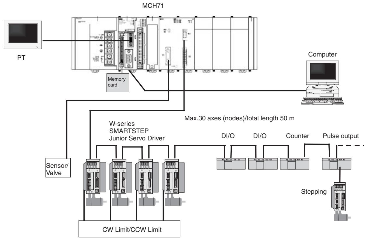
Note
(1) MECHATROLINK is a registered trademark of the MECHATROLINK Members Association.
(2) A W-series Servo Driver requires a YASKAWA MECHATROLINK-II I/F Unit (JUSP-NS115).
(3) Each of the products of the following version can be used. The version name is identified on the nameplate of each product. W-series servo driver: VER.39 or Later I/F Unit: VER **03 Later, or Equal
(4) When MECHATROLINK-II devices are connected up to 16 nodes (within 30m ) or 15 nodes (within 50m ), a repeater unit is not required. A repeater unit is required to connect MECHATROLINK-II devices more than the cases above.
(5) Always attach a Terminator to the last MECHATROLINK-II device on the network.
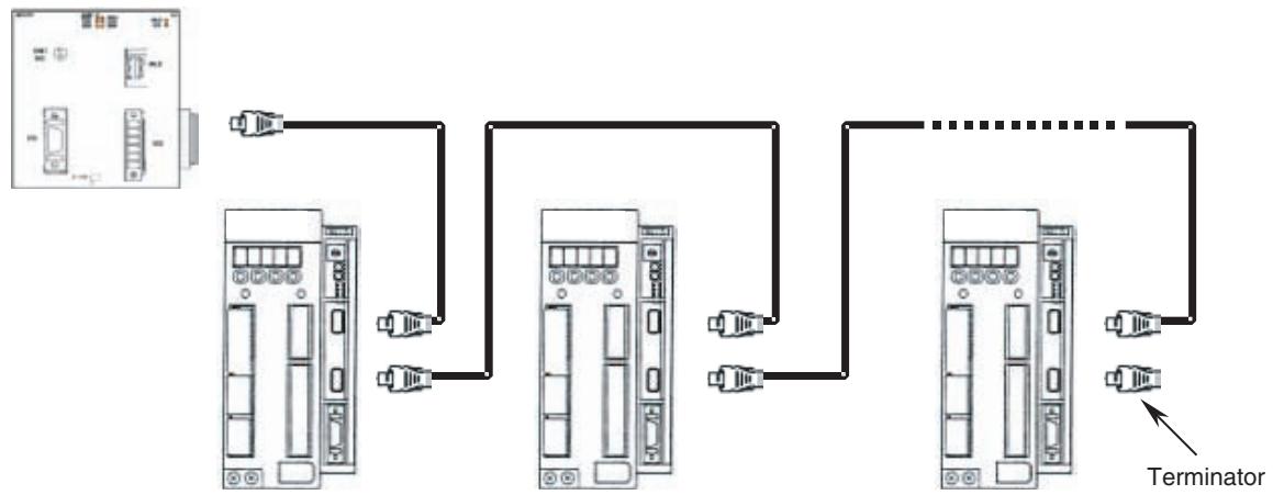
1-2-2 Peripheral Devices (Models and Specifications)
Support Tool
| Name | Remarks |
| CX-Motion-MCH Motion Control Support Tool | Included in CX-One FA Integrated Tool Package |
MECHATROLINK-II Devices and Cables
| Name | YASKAWA Model | OMRON Model | Specification Overview |
| MECHATROLINK-II Interface Unit | JUSP-NS115 | FNY-NS115 | For W-series Servo Driver |
| DC24V I/O Module | JEPMC-I02310 | FNY-I02310 | Input: 64 Output: 64 |
| Counter Module | JEPMC-PL2900 | FNY-PL2900 | Reversing Counter 2CH |
| Pulse Output module | JEPMC-PL2910 | FNY-PL2910 | Pulse Positioning |
| MECHATROLINK-II Cables for W-Series (With USB connectors and Ring Core) | JEPMC-W6003-A5 | FNY-W6003-A5 | 0.5 m |
| JEPMC-W6003-01 | FNY-W6003-01 | 1.0 m | |
| JEPMC-W6003-03 | FNY-W6003-03 | 3.0 m | |
| JEPMC-W6003-05 | FNY-W6003-05 | 5.0 m | |
| JEPMC-W6003-10 | FNY-W6003-10 | 10.0 m | |
| JEPMC-W6003-20 | FNY-W6003-20 | 20.0 m | |
| JEPMC-W6003-30 | FNY-W6003-30 | 30.0 m | |
| Terminator for MECHATROLINK-II | JEPMC-W6022 | FNY-W6022 | Terminating resistance (One Terminator is always required.) |
| Repeater for MECHATROLINK-II | JEPMC-REP2000 | FNY-REP2000 | Repeater |
Note MECHATROLINK-related products are manufactured by YASKAWA ELECTRIC CORPORATION.
We, OMRON, can take orders for them. When ordering them through OMRON, follow OMRON's ordering format. (The delivered products will be of YASKAWA BRAND.)
Ask our sales representatives about the price at when ordering them through OMRON.
1-3 Basic Operations
1-3-1 Applicable Machines
The MC Unit was developed for the purpose of motion control using servomotors.
Even though it depends on the machine accuracy, use an encoder, which is capable to detect 5-10 times more accurate than the machine accuracy.
Applicable machines
1,2,3...
- Assembling Systems
Simple robots, package machinery (horizontal type forming and vertical type forming), filling machine, grinder, drilling machinery, simple automated assembling machines, etc.
- Conveyor Systems
XY tables, palletizers/depalletzers, loaders/unloaders, etc.
Note
The MC Unit is not designed to perform linear interpolation, circular interpolation, or helical circular interpolation with horizontal articulated robots or cylindrical robots, because it does not support coordinate conversions. The MC Unit can, however, perform PTP control with these robots.
1-3-2 Position Control
The MC Unit offers the following three types of motion control:
- PTP Control
- CP Control (linear interpolation and circular interpolation)
- Interrupt Feeding
Control programs are created in the Motion language.
PTP Control
PTP control is used to control each axis (J01 and J02 axis) independently. Positioning time depends on the travel distance and speed of each axis.
Example: Moving from the origin to the J01-axis coordinate of 100 and J02-axis coordinate of 50 at the same speed.
Positioning is executed separately for each axis, so travel between the two points is carried out as shown in the diagram below:
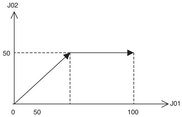
CP Control
CP Control is used to position by designing not only the starting point and the target point, but also the path between these two points. Both linear interpolation and circular interpolation are possible.
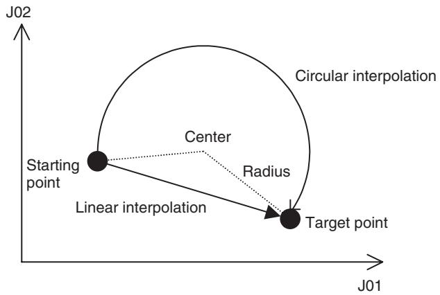
If [axis name 3] is added, helical interpolation is added to the linear interpolation. (The linear interpolation portion for multiple revolutions specifies the total travel distance.)
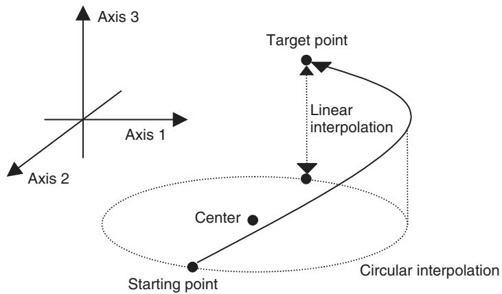
Interrupt Feeding
Interrupt feeding is used to perform position control for a fixed distance when the external signal is input.
Positioning with no interrupt signal is also possible.
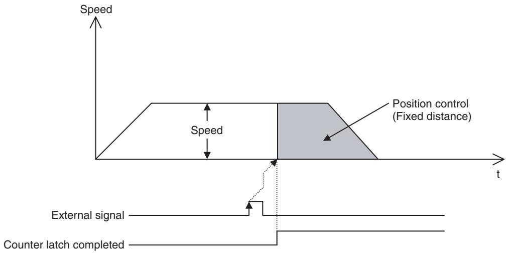
1-3-3 Speed Control
Make the motor run at a specified speed. It is also possible to specify the speed change rate.
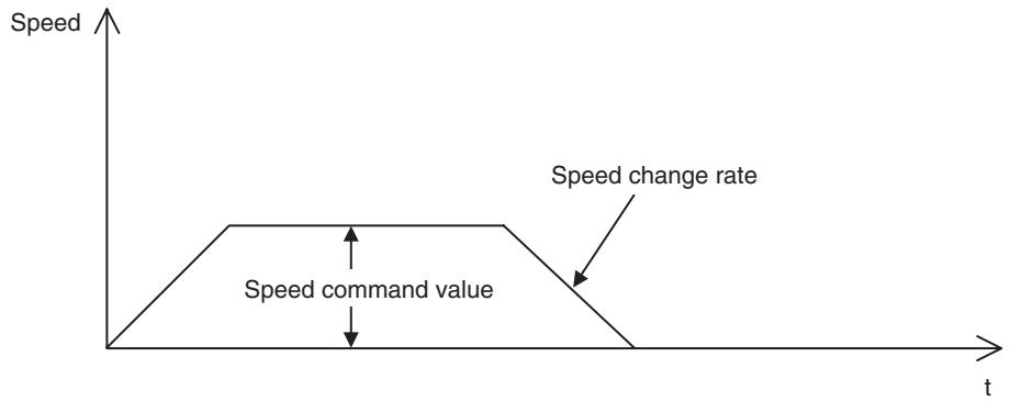
1-3-4 Torque Control
The designated torque can be generated. It is also possible to specify the torque change rate.
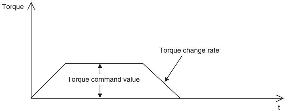
1-3-5 Synchronous Control
Listed below are the synchronous controls of this unit.
Electronic Shaft
Electronic cam
- Linking motions
- Trailing synchronization
Super position control
Each of above controls is programmed by motion language.
Electronic Shaft
This function can be used like rolls connected to gearbox with gearshift.
The slave axis synchronizes with the master axis at a specified ratio.
Electronic cam
This function can be used like the cam mechanism of a machine.
The slave axis synchronizes with the master axis according to the cam table.
Link operation
This function can be used like the link mechanism of a machine.
The slave axis synchronizes with the master axis following the specified acceleration, constant speed, and deceleration areas.
(In the diagram below, vertical and horizontal axes indicate speed and time respectively.)
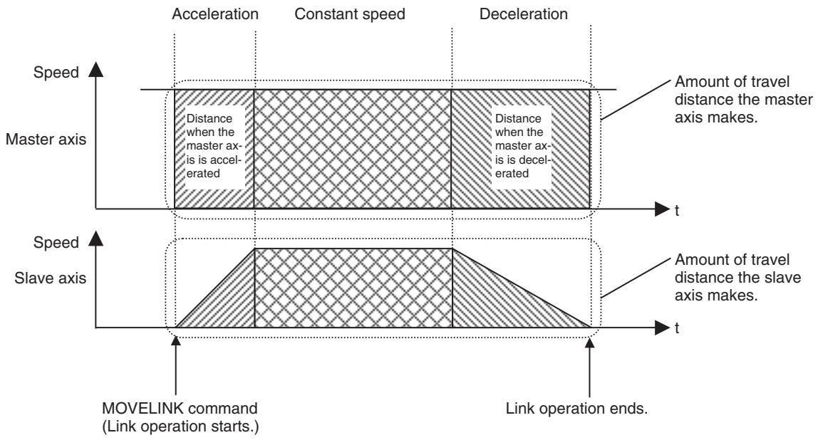
Trailing Synchronization
Trailing is started when the slave axis is standing by and the marker sensor is turned ON. Once it catches up with the master axis, synchronous operation is initiated.
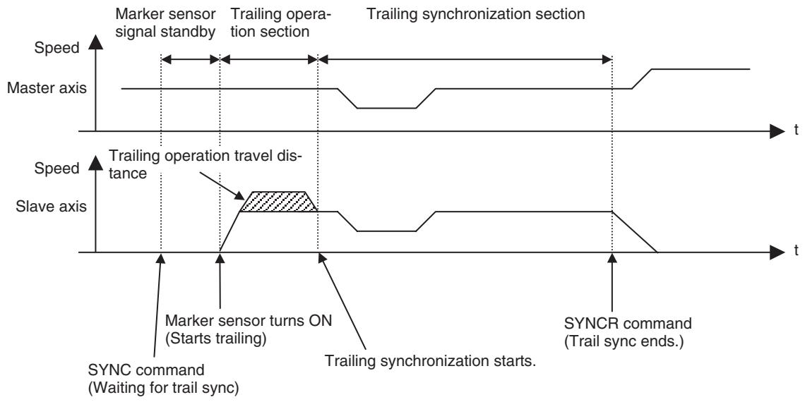
Travel Distance Superimpose
The travel distance of the master axis is superimposed on the slave axis. This function can be used like the differential gear of a machine.
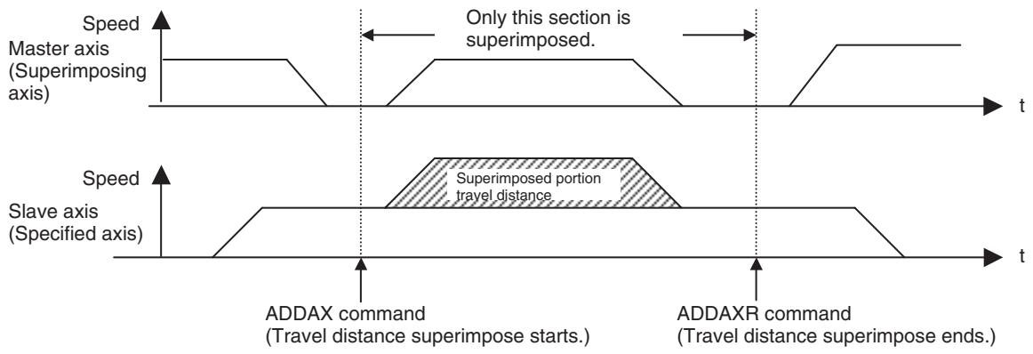
Data Tracing (Supported for unit version 3.0 and later.)
- Up to 32 data items can be traced simultaneously, with any bit (start bit, in-position bit, etc.) or data item (position command, speed command, etc.) taken as one item.
- A pre-trigger function is provided. As shown in the following diagram, when the condition is satisfied for the trigger signal that was set, this function can collect data prior to the condition being met.
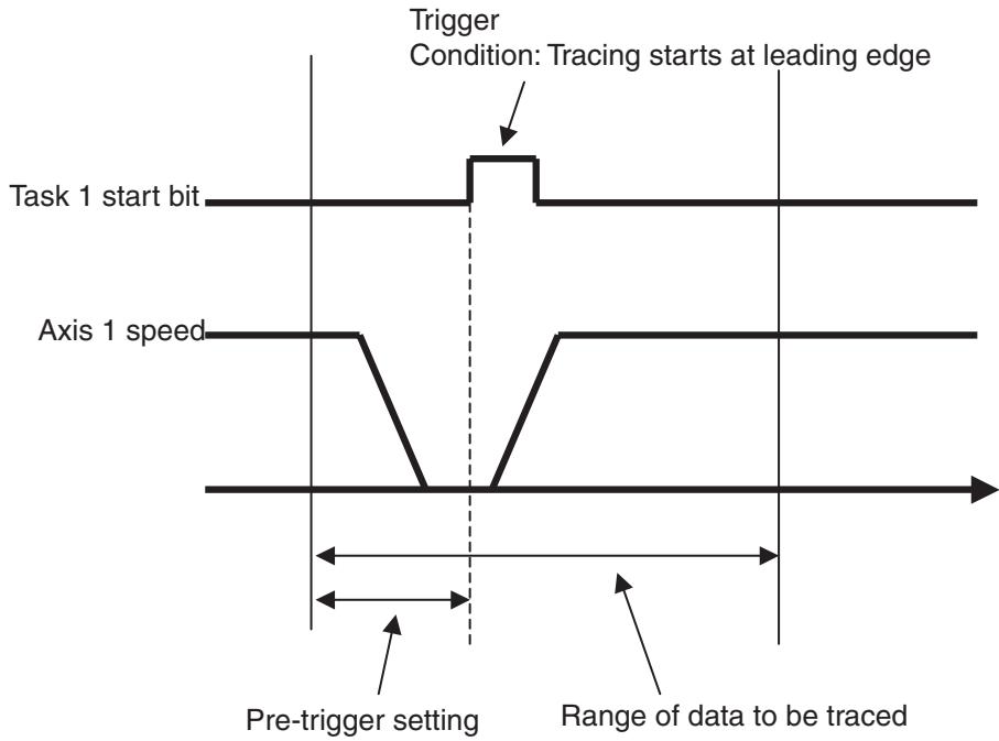
1-3-6 Other Functions
Origin Search
Establishes the origin for a specified axis.
Jogging
Starts and stops a specified axis at a specified speed.
Error Counter Reset
Forcibly resets the error counter to zero and stops axis operation after completing a deceleration command.
Present Position Preset
Changes the present position to specified position data.
Teaching
Obtains the present position to create position data.
| Override (Real-time Speed Change) | Changes the speed during PTP, linear interpolation, or circular interpolation operations. |
| Backlash Correction | Compensates errors caused by faulty meshing in the mechanical system. |
| Unlimited Feeding | Controls axes such as turntables and conveyors that are fed only in one direction unlimtimately. |
| Debugging | It is possible to execute just one line of a program through single block operation. It is also possible to run programs without operating the machine system through Machine Lock. |
| Data Storage | Backups and restores data using PLC memory cards. |
| Arithmetical Operation Command | Performs Simple arithmetic operation, Functions, and Logic Operations. |
| Zones (Supported For unit version 3.0 and later.) | ·A zone bit turns ON when any variable (including feedback present position, feedback speed, etc.) is within the set range, and OFF when outside of the set range. ·A maximum of 32 zones can be set. |
1-4 Control System Configuration and Principles
The servo system used by and the internal operations of the MC Unit are briefly described below.
1-4-1 Control System Configuration
Semi-closed Loop System
The MC unit uses the servo system called the semi-closed loop system.
This system is designed to detect actual machine travel distance for a command value using rotations of the motor and the detected value is fed back to the MC unit. The unit computes and compensates the error between the command value and actual travel distance to make it zero.

The semi-closed loop system is the mainstream in modern servo systems applied to positioning devices for industrial applications.
1-4-2 Control System Principles
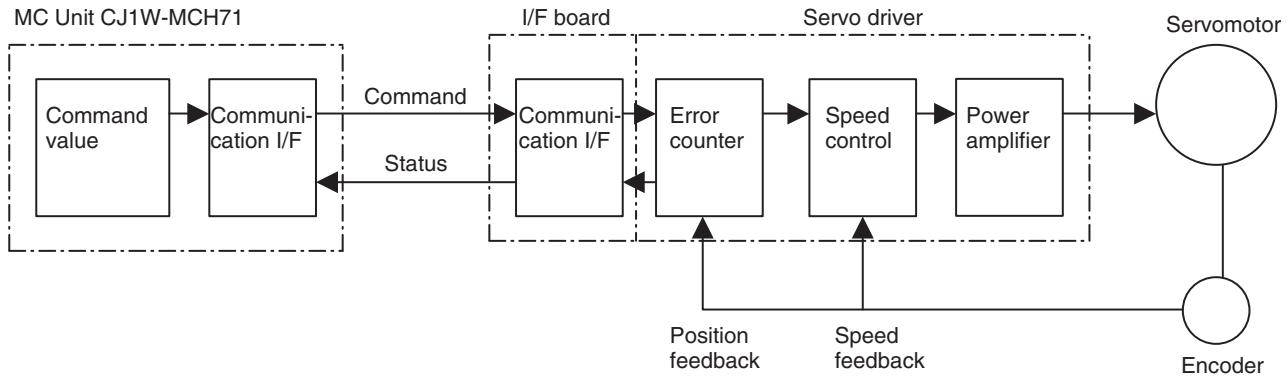
Internal Operations of the MC Unit
1-4-3 Feedback Pulse
Normal rotation/Counter rotation of a motor
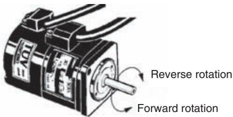
(CCW) is the forward rotation and (CW) is the reverse rotation when viewed from the output shaft side of the motor.
1-5 Performance Specifications
1-5-1 General Specifications
| Item | Specifications | |
| Model | CJ1W-MCH71 | CS1W-MCH71 |
| Power supply voltage | 5 VDC (from Backplane) | |
| 24 VDC (from external power supply) | ||
| Voltage fluctuation tolerance | 4.5 to 5.5 VDC (from Backplane) | 4.75 to 5.25 VDC (from Backplane) |
| 21.6 to 26.4 VDC (from external power supply) | ||
| Internal current consumption | 5 VDC 0.6 A max. | 5 VDC 0.8 A max. |
| 24 VDC 0.3 A max. | ||
| Weight (Connectors excluded) | 210 g max. | 300 g max. |
| Safety standards | UL, CSA, C-TICK, and EC compliant. | |
| Dimensions (mm) | 90 (H) × 79.8 (W) × 65 (D) (single) | 130 (H) × 35 (W) × 100.5 (D) (single) |
| Altitude | At 2,000 m elevation or lower. | |
Specifications other than those shown above conform to the general specifications for the SYSMAC CS/CJ series.
1-5-2 Functions and Performance Specifications
| Item | Specifications | |
| Model | CJ1W-MCH71 | CS1W-MCH71 |
| Applicable PLC | CJ-series PLCs with CPU Units with unit version 2.0 or later | CS-series PLCs with CPU Units with lot number 030418 or later (Refer to Note on page 16.) |
| Item | Specifications | ||
| Type of Unit | CPU Bus Unit | ||
| Mounting | CPU unit or expansion rack | ||
| Number of Units | One CJ1W-MCH71 Motion Control Unit requires the space of three standard Unit. (Refer to Note (1) on page 16.) | One slot | |
| Method for data transfer with CPU Unit | CIO Area for CPU Bus Unit | Occupies the area for 1 unit (25 words) | |
| For units and tasks: 11 to 25 words (Depending on the number of motion tasks) | |||
| DM Area for CPU Bus Unit | Occupies the area for 1 unit (100 words) | ||
| For units and tasks: 32 to 74 words (Depending on the number of motion tasks) | |||
| Custom Bit Area | For axes: 0-64 words (Depending on the greatest number of the axis used) | ||
| Custom Data Area | For axes: 0-128 words (Depending on the greatest number of the axis used) | ||
| Custom Data Area | For General I/O: 0-1280 words (Depending on setting) | ||
| Controlled Devices | MECHATROLINK-II below supported • W-series Servo Driver with built-in communications functions • W-series Servo Driver (OMRON) + Communications I/F Unit (YASKAWA) • Various I/O units (YASKAWA) • SMARTSTEP Junior Servo Drive Up to 30 nodes * When MECHATROLINK-II devices are connected up to 16 nodes (within 30 m) or 15 nodes (within 50m), a repeater unit is not required. A repeater unit is required to connect MECHATROLINK-II devices more than the cases described above. | ||
| Built-in program language | Dedicated motion control language | ||
| Control | Control method | MECHATROLINK-II • Position commands, Speed commands, Torque commands | |
| Number of controlled axes | 32 axes max. Physical axes/Virtual axes: 30 axes max. (Either can be selected for each axis) Dedicated for virtual axes: 2 axes | ||
| Operating modes | RUN mode, CPU mode, Tool mode/System (Depending on the tool) | ||
| Automatic/Manual Mode | Automatic mode: Executing built-in programs of MC Unit controls motion. Manual mode: Executing commands from CPU Unit (PC interface area) controls motion. Note The Automatic or Manual Mode is set according to the PC Interface area of the CPU Unit. | ||
| Control unit | Minimum setting unit | 1, 0.1, 0.01, 0.001, 0.0001 | |
| Units | mm, inch, deg, pulse | ||
| Maximum position command value | -2147483647 to 2147483647 pulses (signed 32-bit) Mode for unlimited axes feeding is possible. Example: With 16-bit encoder (65536 pulse/rev), Minimum setting unit: 0.001 mm, 10 mm/rev, the position command value range will be from -327679999 to 327679999 command units. | ||
| Item | Specifications | ||
| Control operations based on commands from the CPU Unit | Servo lock/unlock | Executes Servo driver lock or unlock | |
| Jogging | Executes continuous feeding independently for each axis, by means of speed set in system parameter x override. | ||
| STEP operation | Feeds a specified distance for a specified axis. | ||
| Origin search | Defines the machines origin according to the search method set in the system parameters. | ||
| Forced origin | Forcibly sets the present position to 0 to establish it as the origin. | ||
| Absolute origin setting | Sets the origin when an absolute encoder is used. Offset value: Signed 32-bit (pulses) | ||
| Error counter reset | Forcibly resets the error counter to 0. | ||
| Present position pre-set | Sets the present position to a user-specified value. | ||
| Machine lock | Prohibits the output of motion commands to the axes. | ||
| Single block | Executes the motion program one block at a time. | ||
| Auto/manual change | Switches between auto mode and manual mode. | ||
| Control Operations according to motion program | Positioning (PTP) | Executes positioning independently for each axis at the speed set in the system parameters. Simultaneous specification: 8 axes max. /block Simultaneous execution: 32 blocks max. /unit | |
| Linear interpolation | Executes linear interpolation for up to 8 axes simultaneously at the specified interpolation speed. Simultaneous specification: 8 axes max. /block Simultaneous execution: 32 blocks max. /system | ||
| Circular interpolation | Executes clockwise or counterclockwise circular interpolation for two axes at their specified interpolation speed. Simultaneous specification: 2 or 3 axes/block Simultaneous execution: 16 blocks max. /system | ||
| Origin search | Defines the machine origin according to the search method set in the system parameters. An offset can be specified for the position after the origin search. The absolute encoder can also execute origin search. | ||
| Interrupt feeding | By means of inputs to the servo driver, moves a specified axis for a specified travel distance to perform positioning. | ||
| Time-specified Positioning | Executes positioning with time specified. | ||
| Traverse function | Performs winding operation (traverse control) with two specified axes. | ||
| Electronic Cam, Single Axis | Execute cam operation according to the specified cam table data with reference to elapse of time. | ||
| Synchronous Electronic cam | Executes cam operation according to the specified cam table data with reference to the position of the specified axis. | ||
| Link operation | Executes link operation according to set conditions with reference to the position of the specified axis. | ||
| Electronic Shaft | Executes synchronous operation at a speed calculated with the speed of the specified axis and gear ratio. | ||
| Trailing synchronous operation | Executes trailing + synchronous operations with reference to the position of the spec-ified axis. | ||
| Speed command | Outputs speed commands to the specified axis. | ||
| Torque command | Outputs torque commands to the specified axis. | ||
| Acceleration /deceleration curve | Trapezoidal or S-shape | ||
| Acceleration/ deceleration time | Acceleration/ deceleration time | 60000 ms max. | |
| S-shape time constant | 30000 ms max. | ||
| External I/O | For high-speed servo communication bus | One port for MECHATROLINK-II | |
| Servo encoder | Incremental rotary encoder Absolute rotary encoder (Unlimited length ABS supported with some conditions) | ||
| I/O | Deceleration stop input (or servo-OFF stop): 1 pt General input: 2 pts General output: 2 pts | ||
| External power supply for I/O | 24 V | ||
| Feed rate | Rapid feed rate | 1 to 2147483647 [Command unit/min] | |
| Interpolation feed rate | 1 to 2147483647 [Command unit/min] | ||
| Override | Changes the operation speed by applying a given factor to the speed specified by the system parameters or the motion program. 0.00 to 327.67% (Setting unit: 0.01%, can be specified for each axis or task) | ||
| Internal override (supported for unit version 3.1 and later) | The feed rate of the following commands can be set by the motion program. Command Rate to which override is applied MOVE Rapid feed rate DATUM Origin return feed rate MOVEI Rapid feed rate, external positioning rate MOVET Rapid feed rate The actual feed rate is calculated using the following formula. Actual feed rate = Axis feed rate × (Axis override + Internal override) | ||
| Axis control | Backlash compensation | Compensates mechanical backlash (the mechanical play between driving and driven axes) with a value registered in advance. This function uses a parameter in the servo driver. | |
| In-position | This function is used whether a positioning is completed or not. This function uses a parameter in the servo driver. | ||
| Position loop gain | This is the position loop gain of the servo driver. This function uses a parameter in the servo driver. | ||
| Feed forward gain | The command values created in the MC Unit are multiplied by this feed forward gain. This function uses a parameter in the Servo Driver. | ||
| Program | Number of tasks | Motion task: 8 tasks max. | |
| Parallel branching in task | Motion task: 8 branches max. | ||
| Number of programs | 256 programs max. /unit The program Nos. used for programs are from 0000 to 0999. | ||
| Program numbers | 0000 to 0499: Main programs for motion tasks 0500 to 0999: Sub-programs for motion tasks | ||
| Program capacity | 2 Mbytes 8000 blocks max. /unit by motion program conversion. | ||
| Number of blocks | 800 blocks/program | ||
| Position data capacity | 10240 points/unit | ||
| Sub-program nesting | 5 levels max. | ||
| Start | Starts program operation from program (of another task) | ||
| Start mode | Motion task: Initial, continue, next | ||
| Deceleration stop | Motion task: Executes deceleration stop regardless of block | ||
| Block stop | Motion task: Executes deceleration stop at the end of the block currently being executed. | ||
| Single-block mode | Motion task: the program is executed one block at a time. | ||
| Breakpoints (supported for unit version 3.0 and later.) | Breakpoints can be set for any block using the Support Tool. When a breakpoint is set for a block, program execution will stop after that block has been executed. | ||
| Saving pro-gram data | MC Unit | Flash memory backup | |
| Zones (supported for unit version 3.0 and later.) | The zone bit turns ON when any variable (including feedback present position, feedback speed, etc.) is within the set range, and OFF when outside of the set range.A maximum of 32 zones can be set. | ||
| Data tracing (supported for unit version 3.0 and later.) | A maximum of two groups can be simultaneously traced, with 1 to 16 data items in each group.Note The items that can be traced are bits and data. These are each handled as a single item.The number of data samples that can be collected is 2,048 samples when 16 items are set for tracing to 32,768 when only 1 item is set for tracing. | ||
| Self-diagnostic function | Watchdog, FLASH-ROM check, RAM check, etc. | ||
| Error detection function | Deceleration stop input, unit number error, CPU Unit error, software limit over errors, etc. | ||
| Error log function | The error log is to be read from the CPU Unit by means of the IORD instructions as needed. | ||
| Alarm reset | Alarm reset | ||
| Program and CAM data read protection (supported for unit version 3.1 and later) | Third party access to program and CAM data can be restricted using the CX-Motion-MCH version 2.1 read protection function (password setting). | ||
Note
(1) To determine the number of MC Units that can be mounted under one CPU Unit, examine the followings:
- Maximum number of CPU Bus Units that can be allocated words in the CPU Unit being used
- The capacity of the power supply unit used for each rack (CPU Unit and Expansion Rack) and the current consumption of the units mounted on the racks. (Refer to the CPU Unit's operation manual for details on calculation methods.)
- Number of Units (CJ1W-MCH71 only) Each MC Unit requires the space of three standard Units. Although normally up to 10 CPU Bus Units can be connected in the CPU Rack or in each Expansion Rack, a maximum of only 3 MC Units can be mounted per Rack.
(2) The user must prepare the required power supply.
(3) The service life for the flash memory is 100,000 writing operations.
(4) The IOWR/IORD instructions can be used with CJ-series CPU Units with unit version 2.0 or later.
CS-series CPU Unit models are in the format CS1□-CPU□□H. The following conditions apply to certain CPU Units.
(1) CPU Units manufactured prior to January 7, 2002 (Lot No. 020107) do not support the IOWR/IORD instruction.
(2) Standard CPU Units manufactured after April 18, 2003 (Lot No. 030418) support the IOWR/IORD instruction.
The maximum command values and software limit values will be as shown in the following table corresponding to the position command decimal point position.
| Position command decimal point (Setting value for P5AA02) | Setting ranges |
| 1 (0) | -2147483648 to 2147483647 |
| 0.1 (1) | -214748364.8 to 214748364.7 |
| 0.01 (2) | -21474836.48 to 21474836.47 |
| 0.001 (3) | -2147483.648 to 2147483.647 |
| 0.0001 (4) | -214748.3648 to 214748.3647 |
The actual ranges that can be set may be smaller than those shown above depending on the pulse rate. The setting values must satisfy the following conditions:
With INC Specification:
Minimum value: -2147483648
Maximum value: 2147483647
With Limited Length Axis ABS Specification:
Minimum value: -(P5AA04 × P5AA06 × 2147483647) / (Encoder resolution × P5AA05)
Maximum value: (P5AA04 × P5AA06 × 2147483647)/(Encoder resolution × P5AA05)
With Unlimited Length Axis ABS Specification:
Minimum value: - (P5AA04 - 1)
Maximum value: P5AA04 - 1
P5AA04: Command unit/1 machine rotation
P5AA05: Gear ratio 1 (Motor rotation speed)
P5AA06: Gear ratio 2 (Machine rotation speed)
Example: With Limited length axis ABS specification, 1mm/rev, 16384 pulses/ rev with multiplication factor, and Minimum setting unit: 0.0001mm; The value will be from -131072000 to 131071999.
Additionally, the present positions that can be displayed on the Support Tool are to be within the range described in the above table.
The basic concept for immediate value:
There are integer and decimal immediate values; the applicable numeric value range for the MC Unit is shown below:
Integer: Numeric value without decimal point
Minimum value: -2147483648
Maximum value: 2147483647
Decimal: Numeric value with decimal point
Minimum value: -2147483648.
Maximum value: 2147483647.
Maximum number of decimals: 30 digits
Maximum number of digits excluding zero: 10 digits
(Negative definite: 2147483648, Positive definite: 2147483647)
| Number of decimals | 1 | 2 | 3 | 4 | 5 | 6 | 7 | 8 | 9 | 10 | 11 | 12 | 13 | 14 | 15 | 16 | 17 | 18 | 19 | 20 | 21 | 22 | 23 | 24 | 25 | 26 | 27 | 28 | 29 | 30 | |
| Negative definite | - | 0. | 0. | 0 | 0 | 0 | 0 | 0 | 0 | 0 | 0 | 0 | 0 | 0 | 0 | 0 | 0 | 0 | 0 | 0 | 0 | 2 | 1 | 4 | 7 | 4 | 8 | 3 | 6 | 4 | 8 |
| Positive definite | + | 0. | 0 | 0 | 0 | 0 | 0 | 0 | 0 | 0 | 0 | 0 | 0 | 0 | 0 | 0 | 0 | 0 | 0 | 0 | 0 | 2 | 1 | 4 | 7 | 4 | 8 | 3 | 6 | 4 | 7 |
| Maximum number of digits excluding 0 | |||||||||||||||||||||||||||||||
| Maximum number of decimals |
1-6 Command List
| Item | Contents | Page | |
| Operating modes | The following 2 modes are provided:Manual Modes: Operation according to commands from CPU Unit PC interface area.Automatic Mode: Operation according to commands in program. | 384510 | |
| Manual modeJOGSTEPOrigin Search | Jogging | Moves axes continuously by manual operation. | 476 |
| Deceleration stop(Axis) | Decelerates manual mode operations (Jogging, STEP, Origin search) and stop. | 472 | |
| STEP operation | Feeds a specified axis for a specified distance. | 480 | |
| Manual origin search | Searches for the machine origin (Possible with either Incremental or Absolute encoder) | 484 | |
| Manual origin return | Moves the axis to the origin in the reference coordinate system. | 489 | |
| Forced origin | Forcibly sets the present position to 0 to establish it as the origin. (In the absolute encoder system, only the present position of the MC Unit will be set to 0.) | 498 | |
| Present position pre-set | Sets the present position to a user-specified value. | 512 | |
| Absolute origin setting | Sets the origin for an absolute encoder. | 500 | |
| Automatic | Positioning (PTP) | Execute positioning independently for each axis at the specified speed or the speed set in the system parameters. | 298 |
| Positioning with linear interpolation | Executes linear interpolation at the specified interpolation feed rate for up to 8 axes simultaneously | 300 | |
| Positioning with circular interpolation | Executes clockwise or counterclockwise 2-axis circular interpolation at the specified interpolation feed rate. | 301 | |
| Positioning with helical circular interpolation | Executes clockwise or counterclockwise 2-axis circular interpolation and 1-axis linear interpolation (i.e., helical interpolation) at the specified interpolation feed rate. | 301 | |
| Origin search | Defines the machine origin according to the search method set in the system parameters. | 305 | |
| Interrupt feeding | Moves a specified axis for a specified distance when a general input is turned ON. | 308 | |
| Time-specified positioning | Executes positioning to a specified position with time specified. | 309 | |
| Target position change | Changes target position of an operating axis to a specified position. | 338 | |
| Internal Override | The feed rate of the following commands can be set by the motion program. Command Rate to which override is applied MOVE Rapid feed rate DATUM Origin return feed rate MOVEI Rapid feed rate, external positioning rate MOVET Rapid feed rate | 264 | |
| Traverse | Execute winding (traverse) function. | 311 | |
| Electronic Shaft function | Executes synchronous operation at a speed calculated with the speed of the specified master axis and a specified gear ratio. | 329 | |
| Electronic cam (Single axis) | Executes cam operation in a specified time period using a specified cam table. | 313 | |
| Electronic cam (Synchronous) | Synchronizes the slave axis to the master axis using cam table. | 320 | |
| Link operation | Synchronizes the slave axis to the master axis with specified acceleration, constant speed, and deceleration areas. | 316 | |
| Trailing synchronization | Slave axis starts trailing master axis at the rise of marker sensor when standing by. Once it catches up with master, synchronization starts. | 331 | |
| Travel distance superimpose | Superimposes travel distance of the master axis on the slave axis. It functions like the differential gear. | 332 | |
| Speed control | Rotates the motor at the specified speed. Speed change rate can also be specified. | 333 | |
| Torque control | Generates the specified torque. Torque change rate can also be specified. | 336 | |
| Virtual axis | This is an axis without an actual axis. It is used as a master axis to perform an ideal operation. | 282 | |
| Counter latch | The present position of an axis can be stored in hardware. | 345 | |
| Switching to Pass Mode | Changes to Pass Mode, in which operations are executed continuously with no deceleration stop. | 342 | |
| Dwell timer | Pauses positioning for a specified time. | 350 | |
| Arithmetic command | Performs arithmetic, function, and logic operations. | 361 363 365 | |
| Program start | Executes a program from the beginning block, resumes a program execution from the block where it was stopped, or resumes a program from the next block to the one where it was stopped. | 443 | |
| Single block | Executes programs one block at a time. | 458 | |
| Block stop | Stops program execution at the end of the block being executed. | 453 | |
| Automatic/ Man-ual mode | Backlash compensation | Compensates mechanical backlash (mechanical play between driving and driven axes) with the value registered in advance. (This is a function of the servo driver.) | 203 |
| Error counter reset | Forcibly resets the error counter to 0, and stops axis operation. (Enabled when no speed reference is given to the servo driver) | 493 | |
| Unlimited feed mode/ Unlimited present position display | Moves the axis with no limit. In this mode, data range for updating the present position can be specified. | 559 | |
| Present position pre-set | Changes the present position to the specified position data. | 56 | |
| Trapezoid/S-curve acceleration and deceleration | Either trapezoid or S-curve acceleration / deceleration can be specified for starting and stopping each axis. | 248 | |
| Axis alarm reset | Reset alarms occurring on axes. | 515 | |
| Unit alarm reset | Reset alarms occurring on units. | 420 | |
| Task alarm reset | Reset alarms occurring on tasks. | 465 | |
| Teaching | Creates position data for the specified axis. | 546 | |
| Deceleration stop (Task) | Decelerates each task to a stop. | 448 | |
| Override | Changes the operating speed by applying a specified percentage to the speed specified in the system parameters or programs. | 462 503 | |
| Servo-lock | Establishes the position loop and turns ON the RUN command output to the servo driver. | 474 | |
| Servo-unlock | Releases the position loop and turns OFF the RUN command output to the servo driver. | 474 | |
| Machine lock | Updates the position display without moving control axes. This is used for debugging program. | 506 | |
| Common | Data tracing | Traces data, such as command bits and feedback positions, using the Support Tool. | 570 |
| Debugging | Performs program operation, stopping, single-step operation, or stopping at any block from the Support Tool. | 553 | |
| Zones | A special bit is turned ON when any constant (e.g., feedback position) is within a set range without a special motion programming. | 571 | |
| Data transfer and storage | Data transfer | Transfer data from the CPU to the MC Unit and vice versa in a short period of time using IOWR/IORD instruction in the ladder program. | 56 221 |
| Data link | Custom data can be exchanged during I/O refresh by setting custom I/O area in the words allocated in the DM area of CPU Unit. | 378 402 | |
| Saving data | Stores programs, CAM data, parameters, position data, etc. in the MC Unit's flash memory. | 213 | |
| Backup and restore | Backs up or restores all the data in the MC Unit using the easy backup function and Support Software of the CPU Unit. | 566 | |
1-7 Performance
| Item | Performance data | Description |
| Unit cycle | Tm = 1, 2, 3, 4, 6, or 8 | This is the cycle in which motion tasks are executed in the MC Unit. The length of this cycle is determined by the number of axes, the number of motion tasks, the use of parallel execution, the number of allocated general-purpose words, and the communications cycle time. Tm will be equal to Ts or twice Ts. Refer to Appendix A Performance for details. |
| Communications cycle | Ts = 1, 2, 3, or 4 | This is the communications cycle for MECHA-TROLINK-II. The length of this cycle is determined by the number of allocated stations and the number of communications retries. Refer to Appendix A Performance for details. |
| Operation startup time and other performance | --- | Refer to Appendix A Performance for details. |
Processing Cycle of MC Unit
The MC Unit holds Control Cycle for the entire Unit and Communication Control Cycle.
The system software calculates each control cycle, and it operates using a Unit cycle to communications cycle ratio of 1:1 or 2:1.
Calculation methods for each control cycle are as follows:
- The Unit cycle is calculated.
- The Communication Cycle is calculated.
- The ratio between the Unit cycle and communications cycle is adjusted.
Calculation Method for Unit Cycle
The basic formula for calculating the Unit Cycle is shown below:
When P00004 bit 11 (number of parallel branches) is 0:
Unit cycle [ s] = (85 × Number of axes) + (120 × Number of motion tasks × Number of parallel branches) + (0.3 × Number of general allocated words) + 200.... (1)
- No. of axes: No. of axes allocated in [P1AA01: Physical axis setting] (Sum of virtual and actual axes)
- No. of Motion tasks: P00001 [No. of Motion tasks]
- No. of parallel branches: P00002 [No. of parallel branches]
- No. of general allocated words:
- No. of Allocated words to be used as general purpose I/O (Sum of inputs and outputs)
When P00004 bit 11 (number of parallel branches) is 1 (Supported for unit Ver. 3.0 and later):
Unit cycle [ s] = (85× Number of axes) ^+ (120× Number of parallel branches i ^+ (0.3× Number of general allocated words) ^+ 200.....(1)
ΣNumber of parallel branches i: Sum of the parallel branches set for individual task, P00M21
Example: If two tasks are used, and the task 1 P00M21 is 4 and the task 2 P00M21 is 2, then this value will be 2 + 4 = 6 .
Calculation Method for Communications Cycle
Note for P00003 [Unit Scan time]
When P00003 [Unit Scan time] is greater than the result of the formula (1), the formula (2) below is to be used.
$$ \text {U n i t C y c l e} [ \mu s ] = P 0 0 0 0 3 \times 1 0 0 0 - - (2) $$
Determining Unit Cycle
The Unit Cycle can be determined by rounding up the Unit Cycle [ s] that was found by the formula (1) or (2) to 1 ms, 2 ms, 3 ms, 4 ms, 6 ms, or 8 ms.
If the unit cycle time exceeds 8 ms, 8 ms is set.
Basic formula for calculating Communications Cycle is shown below:
$$ \begin{array}{l} \text {C o m m u n i c a t i o n s C y c l e} [ \mu s ] = ((\text {N o . o f a l l o c a t e d n o d e s} + \text {N o . o f R e t r i e s}) \times \ 1 0 2. 7 + 1 9. 2) \times 1. 1 - - (3) \end{array} $$
- No. of Allocated Node: No. of MECHATROLINK-II slaves (only physical axes) allocated in [P1AA01: Physical Axis Setting]
- No. of Retries: No. of retries specified in [P00009: MECHATROLINK No. of retrial nodes setting] (= 0 - 7) .
If the Communications cycle was less than 1ms, the formula (4) below is to be used.
$$ \text {C o m m u n i c a t i o n s c y c l e} [ \mu s ] = 1 0 0 0 - - (4) $$
Determining Communications Cycle
The Communications Cycle can be determined by rounding up the Communications Cycle [μs] that was found by the formula (3) or (4) to 1 ms, 2 ms, 3 ms, or 4 ms.
If the communications cycle time exceeds 4 ms, 4 ms is set.
Note
The formula used in this section applies when P00004 bit 09 is 1 for a CJ1W-MCH71 or CS1W-MCH71 Motion Control Unit with unit version 3.0 or later.
If the unit version is 2.0 or earlier, or the unit is version 3.0 or later but P00004 bit 09 is 0, the following formula applies.
Unit cycle [ s] = (115.0× Number of axes) ^+ (165.0× Number of motion tasks × Number of parallel branches) ^+ (0.3× Number of general allocated words) ^+ 350.0
Communications cycle [ s] = ((No. of allocated nodes + No. of Retries) × 133.3 + 26.2) × 1.1
Adjusting and Matching Unit Cycle and Communications Cycle
Determine the combination of the Unit Cycle and Communications Cycle using the following table:
The processing cycle time of the MC Unit can be found using the following table and the unit cycle and communications cycle times that have been calculated.
| Communications cycle | Unit cycle | |||||
| 1 ms | 2 ms | 3 ms | 4 ms*1 | 6 ms | 8 ms | |
| 1 ms | 1 ms:1 ms | 2 ms:1 ms | 3 ms:3 ms | 4 ms:2 ms | 6 ms:3 ms | 8 ms:4 ms |
| 2 ms | 2 ms:2 ms | 2 ms:2 ms | 3 ms:3 ms | 4 ms:2 ms | 6 ms:3 ms | 8 ms:4 ms |
| 3 ms*2 | 3 ms:3 ms | 3 ms:3 ms | 3 ms:3 ms | 4 ms:4 ms*3 | 6 ms:3 ms | 8 ms:4 ms |
| 4 ms | 4 ms:4 ms | 4 ms:4 ms | 4 ms:4 ms | 4 ms:4 ms | 8 ms:4 ms | 8 ms:4 ms |
Example: If the unit cycle time calculated under Calculation Method for Unit Cycle is 4 ms (1) and the communications cycle time calculated under Calculation Method for Communications Cycle is 3 ms (2), the MC Unit processing time, which combines the unit cycle time and communications cycle time, would be 4 ms:4 ms (*3).
SECTION 2
Basic Procedures
This section provides an overview of the basic procedures required to use the CJ1W-MCH71 and CS1W-MCH71 Motion Control Units.
2-1 Basic Operation Flow 26
2-2 Overview of CX-Motion-MCH 28
2-2-1 Functions 28
2-2-2 Installing and Uninstalling the Software 29
2-2-3 Operation Procedure 30
2-1 Basic Operation Flow
This Section gives an overview of the procedures required to use a MC Unit.
| OPR. | Operation Flow | Reference |
| Setup | START Install MC Unit Set Unit No. for MC Unit Connect Support Tool/CX-Programmer Connect MC Unit with External Input Devices Connect Servo Driver and Servomotor Connect Servo Driver and MC Unit | SECTION 3 Installation and Wiring 3-2 Installation 3-1 Nomenclature and Functions 3-4 Wiring |
| MC Unit Setting | Turn ON the Power to the PLC Create the I/O table of PLC Set MC Unit Allocation Area in PLC DM Area Power OFF and ON the PLC Use CX-Motion-MCH to set the system parameters, transfer them to MC Unit, and save them to flash Use CX-Motion-MCH to create motion programs and position data. Transfer them to MC Unit and save them to flash memory. Turn ON the power to the PLC or restart MC Unit to enable settings. | Users Manual for CS/CJ Series CPU Unit SECTION 7 PC Interface Area 7-3 Allocations for the CPU Unit SECTION 4 MC Unit Internal Data Configuration and Setting 4-2 System Parameters 4-4 Position Data SECTION 6 Programming |
| Trial OPR | A Use Manual Mode to execute Servo Lock Use Manual Mode to execute Jogging Use Manual Mode to execute Origin Search Switch to the Automatic Mode to start the motion program from PLC and operate the system. | SECTION 7 PC Interface Area 7-3 Allocations for the CPU Unit 7-4 Interface Specifics SECTION 8 Establishing the Ori-gin |
| Debug | Error Occurrence YES Check LED display on the MC Unit Read Alarm codes of MC Unit Eliminate the cause of error and clear it. | SECTION 11 Troubleshooting |
| Run | Run PLC to operate MC Unit | SECTION 10 Program Example |
| Maintenance | Maintenance and inspection • Replacing a MC Unit • Replacing Servo driver • Replacing the NS115 END | SECTION 12 Maintenance and Inspection |
Note For details of the procedure, refer to HELP of the Support Tool.
2-2 Overview of CX-Motion-MCH
The CX-Motion-MCH is a software package that can be used to set, create, and print various data required to control MC Units (such as system parameters, position data, motion task programs, and CAM data), transfer the data to and from the MC Unit, and monitor the operating status of the MC Unit.
The CX-Motion-MCH runs on Windows 98, Me, NT 4.0, 2000, XP, or Vista.
2-2-1 Functions
| Group | Function | Details |
| Editing projects | Create project | Used to create project files (*.mnh) |
| Add/delete Motion Control Unit | Used to add or delete MC Unit data in a project. | |
| Add/delete motion task | Used to add or delete motion tasks in a project. | |
| Add/delete axis | Used to add or delete axes in a project. | |
| Add/delete program | Used to add or delete programs in a project. | |
| Add/delete subprogram | Used to add or delete subprograms in a project | |
| Add/delete CAM table | Used to add or delete CAM tables in a project. | |
| Editing data | Edit system parame-ters | Used to edit system parameters (unit settings, tasks, and settings). |
| Edit servo parame-ters | Used to edit servo parameters. | |
| Edit motor parame-ters | Used to edit motor parameters. | |
| Edit position data | Used to edit position data. | |
| Edit program or sub-program | Used to edit programs or subprograms. | |
| Edit CAM table | Used to edit CAM tables. | |
| Edit symbol | Used to edit symbols. | |
| Saving and reading project files | Save project | Used to save data as a project file (*.mnh). |
| Read project | Used to read a project file (*.mnh). | |
| Importing and exporting data | Import | Used to import CX-Motion-MCH files, position data, programs, and CAM data. |
| Export | Used to export position data, programs, and CAM data. | |
| Backup and Restore | Backup and Restore | Backs up the origin compensation value. |
| Printing | Used to print various project data. | |
| Online | Initial setting | Used to setup CPU Unit or MC Unit. |
| Communications setting | Used to make settings for communications with the PLC. | |
| DownloadUploadCompare | Used to download, compare, or upload system parameters, servo parameters, position data, programs, and CAM data. | |
| Write to flash memory | Used to write RAM data inside the MC Unit to flash memory inside the MC Unit. | |
| Status monitor | Used to display the error information, program number in progress, and axes' present positions. | |
| General monitor | Used to display and change the MC Unit's variables, such as the system variables, global variables, input variables, output variables, position data, and task variables. | |
| Test Run | Used to execute the following operations: Servo locks, JOG operations, STEP operations, origin searches, origin returns, forced origins, setting an absolute origin, teaching, and resetting errors. | |
| Debug the Program | Used to debug the motion program. Motion programs can be debugged by setting breakpoints and by using single step execution. | |
| Data Trace | Data Trace | Used to set the trigger conditions and items. The results of the trace operation are displayed graphically. |
| Error | Error log | Used to display the error log. |
| Error information | Used to display error code and error name. | |
| Program and CAM data read protection | Program and CAM data read protection | Third party access to program and CAM data can be restricted using the read protection function (password setting). |
2-2-2 Installing and Uninstalling the Software
Required Software
The following software must be installed on the same computer to use the CXMotion-MCH.
- CX-Motion-MCH
- CX-Server (the communications driver, including the CX-Server Driver Management Tool)
CX-Motion-MCH Availability
The CX-Motion-MCH is available only as a component of the CX-One FA Integrated Tool Package.
Refer to the CX-One Ver.2.1 Setup Manual (W463, provided with the CX-One) for the
CX-One installation and uninstallation procedures.
| Cat. No. | Model | Manual name | Contents |
| W463 | CXONE-AL☐☐C-EV2 /AL☐☐D-EV2 | CX-One Ver.2.1 Setup Manual | An overview of the CX-One FA Integrated Tool Package and the CX-One installation procedure |
2-2-3 Operation Procedure
The overall procedure for using the CX-Motion-MCH is given below. Refer to the SYSMAC CX-Motion-MCH Operation Manual (W448) for details.
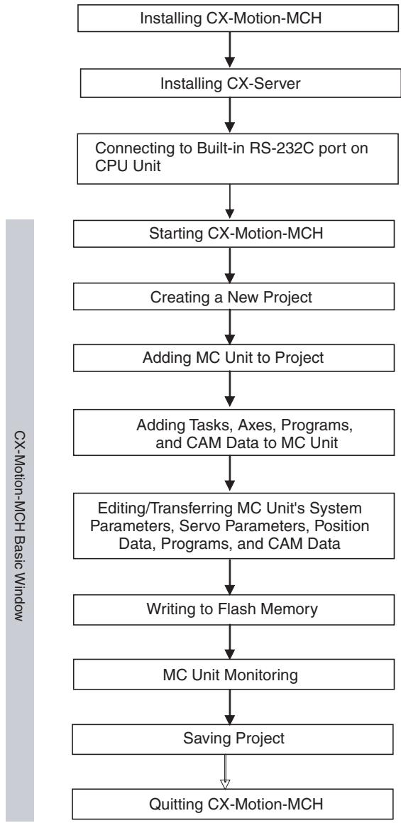
SECTION 3
Installation and Wiring
This section describes the names of Unit parts and how to install and wire the CJ1W-MCH71 and CS1W-MCH71 Motion Control Units.
3-1 Nomenclature and Functions 32
3-1-1 Nomenclature 32
3-1-2 Area Allocations 33
3-2 Installation 34
3-2-1 System Configuration Precautions 34
3-2-2 Mounting to the Backplane 35
3-2-3 Unit Handling Precautions 36
3-2-4 Dimensions 37
3-3 External I/O Circuitry 38
3-3-1 MECHATROLINK-II Connector 38
3-3-2 I/O Connectors 38
3-3-3 Wiring Connectors 39
3-3-4 I/O Circuits (CJ1W-MCH71 and CS1W-MCH71 Units Version 3.0 and Later) 40
3-3-5 I/O Circuits (CS1W-MCH71 Unit Version 2.0 and Earlier) 41
3-4 Wiring 42
3-4-1 Wiring Precautions 42
3-5 Connecting MECHATROLINK Devices. 43
3-5-1 Method of Connecting MECHATROLINK Devices 44
3-5-2 Servo Driver (W-series WT□□□) 44
3-5-3 24 VDC I/O Module 47
3-5-4 Counter Module, Pulse Output Module 51
3-1 Nomenclature and Functions
3-1-1 Nomenclature
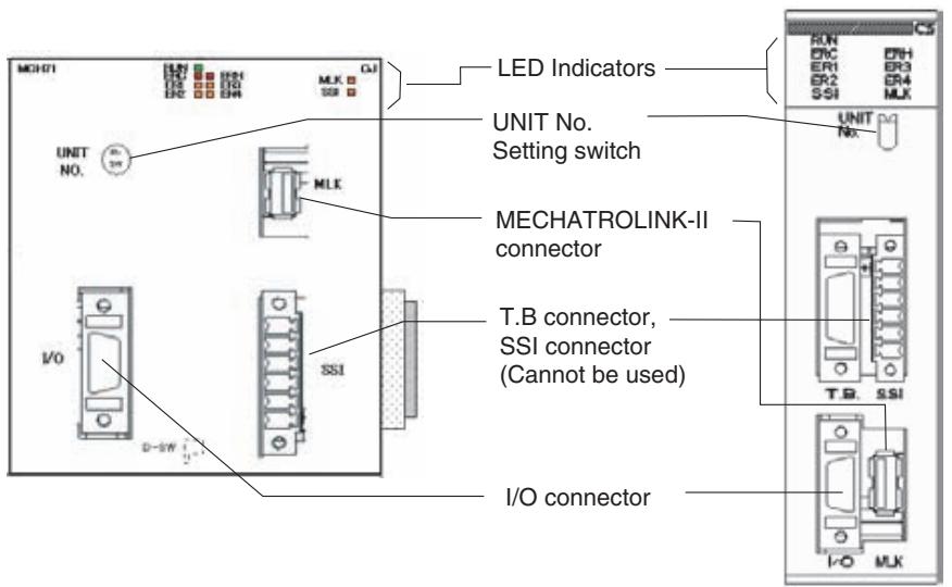
LED Indicators

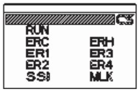
| Name | Color | Status | Content |
| RUN (RUN) | Green | Lit | Motion Control Unit is operating normally. |
| Not lit | Not recognized by PLC, or MC Unit is broken. | ||
| ERC (MC Unit Error) | Red | Lit | An error has occurred in the MC Unit. |
| Not lit | MC Unit is operating normally. | ||
| ERH (CPU Unit Error) | Red | Lit | An error has occurred in the CPU Unit. |
| Not lit | CPU Unit is operating normally. | ||
| ER1 (See note.) (Internal error status) | Yellow | Lit | An internal error has occurred. |
| Not lit | MC Unit is operating normally. | ||
| ER2 (See note.) (Internal error status) | Yellow | Lit | An internal error has occurred. |
| Not lit | MC Unit is operating normally. | ||
| ER3 (See note.) (Internal error status) | Yellow | Lit | An internal error has occurred. |
| Not lit | MC Unit is operating normally. | ||
| ER4 (See note.) (Internal error status) | Yellow | Lit | An internal error has occurred. |
| Not lit | MC Unit is operating normally. | ||
| SSI | Yellow | Lit | Not used. |
| Not lit | Not used. | ||
| MLK (MECHATROLINK-II) | Yellow | Lit | MLK is operating normally. |
| Not lit | An error has occurred in the MLK. |
Note When the ERC or ERH indicator is lit, these four indicators show the internal error status.
Unit Number Setting Switch
Several MC Units can be mounted on one CS/CJ series PLC.
It is necessary to set the unit numbers to identify these units when several MC or CPU Bus Units are mounted.
The rotary switch located on the forehead of MC Unit can set the unit numbers.
(Examples)

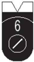
Unit Number: 6

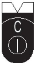
Unit Number: 12 (Hexadecimal)
The maximum of 16 MC Units can be mounted to one CS-series PLC, and a maximum of 12 MC Units can be mounted to one CJ-series PLC.
With a CJ-series PLC, up to 10 CPU Bus Units can normally be connected in the CPU Rack or in each Expansion Rack. Each CJ1W-MCH71 MC Unit, however, requires the space of three standard Units. Therefore, a maximum of only 3 MC Units plus one other CPU Bus Unit can be mounted per Rack.
The same unit number cannot be used twice in one PLC.

Caution Please check if the power is OFF when you start the settings.
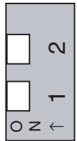
DIP Switch on the Back Panel of the Unit
These switches are inside the case and are used for special purposes like shipping inspection mode, etc. Therefore, do not operate them.
| 1 | 2 | Status |
| OFF | OFF | Normal operation |
| ON | OFF | Reserved for shipping inspection by OMRON (Do not set.) |
| OFF | ON | Reserved for shipping inspection by OMRON (Do not set.) |
| ON | ON | Reserved for shipping inspection by OMRON (Do not set.) (See note.) |
Note
If the power is turned ON under this setting, the MC Unit will be started after various user settings are set beck to their factory default values.
3-1-2 Area Allocations
Word Allocations Using Unit Numbers
CPU Bus Unit Allocated Bit Area
The bit and DM areas used by the MC Unit are allocated based on the unit number.
The bit area is allocated 25 words for each unit number starting from the word 1500.
| Unit number | Bit area | Unit number | Bit area |
| 0 | Words 1500-1524 | 8 | Words 1700-1724 |
| 1 | Words 1525-1549 | 9 | Words 1725-1749 |
| 2 | Words 1550-1574 | 10 | Words 1750-1774 |
| 3 | Words 1575-1599 | 11 | Words 1775-1799 |
| 4 | Words 1600-1624 | 12 | Words 1800-1824 |
| 5 | Words 1625-1649 | 13 | Words 1825-1849 |
| 6 | Words 1650-1674 | 14 | Words 1850-1874 |
| 7 | Words 1675-1699 | 15 | Words 1875-1899 |
CPU Bus Unit Allocated DM Area (DM Parameter Area)
The DM area is allocated 100 words for each unit number starting from the words D30000.
| Unit number | DM area | Unit number | DM area |
| 0 | Words 30000-30099 | 8 | Words 30800-30899 |
| 1 | Words 30100-30199 | 9 | Words 30900-30999 |
| 2 | Words 30200-30299 | 10 | Words 31000-31099 |
| 3 | Words 30300-30399 | 11 | Words 31100-31199 |
| 4 | Words 30400-30499 | 12 | Words 31200-31299 |
| 5 | Words 30500-30599 | 13 | Words 31300-31399 |
| 6 | Words 30600-30699 | 14 | Words 31400-31499 |
| 7 | Words 30700-30799 | 15 | Words 31500-31599 |
3-2 Installation
3-2-1 System Configuration Precautions
CJ1W-MCH71
- When using the IOWR/IORD instructions for the MC Unit, be sure that a version 2.0 or later CJ1-H/CJ1M CPU Unit is being used.
- I/O bit numbers of the CPU Bus Unit are allocated based on the setting of the Unit Number Setting Switch on the front panel of the Unit, not on the position in which the Unit has been connected.
- MC Units can be connected in either the CPU Rack or in Expansion Racks. A maximum of 3 MC Units can be connected per Rack. The total number of MC Units for the CPU Rack and all Expansion Racks is thus 12 MC Units maximum.
- When mounting a relay output unit on the very right of the MC Unit, make sure to use the surge absorber for the relay output line.
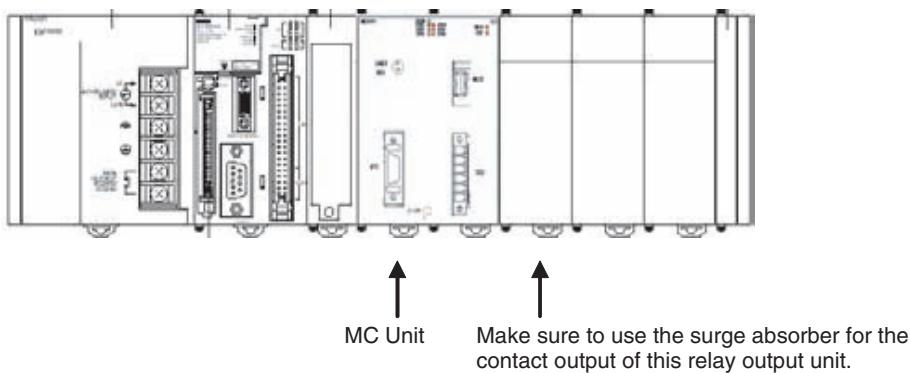
When MECHATROLINK-II devices are connected up to 16 nodes (within 30m ) or 15 nodes (within 50m ), no repeater unit is required. A repeater unit is required to connect MECHATROLINK-II devices more than the cases above.
CS1W-MCH71
- When using the IOWR/IORD instructions for the MC Unit, be sure that the CS1□-CPU□□H CPU Unit being used was manufactured on April 18, 2003 (Lot No. 030418) or later.
- The I/O words allocated to a CPU Bus Unit are based on the setting of the unit number setting switch on the front panel of the Unit, not on the position in which the Unit has been mounted.
-
The Units can be mounted to the CS1W-BC□□3 or CS1W-BC□□2 CPU Backplane, or the CS1W-BI□□3 or CS1W-BI□□2 Expansion Backplane.
-
When mounting a relay output unit on the very left of the MC Unit, make sure to use the surge absorber for the relay output line.
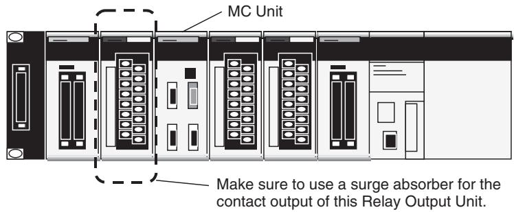
3-2-2 Mounting to the Backplane
CJ1W-MCH71
Use the following steps to mount or remove MC Units.
The Units that make up a CJ-series PLC can be connected simply by pressing the Units together and locking the sliders by moving them toward the back of the Units. The End Cover is connected in the same way to the Unit on the far right side of the PLC. Follow the procedure listed below to connect PLC components.
1,2,3... 1. The following diagram shows the connection of two Units that make up a CJ-series PLC. Join the Units so that the connectors fit exactly.
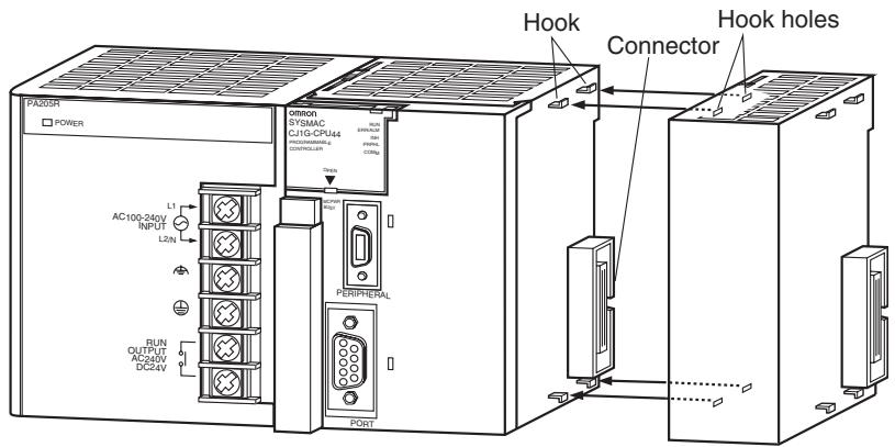
- The yellow sliders at the top and bottom of each Unit lock the Units together. Move the sliders toward the back of the Units as shown below until they click into place.
Note If the locking tabs are not secured properly, the CJ-series may not function properly. Be sure to slide the locking tabs until they are securely in place.
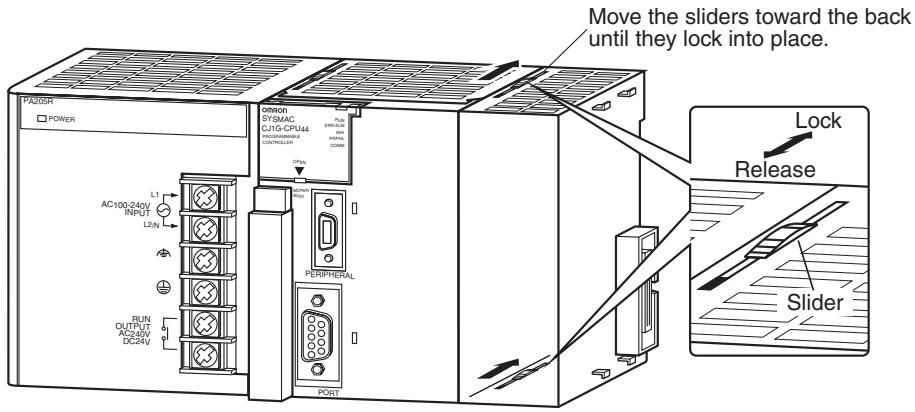
- Attach the End Cover to the Unit on the far right side of the Rack.
Note If the sliders are not locked securely, the MC Unit may not function properly. Be sure the sliders are completely locked into place.
To separate two Units, slide the sliders to the release position to release the lock.
CS1W-MCH71
1,2,3... 1. Hook the top mounting hooks on the base of the Unit on the Backplane.
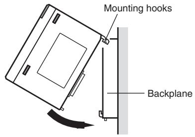
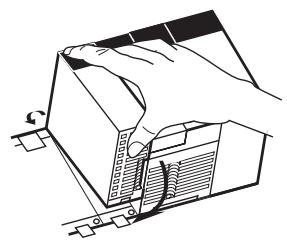
- Correctly insert the Unit into the Backplane connectors.
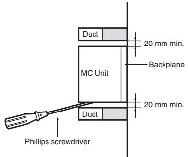
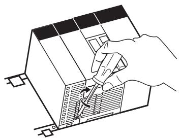
- Tighten the screw on the bottom of the Unit with a Phillips screwdriver. Leave enough space for ventilation and accessibility between the Unit and the ducts for attachment and removal of the Unit as shown in the figure below.
Note Tighten the bottom screw to a torque of 0.4 N·m.
To remove the Unit, loosen the screw on the bottom of the Unit with a Phillips driver, and then lift the Unit from below.

3-2-3 Unit Handling Precautions
Always turn OFF the CPU Unit before mounting or removing a MC Unit or connecting or disconnecting cables to or from the MC Unit.
Place the port connecting cables in a different duct from those for high-voltage lines or power lines to prevent the effects of electrical noise from these lines.
Do not remove the protective label from the top of the unit until wiring has been completed. This label prevents wire strands and other foreign matter from entering the Unit during wiring. Remove the label after wiring has been completed to allow air circulation needed for cooling.
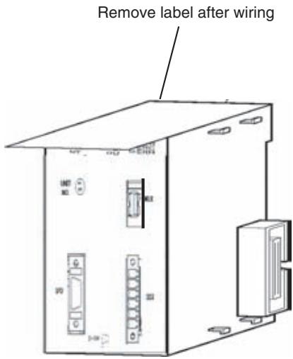
3-2-4 Dimensions
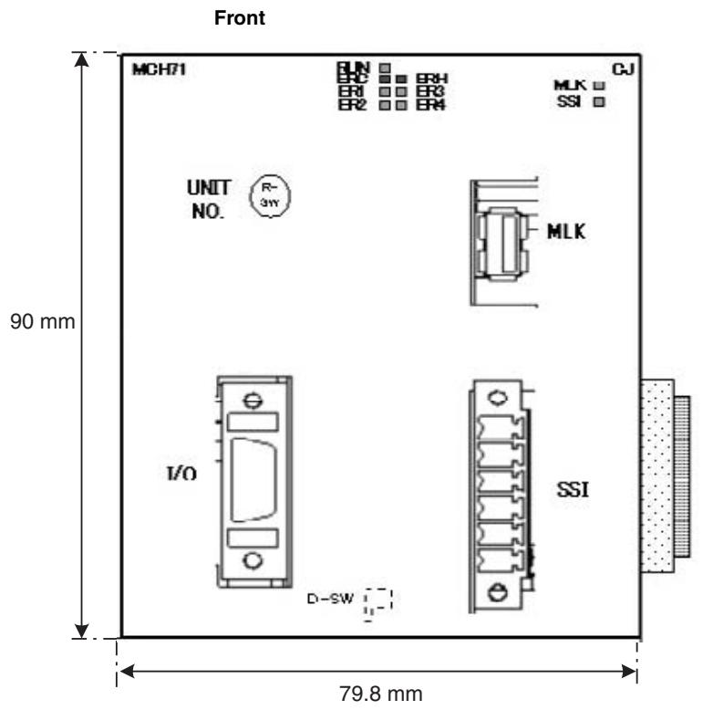
CJ1W-MCH71
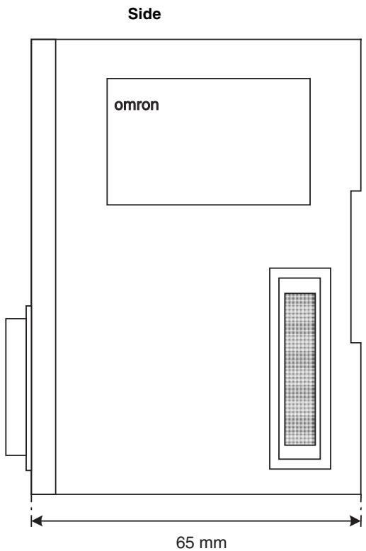
CS1W-MCH71
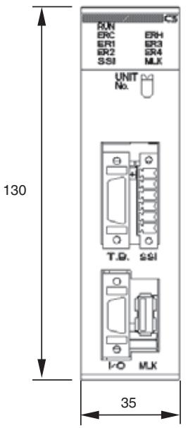
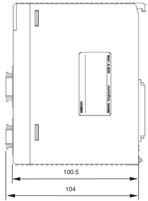
3-3 External I/O Circuitry
3-3-1 MECHATROLINK-II Connector
| Item | Description | |||
| Connector name | CN1 | MECHATROLINK-II connector | ||
| Applicable connector | USB connector | DUSB-ARA41-T11 (DDK) | ||
| Mating connector | USB connector | DUSB-APA41-B1-C50 (DDK) *Including shell. | ||
| Pin arrangement | ||||
| No. | Signal | I/O | Description | |
| 1 | (NC) | --- | --- | |
| 2 | SRD- | I/O | Send/Receive Data (-) | |
| 3 | SRD+ | I/O | Send/Receive Data (+) | |
| 4 | SLD | --- | Shield Ground | |
MECHATROLINK-II Standard Cable
USB connectors on both ends: JEPMC-W6003-**
3-3-2 I/O Connectors
| Item | Classification | Component and Maker |
| Connector name | CN2 | I/O connector |
| Applicable connec- tor | MDR connector | 10214-52A2JL (3M) |
| Mating connector | Connector | 10114-3000VE (3M) |
| Housing | 10314-52F0-008 (3M) |
| Item | Classification | Component and Maker | ||||||
| Pin arrangement | ||||||||
| No. | Signal | I/O | Description | No. | Signal | I/O | Description | |
| 1 | DI_24V | P | DI common | 8 | DI_24V | P | DI common | |
| 2 | DI_00 | I | DI input (Decel- eration stop) | 9 | DI_01 | I | DI input (Reserved) | |
| 3 | DI_02 | I | DI input 1 | 10 | DI_03 | I | DI input 2 | |
| 4 | --- | --- | --- | 11 | --- | --- | --- | |
| 5 | DO_24V | P | --- | 12 | DO_24V | P | --- | |
| 6 | DO_COM | P | DO common | 13 | DO_COM | P | DO common | |
| 7 | DO_00 | O.C. | DO00 output | 14 | DO_01 | O.C. | DO01 output | |
| P: Power supply input I: Input signal O.C.: Open collector output | ||||||||
CJ1W-MCH71 Pin Arrangement
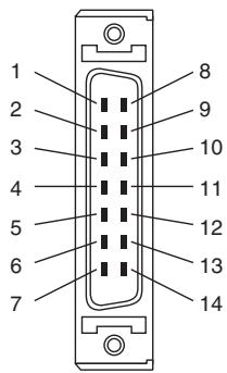
3-3-3 Wiring Connectors
Procedure:
1,2,3... 1.Pass each wire through heat-shrink tubing.
2. Spot-solder the wires and connector terminals
3. Solder the wires
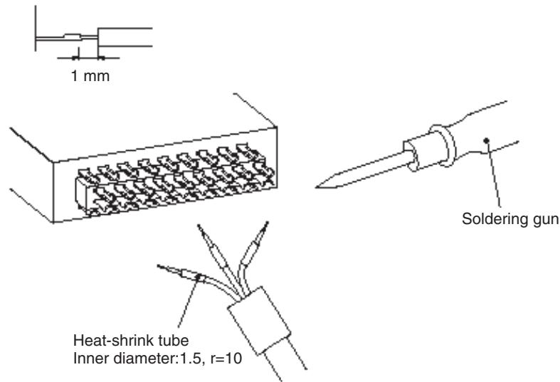
- Pull the heat-shrink tubing back over the soldered area and heat the tubing to shrink it.
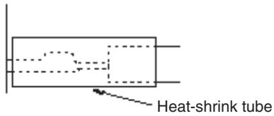
3-3-4 I/O Circuits (CJ1W-MCH71 and CS1W-MCH71 Units Version 3.0 and Later)
Connector Interface Circuits
24VDC Digital Output (2 outputs)
| Item | Specifications | Circuitry |
| Max. Output Current | 100 mA/24 VDC | +V DO_00 L DO_01 L DO_COM 24 VDC |
| Leakage current | 1 mA max. | |
| Residual Voltage | 1.5 V max. | |
| External Supply Voltage | 24 VDC ±10% | |
| Number of Common | 2 |
24 VDC Digital Input
| Item | Specifications | Circuitry | |
| Rated Input Voltage | 24 VDC ±10% | DI_00 | 2.7 kΩ 680 Ω |
| Rated Input Current | 4.02 to 4.52 mA (24 VDC) | ||
| ON Voltage | 14 V min. | DI_01 | 2.7 kΩ 680 Ω |
| OFF Current | 6 V max. | ||
| ON Response Time | 1 ms max. | ||
| OFF Response Time | 1 ms max. | ||
| Number of com-mons | 4 | DI_02 | 2.7 kΩ 680 Ω |
| 24 VDC | DI_03 | 2.7 kΩ 680 Ω | |
| 24V | DI_24V | 2.7 kΩ | |
3-3-5 I/O Circuits (CS1W-MCH71 Unit Version 2.0 and Earlier)
24 VDC Digital Output (2 outputs)
Connector Interface Circuits
| Item | Specifications | Circuitry |
| Max. Output Current | 100 mA/24 VDC | |
| Leakage current | 1 mA max. | |
| Residual Voltage | 1.5 V max. | |
| External Supply Voltage | 24 VDC ±10% | |
| Number of Common | 2 |
24 VDC Digital Input
| Item | Specifications | Circuitry | |
| Rated Input Voltage | 24 VDC ±10% | DI_00 | 2.7 kΩ 1 kΩ |
| Rated Input Current | 4.06 to 4.48 mA (24 VDC) | ||
| ON Voltage | 9.5 V min. | DI_01 | 2.7 kΩ 1 kΩ |
| OFF Current | 4.5 V max. | ||
| ON Response Time | 1 ms max. | ||
| OFF Response Time | 1 ms max. | ||
| Number of com-mons | 4 | DI_02 | 2.7 kΩ 1 kΩ |
| 2.01 μF | |||
| 2.7 kΩ | |||
| 2.7 kΩ | |||
| 2.7 kΩ | |||
| 2.7 kΩ | |||
| 2.7 kΩ | |||
| 2.7 kΩ | |||
| 2.7 kΩ | |||
| 2.7 kΩ | |||
| 2.7 kΩ | |||
| 2.7 kΩ 2.7 kΩ | |||
| 2.7 kΩ | |||
| 2.7 kΩ | |||
| 2.7 kΩ | |||
| 2.7 kΩ | |||
| 2.7 kΩ | |||
| 2.7 kΩ | |||
| 2.7 kΩ | |||
| 2.7 kΩ | |||
| DI_03 | |||
| DI_04V | |||
3-4 Wiring
3-4-1 Wiring Precautions
Heed the following precautions when wiring the MC Unit to the servo drivers and motors.
Electronically controlled equipment may malfunction because of noise generated by power supply lines or external loads. Such malfunctions are difficult to reproduce; hence, determining the cause often requires a great deal of time.
The following tips should aid in avoiding noise malfunction and improving system reliability.
Use electrical wires or cables of designated sizes as specified in the instruction manual for the servo driver.
Separate power cables (AC power supply lines and motor power supply lines) from control cables (pulse output lines and external input signal lines). Do not group the two types of cable together or place them in the same conduit.
Using the laminated ceramic capacitor of 1 F for the output of 24 VDC power supply will improve noise-resistance.
Use shielded cables for control lines.
For inductive loads such as relays or solenoid valves, connect surge absorbers.
The connecting cable for the servo driver must be the specified cable with ring core.
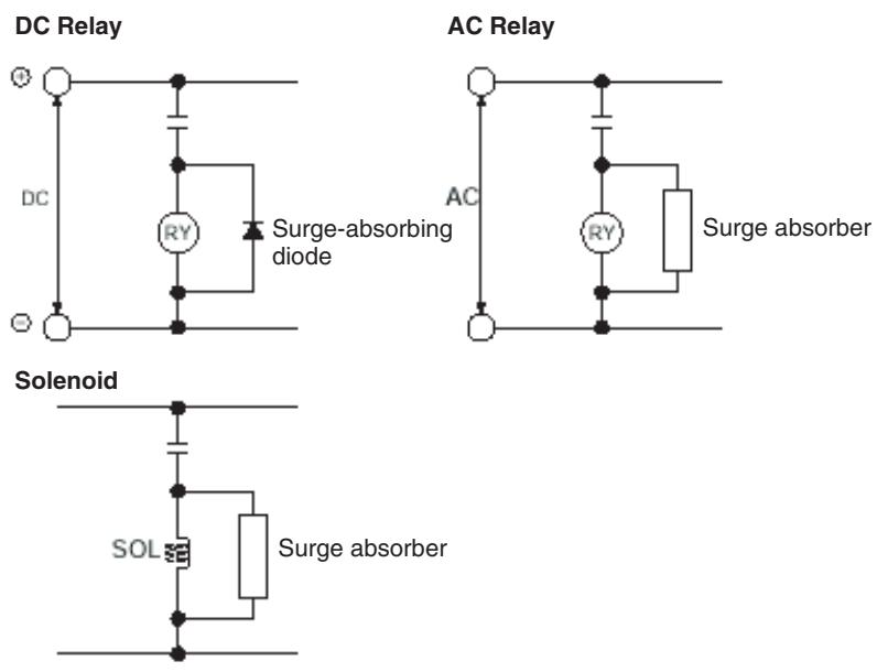
Note
(1) Connect a surge-absorbing diode or surge absorber close to the relay. Use a surge absorbing diode with a voltage tolerance at least five times greater than the circuit voltage.
(2) Noise may interfere from the power supply line if the same power supply as the electric welder or spark erosion machine is used for the MC Unit, or if there is a source of high-frequency noise around. If it occurs, insert the noise filter at the input section of the power supply.
(3) Use the twisted pair-cable for the power line.
(4) Provide grounding of 100 or less and use the thickest possible wire, greater than 1.25 square mm.
3-5 Connecting MECHATROLINK Devices
This section explains the method of connecting the MC Unit to devices with MECHATROLINK-II.
(As for the method of setting parameters, refer to 10-2 Slave Modules (page 607).)
Note
For details, refer to YASKAWA ELECTRIC CORPORATION's -II SERIES SGDH MECHATROLINK-II APPLICATION MODULE USER'S MANUAL MODEL: JUSP-NS115 (MANUAL NO. SIEPC71080001*)".
3-5-1 Method of Connecting MECHATROLINK Devices
Connection cable
To connect MECHATROLINK devices to MC units, use the connecting cables (sold separately) in the table below.
| Name | Model (OMRON) | Model (YASKAWA) | Length |
| MECHATROLINK-II cable (For W-series or SMART-STEP Junior Servo Drive) (With ring core and USB connector on both ends) | FNY-W6003-A5 | JEPMC-W6003-A5 | 0.5 m |
| FNY-W6003-01 | JEPMC-W6003-01 | 1.0 m | |
| FNY-W6003-03 | JEPMC-W6003-03 | 3.0 m | |
| FNY-W6003-05 | JEPMC-W6003-05 | 5.0 m | |
| FNY-W6003-10 | JEPMC-W6003-10 | 10.0 m | |
| FNY-W6003-20 | JEPMC-W6003-20 | 20.0 m | |
| FNY-W6003-30 | JEPMC-W6003-30 | 30.0 m |
The terminating resistance (sold separately) in the table below should be connected to the MECHATROLINK-II termination.
| Name | Model (OMRON) | Model (YASKAWA) |
| Terminating resistance for MECHA-TROLINK-II | FNY-W6022 | JEPMC-W6022 |
Repeater unit
When MECHATROLINK-II devices are connected up to 16 nodes (within 30m ) or 15 nodes (within 50m ), no repeater unit is required. A repeater unit is required to connect MECHATROLINK-II devices more than the cases above.
| Name | Model (OMRON) | Model (YASKAWA) |
| Repeater for MECHATROLINK-II | FNY-REP2000 | JEPMC-REP2000 |
3-5-2 Servo Driver (W-series WT□□□)
W-series Servo Driver requires YASKAWA MECHATROLINK-II Interface Unit model JUSP-NS115.
Each version of the following products can be used. The version name is indicated on the nameplates of each product.
W-series Servo Driver: Ver.39 or later
I/F Unit: VER.***03 or later
Note Using either a W-series Servo Driver or an I/F Unit of older versions can be the cause of abnormal operations. Make sure to use the versions mentioned above.
Attaching I/F Unit NS115
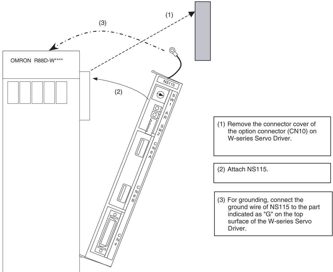
Communications setting
Set MECHATROLINK communications using SW1 and SW2.
Transmission setting
MECHATROLINK communications can be specified using the DIP switches (SW2). See the table below.
Any change of the settings becomes valid after turning OFF the power once, then ON again.
| SW2 | Name | Setting | Content | Default setting |
| Bit 1 | Baud rate | OFF | 4 Mbps | ON (Do not change.) |
| ON | 10 Mbps | |||
| Bit 2 | No. of Transmitted bytes | OFF | 17 bytes | ON (Do not change.) |
| ON | 30 bytes | |||
| Bit 3 | Station address | OFF | Refer to Station address setting | OFF |
| ON | ||||
| Bit 4 | Reserved | OFF | --- | OFF |
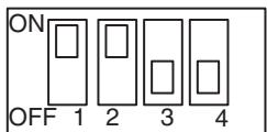
SW2(Default setting)
Station address setting
The station address can be set as shown in the table below using the rotary switch (SW1) and piano switch (SW2 bit 3).
The piano switch 3 of SW2 specifies the number of 10s and SW1 specifies the number of units.
Do not change the setting while the power is being supplied.
| Bit 3 of SW2 | SW1 | Station No. | SW1 default setting |
| OFF | 0 | Do not set. | 1 |
| 1 to F | 1 to 15 (1 to FH) | ||
| ON | 0 to F | 16 to 30 (10H to 1EH) |
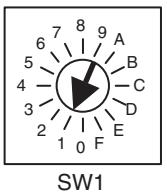
Example of connecting I/O signals
A typical connecting example with standard settings (default settings) is shown here.
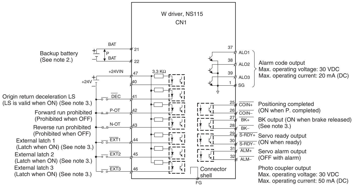
Connect shield to connector shell.
Note (1) P indicates twisted-pair wires.
(2) When using an ABS encoder, connect a backup battery only when there is no battery connected to CN8.
(3) Allocate signals using parameters.
CN1 terminal layout
CN1 terminal layout
| 2 | SG | GND | 1 | SG | GND | 27 | /BK+ (See note 3.) | Brake interlock output | 26 | /COIN- | Positioning complete output |
| 3 | 29 | /S-RDY+ | Servo ready output | 28 | /BK-(See note 3.) | Brake interlock output | |||||
| 4 | 5 | 30 | /S-RDY- | Servo ready output | |||||||
| 6 | SG | GND | 7 | 31 | ALM+ | Servo alarm output | 32 | ALM- | Servo alarm output | ||
| 8 | 9 | 33 | 34 | ||||||||
| 10 | SG | GND | 11 | 35 | 36 | ||||||
| 12 | 13 | 37 | ALO1 | Alarm code output (Open-collector output) | 38 | ALMO2 | Alarm code output | ||||
| 14 | 15 | 39 | ALO3 | 40 | |||||||
| 16 | 17 | 41 | /DEC (See note 3.) | Origin return deceleration LS input | 42 | P-OT | Forward run prohibited input | ||||
| 18 | 19 | 43 | N-OT | Reverse run prohibited input | 44 | /EXT1 (See note 3.) | External latch signal 1 input | ||||
| 20 | 21 | BAT(+) | Battery (+) | 45 | /EXT2 (See note 3.) | External latch signal 2 input | 46 | /EXT3 (See note 3.) | External latch signal 3 input | ||
| 22 | BAT(-) | Battery (-) | 23 | 47 | +24VIN | External power supply input | 48 | ||||
| 24 | 25 | /COIN | Positioning completed output | 49 | 50 |
Note
(1) Connector shell: Connected to FG (Frame ground)
(2) Do not use unused terminals for relays.
(3) Allocate signals using parameters.
(4) For details, refer to YASKAWA ELECTRIC CORPORATION's Σ-II SERIES SGDH MECHATROLINK-II APPLICATION MODULE USER'S MANUAL MODEL: JUSP-NS115 (MANUAL NO. SIEPC71080001*)".
3-5-3 24 VDC I/O Module
Communications setting
Set MECHATROLINK communications using SW1 and SW2.
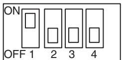
SW1(Default setting)
Transmission settings
MECHATROLINK communications can be specified using the DIP switch (SW1). See the table below.
Any change of the settings becomes valid after turning OFF the power once, and then ON again.
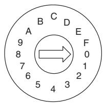
SW2(Default setting)
| SW1 | Name | Setting | Content | Default setting |
| 1 | Baud rate | OFF | 4 Mbps | ON (Do not set to OFF.) |
| ON | 10 Mbps | |||
| 2 | No. of Transmitted bytes | OFF | 17 bytes | OFF |
| ON | 30 bytes | |||
| 3 | Station address | OFF | Refer to Station address setting | OFF |
| ON | ||||
| --- | Reserved | OFF | --- | OFF |
Station address setting
Station address can be set as shown in the table below using the rotary switch (SW2) and piano switch (SW1 bit 3).
The bit 3 of SW1 specifies the number of 10s while the SW2 specifies the number of units.
Do not change the setting while the power is being supplied.
| Bit 3 of SW1 | SW2 | Station address | SW2 default setting |
| OFF | 0 | Do not set. | 0 |
| 1 to F | 1 to 15 (1 to FH) | ||
| ON | 0 to F | 16 to 30 (10H to 1EH) |
64-point I/O module (IO2310) connector pin layout, signal names, and wiring example
For details, refer to YASKAWA ELECTRIC CORPORATION's "Machine Controller MP900 Series MECHATROLINK System USER'S MANUAL (MANUAL NO. SIEZ-C887-5.1*)".
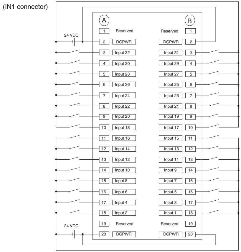
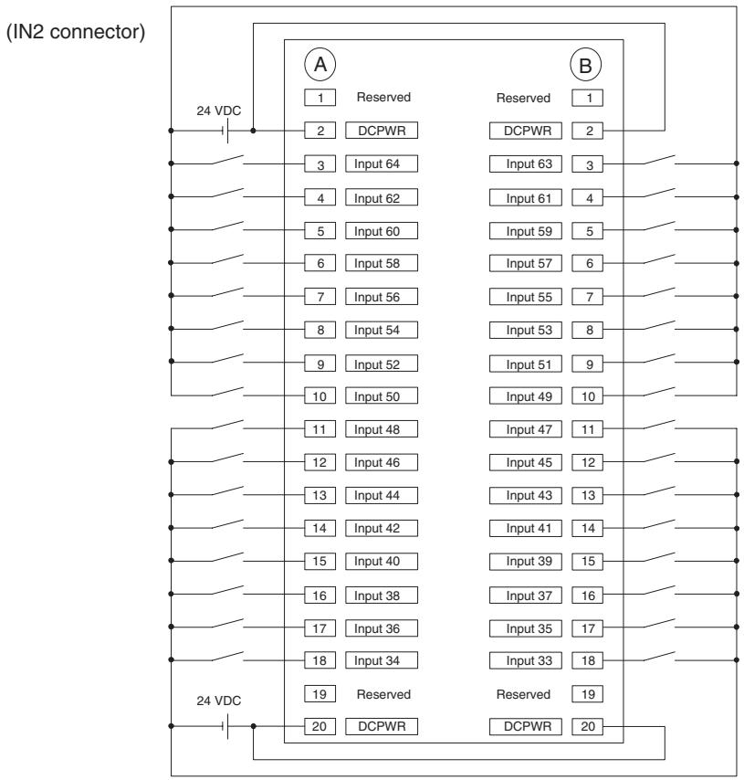
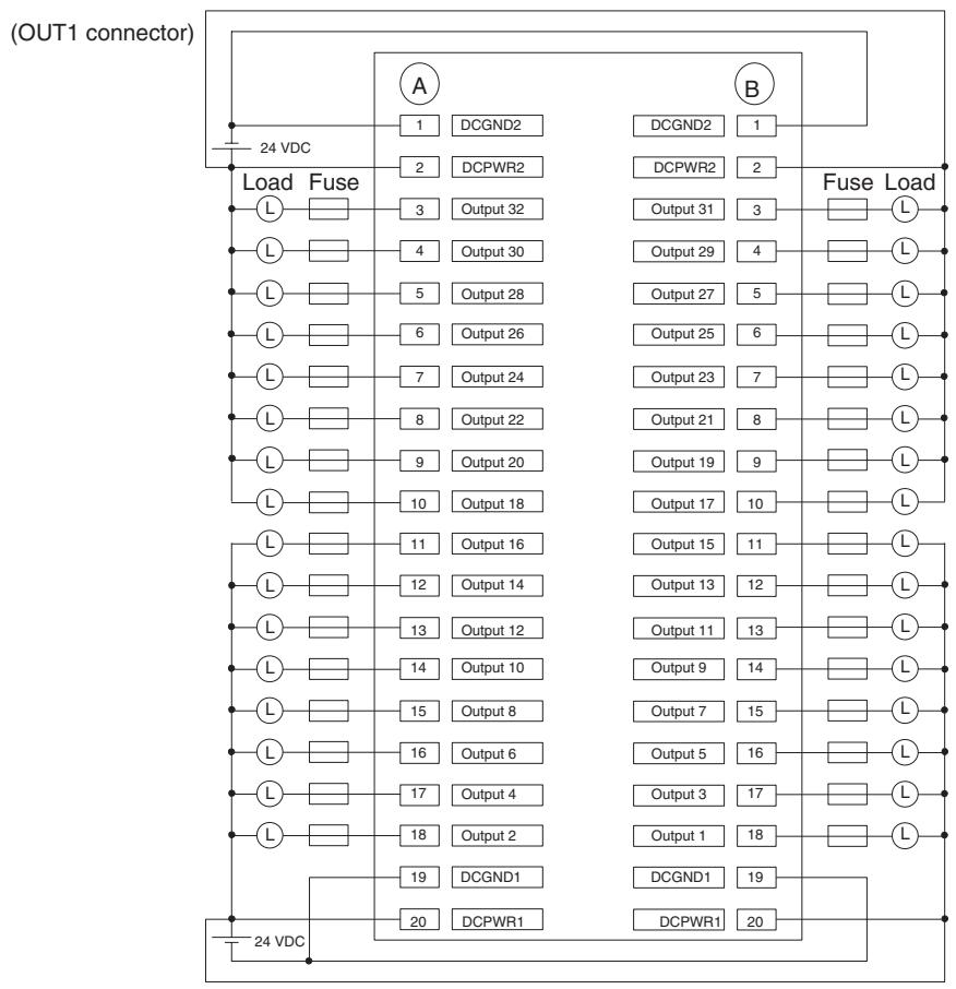
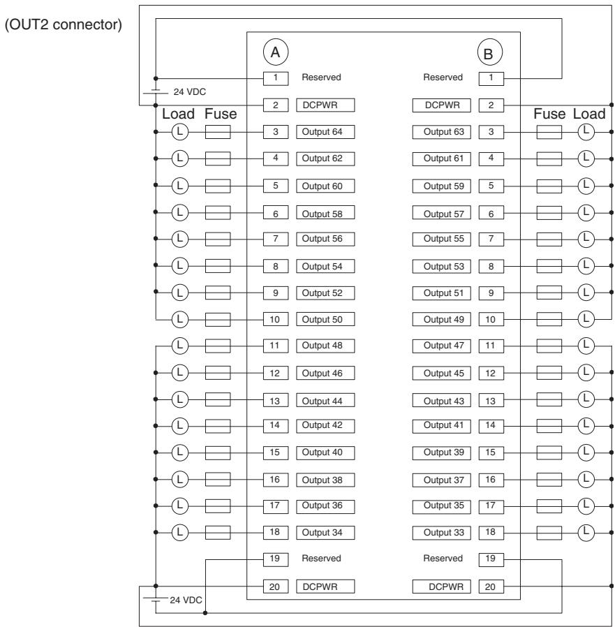
3-5-4 Counter Module, Pulse Output Module
Communications setting
For counter modules and pulse output modules, MECHATROLINK communications can be set using the DIP switches.
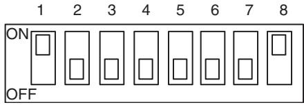
SW(Default setting)
Transmission setting
MECHATROLINK communications can be specified using the DIP switches (SW) 6 to 8.
See the table below.
Any change of the settings becomes valid after turning OFF the power once, then ON again.
| Pin | Name | Setting | Content | Default setting |
| 6 | Baud rate | OFF | 4 Mbps | OFF |
| ON | 10 Mbps | |||
| 7 | Transmission bytes | OFF | 17 byte | OFF |
| ON | 30 byte | |||
| 8 | Station address | OFF | Refer to Station address setting | ON (Do not set to OFF.) |
| ON |
Station address setting
Station address can be set as shown in the table below using the DIP switch 1 to 5 (SW).
The bit 5 of SW specifies the number of 10s while the bit 1 to 4 of SW specifies the number of units.
Do not change the setting while the power is being supplied.
| SW | Station address | ||||
| 5 | 4 | 3 | 2 | 1 | |
| OFF | OFF | OFF | OFF | OFF | Do not set. |
| OFF | OFF | OFF | OFF | ON | 1 (01H): Default setting |
| OFF | OFF | OFF | ON | OFF | 2 (02H) |
| OFF | OFF | OFF | ON | ON | 3 (03H) |
| to | to | ||||
| OFF | ON | ON | ON | ON | 15 (0FH) |
| ON | OFF | OFF | OFF | OFF | 16 (10H) |
| ON | OFF | OFF | OFF | ON | 17 (11H) |
| ON | OFF | OFF | ON | OFF | 18 (12H) |
| ON | OFF | OFF | ON | ON | 19 (13H) |
| to | to | ||||
| ON | ON | ON | ON | ON | Do not set. |
Counter module (PL2900) Circuit Configuration and signal connection
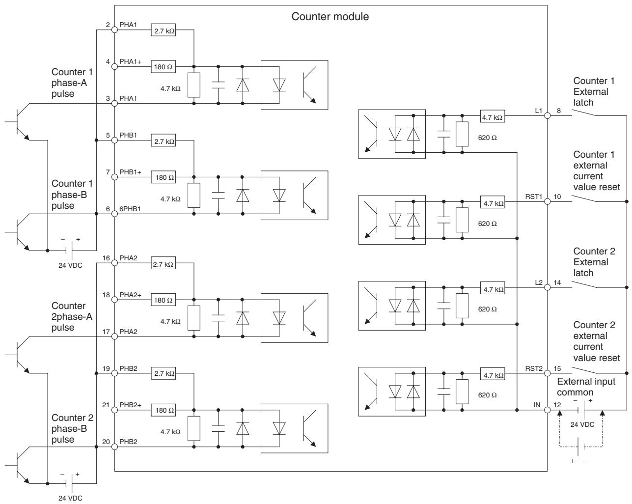
Signal arrangement of the terminal block
| 1 | 3PHA1- | 5PHB1 | 7PHB1+ | 9N1 | 11OUT- | 13N2 | 15RST2 | 17PHA2- | 19PHB2 | 21PHB2+ | 23+24V | |||||||||||
| 2PHA1 | 4PHA1+ | 6PHB1- | 8L1 | 10RST1 | 12IN- | 14L2 | 16PHA2 | 18PHA2+ | 20PHB2- | 220(24V) | ||||||||||||
For details, refer to YASKAWA ELECTRIC CORPORATION's "Machine Controller MP900 Series MECHATROLINK System USER'S MANUAL (MANUAL NO. SIEZ-C887-5.1*)".
Pulse output module (PL2910)
Circuit configuration and signal arrangement
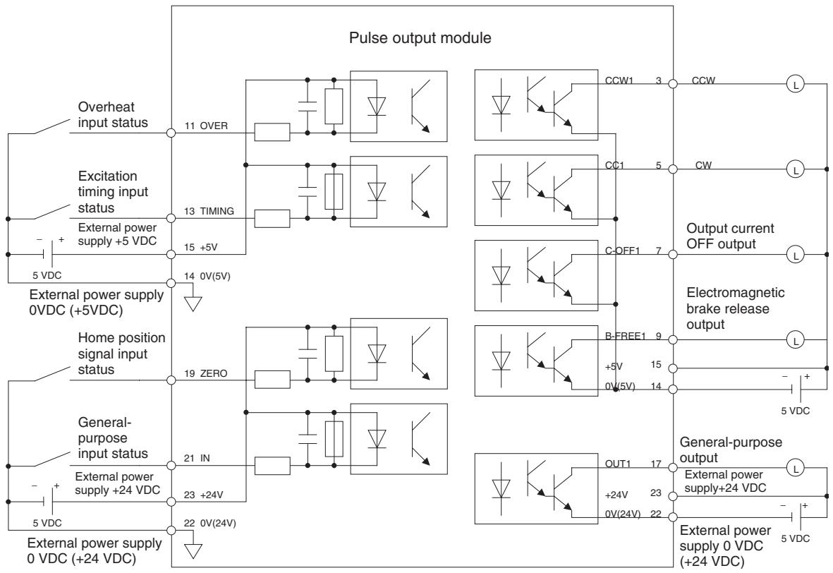
Signal arrangement of the terminal block
| 1 FG | 3 CCW1 | 5 CW1 | 7 COFF1 | 9 BFRE1 | 11 OVER1 | 13 TIMG1 | 15 +5V | 17 OUT1 | 19 ZERO1 | 21 IN1 | 23 +24V |
| 2 CCW2 | 4 CW2 | 6 COFF2 | 8 BFRE2 | 10 OVER2 | 12 TIMG2 | 14 0(5V) | 16 OUT2 | 18 ZERO2 | 20 IN2 | 22 0(24V) |
For details, refer to YASKAWA ELECTRIC CORPORATION's "Machine Controller MP900 Series MECHATROLINK System USER'S MANUAL (MANUAL NO. SIEZ-C887-5.1*)".
This section describes the data configuration uses to set up, operate, and monitor the CJ1W-MCH71 and CS1W-MCH71 Motion Control Units and related devices.
4-1 Data Configuration 56
4-1-1 DATA 56
4-1-2 Data Configuration 58
4-2 System Parameters 58
4-2-1 Description of System Parameters 58
4-2-2 System Parameters 59
4-2-3 Data Configuration and Content of System Parameters 66
4-2-4 Concept of Parameters 103
4-2-5 Timing that Enables Transferred System Parameters. 105
4-3 Variables 105
4-3-1 Overview of Variables 105
4-4 Position Data. 107
4-4-1 Position Data Address. 108
4-4-2 Position Data Configuration 108
4-4-3 Indirect Specification 108
4-4-4 Methods Used to Read, Write and Transfer Position Data. 110
4-5 System Variables. 111
4-5-1 System Variables. 111
4-6 I/O Variables 160
4-6-1 I/O Variables Overview 160
4-6-2 List of Input Variables 160
4-6-3 List of Output Variables 175
4-7 Present Position Preset 190
4-8 Servo Parameter 191
4-8-1 Servo Parameter Overview 191
4-8-2 Data Configuration and Contents of Servo Parameters 192
4-8-3 Motor Parameters 203
4-8-4 Setting Method Using Combination of W Series and NS115 206
4-9 CAM Data. 210
4-1 Data Configuration
Data Type
There are five different types of date for MC Unit.
1,2,3...
- System parameters
Unit parameters
Motion task parameters
Axis parameters (allocation, speed, position, origin, and machine)
- Variables
System variables
Global general variables
Input variables
Output variables
Position data
Task variables
- Present position preset
- Servo parameter axis specification
- Servo parameter
Note Neither CAM data nor programs are treated as data. For more details, see 4-9 CAM Data (Page 210) and SECTION 6 Programming.
4-1-1 DATA
| Classification | IORD/IOWR Control Address | Variables | WORD | Contents | |
| Variables | |||||
| Position data | 0000h-27FFh | PLhhhh | 10240 | Data indicating positions, Total number is 10240. | |
| System variables | 3000h-33FFh | S*hhh | 1024 | Statuses such as the operating mode, error log, etc. of MC Unit | |
| Global general Variables | Nil | M*hhh | 8192 | Variables that can be accessed from all tasks.Use for data communications between tasks and operations. | |
| Input variables | Nil | I*hhh | 2048 | Input status from CPU Unit or MECHATROLINK-II devices | |
| Output variables | Nil | O*hhh | 2048 | Executes outputs from programs to CPU Unit or MECHATROLINK-II devices | |
| Task variables | Nil | D*hhh | 128 × 9 tasks | Variables that can be used only in each task. Use as works in operation. | |
| Present position preset | 4000h-401Fh | Nil | 32 | Sets each axis's preset value for present position. | |
| Classification | IORD/IOWR Control Address | Variables | WORD | Contents | |
| System parameter | |||||
| Unit | 5000h-501Fh | Nil | 4096 | ·System parameters are consisted of unit parameters, task parameters and axis parameters. ·The system information used by the MC Unit, such as number of axes and tasks, feed rate, operat-ing range etc. | |
| Motion task | 5020h-511Fh | ||||
| Reserved | 5120h-513Fh | ||||
| Data tracing | 5140h-51BFh | ||||
| Reserved | 51C0h-533Fh | ||||
| Axis: Allocations | 5340h-55BFh | ||||
| Axis: Speed | 55C0h-583Fh | ||||
| Axis: Position | 5840h-5ABFh | ||||
| Axis: Origin | 5AC0h-5D3Fh | ||||
| Axis: Machine | 5D40h-5FBFh | ||||
| Zones | 5FC0h-5FFFh | ||||
| Servo parameter axis Specification | 6000h | 6000h | 1 | Specifies the axis to access. | |
| Servo parameter | 7000h-78FFh | Nil | 4096 | Parameters of servo driver. | |
Data Access Method
- The letters to identify data access type, hhhh: 4 digits hexadecimal address
The following methods are used to access to each data. For further details, refer to SECTION 5 Data Transfer and Storage (Page 212).
1,2,3...
- Use the Support Tool (CX-Motion-MCH).
- Execute IOWR/ORD instructions (Intelligent I/O Write/Read) from the ladder program.
- Variables can be used in the MC Unit's programs.
"IORD/IOWR Control Address" is the internal address to identify data when IORD/IOWR instructions are executed from the ladder program. Global variables, input variables, output variables, or task variables cannot be accessed. See 4-3 Variables (Page 105) for details.
Basic Data Usage
System parameters:Created with the Support Tool (CX-Motion-MCH), and transferred to the MC Unit. Using the IOWR instruction during CPU Unit's operation can change the system parameters as needed.
Position data: Created with the Support Tool (CX-Motion-MCH), and transferred to the MC Unit. Using the IOWR instruction during CPU Unit's operation can change the position data as needed. It is possible to change the position data also by using MC Unit's program.
System variables: Read with the IORD instruction from the ladder program while the CPU Unit is running. It is also possible to read it from MC Unit's programs.
Servo parameters: Created with the Support Tool (CX-Motion-MCH), and transferred to the MC Unit. Using the IOWR instruction during the CPU Unit's operation can change the system parameters as needed. To use the IOWR instruction, the axis whose parameters are to be changed has to be specified in advance.
Other variables: Global general variables, input variables, output variables, and task variables can be used in MC Unit's programs.
4-1-2 Data Configuration

4-2 System Parameters
The system parameters are consisted of the following three different parameters.
- Unit parameters
Motion task parameters - Axis parameters (Allocations, Speed, Position, origin, Machine)
4-2-1 Description of System Parameters
The following table describes the functions of each parameter group.
| Parameters | Number | IORD/IOWR Addresses (See note 3.) | Functions | |
| Unit | P00001-P00010 | 5000h-5009h | Used to specify information inherent to the Unit, such as the number of axes used and the number of tasks. | |
| Motion task | P00M01-P00M21 (See note 1.) | 5020h-5114h | Used to specify usage of each motion task such as max. interpolation feed rate. | |
| Data tracing | P05T01-P05T45 (See note 4.) | --- | Sets the trace conditions and the data to be traced. | |
| Parameters | Number | IORD/IOWR Addresses (See note 3.) | Functions | |
| Axes | Allocations | P1AA01-P1AA09 (See note 2.) | 5340h-55B4h | Specifies axis type and device to be used for each axis. |
| Speed | P2AA01-P2AA12 (See note 2.) | 55C0h-5837h | Specifies max. rapid feed rate and type of acceleration and deceleration etc. for each axis. | |
| Position | P3AA01-P3AA09 (See note 2.) | 5840h-5AB4h | Specifies the methods regarding to position such as software limit, error counter warning etc. for each axis. | |
| Origin | P4AA01-P4AA12 (See note 2.) | 5AC0h-5D37h | Specifies the method of origin search for each axis. | |
| Machine | P5AA01-P1AA09 (See note 2.) | 5D40h-5FB4h | Specifies the machine information such as unit systems, gear ratio, etc. to be used for each axis. | |
| Zones | P6ZZ01-P6ZZ02 (See note 5.) | 5FC0h-5FFFh | Sets the variables to be monitored using the zone function, and sets the bits for outputting the monitoring results. | |
Note
(1) The task number 1 to 8 is to be inserted in M.
(2) The axis number 1 to 32 is to be inserted in AA.
(3) The IORD/IOWR addresses in this table are the actual address range (excluding reserved ones).
(4) The group number (1 or 2 is inserted in place of T)
The trace parameters can be written only by using the Support Tool.
(5) The zone bit number (1 to 32 is inserted in place of ZZ)
(6) The parameter number is notated in 5-digit decimal in this manual.
| P | |||||
| Detail numberFor the Unit: 1 to 32For motion tasks: 1 to 32For tracing: 1 to 45For zones: 1 or 2 | Axis allocations: 1 to 20Axis-speed: 1 to 20Axis-position: 1 to 20Axis-origin: 1 to 20Axis-machine: 1 to 20 | ||||
| Group number | |||||
| UnitMotion taskTracingAxis: AllocationsSpeedPositionOriginMachineZone | 000001-008050 + Group number100 + Axis No.200 + Axis No.300 + Axis No.400 + Axis No.500 + Axis No.600 + Zone bit number | “00M” (M=1 to 8)“05T” (T=1 to 2)“1AA” (AA=1 to 32)“2AA” (AA=1 to 32)“3AA” (AA=1 to 32)“4AA” (AA=1 to 32)“5AA” (AA=1 to 32)“6ZZ” (ZZ=1 to 32) | |||
4-2-2 System Parameters
Unit Parameters
| Number | Address | Name | Function | Page |
| P00001 | 5000h | No. of motion tasks | Sets how many motion tasks are to be used. | 67 |
| P00002 | 5001h | No. of parallel branches | Sets the numbers of parallel branches and simultaneous execution commands common in each motion task. | 67 |
| P00003 | 5002h | Unit scan time | Specifies the unit scan time. | 68 |
| P00004 | 5003h | Unit function select | ·Specifies method of specifying the speed in helical circular interpolation under MOVEC command. ·Specifies center-positioning method for MOVEC command ·Specifies the speed command unit for SPEED command/feedback speed. ·Selects output method for positioning completed/positioning completed 2 signals. ·Specifies the method for changing the direction for JOG operation. ·Specifies support for 3-ms communications cycle. ·Specifies the type of continuous operation for multi-turn operation for an infinite axis ·Specifies behavior when an overtravel alarm occurs ·Specifies the number of parallel branches for each Unit and each task. ·Specifies origin establishment and status hold for present position preset. ·Specifies the operation (deceleration stop or servo OFF) for deceleration stop signal inputs. | 68 |
| P00005 | 5004h | Reserved | ||
| P00006 | 5005h | General I/O Dis-abled/Enabled | Specifies general I/O signals disable/enable for MC unit. | 70 |
| P00007 | 5006h | Input control 1 from PLC | Specifies whether input signals from CPU to the Unit or motion tasks are enabled or disabled. | 71 |
| P00008 | 5007h | Input control 2 from PLC | Specifies whether input signals from CPU to axes are enabled or disabled. | 72 |
| P00009 | 5008h | Setting for the No. of MECHATROLINK-II Retrial Nodes, With/ without C2 master | ·No. of retrial nodes: Specifies the number of nodes to be retried within MECHATROLINK-II communication cycle. ·With/without C2 master: Set this parameter when there is a master unit other than MC unit. (reserved) | 74 |
| P00010 | 5009h | MECHATROLINK-II Delay in Communi-cation Start | Specifies the time to make the communication start delayed in order to wait for slave startup. | 74 |
| P00011 | 500Ah | Number of zone bits | Specifies the number of zone bits to be used. | page 75 |
| P00012 | 500Bh | Zone data leading address | Specifies the leading address for the zone data (upper and lower limits) used by the zone bits. | page 75 |
| P00013 -P00032 | 500Ch -501Fh | Reserved | --- |
Motion Task Parameters
Note Abbreviation in the No. column: M = 1 to 8 (motion task number) Abbreviation in the address column: M = 0 to 7 (motion task number - 1)
| No. M = 1-8 | Address M = 0-7 | Name | Function | Page |
| P00M01 | 5020h + (M * 20h) | Max. interpolation feed rate | Sets the maximum feed rate (F command) in interpolation operation | 76 |
| P00M02 | 5021h + (M * 20h) | Interpolation feed acceleration time | Sets the time required to accelerate from zero to max. interpolation feed rate. | 76 |
| P00M03 | 5022h + (M * 20h) | Interpolation feed deceleration time | Sets the time required to decelerate from max. interpolation feed rate to zero in interpolation. | 77 |
| P00M04 | 5023h + (M * 20h) | Interpolation S-curve filter enabled | Selects enable /disable of S-curve filter at the interpolation feed rate. | 77 |
| P00M05 | 5024h + (M * 20h) | Interpolation S-curve time constant | Sets the S-curve filter time constant at the interpolation feed rate. | 78 |
| P00M06 | 5025h + (M * 20h) | Pass mode select | Sets the combination of the interpolation Accel/decel time and Pass mode with fixed acceleration disabled/enabled. | 78 |
| P00M07 | 5026h + (M * 20h) | Initial modal data 1 MOVE command value select | Specifies the initial value if ABL/INC specification has been omitted in a motion program. | 79 |
| P00M08 | 5027h + (M * 20h) | Initial modal data 2 operating mode select | Specifies the initial value if PASSMODE/STOPMODE specification has been omitted in a motion program. | 79 |
| P00M09 | 5028h + (M * 20h) | Initial model data 3 interpolation feed rate | Specifies the initial value if interpolation feed rate (F com-mand) has been omitted in a motion program. | 79 |
| P00M10 | 5029h + (M * 20h) | Interpolation feed decimal point position | Sets the method of interpreting the speed command value specified by an immediate value with a decimal point. | 80 |
| P00M11 - P00M20 | 502Ah + (M * 20h) - 5033h + (M * 20h) | Interpolation feed acceleration/deceler-ation bank 1 - Interpolation feed acceleration/deceler-ation bank 10 | Specifies the acceleration/deceleration times to use dur-ing interpolation. Banks are used to enable quickly switching acceleration/deceleration times with the PARAM command. | 80 |
| Interpolation feed acceleration banks 1 to 5 - Interpolation feed deceleration banks 1 to 5 | ||||
| P00M21 | 5034h + (M * 20h) | Number of parallel branches in each task | Specifies the number of parallel branches used in a motion task and the number of commands simultaneously executed. | page 82 |
| P00M22 - P00M32 | 5035h + (M * 20h) - 503Fh + (M * 20h) | Reserved | --- |
Trace Parameters (Supported for unit version 3.0 and later
Note Abbreviation in the No. column: T = 1 or 2 (trace group number)
| No.M = 1-8 | AddressM = 0-7 | Name | Function | Page |
| P05T01 | --- | Number of trace points and trace data | These parameters are used to set trigger conditions, numbers of data items to be traced, addresses of variables to be traced, and trace timing. These parameters can be set only by using the Sup-port Tool. They cannot be set by IOWR instructions in ladder programs or by PARAM commands in motion programs.When these parameters are saved from the ladder program, they are saved in the MC Unit's FROM just as with other parameters.The CPU easy backup operation can also be used to save these parameters to CF (Compact Flash), and to the MC Unit's F-ROM from the CF.For details on these parameters, refer to the CX-Motion-MCH Operation Manual (supported by version 2.0 or later). | --- |
| P05T02 | --- | Trace start at power ON | ||
| P05T03 | --- | Delay | ||
| P05T04 | --- | Trace start trigger 1: Left-side variable type/form | ||
| P05T05 | --- | Trace start trigger 1: Left-side address | ||
| P05T06 | --- | Trace start trigger 1: Criteria | ||
| P05T07 | --- | Trace start trigger 1: Right-side variable type | ||
| P05T08 | --- | Trace start trigger 1: Right-side address or immediate value | ||
| P05T09 | --- | Trace start trigger 2: Left-side variable type/form | ||
| P05T10 | --- | Trace start trigger 2: Left-side address | ||
| P05T11 | --- | Trace start trigger 2: Criteria | ||
| P05T12 | --- | Trace start trigger 2: Right-side variable type | ||
| P05T13 | --- | Trace start trigger 2: Right-side address or immediate value | ||
| P05T14 | --- | Trace item 1: Form/type | ||
| P05T15 | --- | Trace item 1: Address | ||
| P05T16 | --- | Trace item 2: Form/type | ||
| P05T17 | --- | Trace item 2: Address | ||
| P05T18 | --- | Trace item 3: Form/type | ||
| P05T19 | --- | Trace item 3 Address | ||
| P05T20 | --- | Trace item 4: Form/type | ||
| P05T21 | --- | Trace item 4: Address | ||
| P05T22 | --- | Trace item 5: Form/type | ||
| P05T23 | --- | Trace item 5: Address | ||
| P05T24 | --- | Trace item 6: Form/type | ||
| P05T25 | --- | Trace item 6: Address | ||
| P05T26 | --- | Trace item 7: Form/type | ||
| P05T27 | --- | Trace item 7: Address | ||
| P05T28 | --- | Trace item 8: Form/type | ||
| P05T29 | --- | Trace item 8: Address | ||
| P05T30 | --- | Trace item 9: Form/type | ||
| P05T31 | --- | Trace item 9: Address | ||
| P05T32 | --- | Trace item 10: Form/type | ||
| P05T33 | --- | Trace item 10: Address | ||
| P05T34 | --- | Trace item 11: Form/type | ||
| P05T35 | --- | Trace item 11: Address | --- | |
| P05T36 | --- | Trace item 12: Form/type | ||
| P05T37 | --- | Trace item 12 Address | ||
| P05T38 | --- | Trace item 13: Form/type | ||
| P05T39 | --- | Trace item 13 Address | ||
| P05T40 | --- | Trace item 14: Form/type | ||
| P05T41 | --- | Trace item 14 Address | ||
| P05T42 | --- | Trace item 15: Form/type | ||
| P05T43 | --- | Trace item 15 Address | ||
| P05T44 | --- | Trace item 16: Form/type | ||
| P05T45 | --- | Trace item 16 Address |
Axis-Allocation Parameters
Note Abbreviation in the No. column: AA = 1 to 32 (axis number)
Abbreviation in the address column: AA = 0 to 31 (axis number - 1)
| No. AA = 1-32 | Address AA = 0-31 | Name | Function | Page |
| P1AA01 | 5340h + (AA * 14h) | Physical axis setting | Specifies the usage of physical axis. | 82 |
| P1AA02 | 5341h + (AA * 14h) | MECHATROLINK-II device classification | Sets classification of devices connected as MECHA-TROLINK-II slave nodes. | 83 |
| P1AA03 | 5342h + (AA * 14h) | Input allocation points | Specifies the No. of points for input signals of MECHA-TROLINK-II slave nodes allocated to input variables of MC Unit. | 83 |
| P1AA04 | 5343h + (AA * 14h) | Output allocation points | Specifies the No. of points for output signals of MECHA-TROLINK-II slave nodes allocated to output variables of MC Unit. | 84 |
| P1AA05 | 5344h + (AA * 14h) | Axis allocation first address | This is the setting for the counter input/pulse output count values of MECHATROLINK-II output to the present position of MC Unit. | 84 |
| P1AA06 | 5345h + (AA * 14h) | MECHATROLINK-II communications error detection | Sets the No. of allowable times of communications errors on MECHATROLINK-II device. | 84 |
| P1AA07 | 5346h + (AA * 14h) | Reserved | --- | |
| P1AA08 | 5347h + (AA * 14h) | Reserved | --- | |
| P1AA09 | 5348h + (AA * 14h) | Reserved | --- | |
| P1AA10 | 5349h + (AA * 14h) | Reserved | --- | |
| - P1AA20 | 5353h + (AA * 14h) |
Axis-Speed Parameters
Note Abbreviation in the No. column: AA = 1 to 32 (axis number)
Abbreviation in the address column: AA = 0 to 31 (axis number - 1)
| No.AA = 1-32 | AddressAA = 0-31 | Name | Function | Page |
| P2AA01 | 55C0h + (AA * 14h) | Max. rapid feed rate | Sets the maximum speed on machine's side for MOVE Command, etc. | 85 |
| P2AA02 | 55C1h + (AA * 14h) | Max. manual feed rate | Sets maximum speed on machine's side in JOG, STEP, DATUM operations. | 86 |
| P2AA03 | 55C2h + (AA * 14h) | Rapid feed rate | Sets the speed on machine's side for MOVE command, etc. | 86 |
| P2AA04 | 55C3h + (AA * 14h) | Manual feed rate | Sets the speed on machine's side in JOG, STEP operations. | 86 |
| P2AA05 | 55C4h + (AA * 14h) | Rapid feed acceleration time | Sets the time required to accelerate from zero to max. rapid feed rate. | 86 |
| P2AA06 | 55C5h + (AA * 14h) | Rapid feed deceleration time | Sets the time required to decelerate from the max. rapid feed rate to zero. | 87 |
| P2AA07 | 55C6h + (AA * 14h) | Manual feed acceleration time | Sets the time required to accelerate from zero to maximum manual feed rate | 87 |
| P2AA08 | 55C7h + (AA * 14h) | Manual feed deceleration time | Sets the time required to decelerate from max. manual feed rate to zero. | 87 |
| P2AA09 | 55C8h + (AA * 14h) | Rapid feed S-curve filter enabled | Select the S-curve filter enable/ disable at rapid feed rate. | 88 |
| P2AA10 | 55C9h + (AA * 14h) | Manual feed S-curve filter enabled | Select the S-curve filter enable/ disable at manual feed rate. | 88 |
| P2AA11 | 55CAh + (AA * 14h) | Rapid feed S-curve time constant | Sets the S-curve filter time constant at raid feed rate. | 88 |
| P2AA12 | 55CBh + (AA * 14h) | Manual feed S-curve time constant | Sets the S-curve filter time constant at manual feed rate. | 88 |
| P2AA13 | 55CCh + (AA * 14h) | Reserved | --- | |
| P2AA20 | -55D3h + (AA * 14h) |
Axis-Position Parameters
Note Abbreviation in the No. column: AA = 1 to 32 (axis number)
Abbreviation in the address column: AA = 0 to 31 (axis number - 1)
| No. AA = 1-32 | Address AA = 0-31 | Name | Function | Page |
| P3AA01 | 5840h + (AA * 14h) | STEP operation travel distance | Sets travel distance for STEP operation. | 89 |
| P3AA02 | 5841h + (AA * 14h) | Positive direction software limit | Sets positive direction software limit value. | 89 |
| P3AA03 | 5842h + (AA * 14h) | Negative direction software limit | Sets negative direction software limit value. | 89 |
| P3AA04 | 5843h + (AA * 14h) | Software limit enabled/disabled | Sets whether software Limit is enabled/disabled. | 90 |
| P3AA05 | 5844h + (AA * 14h) | Error warning value | Sets enabled/disabled of warning and the No. of error pulses that causes warning. | 90 |
| P3AA06 | 5845h + (AA * 14h) | Position error alarm detection value | Sets enabled/disabled of alarm and the No. of error pulses that causes alarm. | 90 |
| P3AA07 | 5846h + (AA * 14h) | No. 2 in-position range | Sets the range for turning ON the positioning completed signal of interpolation feed in Stop mode. | 91 |
| P3AA08 | 5847h + (AA * 14h) | Reserved | --- | |
| P3AA09 | 5848h + (AA * 14h) | Position control switching speed | Specifies the speed to switch from torque control to position control or from speed control to position control as a percentage of the rated speed. | 91 |
| P3AA10 | 5849h + (AA * 14h) | Reserved | --- | |
| - P3AA20 | - 5853h + (AA * 14h) |
Axis-Origin Parameters
Note Abbreviation in the No. column: AA = 1 to 32 (axis number)
Abbreviation in the address column: AA = 0 to 31 (axis number - 1)
| No.AA = 1-32 | AddressAA = 0-31 | Name | Function | Page |
| P4AA01 | 5AC0h + (AA * 14h) | Origin search method | Sets the origin search method. | 92 |
| P4AA02 | 5AC1h + (AA * 14h) | Origin search start direction | Sets origin search start direction for origin search method 1. | 93 |
| P4AA03 | 5AC2h + (AA * 14h) | Phase-Z (Phase-C) detection direction | Sets phase-Z (phase-C) detection direction for origin search methods 1, 2, and 3. | 93 |
| P4AA04 | 5AC3h + (AA * 14h) | Origin deceleration method | Sets whether to use origin proximity or limit input signal as origin deceleration input signal for origin search method 1 and 3. | 94 |
| P4AA05 | 5AC4h + (AA * 14h) | Reserved | --- | |
| P4AA06 | 5AC5h + (AA * 14h) | Origin determine signal | Specifies signal to determine (latch) an origin. | 94 |
| P4AA07 | 5AC6h + (AA * 14h) | Origin search feed rate | Sets the speed of the 1st level for 3-level speed origin search. | 94 |
| P4AA08 | 5AC7h + (AA * 14h) | Origin search approach speed | Sets the speed of the 2nd level for 3-level speed origin search, or sets the speed of the 1st level for 2-level speed origin search. | 94 |
| P4AA09 | 5AC8h + (AA * 14h) | Origin search creep speed | Sets the speed of the 3rd level for 3-level speed origin search, or sets the speed of the 2nd level for 2-level speed origin search. | 95 |
| P4AA10 | 5AC9h + (AA * 14h) | Reference (Machine) origin offset | Sets the offset amount (except for DATUM command) in origin search. | 95 |
| P4AA11 | 5ACAh + (AA * 14h) | Origin search final travel distance | Sets the additional travel distance starting from the origin signal input position towards the detection direction. | 95 |
| P4AA12 | 5ACBh + (AA * 14h) | ABS origin offset | Sets offset amount for ABS origin setting. | 96 |
| P4AA13 - P4AA20 | 5ACCh + (AA * 14h) - 5AD3h + (AA * 14h) | Reserved | --- |
Axis-Machine Parameters
Note Abbreviation in the No. column: AA = 1 to 32 (axis number)
Abbreviation in the address column: AA = 0 to 31 (axis number - 1)
| No.AA = 1-32 | AddressAA = 0-31 | Name | Function | Page |
| P5AA01 | 5D40h + (AA * 14h) | Units | Sets the units for present positions. | 96 |
| P5AA02 | 5D41h + (AA * 14h) | Position command decimal point position | Sets the method of interpreting the position command specified by an immediate value with decimal point. | 96 |
| P5AA03 | 5D42h + (AA * 14h) | Speed command decimal point position | Sets the method of interpreting the speed command specified by an immediate value with a decimal point. | 97 |
| P5AA04 | 5D43h + (AA * 14h) | Command unit/one machine rotation | Sets the command unit (travel distance) per one machine rotation. | 98 |
| P5AA05 | 5D44h + (AA * 14h) | Gear ratio 1 (Motor rotation speed) | Sets the No. of motor rotations related to the gear ratio between motor and machine. | 98 |
| P5AA06 | 5D45h + (AA * 14h) | Gear ratio 2 (Machine rotation speed) | Sets the No. of machine rotations related to the gear ratio between motor and machine. | 99 |
| P5AA07 | 5D46h + (AA * 14h) | Axis feed mode | Sets whether a concerned axis is operated as limited length or unlimited length. | 99 |
| P5AA08 | 5D47h + (AA * 14h) | External input signal select 1 | • Sets the latch input signal for MOVEI command (interrupt feeding).• Sets the latch input signal for MOVELINK command (link operation start).• Sets the latch input signal for CAMBOX command (electronic cam synchronous start).• Sets the latch input signal for SYNC command (trail synchronization start). | 99 |
| P5AA09 | 5D48h + (AA * 14h) | External input signal select 2 | Sets the latch input signal for LATCH command (present position latch). | 100 |
| P5AA10 | 5D49h + (AA * 14h) | Reserved | --- | |
| P5AA11 | 5D4Ah + (AA * 14h) | Reserved | --- | |
| P5AA12 - P5AA20 | 5D4Bh + (AA * 14h) - 5D53h + (AA * 14h) | Reserved | --- |
Zone Parameters
Note Abbreviation in the No. column: ZZ = 1 to 32 (axis number)
Abbreviation in the address column: ZZ = 0 to 31 (axis number -1)
| No. AA = 1-32 | Address AA = 0-31 | Name | Function | Page |
| P6ZZ01 | 5FC0h + (ZZ * 2) | Zone bit reference address | Sets the address of the variable (such as feedback present position) to be monitored. | page 101 |
| P6ZZ02 | 5FC1h + (ZZ * 2) | Zone bit output address | Sets the address to which the monitoring results (ON/OFF) are to be output. | page 101 |
4-2-3 Data Configuration and Content of System Parameters
Parameters with "Yes" in "Immediate updating" column are updated without switching OFF the Unit once, and then ON again.
In the setting range and initial value columns, the upper value is in hexadecimal while the lower value in parenthesis is in decimal.
Unit Parameters
| No. | Address in MC Unit | Name | Type | Unit | Immediate updating |
| P00001 | 5000h | No. of motion tasks | Data | Task | No |
| Data configuration 31 00 No. of motion tasks | Setting range 00000001 to 00000008 Hex (1 to 8) | Initial value 00000001 (1) | |||
Explanation
Specifies the upper limit for No. of tasks to be used. Task No. up to the value set here can be used.
Note This setting closely relates to the Unit's processing time. For details, see 1-7 Performance Calculation Method for Unit Cycle on page 21.
| No. | Address in MC Unit | Name | Type | Unit | Immediate updating |
| P00002 | 5001h | No. of parallel branches | Data | --- | No |
| Data configuration 31 00 No. of parallel branches | Setting range 00000001 to 00000008 Hex (1 to 8) | Initial value 00000001 (4) | |||
Explanation
Specifies the numbers of both parallel branching and simultaneous execution commands in each motion task.
The number of branches specified in this parameter is used for each task.
Note When P00004 bit 11 (number of parallel branches) is ON, P00M21 (number of parallel branches per task) is used.
This setting affects the maximum number of branches for the PARALLEL (parallel execution) command. (It is limited by the value set here.) When the number of parallel branches in a motion program is smaller than the value set in this parameter, the value obtained from dividing the value in the parameter by the actual number of branches becomes the number of commands that can be executed simultaneously for each row of each branched program.
The number of multiple execution commands in each unit cycle is applied to the simultaneous execution.
Example: The program execution time is calculated as follows when the unit cycle time is 2 ms, the number of parallel branches is 4, and 100 blocks (lines) are executed in motion task 1 (assuming that the program contains only multiple-execution commands that do not have wait time):
100 blocks/4 blocks × 2 ms = 50 ms
(For details, see 6-1-3 Advancement of the Motion Program (Page 242))
Note This setting closely relates to the Unit's processing time. For details, see 1-7 Performance Calculation Method for Unit Cycle on page 21.
| No. | Address in MC Unit | Name | Type | Unit | Immediate updating |
| P00003 | 5002h | Unit cycle time | Data | ms | No |
| Data configuration | Setting range 00000001 to 00000010 Hex (0 to 16) | Initial value | |||
| 31 | 00 | 00000000 (0) | |||
| Unit cycle time | |||||
Explanation
- Sets the unit cycle time.
- Only setting the longer time than the time set automatically is valid.
- This parameter is set to use the same cycle time (i.e., the same performance) for two or more MC Units when the MC Units control different numbers of axes.
Example:
Cycle time calculated for MC Unit 1: 1 ms
Cycle time calculated for MC Unit 2: 2 ms
In this case, the cycle time for MC Unit 1 would be set to 2 ms.
- The time set automatically will be reflected in the system variable SW0000. (See 4-5 System Variables for details.)
For details of the enabling condition, see 1-7 Performance Calculation Method for Unit Cycle on page 21.
| No. | Address in MC Unit | Name | Type | Unit | Immediate updating | |||||||||||||||||||||||||||||||||||||
| P00004 | 5003h | Unit function select | Bit | --- | No | |||||||||||||||||||||||||||||||||||||
| Data configuration | Initial value | |||||||||||||||||||||||||||||||||||||||||
| 31 | 28 | 24 | 20 | 16 | 12 | 08 | 04 | 00 | ||||||||||||||||||||||||||||||||||
| 0 | 0 | 0 | 0 | 0 | 0 | 0 | 0 | 0 | 0 | 0 | 0 | 0 | 0 | 0 | 0 | 0 | 0 | 0 | 0 | 0 | 0 | 0 | 0 | 0 | 0 | 0 | 0 | 0 | 0 | 0 | 0 | 0 | 0 | 0 | 0 | 0 | 0 | 0 | 0 | 0 | 0 | |
Explanation
This parameter is used for setting the following functions. Set the bits corresponding to each function.
| Bit | Function and explanation |
| 00 | Helical circular interpolation speed (Sets the method for specifying the speed in helical circular interpolation executed with MOVEC command.) 0: Speed on the circumference 1: Tangential speed |
| 01 | Circular interpolation center position (Sets the method for specifying the center position for MOVEC command.) Refer to the description of the MOVEC command for details. 0: Always specify relative positions. 1: Specify relative or absolute positions. |
| 02 | Speed command value (Specifies the speed command unit for SPEED command and the unit for feedback speed 2 and speed command 2 in present value monitoring.) 0: Rated % specified 1: r/min specified |
| 03 | Communications cycle support Specifies the communications cycle. Normally set this parameter to 1. A setting of 0 is provided for compatibility with the CS1W-MCH71. 0: Support 1 ms, 2 ms, and 4 ms communications cycles. 1: Support 1 ms, 2 ms, 3 ms, and 4 ms communications cycles. |
| 04 | Positioning completed signal select(Specifies the condition for turning OFF the positioning completed signal.)0: Turns OFF when starting the position command output1: Turns OFF when moving out of the in-position range |
| 05 | Direction switching method for JOG operationSpecifies the direction for switching the direction for the JOG operation. Refer to JOG Operation on page 476 for details.0: Switch direction when stopped using the JOG/STEP direction bit.1: Switch direction when stopped or when moving using the JOG/STEP direction bit. |
| 06 | Continuing operation for multi-turn operation with infinite axisSpecifies the behavior when continuing operation after is has been stopped for an infinite length axis with a command position greater than 1 turn. Refer to When a program is stopped in the middle of a block for an infinite length axis on page 388 for details.This function is effective for three commands: MOVE, MOVEL, and MOVET.0: Cancel part of operation greater than one turn and continue operation to a position within one turn.1: Continue operation toward command position. |
| 07 | Behavior for overtravelSpecifies the behavior for when overtravel is detected during axis operation.0: Stop according to Pn001.1 in the Servo Driver.1: Stop according to Pn001.0 in the Servo Driver and then turn OFF the servo.If this parameter is set to 1 and Pn001.0 is set to 2, the motor will be placed in free-run status and then the servo will be turned OFF. Caution is required when using these settings because the braking distance may increase. |
| 08 | Custom I/O area address setting (Supported for unit version 2.1 and later.)Set the addresses of the customer I/O area. Refer to 7-1 Overview for details.0: IW0B00 to IW0FFF or OW0B00 to OW0FFF (Fixed, specification for unit version 2.0.)1: Specified in DM Area words m+74 to m+89 allocated to the MC Unit as a CPU Bus Unit (Specification added for unit version 2.1 and later.) |
| 09 | CS1W-MCH71: Selects the performance for the unit cycle time and communications cycle time. (Supported for unit version 3.0 and later.)CJ1W-MCH71: Not used.0: Initial value is performance equivalent to unit version 2.01: Performance equivalent to unit version 3.0 and laterFor information on the performance of the unit cycle time and communications cycle time, refer to 1-7Performance and Appendix A Performance. |
| 10 | Deceleration stop input signal selection (Supported for unit version 3.0 and later.)Selects either deceleration stop or servo OFF when the MC Unit's deceleration stop input signal (I/O connector pin 2) turns ON.0: Decelerate all axes to a stop, and then hold the present position with servo lock.1: Use servo OFF to stop all axes.The operation with servo OFF depends on Pn001.0 for the Servo Driver.Note When 2 is selected for Pn001.0, the Servomotor goes into a free run state before servo OFF, so the mechanical braking distance is extended. |
| 11 | Number of parallel branches (Supported for unit version 3.0 and later.)Selects whether P00002 (Unit parameters) or P00M21 (task parameters) is to be used to set the number of parallel branches for each task.0: The value set for P00002 is used as the number of parallel branches in each task.1: The values set for P00M21 are used as the number of parallel branches in each task.Setting the optimum value for each task, such as two parallel branches for Task 1 and four parallel branches for Task 2, can speed up the Unit cycle and optimize the number of program blocks that can be processed in a single Unit cycle. |
| 12 | Present position preset (Supported for unit version 3.0 and later.) Selects whether the origin is to be established or the immediately prior status is to be retained when a present position preset is executed. 0: Retain the immediately prior status. 1: Establish the origin according to the preset value. |
| 13 | Interpolation acceleration/deceleration bank switching option (supported for unit version 3.1 and later) Selects the bank switching method for acceleration and deceleration times used during interpolation. 0: Selects the same banks for acceleration and deceleration times. 1: Selects different banks for acceleration and deceleration times. MOVEL, MOVEC, and MOVETRAV can be specified separately. Enabled for both pass mode and stop mode. |
| 14 to 31 | Reserved |
| No. | Address in MC Unit | Name | Type | Unit | Immediate updating | ||||||||||||||||||||||||||||||||||
| P00006 | 5005h | General I/O disabled/enabled | Bit | --- | No | ||||||||||||||||||||||||||||||||||
| Data configuration31 28 24 20 16 12 08 04 00000000 (0) | |||||||||||||||||||||||||||||||||||||||
Explanation
Sets whether the general I/O of MC Unit is enabled or disabled. Set the bits corresponding to each input or output.
| Bit | Function and explanation |
| 00 | Deceleration stop input Sets whether the deceleration stop input signal is enabled or disabled. The stop method (deceleration stop or servo OFF) when the deceleration stop input signal turns ON is selected using P00004 bit 10. 0: Disabled 1: Enabled |
| 01 | Reserved |
| 02 | General input 1 Sets whether general input 1 signal is enabled or disabled. 0: Disabled 1: Enabled |
| 03 | General input 2 Sets whether general input 2 signal is enabled or disabled. 0: Disabled 1: Enabled |
| 04 to 15 | Not used |
| 16 | General output 1 Sets whether general output 1 signal is enabled or disabled. 0: Disabled 1: Enabled |
| 17 | General output 2 Sets whether general output 2 signal is enabled or disabled. 0: Disabled 1: Enabled |
| 18 to 31 | Not used |
| No. | Address in MC Unit | Name | Type | Unit | Immediate updating | ||||||||||||||||||||||
| P00007 | 5006h | Input control 1 from PLC | Bit | --- | No | ||||||||||||||||||||||
| Data configuration | Initial value | ||||||||||||||||||||||||||
| 31 | 28 | 24 | 20 | 16 | 12 | 08 | 04 | 00 | |||||||||||||||||||
| 0 | 0 | 0 | 0 | 0 | 0 | 0 | 0 | 0 | Motion task setting | 0 | 0 | 0 | 0 | 0 | 0 | 0 | 0 | 0 | 0 | 0 | 0 | 0 | 0 | 0 | 0 | 0 | |
Explanation
Sets whether the input from CPU to MC Unit is enabled or disabled.
By setting 1 (ignored), no input from CPU can be accepted by the area.
Set the bits corresponding to the Unit or each motion task.
| Bit | Function and explanation |
| 00 | Unit Sets whether the input to the Unit control bit area (n+0 to n+2) and the Unit control data area (m+20) are enabled or disabled. 0: Normal 1: Ignored |
| 01 | Reserved |
| 02 to 15 | Not used |
| 16 | Motion task 1 Sets whether the input to the Motion task 1 control area (n+4) and the Motion task 1 control data area (m+22 to 23) are enabled or disabled. 0: Normal 1: Ignored |
| 17 | Motion task 2 Sets whether the input to the Motion task 2 control area (n+5) and the Motion task 2 control data area (m+24 to 25) are enabled or disabled. 0: Normal 1: Ignored |
| 18 | Motion task 3 Sets whether the input to the Motion task 3 control area (n+6) and the Motion task 3 control data area (m+26 to 27) are enabled or disabled. 0: Normal 1: Ignored |
| 19 | Motion task 4 Sets whether the input to the Motion task 4 control area (n+7) and the Motion task 4 control data area (m+28 to 29) are enabled or disabled. 0: Normal 1: Ignored |
| 20 | Motion task 5 Sets whether the input to the Motion task 5 control area (n+8) and the Motion task 5 control data area (m+30 to 31) are enabled or disabled. 0: Normal 1: Ignored |
| 21 | Motion task 6 Sets whether the input to the Motion task 6 control area (n+9) and the Motion task 6 control data area (m+32 to 33) are enabled or disabled. 0: Normal 1: Ignored |
| 22 | Motion task 7 Sets whether the input to the Motion task 7 control area (n+10) and the Motion task 7 control data area (m+34 to 35) are enabled or disabled. 0: Normal 1: Ignored |
| 23 | Motion task 8 Sets whether the input to the Motion task 8 control area (n+11) and the Motion task 8 control data area (m+36 to 37) are enabled or disabled. 0: Normal 1: Ignored |
| 24 to 31 | Not used |
| No. | Address in MC Unit | Name | |||||||||||||||||||||||||||||||||||||||||||||||||||||||||||||||||||||||||||||||||||||||||||||||||||||||||||||||||||||||||||||||||||||||||||||||||||||||||||||||||||||||||||||||||||||||||||||||||||||||
| P00008 | 5007h | Input control 2 from PLC | |||||||||||||||||||||||||||||||||||||||||||||||||||||||||||||||||||||||||||||||||||||||||||||||||||||||||||||||||||||||||||||||||||||||||||||||||||||||||||||||||||||||||||||||||||||||||||||||||||||||
| Data configuration31 28 24 20 16 12 08 04 0000000000000000000000000000000000000000000000000000000000000000000000000000000000000000000000000000 | Initial value000000000000000000000000000000000000000000000000000000000000000000000000000000000000000000000000000 | ||||||||||||||||||||||||||||||||||||||||||||||||||||||||||||||||||||||||||||||||||||||||||||||||||||||||||||||||||||||||||||||||||||||||||||||||||||||||||||||||||||||||||||||||||||||||||||||||||||||||
Explanation
Sets whether the input from CPU to MC Unit is enabled or disabled.
By setting 1 (Ignored), no input from CPU can be accepted by the area.
Set the bits corresponding to each axis.
| Bit | Function and explanation | Bit | Function and explanation |
| 00 | Axis 1 Sets whether input to Axis 1 control bit area (x+0) and Axis 1 control data area (d+0) are enabled or disabled. 0: Normal 1: Ignored | 16 | Axis 17 Sets whether input to Axis 17 control bit area (x+16) and Axis 17 control data area (d+16) are enabled or disabled. 0: Normal 1: Ignored |
| 01 | Axis 2 Sets whether input to Axis 2 control bit area (x+1) and Axis 2 control data area (d+1) are enabled or disabled. 0: Normal 1: Ignored | 17 | Axis 18 Sets whether input to Axis 18 control bit area (x+17) and Axis 18 control data area (d+17) are enabled or disabled. 0: Normal 1: Ignored |
| 02 | Axis 3 Sets whether input to Axis 3 control bit area (x+2) and Axis 3 control data area (d+2) are enabled or disabled. 0: Normal 1: Ignored | 18 | Axis 19 Sets whether input to Axis 19 control bit area (x+18) and Axis 19 control data area (d+18) are enabled or disabled. 0: Normal 1: Ignored |
| 03 | Axis 4 Sets whether input to Axis 4 control bit area (x+3) and Axis 4 control data area (d+3) are enabled or disabled. 0: Normal 1: Ignored | 19 | Axis 20 Sets whether input to Axis 20 control bit area (x+19) and Axis 20 control data area (d+19) are enabled or disabled. 0: Normal 1: Ignored |
| 04 | Axis 5 Sets whether input to Axis 5 control bit area (x+4) and Axis 5 control data area (d+4) are enabled or disabled. 0: Normal 1: Ignored | 20 | Axis 21 Sets whether input to Axis 21 control bit area (x+20) and Axis 21 control data area (d+20) are enabled or disabled. 0: Normal 1: Ignored |
| 05 | Axis 6 Sets whether input to Axis 6 control bit area (x+5) and Axis 6 control data area (d+5) are enabled or disabled. 0: Normal 1: Ignored | 21 | Axis 22 Sets whether input to Axis 22 control bit area (x+21) and Axis 22 control data area (d+21) are enabled or disabled. 0: Normal 1: Ignored |
| 06 | Axis 7Sets whether input to Axis 7 control bit area(x+6) and Axis 7 control data area(d+6) are enabled or disabled.0: Normal1: Ignored | 22 | Axis 23Sets whether input to Axis 23 control bit area(x+22) and Axis 23 control data area(d+22) are enabled or disabled.0: Normal1: Ignored |
| 07 | Axis 8Sets whether input to Axis 8 control bit area(x+7) and Axis 8 control data area(d+7) are enabled or disabled.0: Normal1: Ignored | 23 | Axis 24Sets whether input to Axis 24 control bit area(x+23) and Axis 24 control data area(d+23) are enabled or disabled.0: Normal1: Ignored |
| 08 | Axis 9Sets whether input to Axis 9 control bit area(x+8) and Axis 9 control data area(d+8) are enabled or disabled.0: Normal1: Ignored | 24 | Axis 25Sets whether input to Axis 25 control bit area(x+24) and Axis 25 control data area(d+24) are enabled or disabled.0: Normal1: Ignored |
| 09 | Axis 10Sets whether input to Axis 10 control bit area(x+9) and Axis 10 control data area(d+9) are enabled or disabled.0: Normal1: Ignored | 25 | Axis 26Sets whether input to Axis 26 control bit area(x+25) and Axis 26 control data area(d+25) are enabled or disabled.0: Normal1: Ignored |
| 10 | Axis 11Sets whether input to Axis 11 control bit area(x+10) and Axis 11 control data area(d+10) are enabled or disabled.0: Normal1: Ignored | 26 | Axis 27Sets whether input to Axis 27 control bit area(x+26) and Axis 27 control data area(d+26) are enabled or disabled.0: Normal1: Ignored |
| 11 | Axis 12Sets whether input to Axis 12 control bit area(x+11) and Axis 12 control data area(d+11) are enabled or disabled.0: Normal1: Ignored | 27 | Axis 28Sets whether input to Axis 28 control bit area(x+27) and Axis 28 control data area(d+27) are enabled or disabled.0: Normal1: Ignored |
| 12 | Axis 13Sets whether input to Axis 13 control bit area(x+12) and Axis 13 control data area(d+12) are enabled or disabled.0: Normal1: Ignored | 28 | Axis 29Sets whether input to Axis 29 control bit area(x+28) and Axis 29 control data area(d+28) are enabled or disabled.0: Normal1: Ignored |
| 13 | Axis 14Sets whether input to Axis 14 control bit area(x+13) and Axis 14 control data area(d+13) are enabled or disabled.0: Normal1: Ignored | 29 | Axis 30Sets whether input to Axis 30 control bit area(x+29) and Axis 30 control data area(d+29) are enabled or disabled.0: Normal1: Ignored |
| 14 | Axis 15Sets whether input to Axis 15 control bit area(x+14) and Axis 15 control data area(d+14) are enabled or disabled.0: Normal1: Ignored | 30 | Axis 31Sets whether input to Axis 31 control bit area(x+30) and Axis 31 control data area(d+30) are enabled or disabled.0: Normal1: Ignored |
| 15 | Axis 16Sets whether input to Axis 16 control bit area(x+15) and Axis 16 control data area(d+15) are enabled or disabled.0: Normal1: Ignored | 31 | Axis 32Sets whether input to Axis 32 control bit area(x+31) and Axis 32 control data area(d+31) are enabled or disabled.0: Normal1: Ignored |
| No. | Address in MC Unit | Name | Type | Unit | Immediate updating | ||
| P00009 | 5008h | Setting for the No. of MECHA-TROLINK-II retrial nodes | Data | --- | No | ||
| Data configuration31 16 00000000 (0) | |||||||
Explanation
| Bit | Function and explanation |
| 00 to 15 | Not used |
| 16 to 19 | No. of retrying nodes This setting decides how many retries are performed within a communication cycle in the case of a MECHATROLINK-II communications error. (Not for each and every node, but for a maximum of 7 nodes in a system) 0 to 7 Hex (0 to 7) |
| 20 to 31 | Not used |
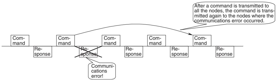
Operation with the number of retrial nodes set
Note
(1) Setting the number of retrial nodes makes MC Unit reserve the time in the cycle time for the specified number of retries.
(Even without any communications error or retries, the processing time for them is added to the cycle time.)
(2) This setting closely relates to the communications cycle. For details, see 1-7 Performance Calculation Method for Communications Cycle on page 22.
| No. | Address in MC Unit | Name | Type | Unit | Immediate updating |
| P00010 | 5009h | MECHATROLINK-II delay in com-munication start | Data | --- | No |
| Data configuration 31 Delay in communications start | Setting range 00000000 to 0000EA60 Hex (0 to 60000) | Initial value 00000000 (0) | |||
Explanation
-
Specifies the time to make the communication start delayed in order to wait for slave startup.
-
A period of time set here is waited for after the power to the MC Unit has been turned ON, and then starts communications with the slaves.
| No. | Address in MC Unit | Name | Type | Unit | Immediate updating |
| P00011 | 500Ah | Number of zone bits | Data | --- | No |
| Data configuration 31 00 Number of zone bits | Setting range 00000000 to 00000020 Hex (0 to 32) | Initial value 00000000 (0) | |||
Explanation
- Set 1 to 32 zone bits.
- In Pn0012, set the leading address for the zone data (upper and lower limits) for which the zone bits are to be used.
- If 0 is set for Pn00011, zone bits will not be used.
- For details on zone bit operations, refer to 9-7 Zones.
| No. | Address in MC Unit | Name | Type | Unit | Immediate updating | |
| P00012 | 500Bh | Zone data leading address | Data | --- | No | |
| Data configuration31 16 15 00Variable type Address | Initial value | |||||
| 00000000 (0) | ||||||
Explanation
- Set the leading address for the zone data for the zone bits that are to be used.
Note Zone data is made of long words (32 bits).
| Bits | Function and explanation |
| 00 to 15 | Address Sets the leading address for the specified variable. Refer to the variable type for the address range. 0000 to 0FFF (0 to 4,095) |
| 16 to 31 | Variable type Sets the variable area for setting the zone data. 0002: Global general purpose variables (Address range: 0000 to 1FFC Hex) 0003: Input variables (address range: 0000 to 0FFC Hex) 0004: Output variables (address range: 0000 to 0FFC Hex) 0005: Position data (address range: 0000 to 27FE Hex) 0006: Task variable 1 (address range: 0000 to 007C Hex) 0007: Task variable 2 (address range: 0000 to 007C Hex) 0008: Task variable 3 (address range: 0000 to 007C Hex) 0009: Task variable 4 (address range: 0000 to 007C Hex) 000A: Task variable 5 (address range: 0000 to 007C Hex) 000B: Task variable 6 (address range: 0000 to 007C Hex) 000C: Task variable 7 (address range: 0000 to 007C Hex) 000D: Task variable 8 (address range: 0000 to 007C Hex) |
Example: With two zone bits (P00011 = 2) , make the following settings to set
zone data for position data PL0000 to PL0003.
P0012 = 00050000 Hex
| Position data | Name and description | |
| PL0000 | Zone 1 lower limit | Zone data |
| PL0001 | Zone 1 upper limit | |
| PL0002 | Zone 2 lower limit | |
| PL0003 | Zone 2 upper limit | |
| PL0004 | Position data used by program | |
| : | : | |
| : | : | |
- To save zone data to the F-ROM in the MC Unit, set the zone data to position data with the variable type set to position data.
Position data can be saved to F-ROM using the Support Tool or a save command from the ladder program.
Motion Task Parameters
Note Abbreviation in the No. column: M = 1 - 8 (motion task number)
Abbreviation in the address column: M = 0 - 7 (motion task number-1)
| No. | Address in MC Unit | Name | Type | Unit | Immediate updating |
| P00M01 | 5020h + (M * 20h) | Max. interpolation feed rate | Data | Command unit/min | Yes |
| Data configuration Setting range 00000001 to 7FFFFFFHex 00002710 (10000) 31 Max. interpolation feed rate | Initial value | ||||
| 00002710 (10000) | |||||
Explanation
- This parameter sets the max. interpolation feed rate. (Operand F)
The max speed is limited by (32767 command unit/unit scan).
P00M01 [command unit/min] ≤ 1966020000/Ts [ms]
Ts [s]: Unit scan time
This indicates the unit cycle time of MC Unit determined by the numbers of tasks, axes, parallel branches, and refreshed words.
1966020000:
The upper limit of speed resolution is 32767 [command unit/unit scan]. The value 1966020000 is obtained by converting 32767 [command unit/unit scan] to the unit of minutes (32767 × 60 × 1000) .
Note The setting of this parameter limits the speed changed with override and the speed specified with Operand F.
| No. | Address in MC Unit | Name | Type | Unit | Immediate updating |
| P00M02 | 5021h + (M * 20h) | Interpolation feed acceleration time | Data | ms | Yes |
| Data configuration Setting range | Initial value | ||||
| 31 | 00 | 00000000 to 0000EA60 Hex (0 to 60000) | 00000064 (100) | ||
| Acceleration time | |||||
Explanation
Pass Mode (P00M06) = 0 or 1
Sets the time required to accelerate from zero to the feed rate specified in the interpolation command.
Pass Mode (P00M06) = 2 or 3
Sets the time required to accelerate from zero to the maximum interpolation feed rate (P00M06).
Note
(1) Enabling S-curve filter causes the delay for the S-curve time constant.
(2) This parameter cannot be changed during operation.
(3) For details of Accel/decel patterns, see 6-1-5 Axis Movement Operation (Page 248).
| No. | Address in MC Unit | Name | Type | Unit | Immediate updating |
| P00M03 | 5022h + (M * 20h) | Interpolation feed deceleration time | Data | ms | Yes |
| Data configuration Setting range | Initial value | ||||
| 31 | 00 | 00000000 to 0000EA60 Hex (0 to 60000) | 00000064 (100) | ||
| Deceleration time | |||||
Explanation
Pass Mode (P00M06) = 0 or 1
Sets the time required to decelerate from the feed rate specified in the interpolation command to zero.
Pass Mode (P00M06) = 2 or 3
Sets the time required to decelerate from the maximum interpolation feed rate (P00M06) to zero.
Note
(1) Enabling S-curve filter causes the delay for the S-curve time constant.
(2) This parameter cannot be changed during operation.
(3) For details of Accel/decel patterns, see 6-1-5 Axis Movement Operation (Page 248).
| No. | Address in MC Unit | Name | Type | Unit | Immediate updating |
| P00M04 | 5023h + (M * 20h) | Interpolation S-curve filter enabled | Data | --- | Yes |
| Data configuration Setting range 00000000 to 00000001 Hex 00 (0 to 1) | Initial value | ||||
| 00000000 (0) | |||||
| S-curve filter enabled | |||||
Explanation
Select enabled/disabled of S-curve filter at the interpolation feed rate.
0: Disabled (Symmetrical)
1: Enabled (S-curve)
Note For details of Accel/decel patterns, see 6-1-5 Axis Movement Operation (Page 248).
| No. | Address in MC Unit | Name | Type | Unit | Immediate updating |
| P00M05 | 5024h + (M * 20h) | Interpolation S-curve time constant | Data | ms | Yes |
| Data configuration Setting range | Initial value | ||||
| 31 | 00 | 00000000 to 00007530 Hex (0 to 30000) | 00000064 (100) | ||
| S-curve time constant | |||||
Explanation
Sets the S-curve filter time constant at the interpolation feed rate.
| No. | Address in MC Unit | Name | Type | Unit | Immediate updating |
| P00M06 | 5025h + (M * 20h) | Pass mode select | Data | --- | No |
| Data configuration Setting range | Initial value | ||||
| 31 | 00 | 00000000 to 00000003 Hex (0 to 3) | 00000000 (0) | ||
| Pass mode select | |||||
Explanation
Sets the combination of the interpolation Accel/decel time and Pass mode with fixed acceleration enabled/disabled.
0: Interpolation acceleration time + Pass mode with fixed acceleration disabled
1: Interpolation deceleration time + Pass mode with fixed acceleration disabled
2: Interpolation acceleration time + Pass mode with fixed acceleration enabled
3: Interpolation deceleration time + Pass mode with fixed acceleration enabled
Note
(1) 2 and 3 are enabled when specifying only 1 axis with MOVEL command.
(2) Interpolation override in Pass mode with fixed acceleration is disabled during deceleration caused by insufficient remaining travel distance.
(3) Pass mode with fixed acceleration cannot complete the passing operation under the following condition. After a deceleration stop, the next operation is executed.
Distance required for deceleration stop from current speed > Travel distance of the next block
(4) The bank switching method for acceleration and deceleration times can be selected for unit version 3.1 and later by switching P0004 (unit function selection) bit 13 (interpolation acceleration/deceleration bank switching option).
0: Selects the same banks for acceleration and deceleration times.
1: Selects different banks for acceleration and deceleration times.
MOVEL, MOVEC, and MOVETRAV can be specified separately. Enabled for both pass mode and stop mode.
(5) There are several acceleration/deceleration times that can be used in the pass operation. For details, see 6-1-5 Axis Movement Operation (Page 248).
| No. | Address in MC Unit | Name | Type | Unit | Immediate updating |
| P00M07 | 5026h + (M * 20h) | Initial modal data 1 MOVE command value select | Data | --- | No |
| Data configuration Setting range 00000000 to 00000001 Hex 00 (0 to 1) | Initial value | ||||
| 00000000 (0) | |||||
| 31 MOVecommand value select | |||||
Explanation
Specifies the initial value if ABS/INC specification has been omitted in a motion program.
0: ABL (Operation is executed defining the target position as the absolute position.)
1: INC (Operation is executed defining the target position as the relative position.)
| No. | Address in MC Unit | Name | Type | Unit | Immediate updating |
| P00M08 | 5027h + (M * 20h) | Initial modal data 2 Operating mode select | Data | --- | No |
| Data configuration Setting range | Initial value | ||||
| 31 | 00 | 00000000 to 00000001 Hex (0 to 1) | 00000000 (0) | ||
| Operating mode select | |||||
Explanation
Specifies the initial value if PASSMODE/STOPMODE specification has been omitted in a motion program.
0: Operation is executed in Pass mode.
1: Operation is executed in Stop mode.
| No. | Address in MC Unit | Name | Type | Unit | Immediate updating |
| P00M09 | 5028h + (M * 20h) | Initial modal data 3 Interpolation feed rate | Data | Command unit/ min | No |
| Data configuration Setting range 00000001 to 7FFFFFFHex 00000001 to 7FFFFFFHex 1 to 2147483647) | Initial value | ||||
| 00002710 (10000) | |||||
| Interpolation feed rate | |||||
Explanation
- Specifies the initial value if interpolation feed rate (F command) has been omitted in a motion program.
The max speed is limited by (32767 command unit/unit scan).
P00M09 [command unit/min] ≤ 1966020000/Ts [ms]
Ts[s]: Unit scan time
This indicates the unit cycle time of MC Unit determined by the numbers of tasks, axes, parallel branches, and refreshed words.
1966020000:
The upper limit of speed resolution is 32767 [command unit/unit scan]. The value 1966020000 is obtained by converting 32767 [command unit/unit scan] to the unit of minutes (32767 × 60 × 1000) .
| No. | Address in MC Unit | Name | Type | Unit | Immediate updating |
| P00M10 | 5029h + (M * 20h) | Interpolation feed decimal point position | Data | --- | No |
| Data configuration Setting range 00000000 to 00000004 Hex 00 (0 to 4) | Initial value | ||||
| 00000000 (0) | |||||
| 31 | |||||
| Interpolation feed decimal point position | |||||
Explanation
Sets the method of interpreting the speed command value specified by an immediate value with a decimal point.
0:×1
1:×10
2:×100
3:×1000
4:×10000
Ex) When controlling X-axis with task 1 and selecting × 10 of interpolation feed decimal point position (P00M10) for task 1,
MOVEL [J01]100.00 F100.;
is processed as,
MOVEL [J01]100.00 F1000;
Note The following notations have the same meaning when Interpolation feed decimal point position (P00M10) is × 10 .
Please note that they are treated differently from position command values.
MOVEL [J01]100.00 F1000;
MOVEL [J01]100.00 F100.;
MOVEL [J01]100.00 F100.0;
| No. | Address in MC Unit | Name | Type | Unit | Immediate updating |
| P00M11 to P00M20 | 502Ah + (M * 20h) to 5033h + (M * 20h) | P00004 bit 13 = 0 • Interpolation feed acceleration/ deceleration times banks 1 to 10. | Data | ms | Yes |
| P00004 bit 13 = 1 • Interpolation feed acceleration time banks 1 to 5. Interpolation feed deceleration time banks 1 to 5. | |||||
| The bank switching method for acceleration and deceleration times can be selected for unit version 3.1 and later by switching P0004 (unit function selection) bit 13 (interpolation acceleration/deceleration bank switching option). | |||||
| 1. P00004 bit 13 = 0 Selects the same banks for acceleration and deceleration times. | Initial value | ||||
| Data configuration | Setting range | 00000064 (100) | |||
| 31 | 00 | 00000000 to 0000EA60 Hex (0 to 60000) | |||
| Interpolation feed acceleration/deceleration bank 1 to 10 | |||||
Explanation
They set the acceleration/deceleration times for interpolation feeding (MOVEL, MOVEC, and MOVETRAV).
The following variables are provided and the bank number for each task can be specified by substituting it for the variable to switch the acceleration/deceleration time to be used.
| Variable | Bits | Name |
| IW0A00 | 00 to 15 | Acceleration/deceleration bank selection for motion task 1 (initial value: 0) |
| IW0A01 | 00 to 15 | Acceleration/deceleration bank selection for motion task 2 (initial value: 0) |
| IW0A02 | 00 to 15 | Acceleration/deceleration bank selection for motion task 3 (initial value: 0) |
| IW0A03 | 00 to 15 | Acceleration/deceleration bank selection for motion task 4 (initial value: 0) |
| IW0A04 | 00 to 15 | Acceleration/deceleration bank selection for motion task 5 (initial value: 0) |
| IW0A05 | 00 to 15 | Acceleration/deceleration bank selection for motion task 6 (initial value: 0) |
| IW0A06 | 00 to 15 | Acceleration/deceleration bank selection for motion task 7 (initial value: 0) |
| IW0A07 | 00 to 15 | Acceleration/deceleration bank selection for motion task 8 (initial value: 0) |
Setting range for acceleration/deceleration bank selections:
1 to 10: Select the acceleration/deceleration time in banks 1 to 10.
Other: Selects P00M02 (interpolation feed acceleration time) and
P00M03 (interpolation feed deceleration time).
The setting of system parameter P00M06 (pass mode select) determines whether the value is used as the acceleration time or as the deceleration time.
P00M06 = 0 or 2: Used as acceleration time.
P00M06 = 1 or 3: Used as deceleration time.
Refer to Operating Mode under 6-1 Basic Information (Page 252) for details.
- P00004 bit 13 = 1 (Supports unit version 3.1 and later)
Selects different banks for acceleration and deceleration times.
Data configuration
31
1615
Interp
Isolation feed deceleration
time banks 1 to 5
Interpolation acceleration time banks 1 to 5
Explanation
Sets the acceleration/deceleration times for interpolation feeding (MOVEL, MOVEC, and MOVETRAV). The following variables are provided and the bank number for each task can be specified by substituting it for the variable to switch the acceleration/deceleration time to be used.
| Variable | Bits | Name |
| IW0A00 | 00 to 15 | Acceleration bank selection for motion task 1 (initial value: 100) |
| IW0A01 | 00 to 15 | Acceleration bank selection for motion task 2 (initial value: 100) |
| IW0A02 | 00 to 15 | Acceleration bank selection for motion task 3 (initial value: 100) |
| IW0A03 | 00 to 15 | Acceleration bank selection for motion task 4 (initial value: 100) |
| IW0A04 | 00 to 15 | Acceleration bank selection for motion task 5 (initial value: 100) |
| IW0A05 | 00 to 15 | Acceleration bank selection for motion task 6 (initial value: 100) |
| IW0A06 | 00 to 15 | Acceleration bank selection for motion task 7 (initial value: 100) |
| IW0A07 | 00 to 15 | Acceleration bank selection for motion task 8 (initial value: 100) |
| IW0A08 | 16 to 31 | Deceleration bank selection for motion task 1 (initial value: 100) |
| IW0A09 | 16 to 31 | Deceleration bank selection for motion task 2 (initial value: 100) |
| IW0A0A | 16 to 31 | Deceleration bank selection for motion task 3 (initial value: 100) |
| IW0A0B | 16 to 31 | Deceleration bank selection for motion task 4 (initial value: 100) |
| IW0A0C | 16 to 31 | Deceleration bank selection for motion task 5 (initial value: 100) |
| IW0A0D | 16 to 31 | Deceleration bank selection for motion task 6 (initial value: 100) |
| IW0A0E | 16 to 31 | Deceleration bank selection for motion task 7 (initial value: 100) |
| IW0A0F | 16 to 31 | Deceleration bank selection for motion task 8 (initial value: 100) |
Setting range for interpolation feed acceleration time:
1 to 5 P00M11 to P00M15 are used for the interpolation feed acceleration time.
Other P00M02 is used for the interpolation feed acceleration time.
1 to 5 P00M16 to P00M20 are used for the interpolation deceleration time.
Other P00M03 uses interpolation the feed deceleration time.
Setting range for interpolation feed deceleration time:
Use of the acceleration or deceleration times is permanently enabled regardless of the state of system parameter P00M06 (pass mode option). Refer to Operating Mode under 6-1 Basic Information (Page 252) for details.
| No. | Address in MC Unit | Name | Type | Unit | Immediate updating |
| P00M21 | 5034h + (M * 20h) | Number of parallel branches in each task | Data | --- | No |
| Data configuration Setting range | Initial value | ||||
| 31 | 00 | 00000000 to 00000008 Hex (0 to 8) | 00000000 (0) | ||
| Number of parallel branches | |||||
Explanation
- Set the number of parallel branches to be used for task number M (1 to 32) and the number of commands (1 to 8) to be executed simultaneously.
- This parameter is enabled when P00004 bit 11 is ON.
- The Unit cycle is determined by the number of tasks used, the number of axes, the number of parallel branches, and the number of words in the general allocation. For information on these relative expressions, refer to 1-7 Performance. The Unit cycle can be shortened by using this parameter when required by the application.
Note When P00M21 is set to 0, the number of parallel branches for the task will be processed as 1 even if P00004 bit 11 is ON.
Axis-Allocation Parameters
Note Abbreviation in the No. column: AA = 1 to 32 (axis number) Abbreviation in the address column: AA = 0 to 31 (axis number - 1)
| No. | Address in MC Unit | Name | Type | Unit | Immediate updating |
| P1AA01 | 5340h + (AA * 14h) | Physical axis setting | Data | --- | No |
| Data configuration Setting range | Initial value | ||||
| 31 | 00 | 00000000 to 00000020 Hex (0 to 32) | 00000000 (0) | ||
| Physical axis setting | |||||
Explanation
Sets the usage of the physical axes (J01 to J32) to be used with MCH.
| Setting | Description |
| 00000000 Hex (0) | Not used as physical axes. |
| 00000001 to0000001E Hex (1 to 30) | These axes are used as real axes.MECHATROLINK-II devices are used for real axes.Sets the node addresses of MECHATROLINK-II devices Node addresses of MECHATROLINK-II devices 1 to 30 correspond to the setting values 1 to 30. |
| 00000020 Hex (32) | This axis is used as a virtual axis. |
| Other than the above | ReservedDo not set. |
Note
(1) For details of the differences between the virtual axis and the actual axis, see 6-1-13 Virtual Axis (Page 282).
(2) This setting relates to the unit cycle and communications cycle. For details, see 1-7 Performance Calculation Method for Unit Cycle, Calculation Method for Communications Cycle on page 22.
| No. | Address in MC Unit | Name | Type | Unit | Immediate updating |
| P1AA02 | 5341h + (AA * 14h) | MECHATROLINK-II device classi-fication | Data | --- | No |
| Data configuration Setting range | Initial value | ||||
| 31 | 00 | 00000000, 00000064 Hex(0, 100) | 00000000 (0) | ||
| Classification | |||||
Explanation
Sets the types of devices connected as MECHATROLINK-II slaves.
| Setting | Explanation |
| 00000000 Hex (0) | A Servo Driver is used. |
| 00000064 Hex (100) | I/O, counter, and pulse output modules are used as an I/O axis. |
| Other than the above | Reserved Do not set. |
Note
For details of differences between axes allocated as I/O and servo axes, see 6-1-14 I/O Axis (page 283).
| No. | Address in MC Unit | Name | Type | Unit | Immediate updating |
| P1AA03 | 5342h + (AA * 14h) | Input allocation points (No. of words) | Data | 16 points (word) | No |
| Data configuration Setting range | Initial value | ||||
| 31 | 00 | 00000000 to 0000000F Hex (0 to 15) | 00000000 (0) | ||
| Input allocation points | |||||
Explanation
Specifies the No. of points (words) for input signals of MECHATROLINK-II slave nodes allocated to input variables of MC Unit.
Note
With only 1 axis, words for the No. of words specified in the input variable IW0010 are allocated and they link with the inputs of MECHATROLINK-II slave nodes.
| No. | Address in MC Unit | Name | Type | Unit | Immediate updating |
| P1AA04 | 5343h + (AA * 14h) | Output allocation points (No. of words) | Data | 16 points (word) | No |
| Data configuration Setting range 00000000 to 0000000F Hex 00 (0 to 15) | Initial value | ||||
| 00000000 (0) | |||||
| 31 Output allocation points | |||||
Explanation
Specifies the No. of points (words) for output signals of MECHATROLINK-II slave nodes allocated to output variables of MC Unit.
Note With only 1 axis, words for the No. of words specified in the output variable OW0010 are allocated and they link with the outputs of MECHATROLINK-II slave nodes.
| No. | Address in MC Unit | Name | Type | Unit | Immediate updating | |
| P1AA05 | 5344h + (AA * 14h) | Axis allocation first address | Data | --- | No | |
| Data configuration | Initial value | |||||
| 31 | 16 | 15 | 00 | 00000000 (0) | ||
| Variable type | Address | |||||
Explanation
- When using MECHATROLINK-II counter module or pulse output module as a physical axis, the present position of these counters can be output to the feedback position in the current coordinate system (address SL0200 for axis 1) of the applicable physical axis. Some modules have 2 counters, however, only 1 counter can be specified.
- Sets the address of the Counter present position to be output to the present position.
- The Counter present position is stored in the input variable area allocated in Input allocation points.
| Bit | Explanation |
| 00 to 15 | Specifies the first address. 0000 to 0FFF Hex (0 to 4095) |
| 16 to 31 | Specifies whether the present position is imported or not. 0000 Hex (0): Counter's feedback position in the current coordinate system (address SL0200 for axis 1) is not imported into the physical axes. 0001 Hex (1): Counter's feedback position in the current coordinate system (address SL0200 for axis 1) is imported. |
| No. | Address in MC Unit | Name | Type | Unit | Immediate updating |
| P1AA06 | 5345h + (AA * 14h) | MECHATROLINK-II communica-tions error detection | Data | --- | No |
| Data configuration Setting range | Initial value | ||||
| 31 | 00 | 00000000 to 00000005 Hex(0 to 5) | 00000000 (0) | ||
| Communications error detection | |||||
Explanation
Sets the No. of allowable times of communications errors on MECHA-TROLINK-II device.
The setting of this parameter is valid only for I/O (specified in P1AA02: MECHATROLINK-II device classification).
When the allowable times set here are exceeded, [300Bh: Communications alarm] will occur.
| No. | Address in MC Unit | Name | Type | Unit | Immediate updating |
| P1AA07 | 5346h + (AA * 14h) | Reserved | Data | --- | No |
| Data configuration | Initial value | ||||
| 31 | 00 | 00000000 (0) | |||
| Reserved | |||||
Explanation
Reserved
Axis-Speed Parameters
Note Abbreviation in the No. column: AA = 1 to 32 (axis number) Abbreviation in the address column: AA = 0 to 31 (axis number - 1)
| No. | Address in MC Unit | Name | Type | Unit | Immediate updating |
| P2AA01 | 55C0h + (AA * 14h) | Max. rapid feed rate | Data | Command unit/ min | Yes |
| Data configuration Setting range 00000001 to 7FFFFFFHex 31 00 (1 to 2147483647) Max. rapid feed rate | Initial value | ||||
| 00002710 (10000) | |||||
Explanation
- Sets the maximum speed on machine's side for when operating with commands, such as MOVE, MOVEL commands, etc., that include interpolation.
The maximum rapid feed rate can be set using the following calculation formula:
P2AA01 [command unit/min] = P5AA04 [command unit/1 machine rotation] × Max. No. of motor rotations [rotation/min] × P5AA06 [machine rotation speed]/P5AA05 [motor rotation speed]
The maximum speed is limited by (32767 command unit/unit scan).
P2AA01 [command unit/min] ≤ 1966020000/ Ts [ms]
Ts[s]: Unit scan time
This indicates the unit cycle time of MC Unit determined by the numbers of tasks, axes, parallel branches, and refreshed words.
1966020000:
The upper limit of speed resolution is 32767 [command unit/unit scan]. The value 1966020000 is obtained by converting 32767 [command unit/unit scan] to the unit of minutes (32767 × 60 × 1000) .
Note The setting of this parameter limits the speed changed by override, the speed specified by Operand V of MOVEI command, the speed changed by override in MOVET command.
| No. | Address in MC Unit | Name | Type | Unit | Immediate updating |
| P2AA02 | 55C1h + (AA * 14h) | Max. manual feed rate | Data | Command unit/ min | Yes |
| Data configuration Setting range 00000001 to 7FFFFFFHex 31 00 (1 to 2147483647) Max. manual feed rate | Initial value 00002710 (10000) | ||||
Explanation
Sets the maximum speed on machine's side when operating with JOG, STEP operations, and DATUM command.
The max speed is limited by (32767 command unit/unit scan).
Note The setting of this parameter limits the speed changed by override.
| No. | Address in MC Unit | Name | Type | Unit | Immediate updating |
| P2AA03 | 55C2h + (AA * 14h) | Rapid feed rate | Data | Command unit/ min | Yes |
| Data configuration Setting range 00000001 to 7FFFFFFHex 00000001 to 7FFFFFFHex 00000001 to 7FFFFFFHex 00000001 to 7FFFFFFHex 00000001 to 7FFFFFFHex 00000001 to 7FFFFFFHex 00000001 to 7FFFFFFHex 00000001 to 7FFFFFFHex 1 to 2147483647) | Initial value | ||||
| 31 Rapid feed rate | 00002710 (10000) | ||||
Explanation
Sets the speed (a value with override 100% ) on machine's side for when operating with MOVE, MOVEI commands.
The max speed is limited by (32767 command unit/unit scan).
Note Speed can be changed during operation using override.
| No. | Address in MC Unit | Name | Type | Unit | Immediate updating |
| P2AA04 | 55C3h + (AA * 14h) | Manual feed rate | Data | Command unit/ min | Yes |
| Data configuration Setting range00000001 to 7FFFFFFHex00002710 (10000)31 Manual feed rate | Initial value | ||||
| 00002710 (10000) | |||||
Explanation
Sets the speed (a value with override 100% ) on machine's side for when performing JOG and STEP operations.
The max speed is limited by (32767 command unit/unit scan).
Note Speed can be changed during operation using override.
| No. | Address in MC Unit | Name | Type | Unit | Immediate updating |
| P2AA05 | 55C4h + (AA * 14h) | Rapid feed acceleration time | Data | ms | Yes |
| Data configuration Setting range | Initial value | ||||
| 31 | 00 | 00000000 to 0000EA60 Hex (0 to 60000) | 00000064 (100) | ||
| Acceleration time | |||||
Explanation
Sets the time required to accelerate from zero to max. rapid feed rate.
Note (1) Enabling S-curve filter causes the delay for the S-curve time constant.
(2) This parameter cannot be changed during operation.
| No. | Address in MC Unit | Name | Type | Unit | Immediate updating |
| P2AA06 | 55C5h + (AA * 14h) | Rapid feed deceleration time | Data | ms | Yes |
| Data configuration Setting range | Initial value | ||||
| 31 | 00 | 00000000 to 0000EA60 Hex (0 to 60000) | 00000064 (100) | ||
| Deceleration time | |||||
Explanation
Sets the time required to decelerate from max. rapid feed rate to zero.
Note (1) Enabling S-curve filter causes the delay for the S-curve time constant.
(2) This parameter cannot be changed during operation.
| No. | Address in MC Unit | Name | Type | Unit | Immediate updating |
| P2AA07 | 55C6h + (AA * 14h) | Manual feed acceleration time | Data | ms | Yes |
| Data configuration Setting range 00000000 to 0000EA60 Hex 00 (0 to 60000) | Initial value | ||||
| 00000064 (100) | |||||
| Acceleration time | |||||
Explanation
Sets the time required to accelerate from zero to max. manual feed rate.
Note (1) Enabling S-curve filter causes the delay for the S-curve time constant.
(2) This parameter cannot be changed during operation.
(3) For details of Accel/decel patterns, see 6-1-5 Axis Movement Operation (Page 248).
| No. | Address in MC Unit | Name | Type | Unit | Immediate updating |
| P2AA08 | 55C7h + (AA * 14h) | Manual feed deceleration time | Data | ms | Yes |
| Data configuration Setting range 00000000 to 0000EA60 Hex 00 (0 to 60000) | Initial value | ||||
| 00000064 (100) | |||||
| Deceleration time | |||||
Explanation
Sets the time required to decelerate from max. manual feed rate to zero.
Note (1) Enabling S-curve filter causes the delay for the S-curve time constant.
(2) This parameter cannot be changed during operation.
(3) For details of Accel/decel patterns, see 6-1-5 Axis Movement Operation (Page 248).
| No. | Address in MC Unit | Name | Type | Unit | Immediate updating |
| P2AA09 | 55C8h + (AA * 14h) | Rapid feed S-curve filter enabled | Data | --- | No |
| Data configuration Setting range 00000000 to 00000001 Hex 00 (0 to 1) | Initial value | ||||
| 00000000 (0) | |||||
| S-curve filter enabled | |||||
Explanation
Selects the S-curve filter enable/disable at rapid feed rate.
0:Disabled
1: Enabled
Note For details of Accel/decel patterns, see 6-1-5 Axis Movement Operation (Page 248).
| No. | Address in MC Unit | Name | Type | Unit | Immediate updating |
| P2AA10 | 55C9h + (AA * 14h) | Manual feed S-curve filter enabled | Data | --- | Yes |
| Data configuration Setting range 00000000 to 00000001 Hex 00 (0 to 1) | Initial value | ||||
| 00000000 (0) | |||||
| S-curve filter enabled | |||||
Explanation
Selects the S-curve filter enable/disable at manual feed rate.
0:Disabled
1: Enabled
Note For details of Accel/decel patterns, see 6-1-5 Axis Movement Operation (Page 248).
| No. | Address in MC Unit | Name | Type | Unit | Immediate updating |
| P2AA11 | 55CAh + (AA * 14h) | Rapid feed S-curve time constant | Data | ms | Yes |
| Data configuration Setting range00000000 to 00007530 Hex0 to 30000) | Initial value | ||||
| 00 | 00000064 (100) | ||||
| S-curve time constant | |||||
Explanation
Sets the S-curve filter time constant at rapid feed rate.
Note For details of Accel/decel patterns, see 6-1-5 Axis Movement Operation (Page 248).
| No. | Address in MC Unit | Name | Type | Unit | Immediate updating |
| P2AA12 | 55CBh + (AA * 14h) | Manual feed S-curve time constant | Data | ms | Yes |
| Data configuration Setting range00000000 to 00007530 Hex00000064 (100) | |||||
| S-curve time constant | |||||
Explanation
Sets the S-curve filter time constant at manual feed rate.
Note For details of Accel/decel patterns, see 6-1-5 Axis Movement Operation (Page 248).
Axis-Position Parameters
Note Abbreviation in the No. column: AA = 1 to 32 (axis number)
Abbreviation in the address column: AA = 0 to 31 (axis number - 1)
| No. | Address in MC Unit | Name | Type | Unit | Immediate updating |
| P3AA01 | 5840h + (AA * 14h) | STEP operation travel distance | Data | Command unit | Yes |
| Data configuration Setting range00000000 to 7FFFFFFHex0 (0 to 2147483647) | Initial value | ||||
| 000003E8 (1000) | |||||
| Travel distance | |||||
Explanation
Sets the travel distance for STEP operation.
| No. | Address in MC Unit | Name | Type | Unit | Immediate updating |
| P3AA02 | 5841h + (AA * 14h) | Positive direction software limit | Data | Command unit | No |
| Data configuration Setting range | Initial value | ||||
| 31 | 00 | 80000000 to 7FFFFFFHex(-2147483648 to 2147483647) | 7FFFFFF(2147483647) | ||
| + direction software limit | |||||
Explanation
Sets the software limit value in the positive direction.
An error will occur when the command value created in every unit scan exceeds this software limit.
The value has to satisfy the following conditions:
P3AA02 [command unit] = + direction upper limit/minimum setting unit
P3AA03 [command unit] = - direction upper limit/minimum setting unit
P3AA03 < P3AA02
Ex) When positioning X-axis (ball screw) in 0.01 mm unit (P5AA01, P5AA2)
within -100 to 100mm , the following values are to be set:
P3AA02 = 100mm/0.01 mm = 10000 [command unit]
P3AA03 = -100mm/0.01 mm = -10000 [command unit]
Note The setting of this parameter is ignored in the following cases:
- When Software limit enabled/disabled (P3AA04) is set to either 0 or 2.
- When an origin has not been defined.
- When Axis feed mode (P5AA07) is set to 0010h (unlimited length).
| No. | Address in MC Unit | Name | Type | Unit | Immediate updating |
| P3AA03 | 5842h + (AA * 14h) | Negative direction software limit | Data | Command unit | No |
| Data configuration Setting range | Initial value | ||||
| 31 | 00 | 80000000 to 7FFFFFFHex (-2147483648 to 2147483647) | 80000000 (-2147483648) | ||
| - direction software limit | |||||
Explanation
Sets the software limit value in the negative direction.
An error will occur when the command value created in every unit scan is smaller than this software limit.
(See the setting example of P3AA02: + direction software limit on page 89.)
Note The setting of this parameter is ignored in the following cases:
- When Software limit enabled/disabled (P3AA04) is set to either 0 or 2.
- When an origin has not been defined.
- When Axis feed mode (P5AA07) is set to 0010h (unlimited length).
| No. | Address in MC Unit | Name | Type | Unit | Immediate updating |
| P3AA04 | 5843h + (AA * 14h) | Software limit enabled/disabled | Data | --- | No |
| Data configuration Setting range 00000000 to 00000003 Hex 00 (0 to 3) | Initial value | ||||
| 00000000 (0) | |||||
| 31 | |||||
| Software limit enabled/disabled | |||||
Explanation
Sets whether software limit is enabled or disabled.
0: Disabled in both directions, + and -
1: Enabled only in + direction
2: Enabled only in - direction
3: Enabled in both directions, + and -
Note For details of software limit, see 9-3 Coordinate System (Page 558).
| No. | Address in MC Unit | Name | Type | Unit | Immediate updating |
| P3AA05 | 5844h + (AA * 14h) | Error warning value | Data | Pulse | Yes |
| Data configuration Setting range | Initial value | ||||
| 31 | 00 | 00000000 to 7FFFFFFHex (0 to 2147483647) | 7FFFFFF (2147483647) | ||
| Warning value | |||||
Explanation
Sets the No. of error pulses that causes warning.
The error counter warning bit will turn ON if the position error exceeds the value set in this parameter.
Note Setting this parameter to 0 disables warning detection.
| No. | Address in MC Unit | Name | Type | Unit | Immediate updating |
| P3AA06 | 5845h + (AA * 14h) | Position error alarm detection value | Data | Pulse | Yes |
| Data configuration Setting range00000000 to 7FFFFFFHex0 to 2147483647)Alarm detection value | Initial value | ||||
| 7FFFFFF(2147483647) | |||||
Explanation
Sets the No. of error pulses that causes alarm.
Note Setting this parameter to 0 disables alarm detection.
| No. | Address in MC Unit | Name | Type | Unit | Immediate updating |
| P3AA07 | 5846h + (AA * 14h) | No. 2 in-position range | Data | Pulse | Yes |
| Data configuration Setting range | Initial value | ||||
| 31 | 00 | 00000000 to 0000FFFF Hex (0 to 65535) | 0000FFFF (65535) | ||
| No. 2 in-position range | |||||
Explanation
Sets the range for turning ON the positioning completed signal of interpolation feed in Stop mode.
Note For details, see 6-1-5 Axis Movement Operation (Page 248).
| No. | Address in MC Unit | Name | Type | Unit | Immediate updating |
| P3AA08 | 5847h + (AA * 14h) | Reserved | Data | --- | No |
| Data configuration | Initial value | ||||
| 31 | 00 | 00000000 (0) | |||
| Reserved | |||||
Explanation
Reserved
| No. | Address in MC Unit | Name | Type | Unit | Immediate updating |
| P3AA09 | 5848h + (AA * 14h) | Position control switching speed | Data | 0.01% | Yes |
| Data configuration Setting range | Initial value | ||||
| 31 | 00 | 00000000 to 00007FFF Hex (0 to 32767) | 00000000 (0) | ||
| Position control switching speed | |||||
Explanation
For torque control, specifies the feedback speed at which to return from torque control to position control (when using the TORQUR command) as a percentage of the motor's rated speed.
For speed control, specifies the feedback speed at which to return from speed control to position control (when using the SPEEDR command) as a percentage of the motor's rated speed.
If 0 is set, position control will be returned to at a feedback speed of 0.
Ex) Torque Control
The following example is for a motor rated speed of 3,000 r/min and a position control switching speed of 1000 (in increments of 0.01% , i.e., 10% ).
TORQUE [J01] 100 T100;
:
TORQUER [J01] T100; Outputs from a torque of 100% to a MOVE [J01] 10000; torque of 0% .
Switches to position control mode when the motor speed reaches 300 r/min or lower (i.e., 3,000 r/min × 10%). After returning to position mode, the system waits for the positioning complete flag to turn ON. When the positioning completed flag turns ON, the next command (MOVE) is executed.
Axis-Origin Parameters
Note Abbreviation in the No. column: AA = 1 to 32 (axis number)
Abbreviation in the address column: AA = 0 to 31 (axis number - 1)
| No. | Address in MC Unit | Name | Type | Unit | Immediate updating |
| P4AA01 | 5AC0h + (AA * 14h) | Origin search method | Data | --- | No |
| Data configuration Setting range 00000000 to 00000003 Hex 00 (0 to 3) | Initial value | ||||
| 00000001 (1) | |||||
| Origin search method | |||||
Explanation
Sets the origin search method.
| Setting | Explanation |
| 0 | Origin at power ON The motor position at powering ON is automatically defined as the origin. If an origin search is performed in this mode, the starting position of the origin search is defined as an origin. |
| 1 | Limit reversal Input of the limit input signal during an origin search reverses the operation. After starting an origin search in the origin search start direction at the origin search feed rate, the speed is changed to the origin search approach speed at the rise of the origin proximity input signal (Norrally Open contact). At the rise of the origin determine signal after the fall of the origin proximity input signal, the speed changes to the origin search creep speed to travel for the final interval and finally an origin is established. |
| 2 | 2-level speed in 1 direction Origin search is executed only in 1 direction. After starting an origin search in the phase-Z detection direction at the origin search approach speed, the speed changes to the origin search creep speed at the rise of the origin determine signal input to travel for the final interval and an origin is determined. Inputting the limit input signal before inputting the origin determine input signal activates the alarm. |
| 3 | 3-level speed in 1 direction Origin search is executed only in 1 direction. After starting an origin search in the phase-Z detection direction at the origin search feed rate, the speed is changed to the origin search approach speed at the rise of the origin proximity input signal (Normally Open contact). At the rise of the origin determine signal input after the fall of the origin proximity signal input, the speed changes to the origin search creep speed to travel for the final interval and finally an origin is established. Inputting the limit input signal before inputting the origin proximity input signal activates the alarm. |
Note For details of origin search operations, see SECTION 8 Establishing the Origin (Page 532).
| No. | Address in MC Unit | Name | Type | Unit | Immediate updating |
| P4AA02 | 5AC1h + (AA * 14h) | Origin search start direction | Data | --- | No |
| Data configuration Setting range | Initial value | ||||
| 31 | 00 | 00000000 to 00000001 Hex (0 to 1) | 00000000 (0) | ||
| Origin search start direction | |||||
Explanation
Sets the origin search start direction for the origin search method 1 (Limit reversal).
0: Same as the phase-Z detection direction
1: Opposite to the phase-Z detection direction
Note The setting of this parameter is ignored in other origin search methods.
| No. | Address in MC Unit | Name | Type | Unit | Immediate updating |
| P4AA03 | 5AC2h + (AA * 14h) | Phase-Z (Phase-C) detection direction | Data | --- | No |
| Data configuration Setting range | Initial value | ||||
| 31 | 00 | 00000000 to 00000001 Hex (0 to 1) | 00000000 (0) | ||
| Phase-Z (Phase-C) detection direction | |||||
Explanation
Sets the phase-Z (phase-C) detection direction for origin search methods 1, 2, and 3 (other than 0:Origin at power ON).
0: + direction
1: - direction
Note The setting of this parameter is ignored in the origin search method 0: Origin at power ON.
| No. | Address in MC Unit | Name | Type | Unit | Immediate updating |
| P4AA04 | 5AC3h + (AA * 14h) | Origin deceleration method | Data | --- | No |
| Data configuration Setting range 00000000 to 00000001 Hex 00 (0 to 1) | Initial value | ||||
| 00000000 (0) | |||||
| Origin deceleration method | |||||
Explanation
Sets whether to use the origin proximity input signal or the limit input signal as the origin deceleration signal for origin search methods 1: Limit reversal and 3: 3-level speed in 1 direction.
0: Uses the origin proximity input signal as the origin deceleration signal.
1: Uses CW and CCW as the origin deceleration signal.
Note The setting of this parameter is ignored in origin search methods 0: Origin at power ON and 2: 2-level speed in 1 direction.
| No. | Address in MC Unit | Name | Type | Unit | Immediate updating |
| P4AA06 | 5AC5h + (AA * 14h) | Origin determine signal | Data | --- | No |
| Data configuration Setting range 00000000 to 00000003 Hex 00 (0 to 3) | Initial value | ||||
| 00000000 (0) | |||||
| Origin determine signal | |||||
Explanation
Specifies the signal to determine (latch) an origin.
0: Defines the phase-Z (phase-C) as an origin
1: Defines the external input signal 1 as an origin
2: Defines the external input signal 2 as an origin
3: Defines the external input signal 3 as an origin
Note The setting of this parameter is ignored in the origin search method 0: Origin at power ON.
| No. | Address in MC Unit | Name | Type | Unit | Immediate updating |
| P4AA07 | 5AC6h + (AA * 14h) | Origin search feed rate | Data | Command unit/ min | Yes |
| Data configuration Setting range 00000001 to 7FFFFFFHex 31 00 (1 to 2147483647) | Initial value | ||||
| 00002710 (10000) | |||||
| Feed rate | |||||
Explanation-
Sets the speed of the 1st level for 3-level speed origin search.
The maximum speed is limited by (32767 command unit/unit scan).
| No. | Address in MC Unit | Name | Type | Unit | Immediate updating |
| P4AA08 | 5AC7h + (AA * 14h) | Origin search approach speed | Data | Command unit/ min | Yes |
| Data configuration Setting range00000001 to 7FFFFFFHex000003E8 (1000) | Initial value | ||||
| 31 | 00 | (1 to 2147483647) | 000003E8 (1000) | ||
| Approach speed | |||||
Explanation
Sets the speed of the 2nd level for 3-level speed origin search, or sets the speed of the 1st level for 2-level speed origin search.
The maximum speed is limited by (32767 command unit/unit scan).
| No. | Address in MC Unit | Name | Type | Unit | Immediate updating |
| P4AA09 | 5AC8h + (AA * 14h) | Origin search creep speed | Data | Command unit/ min | Yes |
| Data configuration Setting range 00000001 to 7FFFFFFHex 31 00 (1 to 2147483647) | Initial value | ||||
| 00000064 (100) | |||||
| Creep speed | |||||
Explanation
Sets the speed of the 3rd level for 3-level speed origin search, or sets the speed of the 2nd level for 2-level speed origin search.
The maximum speed is limited by (32767 command unit/unit scan).
| No. | Address in MC Unit | Name | Type | Unit | Immediate updating |
| P4AA10 | 5AC9h + (AA * 14h) | Reference (Machine) origin offset | Data | Command unit/ min | Yes |
| Data configuration Setting range 31 00 80000000 to 7FFFFFFHex (-2147483648 to 2147483647) | Initial value | ||||
| 00000000 (0) | |||||
| Offset amount | |||||
Explanation
Sets the offset amount (except for DATUM command) in an origin search.
(The present position after an origin search is recognized as the position (the value) preset in this parameter.)
Note In the origin search with DATUM command, the setting of this parameter is ignored. Instead, the operand (offset value) in the command is used.
| No. | Address in MC Unit | Name | Type | Unit | Immediate updating |
| P4AA11 | 5ACAh + (AA * 14h) | Origin search final travel distance | Data | Command unit/ min | Yes |
| Data configuration Setting range00000000 to 7FFFFFFHex00000000 (0 to 2147483647) | Initial value | ||||
| 00000000 (0) | |||||
| Travel distance | |||||
Explanation
Sets the final travel distance in origin searches.
After the rise of the origin determine signal, the axis travels in the direction specified in P4AA03: Phase-Z (Phase-C) detection direction for the distance specified in this parameter.
Note This is the travel distance after the rise of the origin determine signal. Therefore, make sure that the final travel distance does not exceed the positions of limit input signals. (Otherwise, the alarm [3010h: Over travel reverse alarm] will occur.)
| No. | Address in MC Unit | Name | Type | Unit | Immediate updating |
| P4AA12 | 5ACBh + (AA * 14h) | ABS origin offset | Data | Command unit | Yes |
| Data configuration Setting range | Initial value | ||||
| 31 | 00 | 80000000 to 7FFFFFFHex(-2147483648 to 2147483647) | 00000000 (0) | ||
| Offset amount | |||||
Explanation
Sets the offset amount for ABS origin setting.
When the ABS origin setting bit is turned ON, the compensation value of the absolute encoder is saved to the F-ROM in MC Unit. Simultaneously, the present position on the machine coordinate system is preset to the setting value in this parameter.
Axis-Machine Parameters
Note Abbreviation in the No. column: AA = 1 to 32 (axis number)
Abbreviation in the address column: AA = 0 to 31 (axis number - 1)
| No. | Address in MC Unit | Name | Type | Unit | Immediate updating |
| P5AA01 | 5D40h + (AA * 14h) | Units | Data | --- | No |
| Data configuration Setting range | Initial value | ||||
| 31 | 00 | 00000000 to 00000003 Hex (0 to 3) | 00000000 (0) | ||
| Units | |||||
Explanation
Sets the unit for displaying present positions.
0: mm
1:inch
2: deg
3: pulse
Units for positioning are specified in the parameters P5AA01 and P5AA02.
Ex) Positioning X-axis (ball screw) in 0.01 mm unit.
Positioning Y-axis (turn table) in 0.01 deg unit.
| No. | Address in MC Unit | Name | Type | Unit | Immediate updating |
| P5AA02 | 5D41h + (AA * 14h) | Position command decimal point position | Data | --- | No |
| Data configuration Setting range 00000000 to 00000004 Hex 00 Position command decimal point position | Initial value | ||||
| 00000003 (3) | |||||
Explanation
Sets the method of interpreting the position command specified by an immediate value with a decimal point.
0:1
1:0.1
2:0.01
3:0.001
4:0.0001
Note When pulse is selected for the unit, this parameter is treated as 0.
- When a position command value has a decimal point, processing is as follows:
Ex 1) When the decimal point position of the position command value for X-axis is 1:
MOVE [J01]100.0;
is processed as,
MOVE [J01]100;
Ex 2) When the decimal point position of the X-axis position command value for X-axis is 0.01:
MOVE [J01]100.0;
is processed as,
MOVE [J01]10000;
Note The following notations have the same meaning.
MOVE [J01]100.00;
MOVE [J01]100.000;
MOVE [J01]100.;
If there is no decimal point in the position command value, it is used unaltered.
- When specifying a position command value with a variable using real data of the data access size, the decimal point position set in this parameter is used for processing.
Ex) When the decimal point position of the position command value for X-axis is 0.01:
MF1000 = 123.4567;
MOVE [J01]MF1000;
is processed as,
MOVE [J01]12345;
| No. | Address in MC Unit | Name | Type | Unit | Immediate updating |
| P5AA03 | 5D42h + (AA * 14h) | Speed command decimal point position | Data | --- | No |
| Data configuration Setting range | Initial value | ||||
| 31 | 00 | 00000000 to 00000004 Hex (0 to 4) | 00000000 (0) | ||
| Speed command decimal point position | |||||
Explanation
Sets the method of interpreting the speed command specified by an immediate value with a decimal point.
0:×1
1:×10
2:×100
3:×1000
4:×10000
Ex) When controlling X-axis with task 1 and the speed command decimal point position (P5AA03) for task 1 is × 10 :
MOVEI [J01]100.00 D2000.0 V100.;
is processed as,
MOVEI [J01]100.00 D2000.0 V1000;
Note The following notations have the same meaning when Speed command decimal point position (P5AA03) is × 10 .
Please note that they are treated differently from position command values.
MOVEI [J01]100.00 D2000.0 V1000;
MOVEI [J01]100.00 D2000.0 V100.;
MOVEI [J01]100.00 D2000.0 V100.0;
| No. | Address in MC Unit | Name | Type | Unit | Immediate updating |
| P5AA04 | 5D43h + (AA * 14h) | Command unit/1 machine rotation | Data | Command unit | No |
| Data configuration Setting range 00000001 to 7FFFFFFHex 00002710 (10000) | |||||
| 31 Command unit/1 machine rotation (1 to 2147483647) | |||||
Explanation
Sets the resolution of a command for 1 machine rotation.
(The value set here is treated as command units.)
Ex) When positioning X-axis (ball screw with the lead of 10mm ) in 0.01mm unit (P5AA01, P5AA02), the resolution is, 10mm / 0.01mm = 1000 [command unit/1 machine rotation]
Ex) When positioning Y-axis (turn table of 360 deg per rotation) in 0.01 deg unit (P5AA01, P5AA02), the resolution is, 360 deg/0.01 deg = 36000 [command unit/1 machine rotation]
Note
(1) When pulse is selected for the unit, the setting of this parameter is ignored.
(2) When deg is selected for the unit, set the value that can be obtained by (360 × 10^position command decimal point position) .
(3) When the following formula is not satisfied, the alarm [3040h: Gear ratio range error] will occur. 1 / 2147483647 ≤ (P5AA04 × P5AA06) / (value in the parameter 9001h × P5AA05) ≤ 2147483647
| No. | Address in MC Unit | Name | Type | Unit | Immediate updating |
| P5AA05 | 5D44h + (AA * 14h) | Gear ratio 1 (Motor rotation speed) | Data | Rotation | No |
| Data configuration Setting range | Initial value | ||||
| 31 | 00 | 00000001 to 00989680 Hex (1 to 10000000) | 00000001 (1) | ||
| Gear ratio 1 | |||||
Explanation
Sets the No. of motor rotations related to the gear ratio between motor and machine.
Note
(1) When pulse is selected for the unit, the setting of this parameter is ignored.
(2) When the following formula is not satisfied, the alarm 3040h: Gear ratio range error will occur. 1 / 2147483647 ≤ (P5AA04 × P5AA06) / (value in the parameter 9001h × P5AA05) ≤ 2147483647
(3) For details of the concept of setting gear ratio, see 4-2-4 Concept of Parameters (Page 103).
| No. | Address in MC Unit | Name | Type | Unit | Immediate updating |
| P5AA06 | 5D45h + (AA * 14h) | Gear ratio 2 (Machine rotation speed) | Data | Rotation | No |
| Data configuration Setting range 00000001 to 00989680 Hex 00000001 (1 to 10000000) | Initial value | ||||
| 31 Gear ratio 2 | 00000001 (1) | ||||
Explanation
Sets the No. of machine rotations related to the gear ratio between motor and machine.
Note
(1) When pulse is selected for the unit, the setting of this parameter is ignored.
(2) When the following formula is not satisfied, the alarm 3040h: Gear ratio range error will occur. 1 / 2147483647≤ (P5AA04× P5AA06) / (value in the parameter 9001h× P5AA05) ≤ 2147483647
(3) For details of the concept of setting gear ratio, see 4-2-4 Concept of Parameters (Page 103).
| No. | Address in MC Unit | Name | Type | Unit | Immediate updating | |||||
| P5AA07 | 5D46h + (AA * 14h) | Axis feed mode | Data | --- | No | |||||
| Data configuration31 07 04 0000000000000000000000000000000000000000000000000000000000000000000000000000000000000000000000000000 | Initial value | |||||||||
| 000000000 (0) | ||||||||||
Explanation
| Bit | Function and explanation |
| 00 to 03 | Reserved |
| 04 to 07 | Sets the method of managing the coordinate system for position commands. 0: Limited length (On the mechanical configuration, the axis has traveling limits.) 1: Unlimited length (On the mechanical configuration, the axis does not have traveling limits.) |
| 08 to 31 | Reserved |
Note For details of coordinate systems corresponding to modes, see 9-3 Coordinate System (Page 558).
| No. | Address in MC Unit | Name | Type | Unit | Immediate updating | ||
| P5AA08 | 5D47h + (AA * 14h) | External input signal select 1 | Data | --- | Yes | ||
| Data configuration31 24 16 08 00W | Initial value00000000 (0) | ||||||
Explanation
- Specifies the external input signal for each function at a latch request.
| Bit | Function and explanation |
| 00 to 07 | Z: Specifies the latch input signal for MOVEI command (Interrupt feeding). |
| 08 to 15 | Y: Specifies the latch input signal for MOVELINK command (Link operation start). |
| 16 to 23 | X: Specifies the latch input signal for CAMBOX command (Cam synchronous start). |
| 24 to 31 | W: Specifies the latch input signal for SYNC command (Trail synchronization start). |
- Setting range: 00 to 03 Hex (0 to 3)
00 Hex (0): Phase-Z (Phase-C) signal is used as the latch request signal.
01 Hex (1): External input signal 1 is used as the latch request signal.
02 Hex (2): External input signal 2 is used as the latch request signal.
03 Hex (3): External input signal 3 is used as the latch request signal.
Note To set this parameter, the input terminal has to be enabled in the servo parameter Pn511.
(It is allocated according to the initial setting; however, it will require special attention when the user has customized the setting of the parameter.)
| No. | Address in MC Unit | Name | Type | Unit | Immediate updating | |
| P5AA09 | 5D48h + (AA * 14h) | External input signal select 2 | Data | --- | Yes | |
| Data configuration | Initial value | |||||
| 31 | 16 | 15 | 00 | 00000000 (0) | ||
| Variable type | Address | |||||
Explanation
- Specifies the external input signal for each function at a latch request.
| Bit | Function and explanation |
| 00 to 07 | X: Specifies the latch input signal for LATCH command (Present position latch). |
| 08 to 31 | Reserved |
- Setting range: 00 to 03 Hex (0 to 3)
00 Hex (0): Phase-Z (Phase-C) signal is used as the latch request signal.
01 Hex (1): External input signal 1 is used as the latch request signal.
02 Hex (2): External input signal 2 is used as the latch request signal.
03 Hex (3): External input signal 3 is used as the latch request signal.
Note To set this parameter, the input terminal has to be enabled in the servo parameter Pn511.
(It is allocated according to the initial setting; however, it will require special attention when the user has customized the setting of the parameter.)
Zone Parameters
Note Abbreviation in the No. column: ZZ = 1 to 32 (axis number)
Abbreviation in the address column: ZZ = 0 to 31 (axis number - 1)
| No. | Address in MC Unit | Name | Type | Unit | Immediate updating | |
| P6ZZ01 | 5FC0h + (ZZ * 2h) | Zone bit reference address | Data | --- | No | |
| Data configuration31 16 15 00Variable type Address | Initial value | |||||
| 00000000 (0) | ||||||
Explanation
Set the address for the variable (such as the feedback present position) that is to be monitored.
The monitored variable is long word (32 bits) data.
The zone bit set in P6ZZ02 will turn ON when the variable value set here is within the zone data range (specified in P00012).
| Bit | Function and explanation |
| 00 to 15 | Address Set the leading address for the specified variable. Refer to the variable type for the address range. 0000 to 0FFF (0 to 4,095) |
| 16 to 31 | Variable type Set the variable area to be referenced by the zone bit. 0001: System variable (address range: 0000 to 07FE Hex) 0002: Global general-purpose variable (address range: 0000 to 1FFE Hex) 0003: Input variable (address range: 0000 to 0FFE Hex) 0004: Output variable (address range: 0000 to 0FFE Hex) 0005: Position data (address range: 0000 to 27FF Hex) 0006: Task variable 1 (address range: 0000 to 007E Hex) 0007: Task variable 2 (address range: 0000 to 007E Hex) 0008: Task variable 3 (address range: 0000 to 007E Hex) 0009: Task variable 4 (address range: 0000 to 007E Hex) 000A: Task variable 5 (address range: 0000 to 007E Hex) 000B: Task variable 6 (address range: 0000 to 007E Hex) 000C: Task variable 7 (address range: 0000 to 007E Hex) 000D: Task variable 8 (address range: 007E Hex) |
Example: To reference position data PL0002, set P6ZZ01 to 0050002 Hex.
| No. | Address in MC Unit | Name | Type | Unit | Immediate updating | |
| P6ZZ02 | 5FC1h + (ZZ * 2h) | Zone bit output address | Data | --- | No | |
| Data configuration31 16 15 00Address Bit | Initial value | |||||
| 00000000 (0) | ||||||
Explanation
-
Set the zone bit to output the monitoring results (ON/OFF).
-
Zone bits are specified by an address and a bit. Only the output variable area can be referenced within the range of the word (16 bits) data.
| Bit | Function and explanation |
| 00 to 15 | Address Set the bit to be turned ON and OFF. 0000 to 000F Hex: 0000 corresponds to bit 0, and 000F cor-re-sponds to bit 15. |
| 16 to 31 | Address Set the output variable address. 0B00 to 0FFF Hex |
To set bit 10 of output variable 0W0010 as a zone bit, set P6ZZ02 to 0010000A Hex.
4-2-4 Concept of Parameters
Gear Ratio
This section explains the concept of the gear ratio.
In case of position command:
In a machine configuration where the motor axis rotation (m) results in the machine axis rotation (n), set the gear ratio as shown below:
[P5AA05: Gear ratio 1 (Motor rotation speed)] = m
[P5AA06: Gear ratio 2 (Machine rotation speed) = n]
Example)
If P5AA05 = 2 and P5AA06 = 1, giving a command to rotate the machine axis at 1000 r/min will make the motor axis rotate at 2000 r/min.
In cases of Speed Command and Torque Command:
Only the SPEED and TORQUE commands can control speed and torque respectively. These commands are for the motor axes, so there is no need to set the gear ratio.
Example)
Even when P5AA05 = 2 and P5AA06 = 1 are set, giving a command to rotate at 1000r/min with the SPEED command will make the motor axis rotate at 1000r/min.
Relations between Command Unit and Pulses
The relations between the command unit on the machine side and pulses on the motor side can be described by the following formulas:
9001h [No. of encoder pulses/ Pulses [on Motor] = Command unit [on Machine] × One motor rotation] × P5AA05 [on Motor] P5AA04 [Command unit/One machine rotation] × P5AA06 [on Machine]
P5AA04 [Command unit/One machine rotation] Command unit [on Machine] = Pulses [on Motor] × P5AA06 [on Machine] 9001h [No. of encoder pulses/ One motor rotation] × P5AA05 [on Motor]
If the following formula cannot be satisfied, the alarm [3040h: Gear ratio range error] will occur.
1/2147483647 ≤ (P5AA04 × P5AA06)/(9001h × P5AA05) (fraction to be reduced) ≤ 2147483647
Command unit limit:
The maximum value of the command unit system has to satisfy the following formula because pulse command system is described with the range in 32-bit:
Command unit limit ≤ Command unit position ≤ Command unit limit
P5AA04 [Command unit/One machine rotation] Command unit limit [on machine] = 2147483647 × P5AA06 [on Machine] [on Motor] 9001h [No. of encoder pulses/ One motor rotation] × P5AA05 [on Motor]
Speed
When specifying a position exceeding the value obtained by the above formula in a program, the alarm [2009h: Position specification error] will occur.
Additionally, the upper limit of the [Command unit limit], 2147483647, will limit the exceeding value.
The speed unit for the position command is the Command unit/min at machine axes.
The overview of the relations between the machine axis speed [command unit/min] and motor axis rotations [r/min] can be described by the following formula.
Motor axis speed [Motor rev/min] = axis speed [Command unit/min]P5AA04 [Command unit/One machine rotation] × 5AA05 [on Motor]P5AA06 [on Machine]
Minimum speed to avoid intermittent output:
Minimum speed command is 1 command unit/unit scan. When outputting slower speed than this, the output will be intermittent on the waveform.
Minimum speed [Command unit/min] = 1 [Command unit/ms] × 60 [sec/min] × 1000 [ms/sec] × unit scan time [ms]
Precision of feedback speed 1 and 2:
Precision of feedback speed 1 and 2 output to the system variable is as follows:
- Precision of feedback speed 1
Feedback speed, based on the unit [pulses/ms], is ultimately converted into the divisions of the minimum speed mentioned above, and will be output.
Therefore, the minimum speed will be the resolution of the feedback speed 1.
Ex) When the unit cycle is 4 [ms]:
$$ \begin{array}{l} \text {M i n i m u m s p e e d} [ \text {c o m m a n d u n i t / m i n} ] = 1 \times 6 0 \times 1 0 0 0 \times 4 \ = 2 4 0 0 0 0 [ \text {c o m m a n d u n i t / m i n} ] \ \end{array} $$
From the above, the feedback speed 1 will change in the unit of 240000 [command units/min].
- Precision of feedback speed 2
Precision of feedback speed [r / min] = 1 [pulses/ms] × 1000× 60 / 9001h [No. of encoder pulses/motor rotation])/unit cycle [ms]
Ex) When encoder resolution is 16 bits [10000h pulses/r] and unit cycle is 4 [ms]:
$$ \begin{array}{l} \text {P r e c i s i o n} = 1 \times 1 0 0 0 \times 6 0 / 6 5 3 6 / 4 \ = 0. 2 2 8 [ \mathrm {r} / \mathrm {m i n} ] = 0. 2 2 [ \mathrm {r} / \mathrm {m i n} ] \ \end{array} $$
From the above, the feedback speed 2 will change in the unit of 0.22 [r/min].
Setting rated 1000 [r/min] when the unit is [%] , it will be in the unit of 0.22/ 1000 = 0.02% .
Speed indication for not causing [A94] when inputting the limit sensor signal:
When the limit sensor signal is input to the servo driver during rotations, the warning [A94: Data Setting Warning] may occur on NS115 due to communications delay. There is no deviation in positioning, yet the speed that causes the alarm is to be explained in the following:
Speed that causes A94 [Command unit/min] = Speed command MAX [Pulse]/delay in Communications cycle [ms] × gear reverse conversion [Command unit/pulse] × 60 [sec/min] × 1000 [ms/sec]
- Speed command MAX: In case of NS115, it is fixed at 32767[pulse].
-
Delay in Communications cycle: No. of times until MC Unit detects the limit sensor signal input (to be converted to Communications cycle) × communications cycle
-
When Communications cycle: Unit Cycle = 1:1, 9 scans
-
When Communications cycle: Unit Cycle = 1:2, 11 scans
Note The delay of the NS115, 2 scans for the uplink and 1 scan for the downlink, is added to the value showed in 1-7 Performance.
- Gear reverse conversion: Previous Pulse a Command unit conversion formula
Example)
When Communications cycle = 1 ms, Unit Cycle = 2 ms (1:2), No. of encoder pulses = 65536
Command unit/One machine rotation = 10000, and gear ratio 1 = gear ratio 2 = 1:
The speed that causes A94 = 32767/11*(10000/65536) × 60 × 1000 = Approximately 27271895 [Command unit/min]
4-2-5 Timing that Enables Transferred System Parameters
Note Make sure to turn the MC Unit power OFF once, and then ON again after system parameters have been transferred. The unit parameters and machine parameters will not change unless the power is turned back ON.
The parameters that are marked 'Yes' on the immediate updating columns can be changed without the power OFF/ON.
- A part of motion task parameters
- Axis - speed parameters
A part of Axis - position parameters - A part of Axis - machine parameters
4-3 Variables
There are six types of MC Unit variables as shown below:
- Position data
- System variables
- Global general variables
- Input variables
Output variables - Task variables
4-3-1 Overview of Variables
| Name | Purpose | Size | Backup to FLASH ROM | R/W | |
| Global variables | |||||
| Position Data | Data to indicate positions. | 10240 positions (40960 byte) | YES | R/W | |
| System vari-ables | Status of MC Unit such as operating modes, error logs, etc. | 2048 words (4096 byte) | NO | R | |
| Global general variables | Can be accessed from all the tasks, and used for Communicating data between oper-ations and tasks. | 8192 words (16384 byte) | NO | R/W | |
| Input variables | Status of the input from CPU Unit or MECHATROLINK-II devices. | 4096 words (8192 byte) | NO | R/W | |
| Output variables | Outputs for CPU Unit or MECHATROLINK-II are executed from a program. | 4096 words (8192 byte) | NO | R or R/W | |
| Variables exclusively for tasks | |||||
| Task variables | Can be used only in each task, and are used as workspace, etc. during operations. | 128 words × 8 tasks (2048 byte) | NO | R/W | |
Note
(1) For Position Data, see 4-4 Position Data (Page 107).
(2) For System variables, see 4-5 System Variables (Page 111).
(3) For Input variables and Output variables, see 4-6 I/O Variables (Page 160).
(4) CAM Data will not be treated as a variable.
Rules for Writing Variables
Use the following format to write variables.
Put # in front of variables.
| # | V | T | hhhh | [b] |
V: Variable type
T: Data access type
hhh: Addresses of Data (in hexadecimal)
b: Bit number for bit-type data access (in hexadecimal)
Example)
PL0000 = 10000;
MOVE[J01]#PL0000;
Variable Type and Address Range
Use 4-digit hexadecimal notation for data addresses.
Data addresses indicate the first address of integer data regardless of the access type.
| Type | Notation | Address range |
| Position Data | PLhhhh | PL0000 - PL27FF |
| System variables | S*hhh | SW0000 - SW07FF |
| Global general variables | M*hhh | MW0000 - MW1FFF |
| Input variables | I*hhh | IW0000 - IW0FFF |
| Output variables | O*hhh | OW0000 - OW0FFF |
| Task variables | D*hhh | DW0000 - DW007F |
Note
Task variables can use 128 words in each task.
Data Access Type
There are four data access types as shown in the following table.
| Type | Notation | Numerical range | Remark |
| Bit type | B | 1 (ON), 0 (OFF) | |
| Integer type | W | -32768 to +32767 (8000 Hex to 7FFF Hex) | Signed word data (16-bit) |
| Double-length integer type | L | -2147483648 to +2147483647 (80000000 Hex to 7FFFFFF Hex) | Signed double-length data (32-bit) |
| Real number type | F | ±(1.175E-38 to 3.402E+38), 0 | Single-precision floating decimal point (32-bit) |
Precautions When Accessing the Same Address with Different Access Type
The variables at the same address share the same physical space.
| The beginning of the global general variable | Bit type | Integer type | Double-length integer type | Real number type |
| MB0000b | MW0000 | ML0000 | MF0000 | |
| MB0001b | MW0001 | |||
| MB0002b | MW0002 | ML0002 | MF0002 | |
| MB0003b | MW0003 |
Note
Odd-number addresses cannot be specified with Double-length integer type or Real number type. Make sure to specify even-number addresses. The position data can be specified with odd-numbers.
Leading address of position data
| Double-length integer type |
| PL0000 |
| PL0001 |
| PL0002 |
| PL0003 |
Followings are the examples:
(1) ML0000 = 1234 --- Write 1234 in the Double-length integer type.
(2) MF0000 = 1234 --- Write 1234 in the real number type.
The variables of the same address share the same physical space even though the types are different. Therefore, the memory image after execution of (1) and (2) will be as described in the table below. If the same address is accessed using a different access type, a different value will be read. So it needs special attention.
| Case | Original value | In hexadecimal | Display in different type |
| (1) | 1234 | 000004D2hex | 1.729202E-042 (Real number type) |
| (2) | 1.234000E+003 | 449A4000hex | 1150959616 (Integer type) |
Bit Specification
If the bit type is selected for data access, the bit position in 16-bit word data needs to be specified with Bit No.
Example) "MB10002" indicates the second bit of MW1000.
There are 10240 of position data that can be used. In a motion program, positioning is executed by specifying a position directly or by specifying a position in the position data (indirect specification). Position data is transferred between an MC Unit and the Support Tool by using the Support Tool (MC-Miel) or IOWR/IORD instructions.
4-4-1 Position Data Address
Specify position data at the following addresses in MC Unit memory. Specify the addresses in hexadecimal when using IOWR/IORD instructions.
| Data | IORD/IOWR control Address range | No. of transferred words |
| Position Data | 0000 to 27FF Hex (deci-mal:0000 to10239) | 1 word: 0002 Hex, 2 words: 0004 Hex, 3 words: 0006 Hex, 4 words: 0008 Hex |
In MC Unit programming, the position data address is specified as a type of variable as shown below:
PL
: Specify 0000 to 27FF as the address No.(Example)
MOVE_[J1]#PL01FF
4-4-2 Position Data Configuration
Each position data is comprised of two words (4 bytes). Though the position data of the MC Unit does not have a decimal point decimal, however, a decimal point is added to the data based on the setting of Position command decimal point position (P5AA02) in Axis-machine parameters.
Data Range
-2147483648 to +2147483647 (80000000 Hex to 7FFFFFFHex)
| 15 | 00 |
| Position Data (Signed 32-bit, lower 16 bits) | |
| Position Data (Signed 32-bit, upper 16 bits) |
Example 1: Position data 12345 (00003039 Hex)
| 15 | 12 | 11 | 08 | 07 | 04 | 03 | 00 | |
| j+0 | 3 | 0 | 3 | 9 | ||||
| j+1 | 0 | 0 | 0 | 0 | ||||
When Units (P5AA01) of Axis-machine parameters is 0: mm and Position command decimal point position (P5AA02) is 3: 0.001, the position data 12345 is handled as 12.345 mm.
Example 2: Position data -12345 (FFFFFFC7 Hex)
| 15 | 12 | 11 | 08 | 07 | 04 | 03 | 00 | |
| j+0 | C | F | C | 7 | ||||
| j+1 | F | F | F | F | ||||
When Units (P5AA01) of Axis-machine parameters is 1: inch and Position command decimal point position (P5AA02) is 2: 0.01, the position data -12345 is handled as -123.45 inch.
4-4-3 Indirect Specification
Indirect specification can be used only for position data.
1,2,3... 1. Add the symbol @ in front of position data, indicating to use the position data specified by the stored data (address).
- As shown below, @PL0001 specifies the stored data 0012 of the position data PL0100.
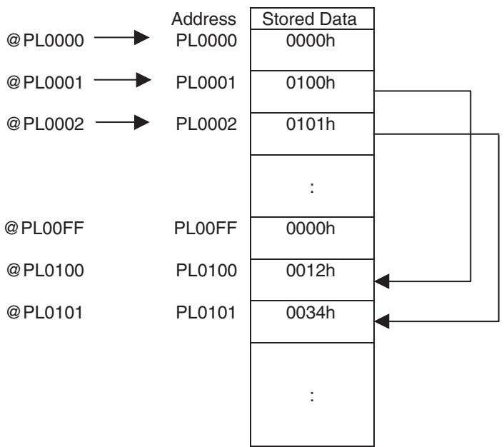
- Indirect specification can be also used as an operand of a command.
Example 1: MOVE_[J1] @PL0100 (= MOVE_[J1]#PL0012)
Example 2: In the above example, #PL0001 = @PL0100+1 has the same meaning as #PL0001 = #PL0012+1.
- Indirect specification can be used for writing as well (Unit Ver. 3.0 or later).
Example: In the above example, @PL0001 = 1 has the same meaning as P0100 = 1.
Indirect specification is always written on the left side (for @PL001 = 1, @PL001 is the left side) for writing.
Indirect specification for writing is enabled only when combined with the following operators.
| Classification | Function | Command |
| Simple Arithmetic | Assign | = |
| Simple Arithmetic | Add | + |
| Simple Arithmetic | Subtract | − |
| Simple Arithmetic | Multiply | * |
| Simple Arithmetic | Divide | / |
| Simple Arithmetic | Quotient | % |
| Simple Arithmetic | Exponent | ^ |
| Logic Operation | OR (Logical OR) | | |
| Logic Operation | XOR (Logical exclusive OR) | ~ |
| Logic Operation | AND (Logical AND) | & |
| Logic Operation | NOT (Reverse) | ! |
Example: @PL0001 = 1000/30;
@PL0002 = #PL0002*10;
Example of incorrect usage: @PL0001 = SIN#MF0010;← Functions cannot be used.
- The address range check is performed when executing the command. If the specified address is outside of the range, the alarm [2003h: Variable address error] will occur and the program will be stopped.
4-4-4 Methods Used to Read, Write and Transfer Position Data
Position data is created or transferred with the following methods.
| No. | Method | Range |
| 1 | Position data is read or written using the IORD or IOWR instruction. | Individual |
| 2 | Data can be loaded and saved using the Support Tool. | All or individual |
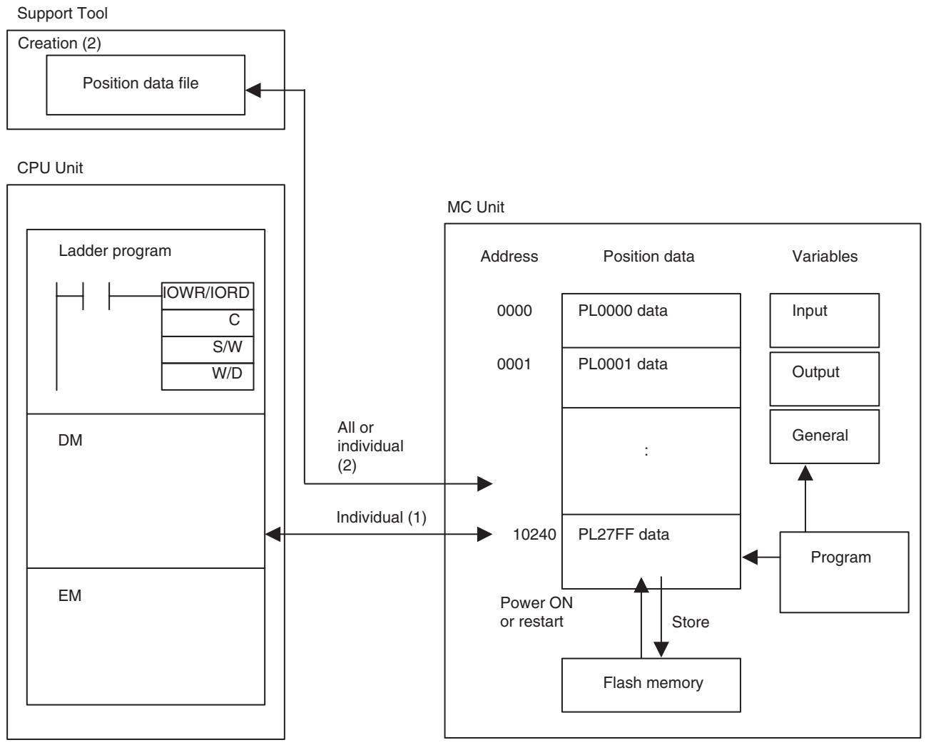
4-5 System Variables
4-5-1 System Variables
System variables are all in read-only area; they cannot be written.
When reading with the IORD instruction, the size is always two words (4 bytes).
| Variable Address | IORD Address | Group | Name | Description | Unit | Update timing |
| SW0000 | 3000 | Unit | Unit Cycle Time | Outputs unit cycle time (SH4). | 0.5 ms | When power is turned ON |
| SW0001 | Unit | MECHATROLINK-II Communication Cycle | Outputs the MECHATROLINK-II Com-munication Cycle. | 0.5 ms | When power is turned ON | |
| SW0002 | 3001 | Unit | Operation Mode | Outputs the MC Unit operation mode 0: RUN mode 1: CPU mode 2: Tool mode | Nil | When operation mode is changed |
| SW0003 | Product ID (Supported in Unit Ver. 3.0 or later) | Bit 00 0: CS1W-MCH71 Unit Ver. 2.0 or earlier 1: Other unit versions | Nil | When power is turned ON | ||
| SW0004 | 3002 | Unit | Forced Stop Request from the Tool: Detail of the request | Indicates forced stop request from the tool. Bit00: Axis: task stop Bit01: Axis, task stop cancel Bit06: Cam Data buffer copy Bit07: Program buffer copy | Nil | FINS: Task Control setting |
| SW0005 | Forced Stop Request from the Tool: Object 1 | Indicates forced stop request from the tool. Bit00-07: 0/1 Motion task 1-8With/without forced stop request Bit08: 0/1 Reserved | Nil | FINS: Task Control Setting | ||
| SW0006 | 3003 | Forced Stop Request from the Tool: Object 2 | Indicates forced stop request from the tool. Bit00-31: 0/1 Axis 1-32With/without forced stop request | Nil | FINS: Task Control Setting | |
| SW0007 | ||||||
| SW0008 | 3004 | Reserved | Reserved | Reserved | Reserved | |
| SW0009 | Status of Forced Stop from the Tool: Object 1 | Indicates status of forced stop from the tool. Bit00-07: 0/1 Motion task 1-8in progress/being stopped Bit08: 0/1 Reserved | Nil | Unit Scan | ||
| SW000A | 3005 | Status of Forced Stop from the Tool: Object 2 | Indicates status of forced stop from the tool. Bit00-31: 0/1 Axis 1-32in progress/being stopped | Nil | Unit Scan | |
| SW000B | ||||||
| SW000C | 3006 | Unit | No. of Unit Scan Execu-tions | Indicates the No. of unit scan execu-tions. | Times | Unit Scan |
| SW000D | ||||||
| SW000E | 3007 | Unit | No. of Self-diagnosis executions | Indicates the No. of self-diagnosis execu-tions in background. | Times | When executing Self-diagnosis |
| SW000F | ||||||
| SW0010 | 3008 | Unit | Error log: No. of stored records | Outputs No. of error logs after the power has been turned ON. 0-20 | Record | Error occurrence |
| SW0011 | Error log: No. of actual records | Outputs No. of error logs after the power has been turned ON. (For system management) 0-64000 The most recent error is stored in the error log whose number is the remain-der of the value output here divided by 20. | Record | Error occurrence | ||
| SW0012 | 3009 | Unit | Error log 1: Error code | Outputs error code of the Error log | Nil | Error occurrence |
| SW0013 | Error log 1: Detailed Information | Outputs detailed information of Error log | Nil | Error occurrence | ||
| SW0014 | 300A | Error log 1: Minute, Second | Outputs the time when error occurred (Minute, Second) | Minute, Second (BCD) | Error occurrence | |
| SW0015 | Error log 1: Day of the Month, Hour | Outputs the time when error occurred (Day of the Month, Hour) | Day of the Month, Hour (BCD) | Error occurrence | ||
| SW0016 | 300B | Error log 1: Year, Month | Outputs the time when error occurred (Year, Month) | Year, Month (BCD) | Error occurrence | |
| SW0017 | Reserved | Reserved | Reserved | Reserved | ||
| SW0018 | 300C | Unit | Error log 2: | Same as for Error log 1 | Same as for Error log 1 | Same as for Error Log 1 |
| SW0019 | ||||||
| SW001A | 300D | |||||
| SW001B | ||||||
| SW001C | 300E | |||||
| SW001D | Reserved | Reserved | Reserved | Reserved | ||
| SW001E | 300F | Unit | Error log 3: | Same as for Error log 1 | Same as for Error log 1 | Same as for Error log 1 |
| SW001F | ||||||
| SW0020 | 3010 | |||||
| SW0021 | ||||||
| SW0022 | 3011 | |||||
| SW0023 | Reserved | Reserved | Reserved | Reserved | ||
| SW0024 | 3012 | Unit | Error log 4: | Same as for Error log 1 | Same as for Error log 1 | Same as for Error log 1 |
| SW0025 | ||||||
| SW0026 | 3013 | |||||
| SW0027 | ||||||
| SW0028 | 3014 | |||||
| SW0029 | Reserved | Reserved | Reserved | Reserved | ||
| SW002A | 3015 | Unit | Error log 5: | Same as for Error log 1 | Same as for Error log 1 | Same as for Error log 1 |
| SW002B | ||||||
| SW002C | 3016 | |||||
| SW002D | ||||||
| SW002E | 3017 | |||||
| SW002F | Reserved | Reserved | Reserved | Reserved | ||
| SW0030 | 3018 | Unit | Error log 6: | Same as for Error log 1 | Same as for Error log 1 | Same as for Error log 1 |
| SW0031 | ||||||
| SW0032 | 3019 | |||||
| SW0033 | ||||||
| SW0034 | 301A | |||||
| SW0035 | Reserved | Reserved | Reserved | Reserved | ||
| SW0036 | 301B | Unit | Error log 7: | Same as for Error log 1 | Same as for Error log 1 | Same as for Error log 1 |
| SW0037 | ||||||
| SW0038 | 301C | |||||
| SW0039 | ||||||
| SW003A | 301D | |||||
| SW003B | Reserved | Reserved | Reserved | Reserved | ||
| SW003C | 301E | Unit | Error log 8: | Same as for Error log 1 | Same as for Error log 1 | Same as for Error log 1 |
| SW003D | ||||||
| SW003E | 301F | |||||
| SW003F | ||||||
| SW0040 | 3020 | |||||
| SW0041 | Reserved | Reserved | Reserved | Reserved | ||
| SW0042 | 3021 | Unit | Error log 9: | Same as for Error log 1 | Same as for Error log 1 | Same as for Error log 1 |
| SW0043 | ||||||
| SW0044 | 3022 | |||||
| SW0045 | ||||||
| SW0046 | 3023 | |||||
| SW0047 | Reserved | Reserved | Reserved | Reserved | ||
| SW0048 | 3024 | Unit | Error log 10: | Same as Error log 1 | Same as for Error log 1 | Same as for Error log 1 |
| SW0049 | ||||||
| SW004A | 3025 | |||||
| SW004B | ||||||
| SW004C | 3026 | |||||
| SW004D | Reserved | Reserved | Reserved | Reserved | ||
| SW004E | 3027 | Unit | Error log 11: | Same as Error log 1 | Same as for Error log 1 | Same as for Error log 1 |
| SW004F | ||||||
| SW0050 | 3028 | |||||
| SW0051 | ||||||
| SW0052 | 3029 | |||||
| SW0053 | Reserved | Reserved | Reserved | Reserved | ||
| SW0054 | 302A | Unit | Error log 12: | Same as for Error log 1 | Same as for Error log 1 | Same as for Error log 1 |
| SW0055 | ||||||
| SW0056 | 302B | |||||
| SW0057 | ||||||
| SW0058 | 302C | |||||
| SW0059 | Reserved | Reserved | Reserved | Reserved | ||
| SW005A | 302D | Unit | Error log 13: | Same as for Error log 1 | Same as for Error log 1 | Same as for Error log 1 |
| SW005B | ||||||
| SW005C | 302E | |||||
| SW005D | ||||||
| SW005E | 302F | |||||
| SW005F | Reserved | Reserved | Reserved | Reserved | ||
| SW0060 | 3030 | Unit | Error log 14: | Same as for Error log 1 | Same as for Error log 1 | Same as for Error log 1 |
| SW0061 | ||||||
| SW0062 | 3031 | |||||
| SW0063 | ||||||
| SW0064 | 3032 | |||||
| SW0065 | Reserved | Reserved | Reserved | Reserved | ||
| SW0066 | 3033 | Unit | Error log 15: | Same as for Error log 1 | Same as for Error log 1 | Same as for Error log 1 |
| SW0067 | ||||||
| SW0068 | 3034 | |||||
| SW0069 | ||||||
| SW006A | 3035 | |||||
| SW006B | Reserved | Reserved | Reserved | Reserved | ||
| SW006C | 3036 | Unit | Error log 16: | Same as for Error log 1 | Same as for Error log 1 | Same as for Error log 1 |
| SW006D | ||||||
| SW006E | 3037 | |||||
| SW006F | ||||||
| SW0070 | 3038 | |||||
| SW0071 | Reserved | Reserved | Reserved | Reserved | ||
| SW0072 | 3039 | Unit | Error log 17: | Same as for Error log 1 | Same as for Error log 1 | Same as for Error log 1 |
| SW0073 | ||||||
| SW0074 | 303A | |||||
| SW0075 | ||||||
| SW0076 | 303B | |||||
| SW0077 | Reserved | Reserved | Reserved | Reserved | ||
| SW0078 | 303C | Unit | Error log 18: | Same as for Error log 1 | Same as for Error log 1 | Same as for Error log 1 |
| SW0079 | ||||||
| SW007A | 303D | |||||
| SW007B | ||||||
| SW007C | 303E | |||||
| SW007D | Reserved | Reserved | Reserved | Reserved | ||
| SW007E | 303F | Unit | Error log 19: | Same as for Error log 1 | Same as for Error log 1 | Same as for Error log 1 |
| SW007F | ||||||
| SW0080 | 3040 | |||||
| SW0081 | ||||||
| SW0082 | 3041 | |||||
| SW0083 | Reserved | Reserved | Reserved | Reserved | ||
| SW0084 | 3042 | Unit | Error log 20: | Same as for Error log 1 | Same as for Error log 1 | Same as for Error log 1 |
| SW0085 | ||||||
| SW0086 | 3043 | |||||
| SW0087 | ||||||
| SW0088 | 3044 | |||||
| SW0089 | Reserved | Reserved | Reserved | Reserved | ||
| SW008A | 3045 | Unit(Unit Ver. 3.0 or later) | Zone setting status bits (No. 1 to No. 16) | Outputs whether the zone bit settings (reference value and output address) are correct. No. 1 corresponds to bit 0, and No. 16 corresponds to bit 15. 0: The zone settings (reference value and output address) are incorrect. 1: The zone settings (reference value and output address) are correct. | Nil | When power is turned ON. |
| SW008B | Zone setting status bits (No. 17 to No. 32) | Outputs whether the zone bit settings (reference value and output address) are correct. No. 17 corresponds to bit 0, and No. 32 corresponds to bit 15. 0: The zone settings (reference value and output address) are incorrect. 1: The zone settings (reference value and output address) are correct. | Nil | When power is turned ON. | ||
| SW008C | 3046 | |||||
| SW008D | ||||||
| SW008E | 3047 | |||||
| SW008F | ||||||
| SW0090 | 3048 | Unit | Clock Data: Minute, Second | Outputs the clock Data (Minute, Second) received from CPU. | Minute, Second (BCD) | In the process of refresh service |
| SW0091 | Unit | Clock Data: Day of the Month, Hour | Outputs the clock Data (Day of the Month, Hour) received from CPU. | Day of the Month, Hour (BCD) | In the process of refresh service | |
| SW0092 | 3049 | Unit | Clock Data: Year, Month | Outputs the clock Data (Year, Hour) received from CPU. | Year, Month (BCD) | In the process of refresh service |
| SW0093 | Unit | Day of the week | Outputs the Clock Data (Day of the Week) received from CPU. | Day of the week (BCD) | In the process of refresh service | |
| SW0094 | 304A | Reserved | Reserved | |||
| SW0095 | Reserved | Reserved | ||||
| SW0096 | 304B | Unit | Reserved | Reserved | Reserved | Reserved |
| SW0097 | ||||||
| SW0098 | 304C | Unit | Release date: Main side: Month, Day Release date: Main side: Year, Tracking code | Displays the system release date (month and day) on the main side. Displays the system release date (year and Tracking code) on the main side. | Month, day (BCD) Year, Tracking code (BCD) | When power is turned ON. When power is turned ON. |
| SW0099 | ||||||
| SW009A | 304D | Unit | Release date: Sub side: month, day Release date: Sub side: Year, Tracking code | Displays the system release date (month and day) on the sub side. Displays the system release date (year and Tracking code) on the sub side. | Month, day (BCD) Year, Tracking code (BCD) | When power is turned ON. When power is turned ON. |
| SW009B | ||||||
| SW009C | 304E | Unit | Reserved | Reserved | Reserved | Reserved |
| SW009D | ||||||
| SW009E | 304F | |||||
| SW009F | ||||||
| SW00A0 | 3050 | |||||
| SW00A1 | ||||||
| SW00A2 | 3051 | Unit | Total No. of programs | Outputs total No. of programs 256 | Program | Always |
| SW00A3 | Remaining No. of pro-grams | Outputs the remaining No. of programs that can be saved 0-256 | Program | Always | ||
| SW00A4 | 3052 | Total memory capacity of the program area | Outputs total memory capacity of the program area 2,097,152 (2MB) | Byte | Always | |
| SW00A5 | ||||||
| SW00A6 | 3053 | Remaining memory capacity of the program area | Outputs remaining memory capacity of the program area 0-2,097,152 (2MB) | Byte | Always | |
| SW00A7 | ||||||
| SW00A8 | 3054 | Total quantities of Cam Data | Outputs the total quantities of Cam Data 32 | Set | Always | |
| SW00A9 | Remaining Quantities of Cam Data | Outputs the remaining quantities of Cam Data that can be stored 0-32 | Set | Always | ||
| SW00AA | 3055 | Total memory capacity of Cam Data area | Outputs the whole memory capacity of Cam Data area 131,072 (128KB) | Byte | Always | |
| SW00AB | ||||||
| SW00AC | 3056 | Remaining memory capacity of Cam Data area | Outputs the remaining memory capacity of Cam Data area 0-131,072 (128KB) | Byte | Always | |
| SW00AD | ||||||
| SW00AE | 3057 | Unit | Allocation valid axis | Indicates the axis whose allocation is valid and recognized by MC Unit. 0-31bit: 1st to 32nd axis 0: invalid/1: valid | Nil | When power is turned ON |
| SW00AF |
Motion Tasks
| Variable Address | IORD Address | Group | Name | Description | Unit | Update timing |
| SW00B0 | 3058 | Motion Task | Task status 1: Main pro-gram No. | Outputs the program No. of the Main Program currently being executed 0-499, 2000 | No. | When a program is started |
| SW00B1 | Task status 1: Sub-pro-gram No. | Outputs the program No. of the Sub-program currently being executed 500-999 | No. | When GOSUB command is being executed | ||
| SW00B2 | 3059 | Task status 1: Single execution command block No.1 | Outputs the block No. of single execu-tion command currently being executed 0 (Not executing), 1-800 | Block | When single execu-tion command is stepping | |
| SW00B3 | Task status 1: Multiple execution command block No.1 | Outputs the block No. of multiple execu-tion command currently being executed 0 (Not executing), 1-800 | Block | When multiple execution command is stepping | ||
| SW00B4 | 305A | Task status 1: Single execution command block No.2 | Outputs the block No. of single execu-tion command in each parallel branch (Not executing), 1-800 | Block | When single execu-tion command is stepping | |
| SW00B5 | Task status 1: Multiple execution command block No.2 | Outputs the block No. of multiple execu-tion command in each parallel branch 0 (Not executing), 1-800 | Block | When multiple execution command is stepping | ||
| SW00B6 | 305B | Task status 1: Single execution command block No.3 | Outputs the block No. of single execu-tion command in each parallel branch 0 (Not executing), 1-800 | Block | When single execu-tion command is stepping | |
| SW00B7 | Task status 1: Multiple execution command block No.3 | Outputs the block No. of multiple execu-tion command in each parallel branch 0 (Not executing), 1-800 | Block | When multiple execution command is stepping | ||
| SW00B8 | 305C | Task status 1: Single execution command block No.4 | Outputs the block No. of single execu-tion command in each parallel branch 0 (Not executing), 1-800 | Block | When single execu-tion command is stepping | |
| SW00B9 | Task status 1: Multiple execution command block No.4 | Outputs the block No. of multiple execu-tion command in each parallel branch 0 (Not executing), 1-800 | Block | When multiple execution command is stepping | ||
| SW00BA | 305D | Task status 1: Single execution command block No.5 | Outputs the block No. of single execu-tion command in each parallel branch 0 (Not executing), 1-800 | Block | When single execu-tion command is stepping | |
| SW00BB | Task status 1: Multiple execution command block No.5 | Outputs the block No. of multiple execu-tion command in each parallel branch 0 (Not executing), 1-800 | Block | When multiple execution command is stepping | ||
| SW00BC | 305E | Task status 1: Single execution command block No.6 | Outputs the block No. of single execu-tion command in each parallel branch 0 (Not executing), 1-800 | Block | When single execu-tion command is stepping | |
| SW00BD | Task status 1: Multiple execution command block No.6 | Outputs the block No. of multiple execu-tion command in each parallel branch 0 (Not executing), 1-800 | Block | When multiple execution command is stepping | ||
| SW00BE | 305F | Task status 1: Single execution command block No.7 | Outputs the block No. of single execu-tion command in each parallel branch 0 (Not executing), 1-800 | Block | When single execu-tion command is stepping | |
| SW00BF | Task status1: Multiple execution command block No.7 | Outputs the block No. of multiple execu-tion command in each parallel branch 0 (Not executing), 1-800 | Block | When multiple execution command is stepping | ||
| SW00C0 | 3060 | Task status 1: Single execution command block No.8 | Outputs the block No. of single execu-tion command in each parallel branch 0 (Not executing), 1-800 | Block | When single execu-tion command is stepping | |
| SW00C1 | Task status1: Multiple execution command block No.8 | Outputs the block No. of multiple execu-tion command in each parallel branch 0 (Not executing), 1-800 | Block | When multiple execution command is stepping | ||
| SW00C2 | 3061 | Breakpoint program number (Unit Ver. 3.0 and later) | Outputs the program No. for which breakpoint is set. 0-999 | Number | When breakpoint is set or cleared | |
| SW00C3 | Breakpoint block num-ber (Unit Ver. 3.0 and later) | Outputs the block No. for which break- point is set. 0 (No breakpoint set), 1-800 | Block | When breakpoint is set or cleared | ||
| SW00C4 | 3062 | Reserved | Reserved | Reserved | Reserved | |
| SW00C5 | ||||||
| SW00C6 | 3063 | |||||
| SW00C7 | ||||||
| SW00C8 | 3064 | |||||
| SW00C9 | ||||||
| SW00CA | 3065 | |||||
| SW00CB | ||||||
| SW00CC | 3066 | |||||
| SW00CD | ||||||
| SW00CE | 3067 | |||||
| SW00CF | ||||||
| SW00D0 | 3068 | Motion task | Task status 2: | Same as for Task status 1 | Same as for Task status 1 | Same as for Task status 1 |
| SW00D1 | ||||||
| SW00D2 | 3069 | |||||
| SW00D3 | ||||||
| SW00D4 | 306A | |||||
| SW00D5 | ||||||
| SW00D6 | 306B | |||||
| SW00D7 | ||||||
| SW00D8 | 306C | |||||
| SW00D9 | ||||||
| SW00DA | 306D | |||||
| SW00DB | ||||||
| SW00DC | 306E | |||||
| SW00DD | ||||||
| SW00DE | 306F | |||||
| SW00DF | ||||||
| SW00E0 | 3070 | |||||
| SW00E1 | ||||||
| SW00E2 | 3071 | |||||
| SW00E3 | ||||||
| SW00E4 | 3072 | Reserved | Reserved | Reserved | Reserved | |
| SW00E5 | ||||||
| SW00E6 | 3073 | |||||
| SW00E7 | ||||||
| SW00E8 | 3074 | |||||
| SW00E9 | ||||||
| SW00EA | 3075 | |||||
| SW00EB | ||||||
| SW00EC | 3076 | |||||
| SW00ED | ||||||
| SW00EE | 3077 | |||||
| SW00EF | ||||||
| SW00F0 | 3078 | Motion task | Task status 3: | Same as for Task status 1: | Same as for Task status 1 | Same as for Task status 1 |
| SW00F1 | ||||||
| SW00F2 | 3079 | |||||
| SW00F3 | ||||||
| SW00F4 | 307A | |||||
| SW00F5 | ||||||
| SW00F6 | 307B | |||||
| SW00F7 | ||||||
| SW00F8 | 307C | |||||
| SW00F9 | ||||||
| SW00FA | 307D | |||||
| SW00FB | ||||||
| SW00FC | 307E | |||||
| SW00FD | ||||||
| SW00FE | 307F | |||||
| SW00FF | ||||||
| SW0100 | 3080 | |||||
| SW0101 | ||||||
| SW0102 | 3081 | |||||
| SW0103 | ||||||
| SW0104 | 3082 | Reserved | Reserved | Reserved | Reserved | |
| SW0105 | ||||||
| SW0106 | 3083 | |||||
| SW0107 | ||||||
| SW0108 | 3084 | |||||
| SW0109 | ||||||
| SW010A | 3085 | |||||
| SW010B | ||||||
| SW010C | 3086 | |||||
| SW010D | ||||||
| SW010E | 3087 | |||||
| SW010F | ||||||
| SW0110 | 3088 | Motion task | Task status 4: | Same as for Task status 1: | Same as for Task status 1 | Same as for Task status 1 |
| SW0111 | ||||||
| SW0112 | 3089 | |||||
| SW0113 | ||||||
| SW0114 | 308A | |||||
| SW0115 | ||||||
| SW0116 | 308B | |||||
| SW0117 | ||||||
| SW0118 | 308C | |||||
| SW0119 | ||||||
| SW011A | 308D | |||||
| SW011B | ||||||
| SW011C | 308E | |||||
| SW011D | ||||||
| SW011E | 308F | |||||
| SW011F | ||||||
| SW0120 | 3090 | |||||
| SW0121 | ||||||
| SW0122 | 3091 | |||||
| SW0123 | ||||||
| SW0124 | 3092 | Reserved | Reserved | Reserved | Reserved | |
| SW0125 | ||||||
| SW0126 | 3093 | |||||
| SW0127 | ||||||
| SW0128 | 3094 | |||||
| SW0129 | ||||||
| SW012A | 3095 | |||||
| SW012B | ||||||
| SW012C | 3096 | |||||
| SW012D | ||||||
| SW012E | 3097 | |||||
| SW012F | ||||||
| SW0130 | 3098 | Motion task | Task status 5: | Same as for Task status 1: | Same as for Task status 1 | Same as for Task status 1 |
| SW0131 | ||||||
| SW0132 | 3099 | |||||
| SW0133 | ||||||
| SW0134 | 309A | |||||
| SW0135 | ||||||
| SW0136 | 309B | |||||
| SW0137 | ||||||
| SW0138 | 309C | |||||
| SW0139 | ||||||
| SW013A | 309D | |||||
| SW013B | ||||||
| SW013C | 309E | |||||
| SW013D | ||||||
| SW013E | 309F | |||||
| SW013F | ||||||
| SW0140 | 30A0 | |||||
| SW0141 | ||||||
| SW0142 | 30A1 | |||||
| SW0143 | ||||||
| SW0144 | 30A2 | Reserved | Reserved | Reserved | Reserved | |
| SW0145 | ||||||
| SW0146 | 30A3 | |||||
| SW0147 | ||||||
| SW0148 | 30A4 | |||||
| SW0149 | ||||||
| SW014A | 30A5 | |||||
| SW014B | ||||||
| SW014C | 30A6 | |||||
| SW014D | ||||||
| SW014E | 30A7 | |||||
| SW014F | ||||||
| SW0150 | 30A8 | Motion task | Task status 6: | Same as for Task status 1: | Same as for Task status 1 | Same as for Task status 1 |
| SW0151 | ||||||
| SW0152 | 30A9 | |||||
| SW0153 | ||||||
| SW0154 | 30AA | |||||
| SW0155 | ||||||
| SW0156 | 30AB | |||||
| SW0157 | ||||||
| SW0158 | 30AC | |||||
| SW0159 | ||||||
| SW015A | 30AD | |||||
| SW015B | ||||||
| SW015C | 30AE | |||||
| SW015D | ||||||
| SW015E | 30AF | |||||
| SW015F | ||||||
| SW0160 | 30B0 | |||||
| SW0161 | ||||||
| SW0162 | 30B1 | |||||
| SW0163 | ||||||
| SW0164 | 30B2 | Reserved | Reserved | Reserved | Reserved | |
| SW0165 | ||||||
| SW0166 | 30B3 | |||||
| SW0167 | ||||||
| SW0168 | 30B4 | |||||
| SW0169 | ||||||
| SW016A | 30B5 | |||||
| SW016B | ||||||
| SW016C | 30B6 | |||||
| SW016D | ||||||
| SW016E | 30B7 | |||||
| SW016F | ||||||
| SW0170 | 30B8 | Motion task | Task status 7: | Same as for Task status 1: | Same as for Task status 1 | Same as for Task status 1 |
| SW0171 | ||||||
| SW0172 | 30B9 | |||||
| SW0173 | ||||||
| SW0174 | 30BA | |||||
| SW0175 | ||||||
| SW0176 | 30BB | |||||
| SW0177 | ||||||
| SW0178 | 30BC | |||||
| SW0179 | ||||||
| SW017A | 30BD | |||||
| SW017B | ||||||
| SW017C | 30BE | |||||
| SW017D | ||||||
| SW017E | 30BF | |||||
| SW017F | ||||||
| SW0180 | 30C0 | |||||
| SW0181 | ||||||
| SW0182 | 30C1 | |||||
| SW0183 | ||||||
| SW0184 | 30C2 | Reserved | Reserved | Reserved | Reserved | |
| SW0185 | ||||||
| SW0186 | 30C3 | |||||
| SW0187 | ||||||
| SW0188 | 30C4 | |||||
| SW0189 | ||||||
| SW018A | 30C5 | |||||
| SW018B | ||||||
| SW018C | 30C6 | |||||
| SW018D | ||||||
| SW018E | 30C7 | |||||
| SW018F | ||||||
| SW0190 | 30C8 | Motion task | Task status 8: | Same as for Task status 1: | Same as for Task status 1 | Same as for Task status 1 |
| SW0191 | ||||||
| SW0192 | 30C9 | |||||
| SW0193 | ||||||
| SW0194 | 30CA | |||||
| SW0195 | ||||||
| SW0196 | 30CB | |||||
| SW0197 | ||||||
| SW0198 | 30CC | |||||
| SW0199 | ||||||
| SW019A | 30CD | |||||
| SW019B | ||||||
| SW019C | 30CE | |||||
| SW019D | ||||||
| SW019E | 30CF | |||||
| SW019F | ||||||
| SW01A0 | 30D0 | |||||
| SW01A1 | ||||||
| SW01A2 | 30D1 | |||||
| SW01A3 | ||||||
| SW01A4 | 30D2 | Reserved | Reserved | Reserved | Reserved | |
| SW01A5 | ||||||
| SW01A6 | 30D3 | |||||
| SW01A7 | ||||||
| SW01A8 | 30D4 | |||||
| SW01A9 | ||||||
| SW01AA | 30D5 | |||||
| SW01AB | ||||||
| SW01AC | 30D6 | |||||
| SW01AD | ||||||
| SW01AE | 30D7 | |||||
| SW01AF | ||||||
| SW01B0 | 30D8 | Tracing (Unit Ver. 3.0 and later) | Trace status 1: Number of trace points | Outputs the number of data trace points set for the trace status. 0 or 128 to 32768 0: Default value or when 0 is set by the Support Tool | Point | When power is turned ON or when trace condition setting is received |
| SW01B1 | Trace status 1: Execution status | Outputs the execution status of the trace operation. 0: Tracing stopped 1: Tracing being executed | Nil | Unit scan | ||
| SW01B2 | 30D9 | Trace status 1: Error information | Outputs error information while tracing is being executed. 0: Normal 1: Trace condition setting error The trace condition setting is incor-rect. | Nil | When the trace start is received | |
| SW01B3 | Trace status 1: Trigger status | Outputs whether or not the trigger condition has been satisfied. 0: Trigger condition not satisfied 1: Trigger condition satisfied | Nil | Unit scan (during trace execution) | ||
| SW01B4 | 30DA | Trace status 1: Sam-pling counter | Outputs the number of times data has been sampled after tracing starts. | Times | Unit scan (during trace execution) | |
| SW01B5 | Trace status 1: Data sampling counter | Outputs the number of times data has been sampled after tracing starts. Delay time is not included. | Times | Unit scan (during trace execution) | ||
| SW01B6 | 30DB | Trace status 2: Number of trace points | Same as for trace status 1. | Same as for trace status 1. | Same as for trace status 1. | |
| SW01B7 | Trace status 2: Execution status | Same as for trace status 1. | Same as for trace status 1. | Same as for trace status 1. | ||
| SW01B8 | 30DC | Trace status 2: Error information | Same as for trace status 1. | Same as for trace status 1. | Same as for trace status 1. | |
| SW01B9 | Trace status 2: Trigger status | Same as for trace status 1. | Same as for trace status 1. | Same as for trace status 1. | ||
| SW01BA | 30DD | Trace status 2: Sam-pling counter | Same as for trace status 1. | Same as for trace status 1. | Same as for trace status 1. | |
| SW01BB | Trace status 2: Data sampling counter | Same as for trace status 1. | Same as for trace status 1. | Same as for trace status 1. | ||
| SW01BC | 30DE | Reserved | Reserved | |||
| SW01BD | ||||||
| SW01BE | 30DF | Reserved | Reserved | |||
| SW01BF | ||||||
| SW01C0 | 30E0 | Reserved | Reserved | |||
| SW01C1 | ||||||
| SW01C2 | 30E1 | Reserved | Reserved | |||
| SW01C3 | ||||||
| SW01C4 | 30E2 | Reserved | Reserved | |||
| SW01C5 | ||||||
| SW01C6 | 30E3 | Reserved | Reserved | |||
| SW01C7 | ||||||
| SW01C8 | 30E4 | Reserved | Reserved | |||
| SW01C9 | ||||||
| SW01CA | 30E5 | Reserved | Reserved | |||
| SW01CB | ||||||
| SW01CC | 30E6 | Reserved | Reserved | |||
| SW01CD | ||||||
| SW01CE | 30E7 | Reserved | Reserved | |||
| SW01CF | ||||||
| SW01D0 | 30E8 | Reserved | Reserved | Reserved | Reserved | |
| SW01D1 | ||||||
| SW01D2 | 30E9 | |||||
| SW01D3 | ||||||
| SW01D4 | 30EA | |||||
| SW01D5 | ||||||
| SW01D6 | 30EB | |||||
| SW01D7 | ||||||
| SW01D8 | 30EC | |||||
| SW01D9 | ||||||
| SW01DA | 30ED | |||||
| SW01DB | ||||||
| SW01DC | 30EE | |||||
| SW01DD | ||||||
| SW01DE | 30EF | |||||
| SW01DF | ||||||
| SW01E0 | 30F0 | |||||
| SW01E1 | ||||||
| SW01E2 | 30F1 | |||||
| SW01E3 | ||||||
| SW01E4 | 30F2 | |||||
| SW01E5 | ||||||
| SW01E6 | 30F3 | |||||
| SW01E7 | ||||||
| SW01E8 | 30F4 | |||||
| SW01E9 | ||||||
| SW01EA | 30F5 | |||||
| SW01EB | ||||||
| SW01EC | 30F6 | Reserved | Reserved | Reserved | Reserved | |
| SW01ED | ||||||
| SW01EE | 30F7 | |||||
| SW01EF | ||||||
| SW01F0 | 30F8 | |||||
| SW01F1 | ||||||
| SW01F2 | 30F9 | |||||
| SW01F3 | ||||||
| SW01F4 | 30FA | |||||
| SW01F5 | ||||||
| SW01F6 | 30FB | |||||
| SW01F7 | ||||||
| SW01F8 | 30FC | |||||
| SW01F9 | ||||||
| SW01FA | 30FD | |||||
| SW01FB | ||||||
| SW01FC | 30FE | |||||
| SW01FD | ||||||
| SW01FE | 30FF | |||||
| SW01FF |
Axis
| Variable Address | IORD Address | Group | Name | Description | Unit | Update timing |
| SW0200 | 3100 | Axis | Axis 1 status: Current Coordinate System FB position | Outputs the FB position on coordinate system currently being selected -2147483648 to 2147483647 | Command unit | Unit scan |
| SW0201 | ||||||
| SW0202 | 3101 | Axis 1 status: Machine Coordinate System FB position | Outputs the FB position on machine coordinate system -2147483648 to 2147483647 | Command unit | Unit scan | |
| SW0203 | ||||||
| SW0204 | 3102 | Axis 1 status: Current Coordinate System Command position | Outputs the command position on coordinate system currently being selected -2147483648 to 2147483647 Same value as FB position on current coordinate system when executing the SPEED or TORQUE commands. | Command unit | Unit scan | |
| SW0205 | ||||||
| SW0206 | 3103 | Axis 1 status: Machine Coordinate System Command position | Outputs the command position on machine coordinate system -2147483648 to 2147483647 Same value as FB position on machine coordinate system when executing the SPEED or TORQUE commands. | Command unit | Unit scan | |
| SW0207 | ||||||
| SW0208 | 3104 | Axis 1 status: Counter latch position | Outputs the counter latch position on machine coordinate system -2147483648 to 2147483647 | Command unit | At latch completion | |
| SW0209 | ||||||
| SW020A | 3105 | Axis 1 status: Feed back Speed 1 | Outputs the FB speed | Command unit/min | Unit scan | |
| SW020B | ||||||
| SW020C | 3106 | Axis 1 status: Feed Back Speed 2 | Outputs the FB speed (% specification of motor rated speed or r/min) The unit is set in bit 2 of P00004. | 0.01% of motor rated speed, or 0.01r/min | Unit scan | |
| SW020D | ||||||
| SW020E | 3107 | Axis | Axis 1 status: Com-mand Speed 1 | Outputs command speedSame value as feedback speed 1 when executing the TORQUE command. | Command unit/min | Unit scan |
| SW020F | ||||||
| SW0210 | 3108 | Axis 1 status: Com-mand Speed 2 | Outputs the command speed (% specifi-cation of motor rated speed or r/min)The unit is set in bit 2 of P00004.Same value as feedback speed 2 when executing the TORQUE command. | 0.01% of motor rated speed, or 0.01r/min | Unit scan | |
| SW0211 | ||||||
| SW0212 | 3109 | Axis 1 status: Errors | Outputs Errors | Pulse | Unit scan | |
| SW0213 | ||||||
| SW0214 | 310A | Axis 1 Status: Torque command value | Outputs Torque command value | 0.01% of Max. motor torque (when Torque com-mand in progress) or, 0.01% of motor rated torque.(When posi-tion/speed In progress) | Unit scan | |
| SW0215 | ||||||
| SW0216 | 310B | Axis 1 status: Work-piece origin shift amount | Outputs the workpiece origin shift amount-2147483648 to 2147483647 | Command unit | When coordinate system is selected | |
| SW0217 | ||||||
| SW0218 | 310C | Axis 1 status: Origin margin in pulses | Outputs the distance between the final change position of the deceleration LS and origin determine signal (phase Z or origin LS).If deceleration LS is not used, outputs 0.-2147483648-2147483647 | Command unit | When origin search is completed | |
| SW0219 | ||||||
| SW021A | 310D | Axis 1 status: Number of multi-turns | Outputs the number of times upper and lower limits on the machine coordinate system are exceeded.ABS encoder: Cleared to 0 at origin setting completion*If Movement exceeding the multi-turns limit is executed it is not guaranteed.INC encoder: Clear to 0 at origin search completion-2147483648 to 2147483647 | Turn | Unit scan | |
| SW021B | ||||||
| SW021C | 310E | Axis 1 status: MECHA-TROLINK-II Servo sta-tus | Servo status: Reflects the MECHA-TROLINK-II servo status. | Nil | Unit scan | |
| SW021D | I/O monitor: Reflects the MECHA-TROLINK-II I/O monitor | |||||
| SW021E | 310F | Axis 1 status: ABS position setting value 1Multi-turns value | ABS encoder multi-turns value at the origin setting. | Turn | When the power is turned ON When ABS setting is completed | |
| SW021F | ||||||
| SW0220 | 3110 | Axis 1 status: ABS position setting value 2No. of Initial incremen-tal pulses | No. of Initial incremental pulses of ABS encoder at the origin setting. | Pulse | When the power is turned ON When ABS setting is complete | |
| SW0221 | ||||||
| SW0222 | 3111 | Reserved | Reserved | Reserved | Reserved | |
| SW0223 | ||||||
| SW0224 | 3112 | |||||
| SW0225 | ||||||
| SW0226 | 3113 | |||||
| SW0227 | ||||||
| SW0228 | 3114 | Axis | Axis 1 status: Command execution status | Outputs the latest command No. See Command Code in Command Execution Status on page 158 | Nil | Unit scan |
| SW0229 | Axis 1 status: Acceleration/deceleration status | Outputs acceleration/deceleration status in relations to real-time target speed including override0: Others (Not moving, during Synchron-ization, etc.)1: Accelerating2: At Constant speed3: Decelerating4: Passing | Nil | Unit scan | ||
| SW022A | 3115 | Axis 1 status: Latch status | Outputs counter latch status0: No latch request1: Parameter being overwritten2: Latch being requested3: Latch completed (next request: disabled)4: Latch completed (next request: enabled)This status has the following influence on OW0440 bit100: SW022A = 0, 1, 21: SW022A = 3, 4 | Nil | Unit scan | |
| SW022B | Axis 1 status: Executing cam table number (Supported in Unit Ver. 3.0 or later) | Outputs the number of the cam table currently executing. The number is output during execution of CAM and CAM-BOX commands.0: Cam table not being executed1 to 32: Cam table number100: Global general variables200: Position dataThen number will be 0 while program execution is interrupted.Negative values indicate reverse order of data number, just like they do in motion programs. | Nil | Unit scan | ||
| SW022C | 3116 | Reserved | Reserved | Reserved | Reserved | |
| SW022D | ||||||
| SW022E | 3117 | |||||
| SW022F | ||||||
| SW0230 | 3118 | Axis | Axis 2 status | Same as for Axis 1 status | Same as for Axis 1 status | Same as for Axis 1 status |
| SW0231 | ||||||
| SW0232 | 3119 | |||||
| SW0233 | ||||||
| SW0234 | 311A | |||||
| SW0235 | ||||||
| SW0236 | 311B | |||||
| SW0237 | ||||||
| SW0238 | 311C | |||||
| SW0239 | ||||||
| SW023A | 311D | |||||
| SW023B | ||||||
| SW023C | 311E | |||||
| SW023D | ||||||
| SW023E | 311F | |||||
| SW023F | ||||||
| SW0240 | 3120 | |||||
| SW0241 | ||||||
| SW0242 | 3121 | |||||
| SW0243 | ||||||
| SW0244 | 3122 | |||||
| SW0245 | ||||||
| SW0246 | 3123 | |||||
| SW0247 | ||||||
| SW0248 | 3124 | |||||
| SW0249 | ||||||
| SW024A | 3125 | |||||
| SW024B | ||||||
| SW024C | 3126 | |||||
| SW024D | ||||||
| SW024E | 3127 | |||||
| SW024F | ||||||
| SW0250 | 3128 | Reserved | Reserved | Reserved | Reserved | |
| SW0251 | ||||||
| SW0252 | 3129 | |||||
| SW0253 | ||||||
| SW0254 | 312A | |||||
| SW0255 | ||||||
| SW0256 | 312B | |||||
| SW0257 | ||||||
| SW0258 | 312C | Axis 2 status | Same as for Axis 1 status | Same as for Axis 1 status | Same as for Axis 1 status | |
| SW0259 | ||||||
| SW025A | 312D | |||||
| SW025B | Reserved | Reserved | Reserved | Reserved | ||
| SW025C | 312E | |||||
| SW025D | ||||||
| SW025E | 312F | |||||
| SW025F | ||||||
| SW0260 | 3130 | Axis | Axis 3 status | Same as for Axis 1 status | Same as for Axis 1 status | Same as for Axis 1 status |
| SW0261 | ||||||
| SW0262 | 3131 | |||||
| SW0263 | ||||||
| SW0264 | 3132 | |||||
| SW0265 | ||||||
| SW0266 | 3133 | |||||
| SW0267 | ||||||
| SW0268 | 3134 | |||||
| SW0269 | ||||||
| SW026A | 3135 | |||||
| SW026B | ||||||
| SW026C | 3136 | |||||
| SW026D | ||||||
| SW026E | 3137 | |||||
| SW026F | ||||||
| SW0270 | 3138 | |||||
| SW0271 | ||||||
| SW0272 | 3139 | |||||
| SW0273 | ||||||
| SW0274 | 313A | |||||
| SW0275 | ||||||
| SW0276 | 313B | |||||
| SW0277 | ||||||
| SW0278 | 313C | |||||
| SW0279 | ||||||
| SW027A | 313D | |||||
| SW027B | ||||||
| SW027C | 313E | |||||
| SW027D | ||||||
| SW027E | 313F | |||||
| SW027F | ||||||
| SW0280 | 3140 | Reserved | Reserved | Reserved | Reserved | |
| SW0281 | ||||||
| SW0282 | 3141 | |||||
| SW0283 | ||||||
| SW0284 | 3142 | |||||
| SW0285 | ||||||
| SW0286 | 3143 | |||||
| SW0287 | ||||||
| SW0288 | 3144 | Axis 3 status | Same as for Axis 1 status | Same as for Axis 1 status | Same as for Axis 1 status | |
| SW0289 | ||||||
| SW028A | 3145 | |||||
| SW028B | Reserved | Reserved | Reserved | Reserved | ||
| SW028C | 3146 | |||||
| SW028D | ||||||
| SW028E | 3147 | |||||
| SW028F | ||||||
| SW0290 | 3148 | Axis | Axis 4 status | Same as for Axis 1 status | Same as for Axis 1 status | Same as for Axis 1 status |
| SW0291 | ||||||
| SW0292 | 3149 | |||||
| SW0293 | ||||||
| SW0294 | 314A | |||||
| SW0295 | ||||||
| SW0296 | 314B | |||||
| SW0297 | ||||||
| SW0298 | 314C | |||||
| SW0299 | ||||||
| SW029A | 314D | |||||
| SW029B | ||||||
| SW029C | 314E | |||||
| SW029D | ||||||
| SW029E | 314F | |||||
| SW029F | ||||||
| SW02A0 | 3150 | |||||
| SW02A1 | ||||||
| SW02A2 | 3151 | |||||
| SW02A3 | ||||||
| SW02A4 | 3152 | |||||
| SW02A5 | ||||||
| SW02A6 | 3153 | |||||
| SW02A7 | ||||||
| SW02A8 | 3154 | |||||
| SW02A9 | ||||||
| SW02AA | 3155 | |||||
| SW02AB | ||||||
| SW02AC | 3156 | |||||
| SW02AD | ||||||
| SW02AE | 3157 | |||||
| SW02AF | ||||||
| SW02B0 | 3158 | Reserved | Reserved | Reserved | Reserved | |
| SW02B1 | ||||||
| SW02B2 | 3159 | |||||
| SW02B3 | ||||||
| SW02B4 | 315A | |||||
| SW02B5 | ||||||
| SW02B6 | 315B | |||||
| SW02B7 | ||||||
| SW02B8 | 315C | Axis 4 status | Same as for Axis 1 status | Same as for Axis 1 status | Same as for Axis 1 status | |
| SW02B9 | ||||||
| SW02BA | 315D | |||||
| SW02BB | Reserved | Reserved | Reserved | Reserved | ||
| SW02BC | 315E | |||||
| SW02BD | ||||||
| SW02BE | 315F | |||||
| SW02BF | ||||||
| SW02C0 | 3160 | Axis | Axis 5 status | Same as for Axis 1 status | Same as for Axis 1 status | Same as for Axis 1 status |
| SW02C1 | ||||||
| SW02C2 | 3161 | |||||
| SW02C3 | ||||||
| SW02C4 | 3162 | |||||
| SW02C5 | ||||||
| SW02C6 | 3163 | |||||
| SW02C7 | ||||||
| SW02C8 | 3164 | |||||
| SW02C9 | ||||||
| SW02CA | 3165 | |||||
| SW02CB | ||||||
| SW02CC | 3166 | |||||
| SW02CD | ||||||
| SW02CE | 3167 | |||||
| SW02CF | ||||||
| SW02D0 | 3168 | |||||
| SW02D1 | ||||||
| SW02D2 | 3169 | |||||
| SW02D3 | ||||||
| SW02D4 | 316A | |||||
| SW02D5 | ||||||
| SW02D6 | 316B | |||||
| SW02D7 | ||||||
| SW02D8 | 316C | |||||
| SW02D9 | ||||||
| SW02DA | 316D | |||||
| SW02DB | ||||||
| SW02DC | 316E | |||||
| SW02DD | ||||||
| SW02DE | 316F | |||||
| SW02DF | ||||||
| SW02E0 | 3170 | Reserved | Reserved | Reserved | Reserved | |
| SW02E1 | ||||||
| SW02E2 | 3171 | |||||
| SW02E3 | ||||||
| SW02E4 | 3172 | |||||
| SW02E5 | ||||||
| SW02E6 | 3173 | |||||
| SW02E7 | ||||||
| SW02E8 | 3174 | Axis 5 status | Same as for Axis 1 status | Same as for Axis 1 status | Same as for Axis 1 status | |
| SW02E9 | ||||||
| SW02EA | 3175 | |||||
| SW02EB | Reserved | Reserved | Reserved | Reserved | ||
| SW02EC | 3176 | |||||
| SW02ED | ||||||
| SW02EE | 3177 | |||||
| SW02EF | ||||||
| SW02F0 | 3178 | Axis | Axis 6 status | Same as for Axis 1 status | Same as for Axis 1 status | Same as for Axis 1 status |
| SW02F1 | ||||||
| SW02F2 | 3179 | |||||
| SW02F3 | ||||||
| SW02F4 | 317A | |||||
| SW02F5 | ||||||
| SW02F6 | 317B | |||||
| SW02F7 | ||||||
| SW02F8 | 317C | |||||
| SW02F9 | ||||||
| SW02FA | 317D | |||||
| SW02FB | ||||||
| SW02FC | 317E | |||||
| SW02FD | ||||||
| SW02FE | 317F | |||||
| SW02FF | ||||||
| SW0300 | 3180 | |||||
| SW0301 | ||||||
| SW0302 | 3181 | |||||
| SW0303 | ||||||
| SW0304 | 3182 | |||||
| SW0305 | ||||||
| SW0306 | 3183 | |||||
| SW0307 | ||||||
| SW0308 | 3184 | |||||
| SW0309 | ||||||
| SW030A | 3185 | |||||
| SW030B | ||||||
| SW030C | 3186 | |||||
| SW030D | ||||||
| SW030E | 3187 | |||||
| SW030F | ||||||
| SW0310 | 3188 | Reserved | Reserved | Reserved | Reserved | |
| SW0311 | ||||||
| SW0312 | 3189 | |||||
| SW0313 | ||||||
| SW0314 | 318A | |||||
| SW0315 | ||||||
| SW0316 | 318B | |||||
| SW0317 | ||||||
| SW0318 | 318C | Axis 6 status | Same as for Axis 1 status | Same as for Axis 1 status | Same as for Axis 1 status | |
| SW0319 | ||||||
| SW031A | 318D | |||||
| SW031B | Reserved | Reserved | Reserved | Reserved | ||
| SW031C | 318E | |||||
| SW031D | ||||||
| SW031E | 318F | |||||
| SW031F | ||||||
| SW0320 | 3190 | Axis | Axis 7 status | Same as for Axis 1 status | Same as for Axis 1 status | Same as for Axis 1 status |
| SW0321 | ||||||
| SW0322 | 3191 | |||||
| SW0323 | ||||||
| SW0324 | 3192 | |||||
| SW0325 | ||||||
| SW0326 | 3193 | |||||
| SW0327 | ||||||
| SW0328 | 3194 | |||||
| SW0329 | ||||||
| SW032A | 3195 | |||||
| SW032B | ||||||
| SW032C | 3196 | |||||
| SW032D | ||||||
| SW032E | 3197 | |||||
| SW032F | ||||||
| SW0330 | 3198 | |||||
| SW0331 | ||||||
| SW0332 | 3199 | |||||
| SW0333 | ||||||
| SW0334 | 319A | |||||
| SW0335 | ||||||
| SW0336 | 319B | |||||
| SW0337 | ||||||
| SW0338 | 319C | |||||
| SW0339 | ||||||
| SW033A | 319D | |||||
| SW033B | ||||||
| SW033C | 319E | |||||
| SW033D | ||||||
| SW033E | 319F | |||||
| SW033F | ||||||
| SW0340 | 31A0 | Reserved | Reserved | Reserved | Reserved | |
| SW0341 | ||||||
| SW0342 | 31A1 | |||||
| SW0343 | ||||||
| SW0344 | 31A2 | |||||
| SW0345 | ||||||
| SW0346 | 31A3 | |||||
| SW0347 | ||||||
| SW0348 | 31A4 | Axis 7 status | Same as for Axis 1 status | Same as for Axis 1 status | Same as for Axis 1 status | |
| SW0349 | ||||||
| SW034A | 31A5 | |||||
| SW034B | Reserved | Reserved | Reserved | Reserved | ||
| SW034C | 31A6 | |||||
| SW034D | ||||||
| SW034E | 31A7 | |||||
| SW034F | ||||||
| SW0350 | 31A8 | Axis | Axis 8 status | Same as for Axis 1 status | Same as for Axis 1 status | Same as for Axis 1 status |
| SW0351 | ||||||
| SW0352 | 31A9 | |||||
| SW0353 | ||||||
| SW0354 | 31AA | |||||
| SW0355 | ||||||
| SW0356 | 31AB | |||||
| SW0357 | ||||||
| SW0358 | 31AC | |||||
| SW0359 | ||||||
| SW035A | 31AD | |||||
| SW035B | ||||||
| SW035C | 31AE | |||||
| SW035D | ||||||
| SW035E | 31AF | |||||
| SW035F | ||||||
| SW0360 | 31B0 | |||||
| SW0361 | ||||||
| SW0362 | 31B1 | |||||
| SW0363 | ||||||
| SW0364 | 31B2 | |||||
| SW0365 | ||||||
| SW0366 | 31B3 | |||||
| SW0367 | ||||||
| SW0368 | 31B4 | |||||
| SW0369 | ||||||
| SW036A | 31B5 | |||||
| SW036B | ||||||
| SW036C | 31B6 | |||||
| SW036D | ||||||
| SW036E | 31B7 | |||||
| SW036F | ||||||
| SW0370 | 31B8 | Reserved | Reserved | Reserved | Reserved | |
| SW0371 | ||||||
| SW0372 | 31B9 | |||||
| SW0373 | ||||||
| SW0374 | 31BA | |||||
| SW0375 | ||||||
| SW0376 | 31BB | |||||
| SW0377 | ||||||
| SW0378 | 31BC | Axis 8 status | Same as for Axis 1 status | Same as for Axis 1 status | Same as for Axis 1 status | |
| SW0379 | ||||||
| SW037A | 31BD | |||||
| SW037B | Reserved | Reserved | Reserved | Reserved | ||
| SW037C | 31BE | |||||
| SW037D | ||||||
| SW037E | 31BF | |||||
| SW037F | ||||||
| SW0380 | 31C0 | Axis | Axis 9 status | Same as for Axis 1 status | Same as for Axis 1 status | Same as for Axis 1 status |
| SW0381 | ||||||
| SW0382 | 31C1 | |||||
| SW0383 | ||||||
| SW0384 | 31C2 | |||||
| SW0385 | ||||||
| SW0386 | 31C3 | |||||
| SW0387 | ||||||
| SW0388 | 31C4 | |||||
| SW0389 | ||||||
| SW038A | 31C5 | |||||
| SW038B | ||||||
| SW038C | 31C6 | |||||
| SW038D | ||||||
| SW038E | 31C7 | |||||
| SW038F | ||||||
| SW0390 | 31C8 | |||||
| SW0391 | ||||||
| SW0392 | 31C9 | |||||
| SW0393 | ||||||
| SW0394 | 31CA | |||||
| SW0395 | ||||||
| SW0396 | 31CB | |||||
| SW0397 | ||||||
| SW0398 | 31CC | |||||
| SW0399 | ||||||
| SW039A | 31CD | |||||
| SW039B | ||||||
| SW039C | 31CE | |||||
| SW039D | ||||||
| SW039E | 31CF | |||||
| SW039F | ||||||
| SW03A0 | 31D0 | Reserved | Reserved | Reserved | Reserved | |
| SW03A1 | ||||||
| SW03A2 | 31D1 | |||||
| SW03A3 | ||||||
| SW03A4 | 31D2 | |||||
| SW03A5 | ||||||
| SW03A6 | 31D3 | |||||
| SW03A7 | ||||||
| SW03A8 | 31D4 | Axis 9 status | Same as for Axis 1 status | Same as for Axis 1 status | Same as for Axis 1 status | |
| SW03A9 | ||||||
| SW03AA | 31D5 | |||||
| SW03AB | Reserved | Reserved | Reserved | Reserved | ||
| SW03AC | 31D6 | |||||
| SW03AD | ||||||
| SW03AE | 31D7 | |||||
| SW03AF | ||||||
| SW03B0 | 31D8 | Axis | Axis 10 status | Same as for Axis 1 status | Same as for Axis 1 status | Same as for Axis 1 status |
| SW03B1 | ||||||
| SW03B2 | 31D9 | |||||
| SW03B3 | ||||||
| SW03B4 | 31DA | |||||
| SW03B5 | ||||||
| SW03B6 | 31DB | |||||
| SW03B7 | ||||||
| SW03B8 | 31DC | |||||
| SW03B9 | ||||||
| SW03BA | 31DD | |||||
| SW03BB | ||||||
| SW03BC | 31DE | |||||
| SW03BD | ||||||
| SW03BE | 31DF | |||||
| SW03BF | ||||||
| SW03C0 | 31E0 | |||||
| SW03C1 | ||||||
| SW03C2 | 31E1 | |||||
| SW03C3 | ||||||
| SW03C4 | 31E2 | |||||
| SW03C5 | ||||||
| SW03C6 | 31E3 | |||||
| SW03C7 | ||||||
| SW03C8 | 31E4 | |||||
| SW03C9 | ||||||
| SW03CA | 31E5 | |||||
| SW03CB | ||||||
| SW03CC | 31E6 | |||||
| SW03CD | ||||||
| SW03CE | 31E7 | |||||
| SW03CF | ||||||
| SW03D0 | 31E8 | Reserved | Reserved | Reserved | Reserved | |
| SW03D1 | ||||||
| SW03D2 | 31E9 | |||||
| SW03D3 | ||||||
| SW03D4 | 31EA | |||||
| SW03D5 | ||||||
| SW03D6 | 31EB | |||||
| SW03D7 | ||||||
| SW03D8 | 31EC | Axis 10 status | Same as for Axis 1 status | Same as for Axis 1 status | Same as for Axis 1 status | |
| SW03D9 | ||||||
| SW03DA | 31ED | |||||
| SW03DB | Reserved | Reserved | Reserved | Reserved | ||
| SW03DC | 31EE | |||||
| SW03DD | ||||||
| SW03DE | 31EF | |||||
| SW03DF | ||||||
| SW03E0 | 31F0 | Axis | Axis 11 status | Same as for Axis 1 status | Same as for Axis 1 status | Same as for Axis 1 status |
| SW03E1 | ||||||
| SW03E2 | 31F1 | |||||
| SW03E3 | ||||||
| SW03E4 | 31F2 | |||||
| SW03E5 | ||||||
| SW03E6 | 31F3 | |||||
| SW03E7 | ||||||
| SW03E8 | 31F4 | |||||
| SW03E9 | ||||||
| SW03EA | 31F5 | |||||
| SW03EB | ||||||
| SW03EC | 31F6 | |||||
| SW03ED | ||||||
| SW03EE | 31F7 | |||||
| SW03EF | ||||||
| SW03F0 | 31F8 | |||||
| SW03F1 | ||||||
| SW03F2 | 31F9 | |||||
| SW03F3 | ||||||
| SW03F4 | 31FA | |||||
| SW03F5 | ||||||
| SW03F6 | 31FB | |||||
| SW03F7 | ||||||
| SW03F8 | 31FC | |||||
| SW03F9 | ||||||
| SW03FA | 31FD | |||||
| SW03FB | ||||||
| SW03FC | 31FE | |||||
| SW03FD | ||||||
| SW03FE | 31FF | |||||
| SW03FF | ||||||
| SW0400 | 3200 | Reserved | Reserved | Reserved | Reserved | |
| SW0401 | ||||||
| SW0402 | 3201 | |||||
| SW0403 | ||||||
| SW0404 | 3202 | |||||
| SW0405 | ||||||
| SW0406 | 3203 | |||||
| SW0407 | ||||||
| SW0408 | 3204 | Axis 11 status | Same as for Axis 1 status | Same as for Axis 1 status | Same as for Axis 1 status | |
| SW0409 | ||||||
| SW040A | 3205 | |||||
| SW040B | Reserved | Reserved | Reserved | Reserved | ||
| SW040C | 3206 | |||||
| SW040D | ||||||
| SW040E | 3207 | |||||
| SW040F | ||||||
| SW0410 | 3208 | Axis | Axis 12 status | Same as for Axis 1 status | Same as for Axis 1 status | Same as for Axis 1 status |
| SW0411 | ||||||
| SW0412 | 3209 | |||||
| SW0413 | ||||||
| SW0414 | 320A | |||||
| SW0415 | ||||||
| SW0416 | 320B | |||||
| SW0417 | ||||||
| SW0418 | 320C | |||||
| SW0419 | ||||||
| SW041A | 320D | |||||
| SW041B | ||||||
| SW041C | 320E | |||||
| SW041D | ||||||
| SW041E | 320F | |||||
| SW041F | ||||||
| SW0420 | 3210 | |||||
| SW0421 | ||||||
| SW0422 | 3211 | |||||
| SW0423 | ||||||
| SW0424 | 3212 | |||||
| SW0425 | ||||||
| SW0426 | 3213 | |||||
| SW0427 | ||||||
| SW0428 | 3214 | |||||
| SW0429 | ||||||
| SW042A | 3215 | |||||
| SW042B | ||||||
| SW042C | 3216 | |||||
| SW042D | ||||||
| SW042E | 3217 | |||||
| SW042F | ||||||
| SW0430 | 3218 | Reserved | Reserved | Reserved | Reserved | |
| SW0431 | ||||||
| SW0432 | 3219 | |||||
| SW0433 | ||||||
| SW0434 | 321A | |||||
| SW0435 | ||||||
| SW0436 | 321B | |||||
| SW0437 | ||||||
| SW0438 | 321C | Axis 12 status | Same as for Axis 1 status | Same as for Axis 1 status | Same as for Axis 1 status | |
| SW0439 | ||||||
| SW043A | 321D | |||||
| SW043B | Reserved | Reserved | Reserved | Reserved | ||
| SW043C | 321E | |||||
| SW043D | ||||||
| SW043E | 321F | |||||
| SW043F | ||||||
| SW0440 | 3220 | Axis | Axis 13 status | Same as for Axis 1 status | Same as for Axis 1 status | Same as for Axis 1 status |
| SW0441 | ||||||
| SW0442 | 3221 | |||||
| SW0443 | ||||||
| SW0444 | 3222 | |||||
| SW0445 | ||||||
| SW0446 | 3223 | |||||
| SW0447 | ||||||
| SW0448 | 3224 | |||||
| SW0449 | ||||||
| SW044A | 3225 | |||||
| SW044B | ||||||
| SW044C | 3226 | |||||
| SW044D | ||||||
| SW044E | 3227 | |||||
| SW044F | ||||||
| SW0450 | 3228 | |||||
| SW0451 | ||||||
| SW0452 | 3229 | |||||
| SW0453 | ||||||
| SW0454 | 322A | |||||
| SW0455 | ||||||
| SW0456 | 322B | |||||
| SW0457 | ||||||
| SW0458 | 322C | |||||
| SW0459 | ||||||
| SW045A | 322D | |||||
| SW045B | ||||||
| SW045C | 322E | |||||
| SW045D | ||||||
| SW045E | 322F | |||||
| SW045F | ||||||
| SW0460 | 3230 | Reserved | Reserved | Reserved | Reserved | |
| SW0461 | ||||||
| SW0462 | 3231 | |||||
| SW0463 | ||||||
| SW0464 | 3232 | |||||
| SW0465 | ||||||
| SW0466 | 3233 | |||||
| SW0467 | ||||||
| SW0468 | 3234 | Axis 13 status | Same as for Axis 1 status | Same as for Axis 1 status | Same as for Axis 1 status | |
| SW0469 | ||||||
| SW046A | 3235 | |||||
| SW046B | Reserved | Reserved | Reserved | Reserved | ||
| SW046C | 3236 | |||||
| SW046D | ||||||
| SW046E | 3237 | |||||
| SW046F | ||||||
| SW0470 | 3238 | Axis | Axis 14 status | Same as for Axis 1 status | Same as for Axis 1 status | Same as for Axis 1 status |
| SW0471 | ||||||
| SW0472 | 3239 | |||||
| SW0473 | ||||||
| SW0474 | 323A | |||||
| SW0475 | ||||||
| SW0476 | 323B | |||||
| SW0477 | ||||||
| SW0478 | 323C | |||||
| SW0479 | ||||||
| SW047A | 323D | |||||
| SW047B | ||||||
| SW047C | 323E | |||||
| SW047D | ||||||
| SW047E | 323F | |||||
| SW047F | ||||||
| SW0480 | 3240 | |||||
| SW0481 | ||||||
| SW0482 | 3241 | |||||
| SW0483 | ||||||
| SW0484 | 3242 | |||||
| SW0485 | ||||||
| SW0486 | 3243 | |||||
| SW0487 | ||||||
| SW0488 | 3244 | |||||
| SW0489 | ||||||
| SW048A | 3245 | |||||
| SW048B | ||||||
| SW048C | 3246 | |||||
| SW048D | ||||||
| SW048E | 3247 | |||||
| SW048F | ||||||
| SW0490 | 3248 | Reserved | Reserved | Reserved | Reserved | |
| SW0491 | ||||||
| SW0492 | 3249 | |||||
| SW0493 | ||||||
| SW0494 | 324A | |||||
| SW0495 | ||||||
| SW0496 | 324B | |||||
| SW0497 | ||||||
| SW0498 | 324C | Axis 14 status | Same as for Axis 1 status | Same as for Axis 1 status | Same as for Axis 1 status | |
| SW0499 | ||||||
| SW049A | 324D | |||||
| SW049B | Reserved | Reserved | Reserved | Reserved | ||
| SW049C | 324E | |||||
| SW049D | ||||||
| SW049E | 324F | |||||
| SW049F | ||||||
| SW04A0 | 3250 | Axis | Axis 15 status | Same as for Axis 1 status | Same as for Axis 1 status | Same as for Axis 1 status |
| SW04A1 | ||||||
| SW04A2 | 3251 | |||||
| SW04A3 | ||||||
| SW04A4 | 3252 | |||||
| SW04A5 | ||||||
| SW04A6 | 3253 | |||||
| SW04A7 | ||||||
| SW04A8 | 3254 | |||||
| SW04A9 | ||||||
| SW04AA | 3255 | |||||
| SW04AB | ||||||
| SW04AC | 3256 | |||||
| SW04AD | ||||||
| SW04AE | 3257 | |||||
| SW04AF | ||||||
| SW04B0 | 3258 | |||||
| SW04B1 | ||||||
| SW04B2 | 3259 | |||||
| SW04B3 | ||||||
| SW04B4 | 325A | |||||
| SW04B5 | ||||||
| SW04B6 | 325B | |||||
| SW04B7 | ||||||
| SW04B8 | 325C | |||||
| SW04B9 | ||||||
| SW04BA | 325D | |||||
| SW04BB | ||||||
| SW04BC | 325E | |||||
| SW04BD | ||||||
| SW04BE | 325F | |||||
| SW04BF | ||||||
| SW04C0 | 3260 | Reserved | Reserved | Reserved | Reserved | |
| SW04C1 | ||||||
| SW04C2 | 3261 | |||||
| SW04C3 | ||||||
| SW04C4 | 3262 | |||||
| SW04C5 | ||||||
| SW04C6 | 3263 | |||||
| SW04C7 | ||||||
| SW04C8 | 3264 | Axis 15 status | Same as for Axis 1 status | Same as for Axis 1 status | Same as for Axis 1 status | |
| SW04C9 | ||||||
| SW04CA | 3265 | |||||
| SW04CB | Reserved | Reserved | Reserved | Reserved | ||
| SW04CC | 3266 | |||||
| SW04CD | ||||||
| SW04CE | 3267 | |||||
| SW04CF | ||||||
| SW04D0 | 3268 | Axis | Axis 16 status | Same as for Axis 1 status | Same as for Axis 1 status | Same as for Axis 1 status |
| SW04D1 | ||||||
| SW04D2 | 3269 | |||||
| SW04D3 | ||||||
| SW04D4 | 326A | |||||
| SW04D5 | ||||||
| SW04D6 | 326B | |||||
| SW04D7 | ||||||
| SW04D8 | 326C | |||||
| SW04D9 | ||||||
| SW04DA | 326D | |||||
| SW04DB | ||||||
| SW04DC | 326E | |||||
| SW04DD | ||||||
| SW04DE | 326F | |||||
| SW04DF | ||||||
| SW04E0 | 3270 | |||||
| SW04E1 | ||||||
| SW04E2 | 3271 | |||||
| SW04E3 | ||||||
| SW04E4 | 3272 | |||||
| SW04E5 | ||||||
| SW04E6 | 3273 | |||||
| SW04E7 | ||||||
| SW04E8 | 3274 | |||||
| SW04E9 | ||||||
| SW04EA | 3275 | |||||
| SW04EB | ||||||
| SW04EC | 3276 | |||||
| SW04ED | ||||||
| SW04EE | 3277 | |||||
| SW04EF | ||||||
| SW04F0 | 3278 | Reserved | Reserved | Reserved | Reserved | |
| SW04F1 | ||||||
| SW04F2 | 3279 | |||||
| SW04F3 | ||||||
| SW04F4 | 327A | |||||
| SW04F5 | ||||||
| SW04F6 | 327B | |||||
| SW04F7 | ||||||
| SW04F8 | 327C | Axis 16 status | Same as for Axis 1 status | Same as for Axis 1 status | Same as for Axis 1 status | |
| SW04F9 | ||||||
| SW04FA | 327D | |||||
| SW04FB | Reserved | Reserved | Reserved | Reserved | ||
| SW04FC | 327E | |||||
| SW04FD | ||||||
| SW04FE | 327F | |||||
| SW04FF | ||||||
| SW0500 | 3280 | Axis | Axis 17 status | Same as for Axis 1 status | Same as for Axis 1 status | Same as for Axis 1 status |
| SW0501 | ||||||
| SW0502 | 3281 | |||||
| SW0503 | ||||||
| SW0504 | 3282 | |||||
| SW0505 | ||||||
| SW0506 | 3283 | |||||
| SW0507 | ||||||
| SW0508 | 3284 | |||||
| SW0509 | ||||||
| SW050A | 3285 | |||||
| SW050B | ||||||
| SW050C | 3286 | |||||
| SW050D | ||||||
| SW050E | 3287 | |||||
| SW050F | ||||||
| SW0510 | 3288 | |||||
| SW0511 | ||||||
| SW0512 | 3289 | |||||
| SW0513 | ||||||
| SW0514 | 328A | |||||
| SW0515 | ||||||
| SW0516 | 328B | |||||
| SW0517 | ||||||
| SW0518 | 328C | |||||
| SW0519 | ||||||
| SW051A | 328D | |||||
| SW051B | ||||||
| SW051C | 328E | |||||
| SW051D | ||||||
| SW051E | 328F | |||||
| SW051F | ||||||
| SW0520 | 3290 | Reserved | Reserved | Reserved | Reserved | |
| SW0521 | ||||||
| SW0522 | 3291 | |||||
| SW0523 | ||||||
| SW0524 | 3292 | |||||
| SW0525 | ||||||
| SW0526 | 3293 | |||||
| SW0527 | ||||||
| SW0528 | 3294 | Axis 17 status | Same as for Axis 1 status | Same as for Axis 1 status | Same as for Axis 1 status | |
| SW0529 | ||||||
| SW052A | 3295 | |||||
| SW052B | Reserved | Reserved | Reserved | Reserved | ||
| SW052C | 3296 | |||||
| SW052D | ||||||
| SW052E | 3297 | |||||
| SW052F | ||||||
| SW0530 | 3298 | Axis | Axis 18 status | Same as for Axis 1 status | Same as for Axis 1 status | Same as for Axis 1 status |
| SW0531 | ||||||
| SW0532 | 3299 | |||||
| SW0533 | ||||||
| SW0534 | 329A | |||||
| SW0535 | ||||||
| SW0536 | 329B | |||||
| SW0537 | ||||||
| SW0538 | 329C | |||||
| SW0539 | ||||||
| SW053A | 329D | |||||
| SW053B | ||||||
| SW053C | 329E | |||||
| SW053D | ||||||
| SW053E | 329F | |||||
| SW053F | ||||||
| SW0540 | 32A0 | |||||
| SW0541 | ||||||
| SW0542 | 32A1 | |||||
| SW0543 | ||||||
| SW0544 | 32A2 | |||||
| SW0545 | ||||||
| SW0546 | 32A3 | |||||
| SW0547 | ||||||
| SW0548 | 32A4 | |||||
| SW0549 | ||||||
| SW054A | 32A5 | |||||
| SW054B | ||||||
| SW054C | 32A6 | |||||
| SW054D | ||||||
| SW054E | 32A7 | |||||
| SW054F | ||||||
| SW0550 | 32A8 | Reserved | Reserved | Reserved | Reserved | |
| SW0551 | ||||||
| SW0552 | 32A9 | |||||
| SW0553 | ||||||
| SW0554 | 32AA | |||||
| SW0555 | ||||||
| SW0556 | 32AB | |||||
| SW0557 | ||||||
| SW0558 | 32AC | Axis 18 status | Same as for Axis 1 status | Same as for Axis 1 status | Same as for Axis 1 status | |
| SW0559 | ||||||
| SW055A | 32AD | |||||
| SW055B | Reserved | Reserved | Reserved | Reserved | ||
| SW055C | 32AE | |||||
| SW055D | ||||||
| SW055E | 32AF | |||||
| SW055F | ||||||
| SW0560 | 32B0 | Axis | Axis 19 status | Same as for Axis 1 status | Same as for Axis 1 status | Same as for Axis 1 status |
| SW0561 | ||||||
| SW0562 | 32B1 | |||||
| SW0563 | ||||||
| SW0564 | 32B2 | |||||
| SW0565 | ||||||
| SW0566 | 32B3 | |||||
| SW0567 | ||||||
| SW0568 | 32B4 | |||||
| SW0569 | ||||||
| SW056A | 32B5 | |||||
| SW056B | ||||||
| SW056C | 32B6 | |||||
| SW056D | ||||||
| SW056E | 32B7 | |||||
| SW056F | ||||||
| SW0570 | 32B8 | |||||
| SW0571 | ||||||
| SW0572 | 32B9 | |||||
| SW0573 | ||||||
| SW0574 | 32BA | |||||
| SW0575 | ||||||
| SW0576 | 32BB | |||||
| SW0577 | ||||||
| SW0578 | 32BC | |||||
| SW0579 | ||||||
| SW057A | 32BD | |||||
| SW057B | ||||||
| SW057C | 32BE | |||||
| SW057D | ||||||
| SW057E | 32BF | |||||
| SW057F | ||||||
| SW0580 | 32C0 | Reserved | Reserved | Reserved | Reserved | |
| SW0581 | ||||||
| SW0582 | 32C1 | |||||
| SW0583 | ||||||
| SW0584 | 32C2 | |||||
| SW0585 | ||||||
| SW0586 | 32C3 | |||||
| SW0587 | ||||||
| SW0588 | 32C4 | Axis 19 status | Same as for Axis 1 status | Same as for Axis 1 status | Same as for Axis 1 status | |
| SW0589 | ||||||
| SW058A | 32C5 | |||||
| SW058B | Reserved | Reserved | Reserved | Reserved | ||
| SW058C | 32C6 | |||||
| SW058D | ||||||
| SW058E | 32C7 | |||||
| SW058F | ||||||
| SW0590 | 32C8 | Axis | Axis 20 status | Same as for Axis 1 status | Same as for Axis 1 status | Same as for Axis 1 status |
| SW0591 | ||||||
| SW0592 | 32C9 | |||||
| SW0593 | ||||||
| SW0594 | 32CA | |||||
| SW0595 | ||||||
| SW0596 | 32CB | |||||
| SW0597 | ||||||
| SW0598 | 32CC | |||||
| SW0599 | ||||||
| SW059A | 32CD | |||||
| SW059B | ||||||
| SW059C | 32CE | |||||
| SW059D | ||||||
| SW059E | 32CF | |||||
| SW059F | ||||||
| SW05A0 | 32D0 | |||||
| SW05A1 | ||||||
| SW05A2 | 32D1 | |||||
| SW05A3 | ||||||
| SW05A4 | 32D2 | |||||
| SW05A5 | ||||||
| SW05A6 | 32D3 | |||||
| SW05A7 | ||||||
| SW05A8 | 32D4 | |||||
| SW05A9 | ||||||
| SW05AA | 32D5 | |||||
| SW05AB | ||||||
| SW05AC | 32D6 | |||||
| SW05AD | ||||||
| SW05AE | 32D7 | |||||
| SW05AF | ||||||
| SW05B0 | 32D8 | Reserved | Reserved | Reserved | Reserved | |
| SW05B1 | ||||||
| SW05B2 | 32D9 | |||||
| SW05B3 | ||||||
| SW05B4 | 32DA | |||||
| SW05B5 | ||||||
| SW05B6 | 32DB | |||||
| SW05B7 | ||||||
| SW05B8 | 32DC | Axis 20 status | Same as for Axis 1 status | Same as for Axis 1 status | Same as for Axis 1 status | |
| SW05B9 | ||||||
| SW05BA | 32DD | |||||
| SW05BB | Reserved | Reserved | Reserved | Reserved | ||
| SW05BC | 32DE | |||||
| SW05BD | ||||||
| SW05BE | 32DF | |||||
| SW05BF | ||||||
| SW05C0 | 32E0 | Axis | Axis 21 status | Same as for Axis 1 status | Same as for Axis 1 status | Same as for Axis 1 status |
| SW05C1 | ||||||
| SW05C2 | 32E1 | |||||
| SW05C3 | ||||||
| SW05C4 | 32E2 | |||||
| SW05C5 | ||||||
| SW05C6 | 32E3 | |||||
| SW05C7 | ||||||
| SW05C8 | 32E4 | |||||
| SW05C9 | ||||||
| SW05CA | 32E5 | |||||
| SW05CB | ||||||
| SW05CC | 32E6 | |||||
| SW05CD | ||||||
| SW05CE | 32E7 | |||||
| SW05CF | ||||||
| SW05D0 | 32E8 | |||||
| SW05D1 | ||||||
| SW05D2 | 32E9 | |||||
| SW05D3 | ||||||
| SW05D4 | 32EA | |||||
| SW05D5 | ||||||
| SW05D6 | 32EB | |||||
| SW05D7 | ||||||
| SW05D8 | 32EC | |||||
| SW05D9 | ||||||
| SW05DA | 32ED | |||||
| SW05DB | ||||||
| SW05DC | 32EE | |||||
| SW05DD | ||||||
| SW05DE | 32EF | |||||
| SW05DF | ||||||
| SW05E0 | 32F0 | Reserved | Reserved | Reserved | Reserved | |
| SW05E1 | ||||||
| SW05E2 | 32F1 | |||||
| SW05E3 | ||||||
| SW05E4 | 32F2 | |||||
| SW05E5 | ||||||
| SW05E6 | 32F3 | |||||
| SW05E7 | ||||||
| SW05E8 | 32F4 | Axis 21 status | Same as for Axis 1 status | Same as for Axis 1 status | Same as for Axis 1 status | |
| SW05E9 | ||||||
| SW05EA | 32F5 | |||||
| SW05EB | Reserved | Reserved | Reserved | Reserved | ||
| SW05EC | 32F6 | |||||
| SW05ED | ||||||
| SW05EE | 32F7 | |||||
| SW05EF | ||||||
| SW05F0 | 32F8 | Axis | Axis 22 status | Same as for Axis 1 status | Same as for Axis 1 status | Same as for Axis 1 status |
| SW05F1 | ||||||
| SW05F2 | 32F9 | |||||
| SW05F3 | ||||||
| SW05F4 | 32FA | |||||
| SW05F5 | ||||||
| SW05F6 | 32FB | |||||
| SW05F7 | ||||||
| SW05F8 | 32FC | |||||
| SW05F9 | ||||||
| SW05FA | 32FD | |||||
| SW05FB | ||||||
| SW05FC | 32FE | |||||
| SW05FD | ||||||
| SW05FE | 32FF | |||||
| SW05FF | ||||||
| SW0600 | 3300 | |||||
| SW0601 | ||||||
| SW0602 | 3301 | |||||
| SW0603 | ||||||
| SW0604 | 3302 | |||||
| SW0605 | ||||||
| SW0606 | 3303 | |||||
| SW0607 | ||||||
| SW0608 | 3304 | |||||
| SW0609 | ||||||
| SW060A | 3305 | |||||
| SW060B | ||||||
| SW060C | 3306 | |||||
| SW060D | ||||||
| SW060E | 3307 | |||||
| SW060F | ||||||
| SW0610 | 3308 | Reserved | Reserved | Reserved | Reserved | |
| SW0611 | ||||||
| SW0612 | 3309 | |||||
| SW0613 | ||||||
| SW0614 | 330A | |||||
| SW0615 | ||||||
| SW0616 | 330B | |||||
| SW0617 | ||||||
| SW0618 | 330C | Axis 22 status | Same as for Axis 1 status | Same as for Axis 1 status | Same as for Axis 1 status | |
| SW0619 | ||||||
| SW061A | 330D | |||||
| SW061B | Reserved | Reserved | Reserved | Reserved | ||
| SW061C | 330E | |||||
| SW061D | ||||||
| SW061E | 330F | |||||
| SW061F | ||||||
| SW0620 | 3310 | Axis | Axis 23 status | Same as for Axis 1 status | Same as for Axis 1 status | Same as for Axis 1 status |
| SW0621 | ||||||
| SW0622 | 3311 | |||||
| SW0623 | ||||||
| SW0624 | 3312 | |||||
| SW0625 | ||||||
| SW0626 | 3313 | |||||
| SW0627 | ||||||
| SW0628 | 3314 | |||||
| SW0629 | ||||||
| SW062A | 3315 | |||||
| SW062B | ||||||
| SW062C | 3316 | |||||
| SW062D | ||||||
| SW062E | 3317 | |||||
| SW062F | ||||||
| SW0630 | 3318 | |||||
| SW0631 | ||||||
| SW0632 | 3319 | |||||
| SW0633 | ||||||
| SW0634 | 331A | |||||
| SW0635 | ||||||
| SW0636 | 331B | |||||
| SW0637 | ||||||
| SW0638 | 331C | |||||
| SW0639 | ||||||
| SW063A | 331D | |||||
| SW063B | ||||||
| SW063C | 331E | |||||
| SW063D | ||||||
| SW063E | 331F | |||||
| SW063F | ||||||
| SW0640 | 3320 | Reserved | Reserved | Reserved | Reserved | |
| SW0641 | ||||||
| SW0642 | 3321 | |||||
| SW0643 | ||||||
| SW0644 | 3322 | |||||
| SW0645 | ||||||
| SW0646 | 3323 | |||||
| SW0647 | ||||||
| SW0648 | 3324 | Axis 23 status | Same as for Axis 1 status | Same as for Axis 1 status | Same as for Axis 1 status | |
| SW0649 | ||||||
| SW064A | 3325 | |||||
| SW064B | Reserved | Reserved | Reserved | Reserved | ||
| SW064C | 3326 | |||||
| SW064D | ||||||
| SW064E | 3327 | |||||
| SW064F | ||||||
| SW0650 | 3328 | Axis | Axis 24 status | Same as for Axis 1 status | Same as for Axis 1 status | Same as for Axis 1 status |
| SW0651 | ||||||
| SW0652 | 3329 | |||||
| SW0653 | ||||||
| SW0654 | 332A | |||||
| SW0655 | ||||||
| SW0656 | 332B | |||||
| SW0657 | ||||||
| SW0658 | 332C | |||||
| SW0659 | ||||||
| SW065A | 332D | |||||
| SW065B | ||||||
| SW065C | 332E | |||||
| SW065D | ||||||
| SW065E | 332F | |||||
| SW065F | ||||||
| SW0660 | 3330 | |||||
| SW0661 | ||||||
| SW0662 | 3331 | |||||
| SW0663 | ||||||
| SW0664 | 3332 | |||||
| SW0665 | ||||||
| SW0666 | 3333 | |||||
| SW0667 | ||||||
| SW0668 | 3334 | |||||
| SW0669 | ||||||
| SW066A | 3335 | |||||
| SW066B | ||||||
| SW066C | 3336 | |||||
| SW066D | ||||||
| SW066E | 3337 | |||||
| SW066F | ||||||
| SW0670 | 3338 | Reserved | Reserved | Reserved | Reserved | |
| SW0671 | ||||||
| SW0672 | 3339 | |||||
| SW0673 | ||||||
| SW0674 | 333A | |||||
| SW0675 | ||||||
| SW0676 | 333B | |||||
| SW0677 | ||||||
| SW0678 | 333C | Axis 24 status | Same as for Axis 1 status | Same as for Axis 1 status | Same as for Axis 1 status | |
| SW0679 | ||||||
| SW067A | 333D | |||||
| SW067B | Reserved | Reserved | Reserved | Reserved | ||
| SW067C | 333E | |||||
| SW067D | ||||||
| SW067E | 333F | |||||
| SW067F | ||||||
| SW0680 | 3340 | Axis | Axis 25 status | Same as for Axis 1 status | Same as for Axis 1 status | Same as for Axis 1 status |
| SW0681 | ||||||
| SW0682 | 3341 | |||||
| SW0683 | ||||||
| SW0684 | 3342 | |||||
| SW0685 | ||||||
| SW0686 | 3343 | |||||
| SW0687 | ||||||
| SW0688 | 3344 | |||||
| SW0689 | ||||||
| SW068A | 3345 | |||||
| SW068B | ||||||
| SW068C | 3346 | |||||
| SW068D | ||||||
| SW068E | 3347 | |||||
| SW068F | ||||||
| SW0690 | 3348 | |||||
| SW0691 | ||||||
| SW0692 | 3349 | |||||
| SW0693 | ||||||
| SW0694 | 334A | |||||
| SW0695 | ||||||
| SW0696 | 334B | |||||
| SW0697 | ||||||
| SW0698 | 334C | |||||
| SW0699 | ||||||
| SW069A | 334D | |||||
| SW069B | ||||||
| SW069C | 334E | |||||
| SW069D | ||||||
| SW069E | 334F | |||||
| SW069F | ||||||
| SW06A0 | 3350 | Reserved | Reserved | Reserved | Reserved | |
| SW06A1 | ||||||
| SW06A2 | 3351 | |||||
| SW06A3 | ||||||
| SW06A4 | 3352 | |||||
| SW06A5 | ||||||
| SW06A6 | 3353 | |||||
| SW06A7 | ||||||
| SW06A8 | 3354 | Axis 25 status | Same as for Axis 1 status | Same as for Axis 1 status | Same as for Axis 1 status | |
| SW06A9 | ||||||
| SW06AA | 3355 | |||||
| SW06AB | Reserved | Reserved | Reserved | Reserved | ||
| SW06AC | 3356 | |||||
| SW06AD | ||||||
| SW06AE | 3357 | |||||
| SW06AF | ||||||
| SW06B0 | 3358 | Axis | Axis 26 status | Same as for Axis 1 Ostatus | Same as for Axis 1 status | Same as for Axis 1 status |
| SW06B1 | ||||||
| SW06B2 | 3359 | |||||
| SW06B3 | ||||||
| SW06B4 | 335A | |||||
| SW06B5 | ||||||
| SW06B6 | 335B | |||||
| SW06B7 | ||||||
| SW06B8 | 335C | |||||
| SW06B9 | ||||||
| SW06BA | 335D | |||||
| SW06BB | ||||||
| SW06BC | 335E | |||||
| SW06BD | ||||||
| SW06BE | 335F | |||||
| SW06BF | ||||||
| SW06C0 | 3360 | |||||
| SW06C1 | ||||||
| SW06C2 | 3361 | |||||
| SW06C3 | ||||||
| SW06C4 | 3362 | |||||
| SW06C5 | ||||||
| SW06C6 | 3363 | |||||
| SW06C7 | ||||||
| SW06C8 | 3364 | |||||
| SW06C9 | ||||||
| SW06CA | 3365 | |||||
| SW06CB | ||||||
| SW06CC | 3366 | |||||
| SW06CD | ||||||
| SW06CE | 3367 | |||||
| SW06CF | ||||||
| SW06D0 | 3368 | Reserved | Reserved | Reserved | Reserved | |
| SW06D1 | ||||||
| SW06D2 | 3369 | |||||
| SW06D3 | ||||||
| SW06D4 | 336A | |||||
| SW06D5 | ||||||
| SW06D6 | 336B | |||||
| SW06D7 | ||||||
| SW06D8 | 336C | Axis 26 status | Same as for Axis 1 status | Same as for Axis 1 status | Same as for Axis 1 status | |
| SW06D9 | ||||||
| SW06DA | 336D | |||||
| SW06DB | Reserved | Reserved | Reserved | Reserved | ||
| SW06DC | 336E | |||||
| SW06DD | ||||||
| SW06DE | 336F | |||||
| SW06DF | ||||||
| SW06E0 | 3370 | Axis | Axis 27 status | Same as for Axis 1 status | Same as for Axis 1 status | Same as for Axis 1 status |
| SW06E1 | ||||||
| SW06E2 | 3371 | |||||
| SW06E3 | ||||||
| SW06E4 | 3372 | |||||
| SW06E5 | ||||||
| SW06E6 | 3373 | |||||
| SW06E7 | ||||||
| SW06E8 | 3374 | |||||
| SW06E9 | ||||||
| SW06EA | 3375 | |||||
| SW06EB | ||||||
| SW06EC | 3376 | |||||
| SW06ED | ||||||
| SW06EE | 3377 | |||||
| SW06EF | ||||||
| SW06F0 | 3378 | |||||
| SW06F1 | ||||||
| SW06F2 | 3379 | |||||
| SW06F3 | ||||||
| SW06F4 | 337A | |||||
| SW06F5 | ||||||
| SW06F6 | 337B | |||||
| SW06F7 | ||||||
| SW06F8 | 337C | |||||
| SW06F9 | ||||||
| SW06FA | 337D | |||||
| SW06FB | ||||||
| SW06FC | 337E | |||||
| SW06FD | ||||||
| SW06FE | 337F | |||||
| SW06FF | ||||||
| SW0700 | 3380 | Reserved | Reserved | Reserved | Reserved | |
| SW0701 | ||||||
| SW0702 | 3381 | |||||
| SW0703 | ||||||
| SW0704 | 3382 | |||||
| SW0705 | ||||||
| SW0706 | 3383 | |||||
| SW0707 | ||||||
| SW0708 | 3384 | Axis 27 status | Same as for Axis 1 status | Same as for Axis 1 status | Same as for Axis 1 status | |
| SW0709 | ||||||
| SW070A | 3385 | |||||
| SW070B | Reserved | Reserved | Reserved | Reserved | ||
| SW070C | 3386 | |||||
| SW070D | ||||||
| SW070E | 3387 | |||||
| SW070F | ||||||
| SW0710 | 3388 | Axis | Axis 28 status | Same as for Axis 1 status | Same as for Axis 1 status | Same as for Axis 1 status |
| SW0711 | ||||||
| SW0712 | 3389 | |||||
| SW0713 | ||||||
| SW0714 | 338A | |||||
| SW0715 | ||||||
| SW0716 | 338B | |||||
| SW0717 | ||||||
| SW0718 | 338C | |||||
| SW0719 | ||||||
| SW071A | 338D | |||||
| SW071B | ||||||
| SW071C | 338E | |||||
| SW071D | ||||||
| SW071E | 338F | |||||
| SW071F | ||||||
| SW0720 | 3390 | |||||
| SW0721 | ||||||
| SW0722 | 3391 | |||||
| SW0723 | ||||||
| SW0724 | 3392 | |||||
| SW0725 | ||||||
| SW0726 | 3393 | |||||
| SW0727 | ||||||
| SW0728 | 3394 | |||||
| SW0729 | ||||||
| SW072A | 3395 | |||||
| SW072B | ||||||
| SW072C | 3396 | |||||
| SW072D | ||||||
| SW072E | 3397 | |||||
| SW072F | ||||||
| SW0730 | 3398 | Reserved | Reserved | Reserved | Reserved | |
| SW0731 | ||||||
| SW0732 | 3399 | |||||
| SW0733 | ||||||
| SW0734 | 339A | |||||
| SW0735 | ||||||
| SW0736 | 339B | |||||
| SW0737 | ||||||
| SW0738 | 339C | Axis 28 status | Same as for Axis 1 status | Same as for Axis 1 status | Same as for Axis 1 status | |
| SW0739 | ||||||
| SW073A | 339D | |||||
| SW073B | Reserved | Reserved | Reserved | Reserved | ||
| SW073C | 339E | |||||
| SW073D | ||||||
| SW073E | 339F | |||||
| SW073F | ||||||
| SW0740 | 33A0 | Axis | Axis 29 status | Same as for Axis 1 status | Same as for Axis 1 status | Same as for Axis 1 status |
| SW0741 | ||||||
| SW0742 | 33A1 | |||||
| SW0743 | ||||||
| SW0744 | 33A2 | |||||
| SW0745 | ||||||
| SW0746 | 33A3 | |||||
| SW0747 | ||||||
| SW0748 | 33A4 | |||||
| SW0749 | ||||||
| SW074A | 33A5 | |||||
| SW074B | ||||||
| SW074C | 33A6 | |||||
| SW074D | ||||||
| SW074E | 33A7 | |||||
| SW074F | ||||||
| SW0750 | 33A8 | |||||
| SW0751 | ||||||
| SW0752 | 33A9 | |||||
| SW0753 | ||||||
| SW0754 | 33AA | |||||
| SW0755 | ||||||
| SW0756 | 33AB | |||||
| SW0757 | ||||||
| SW0758 | 33AC | |||||
| SW0759 | ||||||
| SW075A | 33AD | |||||
| SW075B | ||||||
| SW075C | 33AE | |||||
| SW075D | ||||||
| SW075E | 33AF | |||||
| SW075F | ||||||
| SW0760 | 33B0 | Reserved | Reserved | Reserved | Reserved | |
| SW0761 | ||||||
| SW0762 | 33B1 | |||||
| SW0763 | ||||||
| SW0764 | 33B2 | |||||
| SW0765 | ||||||
| SW0766 | 33B3 | |||||
| SW0767 | ||||||
| SW0768 | 33B4 | Axis 29 status | Same as for Axis 1 status | Same as for Axis 1 status | Same as for Axis 1 status | |
| SW0769 | ||||||
| SW076A | 33B5 | |||||
| SW076B | Reserved | Reserved | Reserved | Reserved | ||
| SW076C | 33B6 | |||||
| SW076D | ||||||
| SW076E | 33B7 | |||||
| SW076F | ||||||
| SW0770 | 33B8 | Axis | Axis 30 status | Same as for Axis 1 status | Same as for Axis 1 status | Same as for Axis 1 status |
| SW0771 | ||||||
| SW0772 | 33B9 | |||||
| SW0773 | ||||||
| SW0774 | 33BA | |||||
| SW0775 | ||||||
| SW0776 | 33BB | |||||
| SW0777 | ||||||
| SW0778 | 33BC | |||||
| SW0779 | ||||||
| SW077A | 33BD | |||||
| SW077B | ||||||
| SW077C | 33BE | |||||
| SW077D | ||||||
| SW077E | 33BF | |||||
| SW077F | ||||||
| SW0780 | 33C0 | |||||
| SW0781 | ||||||
| SW0782 | 33C1 | |||||
| SW0783 | ||||||
| SW0784 | 33C2 | |||||
| SW0785 | ||||||
| SW0786 | 33C3 | |||||
| SW0787 | ||||||
| SW0788 | 33C4 | |||||
| SW0789 | ||||||
| SW078A | 33C5 | |||||
| SW078B | ||||||
| SW078C | 33C6 | |||||
| SW078D | ||||||
| SW078E | 33C7 | |||||
| SW078F | ||||||
| SW0790 | 33C8 | Reserved | Reserved | Reserved | Reserved | |
| SW0791 | ||||||
| SW0792 | 33C9 | |||||
| SW0793 | ||||||
| SW0794 | 33CA | |||||
| SW0795 | ||||||
| SW0796 | 33CB | |||||
| SW0797 | ||||||
| SW0798 | 33CC | Axis 30 status | Same as for Axis 1 status | Same as for Axis 1 status | Same as for Axis 1 status | |
| SW0799 | ||||||
| SW079A | 33CD | |||||
| SW079B | Reserved | Reserved | Reserved | Reserved | ||
| SW079C | 33CE | |||||
| SW079D | ||||||
| SW079E | 33CF | |||||
| SW079F | ||||||
| SW07A0 | 33D0 | Axis | Axis 31 status | Same as for Axis 1 status | Same as for Axis 1 status | Same as for Axis 1 status |
| SW07A1 | ||||||
| SW07A2 | 33D1 | |||||
| SW07A3 | ||||||
| SW07A4 | 33D2 | |||||
| SW07A5 | ||||||
| SW07A6 | 33D3 | |||||
| SW07A7 | ||||||
| SW07A8 | 33D4 | |||||
| SW07A9 | ||||||
| SW07AA | 33D5 | |||||
| SW07AB | ||||||
| SW07AC | 33D6 | |||||
| SW07AD | ||||||
| SW07AE | 33D7 | |||||
| SW07AF | ||||||
| SW07B0 | 33D8 | |||||
| SW07B1 | ||||||
| SW07B2 | 33D9 | |||||
| SW07B3 | ||||||
| SW07B4 | 33DA | |||||
| SW07B5 | ||||||
| SW07B6 | 33DB | |||||
| SW07B7 | ||||||
| SW07B8 | 33DC | |||||
| SW07B9 | ||||||
| SW07BA | 33DD | |||||
| SW07BB | ||||||
| SW07BC | 33DE | |||||
| SW07BD | ||||||
| SW07BE | 33DF | |||||
| SW07BF | ||||||
| SW07C0 | 33E0 | Reserved | Reserved | Reserved | Reserved | |
| SW07C1 | ||||||
| SW07C2 | 33E1 | |||||
| SW07C3 | ||||||
| SW07C4 | 33E2 | |||||
| SW07C5 | ||||||
| SW07C6 | 33E3 | |||||
| SW07C7 | ||||||
| SW07C8 | 33E4 | Axis 31 status | Same as for Axis 1 status | Same as for Axis 1 status | Same as for Axis 1 status | |
| SW07C9 | ||||||
| SW07CA | 33E5 | |||||
| SW07CB | Reserved | Reserved | Reserved | Reserved | ||
| SW07CC | 33E6 | |||||
| SW07CD | ||||||
| SW07CE | 33E7 | |||||
| SW07CF | ||||||
| SW07D0 | 33E8 | Axis | Axis 32 status | Same as for Axis 1 status | Same as for Axis 1 status | Same as for Axis 1 status |
| SW07D1 | ||||||
| SW07D2 | 33E9 | |||||
| SW07D3 | ||||||
| SW07D4 | 33EA | |||||
| SW07D5 | ||||||
| SW07D6 | 33EB | |||||
| SW07D7 | ||||||
| SW07D8 | 33EC | |||||
| SW07D9 | ||||||
| SW07DA | 33ED | |||||
| SW07DB | ||||||
| SW07DC | 33EE | |||||
| SW07DD | ||||||
| SW07DE | 33EF | |||||
| SW07DF | ||||||
| SW07E0 | 33F0 | |||||
| SW07E1 | ||||||
| SW07E2 | 33F1 | |||||
| SW07E3 | ||||||
| SW07E4 | 33F2 | |||||
| SW07E5 | ||||||
| SW07E6 | 33F3 | |||||
| SW07E7 | ||||||
| SW07E8 | 33F4 | |||||
| SW07E9 | ||||||
| SW07EA | 33F5 | |||||
| SW07EB | ||||||
| SW07EC | 33F6 | |||||
| SW07ED | ||||||
| SW07EE | 33F7 | |||||
| SW07EF | ||||||
| SW07F0 | 33F8 | Reserved | Reserved | Reserved | Reserved | |
| SW07F1 | ||||||
| SW07F2 | 33F9 | |||||
| SW07F3 | ||||||
| SW07F4 | 33FA | |||||
| SW07F5 | ||||||
| SW07F6 | 33FB | |||||
| SW07F7 | ||||||
| SW07F8 | 33FC | Axis 32 status | Same as for Axis 1 status | Same as for Axis 1 status | Same as for Axis 1 status | |
| SW07F9 | ||||||
| SW07FA | 33FD | |||||
| SW07FB | Reserved | Reserved | Reserved | Reserved | ||
| SW07FC | 33FE | |||||
| SW07FD | ||||||
| SW07FE | 33FF | |||||
| SW07FF |
Command Code in Command Execution Status
In the system parameter Command execution status (SW0228 for axis 1), one of the command codes in the table below will be displayed.
They are used to monitor the execution status of the operation in the program.
| Classification | Command name | Command | Code | Remark |
| No operation | Not executing | --- | 0000h | |
| Axis movement | Positioning | MOVE | 0001h | |
| Linear interpolation | MOVEL | 0002h | ||
| Circular interpolation | MOVEC | 0003h | ||
| Origin search | DATUM | 0004h | ||
| Interrupt feeding | MOVEI | 0005h | ||
| Time-specified positioning | MOVET | 0006h | ||
| Traverse | MOVETRAV | 0007h | ||
| Electronic CAM single axis | CAM | 0008h | ||
| Axis operation | Link operation | MOVELINK | 0015h | |
| Electronic CAM Synchronous | CAMBOX | 0016h | ||
| Electronic shaft | CONNECT | 0017h | ||
| Trailing synchronization | SYNC | 0018h | ||
| Travel distance superimpose | ADDAX | 0019h | ||
| Speed command | SPEED | 001Ah | ||
| Torque command | TORQUE | 001Bh | ||
| Axis operation end | Synchronization end | SYNCR | 0029h | If there is no travel distance specifica-tion, the code of the synchronous com-mand code is maintained. |
Note
With Target Position Change command (MOVEMODI), the command code of MOVE or MOVEL in the previous block is maintained.
MECHATROLINK-II Servo Status
The system parameter MECHATROLINK-II servo status (SW021C, SW021D for axis 1) shows the status of the servo driver.
Axis addresses are calculated using the following equation.
Axis i Servo status address 1 (hexadecimal) = SW021C (Hex) + 30 (Hex) × (i - 1)
Axis i Servo status address 2 (hexadecimal) = SW021D (Hex) + 30 (Hex) × (i - 1)
i = 1 to 32
Examples: Axis 2 axis Servo status address 1 (hexadecimal) = SW021C
(Hex) + 30(Hex) × (2 - 1) = SW024C(Hex)
Axis 2 axis Servo status address 2 (hexadecimal) = SW021D
(Hex) + 30(Hex) × (2 - 1) = SW024D(Hex)
| Address | Bit | Abbreviation | Name | ON/OFF |
| SW021C | D00-03 | --- | --- | Always at 0 |
| D04 | PON | Main power ON | 0: Main power OFF | |
| 1: Main power ON | ||||
| D05-08 | --- | --- | Always at 0 | |
| D09 | T_LIM | Torque control | 0: Not controlling torque | |
| 1: Controlling torque | ||||
| D10 | --- | --- | Always at 0 | |
| D11 | NEAR | Positioning proximity: In position con-trol mode | 0: Outside of the range of position-ing proximity | |
| 1: Within the range of positioning proximity | ||||
| V_LIM | Speed control: In torque control mode | 0: Speed limit has not been detected. | ||
| 1: Speed limit has been detected. | ||||
| D12-13 | --- | --- | Always be 0 | |
| D14-15 | --- | Reserved | ||
| SW021D | D00 | P_OT | Forward rotation drive prohibit Input | 0: OFF |
| 1: ON | ||||
| D01 | N_OT | Reverse rotation drive prohibit Input | 0: OFF | |
| 1: ON | ||||
| D02 | DEC | Origin search deceleration limit switch input | 0: OFF | |
| 1: ON | ||||
| D03 | PA | Encoder phase-A input | 0: OFF | |
| 1: ON | ||||
| D04 | PB | Encoder phase-B input | 0: OFF | |
| 1: ON | ||||
| D05 | PC | Encoder phase-C input | 0: OFF | |
| 1: ON | ||||
| D06 | EXT1 | No. 1 external latch input | 0: OFF | |
| 1: ON | ||||
| D07 | EXT2 | No. 2 external latch input | 0: OFF | |
| 1: ON | ||||
| D08 | EXT3 | No. 3 external latch input | 0: OFF | |
| 1: ON | ||||
| D09 | BRK | Brake output | 0: Cancellation | |
| 1: Locked | ||||
| D10-11 | --- | Reserved | ||
| D12 | IO12 | CN1 input signal selected in Pn81E.0. | 0: OFF | |
| 1: ON | ||||
| D13 | IO13 | CN1 input signal selected in Pn81E.1. | 0: OFF | |
| 1: ON | ||||
| D14 | IO14 | CN1 input signal selected in Pn81E.2. | 0: OFF | |
| 1: ON | ||||
| D15 | IO15 | CN1 input signal selected in Pn81E.3. | 0: OFF | |
| 1: ON |
4-6 I/O Variables
On the MC Unit, the following signals can be used as I/O variables; I/O connector signals of the MC Unit, the bit areas/data areas between the CPU Unit and the MC Unit, and I/O signals between MECHATROLINK-II devices and the MC Unit.
4-6-1 I/O Variables Overview
CPU Unit
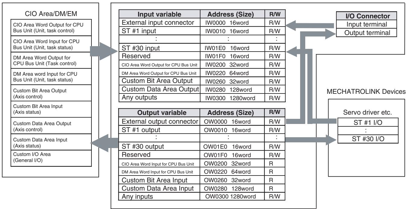
The R/W columns indicate the restriction on reading and writing from a program in the MC Unit. Of the output variables, the status output area cannot be written from the user program.
Writing data from a program in the MC Unit to the input variables linked to bit areas/data areas between the CPU Unit and the MC Unit enables the MC Unit to control the Unit, tasks, and axes.
Writing data from a program in the MC Unit to the output variables linked to the output signals of the MC Unit's I/O connector or MECHATROLINK-II output devices enables the MC Unit to control output signals.
4-6-2 List of Input Variables
Input Variables
| Input variable | Size | PC21 Bus Cyclic area | Classification | Access |
| IW0000 | 1 | --- | MC Unit external input terminal | R/W |
| IW0001-IW000F | 15 | --- | Reserved | R/W |
| IW0010-IW020F | 512 | --- | MECHATROLINK-II input Axis 1-32 | R/W |
| IW0210-IW02FF | 240 | --- | Reserved | R/W |
| IW0300-IW0302 | 3 | n - n+2 | Unit control bit | R/W |
| IW0303 | 1 | --- | Reserved | R/W |
| IW0304-IW0305 | 2 | --- | Zone control bits | R/W |
| IW0306-IW030F | 10 | --- | Reserved | R/W |
| IW0310 | 1 | m+20 | Unit control data | R/W |
| IW0311-IW031F | 15 | --- | Reserved | R/W |
| IW0320 | 1 | n+3 | Reserved | R/W |
| IW0321-IW032F | 15 | --- | Reserved | R/W |
| IW0330 | 1 | m+21 | Reserved | R/W |
| IW0331-IW033F | 15 | --- | Reserved | R/W |
| IW0340-IW0347 | 8 | n+4 - n+11 | Motion task 1-8 Control bit | R/W |
| IW0348-IW035F | 24 | --- | Reserved | R/W |
| IW0360-IW036F | 16 | m+22 - m+37 | Motion task 1-8 Control data | R/W |
| IW0370-IW043F | 208 | --- | Reserved | R/W |
| IW0440-IW045F | 32 | x - x+31 | Axis 1-32 Control bit | R/W |
| IW0460-IW047F | 32 | --- | Reserved | R/W |
| IW0480-IW049F | 32 | d - d+31 | Axis1-32 Control Data | R/W |
| IW04A0-IW04BF | 32 | --- | Axes 1 to 32 internal override | R/W |
| IW04C0-IW04DF | 32 | --- | Reserved | R/W |
| IW04E0-IW09FF | 1312 | --- | Reserved | R/W |
| IW0A00-IW0A07 | 8 | --- | 1. P0004 bit 13 = 0: Motion tasks 1 to 8 are acceleration/ deceleration time banks2. P0004 bit 13 = 1: Motion tasks 1 to 8 are acceleration time banks | R/W |
| IW0A08-IW0A0F | 8 | --- | P0004 bit 13 = 1: Motion tasks 1 to 8 are deceleration banks | R/W |
| IW0A10-IW0A3F | 56 | --- | Reserved | R/W |
| IW0A40-IW0AFF | 192 | --- | Reserved | R/W |
| IW0B00-IW0FFF | 1280 | Custom area | General I/O A-H | R/W |
The column "Access" indicate the restriction on both read/ write from motion programs. Of the output variables, the status output area cannot be written from the user program.
Writing data from motion programs to the input variables allocated to the PLC bit area enables the MC Unit to control the Unit, tasks, and axes.
Writing data from motion programs to the output variables allocated to the MECHATROLINK-II output devices and the MC Unit external output terminals enables the MC Unit to control the signal outputs.
Input variables indicate the data, which will be input to the MC Unit.
Details of Input Variables
| Variable Address R: ■ R/W: ■ | bit | Size | CPU Unit Word | Classification | Name | Specifications |
| IW0000 | 00 | 1 | --- | MC Unit External Input Terminals | External deceleration stop input | Reflects the input from the external deceleration stop input terminal. |
| 01 | Reserved | Reserved | ||||
| 02 | External general input 1 | Reflects the input from the external general input 1 terminal. | ||||
| 03 | External general input 2 | Reflects the input from the external general input 2 terminal. | ||||
| 04-15 | Reserved | Reserved | ||||
| IW0001 | 00-15 | 15 | --- | Reserved | Reserved | Reserved |
| IW000F | ||||||
| IW0010 | 00-15 | 16 | --- | MECHATROLINK-II Input Axis 1 | MECHATROLINK-II Input Axis1 CH1 | MECHATROLINK-II Input Axis1 CH1 |
| IW0011 | MECHATROLINK-II Input Axis1 CH2 | MECHATROLINK-II Input Axis1 CH2 | ||||
| IW0012 | MECHATROLINK-II Input Axis1 CH3 | MECHATROLINK-II Input Axis1 CH3 | ||||
| IW0013 | MECHATROLINK-II Input Axis1 CH4 | MECHATROLINK-II Input Axis1 CH4 | ||||
| IW0014 | MECHATROLINK-II Input Axis1 CH5 | MECHATROLINK-II Input Axis1 CH5 | ||||
| IW0015 | MECHATROLINK-II Input Axis1 CH6 | MECHATROLINK-II Input Axis1 CH6 | ||||
| IW0016 | MECHATROLINK-II Input Axis1 CH7 | MECHATROLINK-II Input Axis1 CH7 | ||||
| IW0017 | MECHATROLINK-II Input Axis1 CH8 | MECHATROLINK-II Input Axis1 CH8 | ||||
| IW0018 | MECHATROLINK-II Input Axis1 CH9 | MECHATROLINK-II Input Axis1 CH9 | ||||
| IW0019 | MECHATROLINK-II Input Axis1 CH10 | MECHATROLINK-II Input Axis1 CH10 | ||||
| IW001A | MECHATROLINK-II Input Axis1 CH11 | MECHATROLINK-II Input Axis1 CH11 | ||||
| IW001B | MECHATROLINK-II Input Axis1 CH12 | MECHATROLINK-II Input Axis1 CH12 | ||||
| IW001C | MECHATROLINK-II Input Axis1 CH13 | MECHATROLINK-II Input Axis1 CH13 | ||||
| IW001D | MECHATROLINK-II Input Axis1 CH14 | MECHATROLINK-II Input Axis1 CH14 | ||||
| IW001E | MECHATROLINK-II Input Axis1 CH15 | MECHATROLINK-II Input Axis1 CH15 | ||||
| IW001F | MECHATROLINK-II Input Axis1 CH16 | MECHATROLINK-II Input Axis1 CH16 | ||||
| IW0020 | 00-15 | 16 | --- | MECHATROLINK-II Input Axis 2 | Same as for MECHA-TROLINK-II Input Axis1 | Same as for MECHATROLINK-II Input Axis1 |
| IW002F | ||||||
| IW0030 | 00-15 | 16 | --- | MECHATROLINK-II Input Axis3 | Same as for MECHA-TROLINK-II Input Axis1 | Same as for MECHATROLINK-II Input Axis1 |
| IW003F | ||||||
| IW0040 | 00-15 | 16 | --- | MECHATROLINK-II Input Axis4 | Same as for MECHA-TROLINK-II Input Axis1 | Same as for MECHATROLINK-II Input Axis1 |
| IW004F | ||||||
| IW0050 | 00-15 | 16 | --- | MECHATROLINK-II Input Axis5 | Same as for MECHA-TROLINK-II Input Axis1 | Same as for MECHATROLINK-II Input Axis1 |
| IW005F | ||||||
| IW0060 | 00-15 | 16 | --- | MECHATROLINK-II Input Axis6 | Same as for MECHA-TROLINK-II Input Axis1 | Same as for MECHANOLINK-II Input Axis1 |
| IW006F | ||||||
| IW0070 | 00-15 | 16 | --- | MECHATROLINK-II Input Axis7 | Same as for MECHA-TROLINK-II Input Axis1 | Same as for MECHANOLINK-II Input Axis1 |
| IW007F | ||||||
| IW0080 | 00-15 | 16 | --- | MECHATROLINK-II Input Axis8 | Same as for MECHA-TROLINK-II Input Axis1 | Same as for MECHANOLINK-II Input Axis1 |
| IW008F | ||||||
| IW0090 | 00-15 | 16 | --- | MECHATROLINK-II Input Axis9 | Same as for MECHA-TROLINK-II Input Axis1 | Same as for MECHANOLINK-II Input Axis1 |
| IW009F | ||||||
| IW00A0 | 00-15 | 16 | --- | MECHATROLINK-II Input Axis10 | Same as for MECHA-TROLINK-II Input Axis1 | Same as for MECHANOLINK-II Input Axis1 |
| IW00AF | ||||||
| IW00B0 | 00-15 | 16 | --- | MECHANOLINK-II Input Axis11 | Same as for MECHA-TROLINK-II Input Axis1 | Same as for MECHANOLINK-II Input Axis1 |
| IW00BF | ||||||
| IW00C0 | 00-15 | 16 | --- | MECHANOLINK-II Input Axis12 | Same as for MECHA-TROLINK-II Input Axis1 | Same as for MECHANOLINK-II Input Axis1 |
| IW00CF | ||||||
| IW00D0 | 00-15 | 16 | --- | MECHANOLINK-II Input Axis13 | Same as for MECHA-TROLINK-II Input Axis1 | Same as for MECHANOLINK-II Input Axis1 |
| IW00DF | ||||||
| IW00E0 | 00-15 | 16 | --- | MECHATROLINK-II Input Axis14 | Same as for MECHA-TROLINK-II Input Axis1 | Same as for MECHATROLINK-II Input Axis1 |
| IW00EF | ||||||
| IW00F0 | 00-15 | 16 | --- | MECHATROLINK-II Input Axis15 | Same as for MECHA-TROLINK-II Input Axis1 | Same as for MECHATROLINK-II Input Axis1 |
| IW00FF | ||||||
| IW0100 | 00-15 | 16 | --- | MECHATROLINK-II Input Axis16 | Same as for MECHA-TROLINK-II Input Axis1 | Same as for MECHATROLINK-II Input Axis1 |
| IW010F | ||||||
| IW0110 | 00-15 | 16 | --- | MECHATROLINK-II Input Axis17 | Same as for MECHA-TROLINK-II Input Axis1 | Same as for MECHATROLINK-II Input Axis1 |
| IW011F | ||||||
| IW0120 | 00-15 | 16 | --- | MECHATROLINK-II Input Axis18 | Same as for MECHA-TROLINK-II Input Axis1 | Same as for MECHATROLINK-II Input Axis1 |
| IW012F | ||||||
| IW0130 | 00-15 | 16 | --- | MECHATROLINK-II Input Axis19 | Same as for MECHA-TROLINK-II Input Axis1 | Same as for MECHATROLINK-II Input Axis1 |
| IW013F | ||||||
| IW0140 | 00-15 | 16 | --- | MECHATROLINK-II Input Axis20 | Same as for MECHA-TROLINK-II Input Axis1 | Same as for MECHATROLINK-II Input Axis1 |
| IW014F | ||||||
| IW0150 | 00-15 | 16 | --- | MECHATROLINK-II Input Axis21 | Same as for MECHA-TROLINK-II Input Axis1 | Same as for MECHATROLINK-II Input Axis1 |
| IW015F | ||||||
| IW0160 | 00-15 | 16 | --- | MECHATROLINK-II Input Axis22 | Same as for MECHA-TROLINK-II Input Axis1 | Same as for MECHATROLINK-II Input Axis1 |
| IW016F | ||||||
| IW0170 | 00-15 | 16 | --- | MECHATROLINK-II Input Axis23 | Same as for MECHA-TROLINK-II Input Axis1 | Same as for MECHATROLINK-II Input Axis1 |
| IW017F | ||||||
| IW0180 | 00-15 | 16 | --- | MECHATROLINK-II Input Axis24 | Same as for MECHA-TROLINK-II Input Axis1 | Same as for MECHATROLINK-II Input Axis1 |
| IW018F | ||||||
| IW0190 | 00-15 | 16 | --- | MECHATROLINK-II Input Axis25 | Same as for MECHA-TROLINK-II Input Axis1 | Same as for MECHATROLINK-II Input Axis1 |
| IW019F | ||||||
| IW01A0 | 00-15 | 16 | --- | MECHATROLINK-II Input Axis26 | Same as for MECHA-TROLINK-II Input Axis1 | Same as for MECHATROLINK-II Input Axis1 |
| IW01AF | ||||||
| IW01B0 | 00-15 | 16 | --- | MECHATROLINK-II Input Axis27 | Same as for MECHA-TROLINK-II Input Axis1 | Same as for MECHATROLINK-II Input Axis1 |
| IW01BF | ||||||
| IW01C0 | 00-15 | 16 | --- | MECHATROLINK-II Input Axis28 | Same as for MECHA-TROLINK-II Input Axis1 | Same as for MECHATROLINK-II Input Axis1 |
| IW01CF | ||||||
| IW01D0 | 00-15 | 16 | --- | MECHATROLINK-II Input Axis29 | Same as for MECHA-TROLINK-II Input Axis1 | Same as for MECHATROLINK-II Input Axis1 |
| IW01DF | ||||||
| IW01E0 | 00-15 | 16 | --- | MECHATROLINK-II Input Axis30 | Same as for MECHA-TROLINK-II Input Axis1 | Same as for MECHATROLINK-II Input Axis1 |
| IW01EF | ||||||
| IW01F0 | 00-15 | 16 | --- | MECHATROLINK-II Input Axis31 | Same as for MECHA-TROLINK-II Input Axis1 | Same as for MECHATROLINK-II Input Axis1 |
| IW01FF | ||||||
| IW0200 | 00-15 | 16 | --- | MECHATROLINK-II Input Axis32 | Same as for MECHA-TROLINK-II Input Axis1 | Same as for MECHATROLINK-II Input Axis1 |
| IW020F | ||||||
| IW0210 | 00-15 | 240 | --- | Reserved | Reserved | Reserved |
| IW02FF | ||||||
| IW0300 | 00 | 1 | n+0 | Unit Control Bits | Unit alarm reset | 0: No1: Does not turn ON Unit alarm bit↑: Clears the alarm occurring on the unit level:No |
| 01 | System Parameter Save | 0: No1: No↑: Saves system parameters in MC Unit's Flash ROM/ servo parameters in Flash ROM and EEPROM of servo driver:No | ||||
| 02 | Position Data Save | 0: No1: No↑: Saves position data in Flash ROM↓: No | ||||
| 03 | Teaching Condition Setting | 0: No1: No↑: Sets teaching axis, reads teaching address↓: No | ||||
| 04 | Teaching Type | 0: Feedback present position1: Command present position↑: No↓: No | ||||
| 05 | Teaching Execution | 0: No1: No↑: Writes present positions in position data according to teaching type↓: No | ||||
| 06 | Servo parameter Save | 0: No1: No↑: Serves servo parameter to Flash ROM/ EEPROM in servo driver↓: No | ||||
| 07-11 | Reserved | Reserved | ||||
| 12-15 | Present Value MonitorSelect | Selects Data to be output to present value monitor0: Zero output1: FB position (selected coordinate system)2: FB position (machine coordinate system)3: Command position (selected coordinate system)4:Command position (machine coordinate system)5: FB speed 1 (speed command unit)6: FB speed 2 (by parameters)7: Command speed1 (Speed Command Unit)8: Command speed 2 (depends on parameters)9: Errors10: Torque command11-15: Reserved for system | ||||
| IW0301 | 00-15 | 1 | n+1 | Unit Control Bits | Teaching Axis Setting 1-16 | 0: No1: Specifies the axis as teaching object↑: No↓: No |
| IW0302 | 00-15 | 1 | n+2 | Teaching Axis Setting 17-32 | 0: No1: Specifies the axis as teaching object↑: No↓: No | |
| IW0303 | 00-15 | 1 | --- | --- | Reserved | Reserved |
| IW0304 | 00-15 | 1 | --- | --- | Zone Reservation Bits (No. 1 to 16) | Enables or disables zone bits No. 1 to 16.No. 1 corresponds to bit 0, and No. 16 corresponds to bit 150: Disable (Do not use)1: Enable (Use) |
| IW0305 | 00-15 | 1 | --- | --- | Zone Reservation Bits (No. 17 to 32) | Enables or disables zone bits No. 17 to 32.No. 17 corresponds to bit 0, and No. 32 corresponds to bit 150: Disable (Do not use)1: Enable (Use) |
| IW0306 | 00-15 | 13 | --- | Reserved | Reserved | Reserved |
| IW030F | ||||||
| IW0310 | 00-15 | 1 | m+20 | Unit Control Data | Teaching Address | Specifies the teaching start address0-10239 |
| IW0311 | 00-15 | 15 | --- | Reserved | Reserved | Reserved |
| IW031F | ||||||
| IW0320 | 00 | 1 | n+3 | Reserved | ||
| 01 | ||||||
| 02 | ||||||
| 03-15 | Reserved | Reserved | ||||
| IW0321 | 00-15 | 15 | --- | Reserved | Reserved | Reserved |
| IW032F | ||||||
| IW0330 | 00-15 | 1 | m+21 | Reserved | Reserved | Reserved |
| IW0331 | 00-15 | 15 | --- | Reserved | Reserved | Reserved |
| IW033F | ||||||
| IW0340 | 00 | 1 | n+4 | Motion Task 1Control | Motion Task Alarm Reset | 0: No1: Does not turn ON Motion taskalarm bit↑: Clears alarm occurring onmotion task level↓No |
| 01 | Motion Program Start | 0: No1: No↑: Starts motion program accord-ing to specified Start mode↓: No | ||||
| 02-03 | Start Mode | 0,3: Reads program No. and executes program from top1: Resumes program executionfrom middle of the block whoseNo. is being displayed as the running block No.2: Resumes program executionfrom the next block to the onewhose No. is being displayed asrunning block No. | ||||
| 04 | Deceleration Stop | 0: No1: Prohibits motion program start↑:Executes deceleration stopregardless of the block↓: No | ||||
| 05 | Block Stop | 0: No1: Prohibits motion program start↑:Executes deceleration stop atthe end of the block currentlybeing executed↓: No | ||||
| 06 | Single Block OperatingMode | 0: Turns OFF single-block operat-ing mode1: Turns On single-block operat-ing mode↑: No↓: No | ||||
| 07 | Task Override Enable | 0: Disables task override value(Override: 100%)1: Enables task override value↑: No↓: No | ||||
| 08-15 | Reserved | Reserved | ||||
| IW0341 | 00-15 | 7 | n+5 | Motion Task 2Control | Same as for Motion Task 1 | Same as for Motion Task 1 |
| IW0342 | n+6 | Motion Task 3Control | Same as for Motion Task 1 | Same as for Motion Task 1 | ||
| IW0343 | n+7 | Motion Task 4Control | Same as for Motion Task 1 | Same as for Motion Task 1 | ||
| IW0344 | n+8 | Motion Task 5Control | Same as for Motion Task 1 | Same as for Motion Task 1 | ||
| IW0345 | n+9 | Motion Task 6Control | Same as for Motion Task 1 | Same as for Motion Task 1 | ||
| IW0346 | n+10 | Motion Task 7Control | Same as for Motion Task 1 | Same as for Motion Task 1 | ||
| IW0347 | n+11 | Motion Task 8Control | Same as for Motion Task 1 | Same as for Motion Task 1 | ||
| IW0348 | 00-15 | 24 | --- | Reserved | Reserved | Reserved |
| IW035F | ||||||
| IW0360 | 00-15 | 1 | m+22 | Motion Task 1 Control Data | Motion Task 1 Program No. | Specifies program No. to be executed by Motion Task 0-499 |
| IW0361 | 00-15 | 1 | m+23 | Motion Task 1 Override | Sets override value to be used in motion program 0.00 to 327.67 [%] (unit: 0.01%) | |
| IW0362 | 00-15 | 2 | m+24 | Motion Task 2 Control Data | Same as for Motion Task 1 | Same as for Motion Task 1 |
| IW0363 | m+25 | |||||
| IW0364 | 00-15 | 2 | m+26 | Motion Task 3 Control Data | Same as for Motion Task 1 | Same as for Motion Task 1 |
| IW0365 | m+27 | |||||
| IW0366 | 00-15 | 2 | m+28 | Motion Task 4 Control Data | Same as for Motion Task 1 | Same as for Motion Task 1 |
| IW0367 | m+29 | |||||
| IW0368 | 00-15 | 2 | m+30 | Motion Task 5 Control Data | Same as for Motion Task 1 | Same as for Motion Task 1 |
| IW0369 | m+31 | |||||
| IW036A | 00-15 | 2 | m+32 | Motion Task 6 Control Data | Same as for Motion Task 1 | Same as for Motion Task 1 |
| IW036B | m+33 | |||||
| IW036C | 00-15 | 2 | m+34 | Motion Task 7 Control Data | Same as for Motion Task 1 | Same as for Motion Task 1 |
| IW036D | m+35 | |||||
| IW036E | 00-15 | 2 | m+36 | Motion Task 8 Control Data | Same as for Motion Task 1 | Same as for Motion Task 1 |
| IW036F | m+37 | |||||
| IW0370 | 00-15 | 208 | --- | Reserved | Reserved | Reserved |
| IW043F | ||||||
| IW0440 | 00 | 1 | x+0 | Axis 1 Control Bits | Axis Alarm Reset | 0: No1: Does not turn ON Axis alarm bit↑: Clears alarm occurring on axis level, and clears alarm at MECHATROLINK-II slaves↓: No |
| 01 | Deceleration Stop | 0: No1: Prohibits JOG, STEP, Origin search, and Machine origin return in manual mode↑: Deceleration stop (JOG, STEP, Origin search, and Machine origin return)↓: No | ||||
| 02 | Servo Lock | 0: No1: No↑: Starts servo-lock↓: No | ||||
| 03 | Servo Unlock | 0: No1: Prohibits servo-lock↑: Cancels servo-lock status↓: No | ||||
| 04 | JOG | 0: No1: Continues JOG operation↑: Starts JOG operation↓: Stops JOG operation | ||||
| 05 | STEP | 0: No1: Continues STEP operation↑: Starts STEP operation↓: Stops STEP operation | ||||
| 06 | Origin Search | 0: No1: Continues origin search↑: Starts origin search↓: Stops origin search | ||||
| 07 | Machine Origin Return | 0: No1: Continues Machine origin return (PTP)↑: Starts Machine origin return (PTP)↓: Stops Machine origin return (PTP) | ||||
| 08 | Error Counter Reset | 0: No1: No↑: Resets error counter*Command position = present position↓: No | ||||
| 09 | Forced Origin | 0: No1: No↑: Forces to set the present position to 0 to establish it as the origin (not during axis movement)↓: No | ||||
| 10 | ABS Origin Setting | 0: No1: No↑: Sets the ABS encoder origin↓: No | ||||
| 11 | Axis Override Enable | 0: Enables axis override value(Override: 100%)1: Enables axis override value↑: No↓: No | ||||
| IW0440 | 12 | 1 | x+0 | Axis 1 Control Bits | JOG/STEP Direction | 0: JOG and STEP operation in + direction 1: JOG and STEP operation in - direction ↑: No ↓: No |
| 13 | Axis Machine Lock | 0: Cancels axis machine lock mode 1: Axis machine lock mode ↑: No ↓: No | ||||
| 14 | Reserved | Reserved | ||||
| 15 | Manual/Automatic Mode | 0: Manual mode 1: Automatic mode ↑: Stops manual operation in progress with deceleration stop ↓: Stops automatic operation in progress with deceleration stop | ||||
| IW0441 | 00-15 | 31 | x+1 | Axis 2 Control Bits | Same as for Axis 1 | Same as for Axis 1 |
| IW0442 | x+2 | Axis 3 Control Bits | Same as for Axis 1 | Same as for Axis 1 | ||
| IW0443 | x+3 | Axis 4 Control Bits | Same as for Axis 1 | Same as for Axis 1 | ||
| IW0444 | x+4 | Axis 5 Control Bits | Same as for Axis 1 | Same as for Axis 1 | ||
| IW0445 | x+5 | Axis 6 Control Bits | Same as for Axis 1 | Same as for Axis 1 | ||
| IW0446 | x+6 | Axis 7 Control Bits | Same as for Axis 1 | Same as for Axis 1 | ||
| IW0447 | x+7 | Axis 8 Control Bits | Same as for Axis 1 | Same as for Axis 1 | ||
| IW0448 | x+8 | Axis 9 Control Bits | Same as for Axis 1 | Same as for Axis 1 | ||
| IW0449 | x+9 | Axis 10 ControlBits | Same as for Axis 1 | Same as for Axis 1 | ||
| IW044A | x+10 | Axis 11 ControlBits | Same as for Axis 1 | Same as for Axis 1 | ||
| IW044B | x+11 | Axis 12 ControlBits | Same as for Axis 1 | Same as for Axis 1 | ||
| IW044C | x+12 | Axis 13 ControlBits | Same as for Axis 1 | Same as for Axis 1 | ||
| IW044D | x+13 | Axis 14 ControlBits | Same as for Axis 1 | Same as for Axis 1 | ||
| IW044E | x+14 | Axis 15 ControlBits | Same as for Axis 1 | Same as for Axis 1 | ||
| IW044F | x+15 | Axis 16 ControlBits | Same as for Axis 1 | Same as for Axis 1 | ||
| IW0450 | x+16 | Axis 17 ControlBits | Same as for Axis 1 | Same as for Axis 1 | ||
| IW0451 | x+17 | Axis 18 ControlBits | Same as for Axis 1 | Same as for Axis 1 | ||
| IW0452 | x+18 | Axis 19 ControlBits | Same as for Axis 1 | Same as for Axis 1 | ||
| IW0453 | x+19 | Axis 20 ControlBits | Same as for Axis 1 | Same as for Axis 1 | ||
| IW0454 | x+20 | Axis 21 ControlBits | Same as for Axis 1 | Same as for Axis 1 | ||
| IW0455 | x+21 | Axis 22 ControlBits | Same as for Axis 1 | Same as for Axis 1 | ||
| IW0456 | x+22 | Axis 23 ControlBits | Same as for Axis 1 | Same as for Axis 1 | ||
| IW0457 | x+23 | Axis 24 ControlBits | Same as for Axis 1 | Same as for Axis 1 | ||
| IW0458 | x+24 | Axis 25 ControlBits | Same as for Axis 1 | Same as for Axis 1 | ||
| IW0459 | x+25 | Axis 26 ControlBits | Same as for Axis 1 | Same as for Axis 1 | ||
| IW045A | x+26 | Axis 27 ControlBits | Same as for Axis 1 | Same as for Axis 1 | ||
| IW045B | x+27 | Axis 28 ControlBits | Same as for Axis 1 | Same as for Axis 1 | ||
| IW045C | x+28 | Axis 29 ControlBits | Same as for Axis 1 | Same as for Axis 1 | ||
| IW045D | x+29 | Axis 30 ControlBits | Same as for Axis 1 | Same as for Axis 1 | ||
| IW045E | x+30 | Axis 31 ControlBits | Same as for Axis 1 | Same as for Axis 1 | ||
| IW045F | x+31 | Axis 32 ControlBits | Same as for Axis 1 | Same as for Axis 1 | ||
| IW0460 | 00-15 | 32 | --- | Reserved | Reserved | Reserved |
| IW047F | ||||||
| IW0480 | 00-15 | 1 | d+0 | Axis 1 ControlData | Axis 1 Override | Sets override value to be used foraxis0.00 to 327.67 [%] (unit: 0.01%) |
| IW0481 | 00-15 | 31 | d+1 | Axis 2 ControlData | Axis 2 Override | Same as for Axis 1 |
| IW0482 | d+2 | Axis 3 ControlData | Axis 3 Override | Same as for Axis 1 | ||
| IW0483 | d+3 | Axis 4 ControlData | Axis 4 Override | Same as for Axis 1 | ||
| IW0484 | d+4 | Axis 5 ControlData | Axis 5 Override | Same as for Axis 1 | ||
| IW0485 | d+5 | Axis 6 ControlData | Axis 6 Override | Same as for Axis 1 | ||
| IW0486 | d+6 | Axis 7 ControlData | Axis 7 Override | Same as for Axis 1 | ||
| IW0487 | d+7 | Axis 8 ControlData | Axis 8 Override | Same as for Axis 1 | ||
| IW0488 | d+8 | Axis 9 ControlData | Axis 9 Override | Same as for Axis 1 | ||
| IW0489 | d+9 | Axis 10 ControlData | Axis 10 Override | Same as for Axis 1 | ||
| IW048A | d+10 | Axis 11 ControlData | Axis 11 Override | Same as for Axis 1 | ||
| IW048B | d+11 | Axis 12 ControlData | Axis 12 Override | Same as for Axis 1 | ||
| IW048C | d+12 | Axis 13 ControlData | Axis 13 Override | Same as for Axis 1 | ||
| IW048D | d+13 | Axis 14 ControlData | Axis 14 Override | Same as for Axis 1 | ||
| IW048E | d+14 | Axis 15 ControlData | Axis 15 Override | Same as for Axis 1 | ||
| IW048F | d+15 | Axis 16 ControlData | Axis 16 Override | Same as for Axis 1 | ||
| IW0490 | d+16 | Axis 17 ControlData | Axis 17 Override | Same as for Axis 1 | ||
| IW0491 | d+17 | Axis 18 ControlData | Axis 18 Override | Same as for Axis 1 | ||
| IW0492 | d+18 | Axis 19 ControlData | Axis 19 Override | Same as for Axis 1 | ||
| IW0493 | d+19 | Axis 20 ControlData | Axis 20 Override | Same as for Axis 1 | ||
| IW0494 | d+20 | Axis 21 ControlData | Axis 21 Override | Same as for Axis 1 | ||
| IW0495 | d+21 | Axis 22 ControlData | Axis 22 Override | Same as for Axis 1 | ||
| IW0496 | d+22 | Axis 23 ControlData | Axis 23 Override | Same as for Axis 1 | ||
| IW0497 | d+23 | Axis 24 ControlData | Axis 24 Override | Same as for Axis 1 | ||
| IW0498 | d+24 | Axis 25 ControlData | Axis 25 Override | Same as for Axis 1 | ||
| IW0499 | d+25 | Axis 26 ControlData | Axis 26 Override | Same as for Axis 1 | ||
| IW049A | d+26 | Axis 27 ControlData | Axis 27 Override | Same as for Axis 1 | ||
| IW049B | d+27 | Axis 28 ControlData | Axis 28 Override | Same as for Axis 1 | ||
| IW049C | d+28 | Axis 29 ControlData | Axis 29 Override | Same as for Axis 1 | ||
| IW049D | d+29 | Axis 30 ControlData | Axis 30 Override | Same as for Axis 1 | ||
| IW049E | d+30 | Axis 31 ControlData | Axis 31 Override | Same as for Axis 1 | ||
| IW049F | d+31 | Axis 32 ControlData | Axis 32 Override | Same as for Axis 1 | ||
| IW04A0 | 00-15 | 1 | --- | Axis 1 ControlData | Axis 1 internal override | Used by adding it to the axis over-ride value. |
| IW04A1 | 00-15 | 31 | --- | Axis 2 ControlData | Axis 2 internal override | Same as for Axis 1 |
| IW04A2 | Axis 3 ControlData | Axis 3 internal override | Same as for Axis 1 | |||
| IW04A3 | Axis 4 ControlData | Axis 4 internal override | Same as for Axis 1 | |||
| IW04A4 | Axis 5 ControlData | Axis 5 internal override | Same as for Axis 1 | |||
| IW04A5 | Axis 6 ControlData | Axis 6 internal override | Same as for Axis 1 | |||
| IW04A6 | Axis 7 ControlData | Axis 7 internal override | Same as for Axis 1 | |||
| IW04A7 | Axis 8 ControlData | Axis 8 internal override | Same as for Axis 1 | |||
| IW04A8 | Axis 9 ControlData | Axis 9 internal override | Same as for Axis 1 | |||
| IW04A9 | Axis 10 ControlData | Axis 10 internal override | Same as for Axis 1 | |||
| IW04AA | Axis 11 ControlData | Axis 11 internal override | Same as for Axis 1 | |||
| IW04AB | Axis 12 ControlData | Axis 12 internal override | Same as for Axis 1 | |||
| IW04AC | Axis 13 ControlData | Axis 13 internal override | Same as for Axis 1 | |||
| IW04AD | Axis 14 ControlData | Axis 14 internal override | Same as for Axis 1 | |||
| IW04AE | Axis 15 ControlData | Axis 15 internal override | Same as for Axis 1 | |||
| IW04AF | Axis 16 ControlData | Axis 16 internal override | Same as for Axis 1 | |||
| IW04B0 | Axis 17 ControlData | Axis 17 internal override | Same as for Axis 1 | |||
| IW04B1 | Axis 18 ControlData | Axis 18 internal override | Same as for Axis 1 | |||
| IW04B2 | Axis 19 ControlData | Axis 19 internal override | Same as for Axis 1 | |||
| IW04B3 | Axis 20 ControlData | Axis 20 internal override | Same as for Axis 1 | |||
| IW04B4 | Axis 21 ControlData | Axis 21 internal override | Same as for Axis 1 | |||
| IW04B5 | Axis 22 ControlData | Axis 22 internal override | Same as for Axis 1 | |||
| IW04B6 | Axis 23 ControlData | Axis 23 internal override | Same as for Axis 1 | |||
| IW04B7 | Axis 24 ControlData | Axis 24 internal override | Same as for Axis 1P | |||
| IW04B8 | Axis 25 ControlData | Axis 25 internal override | Same as for Axis 1 | |||
| IW04B9 | Axis 26 ControlData | Axis 26 internal override | Same as for Axis 1 | |||
| IW04BA | Axis 27 ControlData | Axis 27 internal override | Same as for Axis 1 | |||
| IW04BB | Axis 28 ControlData | Axis 28 internal override | Same as for Axis 1 | |||
| IW04BC | Axis 29 ControlData | Axis 29 internal override | Same as for Axis 1 | |||
| IW04BD | Axis 30 ControlData | Axis 30 internal override | Same as for Axis 1 | |||
| IW04BE | Axis 31 ControlData | Axis 31 internal override | Same as for Axis 1 | |||
| IW04BF | 00-15 | 31 | --- | Axis 32 ControlData | Axis 32 internal override | Same as for Axis 1 |
| IW04C0 | 00-15 | 1 | --- | Axis 1 ControlData | Reserved | Reserved |
| IW04C1 | 00-15 | 31 | --- | Axis 2 ControlData | Reserved | Reserved |
| IW04C2 | Axis 3 ControlData | Reserved | Reserved | |||
| IW04C3 | Axis 4 ControlData | Reserved | Reserved | |||
| IW04C4 | Axis 5 ControlData | Reserved | Reserved | |||
| IW04C5 | Axis 6 ControlData | Reserved | Reserved | |||
| IW04C6 | Axis 7 ControlData | Reserved | Reserved | |||
| IW04C7 | Axis 8 ControlData | Reserved | Reserved | |||
| IW04C8 | Axis 9 ControlData | Reserved | Reserved | |||
| IW04C9 | Axis 10 ControlData | Reserved | Reserved | |||
| IW04CA | Axis 11 ControlData | Reserved | Reserved | |||
| IW04CB | Axis 12 ControlData | Reserved | Reserved | |||
| IW04CC | Axis 13 ControlData | Reserved | Reserved | |||
| IW04CD | Axis 14 ControlData | Reserved | Reserved | |||
| IW04CE | Axis 15 ControlData | Reserved | Reserved | |||
| IW04CF | Axis 16 ControlData | Reserved | Reserved | |||
| IW04D0 | Axis 17 ControlData | Reserved | Reserved | |||
| IW04D1 | Axis 18 ControlData | Reserved | Reserved | |||
| IW04D2 | Axis 19 ControlData | Reserved | Reserved | |||
| IW04D3 | Axis 20 ControlData | Reserved | Reserved | |||
| IW04D4 | Axis 21 ControlData | Reserved | Reserved | |||
| IW04D5 | Axis 22 ControlData | Reserved | Reserved | |||
| IW04D6 | Axis 23 ControlData | Reserved | Reserved | |||
| IW04D7 | Axis 24 ControlData | Reserved | Reserved | |||
| IW04D8 | Axis 25 ControlData | Reserved | Reserved | |||
| IW04D9 | Axis 26 ControlData | Reserved | Reserved | |||
| IW04DA | Axis 27 ControlData | Reserved | Reserved | |||
| IW04DB | Axis 28 ControlData | Reserved | Reserved | |||
| IW04DC | Axis 29 ControlData | Reserved | Reserved | |||
| IW04DD | 00-15 | 31 | --- | Axis 30 Control Data | Reserved | Reserved |
| IW04DE | Axis 31 Control Data | Reserved | Reserved | |||
| IW04DF | Axis 32 Control Data | Reserved | Reserved | |||
| IW04E0 | 00-15 | 1376 | --- | Reserved | Reserved | Reserved |
| IW09FF | ||||||
| IW0A00 | 00-15 | 1 | --- | Motion task 1 control data | 1. P0004 bit 13 = 0: Motion tasks 1 to 8 are acceleration/deceleration time banks 2. P0004 bit 13 = 1: Motion tasks 1 to 8 are acceleration time banks | 1. P0004 bit 13 = 0: Selects sys-tem parameter to use as interpolation feed acceleration/ deceleration time 1 to 10: P00M11 to P00M20 are used as interpolation feed acceleration/deceleration times Other: P00M02: Uses interpolation feed acceleration timeP00M03: Uses interpolation feed deceleration time 2. P0004 bit 13 = 1: Interpolation feed acceleration time setting 1 to 5: P00M11 to P00M15 are used as interpolation feed acceleration times Other: P00M02: Used as interpolation acceleration time |
| IW0A01 | 00-15 | 7 | --- | Motion task 2 control data | Same as for motion task 1 | Same as for motion task 1 |
| IW0A02 | Motion task 3 control data | Same as for motion task 1 | Same as for motion task 1 | |||
| IW0A03 | Motion task 4 control data | Same as for motion task 1 | Same as for motion task 1 | |||
| IW0A04 | Motion task 5 control data | Same as for motion task 1 | Same as for motion task 1 | |||
| IW0A05 | Motion task 6 control data | Same as for motion task 1 | Same as for motion task 1 | |||
| IW0A06 | Motion task 7 control data | Same as for motion task 1 | Same as for motion task 1 | |||
| IW0A07 | Motion task 8 control data | Same as for motion task 1 | Same as for motion task 1 | |||
| Variable Address R: R/W: | bit | Size | CPU Unit Word | Classification | Name | Specifications |
| IW0A08 | 00-15 | 1 | --- | Motion task 1 control data | P0004 bit 13 = 1:Motion tasks 1 to 8 deceleration time banks | P0004 bit 13 = 1: Interpolation feed deceleration time setting 1 to 5:P00M16 to P00M20 are used as interpolation feed deceleration times Other:P00M03: Used as interpolation feed deceleration time |
| IW0A09 | 7 | --- | Motion task 2 control data | Same as for motion task 1 | Same as for motion task 1 | |
| IW0A0A | Motion task 3 control data | Same as for motion task 1 | Same as for motion task 1 | |||
| IW0A0B | Motion task 4 control data | Same as for motion task 1 | Same as for motion task 1 | |||
| IW0A0C | Motion task 5 control data | Same as for motion task 1 | Same as for motion task 1 | |||
| IW0A0D | Motion task 6 control data | Same as for motion task 1 | Same as for motion task 1 | |||
| IW0A0E | Motion task 7 control data | Same as for motion task 1 | Same as for motion task 1 | |||
| IW0A0F | Motion task 8 control data | Same as for motion task 1 | Same as for motion task 1 | |||
| IW0A10 | 00-15 | 48 | --- | Reserved | Reserved | Reserved |
| IW0A3F | ||||||
| IW0A40 | 00-15 | 192 | --- | Reserved | Reserved | Reserved |
| IW0AFF | ||||||
| IW0B00 | 00-15 | 160 | a_A | General I/O A | General I/O A CH1-160 | Reflects data from General I/O A (CPU to MC Unit) |
| IW0B9F | ||||||
| IW0BA0 | 00-15 | 160 | a_B | General I/O B | General I/O B CH1-160 | Same as for General I/O A |
| IW0C3F | ||||||
| IW0C40 | 00-15 | 160 | a_C | General I/O C | General I/O C CH1-160 | Same as for General I/O A |
| IW0CDF | ||||||
| IW0CE0 | 00-15 | 160 | a_D | General I/O D | General I/O D CH1-160 | Same as for General I/O A |
| IW0D7F | ||||||
| IW0D80 | 00-15 | 160 | a_E | General I/O E | General I/O E CH1-160 | Same as for General I/O A |
| IW0E1F | ||||||
| IW0E20 | 00-15 | 160 | a_F | General I/O F | General I/O F CH1-160 | Same as for General I/O A |
| IW0EBF | ||||||
| IW0EC0 | 00-15 | 160 | a_G | General I/O G | General I/O G CH1-160 | Same as for General I/O A |
| IW0F5F | ||||||
| IW0F60 | 00-15 | 160 | a_H | General I/O H | General I/O H CH1-160 | Same as for General I/O A |
| IW0FFF |
4-6-3 List of Output Variables
Output variables
| Input variable | Size | PC21 Bus Cyclic area | Classification | Access |
| OW0000 | 1 | --- | MC Unit external output terminal | R/W |
| OW0001-OW000F | 15 | --- | Reserved | R/W |
| OW0010-OW020F | 512 | --- | MECHATROLINK-II output Axis 1-32 | R/W |
| OW0210-OW026F | 96 | --- | Slave Status Axis 1 to 32 | R |
| OW0270-OW02FF | 144 | --- | Reserved | R |
| OW0300-OW0303 | 4 | n+12 - n+15 | Unit status bits | R |
| OW0304-OW0305 | 2 | --- | Zone monitoring status bits | R |
| OW0306-OW030F | 10 | --- | Reserved | R |
| OW0310-OW0311 | 2 | m+38 - m+39 | Unit status data | R |
| OW0312-OW031F | 14 | --- | Reserved | R |
| OW0320 | 1 | n+3 | Reserved | R |
| OW0321-OW032F | 15 | --- | Reserved | R |
| OW0330-OW0331 | 1 | m+21 | Reserved | R |
| OW0332-OW033F | 15 | --- | Reserved | R |
| OW0340-OW0347 | 8 | n+17 - n+24 | Motion task 1-8 Status bits | R |
| OW0348-OW035F | 24 | --- | Reserved | R |
| OW0360-OW037F | 32 | m+42 - m+73 | Motion task 1-8 Status data | R |
| OW0380-OW043F | 192 | --- | Reserved | R |
| OW0440-OW045F | 32 | x+32 - x+63 | Axis 1-32 Status bits | R |
| OW0460-OW047F | 32 | --- | Reserved | R |
| OW0480-OW04DF | 96 | d+32 - d+127 | Axis1-32 Status data | R |
| OW04E0-OW0AFF | 1568 | --- | Reserved | R |
| OW0B00-OW0FFF | 1280 | Custom area | General I/O A-H | R/W |
The column "Access" in the above table indicate the restrictions for Reading and Writing from motion programs. It is prohibited to write from a user's program in the status output area.
Writing data from motion programs to the input variables allocated to the bit area in the PLC enables the MC Unit to control the Unit, tasks and axes.
Writing data from motion programs to the output variables allocated to MECHATROLINK-II output devices and the MC Unit external output terminals enables the MC Unit to control the signal outputs.
Output variables indicate the data that is output from the MC Unit.
Details of Output Variables
| Variable Address R:■ R/W:■ | bit | Size | CPU Unit Word | Classification | Name | Specifications |
| OW0000 | 00 | 1 | --- | MC Unit External Output Terminal | External General Output 1 | Sets output to external general output 1 terminal. |
| 01 | External General Output 2 | Sets output to external general output 2 terminal. | ||||
| 02-15 | Reserved | Reserved | ||||
| OW0001 | 00-15 | 15 | --- | Reserved | Reserved | Reserved |
| OW000F | ||||||
| OW0010 | 00-15 | 16 | --- | MECHATROLINK-IIOutput Axis 1 | MECHATROLINK-II Output Axis 1 CH1 | MECHATROLINK-II Output Axis 1 CH1 |
| OW0011 | MECHATROLINK-II Output Axis 1 CH2 | MECHATROLINK-II Output Axis 1 CH2 | ||||
| OW0012 | MECHATROLINK-II Output Axis 1 CH3 | MECHATROLINK-II Output Axis 1 CH3 | ||||
| OW0013 | MECHATROLINK-II Output Axis 1 CH4 | MECHATROLINK-II Output Axis 1 CH4 | ||||
| OW0014 | MECHATROLINK-II Output Axis 1 CH5 | MECHATROLINK-II Output Axis 1 CH5 | ||||
| OW0015 | MECHATROLINK-II Output Axis 1 CH6 | MECHATROLINK-II Output Axis 1 CH6 | ||||
| OW0016 | MECHATROLINK-II Output Axis 1 CH7 | MECHATROLINK-II Output Axis 1 CH7 | ||||
| OW0017 | MECHATROLINK-II Output Axis 1 CH8 | MECHATROLINK-II Output Axis 1 CH8 | ||||
| OW0018 | MECHATROLINK-II Output Axis 1 CH9 | MECHATROLINK-II Output Axis 1 CH9 | ||||
| OW0019 | MECHATROLINK-II Output Axis 1 CH10 | MECHATROLINK-II Output Axis 1 CH10 | ||||
| OW001A | MECHATROLINK-II Output Axis 1 CH11 | MECHATROLINK-II Output Axis 1 CH11 | ||||
| OW001B | MECHATROLINK-II Output Axis 1 CH12 | MECHATROLINK-II Output Axis 1 CH12 | ||||
| OW001C | MECHATROLINK-II Output Axis 1 CH13 | MECHATROLINK-II Output Axis 1 CH13 | ||||
| OW001D | MECHATROLINK-II Output Axis 1 CH14 | MECHATROLINK-II Output Axis 1 CH14 | ||||
| OW001E | MECHATROLINK-II Output Axis 1 CH15 | MECHATROLINK-II Output Axis 1 CH15 | ||||
| OW001F | MECHATROLINK-II Output Axis 1 CH16 | MECHATROLINK-II Output Axis 1 CH16 | ||||
| OW0020 | 00-15 | 16 | --- | MECHATROLINK-IIOutput Axis 1 CH2 | Same as for MECHA-TROLINK-II Output Axis 1 | Same as for MECHATROLINK-II Output Axis 1 |
| OW002F | ||||||
| OW0030 | 00-15 | 16 | --- | MECHATROLINK-IIOutput Axis 1 CH3 | Same as for MECHA-TROLINK-II Output Axis 1 | Same as for MECHATROLINK-II Output Axis 1 |
| OW003F | ||||||
| OW0040 | 00-15 | 16 | --- | MECHATROLINK-IIOutput Axis 1 CH4 | Same as for MECHA-TROLINK-II Output Axis 1 | Same as for MECHATROLINK-II Output Axis 1 |
| OW004F | ||||||
| OW0050 | 00-15 | 16 | --- | MECHATROLINK-IIOutput Axis 1 CH5 | Same as for MECHA-TROLINK-II Output Axis 1 | Same as for MECHATROLINK-II Output Axis 1 |
| OW005F | ||||||
| OW0060 | 00-15 | 16 | --- | MECHATROLINK-IIOutput Axis 1 CH6 | Same as for MECHA-TROLINK-II Output Axis 1 | Same as for MECHATROLINK-II Output Axis 1 |
| OW006F | ||||||
| OW0070 | 00-15 | 16 | --- | MECHATROLINK-IIOutput Axis 1 CH7 | Same as for MECHA-TROLINK-II Output Axis 1 | Same as for MECHATROLINK-II Output Axis 1 |
| OW007F | ||||||
| OW0080 | 00-15 | 16 | --- | MECHATROLINK-IIOutput Axis 1 CH8 | Same as for MECHA-TROLINK-II Output Axis 1 | Same as for MECHATROLINK-II Output Axis 1 |
| OW008F | ||||||
| OW0090 | 00-15 | 16 | --- | MECHATROLINK-IIOutput Axis 1 CH9 | Same as for MECHA-TROLINK-II Output Axis 1 | Same as for MECHATROLINK-II Output Axis 1 |
| OW009F | ||||||
| OW00A0 | 00-15 | 16 | --- | MECHATROLINK-IIOutput Axis 1 CH10 | Same as for MECHA-TROLINK-II Output Axis 1 | Same as for MECHATROLINK-II Output Axis 1 |
| OW00AF | ||||||
| OW00B0 | 00-15 | 16 | --- | MECHATROLINK-IIOutput Axis 1 CH11 | Same as for MECHA-TROLINK-II Output Axis 1 | Same as for MECHATROLINK-II Output Axis 1 |
| OW00BF | ||||||
| OW00C0 | 00-15 | 16 | --- | MECHATROLINK-IIOutput Axis 1CH12 | Same as for MECHA-TROLINK-II Output Axis 1 | Same as for MECHATROLINK-II Output Axis 1 |
| OW00CF | ||||||
| OW00D0 | 00-15 | 16 | --- | MECHATROLINK-IIOutput Axis 1CH13 | Same as for MECHA-TROLINK-II Output Axis 1 | Same as for MECHATROLINK-II Output Axis 1 |
| OW00DF | ||||||
| OW00E0 | 00-15 | 16 | --- | MECHATROLINK-IIOutput Axis 1CH14 | Same as for MECHA-TROLINK-II Output Axis 1 | Same as for MECHATROLINK-II Output Axis 1 |
| OW00EF | ||||||
| OW00F0 | 00-15 | 16 | --- | MECHATROLINK-IIOutput Axis 1CH15 | Same as for MECHA-TROLINK-II Output Axis 1 | Same as for MECHATROLINK-II Output Axis 1 |
| OW00FF | ||||||
| OW0100 | 00-15 | 16 | --- | MECHATROLINK-IIOutput Axis 1CH16 | Same as for MECHA-TROLINK-II Output Axis 1 | Same as for MECHATROLINK-II Output Axis 1 |
| OW010F | ||||||
| OW0110 | 00-15 | 16 | --- | MECHATROLINK-IIOutput Axis 1CH17 | Same as for MECHA-TROLINK-II Output Axis 1 | Same as for MECHATROLINK-II Output Axis 1 |
| OW011F | ||||||
| OW0120 | 00-15 | 16 | --- | MECHATROLINK-IIOutput Axis 1CH18 | Same as for MECHA-TROLINK-II Output Axis 1 | Same as for MECHATROLINK-II Output Axis 1 |
| OW012F | ||||||
| OW0130 | 00-15 | 16 | --- | MECHATROLINK-IIOutput Axis 1CH19 | Same as for MECHA-TROLINK-II Output Axis 1 | Same as for MECHATROLINK-II Output Axis 1 |
| OW013F | ||||||
| OW0140 | 00-15 | 16 | --- | MECHATROLINK-IIOutput Axis 1CH20 | Same as for MECHA-TROLINK-II Output Axis 1 | Same as for MECHATROLINK-II Output Axis 1 |
| OW014F | ||||||
| OW0150 | 00-15 | 16 | --- | MECHATROLINK-IIOutput Axis 1CH21 | Same as for MECHA-TROLINK-II Output Axis 1 | Same as for MECHATROLINK-II Output Axis 1 |
| OW015F | ||||||
| OW0160 | 00-15 | 16 | --- | MECHATROLINK-IIOutput Axis 1CH22 | Same as for MECHA-TROLINK-II Output Axis 1 | Same as for MECHATROLINK-II Output Axis 1 |
| OW016F | ||||||
| OW0170 | 00-15 | 16 | --- | MECHATROLINK-IIOutput Axis 1CH23 | Same as for MECHA-TROLINK-II Output Axis 1 | Same as for MECHATROLINK-II Output Axis 1 |
| OW017F | ||||||
| OW0180 | 00-15 | 16 | --- | MECHATROLINK-IIOutput Axis 1CH24 | Same as for MECHA-TROLINK-II Output Axis 1 | Same as for MECHATROLINK-II Output Axis 1 |
| OW018F | ||||||
| OW0190 | 00-15 | 16 | --- | MECHATROLINK-IIOutput Axis 1CH25 | Same as for MECHA-TROLINK-II Output Axis 1 | Same as for MECHATROLINK-II Output Axis 1 |
| OW019F | ||||||
| OW01A0 | 00-15 | 16 | --- | MECHATROLINK-IIOutput Axis 1CH26 | Same as for MECHA-TROLINK-II Output Axis 1 | Same as for MECHATROLINK-II Output Axis 1 |
| OW01AF | ||||||
| OW01B0 | 00-15 | 16 | --- | MECHATROLINK-IIOutput Axis 1CH27 | Same as for MECHA-TROLINK-II Output Axis 1 | Same as for MECHATROLINK-II Output Axis 1 |
| OW01BF | ||||||
| OW01C0 | 00-15 | 16 | --- | MECHATROLINK-IIOutput Axis 1CH28 | Same as for MECHA-TROLINK-II Output Axis 1 | Same as for MECHATROLINK-II Output Axis 1 |
| OW01CF | ||||||
| OW01D0 | 00-15 | 16 | --- | MECHATROLINK-IIOutput Axis 1CH29 | Same as for MECHA-TROLINK-II Output Axis 1 | Same as for MECHATROLINK-IIOutput Axis 1 |
| OW01DF | ||||||
| OW01E0 | 00-15 | 16 | --- | MECHATROLINK-IIOutput Axis 1CH30 | Same as for MECHA-TROLINK-II Output Axis 1 | Same as for MECHATROLINK-IIOutput Axis 1 |
| OW01EF | ||||||
| OW01F0 | 00-15 | 16 | --- | MECHATROLINK-IIOutput Axis 1CH31 | Same as for MECHA-TROLINK-II Output Axis 1 | Same as for MECHATROLINK-IIOutput Axis 1 |
| OW01FF | ||||||
| OW0200 | 00-15 | 16 | --- | MECHATROLINK-IIOutput Axis 1CH32 | Same as for MECHA-TROLINK-II Output Axis 1 | Same as for MECHATROLINK-IIOutput Axis 1 |
| OW020F | ||||||
| OW0210 | 00-15 | 16 | --- | Slave Status Axis 1 (Supported in Unit Ver. 3.0 or later) | Alarm/warning code | Stores the alarm or warning code when an alarm or warning has occurred in the MECHATROLINK-II Slave.This code is set to 0 when the Axis Alarm Reset for the axis is turned ON. |
| OW0211 | 00-15 | 16 | --- | Servo Status 1 | Stores the same value as Servo Status (SW021C). Refreshed each Unit cycle. | |
| OW0212 | 00-15 | 16 | --- | Servo Status 2 | Stores the same value as Servo Status (SW021D). Refreshed each Unit cycle. | |
| OW0213 | 00-15 | 16 | --- | Slave Status Axis 2 | Alarm/warning code | Same as for Axis 1 |
| OW0214 | 00-15 | 16 | --- | Servo Status 1 | Same as for Axis 1 | |
| OW0215 | 00-15 | 16 | --- | Servo Status 2 | Same as for Axis 1 | |
| OW0216 | 00-15 | 16 | --- | Slave Status Axis 3 | Alarm/warning code | Same as for Axis 1 |
| OW0217 | 00-15 | 16 | --- | Servo Status 1 | Same as for Axis 1 | |
| OW0218 | 00-15 | 16 | --- | Servo Status 2 | Same as for Axis 1 | |
| OW0219 | 00-15 | 16 | --- | Slave Status Axis 4 | Alarm/warning code | Same as for Axis 1 |
| OW021A | 00-15 | 16 | --- | Servo Status 1 | Same as for Axis 1 | |
| OW021B | 00-15 | 16 | --- | Servo Status 2 | Same as for Axis 1 | |
| OW021C | 00-15 | 16 | --- | Slave Status Axis 5 | Alarm/warning code | Same as for Axis 1 |
| OW021D | 00-15 | 16 | --- | Servo Status 1 | Same as for Axis 1 | |
| OW021E | 00-15 | 16 | --- | Servo Status 2 | Same as for Axis 1 | |
| OW021F | 00-15 | 16 | --- | Slave Status Axis 6 | Alarm/warning code | Same as for Axis 1 |
| OW0220 | 00-15 | 16 | --- | Servo Status 1 | Same as for Axis 1 | |
| OW0221 | 00-15 | 16 | --- | Servo Status 2 | Same as for Axis 1 | |
| OW0222 | 00-15 | 16 | --- | Slave Status Axis 7 | Alarm/warning code | Same as for Axis 1 |
| OW0223 | 00-15 | 16 | --- | Servo Status 1 | Same as for Axis 1 | |
| OW0224 | 00-15 | 16 | --- | Servo Status 2 | Same as for Axis 1 | |
| OW0225 | 00-15 | 16 | --- | Slave Status Axis 8 | Alarm/warning code | Same as for Axis 1 |
| OW0226 | 00-15 | 16 | --- | Servo Status 1 | Same as for Axis 1 | |
| OW0227 | 00-15 | 16 | --- | Servo Status 2 | Same as for Axis 1 | |
| OW0228 | 00-15 | 16 | --- | Slave Status Axis 9 | Alarm/warning code | Same as for Axis 1 |
| OW0229 | 00-15 | 16 | --- | Servo Status 1 | Same as for Axis 1 | |
| OW022A | 00-15 | 16 | --- | Servo Status 2 | Same as for Axis 1 | |
| OW022B | 00-15 | 16 | --- | Slave Status Axis 10 | Alarm/warning code | Same as for Axis 1 |
| OW022C | 00-15 | 16 | --- | Servo Status 1 | Same as for Axis 1 | |
| OW022D | 00-15 | 16 | --- | Servo Status 2 | Same as for Axis 1 | |
| OW022E | 00-15 | 16 | --- | Slave Status Axis 11 | Alarm/warning code | Same as for Axis 1 |
| OW022F | 00-15 | 16 | --- | Servo Status 1 | Same as for Axis 1 | |
| OW0230 | 00-15 | 16 | --- | Servo Status 2 | Same as for Axis 1 | |
| OW0231 | 00-15 | 16 | --- | Slave Status Axis 12 | Alarm/warning code | Same as for Axis 1 |
| OW0232 | 00-15 | 16 | --- | Servo Status 1 | Same as for Axis 1 | |
| OW0233 | 00-15 | 16 | --- | Servo Status 2 | Same as for Axis 1 | |
| OW0234 | 00-15 | 16 | --- | Slave Status Axis 13 | Alarm/warning code | Same as for Axis 1 |
| OW0235 | 00-15 | 16 | --- | Servo Status 1 | Same as for Axis 1 | |
| OW0236 | 00-15 | 16 | --- | Servo Status 2 | Same as for Axis 1 | |
| OW0237 | 00-15 | 16 | --- | Slave Status Axis 14 | Alarm/warning code | Same as for Axis 1 |
| OW0238 | 00-15 | 16 | --- | Servo Status 1 | Same as for Axis 1 | |
| OW0239 | 00-15 | 16 | --- | Servo Status 2 | Same as for Axis 1 | |
| OW023A | 00-15 | 16 | --- | Slave Status Axis 15 | Alarm/warning code | Same as for Axis 1 |
| OW023B | 00-15 | 16 | --- | Servo Status 1 | Same as for Axis 1 | |
| OW023C | 00-15 | 16 | --- | Servo Status 2 | Same as for Axis 1 | |
| OW023D | 00-15 | 16 | --- | Slave Status Axis 16 | Alarm/warning code | Same as for Axis 1 |
| OW023E | 00-15 | 16 | --- | Servo Status 1 | Same as for Axis 1 | |
| OW023F | 00-15 | 16 | --- | Servo Status 2 | Same as for Axis 1 | |
| OW0240 | 00-15 | 16 | --- | Slave Status Axis 17 | Alarm/warning code | Same as for Axis 1 |
| OW0241 | 00-15 | 16 | --- | Servo Status 1 | Same as for Axis 1 | |
| OW0242 | 00-15 | 16 | --- | Servo Status 2 | Same as for Axis 1 | |
| OW0243 | 00-15 | 16 | --- | Slave Status Axis 18 | Alarm/warning code | Same as for Axis 1 |
| OW0244 | 00-15 | 16 | --- | Servo Status 1 | Same as for Axis 1 | |
| OW0245 | 00-15 | 16 | --- | Servo Status 2 | Same as for Axis 1 | |
| OW0246 | 00-15 | 16 | --- | Slave Status Axis 19 | Alarm/warning code | Same as for Axis 1 |
| OW0247 | 00-15 | 16 | --- | Servo Status 1 | Same as for Axis 1 | |
| OW0248 | 00-15 | 16 | --- | Servo Status 2 | Same as for Axis 1 | |
| OW0249 | 00-15 | 16 | --- | Slave Status Axis 20 | Alarm/warning code | Same as for Axis 1 |
| OW024A | 00-15 | 16 | --- | Servo Status 1 | Same as for Axis 1 | |
| OW024B | 00-15 | 16 | --- | Servo Status 2 | Same as for Axis 1 | |
| OW024C | 00-15 | 16 | --- | Slave Status Axis 21 | Alarm/warning code | Same as for Axis 1 |
| OW024D | 00-15 | 16 | --- | Servo Status 1 | Same as for Axis 1 | |
| OW024E | 00-15 | 16 | --- | Servo Status 2 | Same as for Axis 1 | |
| OW024F | 00-15 | 16 | --- | Slave Status Axis 22 | Alarm/warning code | Same as for Axis 1 |
| OW0250 | 00-15 | 16 | --- | Servo Status 1 | Same as for Axis 1 | |
| OW0251 | 00-15 | 16 | --- | Servo Status 2 | Same as for Axis 1 | |
| OW0252 | 00-15 | 16 | --- | Slave Status Axis 23 | Alarm/warning code | Same as for Axis 1 |
| OW0253 | 00-15 | 16 | --- | Servo Status 1 | Same as for Axis 1 | |
| OW0254 | 00-15 | 16 | --- | Servo Status 2 | Same as for Axis 1 | |
| OW0255 | 00-15 | 16 | --- | Slave Status Axis 24 | Alarm/warning code | Same as for Axis 1 |
| OW0256 | 00-15 | 16 | --- | Servo Status 1 | Same as for Axis 1 | |
| OW0257 | 00-15 | 16 | --- | Servo Status 2 | Same as for Axis 1 | |
| OW0258 | 00-15 | 16 | --- | Slave Status Axis 25 | Alarm/warning code | Same as for Axis 1 |
| OW0259 | 00-15 | 16 | --- | Servo Status 1 | Same as for Axis 1 | |
| OW025A | 00-15 | 16 | --- | Servo Status 2 | Same as for Axis 1 | |
| OW025B | 00-15 | 16 | --- | Slave Status Axis 26 | Alarm/warning code | Same as for Axis 1 |
| OW025C | 00-15 | 16 | --- | Servo Status 1 | Same as for Axis 1 | |
| OW025D | 00-15 | 16 | --- | Servo Status 2 | Same as for Axis 1 | |
| OW025E | 00-15 | 16 | --- | Slave Status Axis 27 | Alarm/warning code | Same as for Axis 1 |
| OW025F | 00-15 | 16 | --- | Servo Status 1 | Same as for Axis 1 | |
| OW0260 | 00-15 | 16 | --- | Servo Status 2 | Same as for Axis 1 | |
| OW0261 | 00-15 | 16 | --- | Slave Status Axis 28 | Alarm/warning code | Same as for Axis 1 |
| OW0262 | 00-15 | 16 | --- | Servo Status 1 | Same as for Axis 1 | |
| OW0263 | 00-15 | 16 | --- | Servo Status 2 | Same as for Axis 1 | |
| OW0264 | 00-15 | 16 | --- | Slave Status Axis 29 | Alarm/warning code | Same as for Axis 1 |
| OW0265 | 00-15 | 16 | --- | Servo Status 1 | Same as for Axis 1 | |
| OW0266 | 00-15 | 16 | --- | Servo Status 2 | Same as for Axis 1 | |
| OW0267 | 00-15 | 16 | --- | Slave Status Axis 30 | Alarm/warning code | Same as for Axis 1 |
| OW0268 | 00-15 | 16 | --- | Servo Status 1 | Same as for Axis 1 | |
| OW0269 | 00-15 | 16 | --- | Servo Status 2 | Same as for Axis 1 | |
| OW026A | 00-15 | 16 | --- | Slave Status Axis 31 | Alarm/warning code | Same as for Axis 1 |
| OW026B | 00-15 | 16 | --- | Servo Status 1 | Same as for Axis 1 | |
| OW026C | 00-15 | 16 | --- | Servo Status 2 | Same as for Axis 1 | |
| OW026D | 00-15 | 16 | --- | Slave Status Axis 32 | Alarm/warning code | Same as for Axis 1 |
| OW026E | 00-15 | 16 | --- | Servo Status 1 | Same as for Axis 1 | |
| OW026F | 00-15 | 16 | --- | Servo Status 2 | Same as for Axis 1 | |
| OW0270 | 00-15 | 144 | --- | Reserved | Reserved | Reserved |
| OW02FF | ||||||
| OW0300 | 00 | 1 | n+12 | Alarm Identifica-tion | Alarm Occurring | 0: No alarm1: An alarm occurred on MC Unit (linked to ERC indicator). |
| 01 | Unit Alarm Occurring | 0: No alarm1: An alarm occurred on Unit level | ||||
| 02 | Reserved | |||||
| 03-10 | Motion Task Alarm Occur-ring 1-8 | 0: No alarm1: An alarm occurred on motion task level | ||||
| 11-15 | Reserved | Reserved | ||||
| OW0301 | 00-15 | 1 | n+13 | Axis Alarm Occurring 1-16 | 0: No alarm1: An alarm occurred on axis | |
| OW0302 | 00-15 | 1 | n+14 | Axis Alarm Occurring 17-32 | 0: No alarm1: An alarm occurred on axis | |
| OW0303 | 00 | 1 | n+15 | Unit Status | Unit Ready | 0: Unit is not ready to receive commands1: Unit is ready to receive commands |
| 01 | Unit Alarm | 0: No alarm1: An alarm occurred on Unit level | ||||
| 02 | F-ROM Save Completed | 0: Saving neither parameters nor position data has been completed1: Saving either parameters or position data has been completed (error completion included) | ||||
| 03 | Teaching Warning | 0: Teaching condition setting and execution completed normally1: Condition error, Command disabled, No origin, or address over flow | ||||
| 04 | Teaching Condition Setting Completed | 0: When Teaching condition setting is OFF1: Teaching condition setting completed (error completion included) | ||||
| 05 | Teaching Execution Com- pleted | 0: When teaching execution is OFF1: Teaching execution completed (error completed included) | ||||
| 06 | MECHATROLINK-II Device Search Execution | 0: Normal status1: Started MECHATROLINK-II device search | ||||
| 07 | External Forced Stop Request | 0: No external forced stop request from FINS, etc. (not from input variable)1: External forced stop requested from FINS, etc. (not from input variable) | ||||
| 08 | External Forced Stop Status | 0: No forced stop request, or pro- cessing for stopping1: Stopped by forced stop request | ||||
| 09 | Operating Mode (Supported in Unit Ver. 3.0 or later) | Gives the current MC Unit operat- ing mode.0: RUN or CPU mode1: Tool mode | ||||
| 10 | Reserved | Reserved | ||||
| 11 | Reserved | Reserved | ||||
| 12-15 | Present Value Monitor Sta- tus | Displays the present value moni- toring output status0: Zero output1: FB position (selected coordi- nate system)2: FB position (machine coordi- nate system)3: Command position (selected coordinate system)4: Command position (machine coordinate system)5: FB speed 1 (speed command unit)6: FB speed 2 (depends on parameters)7: Command speed 1 (speed command unit)8: Command speed 2 (depends on parameters)9: Error10: Torque command11-15: Reserved for system | ||||
| OW0304 | 00-15 | 1 | --- | --- | Zone Monitoring Status Bits (No. 1 to 16) (Supported for unit version 3.0 and later.) | Outputs whether zone bits No. 1 to 16 can be used. No. 1 corresponds to bit 0, and No. 16 corresponds to bit 15. 0: The upper or lower limit setting for the zone is incorrect, or the Zone Enable Bit is OFF (disabled). 1: The upper and lower limit settings for the zone are correct and the Zone Enable Bit is ON (enabled). |
| OW0305 | 00-15 | 1 | --- | --- | Zone Monitoring Status Bits (No. 17 to 32) (Supported for unit version 3.0 and later.) | Outputs whether zone bits No. 17 to 32 can be used. No. 17 corresponds to bit 0, and No. 32 corresponds to bit 15. 0: The upper or lower limit setting for the zone is incorrect, or the Zone Enable Bit is OFF (disabled). 1: The upper and lower limit settings for the zone are correct and the Zone Enable Bit is ON (enabled). |
| OW0306 | 00-15 | 12 | --- | Reserved | Reserved | Reserved |
| OW030F | ||||||
| OW0310 | 00-15 | 1 | m+38 | Unit Status Data | Unit Alarm Code | Outputs the alarm code for alarm occurring on Unit level |
| OW0311 | 00-15 | 1 | m+39 | Teaching Address Monitoring | Outputs an address currently being the teaching object | |
| OW0312 | 00-15 | 14 | --- | Reserved | Reserved | Reserved |
| OW031F | ||||||
| OW0320 | 00 | 1 | n+16 | Reserved | ||
| 01 | ||||||
| 02-15 | Reserved | Reserved | ||||
| OW0321 | 00-15 | 15 | --- | Reserved | Reserved | Reserved |
| OW032F | ||||||
| OW0330 | 00-15 | 1 | m+40 | Reserved | ||
| OW0331 | 00-15 | 1 | m+41 | |||
| OW0332 | 00-15 | 14 | --- | Reserved | Reserved | Reserved |
| OW033F | ||||||
| OW0340 | 00 | 1 | n+17 | Motion Task 1 Sta-tus | Motion Task Alarm | 0: No alarm occurring on motion task level1: An alarm occurred on motion task level |
| 01 | Motion Program Operating | 0: Motion task is not executing motion program1: Motion task is in program operation (Turned OFF after completion of deceleration/block stop) | ||||
| 02 | Motion Program Operation Completed | 0: When program operation is started1: Executed END command | ||||
| 03 | In Block Stop | 0: Block not stopped1: Block stopped | ||||
| 04 | Speed Clamp Warning | 0: Speed not clamped1: Speed clamped due to maximum speed limit | ||||
| 05 | Start Warning | 0: Motion program operation started1: Motion program operation could not be started (Axis declaration, Axis mode) | ||||
| 06 | Start Bit (Supported in Unit Ver. 3.0 or later) | 0: Motion Program Operating Bit is OFF (0/disabled)1: Motion Program Operating Bit is ON (1/enabled) | ||||
| 07-15 | Reserved | Reserved | ||||
| OW0341 | 00-15 | 7 | n+18 | Motion Task 2 Sta-tus | Same as for Motion Task 1 Status | Same as for Motion Task 1 Status |
| OW0342 | n+19 | Motion Task 3 Sta-tus | Same as for Motion Task 1 Status | Same as for Motion Task 1 Status | ||
| OW0343 | n+20 | Motion Task 4 Sta-tus | Same as for Motion Task 1 Status | Same as for Motion Task 1 Status | ||
| OW0344 | n+21 | Motion Task 5 Sta-tus | Same as for Motion Task 1 Status | Same as for Motion Task 1 Status | ||
| OW0345 | n+22 | Motion Task 6 Sta-tus | Same as for Motion Task 1 Status | Same as for Motion Task 1 Status | ||
| OW0346 | n+23 | Motion Task 7 Sta-tus | Same as for Motion Task 1 Status | Same as for Motion Task 1 Status | ||
| OW0347 | n+24 | Motion Task 8 Sta-tus | Same as for Motion Task 1 Status | Same as for Motion Task 1 Status | ||
| OW0348 | 00-15 | 24 | --- | Reserved | Reserved | Reserved |
| OW035F | ||||||
| OW0360 | 00-15 | 1 | m+42 | Motion Task 1 Sta-tus Data | Motion Task Alarm Code | Outputs the alarm code for alarm occurring on motion task level |
| OW0361 | 00-15 | 1 | m+43 | Executing Motion Program No. | The program No. of the program currently being executed by a motion task, or temporarily stopped is output | |
| OW0362 | 00-15 | 1 | m+44 | Executing Motion Block No. (Single execution command) | The block No. of the single execution command currently being executed by a motion task, or temporarily stopped, is out-put.During execution of parallel branching, the block No. of the leftmost block is output | |
| OW0363 | 00-15 | 1 | m+45 | Executing Motion Block No. (Multiple execution command) | The block No. of the multiple execution command currently being executed by a motion task, or temporarily stopped is output.During execution of parallel branching, the block No. of the leftmost block is output. | |
| OW0364 | 00-15 | 28 | m+46 | Motion task 2 Sta-tus Data | Same as for Motion Task 1 Status Data | Same as for Motion Task 1 Status Data |
| OW0365 | m+47 | |||||
| OW0366 | m+48 | |||||
| OW0367 | m+49 | |||||
| OW0368 | m+50 | Motion task 3 Sta-tus Data | Same as for Motion Task 1 Status Data | Same as for Motion Task 1 Status Data | ||
| OW0369 | m+51 | |||||
| OW036A | m+52 | |||||
| OW036B | m+53 | |||||
| OW036C | m+54 | Motion task 4 Sta-tus Data | Same as for Motion Task 1 Status Data | Same as for Motion Task 1 Status Data | ||
| OW036D | m+55 | |||||
| OW036E | m+56 | |||||
| OW036F | m+57 | |||||
| OW0370 | m+58 | Motion task 5 Sta-tus Data | Same as for Motion Task 1 Status Data | Same as for Motion Task 1 Status Data | ||
| OW0371 | m+59 | |||||
| OW0372 | m+60 | |||||
| OW0373 | m+61 | |||||
| OW0374 | m+62 | Motion task 6 Sta-tus Data | Same as for Motion Task 1 Status Data | Same as for Motion Task 1 Status Data | ||
| OW0375 | m+63 | |||||
| OW0376 | m+64 | |||||
| OW0377 | m+65 | |||||
| OW0378 | m+66 | Motion task 7 Sta-tus Data | Same as for Motion Task 1 Status Data | Same as for Motion Task 1 Status Data | ||
| OW0379 | m+67 | |||||
| OW037A | m+68 | |||||
| OW037B | m+69 | |||||
| OW037C | m+70 | Motion task 8 Sta-tus Data | Same as for Motion Task 1 Status Data | Same as for Motion Task 1 Status Data | ||
| OW037D | m+71 | |||||
| OW037E | m+72 | |||||
| OW037F | m+73 | |||||
| OW0380 | 00-15 | 192 | --- | Reserved | Reserved | Reserved |
| OW043F | ||||||
| OW0440 | 00 | 1 | x+32 | Axis 1 Status Bits | Axis Alarm | 0: No alarm on axis or MECHA-TROLINK-II slave1: An alarm occurred on axis or MECHATROLINK-II slave |
| 01 | Machine Origin | 0: Machine coordinate system FB position is outside of origin in-position range1: Machine coordinate system FB position is within origin position in-position range | ||||
| 02 | Busy | 0: None of the functions listed below is being executed1: One of the functions listed below is being executed or command is ON(JOG, STEP, Origin search, Machine origin return, Error counter reset, Forced origin, or ABS origin setting) | ||||
| 03 | In Servo Lock | 0: In Servo-lock1: In Servo-unlock | ||||
| 04 | No Origin | 0: Origin on machine coordinate system is established1: Origin on machine coordinate system is not established | ||||
| 05 | Axis Operating | 0: No axis operating command1: Axis operating command being output | ||||
| 06 | Positioning Completed | 0: Command value being output or outside of in-position range1: Command value not being output and within in-position range | ||||
| 07 | Positioning Completed (No.2) | 0: Command value being output or outside of NO.2 in-position range1: Command value not being output and within No.2 in-position range | ||||
| 08 | Error Counter Warning | 0: Error amount is within the range of error counter warning value1: Error amount is outside (exceeded) of the range of error counter warning value | ||||
| 09 | Axis Machine Lock Status | 0: Cancels axis machine lock mode1: In axis machine lock mode | ||||
| 10 | Counter Latch Completed | 0: Counter latch not completed1: Counter latch completed | ||||
| 11 | MECHATROLINK Warning | 0: No warning detected on MECHATROLINK-II device1: Warning detected on MECHA-TROLINK-II device | ||||
| 12 | Main power ON(Supported in Unit Ver. 3.0 or later) | 0: Servo Driver 's main power OFF1: Servo Driver 's main power ON | ||||
| 13 | Command Disabled/Enabled | 0: Not allocated or implemented1: Allocated and implemented (always 1 for virtual axis) | ||||
| 14 | Axis Not Used/Used | 0: Axis not used1: Axis in use (Manual: During JOG execution, etc., Automatic: Axis declared in a running program) | ||||
| 15 | In Manual/Automatic Mode | 0: In manual mode1: In automatic mode | ||||
| OW0441 | 00-15 | 31 | x+33 | Axis 2 Status Bits | Same as for Axis 1 StatusBits | Same as for Axis 1 Status Bits |
| OW0442 | x+34 | Axis 3 Status Bits | Same as for Axis 1 StatusBits | Same as for Axis 1 Status Bits | ||
| OW0443 | x+35 | Axis 4 Status Bits | Same as for Axis 1 StatusBits | Same as for Axis 1 Status Bits | ||
| OW0444 | x+36 | Axis 5 Status Bits | Same as for Axis 1 StatusBits | Same as for Axis 1 Status Bits | ||
| OW0445 | x+37 | Axis 6 Status Bits | Same as for Axis 1 StatusBits | Same as for Axis 1 Status Bits | ||
| OW0446 | x+38 | Axis 7 Status Bits | Same as for Axis 1 StatusBits | Same as for Axis 1 Status Bits | ||
| OW0447 | x+39 | Axis 8 Status Bits | Same as for Axis 1 StatusBits | Same as for Axis 1 Status Bits | ||
| OW0448 | x+40 | Axis 9 Status Bits | Same as for Axis 1 StatusBits | Same as for Axis 1 Status Bits | ||
| OW0449 | x+41 | Axis 10 Status Bits | Same as for Axis 1 StatusBits | Same as for Axis 1 Status Bits | ||
| OW044A | x+42 | Axis 11 Status Bits | Same as for Axis 1 StatusBits | Same as for Axis 1 Status Bits | ||
| OW044B | x+43 | Axis 12 Status Bits | Same as for Axis 1 StatusBits | Same as for Axis 1 Status Bits | ||
| OW044C | x+44 | Axis 13 Status Bits | Same as for Axis 1 StatusBits | Same as for Axis 1 Status Bits | ||
| OW044D | x+45 | Axis 14 Status Bits | Same as for Axis 1 StatusBits | Same as for Axis 1 Status Bits | ||
| OW044E | x+46 | Axis 15 Status Bits | Same as for Axis 1 StatusBits | Same as for Axis 1 Status Bits | ||
| OW044F | x+47 | Axis 16 Status Bits | Same as for Axis 1 StatusBits | Same as for Axis 1 Status Bits | ||
| OW0450 | x+48 | Axis 17 Status Bits | Same as for Axis 1 StatusBits | Same as for Axis 1 Status Bits | ||
| OW0451 | x+49 | Axis 18 Status Bits | Same as for Axis 1 StatusBits | Same as for Axis 1 Status Bits | ||
| OW0452 | x+50 | Axis 19 Status Bits | Same as for Axis 1 StatusBits | Same as for Axis 1 Status Bits | ||
| OW0453 | x+51 | Axis 20 Status Bits | Same as for Axis 1 StatusBits | Same as for Axis 1 Status Bits | ||
| OW0454 | x+52 | Axis 21 Status Bits | Same as for Axis 1 StatusBits | Same as for Axis 1 Status Bits | ||
| OW0455 | x+53 | Axis 22 Status Bits | Same as for Axis 1 StatusBits | Same as for Axis 1 Status Bits | ||
| OW0456 | x+54 | Axis 23 Status Bits | Same as for Axis 1 StatusBits | Same as for Axis 1 Status Bits | ||
| OW0457 | x+55 | Axis 24 Status Bits | Same as for Axis 1 StatusBits | Same as for Axis 1 Status Bits | ||
| OW0458 | x+56 | Axis 25 Status Bits | Same as for Axis 1 StatusBits | Same as for Axis 1 Status Bits | ||
| OW0459 | x+57 | Axis 26 Status Bits | Same as for Axis 1 StatusBits | Same as for Axis 1 Status Bits | ||
| OW045A | x+58 | Axis 27 Status Bits | Same as for Axis 1 StatusBits | Same as for Axis 1 Status Bits | ||
| OW045B | x+59 | Axis 28 Status Bits | Same as for Axis 1 StatusBits | Same as for Axis 1 Status Bits | ||
| OW045C | x+60 | Axis 29 Status Bits | Same as for Axis 1 StatusBits | Same as for Axis 1 Status Bits | ||
| OW045D | x+61 | Axis 30 Status Bits | Same as for Axis 1 StatusBits | Same as for Axis 1 Status Bits | ||
| OW045E | x+62 | Axis 31 Status Bits | Same as for Axis 1 StatusBits | Same as for Axis 1 Status Bits | ||
| OW045F | x+63 | Axis 32 Status Bits | Same as for Axis 1 StatusBits | Same as for Axis 1 Status Bits | ||
| OW0460 | 00-15 | 32 | --- | Reserved | Reserved | Reserved |
| OW047F | ||||||
| OW0480 | 00-15 | 1 | d+32 | Axis 1 Status Data | Axis Alarm Code | Output the alarm code for alarm occurring on axis or MECHA-TROLINK-II slave |
| OW0481 | 00-15 | 2 | d+33 | Present Value Monitor | Selected from the following 8 items for output1: FB position (selected coordinate system)2: FB position (machine coordinate system)3: Command position (selected coordinate system)4: Command position (machine coordinate system)5: FB speed6: Command speed7: Error8: Torque Command | |
| OW0482 | d+34 | |||||
| OW0483 | 00-15 | 93 | d+35 | Axis 2 Status Data | Same as for Axis 1 Status Data | Same as for Axis 1 Status Data |
| OW0484 | d+36 | |||||
| OW0485 | d+37 | |||||
| OW0486 | d+38 | Axis 3 Status Data | Same as for Axis 1 Status Data | Same as for Axis 1 Status Data | ||
| OW0487 | d+39 | |||||
| OW0488 | d+40 | |||||
| OW0489 | d+41 | Axis 4 Status Data | Same as for Axis 1 Status Data | Same as for Axis 1 Status Data | ||
| OW048A | d+42 | |||||
| OW048B | d+43 | |||||
| OW048C | d+44 | Axis 5 Status Data | Same as for Axis 1 Status Data | Same as for Axis 1 Status Data | ||
| OW048D | d+45 | |||||
| OW048E | d+46 | |||||
| OW048F | d+47 | Axis 6 Status Data | Same as for Axis 1 Status Data | Same as for Axis 1 Status Data | ||
| OW0490 | d+48 | |||||
| OW0491 | d+49 | |||||
| OW0492 | d+50 | Axis 7 Status Data | Same as for Axis 1 Status Data | Same as for Axis 1 Status Data | ||
| OW0493 | d+51 | |||||
| OW0494 | d+52 | |||||
| OW0495 | d+53 | Axis 8 Status Data | Same as for Axis 1 Status Data | Same as for Axis 1 Status Data | ||
| OW0496 | d+54 | |||||
| OW0497 | d+55 | |||||
| OW0498 | d+56 | Axis 9 Status Data | Same as for Axis 1 Status Data | Same as for Axis 1 Status Data | ||
| OW0499 | d+57 | |||||
| OW049A | d+58 | |||||
| OW049B | d+59 | Axis 10 Status Data | Same as for Axis 1 Status Data | Same as for Axis 1 Status Data | ||
| OW049C | d+60 | |||||
| OW049D | d+61 | |||||
| OW049E | d+62 | Axis 11 Status Data | Same as for Axis 1 Status Data | Same as for Axis 1 Status Data | ||
| OW049F | d+63 | |||||
| OW04A0 | d+64 | |||||
| OW04A1 | d+65 | Axis 12 Status Data | Same as for Axis 1 Status Data | Same as for Axis 1 Status Data | ||
| OW04A2 | d+66 | |||||
| OW04A3 | d+67 | |||||
| OW04A4 | d+68 | Axis 13 Status Data | Same as for Axis 1 Status Data | Same as for Axis 1 Status Data | ||
| OW04A5 | d+69 | |||||
| OW04A6 | d+70 | |||||
| OW04A7 | 00-15 | 93 | d+71 | Axis 14 StatusData | Same as for Axis 1 Status Data | Same as for Axis 1 Status Data |
| OW04A8 | d+72 | |||||
| OW04A9 | d+73 | |||||
| OW04AA | d+74 | Axis 15 StatusData | Same as for Axis 1 Status Data | Same as for Axis 1 Status Data | ||
| OW04AB | d+75 | |||||
| OW04AC | d+76 | |||||
| OW04AD | d+77 | Axis 16 StatusData | Same as for Axis 1 Status Data | Same as for Axis 1 Status Data | ||
| OW04AE | d+78 | |||||
| OW04AF | d+79 | |||||
| OW04B0 | d+80 | Axis 17 StatusData | Same as for Axis 1 Status Data | Same as for Axis 1 Status Data | ||
| OW04B1 | d+81 | |||||
| OW04B2 | d+82 | |||||
| OW04B3 | d+83 | Axis 18 StatusData | Same as for Axis 1 Status Data | Same as for Axis 1 Status Data | ||
| OW04B4 | d+84 | |||||
| OW04B5 | d+85 | |||||
| OW04B6 | d+86 | Axis 19 StatusData | Same as for Axis 1 Status Data | Same as for Axis 1 Status Data | ||
| OW04B7 | d+87 | |||||
| OW04B8 | d+88 | |||||
| OW04B9 | d+89 | Axis 20 StatusData | Same as for Axis 1 Status Data | Same as for Axis 1 Status Data | ||
| OW04BA | d+90 | |||||
| OW04BB | d+91 | |||||
| OW04BC | d+92 | Axis 21 StatusData | Same as for Axis 1 Status Data | Same as for Axis 1 Status Data | ||
| OW04BD | d+93 | |||||
| OW04BE | d+94 | |||||
| OW04BF | d+95 | Axis 22 StatusData | Same as for Axis 1 Status Data | Same as for Axis 1 Status Data | ||
| OW04C0 | d+96 | |||||
| OW04C1 | d+97 | |||||
| OW04C2 | d+98 | Axis 23 StatusData | Same as for Axis 1 Status Data | Same as for Axis 1 Status Data | ||
| OW04C3 | d+99 | |||||
| OW04C4 | d+100 | |||||
| OW04C5 | d+101 | Axis 24 StatusData | Same as for Axis 1 Status Data | Same as for Axis 1 Status Data | ||
| OW04C6 | d+102 | |||||
| OW04C7 | d+103 | |||||
| OW04C8 | d+104 | Axis 25 StatusData | Same as for Axis 1 Status Data | Same as for Axis 1 Status Data | ||
| OW04C9 | d+105 | |||||
| OW04CA | d+106 | |||||
| OW04CB | d+107 | Axis 26 StatusData | Same as for Axis 1 Status Data | Same as for Axis 1 Status Data | ||
| OW04CC | d+108 | |||||
| OW04CD | d+109 | |||||
| OW04CE | d+110 | Axis 27 StatusData | Same as for Axis 1 Status Data | Same as for Axis 1 Status Data | ||
| OW04CF | d+111 | |||||
| OW04D0 | d+112 | |||||
| OW04D1 | d+113 | Axis 28 StatusData | Same as for Axis 1 Status Data | Same as for Axis 1 Status Data | ||
| OW04D2 | d+114 | |||||
| OW04D3 | d+115 | |||||
| OW04D4 | d+116 | Axis 29 StatusData | Same as for Axis 1 Status Data | Same as for Axis 1 Status Data | ||
| OW04D5 | d+117 | |||||
| OW04D6 | d+118 | |||||
| OW04D7 | d+119 | Axis 30 StatusData | Same as for Axis 1 Status Data | Same as for Axis 1 Status Data | ||
| OW04D8 | d+120 | |||||
| OW04D9 | d+121 | |||||
| Variable Address R: ▪ R/W: ▪ | bit | Size | CPU Unit Word | Classification | Name | Specifications |
| OW04DA | 00-15 | 93 | d+122 | Axis 31 Status Data | Same as for Axis 1 Status Data | Same as for Axis 1 Status Data |
| OW04DB | d+123 | |||||
| OW04DC | d+124 | |||||
| OW04DD | d+125 | Axis 32 Status Data | Same as for Axis 1 Status Data | Same as for Axis 1 Status Data | ||
| OW04DE | d+126 | |||||
| OW04DF | d+127 | |||||
| OW04E0 | 00-15 | 1568 | --- | Reserved | Reserved | Reserved |
| OW0AFF | ||||||
| OW0B00 | 00-15 | 160 | a_A | General I/O A | General I/O A CH1-160 | Sets Data to be output to general I/O A (MC Unit to CPU) |
| OW0B9F | ||||||
| OW0BA0 | 00-15 | 160 | a_B | General I/O B | General I/O B CH1-160 | Same as for General I/O A |
| OW0C3F | ||||||
| OW0C40 | 00-15 | 160 | a_C | General I/O C | General I/O C CH1-160 | Same as for General I/O A |
| OW0CDF | ||||||
| OW0CE0 | 00-15 | 160 | a_D | General I/O D | General I/O D CH1-160 | Same as for General I/O A |
| OW0D7F | ||||||
| OW0D80 | 00-15 | 160 | a_E | General I/O E | General I/O E CH1-160 | Same as for General I/O A |
| OW0E1F | ||||||
| OW0E20 | 00-15 | 160 | a_F | General I/O F | General I/O F CH1-160 | Same as for General I/O A |
| OW0EBF | ||||||
| OW0EC0 | 00-15 | 160 | a_G | General I/O G | General I/O G CH1-160 | Same as for General I/O A |
| OW0F5F | ||||||
| OW0F60 | 00-15 | 160 | a_H | General I/O H | General I/O H CH1-160 | Same as for General I/O A |
| OW0FFF |
4-7 Present Position Preset
- Using the IOWR instruction of the CPU unit, the present position can be preset to the desired value.
- With MC Units prior to unit version 3.0, the origin could not be established when using a preset. With unit version 3.0 and later it can. To establish the origin, set the following parameter: P00004 Bit12
0: When the present position is set to the preset value, the origin status immediately prior to the preset is retained. This is the same functionality as for previous unit versions.
1: When the present position is set to the preset value, the origin is established. In other words, when the preset operation has been normally completed, the No-origin Flag turns OFF (disabled).
- As for the IOWR instruction, refer to 5-2 IOWR Instruction to Transfer Data (Page 221).
Address of Present Position Preset
| Axis No. | Address |
| 1 | 4000 |
| 2 | 4001 |
| : | : |
| 31 | 401E |
| 32 | 401F |
Ladder Diagram Example
- The following shows the ladder diagram that executes the present position preset.
- MC Unit having the unit No. 0, the present position of Axis 1 is modified to the preset values in DM100 and 101.
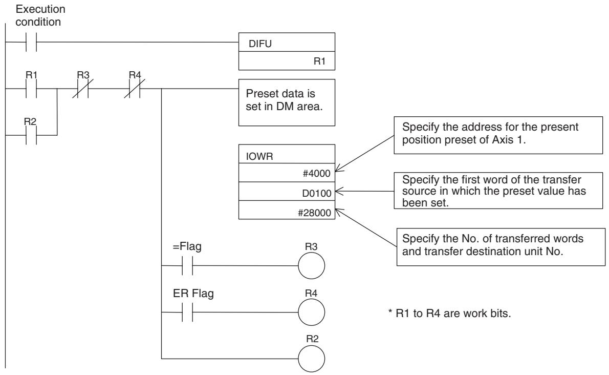
Setting Content [DM]
![OMRON CJ1W-MCH71 - Setting Content [DM] - 1](/content/2024/12/168263/images/6b7b288a10bf679476a09f120717b2bd9907a0891468e953cc5c493dbba30bef.jpg)
Caution
Executing the present position preset of a master axis during execution of synchronization with Feedback value specified in the master axis classification causes the MC Unit to operate the slave axis misconceiving that the master axis moved from the position before the preset to the one after the preset.
4-8 Servo Parameter
4-8-1 Servo Parameter Overview
Parameters in the servo driver can be edited using the Support Tool for MC Unit. It is also possible to read or write data from or to the servo driver using IORD/IOWR instructions of the CPU Unit.
These functions enable the PLC to manage the parameters of the servo driver.
Refer to the servo driver's manual for more details.
Note
Servo parameters operate with the setting saved in the servo driver. Therefore, it will be required to setup parameters of a driver when the driver is replaced.
Basic Procedures for Using CX-Motion-MCH Support Software
-
Connect the servo driver and Motion Control Unit.
-
Select the servo parameters in the project tree and select Online - Transfer- From Servo from the menu bar, click the icon in the toolbar, or right-click and select Transfer - From Servo from the pop-up menu to read the parameters from the servo drive to the computer.
- If data is to be edited offline, load the CX-Motion-MCH file saved in the computer.
- If the servo driver parameters are saved in the Motion Control Unit, select the servo parameters in the project tree and select Online - Transfer - From MC from the menu bar, click the icon in the toolbar, or right-click and select Transfer - From MC from the pop-up menu to read the parameters from the Motion Control Unit to the computer.
- Select the servo parameters in the project tree and select Online - Transfer - To MC from the menu bar, click the icon in the toolbar, or right-click and select Transfer - To MC from the pop-up menu to write the parameters from the computer to the Motion Control Unit.
Transfer Using IORD/ IOWR Instructions
Specify the address (7000 Hex - 78FF Hex) corresponding to the parameter No. (Pn000 - Pn8FF) of the serve driver. The three rightmost digits of the MC Unit address should match with the parameter No.
| Parameter No. | MC Unit Address |
| Pn000 | 7000 Hex |
| Pn001 | 7001 Hex |
| : | : |
| Pn8FF | 78FFHex |
Note For details on IORD/IOWR instructions, refer to 5-2 IOWR Instruction to Transfer Data (Page 221) and 5-3 IORD Instruction to Transfer Data (Page 228).
4-8-2 Data Configuration and Contents of Servo Parameters
The parameters with the combination of W-series servo driver and NS115 are classified as shown below.
| Classification | Shade in the list |
| Parameters exclusively for the linear motor | |
| Parameters of unused functions | |
| Parameters to be overwritten by the MC Unit | |
| Parameters that operate only with fixed values | Fixed value |
S: System reserved constant
R: Reserved constant (Do not change the setting.)
N: Disable constant (Do not change the setting because nothing will be changed.)
: Always enabled (Called Online User Constant)
Enable when DEN = 1 (Do not change when DEN = 0. If changed, proper operations are not guaranteed.) (Called Online User Constant)
: Restoring the power/CONFIG is required. (Called Offline User Constant)
| Type | User constant No. | Name | Size | Unit | Lower limit | Upper limit | the Support Tool initial value | En- able | |||
| Pn000 | Basic function selection switch | 2 | --- | 0000H | 1FF1H | 0000H | Δ | ||||
| 0 | Rotation direction select | 0 | CCW direction as forward rotation | 0 | Δ | ||||||
| 1 | CW direction as forward rotation | Δ | |||||||||
| 1 | Control method | 0-B | Setting has no effect. Do not set. | 0 | Δ | ||||||
| 2 | Axis address | 0-F | Sets an axis address for servo pack. | 0 | Δ | ||||||
| 3 | Rotary/Linear startup select (Without an encoder) | 0 | Starts as a rotary type. | 0 | Δ | ||||||
| 1 | Starts as a linear type. | ||||||||||
| Pn001 | Advanced function selection switch 1 | 2 | --- | 0000H | 1122H | 0000H | Δ | ||||
| 0 | Stopping method in case of servo-OFF or servo alarm] | 0 | Stops the motor using the dynamic brake (DB). | 0 | Δ | ||||||
| 1 | Stops the motor using the dynamic brake (DB), and then cancels the DB. | ||||||||||
| 2 | Makes the motor free-run status without using DB. | ||||||||||
| 1 | Stop method in case of Over travel (OT) | 0 | The same stopping method as for Pn001.0. | 0 | Δ | ||||||
| 1 | Makes the motor decelerate to stop with the torque set in Pn406 as maximum torque, and the motor will be in servo-lock state. | ||||||||||
| 2 | Makes the motor decelerate to stop with the torque set in Pn406 as maximum torque, and the motor will be in free-run state. | ||||||||||
| 2 | AC/DC power supply input select | 0 | DC power supply input not supported: Input AC power supply to L1, L2, (or L3) terminal. | 0 | Δ | ||||||
| 1 | DC power supply input supported: Input DC power supply to (+) 1(-) terminal. | ||||||||||
| 3 | Warning code output select | 0 | AL01, ALO2, and ALO3 output only alarm codes. | 0 | Δ | ||||||
| 1 | AL01, ALO2, and ALO3 output both alarm codes and warning codes. When outputting the warning codes, the ALM signal output stays ON (Normal). | ||||||||||
| Pn002 | Advanced function selection switch 2 | 2 | --- | 0000H | 4113H | 0000H | Δ | ||||
| 0 | Speed/position control option (T-REF allocation) | 0 | Nil | 0 | Δ | ||||||
| 1 | Uses T-REF as external torque limit input. | ||||||||||
| 2 | Uses T-REF as torque feed forward input. | ||||||||||
| 3 | Uses T-REF terminal as external torque limit input when P-CL and N-CL are enabled. | ||||||||||
| 1 | Torque control option (V-REF allocation) | 0 | Nil | 0 | Δ | ||||||
| 1 | Uses V-REF as external speed limit input. | ||||||||||
| 2 | Absolute encoder usage | 0 | Uses an absolute encoder as an absolute encoder. | 0 | Δ | ||||||
| 1 | Uses an absolute encoder as an incremental encoder. | ||||||||||
| 3 | Fully-closed PG pulse usage | 0 | Not Used | 0 | Δ | ||||||
| 1 | Uses without phase-C. | ||||||||||
| 2 | Uses with phase-C. | ||||||||||
| 3 | Uses in reverse rotation mode without phase-C. | ||||||||||
| 4 | Use as reverse rotation mode with phase-C. | ||||||||||
| Pn003 | Advanced function selection switch 3 | 2 | --- | 0000H | 00FFH | 0002H | ● | ||||
| 0 | Analog monitor 1 | 0 | Motor rotation speed Rotary: 1 V/1000 r/min, Linear: 1 V/1000 mm/s | 2 | ● | ||||||
| 1 | Speed command Rotary: 1 V/1000 r/min, Lin- ear: 1 V/1000 mm/s | ||||||||||
| 2 | Torque/thrust command: 1 V/100% | ||||||||||
| 3 | Position error: 0.05 V/1 command unit | ||||||||||
| 4 | Position error: 0.05 V/100 command unit | ||||||||||
| 5 | Command pulse frequency [r/min conver- sion] Rotary: 1 V/1000 r/min, Linear: 1 V/ 1000 mm/s | ||||||||||
| 6 | Motor rotation speed × 4 Rotary: 1 V/250 r/min × 10 Linear: 1 V/100 mm/s | ||||||||||
| 7 | Motor rotation speed × 8 Rotary: 1 V/125 r/min × 100 Linear: 1 V/10 mm/s | ||||||||||
| 8R | Reserved | ||||||||||
| 9R | Reserved | ||||||||||
| AR | Reserved | ||||||||||
| BR | Reserved | ||||||||||
| CR | Reserved | ||||||||||
| DR | Reserved | ||||||||||
| ER | Reserved | ||||||||||
| FR | Reserved | ||||||||||
| 1 | Analog monitor 2 | 0-F | Same as above | 0 | ● | ||||||
| 2 | Reserved | --- | 0 | ||||||||
| 3 | Reserved | --- | 0 | ||||||||
| Pn004 | S | Reserved | 2 | --- | 0000H | 1210H | 0200H | △ | |||
| 0 | Reserved | --- | 0 | ||||||||
| 1R | Reserved constant | 0 | 0 | △ | |||||||
| 1 | |||||||||||
| 2R | Reserved constant | 0 | 0 Automatically set to 2 | △ | |||||||
| 1 | |||||||||||
| 3R | Reserved constant | 0 | 0 | △ | |||||||
| 1 | |||||||||||
| Pn005 | Advanced function selection switch 5 | 2 | --- | 0000H | 0001H | 0000H | △ | ||||
| 0 | Brake control function select | 0 | Controls the brake by servo. | 0 | △ | ||||||
| 1 | Controls the brake by controller. | ||||||||||
| 1 | Reserved | --- | 0 | ||||||||
| 2 | Reserved | --- | 0 | ||||||||
| 3 | Reserved | --- | 0 | ||||||||
| Linear | Pn080 | Function select application switch | 2 | --- | 0000H | 0011H | 0000H | △ | |||
| 0 | Pole sensor select | 0 | With | 0 | △ | ||||||
| 1 | Without | ||||||||||
| 1 | Motor rotation direction select | 0 | Phase A advances in direction order of phases U, V, and W. | 0 | △ | ||||||
| 1 | Phase B advances in direction order of phases U, V, and W. | ||||||||||
| 2 | Reserved | --- | 0 | ||||||||
| 3 | Reserved | --- | 0 | ||||||||
| Pn100 | Speed loop gain | 2 | Hz | 1 | 2000 | 40 | ● | ||||
| Pn101 | Speed loop integration time constant | 2 | 0.01 ms | 15 | 51200 | 2000 | ● | ||||
| Pn102 | Position loop gain | 2 | 1/s | 1 | 2000 | 40 | ● | ||||
| Pn103 | Inertia ratio | 2 | % | 0 | 10000 | 0 | ● | ||||
| Pn104 | Speed loop gain 2 | 2 | Hz | 1 | 2000 | 40 | ● | ||||
| Pn105 | Speed loop integration time constant 2 | 2 | 0.01 ms | 15 | 51200 | 2000 | ● | ||||
| Pn106 | Position loop gain 2 | 2 | 1/s | 1 | 2000 | 40 | ● | ||||
| Rotary | Pn107 | Bias | 2 | r/min | 0 | 10000 | 0 | ● | |||
| Pn108 | Bias additional width | 2 | Pulse | 0 | 250 | 7 | ● | ||||
| Pn109 | Feed forward | 2 | % | 0 | 100 | 0 | ● | ||||
| Pn10A | Feed forward filter time constant | 2 | 0.01 ms | 0 | 6400 | 0 | ● | ||||
| Pn10B | Advanced gain-related switch | 2 | --- | --- | --- | 0000H | ● | ||||
| 0 | Mode switch select | 0 | Internal torque command is the switching condition.(Level setting: Pn10C) | 4 | ● | ||||||
| 1 | Speed command is the switching condi-tion.(Level setting: Pn10D) | ||||||||||
| 2 | Acceleration is the switching condition.(Level setting: Pn10E) | ||||||||||
| 3 | Error pulse is the switching condition.(Level setting: Pn10F) | ||||||||||
| 4 | No mode switching function | ||||||||||
| 1 | Speed loop control method | 0 | PI control | 0 | ● | ||||||
| 1 | IP control | ||||||||||
| 2 | Reserved | --- | 0 | ||||||||
| 3R | Reserved | 0 | --- | 0 | |||||||
| 1 | --- | ||||||||||
| 2 | --- | ||||||||||
| Pn10C | Mode switch (Torque command) | 2 | % | 0 | 800 | 200 | ● | ||||
| Rotary | Pn10D | Mode switch (Speed command) | 2 | r/min | 0 | 10000 | 0 | ● | |||
| Rotary | Pn10E | Mode switch (Acceleration) | 2 | 10 r/ min/s | 0 | 3000 | 0 | ● | |||
| Pn10F | Mode switch (Error pulse) | 2 | Pulse | 0 | 10000 | 0 | ● | ||||
| Pn110 | Real-time auto tuning-related switch | 2 | --- | 0000H | 3212H | 0010H | ● | ||||
| 0 | Online auto tuning method | 0 | Tuning just at beginning of an operation. | 0 | ● | ||||||
| 1 | Always tuning | ||||||||||
| 2 | No auto tuning | ||||||||||
| 1 | Speed FB compensation function select | 0 | With | 1 | ● | ||||||
| 1 | Without | ||||||||||
| 2 | Viscous friction compen-sation function select | 0 | Friction compensation: Nil | 0 | ● | ||||||
| 1 | Friction compensation: Small | ||||||||||
| 2 | Friction compensation: Large | ||||||||||
| 3R | Reserved | 0 | --- | 0 | ● | ||||||
| 1 | --- | ||||||||||
| 2 | --- | ||||||||||
| 3 | --- | ||||||||||
| Pn111 | Speed FB compensation | 2 | --- | 1 | 100 | 100 | ● | ||||
| Pn112 | R | Reserved | 2 | % | 0 | 1000 | 100 | ● | |||
| Pn113 | R | Reserved | 2 | 0.1 Hz | 0 | 10000 | 1000 | ● | |||
| Pn114 | R | Reserved | 2 | --- | 0 | 400 | 200 | ● | |||
| Pn115 | R | Reserved | 2 | 0.1 ms | 0 | 1000 | 32 | ● | |||
| Pn116 | R | Reserved | 2 | 0.1 ms | 0 | 1000 | 16 | ● | |||
| Pn117 | R | Reserved | 2 | % | 20 | 100 | 100 | ● | |||
| Pn118 | R | Reserved | 2 | % | 50 | 100 | 100 | ● | |||
| Pn119 | R | Reserved | 2 | 1/s | 1 | 2000 | 60 | ● | |||
| Pn11A | R | Reserved | 2 | 0.1% | 1 | 2000 | 1000 | ● | |||
| Pn11B | R | Reserved | 2 | Hz | 1 | 150 | 50 | ● | |||
| Pn11C | R | Reserved | 2 | Hz | 1 | 150 | 70 | ● | |||
| Pn11D | R | Reserved | 2 | % | 0 | 150 | 100 | ● | |||
| Pn11E | R | Reserved | 2 | % | 0 | 150 | 100 | ● | |||
| Pn11F | Position integration time constant | 2 | ms | 0 | 2000 | 0 | ● | ||||
| Pn120 | R | Reserved | 2 | 0.01 ms | 0 | 51200 | 0 | ● | |||
| Pn121 | R | Reserved | 2 | Hz | 1 | 250 | 50 | ● | |||
| Pn122 | R | Reserved | 2 | Hz | 0 | 250 | 0 | ● | |||
| Pn123 | R | Reserved | 2 | % | 0 | 100 | 0 | ● | |||
| Linear | Pn180 | Bias | 2 | mm/s | 0 | 450 | 0 | ● | |||
| Linear | Pn181 | Mode switch (Speed Command) | 2 | mm/s | 0 | 5000 | 0 | ● | |||
| Linear | Pn182 | Mode switch (Acceleration rate) | 2 | mm/s2 | 0 | 3000 | 0 | ● | |||
| Pn200 | S | Position control command mode select switch | 2 | --- | 0000H | 1239H | 0100H | Δ | |||
| 0N | Command pulse mode | 0-9 | Disabled | 0 | Δ | ||||||
| 1N | Clear signal mode | 0-3 | Disabled | 0 | Δ | ||||||
| 2S | Clear operation | 1 | Does not clear the error counter.(Cleared only with the CLR signal) | 0 Automatically set to 1 | Δ | ||||||
| Other | Do not set. (It is automatically set to 1.) | ||||||||||
| 3N | Filter select | 0-1 | Disabled | 0 | Δ | ||||||
| Rotary | Pn201 | PG dividing ratio | 2 | --- | 16 | 16384 | 16384 | Δ | |||
| Pn202 | Electronic gear ratio (numerator) | 2 | --- | 1 | 65535 | 1 | Δ | ||||
| Pn203 | Electronic gear ratio (denominator) | 2 | --- | 1 | 65535 | 1 | Δ | ||||
| Pn204 | Reserved | 2 | 0.01 ms | 0 | 6400 | 0 | ● | ||||
| Rotary | Pn205 | Multi-turns limit setting *1 | 2 | rev | 0 | 65535 | 65535 | Δ | |||
| Rotary | Pn206 | No. of full-closed pulses | 2 | P/R | 25 | 65535 | 16384 | Δ | |||
| Pn207 | S | Position command function switch | 2 | --- | 0000H | 0011H | 0010H | Δ | |||
| 0 | Reserved | 0 | --- | 0 | Δ | ||||||
| 1 | --- | ||||||||||
| 1S | Position control option | 1 | Uses V-REF as the speed feed forward input. | 1 | Δ | ||||||
| 0 | Do not set. (It is automatically set to 1.) | ||||||||||
| 2-3 | Reserved | --- | 0 | ||||||||
| Pn208 | Reserved | 2 | 0.01 ms | 0 | 6400 | 0 | |||||
| Linear | Pn280 | Linear scale pitch | 2 | um | 0 | 65535 | 0 | Δ | |||
| Linear | Pn281 | Encoder output resolution | 2 | Pulse/ Scale pitch (Pn280) | 1 | 256 | 20 | Δ | |||
| Pn300 | N | Speed command input gain | 2 | 0.01V/ Rated speed | 15 | 3000 | 600 | ● | |||
| Rotary | Pn301 | N | Internal speed setting 1 | 2 | r/min | 0 | 10000 | 100 | ● | ||
| Rotary | Pn302 | N | Internal speed setting 2 | 2 | r/min | 0 | 10000 | 200 | ● | ||
| Rotary | Pn303 | N | Internal speed setting 3 | 2 | r/min | 0 | 10000 | 300 | ● | ||
| Rotary | Pn304 | JOG speed | 2 | r/min | 0 | 10000 | 500 | ● | |||
| Pn305 | Soft start acceleration time | 2 | ms | 0 | 10000 | 0 | ● | ||||
| Pn306 | Soft start deceleration time | 2 | ms | 0 | 10000 | 0 | ● | ||||
| Pn307 | Speed command filter time constant | 2 | 0.01 ms | 0 | 65535 | 40 | ● | ||||
| Pn308 | Speed FB filter time constant | 2 | 0.01 ms | 0 | 65535 | 0 | ● | ||||
| Linear | Pn380 | N | Internal speed setting 1 | 2 | mm/s | 0 | 5000 | 10 | ● | ||
| Linear | Pn381 | N | Internal speed setting 2 | 2 | mm/s | 0 | 5000 | 20 | ● | ||
| Linear | Pn382 | N | Internal speed setting 3 | 2 | mm/s | 0 | 5000 | 30 | ● | ||
| Linear | Pn383 | JOG speed | 2 | mm/s | 0 | 5000 | 50 | ● | |||
| Pn400 | N | Torque/Thrust gain | 2 | 0.1 V/ Rated torque | 10 | 100 | 30 | ● | |||
| Pn401 | Torque/Thrust filter time constant | 2 | 0.01 ms | 0 | 65535 | 100 | ● | ||||
| Rotary | Pn402 | Forward torque limit | 2 | % | 0 | 800 | 800 | ● | |||
| Rotary | Pn403 | Reverse torque limit | 2 | % | 0 | 800 | 800 | ● | |||
| Pn404 | External input forward torque/Thrust limit | 2 | % | 0 | 800 | 100 | ● | ||||
| Pn405 | External input reverse torque/Thrust limit | 2 | % | 0 | 800 | 100 | ● | ||||
| Pn406 | Emergency stop torque/Thrust | 2 | % | 0 | 800 | 800 | ● | ||||
| Rotary | Pn407 | Speed limit in torque control | 2 | r/min | 0 | 10000 | 10000 | ● | |||
| Pn408 | Torque/Thrust control function switch | 2 | --- | 0000H | 0001H | 0000H | ● | ||||
| 0 | Notch filter function select | 0 | Nil | 0 | ● | ||||||
| 1 | Uses the notch filter for torque command. | ||||||||||
| 1 | Reserved | --- | 0 | ||||||||
| 2 | Reserved | --- | 0 | ||||||||
| 3 | Reserved | --- | 0 | ||||||||
| Pn409 | Notch filter frequency | 2 | Hz | 50 | 2000 | 2000 | ● | ||||
| Linear | Pn480 | Speed limit during thrust control | 2 | mm/s | 0 | 5000 | 5000 | ● | |||
| Linear | Pn481 | Magnetic pole detection speed loop gain | 2 | Hz | 1 | 2000 | 40 | ● | |||
| Linear | Pn482 | Magnetic pole detection speed loop integral time | 2 | 0.01 ms | 15 | 51200 | 3000 | ● | |||
| Linear | Pn483 | Forward rotation thrust limit | 2 | % | 0 | 800 | 30 | ● | |||
| Linear | Pn484 | Reverse rotation thrust limit | 2 | % | 0 | 800 | 30 | ● | |||
| Pn500 | Positioning completed width | 2 | Com-mand unit (pulse for /COIN output) | 0 | 250 | 7 | ● | ||||
| Rotary | Pn501 | Clamp at zero level | 2 | r/min | 0 | 10000 | 10 | ● | |||
| Rotary | Pn502 | Rotation detection level | 2 | r/min | 1 | 10000 | 20 | ● | |||
| Rotary | Pn503 | Speed conformity signal detection width | 2 | r/min | 0 | 100 | 10 | ● | |||
| Pn504 | NEAR signal width | 2 | Com-mand unit (pulse for /NEAR output) | 1 | 250 | 7 | ● | ||||
| Pn505 | Error counter overflow level | 2 | 256 pulse | 1 | 32767 | 1024 | ● | ||||
| Pn506 | Brake command-Servo OFF delay time | 2 | 10 ms | 0 | 50 | 0 | ● | ||||
| Rotary | Pn507 | Brake command output speed level | 2 | r/min | 0 | 10000 | 100 | ● | |||
| Pn508 | Servo OFF-Brake command wait time | 2 | 10 ms | 10 | 100 | 50 | ● | ||||
| Pn509 | Temporary power interruption hold time | 2 | ms | 20 | 1000 | 20 | ● | ||||
| Type | User constant No. | Name | Size | Unit | Lower limit | Upper limit | the Support Tool initial value | En- able | ||||
| Sequence related con-stant | Pn50A | S | Input signal select 1 | 2 | --- | 0000H | FFFFH | 2881H | Δ | |||
| \(0^S\) | Input signal allocation mode | 1 | Custom setting | 1 | ||||||||
| 0 | Do not set. (It is automatically set to 1.) | |||||||||||
| \(1^S\) | /S-ON signal allocation | 8 | Do not set. (It is automatically set to 8.) | 8 | ||||||||
| \(2^S\) | /P-CON signal allocation | 8 | Do not set. (It is automatically set to 8.) | 8 | ||||||||
| 3 | P-OT signal allocation | 0 | Input from SI0 (CN1-40) input terminal. | 2 | Δ | |||||||
| 1 | Input from SI1 (CN1-41) input terminal. | |||||||||||
| 2 | Input from SI2 (CN1-42) input terminal. | |||||||||||
| 3 | Input from SI3 (CN1-43) input terminal. | |||||||||||
| 4 | Input from SI4 (CN1-44) input terminal. | |||||||||||
| 5 | Input from SI5 (CN1-45) input terminal. | |||||||||||
| 6 | Input from SI6 (CN1-46) input terminal. | |||||||||||
| 7 | Fixed at enable the signal. | |||||||||||
| 8 | Fixed at disable the signal. | |||||||||||
| 9 | Input reverse signal from SI0 (CN1-40) input terminal. | |||||||||||
| A | Input reverse signal from SI1 (CN1-41) input terminal. | |||||||||||
| B | Input reverse signal from SI2 (CN1-42) input terminal. | |||||||||||
| C | Input reverse signal from SI3 (CN1-43) input terminal. | |||||||||||
| D | Input reverse signal from SI4 (CN1-44) input terminal. | |||||||||||
| E | Input reverse signal from SI5 (CN1-45) input terminal. | |||||||||||
| F | Input reverse signal from SI6 (CN1-46) input terminal. | |||||||||||
| Pn50B | S | Input signal select 2 | 2 | --- | 0000H | FFFFH | 8883H | Δ | ||||
| \(0^S\) | N-OT signal allocation | 0-F | Same as above. | 3 | Δ | |||||||
| \(1^S\) | /ALM-RST signal alloca-tion | 8 | Do not set. (It is automatically set to 8.) | 8 | ||||||||
| \(2^S\) | /P-CL signal allocation | 0-F | Allocation of forward current limiting signal. | 8 | Δ | |||||||
| \(3^S\) | N-CL signal allocation | 0-F | Allocation of reverse current limiting signal. | 8 | Δ | |||||||
| Pn50C | S | Input signal select 3 | 2 | --- | 0000H | FFFFH | 8888H | |||||
| \(0^S\) | /SPD-D signal allocation | 8 | Same as above. Do not set. (It is automat-cally set to 8.) | 8 | ||||||||
| \(1^S\) | /SPD-A signal allocation | 8 | Same as above. Do not set. (It is automat-cally set to 8.) | 8 | ||||||||
| \(2^S\) | /SPD-B signal allocation | 8 | Same as above. Do not set. (It is automat-cally set to 8.) | 8 | ||||||||
| \(3^S\) | /C-SEL signal allocation | 8 | Same as above. Do not set. (It is automat-cally set to 8.) | 8 | ||||||||
| Pn50D | S | Input signal select 4 | 2 | --- | 0000H | FFFFH | 8888H | |||||
| \(0^S\) | /ZCLAMP signal alloca-tion | 8 | Same as above. Do not set. (It is automat-cally set to 8.) | 8 | ||||||||
| \(1^S\) | /INHIBIT signal alloca-tion | 8 | Same as above. Do not set. (It is automat-cally set to 8.) | 8 | ||||||||
| \(2^S\) | /G-SEL signal allocation | 8 | Same as above. Do not set. (It is automat-cally set to 8.) | 8 | ||||||||
| \(3^S\) | P-DET signal allocation | 8 | Same as above. Do not set. (It is automat-cally set to 8.) | 8 | ||||||||
| Type | User constant No. | Name | Size | Unit | Lower limit | Upper limit | the Support Tool initial value | En- able | |||
| Sequence related con-stant | Pn50E | Output signal select 1 | 2 | --- | 0000H | 3333H | 3001H | Δ | |||
| 0 | /COIN signal allocation | 0 | Not used | 1 | Δ | ||||||
| 1 | Output from SO1 (CN-25, 26) output termi-nal. | ||||||||||
| 2 | Output from SO2 (CN-27, 28) output termi-nal. | ||||||||||
| 3 | Output from SO3 (CN-29, 30) output termi-nal. | ||||||||||
| 1 | /V-CMP signal allocation | 0-3 | Same as above. | 0 | Δ | ||||||
| 2 | /TGON signal allocation | 0-3 | Same as above. | 0 | Δ | ||||||
| 3 | /S-RDY signal allocation | 0-3 | Same as above. | 3 | Δ | ||||||
| Pn50F | Output signal select 2 | 2 | --- | 0000H | 3333H | 0200H | Δ | ||||
| 0 | /CLT signal allocation | 0-3 | Same as above. | 0 | Δ | ||||||
| 1 | /VLT signal allocation | 0-3 | Same as above. | 0 | Δ | ||||||
| 2 | /BK signal allocation | 0-3 | Same as above. | 2 | Δ | ||||||
| 3 | /WARN signal allocation | 0-3 | Same as above. | 0 | Δ | ||||||
| Pn510 | Output signal select 3 | 2 | --- | 0000H | 0033H | 0000H | Δ | ||||
| 0 | /NEAR signal allocation | 0-3 | Same as above. | 0 | Δ | ||||||
| 1 | /C-PHASE signal alloca-tion | 0-3 | Same as above. | 0 | Δ | ||||||
| 2 | Reserved | 0 | --- | 0 | |||||||
| 3 | Reserved | 0 | --- | 0 | |||||||
| Type | User constant No. | Name | Size | Unit | Lower limit | Upper limit | the Support Tool initial value | Enable | ||||
| Sequence related constant | Pn511 | Output signal select 5 | 2 | --- | 0000H | FFFFH | 6541H | Δ | ||||
| 0 | /DEC signal allocation | 0 | Input from SI0 (CN1-40) input terminal. | 1 | Δ | |||||||
| 1 | Input from SI1 (CN1-41) input terminal. | |||||||||||
| 2 | Input from SI2 (CN1-42) input terminal. | |||||||||||
| 3 | Input from SI3 (CN1-43) input terminal. | |||||||||||
| 4 | Input from SI4 (CN1-44) input terminal. | |||||||||||
| 5 | Input from SI5 (CN1-45) input terminal. | |||||||||||
| 6 | Input from SI6 (CN1-46) input terminal. | |||||||||||
| 7 | Fixed at enable the signal. | |||||||||||
| 8 | Fixed at disable the signal. | |||||||||||
| 9 | Input reverse signal from SI0 (CN1-40) input terminal. | |||||||||||
| A | Input reverse signal from SI1 (CN1-41) input terminal. | |||||||||||
| B | Input reverse signal from SI2 (CN1-42) input terminal. | |||||||||||
| C | Input reverse signal from SI3 (CN1-43) input terminal. | |||||||||||
| D | Input reverse signal from SI4 (CN1-44) input terminal. | |||||||||||
| E | Input reverse signal from SI5 (CN1-45) input terminal. | |||||||||||
| F | Input reverse signal from SI6 (CN1-46) input terminal. | |||||||||||
| 1 | /EXT1 signal allocation | 4 | Input from SI4 (CN1-44) input terminal. | 4 | Δ | |||||||
| 5 | Input from SI5 (CN1-45) input terminal. | |||||||||||
| 6 | Input from SI6 (CN1-46) input terminal. | |||||||||||
| 7 | Fix the signal 'enable'. | |||||||||||
| 8 | Fix the signal 'disable'. | |||||||||||
| D | Input reverse signal from SI4 (CN1-44) input terminal. | |||||||||||
| E | Input reverse signal from SI5 (CN1-45) input terminal. | |||||||||||
| F | Input reverse signal from SI6 (CN1-46) input terminal. | |||||||||||
| 0-39-F | Fixed at disable the signal. | |||||||||||
| 2 | /EXT2 signal allocation | 0-F | Same as above. | 5 | Δ | |||||||
| 3 | /EXT3 signal allocation | 0-F | Same as above. | 6 | Δ | |||||||
| Pn512 | Output signal reverse | 2 | --- | 0000H | 0111H | 0000H | Δ | |||||
| 0 | Output signal reverse for SO1 (CN1-25, 26) | 0 | Not reversed | 0 | Δ | |||||||
| 1 | Reversed | |||||||||||
| 1 | Output signal reverse for SO1 (CN1-27, 28) | 0,1 | Same as above. | 0 | Δ | |||||||
| 2 | Output signal reverse for SO1 (CN1-29, 30) | 0,1 | Same as above. | 0 | Δ | |||||||
| 3 | Reserved | 0 | --- | 0 | Δ | |||||||
| Rotary | Pn51A | Motor-load deviation level between positions | 2 | Pulse | 1 | 32767 | 10 | ● | ||||
| Pn51E | Deviation counter overflow warning detection level | 2 | % | 0 | 100 | 100 | ● | |||||
| Linear | Pn580 | Clamp level at zero. | 2 | mm/s | 0 | 5000 | 10 | ● | ||||
| Linear | Pn581 | Rotation detection level | 2 | mm/s | 1 | 5000 | 20 | ● | ||||
| Linear | Pn582 | Speed conformity signal detection width | 2 | mm/s | 0 | 100 | 10 | ● | ||||
| Linear | Pn583 | Brake command output speed level | 2 | mm/s | 0 | 5000 | 100 | ● | ||||
| Type | User constant No. | Name | Size | Unit | Lower limit | Upper limit | the Support Tool initial value | En- able | |||
| Pn600 | Regenerative resistor capacity (set the capacity when connecting an external regenerative resistor) | 2 | 10 W | 0 | 1000 | 0 | ● | ||||
| Pn601 | R | Reserved constant | 2 | --- | 0 | 1000 | 0 | ● | |||
| Communications | Pn800 | Communication control | 2 | --- | 0000H | 0F73H | 0000H | ● | |||
| 0 | MECHATROLINK-II communications check mask(For debugging) | 0 | Normal | 0 | ● | ||||||
| 1 | Communication error (A.E6) ignored. | ||||||||||
| 2 | WDT error (A.E5) ignored | ||||||||||
| 3 | Communication error (A.E6) and WDT error(A.E5) both ignored. | ||||||||||
| 1 | Warning check mask(For debugging) | 0 | Normal | 0 | ● | ||||||
| 1 | Data setting warning (A.94) ignored | ||||||||||
| 2 | Command warning (A.95) ignored. | ||||||||||
| 3 | A.94 and A.95 ignored. | ||||||||||
| 4 | Communication error (A.96) ignored. | ||||||||||
| 5 | A.94 and A.96 ignored. | ||||||||||
| 6 | A.95 and A.96 ignored. | ||||||||||
| 7 | A.94, A95, and A96 ignored. | ||||||||||
| 2 | Communication error count when single trans-fer | 0-F | Detect the communication error (A.E6) twice in a row plus the setting value. | 0 | ● | ||||||
| 3 | Reserved | 0 | --- | 0 | |||||||
| Sequencerelations | Pn801 | Advanced function select 6 (Soft LS) | 2 | --- | 0000H | 0113H | 0003H | ● | |||
| 0 | Software limit function | 0 | Software limit enabled | 3 | ● | ||||||
| 1 | Forward software limit disabled | ||||||||||
| 2 | Reverse software limit disabled | ||||||||||
| 3 | Both Forward/reverse software limits dis-abled | ||||||||||
| 1 | Reserved | 0 | --- | 0 | ● | ||||||
| 2 | Software limit checked by commands. | 0 | No software limit check by commands. | 0 | ● | ||||||
| 1 | Software limit check by a command is con-ducted. | ||||||||||
| 3 | Reserved | 0 | --- | 0 | |||||||
| Pn802 | Reserved constant | 2 | --- | 0000H | 0000H | 0000H | △ | ||||
| 0 | Reserved | 0 | --- | 0 | △ | ||||||
| 1 | Reserved | 0 | --- | 0 | △ | ||||||
| 2 | Reserved | 0 | --- | 0 | |||||||
| 3 | Reserved | 0 | --- | 0 | |||||||
| Pn803 | Origin position range | 2 | Com-mand unit | 0 | 250 | 10 | ● | ||||
| Position relations | Pn804Pn805 | Positive software limit value | 4 | Com-mand unit | -230+1 | 230-1 | 8192*99999 | ● | |||
| Pn806Pn807 | Negative software limit value | 4 | Com-mand unit | -230+1 | 230-1 | -8192*99999 | ● | ||||
| Pn808Pn809 | ABS PG origin position Offset *5 | 4 | Com-mand unit | -230+1 | 230-1 | 0 | ● | ||||
| Acceleration/ deceleration | Pn80A | First-stop linear acceleration constant. | 2 | 10000 Com-mand unit/s2 | 1 | 65535 | 100 | ○ | |||
| Pn80B | Second-stop linear acceleration con-stant. | 2 | 10000 Com-mand unit/s2 | 1 | 65535 | 100 | ○ | ||||
| Pn80C | Acceleration rate switching speed | 2 | 100 Com-mand unit/s2 | 0 | 65535 | 0 | ○ | ||||
| Pn80D | First-stop linear deceleration constant. | 2 | 10000 Com-mand unit/s2 | 1 | 65535 | 100 | ○ | ||||
| Pn80E | Second-stop linear deceleration con-stant. | 2 | 10000 Com-mand unit/s2 | 1 | 65535 | 100 | ○ | ||||
| Pn80F | Deceleration rate switching speed. | 2 | 100 Com-mand unit/s2 | 0 | 65535 | 0 | ○ | ||||
| Acceleration/ deceleration filter | Pn810 | Exponential acceleration/deceleration bias. | 2 | Com-mand unit/s2 | 0 | 32767 | 0 | ○ | |||
| Pn811 | Exponential acceleration/deceleration time constant | 2 | 0.1 ms | 0 | 5100 | 0 | ○ | ||||
| Pn812 | Moving average time | 2 | 0.1 ms | 0 | 5100 | 0 | ○ | ||||
| Monitor | Pn813 | Option monitor | 2 | --- | 0000H | 0099H | 0032H | ● | |||
| 0 | Option monitor 1 select | 0 | Follows the analog monitor 1 (Pn003.0) | 2 | ● | ||||||
| 1 | Follows the analog monitor 1 (Pn003.1) | ||||||||||
| 2 | Initial multi-turns data (IMTDATA) | ||||||||||
| 3 | Encoder count direct value (PGCNT: after multiplication by 4) | ||||||||||
| 4 | Motor PG initial multi-turns data direct value. | ||||||||||
| 5 | Motor PG counter direct value. | ||||||||||
| 6 | Motor PG count latch direct value. | ||||||||||
| 7 | Reserved | ||||||||||
| 8 | Full-closed PG counter direct value. | ||||||||||
| 9 | Full-closed PG counter latch direct value. | ||||||||||
| 1 | Option monitor 2 select | 0-9 | Same as above. | 3 | ● | ||||||
| 2 | Reserved | 0 | --- | 0 | |||||||
| 3 | Reserved | 0 | --- | 0 | |||||||
| Command supplement | Pn814 Pn815 | Final travel distance for external posi- tIoning | 4 | Com- mand unit | \( -2^{30}+1 \) | \( 2^{30}-1 \) | 100 | ○ | |||
| Pn816 | Origin return mode setting | 2 | --- | 0000H | 0001H | 0000H | ○ | ||||
| 0 | Origin return direction | 0 | Forward rotation direction | 0 | ○ | ||||||
| 1 | Reverse rotation direction | ||||||||||
| 1 | Reserved | 0 | --- | 0 | |||||||
| 2 | Reserved | 0 | --- | 0 | |||||||
| 3 | Reserved | 0 | --- | 0 | |||||||
| Pn817 | Origin return approach speed 1 | 2 | 100 Com- mand unit/s | 0 | 65535 | 50 | ○ | ||||
| Pn818 | Origin return approach speed 2 | 2 | 100 Com- mand unit/s | 0 | 65535 | 5 | ○ | ||||
| Pn819 Pn81A | Origin return final travel distance | 4 | Com- mand unit | \( -2^{30}+1 \) | \( 2^{30}-1 \) | 100 | ○ | ||||
| Pn81B | Backlash compensation amount | 2 | 0.1 Com- mand unit | -32768 | 32767 | 0000H | ● | ||||
| Pn81C | Reserved constant | 2 | --- | 0000H | |||||||
| Pn81D | Compensation function select | 2 | --- | 0000H | 0001H | 0000H | △ | ||||
| Pn81E | Input signal monitor select | 2 | --- | 0000H | 7777H | 0000H | ● | ||||
| 0 | IO12 allocation | 0 | No allocations | 0 | ● | ||||||
| 1 | Monitors SI0 (CN1-40) input terminal. | ||||||||||
| 2 | Monitors SI1 (CN1-41) input terminal. | ||||||||||
| 3 | Monitors SI2 (CN1-42) input terminal. | ||||||||||
| 4 | Monitors SI3 (CN1-43) input terminal. | ||||||||||
| 5 | Monitors SI4 (CN1-44) input terminal. | ||||||||||
| 6 | Monitors SI5 (CN1-45) input terminal. | ||||||||||
| 7 | Monitors SI6 (CN1-46) input terminal. | ||||||||||
| 1 | IO13 allocation | 0-7 | Same as above. | 0 | ● | ||||||
| 2 | IO14 allocation | 0-7 | Same as above. | 0 | ● | ||||||
| 3 | IO15 allocation | 0-7 | Same as above. | 0 | ● | ||||||
| Pn81F | Reserved constant | 2 | --- | 0000H | |||||||
| Pn820 Pn821 | Forward latch possible range | 4 | Com- mand unit | \( -2^{31} \) | \( 2^{31}-1 \) | 00000000H | ● | ||||
| Pn822 Pn823 | Reverse latch possible range | 4 | Com- mand unit | \( -2^{31} \) | \( 2^{31}-1 \) | 00000000H | ● | ||||
4-8-3 Motor Parameters
The values for the following parameters are automatically set when the motor model is selected on the Support Tool. Some of the parameters need to be adjusted in the following cases.
- When using an absolute encoder as an incremental encoder (related parameter: 9003h)
- When using the axis as an infinite length axis in the system with an absolute encoder (related parameter: 900Ch)
In the initial value column, the upper value is in hexadecimal and the lower value in parenthesis is in decimal.
| No. | Name | Configuration and explanation | Type | Initial value | Unit | Immediate updating |
| 9001 | No. of encoder pulses | 31 00No. of encoder pulses | Bit | 00000000(0) | --- | No |
| • Sets the No. of encoder pulses for 1 motor rotation.(Ex) With 13-bit encoder: 8192 pulses = 2000 HexWith 16-bit encoder: 65536 pulses = 10000 HexNote Selecting the motor model automatically sets this parameter. | ||||||
| 9002 | Encoder type | 15 00Encoder type | Bit | 0000 (0) | --- | No |
| • Sets the encoder type.0000 Hex: Incremental encoder0100 Hex: Absolute encoderNote Selecting the motor model automatically sets this parameter. | ||||||
| 9003 | Absolute encoder usage | 15 00Usage | Bit | 0000 (0) | --- | No |
| • Sets the usage of an absolute encoder.0000 Hex: Use it as an absolute encoder0100 Hex: Use it as an incremental encoderSupplementary:When using an absolute encoder as an incremental encoder, the present position does not show 0 at switching ON the MC Unit. This is a normal condition because the MC Unit is counting the initial incremental pulses of the absolute encoder. | ||||||
| 9004 | Rated rotation speed | 15 00Motor rated speed | Data | 0000 (0) | 100 r/min | No |
| • Sets the motor rated speed.Note Selecting the motor model automatically sets this parameter. | ||||||
| 9005 | Rated speed index | 15 00Speed index | Data | 0000 (0) | --- | No |
| • Sets the unit system for the rated speed.Note Make sure to set this parameter to 0000 Hex. | ||||||
| 9006 | Max. rapid speed | 15 00Max. speed | Data | 0000 (0) | 100 r/min | No |
| • Sets the max. speed of the motor.Note Selecting the motor model automatically sets this parameter. | ||||||
| 9007 | Max. rapid speed index | 15 00 Max. speed unit • Sets the unit system for the max. speed. Note Make sure to set this parameter to 0000 Hex. | Data | 0000 (0) | --- | No |
| 9008 | Rated torque (reserved) | 31 00 Rated torque • Sets the rated torque of the motor. Note Selecting the motor model automat- cally sets this parameter. | Data | 00000000 (0) | 0.0001 N·m | -- |
| 9009 | Max. torque (reserved) | 31 00 Max. torque • Sets the max. torque of the motor. Note Selecting the motor model automat- cally sets this parameter. | Data | 00000000 (0) | 0.0001 N·m | -- |
| 900A | Latch range (+) No. | 15 00 + Latch range • This is the address of + Latch range. Note Selecting the motor model automat- cally sets this parameter. Note Entering numerical value cannot change this parameter. | Data | 0000 (0) | --- | No |
| 900B | Latch range (-) No. | 15 00 - Latch range • This is the address of - Latch range. Note Selecting the motor model automat- cally sets this parameter. Note Entering numerical value cannot change this parameter. | Data | 0000 (0) | --- | No |
| 900C | Multi-turn limit | 15 00 Multi-turn • Sets the No. of multi-turns of an absolute encoder. When using an axis as an infinite length axis, make sure to set the same value set in Pn205 of the servo driver. • Setting range 0 to FFFF Hex (0 to 65535) | Data | FFFF (65535) | --- | No |
| 900D | Position loop gain address | 15 00Position loop gain addressThis is the address of the position loop gain.Note Selecting the motor model automatically sets this parameter.Note Entering numerical value cannot change this parameter. | Data | 0000 (0) | --- | No |
| 900E | Position loop gain index | 15 00Position loop gain indexSets the unit system for the position loop gain.Set 0000 Hex when the W Series and NS115 are combined, and set 0001h for W-series Servo Drivers with built-in communications. | Data | 0000 (0) | --- | No |
4-8-4 Setting Method Using Combination of W Series and NS115
This section explains the servo driver's parameter setting method with combination of W-series servo driver and NS115.
The following user constants are expressed as restricted constant, determined constant, expansion constant, and disabled constant.
Determined constant: To be reset to the settings in the following table if the value is outside of the setting value when the power is turned ON.
Approximately three seconds will be added during the re-setting.
Expansion constant: This is the parameter to expand a function when installing the NS115.
Disabled constant: Neither alarm nor warning occurs even when changed.
| User constant No. | Name | Content | Setting | Remark |
| Pn004.1 | Electronic gear conversion of the feedback count in position control | No conversion | 0 | Determined constant |
| Pn004.2 | Control mode switch | Execute | 1 | Determined constant |
| Pn004.3 | Access cycle S-shape filter | Disable | 0 | Determined constant |
| Pn200.2 | Clear operation | Cleared only with CLR command. | 1 | Determined constant |
| Pn207.1 | Position control option | Speed feed forward on V-REF | 1 | Determined constant |
| Pn50A.0 | Input allocation | Input signal custom setting | 1 | Determined constant |
| Pn50A.1 | /SVON | Disable | 8 | Determined constant |
| Pn50B.1 | /ALMRST | Disable | 8 | Determined constant |
| Pn50C | /SPD-D, -A, -B, /C-SEL | Disable | 8888 | Determined constant |
| Pn50D | /ZCLAMP, /INH, /G-SEL, /P-DET | Disable | 8888 | Determined constant |
| Pn002.3 | Full-closed encoder usage | Expansion constant | ||
| Pn005 | Advanced function select switch 5 | Expansion constant | ||
| Pn206 | No. of Full-closed encoder pulses | Expansion constant | ||
| Pn511 | Input signal select 5 | Expansion constant | ||
| Pn200.0 | Command pulse mode | 0 | Disabled constant | |
| Pn200.1 | Clear signal mode | 0 | Disabled constant | |
| Pn200.3 | Filter select | 0 | Disabled constant | |
| Pn300 | Speed command input gain | Disabled constant | ||
| Pn301,2,3 | Internal setting speed 1, 2, 3 | Disabled constant | ||
| Pn400 | Torque command input gain | Disabled constant |
I/O Signal (W-series CN1) Setting
The standard setting of I/O signals (CN1) when the NS115 is mounted is described below.
Make sure that it has been changed to the standard setting prior to use.
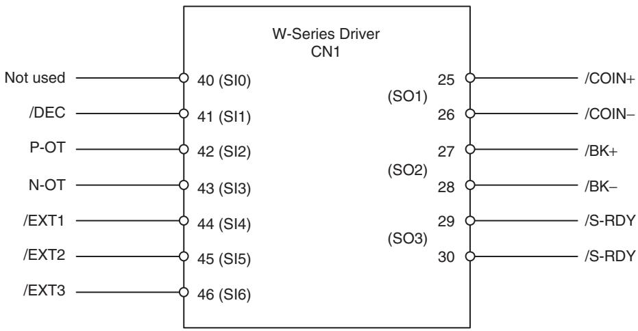
| User's constant No. | Content | W-series default setting | Default setting with NS115 mounted | the Support Tool initial value |
| Pn50A | Input signal select 1 | 8100H | 8881H | 2881H |
| Pn50B | Input signal select 2 | 6548H | 6588H | 8883H |
| Pn511 | Input signal select 5 | 8888H | 8888H | 6541H |
| Pn50E | Output signal select 1 | 3211H | 3211H | 3001H |
| Pn50F | Output signal select 2 | 0000H | 0000H | 0200H |
| Pn510 | Output signal select 3 | 0000H | 0000H | 0000H |
Expanded Function
The following functions will become available by mounting NS115.
1,2,3... 1. Full-closed control
2. Input signal select
Full-closed Control
The full-closed control setting can be performed using the following user constants.
| Type | User's constant No. | Name | Size | Unit | Lower limit | Upper limit | the Support Tool initial value | En- able | |||
| Function select con-stant | Pn002 | Advanced function select switch 2 | 2 | --- | 0000H | 4112H | 0000H | Δ | |||
| 3 | Full-closed encoder usage | 0 | Not used | 0 | Δ | ||||||
| 1 | Used without phase-C | ||||||||||
| 2 | Used with phase-C | ||||||||||
| 3 | Used in reverse rotation mode without phase-C | ||||||||||
| 4 | Used in reverse rotation mode with phase-C | ||||||||||
| Position rela-tions | Pn206 | No. of full-closed encoder pulses | 2 | P/R (×1) | 512 | 65535 | 16384 | Δ | |||
Related user's constant
| Pn202 | Electronic gear (numerator) |
| Pn203 | Electronic gear (denominator) |
- Full-closed encoder pulse mode 5V differential line driver output (EIA Standard RS-422A compliance)
- Full-closed encoder pulse signal mode Two pulses with phase difference of 90 degree: Phase-A, Phase-B Latch pulse (origin pulse): Phase-C (can be used) Maximum receivable frequency: 1 Mbps (per one phase)
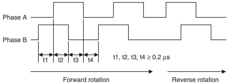
- Set the No. of full-closed encoder pulses per one motor rotation with the value (x1 multiplication).
- If an integer cannot be obtained, set the closest integer.
- There will be deviations in the speed monitors of position loop gain, feed forward, and command pulse, but no position deviation should result.
- The full-closed control does not support an absolute encoder, but an incremental encoder.
- If the encoder that is attached on the motor is an absolute encoder, the usage is the same as for an incremental encoder.
Setting for Reverse Rotations
| Motor rotation direction seen from the load side during forward rotation command | Phase relations of the full-closed PG input during forward rotation | Pn000.0 setting | Pn002.3 setting | Full-closed PG input phase relations during CCW direction rotation seen from the load side |
| CCW direction | Diagram 8.3 | 0 | 1, 2 | Diagram 8.3 |
| Diagram 8.4 | 3, 4 | Diagram 8.4 | ||
| CW direction | Diagram 8.3 | 1 | 1, 2 | Diagram 8.4 |
| Diagram 8.4 | 3, 4 | Diagram 8.3 | ||
| Full-closed PG input | Full-closed PG input | |||
| Phase A | Phase A | Time | ||
| Phase B | Phase B | Diagram 8.4 | ||
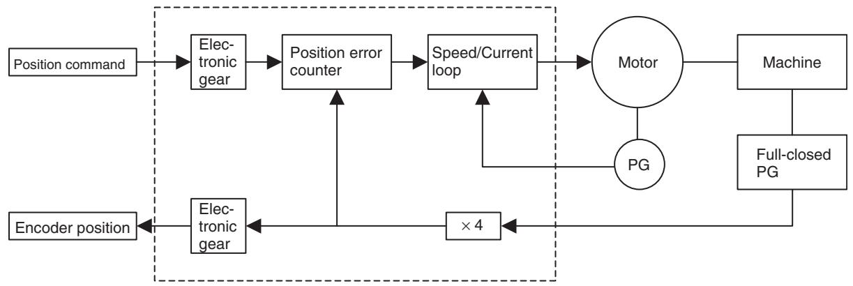
Electronic gear
Input Signal Select 5
Through the following user constants setting, it is possible to allocate the signals in the table below to the CN1 input signals.
| Type | User's constant No. | Name | Size | Unit | Lower limit | Upper limit | the Support Tool initial value | En- able | |
| Pn511 | Input signal select 5 | 2 | --- | 0000H | FFFFH | 6541H | Δ | ||
| 0 | /DEC signal allocation | 0 | Input from SI0 (CN1-40) input terminal | 1 | Δ | ||||
| 1 | Input from SI1 (CN1-41) input terminal | ||||||||
| 2 | Input from SI2 (CN1-42) input terminal | ||||||||
| 3 | Input from SI3 (CN1-43) input terminal | ||||||||
| 4 | Input from SI4 (CN1-44) input terminal | ||||||||
| 5 | Input from SI5 (CN1-45) input terminal | ||||||||
| 6 | Input from SI6 (CN1-46) input terminal | ||||||||
| 7 | Fixed at enabled the signal. | ||||||||
| 8 | Fixed at disabled the signal. | ||||||||
| 9 | Input reverse signal from SI0 (CN1-40) input terminal. | ||||||||
| A | Input reverse signal from SI1 (CN1-41) input terminal. | ||||||||
| B | Input reverse signal from SI2 (CN1-42) input terminal. | ||||||||
| C | Input reverse signal from SI3 (CN1-43) input terminal. | ||||||||
| D | Input reverse signal from SI4 (CN1-44) input terminal. | ||||||||
| E | Input reverse signal from SI5 (CN1-45) input terminal. | ||||||||
| F | Input reverse signal from SI6 (CN1-46) input terminal. | ||||||||
| 1 | /EXT1 signal allocation | 4 | Input from SI4 (CN1-44) input terminal. | 4 | Δ | ||||
| 5 | Input from SI5 (CN1-45) input terminal. | ||||||||
| 6 | Input from SI6 (CN1-46) input terminal. | ||||||||
| 7 | Fixed at enabled the signal. | ||||||||
| 8 | Fixed at disabled the signal. | ||||||||
| D | Input reverse signal from SI4 (CN1-44) input terminal | ||||||||
| E | Input reverse signal from SI5 (CN1-45) input terminal. | ||||||||
| F | Input reverse signal from SI6 (CN1-46) input terminal. | ||||||||
| 0-39-C | Fixed at disabled the signal. | ||||||||
| 2 | /EXT2 signal allocation | 0-F | Same as above. | 5 | Δ | ||||
| 3 | /EXT3 signal allocation | 0-F | Same as above. | 6 | Δ | ||||
4-9 CAM Data
CAM data indicates the entire CAM tables used in the commands CAM (Electronic Cam, Single axis) and CAMBOX (Electronic Cam, Synchronous). The CAM tables are used either separately or all at once from a motion program.
Cam Data Configuration
The tables below describe the data configuration of CAM data.
| Item | Data |
| Total capacity | 128 kbyte |
| No. of Cam tables | 1-32 |
| Maximum No. of data sets per CAM table | 16000 sets |
| Data | Size | Range | Length |
| Cam table No. | 2 byte | 1-32 | Fixed length |
| No. of data sets | 2 byte | 1-16,000 | |
| Title | 64 byte | ASCII | |
| Password | 8 byte | ASCII | |
| CAM data size | 4 byte | 12-128,004 (Byte size below decimal point) | |
| Decimal point position | 2 byte | 0-65535 | |
| Reserved | 2 byte | --- | |
| Phase | 4 byte (integer | -2147483648--+2147483647 | Flexible length |
| Displacement | 4 byte (integer) | -2147483648--+2147483647 | |
| : | : | ||
| Phase | 4 byte (integer) | -2147483648--+2147483647 | |
| Displacement | 4 byte (integer) | -2147483648--+2147483647 | |
Methods to Create/Write/Read
| No. | Method | Range |
| 1 | Create/load save from MC Unit the Support Tool | Individual, All |
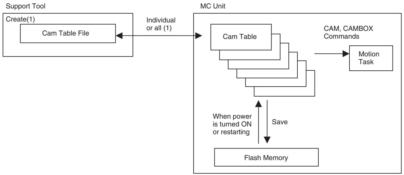
SECTION 5
Data Transfer and Storage
This section describes how to transfer data between the CPU Unit and the CJ1W-MCH71 and CS1W-MCH71 Motion Control Units and how data is stored.
5-1 Data Transfer and Storage 212
5-1-1 Data Transfer Overview 212
5-1-2 Data Storage Overview 213
5-1-3 Types of Data for Transfer and Storage 213
5-1-4 Transfer and Storage of Servo Parameters 215
5-2 IOWR Instruction to Transfer Data 221
5-2-1 Overview 221
5-2-2 IOWR: Intelligent I/O Write 222
5-2-3 Flags 223
5-2-4 Precautions When Using IOWR 223
5-2-5 IOWR Program Example 223
5-3 IORD Instruction to Transfer Data 228
5-3-1 Overview 228
5-3-2 IORD: Intelligent I/O Read 228
5-3-3 Flags 230
5-3-4 Precautions when Executing IORD Instruction 230
5-3-5 IORD Program Example 230
5-4 Saving Data 234
5-4-1 Flash Memory 234
5-4-2 Data Saving Procedure 235
5-4-3 Ladder Program Example of Saving the Data Transferred Using IOWR Instruction 235
5-1 Data Transfer and Storage
5-1-1 Data Transfer Overview
The following methods are available for transferring data between CPU and MC Units.
1,2,3... 1. Download or upload data from the Support Tool
Programs, system parameters, servo parameters, position data, Cam data created with the Support Tool, can be downloaded to or uploaded from the MC Unit.
The system parameters, servo parameters, and position data in the MC Unit can be uploaded to CX-Motion-MCH. Servo parameters can be transferred to the memory in the servo driver.
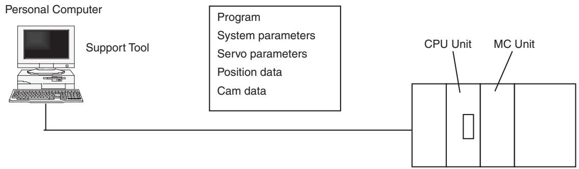
2. Read and write data in the MC Unit directly using IOWR/IORD instructions in the ladder program
The IOWR/IORD instructions can be used to read or write data while the CPU Unit is running.
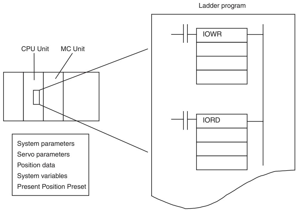
Note Make sure that parameters and data are appropriate to operate.
5-1-2 Data Storage Overview
Transferred data and parameters are written to the internal memory of the MC Unit where they will be used for operation, but they will be lost if the MC Unit is turned OFF or the MC Unit is restarted from the CPU Unit. The data must be saved in the flash memory using the bit area to keep the data in the MC Unit.
Refer to 5-4 Saving Data (page 234) for more details on storing data in flash memory.
Once data has been saved, it is stored in the flash memory of the MC Unit. The data will be available from the next time the MC Unit is turned ON or the MC Unit is restarted.
These data simply transferred without being saved will be lost when the MC Unit is turned OFF or the Unit is restarted.
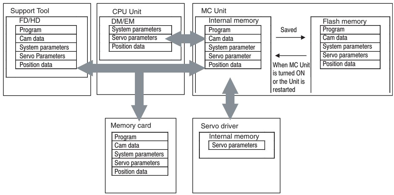
Note
(1) Data that has been saved in the flash memory will be automatically read to the internal memory when the MC Unit is turned ON or the Unit is restarted.
(2) Do not turn OFF the MC Unit or restart the Unit while data is being saved. Doing so may damage the flash memory in the MC Unit. It may take up to 30 seconds to save data.
(3) Data cannot be saved while data is being transferred or the Unit is busy.
(4) Flash memory has a limited service life. Data can be written up to 100,000 times.
5-1-3 Types of Data for Transfer and Storage
The following types of data can be transferred using CX-Motion-MCH, or directly by executing IOWR/IORD instructions.
Refer to SECTION 4 MC Unit Internal Data Configuration and Setting (page 55) for details on the data and addresses.
Yes: Possible No: Not possible Save: Saved in Flash Memory
| Data | Content | Data con-figuration | Read/Write/Save | ||||||
| Support Tool (See note 1.) | IOWR/IORD | ||||||||
| Read | Write | Save | Read | Write | Save | ||||
| Programs | Programs for MC Unit | - | Yes | Yes | Yes | No | No | No | |
| Cam data | Data for Electronic Cam | - | Yes | Yes | Yes | No | No | No | |
| Variables | |||||||||
| Position data | Data indicating positions | 2 words/position | Yes | Yes | Yes | Yes | Yes | See note 2. | |
| System variable | Status for MC Unit | 2 words/position | No | No | No | Yes | No | No | |
| Global general variable | These variables can be accessed from all tasks | - | No | No | No | No | No | No | |
| Input variable | Input status from CPU Unit, MECHATROLINK-II devices | - | No | No | No | No | No | No | |
| Output variable | Output from programs to CPU Unit or MECHA-TROLINK-II devices | - | See*3 | No | No | No | No | No | |
| Task variable | These variables can be used only in each task | - | No | No | No | No | No | No | |
| Present position preset | Sets present position pre-set value for each axis | 2 words/position | No | No | No | No | Yes | No | |
| System parameters | |||||||||
| Unit | System parameters are: Unit parameters, Task parameters, Axis-parameters, Number of axes to use, number of tasks, feed rate, operation range, and etc. data for the system is stored. | 2 words/position | Yes | Yes | Yes | Yes | Yes | See note 2. | |
| Motion task | |||||||||
| Axis: allocations | |||||||||
| Axis: speed | |||||||||
| Axis: position | |||||||||
| Axis: origin | |||||||||
| Axis: machine | |||||||||
| Reserved | |||||||||
| Axis specification for servo parameter (See note 4.) | Specify axis to be accessed | 2 words/position | No | No | No | Yes | Yes | No | |
| Servo parameter | Parameters for servo driver | 2 words/position | Yes | Yes | Yes | Yes | Yes | See note 2. | |
Note
(1) From CX-Motion-MCH, all the data are read or written at the same time. The data cannot be read or written partially.
(2) Turn ON either the bit "Parameter Save" or "Position Data Save" in PC Interface Area to save in Flash Memory.
(3) Alarm codes can be read.
(4) To read/write servo parameters, specify the axis in advance.
(5) Parameters changed with MC Unit programs cannot be saved.
5-1-4 Transfer and Storage of Servo Parameters
The following table shows the methods for transferring and saving servo parameters.
| No. | Trigger | Operation | Object |
| 1 | the Support Tool | Read | RAM of the servo driver |
| 2 | RAM of the MC Unit | ||
| 3 | IORD instruction of the CPU Unit | RAM of the servo driver | |
| 4 | the Support Tool | Write | RAMs of the servo driver and the MC Unit |
| 5 | IOWR instruction of the CPU Unit | RAMs of the servo driver and the MC Unit | |
| 6 | PARAM command of the MC Unit | RAM of the servo driver | |
| 7 | the Support Tool | Save | EEPROM of the servo driver and Flash ROM of the MC Unit |
| 8 | The “Parameter Save” bit | EEPROM of the servo driver and Flash ROM of the MC Unit |
Overview of Operation and Data
1,2,3... 1. Reading from Servo Driver Using Support Tool
Servo parameters are read from the servo driver. The servo parameters in the MC Unit will not be affected.
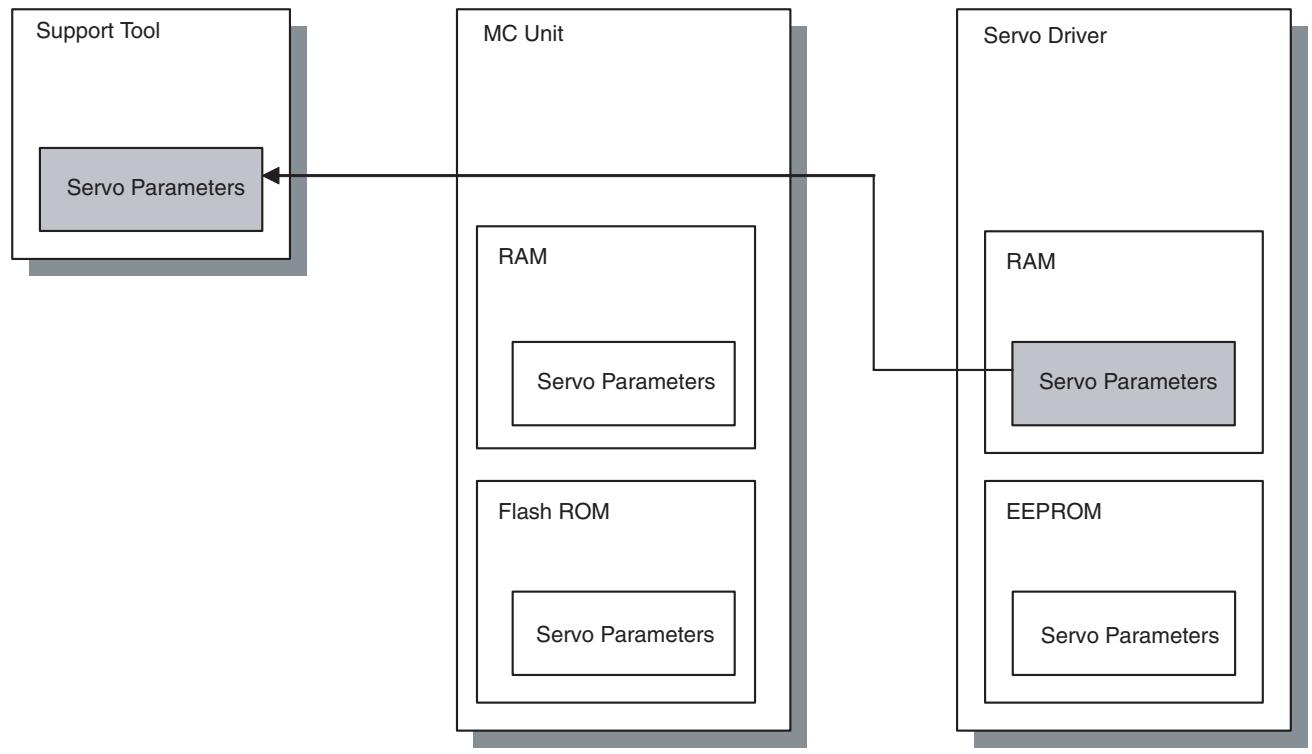
2. Reading from MC Unit Using FINS Commands
The servo parameters are read from the RAM of the MC Unit.
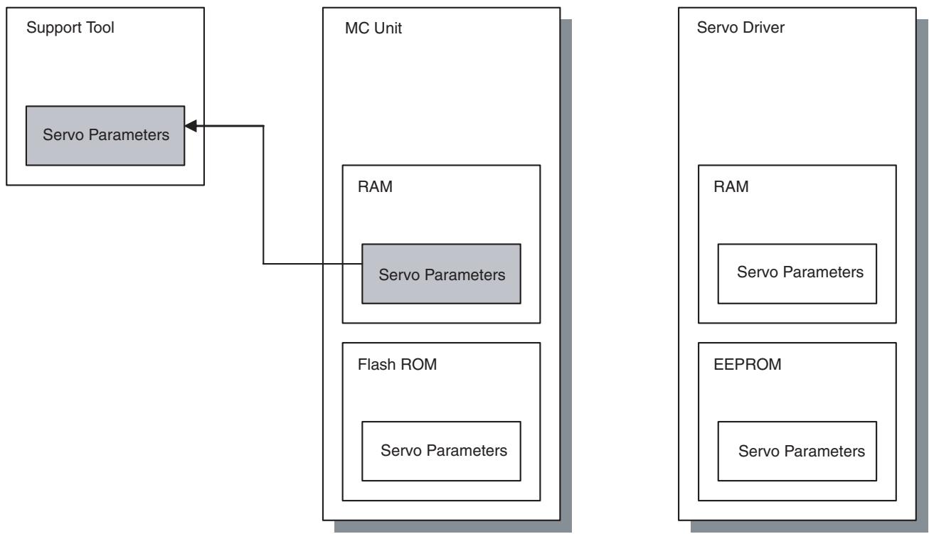
3. Reading by IORD Instruction
Servo parameters are read from the servo driver. The servo parameters in the MC Unit will not be affected.
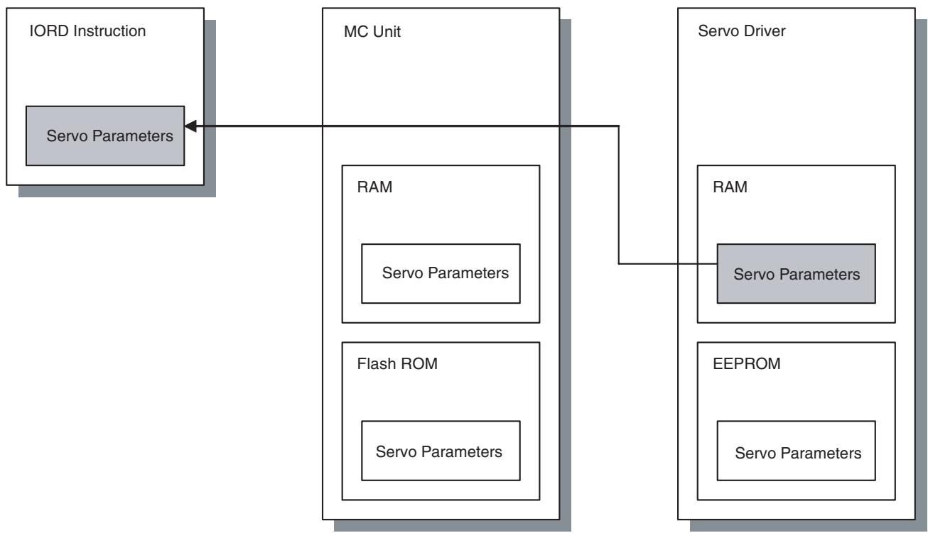
4. Writing by Support Tool
- The servo parameters will be written in both the MC Unit and servo driver.
- The written servo parameters will be the object of Flash ROM save.
- Writing is executed regardless of whether it is immediately enabled or enabled when the power is turned ON.
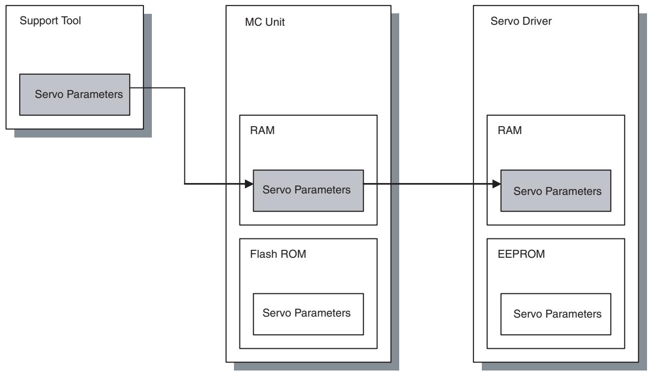
5. Writing by IOWR Instruction
- The servo parameters are written in the RAMs of both the MC Unit and the servo driver.
- Writing is executed regardless of whether it is immediately enabled or enabled when the power is turned ON.
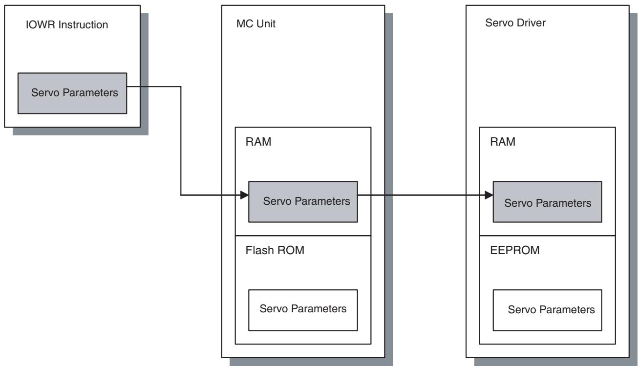
6. Writing by PARAM Command
- This is just a temporary writing, so it will not be the object of Flash ROM save.
- Only the servo parameters in the RAM of the servo driver will be overwritten.
- Writing is executed regardless of whether it is immediately enabled or enabled when the power is turned ON.

- Contents of EEPROM and RAM in the servo driver will be identical with each other. (They are not identical while change is in process, however, they will be identical after writing.)
-
When a servo parameter that is not immediately enabled is changed, the parameter that was written would be different from the one having been read.
-
Saving by Support Tool
8. Saving by Allocated IF Area
Saves the servo parameters of the MC Unit to servo driver's EEPROM and MC Unit's Flash ROM.
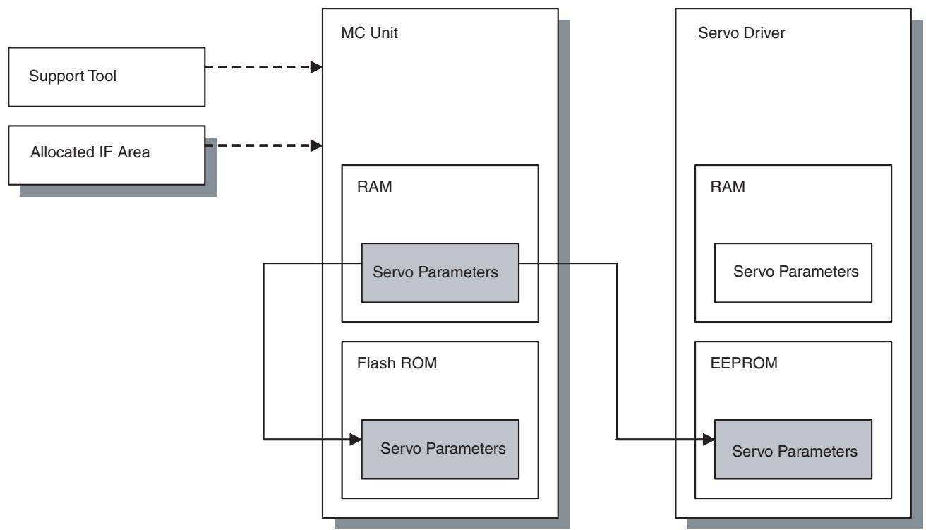
Precautions when
Replacing a Servo Driver
Servo parameters stored in the servo driver are used for actual operations.
For that reason, make sure to read the servo parameters before the replacement, and restore them into the newly replaced servo driver.
5-2 IOWR Instruction to Transfer Data
5-2-1 Overview
Position data, system parameters, and servo parameters can be written to the MC Unit by executing the CPU Unit's IOWR instruction. Present position preset is also executed by IOWR instruction.
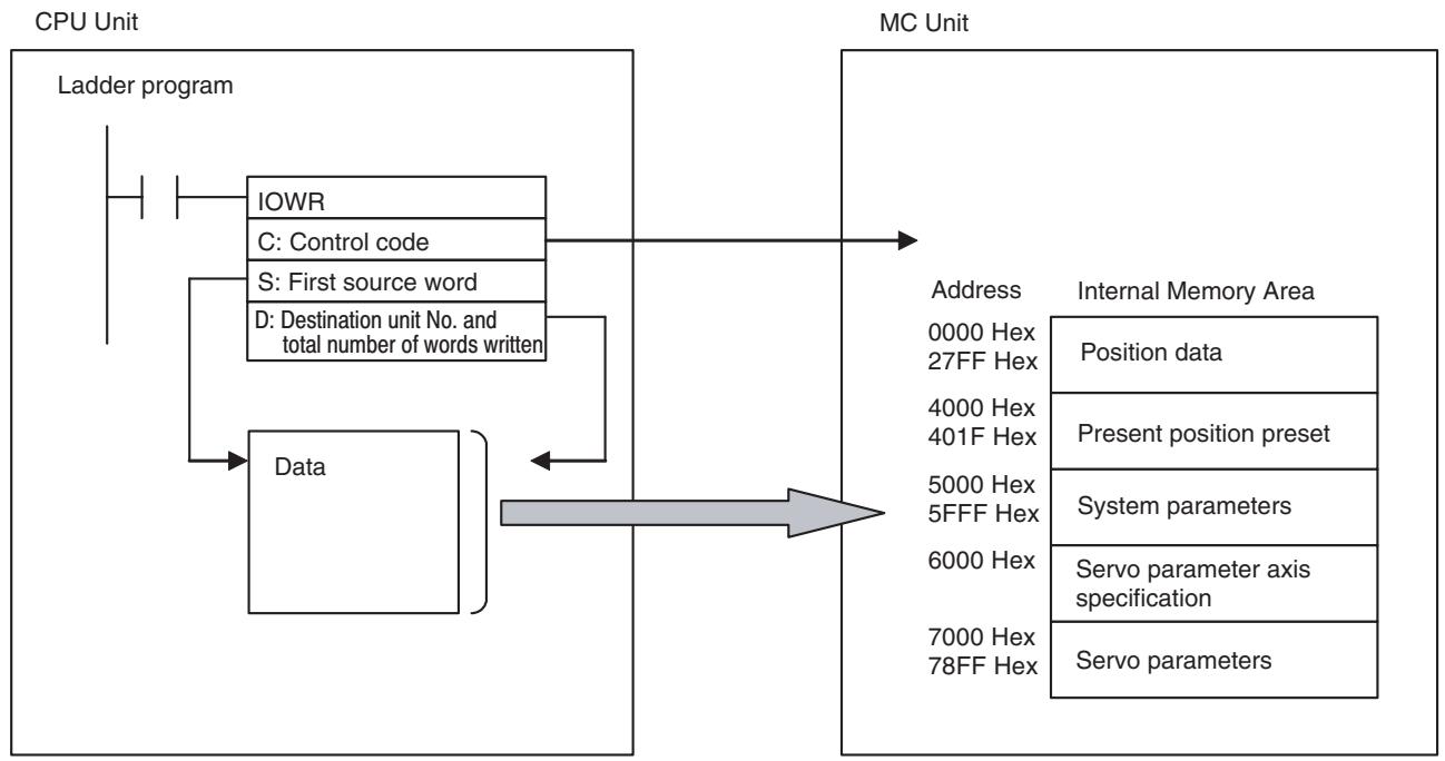
Procedure for Writing Data
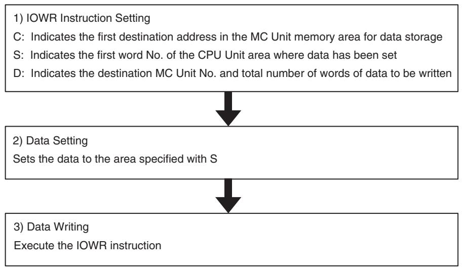
5-2-2 IOWR: Intelligent I/O Write
| IOWR | @IOWR |
| C | C |
| S | S |
| W | W |
| Operand | Description | |
| C: Control code | MC Unit address (Hex) | |
| Specifies the first address in the MC Unit where data will be written (in hexadecimal). | ||
| S: First source word | First source word | |
| Specifies the first word in the CPU Unit from which data is to be transferred. Refer to CS/CJ-series manual for each word detail. | ||
| Area | Value used for specification | |
| C/O Area (I/O bits, etc.) | 0000-6143 | |
| Work Area | W000-511 | |
| Holding Bit area | H000-511 | |
| Auxiliary area | A000-959 | |
| Timer Area | T0000-4095 | |
| Counter Area | C0000-4095 | |
| DM Area | D00000-32767 | |
| EM Area | E00000-32767 | |
| DM Area with bank designation | En_00000-32767 (n = 0 to C) | |
| Indirect DM/EM (BIN) | @D00000-32767 @E00000-32767 @En_00000-32767 (n = 0 to C) | |
| Indirect DM/EM (BCD) | *D00000-32767 *E00000-32767 *En_00000-32767 (n = 0 to C) | |
| D: Destination unit number and total number of words written | Total number of words transferred (Hex) | Destination unit number (Hex) |
| Total number of words transferred (Hex) Destination unit number (Hex) | ||
| Specifies the total number of transferred words (No. of transferred words) and unit number of data transfer destination (destination unit No.). | ||
| Total number of words to transfer: 0002 to 0008 Hex (8 words) | ||
| • System parameter: 0002 Hex | ||
| • Servo parameter axis specification:0002 Hex | ||
| • Servo parameter: 0002 Hex | ||
| • Position data: 0002, 0004, 0006, 0008 Hex (Up to 4 synchronous writing is possible) | ||
| • Present position preset: 0002 Hex | ||
| Destination unit number | ||
| • 8000-800F Hex | ||
| Example) | ||
| Transferring three of position data (6 words) to unit number 3: #00068003 (total number of words transferred: 0006 [6 words], unit No.8003 [No.3]) | ||
5-2-3 Flags
| Name | Symbol | ON | OFF |
| Error Flag | ER | ·The total No. of words transferred in D is not between 0000 and 0008 Hex. ·The unit No. in D is not between 8000 and 800F Hex. ·The specified CPU Bus Unit does not support the IOWR instruction. ·The specified CPU Bus Unit has a setting error or Unit error. ·An error has occurred. ·Position data to be transferred was not in the specified format or not within acceptable range. ·The specified address does not exist in the MC Unit. ·Data in the specified MC Unit address is read-only data. ·The specified No. of position data words to be transferred was not a multiple of two. ·The No. of system parameter words to be transferred was not two. ·The value of the MC Unit address plus the number of words transferred divided by 2 exceeded 27FFHex (upper position data limit 10240). ·More than 8 words were specified for position data transfer. | ·The conditions other than the ones described on the left |
| Equals Flag | = | ·The IOWR was completed successfully. | ·The IOWR was not completed normally. ·A previous transfer has not been completed. |
5-2-4 Precautions When Using IOWR
When transferring data by IOWR instruction, be sure to transfer the data with the total number of transferred words (2 to 8 words). Do not start or end transferring in the middle of the data. Doing so will turn ON the ER flag.
When performing continuous transfer of data by IOWR instruction, make sure that the Equals Flag is ON before executing the next IOWR instruction. For details, refer to Ladder Program Example on page 226.
5-2-5 IOWR Program Example
This section provides a detailed example of data transfer when the MC Unit is mounted on a CJ-series PLC and the unit number is set to zero. In this example, it is assumed that operands in the IOWR and the transferred data are correct.
When debugging, create a ladder program that refers to the ER flag or the [Alarm] bit (n+12 words bit 00).
Example 1) Transfer four of position data to the data addresses PL0456 Hex to PL0459 Hex in the MC Unit.
Position data to be transferred Destination addresses
34567890 PL0456
12345678 PL0457
-38765432 PL0458
123456 PL0459
Ladder Program Example
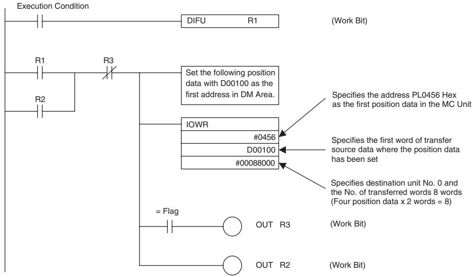
Data Settings [DM]
![OMRON CJ1W-MCH71 - Data Settings [DM] - 1](/content/2024/12/168263/images/43ae60eda9469ca355da42aca316a9567097b4d55b06bf9c72a98e8c9000f06e.jpg)
Example 2) Change the manual feed acceleration time to 500 [ms]
Ladder Program Example
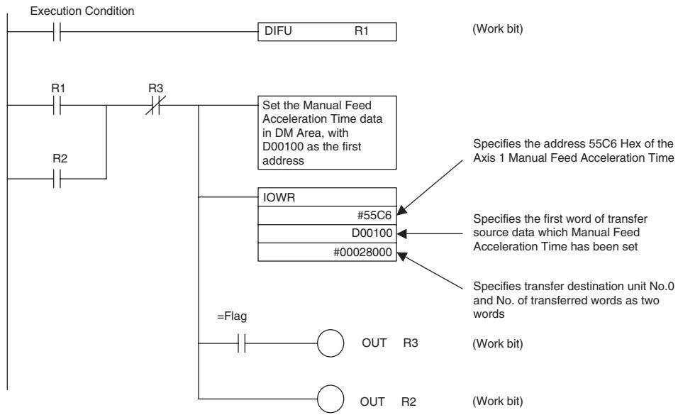
Data Settings [DM]
![OMRON CJ1W-MCH71 - Data Settings [DM] - 1](/content/2024/12/168263/images/1273045a89ee5da49e7c61a639fc964670a772ceeb756e0e5bc700c2e8b1104e.jpg)
Example 3) Write the servo parameters using IOWR instruction
- To write the servo parameters, the servo parameter axis has to be specified in advance. Write the axis No. in 6000h of IORD/IOWR control code (address in the MC Unit).
- The setting value for the servo parameter axis specification is to be [Axis No. - 1] as shown below:
| Axis No. | Setting value for specifying axis |
| 1 | 0h |
| 2 | 1h |
| 3 | 2h |
| : | : |
| 30 | 1Dh |
| 31 | 1Eh |
| 32 | 1Fh |
- IORD/IOWR control addresses (address in MC Unit) corresponding to the parameter Nos. of the servo driver (Pn000 to Pn8FF) are as shown below:
| Parameter No. | Address in MC Unit |
| Pn000 | 7000h |
| Pn001 | 7001h |
| Pn002 | 7002h |
| : | : |
| Pn8FD | 78FDh |
| Pn8FE | 78FEh |
| Pn8FF | 78FFh |
Procedure
1,2,3... 1. Set the data in the data area of the transfer source.
- Specify the servo parameter axis.
- Transfer the parameter setting values for the number needed.
Ladder Program Example
The parameter axis for the servo driver is set to the values in D0100 and D0101. 2-word data in D0110 and D0111 are written in the servo driver parameter No. Pn000.

Timing Chart in Executing IOWR Instruction (Address Specification)
The following describes the timing and processing when IOWR instruction is executed.
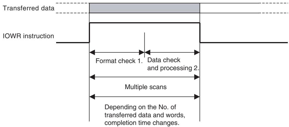
1,2,3...
- At first, on the CPU Unit, check if specifications of IOWR instruction's operands are correct.
(Format check) If they are not correct, the ER Flag will turn ON to interrupt the IOWR instruction.
- And then, on the MC Unit, check if the data in operands is applicable for processing in the MC Unit. (Data check)
If the data is applicable for processing, the = Flag will turn ON.
If the data is not applicable for processing, the = Flag will not turn ON and the instruction will be interrupted.
Transfer should be completed by the rise of the = Flag.
5-3 IORD Instruction to Transfer Data
5-3-1 Overview
Position data, system variables, system parameters, and servo parameters can be read by executing the CPU Unit's IORD instruction.
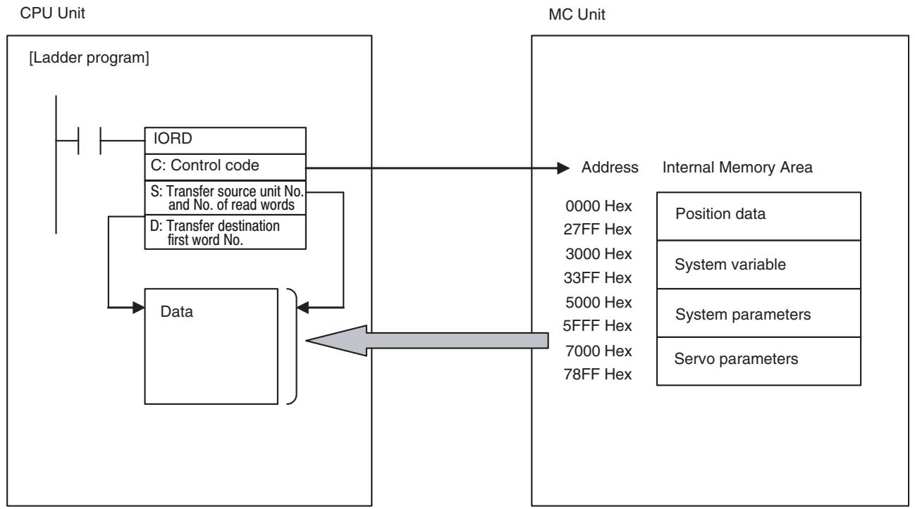
Note: To read servo parameters, it is necessary to specify the servo parameter axis in advance.
Procedure for Reading Data
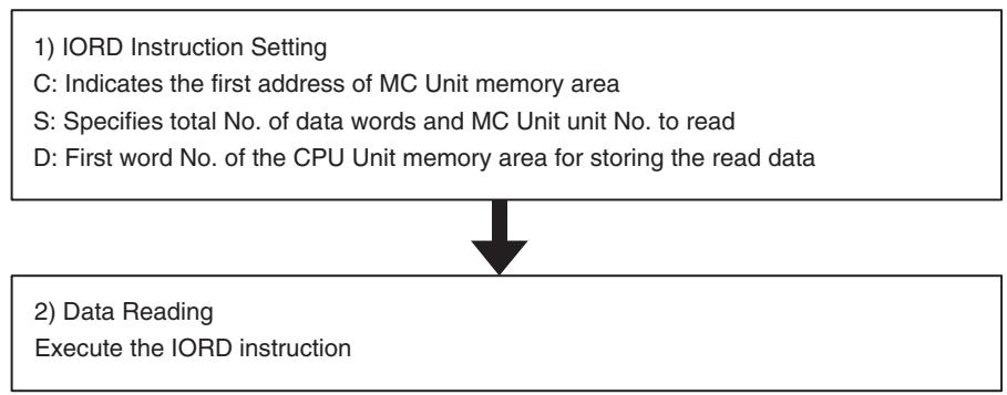
5-3-2 IORD: Intelligent I/O Read
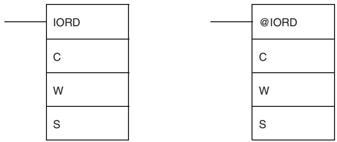
| Operand | Description | |
| C: Control code | MC Unit address (Hex) | |
| Specifies the first address of the data in the MC Unit to be read. | ||
| D: No. of transferred words/Transfer source unit No. | W+1 WNo. of transferred words (Hex) Transfer source unit No. (Hex) | |
| Specifies the total No. of transferred words (No. of transferred words) and unit number of data transfer destination (destination unit No.).No. of transferred words: 0002 to 0008 Hex (8 words)· System parameter: 0002 Hex· Servo parameter axis specification:0002 Hex· Servo parameter: 0002 Hex· Position data: 0002, 0004, 0006, 0008 Hex (Up to 4 position data can be read simultaneously)· System variables: 0002, 0004, 0006, 0008 Hex (Up to 4 position data can be read simultaneously)Transfer source unit No.:· 8000-800F HexEx) When reading 3 position data (6 words) from the unit No.3, set as the operand as shown below:#00068003 (No. of transferred words: 0006 [6 words], unit No. 8003 [No.3]) | ||
| S: Transfer destination first word | Transfer destination first word No. | |
| Transfer destination first word No.Specifies the first word of the CPU Unit in which the data to be transferred has been set.Refer to the CJ-series manuals for more details. | ||
| Area | Value used for specification | |
| CIO Area | 0000-6143 | |
| Work Area | W000-511 | |
| Holding Bit area | H000-511 | |
| Auxiliary area | A000-959 | |
| Timer Area | T0000-4095 | |
| Counter Area | C0000-4095 | |
| DM Area | D00000-32767 | |
| EM Area | E00000-32767 | |
| DM Area with bank designation | En_00000-32767 (n = 0 to C) | |
| Indirect DM/EM (BIN) | @D00000-32767@E00000-32767@En_00000-32767 (n = 0 to C) | |
| Indirect DM/EM (BCD) | *D00000-32767*E00000-32767*En_00000-32767 (n = 0 to C) | |
5-3-3 Flags
| Name | Symbol | ON | OFF |
| Error Flag | ER | ·The No. of transferred words in D is not between 0000 and 0008 Hex. ·The unit number data in D is not between 8000 and 800F Hex. ·The specified CPU Bus Unit does not support the IORD instruction. ·The specified Unit has a setting error or unit error. ·The read position data was not in the specified format or not within acceptable range. ·The specified MC Unit address does not exist. ·The specified No. of position data words transferred was not a multiple of two. ·The specified No. of system parameter words transferred was not a multiple of two. ·The value of the MC Unit address plus the number of transferred words divided by 2 exceeded 27FF Hex (upper position data limit 10240). ·More than 8 words were specified for position data transfer. | ·The conditions other than the ones described on the left. |
| Equals Flag | = | ·The IORD instruction was completed successfully. | ·The IORD instruction was not completed normally. ·A previous transfer has not been completed. |
5-3-4 Precautions when Executing IORD Instruction
When transferring the data by IORD instruction, make sure to transfer the data with the total number of transferred words (2 to 8 words). Do not start or end transferring the data in the middle of the data. Doing so will turn ON the ER flag.
When performing continuous transfer of data by IORD instruction, make sure that the Equals Flag is ON before executing the next IORD instruction. For details, refer to Ladder Program Example on page 233.
5-3-5 IORD Program Example
This section provides a detailed example of data transfer when the MC Unit is mounted on a CJ-series PLC and the unit number is set to zero. In this example, it is assumed that operands in the IORD and the transferred data are correct.
When debugging, create a ladder program that refers to the ER flag or the [Alarm] bit (n+12 words bit 00).
Example 1) Read four position data (PL0456 to PL0459 Hex) in the MC Unit to the D00100 toD00107.
Position data to be read Destination address
PL0456 4567890 → D00100 to D00101
PL0457 12345678 → D00102 to D00103
PL0458 -38765432 → D00104 to D00105
PL0459 123456 → D00106 to D00107
Ladder Program Example
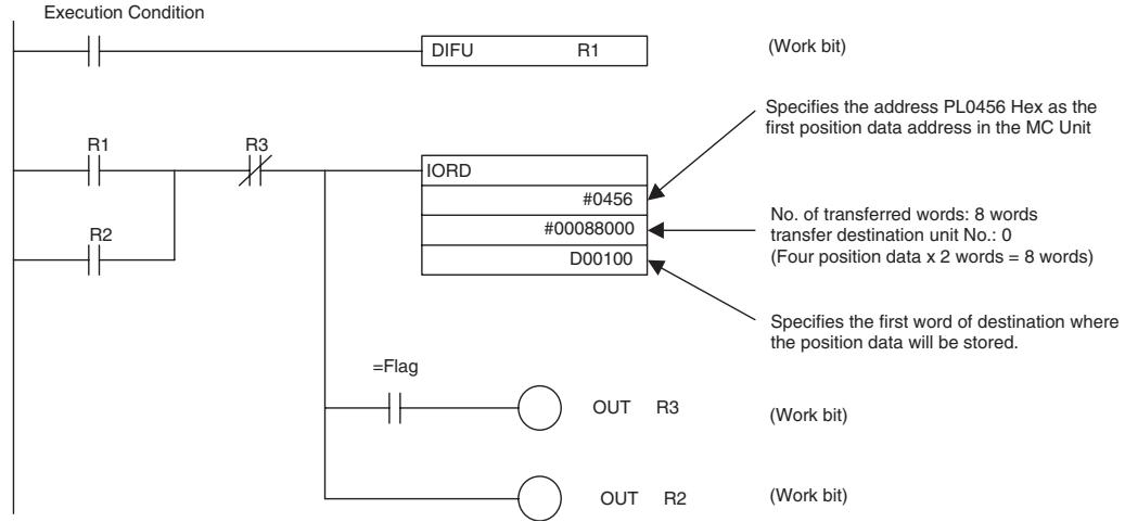
Data after Reading [DM]
![OMRON CJ1W-MCH71 - Data after Reading [DM] - 1](/content/2024/12/168263/images/e4f2f3ee71245d7c13c577716b2b4c3083047198d5ac6a53f4b92f7ff8d841bd.jpg)
Example 2) Read the Axis 1 Manual Feed Acceleration Time (500[ms]) to D00100 to D00101.
Ladder Program Example
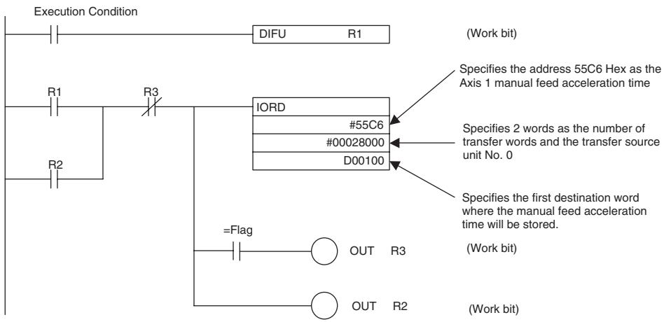
Data after Reading [DM]
![OMRON CJ1W-MCH71 - Data after Reading [DM] - 1](/content/2024/12/168263/images/e60885fdb333bb771ca99c5f07cfa66c9fb3b1a5b7a6d17e614c6d1e1d81593d.jpg)
Example 3) Read the servo parameters using IORD instruction
-
To read the servo parameters, the servo parameter axis has to be specified for the IOWR instruction in advance. Write the axis No. in 6000h of IORD/IOWR control code (address in the MC Unit).
-
Setting values for specifying the servo parameter axis are to be [Axis No. -1] as shown below:
| Axis No. | Setting value for axis specification |
| 1 | 0h |
| 2 | 1h |
| 3 | 2h |
| : | : |
| 30 | 1Dh |
| 31 | 1Eh |
| 32 | 1Fh |
- IORD/IOWR control addresses (addresses in the MC Unit) corresponding to the parameter Nos. (Pn000 to Pn8FF) of the servo driver are as shown below:
| Parameter No. | Address in MC Unit |
| Pn000 | 7000h |
| Pn001 | 7001h |
| Pn002 | 7002h |
| : | : |
| Pn8FD | 78FDh |
| Pn8FE | 78FEh |
| Pn8FF | 78FFh |
Procedure
1,2,3... 1. Set the data in the data area of the transfer source.
- Specify the servo parameter axis.
- Read the parameter setting values for the number needed.
Ladder Program Example
The parameter axis of the servo driver is set to the values in D0100 and D0101. The value in the parameter Pn000 of the servo driver is read and stored in D0110 and D0111.
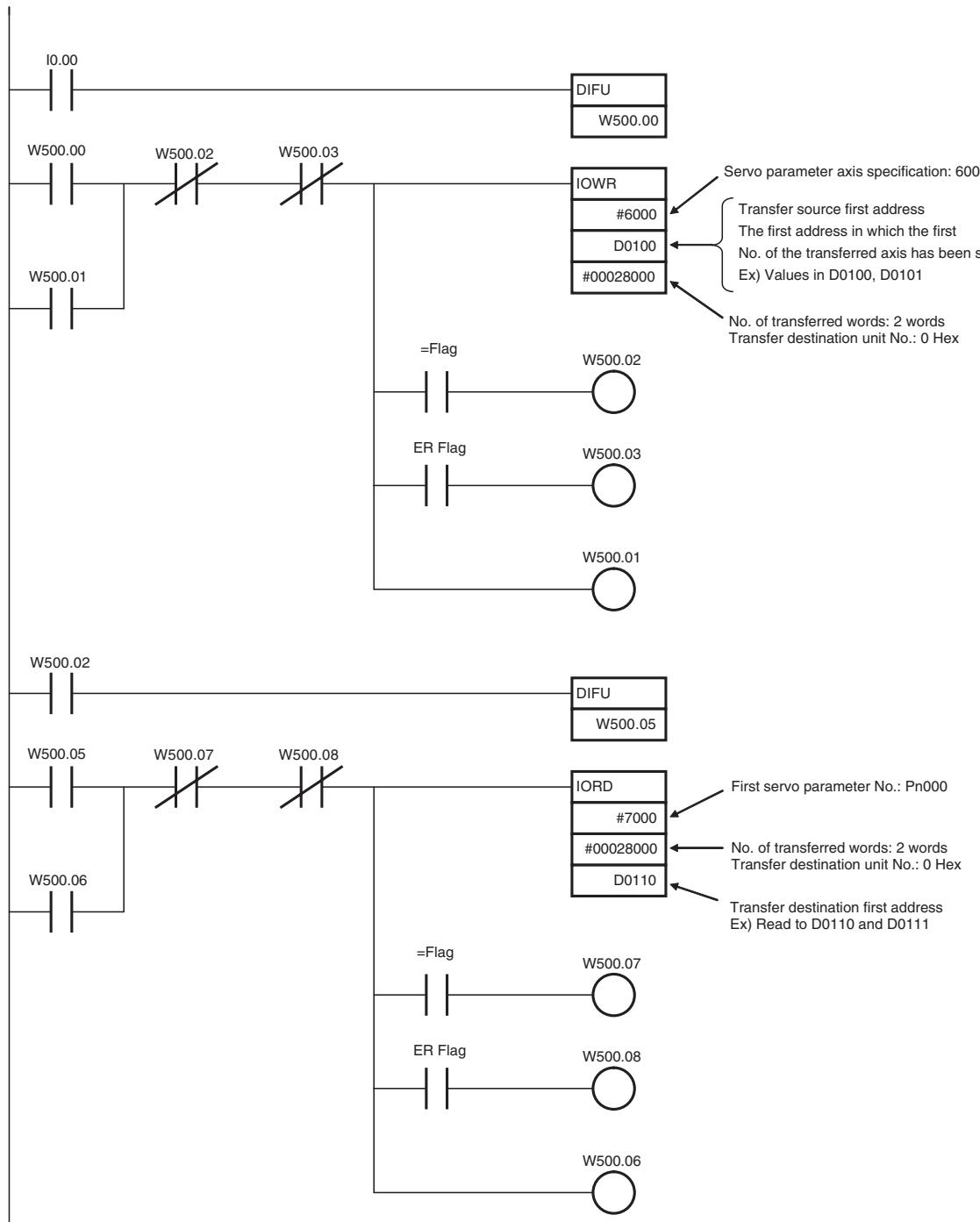
Timing Chart in Executing IORD Instruction (Address Specification)
The following describes the timing and processing when executing IORD instruction.
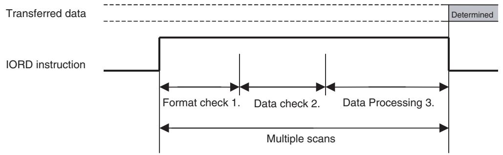
1,2,3...
- At first, on the CPU Unit, check if IORD instruction's operands specifications are correct. (Format check) If they are not correct, the ER Flag turns ON to interrupt the IORD instruction.
- And then, on the MC Unit, check the data specified with the operands is applicable for processing in the MC Unit. (Data check) If the data is not applicable for processing, the = Flag will not turn ON and the instruction will be interrupted.
- Finally, transfer the specified data from the MC Unit to the CPU Unit. When transfer is completed, the = Flag will be turned ON.
5-4 Saving Data
Data transferred to the MC Unit will be erased either when the power is turned OFF or when the MC Unit is restarted from the CPU Unit. To preserve the data that has been transferred, it must be saved to the Flash Memory in the MC Unit. Once it is saved in the Flash Memory, it can be read and used from the next time the power is turned ON or the Unit is restarted. When the data is saved, all the data including parameters existing at that point are saved.
Note
(1) Do not turn OFF the power or restart the CPU while data is being saved. It may cause a failure of the Flash Memory in the MC Unit, or cause the MC Unit to operate abnormally.
(2) Flash memory has a limited service life. Data can be written up to 100,000 times.
(3) Do not save any data during program operations or when motors are operating. Unexpected operation may result.
(4) It may take a maximum of 30 seconds to save the data into the Flash Memory.
5-4-1 Flash Memory
The data listed below can be saved in the Flash Memory.
- Programs
- Cam data
- System parameters
- Servo parameters
- Position data
5-4-2 Data Saving Procedure
The PC Interface Area (bit area) is used to save the transferred data in MC Unit.
Procedure
Saving parameters: n+0 word Bit 01
Saving position data: n+0 word Bit 02
Status
Flash save completed: n+15 word Bit 02
Refer to SECTION 7 PC Interface Area (page 373) for details.
5-4-3 Ladder Program Example of Saving the Data Transferred Using IOWR Instruction
In this example, Position data is transferred to the position data address in the MC Unit using the IOWR instruction. The transferred position data is then saved in the Flash Memory.
Program Example:
Transferring One Data Item
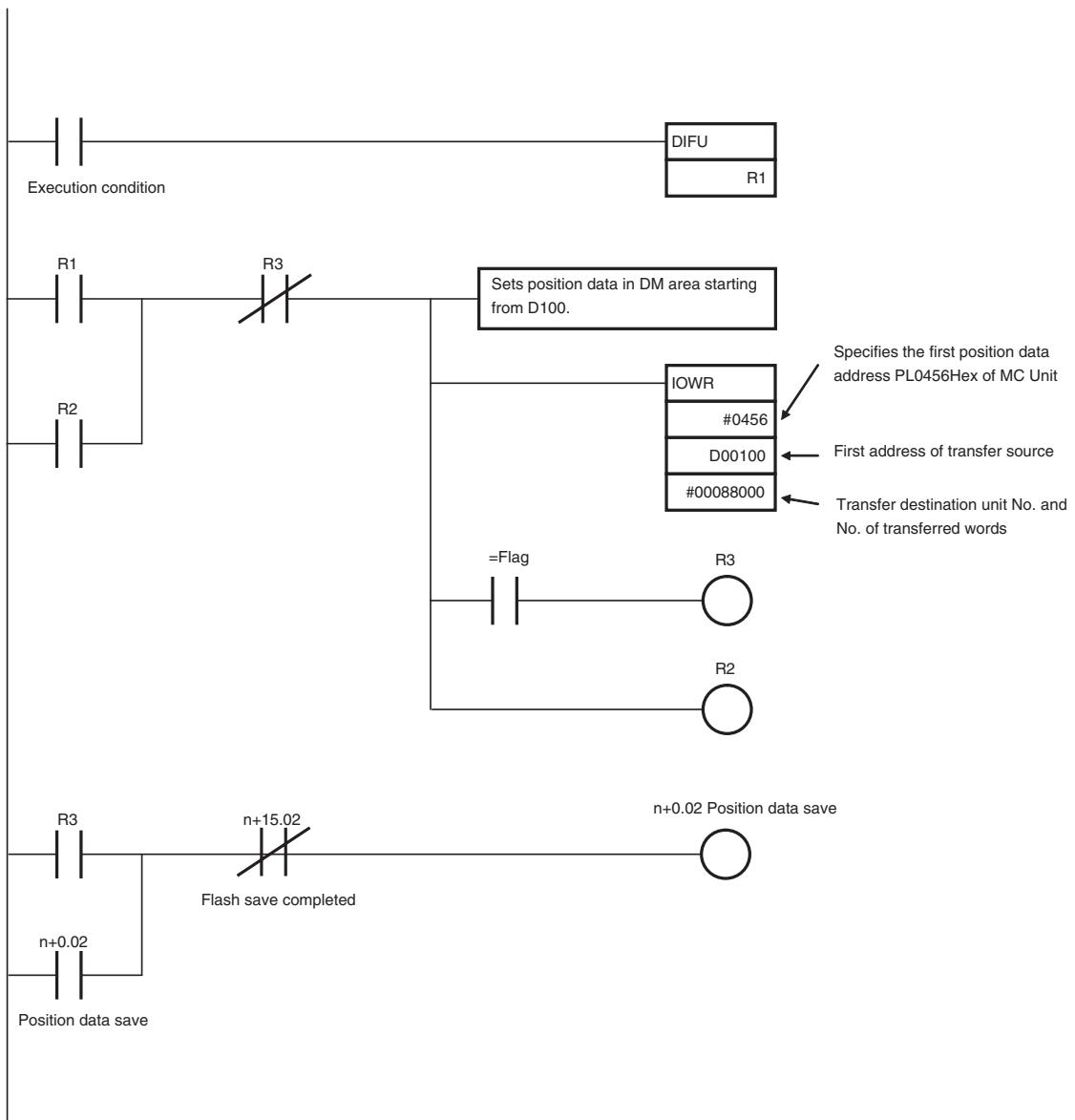
Program Example:
Transferring More Than
One Data Item
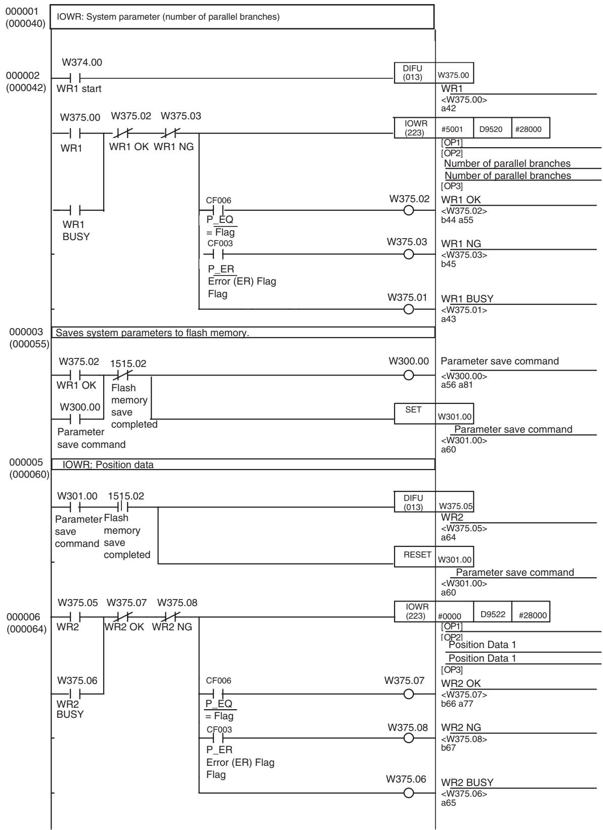
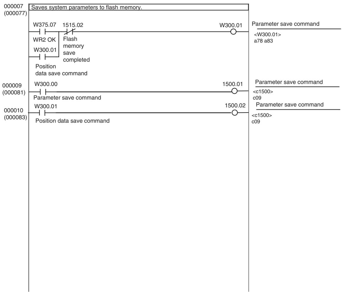
SECTION 6 Programming
This section describes how to program CJ1W-MCH71 and CS1W-MCH71 Motion Control Unit operation, including the program configuration and the specific commands used in programming.
6-1 Basic Information 240
6-1-1 Program and Task Configuration 240
6-1-2 Task Execution Format 241
6-1-3 Advancement of the Motion Program 242
6-1-4 Program System 248
6-1-5 Axis Movement Operation 248
6-1-6 Synchronous Command 271
6-1-7 Modal Data 275
6-1-8 Nesting 276
6-1-9 Unit for Time 276
6-1-10 Conditional Expression. 276
6-1-11 Arithmetic Command 277
6-1-12 Data Used for Operand. 281
6-1-13 Virtual Axis. 282
6-1-14 I/O Axis 283
6-1-15 Parameters having Influence on Axis Operation 284
6-1-16 Coordinate System 285
6-2 Command Overview 286
6-2-1 Command List 286
6-2-2 Command Format. 290
6-2-3 Command List (Operand List) 295
6-2-4 Program Number and Axis Declaration 297
6-2-5 Default Mode and Coordinate System 297
6-3 Command Details 298
6-3-1 Expression in This Section 298
6-3-2 Axis Movement. 298
6-3-3 Command for Axis Operations/Operation Cancel 316
6-3-4 Setting Command 338
6-3-5 Control Command 347
6-3-6 Simple Arithmetic Operation 361
6-3-7 Logic Operation 363
6-3-8 Function 365
6-3-9 Bit Operation 367
6-3-10 Data Operation 368
6-1 Basic Information
6-1-1 Program and Task Configuration
The programs are written by the user to control the application using the MC Unit. The tasks are units for work to execute the programs. The MC Unit can have up to 8 motion tasks for axis control.
The motion tasks are primarily used to execute operations related to axis movement and through declaring axes to be used by the motion program, a motion task can have 1 to 32 axes.
Note that the same one axis cannot be shared among several motion tasks simultaneously. To use a single axis for multiple tasks, exit the program used for the relevant axis. After exiting the program, run the other programs to be used by the relevant axis.
There is no need to use the motion tasks in the applications that use only the allocation bit area of the CPU Unit to operate, i.e. applications that do not require the motion program.
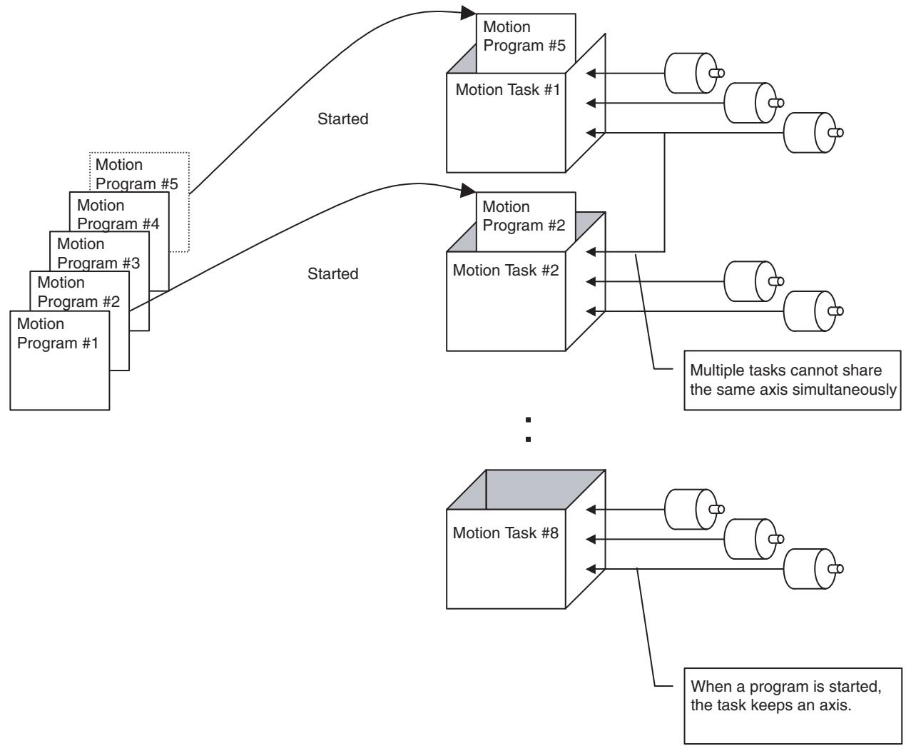
Exchanging Data Between Tasks
It is possible to exchange data between tasks through the global general variable. Since exchanging data between motion tasks is also possible through the global general variable, a simplified interlock can be provided.
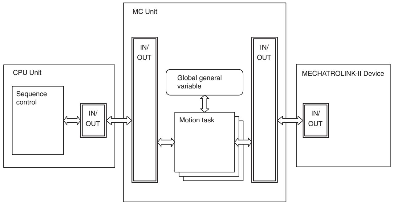
Programming Language
Motion tasks are described with the common language.
6-1-2 Task Execution Format
Motion tasks are executed stepwise, and a maximum of 8 tasks can be executed individually in parallel.
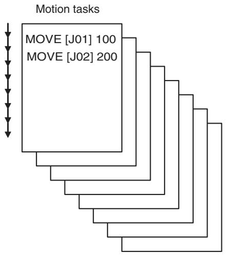
The Unit Cycle is either the same or twice the MECHATROLINK-II (MLK) communications cycle.
| Communications cycle (ms) | Unit Cycle (ms) |
| 1 | 1 or 2 |
| 2 | 2 or 4 |
| 3 | 3 or 6 |
| 4 | 4 or 8 |
For details, refer to 1-7 Performance on page 21.
All running motion tasks are executed in task number order in each Unit Cycle. The number of commands that can be executed in each Unit Cycle depends on the number of parallel branches and the type of command (single execution or multiple execution). For details, refer to 6-1-3 Advancement of the Motion Program on page 242.
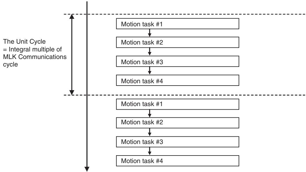
6-1-3 Advancement of the Motion Program
This section describes how execution of respective blocks advances (stepping or steps for processing). Each program is executed by a motion task separately, so the stepping of respective blocks can be considered independent as well.
Basic Concept
1,2,3... 1. The maximum number of motion commands that can be executed in a motion task in one Unit cycle (1, 2, 3, 4, 6, or 8 ms) can be specified in MC Units.
The maximum number of commands is specified using the following parameters.
Unit Versions Earlier Than 3.0:
System parameter P00002 (Number of parallel branches) (Default: 4)
With the default, a maximum of four commands can be executed in a single motion task.
When two tasks are used, a maximum of eight commands (2 tasks x 4 commands = 8) can be executed in a single Unit cycle.
Unit version 3.0 or later:
- When system parameter P00004 (Unit function selection) bit 11 is 0 (default)
The number is specified using system parameter P00002 (Number of parallel branches). (Default: 4)
With the default, a maximum of four commands can be executed in a single motion task.
When two tasks are used, a maximum of eight commands (2 tasks × 4 commands = 8 ) can be executed in a single Unit cycle.
- When system parameter P00004 (Unit function selection) bit 12 is 1
The number is specified using motion task parameter P00M21 (Number of parallel branches per task). (Default: 0)
It is specified individually for each task.
An upper limit can be set for the commands executed for each task, such as four commands for task 1 and six commands for task 2 when two tasks are used
As shown in 1-7 Performance, the Unit cycle time depends on the number of commands executed, so this is used when it is desirable to shorten the Unit cycle or to speed up commands related to operations (arithmetic, logic, etc.) in the same cycle.
- The maximum number of branches when using the PARALLEL command is determined by parameter P00002 (Number of parallel branches) described above, or by P00M21 (Number of parallel branches per task).
The parameter sets the upper limit on the number of commands that can be executed at one time, so this value restricts the maximum number of parallel branches as well.
When the number of parallel branches written in a motion program is smaller than the value in P00002, the value in P00002 is divided by the actual number of parallel branches to calculate the number of commands that can be executed simultaneously in the branches.
If the number of parallel branches written in a motion program is greater, the alarm [200D: Rotation specification error] will occur during execution.
-
The commands used in motion tasks can be classified into two groups: [Single execution command] and [Multiple execution command].
-
Single Execution Command
In a motion task, two single execution commands cannot be executed simultaneously in one Unit Cycle. Commands related to axis movements, etc. that take time to finish the specified processing are usually of this type. However, it is possible to execute these commands along with a multiple execution command or to execute then in another branch during parallel branch execution.
Example: MOVE [J01] 1000; Executes positioning of axis 1 to 1000. #MW10000 = 1; This command is executed when axis 1 starts moving without waiting for positioning to be completed.
Use the NOPS command shown below to wait for positioning to be completed before executing the next command.
Example: MOVE [J01] 1000; Executes positioning of axis 1 to 1000. NOPS; Waits for axis 1 positioning to be completed. #MW10000 = 1; Executes this command only after axis 1 positioning has been completed.
- Multiple Execution Command
In a motion task, two or more multiple execution commands can be executed simultaneously in one Unit Cycle. A command of this type can be executed along with a single execution command or other multiple execution commands. Commands related to operations (arithmetic, logic, etc.) are usually of this type.
In the respective tables in this section, the word 'SINGLE' is used to indicate the [Single execution command], and 'MULTI' to indicate the [Multiple execution command].
Refer to the 6-2-1 Command List (page 286) for the type of each command.
-
Multiple execution commands are executed under the following conditions:
-
When there are no commands being executed.
- When a single execution command, which has a lower block number than that of the multiple execution command, is being executed. (A multiple execution command is not executed before any earlier single command not executed yet.)
Stepping in the Stop Mode
In the stop mode, the motion program advances following the 'Basic Concept' in the previous page.
Nevertheless, in the 'Single Block Operation Mode', regardless of SINGLE/MULTI, one block is executed at a time.
Operation image:
It takes three cycles to execute one single execution command and the maximum number of simultaneous executions is set to four. No parallel branching.
| No. | Command | Cycle | Comments | ||||||||
| 1 | 2 | 3 | 4 | 5 | 6 | 7 | 8 | 9 | |||
| 1 | SINGLE | ■ | ■ | ■ | SINGLE execution | ||||||
| 2 | SINGLE | ■ | ■ | ■ | This is SINGLE, so execution begins after command No.1 is completed. | ||||||
| 3 | MULTI | ■ | This is MULTI, so it is executed along with command No.2. | ||||||||
| 4 | MULTI | ■ | This is MULTI, so it is executed along with command No.2. | ||||||||
| 5 | MULTI | ■ | This is MULTI, so it is executed along with command No.2. (The 4th command executed simultaneously) | ||||||||
| 6 | MULTI | ■ | This is MULTI, so it is executed along with command No.2. | ||||||||
| 7 | MULTI | ■ | This is MULTI, so it is executed along with command No.2. | ||||||||
| 8 | MULTI | ■ | This is MULTI, so it is executed along with command No.2. (The 4th command executed simultaneously) | ||||||||
| 9 | MULTI | ■ | |||||||||
| 10 | MULTI | ■ | |||||||||
| 11 | MULTI | ■ | |||||||||
| 12 | SINGLE | ■ | ■ | ■ | This is SINGLE, so execution begins after command No.2 is completed. | ||||||
| 13 | MULTI | ■ | This is MULTI, so it is executed along with command No. 12. | ||||||||
The diagram below is the operation image of the above table if 3 single execution commands are axis movement commands for Axis 1, 2, and 3 and all the multiple execution commands are operation-related (arithmetic, logic, etc.) commands.
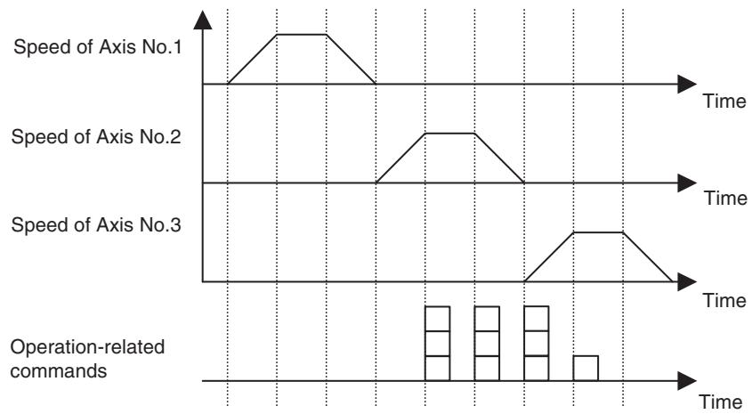
Stepping in Pass Mode
When a movement command is being executed in Pass Mode, execution of the next block starts when deceleration starts for the current block. Even with single execution commands, two blocks will be executed simultaneously in one cycle. Other single or multiple execution commands (besides the movement commands) operate just as they do in the Stop Mode
In the 'Single Block Operation Mode', regardless of SINGLE/MULTI, one block is executed at a time, so executions do not overlap even in a movement command.
Operation image:
It takes three cycles to execute one single execution command and the maximum number of simultaneous executions is set to four. No Parallel Branching.
| No. | Command | Cycle | Comments | |||||||||||
| 1 | 2 | 3 | 4 | 5 | 6 | 7 | 8 | 9 | 10 | 11 | 12 | |||
| 1 | SINGLE (Not axis movement) | ■ | ■ | ■ | It does not overlap with No.2. | |||||||||
| 2 | SINGLE (Axis movement) | ■ | ■ | ■ | Execution starts after com-mand No.1 is completed. | |||||||||
| 3 | SINGLE (Axis movement) | ■ | ■ | ■ | Execution starts when com-mand No.2 starts deceleration. | |||||||||
| 4 | MULTI | ■ | Executed during execution of command No.3. | |||||||||||
| 5 | MULTI | ■ | Executed during execution of command No.3. | |||||||||||
| 6 | SINGLE (Axis movement) | ■ | ■ | ■ | Execution starts when com-mand No.3 starts deceleration. | |||||||||
| 7 | MULTI | ■ | Executed during execution of command No.6. | |||||||||||
| 8 | MULTI | ■ | Executed during execution of command No.6. | |||||||||||
| 9 | SINGLE (Axis movement) | ■ | ■ | ■ | Execution starts when com-mand No.6 starts deceleration. | |||||||||
The diagram below is the operation image of the above table if 4 single execution commands (No.2, 3, 6, and 9) are axis movement commands for Axis 1, 2, 3, and 4 and all the multiple execution commands are operation-related (arithmetic, logic, etc.) commands.
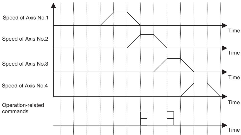
Stepping When Parallel Branch is executed
When parallel branch is executed, the branched program steps per sequence.
The execution of commands within the same scan is restricted by system parameters just as it is in the Stop Mode. When the number of parallel branches written in the motion program is smaller than the maximum number of simultaneous executions, the number of commands that can be executed simultaneously in a sequence can be obtained by dividing the maximum number of simultaneous executions by the number of parallel branches (the remainder to be omitted).
In the 'Single Block Operation Mode', regardless of SINGLE/MULTI, one block is executed at a time.
Operation image 1:
It takes three cycles to execute one single execution command and the maximum number of simultaneous executions is set to two. The number of parallel Branches is set to two. (In this case, the number of simultaneous executions per branch is one.)
| No. | Command | Com-mand | Cycle | Cycle | ||||||||||||||||
| 1 | 2 | 3 | 4 | 5 | 6 | 7 | 8 | 9 | 1 | 2 | 3 | 4 | 5 | 6 | 7 | 8 | 9 | |||
| 1 | PARALLEL | ■ | ■ | |||||||||||||||||
| 2 | SINGLE | MULTI | ■ | ■ | ■ | ■ | ||||||||||||||
| 3 | MULTI | MULTI | ■ | ■ | ||||||||||||||||
| 4 | MULTI | MULTI | ■ | ■ | ||||||||||||||||
| 5 | MULTI | SINGLE | ■ | ■ | ■ | |||||||||||||||
| 6 | JOINT | JOINT | ■ | ■ | ||||||||||||||||
| 7 | JWAIT | ■ | ■ | |||||||||||||||||
The following diagram can be applicable as for an operation image if the single execution commands moving axes 1 and 2 while the multiple execution commands perform calculations.
The diagram below is the operation image of the above table if 2 single execution commands are axis movement commands for Axis 1 and 2 and all the multiple execution commands are operation-related (arithmetic, logic, etc.) commands.
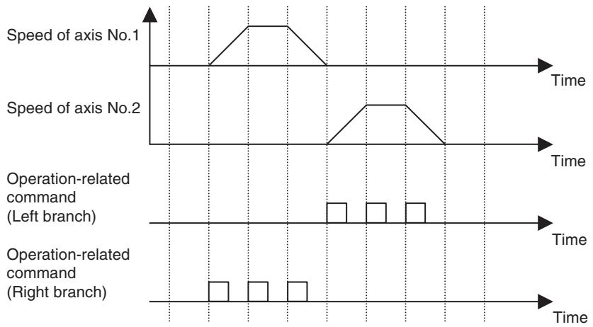
Operation Image (2):
It takes three cycles to execute one single execution command and the maximum number of simultaneous executions is set to four. The number of parallel branches is set to two. (In this case, the number of simultaneous executions per branch is two.)
| No. | Command | Command | Cycle | Cycle | ||||||||||||||||
| 1 | 2 | 3 | 4 | 5 | 6 | 7 | 8 | 9 | 1 | 2 | 3 | 4 | 5 | 6 | 7 | 8 | 9 | |||
| 1 | PARALLEL | ■ | ■ | |||||||||||||||||
| 2 | SINGLE | MULTI | ■ | ■ | ■ | ■ | ||||||||||||||
| 3 | MULTI | MULTI | ■ | ■ | ||||||||||||||||
| 4 | MULTI | MULTI | ■ | ■ | ||||||||||||||||
| 5 | MULTI | SINGLE | ■ | ■ | ■ | ■ | ||||||||||||||
| 6 | JOINT | JOINT | ■ | ■ | ||||||||||||||||
| 7 | JWAIT | ■ | ■ | |||||||||||||||||
The diagram below is the operation image of the above table if 2 single execution commands are axis movement commands for Axis 1 and 2 and all the multiple execution commands are operation-related (arithmetic, logic, etc.) commands.
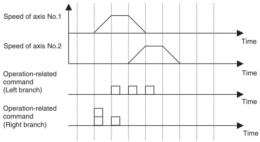
Note
(1) JOINT command is treated as a single execution command because it always waits for completion of the previous block execution.
(2) JWAIT command is treated as a single execution command because it always waits for completion of JOINT command's execution in each sequence.
6-1-4 Program System
This section explains the program of the MC Unit.
- Programs are composed of the motion task main programs and motion task sub-programs.
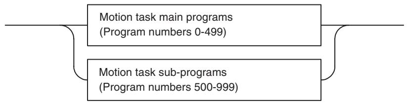
- A program can contain up to 800 blocks.
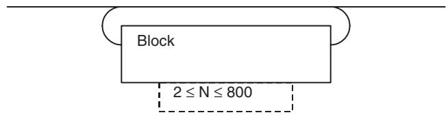
- A block contains a command, a semi-colon, and a comment (this may be omitted).

- An NSTOP command, and an ABL/INC command, can be added at the beginning of a block.
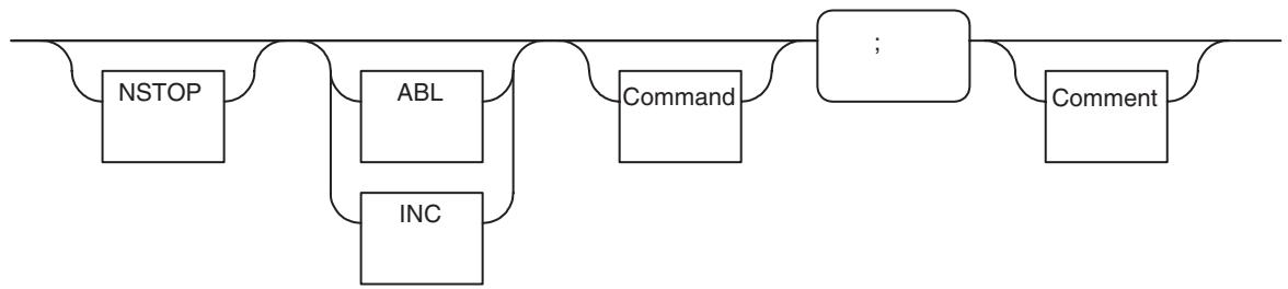
6-1-5 Axis Movement Operation
Acceleration/Deceleration Pattern
- Setting acceleration/deceleration patterns with the following system parameters makes it possible to select symmetrical/asymmetrical acceleration/deceleration patterns.
- Acceleration/deceleration time cannot be changed during axis movement.
| No. | Name | Usage |
| P00M02 | Interpolation feed acceleration time | Motion commands: MOVEL/MOVEC/MOVETRAV (Operand F sets the speed.) |
| P00M03 | Interpolation feed deceleration time | |
| P2AA05 | Rapid feed acceleration time | Motion commands: MOVE/MOVEI/DATUM/MOVET (Factors other than Operand F (parameters, etc.) set the speed) |
| P2AA06 | Rapid feed deceleration time | |
| P2AA07 | Manual feed acceleration time | Axis control bits: JOG/STEP/Machine origin return/Origin search |
| P2AA08 | Manual feed deceleration time |
- S-curve acceleration/deceleration can be realized by multiplying movement averaging filter and trapezoidal acceleration/deceleration.
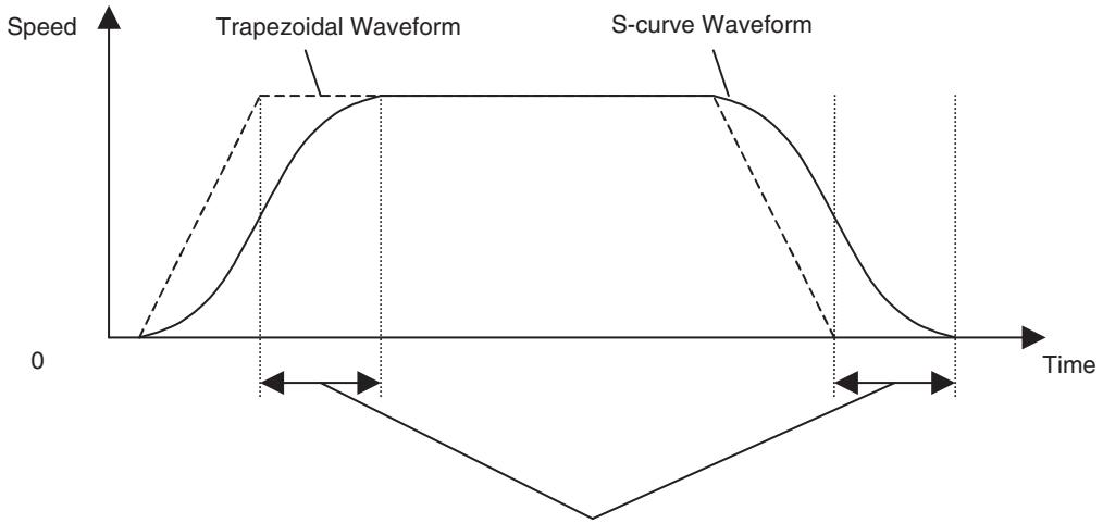
S-curve time constant = Delay until operation reaches the intended speed
- Enable/disable or S-curve time constant for S-shape acceleration/deceleration can be set using the following system parameters:
| No. | Name | Usage |
| P00M04 | Interpolation feed S-curve filter enable | Motion commands: MOVEL/MOVEC (Operand F sets the speed.) |
| P00M05 | Interpolation S-curve time constant | |
| P2AA09 | Rapid feed S-curve filter enable | Motion commands: MOVE/MOVEI/MOVET (Factors other than Operand F (parameters, etc.) set the speed) |
| P2AA11 | Rapid feed time constant | |
| P2AA10 | Rapid feed S-curve filter enable | Axis control bits: JOG/STEP |
| P2AA12 | Manual feed time constant |
- If the travel time is less than the acceleration time plus the deceleration time, a triangular curve will be created, as shown below.
Case 1:
PTP Operation Commands (MOVE, MOVEI, DATUM, and MOVET)
The rates of acceleration and deceleration will be maintained while moving in a triangular curve.
P2AA01: Maximum rapid feed rate
P2AA05: Rapid feed acceleration time
P2AA06: Rapid feed deceleration time
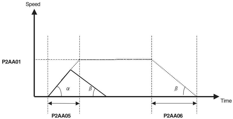
Case 2: Interpolation Commands (MOVEL, MOVEC, and MOVETRAV)
1) P00M06 (pass mode) = 0 or 1
The rates of acceleration and deceleration will be maintained while moving in a triangular curve.
F speed: Speed specified in the interpolation command
P00M02: Interpolation feed acceleration time
P00M03: Interpolation feed deceleration time
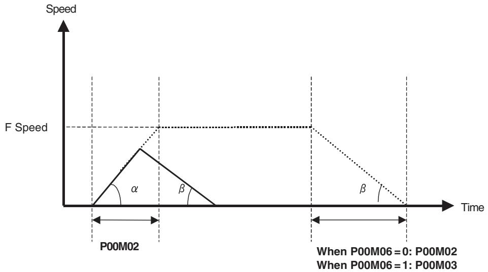
2) P00M06 (pass mode) = 2 or 3
The rates of acceleration and deceleration will be maintained while moving in a triangular curve.
This setting differs from P00M06 (pass mode) = 0 or 1 in that the maximum interpolation feed rate is used when calculating the acceleration and deceleration times.
P00M01: Maximum interpolation feed rate
P00M02: Interpolation feed acceleration time
P00M03: Interpolation feed deceleration time
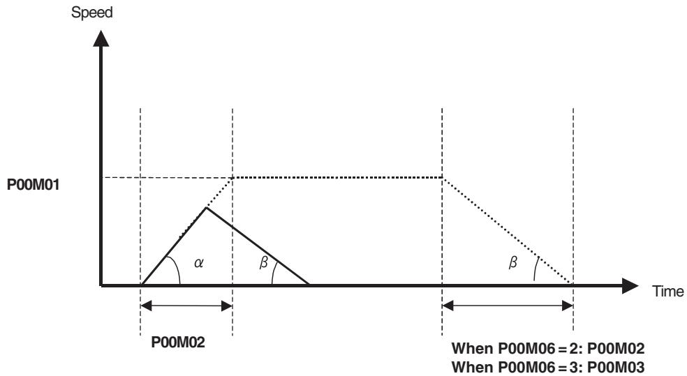
- Relations between Axis Operation Function and Acceleration/Deceleration
| Classifica- tion | Function | Acceleration time | Deceleration time | Time or Acceleration / Deceleration | S-curve filter select S-curve filter time constant |
| Axis move-ment | MOVE | P2AA05: Rapid feed acceleration time | P2AA06: Rapid feed deceleration time | Acceleration/deceler-ation | P2AA09: Rapid feed S-curve filter enable P2AA11: Rapid feed S-curve filter time constant |
| MOVEL | P00M02: Interpola- tion feed acceleration time Refer to Acceleration/ Deceleration Times and Pass Mode (page 254) for details. | P00M03: Interpola- tion feed deceleration time Refer to Acceleration/ Deceleration Times and Pass Mode (page 254) for details. | Normally: time Pass Mode with fixed acceleration: Acceler-ation/deceleration | P00M04: Interpola- tion feed S-curve filter enable P00M05: Interpola- tion feed S-curve time constant | |
| MOVEC | P00M02: Interpola- tion feed acceleration time Refer to Acceleration/ Deceleration Times and Pass Mode (page 254) for details. | P00M03: Interpola- tion feed deceleration time Refer to Acceleration/ Deceleration Times and Pass Mode (page 254) for details. | Time | P00M04: Interpola- tion feed S-curve filter enable P00M05: Interpola- tion feed S-curve time constant | |
| DATUM | P2AA05: Rapid feed acceleration time | ← | Acceleration/deceler-ation | --- | |
| MOVEI | P2AA05: Rapid feed acceleration time | ← | Acceleration/deceler-ation | P2AA09: Rapid feed S-curve filter enable P2AA11: Rapid feed S-curve time constant | |
| MOVET | P2AA05: Rapid feed acceleration time | ← | Acceleration/deceler-ation | P2AA09: Rapid feed S-curve filter enable P2AA11: Rapid feed S-curve time constant | |
| MOVETRAV | P00M02: Interpola- tion feed acceleration time Refer to Acceleration/ Deceleration Times and Pass Mode (page 254) for details. | P00M03: Interpola- tion feed deceleration time Refer to Acceleration/ Deceleration Times and Pass Mode (page 254) for details. | Time | --- | |
| CAM | Depending on the CAM table | Depending on the CAM table | Depending on the CAM table | --- | |
| Axis opera- tion start | MOVELINK | Calculated with oper- and A and other travel distances | Calculated with oper- and D and other travel distances | Depending on the travel distance. (Time image) | --- |
| CAMBOX | Depending on the CAM table | Depending on the CAM table | Depending on the CAM table | --- | |
| CONNECT | --- | --- | --- | --- | |
| SYNC | P2AA05: Rapid feed acceleration time Note When trailing | ← | Acceleration/deceler- ation Note When trailing | --- | |
| ADDAX | --- | --- | --- | --- | |
| SPEED | Specified by operand T | Specified by operand T | Time | --- | |
| TORQUE | Specified by operand T | Specified by operand T | Time | --- | |
| Axis opera- tion end | SYNCR | P2AA05: Rapid feed acceleration time | P2AA06: Rapid feed deceleration time | Acceleration/deceler- ation | --- |
| ADDAXR | --- | --- | --- | --- | |
| SPEEDR | --- | Specified by operand T | Acceleration/deceler- ation | --- | |
| TORQUER | --- | Specified by operand T | Acceleration/deceler- ation | --- | |
| Axis con- trol bits | JOG | P2AA07: Manual feed acceleration time | P2AA08: Manual feed deceleration time | Acceleration/deceler- ation | P2AA10: Manual feed S-curve filter enable P2AA12: Manual feed S-curve time constant |
| STEP | P2AA07: Manual feed acceleration time | P2AA08: Manual feed deceleration time | Acceleration/deceler- ation | P2AA10: Manual feed S-curve filter enable P2AA12: Manual feed S-curve time constant | |
| Origin search | P2AA07: Manual feed acceleration time | ← | Acceleration/deceler- ation | --- | |
| Machine ori- gin return | P2AA07: Manual feed acceleration time | P2AA08: Manual feed deceleration time | Acceleration/deceler- ation | --- |
Operating Mode
Axis movement commands can be executed in either of two operating modes; one is Pass Mode and the other is Stop Mode. They can be changed using PASSMODE or STOPMODE command in a program.
Pass Mode:
In Pass Mode, when a consecutive operation has been specified, the program proceeds smoothly to the next operation without confirming completion of positioning.
Note that there are some commands that are always executed in Stop Mode.
Stop Mode:
In Stop Mode, when a consecutive operation has been specified, the program always confirms completion of positioning (in-position). Once positioning has been completed, the next operation is started.
For confirming positioning completion, either in-position range (set in the servo parameter) or No. 2 in-position range (set in system parameter) is used.
Which range is to be used depends on each command.
The following table shows the relations between each command and operating modes.
| Command | Function | Stop Mode | Pass Mode | Remark |
| MOVE | POSITIONING | ○ | × | |
| MOVEL | LINEAR INTERPOLATION | □ | ○ | |
| MOVEC | CIRCULAR INTERPOLATION | □ | ○ | |
| DATUM | ORIGIN SEARCH | ○ | × | |
| MOVEI | INTERRUPT FEEDING | ○ | × | |
| MOVET | TIME-SPECIFIED POSITIONING | ○ | × | |
| MOVETRAV | TRAVERSE | □ | ○ or □ | Stop Mode for linked traverse |
| CAM | ELECTRONIC CAM, SINGLE AXIS | ○ | × | Acceleration/deceleration time is not known, so this command cannot be executed in Pass Mode. |
Executed according to the selected mode.
× Always executed in Stop Mode.
□: The No. 2 in-position range is used.
Explanation of Pass Mode with fixed acceleration:
- The Pass Mode operation is usually performed based on acceleration or deceleration time, however, the Pass Mode with fixed acceleration can be used when the parameter [P00M06: Pass Mode select] is set to 2 or 3, and the MOVEL command is executed with only one axis specified.
| Parameter No. | Name | Value |
| P00M06 | Pass Mode Select | 0: Based on interpolation acceleration time + Pass Mode with fixed acceleration disabled1: Based on interpolation deceleration time + Pass Mode with fixed acceleration disabled2: Based on interpolation acceleration time + Pass Mode with fixed acceleration enabled3: Based on interpolation deceleration time + Pass Mode with fixed acceleration enabled |
- Interpolation override in Pass Mode with fixed acceleration will be disabled during deceleration due to shortage of remaining travel distance. (The very last value will be held.)
- Under the following conditions in Pass Mode with fixed acceleration, the passing operation cannot be performed. The operation is stopped with deceleration once (does not wait for No.2 in-position, so it is not a Stop Mode operation), and proceeds to the next operation.
Distance required for deceleration stop from current speed > Travel distance of the next block
Restrictions and Conditions for Pass Mode
The following setting and programming conditions must be met to enable continuous axis operation without stopping in pass mode.
1,2,3...
- The number of parallel branches (P00002) divided by the number of parallel branches in the program must be 2 or higher.
Ex) If P00002 is set to 4 and there are no parallel branches used in the program (i.e., if the number of branches in the program is 1), 4 divided by 1 equal 4, so this condition would be met.
- Interpolation commands (MOVE, MOVEC, and MOVETRAV) must be used continuously.
| Ex) Correct Notation MOVEL [J01] 100 [J02] 200; MOVEL [J01] 200 [J02] 300; | Incorrect Notation MOVEL [J01] 100 [J02] 200; #IWOA00 = 1; Not an interpolation command, so op- eration will not be continuous. |
| MOVEL [J01] 300 [J02] 400; | MOVEL [J01] 100 [J02] 200; |
| : | : |
| If the following conditions are met, multiple execution commands can be used between interpolation commands. • The pass mode (P00M06) is set to 0 or 1. • The operation time of one of the interpolation commands is longer than the processing time for the multiple execution command. Ex) PASSMODE; WHILE #MW0000 == 0; INC MOVEL [J02] 100 F1000; WEND; | |
| Acceleration/Deceleration Times and Pass Mode | The acceleration/deceleration times can be changed as required during pass operation. Specifically, the numbers of the parameters where the acceleration/deceleration times are set are substituted for input variables to specify acceleration/deceleration times. This called bank selection. Bank selection is possible not only in pass mode, but also in stop mode. PRGRAM P000 Q00000003; PARAM P00111 = 100; Interpolation feed acceleration time bank 1 for task 1 PARAM P00112 = 200; Interpolation feed acceleration time bank 2 for task 1 : PARAM P00120 = 1000; Interpolation feed acceleration time bank 10 for task 1 : PASSMODE; #IW0A00 = 1; Selects task 1 bank 1 acceleration/deceleration time MOVE [J01] 1000 F100000; Accelerates using the selected acceleration/deceleration time #IW0A00 = 2; Selects task 1 bank 2 acceleration/deceleration time MOVE [J01] 20000 F200000; Passes using the selected acceleration/deceleration time : END; |
| Note | P00111 to P00120 are task parameters. They can be set in advance from the Support Tool running on a computer. |
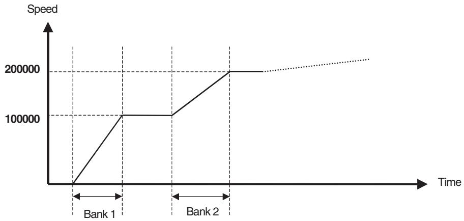
Parameters and Variables Used for Bank Selection
The following system parameters and input variables are used for bank selections.
System Parameters
The following ten parameters are provided for each task.
| No. | Name | Setting range | Initial value | Unit |
| P00M11 | Interpolation feed acceleration/deceleration time bank 1 | 0-60000 | 100 | ms |
| P00M12 | Interpolation feed acceleration/deceleration time bank 2 | 0-60000 | 100 | ms |
| P00M13 | Interpolation feed acceleration/deceleration time bank 3 | 0-60000 | 100 | ms |
| P00M14 | Interpolation feed acceleration/deceleration time bank 4 | 0-60000 | 100 | ms |
| P00M15 | Interpolation feed acceleration/deceleration time bank 5 | 0-60000 | 100 | ms |
| P00M16 | Interpolation feed acceleration/deceleration time bank 6 | 0-60000 | 100 | ms |
| P00M17 | Interpolation feed acceleration/deceleration time bank 7 | 0-60000 | 100 | ms |
| P00M18 | Interpolation feed acceleration/deceleration time bank 8 | 0-60000 | 100 | ms |
| P00M19 | Interpolation feed acceleration/deceleration time bank 9 | 0-60000 | 100 | ms |
| P00M20 | Interpolation feed acceleration/deceleration time bank 10 | 0-60000 | 100 | ms |
Input Variables
The following variables are used to specify banks for each task. If a value not between 0 and 10 is specified, the acceleration and deceleration times in P00M02 and P00M03 will be used.
| No. | Bits | Name | Setting range | Initial value |
| IW0A00 | 00-15 | Acceleration/deceleration bank selection for motion task 1 | 0-10 | 0 |
| IW0A01 | 00-15 | Acceleration/deceleration bank selection for motion task 2 | 0-10 | 0 |
| IW0A02 | 00-15 | Acceleration/deceleration bank selection for motion task 3 | 0-10 | 0 |
| IW0A03 | 00-15 | Acceleration/deceleration bank selection for motion task 4 | 0-10 | 0 |
| IW0A04 | 00-15 | Acceleration/deceleration bank selection for motion task 5 | 0-10 | 0 |
| IW0A05 | 00-15 | Acceleration/deceleration bank selection for motion task 6 | 0-10 | 0 |
| IW0A06 | 00-15 | Acceleration/deceleration bank selection for motion task 7 | 0-10 | 0 |
| IW0A07 | 00-15 | Acceleration/deceleration bank selection for motion task 8 | 0-10 | 0 |
Acceleration/Deceleration Times and Bank Selections
The acceleration/deceleration times used in pass mode are described below.
Programming Example
PASSMODE;
IW0A00 = X; Selects task 1 bank X acceleration/deceleration time
MOVE [J01] 10000 F100000;
IW0A00 = Y; Selects task 1 bank Y acceleration/deceleration time
MOVE [J01] 20000 F200000;
END;
Speed
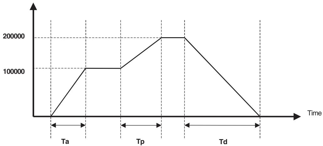
| P00M06 | Acceleration time (Ta) | Passing time (Tp) | Deceleration time (Td) | |
| Value | Meaning | |||
| 0 | Interpolation acceleration time + Pass mode with fixed acceleration disabled | Previously selected bank | Previously selected bank | Previously selected bank |
| 1 | Interpolation deceleration time + Pass mode with fixed acceleration disabled | P00M02 | Previously selected bank | Previously selected bank |
| 2 | Interpolation acceleration time + Pass mode with fixed acceleration enabled | Previously selected bank | Acceleration: Previously selected bankDeceleration: P00M03 | P00M03 |
| 3 | Interpolation deceleration time + Pass mode with fixed acceleration enabled | P00M02 | Acceleration: P00M02Deceleration: Previously selected bank | Previously selected bank |
Note Acceleration: When the current speed command is faster than the previous speed command
Deceleration: When the current speed command is slower than the previous speed command
Setting the Acceleration and Deceleration Times for Interpolation Separately (Unit Ver. 3.1 or Later)
Acceleration and deceleration times can be set separately for linear interpolation, circular interpolation, and traverse using the bank function.
Setting Procedure
1,2,3...
- Set P00004 (unit function selection) bit 13 (interpolation acceleration/deceleration bank switching option) to 1.
Data of banks 1 to 10 will be allocated for acceleration and deceleration times.
| Parameter No. | IORD/ IOWR Address | Name | Bits | Value | Initial value |
| P00004 | 5003h | Unit func-tion select | 13 | Interpolation acceleration/ deceleration bank switching option. Selects the bank switching method for acceleration and deceleration times used during interpolation accelera-tion/deceleration. 0: Selects the same banks for acceleration and deceleration times. 1: Selects different banks for acceleration and deceleration times. | 0 |
For example, the acceleration time can be set to bank 1 during acceleration, and the deceleration time can be set to bank 5 during deceleration.
| Task No. | Number | P00004.13 = 0 | P00004.13 = 1 | ||
| Name | Name | ||||
| M Task | P00M11 | Interpola- tion feed accelera- tion time | Bank 1 | Interpola- tion feed accelera- tion time | Bank 1 |
| P00M12 | Bank 2 | Bank 2 | |||
| P00M13 | Bank 3 | Bank 3 | |||
| P00M14 | Bank 4 | Bank 4 | |||
| P00M15 | Bank 5 | Bank 5 | |||
| P00M16 | Bank 6 | Interpola- tion feed decelera- tion time | Bank 1 | ||
| P00M17 | Bank 7 | Bank 2 | |||
| P00M18 | Bank 8 | Bank 3 | |||
| P00M19 | Bank 9 | Bank 4 | |||
| P00M20 | Bank 10 | Bank 5 | |||
- The following variables are used to specify the bank number during acceleration and deceleration.
| Variable address | P00004.13 = 0 | P00004.13 = 1 | ||
| Name | Specification | Name | Specification | |
| IW0A00 | Acceleration/ deceleration bank selection for motion task 1 | Selects sys- tem parame- ters to use as interpolation feed accelera- tion/decelera- tion times. 1 to 10: Uses P00M11 to P00M20 as interpolation feed accelera- ation/deceler- ation times. | Motion task 1 acceleration time bank selection | Selects sys- tem parame- ters to use as interpolation feed accelera- tion/decelera- tion times. 1 to 5: Uses P00M11 to P00M15 as interpolation feed accelera- ation time. Other: P00M02: Uses interpo- lation feed acceleration time |
| IW0A01 | Acceleration/ deceleration bank selection for motion task 2 | Motion task 2 acceleration time bank selection | ||
| IW0A02 | Acceleration/ deceleration bank selection for motion task 3 | Motion task 3 acceleration time bank selection | ||
| IW0A03 | Acceleration/ deceleration bank selection for motion task 4 | Other: P00M02: Uses interpo- lation feed acceleration time | Motion task 4 acceleration time bank selection | |
| IW0A04 | Acceleration/ deceleration bank selection for motion task 5 | P00M03: Uses interpo- lation feed deceleration time. | Motion task 5 acceleration time bank selection | |
| IW0A05 | Acceleration/ deceleration bank selection for motion task 6 | Motion task 6 acceleration time bank selection | ||
| IW0A06 | Acceleration/ deceleration bank selection for motion task 7 | Motion task 7 acceleration time bank selection | ||
| IW0A07 | Acceleration/ deceleration bank selection for motion task 8 | Motion task 8 acceleration time bank selection | ||
| IW0A08 | Reserved | --- | Motion Task 1 deceleration time bank selection | Selects system parameters to use as interpolation feed deceleration time.1 to 5: P00M16 to P00M20 are used as interpolation feed deceleration time. Other: P00M03: Uses interpolation feed deceleration time |
| IW0A09 | Reserved | --- | Motion Task 2 deceleration time bank selection | |
| IW0A0A | Reserved | --- | Motion Task 3 deceleration time bank selection | |
| IW0A0B | Reserved | --- | Motion Task 4 deceleration time bank selection | |
| IW0A0C | Reserved | --- | Motion Task 5 deceleration time bank selection | |
| IW0A0D | Reserved | --- | Motion Task 6 deceleration time bank selection | |
| IW0A0E | Reserved | --- | Motion Task 7 deceleration time bank selection | |
| IW0A0F | Reserved | --- | Motion Task 8 deceleration time bank selection | |
Acceleration/Deceleration Times and Pass Mode
By setting P0004 bit 13 to 1, the acceleration and deceleration times for pass mode operation take on the values as shown in the following table.
Banks can be selected for values fixed by system parameters P00M02 (interp-. polation feed acceleration time) or P00M03 (interpolation feed deceleration time).
| Value of P00M06 | Operating mode | P00004.13 = 0 | P00004.13 = 1 | ||
| Acceleration time | Deceleration time | Acceleration time | Deceleration time | ||
| 0 Interpolation acceleration time + Pass mode with fixed acceleration disabled | Pass Mode | Bank selection | Bank selection | Acceleration time bank selection | Deceleration time bank selection |
| Stop Mode | Bank selection | Value set for P00M03 | Acceleration time bank selection | Deceleration time bank selection | |
| 1 Interpolation deceleration time + Pass mode with fixed acceleration disabled | Pass Mode | Value set for P00M02 | Bank selection | Acceleration time bank selection | Deceleration time bank selection |
| Stop Mode | Value set for P00M02 | Bank selection | Acceleration time bank selection | Deceleration time bank selection | |
| 2 Interpolation acceleration time + Pass mode with fixed acceleration enabled | Pass Mode | Bank selection | Value set for P00M03 | Acceleration time bank selection | Deceleration time bank selection |
| Stop Mode | Bank selection | Value set for P00M03 | Acceleration time bank selection | Deceleration time bank selection | |
| 3 Interpolation deceleration time + Pass mode with fixed acceleration enabled | Pass Mode | Value set for P00M02 | Bank selection | Acceleration time bank selection | Deceleration time bank selection |
| Stop Mode | Value set for P00M02 | Bank selection | Acceleration time bank selection | Deceleration time bank selection | |
Timing of Bank Switching
In principle, bank switching is enabled when the block after bank switching is executed.
| Operating mode | Valid timing |
| Not in pass operation during pass mode or stop mode | Enabled when the block after switching is executed. |
| Acceleration and deceleration time is specified in pass operation | Enabled when the block executed after switching begins to decelerate. |
| Fixed acceleration in pass operation | Enabled when the block after switching is executed. |
Overview of Bank Switching
Acceleration/deceleration time bank switching is specified in the motion program and not the ladder program.
When system parameter P00004 bit 13 is set to 1 (selects banks for acceleration/deceleration times separately), four patterns of operation images (one for each setting of P00M06) are possible.
Stop Mode (P00106 = 0: Acceleration Time Specification)
Enabled when the block after parameter change is executed.
Program Example:
Set P00M11 to P00M15 and P00M16 to P00M20 beforehand.
Execution with PROG P0001 Q0001; motion task 1 (P00106 = 0: acceleration time specification)
STOPMODE;
IW0A00=0; Acceleration bank 0 specification
IW0A08=0; Deceleration bank 0 specification
DATUM [J01]0 [J02]0;
ABL MOVEL [J01]100000 F1000000;
WAIT #SL0204 > 20000; Command position exceeds 20000
IW0A00=1; Acceleration bank 1 specification
IW0A08=1; Deceleration bank 1 specification
ABL MOVEL [J01]0 F1000000;
WAIT #SL0204 < 80000; Command position exceeds 80000
IW0A00=2; Acceleration bank 2 specification
IW0A08=2; Deceleration bank 2 specification
ABL MOVEL [J01]100000 F1000000;
END;
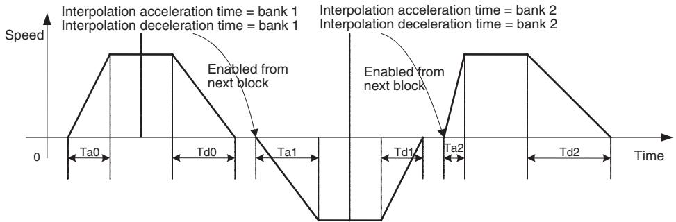
Interpolation acceleration time + Fixed acceleration pass mode disabled (P00106 = 0)
Enabled when the block executed after parameter change begins to decelerate.
Program Example:
Set P00M11 to P00M15/P00M16 to P00M20 beforehand.
Execution with PROG P0002 Q0001; motion task 1.
PASSMODE;
IW0A00=1; Acceleration bank 1 specification
DATUM [J01]0;
ABL MOVEL [J01]100000 F600000;
WAIT #SL0204 > 20000; Command position exceeds 20000
IW0A00=2; Acceleration bank 2 specification
ABL MOVEL [J01]200000 F1000000;
WAIT #SL0204 > 170000; Command position exceeds 170000
IW0A00=3; Acceleration bank 3 specification
ABL MOVEL [J01]300000 F600000;
ABL MOVEL [J01]400000 F1000000;
END;
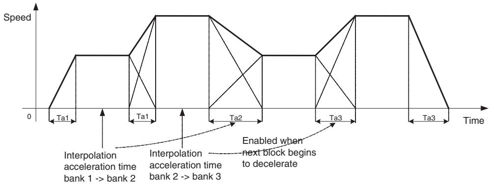
Interpolation deceleration time + Fixed acceleration pass mode disabled (P00106 = 1)
Enabled when the block executed after parameter change begins to decelerate.
Program Example:
Set P00M11 to P00M15/P00M16 to P00M20 beforehand.
Execution with PROG P0002 Q0001; motion task 1.
PASSMODE;
IW0A00=1; Acceleration bank 1 specification
IW0A08=1; Deceleration bank 1 specification
DATUM [J01]0;
ABL MOVEL [J01]100000 F600000;
WAIT #SL0204 > 20000; Command position exceeds 20000
IW0A08=2; Deceleration bank 2 specification
ABL MOVEL [J01]200000 F1000000;
WAIT #SL0204 > 170000; Command position exceeds 170000
IW0A08=3; Deceleration bank 3 specification
ABL MOVEL [J01]300000 F600000;
ABL MOVEL [J01]400000 F1000000;
END;
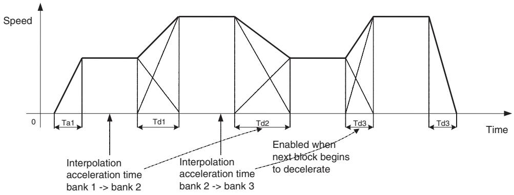
Interpolation acceleration time + Fixed acceleration pass mode enabled (P00106 = 2)
Interpolation deceleration time + Fixed acceleration pass mode enabled (P00106 = 3)
Enabled when block after parameter change is executed.
Program Example:
Set P00M11 to P00M15/P00M16 to P00M20 beforehand.
Execution with PROG P0002, Q0001; motion task 1
PMD;
IW0A00=1; Acceleration bank 1 specification
IW0A08=1; Deceleration bank 1 specification
ZRN [JO1]0;
ABS MVS [J01]100000 F600000;
LOW #SL0204 > 20000; Command position exceeds 20000
IW0A00=2; Acceleration bank 2 specification
ABS MVS [J01]200000 F1000000;
LOW #SL0204 > 17000; Command position exceeds 170000
IW0A00=3; Acceleration bank 3 specification
ABS MVS [J01]300000 F1500000;
ABS MVS [J01]400000 F1000000;
LOW #SL0204 > 350000; Command position exceeds 350000
IW0A08=2; Deceleration bank 2 specification
ABS MVS [J01]500000 F600000;
LOW #SL0204 > 450000; Command position exceeds 450000
IW0A08=3; Deceleration bank 3 specification
END;
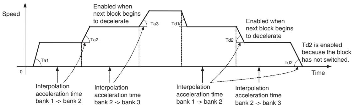
Rapid Feed Rate
Rapid Feed Rate
The feed rate for the axis movement command MOVE and MOVEI can be set in the parameter [P2AA03: Rapid feed rate].
The speed can be changed using the same parameter [P2AA03: Rapid feed rate] before executing positioning.
Upper Limit of Command Value
The value set in the parameter [P2AA01: Maximum rapid feed rate] limits the speed after override, the speed specified in the operand V of MOVET command, or the speed after override for MOVET command.
Override
Changing Speed with the PLC
The speed can be changed during operations by multiplying override to the rapid feed rate.
The axis override is used for rapid feed rate.
Range of the axis override is between 0 and 327.67% . When a value outside of the range is set, the override 0% is used.
For details of the axis override, see 7-4-4 Axis Control Bits, Axis Status Bits (page 472).
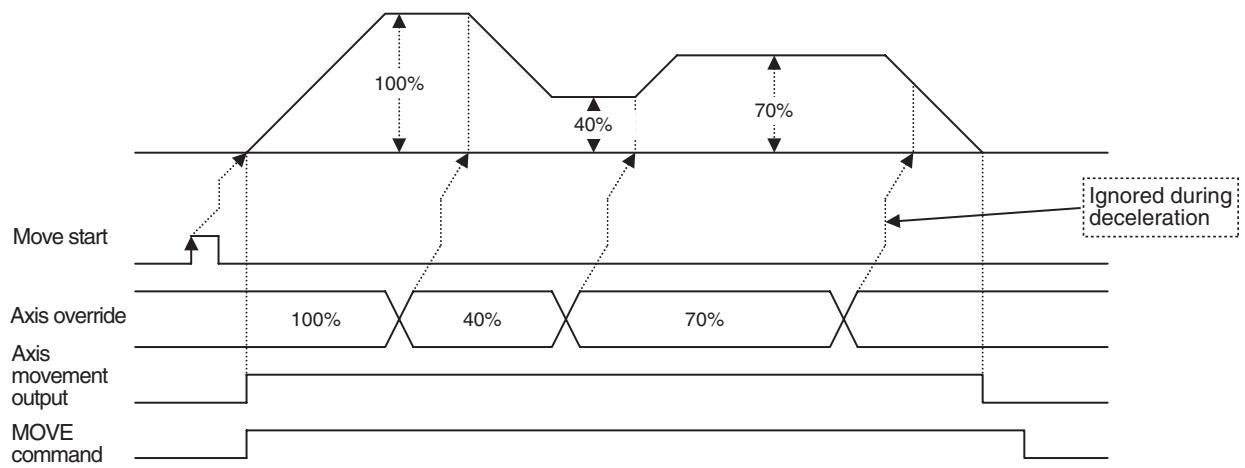
Changing Speed with the Program
The feed rate from the motion program can be added to the override that changes the axes feed rate from the ladder program in order to conduct high speed positioning.
The actual speed is calculated as follows:
Actual speed = Axes feed rate × (Axes override + Internal override)
Commands that can be specified by adding override from the motion program are listed in the following table.
| Classifica- tion | Instruction | Rate to which override is applied | Remarks |
| Axes move-ment | MOVE | Rapid feed rate | --- |
| DATUM | Origin return feed rate | --- | |
| MOVEI | Rapid feed rate, external positioning rate | --- | |
| MOVET | Rapid feed rate | --- | |
| CAM | --- | Override from ladder pro- gram is disabled. |
-
The range of numerical values for axes override will not change even if the internal override is added.
-
The range of numerical values is 0.00% to 327.67% .
- The axes override value is valid only when the axes override enable relay is ON. When it is OFF, the value is 100% .
- If the entered value is not within the stated range, the following values will be assigned.
Negative values: 0%
Values exceeding 327.67%: 327.67%
- Examples of Actual Calculated Speed Are Shown in the Following Table.
| Axes override | Internal override | Actual override |
| 100.00% | 100.00% | 200.00% |
| 100.00% | -100.00% | 0.00% |
| -100.00% | 100.00% | 0.00% |
| -100.00% | -100.00% | 0.00% |
| 200.00% | 200.00% | 327.67% |
Interpolation Feed Rate
Interpolation Feed Rate
The feed rate for the axis movement commands MOVEL, MOVEC, and MOVETRAV can be set in the Operand F in motion programs. Overwriting the value in F can change the feed rate though it is not valid during operations. During motion program execution, the previously specified interpolation speed will be held until the newly set speed is enabled. (Modal data.)
Upper Limit of Command Value
The value set in the parameter [P00M01: Maximum interpolation feed rate] limits the speed after override, the speed specified in the operand F.
If the speed of axes exceeds the speed specified in the parameter [P2AA01: Maximum rapid feed rate], the speed will be limited as shown in the table below:
| Command | Speed limit operation |
| MOVEL | Interpolation feed rate is limited in order to prevent the speed of the axis that has the longest travel distance from exceeding the speed specified in the parameter [P2AA01: Maximum rapid feed rate]. |
| MOVEC | Speed of axes is not checked. |
| MOVETRAV | Interpolation feed rate is limited in order to prevent the speed of rotation axis from exceeding the speed specified in the parameter [P2AA01: Maximum rapid feed rate]. |
Override
Multiplying the override and the interpolation feed rate can change speed of the operation in progress. The task override is used for the interpolation feed rate. Range of the task override is between 0 and 327.67% . When a value outside of the range is set, the override 0% is used. If the distributed interpolation feed rates on the axes exceed the speeds specified in the parameter [P2AA01: Maximum rapid feed rate] for the axes, the maximum speed of the axis that has the longest travel distance (the fastest axis) will be used as the upper limit.
For details on the task override, see 7-4-3 Motion Task Control Bits (page 443).
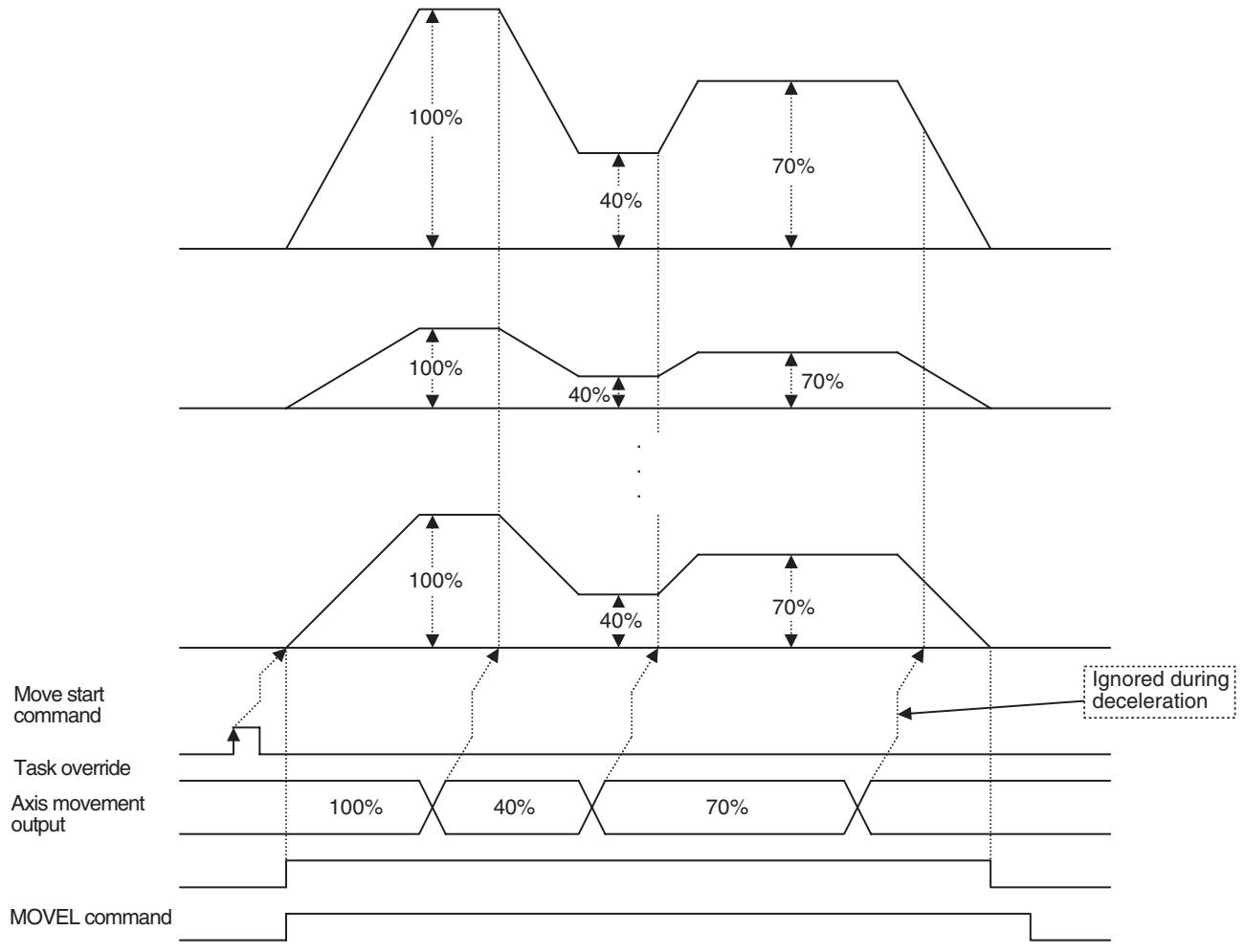
Commands using the Counter Latch Function
The following six commands use the counter latch function:
| Command | Purpose for using counter latch function | Role of latch signal |
| DATUM: Origin search | Detects origin | The trigger to decide the final stop position |
| MOVEI: Interrupt feeding | Detects external signal input position | The trigger to decide the final stop position |
| MOVELINK: Link operation | Detects link start position | The trigger to start synchronization |
| CAMBOX: Electronic Cam, Synchronous | Detects link start position | The trigger to start synchronization |
| SYNC: Trailing Synchroniz- nization | Detects position of marker sensor ON. | The trigger to start synchroni- zation |
| LATCH: Present position latch | Detects latch position | The trigger to store the latch position |
With variables in the following table, whether or not the counter latch has been completed can be confirmed:
| Variable | Specifications | Remark |
| Output variables: Axis status bits: bit 10 [Counter latch completed] | 0: Started to execute function that requires counter latch 1: Completed counter latch | Relation to SW022A 0: SW022A = 0, 1, 2 1: SW022A = 3, 4 |
| System variables: SW022A + 30 × (Axis No. - 1) | 0: No latch request 1: Parameter being overwritten 2: Latch being requested 3: Latch completed (next request: disabled) 4: Latch completed (next request: enabled) | Only the latch signal input during "latch being requested" can be accepted. |
Counter latch positions are stored in each variable shown in the following table:
| Command: Function | Storage | Content |
| DATUM: Origin search | System variablesSW0208 + 30 × (Axis No. – 1) | Counter latch position on machine coordinate system |
| MOVEI: Interrupt feeding | ||
| MOVELINK: Link operation | ||
| CAMBOX: Electronic Cam, Synchronous | ||
| SYNC: Trailing Synchronizatio | ||
| LATCH: Present position latch | "Latch position storage address" in the operand of a command | Counter latch position on the currently selected coordinate system |
Latch signals used for counter latch can be set in the following parameters:
| Commands | Parameters | Value: Latch signals | |
| DATUM: Origin search | P4AA06: Origin deter-mine signal | 0: Phase-C (Z) 1: External input signal 1 2: External input signal 2 3: External input signal 3 | |
| Commands | Parameters | Value: Latch signals | |
| MOVEI: Interrupt feeding | P5AA08: External input signal select 1 | @ @%%$$##h | 0: Phase-C (Z) |
| MOVELINK: Link operation | ## (MOVEI: Interrupt feeding) | 1: External input signal 1 | |
| CAMBOX: Electronic Cam, Synchronous | $$ (MOVELINK: Link operation) | 2: External input signal 2 | |
| %% (CAMBOX: Electronic cam, Synchronous) | 3: External input signal 3 | ||
| SYNC: Trailing Synchroniza- tion | @@ (SYNC: Trailing Synchroniza- tion) | ||
| LATCH: Present position latch | P5AA09: External input signal select 2 | 000000##h | 0: Phase Z(C) |
| ## (LATCH: Present position latch) | 1: External input signal 1 | ||
| 2: External input signal 2 | |||
| 3: External input signal 3 | |||
Simultaneous Commands (Overlap) to the Same One Axis
The operations when several commands are executed simultaneously on the same one axis are as follows:
| Command executed simultaneously | Classification | Axis movement | Axis operation | Axis operation cancel | Setting | ||||||||||||||||||||||||||||
| Function/Name | Positioning | Linear interpolation | Circular interpolation | Origin search | Interrupt feeding | Time-specified positioning | Electrical CAM, Single axis | Link operation | Electronic CAM, Synchronous | Electronic shat | Trailing synchronization | Travel distance super impose | Speed control | Torque control | Trailing synchronization cancel | Travel distance super impose cancel | Speed control cancel | Torque control cancel | Target position change | Parameter value change | Workpiece coordinate system OFFSET change | Present value latch | |||||||||||
| Classification | Function/Name | Command | Stepping | MOVE | MOVEL | MOVEC | DATUM | MOVEI | MOVET | MOVERAV | CAM | MOVELINK (M) | MOVELINK (S) | CAMEBOX (M) | CAMEBOX (S) | CONNECT (M) | CONNECT (S) | SYNC (M) | SYNC (S) | ADDAX (M) | ADDAX (S) | SPEED | TORQUE | SYNC | ADXAIR | SPEED | TORQUER | TORQUE | MVOEMODI | PARAM | OFFPOS | LATCH | |
| Axis movement | Positioning | MOVE | E | E | E | E | E | E | E | A | E | A | E | A | E | A | E | A | A | D | D | B | B | B | B | A | A | A | A | ||||
| Linear interpolation | MOVEL | E | E | E | E | E | E | E | A | E | A | E | A | E | A | E | A | A | D | D | B | B | B | B | G | A | A | A | |||||
| Circular interpolation | MOVEC | E | E | E | E | E | E | E | A | E | A | E | A | E | A | E | A | A | D | D | B | B | B | B | B | A | A | A | |||||
| Origin search | DATUM | E | E | E | E | E | E | E | C | E | C | E | A | E | C | E | A | A | D | D | B | B | B | B | B | A | A | C | |||||
| Interrupt feeding | MOVEI | E | E | E | E | E | E | E | C | E | C | E | A | E | C | E | A | A | D | D | B | B | B | B | B | A | A | C | |||||
| Time-specified positioning | MOVET | E | E | E | E | E | E | E | A | E | A | E | A | E | A | E | A | A | D | D | B | B | B | B | B | A | A | A | |||||
| Traverse | MOVETRAV | E | E | E | E | E | E | E | A | E | A | E | A | E | A | E | A | A | D | D | B | B | B | B | B | A | A | A | |||||
| Electronic CAM, Single axis | CAM | E | E | E | E | E | E | E | A | E | A | E | A | E | A | E | A | A | D | D | B | B | B | B | B | A | A | A | |||||
| Axis operation cancel | Axis operation | Axis operation | ||||||||||||||||||||||||||||||||||||||||||||||||||||||||||||||||||||||||||||||||||||||||||||||||||||||||||||||||||||||||||||||||||||||||||||||||||||||||||||||||||||||||||||||||||||||||||||||||||||||||||||||||||||||||||||||||||||||||||||||||||||||||||||||||||||||||||||||||||||||||||||||||||||||||||||||||||||||||||||||||||||||||||||||||||||||||||||||||||
| Function Name | Axis operation | Axis operation | Axis operation | Axis operation | Axis operation | Axis operation | Axis operation | Axis operation | Axis operation | Axis operation | Axis operation | Axis operation | Axis operation | Axis operation | Axis operation | Axis operation | Axis operation | Axis operation | Axis operation | Axis operation | Axis position | Axis operation | Axis operation | Axis operation | Axis operation | Axis operation | Axis operation | Axis operation | Axis operation | Axis operation | Axis operation | Axis operation | Axis operation | Axis operation | Axis operation | Axis operation | Axis operation | Axis operation | Axis operation | Axis operation | Axis位置 | Command | Function Name | Command | Function Name | Command | Stepping | Command | Stepping | Command | Command | Stepping | Command | Command | Stepping | Command | Command | Stepping | Command | Command | Stepping | Command | Command | Stepping | Command | Command | Stepping | Command | Command | Stepping | Command | Command | Stepping | Command | Command | Stepping | Command | Command | Stepping | Command | Command | Stepping | Command | Command | Stepping | Command | Command | Stepping | Command | Command | Stepping | Command | Control | Command | Command | Stepping | Command | Command | Stepping | Command | Command | Stepping | Command | Command | Stepping | Command | Command | Stepping | Command | Command | Stepping | Command | Command | Stepping | Command | Command | Stepping | Command | Command | Stepping | Command | Command | Stepping | Command | Command | Stepping | Command | Command | Stepping | Command | Command | Stepping | Command | Command | Stepping | Control | Command | Command | Command | Stepping | Command | Command | Stepping | Command | Command | Stepping | Command | Command | Stepping | Command | Command | Stepping | Command | Command | Stepping | Command | Command | Stepping | Command | Command | Stepping | Command | Command | Stepping | Command | Command | Stepping | Command | Command | Stepping | Command | Command | Stepping | Command | Command | Stepping | Command | Command | Stepping | Command | Command | Stepping | Command | Command | Stepping | Command | Command | Stepping | Command | Command | Stepping | Command | Command | Stepping | Command | Command | Stepping | Command | Command | Stepping | Command | Command | Stepping | Command | Command | Stepping | Command | Command | Stepping | Command | Command | Stepping | Command | Command | Stepping | Command | Command | Stepping | Command | Command | Stepping | Command | Command | Stepping | Command | Command | Stepping | Command | Command | Stepping | Command | Command | Stepping | Command | Command | Stepping | Command | Command | Stepping | Command | Command | Stepping | Command | Command | Stepping | Command | Command | Stepping | Command | Command | Stepping | Command | Command | Stepping | Command | Command | Stepping | Command | Command | Stepping | Command | Command | Stepping | Command | Command | Starexcap | Time-specified positioning | |||||||||||||||||||||||||||||||||||||||||||||||||||||||||||||||||||||||||||||||||||||||||
| Axis operation cancel | TSURFACE control | TSURFACE control | TSURFACE control | TSURFACE control | TSURFACE control | TSURFACE control | TSURFACE control | TSURFACE control | TSURFACE control | TSURFACE control | TSURFACE control | TSURFACE control | TSURFACE control | TSURFACE control | TSURFACE control | TSURFACE control | TSURFACE control | TSURFACE control | TSURFACE control | TSURFACE control | TSURFACEcontrol | TSURFACE control | TSURFACE control | TSURFACE control | TSURFACE control | TSURFACE control | TSURFACE control | TSURFACE control | TSURFACE control | TSURFACE control | TSURFACE control | TSURFACE control | TSURFACE control | TSURFACE control | TSURFACE control | TSURFACE control | TSURFACE control | TSURFACE control | TSURFACE control | TSURFACE control | TSURFACE控制 | TSURFACE control | TSURFACE control | TSURFACE control | TSURFACE control | TSURFACE control | TSURFACE control | TSURFACE control | TSURFACE control | TSURFACE control | TSURFACE control | TSURFACE control | TSURFACE control | TSURFACE control | TSURFACE control | TSURFACE control | TSURFACE control | TSURFACE control | TSURFACE control | TSURFACE control | TSURFACE Control | TSURFACE control | TSURFACE control | TSURFACE control | TSURFACE control | TSURFACE control | TSURFACE control | TSURFACE control | TSURFACE control | TSURFACE control | TSURFACE control | TSURFACE control | TSURFACE control | TSURFACE control | TSURFACE control | TSURFACE control | TSURFACE control | TSURFACE control | TSURFACE control | TSURFACE control | TSURFACEControl | TSURFACE control | TSURFACE control | TSURFACE control | TSURFACE control | TSURFACE control | TSURFACE control | TSURFACE control | TSURFACE control | TSURFACE control | TSURFACE control | TSURFACE control | TSURFACE control | TSURFACE control | TSURFACE control | TSURFACE control | TSURFACE control | TSURFACE control | TSURFACE control | TSURFACE control | TSURFACE 控制 | TSURFACE control | TSURFACE control | TSURFACE control | TSURFACE control | TSURFACE control | TSURFACE control | TSURFACE control | TSURFACE control | TSURFACE control | TSURFACE control | TSURFACE control | TSURFACE control | TSURFACE control | TSURFACE control | TSURFACE control | TSURFACE control | TSURFACE control | TSURFACE control | TSURFACE control | TSURFACE | |||||||||||||||||||||||||||||||||||||||||||||||||||||||||||||||||||||||||||||||||||||||||||||||||||||||||||||||||||||||||||||||||||||||||||||||||||||||||||||||||||||||||||||||||||||||||||||||||||||||||||||||||||||||||||||||||||||||||||
| Command executed simultaneously | Classification | Axis movement | Axis operation | Axis operation cancel | Setting | ||||||||||||||||||||||||||||
| Function/Name | Positioning | Linear interpolation | Circular interpolation | Origin search | Interrupt feeding | Time-specified positioning | Traverse | Electronic CAM, Single axis | Link operation | Electronic CAM, Synchronous | Electronic shaft | Trailing synchronization | Travel distance super impose | Speed control | Torque control | Trailing synchronization cancel | Travel distance super impose cancel | Speed control cancel | Torque control cancel | Target position change | Parameter value change | Workpiece coordinate system OFFSET change | Present value latch | ||||||||||
| Classification | Function/Name | Command | Stepping | MOVE | MOVEL | MOVEC | DATUM | MOVEI | MOVET | MOVETRAV | CAM | MOVELINK (M) | MOVELINK (S) | CAMBOX (M) | CAMBOX (S) | CONNECT (M) | CONNECT (S) | SYNC (M) | SYNC (S) | ADDAX (M) | ADDAX (S) | SPEED | TORQUE | SYNC | ADDAXR | SPEED | TORQUER | TORQUER | PARAM | OFFPOS | LATCH | ||
| Setting | Target position change | MOVEMODI | A | A | A | A | A | A | A | A | A | A | A | A | A | A | A | A | A | A | A | A | A | A | A | A | A | A | A | A | |||
| Parameter value change | PARAM | A | A | A | A | A | A | A | A | A | A | A | A | A | A | A | A | A | A | A | A | A | A | A | A | A | A | A | A | ||||
| Workpiece coordinate system OFFSET change | OFFPOS | A | A | A | A | A | A | A | A | A | A | A | A | A | A | A | A | A | A | A | A | A | A | A | A | A | A | A | A | ||||
| Present value Latch | Present value Latch | A | A | A | C | C | A | A | A | C | A | C | A | A | A | C | A | A | A | A | A | A | A | A | A | A | A | A | H | ||||
| Meaning | |
| A | Can be executed. |
| B | The function executed later will be ignored. |
| C | Can be executed when no latch is requested. However, when latch is being requested and the function is executed, the alarm [301Ah:Counter latch resource violation] will occur and the program will be interrupted. Also, if the function is executed when writing the latch range parameters, the alarm [2016h: Same axis specification multiplicity] will occur, and the program will be interrupted. |
| D | Alarm [2014h: Control mode error] will occur, and the program will be interrupted. |
| E | Alarm [2016h: Same axis specification multiplicity] will occur, and the program will be interrupted. |
| F | Alarm [2018h: Synchronous slave axis specification error] will occur, and the program will be interrupted. |
| G | Only MOVEMODI during MOVEL: Can be executed if a single axis is specified for each command. Otherwise, the function executed later will be ignored. |
| H | Only latch cancel can be executed. Other cases will be as follows: When executed in parallel, the alarm [2016: Same axis specification multiplicity] will occur and the program will be interrupted. When executed in series, the alarm [301A: Counter latch resource violation] will occur and the program will be interrupted. When executed continuously, the alarm [2016: Same axis specification multiplicity] will occur and the program will be interrupted. |
| I | Only SPEEDR/TORQUER for the master axis: The function executed later will be ignored. Note that, however, if the master axis is under speed or torque control, SPEEDR/TORQUER will be executed to end the operation. |
Changing Control Mode
There are three different types of control mode for the MC Unit; [Position control mode], [Speed control mode], and [Torque control mode].
Switching method and the behaviors are as shown below:
| Mode before switch | Mode after switch | Switching method | Behavior |
| Position | Speed | • Execute SPEED command when the axis is being stopped. | When executing SPEED command during axis movement, the alarm [2014: Control mode error] will occur. |
| Position | Torque | • Execute TORQUE command when the axis is being stopped. | When executing TORQUE command during axis movement, the alarm [2014: Control mode error] will occur. |
| Speed | Position | • Execute a command for position control mode after SPEED command was executed to switch to the position control mode. | When executing a command for position control mode without executing SPEED command first, the alarm [2014: Control mode error] will occur. |
| •Execute MOVE command. | When executing MOVE command without executing SPEED command, the speed of the operation changes smoothly. | ||
| Speed | Torque | •Execute TORQUE command after SPEED command was executed to switch to position control mode. •Execute TORQUE command. | When executing TORQUE command without executing SPEED command first, the torque command 0 is used after the switch because the torque command value in the speed control mode is unknown. To change torque smoothly, monitor the torque in speed control mode, and execute the block with torque command value that was monitored in TORQUE command of 0 torque change rate. |
| Torque | Position | •Execute TORQUER command | When executing a command (MOVE, etc.) for position control mode in torque control mode, the alarm [2014: Control mode error] will occur. |
| Torque | Speed | •Execute SPEED command after TORQUER command was executed to switch to position control mode. | When executing SPEED command in torque control mode, the alarm [2014: Control mode error] will occur. |
To stop axis (speed = 0) in speed control mode started by SPEED command, execute the SPEEDDR command (speed control cancel).
The waveform at this point (i.e. when stopping) will follow the speed change rate specified in SPEEDCR command.
Similarly, to stop axis (torque = 0) in torque control mode started by TORQUE command, execute the TORQUER command (torque control cancel).
The waveform at this point (i.e. when stopping) will follow the torque change rate specified in TORQUER command.
Note
As in the following cases, however, the operation is stopped (or started) without executing SPEEDR or TORQUER command. Therefore, the speed change rate or torque change rate specified in the previous SPEED or TORQUE command is used.
- When an alarm occurred
- When a program ended
- When a program was interrupted
- When a program was restarted after interruption.
S-curve Filter & Stop Mode/Pass Mode
Movement averaging filter is used for the S-curve acceleration/deceleration of the MC Unit.
A command of the next block can be executed during S-curve deceleration. However, if the command is to be executed after completion of the previous command's output (as it should be for CAM, etc.), STOPMODE or PASS-MODE command can be used to control the execution.
When MOVEL MOVE command was executed in Pass Mode:
Program example:
PROG P0001 Q00000001;
PASSMODE;
INC MOVEL [J01] 10000 F100000; Interpolation feed S-curve filter enable
INC MOVE [J01] 10000; Rapid feed S-curve filter disable END;

When MOVEL MOVE command was executed in Stop Mode:
Program example:
PROG P0001 Q00000001;
STOPMODE;
INC MOVEL [J01] 10000 F100000;
INC MOVE [J01] 10000;
END;
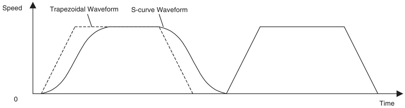
6-1-6 Synchronous Command
There are five different types of synchronous commands.
- MOVELINK: Link operation start
- CAMBOX: Electronic cam, synchronous
- CONNECT: Electronic shaft
SYNC: Trailing synchronization - ADDAX: Travel distance superimpose
Master Axis
- Any MC Unit axis can be used as a master axis. Axis declaration by PROG command (program start) is not required for the axes to be used only as master axes.
Slave Axis
- Whether to use the specified speed of the master axis or the feedback speed can be selected using the operand of each synchronous command.
- If a master axis is the virtual axis, feedback speed = specified speed.
- For the counter axis, specified speed = feedback speed.
- There is no limit on the number of slave axes per one master axis.
-
The axis that is already operating as a slave axis can be specified as a master axis for another synchronous command.
-
Only the axes that are declared by PROG command (program start) can be used as slave axes.
- A master axis that is already operating cannot be specified as a slave axis for another synchronous command, except for that the master axis of ADDAX (Travel distance superimpose) command can be specified as a slave axis of another synchronous command.
- When a slave axis already in synchronization is specified as a slave axis for another master axis, the alarm [2016h: Same axis specification multiplicity] will occur. In the cases below, however, the alarm will not occur and a new synchronous operation will be established.
| Operating axis | Overlapping command | Operation |
| MOVELINK slave axis | MOVELINK slave axis | Interrupts the current synchronization and establish a new synchronization. |
| CAMBOX slave axis | ||
| CAMBOX slave axis | MOVELINK slave axis | |
| CAMBOX slave axis | ||
| CONNECT slave axis | CONNECT slave axis |
Program Restart
When a program is stopped after establishing synchronization and resumed, the following operations will be as described below depending on the command.
MOVELINK, CAMBOX:
The latest interrupted synchronization is re-executed. Whether the condition for starting the synchronization is met or not met will be reflected when it is restarted.
CONNECT:
The latest interrupted synchronization is re-executed.
SYNC:
There is no re-execution after interruption.
ADDAX:
The latest interrupted synchronization is re-executed.
Note
While a program is being stopped, synchronization is also being stopped. Therefore, there will be some position deviation between axes if the axis is moved.
Precautions in Using Synchronous Commands
The precautions are as follows:
1,2,3...
- Start the master axis of a synchronous command only after all the slave axes have recognized and processed the command.
Especially when the master and slave axes are in different tasks, or in different blocks of parallel branching, provide interlocking, etc. so that the master axis starts operating only after all the slave axes have recognized and processed the command.
Program example
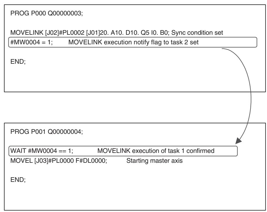
- Set the resolution for the master axis of the synchronous command higher than the one of slave axes.
Since slave axes cannot operate with the unit system smaller than the one of the master axis, setting a larger travel distance for slave axes than the travel distance 1 of the master axis causes off-and-on operations. Make sure to set parameters so that "Master axis travel distance > Slave axes travel distance" is true.
In this case, the problem lies not in the resolution for 1 motor rotation on each motor, but in the relations on travel distances between the master and slave axes in synchronization.
An example is shown using the following parameters.
| Parameter setting value | [J01] | [J02] | ||
| Axis parameter | P5AA02 | Position command decimal point position | 2 | 4 |
| P5AA04 | Command unit/1 machine rotation | 36000 | 100000 | |
| P5AA05 | Gear ratio 1 (motor rotation speed) | 5 | 1 | |
| P5AA06 | Gear ratio 2 (machine rotation speed) | 1 | 1 | |
| Motor parameter | 9001h | No. of encoder pulses (×4) | 65536 | 65536 |
Program
MOVELINK [J02]6000 [J01]100. A50. D50. Q5 I0. B0;
According to the conditions mentioned above, the travel distance (pulse) of each axis for linking distance will be as follows:
9001h [No. of encoder pulses/1 motor rotation] × P5AA05 [on motor]
Pulse [on motor] = Command unit [on machine] × P5AA04 [command unit/1 machine rotation] × P5AA06 [on machine]
- No. of pulses for the linking distance of the master axis [J01]:
When 100. of [J01] is converted from the immediate value to the command unit,
Command unit = 100 /0.01(unit of P5AA02) = 10000 [on machine]
Put the result in the formula (1):
Pulse [on motor] = 10000 [on machine] × (65536 × 5) / (36000 × 1)
= 91022.22 = 91022 [pulse]---(2)
- No. of pulses for the linking distance of the slave axis [J02]:
Pulse [on motor] = 6000 [on machine] × (65536 × 1) / (36000 × 1)
= 10922.6 = 10922 [pulse]---(3)
According to the results (2) and (3), the relations between the master axis [J01] and the slave axis [J02] on the travel distance (pulse) within the linking distance is:
Master axis [J01] Slave axis [J02]
91022 [pulse] > 10922 [pulse]
In this case, the travel distance of the master axis is larger than the one of the slave axis. Thus, the condition "Master axis travel distance > Slave axis travel distance" is satisfied.
Processing Required When the Command Execution Completion for MOVELINK, CAMBOX Is Set to "At the Same Time with the Command Start"
By setting the link option of the synchronous commands MOVELINK and CAMBOX to "At the same time with the command start" for the command execution completion, the program can execute a single execution command (axis movement, etc.) on a slave axis different from the one previously used.
However, when a new single execution command such as axis movement, etc. is to be executed after completion of the previous synchronous operation, the operation of the new command is started (specifying the same slave axis as the one previously, or currently being used causes an alarm.) before the synchronous operation is completed unless a program that monitors completion of the synchronous operation is arranged. The following is the program example.
Program
Task 1
PROG P0001 Q0000005; Declaration of the program
(1)MOVELINK [J01]2000 [J02]1000 A200 D200 Q1; Synchronizes J01 with J02
(2)#MW0000 = 0055; Writes "55" to global variable 0000
(3)MOVE [J03]1500; Moves J03 to the position 1500
(4)WAIT #SW0228 = = 0000; Stops stepping till J01 not being executed
(5)MOVE [J01]3000; Moves J01 to the position 3000
END;
Task 2
PROG P0001 Q0000002; Declaration of the program
(2)WAIT #MW0000 = = 0055; Stops stepping till global variable 0000 becomes "55"
MW0000 = 0; Writes "0" to global variable 0000
(6)MOVE [J02]2000; Moves J02 to the position 2000
END;
Timing chart
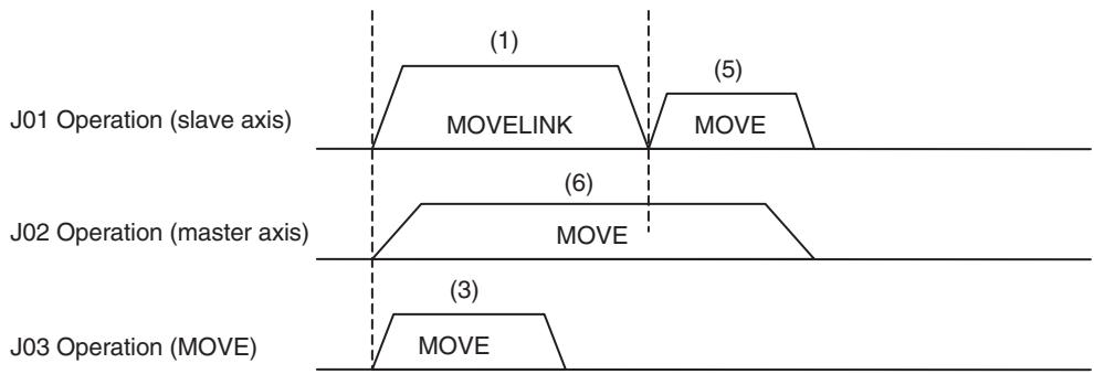
Explanation
1,2,3...
- Having J02 as a master axis with the travel distance of 1000, J01 is moved to the position of 2000 through synchronization. In this operation, the acceleration interval of the slave axis is specified between the synchronization start position and 200 of the master axis travel distance while the deceleration interval is specified between the synchronization end position and 200 of the master axis travel distance. The program advances with the link option set to "1" (link operation is started at the same time as the command execution start, the command execution is completed at the same time as the command execution start).
- Using the global variable #MW0000, the program notifies task 2 that MOVELINK block has been executed. (It is used as interlocking for the master axis.) As the response, task 2 resets the content of the global variable (#MW0000 = 0); and then executes the command for (6).
- J03 is executed simultaneously during the operation of J01.
- Monitoring the command execution status of the system variable #SW0228 (for Axis 1), the advancement of task 1 is held until the command code becomes "0000" (no axis movement).
- J01 is finished with the MOVELINK command of (1) after (4), another single execution command can be executed.
6-1-7 Modal Data
Data that is selected by the following commands, and that can be omitted later in the program, is called modal data.
| Group | Command | Description |
| 1 | ABL/INC | Interprets the specified position either as an absolute value specification or as an incremental value specification. |
| 2 | PASSMODE/ STOPMODE | Sets the axis movement command operating mode to either Pass Mode or Stop Mode |
| 3 | Operand F | Sets the speed command value of the interpolation command inOperand F |
Initializing
When power is turned ON or when program execution is started in Start Mode 0 without executing END command, initialization is executed according to the default settings of the parameters. Default setting parameter is maintained for each task.
| Group | Command | Default value | Parameter No. |
| 1 | ABL/INC | ABL | P00M07 (M = 1-8) |
| 2 | PASSMODE/ STOPMODE | PASSMODE | P00M08 (M = 1-8) |
| 3 | Operand F | F = 0 | P00M09 (M = 1-8) |
Calling Sub-program
If a sub-program has been called using the GOSUB command, all modal data is inherited. Also, when the operation returns to the main program from sub-program, all modal data is inherited.
Parallel Branching
If parallel branching has been executed using the PARALLEL command, modal data for all the branches is inherited.
Modal data that has been changed during each branch will not affect other branches.
When branches join together again, the modal data of the leftmost branch is inherited to subsequent blocks.
END Command Execution
The execution of END command does not initialize modal data.
6-1-8 Nesting
Nesting levels for nest-able commands are as follows:
| Command | Motion task |
| GOSUB | 5 layers |
| WHILE-WEND | 10 layers |
| FOR-NEXT | 10 layers |
| IF-ELSE-ENDIF | 10 layers |
6-1-9 Unit for Time
The unit for time used for the following commands is [ms].
The minimum command unit is 1msec, however, the actual resolution is determined based on the system scan cycle (remainder to be omitted).
| Command | Time |
| MOVET | Positioning time |
| CAM | Cam execution time |
| Dwell | Dwell time |
6-1-10 Conditional Expression
Conditional expressions can be used for the following commands.
| Command | Function |
| WAIT | Wait for Condition to be Met |
| STOPOP | Optional End |
| IF | Conditional Branching |
| WHILE | Repeat While |
Conditional expressions are shown in the following table. Immediate values or variables are the only the objects of comparison. If other data types are used, the program cannot be downloaded.
| Conditional Expression | Format |
| Equal to | (Immediate value or Variable) == (Immediate value or Variable) |
| Not equal to | (Immediate value or Variable)<> (Immediate value or Variable) |
| Greater than | (Immediate value or Variable)>(Immediate value or Variable) |
| Less than | (Immediate value or Variable)<(Immediate value or Variable) |
| Equal to or greater than | (Immediate value or Variable)> = (Immediate value or Variable |
| Equal to or less than | (Immediate value or Variable)< = (Immediate value or Variable) |
6-1-11 Arithmetic Command
Data type
Bit Type:
- For the operation using data of bit type, every operand in the operation must be bit type.
- Integer immediate value [0] and [1] are treated as the bit type.
Other Types:
- Besides bit type, all other types observe the priority sequence described below. Real-number type > Long type > Word type
- Operation is performed with the type of the highest priority, and the operation result is converted to the type on the left and stored.
- Integer immediate value is treated as long type, and decimal immediate value is treated as real-number type.
B: Bit type, W: Word type, L: Long type, F: Real-number type, @: Indirect specification
| Classifi-cation | Function | Command | Notation example | Operand | Range | Immediate value | Variable | ||||||
| Inte-ger | Deci-mal point | R/W | B | W | L | F | @ | ||||||
| Simple Arithmetic | Assign | = | #MW- = #MW-; | 1st Term | --- | No | No | Write | Yes | Yes | Yes | Yes | No |
| 2nd Term | Within the operation numerical value range | Yes | Yes | Read | Yes | Yes | Yes | Yes | Yes | ||||
| Add | + | #MW- = #MW- + #MW-; | 1st Term | --- | No | No | Write | No | Yes | Yes | Yes | No | |
| 2nd Term | Within the operation numerical value range | Yes | Yes | Read | No | Yes | Yes | Yes | Yes | ||||
| 3rd Term | Within the operation numerical value range | Yes | Yes | Read | No | Yes | Yes | Yes | Yes | ||||
| Subtract | - | #MW- = #MW- - #MW-; | 1st Term | --- | No | No | Write | No | Yes | Yes | Yes | No | |
| 2nd Term | Within the operation numerical value range | Yes | Yes | Read | No | Yes | Yes | Yes | Yes | ||||
| 3rd Term | Within the operation numerical value range | Yes | Yes | Read | No | Yes | Yes | Yes | Yes | ||||
| Multiply | × | #MW- = #MW-* #MW-; | 1st Term | --- | No | No | Write | No | Yes | Yes | Yes | No | |
| 2nd Term | Within the operation numerical value range | Yes | Yes | Read | No | Yes | Yes | Yes | Yes | ||||
| 3rd Term | Within the operation numerical value range | Yes | Yes | Read | No | Yes | Yes | Yes | Yes | ||||
| Divide | / | #MW- = #MW- / #MW-; | 1st Term | --- | No | No | Write | No | Yes | Yes | Yes | No | |
| 2nd Term | Within the operation numerical value range | Yes | Yes | Read | No | Yes | Yes | Yes | Yes | ||||
| 3rd Term | Within the operation numerical value range | Yes | Yes | Read | No | Yes | Yes | Yes | Yes | ||||
| Quotient | % | #MW- = #MW-% #MW-; | 1st Term | --- | No | No | Write | No | Yes | Yes | Yes | No | |
| 2nd Term | Within the operation numerical value range | Yes | Yes | Read | No | Yes | Yes | Yes | Yes | ||||
| 3rd Term | Within the operation numerical value range | Yes | Yes | Read | No | Yes | Yes | Yes | Yes | ||||
| Exponent | ^ | #MW- = #MW- ^ #MW-; | 1st Term | --- | No | No | Write | No | Yes | Yes | Yes | No | |
| 2nd Term | Within the operation numerical value range | Yes | Yes | Read | No | Yes | Yes | Yes | Yes | ||||
| 3rd Term | Within the operation numerical value range | Yes | Yes | Read | No | Yes | Yes | Yes | Yes | ||||
| Logic oper-ations | OR (Logical OR) | | | #MW- = #MW- | #MW;- | 1st Term | --- | No | No | Write | Yes | Yes | Yes | No | No |
| 2nd Term | LONGMIN- LONGMAX | Yes | Inte-ger | Read | Yes | Yes | Yes | No | Yes | ||||
| 3rd Term | LONGMIN- LONGMAX | Yes | Inte-ger | Read | Yes | Yes | Yes | No | Yes | ||||
| XOR (Logical exclusive OR) | ~ | #MW- = #MW- ~ #MW;- | 1st Term | --- | No | No | Write | No | Yes | Yes | No | No | |
| 2nd Term | LONGMIN- LONGMAX | Yes | Inte-ger | Read | No | Yes | Yes | No | Yes | ||||
| 3rd Term | LONGMIN- LONGMAX | Yes | Inte-ger | Read | No | Yes | Yes | No | Yes | ||||
| AND (Logical AND) | & | #MW- = #MW- & #MW;- | 1st Term | --- | No | No | Write | Yes | Yes | Yes | No | No | |
| 2nd Term | LONGMIN- LONGMAX | Yes | Inte-ger | Read | Yes | Yes | Yes | No | Yes | ||||
| 3rd Term | LONGMIN- LONGMAX | Yes | Inte-ger | Read | Yes | Yes | Yes | No | Yes | ||||
| NOT (Reverse) | ! | #MW- = !#MW;- | 1st Term | --- | No | No | Write | Yes | Yes | Yes | No | No | |
| 2nd Term | LONGMIN- LONGMAX | Yes | Inte-ger | Read | Yes | Yes | Yes | No | Yes | ||||
| Functions | Absolute value | ABS | #MF- = ABS#MF;-; | 1st Term | --- | No | No | Write | No | Yes | Yes | Yes | No |
| 2nd Term | Within the operation numerical value range | Yes | Yes | Read | No | Yes | Yes | Yes | Yes | ||||
| Sine | SIN | #MF- = SIN#MF;-; | 1st Term | --- | No | No | Write | No | Yes | No | Yes | No | |
| 2nd Term | Within the operation numerical value range | Yes | Yes | Read | No | Yes | No | Yes | No | ||||
| Cosine | COS | #MF- = COS#MF;-; | 1st Term | --- | No | No | Write | No | Yes | No | Yes | No | |
| 2nd Term | Within the operation numerical value range | Yes | Yes | Read | No | Yes | No | Yes | No | ||||
| Tangent | TAN | #MF- = TAN#MF;-; | 1st Term | --- | No | No | Write | No | No | No | Yes | No | |
| 2nd Term | Within the operation numerical value range | Yes | Yes | Read | No | No | No | Yes | No | ||||
| ARC Sine | ASIN | #MF- = ASIN#MF;-; | 1st Term | --- | No | No | Write | No | No | No | Yes | No | |
| 2nd Term | Within the operation numerical value range | Yes | Yes | Read | No | No | No | Yes | No | ||||
| ARC Cosine | ACOS | #MF- = ACOS#MF;-; | 1st Term | --- | No | No | Write | No | No | No | Yes | No | |
| 2nd Term | Within the operation numerical value range | Yes | Yes | Read | No | No | No | Yes | No | ||||
| ARC Tan- gent | ATAN | #MF- = ATAN#MF;-; | 1st Term | --- | No | No | Write | No | Yes | No | Yes | No | |
| 2nd Term | Within the operation numerical value range | Yes | Yes | Read | No | Yes | No | Yes | No | ||||
| Square root | SQR | #MF- = SQR#MF;-; | 1st Term | --- | No | No | Write | No | Yes | No | Yes | No | |
| 2nd Term | Within the operation numerical value range | Yes | Yes | Read | No | Yes | No | Yes | No | ||||
| Normal logarithm | EXP | #MF- = EXP#MF;-; | 1st Term | --- | No | No | Write | No | Yes | No | Yes | No | |
| 2nd Term | Within the operation numerical value range | Yes | Yes | Read | No | Yes | No | Yes | No | ||||
| Natural logarithm | LOG | #MF- = LOG#MF;-; | 1st Term | --- | No | No | Write | No | Yes | No | Yes | No | |
| 2nd Term | Within the operation numerical value range | Yes | Yes | Read | No | Yes | No | Yes | No | ||||
| Functions | Decimal | FRAC | #MF- = FRAC#MF-; | 1st Term | --- | No | No | Write | No | No | No | Yes | No |
| 2nd Term | Within the opera- tion numerical value range | Yes | Yes | Read | No | No | No | Yes | No | ||||
| Sign | SGN | #MF- = SGN#MF-; | 1st Term | --- | No | No | Write | No | Yes | Yes | Yes | No | |
| 2nd Term | Within the opera- tion numerical value range | Yes | Yes | Read | No | Yes | Yes | Yes | Yes | ||||
| Bit opera-tions | Specified bit ON | SET | #MB- = SET#MB- & #MB-; | 1st Term | --- | No | No | Write | Yes | No | No | No | No |
| Logic operation expres-sion | --- | --- | --- | --- | --- | --- | --- | --- | --- | ||||
| Specified bit OFF | RESET | #MB- = RESET#MB- & #MB-; | 1st Term | --- | No | No | Write | Yes | No | No | No | No | |
| Logic operation expres-sion | --- | --- | --- | --- | --- | --- | --- | --- | --- | ||||
| Shift right | SFTR | SFTR #MB- N;- | Object to be shifted | --- | No | No | Write | No | Yes | Yes | No | No | |
| Shift amount | Object to be shifted is the word type:1 to 16 Object to be shifted is the long type:1 to 32 | Yes | No | Read | No | Yes | No | No | No | ||||
| Shift left | SFTL | SFTL #MB- N;- | Object to be shifted | --- | No | No | Write | No | Yes | Yes | No | No | |
| Shift amount | Object to be shifted is the word type:1 to 16 Object to be shifted is the long type:1 to 32 | Yes | No | Read | No | Yes | No | No | No | ||||
| Data Operations | BCD→BIN | BIN | #MW- = BIN#MW;-; | 1st Term | --- | No | No | Write | No | Yes | Yes | No | No |
| 2nd Term | In BCD format, Word type: 0 to 9999 Long type: 0 to 99999999 | Yes | Inte-ger | Read | No | Yes | Yes | No | Yes | ||||
| BIN→BCD | BCD | #MW- = BCD#MW;-; | 1st Term | --- | No | No | Write | No | Yes | Yes | No | No | |
| 2nd Term | In BCD format, Word type: 0 to 9999 Long type: 0 to 99999999 | Yes | Inte-ger | Read | No | Yes | Yes | No | Yes | ||||
| Block transfer | XFER | XFER #MW- #MW- N- | Begin-ning of transfer source | --- | No | No | Read | No | Yes | No | No | No | |
| Begin-ning of transfer destina-tion | --- | No | No | Write | No | Yes | No | No | No | ||||
| No. of transfers | Both transfer source and desti-nation are, Sys-tem variable: 1 to (2048 - address) Global general variable: 1 to (8192 - address) Input variable: 1 to (4096 - address) Output variable: 1 to (4096 - address) Task variable: 1 to (128 - address) | Yes | No | Read | No | Yes | No | No | No | ||||
| Clear | CLEAR | CLEAR #MW- N- | Begin-ning of clear | --- | No | No | Write | No | Yes | No | No | No | |
| No. of clears | Global general variable: 1 to (8192 - address) Input variable: 1 to (4096 - address) Output variable: 1 to (4096 - address) Tasks variable: 1 to (128 - address) | Yes | No | Read | No | Yes | No | No | |||||
6-1-12 Data Used for Operand
Immediate Value
There are two kinds of immediate values; integer and decimal number.
The ranges for each immediate value are listed below.
- Integer: Value without decimal point
Minimum value: -2147483648
Maximum value: 2147483647
- Decimal number: Value with decimal point
Minimum value: -2147483648.
Maximum value: 2147483647.
Maximum number of decimals: 30 digits
Maximum number of digits excluding 0: 10 digits
(Negative value: 2147483648, Positive value: 2147483647)
| Number of digits after the decimal point | 1 | 2 | 3 | 4 | 5 | 6 | 7 | 8 | 9 | 10 | 11 | 12 | 13 | 14 | 15 | 16 | 17 | 18 | 19 | 20 | 21 | 22 | 23 | 24 | 25 | 26 | 27 | 28 | 29 | 30 | |||
| Negative value | - | 0 | - | 0 | 0 | 0 | 0 | 0 | 0 | 0 | 0 | 0 | 0 | 0 | 0 | 0 | 0 | 0 | 0 | 0 | 0 | 0 | 0 | 2 | 1 | 4 | 7 | 4 | 8 | 3 | 6 | 4 | 8 |
| Positive value | + | 0 | - | 0 | 0 | 0 | 0 | 0 | 0 | 0 | 0 | 0 | 0 | 0 | 0 | 0 | 0 | 0 | 0 | 0 | 0 | 0 | 2 | 1 | 4 | 7 | 4 | 8 | 3 | 6 | 4 | 7 | |
| Maximum number of digits excluding 0 | ←--------10 digits--------→ | ||||||||||||||||||||||||||||||||
| Maximum number of digits after the decimal point | ←--------30 digits--------→ | ||||||||||||||||||||||||||||||||
Variable
Depending on the operand, variables can be specified instead of immediate values.
Refer to 6-3 Command Details (page 298).
6-1-13 Virtual Axis
The following table describes the differences between virtual axes and real axes.
| Function item | Specifications | |
| Device type | Virtual axis = Virtual Servo axis only. | |
| Servo lock/unlock | Required as well as the real axis. | |
| ABS origin setting | Ignored | |
| Axis machine lock | Ignored | |
| IORD/IOWR of Servo parameters | PARAM command | Alarm [2019h: Parameter setting error] will occur and the program is stopped. |
| IORD/IOWR | Error completion | |
| the Support Tool | Required as well as the real axis, Only writing into MC Unit possible. | |
| Origin search | Same operation as machine origin return. (Positioning to the origin) | |
| Hardware OT | Does not operate because external input cannot be input. | |
| DATUM command | Same operation as execution of the following programs. (Same as when origin search is performed by control bits.)ORIGIN; Machine coordinate system selectABL MOVE [Jxx]0; Positioning to machine coordinate system origin. | |
| MOVEI command | Alarm [3015h: Axis classification error] occurs and the program is stopped. | |
| Master axis of SYNC command | Alarm [3015h: Axis classification error] occurs and the program is stopped. | |
| Link option requiring latch | Alarm [3015h: Axis classification error] occurs and the program is stopped. | |
| SPEED/SPEEDR command (Speed control) | Command is enabled as well as for the real axis. | |
| TORQUE/TORQUER command (Torque control) | Alarm [3015h: Axis classification error] occurs and the program is stopped. | |
| LATCH command | Alarm [3015h: Axis classification error] occurs and the program is stopped. | |
| Other operation commands (e.g., MOVE and MOVEL) | Other operation commands can be specified in the same way as for real axes. | |
| Establishing machine coordinate system origin | The position where power is turned ON is determined as machine coordinate system origin. (Operates in [Origin at power ON] mode.) It is possible to determine a user-specified position as an origin using the axis control bit [Forced origin]. | |
| Present value monitor | Present coordinate system FB position | = Present coordinate system command position |
| Machine coordinate system FB position | = Machine coordinate system command position | |
| Present coordinate system command position | Same as for the real axis | |
| Machine coordinate system command position | Same as for the real axis | |
| Counter latch position | Always 0 | |
| Feedback speed 1 | = Command speed 1 | |
| Feedback speed 2 | Always 0 | |
| Command speed 1 | Same as for the real axis | |
| Command speed 2 | Always 0 | |
| Error | Always 0 | |
| Torque command value | Always 0 | |
| Workpiece origin shift amount | Same as for the real axis | |
| Origin margin | Always 0 | |
| No. of multi-turns | Same as for the real axis | |
| MECHATROLINK servo status | Always 0 | |
| Absolute position setting value | Always 0 | |
| Error on the communication path (Synchronous communication error, etc.) | Does not occur. | |
6-1-14 I/O Axis
The following table describes the differences between axes allocated as I/O and as servo.
| Function item | Specifications | ||
| Axis control bits | All disabled except for "bit 00: Axis alarm reset." | ||
| Axis status bits | bit | Name | ON/OFF status |
| 00 | Axis alarm | As usual, turns ON/OFF. | |
| 01 | Machine origin | Always OFF. | |
| 02 | Busy | Always OFF. | |
| 03 | Servo lock | Always OFF. | |
| 04 | No origin | Always OFF. | |
| 05 | Axis started | Always OFF. | |
| 06 | Positioning completed | Always OFF. | |
| 07 | Positioning completed (No.2) | Always OFF. | |
| 08 | Error counter warning | Always OFF. | |
| 09 | Axis machine lock status | Always OFF. | |
| 10 | Counter latch completed | Always OFF. | |
| 11 | M-10 Warning | Intelligent I/O turns ON/OFF, as usual. | |
| 12 | Reserved | Always OFF. | |
| 13 | Command disabled/enabled | As usual, turns ON/OFF. | |
| 14 | Axis not used/used | Always OFF. | |
| 15 | In manual/automatic mode | Always OFF. | |
| Present value monitor | Always 0 | ||
| Function item | Specifications | ||
| PROG axis declaration | If specified, the alarm [201Ah: Axis declaration error] will occur. | ||
| Usage in each command | If axis No. is specified on axes other than the synchronous master axis, the alarm [2007h: Axis reservation disable] will occur. | ||
| IORD/IOWR of Servo parameters | PARAM command | Alarm [2019h: Parameter setting error] will occur and the program is stopped. | |
| IORD/IOWR command | Error completion | ||
| the Support Tool | Same as for axes without allocation, only reading from the MC Unit can be performed normally. | ||
| Present value preset with IOWR | Error completion | ||
| Error on the communication path | Occurs. | ||
6-1-15 Parameters having Influence on Axis Operation
The list below shows the parameters that affect the axis operation executed by program.
| Section | No. | Name |
| Unit | P00002 | No. of Parallel Branches |
| Unit | P00004 | Unit Function Select |
| M task | P00M01 | Maximum Interpolation Feed rate |
| M task | P00M02 | Interpolation Feed Acceleration Time |
| M task | P00M03 | Interpolation Feed Deceleration Time |
| M task | P00M04 | Interpolation S-curve filter enable |
| M task | P00M05 | Interpolation S-curve Time Constant |
| M task | P00M06 | Pass Mode Select |
| M task | P00M07 | Modal Data Initial Value 1 Move Command Value Select |
| M task | P00M08 | Modal Data Initial Value 2 Operating Mode Select |
| M task | P00M09 | Modal Data Initial Value 3 Interpolation Feed rate |
| M task | P00M10 | Interpolation Speed Multiplier with Decimal Point |
| Axis allocation | P1AA01 | Physical axis setting |
| Axis speed | P2AA01 | Maximum Rapid Feed rate |
| Axis speed | P2AA03 | Rapid Feed rate |
| Axis speed | P2AA05 | Rapid Feed Acceleration Time |
| Axis speed | P2AA06 | Rapid Feed Deceleration Time |
| Axis speed | P2AA09 | Rapid feed S-curve filter enable. |
| Axis speed | P2AA11 | Rapid feed S-curve time constant |
| Axis position | P3AA07 | No.2 In-position Range |
| Axis position | P3AA08 | Feed Forward Gain Enabled/Disabled |
| Axis origin | P4AA01 | Origin Search Method |
| Axis origin | P4AA02 | Origin Search Start Direction |
| Axis origin | P4AA03 | Phase-Z (C) Detection Direction |
| Axis origin | P4AA04 | Origin Deceleration Method |
| Axis origin | P4AA06 | Origin Determine Signal |
| Axis origin | P4AA07 | Origin Search Feed rate |
| Axis origin | P4AA08 | Origin Search Approach Speed |
| Axis origin | P4AA09 | Origin Search Creep Speed |
| Axis origin | P4AA11 | Origin Search Final Travel Distance |
| Axis origin | P5AA01 | Units |
| Axis machine | P5AA02 | Position Command Decimal Point Position |
| Axis machine | P5AA03 | Speed Multiplier with Decimal Point |
| Axis machine | P5AA04 | Command unit/One Machine Rotation |
| Axis machine | P5AA05 | Gear Ratio 1 (Motor Rotation Speed) |
| Axis machine | P5AA06 | Gear Ratio 2 (Machine Rotation Speed) |
| Axis machine | P5AA07 | Axis Feed Mode |
| Axis machine | P5AA08 | External Input Signal Select 1 |
| Axis machine | P5AA09 | External Input Signal Select 2 |
6-1-16 Coordinate System
There are two types of coordinate systems.
Machine coordinate system: Coordinate system determined by the origin search and origin setting. It is fixed for the system.
Workpiece coordinate system: Coordinate system determined by adding the offset to the machine coordinate system. It is unique to the work and there are 3 for each axis
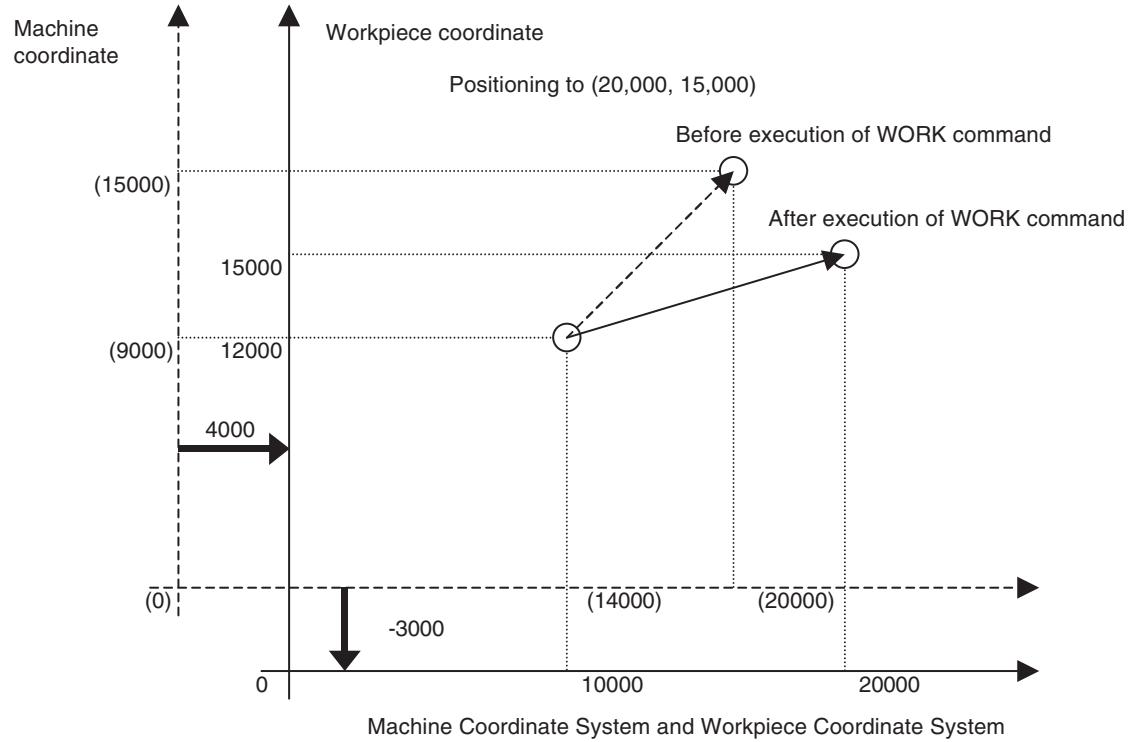
Basics
- Offset for the workpiece coordinate system is set when the OFFPOS command is executed, and it is switched to the workpiece coordinate system by executing WORK command.
- Offset value (offset amount set by OFFPOS command) is the data for each axis. It has nothing to do with either motion programs or motion tasks.
- The coordinate system select (coordinate system type and No. that have been set by ORIGIN/ WORK command) is the data for each motion program. It has nothing to do with axes or motion tasks.
| Starting a New Program Operation | If a new main program is started (the first execution after power is turned ON, or execution in the Start Mode = 0 or 3), the machine coordinate system is always used. Although the offset value is inherited from the previous program, the coordinate system select is not inherited. |
| Calling Sub-Program | When a sub-program is called, the offset value and coordinate system select are inherited to the sub-program. |
| When returning to the main program from the sub-program, all the modal data is inherited. | |
| Parallel Branching | If parallel branching has been executed using the PARALLEL command, the offset value and coordinate system select for all the branches are inherited. The offset value and coordinate system select that have been changed in a branch will affect other branches as well. |
| Executing End Command | If a program is ended using the END command, neither the offset value nor coordinate system select are initialized. |
6-2 Command Overview
6-2-1 Command List
There are two types of commands for the MC Unit.
- Single Execution Command:
In a motion task, two or more commands of this type cannot be executed together in one scan. It can be executed simultaneously, however, with multiple execution commands or with another single execution command in another branch of parallel branches.
Commands related to movement are usually of this type.
- Multiple Execution Command:
In a motion task, several commands of this type can be executed together in one scan. It can be executed simultaneously with a single execution command or other multiple execution commands in the same scan.
Commands related to operation (arithmetic, logical, etc.) are usually of this type.
The meanings of the symbols in the motion task column are as follows:
| Symbol | Meaning |
| S | Single Execution Command |
| M | Multiple Execution Command |
| x | Not executed as an independent command (no type). |
Commands that can be used in the motion program are listed below:
| Classifica- tion | Command/func- tion name | Code | Applicable task | Summary | Completion condi- tion (Proceed to next block) |
| Motion | |||||
| Axis move- ment | POSITIONING | MOVE | @ S | Moves each axis independently. | In-position |
| LINEAR INTERPO- LATION | MOVEL | @ S | Moves axes with linear interpola- tion. | Travel distance out- put completed. | |
| CIRCULAR INTER- POLATION | MOVEC | @ S | Moves axes with circular interpola- tion. | Travel distance out- put completed. | |
| ORIGIN SEARCH | DATUM | @ S | Finds machine origin according to input signals. | In-position | |
| INTERRUPT FEED- ING | MOVEI | @ S | Changes target position by means of input signals. | In-position | |
| TIME-SPECIFIED POSITIONING | MOVET | @ S | Performs positioning with speci- fied time period. | In-position | |
| TRVERSE | MOVETRAV | @ S | Executes winding (traverse) function of winder. | Travel distance out- put completed. | |
| ELECTRONIC CAM, SINGLE AXIS | CAM | @ S | Executes cam operation accord- ing to cam table. | In-position | |
| Axis opera- tion | LINK OPERATION | MOVELINK | @ S | Synchronizes the slave to the master based on travel distance of the master in acceleration and deceleration. | Depends on the link option. |
| ELECTRONIC CAM, SYNCHRONOUS | CAMBOX | @ S | Executes cam operation accord- ing to cam table and master axis. | Depends on the link option. | |
| ELECTRONIC SHAFT | CONNECT | @ S | Synchronizes the slave to the master in a fixed ratio to the master axis. | Synchronization established. | |
| TRAILING SYN- CHRONIZATION | SYNC | @ S | Executes trailing + synchronizes the slave to the master axis. | Synchronization established. | |
| TRAVEL DISTANCE SUPERIMPOSE | ADDAX | @ S | Superimposes travel distance between axes. | Synchronization established. | |
| SPEED CONTROL | SPEED | @ S | Outputs speed commands. | Specified speed reached. | |
| TORQUE CON- TROL | TORQUE | @ S | Outputs torque commands. | Specified torque reached. | |
| Axis opera- tion cancel | SYNCHRONIZING END | SYNCR | @ S | Cancels MOVELINK, CAMBOX, CONNECT, or SYNC. | In-position |
| TRAVEL AMOUNT SUPERIMPOSE CANCEL | ADDAXR | @ S | Cancels travel distance superim- pose. | Synchronization can- celled. | |
| SPEED CONTROL CANCEL | SPEEDDR | @ S | Cancels speed control | Switch to position control mode com- pleted | |
| TORQUE CON- TROL CANCEL | TORQUER | @ S | Cancels torque control | Switch to position control mode com- pleted | |
| Classification | Command/func-tion name | Code | Applicable task | Summary | Completion condi-tion (Proceed to next block) |
| Motion | |||||
| Settings | TARGET POSITION CHANGE | MOVEMODI | @ M | Changes target position of an operating axis. | Target position change completed. |
| ABSOLUTE SPECI-FICATION | ABL | @ M | Treats coordinate values as absolute values. | Coordinate mode changed. | |
| INIncrementAL SPECIFICATION | INC | @ M | Treats coordinate values as incremental values. | Coordinate mode changed. | |
| CHANGE PARAMETER VALUE | PARAM | @ S | Temporarily changes parameter values. | Parameter change completed. | |
| PASS MODE | PASSMODE | @ M | Connects interpolation blocks smoothly. | Mode change com-pleted. | |
| STOP MODE | STOPMODE | @ M | Waits for in-position in each interpolation block. | Mode change com-pleted. | |
| MACHINE COORDI-NATE SYSTEM SELECT | ORIGIN | @ S | Sets coordinate system to machine coordinate system. | Coordinate system change completed. | |
| WORKPIECE COORDINATE SYS-TEM SELECT | WORK | @ S | Sets coordinate system to work-piece coordinate system. | Coordinate system change completed. | |
| WORKPIECE COORDINATE SYS-TEM OFFSET CHANGE | OFFPOS | @ M | Changes workpiece coordinate system offset values. | Offset value change completed. | |
| PRESENT POSI-TION LATCH | LATCH | @ S | Latches the present position. | Latch request recep-tion completed. | |
| SINGLE BLOCK IgnORED | NSTOP | @ X | Ignores single block mode. | --- | |
| Classifica-tion | Command/func-tion name | Code | Applicable task | Summary | Completion condi-tion (Proceed to next block) |
| Motion | |||||
| Control | PROGRAM START | PROG | @ M | Indicates the start of program. | Program start pro-cessing completed. |
| PROGRAM END | END | @ S | Indicates the end of program. | Program end pro-cessing completed. | |
| SUB-PROGRAM CALL | GOSUB | @ S | Calls sub-programs. | Sub-program call completed. | |
| SUB-PROGRAM END | RETURN | @ S | Ends sub-program, and returns to point where sub-program was called. | Return completed. | |
| DWELL TIME | DWELL | @ S | Waits for specified period of time, and then executes next block. | Dwell time elapsed. | |
| WAIT FOR CONDI-TION TO BE MET | WAIT | @ M | Waits for condition to be satisfied and executes the next block. | Condition satisfied. | |
| OPTIONAL END | STOPOP | @ S | Aborts next block when condition is satisfied. | Condition setting completed. | |
| CONDITIONAL BRANCHING | IF | @ M | Branches depending on condi-tions. | Condition check completed. | |
| ELS | @ M | --- | |||
| ENDIF | @ M | No block being exe-cuted. | |||
| REPEAT WHILE | WHILE | @ M | Repeats until a given condition is satisfied. | Condition check completed. | |
| WEND | @ M | No block being exe-cuted. | |||
| REPEAT FOR | FOR | @ M | Repeats for a given number of times (variable, constant, or immediate value). | Condition check completed. | |
| NEXT | @ M | No block being exe-cuted. | |||
| PARALLEL EXECU-TION | PARALLEL | @ S | Executes specified sections in parallel. | --- | |
| JOINT | @ S | No block being exe-cuted (in branch). | |||
| JWAIT | @ S | All JOINT execution completed. | |||
| SELECTIVE EXECUTION | SWITCH | @ M | Executes specified sections selectively depending on condi-tions. | Condition check completed. | |
| CASE | @ M | --- | |||
| BREAK | @ M | No block being exe-cuted. | |||
| DEFAULT | @ M | --- | |||
| SEND | @ M | No block being exe-cuted. | |||
| NO OPERATION(SINGLE) | NOPS | @ S | No operation (as a single execu-tion command). | --- | |
| NO OPERATION(MULTIPLE) | NOPM | @ M | No operation (as a multiple execu-tion command). | --- | |
| Classification | Command/func-tion name | Code | Applicable task | Summary | Completion condi-tion (Proceed to next block) |
| Motion | |||||
| Simple arithmetic operations | ASSIGN | = | @ M | Assigns values to variables. | Result assigned. |
| ADD | + | @ x | Performs addition. | Result assigned. | |
| SUBTRACT | - | @ x | Performs subtraction. | Result assigned. | |
| MULTIPLY | * | @ x | Performs multiplication | Result assigned. | |
| DIVIDE | / | @ x | Performs division. | Result assigned. | |
| REMAINDER | % | @ x | Finds the remainder of a division operation. | Result assigned. | |
| EXPONENT | ^ | @ x | Applies exponents. | Result assigned. | |
| Logic operations | OR (LOGICAL OR) | | | @ x | Calculates logical OR. | Result assigned. |
| XOR (LOGICAL EXCLUSIVE OR) | ~ | @ x | Calculates logical exclusive OR. | Result assigned. | |
| AND (LOGICAL AND) | & | @ x | Calculates logical AND. | Result assigned. | |
| NOT (REVERSE) | ! | @ x | Reverses bits. | Result assigned. | |
| Functions | ABSOLUTE VALUE | ABS | @ x | Finds the absolute value. | Result assigned. |
| SINE | SIN | @ x | Finds the sine. | Result assigned. | |
| COSINE | COS | @ x | Finds the cosine. | Result assigned. | |
| TANGENT | TAN | @ x | Finds the tangent. | Result assigned. | |
| ARC SINE | ASIN | @ x | Finds the arc sine. | Result assigned. | |
| ARC COSINE | ACOS | @ x | Finds the arc cosine. | Result assigned. | |
| ARC TANGENT | ATAN | @ x | Finds the arc tangent. | Result assigned. | |
| SQUARE ROOT | SQR | @ x | Finds the square root. | Result assigned. | |
| EXPONENT | EXP | @ x | Finds the exponent. | Result assigned. | |
| NATURAL LOGA-RITHM | LOG | @ x | Finds the natural logarithm. | Result assigned. | |
| DECIMAL | FRAC | @ x | Finds the decimal portion. | Result assigned. | |
| SIGN | SGN | @ x | Returns 1 for 0 or greater, and -1 for negative values. | Result assigned. | |
| Bit operations | SPECIFIED BIT ON | SET | @ x | Turns ON specified bits. | Bit operation com-pleted. |
| SPECIFIED BIT OFF | RESET | @ x | Turns OFF specified bits. | Bit operation com-pleted. | |
| SHIFT RIGHT | SFTR | @ M | Shifts to right for specified amount. | Shift completed. | |
| SHIFT LEFT | SFTL | @ M | Shifts to left for specified amount. | Shift completed. | |
| Data operations | BCD-TO-BIN | BIN | @ x | Converts BCD data to BIN data. | Result assigned. |
| BIN-TO-BCD | BCD | @ x | Converts BIN data to BCD data. | Result assigned. | |
| BLOCK TRANSFER | XFER | @ M | Transfers data block. | All data transferred. | |
| CLEAR | CLEAR | @ M | Clears data block to zero. | All data cleared. |
6-2-2 Command Format
The following notation is used for the format.
| Symbol | Meaning |
| <> | Indicates the content, data |
| { } | Optional operand, omissionle |
| ---N--- | The operand that can be specified up to the number shown. |
| - | Required en quad |
| Classifica-tion | Name | Format | |
| Axis move-ment | Positioning | MOVE_<!--axis name>]<position command value>---8---- | |
| Linear interpolation | MOVEL_<!--axis name>]<position command value>---8----{F<Interpolation feed rate>}; | ||
| Circular interpolation | Center position specification:MOVEC_Q<rotation direction><horizontal axis name><horizontal axis position command value><vertical axis name><vertical axis position command value>I<horizontal axis center command>J<vertical axis center command>{[linear axis name]<linear axis command value}{L<number of turns}{F<interpolation feed rate>};Radius specification:MOVEC_Q<rotation direction><horizontal axis name><horizontal axis position command value><vertical axis name><vertical axis position command value>R<radius>{[linear axis name]><linear axis command value>} {F<interpolation feed rate>};Origin search | {[linear axis name]><linear axis command value>} {F<interpolation feed rate>}; | |
| Interrupt feeding | DATUM_<!--axis name>]<offset value>---8----; | ||
| Time-specified posi-tioning | MOVEI_<!--axis name>]<position command value>D<fixed feed amount>V<speed after signal input>; | ||
| Traverse | MOVET_<!--axis name>]<position command value>---8----T<positioning time>; | ||
| Electronic cam, sin-gle axis | MOVETRAV_Q<operating mode><winding axis name><winding axis rotations>[traverse axis name]<traverse axis winding width>L<number of layers>[rotations at starting edge] {J<rotations at ending edge}> {F<winding axis speed>}; | ||
| CAM_<!--axis name><Cam table number>K<displacement data multiplier>T<execu-tion time> {S<starting data number}> {E<ending data number>}; | |||
| Axis oper-a-tion | Link operation | MOVELINK_<!--slave axis name><slave axis travel distance><master axis name><master axis travel distance in acceleration>D<master axis travel distance in deceleration>Q<link option> {l<link start position} {B<master axis classification>}; | |
| Electronic cam, syn-chronous | CAMBOX_<!--slave axis name><Cam table number><master axis name><link dis-tance>K<displacement data multiplier> {S<starting data number}> {E<ending data number}> {Q<link option}> {l<link start position} {B<master axis classification>}; | ||
| Electronic shaft | CONNECT_<!--slave axis name><gear ratio numerator>---8----<master axis name><gear ratio denominator> {B<master axis classification>}; | ||
| Trailing synchroniza-tion | SYNC_<!--slave axis name><catch-up position offset><master axis name><marker sensor ON position> {B<master axis classification>}; | ||
| Travel distance superimpose | ADDAX_<!--slave axis name><master axis name> {B<master axis classification>}; | ||
| Speed control | SPEED_<!--axis name><speed command value>---8----T<speed change rate>; | ||
| Torque control | TORQUE_<!--axis name><torque command value>---8----T<torque change rate>; | ||
| Axis oper-a-tion cancel | Synchronization can-cel | SYNCR_<!--slave axis name><travel distance for deceleration stop>---8----; | |
| Travel distance superimpose cancel | ADDAXR_<!--slave axis name>---8----); | ||
| Speed control cancel | SPEEDR_<!--axis name>---8---- T<speed change rate>; | ||
| Torque control can-cel | TORQUER_<!--axis name>---8---- T<torque change rate>; | ||
| Classification | Name | Format | |
| Setting | Target position change | MOVEMODI_[<axis name>]<changed target position>---8----; | |
| Absolute specifica-tion | ABL; ABL_<other command>; | ||
| Incremental specifi-cation | INC; INC_<other command>; | ||
| Parameter value set-ting | PARAM_P<parameter number> = <parameter setting value>; PARAM [<axis name>]<servo parameter number> = <parameter setting value>; | ||
| Pass Mode | PASSMODE; | ||
| Stop Mode | STOPMODE; | ||
| Machine coordinate system select | ORIGIN; | ||
| Workpiece coordi-nate system select | WORK_C<workpiece coordinate system number>; | ||
| Workpiece coordi-nate system offset change | OFFPOS_C<workpiece coordinate system number>[<axis name>] <workpiece coordinate system offset amount>---8----; | ||
| Present position latch | LATCH_[<axis name>]<latch position storing variable>{l<latch check start position}{J<latch check end position.}; | ||
| Single block ignored | NSTOP_<other command>; | ||
| Control | Program start | PROG_P<program number> Q<axis declaration>; | |
| Program end | END; | ||
| Sub-program call | GOSUB_P<sub><sub>sub-program number</sub>;<br> | ||
| Sub-program End | RETURN; | ||
| Dwell time | DWELL_T<dwell time>; | ||
| Wait for condition to be met | WAIT<conditional expression>; | ||
| Optional end | STOPOP<conditional expression>; | ||
| Conditional branching | IF<conditional expression>; | ||
| <processing 1> | |||
| {ELSE; | |||
| <processing 2>} | |||
| ENDIF; | |||
| Repeat WHILE | WHILE<conditional expression>; | ||
| <processing> | |||
| WEND; | |||
| Repeat FOR | FOR_W<work register for repeat count> L<repeat end value>S<number of increment steps>; | ||
| <processing> | |||
| NEXT; | |||
| Parallel execution | PARALLEL_N<number of branches>; | ||
| <processing 1> | |||
| {JOINT; | |||
| --- | |||
| <processing N>} | |||
| JWAIT; | |||
| Selective execution | SWITCH<conditional variable>; | ||
| {CASE<conditional constant>; | |||
| <processing 1> | |||
| BREAK; | |||
| ---} | |||
| {DEFAULT;} | |||
| <processing N> | |||
| SEND; | |||
| No operation (single) | NOPS; | ||
| No operation (multi-ple) | NOPM; | ||
| Simple arithmetic operation | Assign | <variable> = <numerical value>; | |
| Add | <variable> = <numerical value>+</numerical value>; | ||
| Subtract | <variable> = <numerical value>--<numerical value>; | ||
| Multiply | <variable> = <numerical value>*<numerical value>; | ||
| Divide | <variable> = <numerical value>/<numerical value>; | ||
| Reminder | <variable> = <numerical value%<numerical value>; | ||
| Exponent | <variable> = <numerical value^<numerical value>; | ||
| Logic operation | OR (logical OR) | <variable> = <numerical value| <numerical value>; | |
| XOR (logical exclusive OR) | <variable> = <numerical value> ~ < numerical value>; | ||
| AND (logical AND) | <variable> = <numerical value> & <numerical value>; | ||
| NOT (reverse) | <variable> = <numerical value> != <numerical value>; | ||
| Classifica- tion | Name | Format | |
| Functions | Absolute value | <variable> = ABS<numerical value>; | |
| Sine | <variable> = SIN<numerical value>; | ||
| Cosine | <variable> = COS<numerical value>; | ||
| Tangent | <variable> = TAN<numerical value>; | ||
| ARC Sine | <variable> = ASINE<numerical value>; | ||
| ARC Cosine | <variable> = ACOS<numerical value>; | ||
| ARC Tangent | <variable> = ATAN<numerical value>; | ||
| Square root | <variable> = SQR<numerical value>; | ||
| Exponent | <variable> = EXP<numerical value>; | ||
| Natural logarithm | <variable> = LOG<numerical value>; | ||
| Decimal | <variable> = FRAC<numerical value>; | ||
| Sign | <variable> = SGN<numerical value>; | ||
| Bit oper- tions | Specified bit ON | <variable> = SET<logic operation expression>; | |
| Specified bit OFF | <variable> = RESET<logic operation expression>; | ||
| Shift right | SFTR<shift object variable>_N<shift amount>; | ||
| Shift left | SFTL<shift object variable>_N<shift amount>; | ||
| Data oper- tions | BCD→BIN | <variable> = BIN<numerical value>; | |
| BIN→BCD | <variable> = BCD<numerical value>; | ||
| Block transfer | XFER<transfer source first data>_<transfer destination first data>_N<number of transferred data>; | ||
| Clear | CLEAR<first cleared data>_N<number of cleared data>; | ||
6-2-3 Command List (Operand List)
The following table describes the operands that are used in commands.
| Operand | Command: Meaning of the value | Remark |
| Axis name | MOVE: Position command value | These operands require distinction of axis names. |
| MOVEL: Position command value | ||
| MOVEC: Position command value | ||
| DATUM: Origin offset | ||
| MOVEI: Position command value | ||
| MOVET: Position command value | ||
| MOVETRAV: Winding axis rotations | ||
| MOVETRAV: Traverse axis winding width | ||
| MOVELINK: Slave axis travel distance | ||
| MOVELINK: Master axis travel distance | ||
| CAM: Cam table number | ||
| CAMBOX: Cam table number | ||
| CAMBOX: Master axis linking distance | ||
| CONNECT: Gear ratio numerator | ||
| CONNECT: Gear ratio denominator | ||
| SYNCR: Travel distance for deceleration stop | ||
| ADDAX: <No numerical value specified> | ||
| SYNC: Catch-up position offset | ||
| SYNC: Marker sensor ON position | ||
| SPEED: Specified speed | ||
| SPEEDR: <No numerical value specified> | ||
| TORQUE: Specified torque | ||
| TORQUER: <No numerical value specified> | ||
| MOVEMODI: Changed target position | ||
| PARAM: Servo parameter number | ||
| OFFPOS: Workpiece coordinate system offset amount | ||
| LATCH: Latch position storing variable | ||
| A | MOVELINK: Master axis travel distance at acceleration | Travel distance at acceleration. |
| B | MOVELINK: Master axis classification | Indicates the master axis classification in syn-chronization. |
| CAMBOX: Master axis classification | ||
| CONNECT: Master axis classification | ||
| SYNC: Master axis classification | ||
| ADDAX: Master axis classification | ||
| C | WORK: Workpiece coordinate system number | Indicates coordinate system number. |
| OFFPOS: Workpiece coordinate system number | ||
| D | MOVEL: Fixed feed amount | Indicates the travel distance for deceleration and incremental travel distance. |
| MOVELINK: Master axis travel distance at deceleration | ||
| E | CAM: Ending data number | Indicates the ending data number. |
| CAMBOX: Ending data number | ||
| F | MOVEL: Interpolation feed rate | Indicates interpolation feed rate. |
| MOVEC: Interpolation feed rate | ||
| MOVETRAV: Winding axis speed | ||
| I | MOVEC: Horizontal axis center position | Indicates the first auxiliary position command. |
| MOVETRAV: Rotations at starting edge | ||
| MOVELINK: Link start position | ||
| CAMBOX: Link start position | ||
| LATCH: Latch check start position | ||
| J | MOVEC: Vertical axis center position | Indicates the second auxiliary position com-mand. |
| MOVETRAV: Rotations at ending edge | ||
| LATCH: Latch check end position | ||
| K | CAM: Displacement data multiplier | Indicates coefficient like multiplier. |
| CAMBOX: Displacement data multiplier | ||
| L | MOVEC: Number of turns | Indicates the number of repetitions. |
| MOVETRAV: Number of layers | ||
| FOR: Repeat end value | ||
| N | PARALLEL: Number of branches | Indicates numerical values. |
| SFTR: Shift amount | ||
| SFTL: Shift amount | ||
| XFER: Number of transferred data | ||
| CLEAR: Number of cleared data | ||
| P | PARAM: Parameter number = parameter setting value | Indicates the parameter number and program number. |
| PROG: Program number | ||
| GOSUB: Sub-program number | ||
| Q | MOVEC: Rotation direction specification | Indicates option items. |
| MOVETRAV: Operating mode | ||
| MOVELINK: Link option | ||
| CAMBOX: Link option | ||
| PROG: Axis declaration | ||
| R | MOVEC: Radius | Indicates radius. |
| S | CAM: Starting data number | Indicates the start number and number of steps. |
| CAMBOX: Starting data number | ||
| FOR: Number of increment steps | ||
| T | MOVET: Positioning time | Indicates various times. |
| CAM: Execution time | ||
| SPEED: Speed change rate | ||
| SPEEDR: Speed change rate | ||
| TORQUE: Torque change rate | ||
| TORQUER: Torque change rate | ||
| DWELL: Dwell time | ||
| V | MOVEI: Speed after signal input | Indicates axis feed rate. |
| W | FOR: Work register for repeat count | Indicates work register. |
| Expression | WAIT: Conditional expression | Indicates expressions |
| STOPOP: Conditional expression | ||
| IF: Conditional expression | ||
| WHILE: Conditional expression | ||
| Variables, Constants | SWITCH: Conditional variable | Each variable and constant have specific mean-ing. |
| CASE: Conditional constant | ||
| Various operational commands: Various |
6-2-4 Program Number and Axis Declaration
The program number and axes to be used in the program are specified in PROG command (Program Start). Refer to Program Start (PROG) on page 347.
Format
PROG_P
Program Number
The table below shows the relations between the program number and main program/sub-program for motion tasks.
| Program No. | Program |
| 0000-0499 | Main program for motion tasks |
| 0500-0999 | Sub-program for motion tasks |
Axis Declaration
In "Axis Declaration", axes to be used in the program are specified with the bit train (32-bit) in hexadecimal corresponding to the physical axis numbers.
Program Example
When using the physical axes (numbers J02, J03, J04, J12, and J14) in the motion task main program "0000", the bit train for the axes to be used will be as shown below:

Therefore, in the PROG command, the following description is used: PROG P000 Q0000280E;
6-2-5 Default Mode and Coordinate System
Various modes and coordinate systems can be used when executing commands.
The following table shows the default settings for these.
| Coordinate system | General description | |
| Coordinate system | Machine coordinate system | Positioning is performed on the reference (machine) coordinate system (Default setting) |
| Workpiece coordinate system | Positioning is performed on the workpiece coordinate system. | |
| Travel distance specification | Absolute specification | Positioning is performed with absolute positions. (Default setting) |
| Incremental specification | Positioning is performed with relative positions. | |
| Operating mode | Stop Mode | For interpolation operations, the next operation is performed only after positioning is completed. (Default setting) |
| Pass Mode | For interpolation operations, the next operation is performed without waiting for positioning to be completed. | |
6-3 Command Details
6-3-1 Expression in This Section
This section provides detailed descriptions of the commands. Command formats, operands and application are described and programming examples are provided.
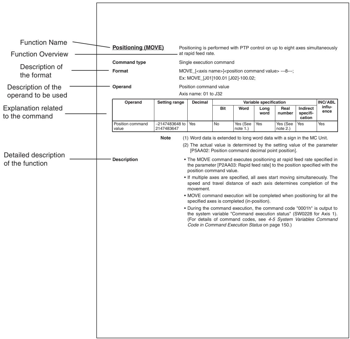
The following notation is used for the format.
| Note | Description |
| <> | Indicates the content, data |
| { } | Optional operand, omissionle |
| ---N--- | The operand that can be specified up to the number shown. |
| _ | Required en quad |
6-3-2 Axis Movement
This section describes the details of each command.
Positioning (MOVE)
Positioning is performed with PTP control on up to eight axes simultaneously at rapid feed rate.
Command type
Single execution command
Format
MOVE_[
Ex: MOVE_[J01]100.01 [J02]-100.02;
Operand
Position command value
Axis name: 01 to J32
| Operand | Setting range | Decimal | Variable specification | INC/ABL influence | ||||
| Bit | Word | Long word | Real number | Indirect specification | ||||
| Position command value | -2147483648 to 2147483647 | Yes | No | Yes (See note 1.) | Yes | Yes (See note 2.) | Yes | Yes |
Note
(1) Word data is extended to long word data with a sign in the MC Unit.
(2) The actual value is determined by the setting value of the parameter [P5AA02: Position command decimal point position].
Description
- The MOVE command executes positioning at rapid feed rate specified in the parameter [P2AA03: Rapid feed rate] to the position specified with the position command value.
- If multiple axes are specified, all axes start moving simultaneously. The speed and travel distance of each axis determines completion of the movement.
- MOVE command execution will be completed when positioning for all the specified axes is completed (in-position).
- During the command execution, the command code "0001h" is output to the system variable "Command execution status" (SW0228 for Axis 1). (For details of command codes, see 4-5 System Variables Command Code in Command Execution Status on page 158.)
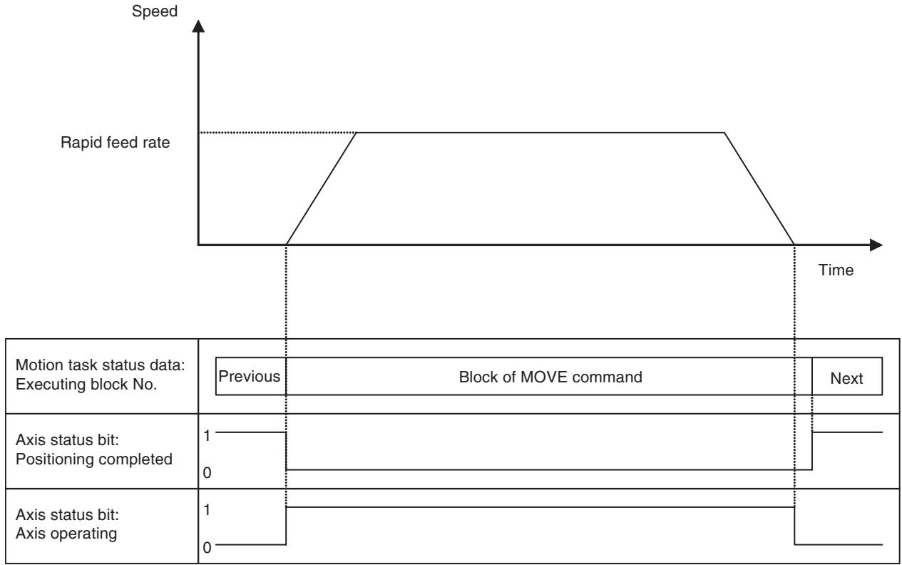
Linear Interpolation (MOVEL)
Positioning is performed on up to eight axes with linear interpolation at the specified interpolation feed rate.
Command type
Single execution command
Format
MOVEL_[
Ex: MOVEL_[J01]100.01 [J02]-100.02 F10000.25;
Operand
Position command value
Axis name: J01 to J32
| Operand | Setting range | Decimal | Variable specification | INC/ABL influ- ence | ||||
| Bit | Word | Long word | Real number | Indirect specifi- cation | ||||
| Position command value | -2147483648 to 2147483647 | Yes | No | Yes (See note 1.) | Yes | Yes (See note 2.) | Yes | Yes |
| Interpolation feed rate | 1 to 2147483647 (See note 3.) | Yes | No | Yes (See note 1.) | Yes | Yes (See note 4.) | Yes | No |
Note
(1) Word data is extended to long word data with a sign in the MC Unit.
(2) The actual value is determined by the setting value of the parameter [P5AA02: Position command decimal point position].
(3) The maximum speed in actual operations will be limited by the maximum feed rate of the interpolation or axis.
(4) The actual value is determined by the setting value of the parameter [P00M10: Interpolation feed decimal point position].
Description
- The MOVEL command executes linear interpolation at the specified interpolation feed rate to the position specified with the position command value.
- The interpolation feed rate indicates the combined speed of all the specified axes.
- The MOVEL command execution will be completed when the travel distance command output for all the specified axes is completed (or No.2 in-position completion).
- During the command execution, the command code "0002h" is output to the system variable "Command execution status" (SW0228 for Axis 1). (For details of command codes, see 4-5 System Variables Command Code in Command Execution Status on page 158.)
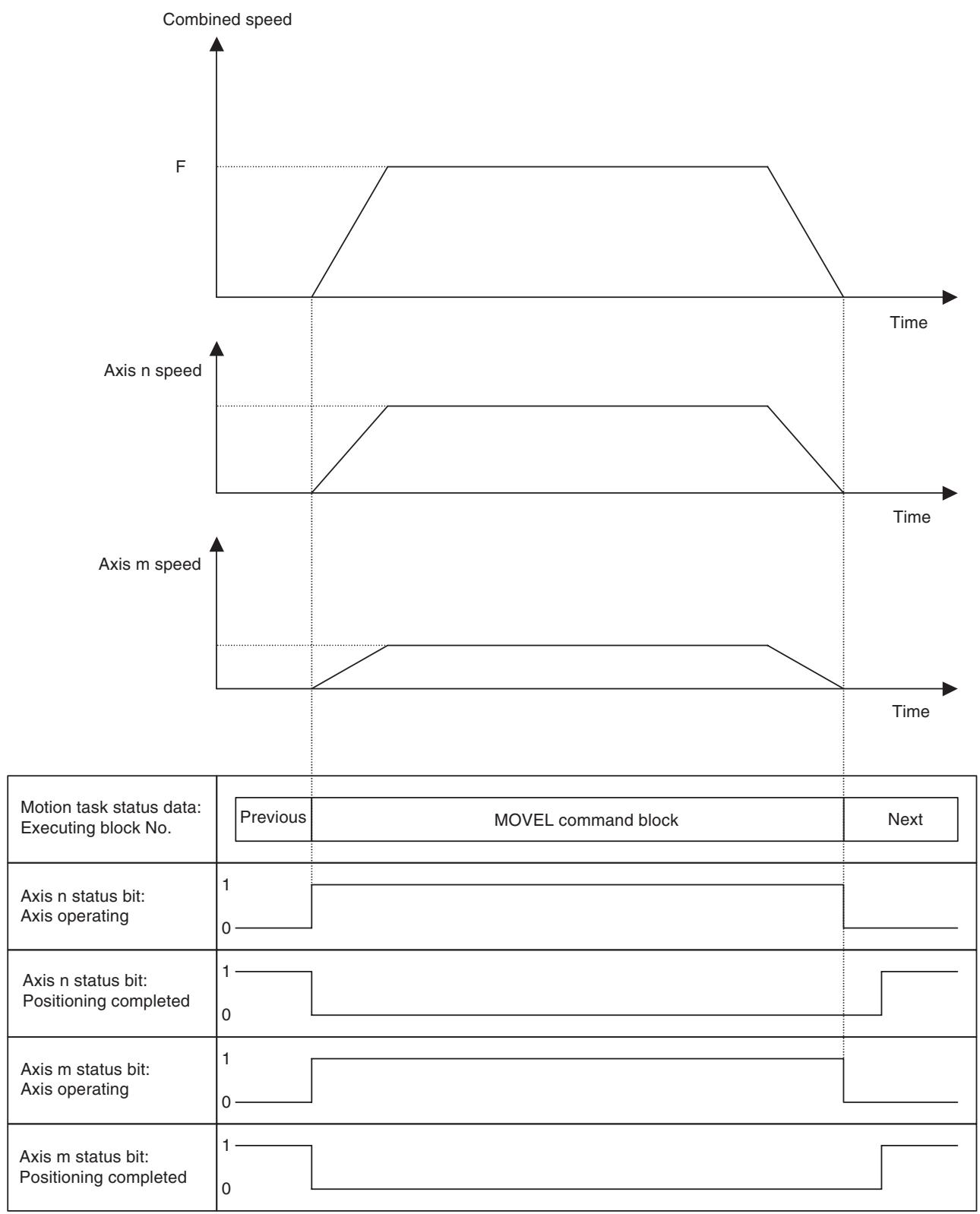
Circular Interpolation (MOVEC)
This command executes positioning with circular interpolation on two axes at specified interpolation feed rate. Moreover, positioning with helical circular interpolation (2-axis circular interpolation + 1-axis linear interpolation) can be performed. Specifying the number of turns for helical circular interpolation can realize winding operation with multi-turns.
Command type
Single execution command
Format
Center position specification:
MOVEC_Q
[
I
{[
Radius specification:
MOVEC_Q
[ \text{[
Ex: Center position specification: MOVEC_Q1 [J01]100.00 [J02]200.00 I0 J0 F20000.00; Radius specification: MOVEC_Q1 [J01]100.00 [J02]200.00 R50.00 F20000.00;
Operand
Center position specification
Axis name: J01 to J32
| Operand | Setting range | Decimal | Variable specification | INC/ABL influence | ||||
| Bit | Word | Long word | Real number | Indirect specifi-cation | ||||
| Rotation direction | 1, -1 | No | No | Yes (See note 1.) | Yes | Yes (See note 2.) | Yes | No |
| Horizontal axis posi-tion command value | -2147483648 to 2147483647 | Yes | No | Yes (See note 1.) | Yes | Yes (See note 3.) | Yes | Yes |
| Vertical axis position command value | -2147483648 to 2147483647 | Yes | No | Yes (See note 1.) | Yes | Yes (See note 3.) | Yes | Yes |
| Horizontal axis cen-ter command | -2147483648 to 2147483647 | Yes | No | Yes (See note 1.) | Yes | Yes (See note 3.) | Yes | See note 5. |
| Vertical axis center command | -2147483648 to 2147483647 | Yes | No | Yes (See note 1.) | Yes | Yes (See note 3.) | Yes | See note 5. |
| Linear axis com-mand value | -2147483648 to 2147483647 | Yes | No | Yes (See note 1.) | Yes | Yes (See note 3.) | Yes | Yes |
| Number of turns | 1 to 2147483647/2πr-1 (Figures below decimal point to be omitted) | No | No | Yes (See note 1.) | Yes | Yes (See note 2.) | Yes | No |
| Interpolation feed rate | 1 to 2147483647 | Yes | No | Yes (See note 1.) | Yes | Yes (See note 4.) | Yes | No |
Note
(1) Word data is extended to long word data with a sign in the MC Unit.
(2) Figures below the decimal point are to be omitted.
(3) The actual value is determined by the setting value of the parameter [P5AA02: Position command decimal point position].
(4) The actual value is determined by the setting value of the parameter [P00M10: Interpolation feed decimal point position].
(5) When P00004 bit01 = 0 (ABL specification disable), there is no influence and INC specification is always used.
Radius Specification
Axis name: J01 to J32
| Operand | Setting range | Decimal | Variable specification | INC/ABL influence | ||||
| Bit | Word | Long word | Real number | Indirect specification | ||||
| Rotation direction | 1, -1 | No | No | Yes (See note 1.) | Yes | Yes (See note 2.) | Yes | No |
| Horizontal axis position command value | -2147483648 to 2147483647 | Yes | No | Yes (See note 1.) | Yes | Yes (See note 3.) | Yes | Yes |
| Vertical axis position command value | -2147483648 to 2147483647 | Yes | No | Yes (See note 1.) | Yes | Yes (See note 3.) | Yes | Yes |
| Radius | -2147483648 to 2147483647 | Yes | No | Yes (See note 1.) | Yes | Yes (See note 3.) | Yes | Yes |
| Linear axis command value | -2147483648 to 2147483647 | Yes | No | Yes (See note 1.) | Yes | Yes (See note 3.) | Yes | Yes |
| Interpolation feed rate | 1 to 2147483647 | Yes | No | Yes (See note 1.) | Yes | Yes (See note 4.) | Yes | No |
Note
(1) Word data is extended to long word data with a sign in the MC Unit.
(2) Figures below the decimal point are to be omitted.
(3) The actual value is determined by the setting value of the parameter [P5AA02: Position command decimal point position].
(4) The actual value is determined by the setting value of the parameter [P00M10: Interpolation feed decimal point position].
Description
- The MOVEC command executes positioning with circular interpolation at the speed specified with [interpolation feed rate] to the position specified by [horizontal axis position command value] and [vertical axis position command value].
- The rotation direction is clockwise when Q = 1 , and counter-clockwise when Q = -1 .
- The circular arc center and radius are specified either by the center value or by the radius value.
- For the center position specification, [horizontal axis center command] and [the vertical axis center command] are handled as shown below by the parameter [P00004.bit01: Circular arc interpolation center position].
| P00004.01 | Handling of I/J |
| 0: (ABL specification disabled) | The value in I or J is always treated as the travel distance from the present position. |
| 1: (ABL specification enabled) | The value in I or J is treated as travel distance from spec-ified position or present position depending on ABL/INC specification. |
- When specifying the radius, [radius] is always treated as the distance to be moved from the present position.
- The unit system of the horizontal axis is used for the radius.
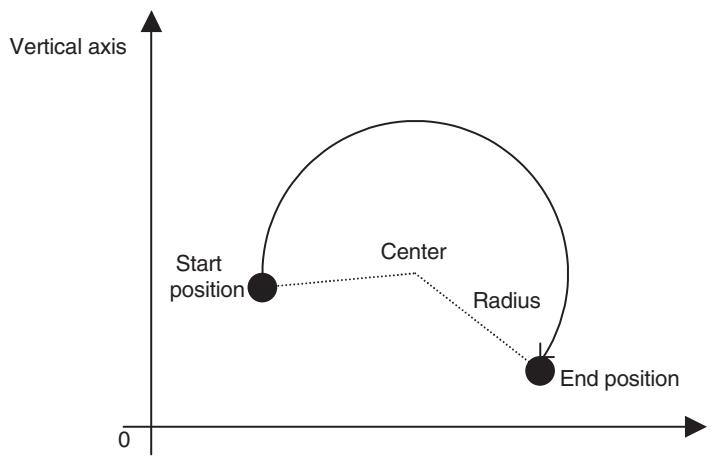
Horizontal axis
- When [Number of turns] is specified, multiple rotations will occur. In addition, multiple rotations can be specified only for center position specification. For radius specification, programs cannot be loaded (because the center position cannot be determined If the start position = the end position for radius specification.)
- The number of rotations excluding the circular arc from the start point to the end point is specified for [Number of turns]. When the start position is not equal to the end position, the travel distance per block will be circular arc of [Number of turns] + a. When the start position is equal to the end position, the travel distance per block will be circular arc of [Number of turns] + 1.
- If [Linear axis name] and [Linear axis command value] are added, helical circular interpolation can be realized. If [Number of turns] is specified to realize multiple rotations for helical circular interpolation, the end position has to be specified.
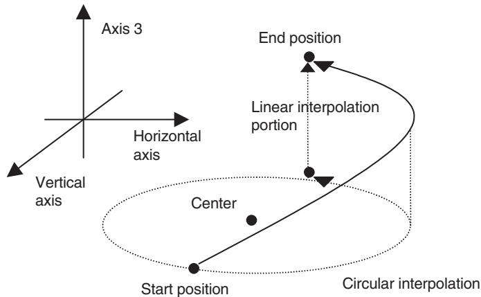
- [Interpolation feed rate] is handled as shown in the table below depending on the interpolation type and the setting of the parameter [P00004.bit00: Helical circular interpolation speed].
| Interpolation type | P00004.00 | Interpolation feed rate |
| Circular interpolation | 0 or 1 | Combined speed of the horizontal and vertical axes |
| Helical circular interpolation | 0 (speed on the circumference) | Combined speed of the horizontal and vertical axes |
| Helical circular interpolation | 1 (speed on the tangent) | Combined speed of the horizontal, vertical, and linear axes. |
- In radius specification, if [Radius] is positive, the center angle will be 180 degrees or smaller. If [Radius] is negative, the center angle will be 180 degrees or greater.
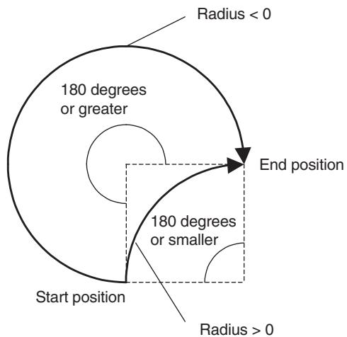
- MOVEC command execution will be completed (or No.2 in-position complete) when the travel distance command output for all specified axes is completed.
- During the command execution, the command code "0003h" is output to the system variable "Command execution status" (SW0228 for Axis 1). (For details of command codes, see 4-5 System Variables Command Code in Command Execution Status on page 158.)
- When a circular arc cannot be drawn with the specified radius or center position, the radius is compensated to draw the arc. Having the radius in radius specification or the radius calculated with center specification as the initial value, the radius is increased to accomplish the radius at the end position along the rotating angle.
- When executing circular interpolation on the axis with S-curve filter setting, an arc larger than the specified arc may be drawn. The greater the S-curve time constant is, the greater the overshoot amount (= Specified arc - Actual arc) will be. Operate only after thorough adjustment is made.
Origin Search (DATUM)
The DATUM command performs an origin search for the specified axis.
Command type
Single execution command
Format
DATUM_[
Ex: DATUM_[J01]0 [J02]0;
Operand
Axis name: J01 to J32
| Operand | Setting range | Decimal | Variable specification | INC/ABL influ- ence | ||||
| Bit | Word | Long word | Real number | Indirect specifi- cation | ||||
| Offset value | -2147483648 to 2147483647 | Yes | No | Yes (See note 1.) | Yes | Yes (See note 2.) | Yes | No (See note 3.) |
Note
(1) Word data is extended to long word data with a sign in the MC Unit.
(2) The actual value is determined by the setting value of the parameter [P5AA02: Position command decimal point position].
(3) There is no influence. ABL specification is always used.
Description
- DATUM command performs the origin search for the specified axis.
- Specifying the offset will set the origin of the machine coordinate system after an origin search to other than zero. (Specify zero to set it to zero.)
- The operation patterns and speeds are determined by the parameters shown in the table below:
| No. | Name | Value | Content |
| P4AA01 | Origin search method | 0: Origin at power ON1: Limit reversal2: 2-level speed in one direction3: 3-level speed in one direction | Sets the origin search method. |
| P4AA02 | Origin search start direction | 0: Same as phase-Z detection1: Opposite to phase-Z detection | Sets the origin search start direction for origin search method 1. |
| P4AA03 | Phase-Z (C) detection direction | 0: Positive direction1: Negative direction | Sets the phase-Z (C) detection direction for ori-gin search method 1,2, and 3. |
| P4AA04 | Origin deceleration method | 0: Uses origin proximity1: Uses CW and CCW | Specifies whether the origin proximity or limit input signal is used as origin proximity input sig-nal for origin search method 1 and 3. |
| P4AA06 | Origin determine sig-nal | 0: Phase-Z (C)1: External input signal 12: External input signal 23: External input signal 3 | Sets the signal to determine (latch) the origin. |
| P4AA07 | Origin search feed rate | 1 to 2147483647*It is limited by 32767 command unit/unit scan. | Specifies the speed for the 1st level of the 3- level speed origin search. |
| P4AA08 | Origin search approach speed | 1 to 2147483647*It is limited by 32767 command unit/unit scan. | Specifies the speed for the 2nd level of the 3- level speed origin search, or for the 1st level of the 2-level speed origin search. |
| P4AA09 | Origin search creep speed | 1 to 2147483647*It is limited by 32767 command unit/unit scan. | Specifies the speed for the 3rd level of the 3- level speed origin search, or for the 2nd level of the 2-level speed origin search. |
| P4AA10 | Machine coordinate origin offset | -2147483648 to 2147483647 | Axis control bit: Offset for origin searchNot used for DATUM command |
| P4AA11 | Final travel distance in origin search | 0 to 2147483647 | Sets the final travel distance in origin search. This is added to the travel distance in the travel-ing direction. |
- Operation patterns are specified in the parameter [P4AA01: Origin search method], and there are four different origin search methods as shown below:
| Origin search method | Function |
| Origin at power ON | The position when the power is turned ON is defined as the origin. When DATUM is executed, the present position becomes the origin. There is no axis movement. |
| Limit reversal | It is durable even if the relations between the present position and the origin are not constant. Operation start: The operation is started in the origin search start direction at the origin search feed rate. CW/CCW input: The operation direction is reversed. Origin proximity signal input ON: Changes the speed to the origin search approach speed. Origin determine signal input ON after Origin proximity signal input OFF: Changes the speed to the origin search creep speed to travel for the final travel distance, and then defines the origin. |
| 2-level speed in 1 direction | The relations between the present position and the origin must be constant. Operation start: The operation is started in the phase-Z detection direction at the origin search approach speed. Origin determine signal input: Changes the speed to the origin search creep speed to travel for the final travel distance, and then defines the origin. |
| 3-level speed in 1 direction | The relations between the present position and the origin must be constant. Operation start: The operation is started in the phase-Z detection direction at the origin search feed rate. Origin proximity signal input ON: Changes the speed to the origin search approach speed. Origin determine signal input ON after Origin proximity signal input OFF: Changes the speed to the origin search creep speed to travel for the final travel distance, and then defines an origin. |
- The machine coordinate origin is defined externally using the signal specified in the parameter [P4AA06: Origin determine signal] (Expect for the origin search method 0: Origin at power ON).
-
After origin search completion, following settings are not canceled. The status before execution is maintained.
-
The workpiece coordinate system offset specified using OFFPOS command
-
The coordinate system number specified using ORIGIN or WORK command
-
For the origin search executed for an axis using the absolute encoder, the machine coordinate origin is defined using an external signal as well.
- DATUM command execution will be completed when origin detection for all the specified axes is completed.
- During the command execution, the command code "0004h" is output to the system variable "Command execution status" (SW0228 for Axis 1). (For details of command codes, see 4-5 System Variables Command Code in Command Execution Status on page 158.)
Interrupt feeding (MOVEI)
When the signal specified in the parameter [P5AA08: External Input signal select 1] is turned ON, positioning is performed moving the specified axis for the specified feed amount.
Command type
Single execution command
Format
MOVEI_[
Ex: MOVEI[J01]1000.00 D2000.00 V50000.00;
Axis name: J01 to J32
Operand
| Operand | Setting range | Decimal | Variable specification | INC/ABL influence | ||||
| Bit | Word | Long word | Real number | Indirect specification | ||||
| Position command value | -2147483648 to 2147483647 | Yes | No | Yes (See note 1.) | Yes | Yes (See note 2.) | Yes | Yes |
| Fixed feed amount | -2147483648 to 2147483647 | Yes | No | Yes (See note 1.) | Yes | Yes (See note 2.) | Yes | No (See note 3.) |
| Speed after signal input | 1 to 147483647 (See note 4.) | Yes | No | Yes (See note 1.) | Yes | Yes (See note 5.) | Yes | No |
Note
(1) Word data is extended to long word data with a sign in the MC Unit.
(2) The actual value is determined by the setting value of the parameter [P5AA02: Position command decimal point position].
(3) There is no influence. INC specification is always used.
(4) The maximum speed in actual operations will be limited by the maximum feed rate of the interpolation or axis.
(5) Figures below the decimal point are to be omitted.
Description
- Positioning is executed to the position specified with the position command value at the speed specified in the parameter [P2AA03: Rapid feed rate].
- If a signal specified in the parameter [P5AA08: External input signal select 1] is input during positioning, positioning is executed at the speed specified with Speed after signal input and for the distance specified with Fixed feed amount.

- If the Fixed feed amount specified is smaller than the distance required from the signal input to the stop after deceleration, return operation is performed for the excessive distance after completion of deceleration stop.
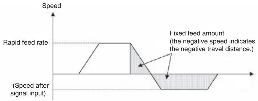
- Only one axis can be specified in one block.
- MOVEI command execution will be completed when positioning for all the specified axes is completed (in-position).
- During the command execution, the command code "0005h" is output to the system variable "Command execution status" (SW0228 for Axis 1). (For details of command codes, see 4-5 System Variables Command Code in Command Execution Status on page 158.)
Time-Specified Positioning (MOVET)
Positioning is executed to the specified position within the specified time period.
Command type
Single execution command
Format
MOVET_[
Operand
Axis name: J01 to J32
| Operand | Setting range | Decimal | Variable specification | INC/ABL influ- ence | ||||
| Bit | Word | Long word | Real number | Indirect specifi- cation | ||||
| Position command value | -2147483648 to 2147483647 | Yes | No | Yes (See note 1.) | Yes | Yes (See note 2.) | Yes | Yes |
| Positioning time | 0 to 3600000 ms | No | No | Yes (See note 1.) | Yes | No | Yes | No |
Note
(1) Word data is extended to long word data with a sign in the MC Unit.
(2) The actual value is determined by the setting value of the parameter [P5AA02: Position command decimal point position].
Description
- Positioning is performed to the position specified with the position command value within the time period specified with the positioning time.
- Speed of each axis is determined by the following expression: [Speed of each axis] = Travel distance of each axis/positioning time
-
When the speed determined by the expression above exceeds the speed specified in the parameter [P2AA01: Maximum rapid feed rate], the alarm [200B: Time specification error] will occur before the operation. The speed after override during an operation is limited by the speed specified in the parameter as well.
-
The actual positioning time can be found using the following expression: [Actual positioning time] = Positioning time + [P2AA05: Rapid feed acceleration time] × [Speed of each axis]/[P2AA03: Rapid feed rate]
- In specifying deceleration, the parameter [P2AA06: Rapid feed deceleration time] is ignored. Instead, the parameter [P2AA05: Rapid feed acceleration time] is used. (Symmetric linear acceleration/deceleration is always performed.)
- The parameter [P2AA03: Rapid feed rate] is ignored.
- If the override is not 100.00% , the positioning time specified cannot be kept.
- Positioning time does not include the time required for completing in-position check.
- MOVET command execution will be completed when positioning for all the specified axes is completed (in-position).
- During the command execution, the command code "0006h" is output to the system variable "Command execution status" (SW0228 for axis 1). (For details of command codes, see 4-5 System Variables Command Code in Command Execution Status on page 158.)
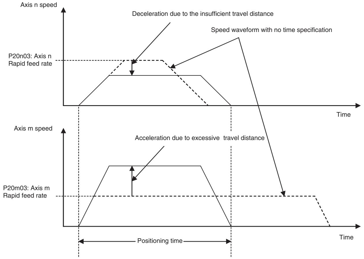
Traverse
(MOVETRAV)
This command is provided for traverse, winding machine operations.
Command type
Single execution command
Format
MOVETRAV_Q
[
{I
Ex: MOVETRV_Q1 [J01]36000.00 [J02]40.00 L10 F2000.00;
Operand
Axis name: J01 to J32
| Operand | Setting range | Decimal | Variable specification | INC/ABL influence | ||||
| Bit | Word | Long word | Real number | Indirect specifi-cation | ||||
| Operating mode | 1,2,3, or 4 | No | No | Yes (See note 1.) | Yes | Yes (See note 2.) | Yes | No |
| Winding axis rota-tions | -2147483648 to 2147483647 | Yes | No | Yes (See note 1.) | Yes | Yes (See note 3.) | Yes | No (see note 4.) |
| Traverse axis wind-ing width | -2147483648 to 2147483647 | Yes | No | Yes (See note 1.) | Yes | Yes (See note 2.) | Yes | No (see note 4.) |
| Number of layers | 2147483647/360 × 10\(^{P5AA02}\) (See note 7.)Figures below decimal point to be omitted (Seeneote 3.) | No | No | Yes (See note 1.) | Yes | Yes (See note 2.) | Yes | No |
| Rotations at starting edge | 0 to 2147483647 | Yes | No | Yes (See note 1.) | Yes | Yes (See note 3.) | Yes | No (see note 4.) |
| Rotations at ending edge | 0 to 2147483647 | Yes | No | Yes (See note 1.) | Yes | Yes (See note 3.) | Yes | No (see note 4.) |
| Winding axis speed | 1 to 2147483647(See note 5.) | Yes | No | Yes (See note 1.) | Yes (see note 6.) | Yes (See note 3.) | Yes | No |
Note
(1) Word data is extended to long word data with a sign in the MC Unit.
(2) Figures below the decimal point are to be omitted.
(3) The actual value is determined by the setting value of the parameter [P5AA02: Position command decimal point position.
(4) There is no influence. INC specification is always used.
(5) The maximum speed in actual operations is limited by the maximum feed rate of the interpolation or axis.
(6) The actual value is determined by the setting value of the parameter [P00M10: Interpolation feed decimal point position].
(7) Position command decimal point position
Description
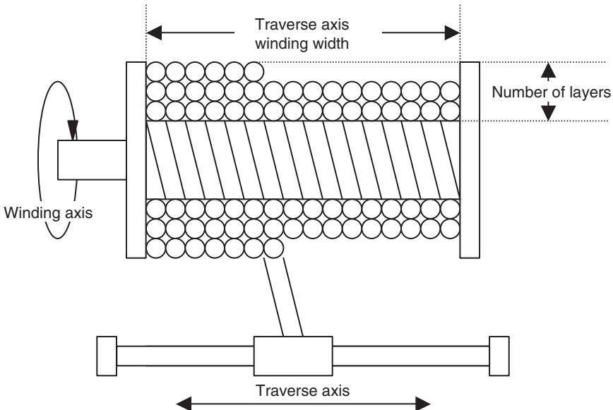
- Description of Operating mode is shown below. It cannot be specified with variables. When linked traverse is specified, only the blocks in the same operating mode can be linked.
1: (Normal traverse, winding axis rotations = Rotations specification)
2: (Normal traverse, winding axis rotations = Pitch specification)
3: (Linked traverse, winding axis rotations = Rotations specification)
4: (Linked traverse, winding axis rotations = Pitch specification) -
Winding axis rotations vary depending on operation mode.
-
Rotations specification: Winding axis rotations per layer. Unit is [deg].
- Pitch specification: Traverse axis travel distance per winding axis rotation
Unit is [command unit/rev].
- When winding axis rotations = 0, the alarm [2009h: Position specification error] will occur.
- A positive or negative value specified in Winding axis rotations corresponds to the rotation direction CCW or CW respectively.
Note The winding axis should be operated in the unlimited feed mode. (If it is operated in the limited feed mode, the alarm [3015h: Axis classification error] will occur.)
- Traverse axis winding width specifies the traverse width ([No. of winds per layer] × [No. of pitches]). Unit is [command unit].
- When Traverse axis winding width = 0, the alarm [2009h: Position specification error] will occur.
- Rotations at starting edge and Rotations at ending edge specify the amount of winding at starting and ending edges. Unit is [deg].
- Without specifying Rotations at starting edge and Rotations at ending edge, there will be no winding at the edges.
- The linked traverse allows up to 100 linked blocks, and the operation as a whole is executed in Stop Mode.
-
The blocks, which were linked using the linked traverse function, are treated as one block.
-
In the linked traverse, up to 5 blocks are interpreted per unit scan. If more than 5 blocks are linked, the time [(No. of linked blocks/5) × Unit scan] will be required for the interpretation (i.e. from completion of executing the previous block to start of the linked traverse operation. (It will take longer to start execution. The operation does not stop during the linked traverse.)
- Linked traverse always operates at the speed specified for the 1st traverse.
- MOVETRAV command execution will be completed when travel distance command output for all the specified axes is completed.
- During the command execution, the command code "0007h" is output to the system variable "Command execution status" (SW0228 for Axis 1). (For details of command codes, see 4-5 System Variables Command Code in Command Execution Status on page 158.)
Electronic Cam, Single Axis (CAM)
Positioning is performed within a specified execution time according to the specified CAM data.
Command type
Single execution command
Format
CAM_[
Axis name: J01 to J32
Operand
| Operand | Setting range | Decimal | Variable specification | INC/ABL influence | ||||
| Bit | Word | Long word | Real number | Indirect specification | ||||
| CAM table number | ±(1 to 32,100,200) | No | No | Yes (See note 1.) | Yes | Yes (See note 2.) | Yes | No |
| Displacement data multiplier | -20000 to 20000 | Yes | No | Yes (See note 1.) | Yes | Yes (See note 3.) | Yes | No |
| Execution time | 0 to 3600000ms | No | No | Yes (See note 1.) | Yes | No | Yes | No |
| Starting data number | 0 to note 4 | No | No | Yes (See note 1.) | Yes | Yes (See note 2.) | Yes | No |
| Ending data number | 0 to note 4 | No | No | Yes (See note 1.) | Yes | Yes (See note 2.) | Yes | No |
Note
(1) Word data is extended to long word data with a sign in the MC Unit.
(2) Figures below the decimal point are to be omitted.
(3) The minimum command unit is 0.01% .
(4) When CAM table is specified: The greatest CAM data number in CAM table
When specifying with global variable: 8188 (1FFC Hex)
When specifying with position data: 10238 (27FE Hex)
Description
- Timed CAM operation is performed according to the CAM table specified with CAM table number.
-
Select CAM table to be used in CAM table number.
-
1-32: Selects the CAM table of the specified number from CAM data.
- 100: Selects the global general variable as CAM table.
-
200: Selects the position data as CAM table.
-
If either the global variable or position data is used for CAM table, phase and displacement are to be specified as double-length integer type data.
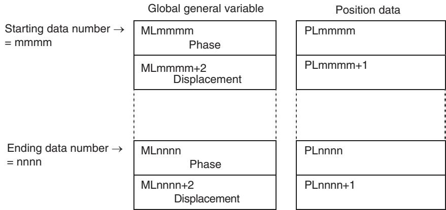
- If a minus sign is added to the CAM table number, the CAM data is read tracing the data numbers in the reverse order.
- The range of Displacement data multiplier is from -200.00 to 200.0% (0.01% unit, limited to the values that can be obtained from the internal processing).
- When "0" is specified in Displacement data multiplier, the operation proceeds to the next block without any axis movement after Execution time specified in T elapses.
- If Starting data number specification is omitted, the starting data number will be 0.
- If Ending data number specification is omitted, the ending data number is the greatest data number in that table.
- If the specifications of [Starting data number] = [Ending data number] are made, the alarm [200Ch: Number specification error] will occur.
- The CAM operation from the starting position to the ending position is executed within the execution time specified in T (Execution time).
- When either of the following conditions is met, the phase will return to 0 (i.e. to the beginning or end of the table) and data is read.
| Data reading direction | Data number |
| Forward | (Starting data number) > (Ending data number) |
| Reverse | (Starting data number) < (Ending data number) |
Note that this operation is executed only when the CAM data is used as the CAM table. If the specifications described above are made when the global general variable or position data is used as the CAM table, the alarm [200Ch: Number specification error] will occur.
- The data reading period is to be one cycle or less.
- The word "Displacement" means the increased value from the CAM command start point.
| Data No. | Phase | Displacement |
| 1 | 0 | 0 |
| 2 | 500 | 400 |
| 3 | 1000 | 1600 |
| 4 | 1500 | 3600 |
| 5 | 2000 | 6400 |
| 6 | 2500 | 10000 |
| 7 | 3000 | 13600 |
| 8 | 3500 | 16400 |
| 9 | 4000 | 18400 |
| 10 | 4500 | 19600 |
| 11 | 5000 | 20000 |
| 12 | 5500 | 19600 |
| 13 | 6000 | 18400 |
| 14 | 6500 | 16400 |
| 15 | 7000 | 13600 |
| 16 | 7500 | 10000 |
| 17 | 8000 | 6400 |
| 18 | 8500 | 3600 |
| 19 | 9000 | 1600 |
| 20 | 9500 | 400 |
| 21 | 10000 | 0 |
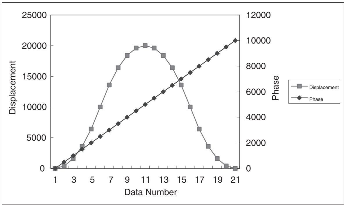
- CAM command execution will be completed when the command output for all the specified CAM data is completed.
- During the command execution, the command code "0008h" is output to the system variable "Command execution status" (SW0228 for Axis 1). (For details of command codes, see 4-5 System Variables Command Code in Command Execution Status on page 158.)
Phase and Displacement of CAM Data
Restriction on phase:
-
To use the CAM data for "CAM (Electronic cam, single axis)" and "CAMBOX (Electronic cam, synchronous)" commands, the phase data should be arranged in an ascending order (i.e. the greater the data number is, the larger the phase will be).
-
When specifying the starting and ending points, the restriction varies depending on the used data as shown below:
| Data | Restriction |
| CAM data | Even with the starting and ending points specified, the other data will not be ignored. Therefore, the conditions mentioned above have to be met even for the unused area. |
| Position data/global general variable | The data other than the starting and ending points specified will be ignored. Therefore, the conditions mentioned above do not have to be met for the unused area. |
- When these conditions are not met, "CAM (Electronic cam, single axis)" and "CAMBOX (Electronic cam, synchronous)" commands may cause the axis to stop operating, or to operate in an unexpected way. To avoid accidents, make sure that the conditions are met.
Note
The position data and global general variable can be used while being overwritten real-time. Therefore, the MC unit does not internally check the conditions for the restrictions mentioned above. (This also applies to the cam data.)
Restriction on the displacement: Set it so that the value is within the setting range.
6-3-3 Command for Axis Operations/Operation Cancel
Link Operation (MOVELINK)
Positioning is performed synchronizing the slave axis to the specified master axis.
Command type
Single execution command
Format
MOVELINK_[
{B
Ex: MOVELINK_[J02]2000.00 [J01]100000.00 A2000.00 D2000.00;
Operand
Axis name: J01 to J32
| Operand | Setting range | Decimal | Variable specification | INC/ABL influence | ||||
| Bit | Word | Long word | Real number | Indirect specification | ||||
| Slave axis travel distance | -2147483648 to 2147483647 | Yes | No | Yes (See note 1.) | Yes | Yes (See note 2.) | Yes | No (See note 4.) |
| Master axis travel distance | 0 to 2147483647 | Yes | No | Yes (See note 1.) | Yes | Yes (See note 2.) | Yes | No (See note 4.) |
| Master axis travel distance in acceleration | 0 to 2147483647 | Yes | No | Yes (See note 1.) | Yes | Yes (See note 2.) | Yes | No (See note 4.) |
| Master axis travel distance in deceleration | 0 to 2147483647 | Yes | No | Yes (See note 1.) | Yes | Yes (See note 2.) | Yes | No (See note 4.) |
| Link option | 0 to 5 | No | No | Yes (See note 1.) | Yes | Yes (See note 3.) | Yes | No |
| Operand | Setting range | Decimal | Variable specification | INC/ABL influ- ence | ||||
| Bit | Word | Long word | Real number | Indirect specifi- cation | ||||
| Link start position | -2147483648 to 2147483647 | Yes | No | Yes (See note 1.) | Yes | Yes (See note 2.) | Yes | No (See note 5.) |
| Master axis classifi- cation | 0 or 1 | No | No | Yes (See note 1.) | Yes | Yes (See note 3.) | Yes | No |
Note
(1) Word data is extended to long word data with a sign in the MC Unit.
(2) The actual value is determined by the setting value of the parameter [P5AA02: Position command decimal point position].
(3) Figures below the decimal point are to be omitted.
(4) There is no influence. INC specification is always used.
(5) There is no influence. ABL specification is always used.
Description
- Synchronous operation is performed with the specifications of acceleration at the beginning of synchronization, ratio in synchronization, and deceleration at synchronization completion.
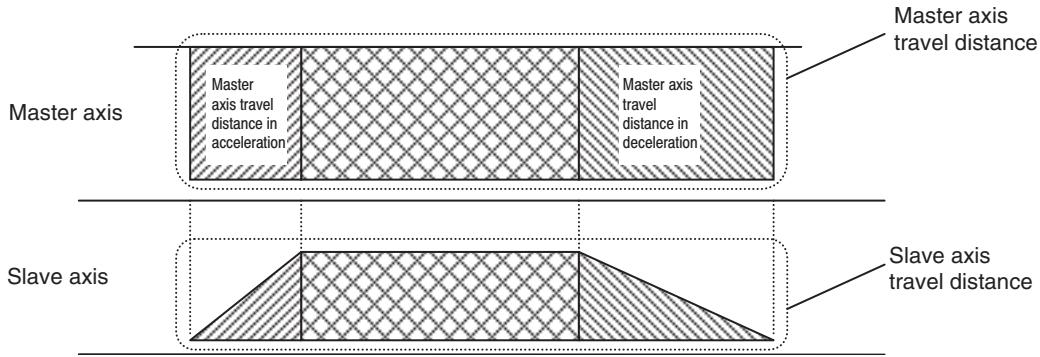
- The travel distances of the master and slave axes for each interval is determined according to the Slave axis travel distance, Master axis travel distance, Master axis travel distance in acceleration, and Master axis travel distance in deceleration as shown in the table below:
| Interval | Master axis | Slave axis | ||
| Acceleration | Master axis travel distance in acceleration | [Slave axis travel distance] × [Master axis travel distance] × [Slave axis travel distance] × [Master axis travel distance] × [Slave axis travel distance] × [Master axis travel distance] × [Slave axis travel distance] × [Master axis travel distance] × [Slave axis travel distance] × [Master axis travel distance] × [Slave axis travel distance] × [Master axis travel distance] × [Slave axis travel distance] × [Master axis travel distance] × [Slave axis travel distance] × [Master axis travel distance] × [Slaveaxis travel distance] × [Master axis travel distance] × [Slaveaxis travel distance] × [Master axis travel distance] × [Slaveaxis travel distance] × [Master axis travel distance] × [Slaveaxis travel distance] × [Master axis travel distance] × [Slaveaxis travel distance] × [Master axis travel distance] × [Slaveaxis travel distance] × [Master axis travel distance] × [Slaveaxis travel distance] × [Master axis travel distance] × [Slaveaxis traveldistance] × [Master axis travel distance] × [Slaveaxis traveldistance] × [Master axis travel distance] × [Slaveaxis traveldistance] × [Master axis travel distance] × [Slaveaxis traveldistance] × [Master axis travel distance] × [Slaveaxis traveldistance] × [Master axis travel distance] × [Slaveaxis traveldistance] × [Master axis travel distance] × [Slaveaxis traveldistance] × [Master axis travel distance] × [Slaveaxis traveldistance]× [Master axis travel distance] × [Slaveaxis traveldistance] × [Master axis travel distance] × [Slaveaxis traveldistance] × [Master axis travel distance] × [Slaveaxis traveldistance] × [Master axis travel distance] × [Slaveaxis traveldistance] × [Master axis travel distance] × [Slaveaxis traveldistance] × [Master axis travel distance] × [Slaveaxis traveldistance] × [Master axis travel distance] × [Slaveaxis traveldistance] × [ Master axis travel distance] × [Slaveaxis traveldistance] × [Master axis travel distance] × [Slaveaxis traveldistance] × [Master axis travel distance] × [Slaveaxis traveldistance] × [Master axis travel distance] × [Slaveaxis traveldistance] × [Master axis travel distance] × [Slaveaxis traveldistance] × [Master axis travel distance] × [Slaveaxis traveldistance] × [Master axis travel distance] × [Slaveaxis traveldistance] × [Master axistraveldistance] × [Slaveaxis traveldistance] × [Master axis traveldistance] × [Slaveaxis traveldistance] × [Master axis traveldistance] × [Slaveaxis traveldistance] × [Master axis traveldistance] × [Slaveaxis traveldistance] × [Master axis traveldistance] × [Slaveaxis traveldistance] × [Master axis traveldistance] × [Slaveaxis traveldistance] × [Master axis traveldistance] × [Slaveaxis traveldistance] × [Master axis traveldistance] × [Slaveaxis traveldistance] × [Master axis traveldistance]\n\n | ||
| Constant speed | Master axis travel distance- Master axis travel distance in acceleration- Master axis travel distance in deceleration | [Slave axis travel distance]- Slave axis travel distance in acceleration - Slave axis travel distance in deceleration | ||
| Deceleration | Master axis travel distance in deceleration | [Slave axis travel distance] × [Master axis travel distance] | ||
| [Master axis travel distance in acceleration] | + Master axis travel distance at constant speed + | [Master axis travel distance in deceleration] | ||
| 2 | 2 | |||
When [Master axis travel distance] < [Master axis travel distance in acceleration] + [Master axis travel distance in acceleration], the actual master axis travel distance in acceleration + the actual master axis travel distance in deceleration = [Master axis travel distance] while maintaining the ratio between the acceleration and deceleration intervals. In this case, the master axis travel distance at constant speed is 0.
- Master axis input ignores signs, and it is treated as the absolute travel distance. Therefore, only the signs of [Slave axis travel distance] determine the direction of the slave axis operation. For example, if the master axis travel direction is reversed during synchronization, the slave axis travel direction will not change.
- The link option influences the following operations depending on the setting value.
| Link option | Command execution completion | Link operation start |
| 0 or omitted | When slave axis travel distance output is completed | When command execution is started |
| 1 | When command execution is started | When command execution is started |
| 2 | When slave axis travel distance output is completed | When latch for master axis is detected |
| 3 | When command execution is started | When latch for master axis is detected |
| 4 | When slave axis travel distance output is completed | When master axis reaches Link start position |
| 5 | When command execution is started | When master axis reaches Link start position |
Note The bit image shown below:
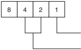
0/1= Slave axis travel distance output completed/With command execution is started
0/1/2 = When command execution is started/ When latch for master axis is detected/ When master axis reaches Link start position
- [Master axis classification] determines whether to synchronize the slave axis with the master axis command value or feedback value.
| Master axis classification | Master axis value to synchronize with |
| 0 or omitted | Command value |
| 1 | Feedback value |
- Completion of command execution varies depending on the link option.
- During the command execution, the command code "0015h" is output to the system variable "Command execution status" (SW0228 for Axis 1). (For details of command codes, see 4-5 System Variables Command Code in Command Execution Status on page 158.)
Precautions When Using MOVELINK Continuously
The timing may need to be adjusted using the NOPS command when the axis is continuously moved using the MOVELINK command. The following example is given as explanation.
As the following program shows, J05 and J04 are joined to the main axis J02 using the MOVELINK command.
If the slave axis J05 is moved immediately after positioning J02 (completion of line 2), the movement of J05 in line 1 is cancelled and J05 will be short one unit cycle of reaching the target position.
This happens because when the MOVELINK command in line 3 is executed, the MOVELINK command in line 1 has not yet completed processing one unit cycle, thereby cancelling this portion of the unit cycle upon the execution of line 3.
MOVELINK [J05]36400 [J02]#ML0002 A0 D0 Q1; (1)
MOVELINK [J04]36400 [J02]#ML0002 A0 D0 Q1;
INC MOVE [J02]#ML0002 (2)
MOVELINK [J05]16000 [J02]#ML0004 A0 D0 Q1; (3)
MOVELINK [J04]16000 [J02]#ML0004 A0 D0 Q1;
INC MOVE [J02]#ML0002
To deal with this problem, insert a NOPS command after the MOVE command as shown below. By inserting the NOPS command, the MOVELINK command will be executed after line 1 is completed.
MOVELINK [J05]36400 [J02]#ML0002 A0 D0 Q1;
MOVELINK [J04]36400 [J02]#ML0002 A0 D0 Q1;
INC MOVE [J02]#ML0002;
NOPS;
MOVELINK [J05]16000 [J02]#ML0004 A0 D0 Q1;
MOVELINK [J04]16000 [J02]#ML0004 A0 D0 Q1;
INC MOVE [J02]#ML0002;
NOPS;
Unit Versions Before Unit Ver. 3.0
If the next operation is executed while the Master axis is continuing to travel, some of the Slave axis travel distance (up to one Unit cycle of travel) will be eliminated.
| Case | First command | Next command | Remarks |
| 1 | CAMBOX | CAMBOX | Part of the travel distance specified in the first CAM table will be eliminated when switching from the first CAM table to the next CAM table. |
| 2 | CAMBOX | MOVELINK | As above. |
| 3 | MOVELINK | CAMBOX | If there is a deceleration area in the first MOVELINK command, part of the deceleration area will be eliminated when switching to the next command. If there is no deceleration area in the first MOVELINK command, the axis will travel the expected travel distance. |
| 4 | MOVELINK | MOVELINK | As above. |
Example: Case 1
:
MOVELINK [J01]30000 [J02]30000 A5000 D5000 Q0;MOVELINK (1)
MOVELINK [J01]30000 [J02]30000 A5000 D5000 Q0;MOVELINK (2)
MOVELINK [J01]30000 [J02]30000 A5000 D5000 Q0;MOVELINK (3)
:
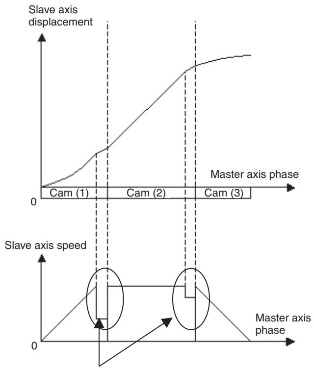
This travel distance will be eliminated.
Unit Ver. 3.0 or Later
The Slave axis will travel the expected distance even if the following operations are performed while the Master axis continues to travel.
| Case | First command | Next command | Remarks |
| 1 | CAMBOX | CAMBOX | Moves the expected travel distance. |
| 2 | CAMBOX | MOVELINK | Moves the expected travel distance. |
| 3 | MOVELINK | CAMBOX | Moves the expected travel distance. |
| 4 | MOVELINK | MOVELINK | Moves the expected travel distance. |
Set the link option (Q) using the following combinations to enable the axes to travel the expected travel distance.
| First command | Next command | ||
| Command | Link option (conditions for command completion) | Command | Link option (conditions for command completion) |
| CAMBOX | 8 (Slave axis travel distance output completed.)10 (Slave axis travel distance output completed.)12 (Slave axis travel distance output completed.) | CAMBOX | 0 or omitted (Slave axis travel distance output completed.)1 (Command execution started.)8 (Slave axis travel distance output completed.)9 (Command execution started.) |
| MOVELINK | 0 or omitted (Slave axis travel distance output completed.)1 (Command execution started.) | ||
| MOVELINK | 0 or omitted (Slave axis travel distance output completed.)2 (Slave axis travel distance output completed.)4 (Slave axis travel distance output completed.) | CAMBOX | 0 or omitted (Slave axis travel distance output completed.)1 (Command execution started.)8 (Slave axis travel distance output completed.)9 (Command execution started.) |
| MOVELINK | 0 or omitted (Slave axis travel distance output completed.)1 (Command execution started.) | ||
Example: Case 1
:
CAMBOX [J01]1 [J02]10000 K10000 Q8 B0; Cam (1)
CAMBOX [J01]2 [J02]10000 K10000 Q8 B0; Cam (2)
CAMBOX [J01]3 [J02]10000 K10000 Q8 B0; Cam (3)
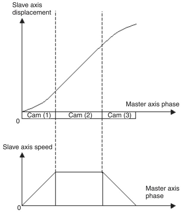
Electronic Cam, Synchronous (CAMBOX)
The operation is executed based on the CAM table synchronizing the slave axis to the specified master axis.
Command type
Single execution command
Format
CAMBOX_[
{S
{I} {B
Ex: CAMBOX[J02]1 [J01]100.00 K100.00;
Axis name: J01 to J32
Operand
| Operand | Setting range | Decimal | Variable specification | INC/ABL influence | ||||
| Bit | Word | Long word | Real number | Indirect specifi-cation | ||||
| CAM table number | ±(1 to 32, 100, 200) | No | No | Yes (See note 1.) | Yes | Yes (See note 2.) | Yes | No |
| Link distance | 0 to 2147483647 | Yes | No | Yes (See note 1.) | Yes | Yes (See note 3.) | Yes | No (See note 4.) |
| Displacement data multiplier | -20000 to 20000 | Yes | No | Yes (See note 1.) | Yes | Yes (See note 5.) | Yes | No |
| Starting data number | 0 to note 6 | No | No | Yes (See note 1.) | Yes | Yes (See note 2.) | Yes | No |
| Ending data number | 0 to note 6 | No | No | Yes (See note 1.) | Yes | Yes (See note 2.) | Yes | No |
| Link option | 1 to 5, 8 to 13 | No | No | Yes (See note 1.) | Yes | Yes (See note 2.) | Yes | No |
| Link start position | -2147483648 to 2147483647 | Yes | No | Yes (See note 1.) | Yes | Yes (See note 3.) | Yes | No (See note 7.) |
| Master axis classifi-cation | 0 or 1 | No | No | Yes (See note 1.) | Yes | Yes (See note 2.) | Yes | No |
Note
(1) Word data is extended to long word data with a sign in the MC Unit.
(2) Figures below the decimal point are to be omitted.
(3) The actual value is determined by the setting value of the parameter [P5AA02: Position command decimal point position].
(4) There is no influence. INC specification is always used.
(5) The minimum command unit is 0.01% .
Real value = ((Value with decimal point or Variable of real number type) × 102)
Figures below the decimal point are to be omitted.
(6) When CAM table is specified: The greatest CAM data number in CAM table
When specified with the global variable: 8188 (1FFC Hex)
When specified with the position data: 10238 (27FE Hex)
(7) There is no influence. ABL specification is always used.
Description
- The synchronous operation is executed based on the CAM table specified with CAM table number.
- The operands, CAM table number, Displacement data multiplier, Starting data number, and Ending data number are handled in the same manner as CAM command.
- Link distance specifies the master axis travel distance per phase cycle.
- Link option influences the following operations depending on the setting value:
| Link option | Command execution completion | Link operation start | Repeat |
| 0 or omitted | When slave axis travel distance output is completed | When command execution is started | Repeat |
| 1 | When command execution is started | When command execution is started | Repeat |
| 2 | When slave axis travel distance output is completed | When latch for master axis is detected | Repeat |
| 3 | When command execution is started | When latch for master axis is detected | Repeat |
| 4 | When slave axis travel distance output is completed | When master axis reaches Link start position | Repeat |
| 5 | When command execution is started | When master axis reaches Link start position | Repeat |
| 8 | When slave axis travel distance output is completed | When command execution is started | Only for one cycle from the starting to ending data number |
| 9 | When command execution is started | When command execution is started | Only for one cycle from the starting to ending data number |
| 10 | When slave axis travel distance output is completed | When latch for master axis is detected | Only for one cycle from the starting to ending data number |
| 11 | When command execution is started | When latch for master axis is detected | Only for one cycle from the starting to ending data number |
| 12 | When slave axis travel distance output is completed | When master axis reaches Link start position | Only for one cycle from the starting to ending data number |
| 13 | When command execution is started | When master axis reaches Link start position | Only for one cycle from the starting to ending data number |
Note The bit image is shown below:
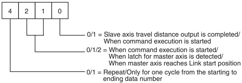
- When the master axis is in reverse rotation, the CAM data is read tracing the data numbers in the reverse order.
- When Link option is one of 8 to 13 (Only for one cycle from the starting to ending data number), the synchronization will be completed once the master axis travels for Link distance in + or - direction from the synchronization start position.
- But if the master axis reciprocates within the ranges of +Link distance] or -{Link distance}, the slave axis continues to move.
- The position of the master axis at link start can be specified with Link start position.
- Master axis classification determines whether to synchronize the slave axis with the master axis command value or feedback value.
| Master axis classification | Master axis value to synchronize with |
| 0 or omitted | Command value |
| 1 | Feedback value |
Command execution completion varies depending on the link option.
- During the command execution, the command code "0016h" is output to the system variable "Command execution status" (SW0228 for Axis 1). (For details of command codes, see 4-5 System Variables Command Code in Command Execution Status on page 158.)
Phase and Displacement of CAM Data
Restriction on phase:
- To use the CAM data for "CAM (Electronic cam, single axis)" and "CAMBOX (Electronic cam, synchronous)" commands, the phase data should be arranged in an ascending order (i.e. the greater the data number is, the larger the phase will be).
- When specifying the starting and ending points, the restriction varies depending on the used data as shown below.
| Data | Restriction |
| CAM data | Even with the starting and ending points specified, the other data will not be ignored. Therefore, the conditions mentioned above have to be met even for the unused area. |
| Position data/Global general variable | The data other than the starting and ending points specified will be ignored. Therefore, the conditions mentioned above do not have to be met for the unused area. |
Note
- When these conditions are not met, "CAM (Electronic cam, single axis)" and "CAMBOX (Electronic cam, synchronous)" commands may cause the axis to stop operating, or to operate in an unexpected way. To avoid accidents, make sure that the conditions are met.
The position data and global general variable can be used while being overwritten real-time. Therefore, the MC unit does not internally check the conditions for the restrictions mentioned above. (This also applies to the cam data.)
Restriction on the displacement:
Set it so that the value is within the setting range.
Precautions When Using Cam Data Continuously
The timing may need to be adjusted using the NOPS command when the axis is continuously moved using the CAMBOX command. The following example is given as explanation.
As the following program shows, J05 and J04 are connected to the main axis J02 using the CAMBOX command. If the slave axis J05 is moved immediately after J02 positioning (completion of line 2), the movement of J05 in line 1 is cancelled and J05 will be short one unit cycle of reaching the target position. This happens because when the CAMBOX command in line 3 is executed, the CAMBOX command in line 1 has not yet completed processing one unit cycle, thereby cancelling this unit cycle upon the execution of line 3.
CAMBOX [J05]1 [J02]1000 K10000 Q9; (1)
CAMBOX [J04]2 [J02]1000 K10000 Q9;
INC MOVE [J02]1000; (2)
CAMBOX [J05]1 [J02]1000 K10000 Q9; (3)
CAMBOX [J04]2 [J02]1000 K10000 Q9;
INC MOVE [J02]1000;
To deal with this problem, insert a NOPS command after the MOVE command as shown below. By inserting the NOPS command, the CAMBOX command will be executed after line 1 is completed.
CAMBOX [J05]1 [J02]1000 K10000 Q9;
CAMBOX [J04]2 [J02]1000 K10000 Q9;
INC MOVE [J02]1000;
NOPS;
CAMBOX [J05]1 [J02]1000 K10000 Q9;
CAMBOX [J04]2 [J02]1000 K10000 Q9;
INC MOVE [J02]1000;
NOPS;
Unit Versions Before Unit Ver. 3.0
If the next operation is executed while the Master axis is continuing to travel, some of the Slave axis travel distance (up to one Unit cycle of travel) will be eliminated.
| Case | First command | Next command | Remarks |
| 1 | CAMBOX | CAMBOX | Part of the travel distance specified in the first CAM table will be eliminated when switching from the first CAM table to the next CAM table. |
| 2 | CAMBOX | MOVELINK | As above. |
| 3 | MOVELINK | CAMBOX | If there is a deceleration area in the first MOVELINK command, part of the deceleration area will be eliminated when switching to the next command. If there is no deceleration area in the first MOVELINK command, the axis will travel the expected travel distance. |
| 4 | MOVELINK | MOVELINK | As above. |
Note The axis will travel the expected distance when operation is repeated using the CAMBOX command (link options 0 to 5).
Example: Case 1
:
CAMBOX [J01]1 [J02]10000 K10000 Q8 B0; Cam (1)
CAMBOX [J01]2 [J02]10000 K10000 Q8 B0; Cam (2)
CAMBOX [J01]3 [J02]10000 K10000 Q8 B0; Cam (3)
:
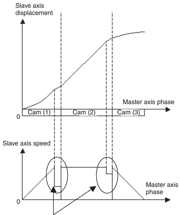
This travel distance will be eliminated.
Unit Ver. 3.0 or Later
The Slave axis will travel the expected distance even if the following operations are performed while the Master axis continues to travel.
| Case | First command | Next command | Remarks |
| 1 | CAMBOX | CAMBOX | Moves the expected travel distance. |
| 2 | CAMBOX | MOVELINK | Moves the expected travel distance. |
| 3 | MOVELINK | CAMBOX | Moves the expected travel distance. |
| 4 | MOVELINK | MOVELINK | Moves the expected travel distance. |
Set the link option (Q) using the following combinations to enable the axes to travel the expected travel distance.
| First command | Next command | ||
| Command | Link option (conditions for command completion) | Command | Link option (conditions for command completion) |
| CAMBOX | 8 (Slave axis travel distance output completed.)10 (Slave axis travel distance output completed.)12 (Slave axis travel distance output completed.) | CAMBOX | 0 or omitted (Slave axis travel distance output completed.)1 (Command execution is started.)8 (Slave axis travel distance output completed.)9 (Command execution started) |
| MOVELINK | 0 or omitted (Slave axis travel distance output is completed.)1 (Command execution started.) | ||
| MOVELINK | 0 or omitted (Slave axis travel distance output completed.)2 (Slave axis travel distance output completed.)4 (Slave axis travel distance output completed.) | CAMBOX | 0 or omitted (Slave axis travel distance output completed.)1 (Command execution started.)8 (Slave axis travel distance output completed.)9 (Command execution started.) |
| MOVELINK | 0 or omitted (Slave axis travel distance output completed.)1 (Command execution started.) | ||
Example: Case 1
:
CAMBOX [J01]1 [J02]10000 K10000 Q8 B0; Cam (1)
CAMBOX [J01]2 [J02]10000 K10000 Q8 B0; Cam (2)
CAMBOX [J01]3 [J02]10000 K10000 Q8 B0; Cam (3)
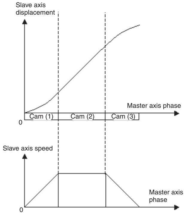
Electronic Shaft (CONNECT)
Command type
Format
Positioning is performed synchronizing the slave axis to the specified master axis based on the specified gear ratio.
Single execution command
CONNECT_[
Ex: CONNECT_[J02]1 [J03]2 [J04]3 [J01]100;
Operand
Axis name: J01 to J32
| Operand | Setting range | Decimal | Variable specification | INC/ABL influence | ||||
| Bit | Word | Long word | Real number | Indirect specification | ||||
| Gear ratio numerator | -10000 to 10000 | No | No | Yes (See note 1.) | Yes | Yes (See note 2.) | Yes | No |
| Gear ratio denominator | 1 to 10000 | No | No | Yes (See note 1.) | Yes | Yes (See note 2.) | Yes | No |
| Master axis classification | 0 or 1 | No | No | Yes (See note 1.) | Yes | Yes (See note 2.) | Yes | No |
Note
(1) Word data is extended to long word data with a sign in the MC Unit.
(2) Figures below the decimal point are to be omitted.
Description
- Synchronous operation is performed in the ratio Gear ratio numerator/Gear ratio denominator.
- The value in Gear ratio denominator is common for all the slave axes. If there are different ratios within one block, they are to be reduced to a common denominator to set the ratios.
-
A negative value can also be set for Gear ratio numerator, which can make the travel directions of the master and slave axes opposite.
-
Master axis classification determines whether to synchronize the slave axis with the master axis command value or feedback value.
| Master axis classification | Master axis value to synchronize with |
| 0 or omitted | Command value |
| 1 | Feedback value |
- If the speed obtained by multiplying the master axis speed and the gear ratio exceeds the speed specified in the parameter [P2AA01: Maximum rapid feed rate], the alarm [3011h: Synchronizing slave axis excessive speed] will occur.
- CONNECT command execution will be completed when the electronic shaft synchronization for all the specified axes are established.
- During the command execution, the command code "0017h" is output to the system variable "Command execution status" (SW0228 for Axis 1). (For details of command codes, see 4-5 System Variables Command Code in Command Execution Status on page 158.)
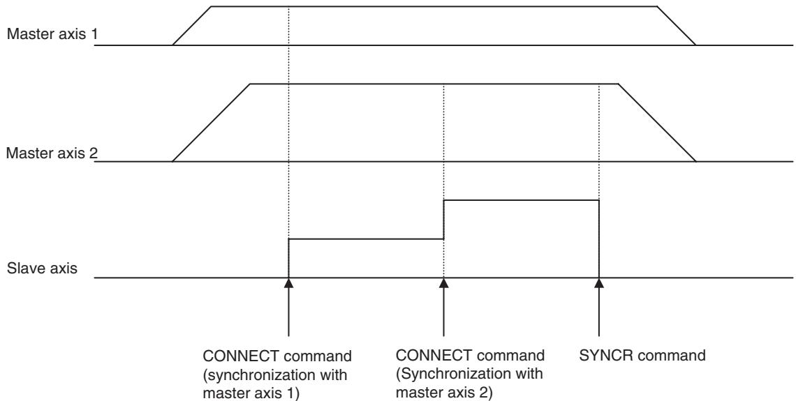
Trailing Synchronization (SYNC)
The Trailing Synchronization (SYNC) command performs trailing synchronization operation with a specified master axis.
Command type
Single execution command
Format
SYNC_[
Ex: SYNC_[J02]100.00 [J01]20.0;
Operand
Axis name: J01 to J32
| Operand | Setting range | Decimal | Variable specification | INC/ABL influence | ||||
| Bit | Word | Long word | Real number | Indirect specification | ||||
| Catch-up position offset | -2147483648 to 2147483647 | Yes | No | Yes (See note 1.) | Yes | Yes (See note 2.) | Yes | No (See note 3.) |
| Marker sensor ON position | -2147483648 to 2147483647 | Yes | No | Yes (See note 1.) | Yes | Yes (See note 2.) | Yes | No (See note 5.) |
| Master axis classification | 0 or 1 | No | No | Yes (See note 1.) | Yes | Yes (See note 4.) | Yes | No |
Note
(1) Word data is extended to long word data with a sign in the MC Unit.
(2) The actual value is determined by the setting value of the parameter [P5AA02: Position command decimal point position].
(3) There is no influence. INC specification is always used.
(4) Figures below the decimal point are to be omitted.
(5) There is no influence. ABL specification is always used.
Description
- Synchronization proceeds in the order described below:
- The slave axis will wait for the marker sensor signal after the execution is started. (It waits for the marker sensor signal input to the master axis.)
- The slave axis will start trailing operation when the marker sensor signal is input. The trailing operation will be completed once the slave axis synchronizes with the position of the master axis (Marker sensor ON position + catch-up position offset).
- The slave axis is operated synchronizing with the master axis in the ratio of 1 to 1.
- Catch-up position offset is specified as the distance from Marker sensor ON position on the coordinate system of the slave axis.
- Marker sensor ON position is specified as the position on the coordinate system of the slave axis.
- If the speed in synchronization exceeds the speed specified in the parameter [P2AA01: Maximum rapid feed rate], the alarm [3011h: Synchronizing slave axis excessive speed] will occur.
- Master axis classification determines whether to synchronize the slave axis with the master axis command value or feedback value.
| Master axis classification | Master axis value to synchronize with |
| 0 or omitted | Command value |
| 1 | Feedback value |
- SYNC command execution will be completed when the trailing operation is completed and the synchronization is established.
- During the command execution, the command code "0018h" is output to the system variable "Command execution status" (SW0228 for Axis 1). (For details of command codes, see 4-5 System Variables Command Code in Command Execution Status on page 158.)
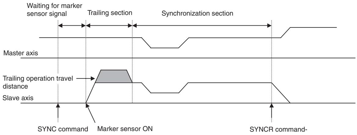
Synchronization Cancel (SYNCR)
Synchronous operation executed with the synchronous command is cancelled.
Command type
Single execution command
Format
SYNCR_[
Ex:SYNCR_[J02];
Operand
Axis name: J01 to J32
| Operand | Setting range | Decimal | Variable specification | INC/ABL influ- ence | ||||
| Bit | Word | Long word | Real number | Indirect specifi- cation | ||||
| Travel distance for deceleration stop | 0 to 2147483647 | Yes | No | Yes (See note 1.) | Yes | Yes (See note 2.) | Yes | No (See note 3.) |
Note
(1) Word data is extended to long word data with a sign in the MC Unit.
(2) The actual value is determined by the setting value of the parameter [P5AA02: Position command decimal point position].
(3) There is no influence. INC specification is always used.
Description
- Synchronization started with MOVELINK, CAMBOX, CONNECT, or SYNC command is canceled with deceleration stop.
- The slave axis not performing synchronous operation is ignored.
- The speed for deceleration stop follows the speed specified in the parameter [P2AA03: Rapid feed rate]. So, acceleration or deceleration may occur depending on the speed at the start of command execution.
- The deceleration for deceleration stop observes the speed determined by the setting values in the parameter [P2AA03: Maximum rapid feed rate] and [P2AA06: Rapid feed deceleration time].
- When Travel distance for deceleration stop is not specified, behavior will vary depending on the command.
| Command | Behavior |
| MOVELINK | Immediate stop |
| CAMBOX | Immediate stop |
| CONNECT | Immediate stop |
| SYNC | Deceleration stop with the specified deceleration |
- If Travel distance for deceleration stop is smaller than the distance required for deceleration stop from the current speed (speed of the previous scan), return operation is performed after the deceleration stop.
- SYNCRC command execution will be completed when positioning (including the return operation) for all the specified axes are completed (in-position).
- During the command execution, the command code "0029h" is output to the system variable "Command execution status" (SW0228 for Axis 1). However, when the travel distance specification is omitted, the command code of the corresponding synchronous command is held. (For details of command codes, see 4-5 System Variables Command Code in Command Execution Status on page 158.)
Travel Distance Superimpose/Travel Distance Superimpose Cancel (ADDAX/ADDAXR)
The travel distance of the specified master axis is superimposed onto the slave axis operation.
Command type
Single execution command
Format
ADDAX_[
ADDAXR_{{[
Ex: ADDAX[J02] [J01];
ADDAXR_[J02];
Operand
Axis name: J01 to J32
| Operand | Setting range | Decimal | Variable specification | INC/ABL influence | ||||
| Bit | Word | Long word | Real number | Indirect specification | ||||
| Master axis classification | 0 or 1 | No | No | Yes (See note 1.) | Yes | Yes (See note 2.) | Yes | No |
Note
(1) Word data is extended to long word data with a sign in the MC Unit.
(2) Figures below the decimal point are to be omitted.
Description
- The travel distance of the specified master axis is superimposed onto the slave axis operation.
- Master axis classification determines whether to synchronize the slave axis with the master axis command value or feedback value.
| Master axis classification | Master axis value to synchronize with |
| 0 or omitted | Command value |
| 1 | Feedback value |
- Executing another ADDAX command on the axis that is already in superimposing operation can establish new superimposing relations (overwritten).
- If the speed in superimposition exceeds the speed specified in the parameter [P2AA01: Maximum rapid feed rate], the alarm [3011h: Synchronizing slave axis excessive speed] will occur.
-
ADDAX command execution will be completed when superimposition is established.
-
If Slave axis name is omitted in ADDAXR command, all the superimposition being executed in the same motion task will be cancelled.
- ADDAXR command execution will be completed when superimposition is cancelled.
- During the command execution, the command code "0019h" is output to the system variable "Command execution status" (SW0228 for Axis 1). (For details of command codes, see 4-5 System Variables Command Code in Command Execution Status on page 158.)
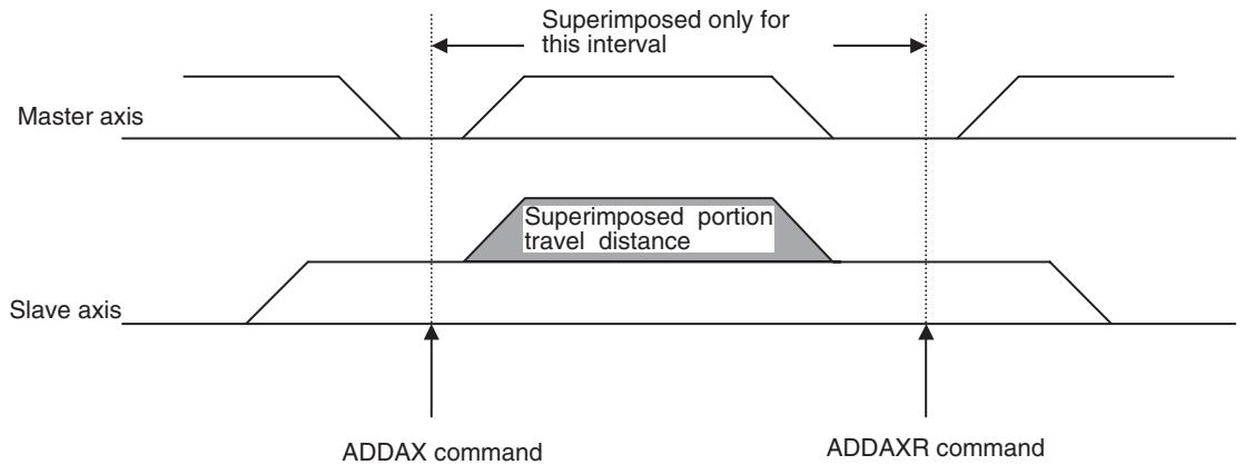
Caution
When a command that has waiting conditions such as Stop Mode is executed on the slave axis, the waiting conditions may not be satisfied in some cases. See the following example:
Ex:
... ADDAX [J02] [J01];
PARALLEL N2;
MOVE [J01]1000.;
JOINT;
MOVE [J02] 500;
J02 is the slave axis in the superimposition. Positioning only up to 500. is not sufficient for in-position, which means that the MOVE command cannot be completed. Practically, it will be completed after the movement of [J01] (2 lines before) is completed. To avoid waiting for completion of [J01], it is necessary to replace use MOVEL in Pass Mode, etc.
Speed Control/Speed Control Cancel (SPEED/SPEEDR)
The speed of the axis is controlled in the speed control mode.
Command type
Single execution command
Format
SPEED_[
SPEEDR_[
Ex: SPEED_[J01]100.00 [J02]100.00 T100;
SPEEDR[J01] [J02] _T100;
Operand
Axis Name: J01 to J32
| Operand | Setting range | Decimal | Variable specification | INC/ABL influ- ence | ||||
| Bit | Word | Long word | Real number | Indirect specifi- cation | ||||
| Speed command value | See note 1. | Yes | No | Yes (See note 2.) | Yes | Yes (See note 3.) | Yes | No (See note 4.) |
| Speed change rate | 0 to 60000ms | No | No | Yes (See note 2.) | Yes | Yes | Yes | No |
Note
(1) With Rated % specification (P00004 bit2 = 0):
This is the % specification for the motor rated rotations in the unit of 0.01% . The setting range is -500000 to 500000.
If the value 10000 is set, it is interpreted as 100% of the rated rotations.
The maximum speed in actual operations is limited by the maximum rotation speed of the motor.
With r/min specification (P00004 bit2 = 1):
This is the specification of rotations (r/min) in the unit of 0.01 r/min. Setting range is -10000000 to 10000000.
If the value 300000 is set, it is interpreted as 3000r / min
The maximum speed in actual operations is limited by the maximum rotation speed of the motor.
(2) Word data is extended to long word data with a sign in the MC Unit.
(3) With Rated % specification (P00004 bit2 = 0)
The minimum command unit is 0.01% .
The actual value = (Decimal immediate value or Variable of real number type) × 10^2
Figures below the decimal point are to be omitted.
In case of r/min specification (P00004 bit2 = 1)
The minimum command unit is 0.01% .
The actual value = ((Decimal immediate value or Variable of real number type) × 10²)
Figures below the decimal point are to be omitted.
(4) There is no influence. ABL specification is always used.
Description
- The speed command is output to the specified axis.
- The speed command unit is specified in the parameter [P00004.bit02: Unit function select, Speed command value]
[P00004.bit02] = 0 [0.01% of the rated speed]
[P00004.bit02] = 1 [0.01r/min]
- If Speed change rate is set to 0, the specified speed is output instantly. (If the mode is switched from other mode to the speed control mode, this value can be used as the output speed default value.)
- The Speed change rate is enabled for all the specified axes.
- SPEED command execution will be completed when the speed command for all the specified axes reaches Speed command value.
- The SPEEDDR command is processed as follows:
(1) The speed command is decelerated for all specified axes according to the speed change rate and the speed command is output as 0.
(2) The system waits until the feedback speed equals the speed in P3AA09 or lower.
(3) The mode is switched to positioning control mode and the system waits for the completion of positioning.
(4) Command execution is completed.
- During the command execution, the command code "001Ah" is output to the system variable "Command execution status" (SW0228 for Axis 1). (For details of command codes, see 4-5 System Variables Command Code in Command Execution Status on page 158.)
Caution
The maximum time required from starting SPEED command to completing the command is 136ms + (Actual acceleration time/unit cycle).
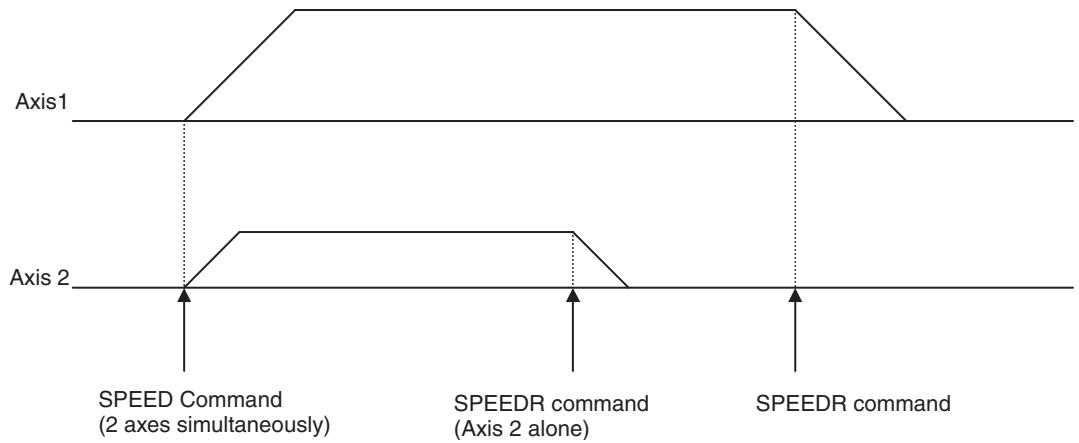
- When executing the SPEED command, the following axis command position values are output to system variables (refer to 4-5 System Variables).
Current coordinate command position: Same value as current coordinate FB position
Machine coordinate current position: Same value as machine coordinate FB position
- If MOVE command is executed without SPEEDR command, the mode can be switched from the speed control mode to the position control mode. To change the speed of SPEED command being executed to the rapid feed rate of MOVE command smoothly, the system automatically reads the position loop gain before starting execution of SPEED command except for the following cases:
1) When the position loop gain before execution of SPEED command is different from the position loop gain right after transition to the MOVE command.
2) When the position loop gain could not be read successfully due to incorrect setting of the servo reading parameter.
In order to prevent shock, follow the instructions below:
- Do not use MOVE command right after acceleration or deceleration.
- Set the unit cycle and communication cycle to be the same.
-
Decrease the speed specified in SPEED command.
-
The Speed change rate of SPEED/SPEEDR specifies the time to reach the motor rated speed from zero.
Program Image
SPEED [J01]
SPEED [J01]
SPEED [J01]
SPEEDR [J01] T
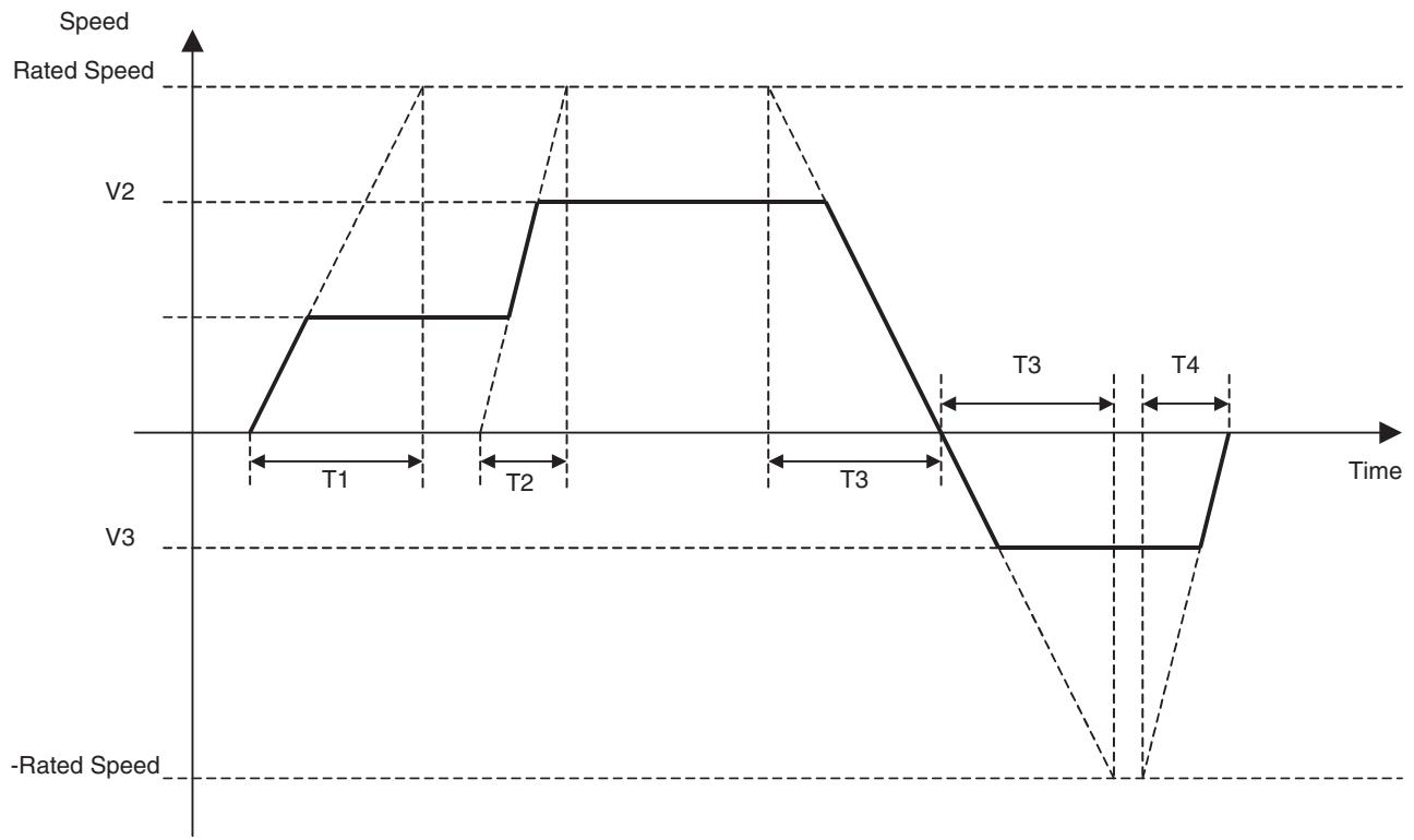
Torque Control/
Torque Control cancel (TORQUE/TORQUER)
The axes Torque can be controlled in Torque Control mode.
Command type
Single execution command
Format
TORQUE_[
TORQUER_[
Ex: TORQUE_[J01]100.00 [J02]100.00 _T100;
TORQUER_[J01][J02]_T100;
Operand
Axis name: J01 to J32
| Operand | Setting range | Decimal | Variable specification | INC/ABL influ- ence | ||||
| Bit | Word | Long word | Real number | Indirect specifi- cation | ||||
| Torque command value | -10000 to 10000 (See note 1.) | No | No | Yes (See note 2.) | Yes | Yes (See note 3.) | Yes | No (See note 4.) |
| Torque change rate | 0 to 60000ms | Yes | No | Yes (See note 2.) | Yes | No | Yes | No |
Note
(1) This is the % specification for the maximum motor torque in the unit of 0.01% . When the value 10000 is set, it is interpreted as 100% of the maximum torque. The maximum motor torque limits the maximum torque in actual operations.
(2) Word data is extended to long word data with a sign in the MC Unit.
(3) The minimum command unit is 0.01% . Real value = (Decimal immediate value or Variable of real number type) × 10^2 Figures below the decimal point are to be omitted.
(4) There is no influence. ABL specification is always used.
Description
- The torque command is output to the specified axis. (Torque value on the motor axis is controlled.)
- The torque command unit is fixed at 0.01% of the maximum torque.
- If Torque change rate is set to 0, the specified torque is output instantly (If the mode is switched from other mode to the torque control mode, this value can be used as the output torque default value.)
- Torque change rate is enabled for all the specified axes.
- TORQUE command execution will be completed when the torque command for all the specified axes reaches Torque command value.
- The TORQUER command is processed as follows:
(1) The torque command is deceleration for all specified axes according to the torque change rate and the torque command is output as 0.
(2) The system waits until the feedback speed equals the speed in P3AA09 or lower.
(3) The mode is switched to positioning control mode and the system waits for the completion of positioning.
(4) Command execution is completed.
- During the command execution, the command code "001Bh" is output to the system variable "Command execution status" (SW0228 for Axis 1). (For details of command codes, see 4-5 System Variables Command Code in Command Execution Status on page 158.)
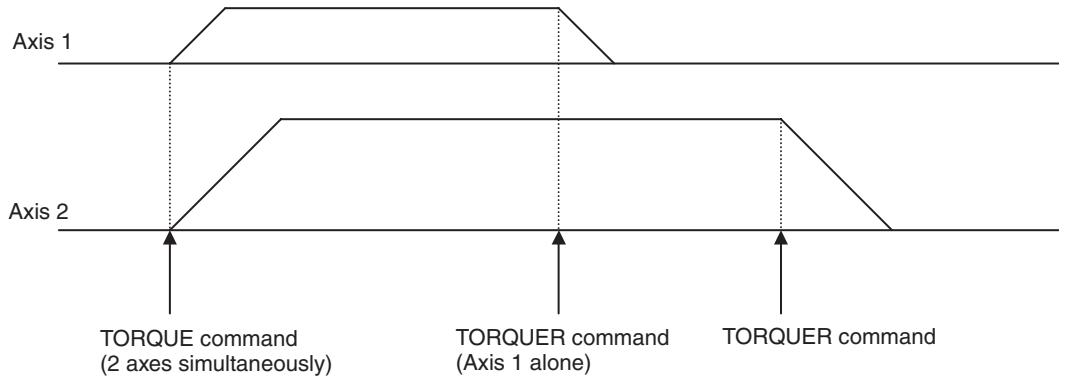
- Torque change rate of TORQUE/TORQUER specifies the time to reach the motor maximum torque from 0.
Program image
TORQUE [J01]<Tq1>T <T1>; Torque control started TORQUE [J01]<Tq2>T <T2>; Torque changed TORQUE [J01]<Tq3>T <T3>; Torque and direction changed TORQUER [J01] T <T4>; Torque control completed
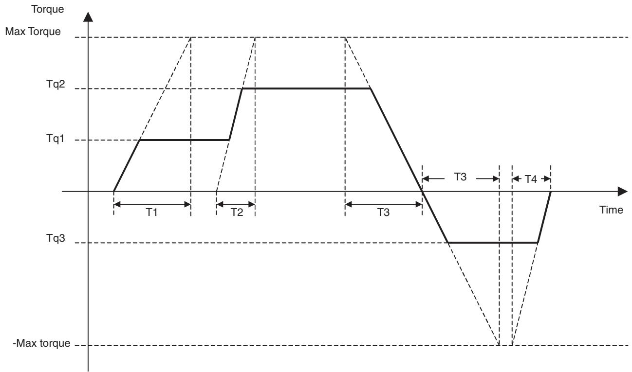
Caution
When executing the TORQUE command, the following axis command position values are output to system variables (refer to 4-5 System Variables).
Command speed 1: Same value as feedback speed 1
Command speed 2: Same value as feedback speed 2
6-3-4 Setting Command
Target Position Change (MOVEMODI)
The target position of the positioning command currently being executed is changed.
Command type
Multiple execution command
Format
MOVEMODI_[
Ex: MOVEMODI_[J01]100.00 [J02]200.00;
Operand
Axis name: J01 to J32
| Operand | Setting range | Decimal | Variable specification | INC/ABL influ- ence | ||||
| Bit | Word | Long word | Real number | Indirect specifi- cation | ||||
| Changed target posi- tion | -2147483648 to 2147483647 | Yes | No | Yes (See note 1.) | Yes | Yes (See note 2.) | Yes | No (See note 3.) |
Note
(1) Word data is extended to long word data with a sign in the MC Unit.
(2) The actual value is determined by the setting value of the parameter [P5AA02: Position command decimal point position].
(3) There is no influence. ABL specification is always used.
Description
- The target position of the axis being operated with MOVE command or MOVEL command of 1 axis specification in Stop Mode is changed to Changed target position.
- MOVEMODI command is ignored during execution of commands other than the above or when it is executed for the axis not operating.
- Changed target position is treated as the absolute position on the coordinate system currently being selected.
- If Changed target position has already been passed, return operation is performed.
- The relations between the remaining travel distance and acceleration/ deceleration on the axis of MOVEMODI object are as shown in the table below:
| Speed status | Remaining travel distance | |
| When remaining travel distance is increased | When remaining travel distance is decreased | |
| In acceleration | Keeps accelerating | If there is still sufficient travel distance left, acceleration is maintained. If there is not sufficient travel distance, deceleration stop is executed and return operation is performed. |
| At constant speed | Stays at constant speed | If there is still sufficient travel distance left, constant speed is maintained. If there is not sufficient travel distance, deceleration stop is executed and return operation is performed. |
| In deceleration (Due to insufficient remaining travel distance) | Stops decelerating and accelerates again | Deceleration stop is executed and return operation is performed. |
- MOVEMODI command execution is completed when the target position is changed internally and completed successfully. There is no influence of the operation status of the axis whose target position has been changed.
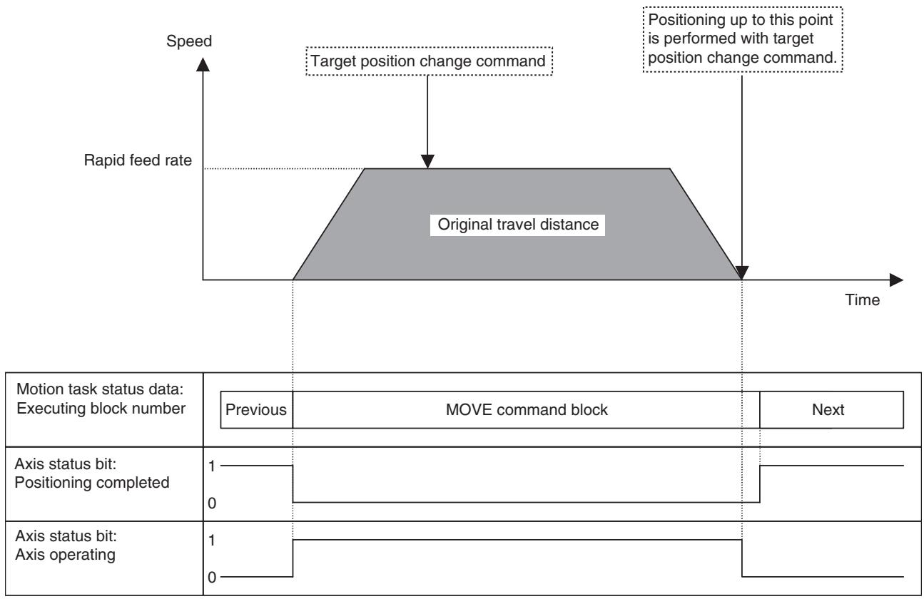
Absolute Specification (ABL)
Command type
Format
Operand
Description
Incremental Specification (INC)
Command type
Format
Operand
Description
In axis operations, positioning is performed with absolute specification on each coordinate system.
Multiple execution command
ABL;
ABL_
Ex: ABL_MOVE [J01]1000.00 [J02]2000.00;
Nil
Command values after ABL command are interpreted as absolute (target value) specification.
In axis operations, positioning is performed with relative specification.
Multiple execution command
INC;
INC_
Ex: INC_MOVE [J01]1000.00 [J02]2000.00;
Nil
Command values after INC command are interpreted as incremental (incremental value) specification.
Change Parameter Value (PARAM)
The setting of the specified parameter is changed.
Command type
Single execution command
Format
PARAM_P
PARAM_[[axis name>]
Ex: PARAM P1 = 2;
Operand
Axis name: J01 to J32
| Operand | Setting range | Decimal | Variable specification | INC/ABL influence | ||||
| Bit | Word | Long word | Real number | Indirect specification | ||||
| Parameter number | 0 to 65535 | No | No | Yes (See note 1.) | Yes | Yes (See note 2.) | Yes | No |
| Parameter setting value | -2147483648 to 2147483647 | No | No | Yes (See note 1.) | Yes | Yes (See note 2.) | Yes | No |
| Servo parameter number | 000 to 8FF [Hex] | No | No | Yes (See note 1.) | Yes | Yes (See note 2.) | Yes | No |
Note
(1) Word data is extended to long word data with a sign in the MC Unit.
(2) The actual value is determined by the setting value of the parameter [P5AA02: Position command decimal point position].
Description
- System parameters or servo parameters are changed.
- Only one parameter can be changed per command.
- From a motion task, only system parameters related to the motion task itself and only system parameters or servo parameters related to the axis reserved by axis declaration can be changed.
- The parameters that can be changed using PARAM command are the ones that can be changed after power is turned ON (i.e. the parameters that can be changed without turning OFF the power once, then ON again). If a parameter that cannot be changed is changed, the alarm [2019h: Parameter setting error] will occur.
-
Parameters changed using PARAM command remains enabled until any one of the following is executed:
-
Power is turned ON or Unit is restarted.
- PARAM command is executed.
- Parameter is changed using IOWR instruction.
-
Parameter is downloaded from a the Support Tool.
-
PARAM command execution will be completed when the parameter is overwritten successfully.
Caution
The following time is required from when the PARAM command execution starts until execution is completed.
| Parameter type | Unit cycle Tm (ms) | Execution time (ms) |
| Servo driver parame-ters | 1 ms, 2 ms | { (20/Tm) × 3 + 2} × Tm to { (20/Tm) × 4 + 2} × Tm |
| 3 ms, 4 ms, 6 ms, or 8 ms | { (20/Tm) × 4 + 2} × Tm to { (20/Tm) × 5 + 2} × Tm | |
| Other parameters | 1 ms, 2 ms, 3 ms, 4 ms, 6 ms, or 8 ms | { (20/Tm) × 1 + 2} × Tm to { (20/Tm) × 2 + 2} × Tm |
For example, when changing the interpolation feed speed for motion task parameters with a unit cycle of 2 ms, the execution time will be 24 to 44 ms.
Pass Mode (PASSMODE)
The operating mode is switched to Pass Mode.
Command type
Multiple execution command
Format
PASSMODE;
Ex:PASSMODE;
Operand
Nil
Description
- Interpolation blocks (MOVEL/MOVEC/MOVETRAV) after PASSMODE command are executed in Pass Mode.
Interpolation 1
Interpolation 2
Interpolation 3
- There are four modes for linking speeds, one of which can be selected in the parameter [P00M06: Pass mode select].
| P00M06 | Name | Operation |
| 0 | Interpolation acceleration time + Acceleration disabled | Operation proceeds to the next using interpolation acceleration time of the previous block. |
| 1 | Interpolation deceleration time+ Acceleration disabled | Operation proceeds to the next using interpolation deceleration time of the previous block. |
| 2 | Interpolation acceleration time+ Acceleration enabled | Operation proceeds to the next using interpolation acceleration time of the previous block. For 1-axis linear interpolation, speeds are changed with fixed acceleration/deceleration. |
| 3 | Interpolation deceleration time+ Acceleration enabled | Operation proceeds to the next using interpolation deceleration time of the previous block. For 1-axis linear interpolation, speeds are changed with fixed acceleration/deceleration. |
Stop Mode (STOPMODE)
The operating mode is switched to Stop Mode.
Command type
Multiple execution command
Format
STOPMODE;
Ex: STOPMODE;
Operand
Nil
Description
Interpolation blocks (MOVEL/MOVEC/MOVETRAV) following STOPMODE command proceeds to the next block after entering No. 2 in-position range specified in the parameter [P3AA07: No.2 in-position range]. (Interpolation for the next block will start after speed decreases to 0 and positioning enters No.2 in-position range.)
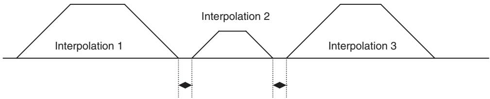
Interpolation for the next block will be executed after the previous block enters No.2 in-position range.
| Machine Coordinate System Select (ORIGIN) | Coordinate system is switched to the machine coordinate system. |
| Command type | Single execution command |
| Format | ORIGIN; Ex: ORIGIN; |
| Operand | Nil |
| Description | • Coordinate values after ORIGIN command are treated as values on the machine coordinate system. Note Defining an origin using origin search, etc. sets the machine coordinate system. • All the axes that are declared with the previous PROG command (main PROG for main programs, sub PROG for subprograms) are the objects of ORIGIN command. • The selected coordinate system will stay enabled until ORIGIN/WORK commands are executed, or until a new program execution is started. |
| Workpiece Coordinate System Select (WORK) | Coordinate system is switched to the workpiece coordinate system. |
| Command type | Single execution command |
| Format | WORK_C<workpiece coordinate system number>; Ex: WORK_C1; |
Operand
| Operand | Setting range | Decimal | Variable specification | INC/ABL influ- ence | ||||
| Bit | Word | Long word | Real number | Indirect specifi- cation | ||||
| Workpiece coordi- nate system number | 1, 2, or 3 (See note 3.) | No | No | Yes (See note 1.) | Yes | Yes (See note 2.) | Yes | No |
Note
(1) Word data is extended to long word data with a sign in the MC Unit.
(2) Figures below the decimal point are to be omitted.
(3) There are three workpiece coordinate systems for each axis.
Description
- Coordinate values after WORK command are treated as values on the workpiece coordinate system.
- There are three workpiece coordinate systems for each axis, and they are specified using coordinate system numbers.
- All the axes that are declared with the previous PROG command (main PROG for main programs, sub PROG for subprograms) are the objects of WORK command.
- Workpiece coordinate system will stay enabled until ORIGIN/WORK is executed, or until a new program execution is started.
- Offsets for the workpiece coordinate systems against the machine coordinate system are set with OFFPOS command.
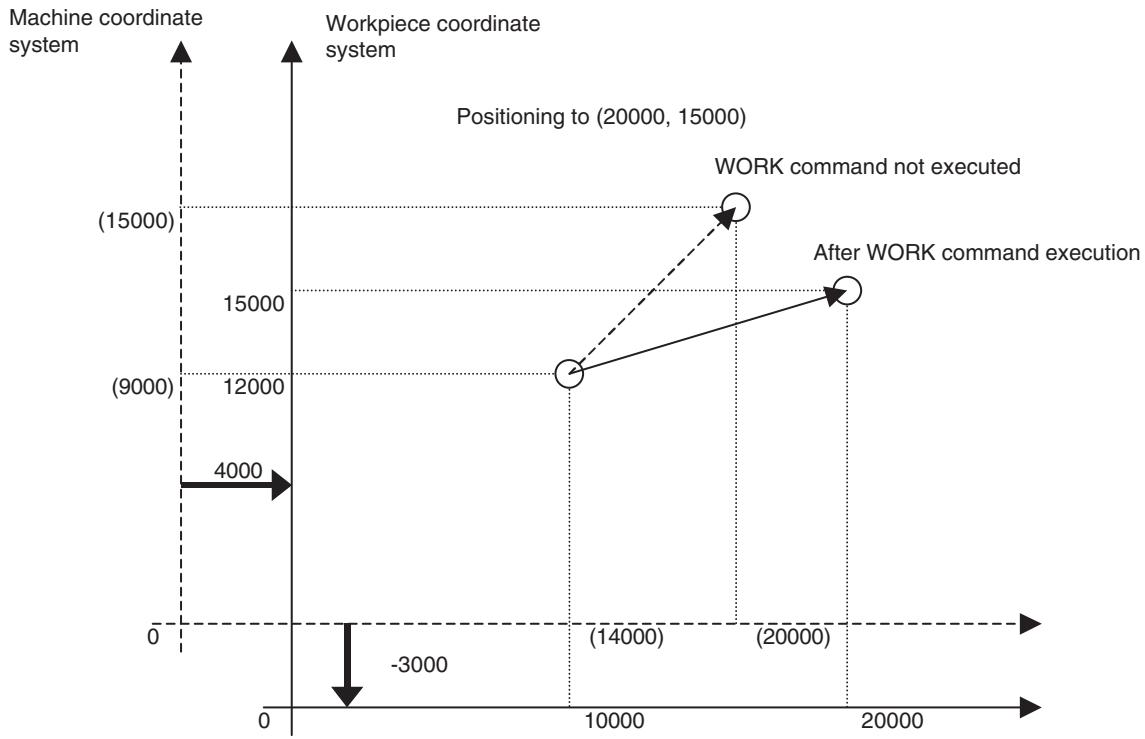
Workpiece Coordinate System Offset Change (OFFPOS)
The offset value of the workpiece coordinate system is changed.
Command type
Multiple execution command
Format
OFFPOS_C
Ex: OFFPOS_C1 [J01]10.00 [J02]-100.00;
Operand
| Operand | Setting range | Decimal | Variable specification | INC/ABL influence | ||||
| Bit | Word | Long word | Real number | Indirect specification | ||||
| Workpiece coordinate system number | 1, 2, or 3 | No | No | Yes (See note 1.) | Yes | Yes (See note 2.) | Yes | No |
| Workpiece coordinate system offset value | -2147483648 to 2147483647 | Yes | No | Yes (See note 1.) | Yes | Yes (See note 3.) | Yes | No (See note 3.) |
Note
(1) Word data is extended to long word data with a sign in the MC Unit.
(2) Figures below the decimal point are to be omitted.
(3) The actual value is determined by the setting value of the parameter [P5AA02: Position command decimal point position].
(4) There is no influence. INC specification is always used.
Description
- Offset value of the workpiece coordinate system is changed.
-
The offset amount between the machine coordinate system origin and the workpiece coordinate system origin is specified in Workpiece coordinate system offset value.
-
The workpiece coordinate system offset value specified will be enabled when WORK command is executed. It means that the offset value will not be reflected in the operation until WORK command is executed again when using the coordinate system specified with Workpiece coordinate system number.
- Workpiece coordinate system offset value specified will stay enabled until OFFPOS command is executed again.
Present Position Latch (LATCH)
The present position of the specified axis is stored.
Command type
Single execution command
Format
Axis name: J01 to J32
| Operand | Setting range | Decimal | Variable specification | INC/ABL influence | ||||
| Bit | Word | Long word | Real number | Indirect specification | ||||
| Latch position storing variable | R/W variable address | No | No | No | Yes | No | No | No |
| Latch check start position | -2147483648 to 2147483647 | Yes | No | Yes (See note 1.) | Yes | Yes (See note 2.) | Yes | No (See note 3.) |
| Latch check end position | -2147483648 to 2147483647 | Yes | No | Yes (See note 1.) | Yes | Yes (See note 2.) | Yes | No (See note 3.) |
Note
(1) Word data is extended to long word data with a sign in the MC Unit.
(2) The actual value is determined by the setting value of the parameter [P5AA02: Position command decimal point position].
(3) There is no influence. ABL specification is always used.
Description
- The position of the specified axis is stored.
- The latched position is assigned in Latch position storing variable.
- Latch signal is accepted only in the sections specified in Latch check start position and Latch check end position.
- The latch position assigned in Latch position storing variable, Latch check start position, and Latch check end position are values on the coordinate system currently being selected.
- Present position latch is performed as shown below depending on the relations between Latch check start position and Latch check end position.
| Specification | Operation | |||
| Both start position and end position are omitted | Accepting section is not specified. | |||
| Lower limit | Upper limit | |||
| Start position is omitted | Accepting section: Start position and after | |||
| Lower limit Start position | Upper limit | |||
| Specification | Operation | |||
| End position is omitted | Accepting section: End position and before | |||
| Lower limit End position Upper limit | ||||
| Start position<End position | Accepting section: Start position and after, End position and before | |||
| Lower limit Start position End position Upper limit | ||||
| Start position>End position | Accepting section: End position and before, Start position and after | |||
| Lower limit End position Start position Upper limit | ||||
| Start position = End position | Ends latch check operation being executed | |||
| Lower limit Upper limit | ||||
Note Both lower and upper limits indicate the lower and upper limits of each coordinate system.
- The latch check operation is ended by one of the following operations:
- LATCH command is executed as Latch check start position = Latch check end position
- END Command execution
- LATCH command execution will be completed when latch check operation is started.
- It may take 260ms max. (Latch startup time) until the MC Unit becomes able to actually accept the latch signal after starting LATCH command.
Note For details, see Appendix A Performance Calculation Method for the Counter Latch Startup Time on page 666.
-
As shown below, it takes the following time periods until the MC Unit becomes able to accept another LATCH command after completion of a LATCH command:
-
When Unit cycle: Communication cycle = 1: 1 6 × Unit cycle
-
When Unit cycle: Communication cycle = 2:1 4 × Unit cycle
-
Do not restart the MC Unit, or restore power only to the MC unit (including temporary power interruption) when the Unit is waiting for a latch signal after executing LATCH command in which the latch check position has been specified. When Latch check start/end positions are specified in LATCH command, the motor parameters [900A: Latch range (+) No.] and [900B: Latch range (-) No.] in the servo driver will be automatically updated. Restarting the MC Unit or restoring power only to the MC unit (including temporary power interruption) at this point will not bring back the parameter settings before being updated. In addition, executing an origin search, etc. using a latch signal under this condition may cause the axis to operate in an unexpected way since the latch signal input outside of the latch check range cannot be detected.
-
Especially, be cautious of temporary power interruption since it is impossible to know when it happens. Should it happen on the MC unit, make sure to clear the latch check range by setting the servo driver so that its power is also restored when it happens, or by using the following programs when restarting the MC Unit:
1,2,3... 1. Execute the program that only clears the latch check range:
Execute LATCH command to clear the range (Example 1)
PROG Pxxx Qxxxxxxxx; Program started
LATCH [Jxx] #xxxxxxxx; Latch range cleared (Latch resource acquired)
END; Program completed (Latch resource released)
Execute PARAM command to clear the range (Example 2)
PROG Pxxx Qxxxxxxxx; Program started
PARAM [Jxx]820 = 0; Servo parameter positive latch possible range cleared
PARAM [Jxx]822 = 0; Servo parameter negative latch possible range cleared
END; Program completed
- Add a command that intentionally clears the range before executing origin search, etc.:
Execute LATCH command to clear the range (Example 3)
LATCH [Jxx] #xxxxxxxx; Latch range cleared (latch resource acquired)
LATCH [Jxx] #xxxxxxxx 10 J0; Latch resource released
DATUM [Jxx]; Origin search
Execute PARAM command to clear the range (Example 4)
PARAM [Jxx]820 = 0; Servo parameter positive latch possible range cleared
PARAM [Jxx]822 = 0; Servo parameter negative latch possible range cleared
DATUM [Jxx]; Origin search
Single Block Ignored (NSTOP)
In single block mode, the block specified with NSTOP command does not stop at the end of the block and proceeds to the next block.
Command type
Not executed as an independent command (no type).
Format
NSTOP_
Ex: NSTOP_MOVE [J01]100.00 [J02]-300.00;
Operand
Nil
Description
- In single block mode, the block with NSTOP command at the beginning does not stop at the end of the block and proceeds to the next block.
- When the motion task control bit [Block stop] is turned ON, stopping the operation is prioritized and the block is stopped regardless of this command's influence.
6-3-5 Control Command
Program Start (PROG)
The Program Start (PROG) command declares axes to be used in the program.
Command type
Multiple execution command
Format
PROG_P
Ex: PROG_P1000 Q0000000F;
Operand
| Operand | Setting range | Decimal | Variable specification | INC/ABL influ- ence | ||||
| Bit | Word | Long word | Real number | Indirect specifi- cation | ||||
| Program number | 0 to 1999 | No | No | No | No | No | No | No |
| Axis declaration | 00000000 to FFFFFFF [hex] | No | No | No | No | No | No | No |
Description
- Program is started and axes to be used in the program are declared.
- If this command is omitted, programs cannot be loaded.
- Axis declaration describes the 32-bit string in hexadecimal corresponding to the physical axis numbers.
Example: If physical axes J02, J03, J04, J12, and J14 are used, program [PROG P000 Q0000280E;].
| J32 | J31 | J30 | J29 | J28 | J27 | J26 | J25 | J24 | J23 | J22 | J21 | J20 | J19 | J18 | J17 | J16 | J15 | J14 | J13 | J12 | J11 | J10 | J09 | J08 | J07 | J06 | J05 | J04 | J03 | J02 | J01 |
| O | O | O | O | O | |||||||||||||||||||||||||||
| ↓ | ↓ | ↓ | ↓ | ↓ | ↓ | ↓ | |||||||||||||||||||||||||
| 0 | 0 | 0 | 0 | 2 | 8 | 0 | |||||||||||||||||||||||||
- The commands to axes are valid only if they have been issued to the declared axes (no restriction on the commands using I/O variables).
- There is no restriction on referencing the axis in such case where an axis is used as a master axis in synchronization.
- If PROG command is not present at the beginning of a program, the program cannot be loaded.
-
If the declared axis cannot be reserved due to the following reasons when motion main program is started, a warning will occur, and the motion program status bit: Start warning is turned ON.
-
Axis status bit: Command disabled/enabled is OFF.
- Axis status bit: Axis not used/used is ON.
-
Axis status bit: Manual/Automatic mode is OFF.
-
If the axis declared in a sub-program cannot be reserved when calling a motion sub-program (when the axis is used in the main program, or in the sub-program called by the same main program), the alarm [2007h: Axis reservation disable] will occur.
- The axis declared in a sub-program cannot be used for the main program that called the sub-program. The alarm [2007h: Axis reservation disable] will occur.
Program End (END)
The END command ends the main program.
Command type
Single execution command
Format
END;
Ex: END;
Operand
Nil
Description
- END command ends the main program.
-
If END command is not present in the main program, the program cannot be loaded.
-
END command cancels axis operation commands (MOVELINK/CAMBOX/CONNECT/ADDAX/SYNC/ SPEED/TORQUE) being executed.
- In execution of axis operation commands other than the above, END command execution will be completed after the axis status bits [Positioning completed] (x+32, bit06 for Axis 1) for all the axes operated with the program are turned ON (1).
- Modal data is initialized according to the default setting (motion task).
- All the axes reserved by axis declaration are released.
- End command execution will be completed when all the processing above is completed.
Sub-Program Call (GOSUB)
The specified sub-program is called.
Command type
Single execution command
Format
GOSUB_PP sub-program number
Ex: GOSUB_P500;
Operand
| Operand | Setting range | Decimal | Variable specification | INC/ABL influ- ence | ||||
| Bit | Word | Long word | Real number | Indirect specifi- cation | ||||
| Sub-program num- ber | 500 to 999 1500 to 1999 | No | No | Yes (See note 1.) | Yes | Yes (See note 2.) | Yes | No |
Note
(1) Word data is extended to long word data with a sign in the MC Unit.
(2) Figures below the decimal point are to be omitted.
Description
- Sub-programs are executed.
- Sub-programs can be nested up to 5 levels.
- If the nesting limit is exceeded, the alarm [2002h: Sub-program nesting error] will occur.
- GOSUB command execution will be completed when the operation moves to the sub-program successfully.
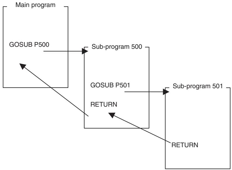
| Sub-Program End (RETURN) | Sub-program is ended. |
| Command type | Single execution command |
| Format | RETURN; Ex: RETURN; |
| Operand | Nil |
| Description | · Sub-program is ended and the operation returns to the program that called the sub-program. · If RETURN command is not present in a sub-program, the program cannot be loaded. · All the axes reserved by axis declaration are returned to the main program. · RETURN command execution will be completed when the operation returns the program that called the sub-program. |
| Dwell Time (DWELL) | The operation waits for the specified time period. |
| Command type | Single execution command |
| Format | DWELL_T<dwell time>; Ex: DWELL_T100; |
Operand
| Operand | Setting range | Decimal | Variable specification | INC/ABL influ- ence | ||||
| Bit | Word | Long word | Real number | Indirect specifi- cation | ||||
| Dwell time | 0 to 60000 | No | No | Yes (See note.) | Yes | No | Yes | No |
Note Word data is extended to long word data with a sign in the MC Unit.
Description
- The operation waits for the time period specified in Dwell time. The unit is in [ms].
- During DWELL command execution, if the motion program is stopped (except for block stop), waiting will be cancelled. When the program is resumed with the motion task control bit: [Start Mode] = 1 (resume from where the operation was stopped), waiting will be resumed for the remaining time.
- DWELL command is not an axis movement command, however, it is the cancel object of STOPOP command. When it is cancelled, waiting will be immediately cancelled and the command execution is completed.
- DWELL command execution will be completed when the specified waiting time period elapses.
Wait for Condition to be Met (WAIT) The next block will not be executed until the conditional expression is satisfied.
Command type
Multiple execution command
Format
WAIT_
Ex:WAIT_#DW0001 = = 1
The formats of conditional expressions are shown in the following table. Immediate values and variables are the only comparison objects. If a different data type is used, an alarm will occur in pre-analysis.
| Conditional Expression | Format |
| Equal to | (Immediate value or Variable) == (Immediate value or Variable) |
| Not equal to | (Immediate value or Variable)<> (Immediate value or Variable) |
| Greater than | (Immediate value or Variable)>(Immediate value or Variable) |
| Less than | (Immediate value or Variable)<(Immediate value or Variable) |
| Equal to or greater than | (Immediate value or Variable) >= (Immediate value or Variable) |
| Equal to or less than | (Immediate value or Variable) <= (Immediate value or Variable) |
Operand
Description
Nil
- The next block will not be executed until Conditional expression is satisfied.
- If the motion program is stopped (except for block stop) during WAIT command execution, waiting for condition to be satisfied is cancelled and the command execution is completed. It means that waiting will not be resumed even if it is re-started with the motion task control bit: [Start Mode] = 1 (resume from where the operation was stopped).
- DWELL command is not an axis movement command, however, it is the cancel object of STOPOP command. When it is cancelled, waiting for condition to be satisfied will be immediately cancelled and the command execution is completed.
- WAIT command execution will be completed when the conditional expression is satisfied.
- The operation when the program restarts after operation is stopped using deceleration stop or other inputs while WAIT command execution is in effect is shown in the following table.
| Unit version | Startup in start mode 1 | Startup in start mode 2 |
| Units before Unit Ver. 3.0 | Executes next block after the WAIT command. | Executes next block after the WAIT command. |
| Unit Ver. 3.0 or later | Re-executes the WAIT command. | Executes next block after the WAIT command. |
Optional End (STOPOP)
Command type
Format
If the conditional expression is satisfied, execution of the next block will be interrupted and then the block after the interrupted block will be executed.
Single execution command
STOPOP_
Ex: STOPOP_#DW0001 = = 1;
The formats of conditional expressions are shown in the following table. Immediate values and variables are the only comparison objects. If a different data type is used, an alarm will occur in pre-analysis.
| Conditional Expression | Format |
| Equal to | (Immediate value or Variable) == (Immediate value or Variable) |
| Not equal to | (Immediate value or Variable)<> (Immediate value or Variable) |
| Greater than | (Immediate value or Variable)>(Immediate value or Variable) |
| Less than | (Immediate value or Variable)<(Immediate value or Variable) |
| Conditional Expression | Format |
| Equal to or greater than | (Immediate value or Variable) >= (Immediate value or Variable) |
| Equal to or less than | (Immediate value or Variable) <= (Immediate value or Variable) |
| Operand | Nil |
| Description | If the conditional expression is satisfied, execution of the next block is interrupted. Checking the conditional expression will be completed when execution of [Block to end the operation midway] is completed. Commands that can be interrupted are all the axis movement commands, DWELL command, and WAIT command. STOPOP command execution will be completed when condition settings are completed inside the system. Ex:STOPOP #DW0001 == 1; MOVE [J01] 10000; Axis travel command #DW0002 = 1; If #DW0001 becomes 1 during execution of MOVE, MOVE is interrupted, #DW0002 is set to 1 and then the next block is executed. |
| Conditional Branching (IF ELSE ENDIF) | If the conditional expression is satisfied, processing 1 will be executed. If the conditional expression is not satisfied, processing 2 will be executed. |
| Command type | IF: Multiple execution command ELSE: Multiple execution command ENDIF: Multiple execution command |
| Format | IF_<conditional expression>; <processing 1> {ELSE; <processing 2>} ENDIF; Ex: IF #DW0001 == 1; MOVE [J01]100.00 [J02]200.00; ELSE; MOVE [J03]-100.00 [J04]-10.00; ENDIF; The formats of conditional expressions are shown in the following table. Immediate values and variables are the only comparison objects. If a different data type is used, an alarm will occur in pre-analysis. |
| Conditional Expression | Format |
| Equal to | (Immediate value or Variable) == (Immediate value or Variable) |
| Not equal to | (Immediate value or Variable)<> (Immediate value or Variable) |
| Greater than | (Immediate value or Variable)-(Immediate value or Variable) |
| Less than | (Immediate value or Variable)< (Immediate value or Variable) |
| Equal to or greater than | (Immediate value or Variable) >= (Immediate value or Variable) |
| Equal to or less than | (Immediate value or Variable) <= (Immediate value or Variable) |
Operand
Description
Nil
- If the conditional expression is satisfied, processing 1 will be executed. If the conditional expression is not satisfied, processing 2 will be executed.
- Processing 1 is described between IF and ELSE (can be described over multiple lines).
- Processing 2 is described between ELSE and ENDIF (can be described over multiple lines).
- ELSE and processing 2 can be omitted.
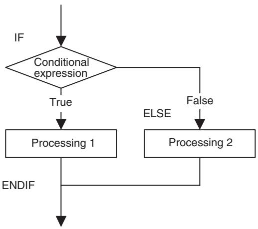
Repeat While (WHILE...WEND)
Command type
While the conditional expression is being satisfied, processing between WHILE and WEND is repeatedly executed.
WHILE: Multiple execution command
WEND: Multiple execution command
Format
WHILE_
WEND;
Ex: WHILE #DW0001 == 1;
INC MOVE [J01]100.00 [J02]200.00;
WEND;
The formats of conditional expressions are shown in the following table. Immediate values and variables are the only comparison objects. If a different data type is used, an alarm will occur in pre-analysis.
| Conditional Expression | Format |
| Equal to | (Immediate value or Variable) == (Immediate value or Variable) |
| Not equal to | (Immediate value or Variable)<> (Immediate value or Variable) |
| Greater than | (Immediate value or Variable)>(Immediate value or Variable) |
| Less than | (Immediate value or Variable)<(Immediate value or Variable) |
| Equal to or greater than | (Immediate value or Variable) >= (Immediate value or Variable) |
| Equal to or less than | (Immediate value or Variable)<= (Immediate value or Variable) |
Operand
Description
Nil
- As long as the conditional expression is being satisfied, processing between WHILE and WEND is repeatedly executed.
- Processing can be described over multiple lines.
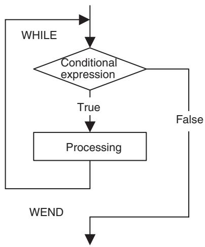
Repeat FOR (FOR...NEXT)
Processing is repeated for the specified number of times.
Command type
FOR: Multiple execution command
NEXT: Multiple execution command
Format
FOR_W
NEXT;
Ex: FOR_W#DL0002 L1000 S1;
INC MOVE [J01]100.00 [J02]200.00;
NEXT;
Operand
| Operand | Setting range | Decimal | Variable specification | INC/ABL influ- ence | ||||
| Bit | Word | Long word | Real number | Indirect specifi- cation | ||||
| Work registers for repeat count | Variable | No | No | No | Yes | No | No | No |
| Repeat end value | 1 to 2147483647 | No | No | Yes (See note 1.) | Yes | Yes (See note 2.) | Yes | No |
| Number of increment steps | -2147483648 to 2147483647 | No | No | Yes (See note 1.) | Yes | Yes (See note 2.) | Yes | No |
Note
(1) Word data is extended to long word data with a sign in the MC Unit.
(2) Figures below the decimal point are to be omitted.
Description
- Processing between FOR and NEXT will be repeatedly executed until Work resisters for repeat count becomes equal to or greater than Repeat end value.
- When decrementing (when No. of increment steps is signed "minus"), the condition will be until Repeat end value becomes equal to or greater than Work register for repeat count.
- Number of increment steps specifies the incrementing amount of Work resisters for repeat count. If negative value is set, it will be the decrementing amount.
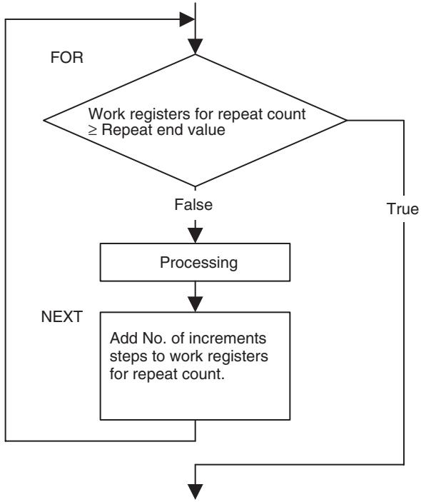
Parallel Execution (PARALLEL...JOINT... JWAIT)
Processing is branched and executed in parallel.
Command type
PARALLEL: Single execution command
JOINT: Single execution command
JWAIT: Single execution command
Format
PARALLEL_N
JOINT;
JOINT;
···
JWAIT;
Ex:PARALLEL_N2;
INC MOVE [J01]100.00 [J02]200.00;
JOINT;
ABL MOVE [J03]-100.00 [J04]-50.00;
JWAIT;
Operand
| Operand | Setting range | Decimal | Variable specification | INC/ABL influ- ence | ||||
| Bit | Word | Long word | Real number | Indirect specifi- cation | ||||
| Number of branches | 1 to 8 | No | No | No | No | No | No | No |
Description
- Processing for the number of branches specified in PARALLEL command is executed in parallel.
-
The parallel branches queue at JWAIT command and parallel branching is completed.
-
The number of parallel branches can be specified with Number of branches. The maximum number of branches for the Unit is specified in the parameter [P00002: Number of parallel branches].
If Number of branches exceeds the parameter setting, the alarm [200Dh: Count specification error] will occur. - PARALLEL command cannot be used in sub-programs. If used, the program cannot be loaded.
- END and PARALLEL commands cannot be used within processing 1, 2, and N (program end and parallel branch nesting cannot be executed inside parallel branching).
Each of processing 1, 2, and N can be described over multiple lines. - The following sequence is fixed when commands are executed in the order, processing 1, processing 2, and processing N.
- When using "PARALLEL_N1", JOINT command cannot be described.
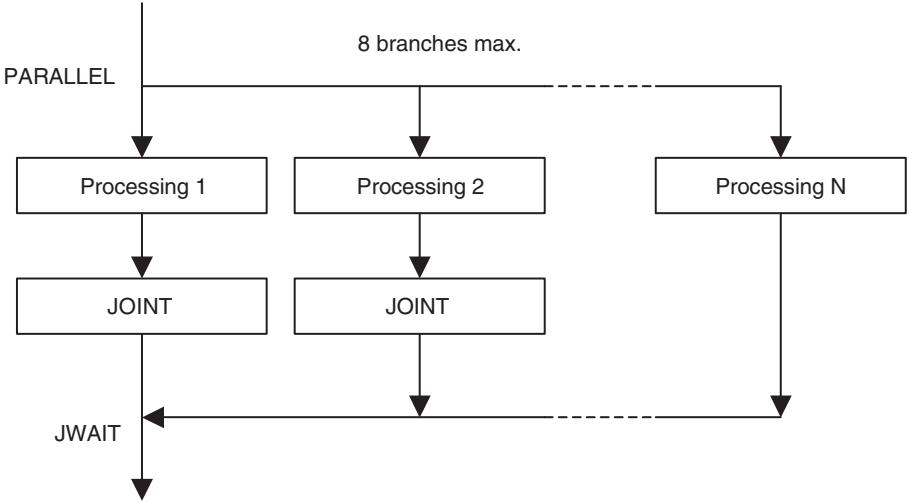
Selective Execution (SWITCH...CASE...BR EAK...SEND)
Processing is selected and executed depending on the value of the conditional variable.
Command type
SWITCH: Multiple execution command
CASE: Multiple execution command
BREAK: Multiple execution command
DEFAULT: Multiple execution command
SEND: Multiple execution command
Format
SWITCH_
{CASE_
BREAK;
CASE_
BREAK;
---}
{DEFAULT;}
SEND;
EX: SWITCH #DW0000;
CASE 0;
ABL MOVE [J03]-100.00 [J04]-50.00;
BREAK;
CASE 1;
INC MOVE [J01]-200.00 [J02]50.00;
BREAK;
DEFAULT;
INC MOVE [J01]0.00 [J02]0.00 [J03]0.00 [J05]
SEND;
Operand
| Operand | Setting range | Decimal | Variable specification | INC/ABL influ- ence | ||||
| Bit | Word | Long word | Real number | Indirect specifi- cation | ||||
| Conditional Variable | Variable | No | No | No | No | No | No | No |
| Conditional constant | Operation numerical value range | Yes | No | No | No | No | No | No |
Description
- If Conditional variable specified in SWITCH command matches Conditional constant specified in CASE command, only processing between CASE command with the matching constant and BREAK command will be executed.
- If Conditional variable does not match Conditional constant in any of CASE commands, processing between DEFAULT and SEND commands will be executed. If DEFAULT block is omitted, nothing will be executed.
- CASE command within processing 1, 2, and N is ignored, which means that the same processing can be executed under a different condition.
- There is no limit on the number of CASE commands (actually, the number of blocks per program limits it).
- SWITCH command cannot be used within processing 1, 2, and N (selective branches can not be nested).
- Processing 1, 2, and N can be described over multiple lines.
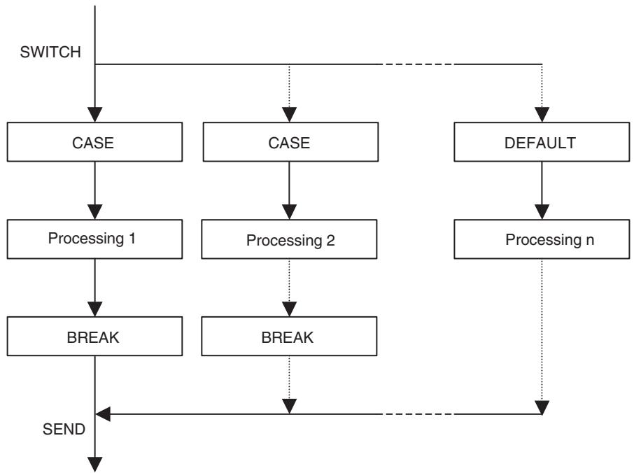
No Operation (Single) (NOPS)
No processing will occur.
Command type
Single execution command
Format
NOPS;
Ex: NOPS;
Operand
Nil
Description
- No processing will occur, however, NOPS command functions as a single execution command.
- NOPS command is used when motion program stepping has to be coordinated.
Example of Use
In positioning processes, NOPS is used when outputting data such as providing interlocking for external devices, etc. External devices indicate devices that are directly connected to the PLC or the general-purpose output of the MC unit.
The program example is shown below:
Program
PROG P0001 Q00000001; Program declared.
MOVE [J01]200000; J01 moved to the position 200000
NOPS; Block stopped till completion of single execution command MOVE
IW0B00 = 0055; Value output in Unit Cycle of MC unit next to the one where
MOVE [J01]300000; single execution command NOPS was executed
NOPS; J01 moved to the position 300000
IW0B00 = 0000; Block stopped till completion of single execution command MOVE
END; Value output in Unit Cycle of MC unit next to the one where single execution command NOPS was executed.
Timing chart
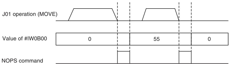
Note Without NOPS command, the value of #IW0B00 changes on the timing described below:
Program
PROG P0001 Q00000001; Program declared
MOVE [J01]200000; J01 moved to the position 200000
IW0B00 = 0055; Value output in Unit Cycle of MC unit next to the one where MOVE [J01]300000; single execution command MOVE was executed. (See note.)
IW0B00 = 0000; J01 moved to the position 300000
END; Value output in Unit Cycle of MC unit next to the one where
Single execution command MOVE was executed. (See note.)
Note Being a multiple execution command, they are output without waiting for completion of the single execution command MOVE.
Timing chart
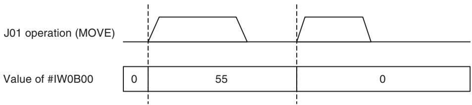
No Operation (Multiple) (NOPM)
Command type
Format
Operand
Description
No processing will occur.
Multiple execution command
NOPM;
Ex: NOPM;
Nil
- No processing will occur, however, NOPM command functions as a multiple execution command.
- NOPM command is used when motion program stepping has to be coordinated.
Example of Use
With parallel execution command, etc., NOPM command is used to match (or delayed) the timing as in starting operations of axes in the same Unit Scan, etc.
The program example is shown below:
Program
PROG P0001 Q00000001; Program declared PARALLEL N2;
PL0000 = #ILOB00 * 1000; Result of (ILOB00 x 1000) assigned to PL0000
PL0001 = #ILOB02 * 500; Result of (ILOB02 x 500) assigned to PL0001
MOVEL [J01]#PL0000 F#PL0001; J01 moved to the position PL0000 at the speed PL0001
JOINT;
PL0002 = #ILOB02 * 1000; Result of (ILOB02 x 1000) assigned to PL0002
NOPM; Stepping Adjusted for simultaneous start of [J01], [J02]
MOVEL [J02]#PL0000 F#PL0002; J02 moved to the position PL0000 at the speed PL0002
JWAIT;
END;
Timing chart
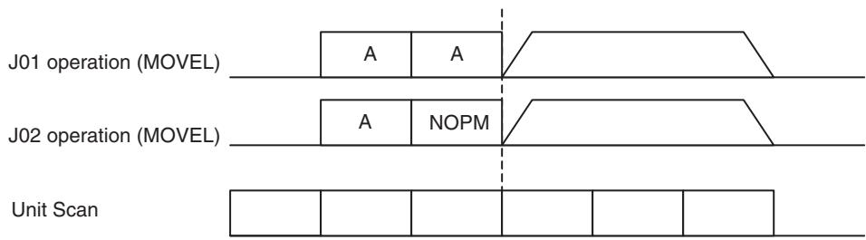
A: Assignment expression
Note Without NOPM command, [J01] and [J02] are started on the timing described below:
Program
PROG P0001 Q00000001; Program declared PARALLEL N2;
PL0000 = #ILOB00 * 1000; Result of (ILOB00 x 1000) assigned to PL0000
PL0001 = #ILOB02 * 500; Result of (ILOB02 x 500) assigned to PL0001
MOVEL [J01]#PL0000 F#PL0001; J01 moved to the position PL0000 at the speed PL0001
JOINT;
PL0002 = #ILOB02 * 1000; Result of (ILOB02 x 1000) assigned to PL0002
MOVEL [J02]#PL0000 F#PL0002; J02 moved to the position PL0000 at the speed PL0002
JWAIT;
END;
Timing chart
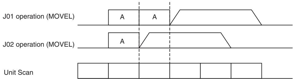
A: Assignment expression
6-3-6 Simple Arithmetic Operation
ASSIGN (=)
Values are assigned for the specified variable.
Command type
Multiple execution command
Format
Ex: #MF1000 = 123.45;
Operand
| Operand | Setting range | Decimal | Variable specification | INC/ABL influ- ence | ||||
| Bit | Word | Long word | Real number | Indirect specifi- cation | ||||
| First term | Variable | No | Yes | Yes | Yes | Yes | No | No |
| Second term | Operation numerical value range (See note.) | Yes | Yes | Yes | Yes | Yes | Yes | No |
Note Both immediate values and variables can use the values within the ranges defined for each type.
- Integer immediate value: -2147483648 to 2147483647
- Decimal immediate value: -2147483648. to 2147483647.
- Bit type: 0, 1
- Word type: -32768 to 32767
- Long word type: -2147483648 to 2147483647
Real number type: ± (1.175E - 38 to 3.402E + 38) ,0 - Indirect specification type: 0 to 10239
Description
- The value in the second term is assigned to the first term.
- If the types are different on both sides, the type on the right is converted to that of the left.
- If the value on the right side cannot be stored in the left side, the alarm [2005h: Operation overflow] will occur.
Precaution for Handling the Data Types
1,2,3... 1. Bit type
- When the bit type is used, all the operands must be the bit type.
- The integer immediate values 0 and 1 are treated as the bit type.
2. Types other than the bit type
- Types other than the bit type are prioritized in the following order Real number type > Long word type > Word type
- Operation is performed in the type of the highest priority, and the operation result will be stored after being converted to the type on the left.
- The integer immediate value is treated as long word type, and the decimal immediate value is treated as real number type.
Simple Arithmetic
Operations (+, -, *, /, %, ^)
This command executes the specified simple arithmetic operations.
Command type
+, -, *, /, %, and ^: Not executed as an independent command (no type).
Format
Ex: #MF1000 = #MF0010 + #MF0012;
Operand
| Operand | Setting range | Decimal | Variable specification | INC/ABL influ- ence | ||||
| Bit | Word | Long word | Real number | Indirect specifi- cation | ||||
| First term | Variable | No | No | Yes | Yes | Yes | No | No |
| Second term | Operation numerical value range (See note.) | Yes | No | Yes | Yes | Yes | Yes | No |
| Third term | Operation numerical value range (See note.) | Yes | No | Yes | Yes | Yes | Yes | No |
Note Both immediate values and variables can use the values within the ranges defined for each type.
- Integer immediate value: -2147483648 to 2147483647
- Decimal immediate value: -2147483648. to 2147483647.
Bit type: 0, 1 - Word type: -32768 to 32767
- Long word type: -2147483648 to 2147483647
Real number type: ± (1.175E - 38 to 3.402E + 38) ,0 - Indirect specification type: 0 to 10239
Description
- The following operators are used in operations.
| Operator | Function | Description |
| + | Add | Adds the 2nd and 3rd terms, and assigns the result to the 1st term. |
| - | Subtract | Subtracts the 3rd term from the 2nd, and assigns the result to the 1st term. |
| * | Multiply | Multiplies the 2nd and 3rd terms, and assigns the result to the 1st term. |
| / | Divide | Divides the 2nd term by the 3rd, and assigns the result for the 1st term. |
| % | Reminder | Remainder from the division of the 2nd term by the 3rd is assigned to the 1st term. |
| ^ | Exponent | Raises the 2nd and the 3rd terms, and assigns the result for the 1st. |
- If the types are different on both sides, the type on the right is converted to that of the left.
- If the value on the right side cannot be stored in the left side, the alarm [2005h: Operation overflow] will occur.
Precaution for Handling the Data Types
1,2,3... 1. Bit type
- When the bit type is used, all the operands must be the bit type.
- The integer immediate values 0 and 1 are treated as the bit type.
2. Types other than the bit type
- Types other than the bit type are prioritized in the following order: Real number type > Long word type > Word type
- Operation is performed in the type of the highest priority, and the operation result will be stored after being converted to the type on the left.
- The integer immediate value is treated as long word type, and the decimal immediate value is treated as real number type.
6-3-7 Logic Operation
Logic Operations (!, &, ~)
This specified logic operation is executed.
Command type
,\& , and : Not executed as an independent command (no type).
Format
Ex: #MW1000 = #MW0010 & #MW0011;
Operand
| Operand | Setting range | Decimal | Variable specification | INC/ABL influ- ence | ||||
| Bit | Word | Long word | Real number | Indirect specifi- cation | ||||
| First term | Variable | No | Yes (See note.) | Yes | Yes | No | No | No |
| Second term | -2147483648 to 2147483647 | No | Yes (See note.) | Yes | Yes | No | Yes | No |
| Third term | -2147483648 to 2147483647 | No | Yes (See note.) | Yes | Yes | No | Yes | No |
Note For XOR (LOGICAL EXCLUSIVE OR) () , the bit type cannot be used for variables.
Description
- The logic operation is executed with logic operators on each bit corresponding to the second and third terms. The result will be output to the bit corresponding to the first term.
| Logic operator | Function | Description |
| | | OR (LOGICAL OR) | Assigns the LOGICAL OR (OR) of the 2nd and 3rd terms to the 1st term. |
| & | AND (LOGICAL AND) | Assigns the LOGICAL AND (AND) of the 2nd and 3rd terms to the 1st term. |
| ~ | XOR (LOGICAL EXCLUSIVE OR) | Assigns the LOGICAL EXCLUSIVE OR (XOR) of the 2nd and 3rd terms to the 1st term. |
- If the types are different on both sides, the type on the right is converted to that of the left.
-
If the value on the right side cannot be stored in the left side, the alarm [2005h: Operation overflow] will occur.
-
The table below shows the result of logic operations.
| Second term | Third term | Logical OR (OR) | Logical AND (AND) | Logical exclusive OR (XOR) |
| 0 | 0 | 0 | 0 | 0 |
| 0 | 1 | 1 | 0 | 1 |
| 1 | 0 | 1 | 0 | 1 |
| 1 | 1 | 1 | 1 | 0 |
Precaution for Handling the Data Types
1,2,3... 1. Bit type
- When the bit type is used, all the operands must be the bit type.
- The integer immediate values 0 and 1 are treated as the bit type.
2. Types other than the bit type
- Types other than the bit type are prioritized in the following order: Real number type > Long word type > Word type
- Operation is performed in the type of the highest priority, and the operation result will be stored after being converted to the type on the left.
- The integer immediate value is treated as long word type, and the decimal immediate value is treated as real number type.
Logic NOT (REVERSE) (!)
This command reverses bits.
Command type
Not executed as an independent command (no type).
Format
$$ < \text {F i r s t} > =! < \text {S e c o n d} >; $$
$$ \text {E x :} # \text {M W 1 0 0 0} =! # \text {M W 0 0 1 0}; $$
Operand
| Operand | Setting range | Decimal | Variable specification | INC/ABL influ- ence | ||||
| Bit | Word | Long word | Real number | Indirect specifi- cation | ||||
| First term | Variable | No | Yes | Yes | Yes | No | No | No |
| Second term | -2147483648 to 2147483647 | Yes (See note.) | Yes | Yes | Yes | No | Yes | No |
Note Figures below the decimal point are to be omitted.
Description
- The reversed bits (NOT) on the right side are assigned to the left side.
- If the types are different on both sides, the type on the right is converted to that of the left.
- If the value on the right side cannot be stored in the left side, the alarm [2005h: Operation overflow] will occur.
Precaution for Handling the Data Types
1,2,3... 1. Bit type
- When the bit type is used, all the operands must be the bit type.
- The integer immediate values 0 and 1 are treated as the bit type.
2. Types other than the bit type
-
Types other than the bit type are prioritized in the following order: Real number type > Long word type > Word type
-
Operation is performed in the type of the highest priority, and the operation result will be stored after being converted to the type on the left.
- The integer immediate value is treated as long word type, and the decimal immediate value is treated as real number type.
6-3-8 Function
Functions
The specified function operation is executed.
The following functions can be executed; ABSOLUTE VALUE (ABS), SINE (SIN), COSINE (COS), TANGENT (TAN), ARC SINE (ASIN), ARC COSINE (ACOS), ARC TANGENT (ATAN), SQUARE ROOT (SQR), EXPONENT (EXP), NATURAL LOGARITHM (LOG), DECIMAL (FRAC), and SIGN (SGN).
Command type
ABS: Not executed as an independent command (no type).
SIN: Not executed as an independent command (no type).
COS: Not executed as an independent command (no type).
TAN: Not executed as an independent command (no type).
ASIN: Not executed as an independent command (no type).
ACOS: Not executed as an independent command (no type).
ATAN: Not executed as an independent command (no type).
SQR: Not executed as an independent command (no type).
EXP: Not executed as an independent command (no type).
LOG: Not executed as an independent command (no type).
FRAC: Not executed as an independent command (no type).
SGN: Not executed as an independent command (no type).
Format
Ex: #MF1000 = SIN #MF0010;
Operand
ABS (Absolute Value), SGN (Sign)
| Operand | Setting range | Decimal | Variable specification | INC/ABL influ- ence | ||||
| Bit | Word | Long word | Real number | Indirect specifi- cation | ||||
| First term | Variable | Yes | No | Yes | Yes | Yes | No | No |
| Second term | Operation numerical value range (See note.) | No | No | Yes | Yes | Yes | Yes | No |
SIN (SINE), COS (COSINE), ATAN (ARC TANGENT), SQR (SQUARE ROOT), EXP (EXPONENT), LOG (NATURAL LOGARITHM)
| Operand | Setting range | Decimal | Variable specification | INC/ABL influ- ence | ||||
| Bit | Word | Long word | Real number | Indirect specifi- cation | ||||
| First term | Variable | Yes | No | Yes | No | Yes | No | No |
| Second term | Operation numerical value range (See note.) | No | No | Yes | No | Yes | No | No |
TAN (TANGENT), ASIN (ARC SINE), ACOS (ARC COSINE), FRAC (DECIMAL)
| Operand | Setting range | Decimal | Variable specification | INC/ABL influ- ence | ||||
| Bit | Word | Long word | Real number | Indirect specifi- cation | ||||
| First term | Variable | Yes | No | No | No | Yes | No | No |
| Second term | Operation numerical value range (See note.) | No | No | No | No | Yes | No | No |
Note Both immediate values and variables can use the values within the ranges defined for each type.
- Integer immediate value: -2147483648 to 2147483647
- Decimal immediate value: -2147483648. to 2147483647.
Bit type: 0, 1 - Word type: -32768 to 32767
- Long word type: -2147483648 to 2147483647
Real number type: ± (1.175E - 38 to 3.402E + 38) ,0
Note that the inputs of ASIN, ACOS, and ATAN commands must be 1 or less.
- Indirect specification type: 0 to 10239
Description
- The following functional operations are executed:
| Notation | Function | Description |
| ABS | ABSOLUTE VALUE | Finds the absolute value of the specified data. |
| SIN | SINE | If the value on the right side is integer type: Input unit is [0.01deg]. The range of the specified data is -32768 to 32767 [0.01deg]. If input is outside the specified range, the alarm [200Fh: Other operand error] will occur. If the value on the right side is real number type: Input unit is [deg]. If the value on the left side is integer type: The value 10,000 times the actual result is output. If the value on the left side is real number type: The result is output as it is. |
| COS | COSINE | Finds the cosine of the specified data. If the value on the right side is integer type: Input unit is [0.01deg]. The range of the specified data is -32768 to 32767 [0.01deg]. If input is outside the specified range, the alarm [200Fh: Other operand error] will occur. If the value on the right side is real number type: Input unit is [deg]. If the value is on the left side is integer type: The value 10,000 times the actual result is output. If the value on the left side is real number type: The result is output as it is. |
| TAN | TANGENT | Finds the tangent of the specified data. The specified data is real number type only. |
| ASIN | ARC SINE | Finds the arc sine of the specified data. (Unit: [deg]) The specified data is real number type only. |
| ACOS | ARC COSINE | Finds the arc cosine of the specified data. (Units: [deg])The specified data is real number type only. |
| ATAN | ARC TANGENT | Finds the arc tangent of the specified data. (Units: [deg])The specified data is real number type only. |
| SQR | SQUARE ROOT | Finds the square root of the specified data. |
| EXP | EXPONENT | Finds the exponent of the specified data. |
| LOG | NATURAL LOG-ARITHM | Finds the natural logarithm of the specified data. (Base: e) |
| FRAC | DECIMAL | Extracts the decimal portion of the specified data. |
| SGN | SIGN | Extracts the sign of the specified data.Value of specified data ≥ 0 → 1Value of specified data < 0 → -1 |
- If the types are different on both sides, the type on the right is converted to that of the left.
- If the value on the right side cannot be stored in the left side, the alarm [2005h: Operation overflow] will occur.
Precaution for Handling the Data Types
1,2,3... 1. Bit type
- When the bit type is used, all the operands must be the bit type.
- The integer immediate values 0 and 1 are treated as the bit type.
2. Types other than the bit type
- Types other than the bit type are prioritized in the following order: Real number type > Long word type > Word type
- Operation is performed in the type of the highest priority, and the operation result will be stored after being converted to the type on the left.
- The integer immediate value is treated as long word type, and the decimal immediate value is treated as real number type.
6-3-9 Bit Operation
Specified Bit ON/OFF (SET/RESET)
According to the result of logic operation expression, the SET/RST command turns ON or OFF the specified bit of the specified variable.
Command type
SET: Not executed as an independent command (no type).
RESET: Not executed as an independent command (no type).
Format
Ex: #MB01000 = SET #MB01001 & #MB01002;
Operand)
| Operand | Setting range | Decimal | Variable specification | INC/ABL influ- ence | ||||
| Bit | Word | Long word | Real number | Indirect specifi- cation | ||||
| First term | Variable | No | Yes | No | No | No | No | No |
Description
- If the logic operation expression on the right side is true, SET command turns ON the bit specified on the left side.
-
If the logic operation expression on the right side is true, RESET command turns OFF the bit specified on the left side.
-
If the logic operation expression is false, SET or RESET command does not turn ON or OFF the specified bit.
- When the logic operation is executed on each corresponding bit with the logic operator on the right side and if there is any bit having the result of 1, it is considered to be true. On the other hand, if all the bits are 0, it is considered to be false.
Shift Right/Shift Left (SFTR/SFTL)
The Shift Right/Shift left (SFTR/SFTL) command shifts variables.
Command type
SFTR: Multiple execution command
SHTL: Multiple execution command
Format
SFTR
SFTL
Ex: SFTR #MW1000 N2;
Operand
| Operand | Setting range | Decimal | Variable specification | INC/ABL influ-ence | ||||
| Bit | Word | Long word | Real number | Indirect specifi-cation | ||||
| Shift object Variable | Variable | No | No | Yes | Yes | No | No | No |
| Shift amount | Word type (See note.): 1 to 16 Long word type (See note.): 1 to 32 | No | No | Yes | No | No | No | No |
Note Setting range varies depending on the type of the shift object.
Description
- SFTR command shifts Shift object variable to the right for the amount specified in Shift amount.
- SFTL command shifts Shift object variable to the left for the amount specified in Shift amount.
- SFTR and SFTL commands are executed only inside word or long word type variables.
6-3-10 Data Operation
BCD to BIN (BIN)
BCD data is converted into BIN data.
Command type
Not executed as an independent command (no type).
Format
Ex: #MW1000 = BIN #MW1001;
Operand
| Operand | Setting range | Decimal | Variable specification | INC/ABL influ- ence | ||||
| Bit | Word | Long word | Real number | Indirect specifi- cation | ||||
| First term | Variable | No | No | Yes | Yes | No | No | No |
| Second term | Word type: 0-9999 (See note.) Long type: 0-99999999 | No | No | Yes | Yes | No | Yes | No |
Note Setting range when viewed as BCD data.
Description
- BIN command converts the specified value (BCD data) into binary (BIN code).
- BIN command can be used only for integer data.

BIN to BCD (BCD)
The BCD command converts the BIN data into the BCD data.
Command type
Not executed as an independent command (no type).
Format
Ex: #MW1000 = BCD #MW1001;
Operand
| Operand | Setting range | Decimal | Variable specification | INC/ABL influ- ence | ||||
| Bit | Word | Long word | Real number | Indirect specifi- cation | ||||
| First term | Variable | No | No | Yes | Yes | No | No | No |
| Second term | Word type: 0-9999 (See note.) | No | No | Yes | Yes | No | Yes | No |
| Long type: 0-99999999 | ||||||||
Note Setting range when viewed as BIN data.
Description
- BCD command converts the specified value (BIN data) to BCD code.
- BCD command can be used only for integer data.

Block Transfer (XFER)
Data is transferred as a block.
Command type
Multiple execution command
Format
XFER
Ex: XFER #MW1000_#MW1100_N2;
Operand
| Operand | Setting range | Decimal | Variable specification | INC/ABL influ- ence | ||||
| Bit | Word | Long word | Real number | Indirect specifi- cation | ||||
| Transfer source first data | Variable | No | No | Yes | No | No | No | No |
| Transfer destination first data | Variable | No | No | Yes | No | No | No | No |
| Number of trans- ferred data | System vari- able:1 to (2048 - address) Global general variable:1 to (8192 - address) Input variable:1 to (4096 - address) Output vari- able:1 to (4096 - address) Task variable:1 to (128 - address) | No | No | Yes | No | No | No | No |
Description
- Data for the number of words specified in Number of transferred words is transferred from the address specified in Transfer source first data to the address specified in Transfer destination first data.
- If the transfer source and destination overlap with each other, the overlap is automatically processed and data is transferred so that it is not corrupted.
- 256 words can be transferred in one scan. If the size exceeds 256 words, it is transferred over several scans.
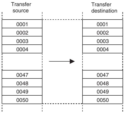
Clear (CLEAR)
The specified data is cleared to 0.
Command type
Multiple execution command
Format
CLEAR
Ex: CLEAR #MW1000_N2;
Operand
| Operand | Setting range | Decimal | Variable specification | INC/ABL influence | ||||
| Bit | Word | Long word | Real number | Indirect specification | ||||
| First cleared data | Variable | No | No | Yes | No | No | No | No |
| Number of cleared data | Global general variable:1 to (8192- address) Input variable:1 to (4096- address) Output variable:1 to (4096- address) Task variable: 1 to (128- address) | No | No | Yes | No | No | No | No |
Description
- Data for the number of words specified in Number of cleared data is cleared to 0 from the address specified in First cleared data.
- 256 words can be transferred in one scan. If the size exceeds 256 words, it is transferred over several scans.
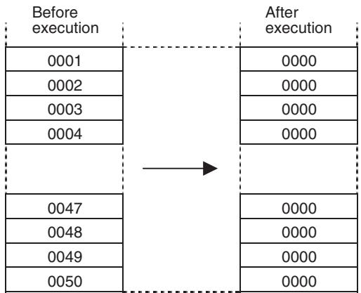
SECTION 7
PC Interface Area
This section describes the interface area in the CPU Unit used to control and monitor the CJ1W-MCH71 and CS1W-MCH71 Motion Control Units.
7-1 Overview 374
7-1-1 Data Exchange Area Overview 374
7-1-2 About I/O Refresh 375
7-1-3 Allocated Area List 375
7-1-4 CPU Unit's Influence 381
7-2 Operating Mode 382
7-2-1 Manual Mode/Automatic Mode 383
7-2-2 Manual Mode 384
7-2-3 Automatic Mode 386
7-3 Allocations for the CPU Unit 396
7-3-1 Allocations for the CPU Unit 396
7-3-2 DM Area Words for Unit (20 Words, CPU Unit MC Unit) 402
7-3-3 Custom Bit Area 411
7-3-4 Custom Data Area. 415
7-4 Interface Specifics 420
7-4-1 Unit Control Bits 420
7-4-2 Unit Status Bits 440
7-4-3 Motion Task Control Bits 443
7-4-4 Axis Control Bits, Axis Status Bits. 472
7-1 Overview
CPU Unit can control MC Unit with the following three different methods of data I/O.
1,2,3... 1. Data exchange with allocated PC area words.
- Data exchange with allocated DM area words.
- Data exchange with allocated Custom area words.
7-1-1 Data Exchange Area Overview
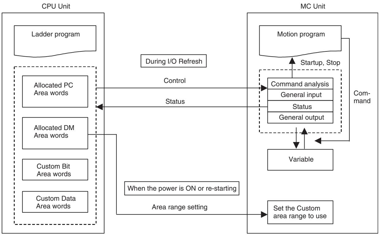
The following table shows the allocated PC interface area to be refreshed cyclically.
The number of motion tasks automatically sets the actual number of transferred words. In addition, [the area range setting] in the allocated DM area and [the physical axis setting] in axis allocation parameters determine the number of Custom area words.
| Area | Brev- ity | Direction | Usage | Remark | No. of words min. | No. of words max. |
| Allocated PC AREA words (25 words) | n | Output | Control Bit | Unit and task control | 5 | 12 |
| Input | Status Bit | Unit and task status | 6 | 13 | ||
| Allocated DM Area words (100 words) | m | Output | Area range setting (Ini- tial setting) | Only first time | 20 | 20 |
| Output | Control Data | Task control | 4 | 18 | ||
| Input | Status Data | Unit and task status | 8 | 36 | ||
| Custom Bit Area | x | Output | Control Bit | Axis control | 0 | 32 |
| Input | Status Bit | Axis status | 0 | 32 | ||
| Custom Data Area | d | Output | Control Data | Axis control | 0 | 32 |
| Input | Status Data | Axis status | 0 | 96 | ||
| Custom I/O Area | a_A | Setting | General I/O A | General I/O | 0 | 160 |
| a_B | Setting | General I/O B | General I/O | 0 | 160 | |
| a_C | Setting | General I/O C | General I/O | 0 | 160 | |
| a_D | Setting | General I/O D | General I/O | 0 | 160 | |
| a_E | Setting | General I/O E | General I/O | 0 | 160 | |
| a_F | Setting | General I/O F | General I/O | 0 | 160 | |
| a_G | Setting | General I/O G | General I/O | 0 | 160 | |
| a_H | Setting | General I/O H | General I/O | 0 | 160 | |
| 23 (See note 1.) | 1551 (See note 2.) | |||||
Note
(1) The total number of words (in a normal operation) when No. of motion tasks = 1 , No. of Axes = 1 , and without custom area allocations
(2) The total number of words (in a normal operation) when No. of motion tasks = 8 , No. of Axes = 32 , and all of general I/O are allocated
7-1-2 About I/O Refresh
When the CPU Unit's Cycle Time is shorter than the MC Unit's Unit Cycle
CPU and MC Units exchange various data mentioned above (allocated bits, allocated DM, custom bit area, etc.) with each other asynchronously. Therefore, the following behaviors may be encountered.
Data will be notified to the MC Unit after the CPU Unit runs for several cycles. Therefore, it is required to prepare the ladder program to confirm that data has been notified from the CPU Unit to the MC Unit successfully.
Ex: Turn ON the origin search bit and then confirm that the busy flag of the axis is turned ON.
When the CPU Unit's Cycle Time is longer than the MC Unit's Unit Cycle
Data will be notified to the MC Unit after the CPU Unit runs for 1 cycle.
When the CPU Unit's Cycle Time and the MC Unit's Unit Cycle are exactly the same
There is a possibility that none of data is notified to the MC Unit. In this case, set a longer or shorter Cycle Time for the CPU Unit.
7-1-3 Allocated Area List
Word Allocation Based on the Unit Number
The bit area and the range of respective DM areas are allocated based on the unit number of the Unit.
| Brevity codes | Addresses in the CPU unit | |
| n | CPU Bus Unit allocated bit area words | Word 1500 – 1899 n = 1500 + 25 × Unit Number |
| m | CPU Bus Unit allocated DM area words | D30000 – D31599 m = D30000 + 100 × Unit Number |
CPU Bus Unit Allocated Bit Area Words
25 words are allocated for each Unit starting from the word 1500.
| Unit Number | Bit area | Unit Number | Bit area |
| 0 | Word 1500-1524 | 8 | Word 1700-1724 |
| 1 | Word 1525-1549 | 9 | Word 1725-1749 |
| 2 | Word 1550-1574 | 10 | Word 1750-1774 |
| 3 | Word 1575-1599 | 11 | Word 1775-1799 |
| 4 | Word 1600-1624 | 12 | Word 1800-1824 |
| 5 | Word 1625-1649 | 13 | Word 1825-1849 |
| 6 | Word 1650-1674 | 14 | Word 1850-1874 |
| 7 | Word 1675-1699 | 15 | Word 1875-1899 |
CPU Bus Unit Allocated DM Area Words
100 words are allocated for each Unit starting from D30000.
| Unit Number | DM area | Unit Number | DM area |
| 0 | D30000-30099 | 8 | D30800-30899 |
| 1 | D30100-30199 | 9 | D30900-30999 |
| 2 | D30200-30299 | 10 | D31000-31099 |
| 3 | D30300-30399 | 11 | D31100-31199 |
| 4 | D30400-30499 | 12 | D31200-31299 |
| 5 | D30500-30599 | 13 | D31300-31399 |
| 6 | D30600-30699 | 14 | D31400-31499 |
| 7 | D30700-30799 | 15 | D31500-31599 |
CPU Bus Unit Restart Flag
When starting CPU Bus Unit, turn it OFF once, and then ON again. It will automatically turn OFF after restart processing is completed. The respective bits correspond to the unit numbers.
| Word No. | Bit No. | Function |
| A501 | 00-15 | CPU Bus Unit Restart Flag |
The Unit can be restarted using restored data simply by turning ON the CPU Unit Restart Flag (A50100 to A50115). There is no need to reset the power supply after restoring the data using the CPU easy backup function.
Standby for Unit Startup
These bits turn ON when the CPU Bus Unit is in the initial processing. The respective bits correspond to the unit numbers.
| Word No. | Bit No. | Function |
| A302 | 00-15 | CPU Bus Unit Initializing Flag |
Custom Area Allocation
It is possible to allocate custom areas regardless of the unit numbers.
These areas are allocated through [Area range setting] in the allocated DM area words.
The area range setting is used when the power is turned ON for the first time. Therefore, if changed afterwards, it will be ignored. The change will be enabled at the next power ON.
| Area | Brevity | CPU Unit's Addresses | |
| Custom Bit Area | x | Depends on Unit area range setting (m+0, m+1) | CIO, WR |
| Custom Data Area | d | Depends on Unit area range setting (m+2, m+3) | CIO, WR, DM, EM |
| Custom I/O Area | a_A | Depends on the general I/O area range setting. Unit version 2.0 or earlier: m+4 and m+5 Unit version 2.1 or later: m+4, m+5, m+74, and m+75 | CIO, WR, DM, EM |
| a_B | Depends on the general I/O area range setting. Unit version 2.0 or earlier: m+6 and m+7 Unit version 2.1 or later: m+6, m+7, m+76, and m+77 | CIO, WR, DM, EM | |
| a_C | Depends on the general I/O area range setting. Unit version 2.0 or earlier: m+8 and m+9 Unit version 2.1 or later: m+8, m+9, m+78, and m+79 | CIO, WR, DM, EM | |
| a_D | Depends on the general I/O area range setting. Unit version 2.0 or earlier: m+10 and m+11 Unit version 2.1 or later: m+10, m+11, m+80, and m+81 | CIO, WR, DM, EM | |
| a_E | Depends on the general I/O area range setting. Unit version 2.0 or earlier: m+12 and m+13 Unit version 2.1 or later: m+12, m+13, m+82, and m+83 | CIO, WR, DM, EM | |
| a_F | Depends on the general I/O area range setting. Unit version 2.0 or earlier: m+14 and m+15 Unit version 2.1 or later:m+14, m+15, m+84, and m+85 | CIO, WR, DM, EM | |
| a_G | Depends on the general I/O area range setting. Unit version 2.0 or earlier: m+16 and m+17 Unit version 2.1 or later:m+16, m+17, m+86, and m+87 | CIO, WR, DM, EM | |
| a_H | Depends on the general I/O area range setting. Unit version 2.0 or earlier: m+18 and m+19 Unit version 2.1 or later: m+18, m+19, m+88, and m+89 | CIO, WR, DM, EM | |
Allocation of Custom Bit Area and Custom Data Area
The Custom bit area (brevity code: x) and Custom data area (brevity code: d) are the areas for controls and statuses related to axes. With [Bit area type (m + 0) ] and [Data area type (m + 2) ] of [Unit area range setting] in the allocated DM area words, the area types on the CPU Unit are specified. With [Bit area first address (m + 1) ] and [Data area first address (m + 3) ], the first address of each area on the CPU Unit is specified.
Up to the words for the biggest axis number set to other than [0:Unused] in the axis allocation parameter [P1AA01: Physical axis setting] are allocated.
| Name | Function |
| Bit area type | Area type specification on the CPU Unit 0: Not used (no transfer) 1: CIO 2: WR 3 and higher: Reserved for system |
| Bit area first address | First address specification on the CPU Unit 0000H-(Upper limit varies depending on bit area type.) |
| Data area type | Area type specification on the CPU Unit 0: Not used (no transfer) 1: CIO 2: WR 3: DM 4: EM (Fix banks at 0 in the EM area) 5: and above: Reserved for system. |
| Data area first address | First address specification on the CPU Unit 0000H-(Upper limit varies depending on data area type.) |
| No. | Name | Purpose |
| P1AA01 | Physical axis setting | The greatest axis number that is going to be used determines the number of allocated. |
Custom I/O Area Allocation
The Custom I/O Areas (brevity codes: a_A to a_H) are the areas used to exchange custom data between the CPU Unit and MC Unit. In the Custom I/O Areas, there are eight general I/O areas A to H, and a size of 1 to 160 words can be specified for each area.
Note
(1) Make sure that values of the data are appropriate for operations.
(2) Make sure to confirm the safety of devices prior to changing the allocation areas.
There are two methods that can be used to allocate the customer I/O areas. Bit 8 of system parameter P00004 is used to set the method to be used.
Fixed I/O Variable Areas (P00004 Bit 8 = 0)
For general I/O area A, the number of transferred words is specified with [PORT_A No. of transferred words (bits 00 to 07 of m+4)] of [General I/O area range setting] in the allocated DM area. The area type in the CPU Unit is specified with [PORT_A Area type (bits 08 to 14 of m+4)]. In addition, the transfer direction is specified with [PORT_A Direction]. The first address in the CPU Unit is specified with [PORT_A First address (m+5)].
In the MC Unit, the custom I/O areas can be treated as I/O variables in the motion program, when the transfer direction is [MC Unit to CPU]: output variables; when transfer direction is [CPU Unit to MC Unit]: input variables.
| Area | Input variable | Output variable |
| General I/O A | IW0B00 | OW0B00 |
| General I/O B | IW0BA0 | OW0BA0 |
| General I/O C | IW0C40 | OW0C40 |
| General I/O D | IW0CE0 | OW0CE0 |
| General I/O E | IW0D80 | OW0D80 |
| General I/O F | IW0E20 | OW0E20 |
| General I/O G | IW0EC0 | OW0EC0 |
| General I/O H | IW0F60 | OW0F60 |
| Name | Function |
| PORT_A No. of transferred words | Number of words transferred for general I/O area A 1 to 160 words |
| Port_A Area type | CPU Unit area type for General I/O A: 0: Not used (no transfer). 1: CIO 2: WR 3: DM 4: EM (fixed at bank 0) 5 and higher: Reserved for system. |
| Port_A Direction | Transfer direction for General I/O A: 0: MC Unit to CPU Unit 1: CPU Unit to MC Unit |
| Port_A First Address | CPU Unit first address for general I/O A: 0000H to (Upper limit varies depending on Port_A Area type.) |
- General I/O area allocation is performed using [PORT_ Number of transferred words], [PORT_ Area type], [PORT_ Direction], and [PORT_ First address].
- The destination of allocations in the MC Unit is as follows: When [PORT_ Direction] is 0 (MC Unit to CPU): Output variables When [PORT_Direction] is 1 (CPU to MC Unit): Input variables
- The above data is valid only during PC21 bus initialization. It will be ignored if it is changed after the power is already ON.
Custom I/O Variable Areas (P00004 Bit 8 = 1) (Unit Ver. 2.1 or Later)
As shown in the following table, general I/O areas A to H can be allocated to any variables in the MC Unit.
| Area | Variables |
| General I/O A | Variable areas and custom addresses can be set for the following variables. |
| General I/O B | • System variables • Global general variables • Input variables • Output variables • Position data • Task variables |
| General I/O C | |
| General I/O D | |
| General I/O E | |
| General I/O F | |
| General I/O G | |
| General I/O H |
For general I/O area A, the number of transferred words is specified with [PORT_A No. of transferred words (bits 00 to 07 of m+4)] of [General I/O area range setting] in the allocated DM area, just as when P00004 bit 8 is set to 0. The area type in the CPU Unit is specified with [PORT_A Area type (bits 08 to 14 of m+4)]. In addition, the transfer direction is specified with [PORT_A Direction]. The first address in the CPU Unit is specified with [PORT_A First address (m+5)].
| Name | Function |
| PORT_A No. of transferred words | Number of words transferred for general I/O area A 1 to 160 words |
| Port_A Area type | CPU Unit area type for General I/O A: 0: Not used (no transfer). 1: CIO 2: WR 3: DM 4: EM (fixed at bank 0) 5 and higher: Reserved for system. |
| Port_A Direction | Transfer direction for General I/O A: 0: MC Unit to CPU Unit 1: CPU Unit to MC Unit |
| Port_A First Address | CPU Unit first address for general I/O A: 0000H to (Upper limit varies depending on Port_A Area type.) |
For general I/O area A in the MC Unit, allocations are specified by setting the [PORT_A transfer area type at MC Unit] (m + 74) and the [PORT_A transfer first address at MC Unit] (m + 75) of [General I/O area range setting] in the allocated DM area.
| Meaning | Word | Bits | Name | Function |
| General I/O A area range setting (first time only) at MC Unit | m+74 | 00 to 15 | PORT_A transfer area type at MC Unit | General I/O A area transfer area type at MC Unit (hexadecimal) 0000: System variables 0001: Global general variables 0002: Input variables 0003: Output variables 0004: Position data 0005: Reserved 0006: Task variable 1 0007: Task variable 2 0008: Task variable 3 0009: Task variable 4 000A: Task variable 5 000B: Task variable 6 000C: Task variable 7 000D: Task variable 8 Other: Reserved |
| m+75 | 00 to 15 | PORT_A transfer first address at MC Unit | General I/O area A first address of transfer source at MC Unit (hexadecimal) System variables 0000-07FF Global general variables 0000-1FFF Input variables 0000-0FFF Output variables 0000-0FFF Position data 0000-27FF Task variables 0000-007F | |
| General I/O B to H area range setting (first time only) at MC Unit | m+76 to m+89 | --- | Same as General I/O A area range setting | Same as General I/O A area range setting |
Note m: DM Area for CPU Bus Unit words D30000 to D31599 (100 words per Unit according to Unit No.)
Relationship between MC Unit Transfer Area Type, Transfer First Address, and Number of Transfer Words
The following combinations cannot be transferred. If these combinations are specified, the data will not be transferred, but an error will not occur.
1,2,3... 1. Writing data from the CPU Unit to the MC Unit system variables
- Writing data from the CPU Unit to the MC Unit output variables (OW0300 to OW04FF)
- Transferring data to an unsupported area (write/read: Examples 2 and 3 in following diagram)
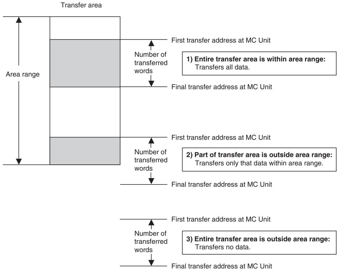
Observe the following points when transferring position data for the MC Unit.
- Position data consists of two words. Therefore, specify twice the number of words to be transferred to the CPU Unit. If an odd number is specified, the final word will be discarded when the data is transferred.
- Specify position data addresses in the format PLxxxx.
Example: If 160 words of position data are transferred from PL0000, the data from PL0000 to PL004F (80 items) will be transferred.
7-1-4 CPU Unit's Influence
CPU Unit Operating Mode Change
CS/CJ-series CPU Units have the following three operating modes:
1,2,3...
- RUN Mode
Programs can be executed normally.
- MONITOR Mode
Programs can be executed normally. Data saved in the memory can be modified.
- PROGRAM mode
Programs cannot be executed. Programming and debugging are possible.
The MC Unit operates as shown in the table below when the operating mode of the CPU Unit is changed:
| CPU Unit operating mode change | MC Unit operation |
| RUN Mode or MONITOR Mode → PROGRAM Mode | All the axes decelerate and stop. *Note that, however, there will be no influence on the MC Unit operation when the MC Unit is in Tool Mode. (The CPU Unit does not control the MC Unit in Tool Mode.) |
| Other than the above | There is no influence on the MC Unit operation. |
CPU Unit Status
The MC Unit operates as shown in the table below when the CPU Unit is in the following state:
| CPU Unit status | MC Unit operation |
| CPU Unit fatal error: An error such as memory error occurred during operation and the operation cannot be continued. | ·When “CPU stopping” is notified, Servo OFF (See note.) is executed. ·This error is stored in the error log. ·From this point on, no commands can be accepted from the CPU Unit. Note that, however, various operations can be received from the Support Tool. (Event communications can be used.) |
| Load rejection: Load is rejected from applications in debugging. | ·When “Load rejection” is notified, the MC Unit interprets all the inputs from the CPU Unit as all “0”. Due to this, the program operation, the JOG operation, and so on, decelerate and stop. |
| Bus error: | ·When the Bus error is detected, Servo OFF (See note.) is executed. ·The error is stored in the error log. ·From this point on, no commands can be accepted. |
| CPU WDTUP: | ·When “WDT UP” is detected, the same processing as for CPU Unit fatal error is executed. |
| Power interruption: | ·When “Power interruption” is detected, Servo OFF (*1) is executed. ·From this point on, no commands can be accepted. |
| CPU standby: (When CPU Unit is turned ON) | ·This is ignored because there is no influence on execution of MC Unit functions. |
| Restarting CPU Bus Unit during operation ·User turned ON AR ·Routing table transfer (communication unit) | ·When Restart is detected, Servo OFF is executed on all the tasks and axes. ·After that, the same processing as for powering ON is executed. |
| Verification error: When CPU Unit is turned ON | ·“Verification error” is notified. ·The error is stored in the error log. ·From this point on, no commands can be accepted. |
Note Output signals will not change even when Servo OFF is executed.
7-2 Operating Mode
This section describes the MC Unit internal modes, the function for controlling the MC Unit from the CPU Unit using manual/automatic modes, and CPU Unit ladder programming.
MC Unit Internal Modes
The MC Unit has three internal modes: RUN, CPU and Tool Modes.
All operations (manual mode/automatic mode) can be performed from the CPU Unit in RUN and CPU Modes.
| Internal mode | Description | Operation from CPU Unit | |
| Manual Mode | Automatic Mode | ||
| RUN Mode | This is the normal mode for operating the MC Unit from the CPU Unit. The MC Unit will be in RUN Mode when the power is turned ON. When MC Unit is in RUN Mode, the Support Tool can use read functions only, e.g., it can read programs and parameters and monitor present values. | All commands can be used. | All commands can be used. |
| CPU Mode | This mode is used for debugging with the MC Unit operated from the CPU Unit. Switch to this mode using the Support Tool. Program read/write, parameter read/write, and other editing functions (read/write) can be used from the Support Tool and present values can be monitored in this mode. Data cannot be saved to flash memory, however, from the Support Tool. | All commands can be used. | All commands can be used. |
| Tool Mode | This mode is used for debugging with the MC Unit operated from the CPU Unit. Switch to this mode using the Support Tool. No operations can be performed from the CPU Unit when in this mode. Only commands from the Support Tool are accepted. All functions can be used from the Support Tool when in this mode, and present values can be monitored, i.e., program read/write, parameter read/write, other editing functions (read/write), and save to flash memory. | Not all commands can be used. All MC Unit status data is refreshed as normal. | Not all commands can be used. All MC Unit status data is refreshed as normal. |
7-2-1 Manual Mode/Automatic Mode
- There are two types of operating modes for MC Unit; one is Manual Mode and another is Automatic Mode.
- The bit [Manual/Automatic mode] in the allocated bit area switches the mode between Automatic and Manual.
- The mode can be set for each axis. ON (1) is Automatic Mode and OFF (0) is Manual Mode.
- In Manual Mode, operations of the MC Unit are controlled directly from the CPU Unit using the PC interface areas.
- In Automatic Mode, motion programs programmed with the motion language are executed.
Whether function can or cannot be executed in each operating mode
| Function | Command method | Manual Mode | Automatic Mode |
| Axis Alarm Reset | Axis control bit | Yes | Yes |
| Deceleration Stop | Axis control bit | Yes | No |
| Servo Lock | Axis control bit | Yes | Yes |
| Servo Unlock | Axis control bit | Yes | Yes |
| JOG | Axis control bit | Yes | No |
| STEP | Axis control bit | Yes | No |
| Origin Search | Axis control bit | Yes | No |
| Machine Origin Return | Axis control bit | Yes | No |
| Error Counter Reset | Axis control bit | Yes | Yes |
| Forced Origin | Axis control bit | Yes | No |
| ABS Origin Setting | Axis control bit | Yes | No |
| Axis Override Enable | Axis control bit | Yes | Yes |
| JOG/STEP Direction | Axis control bit | Yes | No |
| Axis Machine Lock | Axis control bit | Yes | Yes |
| Manual/Automatic Mode | Axis control bit | Yes | Yes |
| Present Position Preset | IOWR instruction | Yes | No |
Yes: Can be executed
No: Cannot be executed
7-2-2 Manual Mode
In Manual Mode, control for each axis is possible and the following functions can be executed.
Each function can be enabled and executed when the corresponding bit is turned ON. If 2 or more bits are turned ON (1) simultaneously, the processing will proceed following the priority shown below:
| Priority | Name of bits | Specification |
| High | Servo Unlock | Cancels Servo lock status. |
| Deceleration Stop | Decelerates to stop (JOG, STEP, Origin search, Machine origin return). | |
| Axis Alarm Reset | Cleared the alarm occurring on the axis level and MLK slave alarm. | |
| Error Counter Reset | Resetsethe error counter (Position command value = present position). | |
| STEP | Starts STEP operation (PTP operation for debugging). | |
| JOG | Starts JOG operation. | |
| Machine Origin Return | Starts machine origin return (PTP). | |
| Origin Search | Starts origin search. | |
| Forced Origin | Defines the present position as the origin on the machine coordinate system. | |
| Present Position Preset(IOWR) | Changes the present position to the specified value. | |
| ABS Origin Setting | Sets the origin of the ABS encoder. | |
| Low | Servo Lock | Starts the servo lock status. |
The following functions can be executed simultaneously with other functions:
| Name of bits | Specification |
| Axis Override Enable | Enables the axis override value. |
| JOG/STEP Direction | Specifies the JOG, and STEP operation direction. |
| Axis Machine Lock | Starts axis machine lock. |
| Manual/Automatic Mode | Switches between Manual and Automatic modes. |
Whether another function can or cannot be executed during execution of a function
The following table shows whether another function can or cannot be executed when a function listed vertically on the left are being executed:
Yes: Can be executed No: Cannot be executed (Ignored)
| Function currently being executed | Function to be executed along with the function currently being executed. | |||||||||||
| Servo Unlock | Deceleration Stop | Axis Alarm Reset | Error Counter Reset | STEP | JOG | Machine Origin Return | Origin Search | Forced Origin | Present Position Preset | ABS Origin Setting | Servo Lock | |
| Servo Unlock | --- | No | Yes | Yes | No | No | No | No | No | No | No | No |
| Deceleration Stop | Yes | --- | Yes | Yes | No | No | No | No | No | No | No | No |
| Axis Alarm Reset | Yes | No | --- | Yes | No | No | No | No | No | No | No | No |
| Error Counter Reset | Yes | Yes | Yes | --- | No | No | No | No | No | No | No | No |
| STEP | Yes | Yes | Yes | Yes | --- | No | No | No | No | No | No | No |
| JOG | Yes | Yes | Yes | Yes | No | --- | No | No | No | No | No | No |
| Machine Origin Return | Yes | Yes | Yes | Yes | No | No | --- | No | No | No | No | No |
| Origin Search | Yes | Yes | Yes | Yes | No | No | No | --- | No | No | No | No |
| Forced Origin | Yes | No | Yes | Yes | No | No | No | No | --- | No | No | No |
| Present Position Preset (IOWR) | Yes | No | Yes | Yes | No | No | No | No | No | --- | No | No |
| ABS Origin Setting | Yes | No | Yes | Yes | No | No | No | No | No | No | --- | No |
| Servo Lock | Yes | No | Yes | Yes | No | No | No | No | No | No | No | --- |
During execution of the following functions, the Busy flag will be turned ON. After execution of a function, turn the bit OFF, check if the BUSY flag is OFF, and then execute the other functions.
- Error counter reset, STEP, JOG, Machine origin return, Origin search, Forced origin, and ABS origin setting
The following table shows whether deceleration stop can be executed or not and whether the Busy flag turns ON or stays OFF when the functions listed vertically on the left are being executed. Additionally, whether the functions listed vertically on the left can be executed under various conditions or not is shown:
| Function | Condition | ||||||||||||
| Interruptibl by deceleration stop | BUSY ON/OFF | Restriction due to status:Yes: Can be executedNo: Cannot be executed | Restriction due to communicationsYes: Can be executedNo: Cannot be executed | ||||||||||
| Automatic Mode ON | BUSY ON | Axis Operating ON | No Origin ON | Axis Alarm Occurring | Servo Unlock | Other stop request ON | Positioning Completed OFF | Virtual axis | Not a Servo axis | Command Disabled/Enabled OFF | |||
| Axis Alarm Reset | No | OFF | Yes | Yes | Yes | Yes | Yes | Yes | Yes | Yes | Yes | Yes | |
| Deceleration Stop | --- | OFF | No | Yes | Yes | Yes | Yes | Yes | Yes | Yes | No | No | |
| Servo Lock | No | OFF | Yes | Yes | Yes | Yes | No | Yes | Yes | Yes | Yes | No | |
| Servo Unlock | No | OFF | Yes | Yes | Yes | Yes | Yes | Yes | Yes | Yes | No | No | |
| JOG | Yes | ON | No | No | Yes | Yes | No | No | No | Yes | Yes | No | |
| STEP | Yes | ON | No | No | Yes | Yes | No | No | No | Yes | Yes | No | |
| Origin Search | Yes | ON | No | No | Yes | Yes | No | No | No | Yes | Yes | No | |
| Machine Origin Return | Yes | ON | No | No | Yes | No | No | No | No | Yes | Yes | No | |
| Error Counter Reset | No | ON | Yes | Yes | Yes | Yes | Yes | Yes | Yes | Yes | Yes | No | |
| Forced Origin | No | ON | No | No | No | Yes | No | Yes | No | No | Yes | No | |
| ABS Origin Setting | No | ON | No | No | No | Yes | No | Yes | No | No | No | No | |
| Axis Override Enable | No | OFF | Yes | Yes | Yes | Yes | No | No | No | Yes | Yes | No | |
| JOG/STEP Direction | No | OFF | No | No | Yes | Yes | No | No | No | Yes | Yes | No | |
| Axis Machine Lock | No | OFF | Yes | Yes | Yes | Yes | Yes | Yes | Yes | Yes | No | No | |
| Manual/Automatic Mode | No | OFF | Yes | Yes | Yes | Yes | Yes | Yes | Yes | Yes | Yes | Yes | |
| Present Position Preset (IOWR) | No | OFF | No | No | No | Yes | No | Yes | No | Yes | Yes | No | |
7-2-3 Automatic Mode
- In Automatic Mode, motion programs programmed with the motion language are executed.
- Follow the procedure below to execute the motion program in Automatic Mode.
- In this example, Axis 1 is operated with Motion task 1.
1,2,3... 1. Set the MC Unit to Automatic Mode.
To specify the axis to be used in the program, turn ON the axis control bit [Manual/Automatic mode (15 bits of word x + 0 )].
- Specify the program number to be executed.
Set the program number to be executed in the motion task control data [Motion program number (word m+22)] of motion task control data.
- Set the Start Mode for restarting the motion program interrupted in the middle of execution. (See note.)
Set the mode in the axis control bit [Start Mode (01 and 02 bits of word n+4)].
- Start the program.
Turn ON the Motion task control bit [Motion program start (01 bit of word n+4)].
Note There are three different patterns to stop a motion program:
1,2,3... 1. Motion task control bit [Deceleration stop] (Interruption):
Deceleration stop is executed regardless of the block (Stopped in the middle).
- Motion task control bit [Block stop]:
Operation is stopped at the end of the block currently being executed (Block stop).
- END command is executed.
The method of resuming the interrupted motion program can be selected in the Start Mode as show in the table below.
| Start Mode | Operation |
| 0,3 | Reads the program number and execute the program from the beginning. |
| 1 | Program is executed from the block indicated by Executing Motion Block No. Operation varies depending on the command or stopping status. • Resuming motion program when executing MOVE/MOVEL/MOVEC/MOVEI/MOVET commands: The program is resumed from where it was stopped. • Resuming motion program when executing MOVETRAV/MOVELINK/CAMBOX (1 cycle) commands: When stopped midway, the program resumes for the remaining travel distance. In case of block stop, the program for the entire travel distance is executed again. • Resuming motion program when executing commands DATUM/CAM For both midway stop and block stop, the program for the entire travel distance is executed again. |
| 2 | Resumes the program from the next block of the block indicated by Executing Motion Block No. |
Details of resuming motion programs interrupted in midway of MOVE/MOVEL/MOVEC/MOVEI/MOVET command execution (in Start Mode 1 or 2) are explained in the following pages.
When a program is stopped in the middle of a block for a finite length axis
The Executing Motion Block No. indicates the block where the motion program was stopped.
In case of ABL specification
...
ABL MOVE [J1] 2000 [J2] 0; _ When this block is interrupted
ABL MOVE [J1] 3000 [J2] 0;
···
| Start Mode | Operation |
| 1 Resumes program from mid-way of the block indicated by Executing Block Number. | Start point Interruption End point Start point End point Command's track Actual track Manual intervention Restart point |
| 2 Resumes program from the next block of the one indicated by Executing Block Number. | Start point Interruption End point Start point End point Command's track Actual track Manual intervention Restart point |
In case of INC specification
INC MOVE [J1] 2000 [J2] 0; _ When this block is interrupted
INC MOVE [J1] 1000 [J2] 0;
| Start Mode | Operation |
| 1 Resumes pro-gram from mid-way of the block indicated by Executing Block Number. | Start point Interruption End point Start point End pointCommand's trackActual trackManual interventionRestart point |
| 2 Resumes pro-gram from the next block of the one indicated by Executing Block Number. | Start point Interruption End point Start point End pointCommand's trackActual trackManual interventionRestart point |
When a program is stopped in the middle of a block for an infinite length axis
The Executing Motion Block No. indicates the block where the motion program was stopped. Operation will be as described below when operation is continued in the middle of a block in start mode 1.
MC Units manufactured before 2 February 2004 (Lot No. 040202xxxx)
- Axis 1 is set to a turntable.
- Axis 1 is set as an infinite length axis.
- The command value for axis 1 is set between 0^ and 359^ .
- The following command is executed. MOVE [J01]500
- This command means to turn axis 1 once (360^) and then to position to 140^ in the second turn.
- Assume that the above command is executed, but a deceleration stop is executed at 120^ in the first turn.
- If operation is continued in start mode 1 after decelerating to a stop, axis 1 will be positioned to 140^ in the same turn (i.e., in the first turn in this example).
MC Units manufactured 2 February 2004 (Lot No. 040202xxxx) or later
The above operating modes can be combined with the MOVE, MOVEL, and MOVET commands with P00004 bit 06 (continuous operation using infinite length axis for multiple rotations) set to 1 to enable positioning to the final target position, as follows.
- Axis 1 is set to a turntable.
- Axis 1 is set as an infinite length axis.
- The command value for axis 1 is set between 0^ and 359^ .
- The following command is executed. MOVE [J01]500
- This command means to turn axis 1 once (360^) and then to position to 140^ in the second turn.
- Assume that the above command is executed, but a deceleration stop is executed at 120^ in the first turn.
- If operation is continued in start mode 1 after decelerating to a stop, axis 1 will be positioned to the final target position (i.e., to 140^ in the second turn in this example).
When a program is stopped at the end of a block
The Executing Motion Block No. indicates the block number where the motion program was stopped.
In case of ABL specification
...
ABL MOVE [J1] 2000 [J2] 0; _ When this block is interrupted
ABL MOVE [J1] 3000 [J2] 0;
···
| Start Mode | Operation |
| 1 Resumes pro- gram from mid- way of the block indicated by Exe- cuting Block Number. | Block stop Start point End point Start point End point Command's track Actual track Restart point |
| 2 Resumes pro- gram from the next block of the one indicated by Executing Block Number. | Block stop Start point End point Start point End point Command's track Actual track Restart point |
In case of INC specification
INC MOVE [J1] 2000 [J2] 0; _ When this block is interrupted
INC MOVE [J1] 1000 [J2] 0;
···
| Start Mode | Operation |
| 1Resumes pro-gram from mid-way of the block indicated by Exe-cuting Block Number. | Block stopEnd point Start point End pointCommand's trackActual trackRestart point |
| 2Resumes pro-gram from the next block of the one indicated by Executing Block Number. | Block stopEnd point Start point End pointCommand's trackActual trackRestart point |
Ladder program example to execute motion programs
The procedure to execute the motion program is described as a ladder program below.
Note that, however, the following ladder program contains the circuits of only the minimum requirements to execute a motion program. Therefore, it is necessary to add circuits depending on the actual requirement for actual operations.
Ladder Program
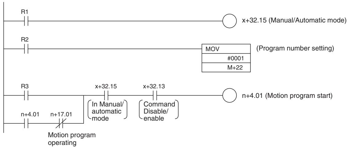
For R1 to R3, use work bits.
In this program, the program [P0001] is executed in motion task 1.
For actual operation, change the axis on which the motion program is to be executed, motion task, and program number as needed.
Turn ON R1 in order to specify Automatic Mode.
Turn ON R2 for the following conditions:
1,2,3...
- Executing a program for the first time after the power is turned ON
- Executing a program from the first block
- When the program number was changed
Turning ON R3 will start the execution.
Motion Program Operating Bit
The Motion program operating bit turns ON during program execution, and turns OFF when program execution is completed or stopped.

Motion Program Completed Bit
When a motion program is completed, the motion program completed bit turns ON (turns ON when the END command execution is completed). Even if the motion program starts on, the motion program operating bit turns OFF simultaneously when the motion program completed bit is turned ON.
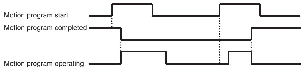
The list below is for the motion task 1. the list for motion tasks 2-8 is the same as motion task 1.
Related PC Interface Area List
| Classification | Word | Variable | bit | Name | Specifications |
| Motion task 1 Control bit | n+4 | IW0340 | 01 | Motion program start | 0: Nil1: Nil↑: Starts motion program operation following the specified Start Mode.↓: Nil |
| 02-03 | Start Mode | 0,3: Reads the program number and executes the program from the beginning.1: Executes the program from the block indicated by Executing Motion Block Number. Operation at resum-ing interrupted programs varies depending on the command used or stopping status. For details, see 7-4-3 Motion Task Control Bits (page 443).2: Executes the program continuously from the next block of the block indicated by Executing Motion Block Number. | |||
| Motion task 1 Control data | m+22 | IW0360 | 00-15 | Motion task 1 Program number | Specifies the program number to be executed in motion tasks.0-499 |
| Axis 1 Control bit | x+0 | IW0440 | 15 | Manual/Automatic mode | 0: Manual mode1: Automatic mode↑: Decelerates to stop manual operation currently being executed.↓: Decelerates to stop automatic operation currently being executed. |
| Motion task 1 Status bit | n+17 | OW0340 | 01 | Motion program operating | 0: Motion task is not executing a program operation.1: Motion task is executing a program operation. (Turned OFF after deceleration stop/block stop com-pletion) |
| 02 | Motion program completed | 0: When program operation is started.1: END command was executed. | |||
| 03 | Block being stopped | 0: Block not being stopped1: Block being stopped | |||
| 05 | Start warning | 0: Motion program started operating successfully.1: Motion program could not start operating. (Axis declaration, Axis mode) | |||
| Axis 1 Status bit | x+32 | OW0440 | 15 | In Manual/Automatic mode | 0: In Manual mode1: In Automatic mode |
Explanation of the table
0: Indicates that the bit is OFF.
1: Indicates that the bit is ON.
↑: Indicates turning ON from 0 to 1.
: Indicates turning OFF from 1 to 0.
Decimal system is applied to the other values using multiple bits.
When controlling with the rise (or fall) of the bits from the CPU Unit to the MC Unit, the change of bits is processed in the MC Unit, not in the CPU Unit. Therefore, if instructions like DIFU/DIFD are used, the change of bits may not be reflected.
Ladder Program Example and Timing Chart
Ladder program example and timing chart for the program operation with axis movement (including deceleration stop) are shown below.
In this example, Axes 1 and 2 are operated with motion task 1 and the Motion task 1 Control bit [Deceleration stop] is used for stopping.
In the timing chart, Axes 1 and 2 are operated and they are stopped with deceleration stop in midway. After that, the operation is resumed in Start Mode 1 (Program execution is executed continuously from midway of the block indicated by the Executing Motion Block Number).
Ladder program
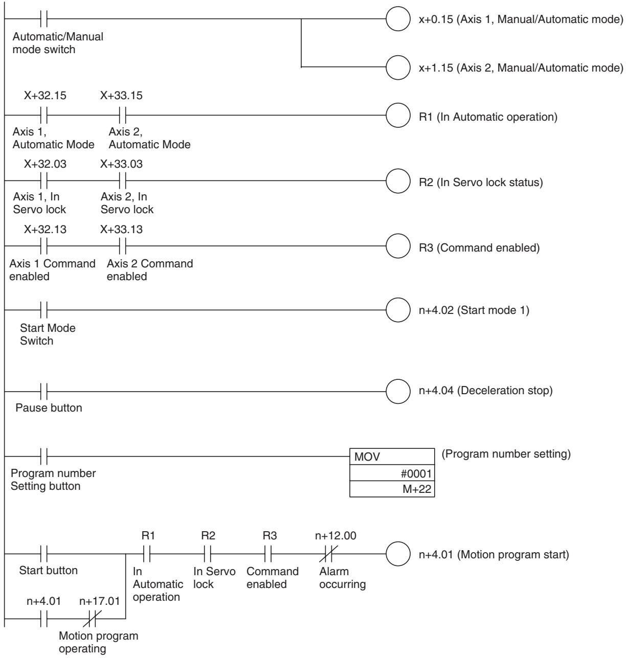
Note When executing axis movement commands in a motion program, it is required to execute Servo lock for all the applicable axes (the bit [In Servo Lock] is ON), and to set the operating mode to Automatic Mode (the bit [In Manual/Automatic mode] is ON). Therefore, make sure to insert the conditions R1 and R2 of the above ladder program.
Word Allocation Example
The word allocation for the ladder program above is shown below (Unit number: 0):
| Description in ladder program | Axis 1 | Axis 2 |
| R1 to R3 (Work bit) | W50001 to W50003 | |
| x+0.15, x+1.15 (Manual/Automatic Mode) | W20015 (See note.) | W20115 (See note.) |
| n+4.02 (Start Mode 1) | 150402 | |
| n+4.04 (Deceleration Stop) | 150404 | |
| n+4.01 (Motion Program Start) | 150401 | |
| m+22 (Program Number Setting) | DM30022 | |
| x+32.15, x+33.15 (Automatic Mode) | W23215 (See note.) | W23315 See note.) |
| x+32.03, x+33.03 (In Servo Lock) | W23203 (See note.) | W23303 (See note.) |
| x+32.13, x+33.13 (Command Enabled) | W23205 (See note.) | W23305 (See note.) |
| n+17.01 (Motion Program Operating) | 151701 | |
| n+12.00 (Alarm Occurring) | 151200 | |
| Automatic/Manual Mode Switch | 000100 | |
| Start Button | 000101 | |
| Program Number Setting Button | 000102 | |
| Pause Button | 000103 | |
| Start Mode Switch | 000104 | |
Note When setting the custom bit area from WR200, the area range for the Unit is set as shown below:
m+0 Area type specification on the CPU 0002h (WR)
m+1 Bit area first address 00C8h (200)
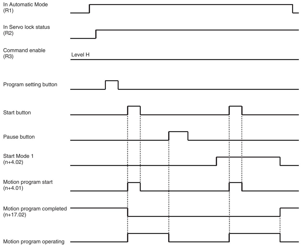
Timing Chart
MC Unit and CPU Unit Process Cycle
-
Do NOT set the same Cycle Time as the Unit Cycle of the MC Unit or the Cycle Time of [1/integer] multiple when using the Minimum Cycle Time setting.
-
The CPU Unit and MC Unit exchange data in the asynchronous Bus system via shared memory. When the timings of both Units for accessing the shared memory overlap, the Unit that accessed later will not be able to exchange data in that processing cycle.
- If the CPU Unit accessed later than the MC Unit, the CPU Unit will be able to access the memory in the next cycle. On the other hand, if the MC Unit accessed later than the CPU Unit and the access timings overlap between them in the next cycle, the MC Unit will not be able to access the memory in the next cycle.
- MC Unit executes internal processing in a constant Unit Cycle 1 ms, 2 ms, 3 ms, 4 ms, 6 ms, or 8 ms depending on the settings such as the number of axes, number of tasks, and number of parallel branches.
-
When using the Minimum Cycle Time setting, the timings of the Units to access the shared memory will overlap in every cycle, which may cause the case where the MC Unit cannot exchange data at all.
-
If the output time of the signal output from either Unit (CPU or MC) is shorter than the processing cycle of the other Unit to which the signal is input, the latter Unit may not be able to detect the change of the signal.
-
To notify the change of the signal steadily, which is required when starting the motion program of the MC Unit from the CPU Unit, or in similar cases, it is necessary to make the start signal ON output time longer than the Unit Cycle of the MC Unit. To do so, handshake processing, such as that the start signal will be turned OFF observing the status of the bit [Motion program operating] output from the MC Unit, has to be executed. Note that, however, the status bit [Motion program operating] will be turned OFF when execution of the motion program is completed. Therefore, make sure that the Unit Cycle of the MC Unit is longer than the Cycle Time of the CPU Unit even when the number of commands in a program is small. Dwell Time (DWELL) command can be used in that case, for example.
7-3 Allocations for the CPU Unit
7-3-1 Allocations for the CPU Unit
CIO Output Area for the Unit (CPU→MC Unit, 12 words)
The symbols in the following tables indicate as below:
0: The bit is OFF.
1: The bit is ON.
Rising from 0 to 1.
: Falling from 1 to 0.
Decimal system is applied to the other values using multiple bits.
When controlling with the rise (or fall) of the bits from the CPU Unit to the MC Unit, the change of bits is processed in the MC Unit, not in the CPU Unit. Therefore, if instructions like DIFU/DIFD are used, the change of bits may not be reflected.
| Classification | Word | Variable | bit | Name | Specifications |
| Unit control bit | n+0 | IW0300 | 00 | Unit Alarm Reset | 0: Nil1: Does not turn ON the bit [Unit Alarm]↑: Clears the alarm occurring on Unit level↓: Nil |
| 01 | System Parameter Save | 0: Nil1: Nil↑: Saves system parameters to the Flash ROM↓: Nil | |||
| 02 | Position Data Save | 0: Nil1: Nil↑: Saves position data to the Flash ROM↓: Nil | |||
| 03 | Teaching Condition Setting | 0: Nil1: Nil↑: Specifies axes for teaching, reads the teaching address↓: Nil | |||
| 04 | Teaching Type | 0: Feedback present position1: Command present position↑: Nil↓: Nil | |||
| 05 | Teaching Execution | 0: Nil1: Nil↑: Writes present position specified with teaching type to position data↓: Nil | |||
| 06 | Servo Parameter Save | 0: Nil1: Nil↑: Saves servo parameters into Flash ROM/EEPROM in the Servo↓: Nil | |||
| 07-11 | Reserved | Reserved | |||
| 12-15 | Present Value Monitor Select | Selects data to be output to the present value monitor.0: Zero output1: Feedback position (coordinate system currently being selected)2: Feedback position (machine coordinate system)3: Command position (coordinate system currently being selected)4: Command position (machine coordinate system)5: Feedback speed 1 (command unit/min)6: Feedback speed 2 (depend on the parameter)7: Command speed 1 (command unit/min)8: Command speed 2 (depends on the parameter)9: Error10: Torque command11-15: Reserved for system | |||
| n+1 | IW0301 | 00-15 | Teaching Axis Setting 1-16 | 0: Nil1: Specifies axis as teaching object↑: Nil↓: Nil | |
| n+2 | IW0302 | 00-15 | Teaching Axis Setting 17-32 | 0: Nil1: Specifies axis as teaching object↑: Nil↓: Nil | |
| Reserved | n+3 | IW0320 | 00 | Reserved | Reserved |
| 01 | Reserved | Reserved | |||
| 02 | Reserved | Reserved | |||
| 03-15 | Reserved | Reserved | |||
| Motion task 1Control bit | n+4 | IW0340 | 00 | Motion Task AlarmReset | 0: Nil1: Does not turn ON the bit [Motion Task Alarm]↑: Clears the alarm occurring on motion task level↓: Nil |
| 01 | Motion ProgramStart | 0: Nil1: Nil↑: Starts the motion program operation following the specified Start Mode?↓: Nil | |||
| 02-03 | Start Mode | 0, 3: Reads the program number and executes it from top.1: Executes the program from the block indicated by Executing Motion Block Number. Operation at resuming interrupted programs varies depending on the command used or stopping status. For details, see 7-4-3 Motion Task Control Bits (page 443).2: Executes program continuously from the next block of the one indicated by Executing Motion Block Number. | |||
| 04 | Deceleration Stop | 0: Nil1: Prohibits motion program start↑: Executes deceleration stop regardless of block↓: Nil | |||
| 05 | Block Stop | 0: Nil1: Prohibits motion program start?↑: Executes deceleration stop at the end of the block currently being executed↓: Nil | |||
| 06 | Single-blockOperation Mode | 0: Single-block operation mode OFF1: Single-block operation mode ON↑: Nil↓: Nil | |||
| 07 | Task OverrideEnable | 0: Enables task override value (override 100% is used)1: Enables task override value↑: Nil↓: Nil | |||
| 08-15 | Reserved | Reserved | |||
| Motion task 2Control bit | n+5 | IW0341 | 00-15 | Same as for Motion Task 1 | Same as for Motion Task 1 |
| Motion task 3 Control bit | n+6 | IW0342 | 00-15 | Same as for Motion Task 1 | Same as for Motion Task 1 |
| Motion task 4 Control bit | n+7 | IW0343 | 00-15 | Same as for Motion Task 1 | Same as for Motion Task 1 |
| Motion task 5 Control bit | n+8 | IW0344 | 00-15 | Same as for Motion Task 1 | Same as for Motion Task 1 |
| Motion task 6 Control bit | n+9 | IW0345 | 00-15 | Same as for Motion Task 1 | Same as for Motion Task 1 |
| Motion task 7 Control bit | n+10 | IW0346 | 00-15 | Same as for Motion Task 1 | Same as for Motion Task 1 |
| Motion task 8 Control bit | n+11 | IW0347 | 00-15 | Same as for Motion Task 1 | Same as for Motion Task 1 |
CIO Input Area Words for the Unit (MC Unit CPU, 13 words)
| Classification | Word | Variable | bit | Name | Specifications |
| Alarm identifica- tion | n+12 | OW0300 | 00 | Alarm Occurring | 0: No alarm 1: Alarm occurring in MC Unit (linked to LED [ERC] indicator) |
| 01 | Unit Alarm Occurring | 0: No alarm occurring on Unit level 1: Alarm occurring on Unit level | |||
| 02 | Reserved | Reserved | |||
| 03-10 | Motion Task Alarm Occurring 1-8 | 0: No alarm occurring on motion task level 1: Alarm occurring on motion task level | |||
| 11-15 | Reserved | Reserved | |||
| n+13 | OW0301 | 00-15 | Axis Alarm Occur- ring 1-16 | 0: No alarm occurring on axis 1: Alarm occurring on axis | |
| n+14 | OW0302 | 00-15 | Axis Alarm Occur- ring 17-32 | 0: No alarm occurring on axis 1: Alarm occurring on axis | |
| Unit status bit | n+15 | OW0303 | 00 | Unit Ready | 0: Unit is not ready for accepting commands1: Unit is ready for accepting commands |
| 01 | Unit Alarm | 0: No alarm occurring on Unit level or Unit Alarm Reset is ON1: Alarm occurring on Unit level | |||
| 02 | Flash Save Com- pleted | 0: Neither parameter nor position data save is com- pleted1: Parameter or position data save completed (including error completion) | |||
| 03 | Teaching Warning | 0: Teaching condition setting, execution completed successfully1: Condition error, Command disabled, No origin, Address overflow | |||
| 04 | Teaching Condition Setting Completed | 0: When Teaching condition setting bit is OFF1: Teaching condition setting completed (including error completion) | |||
| 05 | Teaching Execution Completed | 0: Teaching execution is OFF1: Teaching execution completed (including error completion) | |||
| 06 | Reserved | Reserved | |||
| 07 | External Forced Stop Request | 0: There is no forced stop request from anything other than input variables1: There is forced stop request from something other than input variables | |||
| 08 | External Forced Stop Status | 0: No forced stop request, or processing for stop1: Stop by external forced stop request completed | |||
| 09 | Operating Mode (Supported in Unit Ver. 3.0 or later) | Displays the current MC Unit operating mode.0: RUN or CPU Mode1: Tool Mode | |||
| 10-11 | Reserved | Reserved | |||
| 12-15 | Present Value Moni- tor Status | Indicates the present value monitoring output sta- tus0: Zero output1: Feedback position (coordinate system currently being selected)2: Feedback position (machine coordinate system)3: Command position (coordinate system currently being selected)4: Command position (machine coordinate system)5: Feedback speed 1 (command unit/min)6: Feedback speed 2 (depends on the parameter)7: Command speed 1 (command unit/min)8: Command speed 2 (depends on the parameter)9: Error10: Torque command11-15: Reserved for system | |||
| Reserved | n+16 | OW0320 | 00 | Reserved | Reserved |
| 01 | Reserved | Reserved | |||
| 02-15 | Reserved | Reserved | |||
| Motion task 1 Status bit | n+17 | OW0340 | 00 | Motion Task Alarm | 0: No alarm occurring on motion task level or Motion Task Alarm Reset is ON1: Alarm occurring on motion task level |
| 01 | Motion Program Operating | 0: Motion task is not executing program operation1: Motion task is executing program operation (turned OFF after deceleration/block stop is completed) | |||
| 02 | Motion Program Operation completed | 0: When program operation is started1: END command was executed | |||
| 03 | In Block Stop | 0: Not in Block Stop1: In Block Stop | |||
| 04 | Speed Clamp Warning | 0: Speed not being clamped1: Speed clamped by maximum speed limit | |||
| 05 | Start Warning | 0: Motion program started operating successfully1: Motion program could not start operating (Axis declaration, Axis mode) | |||
| 06 | Start Bit (Supported in Unit Ver. 3.0 or later) | Returns the Motion Program Operating Bit status from the CPU Unit.0: Motion Program Operating Bit OFF (0)1: Motion Program Operating Bit ON (1). | |||
| 07-15 | Reserved | Reserved | |||
| Motion task 2 Status bit | n+18 | OW0341 | 00-15 | Same as for Motion Task 1 Status | Same as for Motion Task 1 Status |
| Motion task 3 Status bit | n+19 | OW0342 | 00-15 | Same as for Motion Task 1 Status | Same as for Motion Task 1 Status |
| Motion task 4 Status bit | n+20 | OW0343 | 00-15 | Same as for Motion Task 1 Status | Same as for Motion Task 1 Status |
| Motion task 5 Status bit | n+21 | OW0344 | 00-15 | Same as for Motion Task 1 Status | Same as for Motion Task 1 Status |
| Motion task 6 Status bit | n+22 | OW0345 | 00-15 | Same as for Motion Task 1 Status | Same as for Motion Task 1 Status |
| Motion task 7 Status bit | n+23 | OW0346 | 00-15 | Same as for Motion Task 1 Status | Same as for Motion Task 1 Status |
| Motion task 8 Status bit | n+24 | OW0347 | 00-15 | Same as for Motion Task 1 Status | Same as for Motion Task 1 Status |
7-3-2 DM Area Words for Unit (20 Words, CPU Unit MC Unit)
Default Setting Area
DM Output Area for the Unit (CPU MC Unit, 20 Words)
| Classification | Word | Variable | bit | Name | Specifications |
| Unit area range settings(First time only) | m | --- | 00-15 | Bit Area Type | Specifies area type on CPU Unit0: Not used (no transfer)1: CIO2: WR3 and above: Reserved for system |
| m+1 | --- | 00-15 | Bit Area First Address | Specifies the first address on CPU Unit (Allocation for the axis number 1)0000H-(Upper limit varies depending on bit area type.)Note The transfer size is maximum effective axis number x 2 words | |
| m+2 | --- | 00-15 | Data Area Type | Specifies area type on CPU Unit0: Not used (no transfer)1: CIO2: WR3: DM4: EM (fixed at Bank 0)5 and above: Reserved for system | |
| m+3 | --- | 00-15 | Data Area First Address | Specifies the first address on CPU Unit (Allocation of the axis number 1)0000H-(Upper limit varies depending on bit area type.)Note The transfer size is maximum effective axis number x 4 words) | |
| General I/O A area range settings(First time only) | m+4 | --- | 00-07 | PORT_A Number of Transferred Words | General I/O A Number of Transferred Words1-160 words |
| 08-14 | PORT_A Area Type | Specifies area type on CPU Unit0: Not used (no transfer)1: CIO2: WR3: DM4: EM (fixed at Bank 0)5 and above: Reserved for system | |||
| 15 | PORT_A Direction | General I/O A Transfer Direction0: MC Unit → CPU1: CPU → MC Unit | |||
| m+5 | --- | 0-15 | PORT_A First Address | CPU Unit First Address for General I/O A0000H-(Upper limit varies depending on PORT_A area type.) | |
| General I/O B area range settings | m+6 | --- | Same as for General I/O A area range settings | ||
| m+7 | |||||
| General I/O C area range settings | m+8 | --- | Same as for General I/O A area range settings | ||
| m+9 | |||||
| General I/O D area range settings | m+10 | --- | Same as for General I/O A area range settings | ||
| m+11 | |||||
| General I/O E area range settings | m+12 | --- | Same as for General I/O A area range settings | ||
| m+13 | |||||
| General I/O F area range settings | m+14 | --- | Same as for General I/O A area range settings | ||
| m+15 | |||||
| General I/O G area range settings | m+16 | --- | Same as for General I/O A area range settings | ||
| m+17 | |||||
| General I/O H area range settings | m+18 | --- | Same as for General I/O A area range settings | ||
| m+19 | |||||
Default Setting Area
Details of setting data for default setting area are explained here.
Custom Bit Area Settings
| Word | Name | Timing for enabling the setting | |
| m | Bit Area Type | When the power is turned ON, or when MC Unit is restarted | |
| m+1 | Bit Area First Address | ||
| Data configuration 15 00 m m+1 | Setting range 0000 to 0002 Hex 0000 to XXXX Hex (XXXX varies depending on the bit area type.) | ||
| Area type | |||
| First address (Hex) | |||
Explanation
- Area type specification (word m)
Specifies the memory area of PLC to which the custom bit area is allocated.
00: Does not use the custom bit area
01: CIO area
Specifies CIO area of PLC starting from the specified first address (m + 1)
02:WR area
Specifies WR area of PLC starting from the specified first address (m + 1)
Note
When mounting several MC Units on the same PLC, make sure that the operation data areas of the MC Units do not overlap. Since MC Units do not detect the error even if custom bit areas of different Units are overlapping in PLC, a malfunction may result.
- First address (word m+1)
When either CIO (0001) or WR (0002) area is specified for the custom bit area in the area type specification (word m), the first address is to be specified.
Set the first address in hexadecimal (Hex). The setting ranges are as follows:
CIO area: 0000 to 17BB Hex (0 to 6075)
WR area: 0000 to 01BB Hex (0 to 443)
When "Does not use the custom bit area (0000)" is specified in area type specification (word m), this setting is not necessary.
Setting example
Ex1:
| m | 0001 |
| m+1 | 0064 |
The custom bit area is allocated, as shown below, starting from word 0064Hex (100) of CIO area in PLC.
| Control bit | Status bit | |
| Axis 01 | 100 | 132 |
| Axis 02 | 101 | 133 |
| . | . | . |
| . | . | . |
| . | . | . |
| Axis 31 | 130 | 162 |
| Axis 32 | 131 | 163 |
Ex2:
| m | 0002 |
| m+1 | 00C8 |
The custom bit area is allocated, as shown below, starting from word 00C8Hex (200) of CIO area in PLC.
| Control bit | Status bit | |
| Axis 01 | 200 | 232 |
| Axis 02 | 201 | 233 |
| . | . | . |
| . | . | . |
| . | . | . |
| Axis 31 | 230 | 262 |
| Axis 32 | 231 | 263 |
Note
Custom bit area is allocated for 32 axes starting from the specified first address regardless of the setting of the axis parameter [P1AA01: Physical axis setting].
However, in the addresses corresponding to the axes that are set to "Not used" in the axis parameter [P1AA01: Physical axis setting], data is not transferred between CPU Unit and MC Unit.
Custom Data Area Settings
| Word | Name | Timing for enabling the setting | |
| m+2 | Data Area Type | When the power is turned ON, or when MC Unit is restarted | |
| m+3 | Data Area First Address | ||
| Data configuration | Setting range | ||
| 15 | 00 | 0000 to 0004 Hex | |
| m+2 | Area type specification | 0000 to XXX Hex (XXXX varies depending on the data area type.) | |
| m+3 | First address (Hex) | ||
Explanation
- Area type specification (word m + 2 )
Specifies the memory area of PLC to which the custom data area is allocated.
00: Does not use the custom data area
01: CIO area
Specifies CIO area of PLC starting from the specified first address ( + 3)
02:WR area
Specifies WR area of PLC starting from the specified first address ( + 3)
03: DM area (custom address)
Specifies DM area of PLC starting from the specified first address ( + 3)
04: EM area (custom word)
Specifies EM area of PLC starting from the specified first address ( + 3)
When EM area (04) is specified for the operation data area in area type specification (word m + 2 ), EM area is fixed at Bank No.0.
Note
Do not set the bank No. of the file memory on PLC. Specifying EM area of the file memory bank No. causes the alarm [0044h: CPU memory error].
When mounting several MC Units on the same PLC, make sure that operation data areas do not overlap. Since MC Units do not detect the error even if custom data areas of different Units are overlapping in PLC, a malfunction may result.
For details on bank and file memory for the EM Area, refer to the SYSMAC CS Series Programmable Controllers Operation Manual (W339) or the SYSMAC CJ Series Programmable Controllers Operation Manual (W393).
- First address (word m+3)
When CIO (0001), WR (0002), DM (0003), or EM area (0004) is specified for the operation data area in the area type specification (word m + 2 ), the first address is to be specified.
Set the first address in hexadecimal (Hex). The setting ranges are as follows:
CIO area: 0000 to 177F Hex (0 to 6015)
WR area: 0000 to 017F Hex (0 to 383)
DM area: 0000 to 7F7F Hex (0 to 32639)
EM area: 0000 to 7F7F Hex (0 to 32639)
When "Does not use the custom data area (0000)" is specified in the area type specification (word m + 2 ), this setting is not necessary.
Setting example
| m+2 | 0003 |
| m+3 | 7530 |
The custom data area is allocated, as shown below, starting from word 7530Hex (30000) of DM area in PLC.
| Control data | Status data |
| 30000 | 30032 to 30034 |
| 30001 | 30035 to 30037 |
| Axis 31 | 30030 | 30122 to 30124 |
| Axis 32 | 30031 | 30125 to 30127 |
Note
Custom data area is allocated for 32 axes starting from the specified first address regardless of the setting of the axis parameter [P1AA01: Physical axis setting].
However, in the addresses corresponding to the axes that are set to "Not used" in the axis parameter [P1AA01: Physical axis setting], data is not transferred between CPU Unit and MC Unit.
General I/O Area Settings (with PORT A)
| Word | Name | Timing for enabling the setting | |
| m+4 | PORT Area Type, No. of Transferred Words, Direction Specification | When the power is turned ON, or when MC Unit is restarted | |
| m+5 | PORT Area First Address | ||
| Data configuration 15 14 08 00 m+4 m+5 | Setting range 0000 to XYZZ Hex (X = 0 or 8, Y = 0 to 4, ZZ = 00 to A0) 0000 to XXX Hex (XXXX varies depending on the data area type.) | ||
| Direction | Area type specification | No. of transferred words | |
| First address (Hex) | |||
Explanation
- No. of transferred words (word m+4 bit00 to 07)
is the No. of words transferred between CPU Unit and
The No. of words specified here starting from the first address specified in (word m+5) is transferred.
- Area type specification (word m+4 bit08 to 14)
Specifies the memory area of PLC to which the general I/O area is allocated.
00: Does not use the general I/O area
01: CIO area
Specifies CIO area of PLC starting from the specified first address ( + 5)
02:WR area
Specifies WR area of PLC starting from the specified first address ( + 5)
03: DM area (custom address)
Specifies DM area of PLC starting from the specified first address ( + 5)
04: EM area (custom word)
Specifies EM area of PLC starting from the specified first address ( + 5)
- PORT direction (word m+4 bit15)
Specifies the direction of transferring general I/O.
0: MC Unit CPU Unit
Output variables of MC unit (with PORT_A: from OW0B00 on) for the specified No. of transferred words (word m+4 bit00 to 07) are transferred to the memory area of PLC specified with the area type specification (word m+4 bit08 to 14) and the first address (word m+5).
1: CPU Unit MC Unit
The specified No. of words (word m+4 bit00 to 07) is transferred from the memory area of PLC specified in the area type specification (word m+4 bit08 to 14) and the first address (word m+5) to input variables of MC Unit (with PORT_A: from IW0B00 on).
When EM area (04) is specified for the operation data area in the area type specification (word m+4 bit08 to 14), EM area is fixed at Bank No.0.
Note Do not set the bank No. of the file memory on PLC. Specifying EM area of the file memory bank No. causes the alarm [0044h: CPU memory error].
When mounting several MC Units on the same PLC, make sure that operation data areas do not overlap. Since MC Units do not detect the error even if general I/O areas of different Units are overlapping in PLC, a malfunction may result.
For details on bank and file memory for the EM Area, refer to the SYSMAC CS Series Programmable Controllers Operation Manual (W339) or the SYSMAC CJ Series Programmable Controllers Operation Manual (W393).
- First address (word m+5)
When CIO (0001), WR (0002), DM (0003), or EM area (0004) is specified for the operation data area in the area type specification (word m+4 bit08 to 14), the first address is to be specified.
Set the first address in hexadecimal (Hex). The setting range varies depending on the setting of the No. of transferred words (word m+4 bit00 to 07).
When setting the No. of transferred words to its maximum “A0 Hex (160)”, the setting ranges are as follows:
CIO area: 0000 to 175F Hex (0 to 5983)
WR area: 0000 to 015F Hex (0 to 351)
DM area: 0000 to 7F5F Hex (0 to 32607)
EM area: 0000 to 7F5F Hex (0 to 32607)
When "Does not use the general I/O area (00)" is specified in the area type specification (word m+4 bit 08 to 14), this setting is not necessary.
Setting example
Ex1:
General I/O A (PORT_A)
m+4
m+5
| 840A |
| 4E20 |
0Ahex (10) words of the custom I/O area starting from word 4E20Hex (20000) in EM area of PLC are transferred to input variables of MC Unit (IW0B00~).
PORT_A
| On PLC | Direction | On MC Unit |
| EM 20000 to 20009 | → | IW 0B00 to 0B09 |
Ex2:
| General I/O A | m+4 | 010A |
| (PORT_A) | m+5 | 0000 |
| General I/O B | m+6 | 8164 |
| (PORT_B) | m+7 | 1388 |
| General I/O C | m+8 | 8205 |
| (PORT_C) | m+9 | 00C8 |
| General I/O D | m+10 | 84A0 |
| (PORT_D) | m+11 | 2710 |
| General I/O E | m+12 | 0000 |
| (PORT_E) | m+13 | 0000 |
| General I/O F | m+14 | 810A |
| (PORT_F) | m+15 | 000A |
| General I/O G | m+16 | 03A0 |
| (PORT_G) | +17m | 7D00 |
| General I/O H | m+18 | 0328 |
| (PORT_H) | m+19 | 7DA0 |
The custom I/O area is allocated to the memory area of PLC as shown below:
PORT_A
PORT_B
PORT_C
| On PLC | Direction | On MC Unit |
| CIO 0000 to 0009 | ← | OW 0B00 to 0B09 |
| CIO 5000 to 5099 | → | IW 0BA0 to 0C03 |
| WR 200 to 204 | → | IW 0C40 to 0C43 |
PORT_D
PORT_E
PORT_F
PORT_G
PORT_H
| On PLC | Direction | On MC Unit |
| EM 10000 to 10159 | → | IW 0CE0 to 0D7F |
| Not used. | --- | --- |
| CIO 0010 to 0019 | → | IW 0E20 to 0E29 |
| DM 32000 to 32159 | ← | OW 0EC0 to 0F5F |
| DM 32160 to 32199 | ← | OW 0F60 to 0F87 |
General I/O Area Range Setting (with PORT_A)
| Word | Name | Timing for enabling the setting | |
| m+74 | PORT_A transfer area type at MC Unit | When the power is turned ON, or when MC Unit is restarted | |
| m+75 | PORT_A transfer first address at MC Unit | ||
| Data configuration 15 00 m+74 Area type (Hex) m+75 First address (Hex) | Setting range Area type: 0000 to 000D Hex First address: 0000 to xxxx Hex (xxxx: Upper limit depends on area type.) | ||
Explanation
- Area type specification (word m+74)
Specifies in hexadecimal the area to transfer between the CPU Unit and the MC Unit.
0000: System variables
0001: Global general variables
0002: Input variables
0003: Output variables
0004: Position data
0005: Reserved
0006: Task variable 1
0007: Task variable 2
0008: Task variable 3
- First address (word m+75)
Specifies in hexadecimal the first word to be transferred in the area specified for the Area Type. Address specifications are as follows:
System variables
0000-07FF
Global general variables
0000-1FFF
Input variables
0000-0FFF
Output variables
0000-0FFF
Position data
0000-27FF ("0000" and "27FF"
correspond to xxxx in PLxxxx.)
Task variables
0000-007F
The settings for PORT_B to PORT_H are the same (m + 76 to m + 89)
Setting example
The following settings are used to transfer 10 words (0A Hex words) of data from EM 20000 (4E20 Hex) in the EM Area of the PLC to position data PL0000 to PL0004 in the MC Unit for custom I/O area A.
-
Bit 08 of parameter P00004 is set to 1.
-
The following values are set for m + 4 and m + 5 .
| General I/O A | m+4 | 840A |
| (PORT_A) | m+5 | 4E20 |
- The following values are set for m + 74 and m + 75 .
| General I/O A | m+74 | 0004 |
| Range setting | m+75 | 0000 |
Data Area
DM Output Area Words for the Unit (CPU Unit MC Unit, 18 words)
| Classification | Word | Variable | bit | Name | Specifications |
| Unit control data | m+20 | IW0310 | 00-15 | Teaching Address | Specifies teaching start address 0-10239 |
| Reserved | m+21 | IW0330 | 00-15 | Reserved | Reserved |
| Motion task 1 Control data | m+22 | IW0360 | 00-15 | Motion Task 1 Pro-gram No. | Specifies program No. to be executed with motion task 0-499 |
| m+23 | IW0361 | 00-15 | Motion Task 1 Over-ride | Sets override value to be used in motion program 0.00 to 327.67[%], 0.01% unit | |
| Motion task 2 Control data | m+24 | IW0362 | 00-15 | Same as for Motion Task 1 | Same as for Motion Task 1 |
| m+25 | IW0363 | ||||
| Motion task 3 Control data | m+26 | IW0364 | 00-15 | Same as for Motion Task 1 | Same as for Motion Task 1 |
| m+27 | IW0365 | ||||
| Motion task 4 Control data | m+28 | IW0366 | 00-15 | Same as for Motion Task 1 | Same as for Motion Task 1 |
| m+29 | IW0367 | ||||
| Motion task 5 Control data | m+30 | IW0368 | 00-15 | Same as for Motion Task 1 | Same as for Motion Task 1 |
| m+31 | IW0369 | ||||
| Motion task 6 Control data | m+32 | IW036A | 00-15 | Same as for Motion Task 1 | Same as for Motion Task 1 |
| m+33 | IW036B | ||||
| Motion task 7 Control data | m+34 | IW036C | 00-15 | Same as for Motion Task 1 | Same as for Motion Task 1 |
| m+35 | IW036D | ||||
| Motion task 8 Control data | m+36 | IW036E | 00-15 | Same as for Motion Task 1 | Same as for Motion Task 1 |
| m+37 | IW036F |
DM Input Area Words for the Unit (MC Unit CPU Unit, 36 words)
| Classification | Word | Variable | bit | Name | Specifications |
| Unit Status data | m+38 | OW0310 | 00-15 | Unit Alarm Code | Outputs the code of the alarm occurring on Unit level. |
| m+39 | OW0311 | 00-15 | Teaching Address Monitor | Outputs address currently being object of teaching | |
| Reserved | m+40 | OW0330 | 00-15 | Reserved | Reserved |
| m+41 | OW0331 | 00-15 | Reserved | Reserved | |
| Motion task 1 Status data | m+42 | OW0360 | 00-15 | Motion Task Alarm Code | Outputs the code of the alarm occurring on motion task level. |
| m+43 | OW0361 | 00-15 | Executing Motion Program No. | Outputs the program No. of the program currently being executed by a motion task or temporarily being stopped. | |
| m+44 | OW0362 | 00-15 | Executing Motion Block No. (Single execution command) | Outputs the block No. of the single execution command currently being executed by a motion task or temporarily being stopped. During execution of parallel branching, the block number of the leftmost block is output. | |
| m+45 | OW0363 | 00-15 | Executing Motion Block No. (Multiple execution command) | Outputs the block number of the multiple execution command currently being executed by a motion task or temporarily being stopped is output. During execution of parallel branching, the block number of the leftmost block is output. | |
| Motion task 2 Status data | m+46 | OW0364 | 00-15 | Same as Motion Task 1 Status data | Same as Motion Task 1 Status data |
| m+47 | OW0365 | 00-15 | |||
| m+48 | OW0366 | 00-15 | |||
| m+49 | OW0367 | 00-15 | |||
| Motion task 3 Status data | m+50 | OW0368 | 00-15 | Same as Motion Task 1 Status data | Same as Motion Task 1 Status data |
| m+51 | OW0369 | 00-15 | |||
| m+52 | OW036A | 00-15 | |||
| m+53 | OW036B | 00-15 | |||
| Motion task 4 Status data | m+54 | OW036C | 00-15 | Same as Motion Task 1 Status data | Same as Motion Task 1 Status data |
| m+55 | OW036D | 00-15 | |||
| m+56 | OW036E | 00-15 | |||
| m+57 | OW036F | 00-15 | |||
| Motion task 5 Status data | m+58 | OW0370 | 00-15 | Same as Motion Task 1 Status data | Same as Motion Task 1 Status data |
| m+59 | OW0371 | 00-15 | |||
| m+60 | OW0372 | 00-15 | |||
| m+61 | OW0373 | 00-15 | |||
| Motion task 6 Status data | m+62 | OW0374 | 00-15 | Same as Motion Task 1 Status data | Same as Motion Task 1 Status data |
| m+63 | OW0375 | 00-15 | |||
| m+64 | OW0376 | 00-15 | |||
| m+65 | OW0377 | 00-15 | |||
| Motion task 7 Status data | m+66 | OW0378 | 00-15 | Same as Motion Task 1 Status data | Same as Motion Task 1 Status data |
| m+67 | OW0379 | 00-15 | |||
| m+68 | OW037A | 00-15 | |||
| m+69 | OW037B | 00-15 | |||
| Motion task 8 Status data | m+70 | OW037C | 00-15 | Same as Motion Task 1 Status data | Same as Motion Task 1 Status data |
| m+71 | OW037D | 00-15 | |||
| m+72 | OW037E | 00-15 | |||
| m+73 | OW037F | 00-15 |
7-3-3 Custom Bit Area
Custom Bit Area (CPU MC Unit, 32 words)
| Classification | Word | Variable | bit | Name | Specifications |
| Axis 1 Control bits | x+0 | IW0440 | 00 | Axis Alarm Reset | 0: Nil1: Does not turn ON the bit [Axis Alarm]↑: Clears the alarm occurring on axis level and MLK slave alarm↓: Nil |
| 01 | Deceleration Stop | 0: Nil1: Prohibits JOG, STEP, Origin Search, Machine Origin Return in manual mode↑: Deceleration stop (JOG, STEP, Origin Search, Machine Origin Return)↓: Nil | |||
| 02 | Servo Lock | 0: Nil1: Nil↑: Starts Servo lock↓: Nil | |||
| 03 | Servo Unlock | 0: Nil1: Prohibits Servo lock↑: Cancels Servo lock state↓: Nil | |||
| 04 | JOG | 0: Nil1: Continues JOG operation↑: Starts JOG operation↓: Stops JOG operation | |||
| 05 | STEP | 0:Ni1: Continues STEP operation↑: Starts STEP operation↓: Stops STEP operation | |||
| 06 | Origin Search | 0:Ni1: Continues Origin Search↑: Starts Origin Search↓: Stops Origin Search | |||
| 07 | Machine Origin Return | 0: Nil1: Continues Machine Origin Return (PTP)↑: Starts Machine Origin Return (PTP)↓: Stops Machine Origin Return (PTP) | |||
| 08 | Error Counter Reset | 0: Nil1: Nil↑: Resets error counter (Command position = Present position)↓: Interrupts error counter reset | |||
| 09 | Forced Origin | 0: Nil1: Nil↑: Defines the present position as the origin on the machine coordinate system (invalid when the axis is moving)↓: Nil | |||
| Axis 1 Control bits | x+0 | IW0440 | 10 | ABS Origin Setting | 0: Nil1: Nil↑: Sets the absolute encoder origin↓: Nil |
| 11 | Axis Override Enable | 0: Disables axis override value (override 100% is used)1: Enables axis override value↑: Nil↓: Nil | |||
| 12 | JOG/STEP Direction | 0: Sets the JOG and STEP operation direction to positive1: Sets the JOG and STEP operation direction to negative↑: Nil↓: Nil | |||
| 13 | Axis Machine Lock | 0: Not using Axis machine lock mode1: Using Axis machine lock mode↑: Nil↓: Nil | |||
| 14 | Reserved | Reserved | |||
| 15 | Manual/Automatic Mode | 0: Manual Mode1: Automatic Mode↑: Decelerates to stop the manual operation being executed↓: Decelerates to stop the automatic operation being executed | |||
| Axis 2 control bits | x+1 | IW0441 | 00-15 | Same as for Axis 1 | Same as for Axis 1 |
| Axis 3 control bits | x+2 | IW0442 | 00-15 | Same as for Axis 1 | Same as for Axis 1 |
| Axis 4 control bits | x+3 | IW0443 | 00-15 | Same as for Axis 1 | Same as for Axis 1 |
| Axis 5 control bits | x+4 | IW0444 | 00-15 | Same as for Axis 1 | Same as for Axis 1 |
| Axis 6 control bits | x+5 | IW0445 | 00-15 | Same as for Axis 1 | Same as for Axis 1 |
| Axis 7 control bits | x+6 | IW0446 | 00-15 | Same as for Axis 1 | Same as for Axis 1 |
| Axis 8 control bits | x+7 | IW0447 | 00-15 | Same as for Axis 1 | Same as for Axis 1 |
| Axis 9 control bits | x+8 | IW0448 | 00-15 | Same as for Axis 1 | Same as for Axis 1 |
| Axis 10 control bits | x+9 | IW0449 | 00-15 | Same as for Axis 1 | Same as for Axis 1 |
| Axis 11 control bits | x+10 | IW044A | 00-15 | Same as for Axis 1 | Same as for Axis 1 |
| Axis 12 control bits | x+11 | IW044B | 00-15 | Same as for Axis 1 | Same as for Axis 1 |
| Axis 13 control bits | x+12 | IW044C | 00-15 | Same as for Axis 1 | Same as for Axis 1 |
| Axis 14 control bits | x+13 | IW044D | 00-15 | Same as for Axis 1 | Same as for Axis 1 |
| Axis 15 control bits | x+14 | IW044E | 00-15 | Same as for Axis 1 | Same as for Axis 1 |
| Axis 16 control bits | x+15 | IW044F | 00-15 | Same as for Axis 1 | Same as for Axis 1 |
| Axis 17 control bits | x+16 | IW0450 | 00-15 | Same as for Axis 1 | Same as for Axis 1 |
| Axis 18 control bits | x+17 | IW0451 | 00-15 | Same as for Axis 1 | Same as for Axis 1 |
| Axis 19 control bits | x+18 | IW0452 | 00-15 | Same as for Axis 1 | Same as for Axis 1 |
| Axis 20 control bits | x+19 | IW0453 | 00-15 | Same as for Axis 1 | Same as for Axis 1 |
| Axis 21 control bits | x+20 | IW0454 | 00-15 | Same as for Axis 1 | Same as for Axis 1 |
| Axis 22 control bits | x+21 | IW0455 | 00-15 | Same as for Axis 1 | Same as for Axis 1 |
| Axis 23 control bits | x+22 | IW0456 | 00-15 | Same as for Axis 1 | Same as for Axis 1 |
| Axis 24 control bits | x+23 | IW0457 | 00-15 | Same as for Axis 1 | Same as for Axis 1 |
| Axis 25 control bits | x+24 | IW0458 | 00-15 | Same as for Axis 1 | Same as for Axis 1 |
| Axis 26 control bits | x+25 | IW0459 | 00-15 | Same as for Axis 1 | Same as for Axis 1 |
| Axis 27 control bits | x+26 | IW045A | 00-15 | Same as for Axis 1 | Same as for Axis 1 |
| Axis 28 control bits | x+27 | IW045B | 00-15 | Same as for Axis 1 | Same as for Axis 1 |
| Axis 29 control bits | x+28 | IW045C | 00-15 | Same as for Axis 1 | Same as for Axis 1 |
| Axis 30 control bits | x+29 | IW045D | 00-15 | Same as for Axis 1 | Same as for Axis 1 |
| Axis 31 control bits | x+30 | IW045E | 00-15 | Same as for Axis 1 | Same as for Axis 1 |
| Axis 32 control bits | x+31 | IW045F | 00-15 | Same as for Axis 1 | Same as for Axis 1 |
Custom Bit Area (MC Unit CPU, 32 words)
| Classification | Word | Variable | bit | Name | Specifications |
| Axis 1 Status bits | x+32 | OW0440 | 00 | Axis Alarm | 0: No alarm occurring on axis or MLK slave or Axis Alarm Reset is ON.1: Alarm occurring on axis or MLK slave |
| 01 | Machine Origin | 0: Machine coordinate system FB position is outside of the origin in-position range1: Machine coordinate system FB position is within the origin in-position range. | |||
| 02 | Busy | 0: Not executing functions listed below.1: Executing the functions listed below or Command is ON JOG, STEP, Origin Search, Machine Origin Return, Error Counter Reset, Forced Origin, and ABS Origin Setting | |||
| 03 | In Servo Lock | 0: In Servo Unlock1: In Servo Lock | |||
| 04 | No Origin | 0: Origin on machine coordinate system is defined1: Origin on machine coordinate system is not defined(Always OFF for virtual axis and ABS encoder axis whose origin has been already set.) | |||
| 05 | Axis Operating | 0: No axis operating command being output1: Axis operating command being output | |||
| 06 | Positioning Com- pleted | 0: Outputting positioning command, or axis is outside of in-position range1: Not outputting positioning command and axis is within in-position range. | |||
| 07 | Positioning Com- pleted (No.2) | 0: Outputting positioning command, or axis is outside of No.2 in-position range.1: Not outputting positioning command, and axis is within No.2 in-position range. | |||
| 08 | Error Counter Warn- ing | 0: Error amount is within error counter warning range1: Error amount exceeded the error counter warning value | |||
| 09 | Axis Machine Lock Status | 0: Not in Axis machine lock mode1: In Axis machine lock mode | |||
| 10 | Counter Latch Com- pleted | 0: Counter latch not completed1: Counter latch completed | |||
| 11 | MECHATROLINK Warning | 0: Warning is not detected on MECHA- TROLINK-II device1: Warning is detected on MECHATROLINK-II device | |||
| 12 | Main power ON (Supported in Unit Ver. 3.0 or later) | 0: Servo Driver main circuit power OFF.1: Servo Driver main circuit power ON. | |||
| 13 | Command Disabled/ Enabled | 0: Not allocated or not implemented1: Allocated and implemented(1 for virtual axis unconditionally) | |||
| 14 | Axis Not Used/Used | 0: Axis is not used1: Axis is used(In Manual Mode: JOG, etc. being executed, In Automatic Mode: Axis declared in the program that is operating) | |||
| Axis 1 Status bits | x+32 | OW0440 | 15 | In Manual/Automatic Mode | 0: In Manual Mode 1: In Automatic Mode |
| Axis 2 Status bits | x+33 | OW0441 | 00-15 | Same as for Axis 1 | Same as for Axis 1 |
| Axis 3 Status bits | x+34 | OW0442 | 00-15 | Same as for Axis 1 | Same as for Axis 1 |
| Axis 4 Status bits | x+35 | OW0443 | 00-15 | Same as for Axis 1 | Same as for Axis 1 |
| Axis 5 Status bits | x+36 | OW0444 | 00-15 | Same as for Axis 1 | Same as for Axis 1 |
| Axis 6 Status bits | x+37 | OW0445 | 00-15 | Same as for Axis 1 | Same as for Axis 1 |
| Axis 7 Status bits | x+38 | OW0446 | 00-15 | Same as for Axis 1 | Same as for Axis 1 |
| Axis 8 Status bits | x+39 | OW0447 | 00-15 | Same as for Axis 1 | Same as for Axis 1 |
| Axis 9 Status bits | x+40 | OW0448 | 00-15 | Same as for Axis 1 | Same as for Axis 1 |
| Axis 10 Status bits | x+41 | OW0449 | 00-15 | Same as for Axis 1 | Same as for Axis 1 |
| Axis 11 Status bits | x+42 | OW044A | 00-15 | Same as for Axis 1 | Same as for Axis 1 |
| Axis 12 Status bits | x+43 | OW044B | 00-15 | Same as for Axis 1 | Same as for Axis 1 |
| Axis 13 status bits | x+44 | OW044C | 00-15 | Same as for Axis 1 | Same as for Axis 1 |
| Axis 14 Status bits | x+45 | OW044D | 00-15 | Same as for Axis 1 | Same as for Axis 1 |
| Axis 15 Status bits | x+46 | OW044E | 00-15 | Same as for Axis 1 | Same as for Axis 1 |
| Axis 16 Status bits | x+47 | OW044F | 00-15 | Same as for Axis 1 | Same as for Axis 1 |
| Axis 17 Status bits | x+48 | OW0450 | 00-15 | Same as for Axis 1 | Same as for Axis 1 |
| Axis 18 Status bits | x+49 | OW0451 | 00-15 | Same as for Axis 1 | Same as for Axis 1 |
| Axis 19 Status bits | x+50 | OW0452 | 00-15 | Same as for Axis 1 | Same as for Axis 1 |
| Axis 20 Status bits | x+51 | OW0453 | 00-15 | Same as for Axis 1 | Same as for Axis 1 |
| Axis 21 Status bits | x+52 | OW0454 | 00-15 | Same as for Axis 1 | Same as for Axis 1 |
| Axis 22 Status bits | x+53 | OW0455 | 00-15 | Same as for Axis 1 | Same as for Axis 1 |
| Axis 23 Status bits | x+54 | OW0456 | 00-15 | Same as for Axis 1 | Same as for Axis 1 |
| Axis 24 Status bits | x+55 | OW0457 | 00-15 | Same as for Axis 1 | Same as for Axis 1 |
| Axis 25 Status bits | x+56 | OW0458 | 00-15 | Same as for Axis 1 | Same as for Axis 1 |
| Axis 26 Status bits | x+57 | OW0459 | 00-15 | Same as for Axis 1 | Same as for Axis 1 |
| Axis 27 Status bits | x+58 | OW045A | 00-15 | Same as for Axis 1 | Same as for Axis 1 |
| Axis 28 Status bits | x+59 | OW045B | 00-15 | Same as for Axis 1 | Same as for Axis 1 |
| Axis 29 Status bits | x+60 | OW045C | 00-15 | Same as for Axis 1 | Same as for Axis 1 |
| Axis 30 Status bits | x+61 | OW045D | 00-15 | Same as for Axis 1 | Same as for Axis 1 |
| Axis 31 Status bits | x+62 | OW045E | 00-15 | Same as for Axis 1 | Same as for Axis 1 |
| Axis 32 Status bits | x+63 | OW045F | 00-15 | Same as for Axis 1 | Same as for Axis 1 |
7-3-4 Custom Data Area
Custom Data Area (CPU MC Unit, 32 words)
| Classification | Word | Variable | bit | Name | Specifications |
| Axis 1 Control data | d+0 | IW0480 | 00-15 | Axis 1 Override | Sets the override value to be used for the axis. 0.00 to 327.67 [%], 0.01% unit |
| Axis 2 Control data | d+1 | IW0481 | 00-15 | Axis 2 Override | Same as for Axis 1 Control data |
| Axis 3 Control data | d+2 | IW0482 | 00-15 | Axis 3 Override | Same as for Axis 1 Control data |
| Axis 4 Control data | d+3 | IW0483 | 00-15 | Axis 4 Override | Same as for Axis 1 Control data |
| Axis 5 Control data | d+4 | IW0484 | 00-15 | Axis 5 Override | Same as for Axis 1 Control data |
| Axis 6 Control data | d+5 | IW0485 | 00-15 | Axis 6 Override | Same as for Axis 1 Control data |
| Axis 7 Control data | d+6 | IW0486 | 00-15 | Axis 7 Override | Same as for Axis 1 Control data |
| Axis 8 Control data | d+7 | IW0487 | 00-15 | Axis 8 Override | Same as for Axis 1 Control data |
| Axis 9 Control data | d+8 | IW0488 | 00-15 | Axis 9 Override | Same as for Axis 1 Control data |
| Axis 10 Control data | d+9 | IW0489 | 00-15 | Axis 10 Override | Same as for Axis 1 Control data |
| Axis 11 Control data | d+10 | IW048A | 00-15 | Axis 11 Override | Same as for Axis 1 Control data |
| Axis 12 Control data | d+11 | IW048B | 00-15 | Axis 12 Override | Same as for Axis 1 Control data |
| Axis 13 Control data | d+12 | IW048C | 00-15 | Axis 13 Override | Same as for Axis 1 Control data |
| Axis 14 Control data | d+13 | IW048D | 00-15 | Axis 14 Override | Same as for Axis 1 Control data |
| Axis 15 Control data | d+14 | IW048E | 00-15 | Axis 15 Override | Same as for Axis 1 Control data |
| Axis 16 Control data | d+15 | IW048F | 00-15 | Axis 16 Override | Same as for Axis 1 Control data |
| Axis 17 Control data | d+16 | IW0490 | 00-15 | Axis 17 Override | Same as for Axis 1 Control data |
| Axis 18 Control data | d+17 | IW0491 | 00-15 | Axis 18 Override | Same as for Axis 1 Control data |
| Axis 19 Control data | d+18 | IW0492 | 00-15 | Axis 19 Override | Same as for Axis 1 Control data |
| Axis 20 Control data | d+19 | IW0493 | 00-15 | Axis 20 Override | Same as for Axis 1 Control data |
| Axis 21 Control data | d+20 | IW0494 | 00-15 | Axis 21 Override | Same as for Axis 1 Control data |
| Axis 22 Control data | d+21 | IW0495 | 00-15 | Axis 22 Override | Same as for Axis 1 Control data |
| Axis 23 Control data | d+22 | IW0496 | 00-15 | Axis 23 Override | Same as for Axis 1 Control data |
| Axis 24 Control data | d+23 | IW0497 | 00-15 | Axis 24 Override | Same as for Axis 1 Control data |
| Axis 25 Control data | d+24 | IW0498 | 00-15 | Axis 25 Override | Same as for Axis 1 Control data |
| Axis 26 Control data | d+25 | IW0499 | 00-15 | Axis 26 Override | Same as for Axis 1 Control data |
| Axis 27 Control data | d+26 | IW049A | 00-15 | Axis 27 Override | Same as for Axis 1 Control data |
| Axis 28 Control data | d+27 | IW049B | 00-15 | Axis 28 Override | Same as for Axis 1 Control data |
| Axis 29 Control data | d+28 | IW049C | 00-15 | Axis 29 Override | Same as for Axis 1 Control data |
| Axis 30 Control data | d+29 | IW049D | 00-15 | Axis 30 Override | Same as for Axis 1 Control data |
| Axis 31 Control data | d+30 | IW049E | 00-15 | Axis 31 Override | Same as for Axis 1 Control data |
| Axis 32 Control data | d+31 | IW049F | 00-15 | Axis 32 Override | Same as for Axis 1 Control data |
Custom Data Area (MC Unit CPU, 96 words)
| Classification | Word | Variable | bit | Name | Specifications |
| Axis 1 Status data | d+32 | OW0480 | 00-15 | Axis Alarm Code | Outputs the code of the alarm occurring on axis or MECHATROLINK-II slave. |
| d+33 | OW0481 | 00-15 | Present Value Monitor | Selects from the following ten items to output. Corresponds to the following system variables. | |
| d+34 | OW0482 | 00-15 | • Feedback position (coordinating system currently being selected) • Feedback position (machine coordinate system) • Command position (coordinating system currently being selected) • Command position (machine coordinate system) • Feedback speed 1 • Feedback speed 2 • Command speed 1 • Command speed 2 • Error • Torque command Note that however, when [I/O axis] is specified in the parameter [P1AA02: MECHATROLINK-II device type], 0 will be always output regardless of the settings of [SL0200, SL0202]. | ||
| Axis 2 Status data | d+35 | OW0483 | 00-15 | Same as for Axis 1 Status data | Same as for Axis 1 Status data |
| d+36 | OW0484 | ||||
| d+37 | OW0485 | ||||
| Axis 3 Status data | d+38 | OW0486 | 00-15 | Same as for Axis 1 Status data | Same as for Axis 1 Status data |
| d+39 | OW0487 | ||||
| d+40 | OW0488 | ||||
| Axis 4 Status data | d+41 | OW0489 | 00-15 | Same as for Axis 1 Status data | Same as for Axis 1 Status data |
| d+42 | OW048A | ||||
| d+43 | OW048B | ||||
| Axis 5 Status data | d+44 | OW048C | 00-15 | Same as for Axis 1 Status data | Same as for Axis 1 Status data |
| d+45 | OW048D | ||||
| d+46 | OW048E | ||||
| Axis 6 Status data | d+47 | OW048F | 00-15 | Same as for Axis 1 Status data | Same as for Axis 1 Status data |
| d+48 | OW0490 | ||||
| d+49 | OW0491 | ||||
| Axis 7 Status data | d+50 | OW0492 | 00-15 | Same as for Axis 1 Status data | Same as for Axis 1 Status data |
| d+51 | OW0493 | ||||
| d+52 | OW0494 | ||||
| Axis 8 Status data | d+53 | OW0495 | 00-15 | Same as for Axis 1 Status data | Same as for Axis 1 Status data |
| d+54 | OW0496 | ||||
| d+55 | OW0497 | ||||
| Axis 9 Status data | d+56 | OW0498 | 00-15 | Same as for Axis 1 Status data | Same as for Axis 1 Status data |
| d+57 | OW0499 | ||||
| d+58 | OW049A | ||||
| Axis 10 Status data | d+59 | OW049B | 00-15 | Same as for Axis 1 Status data | Same as for Axis 1 Status data |
| d+60 | OW049C | ||||
| d+61 | OW049D | ||||
| Axis 11 Status data | d+62 | OW049E | 00-15 | Same as for Axis 1 Status data | Same as for Axis 1 Status data |
| d+63 | OW049F | ||||
| d+64 | OW04A0 | ||||
| Axis 12 Status data | d+65 | OW04A1 | 00-15 | Same as for Axis 1 Status data | Same as for Axis 1 Status data |
| d+66 | OW04A2 | ||||
| d+67 | OW04A3 | ||||
| Axis 13 Status data | d+68 | OW04A4 | 00-15 | Same as for Axis 1 Status data | Same as for Axis 1 Status data |
| d+69 | OW04A5 | ||||
| d+70 | OW04A6 | ||||
| Axis 14 Status data | d+71 | OW04A7 | 00-15 | Same as for Axis 1 Status data | Same as for Axis 1 Status data |
| d+72 | OW04A8 | ||||
| d+73 | OW04A9 | ||||
| Axis 15 Status data | d+74 | OW04AA | 00-15 | Same as for Axis 1 Status data | Same as for Axis 1 Status data |
| d+75 | OW04AB | ||||
| d+76 | OW04AC | ||||
| Axis 16 Status data | d+77 | OW04AD | 00-15 | Same as for Axis 1 Status data | Same as for Axis 1 Status data |
| d+78 | OW04AE | ||||
| d+79 | OW04AF | ||||
| Axis 17 Status data | d+80 | OW04B0 | 00-15 | Same as for Axis 1 Status data | Same as for Axis 1 Status data |
| d+81 | OW04B1 | ||||
| d+82 | OW04B2 | ||||
| Axis 18 Status data | d+83 | OW04B3 | 00-15 | Same as for Axis 1 Status data | Same as for Axis 1 Status data |
| d+84 | OW04B4 | ||||
| d+85 | OW04B5 | ||||
| Axis 19 Status data | d+86 | OW04B6 | 00-15 | Same as for Axis 1 Status data | Same as for Axis 1 Status data |
| d+87 | OW04B7 | ||||
| d+88 | OW04B8 | ||||
| Axis 20 Status data | d+89 | OW04B9 | 00-15 | Same as for Axis 1 Status data | Same as for Axis 1 Status data |
| d+90 | OW04BA | ||||
| d+91 | OW04BB | ||||
| Axis 21 Status data | d+92 | OW04BC | 00-15 | Same as for Axis 1 Status data | Same as for Axis 1 Status data |
| d+93 | OW04BD | ||||
| d+94 | OW04BE | ||||
| Axis 22 Status data | d+95 | OW04BF | 00-15 | Same as for Axis 1 Status data | Same as for Axis 1 Status data |
| d+96 | OW04C0 | ||||
| d+97 | OW04C1 | ||||
| Axis 23 Status data | d+98 | OW04C2 | 00-15 | Same as for Axis 1 Status data | Same as for Axis 1 Status data |
| d+99 | OW04C3 | ||||
| d+100 | OW04C4 | ||||
| Axis 24 Status data | d+101 | OW04C5 | 00-15 | Same as for Axis 1 Status data | Same as for Axis 1 Status data |
| d+102 | OW04C6 | ||||
| d+103 | OW04C7 | ||||
| Axis 25 Status data | d+104 | OW04C8 | 00-15 | Same as for Axis 1 Status data | Same as for Axis 1 Status data |
| d+105 | OW04C9 | ||||
| d+106 | OW04CA | ||||
| Axis 26 Status data | d+107 | OW04CB | 00-15 | Same as for Axis 1 Status data | Same as for Axis 1 Status data |
| d+108 | OW04CC | ||||
| d+109 | OW04CD | ||||
| Axis 27 Status data | d+110 | OW04CE | 00-15 | Same as for Axis 1 Status data | Same as for Axis 1 Status data |
| d+111 | OW04CF | ||||
| d+112 | OW04D0 | ||||
| Axis 28 Status data | d+113 | OW04D1 | 00-15 | Same as for Axis 1 Status data | Same as for Axis 1 Status data |
| d+114 | OW04D2 | ||||
| d+115 | OW04D3 | ||||
| Axis 29 Status data | d+116 | OW04D4 | 00-15 | Same as for Axis 1 Status data | Same as for Axis 1 Status data |
| d+117 | OW04D5 | ||||
| d+118 | OW04D6 | ||||
| Axis 30 Status data | d+119 | OW04D7 | 00-15 | Same as for Axis 1 Status data | Same as for Axis 1 Status data |
| d+120 | OW04D8 | ||||
| d+121 | OW04D9 | ||||
| Axis 31 Status data | d+122 | OW04DA | 00-15 | Same as for Axis 1 Status data | Same as for Axis 1 Status data |
| d+123 | OW04DB | ||||
| d+124 | OW04DC | ||||
| Axis 32 Status data | d+125 | OW04DD | 00-15 | Same as for Axis 1 Status data | Same as for Axis 1 Status data |
| d+126 | OW04DE | ||||
| d+127 | OW04DF |
Custom Area (CPU MC Unit, 8 Areas × 160 words)
| Classification | Word | Variable | bit | Name | Specifications |
| General I/O A | a_A | IW0B00 - IW0B9F or OW0B00 - OW0B9F | 00-15 | General I/O A Word 1-160 | Reflects the data from general output A (CPU→MC Unit), or sets the data to be output to general input A (MC Unit→CPU) |
| General I/O B | a_B | IW0BA0 - IW0C3F or OW0BA0 - OW0C3F | 00-15 | General I/O B Word 1-160 | Same as for General I/O A |
| General I/O C | a_C | IW0C40 - IW0CDF or OW0C40 - OW0CDF | 00-15 | General I/O C Word 1-160 | Same as for General I/O A |
| General I/O D | a_D | IW0CE0 - IW0D7F or OW0CE0 - OW0D7F | 00-15 | General I/O D Word 1-160 | Same as for General I/O A |
| General I/O E | a_E | IW0D80 - IW0E1F or OW0D80 - OW0E1F | 00-15 | General I/O E Word 1-160 | Same as for General I/O A |
| General I/O F | a_F | IW0E20 - IW0EBF or OW0E20 - OW0EBF | 00-15 | General I/O F Word 1-160 | Same as for General I/O A |
| General I/O G | a_G | IW0EC0 - IW0F5F or OW0EC0 - OW0F5F | 00-15 | General I/O G Word 1-160 | Same as for General I/O A |
| General I/O H | a_H | IW0F60 - IW0FFF or OW0F60 - OW0FFF | 00-15 | General I/O H Word 1-160 | Same as for General I/O A |
7-4 Interface Specifics
This section provides detailed information on each bit in the PC IF Area and the functions of data in allocated DM Area.
Response Time
For each bit, description of 'Timing Chart' is provided. [T1] indicates the Unit Scan while [Tu] indicates being not fixed.
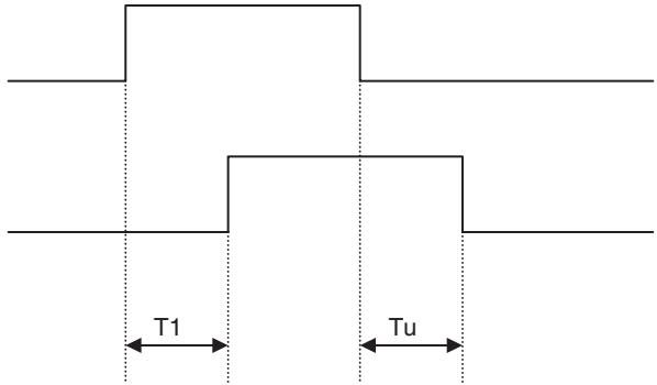
Note
The MC Unit supports processing of great amounts of data and varieties of peripheral devices to realize multi-axis applications. Due to the fact, it takes the MC Unit a certain period of time (8 seconds min.) to get ready for operation.
To make the MC Unit receive commands from the PLC without fail, the bit [Unit Ready] is provided. When sending commands from the PLC to the MC Unit, make sure to check the bit [Unit Ready].
For details of the bit [Unit Ready], see page 440.
7-4-1 Unit Control Bits
| Word | Variable | Bit | Name | I/O |
| n+0 | IW0300 | 00 | Unit Alarm Reset | Output |
Function
- If an error that requires stopping internal operation of the Unit occurs, it will be detected as an alarm.
- Using Unit Alarm Reset after having removed the cause of the error can clear the alarm.
Command and Operation
| Name | Specifications |
| Unit Alarm Reset | 0: Nil1: Does not turn ON the bit [Unit Alarm]↑: Clears the alarm occurring on Unit level↓: Nil |
The alarm on Unit level will be cleared when the bit [Unit Alarm Reset] is turned ON.
Status Condition
| Name | Specifications |
| Alarm Occurring | 0: No alarm occurring 1: Alarm occurring on MC Unit (linked to ERC indicator) |
| Unit Alarm Occurring | 0: No alarm occurring on Unit level 1: Alarm occurring on Unit level |
| Unit Alarm | 0: No Alarm occurring on Unit level or the bit [Unit Alarm Reset] is ON1: Alarm occurring on unit level |
| Unit Alarm Code | Output the code of the alarm occurring on Unit level |
- When an alarm occurs on the Unit level, the bits [Alarm Occurring], [Unit Alarm Occurring], and [Unit Alarm] turn ON and the alarm code will be stored in the Unit status data [Unit Alarm Code].
- If several alarms occur, only the code of the first alarm will be stored in [Unit Alarm Code].
Effect of Other Functions Nil
Effect on Other Functions When an alarm occurs, it affects other functions (operation failure, operation interruption, etc.)
System Parameter Nil
Program Example
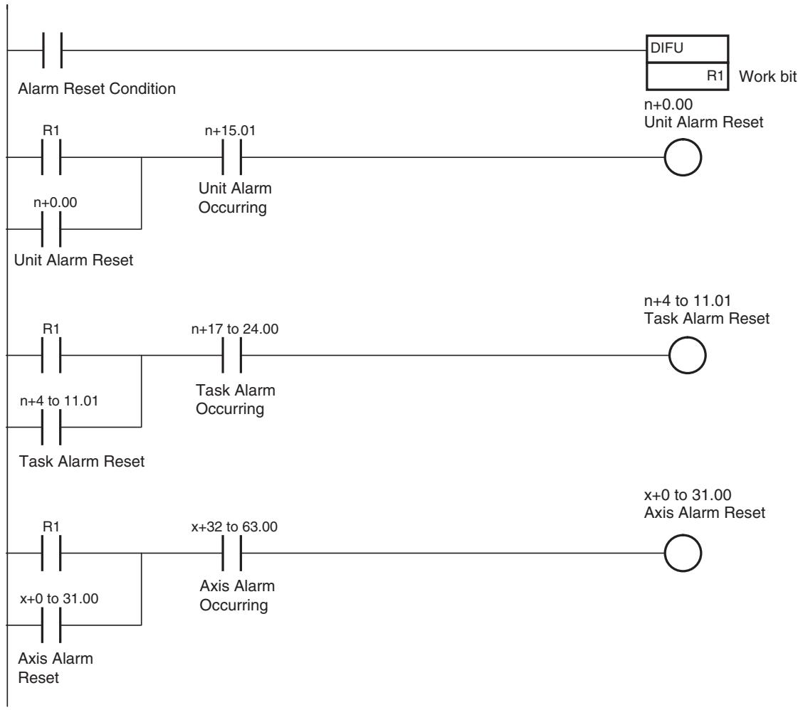
On MC Unit, there are three types of alarms:
- Unit alarm
- Task alarm
- Axis alarm
Alarms are reset on the basis of each type. Therefore, execute the alarm reset over the Unit, Task, and Axis to clear an alarm occurring on the MC Unit without fail.
Timing Chart
Basic operation (Alarm Occurring):
| Alarm Identification: Alarm Occurring | 1 0 |
| Alarm Identification: Unit Alarm Occurring | 1 0 |
| Unit Status Bit: Unit Alarm | 1 0 |
| Unit Status Data: Alarm Code | 0XXXX |
| Internal Alarm Status | 1 0 |
Basic operation (Alarm Reset):
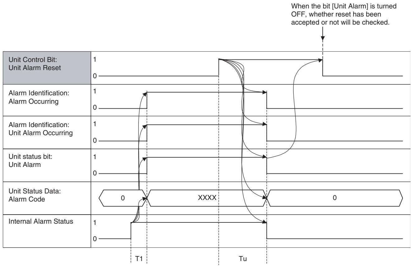
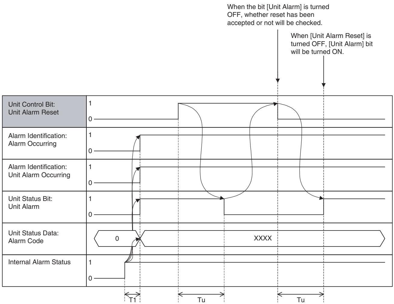
Alarm that cannot be reset occurs:
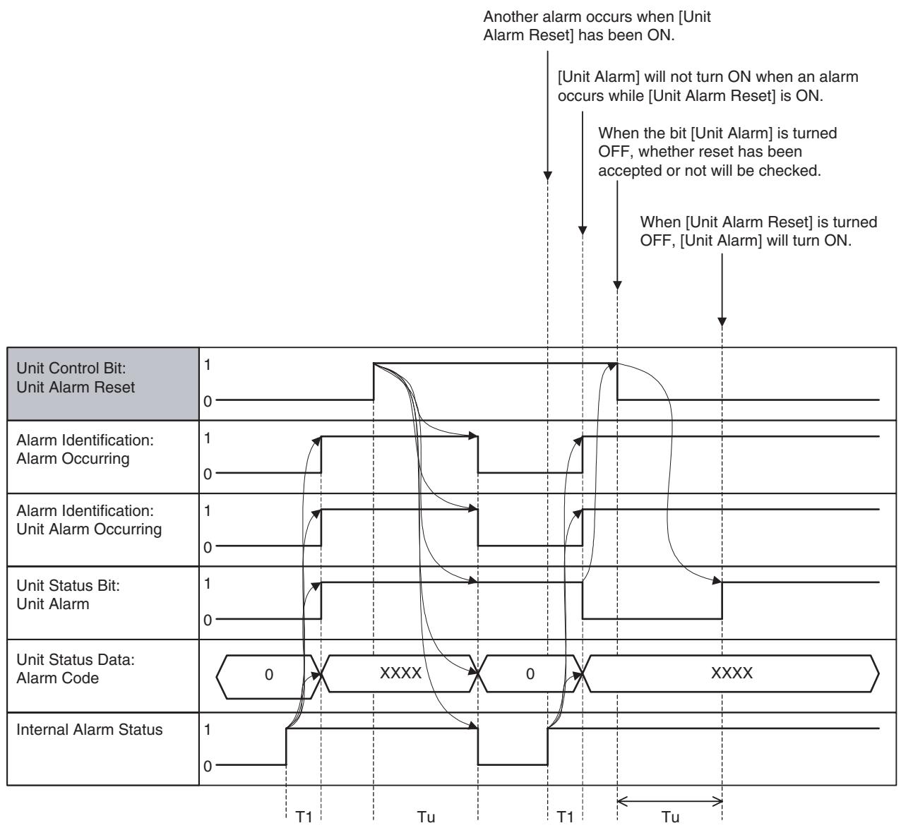
Alarm occurs when [Unit Alarm Reset] has been ON:
| Word | Variable | Bit | Name | I/O |
| n+0 | IW0300 | 01 | System Parameter Save | Output |
Function
With this function, system parameters that have been changed using IOWR instruction in the ladder program can be saved into the Flash ROM of the MC Unit.
Command and Operation
| Name | Specifications |
| System Parameter Save | 0: Nil1: Nil↑: Saves system parameters in the Flash ROM.↓: Nil |
- System parameters will be saved when the bit [System Parameter Save] is turned ON.
- Turning OFF the bit [System Parameter Save] after the command reception will not interrupt the processing.
Status Condition
| Name | Specifications |
| Flash Save Com-pleted | 0: Neither parameter nor position data save is completed 1: Parameter or position data save is completed (including error completion) |
- When saving is completed (normal completion or error completion), the bit [Flash Save Completed] will turn ON.
- The same status bit is used for saving position data. Therefore, it is not recommended to save system parameters simultaneously with position data.
Effect of Other Functions Nil
Effect on Other Functions Nil
System Parameter Nil
Program Example
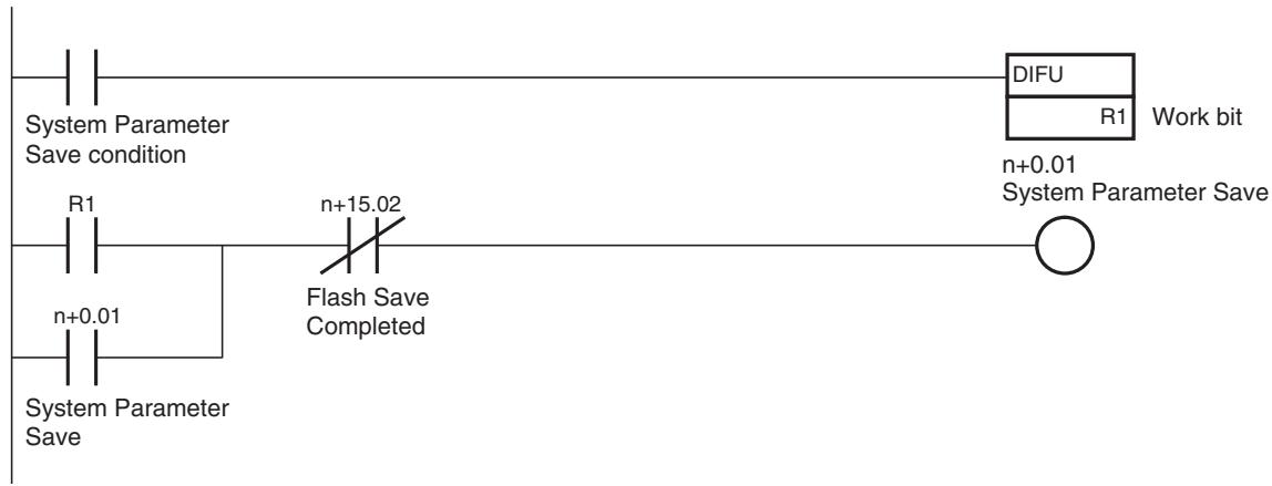
Timing Chart Basic operation:
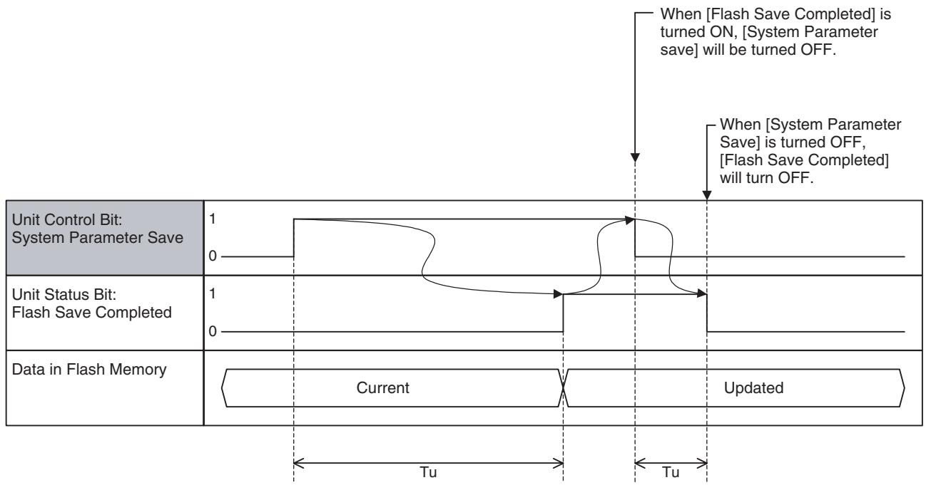
The timing chart will be the same as the above even at error completions. Use the bit [Unit Alarm] to confirm normal completion or error completion. (Confirm with the alarm as it seldom happens.)
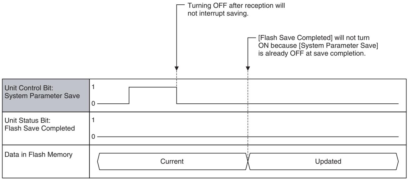
If [System Parameter Save] is turned OFF before completion:
| Word | Variable | Bit | Name | I/O |
| n+0 | IW0300 | 02 | Position Data Save | Output |
Function
With this function, the position data that has been changed using IOWR instruction or teaching function from ladder program is saved into the Flash ROM of the MC Unit.
Command and Operation
| Name | Specifications |
| Position Data Save | 0: Nil1: Nil↑: Saves position data in the Flash ROM↓: Nil |
- Position data will be saved when the bit [Position Data Save] is turned ON.
- Turning OFF the bit [Position Data Save] after the command reception will not interrupt the processing.
Status Condition
| Name | Specifications |
| Flash Save Com-pleted | 0: Neither parameter nor position data save is completed 1: Parameter or position data save is completed (including error completion) |
- When saving is completed (normal completion or error completion), the bit [Flash Save Completed] will turn ON.
- The same status bit is used for saving system parameters. Therefore, it is not recommended to save position data simultaneously with system parameters.
Effect of Other Functions Nil
Effect on Other Functions Nil
System Parameter
Nil
Program Example
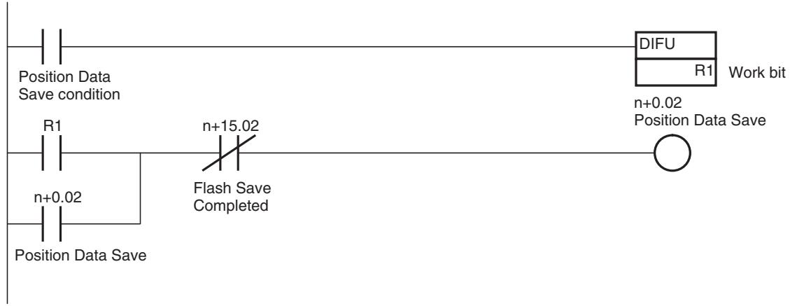
Timing Chart
Basic Operation:
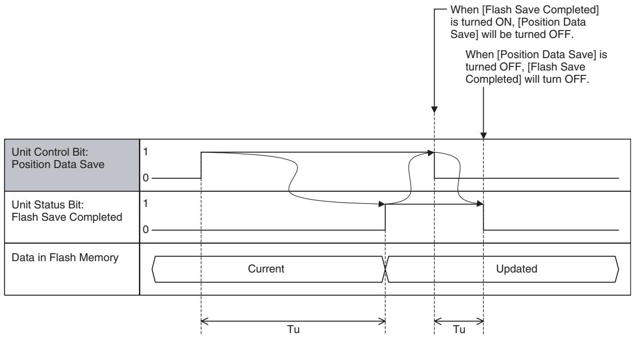
The timing chart will be the same as the above even at error completions. Use the bit [Unit Alarm] to confirm normal completion or error completion. (Confirm with the alarm as it seldom happens.)
| Words | Variables | Bits | Name | I/O |
| n+0 | IW0300 | 03 | Teaching Condition Setting | Output |
| n+0 | IW0300 | 04 | Teaching Type | Output |
| n+0 | IW0300 | 05 | Teaching Execution | Output |
| n+1 | IW0301 | 00-15 | Teaching Axis Setting 1-16 | Output |
| n+2 | IW0302 | 00-15 | Teaching Axis Setting 17-32 | Output |
Function
- To use the actual positions on an application in motion programs as position data, the present positions are stored in position data.
-
Generally, there are following 2 operations:
-
Teaching Condition Setting:
The axis and address of teaching object will be specified when the bit [Teaching Condition Setting] is turned ON. - Teaching Execution:
The present position will be stored in position data when the bit [Teaching Execution] is turned ON.
Command and Operation
| Name | Specifications |
| Teaching Condition Setting | 0: Nil1: Nil↑: Specifies the Teaching axis, reads the Teaching address.↓: Nil |
| Teaching Type | 0: Feedback present position1: Command present position↑: Nil↓: Nil |
| Teaching Execution | 0:Nil1:Nil↑: Writes present position specified with Teaching type into position data↓: Nil |
| Teaching Axis Setting 1-16 | 0: Nil1: Specifies the axis as a teaching axis↑: Nil↓: Nil |
| Teaching Axis Setting 17-32 | 0: Nil1: Specifies the axis as a teaching axis↑: Nil↓: Nil |
| Teaching Address | Specifies the teaching start address0-10239 |
- [Teaching Axis Setting 1-16], [Teaching Axis Setting 17-32], and [Teaching Address] will be read when the bit [Teaching Condition Setting] is turned ON, and then, teaching will be ready to be started.
- When the bit [Teaching Execution] is turned ON, the data specified with [Teaching Type] of the axes specified with the bits [Teaching Axis Setting 1-16] and [Teaching Axis Setting 17-32] will be stored in position data.
- The bit [Teaching Type] will be referenced when the bit [Teaching Execution] is turned ON and it cannot be changed during execution of teaching.
- If [Teaching Condition Setting] is omitted after teaching execution, the address of teaching object will be incremented for the number of axes specified with the bits [Teaching Axis Setting 1-16] and [Teaching Axis Setting 17-32].
-
Condition setting and execution can be performed simultaneously by turning ON the bits [Teaching Condition Setting] and [Teaching Execution] simultaneously. However, when an error occurred, there is no way to know which operation caused the error. Therefore, it is not recommended.
-
The bit [Teaching Address] will return to zero if the address after increment in teaching execution exceeds 10239 (27FFh).
Status Condition
| Name | Specifications |
| Teaching Warning | 0: Teaching condition setting, execution completed successfully 1: Condition error, Command disabled, No origin, or Address overflow |
| Teaching Condition Setting Completed | 0: When the bit [Teaching Condition Setting] is OFF 1: Teaching condition setting completed (including error completion) |
| Teaching Execution Completed | 0: When the bit [Teaching Execution] is OFF 1: Teaching execution completed (including error completion) |
| Teaching Address Monitor | Output the address of current teaching object |
- The bit [Teaching Warning] indicates the error status of teaching condition setting and teaching execution. It turns ON simultaneously with either of the bits [Teaching Condition Setting Completed] or [Teaching Execution Completed] under the following conditions respectively:
When Teaching condition setting is executed:
- When [Teaching Axis Setting 1-16] = [Teaching Axis Setting 17-32] = 0
- When there are any non-allocated axes among the axes specified with the bits [Teaching Axis Setting 1-16] and [Teaching Axis Setting 17-32]
- [Teaching Address] is outside of position data range
- When the addition of [Teaching Address] and the addresses for the number of axes specified with the bits [Teaching Axis Setting1-16] and [Teaching Axis Setting 17-32] exceeds the position data range
When Teaching is executed:
- When [Teaching Execution] was turned ON without teaching condition setting
- When the bits [Command Disabled/Enabled] for the axes specified with [Teaching Axis Setting 1-16] and [Teaching Axis Setting 17-32] are OFF, or when the bits [No Origin] for any of the axes are ON.
-
When the addition of [Teaching Address Monitor] and the addresses for the number of teaching-object axes exceeds the position data range
-
The bit [Teaching Condition Setting Completed] indicates the completion status (normal or error) of teaching condition setting and it will be turned OFF when the bit [Teaching Condition Setting] is turned OFF.
- The bit [Teaching Execution Completed] indicates the completion status (normal or error) of teaching execution and it will be turned OFF when the bit [Teaching Execution] is turned OFF.
- The bit [Teaching Address Monitor] indicates the address of the teaching object. It will be incremented for the number of axes specified with [Teaching Axis Setting 1-16] and [Teaching Axis Setting 17-32] when teaching execution is completed normally.
Effect of Other Functions
| Classification | Items | Effect |
| Physical status | Servo axis | No effect |
| Virtual axis | No effect | |
| I/O axis | No effect | |
| Counter axis | No effect | |
| Control status | In Position control | No effect |
| In Speed control | No effect | |
| In Torque control | No effect | |
| Status bits | Busy | No effect |
| In Servo Lock | No effect | |
| No Origin | Cannot execute Teaching if it is turned ON. | |
| Axis Operating | No effect | |
| Positioning Completed | No effect | |
| Positioning Completed (No.2) | No effect | |
| Axis Machine Lock Status | No effect | |
| Command Disabled/Enabled | Cannot execute Teaching if it is turned OFF. | |
| Axis Not Used/Used | No effect | |
| In Manual/Automatic Mode | No effect |
Effect on Other Functions Nil
System Parameter Nil
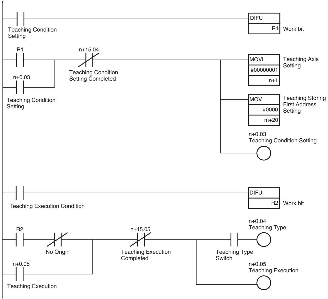
Program Example
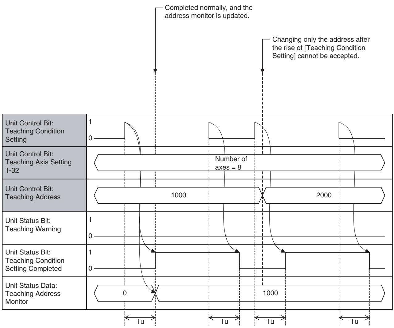
Timing Chart
Teaching Condition Setting (Normal completion):
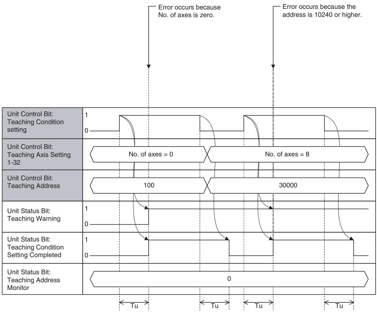
Teaching Condition Setting (Error Completion):
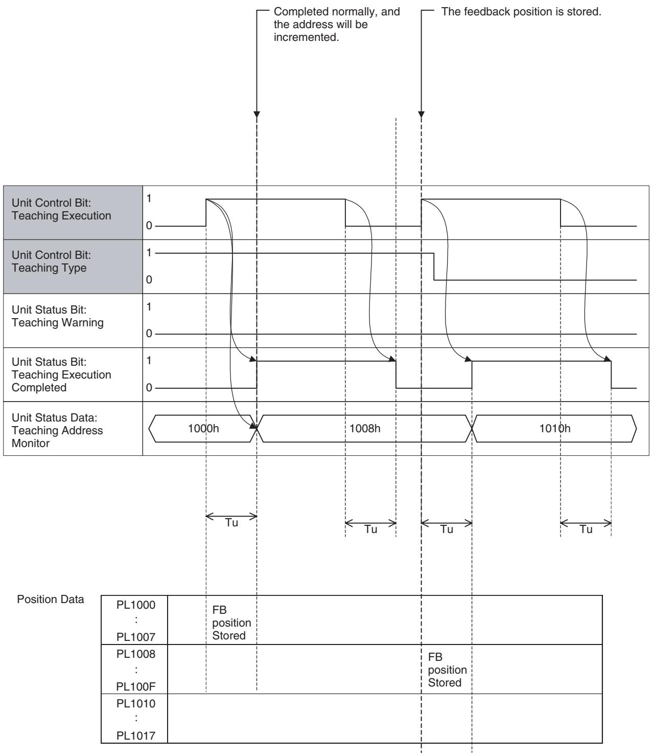
Teaching Execution (Normal completion):
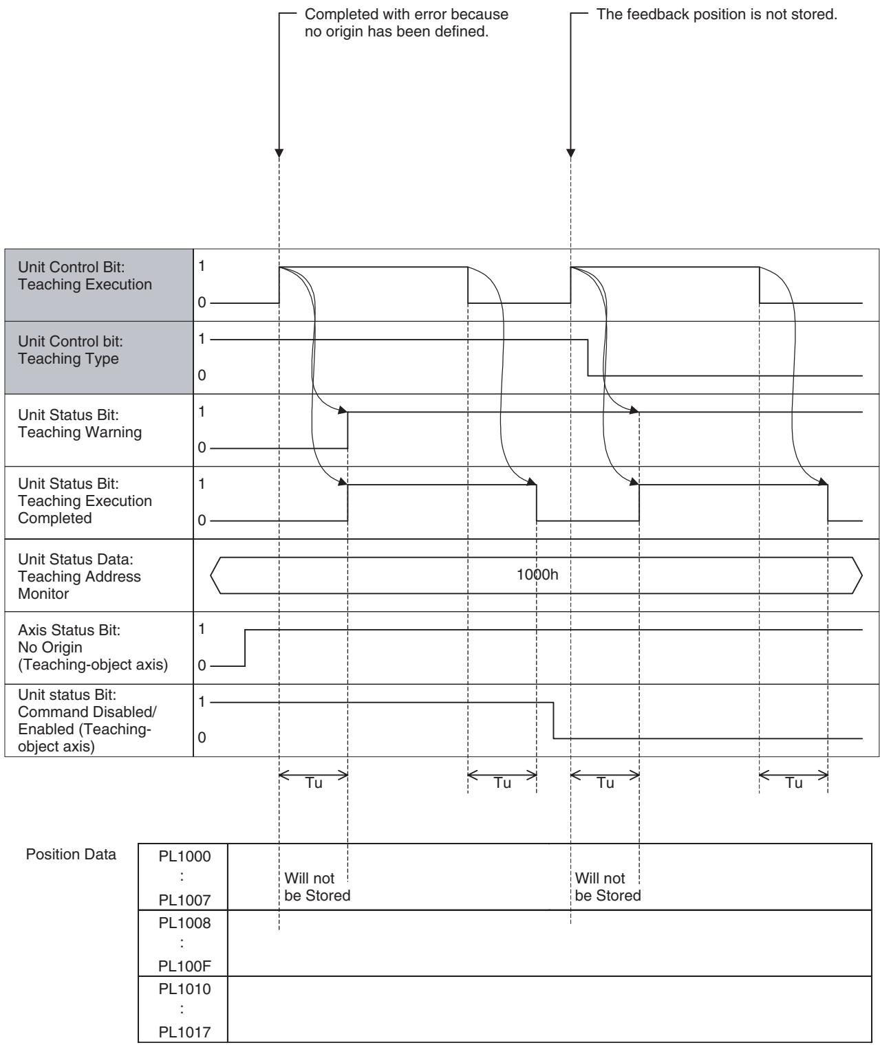
Teaching Execution (Error completion):
| Word | Variable | Bit | Name | I/O |
| n+0 | IW0300 | 06 | Servo Parameter Save | Output |
Function
With this function, the servo parameters that have been changed using IOWR instruction in the ladder program are saved into both the Flash ROM of the MC Unit and the EEPROM of the Servo.
Command and Operation
| Name | Specifications |
| Servo Parameter Save | 0: Nil1: Nil↑: Saves servo parameters in the Flash ROM and EEPROM.↓: Nil |
- Servo parameters will be saved when the bit [Servo Parameter Save] is turned ON.
- Turning OFF the bit [Servo Parameter Save] after the command reception will not interrupt the processing.
Status Condition
| Name | Specifications |
| Flash Save Com-pleted | 0: Neither parameter nor position data save is completed 1: Parameter or position data save is completed (including error completion) |
- When saving is completed (normal completion or error completion), the bit [Flash Save Completed] will turn ON.
- The same status bit is used for saving position data. Therefore, it is not recommended to save servo parameters simultaneously with position data.
Effect of Other Functions Nil Effect on Other Functions Nil System Parameter Nil
Program Example
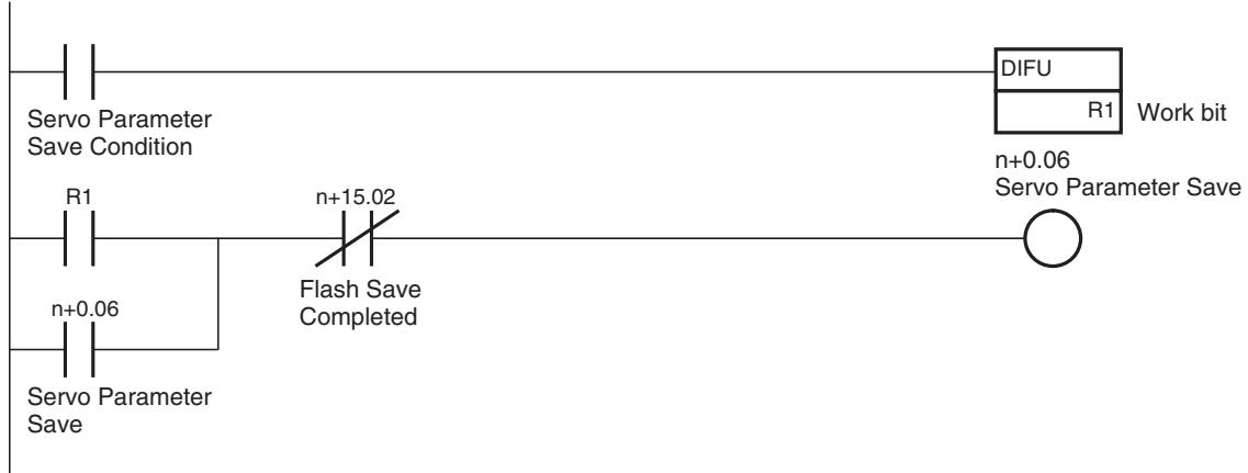
Timing Chart
Basic Operation:
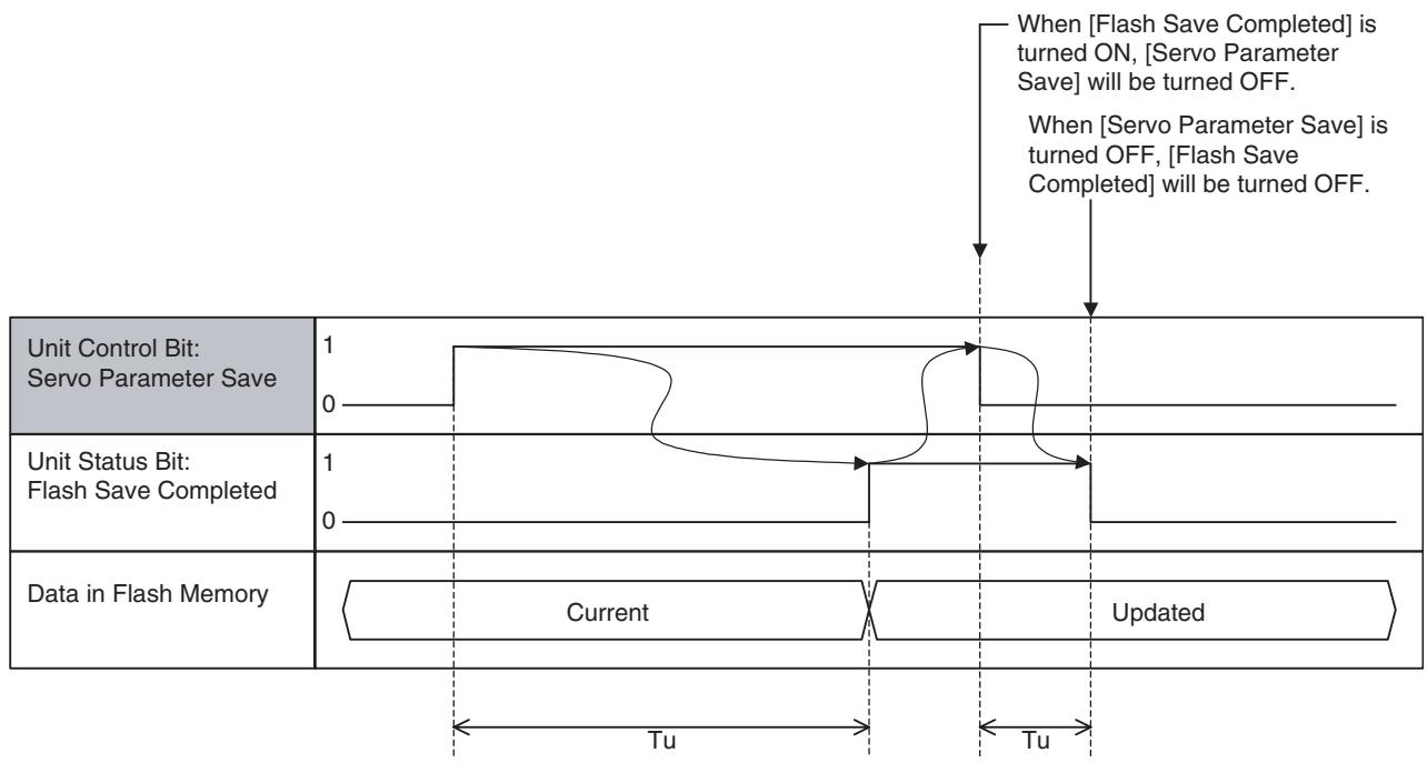
The timing chart will be the same as the above even at error completions. Use the bit [Unit Alarm] to confirm normal completion or error completion. (Confirm with the alarm as it seldom happens.)
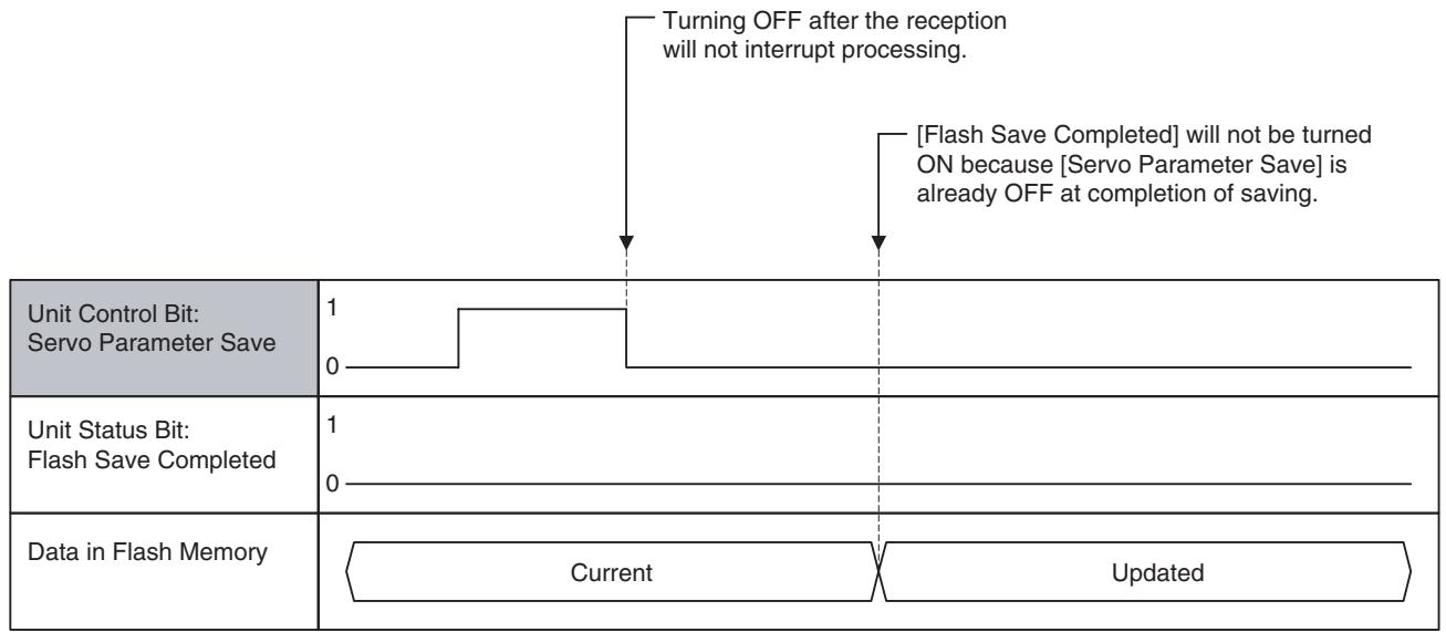
If [Servo Parameter Save] is turned OFF before completion:
| Word | Variable | Bit | Name | I/O |
| n+0 | IW0300 | 12-15 | Present Value Monitor Select | Output |
Function
- The present value of the operation data such as positions, speed, etc. unique to each axis is output as monitor data.
- Though data unique to each axis is handled, selection is made for the Unit. (Monitor data cannot be selected for each axis.)
Command and Operation
| Name | Function |
| Present Value Monior Select | Selects data to be output to present value monitor. |
| 0: Zero output Outputs 0. | |
| 1: Feedback position (coordinate system currently being selected) Outputs feedback position on the selected coordinate system. | |
| 2: Feedback position (machine coordinate system) Outputs feedback position on the machine coordinate system. | |
| 3: Command position (coordinate system currently being selected) Outputs command position on the selected coordinate system. | |
| 4: Command position (machine coordinate system) Outputs command position on the machine coordinate system. | |
| 5: Feedback speed 1 Outputs feedback speed (command unit/min) About the precision, refer to page 103. | |
| 6: Feedback speed 2 Outputs feedback speed (% or r/min). About the precision, refer to page 103. | |
| 7: Command speed 1 Outputs command speed (command unit/min). | |
| 8: Command speed 2 Outputs command speed (% or r/min). | |
| 9: Error Outputs error. | |
| 10: Torque Outputs Torque command value. | |
| 11 and above: Reserved for system Outputs 0. |
Status Condition
| Name | Function |
| Present Value Monitor Status | Indicates the output status of present value monitor. |
| 0: Zero output | |
| 1: Feedback position (coordinate system currently being selected) | |
| 2: Feedback position (machine coordinate system) | |
| 3: Command position (coordinate system currently being selected) | |
| 4: Command position (machine coordinate system) | |
| 5: Feedback speed 1 | |
| 6: Feedback speed 2 | |
| 7: Command speed 1 | |
| 8: Command speed 2 | |
| 9: Error | |
| 10: Torque | |
| 11 and above: Reserved for system. |
| Name | Function | ||
| Servo Axis | Virtual Axis | I/O axis, Counter axis | |
| Present Value Monitor | Selects from the following 11 to output | Always zero | |
| 0: ZeroValue range: 0, Unit: Nil | ← | ||
| 1: Feedback position (selected coordinate system)Value range: -2147483648 to 2147483647,Unit: Command unit | Same value as for 3 | ||
| 2: Feedback position (machine coordinate system)Value range: -2147483648 to 2147483647,Unit: Command unit | Same value as for 4. | ||
| 3: Command position (selected coordinate system)Value range: -2147483648 to 2147483647,Unit: Command unit | ← | ||
| 4: Command position (machine coordinate system)Value range: -2147483648 to 2147483647,Unit: Command unit | ← | ||
| 5: Feedback speed 1Value range: -, Unit: Command unit/min | Same value as for 7. | ||
| 6: Feedback speed 2Value range: -,Unit: 0.01% (motor rated speed) or 0.01 r/min | Same value as for 8. | ||
| 7: Command speed 1Value range: -, Unit: Command unit/min | ← | ||
| 8: Command speed 2Value range: -,Unit: 0.01% (motor rated speed) or 0.01 r/min | Always zero | ||
| 9: ErrorValue range: -, Unit: pulse | Always zero | ||
| 10: TorqueValue range: -,Unit: 0.01% (In Position/Speed control: motor rated torque)0.01%(In Torque control: motor maximum torque) | Always zero | ||
- Output status of [Present Value Monitor] is reflected in the bit [Present Value Monitor Status].
- The operation data such as axis position and speed is output to [Present Value Monitor].
- When [Present Value Monitor Select] is set to "0" or "11" and above, 0 will be output to [Present Value Monitor Status] and [Present Value Monitor].
- When the unit status bit [Command Disabled/Enabled] is OFF, 0 will be output to [Present Value Monitor].
Effect of Other Functions
| Classification | Item | Effects |
| Physical Status | Servo axis | Refer to the table [Present value monitor] above. |
| Virtual axis | Refer to the table [Present value monitor] above. | |
| I/O axis | Refer to the table [Present value monitor] above. | |
| Counter axis | Refer to the table [Present value monitor] above. | |
| Control Status | In Position control | No effect |
| In Speed control | No effect | |
| In Torque control | No effect | |
| Status Bits | Busy | No effect |
| In Servo Lock | No effect | |
| No Origin | No effect | |
| Axis Operating | No effect | |
| Positioning Completed | No effect | |
| Positioning Completed (No.2) | No effect | |
| Axis Machine Lock Status | No effect | |
| Command Disabled/Enabled | When OFF: [Present Value Monitor] = 0 When ON: No effect | |
| Axis Not Used/Used | No effect | |
| In Manual/Automatic Mode | No effect |
Effect on Other Functions Nil
System Parameter
| No. | Name | Purpose |
| P00004 | Unit Function Select | Determining the unit for the feedback speed 2 |
Program Example

Timing Chart Basic operation:
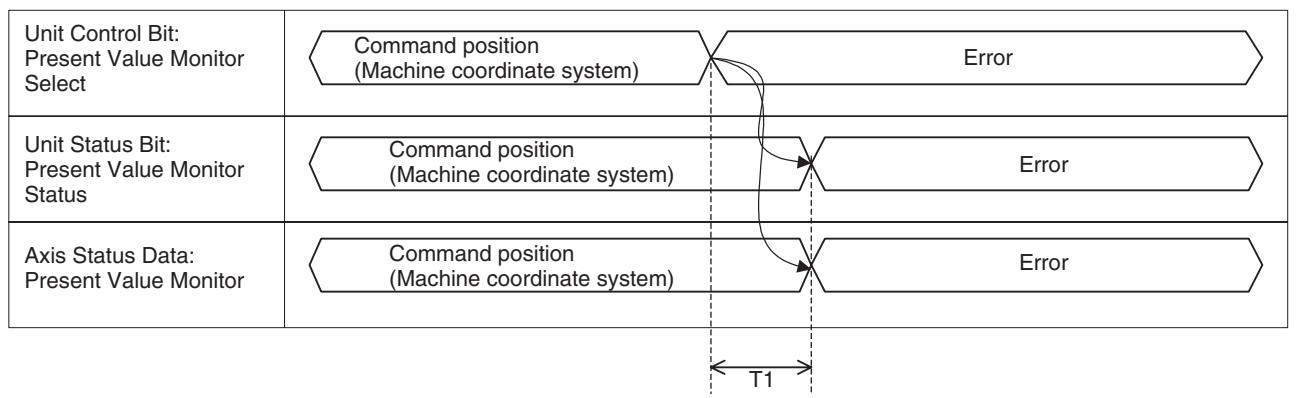
7-4-2 Unit Status Bits
| Word | Variable | Bit | Name | I/O |
| n+15 | OW0303 | 00 | Unit Ready | Input |
Function
This bit indicates the status of operation preparation in the Unit.
Status Condition
| Words | bit | Name | Specifications |
| n+15 | 00 | Unit Ready | 0: The Unit is not ready to accept commands.1: The Unit is ready to accept commands. |
| Effect on Other Functions | ·The bit [Unit Ready] will be turned ON after the power is turned ON, the initial processing is completed, and the motion task becomes ready to receive commands. ·During normal operations, the bit [Unit Ready] will be turned OFF when an alarm that requires the system stop occurs. |
| ·When the bit [Unit Ready] is OFF, all the commands from the cyclic area will be ignored. ·Whether the motion program can be actually executed or not depends on the bit [Command Disabled/Enabled] of the axis declared by PROG command. |
System Parameters Nil
Program Example The MC Unit supports processing of great amounts of data and varieties of peripheral devices to realize multi-axis applications. Due to the fact, it takes the MC Unit a certain period of time (8 seconds min.) to get ready for operation.
Additionally, the MC Unit and CPU Unit establish communications asynchronously. To make the MC Unit receive instructions from PLC without fail, make sure to send instructions from the CPU Unit to the MC Unit when the bit [Unit Ready] is ON.
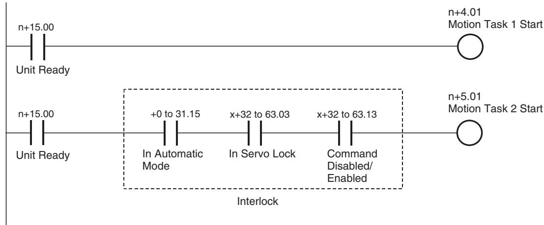
Note Programs (for arithmetic operation, etc.) that do not use axes may start motion tasks with the bit [Unit Ready], however, programs that use axes require interlock for the used axes as shown above.
Timing Chart Nil
| Word | Variable | Bit | Name | I/O |
| n+15 | OW0303 | 07 | External Forced Stop Request | Input |
| 08 | External Forced Stop Status | Input |
Function
The bit [External Forced Stop Request] indicates the occurrence of a forced stop request from something other than the input variable. The bit [External Forced Stop Status] indicates the status of the stop caused by a forced stop request.
Status Condition
| Name | Specifications |
| External Forced Stop Request | 0: No forced stop request from something (FINS, etc.) other than input variable 1: There is a forced stop request from something (FINS, etc.) other than input variable. |
| External Forced Stop Status | 0: No forced stop request, or processing for the stop 1: Stopped with a forced stop request |
The bit [External Forced Stop Request] is turned ON on the timing starting the stop for all the slaves after receiving [Task Control Setting (axis, task stop)] successfully while it will be turned OFF when it receives [Task Control Setting (axis, task stop cancel)] successfully.
The bit [External Forced Stop Request] will be turned ON when the operating mode of the CPU Unit is switched to Program Mode. After confirming that all the axes and tasks have been stopped, the bit [External Forced Stop Request] will be turned OFF.
The bit [External Forced Stop Status] will be turned ON when processing for each stopping operation is completed after the rise of the bit [External Forced Stop Request].
Details of the above status are stored in the system variables shown below:
| Address | Name | Description |
| SW0004 | Forced stop request from tool: Details of the request | Indicates the forced stop request from tool Bit00: Axis, task stop Bit01: Axis, task stop cancel Bit06: CAM data buffer copy Bit07: Program buffer copy |
| SW0005 | Forced stop request from tool: Object 1 | Indicates the forced stop request from tool Bit00-07: 0: There is no forced stop request for Motion task 1-8 1: There is a forced stop request for Motion task 1-8 Bit08: 0/1 Reserved |
| SW0006 | Forced stop request from tool: Object 2 | Indicates the forced stop request from tool Bit00-31: 0: There is no forced stop request for Axis 1-32 1: There is a forced stop request for Axis 1-32 |
| SW0007 | ||
| SW0008 | Reserved | Reserved |
| SW0009 | Forced stop status from tool: Object 1 | Indicates the forced stop status from tool Bit00-07: 0: Motion task 1-8 being executed 1: Motion task 1-8 being stopped Bit08: 0/1 Reserved |
| SW000A | Forced stop status from tool: Object 2 | Indicates the forced stop status from tool Bit00-31: 0: Axis 1-32 being operated 1: Axis 1-32 being stopped |
| SW000B |
Effect on Other Functions
While the bit [External Forced Stop Request] is ON, all the commands except for FINS commands are ignored.
System Parameter
Nil
Timing Chart
Nil
7-4-3 Motion Task Control Bits
| Words | Variables | Bits | Name | I/O |
| n+4 | IW0340 | 01 | Motion Program Start (Task 1) | Output |
| - | - | |||
| n+11 | IW0347 | Motion Program Start (Task 8) | ||
| 02-03 | Start Mode (Task 1) | |||
| - | ||||
| Start Mode (Task 8) |
Function
- Specifying a program number and starting the motion task can execute the motion program that was stored in the MC Unit.
Command and Operation
| Name | Specifications |
| Motion Program Start | 0: Nil1: Nil↑: Starts the motion program operation following the specified Start Mode.↓: Nil |
| Start Mode | 0,3: Reads program number and executes the program from top.1: Executes the program from the block indicated by Executing Motion Block Number. Operation at resuming interrupted programs varies depending on the command used or stopping status.2: Executes the program from the next block of the block indicated by Executing Motion Block Number. |
| Motion Program Number | Specifies program number to be executed in motion task.0-499 |
- Motion program execution can be started or resumed by turning ON the bit [Motion Program Start].
- Turning ON the bit [Motion Program Start] when a motion program is being executed is ignored.
- If there is an interrupted program ([Executing Motion Block Number] is not 0), the bit [Start Mode] will be referenced to determine the operation at resuming when the bit [Motion Program Start] is turned ON.
- If there is no interrupted program ([Executing Motion Program Number] is 0), the bit [Start Mode] does not have any function, i.e. a program number is read to start the program from the begging.
- After a program was interrupted, if one of the following conditions is met, the bit [Start Mode] will be disabled, i.e. a program number is read to start the program from the beginning:
The program number has been changed.
he program has been changed, deleted, or transferred.
The CAM data has been changed, deleted, or transferred.
(Note that all the programs and CAM data other than the ones being executed are also the objects.)
-
If the bit [Start Mode] is 0 or equivalent to 0, [Motion Program Number] will be referenced when [Motion Program Start] is turned ON.
-
In [Start Mode] = 1, the operation at resuming an interrupted program varies depending on the command being executed as shown below:
| Command | Operation |
| MOVE/MOVEL/MOVEC/MOVEI/MOVET | See 7-2-3 Automatic Mode (page 386). |
| MOVETRAV/MOVELINK/CAMBOX (1 cycle) | When interrupted midway of a block, resumes to finish the remaining travel distance. When interrupted at the end of a block, the entire program will be executed from the beginning again. |
| DATUM/CAM | The entire program is executed again from the beginning regardless of whether it was interrupted midway or at the end. |
Status Condition
| Name | Specifications |
| Start Bit (supported in Unit Ver. 3.0 or later) | 0: Motion Program Operating Bit OFF (0) 1: Motion Program Operating Bit ON (1) |
| Motion Program Operating | 0: Motion task is not executing program operation. 1: Motion task is executing program operation (turned OFF after deceleration or block stop completion). |
| Motion Program Operation Completed | 0: When program operation is started 1: END command was executed |
| Executing Motion Program Number | Outputs the program number of the program currently being executed with motion task or temporarily being stopped. |
| Executing Motion Block Number (Single execution command) | • Outputs the block number of the single execution command currently being executed with motion task, or temporarily being stopped. • During execution of parallel branching, the block number of the leftmost block is output. |
| Executing Motion Block Number (Multiple execution command) | • Outputs the block number of the multiple execution command currently being executed with motion task, or temporarily being stopped. • During execution of parallel branching, the block number of the leftmost block is output. |
- The bit [Start] returns the ON/OFF status of the bit [Motion Program Operating] from the CPU Unit as is.
When a program with a short execution time is executed, detection by the ladder program of whether the bit [Motion Program Operation Completed] at the end of the program has turned ON may not be possible. In this situation, perform the following processing in the ladder program to detect whether the program has completed.
Bit [Start] is ON and bit [Motion Program Operation Completed] is ON.
- The bit [Motion Program Operating] indicates the execution status of the motion program. It will be turned ON during program execution, and OFF when deceleration stop or block stop is completed, or when the operation is completed with END command execution.
- The bit [Motion Program Operation Completed] indicates the status of whether the program has been executed to the end or not. It will be turned ON when the operation is completed with END command execution, and it will be turned OFF when the next program operation is started.
-
[Executing Program Number] indicates the program number of the program being executed. It will be updated when a new program execution is started. If program operation is interrupted or completed, the value immediately before will be held.
-
[Executing Motion Block Number (Single execution command)] indicates the block number of the single execution command currently being executed. It will be updated only when a command execution is started. If program operation is interrupted or completed, the value immediately before will be held, and updated when execution of the next block is started in Pass Mode section.
Note
1-shot output may occur. In that case, depending on the Scan Time of the ladder program and the Unit Scan Time of the MC Unit, the output may not be reflected in the ladder program.
- [Executing Motion Block Number (Multiple execution command)] indicates the block number of the multiple execution command currently being executed. It will be updated only when a command execution is started. If program operation is interrupted or completed, the value immediately before will be held.
Note
When several multiple execution commands are executed in one Unit Scan, regardless of the Scan Time of the ladder program or the Unit Scan Time of the MC Unit, complete execution status cannot be reflected in the ladder program.
Effect of Other Functions
- When the bits [Deceleration Stop] and [Block Stop] are turned ON, motion program execution cannot be started by turning ON the bit [Motion Program Start].
- The axes declared with PROG command of the program to be executed are influenced as shown below. When they could not be started, the bit [Start Warning] is turned ON.
| Classification | Items | Effect |
| Physical Status | Servo axis | No effect |
| Virtual axis | No effect | |
| I/O axis | If declared, the alarm [201Ah: Axis declaration error] will occur. | |
| Counter axis | If declared, the alarm [201Ah: Axis declaration error] will occur. | |
| Status Bits | Busy | No effect |
| In Servo Lock | No effect | |
| No Origin | No effect | |
| Axis Operating | No effect | |
| Positioning Completed | No effect | |
| Positioning Completed (No.2) | No effect | |
| Axis Machine Lock Status | No effect | |
| Command Disabled/Enabled | Cannot be executed when OFF | |
| Axis Not Used/Used | Cannot be executed when ON | |
| In Manual/Automatic Mode | Cannot be executed when OFF |
Effect on Other Function
Nil
System Parameter
Nil
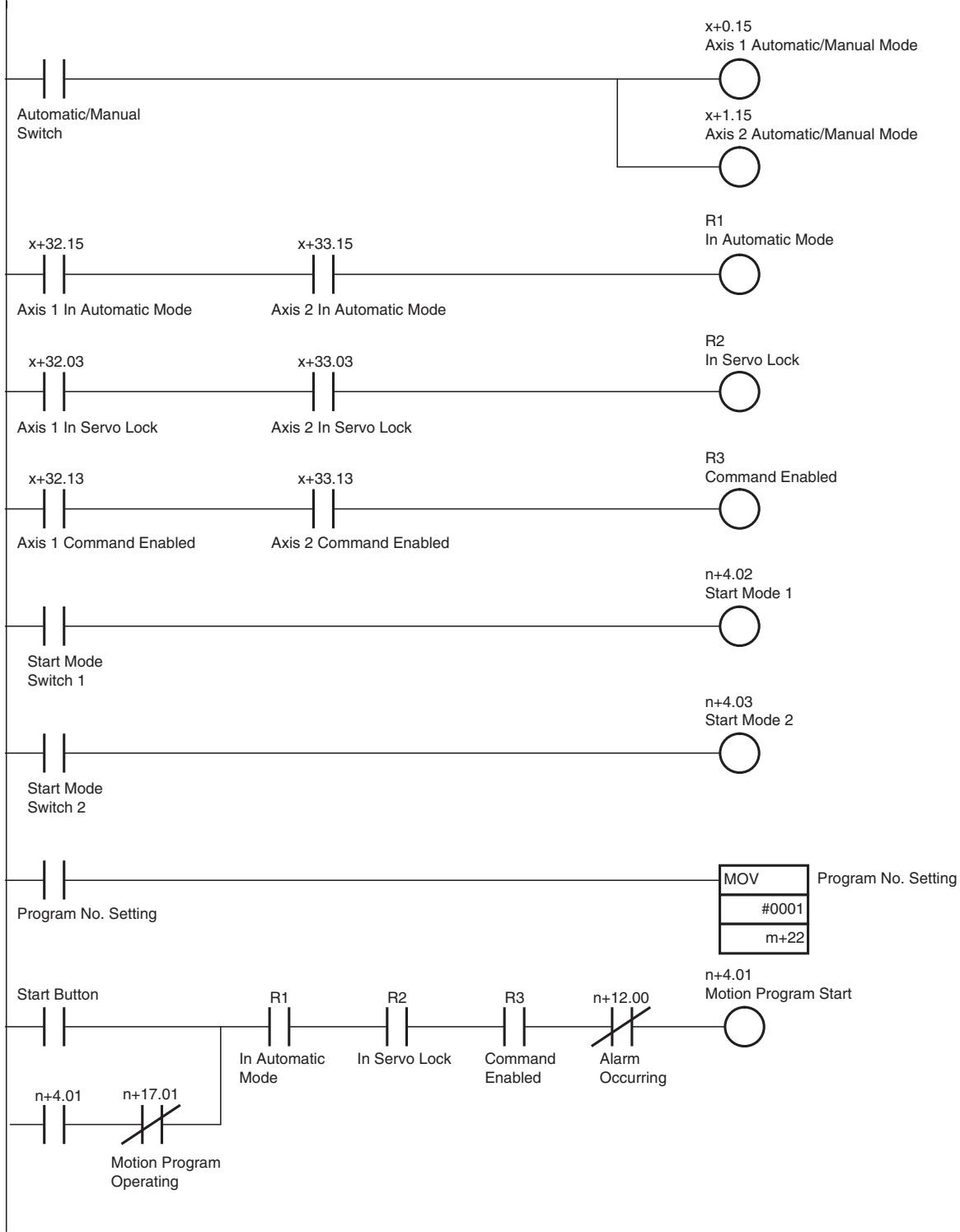
Program Example
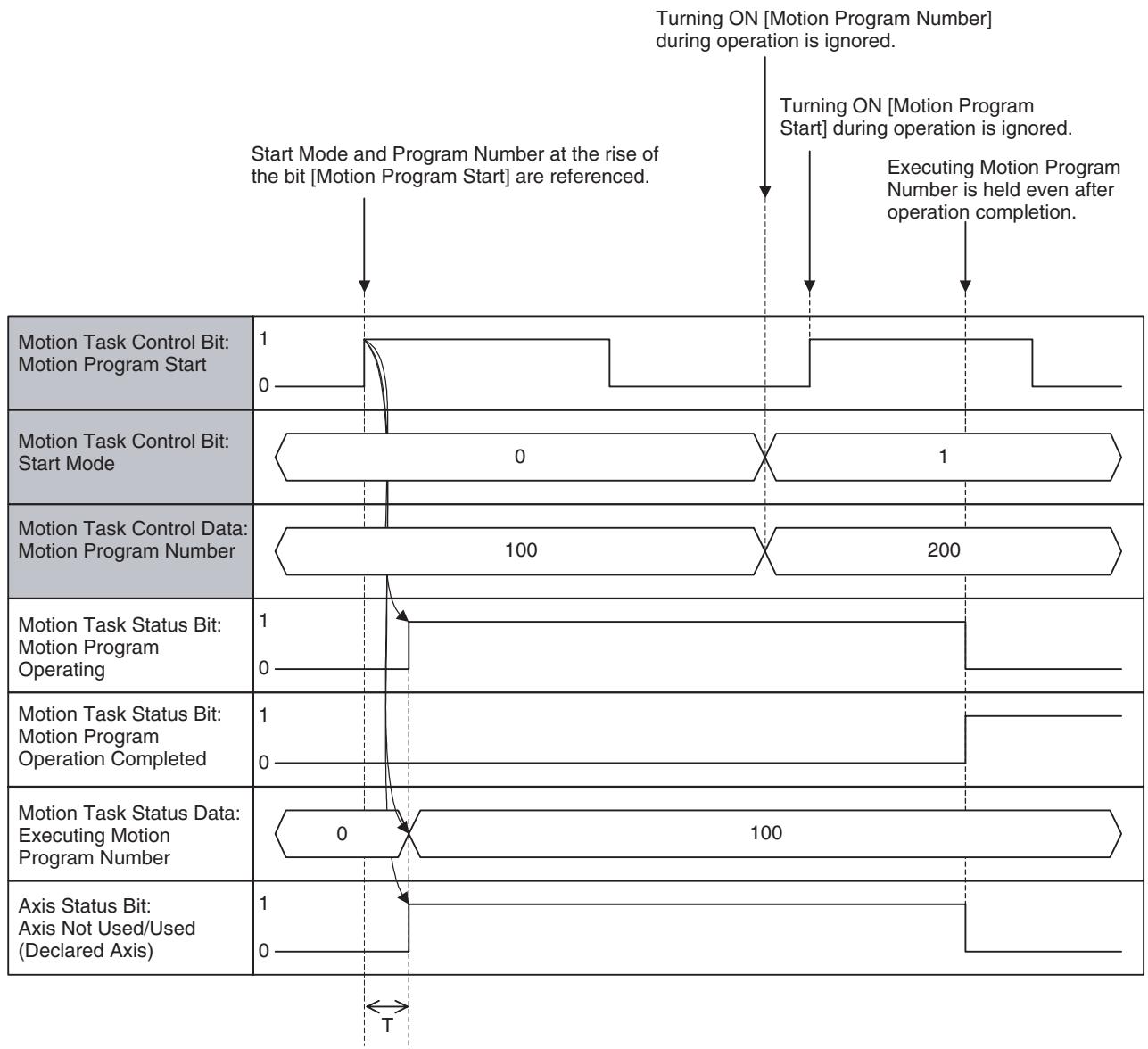
Timing Chart
Transition of Executing Motion Block Number:
| Programs to be executed | |
| Row No. | |
| 1 | PROG P100 Q00000003; |
| 2 | ABL MOVE [J01]1000 [J02]1000; |
| 3 | #MW1000 = 1000; |
| 4 | #MW1000 = 2000; |
| 5 | #MW1000 = 3000; |
| 6 | ABLMOVE [J01]#MW1000 [J02]#MW1000; |
| 7 | END; |
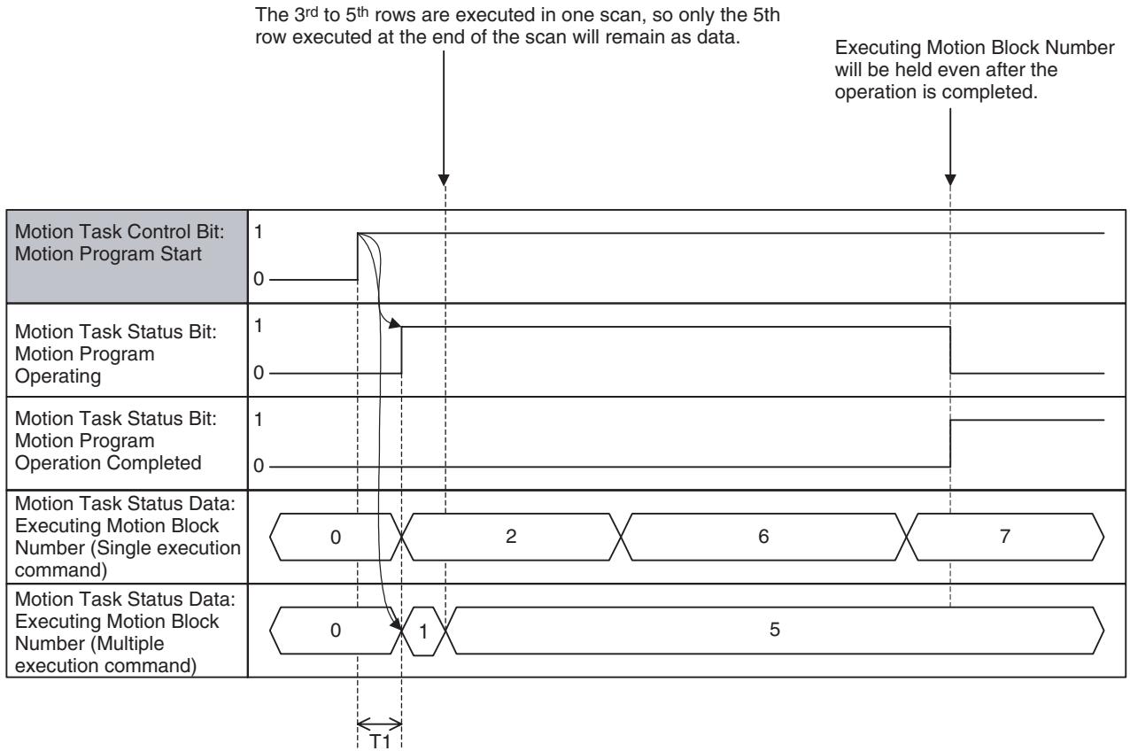
Note This is the case where 4 commands can be executed simultaneously in 1 scan.
| Word | Variable | Bit | Name | I/O |
| n+4 | IW0340 | 04 | Deceleration Stop (Task 1) | Output |
| - | - | - | ||
| n+11 | IW0347 | Deceleration Stop (Task 8) |
Function
Turn On the bit [Deceleration Stop] to stop the motion program being executed regardless of end of blocks.
Command and Operation
| Name | Specifications |
| Motion Program Start | 0: Nil1: Nil↑: Starts the motion program following the specified Start Mode.↓: No |
| Start Mode | 0,3: Reads program number and executes the program from top.1: Executes the program from the block indicated by Executing Motion Block Number. Operation at resuming the interrupted program varies depending on the command used or stopping status.2: Executes the program continuously from the next block of the block indicated by Executing Motion Block Number. |
| Deceleration Stop | 0: No1: Prohibits motion program start.↑: Executes deceleration stop regardless of the blocks.↓: No |
- The motion program currently being executed will be stopped with deceleration regardless of the ends of blocks when the bit [Deceleration Stop] is turned ON.
- The motion program execution cannot be started when the bit [Deceleration Stop] is ON.
- Turning OFF the bit [Deceleration Stop] after turning it ON once will not interrupt the deceleration.
-
Following operations will occur for commands without movement:
-
Single execution commands other than Axis movement, Axis operation start, and Axis operation end: The operation will not be interrupted and stop at the end of the block.
- Multiple execution commands:
The operation will stop at the end of the block without waiting for deceleration stop of movement command.
- If the bit [Deceleration Stop] is turned ON after axis operation start command has been executed, operations shown in the table below will occur.
| Command | Operation |
| MOVELINK: Link Operation | Before synchronization condition is satisfied: Cancels standing by for synchronization and stops. After synchronization condition is satisfied: Cancels synchronization and executes deceleration stop. |
| CAMBOX: Electronic Cam, Syn-chronous | Before synchronization condition is satisfied: Cancels standing by for synchronization and stops. After synchronization condition is satisfied: Cancels synchronization and executes deceleration stop. |
| CONNECT: Electronic Shaft | Cancels synchronization and executes deceleration stop. |
| SYNC: Trailing Synchronization | Before synchronization condition is satisfied: Cancels standing by for synchronization and stops. After synchronization condition is satisfied: Cancels synchronization and executes deceleration stop. |
| ADDAX: Travel Distance Superimpose | Cancels synchronization and executes deceleration stop. |
| SPEED: Speed Control | Decelerates to zero speed, and switches to Position Control Mode. After position loop is formed, the operation will be stopped. |
| TORQUE: Torque Control | Reduce torque to zero, and switches to Position Control Mode. After position loop is formed, the operation will be stopped. |
The resuming operation is determined by [Start Mode]. For details, see Start Mode on page 443.
Status Condition
| Name | Specifications |
| Motion Program Operating | 0: Motion task is not executing program operation. 1: Motion task is executing program operation (turned OFF after deceleration or block stop is completed). |
| Motion program Operation Com-pleted | 0: When starting program operation 1: END command was executed. |
| Motion Program Number | Specifies the program number to be executed in motion task. 0-499 |
| Executing Motion Program Number | Outputs the program number of the program currently being executed in motion task or temporarily being stopped. |
| Executing Motion Block Number (Sin-gle execution com-mand) | • Outputs the block number of the single execution command currently being executed with motion task, or temporarily being stopped. • During execution of parallel branching, the block number of the leftmost block is output. |
| Executing Motion Block Number (Multi-ple execution com-mand) | • Outputs the block number of the multiple execution com-mand currently being executed with motion task, or tempo-rarily being stopped. • During execution of parallel branching, the block number of the leftmost block is output. |
For details, see Motion Program Start and Start Mode on page 443.
Effect of Other Functions
Nil
Effect on Other Functions
When the bit [Deceleration Stop] is turned ON, turning ON the bit [Motion Program Start] will not start the motion program execution.
System Parameter
Nil
Program Example
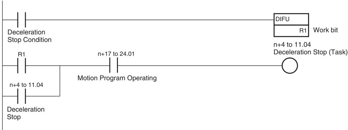
Timing Chart
| Programs to be executed | |
| Row No. | |
| 1 | PROG P100 Q00000003; |
| 2 | ABL MOVEL [J01]1000 [J02]1000; |
| 3 | #MW1000 = 1000; |
| 4 | #MW1000 = 2000; |
| 5 | #MW1000 = 3000; |
| 6 | ABL MOVEL [J01]#MW1000 [J02]#MW1000; |
| 7 | END; |
The bit [Deceleration Stop] is turned ON during execution of this block.
After deceleration stop is completed,
Executing Motion Program Number and
Executing Motion Block Number will be held.
The bit [Motion Program Operation
Completed] is turned ON because END
command has not been executed.
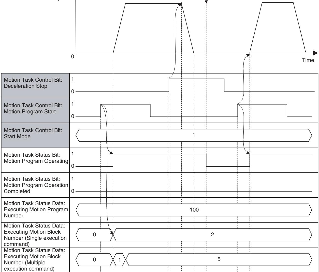

Stop in Pass Mode:
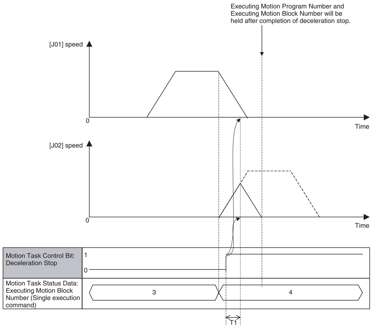
| Program to be executed | |
| Row No. | |
| 1 | PROG P100 Q00000003; |
| 2 | SPEED [J01]1000 T 100; |
| 3 | MOVEL [J02]1000; |
| 4 | END; |
The bit [Deceleration Stop] is turned ON after having started execution of this block.
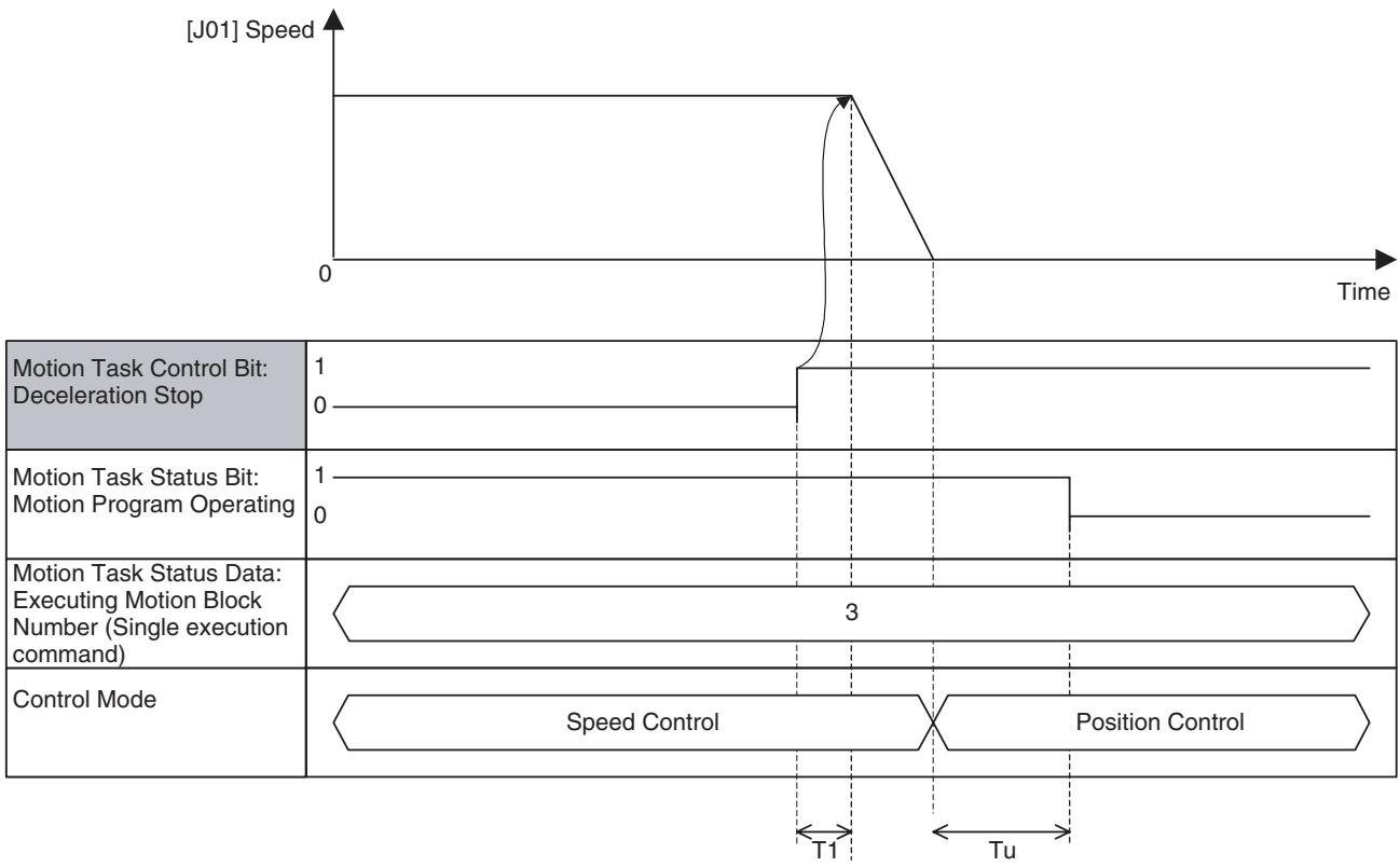
Stop in Speed or Torque Control:
| Word | Variable | Bit | Name | I/O |
| n+4 | IW0340 | 05 | Block Stop (Task 1) | Output |
| - | - | - | ||
| n+11 | IW0347 | Block Stop (Task 8) |
Function
With this function, the motion program is stopped at the end of the block currently being executed.
Command and Operation
| Name | Specifications |
| Motion Program Start | 0: Nil1: Nil↑: Starts motion program operation following the specified Start Mode.↓: No |
| Start Mode | 0,3: Reads program number and executes the program from top.1:Executes the program from the block indicated by Executing Motion Block Number. Operation at resuming interrupted programs varies depending on the command used or stopping status.2:Executes the program from the next block of the block indicated by Executing Motion Block Number. |
| Block Stop | 0:Nil1:Prohibits motion program start.↑:Executes deceleration stop at the end of the block currently being executed.↓:Nil |
- The motion program currently being executed is stopped at the end of the block by turning ON the bit [Block Stop].
- Motion program execution cannot be started while the bit [Block Stop] is ON.
- Turning OFF the bit [Deceleration Stop] after it has been turned ON will not interrupt the block stop operation.
- When the bit [Block Stop] is turned ON after an axis operation start command has been executed, operations described in the table below will occur:
| Command | Operation |
| MOVELINK: Link Operation | Before synchronization condition is satisfied: Cancels standing by for synchronization and stops. After synchronization condition is satisfied: Cancels synchronization and executes deceleration stop. |
| CAMBOX: Electronic Cam, Synchroeous | Before synchronization condition is satisfied: Cancels standing by for synchronization and stops. After synchronization condition is satisfied: Cancels synchronization and executes deceleration stop. |
| CONNECT: Electronic Shaft | Cancels synchronization and executes deceleration stop. |
| SYNC: Trailing Synchronization | Before synchronization condition is satisfied: Cancels standing by for synchronization and stops. After synchronization condition is satisfied: Cancels synchronization and executes deceleration stop. |
| ADDAX: Travel Distance Superimpose | Cancels synchronization and executes deceleration stop. |
| SPEED: Speed Control | Decelerates to zero speed, and switches to Position Control Mode. After position loop is formed, the operation will be stopped. |
| TORQUE: Torque Control | Reduce torque to zero, and switches to Position Control Mode. After position loop is formed, the operation will be stopped. |
Status Condition
| Name | Specifications |
| Motion Program Operating | 0: Motion task is not executing program operation. 1: Motion task is executing program operation (turned OFF after completion of deceleration or block stop) |
| Motion Program Operation Completed | 0: When starting program operation 1: END command was executed. |
| In Block Stop | 0: Not in Block Stop 1: In Block Stop |
| Motion Program Number | Specifies program number to be executed in motion task. 0-499 |
| Executing Motion Program Number | Outputs the program number of the program currently being executed in motion task or temporarily being stopped. |
| Executing Motion Block Number (Single execution command) | • Outputs the block number of the single execution command currently being executed with motion task, or temporarily being stopped. • During execution of parallel branching, the block number of the leftmost block is output. |
| Executing Motion Block Number (Multiple execution command) | • Outputs the block number of the multiple execution command currently being executed with motion task, or temporarily being stopped. • During execution of parallel branching, the block number of the leftmost block is output. |
For details, see Motion Program Start and Start Mode on page 443.
Effect of Other Functions
Block Stop is executed even for blocks with [NSTOP command: Single block ignored] specification (stopping is prioritized).
Effect on Other Functions
Turning ON the bit [Motion Program Start] will not start motion program execution while the bit [Block Stop] is turned ON.
System Parameter
Nil
Program Example
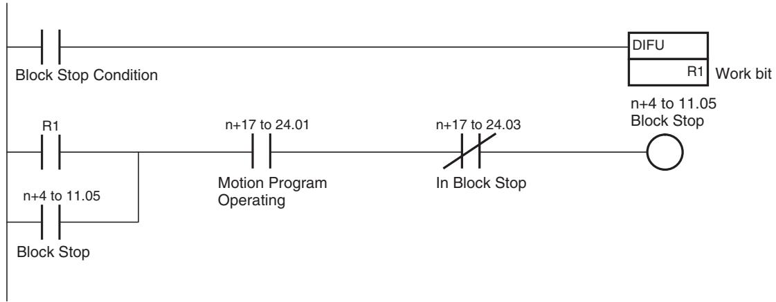
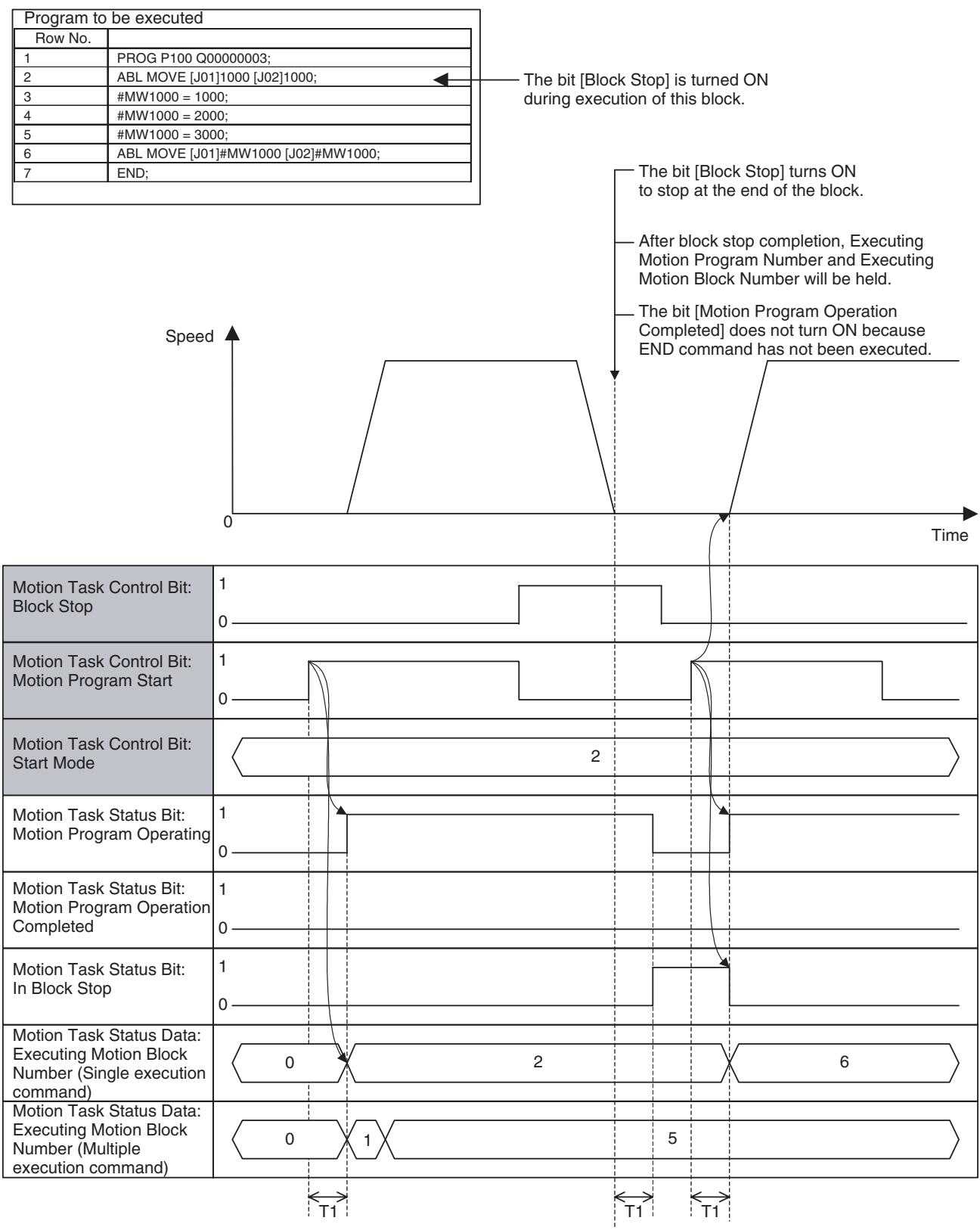
Timing Chart
Basic Operation:
Stop in Pass Mode:
| Program to be executed | |
| Row No. | |
| 1 | PROG P100 Q00000003; |
| 2 | PASSMODE; |
| 3 | MOVEL [J01]1000; |
| 4 | MOVEL [J02]1000; |
| 5 | END; |
The bit [Block Stop] is turned ON after starting execution of this block.
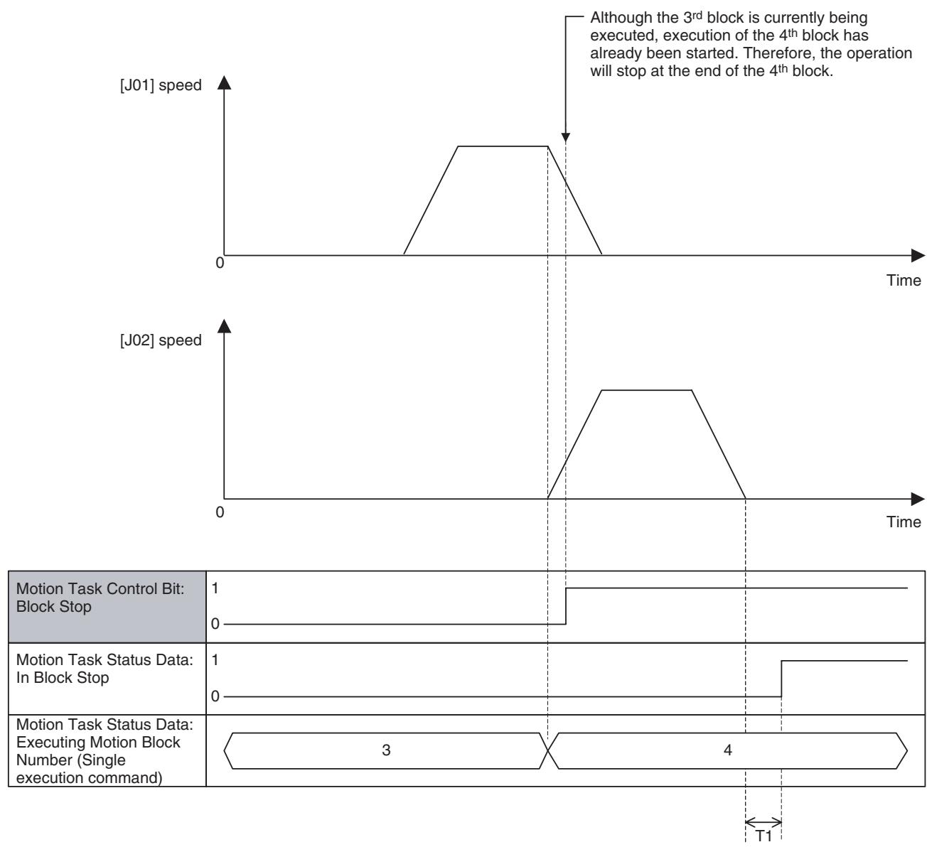
| Program to be executed | |
| Row No. | |
| 1 | PROG P100 Q00000003; |
| 2 | SPEED [J01]1000 T 100; |
| 3 | MOVEL [J02]1000; |
| 4 | END; |
The bit [Deceleration Stop] is turned ON after starting execution of this block.
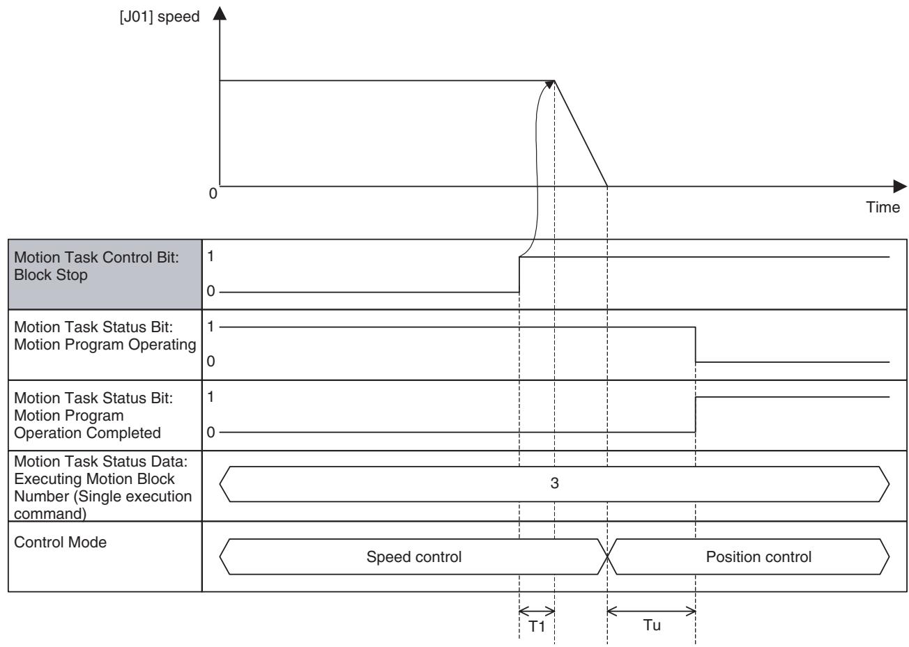
Stop in Speed or Torque control mode:
| Word | Variable | Bit | Name | I/O |
| n+4 | IW0340 | 06 | Single Block Operation Mode (Task 1) | Output |
| - | - | - | ||
| n+11 | IW0347 | Single Block Operation Mode (Task 8) |
Function
- Single block operation mode is used for debugging purpose, etc. to execute the motion program block by block.
- [Block Stop] and [Single Block Operation Mode] are similar from the viewpoint that the operation is stopped at the end of the block, however, following differences can be observed between them:
| Item | Block Stop | Single Block Operation |
| Purpose | Used to stop the motion program. | Used to debug the motion program. |
| Influence when starting execution | Motion program execution cannot be started while the bit [Block Stop] is ON. | Motion program execution can be started while the bit [Single Block Operation Mode] is ON. |
| Detection | Edge detection | Level detection |
| NSTOP command | Operation stops not being affected by NSTOP. | Operation does not stop being affected by NSTOP. |
Command and Operation
| Name | Specifications |
| Motion Program Start | 0: Nil1: Nil↑: Starts motion program operation following the specified Start Mode↓: No |
| Start Mode | 0,3: Reads program number and executes the program from top.1:Executes the program from the block indicated by Executing Motion Block Number. Operation at resuming interrupted pro-grams varies depending on the command used or stopping status.2:Executes the program continuously from the next block of the block indicated by Executing Motion Block Number. |
| Single Block Operation Mode | 0: Single Block Operation Mode OFF1: Single Block Operation Mode ON↑: Nil↓: Nil |
- If motion program execution is started while the bit [Single Block Operation Mode] is ON, only one block will be executed and the operation will be stopped with Block Stop.
- If [Single Block Operation Mode] is turned ON during motion program operation, the same operation as for that of [Block Stop] will occur.
- Different from the bit [Block Stop], the motion program can be executed even when the bit [Single Block Operation Mode] is ON.
- Different from the bit [Block Stop], the bit [Single Block Operation Mode] is checked only at the end of the block. Therefore, the operation will not stop at the end of the block if the bit is turned OFF before program execution reaches the end of the block.
- Turn on the bit [Motion Program Start] to resume the motion program in Block Stop state.
- When the bit [Motion Program Start] is turned ON, the bit [Start Mode] will be checked. The relations between actual debugging operation and Start Mode are described below:
| Debugging Operation | Start Mode |
| To proceed to the next block | Start Mode = 2 |
| To start over from the top | Start Mode = 0, 3 |
| To execute the same block that has just been executed again | Start Mode = 1 |
Status Condition
| Name | Specifications |
| Motion Program Operating | 0: Motion task is not executing program operation. 1: Motion task is executing program operation (turned OFF after completion of deceleration or block stop) |
| Motion Program Operation Completed | 0: When starting program operation 1: END command was executed. |
| In Block Stop | 0: Not in Block Stop 1: In Block Stop |
| Motion Program Number | Specifies program number to be executed in motion task. 0-499 |
| Executing Motion Program Number | Outputs the program number of the program currently being executed in motion task or temporarily being stopped. |
| Executing Motion Block Number (Single execution command) | • Outputs the block number of the single execution command currently being executed with motion task, or temporarily being stopped. • During execution of parallel branching, the block number of the leftmost block is output. |
| Executed Motion Block Number (Multiple execution command) | • Outputs the block number of the multiple execution command currently being executed with motion task, or temporarily being stopped. • During execution of parallel branching, the block number of the leftmost block is output. |
For details, see Motion Program Start and Start Mode on page 443.
Effect of Other Functions
Operation does not stop at the end of the block with [NSTOP command: Single block ignored] specification.
Effect on Other Functions Nil
System Parameter Nil
Program Example
n+4 to 11.06
Single Block Operation Mode
Single Block
Operation Condition
Timing Chart
Basic Operation:
| Program to be executed | |
| Row No. | |
| 1 | PROG P100 Q00000003; |
| 2 | ABL MOVE [J01]1000 [J02]1000; |
| 3 | #MW1000 = 1000; |
| 4 | #MW1000 = 2000; |
| 5 | #MW1000 = 3000; |
| 6 | ABL MOVE [J01]#MW1000 [J02]#MW1000; |
| 7 | END; |
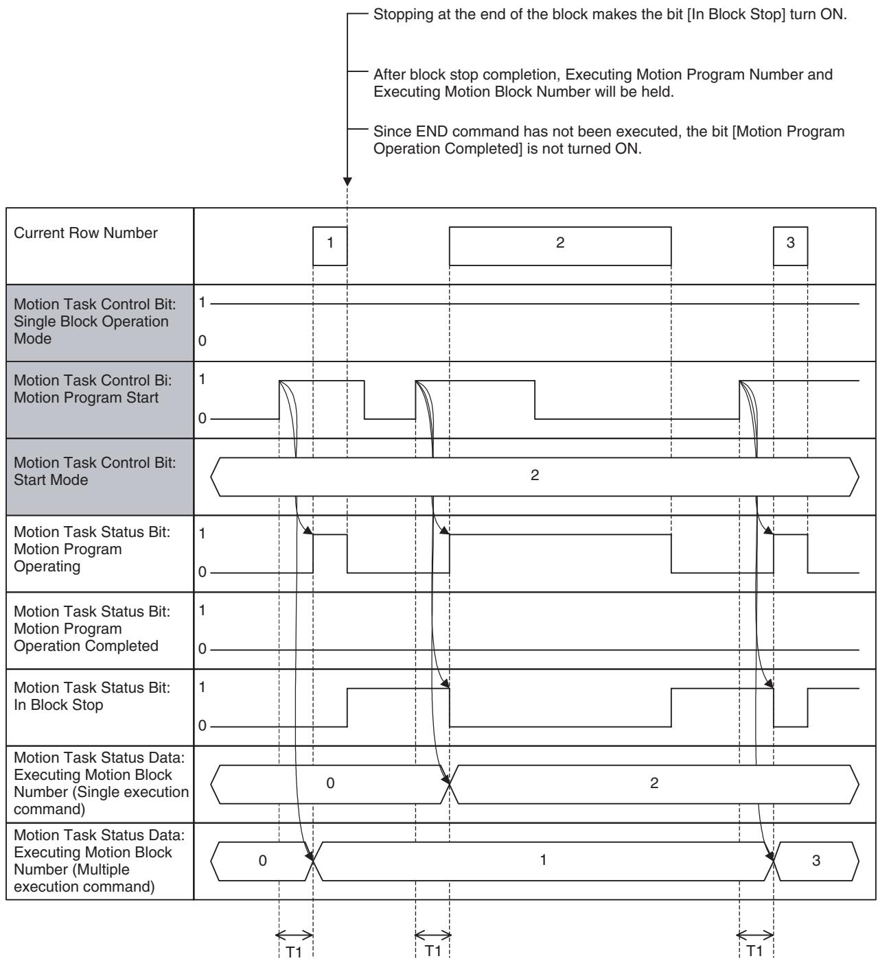
| Word | Variable | Bit | Name | I/O |
| n+4 | IW0340 | 07 | Task Override Enable (Task 1) | Output |
| - | - | - | ||
| n+11 | IW0347 | Task Override Enable (Task 8) |
Function
- Override is the function to change the feed rate specified in the motion program or parameter to the user-specified speed with % specification.
- There are three types of override, the task override, axis override, and internal override. They are used differently in motion program execution depending on the speed.
- The task override can be applied to the speed specified by operand F in the motion program.
The relations between each command and override are shown in the table below:
| Classification | Function/Name | Command | Override | Remark |
| Axis Movement | Positioning | MOVE | Axis OverrideInternal Over-ride | |
| Linear Interpolation | MOVEL | Task Override | ||
| Circular Interpolation | MOVEC | Task Override | ||
| Origin Search | DATUM | Axis Override | Applicable only for origin search feed rate | |
| Interrupt Feeding | MOVEI | Axis OverrideInternal Over-ride | ||
| Time-specified Positioning | MOVET | Axis OverrideInternal Over-ride | Specified time period will not be kept. | |
| Traverse | MOVETRAV | Task Override | ||
| Electronic Cam, Single Axis | CAM | Disable | ||
| Axis Operation | Link Operation | MOVELINK | Disable | |
| Electronic Cam, Synchronous | CAMBOX | Disable | ||
| Electronic Shaft | CONNECT | Disable | ||
| Trailing Synchronization | SYNC | Disable | ||
| Travel Distance Superimpose | ADDAX | Disable | ||
| Speed Control | SPEED | Disable | ||
| Torque Control | TORQUE | Disable | ||
| Axis Operation Cancel | Trailing Synchronous Cancel | SYNCR | Disable | |
| Travel Distance Superimpose Cancel | ADDAXR | Disable | ||
| Speed Control Cancel | SPEEDR | Disable | ||
| Torque Control Cancel | TORQUER | Disable |
Command and Operation
| Name | Specifications |
| Task Override Enable | 0: Enables axis override value (override 100% is used.)1: Enables axis override value↑: Nil↓: Nil |
| Task Override | 0 to 32767 [0.01%]0.00% if value out of range is input. |
- The value in [Task Override] is enabled only while the bit [Task Override Enable] is turned ON. When the bit is OFF, override 100.00% is used.
- The bit [Task Override Enable] and data [Task Override] are always referenced.
Status Condition Nil
Effect of Other Functions Nil
Effect on Other Functions Speed of the functions with axis movement is affected.
Program Example
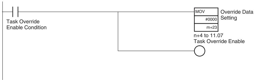
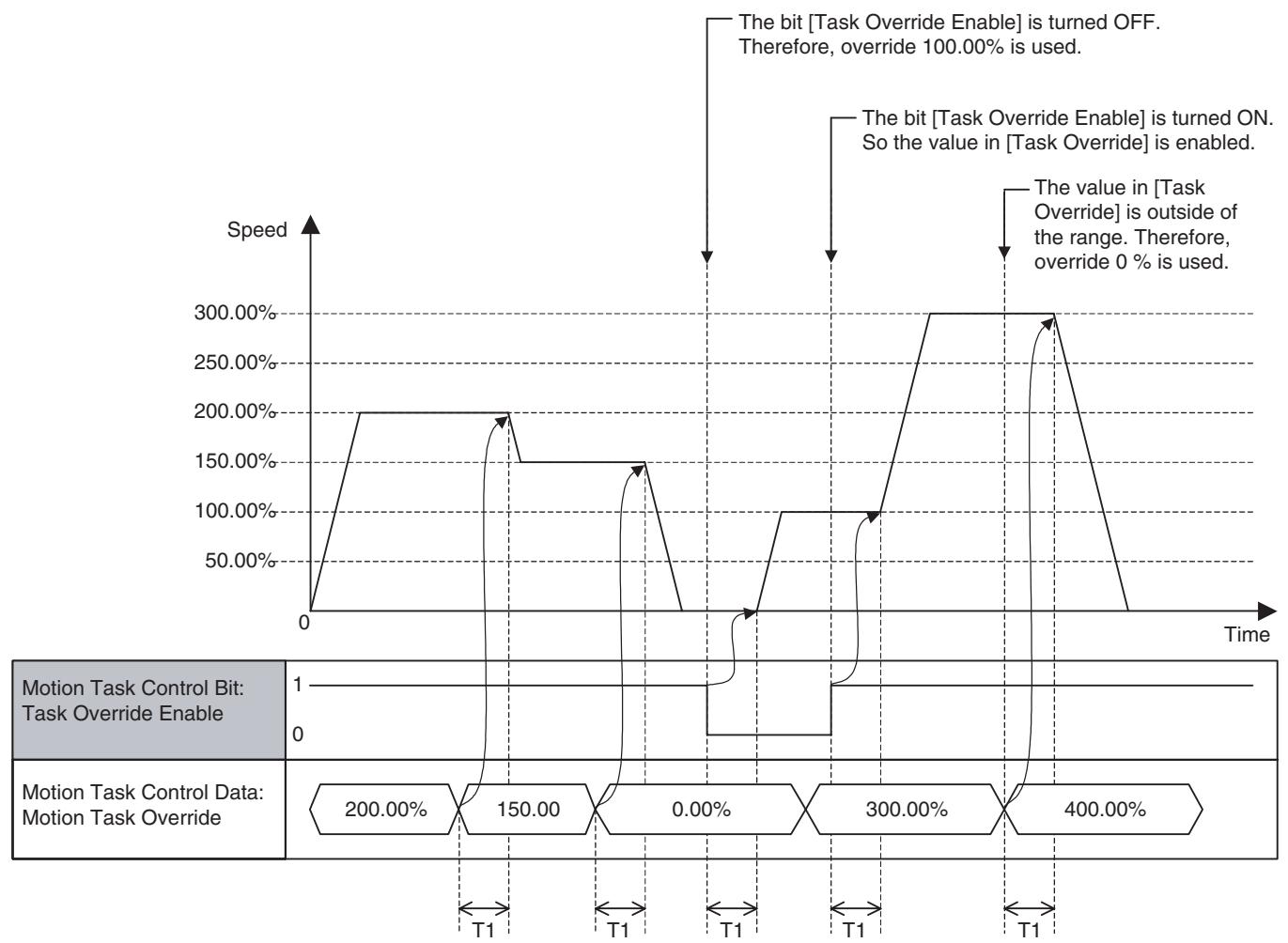
Timing Chart Basic Operation:
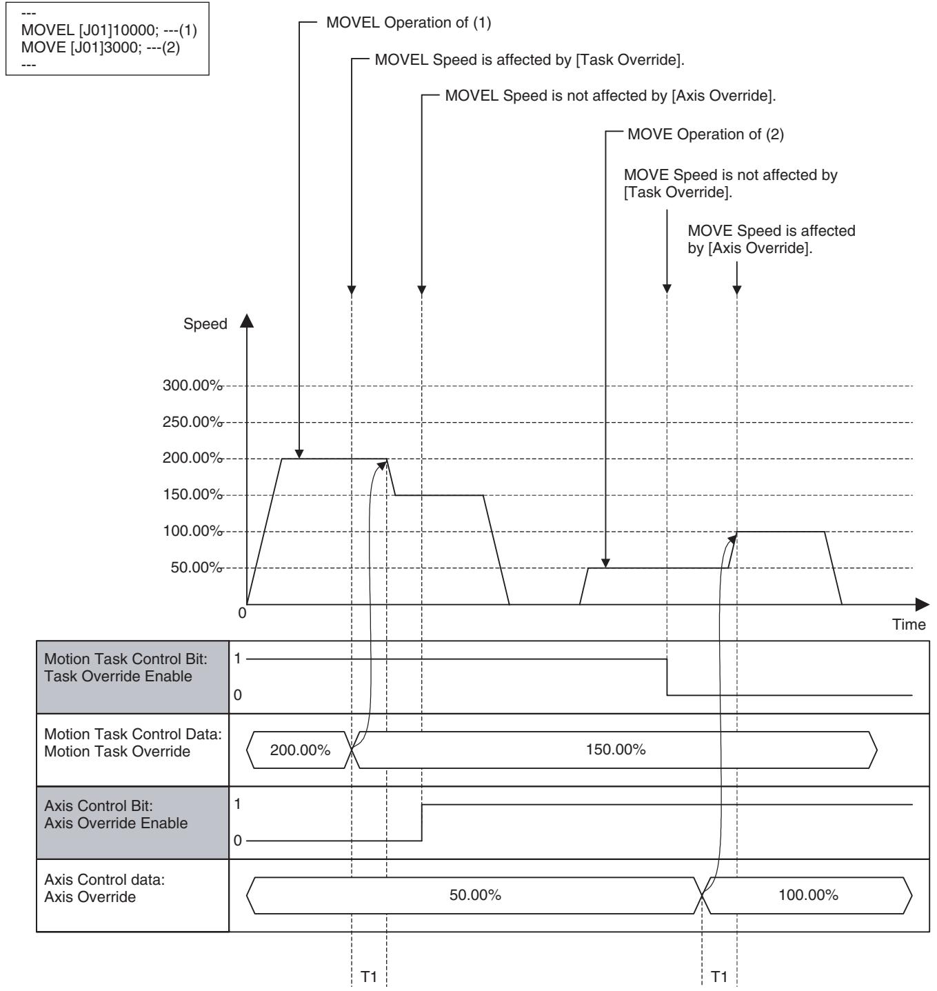
Relation between Task Override and Axis Override:
Program Example
| Word | Variable | Bit | Name | I/O |
| n+4 | IW0340 | 00 | Motion Task Alarm Reset (Task1) | Output |
| - | - | - | ||
| n+11 | IW0347 | Motion Task Alarm Reset (Task8) |
Function
When an error that requires stopping operation occurs in the MC Unit, it is detected as an alarm.
Removing the cause and executing alarm reset can clear the alarms that occurred, except for some alarms.
Command and Operation
| Name | Specifications |
| Motion Task Alarm Reset | 0: Nil1: Does not turn ON the bit [Motion Task Alarm].↑: Clears the alarm occurring in motion task.↓: Nil |
Turning ON the bit [Motion Task Alarm Reset] can reset alarms on the motion task level.
Status Condition
| Name | Specifications |
| Alarm Occurring | 0: No alarm 1: Alarm occurring in MC Unit (linked to ERC indicator) |
| Motion Task Alarm Occurring 1-8 | 0: No alarm occurring in motion task. 1: Alarm occurring in motion task. |
| Motion Task Alarm | 0: No alarm in motion task, or on the axis level. Otherwise, the bit [Motion Task Alarm Reset] is ON. 1: Alarm occurring in motion task, or on the axis level. |
| Motion Task Alarm Code | Outputs the code of the alarm occurring in motion task. |
- When an alarm occurs on the motion task level, the bits [Alarm Occurring], [Motion Task Alarm Occurring 1-8] and [Motion Task Alarm] will be turned ON, and then the alarm code will be stored in [Motion Task Alarm Code].
- If several alarms occur, the alarm code detected first will be stored in Motion Task Alarm Code.
Effect of Other Functions
Nil
Effect on Other Functions
When an alarm occurs, it affects other functions (operation failure, operation interruption, etc.)
System Parameter
Nil
Program Example

On MC Unit, there are three types of alarms:
Unit alarm
- Task alarm
- Axis alarm
Alarms are reset on the basis of each type. Therefore, execute the alarm reset over the Unit, Task, and Axis to clear an alarm occurring on the MC Unit without fail.
Timing chart
Basic Operation (Alarm Occurring):
| Alarm Identification: Alarm Occurring | 1 0 |
| Alarm Identification: Motion Task Alarm Occurring | 1 0 |
| Motion Task Status Bit: Motion Task Alarm | 1 0 |
| Motion Task Status Data: Motion Task Alarm Code | XXXX |
| Internal Alarm Status | 1 0 |
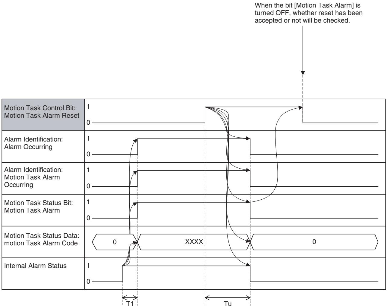
Basic Operation (Alarm Reset):
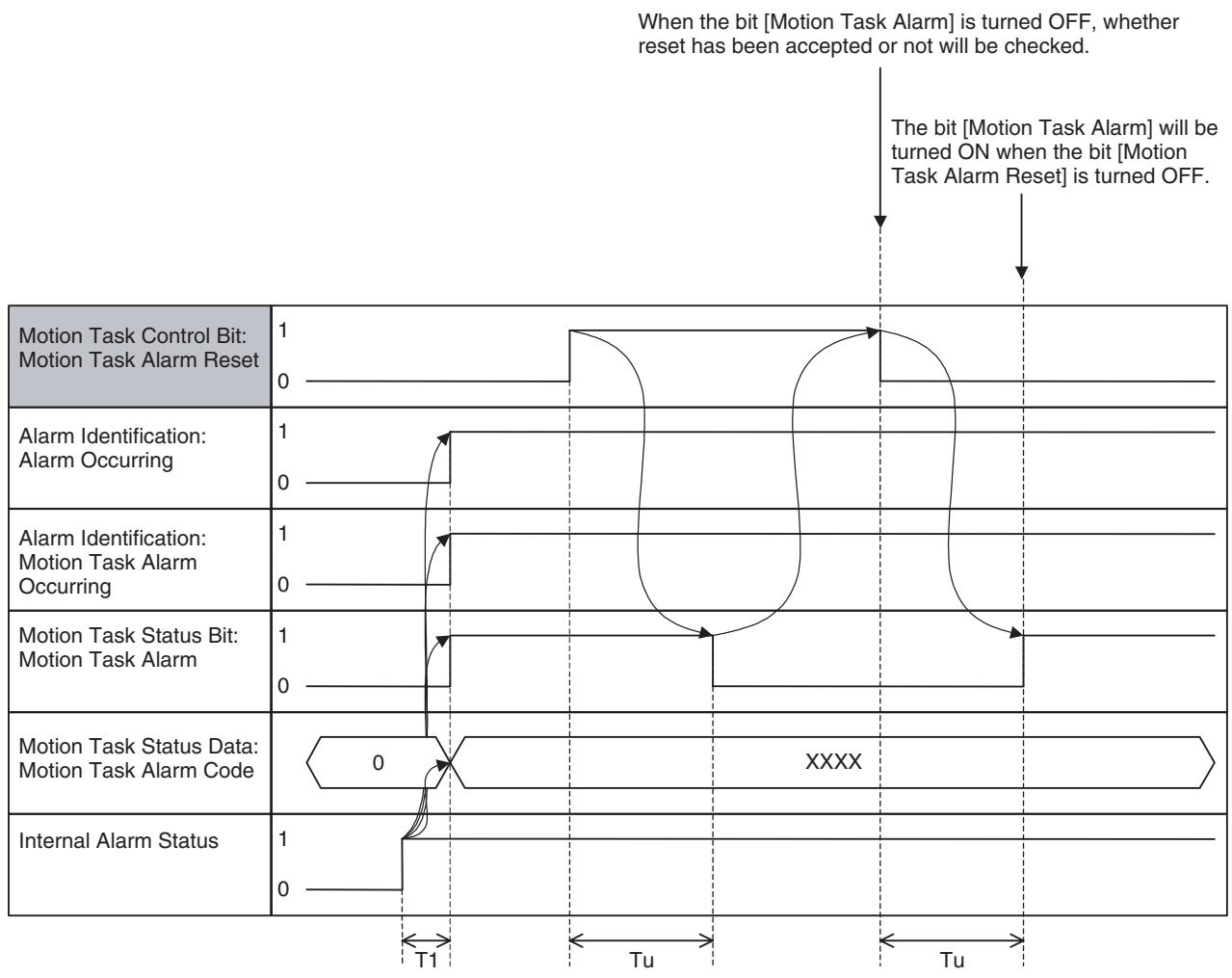
When an alarm that cannot be reset occurs:
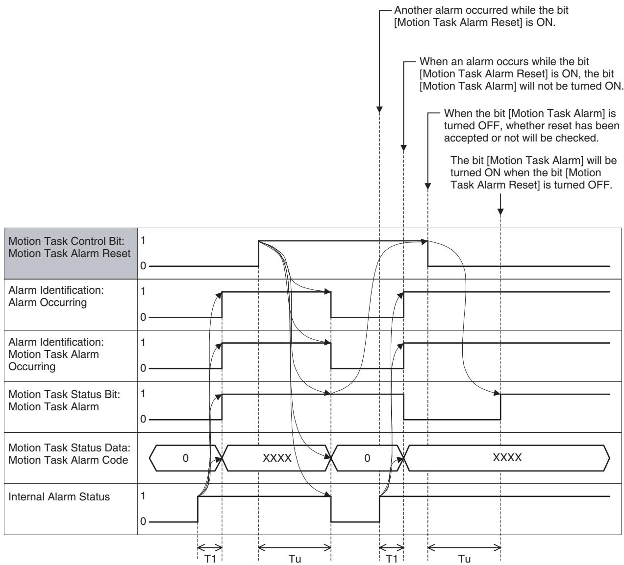
| Word | Variable | Bit | Name | I/O |
| n+17 | OW0340 | 04 | Speed Clamp Warning (Task 1) | Input |
| - | - | - | ||
| n+24 | OW0347 | Speed Clamp Warning (Task 8) |
Function
The bit [Speed Clamp Warning] indicates the status that the speed specified in the motion program and multiplied by an override value was limited and could not be output.
Status Condition
| Name | Specifications |
| Speed Clamp Warning | 0: Speed not limited 1: Speed limited by the maximum speed setting |
| Start Warning | 0: Started motion program operation successfully 1: Could not start motion program operation (Axis declaration, Axis mode) |
1-shot output may occur. In that case, depending on the Scan Time of the ladder program and the Unit Scan Time of the MC Unit, the output may not be reflected in the ladder program.
Effect of Other Functions
Nil
System Parameter
ON/OFF of the bit [Speed Clamp Warning] is determined by the following system parameters:
| Parameter No. | Name |
| P00M01 | Maximum interpolation feed rate |
| P2AA01 | Maximum rapid feed rate |
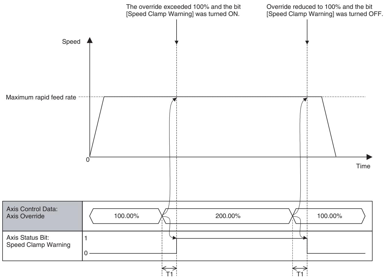
Timing Chart
Basic Operation:
| Word | Variable | Bit | Name | I/O |
| n+17 | OW0340 | 05 | Start Warning (Task 1) | Input |
| - | - | - | ||
| n+24 | OW0347 | Start Warning (Task 8) |
Function
The bit [Start Warning] indicates the status that the execution start condition was not satisfied when starting motion program execution.
Status Condition
| Name | Specifications |
| Start Warning | 0: Started motion program operation successfully. 1: Could not start motion program operation (Axis declaration, Axis mode) |
- The bit [Start Warning] is turned ON in the following cases and it will be turned OFF when motion program operation is started successfully.
-
The bit [Deceleration Stop] or [Block Stop] is ON.
-
[Motion Program Number] is not between 0-499.
- The motion program specified by [Motion Program Number] does not exist (It has not been loaded).
- The bit [Command Disable/Enable] of the axis specified by PROG command is OFF.
- The bit [Axis Not Used/Used] of the axis specified by PROG command is ON.
- The bit [Manual/Automatic Mode] of the axis specified by PROG command is OFF.
- A unit alarm, motion task alarm, or an alarm of the axis specified by PROG command is occurring, or the bit [External Forced Stop Request] is ON.
Effect on Other Functions Nil
System Parameter Nil
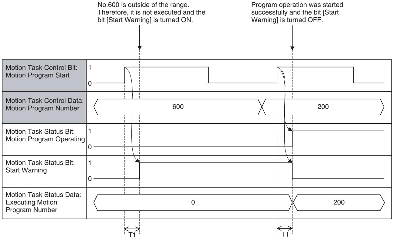
Timing Chart
| Word | Variable | Bit | Name | I/O |
| n+17 | OW0340 | 06 | Start Bit (Task 1) | Input |
| - | - | - | ||
| n+24 | OW0347 | Start Bit (Task 8)(Supported in Unit Ver. 3.0 or later) |
Function
The bit [Start] indicates the ON/OFF status of the bit [Motion Program Operating].
Status Condition
| Name | Specifications |
| Start | 0: Motion Program Operating Bit OFF (0).1: Motion Program Operating Bit ON (1). |
Effect of Other Functions Nil
System Parameter Nil
Timing Chart
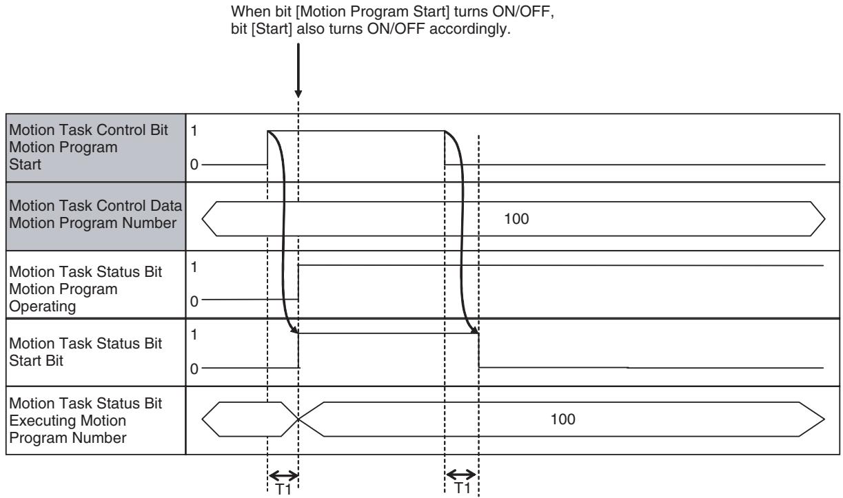
7-4-4 Axis Control Bits, Axis Status Bits
| Word | Variable | Bit | Name | I/O |
| x+0 | IW0440 | 01 | Deceleration Stop (Axis 1) | Output |
| - | - | - | ||
| x+31 | IW045F | Deceleration Stop (Axis 32) |
Function
The function is used for each function on the axis level as the interlock by interruption with a deceleration stop or ON state of the bit.
Command and Operation
| Name | Specifications |
| Deceleration Stop | 0: Nil1: Prohibits JOG, STEP, and Origin Search in Manual Mode.↑: Deceleration stop (JOG, STEP, and Origin Search)↓: Nil |
- When the bit [Deceleration Stop] is turned ON, the operation of each function in the table below will be stopped with deceleration.
- When the bit [Deceleration Stop] is ON, execution of each function in the table below will be prohibited.
| Operation | At rising edge | ON |
| Axis Control Bit: JOG | Decelerated to stop | Execution prohibited |
| Axis Control Bit: STEP | Decelerated to stop | Execution prohibited |
| Axis Control Bit: Origin Search | Decelerated to stop | Execution prohibited |
| Axis Control Bit: Machine Origin Return | Decelerated to stop | Execution prohibited |
| Axis Control Bit: Forced Origin | Not influenced | Execution prohibited |
| Axis Control Bit: ABS Origin Setting | Not influenced | Execution prohibited |
| IOWR: Present Position Preset | Not influenced | Execution prohibited |
- Turning ON the bit [Deceleration Stop] after having started deceleration stop operation will not interrupt deceleration stop operation.
Status Condition Nil
Effect of Other Functions Nil
Effect on Other Functions Nil
System parameter Nil
Program Example
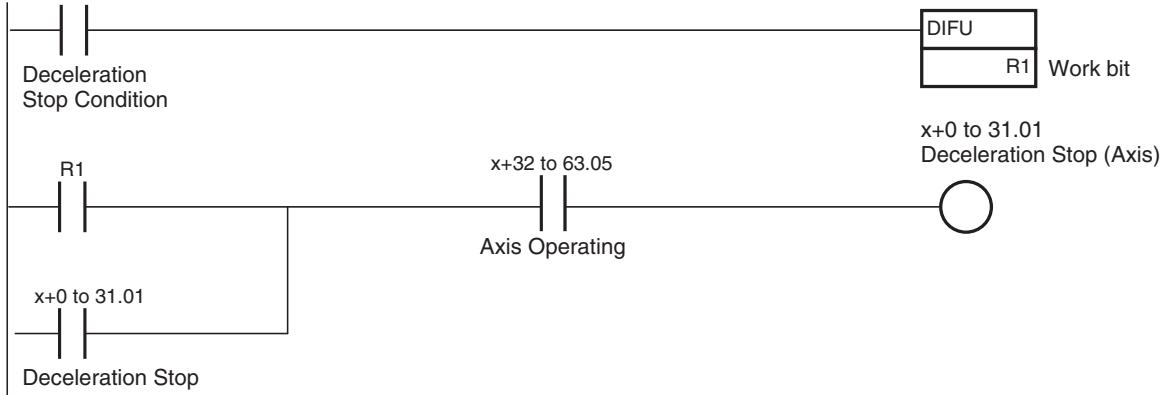
Timing Chart
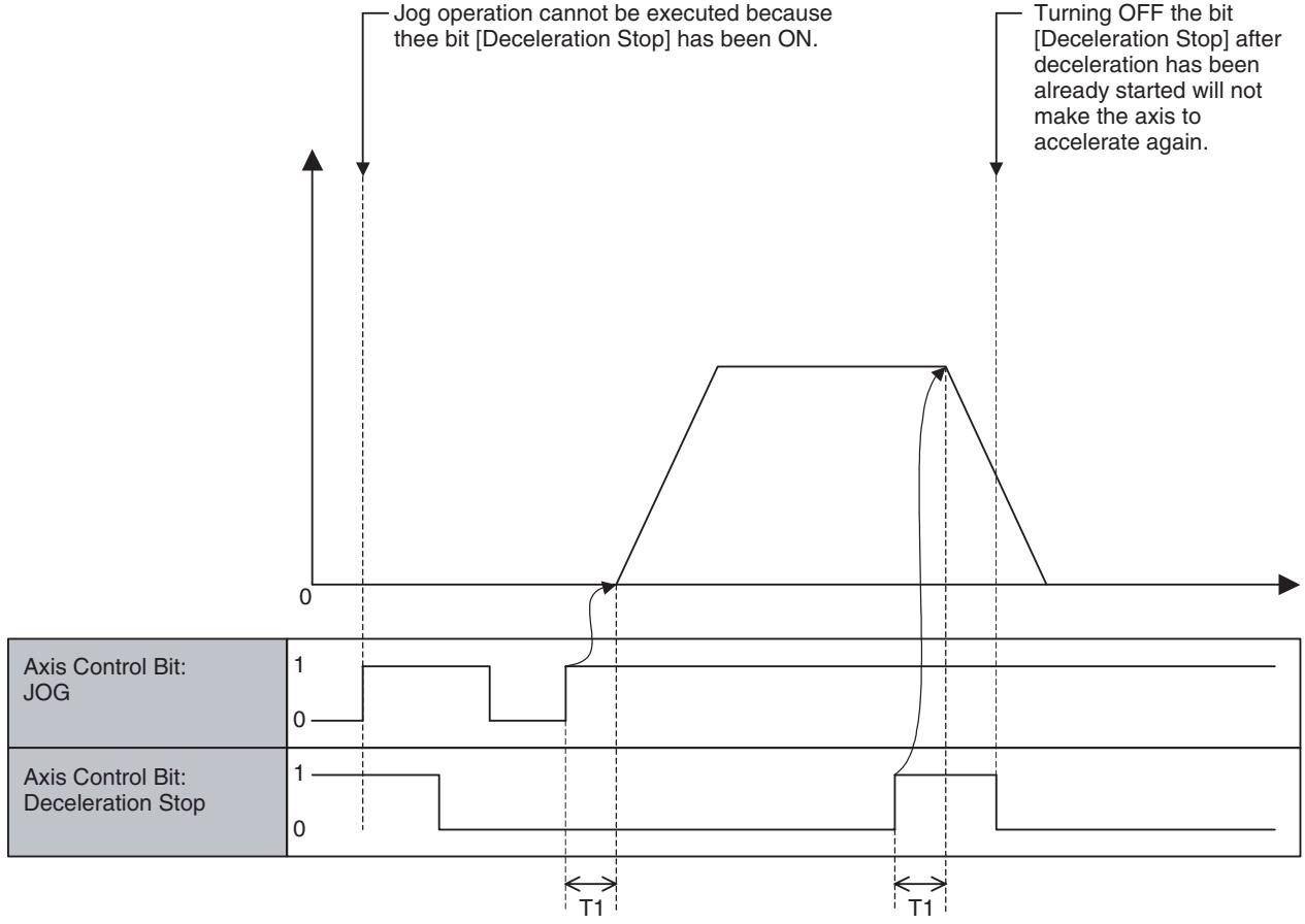
| Word | Variables | Bits | Name | I/O |
| x+0 | IW0440 | 02 | Servo Lock (Axis 1) | Output |
| -x+31 | - | Servo Lock (Axis 32) | ||
| IW045F | 03 | Servo Unlock (Axis 1) | Output | |
| Servo Unlock (Axis 32) |
Function
This is the function to lock (Servo ON) or unlock (Servo OFF) the servo.
Command and Operation
| Name | Specifications |
| Servo Lock | 0: Nil1: Nil↑: Starts Servo Lock↓: Nil |
| Servo Unlock | 0: Nil1: Prohibits Servo Lock↓: Cancels Servo Lock state↓: Nil |
- Servo is locked when the bit [Servo Lock] is turned ON, and Servo is unlocked when the bit [Servo Unlock] is turned ON.
- While the bit [Servo Unlock] is ON, the bit [Servo Lock] is ignored.
- Turning ON the bit [Servo Unlock] after the bit [Servo Lock] has been already turned ON will interrupt the Servo Lock operation to unlock Servo.
- Once the bit [Servo Lock] is turned ON, the processing will not be interrupted (i.e. the bit [In Servo Lock] will turn ON) even if the bit [Servo Lock] is turned OFF before the rise of the bit [In Servo Lock].
- Similarly, once the bit [Servo Unlock] is turned ON, the processing will not be interrupted (i.e. the bit [In Servo Lock] will turn OFF) even if the bit [Servo Unlock] is turned OFF before the rise of the bit [In Servo Lock].
Status Condition
| Bit | Name | Specifications |
| 03 | In Servo Lock | 0: In Servo Unlock state1: In Servo Lock state |
Servo Lock status (ON/OFF status) is output to the bit [In Servo Lock].
Effect of Other Functions
| Classification | Item | Effect |
| Physical Status | Servo Axis | No effect |
| Virtual Axis | No effect | |
| I/O Axis | Ignored | |
| Counter Axis | Ignored | |
| Status Bits | Busy | No effect |
| Servo Lock | No effect | |
| No Origin | No effect | |
| Axis Operating | No effect | |
| Positioning Completed | No effect | |
| Positioning Completed (No.2) | No effect | |
| Axis Machine Lock Status | No effect | |
| Command Disable/Enable | Servo Lock/Unlock cannot be executed when OFF. | |
| Axis Not Used/Used | No effect | |
| In Manual/Automatic Mode | No effect |
Effect on Other Functions
The functions in the following table cannot be executed when the bit [In Servo Lock] is OFF.
| Function |
| Axis Control Bit: JOG |
| Axis Control Bit: STEP |
| Axis Control Bit: Origin Search |
| Axis Control Bit: Machine Origin Return |
| Other commands with axis movement |
System Parameter
Nil
Program Example
Example 1
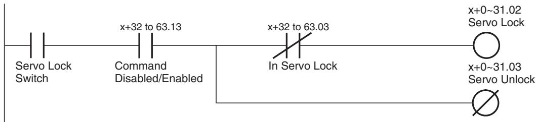
Example 2
With Unit Ver. 3.0 or later, the Servo Driver main circuit ON/OFF status is output in the axis status area. In this example, the ON/OFF status of the main circuit is combined with an AND condition to ensure a Servo Lock status.
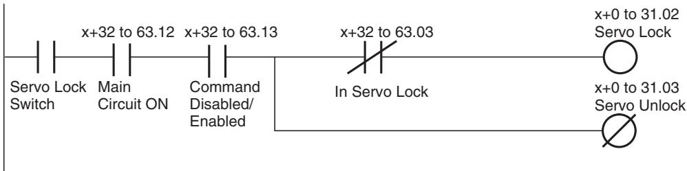
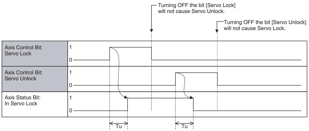
Timing Chart
Basic Operation:
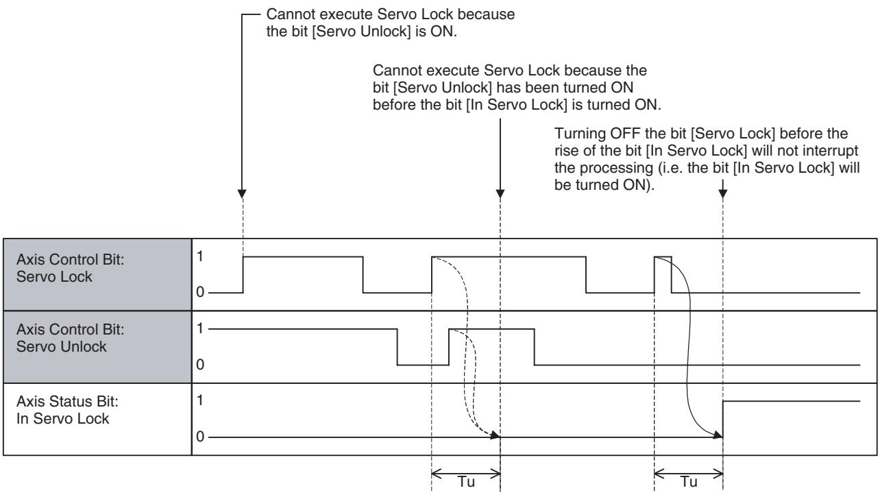
Servo Unlock:
| Word | Variable | Bit | Name | I/O |
| x+0 | IW0440 | 04 | JOG Operation (Axis 1) | Output |
| - | - | - | ||
| x+31 | IW045F | JOG Operation (Axis 32) |
Function
- The axis is moved while the bit [JOG Operation] stays ON.
- [Axis Override] is applied to the speed. For details of timing, etc., see "Relation between Task Override and Axis Override" (page 462).
Command and Operation
| Name | Specifications |
| JOG | 0: Nil1: Continues JOG operation↑: Starts JOG operation↓: Stops JOG operation |
| JOG/STEP Direction | 0: Sets the direction of JOG and STEP operation to positive direction1: Sets the direction of JOG and STEP operation to negative direction↑: Nil↓: Nil |
- Acceleration will be started when the bit [JOG Operation] is turned ON, and deceleration will be started when the bit [JOG Operation] is turned OFF.
Operation Direction
- The operation direction is changed using the method set in system parameter P00004, bit 05 (unit function selections, direction switching method for JOG operation). Refer to page 480 for details.
Status Condition
| Name | Specifications |
| Busy | 0: Not executing any of the functions listed below.1: Executing one of the functions listed below, or the command bit is ON.JOG, STEP, Origin Search, Machine Origin Return, Error Counter Reset, Forced Origin, and ABS Origin Setting |
| Axis Operating | 0: No axis operating command1: Axis operating command being output. |
| Positioning Com-pleted | 0: Outputting positioning command, or axis is outside of in-position range.1: Not outputting positioning command, and axis is within in-position range. |
| Axis Not Used/Used | 0: Axis is not being used.1: Axis is being used.(In Manual Mode: Axis is used for JOG etc., In Automatic Mode: Axis is declared in the operating program) |
Effect of Other Functions
| Classification | Item | Effect |
| Physical Status | Servo Axis | No effect |
| Virtual Axis | No effect | |
| I/O Axis | Ignored | |
| Counter Axis | Ignored | |
| Status Bits | Busy | JOG cannot be executed when ON. |
| In Servo Lock | JOG cannot be executed when OFF. | |
| No Origin | No effect | |
| Axis Operating | JOG cannot be executed when ON. | |
| Positioning Completed | No effect | |
| Positioning Completed (No.2) | No effect | |
| Axis Machine Lock Status | No effect | |
| Command Disabled/Enabled | JOG cannot be executed when OFF. | |
| Axis Not Used/Used | JOG cannot be executed when ON. | |
| In Manual/Automatic Mode | JOG cannot be executed when ON. |
Effect on Other Functions System Parameter
Nil
The settings of the following parameters determines the speed pattern:
| Parameter No. | Name |
| P2AA02 | Maximum manual feed rate |
| P2AA04 | Manual feed rate |
| P2AA07 | Manual feed acceleration time |
| P2AA08 | Manual feed deceleration time |
| P2AA10 | Manual feed acceleration/deceleration type |
| P2AA12 | Manual feed S-curve time constant |
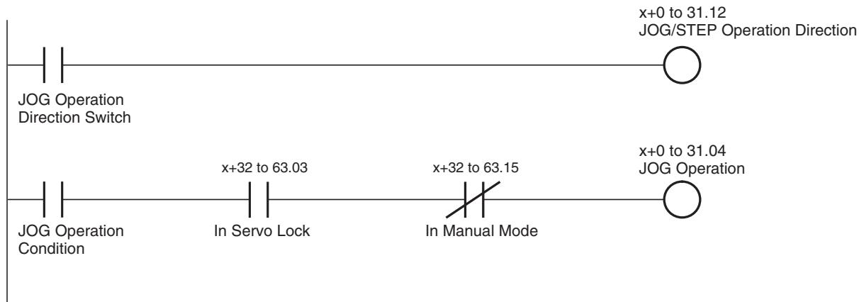
Program Example
Timing Chart
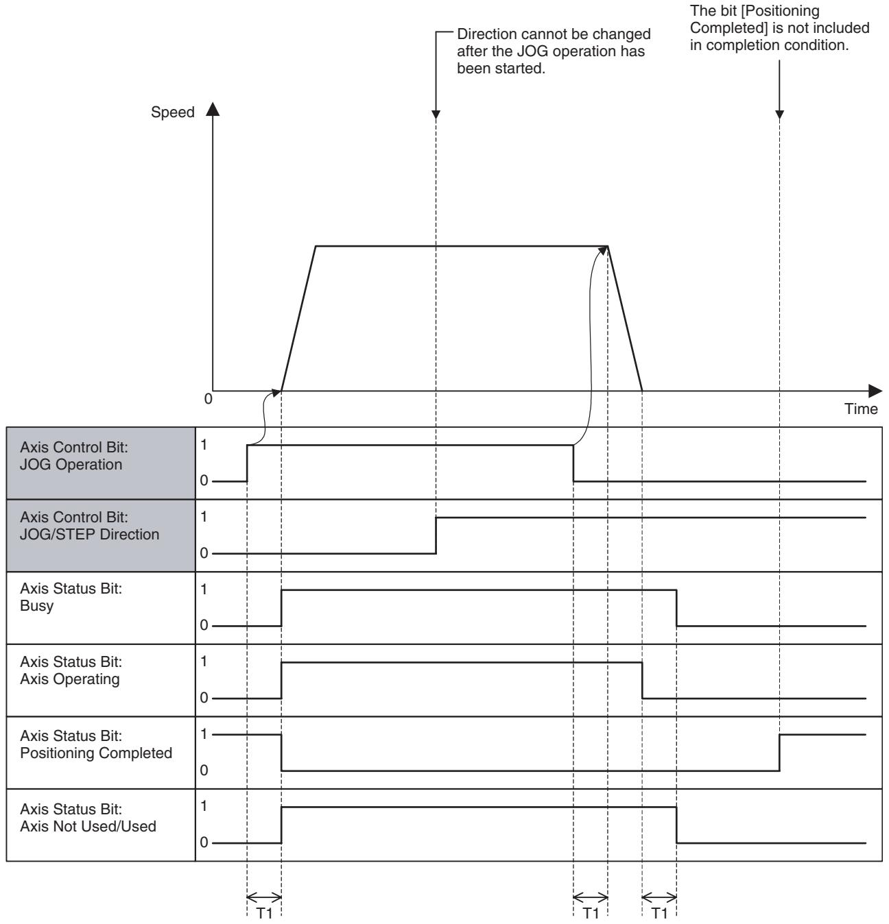
P00004 bit 05 set to 0
Basic Operation:
Timing Chart
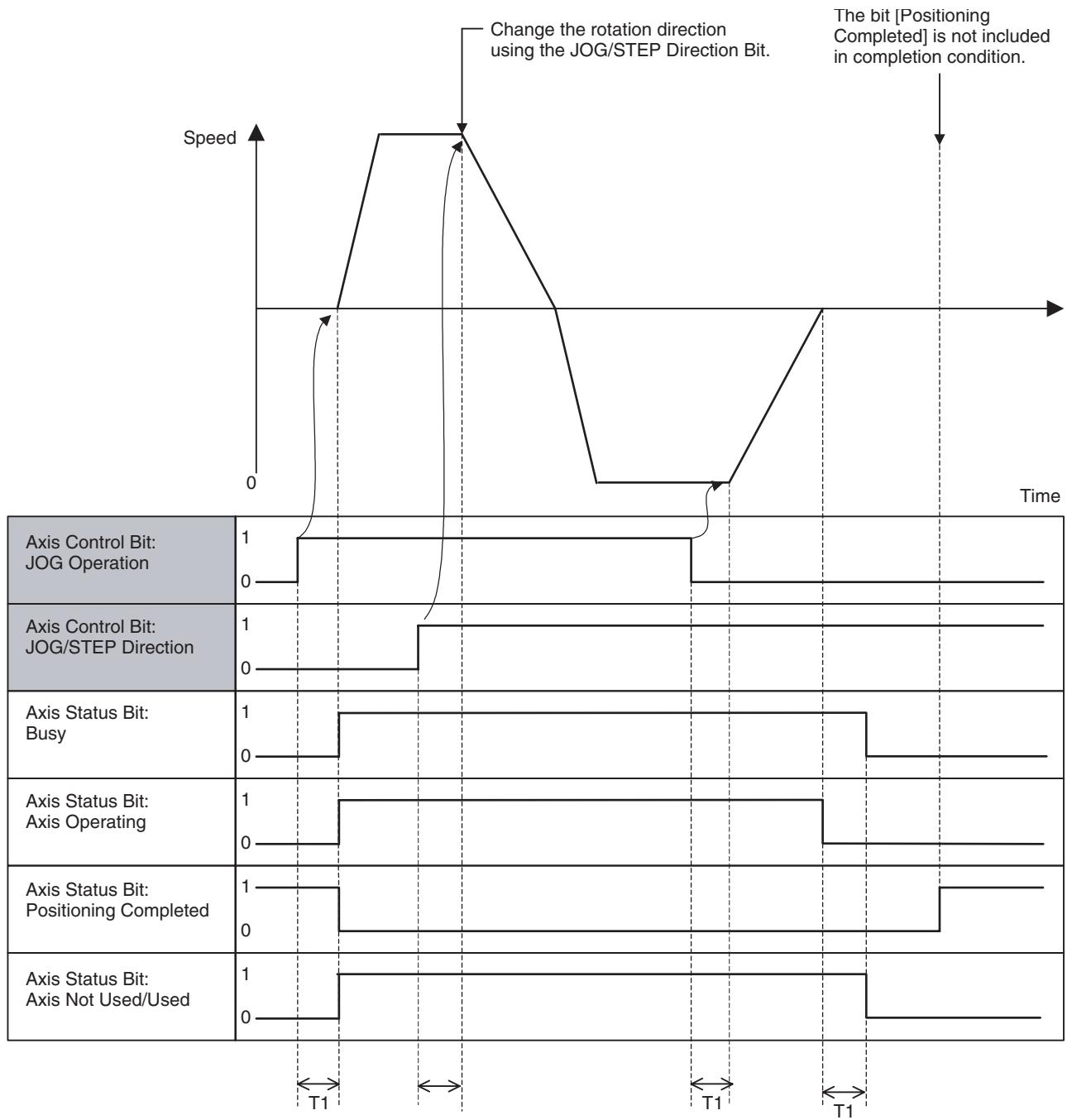
P0004 bit 05 set to 1
Basic Operation:
| Word | Variable | Bit | Name | I/O |
| x+0 | IW0440 | 05 | STEP Operation (Axis 1) | Output |
| - | - | - | ||
| x+31 | IW045F | STEP Operation (Axis 32) |
Function
-
The axis will be moved for the specified travel distance when the bit [STEP Operation] is turned ON.
-
When the axis completes to move for the specified travel distance, it automatically decelerates to stop.
(The travel distance for the deceleration stop is included in the specified travel distance.) - [Axis Override] is applied to the speed. For details of timing, etc., see Relation between Task Override and Axis Override (page 462).
Command and Operation
| Name | Specifications |
| STEP | 0: Nil1: Continues STEP operation↑: Starts STEP operation↓: Stops STEP operation |
| JOG/STEP Direction | 0: Sets the direction of JOG and STEP operation to positive direction.1: Sets the direction of JOG and STEP operation to negative direction.↑: Nil↓: Nil |
- Acceleration will be started when the bit [STEP Operation] is turned ON. Even if the axis has not moved for the specified travel distance, it decelerates to stop when the bit [STEP Operation] is turned OFF.
- The bit [JOG/STEP Direction] determines the operation direction when the bit [STEP Operation] is turned ON. The operation direction cannot be changed during operation.
Status Condition
| Name | Specifications |
| Busy | 0: Not executing any of the functions listed below.1: Executing one of the functions listed below, or the command bit is ON.JOG, STEP, Origin Search, Machine Origin Return, Error Counter Reset, Forced Origin, and ABS Origin Setting |
| Axis Operating | 0: No axis operating command1: Axis operating command being output. |
| Positioning Com-pleted | 0: Outputting positioning command, or axis is outside of in-position range.1: Not outputting positioning command, and axis is within in-position range. |
| Axis Not Used/Used | 0: Axis is not being used.1: Axis is being used.(In Manual Mode: Axis is used for JOG etc., In Automatic Mode: Axis is declared in the operating program) |
Effect of Other Functions
| Classification | Item | Effect |
| Physical Status | Servo Axis | No effect |
| Virtual Axis | No effect | |
| I/O Axis | Ignored | |
| Counter Axis | Ignored | |
| Status Bits | Busy | STEP cannot be executed when ON. |
| In Servo Lock | STEP cannot be executed when OFF. | |
| No Origin | No effect | |
| Axis Operating | STEP cannot be executed when ON. | |
| Positioning Completed | No effect | |
| Positioning Completed (No.2) | No effect | |
| Axis Machine Lock Status | No effect | |
| Command Disabled/Enabled | STEP cannot be executed when OFF. | |
| Axis Not Used/Used | STEP cannot be executed when ON. | |
| In Manual/Automatic Mode | STEP cannot be executed when ON. |
Effect on Other Functions
System Parameter
Nil
The settings of the following system parameters determine the speed pattern and STEP operation travel distance:
| Parameter No. | Name |
| P2AA02 | Maximum manual feed rate |
| P2AA04 | Manual feed rate |
| P2AA07 | Manual feed acceleration time |
| P2AA08 | Manual feed deceleration time |
| P2AA10 | Manual feed acceleration/deceleration type |
| P2AA12 | Manual feed S-curve time constant |
| P3AA01 | STEP operation travel distance |
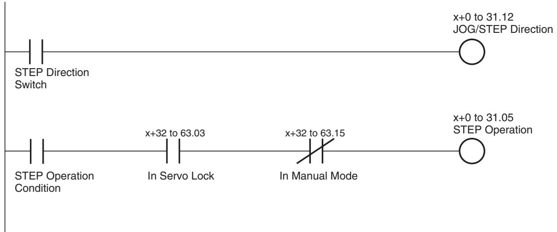
Program Example
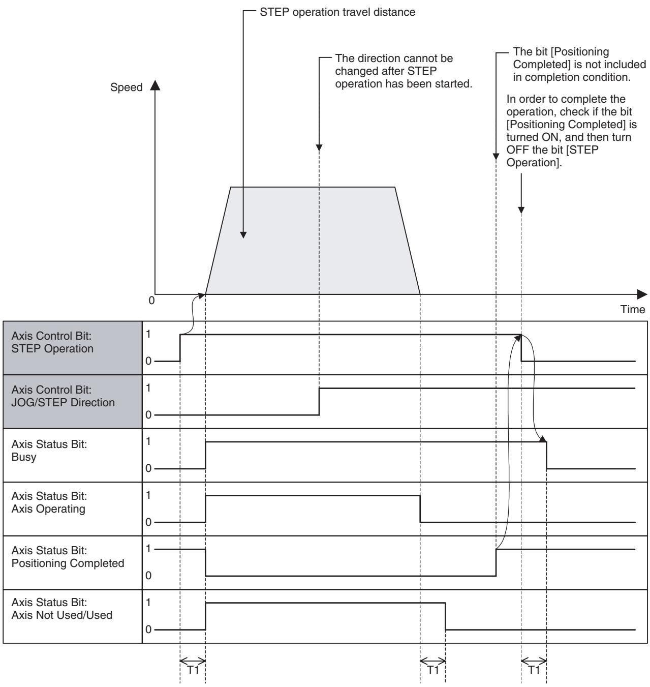
Timing Chart
Basic Operation:
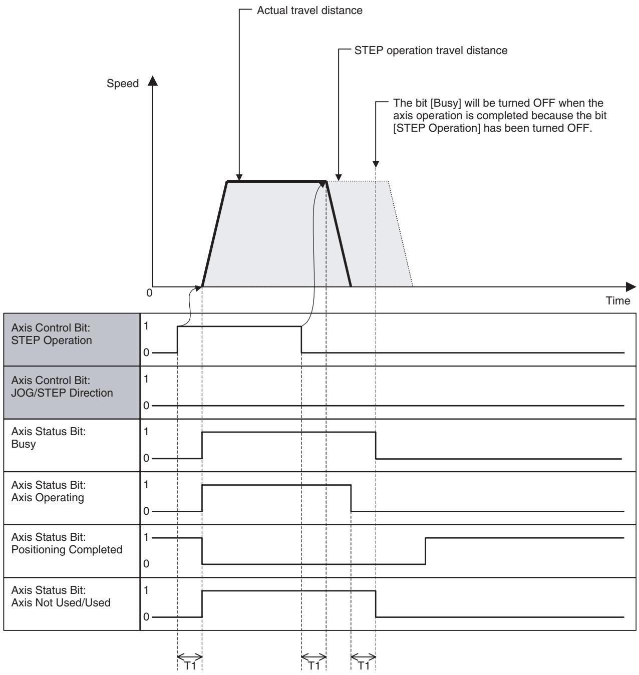
Premature completion:
| Word | Variable | Bit | Name | I/O |
| x+0 | IW0440 | 06 | Origin Search (Axis 1) | Output |
| - | - | - | ||
| x+31 | IW045F | Origin Search (Axis 32) |
Function
- With this function, the axis searches for the machine origin using the specified external signal or phase-Z.
- When the machine origin is detected, the axis will automatically decelerate to stop. [Axis Override] is applied to the origin search feed rate. For details about timing, etc., see Relation between Task Override and Axis Override (page 462).
- Override cannot be used for Origin search approach speed and Origin search creep speed.
Command and Operation
| Name | Specifications |
| Origin Search | 0: Nil1: Continues Origin search↑: Starts Origin search↓: Stops Origin search |
Origin search operation will be started when the bit [Origin Search] is turned ON. Even if the machine origin is not detected, the axis decelerates to stop when the bit is turned OFF.
Status Condition
| Name | Specifications |
| Machine Origin | 0: Machine coordinate system FB position is outside of origin in-position range. 1: Machine coordinate system FB position is within origin in-position range. |
| Busy | 0: Not executing any of the functions listed below. 1: Executing one of the functions listed below, or the command bit is ON. JOG, STEP, Origin Search, Machine Origin Return, Error Counter Reset, Forced Origin, and ABS Origin Setting |
| No Origin | 0: Origin on machine coordinate system is defined. 1: Origin on machine coordinate system is not defined. |
| Axis Operating | 0: No axis operating command 1: Axis operating command being output. |
| Positioning Com-pleted | 0: Outputting positioning command, or axis is outside of in-position range. 1: Not outputting positioning command, and axis is within in-position range. |
| Axis Not Used/Used | 0: Axis is not being used. 1: Axis is being used. (In Manual Mode: Axis is used for JOG etc., In Automatic Mode: Axis is declared in the operating program) |
Effect of Other Functions
| Classification | Item | Effect |
| Physical Status | Servo Axis | No effect |
| Virtual Axis | Performs the same operation as [Machine Origin Return] | |
| I/O Axis | Ignored | |
| Counter Axis | Ignored | |
| Status Bits | Busy | Origin search cannot be executed when ON. |
| In Servo Lock | Origin search cannot be executed when OFF. | |
| No Origin | No effect | |
| Axis Operating | Origin search cannot be executed when ON. | |
| Positioning Completed | Being ON is included in the completion condition | |
| Positioning Completed (No.2) | No effect | |
| Axis Machine Lock Status | Immediately completes origin search | |
| Command Disabled/Enabled | Origin search cannot be executed when OFF. | |
| Axis Not Used/Used | Origin search cannot be executed when ON. | |
| In Manual/Automatic Mode | Origin search cannot be executed when ON. |
Effect on Other Functions
When an origin search operation is started, the bit [No Origin] will be turned ON.
The following system parameters determine the operation pattern and speed:
System Parameter
| Parameter No. | Name | Remark |
| P2AA02 | Maximum manual feed rate | For determining acceleration/deceleration |
| P2AA07 | Manual feed acceleration time | For determining acceleration/deceleration |
| P2AA08 | Manual feed deceleration time | For determining acceleration/deceleration |
| P2AA10 | Manual feed acceleration/deceleration type | For determining acceleration/deceleration pattern |
| P4AA01 | Origin search method | For determining origin search pattern |
| P4AA02 | Origin search start direction | For determining origin search pattern |
| P4AA03 | Phase-Z (phase-C) detection direction | For determining origin search pattern |
| P4AA04 | Origin deceleration method | For determining origin search pattern |
| P4AA06 | Origin determine signal | For determining origin search pattern |
| P4AA07 | Origin search feed rate | For determining origin search pattern |
| P4AA08 | Origin search approach speed | For determining origin search pattern |
| P4AA09 | Origin search creep speed | For determining origin search pattern |
| P4AA10 | Reference (machine) origin offset | The position after Forced Origin execution will be the one that is specified in this parameter. |
| P4AA11 | Origin search final travel distance | For determining origin search pattern |
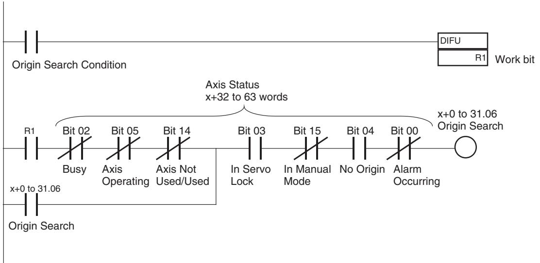
Program Example 1: Origin Search Using an Incremental Encoder
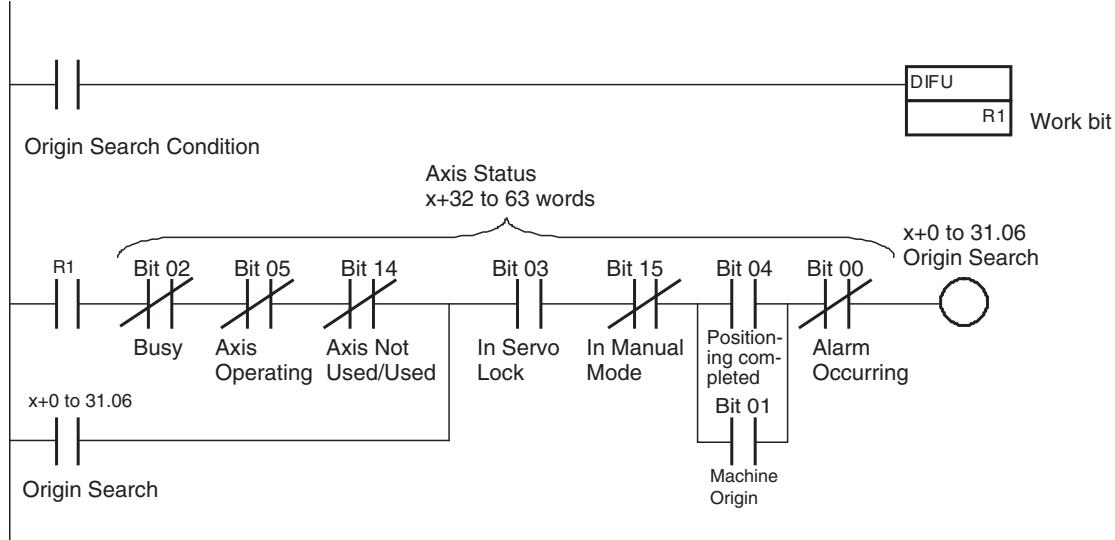
Program Example 2: Origin Search Using an Absolute Encoder
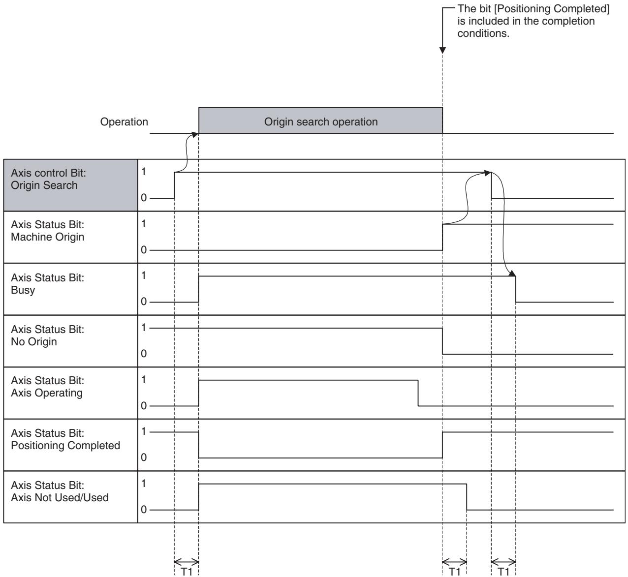
Timing Chart
Basic Operation:
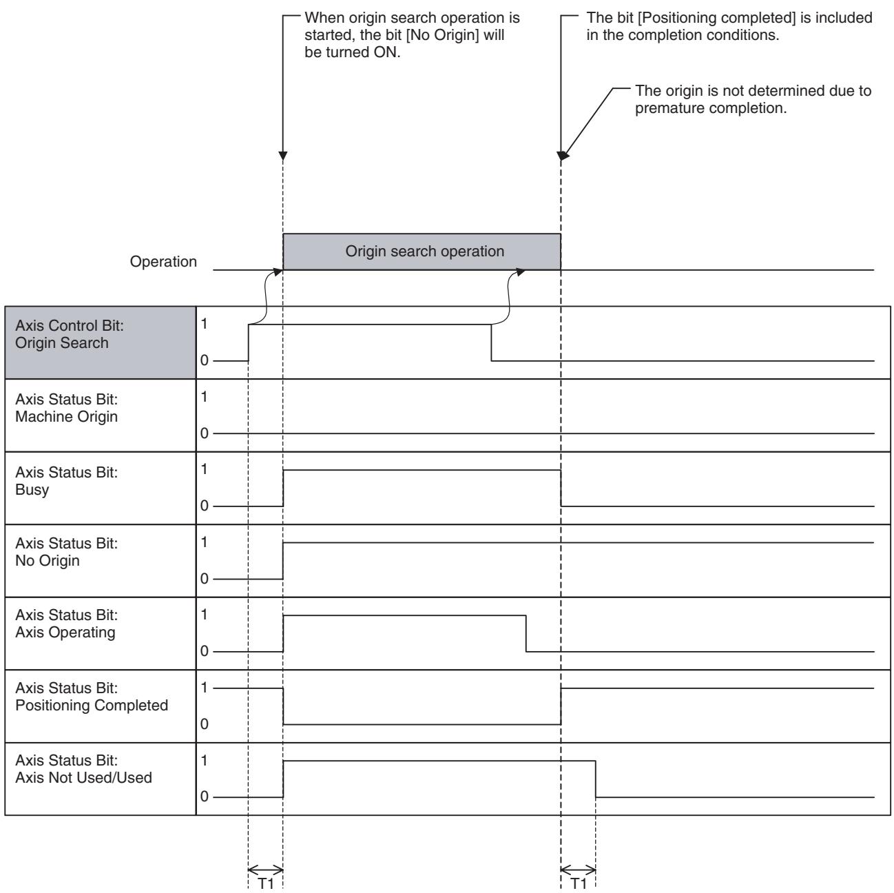
Premature completion:
| Word | Variable | Bit | Name | I/O |
| x+0 | IW0440 | 07 | Machine Origin Return (Axis 1) | Output |
| - | - | - | ||
| x+31 | IW045F | Machine Origin Return (Axis 32) |
Function
- With the bit [Machine Origin Return], positioning to the machine origin that has been determined is executed.
- The axis Automatically will decelerate to stop when the bit [Machine Origin] is detected.
- [Axis Override] is applied to the speed. For details on timing, etc., see Relation between Task Override and Axis Override (page 462).
Command and Operation
| Name | Specifications |
| Machine Origin Return | 0: Nil1: Continues Machine origin return (PTP)↑: Starts Machine origin return (PTP)↓: Stops Machine origin return (PTP) |
The machine origin return operation will be started when the bit [Machine Origin Return] is turned ON. Even if the axis has not reached the machine origin, it decelerates to stop when the bit is turned OFF.
Status Condition
| Name | Specifications |
| Machine Origin | 0: Machine coordinate system FB position is outside of origin in-position range. 1: Machine coordinate system FB position is within origin in-position range. |
| Busy | 0: Not executing any of the functions listed below. 1: Executing one of the functions listed below, or the command bit is ON. JOG, STEP, Origin Search, Machine Origin Return, Error Counter Reset, Forced Origin, and ABS Origin Setting |
| No Origin | 0: Origin on machine coordinate system is defined. 1: Origin on machine coordinate system is not defined. |
| Axis Operating | 0: No axis operating command 1: Axis operating command being output. |
| Positioning Com-pleted | 0: Outputting positioning command, or axis is outside of in-position range. 1: Not outputting positioning command, and axis is within in-position range. |
| Axis Not Used/Used | 0: Axis is not being used. 1: Axis is being used. (In Manual Mode: Axis is used for JOG etc., In Automatic Mode: Axis is declared in the operating program) |
Effect of Other Functions
| Classification | Item | Effect |
| Physical Status | Servo Axis | No effect |
| Virtual Axis | No effect | |
| I/O Axis | Ignored | |
| Counter Axis | Ignored | |
| Status Bits | Busy | Machine origin return cannot be executed when ON. |
| In Servo Lock | Machine origin return cannot be executed when OFF. | |
| No Origin | Machine origin return cannot be executed when ON. | |
| Axis Operating | Machine origin return cannot be executed when ON. | |
| Positioning Completed | Being ON is included in the completion conditions. | |
| Positioning Completed (No.2) | No effect | |
| Axis Machine Lock Status | No effect | |
| Command Disabled/Enabled | Machine origin return cannot be executed when OFF. | |
| Axis Not Used/Used | Machine origin return cannot be executed when ON. | |
| In Manual/Automatic Mode | Machine origin return cannot be executed when ON. |
Effect on Other Functions
Nil
System Parameter
The following system parameters determine the speed pattern:
| Parameter No. | Name |
| P2AA02 | Maximum manual feed rate |
| P2AA04 | Manual feed rate |
| P2AA07 | Manual feed acceleration time |
| P2AA08 | Manual feed deceleration time |
Program Example
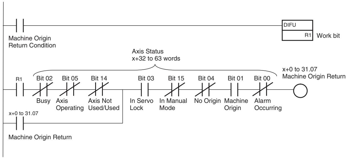
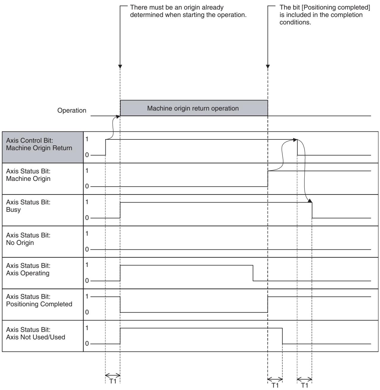
Timing Chart
Basic operation:
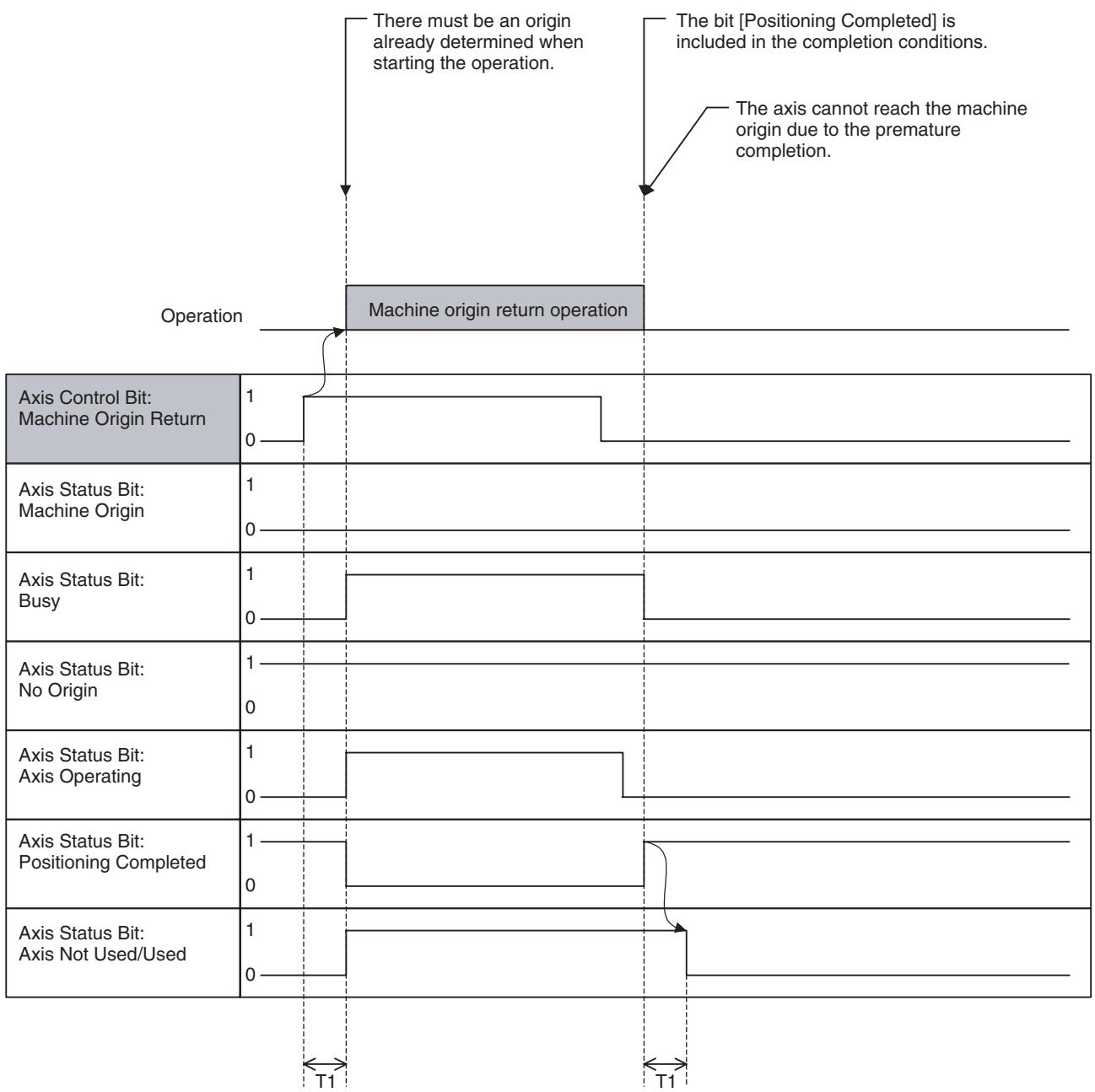
Premature completion:
| Word | Variable | Bit | Name | I/O |
| x+0 | IW0440 | 08 | Error Counter Reset (Axis 1) | Output |
| - | - | - | ||
| x+31 | IW045F | Error Counter Reset (Axis 32) |
Function
The error counter pulses that accumulated in a pressing operation, etc. using position control and torque control are forcibly cleared to put the axis into the positioning completed state.
Command and Operation
| Name | Specifications |
| Error Counter Reset | 0: Nil1: Nil↑: Resets error counter↓: Interrupts Error counter reset |
- When the bit [In Servo Lock] is OFF:
The error counter reset processing will be executed when the bit [Error Counter Reset] is turned ON.
Note Actually, Errors are not generated.
When the bit [Axis Operating] is OFF:
- The error counter reset processing will be executed when the bit [Error Counter Reset] is turned ON.
- When the bit [Axis Operating] is ON:
When the bit [Axis Operating] is turned OFF after the rising edge of the bit [Error Counter Reset], the error counter reset processing will be executed. If the bit [Error Counter Reset] has been turned OFF before the bit [Axis Operating] is turned OFF, the error counter reset processing will not be executed.
Note
If the MC Unit and MECHATROLINK-II Servo are used together, the position loop is managed on the MECHATROLINK-II Servo. Therefore, depending on error amount, the error counter reset processing may not be executed at once, but may be executed being divided into several communication scans. In this case, the processing to output a position command that resets the error counter to the MECHATROLINK-II Servo is called the "Error counter reset".
Status Condition
| Name | Specifications |
| Busy | 0: Not executing any of the functions listed below.1: Executing one of the functions listed below, or the command bit is ON.JOG, STEP, Origin Search, Machine Origin Return, Error Counter Reset, Forced Origin, and ABS Origin Setting |
Effect of Other Functions Effect on Other Functions
Error counter reset cannot be executed while the bit [Axis Operating] is ON.
| Classification | Item | Effect |
| Physical Status | Servo Axis | No effect |
| Virtual Axis | No effect (Errors are not generated.) | |
| I/O Axis | Ignored | |
| Counter Axis | Ignored | |
| Status Bits | Busy | No effect |
| In Servo Lock | No effect | |
| No Origin | No effect | |
| Axis Operating | Error counter reset cannot be executed when ON (wait until turned OFF). | |
| Positioning Completed | No effect | |
| Positioning Completed (No. 2) | No effect | |
| Axis Machine Lock Status | No effect | |
| Command Disabled/Enabled | Error counter reset cannot be executed when OFF. | |
| Axis Not Used/Used | No effect | |
| In Manual/Automatic Mode | No effect |
System Parameter
Nil
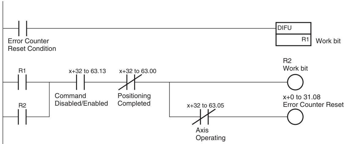
Program Example
Timing Chart
Basic operation 1 (The bit [Error Counter Reset] is turned OFF after checking the bit [Positioning Completed].):
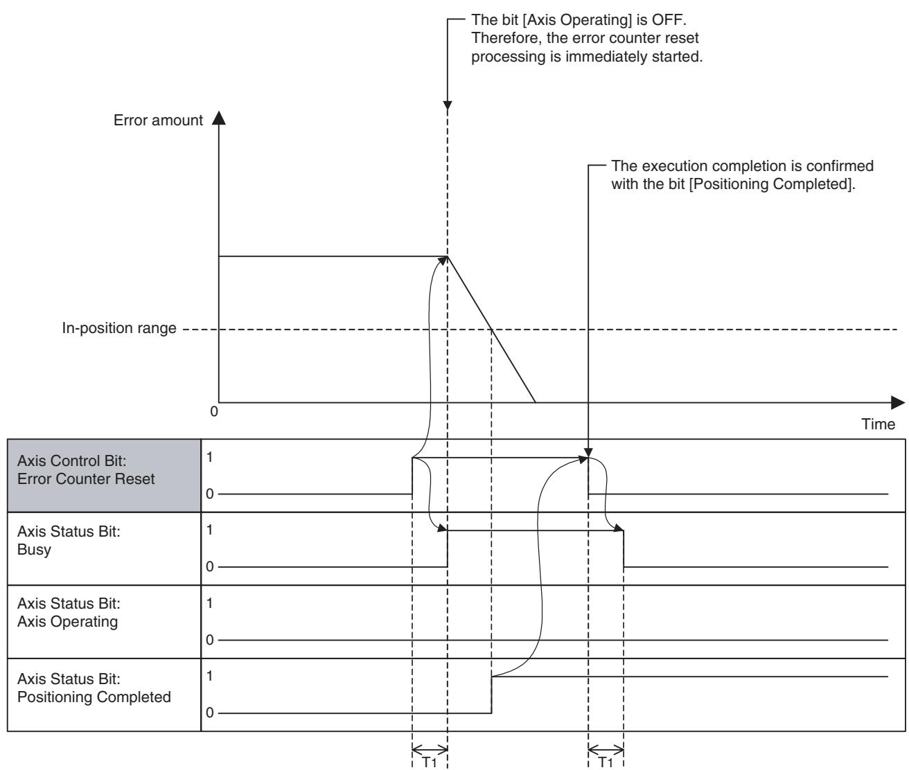
Basic operation 2 (The bit [Error Counter Reset] is turned OFF without checking the bit [Positioning Completed].):
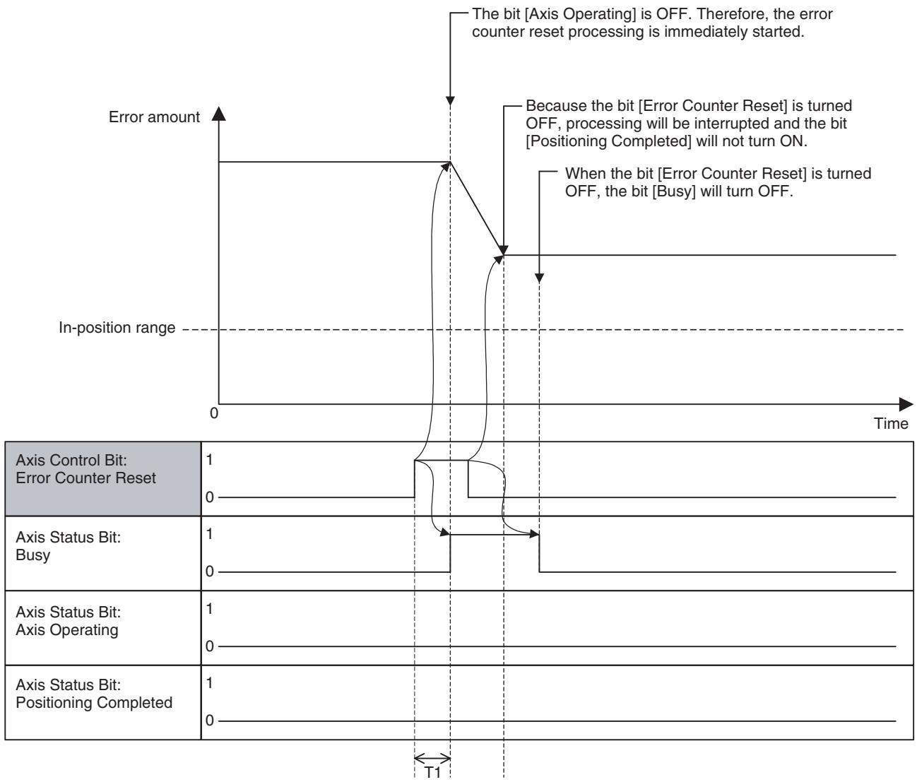
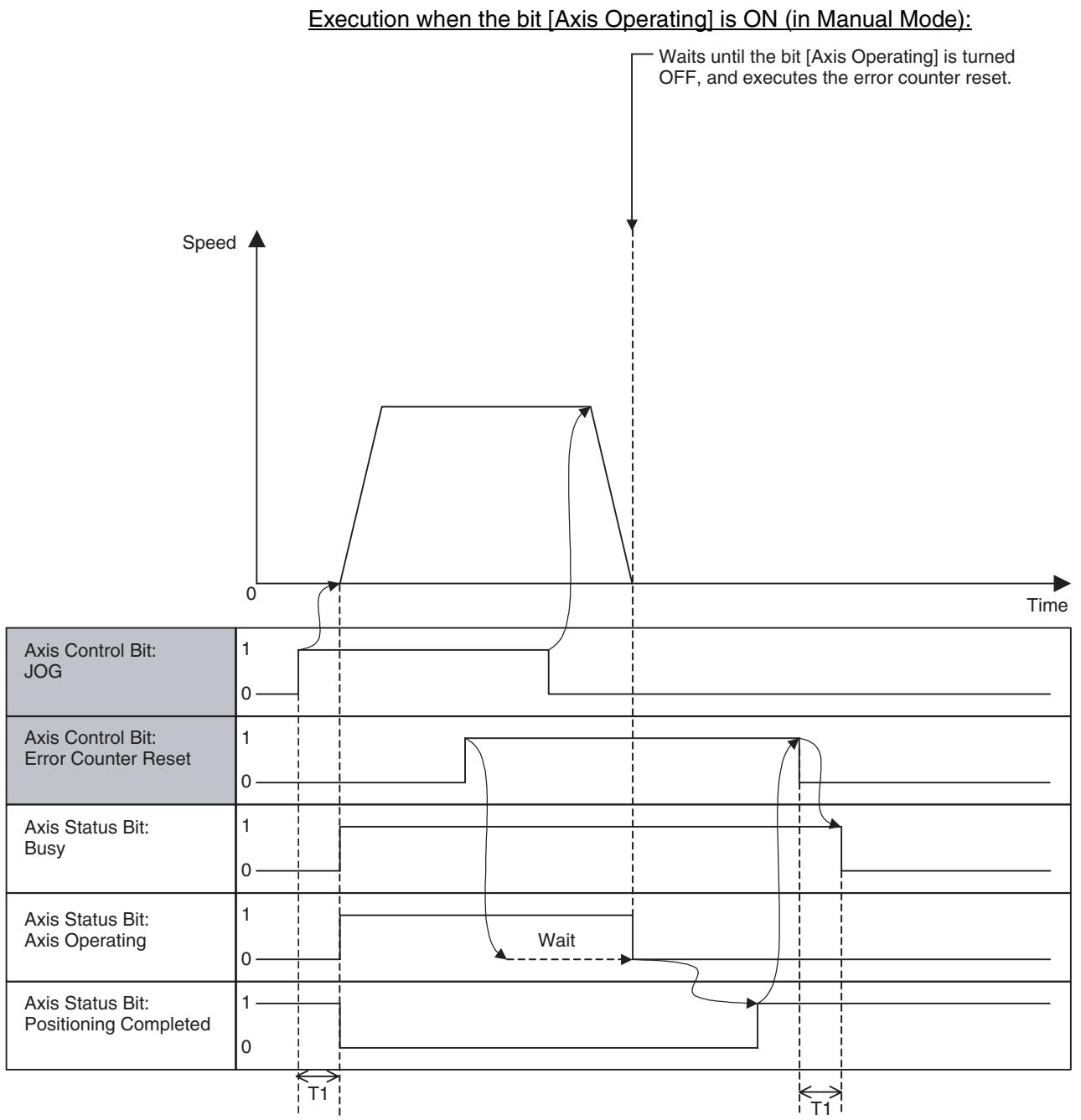
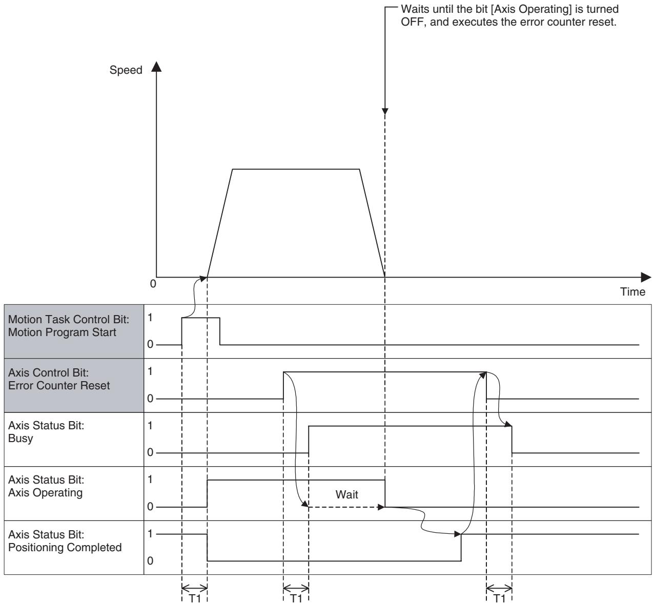
Execution when the bit [Axis Operating] is ON (in Automatic Mode):
| Word | Variable | Bit | Name | I/O |
| x+0 | IW0440 | 09 | Forced Origin (Axis 1) | Output |
| - | - | - | ||
| x+31 | IW045F | Forced Origin (Axis 32) |
Function
With this bit, the present position is defined as the machine origin.
Command and Operation
| Name | Specifications |
| Forced Origin | 0: Nil1: Nil↑: The present position is defined as the origin on the machine coordinate system (disabled during operation).↓: Nil |
The machine origin will be defined when the bit [Forced Origin] is turned ON.
Status Condition
| Name | Specifications |
| Machine Origin | 0: Machine coordinate system FB position is outside of origin in-position range. 1: Machine coordinate system FB position is within origin in-position range. |
| Busy | 0: Not executing any of the functions listed below. 1: Executing one of the functions listed below, or the command bit is ON. JOG, STEP, Origin Search, Machine Origin Return, Error Counter Reset, Forced Origin, and ABS Origin Setting |
| No Origin | 0: Origin on machine coordinate system is defined. 1: Origin on machine coordinate system is not defined. |
| Axis Operating | 0: No axis operating command 1: Axis operating command being output. |
| Positioning Com-pleted | 0: Outputting positioning command, or axis is outside of in-position range. 1: Not outputting positioning command, and axis is within in-position range. |
Effect of Other Functions
| Classification | Item | Effect |
| Physical Status | Servo Axis | No effect |
| Virtual Axis | No effect | |
| I/O Axis | Ignored | |
| Counter Axis | Ignored | |
| Status Bits | Busy | Forced origin cannot be executed when ON. |
| In Servo Lock | No effect | |
| No Origin | No effect | |
| Axis Operating | Forced origin cannot be executed when ON. | |
| Positioning Completed | Forced origin cannot be executed when OFF. | |
| Positioning Completed (No.2) | No effect | |
| Axis Machine Lock Status | No effect | |
| Command Disabled/Enabled | Forced origin cannot be executed when OFF. | |
| Axis Not Used/Used | Forced origin cannot be executed when ON. | |
| In Manual/Automatic Mode | Forced origin cannot be executed when ON. |
Effect on Other Functions
Nil
System Parameter
The following parameter determines the position after defining the machine origin:
| Parameter No. | Name | Remark |
| P4AA10 | Reference (machine) ori-gin offset | The position after forced origin execu-tion will be the one that is specified in this parameter. |
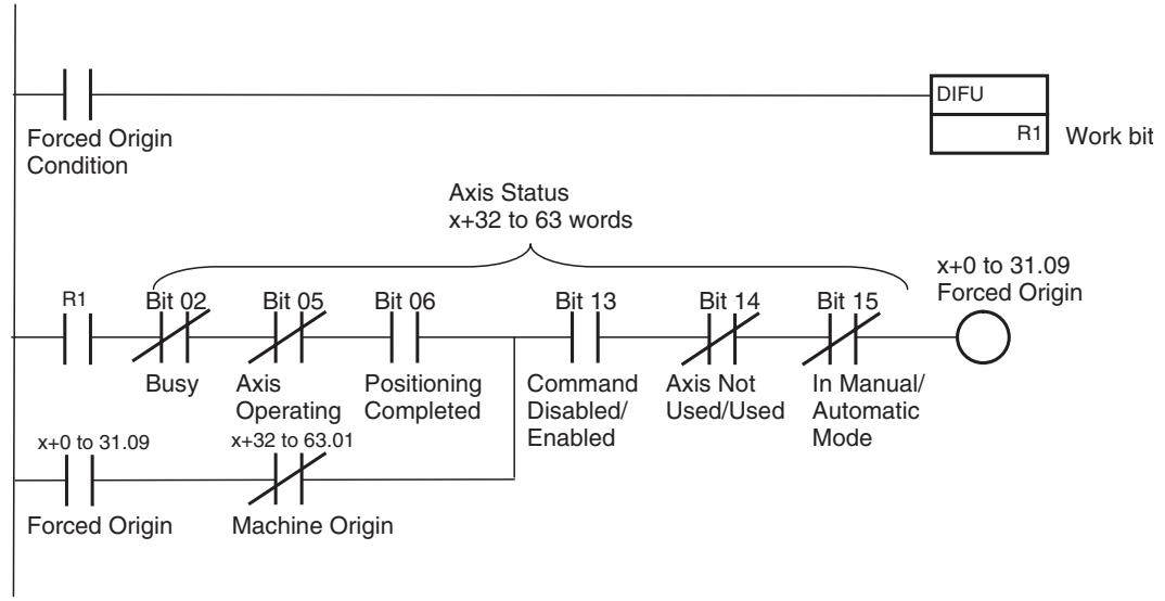
Program Example
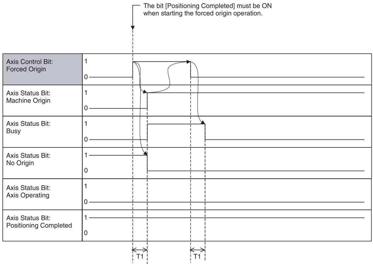
Timing Chart
Basic operation:
| Word | Variable | Bit | Name | I/O |
| x+0 | IW0440 | 10 | ABS Origin Setting (Axis 1) | Output |
| - | - | - | ||
| x+31 | IW045F | ABS Origin Setting (Axis 32) |
Function
The present position will be defined as the machine origin when the bit [ABS Origin Setting] is turned ON and the positional relation between the origin and ABS encoder value is saved into the flash ROM. With this function, the need for origin searches when switching ON the ABS encoder will be eliminated.
Command and Operation
| Name | Specifications |
| ABS Origin Setting | 0: Nil1: Nil↑: Sets ABS encoder origin.↓: Nil |
Status Condition
| Name | Specifications |
| Machine Origin | 0: Machine coordinate system FB position is outside of origin in-position range. 1: Machine coordinate system FB position is within origin in-position range. |
| Busy | 0: Not executing any of the functions listed below. 1: Executing one of the functions listed below, or the command bit is ON. JOG, STEP, Origin Search, Machine Origin Return, Error Counter Reset, Forced Origin, and ABS Origin Setting |
| No Origin | 0: Origin on machine coordinate system is defined. 1: Origin on machine coordinate system is not defined. |
| Axis Operating | 0: No axis operating command 1: Axis operating command being output. |
| Positioning Com-pleted | 0: Outputting positioning command, or axis is outside of in-position range. 1: Not outputting positioning command, and axis is within in-position range. |
Effect of Other Functions
| Classification | Item | Effect |
| Physical Status | Servo Axis | • ABS origin setting can be executed only on the ABS encoder axis. • If ABS origin setting is executed on the INC encoder axis, the positional relation between the origin and ABS encoder value will be cleared. |
| Virtual Axis | Ignored | |
| I/O Axis | Ignored | |
| Counter Axis | Ignored | |
| Status Bits | Busy | ABS origin setting cannot be executed when ON. |
| In Servo Lock | No effect | |
| No Origin | No effect | |
| Axis Operating | ABS origin setting cannot be executed when ON. | |
| Positioning Completed | ABS origin setting cannot be executed when OFF. | |
| Positioning Completed (No.2) | No effect | |
| Axis Machine Lock Status | No effect | |
| Command Disabled/Enabled | ABS origin setting cannot be executed when OFF. | |
| Axis Not Used/Used | ABS origin setting cannot be executed when ON. | |
| In Manual/Automatic Mode | ABS origin setting cannot be executed when ON. |
Effect of Other Function
System Parameter
Nil
The following system parameter determines the position after ABS origin setting:
| Parameter No. | Name | Remark |
| P4AA12 | ABS origin offset | The position after ABS origin setting will be the one that is specified in this parameter. |
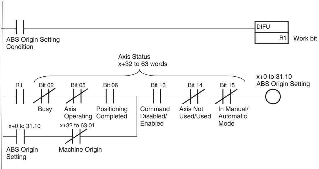
Program Example
Timing Chart
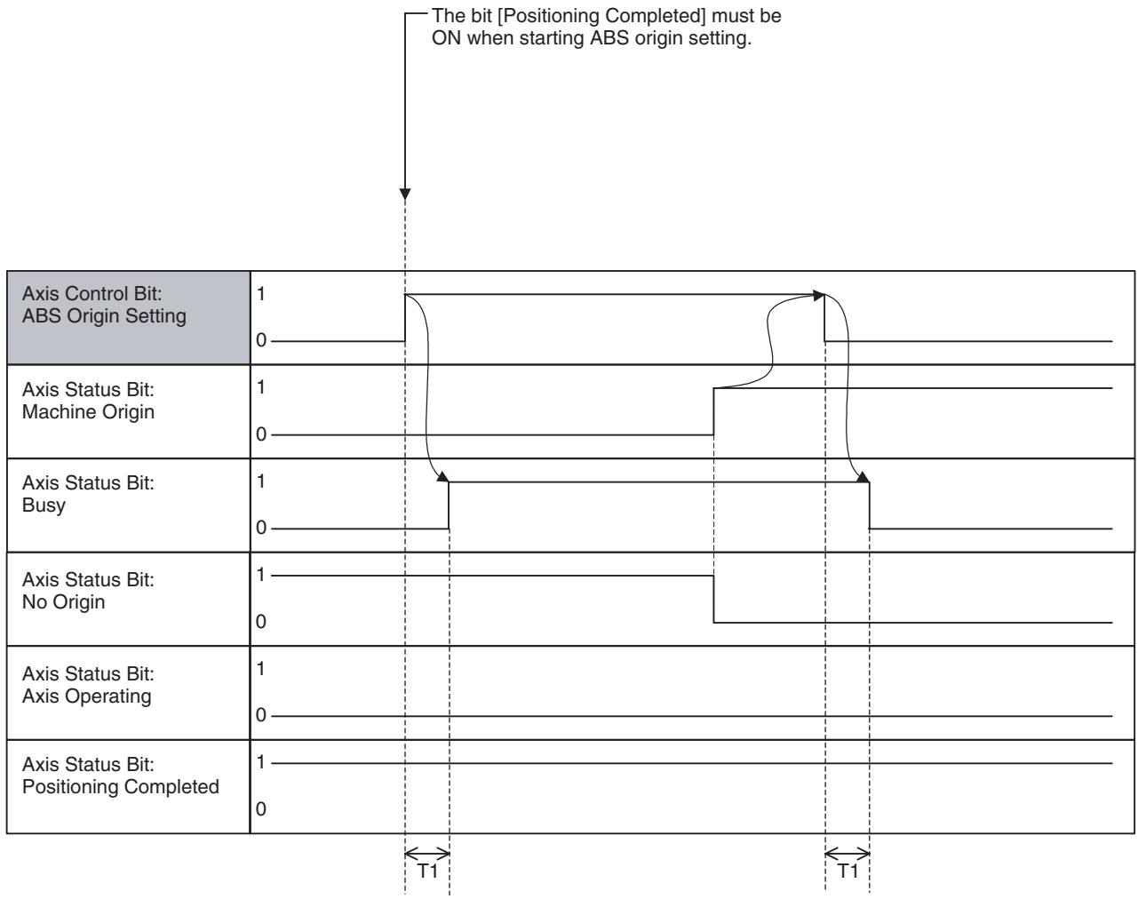
| Word | Variable | Bit | Name | I/O |
| x+0 | IW0440 | 11 | Axis Override Enable (Axis 1) | Output |
| - | - | - | ||
| x+31 | IW045F | Axis Override Enable (Axis 32) |
Function
- Override is the function to change the feed rate specified in the motion program or parameter to the user-specified speed with % specification.
- There are three types of override, the task override, axis override, and internal override. They are used differently in motion program execution depending on the speed.
-
The axis override can be applied to the speed specified by operand V in the motion program or the speed set in the axis parameter.
-
The relations between each command and override are shown in the table below:
| Classification | Function/Name | Command | Override | Remark |
| Axis Movement | Positioning | MOVE | Axis Override Internal Over-ride | |
| Linear Interpolation | MOVEL | Task Override | ||
| Circular Interpolation | MOVEC | Task Override | ||
| Origin Search | DATUM | Axis Override | Applicable only for origin search feed rate | |
| Interrupt Feeding | MOVEI | Axis Override Internal Over-ride | ||
| Time-specified Positioning | MOVET | Axis Override Internal Over-ride | Specified time period cannot be kept. | |
| Traverse | MOVETRAV | Task Override | ||
| Electronic Cam, Single Axis | CAM | Disable | ||
| Axis Operation | Link Operation | MOVELINK | Disable | |
| Electronic Cam, Synchronous | CAMBOX | Disable | ||
| Electronic Shaft | CONNECT | Disable | ||
| Trailing Synchronization | SYNC | Disable | ||
| Travel Distance Superimpose | ADDAX | Disable | ||
| Speed Control | SPEED | Disable | ||
| Torque Control | TORQUE | Disable | ||
| Axis Operation Cancel | Trailing Synchronization Can-cel | SYNCR | Disable | |
| Travel Distance Superimpose Cancel | ADDAXR | Disable | ||
| Speed Control Cancel | SPEEDDR | Disable | ||
| Torque Control Cancel | TORQUER | Disable |
Command and Operation
| Name | Specifications |
| Axis Override Enable | 0: Enables axis override value (override 100% is used.)1: Enables axis override value↑: Nil↓: Nil |
| Axis Override | 0 to 32767 [0.01%]0.00% if value out of range is input. |
- The value in [Axis Override] is enabled only while the bit [Axis Override Enable] is turned ON. When the bit is OFF, override 100.00% is used.
- The bit [Axis Override Enable] and data [Axis Override] are always referenced.
Status Condition Nil
Effect of Other Functions Nil
Effect on Other Functions Speed of the functions with axis movement is affected.
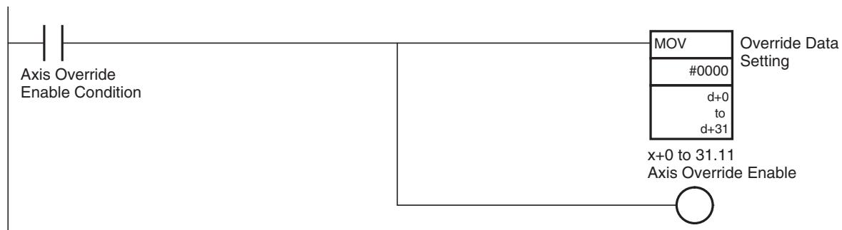
Program Example
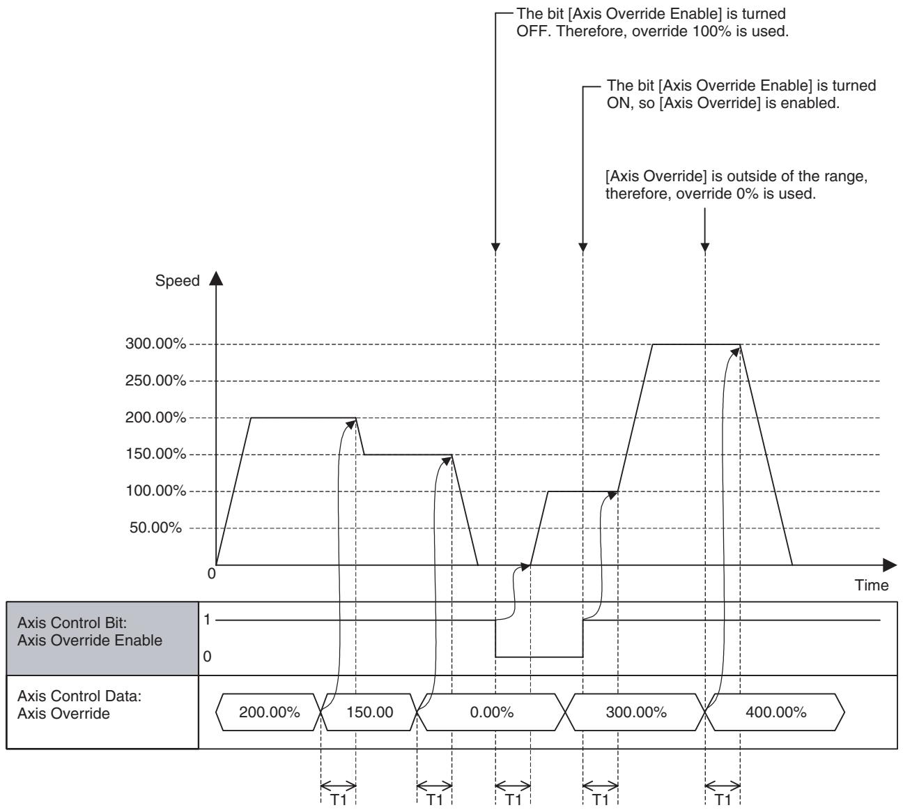
Timing Chart
Basic Operation:
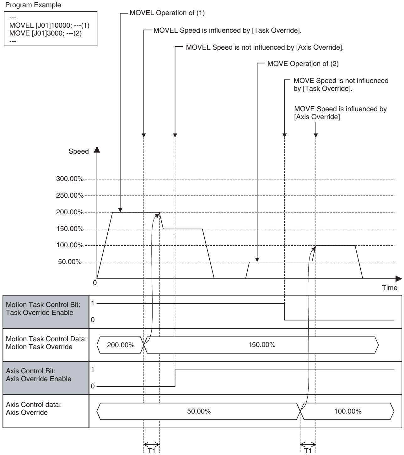
Relation between Task Override and Axis Override:
| Word | Variable | Bit | Name | I/O |
| x+0 | IW0440 | 13 | Axis Machine Lock (Axis 1) | Output |
| - | - | - | ||
| x+31 | IW045F | Axis Machine Lock (Axis 32) |
Function
- With Axis machine lock, output for axis movement is stopped to debug the sequences other than the ones for the axis movement.
-
Even though command output for axis is stopped, the command position will be updated and signal for the output modules will be output normally.
-
When Axis machine lock status is cancelled, the command position returns to the position (Feedback present position) before the machine lock status.
- The Axis machine Lock function works on each axis independently. Therefore, make sure to take caution when the operation (interpolation, etc.) involves multiple axes.
- Even under Axis machine lock state, Servo Lock is required to use functions with axis movement.
Command and Operation
| Name | Specifications |
| Axis Machine Lock | 0: Not using Axis machine lock mode1: Using Axis machine lock mode↑: No↓: No |
Status Condition
| Name | Function |
| Axis Operating | 0: No axis operating command 1: Axis operating command being output. |
| Positioning Com-pleted | 0: Outputting positioning command, or axis is outside of in-position range. 1: Not outputting positioning command, and axis is within in-position range. |
| Axis Machine Lock Status | 0: Not in Axis machine lock mode 1: In Axis machine lock mode |
| Axis Not Used/Used | 0: Axis is not being used. 1: Axis is being used. (In Manual Mode: Axis is used for JOG etc., In Automatic Mode: Axis is declared in the operating program) |
Status of the bit [Axis Machine Lock] is reflected in the bit [Axis Machine Lock Status].
Effect of Other Functions
| Classification | Item | Effect |
| Physical Status | Servo Axis | No effect |
| Virtual Axis | Ignored | |
| I/O Axis | Ignored | |
| Counter Axis | Ignored | |
| Control Status | In Position control | No effect |
| In Speed control | Output for Speed command not stopped | |
| In Torque control | Output for Torque command not stopped | |
| Status Bits | Busy | No effect |
| In Servo Lock | No effect | |
| No Origin | No effect | |
| Axis Operating | Axis machine lock state will not be changed when ON. | |
| Positioning Completed | No effect | |
| Positioning Completed (No.2) | No effect | |
| Axis Machine Lock Status | No effect | |
| Command Disabled/Enabled | Axis machine lock state is cancelled when OFF. | |
| Axis Not Used/Used | No effect | |
| In Manual/Automatic Mode | No effect |
Effect on Other Functions
In Axis machine lock state, the origin search operations (with DATUM command, Axis Control Bit: Origin Search) will be executed in the same way as the operations with the Axis Control Bit [Forced Origin].
System Parameter
Nil
Program Example
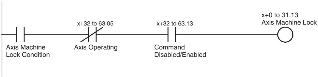
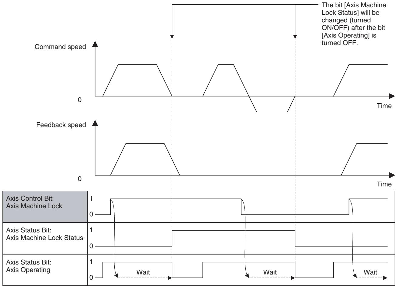
Timing Chart
Basic Operation:
Operation in Speed or Torque Control:
In Speed or Toque Control, it is not guaranteed that the axis will not move when the command output is stopped. Therefore, the bit [Axis Machine Lock Status] is not changed (turned ON/OFF). Due to the same reason, while the bit [Axis Machine Lock Status] is 1 (ON), commands are output not as Speed or Torque command, but as Position command.
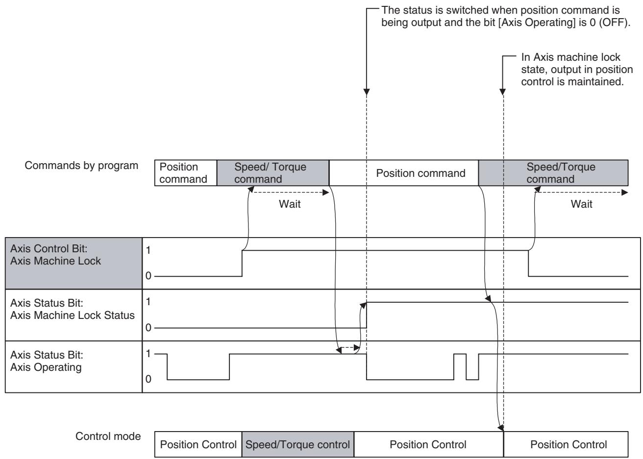
| Word | Variable | Bit | Name | I/O |
| x+0 | IW0440 | 15 | Manual/Automatic Mode (Axis 1) | Output |
| - | - | - | ||
| x+31 | IW045F | Manual/Automatic Mode (Axis 32) |
Function
With this bit, the operating mode of the axis is switched.
Command and Operation
| Name | Specifications |
| Manual/Automatic Mode | 0: In Manual Mode1: In Automatic Mode↑: Decelerates to stop the manual operation being executed↓: Decelerates to stop the automatic operation being executed |
Status Condition
| Name | Specifications |
| Busy | 0: Not executing any of the functions listed below.1: Executing one of the functions listed below, or the command bit is ON.JOG, STEP, Origin Search, Machine Origin Return, Error Counter Reset, Forced Origin, and ABS Origin Setting |
| Axis Not Used/Used | 0: Axis is not being used.1: Axis is being used.(In Manual Mode: Axis is used for JOG etc., In Automatic Mode: Axis is declared in the operating program) |
| In Manual/Automatic Mode | 0: In Manual Mode (JOG, STEP, and Origin Search can be executed.)1: In Automatic Mode (Motion programs can be executed.) |
Effect of Other Functions
The operating mode status is output to the bit [In Manual/Automatic Mode].
Conditions for each Axis Status Bit are as shown below:
| Name | Condition |
| Busy | ·Does not turn ON ·The bit [Manual/Automatic Mode] can be changed (ON/OFF) in Busy state. |
| Servo Lock | ·No effect |
| No Origin | ·The bit [Manual/Automatic Mode] can be changed regardless of whether the origin for the machine coordinate system has been defined or not. |
| Axis Operating | ·Does not turn ON |
| Positioning Completed | ·The bit [Manual/Automatic Mode] cannot be changed when OFF. |
| Axis Machine Lock Status | ·No effect |
| Command Disabled/Enabled | ·The bit [Manual/Automatic Mode] cannot be changed when OFF. |
| Axis Not Used/Used | ·Does not turn ON |
| In Manual/Automatic Mode | ·No effect |
Effect on Other Functions
The functions on each axis are limited depending on ON/OFF of the bit [In Manual/Automatic Mode] as shown below:
| Function | In Manual/Automatic Mode | |
| OFF (Manual) | ON (Automatic) | |
| Axis Control Bit: Axis Alarm Reset | Can be executed | Can be executed |
| Axis Control Bit: Deceleration Stop | Can be executed | Cannot be executed |
| Axis Control Bit: Servo Lock | Can be executed | Can be executed |
| Axis Control Bit: Servo Unlock | Can be executed | Can be executed |
| Axis Control Bit: JOG | Can be executed | Cannot be executed |
| Axis Control Bit: STEP | Can be executed | Cannot be executed |
| Axis Control Bit: Origin Search | Can be executed | Cannot be executed |
| Axis Control Bit: Machine Origin Return | Can be executed | Cannot be executed |
| Axis Control Bit: Error Counter Reset | Can be executed | Can be executed |
| Axis Control Bit: Forced Origin | Can be executed | Cannot be executed |
| Axis Control Bit: ABS Origin Setting | Can be executed | Cannot be executed |
| Axis Control Bit: Axis Override Enable | Can be executed | Can be executed |
| Axis Control Bit: JOG/STEP Direction | Can be executed | Cannot be executed |
| Axis Control Bit: Axis Machine Lock | Can be executed | Can be executed |
| Axis Control Bit: Manual/Automatic Mode | Can be executed | Can be executed |
| IOWR: Present Position Preset | Can be executed | Cannot be executed |
- When the bit [Manual/Automatic Mode] is turned ON (1) during a manual operation, the manual operation being executed will be interrupted by deceleration stop. The bit [In Manual/Automatic Mode] will be turned ON when the bit [Axis Not Used/Used] is turned OFF after the interruption.
- If the bit [Manual/Automatic Mode] for the axis declared by PROG command in the motion program is turned OFF (0) during an automatic operation, the program operation being executed will be interrupted by deceleration stop. The status bit [In Manual/Automatic Mode] will be turned OFF when the bit [Axis Not Used/Used] is turned OFF after the interruption.
- If the bit [In Manual/Automatic Mode] for the axis declared by PROG command is OFF (0) when starting a motion program, the bit [Start Warning] will be turned ON and the motion program cannot be executed.
System Parameter
Nil
Program Example
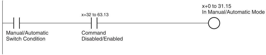
Timing chart
Basic Operation:
| Axis Control Bit: Manual/Automatic Mode | 1 0 | ||
| Axis Status Bit: In Manual/Automatic Mode | 1 0 | ||
| ←T1 | →T1 |
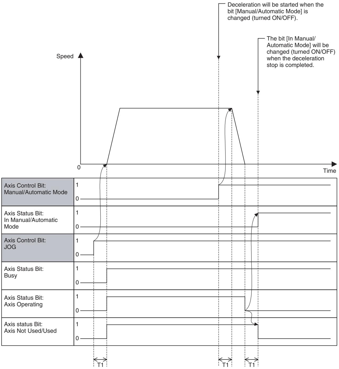
Axis operation switch in Manual Mode:
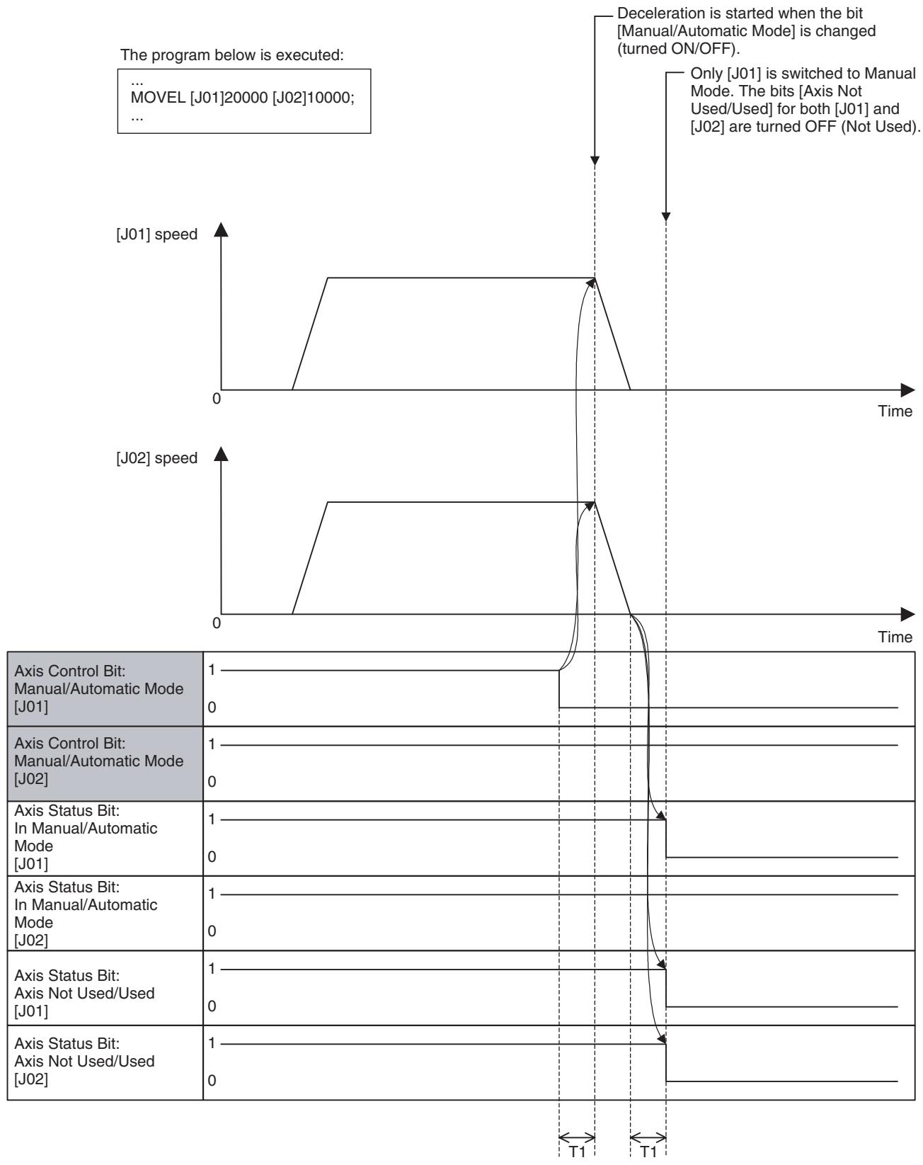
Switch during program operation in Automatic Mode:
| Word | Variable | Bit | Name | I/O |
| x+0 | IW0440 | 00 | Axis Alarm Reset (Axis 1) | Output |
| -x+31 | IW045F | Axis Alarm Reset (Axis 32) | ||
| x+32 | OW0440 | 00 | Axis Alarm Occurring (Axis 1) | Input |
| -x+63 | OW045F | Axis Alarm Occurring (Axis 32) |
Function
- When an error that requires stopping the operation occurs in the MC Unit or MECHATROLINK-II slaves, it will be detected as an alarm.
- Executing alarm reset after removing the cause can clear alarms (except for some alarms).
- When communications are disconnected during normal operations, the bit [Axis Alarm Reset] will be turned ON to make the concerned axis usable again.
Command and Operation
| Name | Specifications |
| Axis Alarm Reset | 0: Nil1: Does not turn ON the bit [Axis Alarm Occurring]↑: Clears alarm occurring on axis level and warning on ML-10.↓: Nil |
Alarms on the axis or MECHATROLINK-II slave level will be reset when the bit [Axis Alarm Reset] is turned ON.
| Name | Specifications |
| Axis Alarm Occur-ring | 0: Alarm not occurring on axis or MECHATROLINK-II slave.1: Alarm occurring on axis or MECHATROLINK-II slave. |
Status Condition
| Name | Specifications |
| Alarm Occurring | 0: No alarm 1: Alarm occurring on MC Unit (linked to ERC indicator) |
| Axis Alarm Occurring 1-16 | 0: No alarm occurring on axis or the bit [Axis Alarm Reset] is ON 1: Alarm occurring on axis |
| Axis Alarm Occurring 17-32 | 0: No alarm occurring on axis or the bit [Axis Alarm Reset] is ON 1: Alarm occurring on axis |
| Axis Alarm | 0: No alarm occurring on axis or MECHATROLINK-II slave 1: Alarm occurring on axis or MECHATROLINK-II slave |
| Axis Alarm Code | Outputs the code of the alarm occurring on axis |
- If an alarm occurs on an axis or MECHATROLINK-II slave, the bits [Alarm Occurring], [Axis Alarm Occurring 1-32], and [Axis Alarm] will be turned ON, and the alarm code (3013h) will be stored in [Axis Alarm Code]. Detailed slave alarm codes are stored in the error log.
- When several alarms occur at the same time, the code of the alarm that was detected first will be stored in [Axis Alarm Code].
Effect of Other Functions
Nil
Effect on Other Functions
When an alarm occurs, various functions will be affected (operation failure, operation interruption etc.).
System Parameter
Nil
Program Example
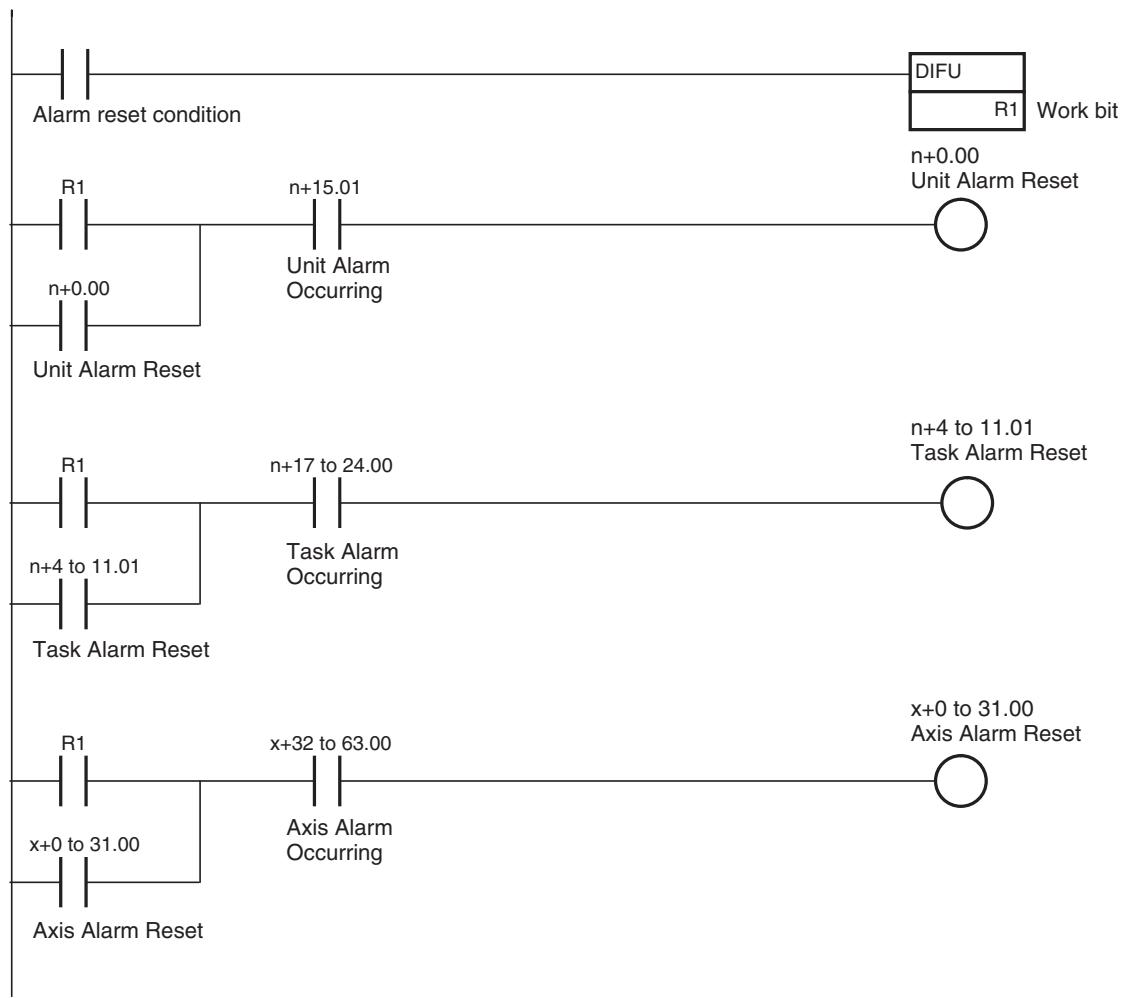
On MC Unit, there are three types of alarms:
Unit alarm
- Task alarm
- Axis alarm
Alarms are reset on the basis of each type. Therefore, execute the alarm reset over the Unit, Task, and Axis to clear an alarm occurring on the MC Unit without fail.
Timing Chart
Basic Operation (Alarm Occurring):
| Alarm identification Data: Alarm Occurring | 1 0 |
| Alarm identification Data: Axis Alarm Occurring | 1 0 |
| Axis Status Bit: Axis Alarm | 1 0 |
| Axis Status Data: Axis Alarm Code | 0XXXX |
| Internal Alarm Status | 1 0 |
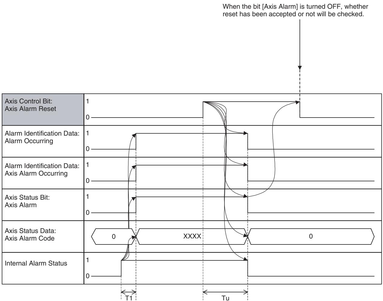
Basic Operation (Alarm Reset):
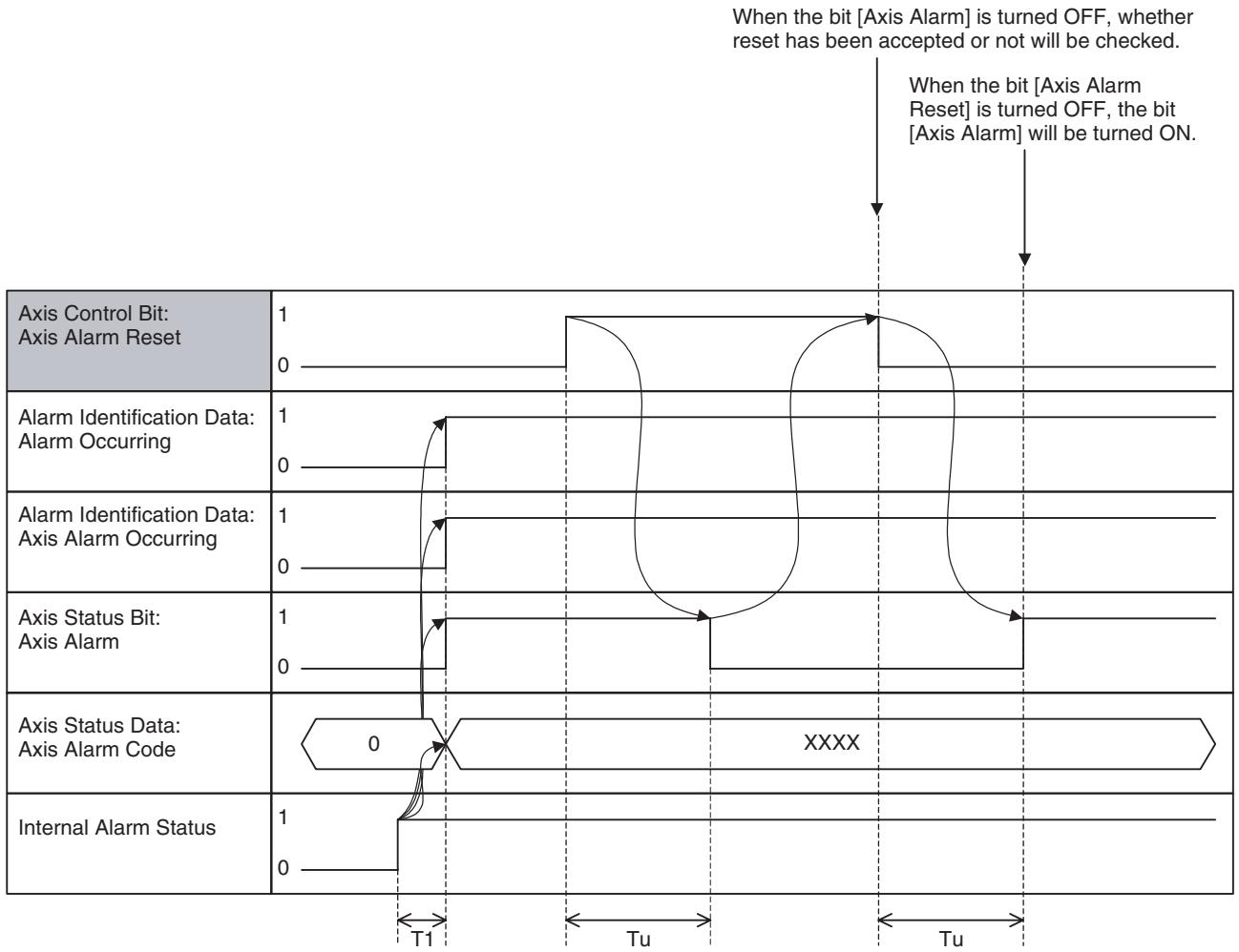
When an alarm that cannot be reset occurs:
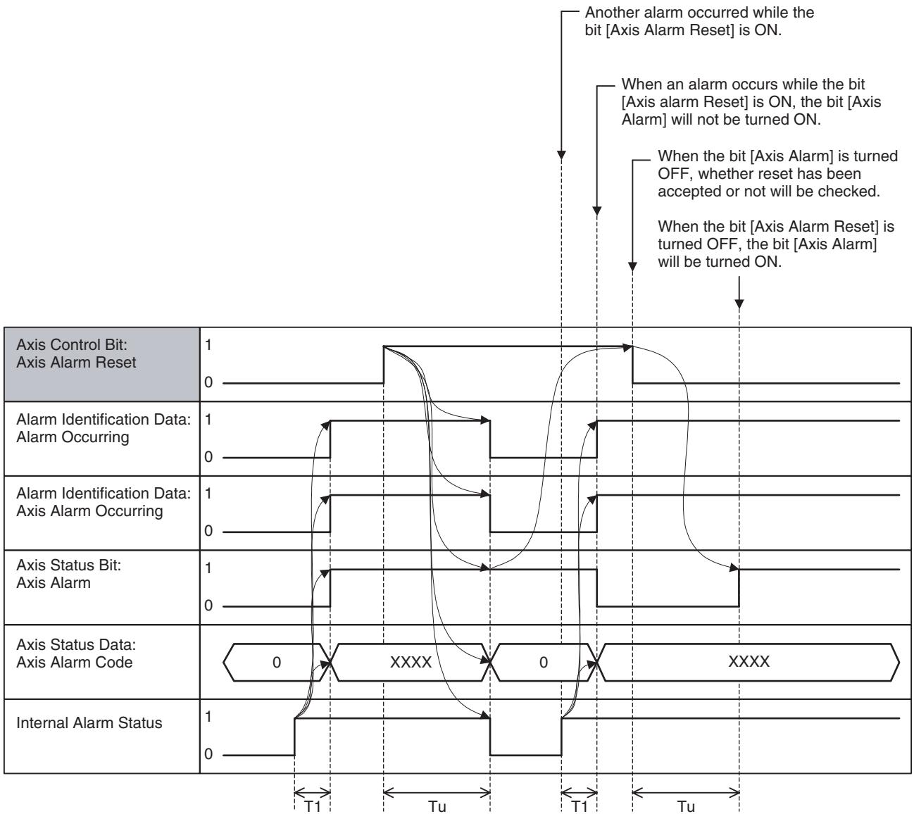
When an alarm occurs while the bit [Axis Alarm Reset] is ON:
| Word | Variable | Bit | Name | I/O |
| x+32 | OW0440 | 01 | Machine Origin (Axis 1) | Input |
| - | - | - | ||
| x+63 | OW045F | Machine Origin (Axis 32) |
Function
The bit [Machine Origin] indicates the status that the present position is located in the proximity of the origin on the machine coordinate system.
Status Condition
| Name | Specifications |
| Machine Origin | 0: Machine coordinate system FB position is outside of origin in-position range. 1: Machine coordinate system FB position is within origin in-position range. |
-
When the feedback position enters second in-position range (specified by the system parameter) of the machine origin, the bit [Machine Origin] is turned ON regardless of whether the origin has been defined or not.
-
1-shot output may occur. In that case, depending on the Scan Time of the ladder program and the Unit Scan Time of the MC Unit, the output may not be reflected in the ladder program.
Effect on Other Functions
The bit [Machine Origin] does not affect other functions directly. It can be used as the status to check the completion of the Axis Control Bit [Origin Search], [Machine Origin Return], or [DATUM command].
System Parameter
The range where the bit is turned ON/OFF is determined by the following system parameter:
| No. | Name |
| P3AA07 | No.2 In-position Range |
Timing Chart
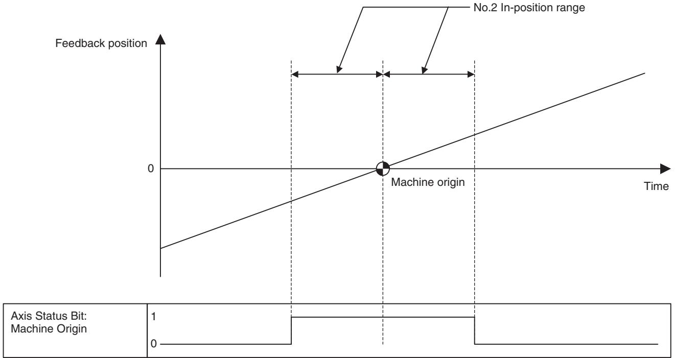
| Word | Variable | Bit | Name | I/O |
| x+32 | OW0440 | 02 | Busy (Axis 1) | Input |
| - | - | - | ||
| x+63 | OW045F | Busy (Axis 32) |
Function
The bit [Busy] indicates the status of the execution of each function on the axis level, and it is used to provide interlock among functions in the ladder program.
Status Function
| Name | Specifications |
| Busy | 0: Not executing any of the functions listed below.1: Executing one of the functions listed below, or the command bit is ON.JOG, STEP, Origin Search, Machine Origin Return, Error Counter Reset, Forced Origin, and ABS Origin Setting |
The bit [Busy] will be turned ON when the execution of the following functions is started after they were accepted, and turned OFF when the execution is completed and the command is turned OFF.
| Function |
| Axis Control Bit: JOG |
| Axis Control Bit: STEP |
| Axis Control Bit: Origin Search |
| Axis Control Bit: Machine Origin Return |
| Axis Control Bit: Error Counter Reset |
| Axis Control Bit: Forced Origin |
| Axis Control Bit: ABS Origin Setting |
Effect on Other Functions
The following functions will be restricted while the bit [Busy] is ON:
| Function | Restriction |
| Axis Control Bit: JOG | Cannot be executed |
| Axis Control Bit: STEP | Cannot be executed |
| Axis Control Bit: Origin Search | Cannot be executed |
| Axis Control Bit: Machine Origin Return | Cannot be executed |
| Axis Control Bit: Forced Origin | Cannot be executed |
| Axis Control Bit: ABS Origin Setting | Cannot be executed |
| Axis Control Bit: JOG/STEP Direction | Cannot be executed |
| IOWR: Present Position Preset | Cannot be executed |
System Parameter
Nil
Timing Chart
See "JOG Operation" (page 476), "STEP Operation" (page 480), "Origin Search" (page 484), "Machine Origin Return" (page 489), "Error Counter Reset" (page 493), "Forced Origin" (page 498), and "ABS Origin Setting" (page 500).
| Word | Variable | Bit | Name | I/O |
| x+32 | OW0440 | 04 | No Origin (Axis 1) | Input |
| - | - | - | ||
| x+63 | OW045F | No Origin (Axis 32) |
Function
The bit [No Origin] indicates the status of whether the origin on the machine coordinate system is defined or not.
Status Condition
| Name | Specifications |
| No Origin | 0: Origin on machine coordinate system is defined.1: Origin on machine coordinate system is not defined. |
- When the MC Unit is powered ON, the bit [No Origin] will be turned ON. It will be turned OFF through the operations of the following functions. Executing present position preset using IOWR will not turn OFF the bit.
| Function | Remark |
| Axis Control Bit: Origin Search | The bit [No Origin] will be turned OFF when Origin Search is completed normally. If the origin search method is “Origin at power ON”, the bit [No Origin] will be turned OFF simultaneously when the bit [Command Disabled/Enabled] is turned ON. |
| Axis Control Bit: Forced Origin | The bit [No Origin] will be turned OFF when Forced Origin is completed normally. |
| Axis Control Bit:ABS Origin Setting | The bit [No Origin] will be turned OFF when ABS Control Setting is completed normally.Subsequently, the bit will be turned OFF simultaneously when the bit [Command Disabled/Enable] is turned ON. |
| DATUM: Origin Search | The bit [No Origin] will be turned OFF when Origin Search is completed normally.If the origin search method is “Origin at power ON”, the bit [No Origin] will be turned OFF simultaneously when the bit [Command Disabled/Enable] is turned ON. |
| Virtual axis or ABS encoder axis with origin setting | Always OFF for Origin Search or any other functions |
-
Conditions for the bit [No Origin] to be turned ON in normal operations are as follows:
-
When an origin search is started (except for when the origin search method is "Origin at power ON").
- When the bit [Command Disabled/Enabled] is turned OFF.
Effect on Other Functions
When the bit [No Origin] is ON, the following functions will be restricted. Motion programs can be executed:
| Function | Restriction |
| Axis Control Bit: Machine Origin Return | Cannot be executed |
| Software Limit | Will not be enabled |
System Parameter
Nil
Timing Chart
See "Origin Search" (page 484), "Forced Origin" (page 498), and "ABS Origin Setting" (page 500).
| Word | Variable | Bit | Name | I/O |
| x+32 | OW0440 | 05 | Axis Operating (Axis 1) | Input |
| - | - | - | ||
| x+63 | OW045F | Axis Operating (Axis 32) |
Function
The bit [Axis Operating] indicates the status of the output of operation commands for the axis.
It turns ON even when no command is being output in Axis machine lock mode.
Status Condition
| Name | Specifications |
| Axis Operating | 0: No axis operating command 1: Axis operating command being output. |
- The bit [Axis Operating] changes its state (ON/OFF) for the operating commands in any one of Position, Speed, and Torque controls.
- 1-shot output may occur. In that case, depending on the Scan Time of the ladder program and the Unit Scan Time of the MC Unit, the output may not be reflected in the ladder program.
- The bit [Axis Operating] functions as the completion condition of the following axis operations:
Effect on Other Functions
| Function | Remark |
| Axis Control Bit: JOG | |
| Axis Control Bit: STEP | |
| MOVEL Command: Linear Interpolation | In Pass Mode |
| MOVEC Command: Circular Interpolation | In Pass Mode |
| MOVETRAV Command: Traverse | In Pass Mode |
- The status (ON/OFF) of Axis machine lock will not be changed while the bit [Axis Operating] is ON.
System Parameter
Nil
Timing Chart
Basic Operation:
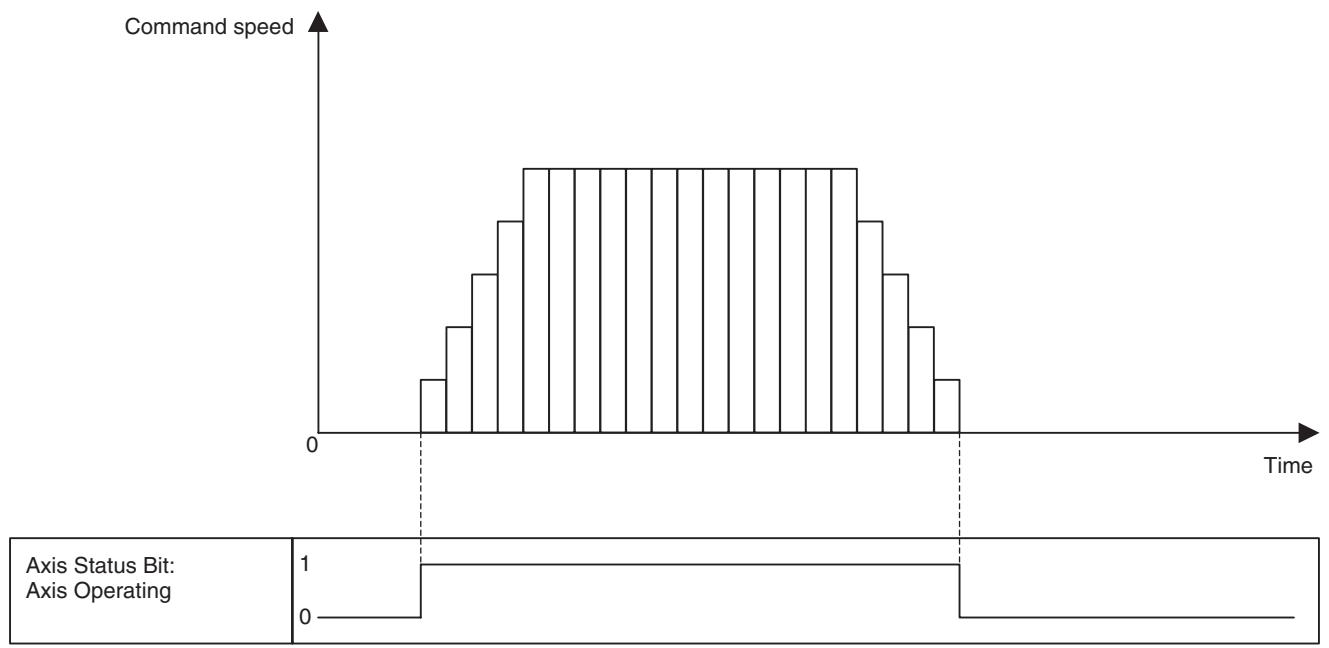
| Word | Variable | Bit | Name | I/O |
| x+32 | OW0440 | 06 | Positioning Completed (Axis 1) | Input |
| - | - | - | ||
| x+63 | OW045F | Positioning Completed (Axis 32) | ||
| x+32 | OW0440 | 07 | Positioning Completed (NO2.) (Axis 1) | |
| - | - | - | ||
| x+63 | OW045F | Positioning Completed (NO2.) (Axis 32) |
Function
The bits [Positioning Completed] and [Positioning Completed (NO.2)] indicate the status of positioning.
Status Condition
| Name | Specifications |
| Positioning Com-pleted | 0: Outputting positioning command, or axis is outside of in-position range. 1: Not outputting positioning command, and axis is within in-position range. |
| Positioning Com-pleted (NO2.) | 0: Outputting positioning command, or axis is outside of No.2 in-position range 1: Not outputting positioning command, and axis is within No.2 in-position range. |
-
The bit [Positioning Completed] will be turned ON when the difference between the present position and target position enters into the in-position range (specified in the servo parameter) after position command output was completed.
-
The bit [Positioning Completed (No.2)] will be turned ON when the difference between the present position and target position enters into the in-position range No.2 (specified in the system parameter) after position command output was completed.
-
Both bits [Positioning Completed] and [Positioning Completed (NO.2)] are turned OFF under the conditions described below:
-
Turned OFF simultaneously when the bit [Axis Operating] is turned ON in starting the position command output.
- When the parameter [P00004 bit04: Positioning completed signal select] is 0:
The bits will not be turned OFF until the bit [Axis Operating] is turned ON.
- When the parameter [P00004 bit04: Positioning completed signal select] is 1:
The bits will be turned OFF when moving out of the in-position range.
- In Speed or Torque control, the bits are always OFF because there is no target position.
- 1-shot output may occur. In that case, depending on the Scan Time of the ladder program and the Unit Scan Time of the MC Unit, the output may not be reflected in the ladder program.
Effect on Other Functions
- The bits function as the completion condition of the following axis operations:
| Function | Positioning completed/Positioning completed (NO.2) | Remark |
| Axis Control Bit: Origin Search | Positioning Completed | |
| Axis Control Bit: Machine Origin Return | Positioning Completed | |
| MOVEL Command: Linear Interpolation | Positioning Completed (NO.2) | In Stop Mode |
| MOVEC Command: Circular Interpolation | Positioning Completed (NO.2) | In Stop Mode |
| MOVETRAV Command: Traverse | Positioning Completed (NO.2) | In Stop Mode |
| MOVE: Positioning | Positioning Completed | |
| DATUM: Origin Search | Positioning Completed | |
| MOVEI: Interrupt Feeding | Positioning Completed | |
| MOVET: Time-specified Positioning | Positioning Completed | |
| CAM: Electronic CAM, Single Axis | Positioning Completed | |
| SYNCR: Synchronization Cancel | Positioning Completed | |
| SPEEDR: Speed Control Cancel | Positioning Completed | Switch to position control mode checked |
| TORQUER: Torque Control Cancel | Positioning Completed | Switch to position control mode checked |
| MOVELINK: Link Operation | Positioning Completed | Depends on link option |
| CAMBOX: Electronic Cam, Synchronous | Positioning Completed | Depends on link option |
- The bits also function as the start condition for the following functions:
| Function | Start condition |
| Axis Control Bit: Forced Origin | Cannot be executed when not ON |
| Axis Control Bit: ABS Origin Setting | Cannot be executed when not ON |
System Parameter
The range where the bits are turned ON/OFF is determined by the following system parameter:
| No. | Name |
| Pn0500 | In-Position Range |
| P3AA07 | No.2 In-Position Range |
Note
It is generally recommended to set the parameters above so that [Pn0500 = P3AA07] is satisfied for the sake of positioning and interpolation feed accuracy.
Timing Chart
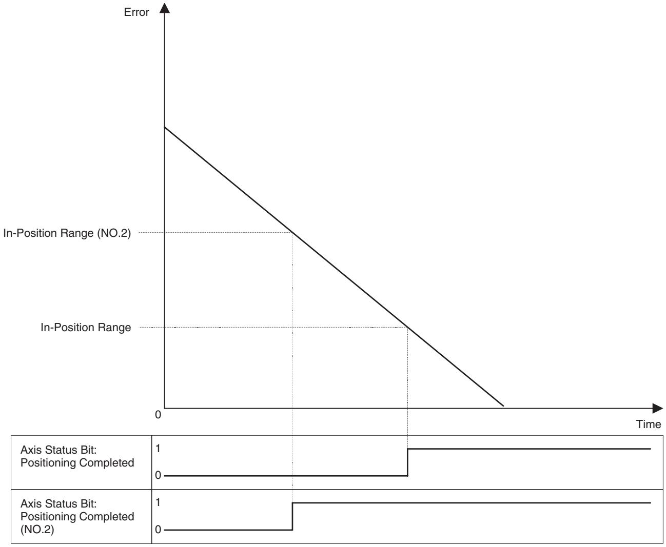
| Word | Variable | Bit | Name | I/O |
| x+32 | OW0440 | 08 | Error Counter Warning (Axis 1) | Input |
| - | - | - | ||
| x+63 | OW045F | Error Counter Warning (Axis 32) |
Function
The bit [Error Counter Warning] indicates the status of whether the error amount has exceeded the threshold value or not.
Status Condition
| Name | Specifications |
| Error Counter Warn-ing | 0: Error amount is within the range of the error counter warn-ing value.1: Error amount has exceeded the range of the error counter warning value. |
- The bit [Error Counter Warning] will be turned ON when the error amount exceeds the error counter warning value specified in the system parameter.
- Error amount is checked only during position command output.
- 1-shot output may occur. In that case, depending on the Scan Time of the ladder program and the Unit Scan Time of the MC Unit, the output may not be reflected in the ladder program.
Effect on Other Functions
This bit functions just as a warning, i.e. there is no effect whatsoever on any operations currently being executed.
System Parameter
The range where the bit is turned ON/OFF is determined by the following system parameter:
| NO. | Name |
| P3AA05 | Error Warning Value |
Timing Chart
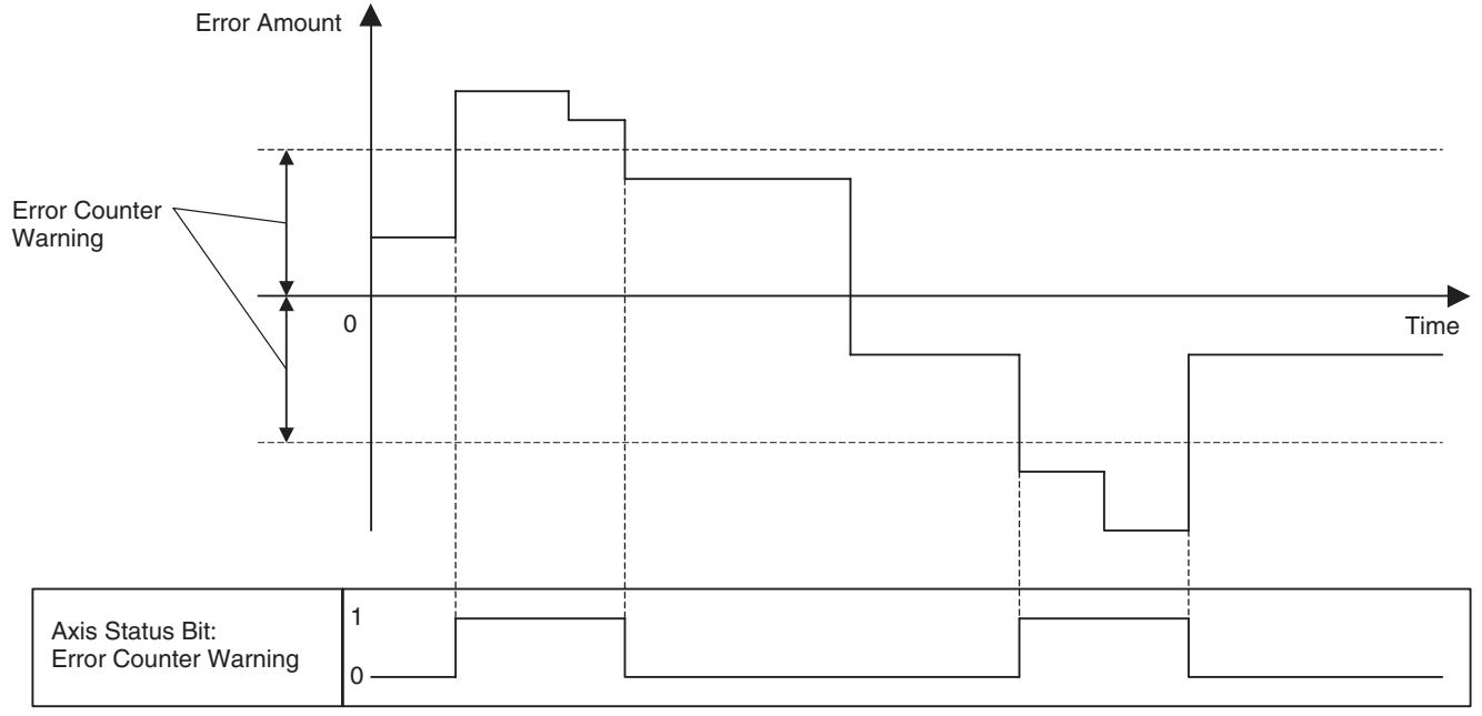
| Word | Variable | Bit | Name | I/O |
| x+32 | OW0440 | 10 | Counter Latch Completed (Axis 1) | Input |
| - | - | - | ||
| x+63 | OW045F | Counter Latch Completed (Axis 32) |
Function
The bit [Counter Latch Completed] indicates the counter latch status of the axis that has output the latch request through the operation of the following functions:
| Function | Purpose of counter latch function | Role of latch signal |
| DATUM: Origin Search | Detects origin. | Trigger to decide the final stop position |
| MOVEI: Interrupt Feeding | Detects external signal input position. | Trigger to decide the final stop position |
| MOVELINK: Link Operation | Detects link start position. | Trigger to start synchronization |
| CAMBOX: Electronic Cam, Synchronous | Detects link start position. | Trigger to start synchronization |
| SYNC: Trailing Synchronization | Detects marker sensor ON position. | Trigger to start synchronization |
| LATCH: Present Position Latch | Detects latch position. | Trigger to store latch position |
| Axis Control Bit: Origin Search | Detects origin. | Trigger to decide the final stop position |
Status Condition
| Name | Specifications |
| Counter Latch Completed | 0: Counter Latch not completed 1: Counter Latch completed |
The bit [Counter Latch Completed] will be turned ON when counter latch is completed, and turned OFF when counter latch is requested through the operation of the functions above.
Effect on Other Functions
The bit functions as the condition to carry forward the operation steps for the functions in the table above.
System Parameter
Nil
Timing Chart
Basic Operation (Interrupt Feeding):
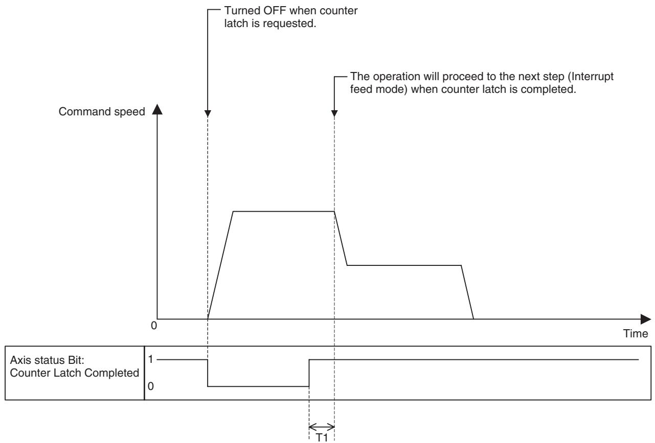
| Warning | Variable | Bit | Name | I/O |
| x+32 | OW0440 | 11 | MECHATROLINK Warning (Axis 1) | Input |
| - | - | - | ||
| x+63 | OW045F | MECHATROLINK Warning (Axis 32) |
Function
The MECHATROLINK Warning Bit will be set to 1 if a warning occurs in the MECHATROLINK-II slave.
Status Condition
| Name | Specifications |
| MECHATROLINK Warning | 0: No warning detected on MECHATROLINK-II device1: Warning detected on MECHATROLINK-II device |
1-shot output may occur. In that case, depending on the Scan Time of the ladder program and the Unit Scan Time of the MC Unit, the output may not be reflected in the ladder program.
Effect on Other Functions
- This bit functions just as a warning, i.e. there is no effect whatsoever on any operations currently being executed.
- Even if the bit [MECHATROLINK Warning] is turned ON, the bits [Alarm Occurring], [Axis Alarm Occurring 1-32], and [Axis Alarm] will not be turned ON. No alarm code will be stored in [Axis Alarm Code] neither.
- The warning code will be stored in the error log.
System Parameter Nil
Timing Chart Nil
| Warning | Variable | Bit | Name | I/O |
| x+32 | OW0440 | 12 | Main Power ON Bit (Axis 1) | Input |
| -x+63 | -OW045F | - | ||
| Main Power ON Bit (Axis 32) | ||||
| (Supported in Unit Ver. 3.0 or later) |
Function
- This bit indicates whether the Servo Driver's main circuit power is ON or OFF.
- When this bit is ON, the Servo can be locked.
Status Condition
| Name | Specifications |
| Main Power ON | 0: Servo Driver's main circuit power OFF. 1: Servo Driver's main circuit power ON. |
Effect on Other Functions Nil
System Parameter Nil
Timing Chart Nil
| Word | Variable | Bit | Name | I/O |
| x+32 | OW0440 | 13 | Command Disabled/Enabled (Axis 1) | Input |
| - | - | - | ||
| x+63 | OW045F | Command Disabled/Enabled (Axis 32) |
Function
The bit [Command Disabled/Enabled] indicates the status of whether the axis can accept a command or not.
Status Condition
| Name | Specifications |
| Command Disabled/Enabled | 0: Not allocated or not implemented 1: Allocated and implemented (1 for virtual axis unconditionally) |
- The bit for the axis that was allocated as a real axis will be turned ON when axis initialization processing is completed after communications were established. When disconnection due to communications error occurs, it will be turned OFF. Turning ON the bit [Axis Alarm Reset] may recover the communications from the disconnection.
- The bit for the axis that was allocated as a virtual axis will be turned ON when axis initialization processing is completed, and keeps the status until the MC Unit is switched OFF.
-
Other conditions for the bit [Command Disabled/Enabled] to be turned OFF are as follows:
-
When communications are disconnected
- During execution of MECHATROLINK device search
Effect on Other Functions
For the axes that were allocated as real axes, the bit [Command Disabled/Enabled] has effect on execution of all the commands and the status.
System Parameter
Nil
Timing Chart
Nil
| Word | Variable | Bit | Name | I/O |
| x+32 | OW0440 | 14 | Axis Not Used/Used (Axis 1) | Input |
| - | - | - | ||
| x+63 | OW045F | Axis Not Used/Used (Axis 32) |
Function
The bit [Axis Not Used/Used] indicates the status of whether the concerned axis can be used or not. The bit [Axis Not Used/Used] reflects the execution status as compared to the bit [Busy] will not be turned OFF until the command output is turned OFF. The bit [Busy] does not reflect status in Automatic Mode while the bit [Axis Not Used/Used] reflects status in Automatic Mode.
Status Condition
| Name | Specifications |
| Axis Not Used/Used | 0: Axis is not being used. 1: Axis is being used. (In Manual Mode: Axis is used for JOG etc., In Automatic Mode: Axis is declared in the operating program) |
- In Manual Mode, the bit [Axis Not Used/Used] is turned ON during execution of the following functions to indicate that the axis is being used in Manual Mode.
| Function |
| Axis Control Bit: JOG |
| Axis Control Bit: STEP |
| Axis Control Bit: Origin Search |
| Axis Control Bit: Machine Origin Return |
- In Automatic Mode, the bit [Axis Not Used/Used] for the axis declared in PROG command will be turned ON when the program is started to indicate that the axis is being used.
- 1-shot output may occur. In that case, depending on the Scan Time of the ladder program and the Unit Scan Time of the MC Unit, the output may not be reflected in the ladder program.
| Effect on Other Functions | ·In Manual Mode No effect. (The bit [Busy] also has effect on the functions affected by this bit. Duration of the bit [Busy] staying ON is longer than that of the bit [Axis Not Used/Used], which means that the bit [Busy] includes the bit [Axis Not Used/Used] consequentially. ·In Automatic Mode The axis for which the bit [Axis Not Used/Used] is ON cannot be used in other motion programs. When starting a program that declared an axis already in use, the bit [Start Warning] will be turned ON. Therefore, the motion program cannot be executed. |
| System Parameter | Nil |
| Timing Chart | For timing charts in Manual Mode, see “JOG operation” (page 476), “STEP operation” (page 480), “Origin Search” (page 484), and “Machine Origin Return” (page 489). For timing charts in Automatic Mode, see “Motion Program Start” and “Start Mode” (page 443). |
SECTION 8
Establishing the Origin
This section describes how to establish the origin in the positioning system.
8-1 Overview 532
8-1-1 UsingIncremental Encoders 532
8-1-2 Using Absolute Encoders 533
8-2 Input Signals Required for Origin search 534
8-3Origin Search Methods and Parameters 534
8-3-1 Origin Search Methods 534
8-3-2 System Parameters 535
8-4Origin Search Operations 536
8-4-1 Overview 536
8-5 Absolute (ABS) Encoders 539
8-6 ABS Encoder Origin Setting 540
8-6-1 Procedure. 540
8-6-2 Setting Up the Related Parameters 540
8-6-3 Setting Up the Absolute Encoder 541
8-6-4 Supplemental Information for Setting Up. 543
8-6-5 Moving to the Origin. 543
8-6-6 Setting the MC Unit ABS Origin 543
8-1 Overview
This section describes the method of establishing the origin for motion control systems using either incremental encoders or absolute encoders.
8-1-1 Using Incremental Encoders
In motion control systems using incremental encoders, an origin must be established and the bit [No Origin] must be turned OFF after the power is turned ON.
There are two ways to establish the origin using the MC Unit.
| Operation | Description |
| Forced Origin | The position where the motor is stopped is defined as an ori-gin. |
| Origin search | Actually moving the motor and using the limit switches, origin proximity switches, and encoder's phase-Z signal determine an origin.If the origin search method is set to “Origin at power ON” in the system parameter, the Unit will automatically define the position where the power is turned ON as the origin, without moving the motor. |
Forced Origin
The position where the motor is stopped is determined as the origin (forcibly clear to 0) by turning ON the bit [Forced Origin] in the PC Interface Area. See "Forced Origin" (page 498) in SECTION 7 PC Interface Area for details on the timing chart and other details.
| Word | Variable | Bit | Name | Description |
| x+0 | IW0440 | 09 | Forced Origin (Axis 1) | 0: Nil |
| - | - | - | 1: Nil | |
| x+31 | IW045F | Forced Origin (Axis 32) | ↑: The present position is defined as the origin on the machine coordinate system (disabled during operation). ↓: Nil |
Origin Search
An origin search operation can be performed by turning ON the bit [Origin Search] or by executing DATUM command (Origin Search).
| Word | Variable | Bit | Name | Description |
| x+0 | IW0440 | 06 | Origin Search (Axis 1) | 0: Nil |
| - | - | - | 1: Continues origin search | |
| x+31 | IW045F | Origin Search (Axis 32) | ↑: Starts origin search | |
| ↓: Stops origin search |
Origin Search in Manual/Automatic Mode
Following the method of determining an origin, use one of the methods depending on the mode of each task as shown below:
Yes: Can be used, No: Cannot be used
| Method | Manual Mode | Automatic Mode | |
| Forced Origin bit | Yes | No | |
| Origin Search | [Origin Search] bit | Yes | No |
| DATUM | No | Yes | |
8-1-2 Using Absolute Encoders
With the ABS encoder, the present position can be defined by reading the absolute value from the encoder when the MC Unit is turned ON if the PLC (MC Unit) or servo driver was turned OFF once. Because of this, there is no need to perform origin searches every time when turning ON the devices. This section explains the set up procedure briefly.
For details, see 8-5 Absolute (ABS) Encoders (page 539).
Absolute Encoder Setup
Absolute encoder data must be reset and the absolute origin for the MC Unit must be set in the following cases:
- When a Servomotor with an absolute encoder is connected for the first time or replaced
- When the battery is replaced.
- When the held absolute data is lost because the encoder cable has been plugged OFF for a long time.
Use the following procedure to set up the absolute encoder:
1,2,3...
- Connect the motor to the machine.
- Referring to the Servo Driver operation manual, replace the battery.
- Referring to the Servo Driver operation manual, held values are cleared (data reset). At this point, the origin of the absolute encoder and the machine origin do not match with each other.
- Execute Servo Lock using the MC Unit.
- Perform an origin search to move the Servomotor axis to the origin.
- Turn the absolute encoder OFF and ON in order to save the present value as the origin. The absolute encoder value indicating the machine origin is stored as absolute an origin setting value.
Once the setup is completed, since the present value is decided by automatically subtracting the ABS origin setting value from the value read from the encoder when the power is turned ON, no origin search will be required. For details, see 8-6 ABS Encoder Origin Setting (page 540).
| Word | Variable | Bit | Name | Description |
| x+0 | IW0440 | 09 | ABS Origin Setting (Axis 1) | 0: Nil |
| - | - | - | 1: Nil | |
| x+31 | IW045F | ABS Origin Setting (Axis 32) | ?: Sets ABS encoder origin | |
| ?: Nil | ||||
| x+0 | IW0440 | 06 | Origin Search (Axis 1) | 0: Nil |
| - | - | - | 1: Continues origin search | |
| x+31 | IW045F | Origin Search (Axis 32) | ↑: Starts origin search | |
| ↓: Stops origin search |
See 7-4 Interface Specifics (page 420) for details on each bit.
8-2 Input Signals Required for Origin search
The following input signals and conditions are required to perform the origin search operation.
| Parameter | Description |
| CW/CCW Limit Signals | Normally closed switches are required. |
| Origin Proximity Signal | The logic of the input signal can be changed in the parameter, so either Normally closed or Normally open switch can be used. |
| Encoder Phase-Z Signal | Built-in signal of the encoder on the servomotor. |
| External Input Signal 1,2, and 3 | Normally open switches are used, and connected to the servo driver. |
CW/CCW Limit Signals
These signal inputs indicate the maximum operating range of the work when the motor rotates in the direction of clockwise (CW) or counterclockwise (CCW).
Origin Proximity Signal
This signal input indicates that the axis is near the origin.
Encoder Phase-Z Signal
This signal will be output when the encoder makes one revolution.
The first phase-Z input position after the origin proximity signal input changes from ON to OFF becomes the actual machine origin.
External Input signal 1,2, and 3
Instead of encoder phase-Z signal, one of these signals determines the actual machine origin. The signal to be used can be selected in the system parameter [P4AA06: Origin determine signal].
8-3 Origin Search Methods and Parameters
8-3-1 Origin Search Methods
There are four possible settings for the origin search methods.
Origin at Power ON Mode
- The position of the motor when the power is turned ON is defined as the origin automatically.
- If an origin search is performed in this mode, the position where the origin search is started will become the origin.
Limit Reversal Mode
- The direction will be reversed if a limit input signal is input during the origin search.
- After starting the operation towards Origin search start direction at Origin search feed rate, when Origin proximity signal input (normally open) is turned ON, the speed will be changed to Origin search approach speed. At the rise of Origin determine signal input after the Origin proximity signal input has been turned OFF, the speed is changed to Origin search creep speed. The axis travels for the final travel distance to define an origin.
- When there is no Origin proximity signal input, a limit signal input can be used instead.
2-level Speed in One Direction Mode
- The origin search is performed only in one direction.
- After starting the operation towards the phase-Z detection direction at Origin search approach speed, the speed will be changed to Origin search creep speed at the rise of the Origin determine signal input and the axis travels for the final travel distance to define an origin. An alarm will occur if a limit signal input is received before the origin proximity signal input.
3-level Speed in One Direction Mode
- The origin search is performed only in one direction.
- After starting the operation towards the phase-Z detection direction at Origin search feed rate, the speed will be changed to Origin search approach speed when the Origin proximity signal input (normally open) is turned ON. The speed will be changed to the Origin search creep speed at the rise of the Origin determine signal input after the Origin proximity input signal is turned OFF and the axis travels for the final travel distance to define an origin.
- An alarm will occur if a Limit input signal is input before the Origin proximity input signal.
- When there is no Origin proximity input signal, a limit input signal can be used instead.
8-3-2 System Parameters
The following system parameters are required to perform the origin search operation. These system parameters are set using the Support Tool.
- Except for "Origin at power ON" mode, the origin on the machine coordinate system is determined with the external input signal specified in the parameter [P4AA06: Origin determine signal].
-
After completion of an origin search, the following values remain the same as before the execution.
-
The workpiece coordinate system offset set using OFFPOS command
-
The coordinate system No. set in ORIGIN/WORK command
-
If an origin search is executed for an axis using an absolute encoder, the origin on the machine coordinate system will be determined using an external input signal.
- By specifying Origin offset value, the origin on the machine coordinate system after an origin search can be set to the value other than zero. (Specify zero if not necessary.)
| Parameter | No. | Value | Description |
| Origin search method | P4AA01 | 0: Origin at power ON1: Limit reversal2: 2-level speed in one direction3: 3-level speed in one direction | Sets the origin search method. |
| Initial search direction | P4AA02 | 0: Same as phase-Z detection1: Opposite of phase-Z detection | Sets the origin search start direction in Limit reversal mode (origin search method 1). |
| Phase-Z detection direction | P4AA03 | 0: + direction1: - direction | Sets the phase-Z detection direction in the modes (origin search methods 1,2, and 3) except for Ori-gin at power ON mode. |
| Origin deceleration method | P4AA04 | 0: Uses origin proximity1: Uses CW/CCW | Sets whether to use origin proximity or limit input signal as the origin proximity signal for origin search methods 1 and 3. |
| Origin determine signal | P4AA06 | 0: Phase-Z1: External input signal 12: External input signal 23: External input signal 3 | Sets the signal that determines the origin. |
| Origin search feed rate | P4AA07 | 1 to 2147483647Note The speed is limited by 32767 command unit/unit scan. | Sets the \( 1^{st} \) level speed of the 3-level speed origin search. |
| Origin search approach speed | P4AA08 | 1 to 2147483647Note The speed is limited by 32767 command unit/unit scan. | Sets the 2ndlevel speed of the 3-level speed origin search, or sets the 1stlevel speed of the 2-level speed origin search. |
| Origin search creep speed | P4AA09 | 1 to 2147483647Note That the speed is limited by 32767 command unit/unit scan. | Sets the 3rdlevel speed of the 3-level speed origin search, or sets the 2ndlevel speed of the 2-level speed origin search. |
| Reference (machine) origin offset | P4AA10 | -2147483648 to 2147483647 | Sets the offset amount for the origin search. It is not used for DATUM. |
| Origin search final travel distance | P4AA11 | 0 to 2147483647 | Sets the origin search final travel distance, which is an additional travel distance towards the travel direction. |
8-4 Origin Search Operations
8-4-1 Overview
Origin at Power ON Mode
This section provides basic examples of origin search patterns for each mode.
The position of the motor when the power is turned ON is automatically defined as the origin. Therefore, there is no origin search operation.
Limit Reversal Mode
With Origin proximity input signal, Phase-Z detection direction: + direction, Origin search start direction: Same as Phase-Z detection
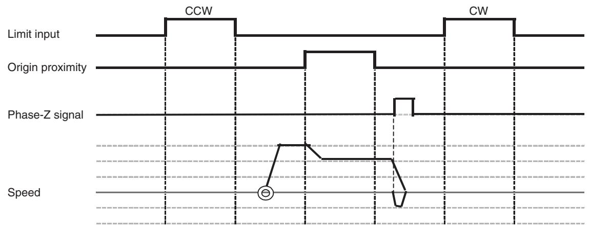
When the final travel distance is zero:
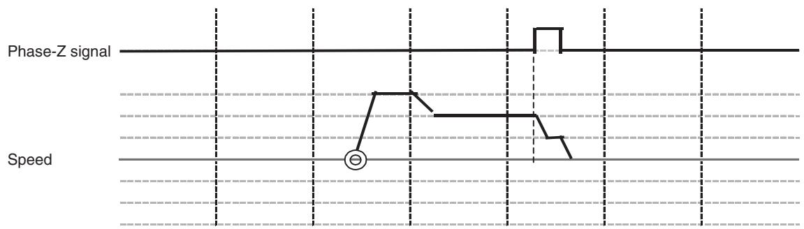
When the final travel distance is specified:
Description
1,2,3...
- When the origin search is executed, the axis is moved in the specified direction at the specified origin search feed rate.
- When the origin proximity input signal is input, the speed is changed to the origin search approach speed.
- After the origin proximity input signal is turned OFF, the speed is reduced at the first rise of phase-Z.
-
The machine origin will be defined after the axis travels back for the excess distance at the origin search creep speed.
-
If the final travel distance has been specified, the machine origin will be defined after the axis travels back for the specified distance.
- If the reference origin offset value has been set in the system parameter, the specified value will be the machine coordinate of the stopping position.
- The origin search operation and alarm occurrence will vary depending on the input timings of limit input signal, origin proximity input signal, and phase-Z, origin search start direction, and the position of the work when executing the origin search.
2-level Speed in One Direction Mode
When the phase-Z detection direction is + direction:
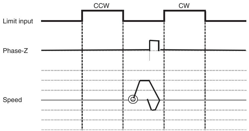
When the final travel distance is zero:
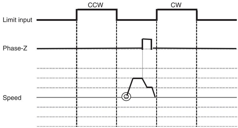
When the final travel distance is specified:
Description
1,2,3...
- When the origin search is executed, the axis is moved in the phase-Z detection direction at the origin search approach speed.
- After the origin proximity input signal is turned OFF, the speed is reduced at the first rise of the phase-Z.
-
The machine origin will be defined after the axis travels back for the excess distance at the origin search creep speed.
-
If the final travel distance has been specified, the machine origin will be defined after the axis travels back for the specified distance.
- If the reference origin offset value has been set in the system parameter, the specified value will be the machine coordinate of the stopping position.
- The origin search operation and alarm occurrence will vary depending on the input timings of limit input signal, origin proximity input signal, and phase-Z, origin search start direction, and the position of the work when executing the origin search.
3-level Speed in One Direction Mode
With Origin proximity input signal, Phase-Z detection direction: + direction
When the final travel distance is zero:
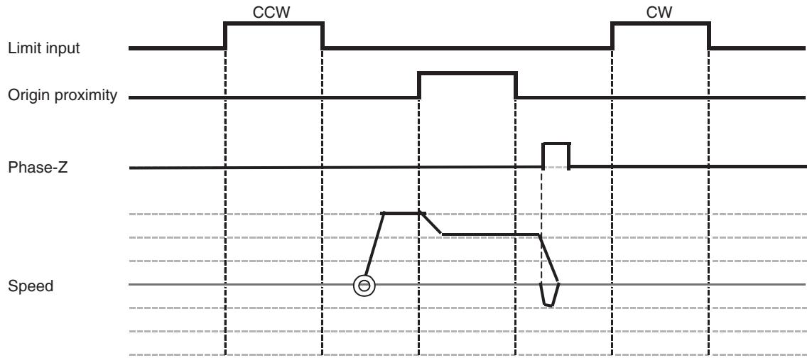
When the final travel distance is specified:
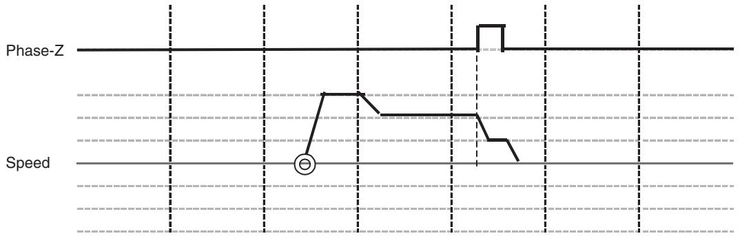
Description
1,2,3...
- When the origin search is executed, the axis is moved in the specified direction at the specified origin search feed rate.
-
When the origin proximity input signal is input, the speed is changed to the origin search approach speed.
-
After the origin proximity input signal is turned OFF, the speed is reduced at the first rise of phase-Z.
-
The machine origin will be defined after the axis travels back for the excess distance at the origin search creep speed.
-
If the final travel distance has been specified, the machine origin will be defined after the axis travels back for the specified distance.
- If the reference origin offset value has been set in the system parameter, the specified value will be the machine coordinate of the stopping position.
- The origin search operation and alarm occurrence will vary depending on the input timings of limit input signal, origin proximity input signal, and phase-Z, origin search start direction, and the position of the work when executing the origin search.
8-5 Absolute (ABS) Encoders
Overview
The absolute encoder retains absolute data by using the backup battery when the MC Unit is turned OFF. When PLC (MC Unit) is turned ON again, the absolute data is read from the absolute encoder to determine the present position. Therefore, once an origin is set, no origin search will be required after the power is turned ON (required for INC encoders).
The absolute position can be detected using the absolute encoder on the motor with a semi-closed loop system. The detector is composed of an encoder detecting the absolute position within one rotation and a counter that counts the number of rotations.
The ABS data that is stored in the ABS encoder consists of [the number of rotations from the absolute reference position (M)] and [the position within one encoder rotation (PO)]. This ABS data is read as serial data when the power for the system is turned ON. After that, the operation of an absolute encoder will be the same as that of an incremental encoder.
The absolute position PE can be found using the following expression:
$$ P E = M \times R + P O $$
Number of rotations from the absolute reference position: M
Number of pulses per one encoder rotation: R
- The position within one encoder rotation: PO
The ABS encoder constantly holds the ABS data using battery even when the power is OFF. Moreover, it updates the data when there is any data change.
The battery is connected to the battery connector of the Servo Driver.
The Servo Driver reads the absolute data when the power is turned ON. Additionally, the MC Unit reads the same data to calculate the absolute position to set the machine coordinate system automatically.
Applicable Absolute Encoders
The following Servomotors with absolute encoders that can be connected to the MC Unit are provided:
OMRON W Series (R88M-W□□□□S)
(R88M-W□□□□T)
8-6 ABS Encoder Origin Setting
8-6-1 Procedure
Follow the procedure below to set the ABS encoder origin.
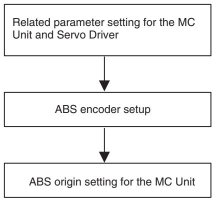
Follow the above procedure in the following cases:
- When starting up the absolute position detection system for the first time
- When the servomotor was replaced
- When alarm related to the absolute encoder occurred
8-6-2 Setting Up the Related Parameters
Parameters of MC Unit
| No. | Name | Value | Remark |
| P1AA01 | Physical axis setting | 0: Not used1~30: MLK devices31: Reserved32: Virtual axis | Only the MLK slaves can be used as the absolute value detection system. |
| P4AA12 | ABS origin offset | -2147483648~2147483647 | Sets the offset amount for the ABS origin setting.The present position after ABS origin setting execution will be the value set in this parameter. |
| P5AA04 | Command unit/1 machine rotation | 1~2147483647 | |
| P5AA05 | Gear ratio 1(Motor rotation speed) | 1~10,000,000 | |
| P5AA06 | Gear ratio 2(Machine rotation speed) | 1~10,000,000 | |
| P5AA07 | Axis feed mode | 000000X0hX (coordinate system management)0: Limited length1: Unlimited length | Coordinate system management:Limited length axis and Unlimited length axis are treated differently. |
Note If the parameters [P5AA04], [P5AA05], and [P5AA06] are changed after ABS origin setting, the alarm [300Dh: ABS encoder error] may occur when the power is turned ON.
Parameters of Servo Driver
| No. | Name | Value | Remark |
| Pn002.2 | Absolute encoder usage | 0: Uses absolute encoder as absolute encoder. 1: Uses absolute encoder as incremental encoder. | Set 0. |
| Pn205 | Multi-turn limit setting | 0~65535 | Limited length axis: 65535 (Default value) Unlimited length axis: Denominator of the deceleration ratio -1 (See note 1.) |
| Pn813.0 | Option monitor 1 select | 0: Follows analog monitor 1 (Pn003.0) 1: Follows analog monitor 1 (Pn003.1) 2: Initial multi-turn data (IMTDATA) 3: Encoder count direct value (PGCNT: after x4) 4: Motor PG initial multi-turn data direct value 5: Motor PG counter direct value 6: Motor PG counter latch direct value 7: Reserved 8: Full-closed PG counter direct value 9: Full-closed PG counter latch direct value | Set 2. (See note 2.) |
| Pn813.1 | Option monitor 2 select | Same as above | Set 3. (See note 2.) |
Note
(1) With machines such as turntable whose motor makes m rotations while its load shaft makes n rotations, the present value cannot be displayed correctly unless the multi-turn data from the ABS encoder returns to zero in every m rotations. Setting the value obtained by subtracting 1 from deceleration ratio denominator (m-1) in Pn205 will enable to display the present value correctly.
(2) Both multi-turn data and initial incremental pulses are read through the option monitor 1/2 when the power is turned ON. Set the parameters Pn813.0 and Pn813.1 appropriately so that the absolute data can be read correctly.
8-6-3 Setting Up the Absolute Encoder
Purpose
ABS encoder setup is required when clearing the rotational count data of the encoder to 0, or when the encoder has been left disconnected from the battery for a long period. Along with the ABS encoder setup, ABS origin must be set in the MC Unit. This is for resetting rotational count data of the ABS encoder, which should be accompanied by initialization of the axis present value to 0 in the MC Unit.
Setup Procedure
The following setup procedure is for the ABS encoder on OMRON W-series Servomotor.
Make sure to follow the procedure. Otherwise, errors may occur.
1,2,3... 1. Execute ABS encoder setup in the system check mode (Fn008).
ABS encoder setup in the system check mode
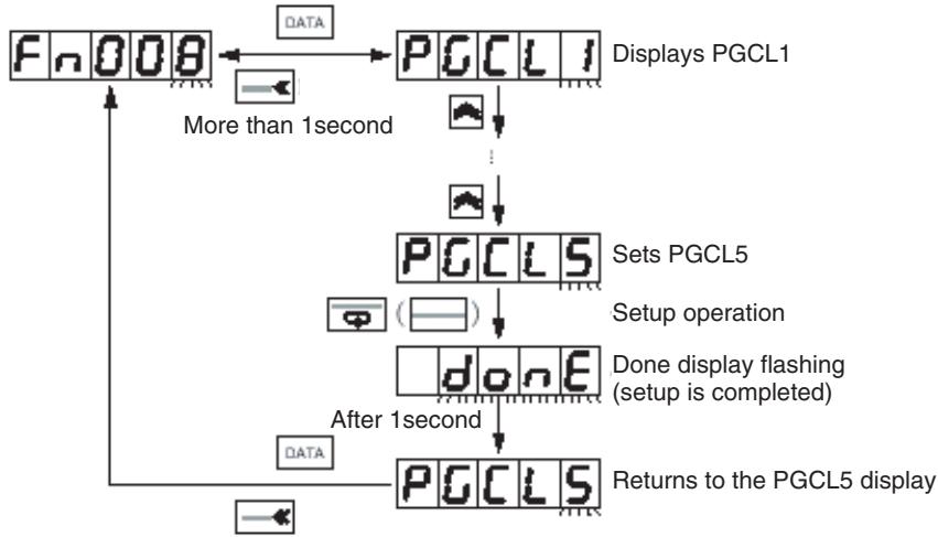
More than 1second
Operation procedure
| PR02W OPR | Key OPR | Display | Description |
| F.R.B.I | Status display mode Note When the power is turned ON for the first time after connecting the motor with absolute encoder, A.81 (backup error) will be displayed. | ||
| FnO00 | Press the key to select the system check mode. | ||
| FnO08 | Press the key to select the function No. Fn008. | ||
| PGCL | (More than 1 second) Press the key to start the ABS encoder setup function. "PGCL1" will be displayed. | ||
| PGCLS | Press the key to display "PGCL5". | ||
| do nE | Press the key. The ABS encoder setup will be processed. After completing the setup, "donE" will be displayed and flash for about 1 second. | ||
| After 1 second | PGCLS | After displaying "donE", "PGCL5" will be displayed again. | |
| DATA | More than 1second | FnO08 | (More than 1 second) Function No. in the system check mode will be displayed again. |
2. Turn OFF the power once, and then ON again.
The alarm (A.81) will not be cleared when the setup operation is completed.
The alarm will be cleared after the power is turned OFF once (check the power-indicator goes OFF), and then ON again. If no error occurs after power ON, the setup is completed.
If the alarm (A.81) occurs, start over the setup operation.
8-6-4 Supplemental Information for Setting Up
| Setup operation explained above is required for operation check (with no load) on a motor and driver alone. When connecting the motor with the mechanical system for trial operation, another setup will be required due to the possibility that the amount of multi-turns in the ABS encoder may be too great. | |
| Note | The output range of the ABS encoder multi-turns for OMNUC W Series is between -32768 to +32767. Make sure that the operation range of the machine is within the range of multi-turns output. |
| Setting Up for Trial Operation | • If the alarm (A.81) occurs after replacing the battery unit, another setup will be required. • The multi-turn data after the replacement should be different from that before battery unit replacement. Therefore, another initialization of the MC Unit will be required. |
| Note | If the alarm does not occur after battery unit replacement, it is not necessary to initialize the MC Unit. If the battery unit is replaced correctly before its battery drain, no alarm should occur normally. |
| Setting Up When Replacing the Battery unit | In case of battery drain, the absolute data in the ABS encoder will be cleared. Therefore, battery unit replacement and setup are required. |
| Other Cases Requiring Setup | When disconnecting the encoder cable from the connector (on the driver or motor), the absolute data in the ABS encoder will be cleared. Therefore, setup operation will be required again. |
8-6-5 Moving to the Origin
Use either of the following methods to move the machine to the position that will be the origin.
- Perform an origin search
- Execute JOG operation without an origin search.
Performing an Origin Search
1,2,3... 1. Set the system in Servo Lock.
2. Perform an origin search. See 8-4 Origin Search Operations (page 536) for details on the origin search.
Jog Operation Without Performing an Origin Search
1,2,3... 1. Set the system in Servo Lock
2. Move the axis to the position to be the origin by JOG operation.
8-6-6 Setting the MC Unit ABS Origin
By setting the ABS origin, while the present position on the machine coordinate system is cleared to zero, the absolute position at that point is stored in the Flash memory.
Execute ABS origin setting after the axis was moved to the origin.
The present position (stopping) is stored in the MC Unit as the absolute origin.
Execute ABS origin setting using the bit in the PC Interface Area.
| Name | Word | Variable | bit | Name | Description |
| Axis 1 Control Bit | x+0 | IW0440 | 10 | Absolute Origin Setting | 0: Nil1: Nil↑: Sets ABS encoder origin↓: Nil |
| Axis 2-32 Control Bits | x+1- x+31 | IW0441 - IW045F | 10 | The same as for Axis 1 | The same as for Axis 1 |
- The absolute position setting value is stored in the system variable after ABS origin setting is completed. It is possible to transfer the absolute position setting value to another MC Unit through backup/restore operation using the CPU Unit's memory card.
- The absolute position setting value can be referenced using IORD instruction or the Support Tool. However, they cannot be edited directly. Make sure to set the absolute position setting value using ABS origin setting function.
- The addresses in the table below are for Axis 1:
| Variable address | IORD address | Classi-fication | Name | Description | Unit | Update timing |
| SW021E | 310F | Axis | Axis 1 Status: Absolute position setting value 1: Multi-turns | The value of multi-turns of the ABS encoder in ABS origin setting | Rotation | At power ON, At ABS origin setting completion |
| SW021F | ||||||
| SW0220 | 3110 | Axis | Axis 1 Status: Absolute position setting value 2: Initial incremental pulses | The number of initial incre-mental pulses of the ABS encoder in ABS origin setting | Pulse | At power ON, At ABS origin setting completion |
| SW0221 |
Note
(1) It is recommended to backup the contents of ABS origin setting in the CPU Unit's memory card after ABS origin setting is completed.
(2) Make sure to set the absolute position setting value correctly. Otherwise, difference in values for positioning will occur between the MC Unit and ABS encoder.
(3) Do not execute ABS origin setting at least for one second after the main power supply for the Servo Driver or control power supply is turned ON.
SECTION 9
Other Operations
This section describes special operations for the CJ1W-MCH71 and CS1W-MCH71 Motion Control Units, including teaching, program debugging, coordinate systems, and backup functions.
9-1 Teaching 546
9-1-1 Introduction 546
9-1-2 Teaching Condition Setting. 546
9-1-3 Teaching Execution 547
9-1-4 Teaching Status 547
9-1-5 List of Related Bits 548
9-1-6 Program Example 549
9-1-7 TimingChart 550
9-2 Debugging the Program 553
9-2-1 Single Block Operation 553
9-2-2 Machine Lock 555
9-3 Coordinate System. 558
9-3-1 Machine Coordinates and Workpiece Coordinates 558
9-3-2 Limited Length Axis and Unlimited Length Axis 559
9-3-3 Software Limit. 561
9-3-4 Absolute Value Detection Function. 562
9-4 Backup and Restore Function 566
9-4-1 Procedures for Backup and Restore 568
9-5 Servo Driver Status Output 569
9-6 Data Tracing 570
9-7 Zones 571
9-1 Teaching
This section describes the teaching method using the PC Interface Area.
9-1-1 Introduction
- After moving the axis to a desired position, the present position can be written into the words for position data. This process is called teaching. The address to which the present position is written is called teaching address.
- Teaching is performed for the entire unit. The axis on which teaching is executed can be specified in "Teaching axis setting".
- When the teaching command is executed, the present position of the specified axes will be stored in the words of the teaching address specified with position data in ascending order of Axis No.
-
In Teaching, the present position on the reference coordinate system is always read. Either of the following two formats of the present position can be specified.
-
The target position (present position of the command)
- The feedback value (actual present position calculated with the encoder feedback value)
- To execute teaching, the bit [Command Disabled/Enabled] has to be ON (Command Enabled) and the bit [No Origin] has to be OFF (Origin is defined).
9-1-2 Teaching Condition Setting
- The teaching axes and teaching addresses are determined when the bit [Teaching Condition Setting] is turned ON.
- When the condition setting is completed, the bit [Teaching Condition Setting Completed] will be turned ON, which turns OFF the bit [Teaching Condition Setting]. After that, the bit [Teaching Condition Setting Completed] will be turned OFF.
- In order to check whether teaching was completed normally or not, observe the bit [Teaching Warning] when the bit [Teaching Condition Setting Completed] is turned ON.
Teaching Axis Setting
When executing teaching, the present position of which axis is to be read has to be specified. It can be specified with Teaching axis setting. Teaching axis setting 1-16 is for Axes 1 to 16 and Teaching axis setting 17-32 is for Axes 17 to 32. To make an axis a teaching object, turn ON (1) the bit corresponding to the Axis No.
Teaching Address
Teaching address specifies the address of position data in which the present position of axes is to be stored. Having the specified address as the beginning word, the present positions will be written into the words of position data in ascending order of Axis No. If Teaching condition setting is not executed after teaching execution, the teaching address will be automatically incremented for the number of axes that have been specified in the bits [Teaching Axis Setting 1-16], [Teaching Axis Setting 17-32]. If the incremented teaching addresses exceed 10239 (27FFh), the address will go back down to zero.
9-1-3 Teaching Execution
- The bit [Teaching Type] will be read when the bit [Teaching Execution] is turned ON, and the present values will be written into the position data under the conditions specified in the [Teaching Condition Setting].
- When the present position is written successfully, the bit [Teaching Execution Completed] will be turned ON, which turns OFF the bit [Teaching Execution]. After that, the bit [Teaching Execution Completed] will be turned OFF.
- In order to check whether teaching was completed normally or not, observe the bit [Teaching Warning] when the bit [Teaching Condition Setting Completed] is turned ON.
- It is possible to turn ON the bits [Teaching Condition Setting] and [Teaching Execution] simultaneously to execute them together. However, if an error occurs, it will not be possible to know in which operation the error occurred. Therefore, condition setting and execution should be executed separately.
Teaching Type
Either the feedback present position or command present position can be specified for the teaching present value.
9-1-4 Teaching Status
Teaching Warning
The bit [Teaching Warning] indicates the error status of the bits [Teaching Condition Setting] and [Teaching Execution]. The bit [Teaching Warning] is turned ON simultaneously with the bits [Teaching Condition Setting] and [Teaching Execution Completed] under the following conditions:
When Setting Teaching Condition:
- The teaching axes are not set. ([Teaching Axis Setting 1-16] = [Teaching Axis Setting 17-32] = 0)
- There are unallocated axes among the axes being specified in the bits [Teaching Axis Setting 1-16] and [Teaching Axis Setting 17-32].
- The address specified in [Teaching Address] is outside of the position data addresses.
- Adding the number of axes that have been specified in the bits [Teaching Axis Setting 1-16] and [Teaching Axis Setting 17-32] to the address specified in [Teaching Address] exceeds the position data address range.
When Executing Teaching:
- The bit [Teaching Execution] is turned ON when the teaching condition has not been set.
- For any of the axes specified in the bits [Teaching Axis Setting 1-16] and [Teaching Axis Setting 17-32], The bit [Command Disabled/Enabled] is OFF, or the bit [No Origin] is ON.
- Adding the number of teaching axes to the address indicated in [Teaching Address Monitor] exceeds the position data address range.
Teaching Condition Setting Completed
- The bit [Teaching Condition Setting Completed] indicates completion of teaching condition setting regardless of normal or error completion.
- It will be turned OFF when the bit [Teaching Condition Setting] is turned OFF.
Teaching Execution Completed
- The bit [Teaching Execution Completed] indicates completion of teaching execution regardless of normal or error completion.
Teaching Address Monitor
- It will be turned OFF when the bit [Teaching Execution] is turned OFF.
- The status [Teaching Address Monitor] indicates the teaching address.
- When teaching is completed normally, the address displayed in [Teaching Address Monitor] will be automatically incremented for the number of axes specified in the bits [Teaching Axis Setting 1-16] and [Teaching Axis Setting 17-32].
9-1-5 List of Related Bits
CIO Area Words for Unit (CPU Unit to MC Unit)
| Classification | Word | Variable | bit | Name | Specifications |
| Unit Control bits | n+0 | IW0300 | 03 | Teaching Condition Setting | 0: Nil 1: Nil ↑: Reads [Teaching Axis Setting] and [Teaching Address]. ↓: Nil |
| 04 | Teaching Type | 0: Feedback present position 1: Command present position ↑: Nil ↓: Nil | |||
| 05 | Teaching Execution | 0: Nil 1: Nil ↑: Writes the present position of the selected teaching type into the position data. ↓: Nil: | |||
| n+1 | IW0301 | 00-15 | Teaching Axis Set- ting 1-16 | 0: Nil 1: Specifies the axis as teaching object ↑: Nil ↓: Nil | |
| n+2 | IW0302 | 00-15 | Teaching Axes Set- ting 17-32 | 0: Nil 1: Specifies the axis as teaching object ↑: Nil ↓: Nil: |
CIO Area Words for Unit (MC Unit to CPU Unit)
| Classification | Word | Variable | bit | Name | Specifications |
| Unit Status bits | n+15 | OW0303 | 03 | Teaching Warning | 0: Teaching condition setting, and the execution completed normally 1: Condition error, Command disabled, No origin, or address overflow |
| 04 | Teaching Condition Setting Completed | 0: [Teaching Condition Setting] is OFF. 1: Teaching condition setting is completed (including error completion). | |||
| 05 | Teaching Execution Completed | 0: [Teaching Execution] is OFF. 1: [Teaching Execution] is completed (including error completion). |
DM Area Words for Unit (CPU Unit to MC Unit)
| Classification | Word | Variable | bit | Name | Specifications |
| Unit Control bit | m+20 | IW0310 | 00-15 | Teaching Address | Specifies the teaching start address 0-10239 |
DM Area Words for Unit (MC Unit to CPU Unit)
| Classification | Word | Variable | bit | Name | Specifications |
| Unit Status data | m+39 | OW0311 | 00-15 | Teaching Address Monitor | Outputs the address of the current teaching object. |
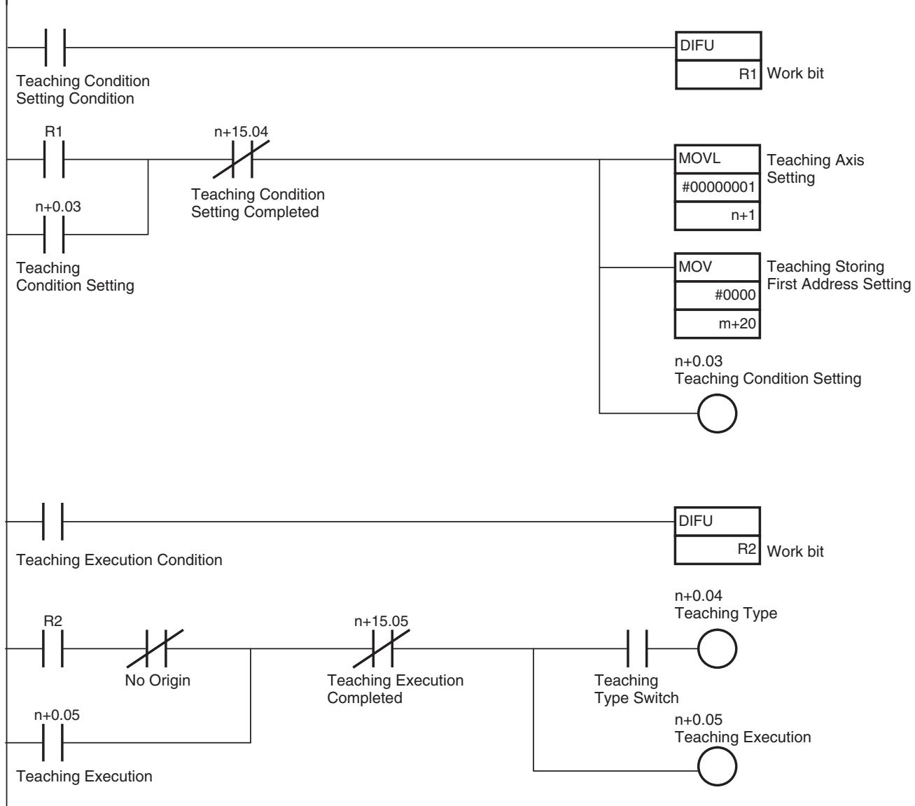
9-1-6 Program Example
9-1-7 Timing Chart
Teaching Condition Setting (Normal completion):
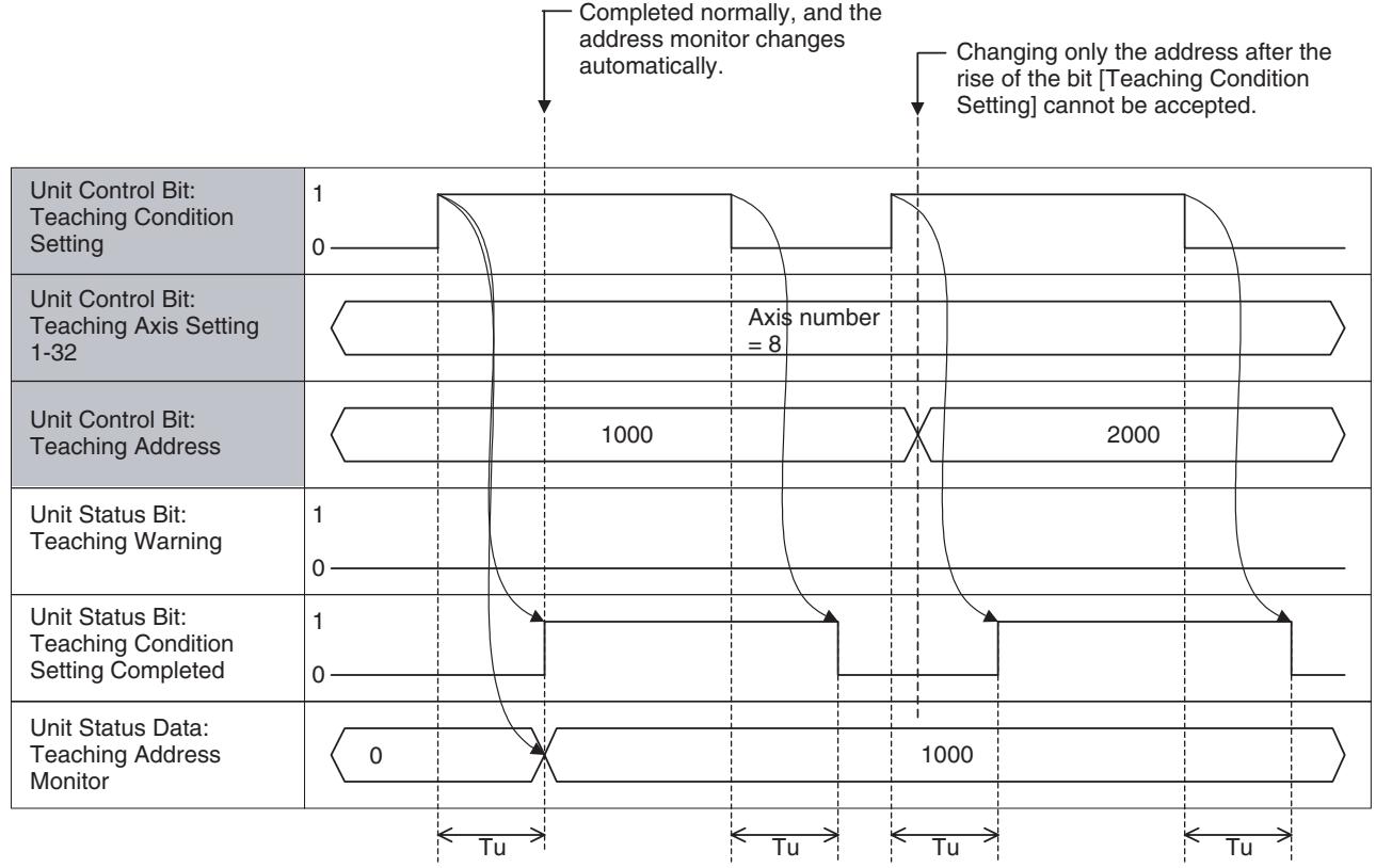
Teaching Condition Setting (Error completion):
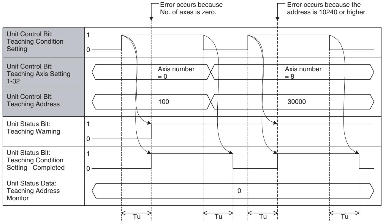
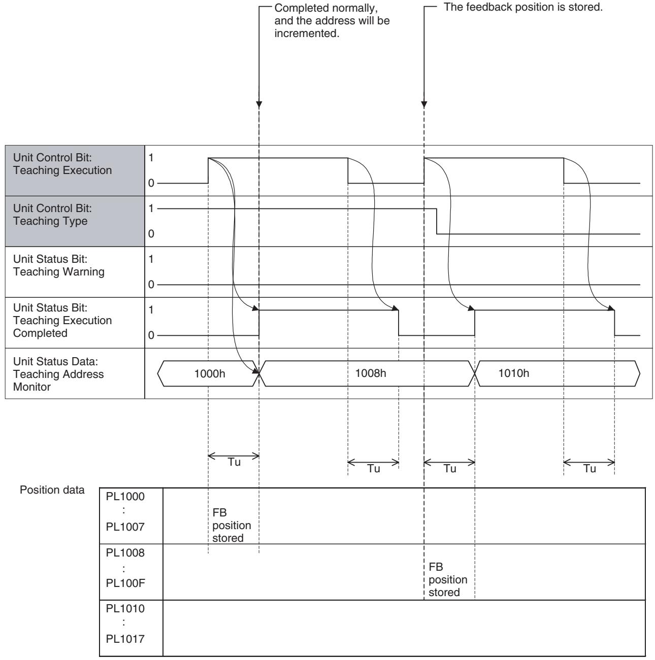
Teaching Execution (Normal completion):
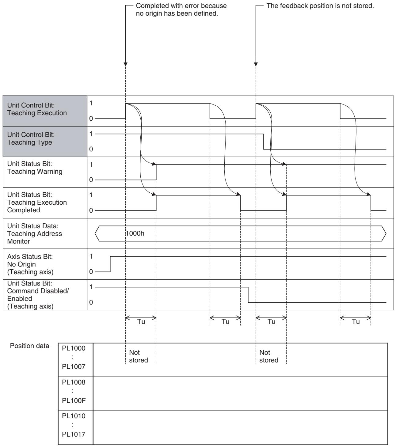
Teaching Execution (Error completion):
9-2 Debugging the Program
The debug function is described here, and the following functions are used for debugging the programs.
| Debug function | Debugged program | Operation | Debugging unit |
| Single Block Operation | Motion program | Ladder, the Support Tool | Motion task |
| Machine Lock | Motion program | Ladder, the Support Tool | Axis |
| Breakpoint | Motion program | The Support Tool | Motion task |
9-2-1 Single Block Operation
Function
- Single Block Operation is a motion program-debugging function that executes the motion program in block units so that program execution stops after each block.
- When the bit [Single Block Operation Mode] is ON, blocks not involving operations (program numbers or parallel branching labels) will be stopped.
Operation
- Single Block Operation can be executed by turning ON/OFF the bit [Single Block Operation Mode] from the ladder program or the Support Tool.
- Single Block Operation Mode will be started when the bit [Single Block Operation Mode] is turned ON. After a block is stopped, the next block can be executed by turning ON the bit [Motion Program Start].
- The bit [Start Mode] affects the bit [Motion Program Start] in the single block operation mode. Therefore, select Start Mode 2 to execute the program block by block.
| Start Mode | Behavior in the single block operation mode | Envisioned case |
| 0, 3 | Returns to the top of the program, and stops after executing the first line of the program. | Reconfirmation of a specified program |
| 1 | Executes the program from the top of the block currently being stopped, and stops at the end of the block. | Confirmation of a spec-ified program |
| 2 | Executes from the top of the next block, and stops at the end of the block. | Confirmation for indi-vidual block. |
Timing Chart
- The Unit checks ON/OFF of the bit [Single Block Operation Mode] between blocks, i.e. timing after end of the current block execution and before start of the next block execution.
- The same timing is used in Pass Mode. The program will be stopped at the end of the current block if the bit [Single Block Operation Mode] is ON before start of the next block execution. The program will not be stopped until the next block ends if execution of the next block has already started before the bit turns ON.
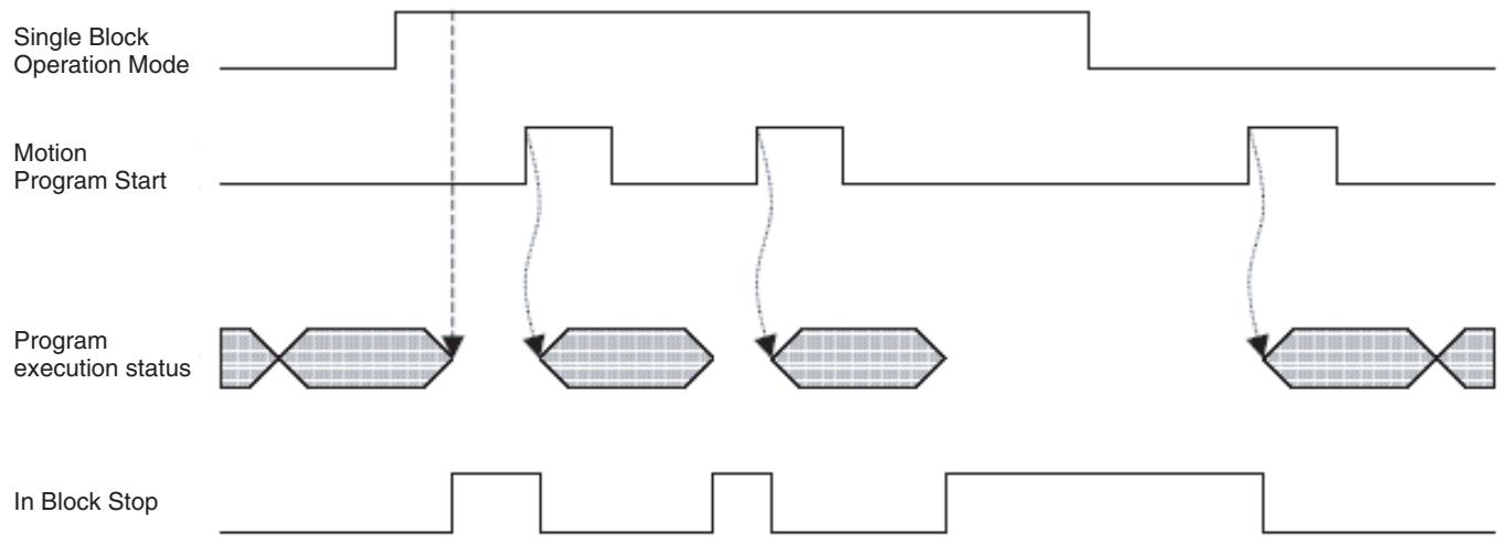
Effect on Other Tasks
Operation during Parallel Execution
Single Block Operation Mode is a function independent for each task, so there is no effect on other tasks.
If the bit [Single Block Operation Mode] is already ON before execution of parallel branching, each branch will be executed one block at a time. At the end (JWAIT command) of parallel execution, branches follow execution of the branch with the most blocks.
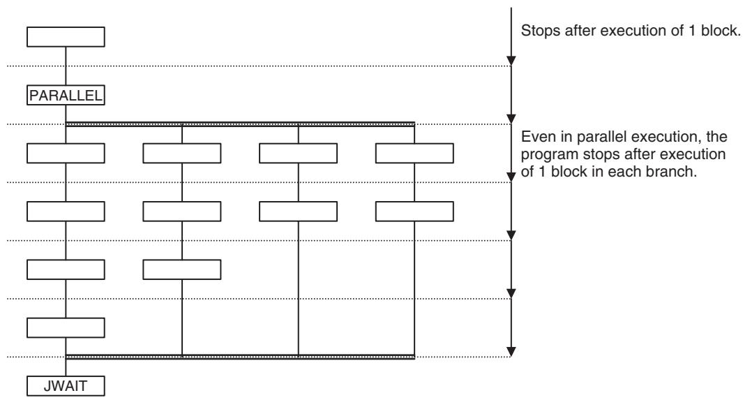
Single Block Ignored (NSTOP Command)
When the bit [Single Block Operation Mode] is turned ON during execution of parallel branching, all the branches will be stopped at the ends of the blocks currently being executed. When each block currently being executed in all the branches is stopped, the bit [In Block Stop] will be turned ON.
The block with NSTOP command in the motion program will ignore the Single Block Operation Mode. The Single Block Operation Mode will be ignored even when the bit [Single Block Operating Mode] is turned ON during execution of the block with NSTOP command, and execution will stop before the block without NSTOP command.
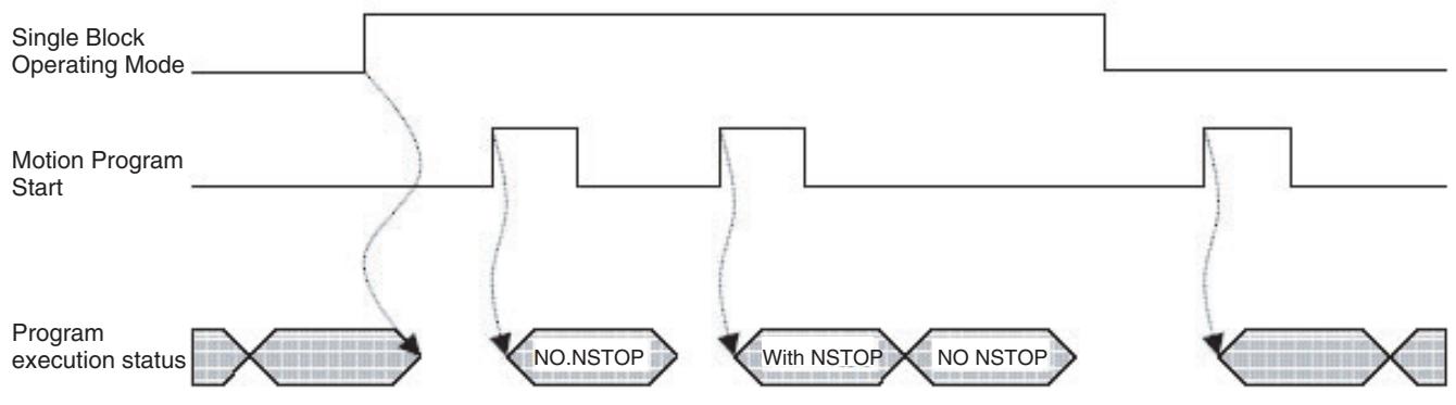
9-2-2 Machine Lock
Function
- Machine Lock function prohibits the output of movement commands to the axes so that operation sequences other than axis operations can be debugged.
- Though the output of movement commands to the axes is prohibited, calculations for the movement commands are executed and command position will be updated.
- Machine Lock can be used not only for debugging of the motion programs, but also for debugging of the ladder program in the CPU Unit.
- Signals to the output modules are output normally.
Operation
- Machine Lock can be executed by turning ON/OFF the bit [Machine Lock] from the ladder program or the Support Tool.
- When the Machine Lock status is cleared, the command position will be the one before the Machine Lock state.
Timing Chart
The bit [Axis Machine lock] will be checked on the timing when the bit [Axis Operating] is turned OFF, and the Machine Lock status will be changed accordingly.
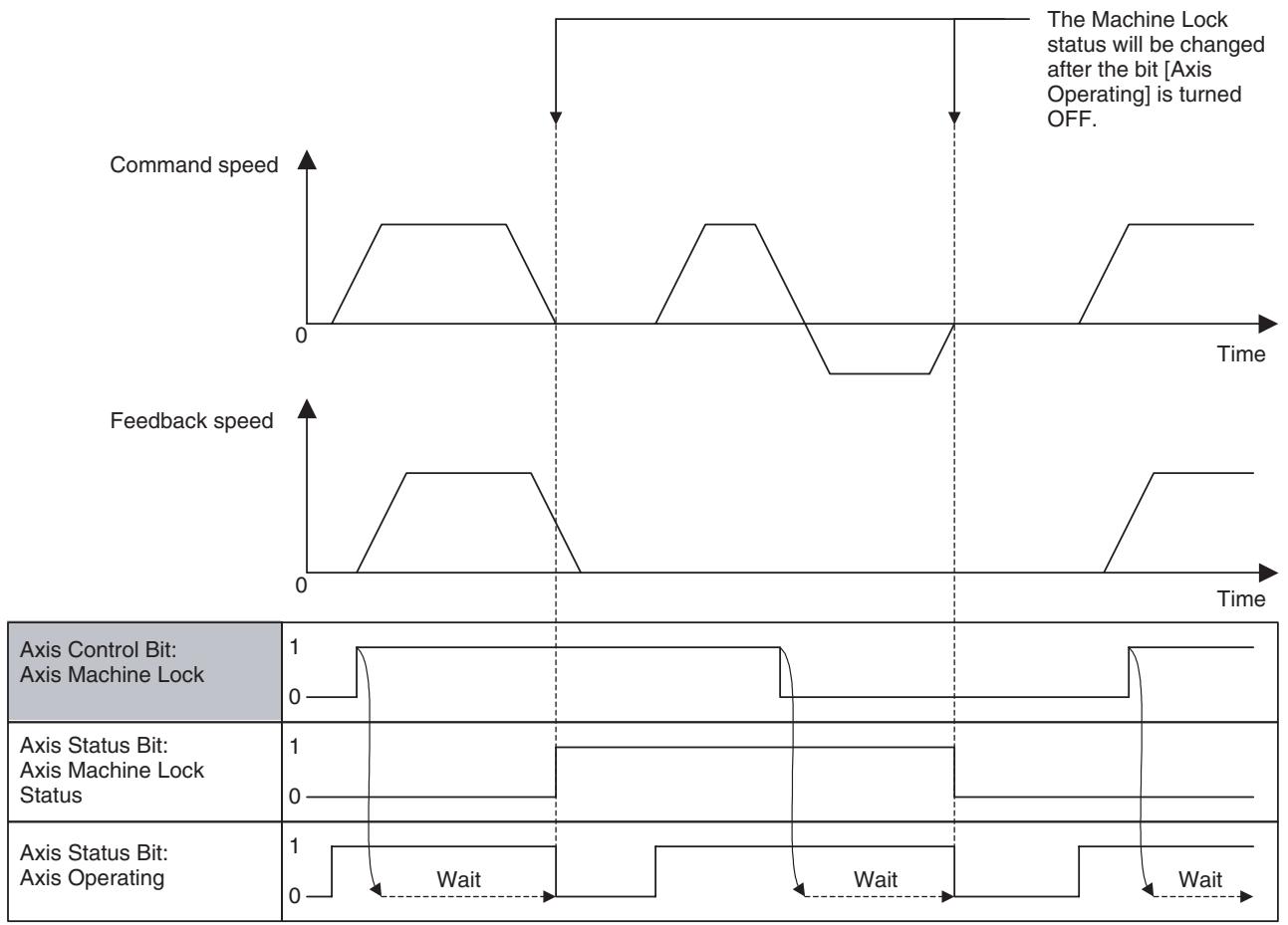
The bit [Axis Machine Lock Status] is not changed (turned ON/OFF). Due to the same reason, while the bit [Axis Machine Lock Status] is 1 (ON), commands are output not as Speed or Torque command, but as Position command. (This is because the present position is not managed in the control modes other than position control mode.)
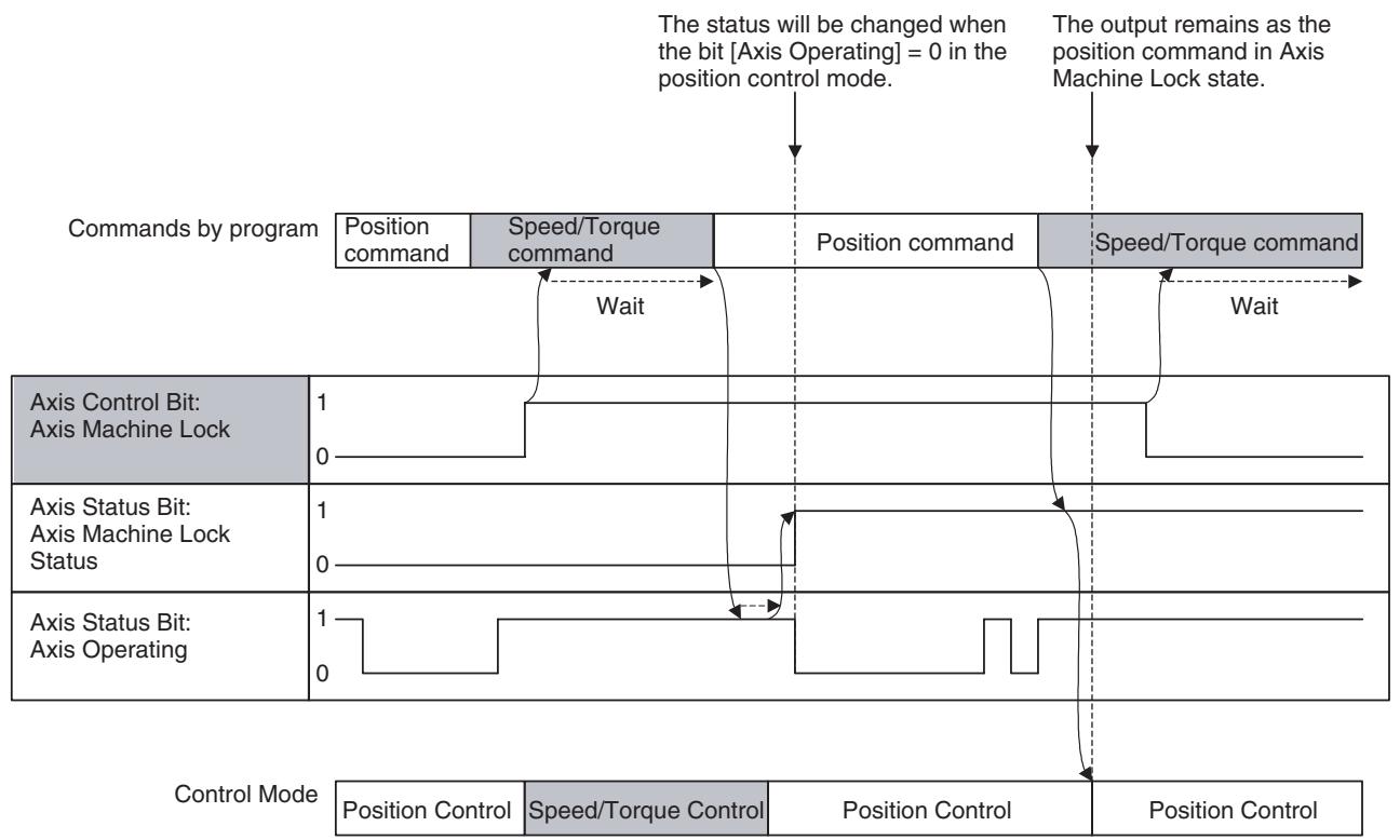
Effect
- Machine Lock is a function independent for each axis, so there is no effect of other axes.
When Machine Lock is executed on some of the axes (not on all the axes) during an operation involving several axes, the mechanical system may operate in an unexpected way. - In Machine Lock state, the origin search operation with DATUM command, Axis Control Bit: Origin Search will be the same as the operation of Axis Control Bit: Forced Origin. (This is to prevent the axis from moving endlessly. It is caused by the fact that the axis does not move at all in Machine Lock state and no external signal will be input.)
Operation during Parallel Execution
Regardless of parallel branching, Machine Lock status (set or reset) will be changed only in relation to the axis status.
Servo ON/OFF
Even in Machine Lock state, Servo ON of the concerned axis is required to move the axis.
Breakpoints
A breakpoint function is provided for MC Units with unit version 3.0 or later.
Function
- When a motion program is executed, program execution will be stopped after the commands in the specified block number have been executed.
- Breakpoints are set and cleared for block numbers using the Support Tool (CX-Motion-MCH version 2.0).
- One breakpoint can be set for one motion task.
Operation
- For details on setting and clearing breakpoints, refer to the Support Tool Operation Manual.
9-3 Coordinate System
9-3-1 Machine Coordinates and Workpiece Coordinates
There are two types of coordinate systems:
Machine coordinate system:
This is the coordinate system unique to the system that is determined by defining an origin.
- Workpiece coordinate system:
This is the coordinate system unique to the work that is determined by adding an offset to the machine coordinate system. There are 3 of them for each axis. The offset of the workpiece coordinate system is determined by executing OFFPOS command, and executing WORK command enables the workpiece coordinate system.
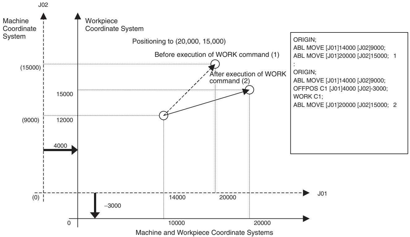
Basic Item
- The offset value (offset value set in OFFPOS command) is the data for each axis and motion programs or motion tasks do not influence it.
- The coordinate system select (coordinate system type or number set in ORIGIN or WORK command) is the data for each motion program and axes or motion tasks do not influence it.
When starting New Program Operation
When a new main program operation is started (the first execution after the power is turned ON or execution in Start Mode = 0 or 3), the machine coordinate system will be always used. The offset value of the previously executed program will be used, however, the coordinate system select will not be inherited to the new program.
When calling a Subprogram
- When a sub-program is called, the offset value and coordinate system select of the main program will be inherited to the sub-program.
- When returning to the main program from the sub-program, the coordinate system select will be inherited.
When Parallel Branching
- When executing parallel branching using PARALLEL command, the offset value and coordinate system select will be inherited to all the branches.
- The offset value and coordinate system select changed in a branch will influence other branches.
When executing the END Command
The offset value and coordinate system select will not be initialized at the point when the program is ended by END command.
9-3-2 Limited Length Axis and Unlimited Length Axis
Either of the two types of coordinate management can be used, which can be selected in the parameter [P5AA07: Axis feed mode].
- Limited length axis: Used for the axes with traveling limits such as XY tables.
- Unlimited length axis: Enables to control axes that move endlessly in one direction (turntable or conveyor). For unlimited feed axes, the range for updating the present position can be set as desired.
Limited Length Axis
- Upper limit of the limited axis = (P5AA04 × P5AA06 × LONGMAX)/(No. of encoder pulses × P5AA05)
- Lower limit of the limited axis = -(P5AA04 × P5AA06 × LONGMAX) / (No. of encoder pulses × P5AA05)
No. of encoder pulses: If the type of encoder is 16-bit, it is 65536 pulses/r (= 10000 Hex).
P5AA04: Command unit/1 machine rotation
P5AA05: Gear ratio 1 (Motor rotation speed)
P5AA06: Gear ratio 2 (Machine rotation speed)
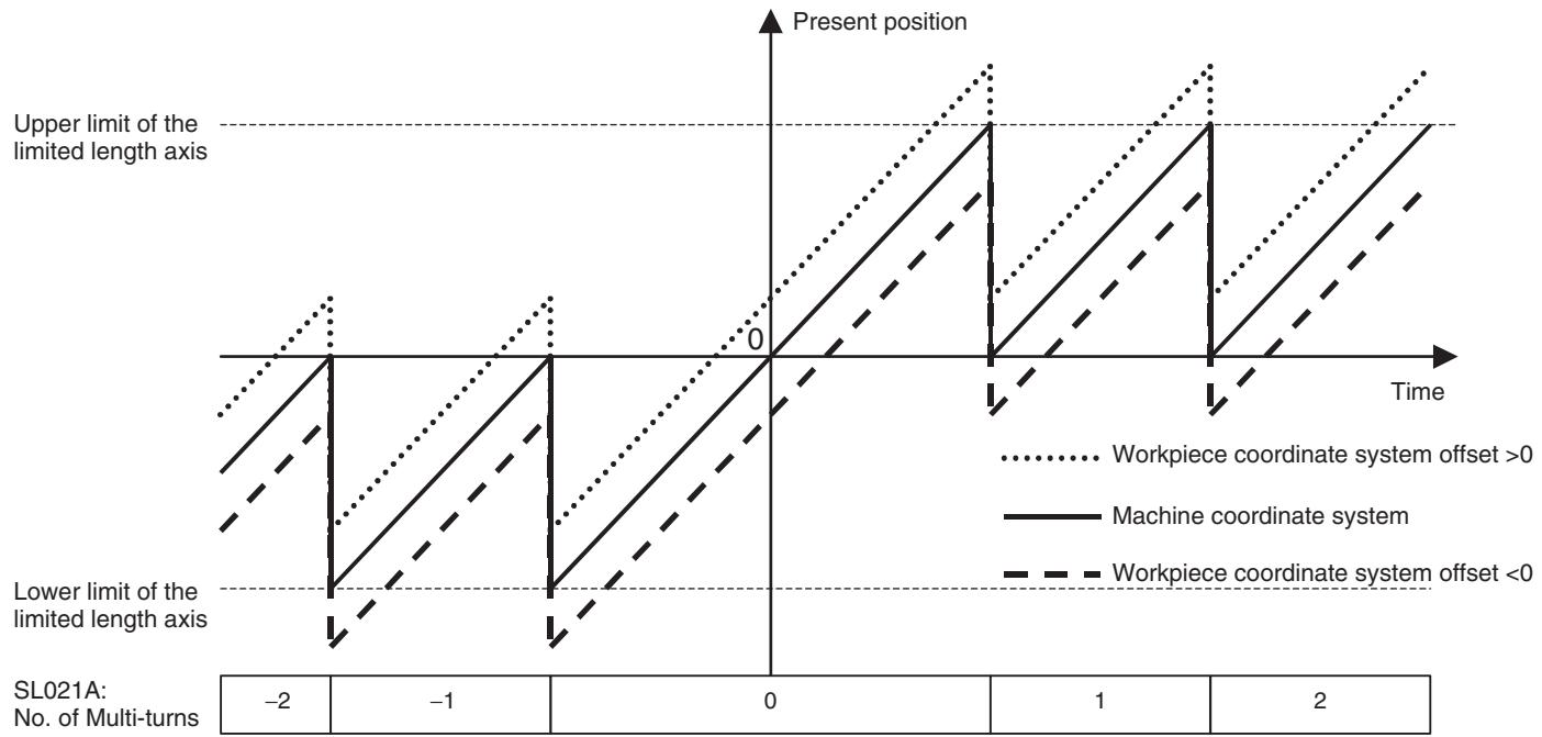
SL021A: No. of Multi-turns is a system variable that indicates the number of times of having exceeded the upper and lower limits of the Machine coordinate system. Unless SL021A: No. of Multi-turns is zero, the target position and the reached position will not match. Therefore, make sure to use the limited length axis within the range of the upper and lower limits.
Example:
Upper limit of the limited length axis = 100,000
Lower limit of the limited length axis = -100,000
SL0206: Machine coordinate system command position = -50,000
SL021A: No. of multi-turns = -1
When executing the following program with the setting above:
PROG P0001 Q00000001;
ABL MOVE [J01]50000;
END;
Travel distance = Target position - Present position = 50000 - (-50000) = 100,000
The present position and the number of multi-turns after the execution will be;
SL0206: Machine coordinate system command position = -50,000
SL021A: No. of Multi-turns = 0
The reached position is not equivalent to the target position (see the diagram below).
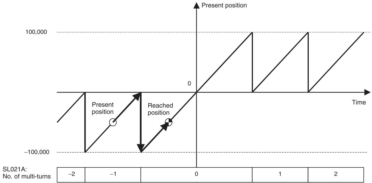
Unlimited Length Axis
- Upper limit of the unlimited length axis = P5AA04 - 1
- Lower limit of the unlimited length axis = 0
P5AA04: Command unit/1 machine rotation
With the unlimited length axis, even when SL021A: No. of multi-turns is not zero, the target position and reached position will match.
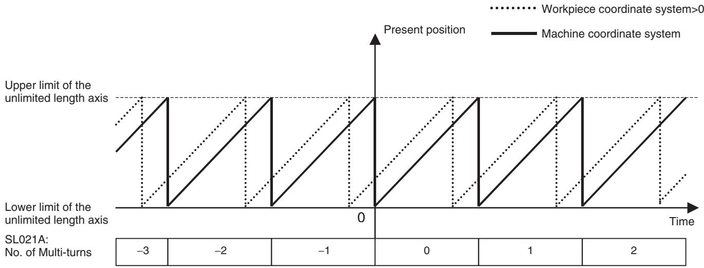
9-3-3 Software Limit
This is a function to provide software limit value on the coordinate system to prevent the machine from moving outside of the specified operating range. Normally, the limit value is set before the hardware limit sensor.
- Timing to detect the limit is only during axis movement (command output). It is not checked before operations.
- Before exceeding the limits, the following alarms will occur to stop the axis:
3005h: Positive direction software limit
- 3006h: Negative direction software limit
- The software limit function is not applicable for the unlimited length axis and the axis without an origin.
Related System Parameters
| No. | Name | Range | Unit | Description |
| P3AA02 | Positive direction software limit | -2147483648~2147483647 | Command unit | Limit value of the positive direction software limit |
| P3AA03 | Negative direction software limit | -2147483648-2147483647 | Command unit | Limit value of the negative direction software limit |
| P3AA04 | Software limit enabled/ disabled | 0: Both + and - software limits disabled1: Only + software limit enabled2: Only – software limit enabled3: Both + and – software limits enabled. | --- | Software limit enable/disable |
Software Limit Range
| Specification | Operation (Shaded area is the operating range.) | ||
| P3AA04 = 0 | The entire area is the operating range. | ||
| P3AA03 | P3AA02 | ||
| P3AA04 = 1 | Lower than [P3AA02: + direction software limit] is the operating range. | ||
| P3AA03 | P3AA02 | ||
| → | |||
| P3AA04 = 2 | Higher than [P3AA03: – direction software limit] is the operating range.P3AA03 | P3AA02 | |
| ← | |||
| P3AA04 = 3P3AA03 < P3AA02 | The area between [P3AA03] and [P3AA02] is the operating range.P3AA03 | P3AA02 | |
| ← | → | ||
| P3AA04 = 3P3AA03 = P3AA02 | The entire area is the operating range.P3AA02 = P3AA03 | ||
| P3AA04 = 3P3AA03 > P3AA02 | The entire area is the operating range.P3AA02 | P3AA03 | |
Note Meaning of arrows.
: The alarm [3005h: Positive direction software limit] occurs.
: The alarm [3006h: Negative direction software limit] occurs.
9-3-4 Absolute Value Detection Function
Relation Between Coordinate System and Absolute Value Detection Function
Using as Limited Length Axis
- The absolute encoder stores the multi-turn data in the internal battery backup memory. Therefore, the origin on the coordinate system can be defined without executing an origin search after the power is turned ON.
- In the MC Unit, when the bit [ABS Origin Setting] is turned ON, the relations between the absolute data read from the absolute encoder when communications were established and the coordinate system managed in the Unit will be saved in the Flash memory.
- When using an axis as the limited length axis, make sure to operate the axis within the range where the multi-turn data is not reset.
- When the servo parameter [Pn205: Multi-turn limit setting] is 65535 (default setting), the multi-turn data will change as shown below:
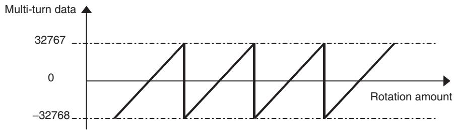
-
There will be no problem if the axis is used within the range where the multi-turn data is between -32768 to 32767. However, if the power is turned OFF once, and ON again when the axis is outside of the range, the present position cannot be read correctly. No alarm will occur.
-
If origin setting is executed near the limit of the multi-turn data, a slight movement will make the axis exceed the limit. Therefore, always initialize the multi-turn data of the encoder before executing origin setting.
- The operation that the axis is used within the ranges where the multi-turn data is reset or not reset is shown below:
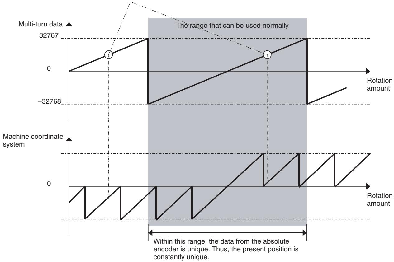
Using as Unlimited Length Axis
Same as the case of limited length axis, to execute the axis operation within the range where the multi-turn data is not reset, use the same setting as the one for the limited length axis. However, to execute the axis operation exceeding the limit of the multi-turn data, it is required to match the reset timing of the coordinate system managed in the MC Unit and the reset timing of the encoder's multi-turn data. To match the timings appropriately, adjust the setting value of the parameter [Pn205: Multi-turn limit setting]. In the case where the load shaft makes n rotations while the motor makes m rotations, set the value obtained by subtracting 1 from the denominator of deceleration ratio (m-1) in Servo Driver parameter Pn205.
Also set the following MC Unit parameters:
P5AA06: n
P5AA05: m
Motor parameter 900C: m-1
If the value other than 65535 is set in the servo parameter [Pn205: Multi-turn limit setting], the multi-turn data will change as shown below:
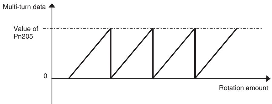
When Multi-turn Limit Setting Is Adjusted
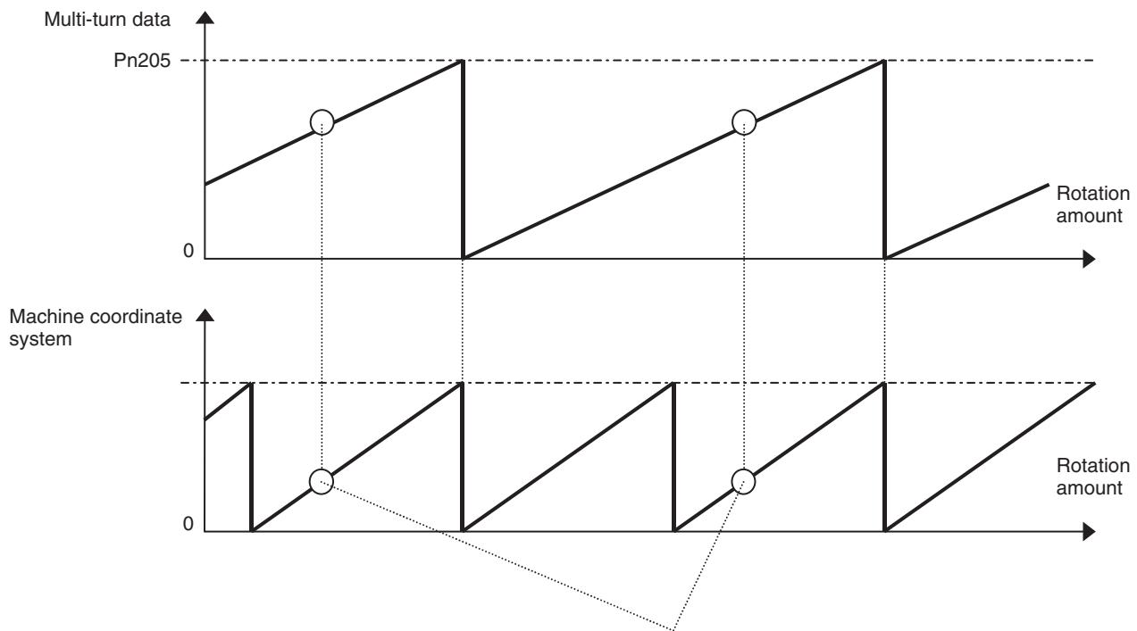
The same present value can be obtained from the same multi-turn data.
Note that, however, there is no guarantee on the value of the number of multi-turns (SL021A: Number of multi-turns) on the machine coordinate system.
When Multi-turn Limit Setting is not Adjusted
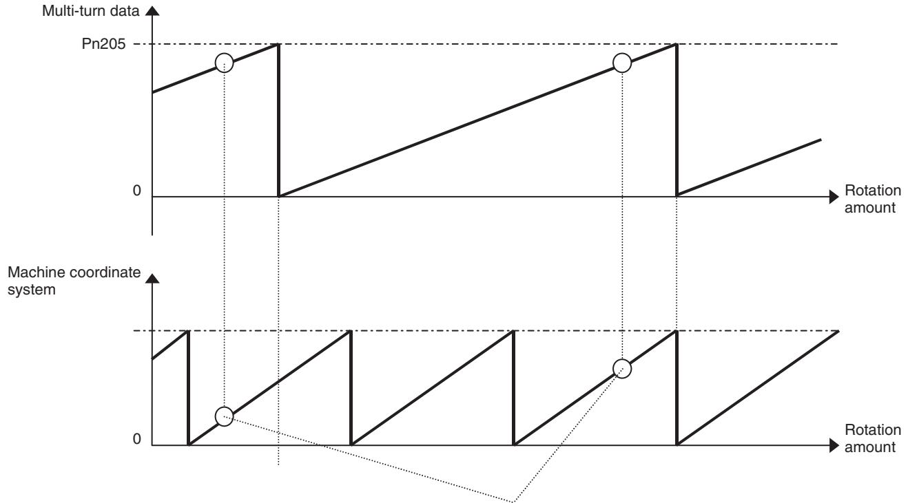
The same present value cannot be obtained from the same multi-turn data.
Similar to the case above, the correct present value cannot be obtained when the reset cycle of the multi-turn data is shorter than the cycle of the machine coordinates system.
When Multi-turn Reset Cycle is Shorter than Machine Coordinate System Cycle
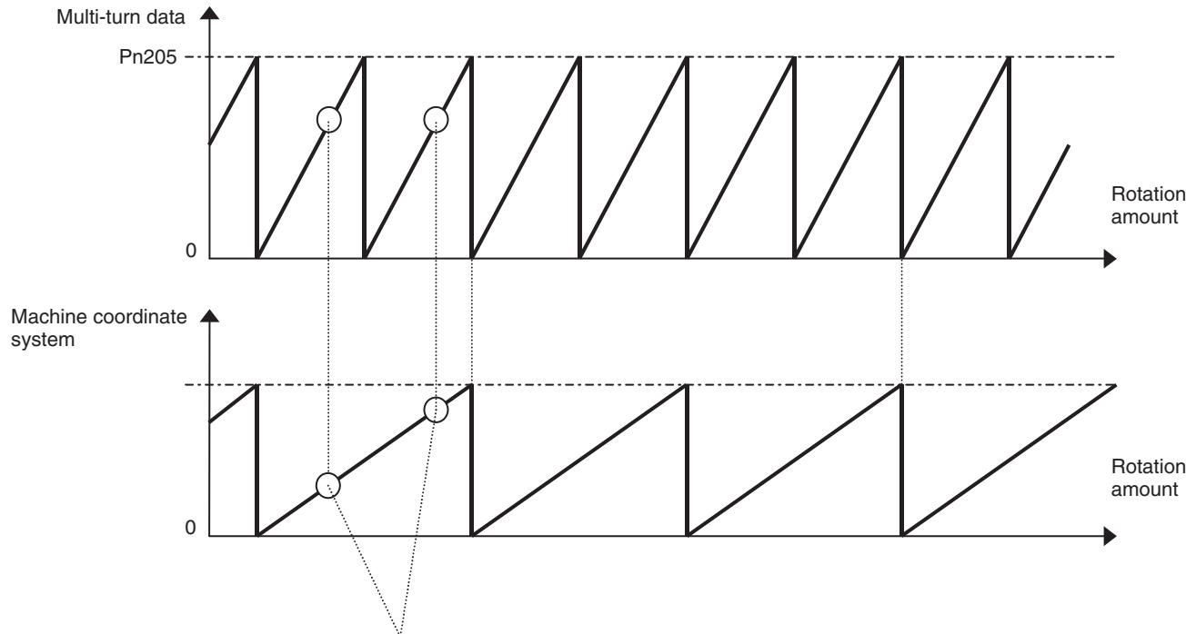
The same present value cannot be obtained from the same multi-turn data.
9-4 Backup and Restore Function
When replacing the Unit, etc., all the data in the MC Unit can be saved in the memory card of the CPU Unit at once. The saved settings can be set in another MC Unit using the memory card easily. For details, refer to the applicable CPU Unit operation manual.
- Backup: Flash memory of MC Unit Memory Card of CPU
- Restore: Memory Card of CPU Flash memory of MC Unit (After restore, the power has to be turned OFF once and ON again, or the Unit has to be reset.)
- Verify: Memory Card of CPU Flash memory in MC Unit (Verify is executed by the CPU Unit, and thus it functions as the backup for the MC Unit.
- The Memory Card capacity required to back up the data from one MC Unit is 4 MB max.
If data from the CPU Unit is also to be backed up, we recommend Memory Cards with even larger capacities.
Applicable Data
| Data | Remark |
| Unit model, Version info | |
| Motion programs | Including text and analysis, internal management data |
| CAM data | Including internal management data |
| System parameters | |
| Servo parameters | Including servo reading parameters |
| Position data | |
| ABS origin position data | |
| Origin compensation value (Unit Ver. 3.1 and later) | The origin compensation value when an absolute encoder is being used can be backed up by using the IOWR/IORD instructions in the CPU Unit. For unit versions 3.1 and later it can be backed up using the Support Software. |
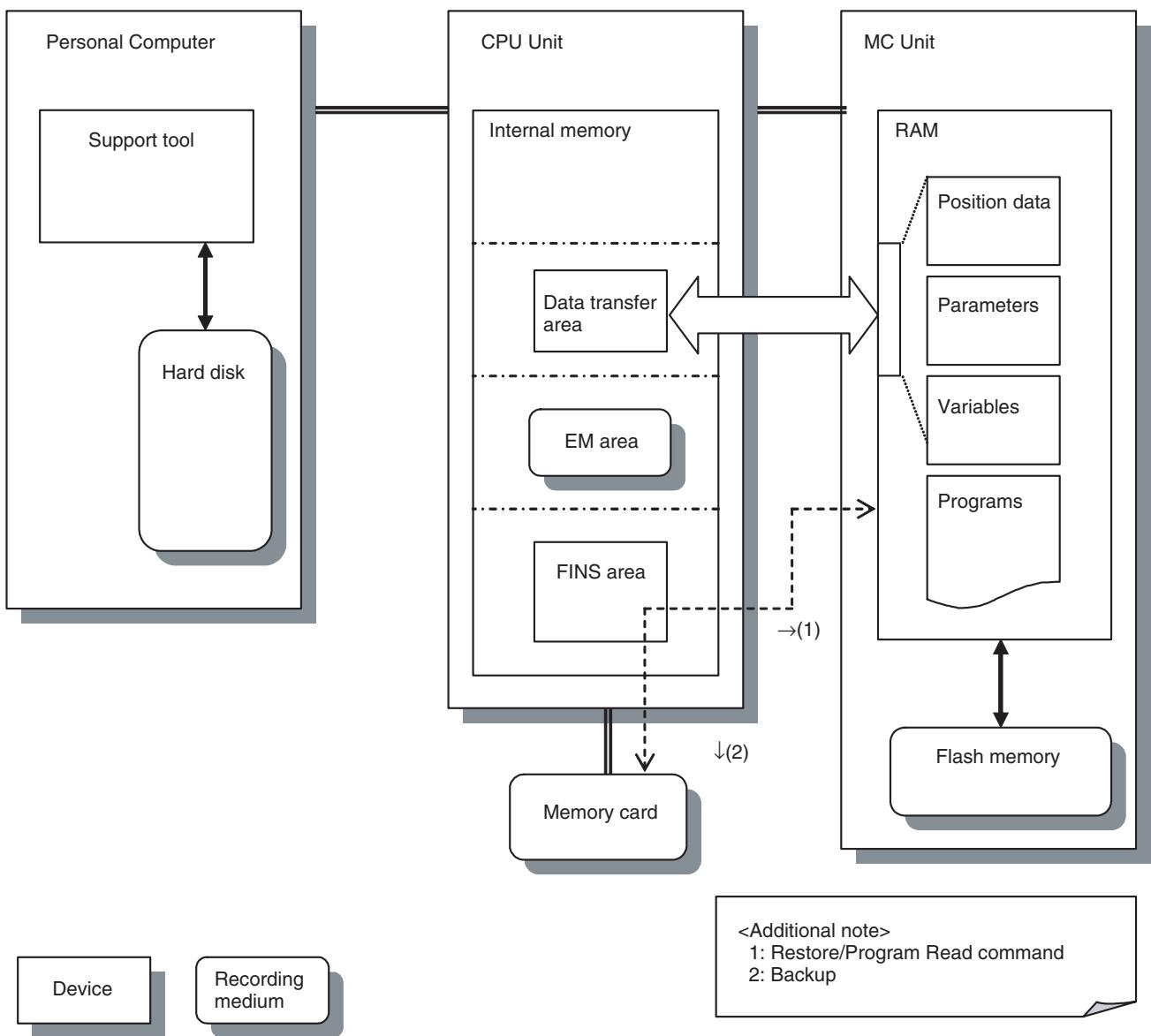
9-4-1 Procedures for Backup and Restore
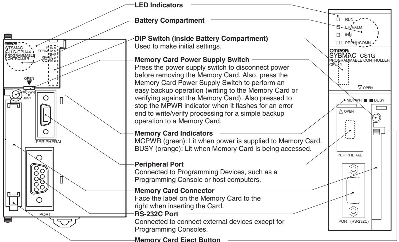
Press the eject button to remove the Memory Card from the CPU Unit.
Backup Method
1,2,3... 1. Insert the memory card and switch ON. (MCPWR LED on the CPU Unit front panel is lit.)
2. Turn ON the DIP switch SW7 on the front panel.
3. Press down the memory card power-dispatch stop button at least for 3 seconds.
BUSY-LED is lit and writing to the memory card starts.
(During the execution, the auxiliary bit [A34313: File Memory Operation Flag] is turned ON.)
- Backup will be completed when MCPWR/BUSY-LED is turned OFF. (Backup execution time is about 7 to 8 minutes.)
Restore Method
1,2,3... 1. Turn ON the DIP switch SW7 on the CPU Unit front panel.
- Insert the memory card and switch ON. MCPWR/BUSY-LED on the CPU Unit front panel is lit and reading from the memory card starts. (During the execution, none of the LED indicators on the MC Unit is lit.)
- The execution will be completed when MCPWR/BUSY-LED is turned OFF. (The restore execution time is about 4 to 5 minutes.)
- After completion, switch OFF the CPU Unit once. Then, turn OFF the DIP switch SW7. Finally, switch ON the CPU Unit again. (The MC Unit will not start without this operation.)
Note For details, refer to 5-2-6 Simple Backup Function in SYSMAC CS/CJ Series Programmable Controllers Programming Manual (W394).
9-5 Servo Driver Status Output
The Servo Driver status output function is supported by MC Units with unit version 3.0 or later.
Status Output Function
The codes that are generated together with the main circuit ON/OFF and other Servo Driver statuses that occur for each axis when a Servo Driver warning/alarm occurs are collected and continuously set in the output variables.
Allocating this output variable area in the CPU Unit and general-purpose I/O area makes simultaneous monitoring of multiple axes easy.
Status Output Methods
The statuses for the Servo Driver are output each Unit Cycle in variables OW0210 to OW026F as shown in the following table.
| Address | Name | Details |
| OW0210 | Axis 1 Warning code/ alarm code | If an alarm or warning occurs in the MECHATROLINK-II slave, the alarm/warning code is stored. This code is set to 0 when the axis alarm reset bit for each axis is turned ON. |
| OW0211 | Axis 1 Status (1) | The same value as Servo status SW021C is stored. The value is refreshed every Unit Cycle. |
| OW0212 | Axis 1 Status (2) | The same value as Servo status SW021D is stored. The value is refreshed every Unit Cycle. |
| to | to | --- |
| OW026D | Axis 32 Warning code/ alarm code | If an alarm or warning occurs in the MECHATROLINK-II slave, the alarm/warning code is stored. This code is set to 0 when the axis alarm reset bit for each axis is turned ON. |
| OW026E | Axis 32 Status (1) | The same value as Servo status SW021C is stored. The value is refreshed every Unit Cycle. |
| OW026F | Axis 32 Status (2) | The same value as Servo status SW021D is stored. The value is refreshed every Unit Cycle. |
9-6 Data Tracing
Data Tracing Operations
Data tracing is supported for MC Units with unit version 3.0 or later.
The following table lists the data trace operations that are supported for MC Units.
| Item | Description |
| Number of trace groups | 2 |
| Number of trace data items | From 1 to 16 items can be simultaneously collected per group.A maximum total of 32 items can be simultaneously collected for two groups combined.Note Bit information (e.g., JOG bit s) or monitoring information (e.g., present positions) is counted as one item. |
| Number of trace points | From 2,048 (for 1 trace data item) to 32,768 trace points (for 16 trace data items) can be collected per group. |
| Trace execution scan | The specified data is collected each Unit cycle.If the Unit cycle is 1 ms, data can be collected for a maximum of 32,768 ms. |
| Trace data format | Bits, words, double words, and real numbers |
| Trace start | The trace start condition can be set using the Support Tool. |
| Trigger condition | The trigger condition can be set as a single condition or as two conditions with a logical AND.Data: = ≠ < > ≤ ≥Bit: ON, OFF, leading edge, trailing edge |
| Pre-trigger | Data prior to the trigger condition can be traced. |
| Saving trace conditions | The conditions to be traced can be saved in flash memory. |
Details of Operations
For details on operation methods, refer to the CX-Motion-MCH Support Tool Operation Manual.
9-7 Zones
Overview
Zones are supported for MC Units with unit version 3.0 or later.
A zone bit turns ON when a specified variable is within the set range, and turns OFF when the variable is outside of the range.
A maximum of 32 zone bits can be set.
Using Zones
Perform the following operations to use zones.
- Set the following system parameters:
(1) Set the number of zone bits to be used.
(2) Set the leading address of the area where the zone upper and lower limits are to be set.
(3) Set the variable types and addresses of the variables that are to be monitored.
(4) Set the output variable addresses and bit numbers for where the monitoring results (ON/OFF) are to be output. - Set the zone upper and lower limits from the motion program or the CPU Unit.
- Enable or disable the zone bits from the motion program or the CPU Unit.
Setting System Parameters
As shown in the following diagram, set the two Unit parameters and the two zone parameters for each axis.
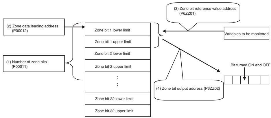
Setting Upper and Lower Limits for Zone Bits
Set the upper and lower limits for each zone bit from the address specified in P00012.
To make the setting from a motion program, substitute the upper and lower limits for this address.
If the position data area is specified in P00012, the setting can also be made using the Support Tool. In this case, the zone bit upper and lower limits can be saved in flash memory.
To make the setting from the CPU Unit, allocate this area as a general-purpose I/O area or use the IOWR instruction.
Enabling and Disabling Zone Bits
Each zone bit can be enabled or disabled by turning ON or OFF the applicable bits for the following variables.
| Address | Name | Contents |
| IW0304 | Zone enable bits (No. 1 to 16) | Enables or disables zone bits No. 1 to 16. No. 1 corresponds to bit 0, and No. 16 corresponds to bit 15. 0: Disable (Do not use) 1: Enable (Use) |
| IW0305 | Zone enable bits (No. 17 to 32) | Enables or disables zone bits No. 17 to 32. No. 17 corresponds to bit 0, and No. 32 corresponds to bit 15. 0: Disable (Do not use) 1: Enable (Use) |
The following output variables can be used to check whether a zone bit is enabled or disabled.
| Address | Name | Contents |
| OW0304 | Zone monitoring status bits (No. 1 to 16) | Used to output the enabled/disabled status of zone bits No. 1 to 16. No. 1 corresponds to bit 0, and No. 16 corresponds to bit 15. 0: The setting for the zone upper and lower limits is incorrect, or the zone enable bit is OFF (disabled). 1: The setting for the zone upper and lower limits is correct and the zone enable bit is ON (enabled). |
| OW0305 | Zone monitoring status bits (No. 17 to 32) | Used to output the enabled/disabled status of zone bits No. 17 to 32. No. 17 corresponds to bit 0, and No. 32 corresponds to bit 15. 0: The setting for the zone upper and lower limits is incorrect, or the zone enable bit is OFF (disabled). 1: The setting for the zone upper and lower limits is correct and the zone enable bit is ON (enabled). |
SECTION 10
Program Example
The section provides a programming example to demonstrate how the CJ1W-MCH71 and CS1W-MCH71 Motion Control Units can be used.
10-1 Program Example 574
10-1-1 Positioning with PTP Control 574
10-1-2 Positioning with Linear Interpolation 575
10-1-3 Positioning with Linear and Circular Interpolation. 576
10-1-4 Positioning with Position Data 577
10-1-5 Positioning with Workpiece Coordinate System with Subprograms 578
10-1-6 Positioning with Changing Interpolation Acceleration Time Parameter 580
10-1-7 Positioning with Position Data Calculation 581
10-1-8 Stopping a Program with General Input 583
10-1-9 Stopping Operation with Optional End Using General Input and Assigning Position Data 583
10-1-10 Positioning of Turntable 584
10-1-11 Feeder Feeding 586
10-1-12 Starting Peripherals during Axis Movement. 587
10-1-13 High-speed Positioning 588
10-1-14 Interrupt Feeding (MOVEI) 589
10-1-15 Time-specified Positioning (MOVET) 590
10-1-16 Regular Winding to Rough Winding (MOVETRAV) 591
10-1-17 Electronic Cam, Single Axis (CAM) 592
10-1-18 Link Operation (MOVELINK) 594
10-1-19 Electronic Cam, Synchronous (CAMBOX) 595
10-1-20 Electronic Shaft (CONNECT) 596
10-1-21 Trailing Synchronization/Synchronization Cancel (SYNC/SYNCR) 597
10-1-22 Travel Distance Superimpose/Travel Distance Superimpose Cancel (ADDAX/ADDAXR) 598
10-1-23 Speed Control/Speed Control Cancel (SPEED/SPEEDR) 600
10-1-24 Torque Control/Torque Control Cancel (TORQUE/TORQUER) 601
10-1-25 Target Position Change (MOVEMODI) 602
10-1-26 Present Position Latch (LATCH) 603
10-1-27 Single Block Ignored (NSTOP) 604
10-1-28 Parallel Execution (PARALLEL, JOINT, JWAIT) 605
10-1-29 Selective Execution (SWITCH, CASE, BREAK, SEND) 606
10-2 Slave Modules 607
10-2-1 Using 64-Point I/O Module. 607
10-2-2 Using Counter Module 608
10-2-3 Using Pulse Output Module 612
10-3 Others. 619
10-1 Program Example
This section shows several motion programs for different typical application.
10-1-1 Positioning with PTP Control
| Explanation of the operation | ·Positioning to the 3 points below is executed with PTP control, and the axes returns to the origin ([J01]0, [J02]0). ·When positioning is completed, 1 will be output to CPU unit using the general I/O area. |
| 1,2,3... | 1. [J01]10000, [J02]50000 1 is output to the general output (0BA0). ↓ |
| 2. [J01]50000, [J02]75000 ↓ | |
| 3. [J01]100000, [J02]100000 1 is output to the general output (0BA1). ↓ | |
| 4. [J01]0, [J02]0 | |
| Program | The numbers 01) to 15) are used only for the sake of explanation. They are not needed in programming. |
| 01) PROG P001 Q00000003; | |
| 02) MOVE [J01]10000 [J02]50000; | |
| 03) NOPS; | |
| 04) #OW0BA0 = 1; | |
| 05) WAIT #IW0B00 = = 1; | |
| 06) #OW0BA0 = 0; | |
| 07) MOVE [J01]50000 [J02]75000; | |
| 08) DWELL T300; | |
| 09) MOVE [J01]100000 [J02]100000; | |
| 10) NOPS; | |
| 11) #OW0BA1 = 1; | |
| 12) MOVE [J01]0 [J02]0; | |
| 13) NOPS; | |
| 14) #OW0BA1 = 0; | |
| 15) END; | |
| Explanation of the program | 01) A program No. and axes to be used are specified. |
| 02) Positioning to [J01]10000, [J02]50000 with PTP control is performed. | |
| 03) NOPS command will hold the program advance till positioning 02) is completed (within in-position range). | |
| 04) Once positioning is completed, 1 will be output to the general output (OW0BA0). | |
| 05) The program advance will be held till the general input (IW0B00) becomes 1. | |
| 06) The program will advance to the next block after the general output from 04) is cleared. | |
| 07) Positioning to [J01]50000, [J02]75000 with PTP control is performed. | |
| 08) The program waits for 3 seconds. | |
| 09) Positioning to [J01]100000, [J02]100000 with PTP control is performed. | |
| 10) to 14) 1 will be output to the general output (OW0BA1) after positioning is completed and the axes will return to the origin. Once they reach the origin, the general output (OW0BA1) will be reset. |
15) The program is completed.
10-1-2 Positioning with Linear Interpolation
Explanation of the operation
- At the rise of the general input (IW0B00), positioning with linear interpolation is performed from the present position to the position [J01]10000, [J02]50000.
- The positioning will be repeated up to 10 times till the content of the general input (IW0B01) becomes 1.
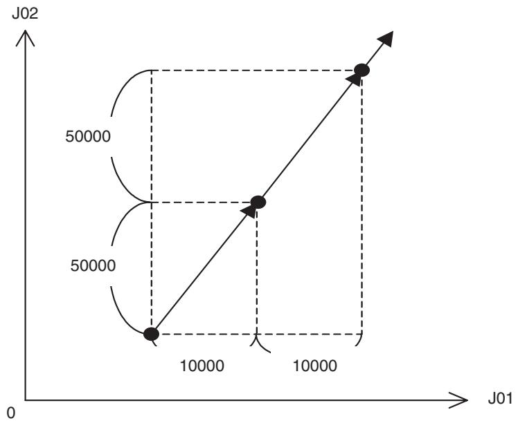
Program
Explanation of the program
01) A program No. and axes to be used are specified.
02) With FOR (Repeat) command, the process through 02) to 07) is repeated 10 times.
03) When the general input (IW0B00) is not 1, the program executes the axis operation. When it is 1, the program advances to the next block without any axis operation.
04) The program will wait until the general input (IW0B01) becomes 1.
05) Positioning with linear interpolation is performed from the present position to the position [J01]10000, [J02]50000.
06) This is the end of IF command from 03).
07) This is the end of FOR command from 02).
08) The program is completed.
10-1-3 Positioning with Linear and Circular Interpolation
Explanation of the operation
Positioning with the path shown below is performed combining linear and circular interpolation.
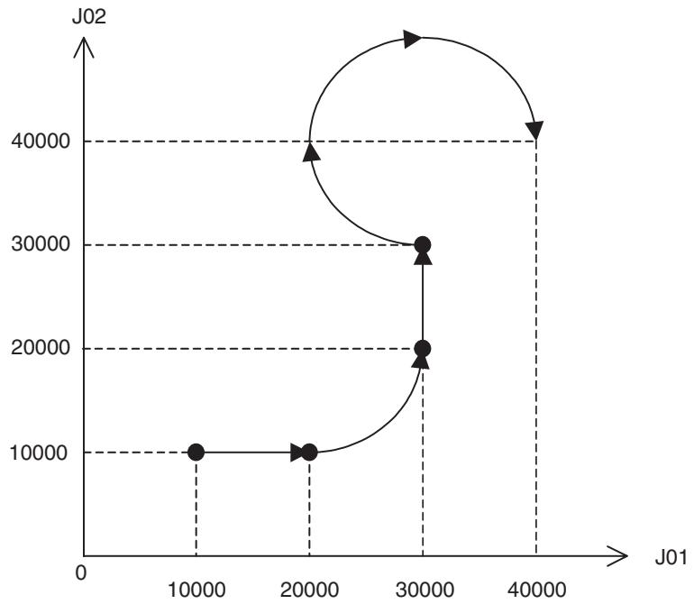
Program
01) PROG P003 Q00000003;
02) PASSMODE;
03) MOVEL [J01]20000 [J02]10000 F300000;
04) MOVEC Q-1 [J01]30000 [J02]20000 R10000;
05) MOVEL [J02]30000;
06) MOVEC Q1 [J01]40000 [J02]40000 I0 J10000;
07) END;
Explanation of the program
01) A program No. and axes to be used are specified.
02) Pass Mode is selected.
03) The axes move to the position [J01]20000, [J02]10000 with linear interpolation.
04) The axes move in CCW direction to the position [J01]30000, [J02]20000 with circular interpolation of radius "10000". (Since a positive value is specified for radius, the center angle is smaller than 180 degrees (a quarter of the circle).)
05) The axes move to the position [J01]30000, [J02]30000 with linear interpolation.
06) The axes move in CW direction to the position [J01]40000, [J02]40000 with circular interpolation having the position [J01]30000, [J02]40000 as its center.
07) The program is completed.
10-1-4 Positioning with Position Data
Explanation of the operation
Positioning is performed using indirectly specified position data.
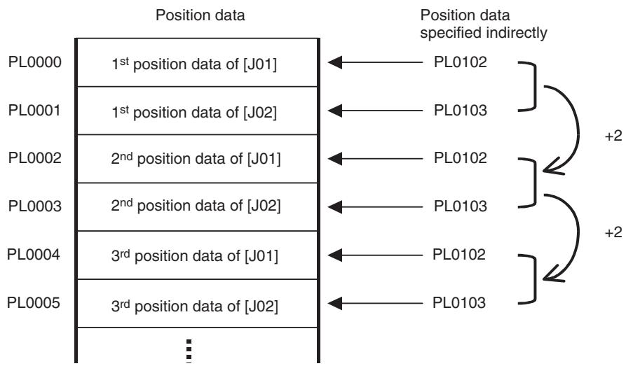
Program
Explanation of the program
01) A program No. and axes to be used are specified.
02) Stop Mode is selected.
03) The task variable for counting (ML0000) is reset.
04) The position data (PL0102) is set to 0. (The first position data read with indirect specification)
05) The position data (PL0103) is set to 1. (The first position data read with indirect specification)
06) The process through 06) to 13) is repeated 3 times.
07) The position data (PL0102) is assigned to the position data (PL0100).
08) The position data (PL0103) is assigned to the position data (PL0101).
09) When the general input (IW0B00) is not 0, the program advances to the next block without any axis operation.
10) Positioning with linear interpolation is performed reading the position data with indirect specification.
11) This is the end of IF command from 09).
12) The content of the position data (PL0102) is updated.
13) The content of the position data (PL0103) is updated.
14) This is the end of FOR command from 06).
15) The program is completed.
10-1-5 Positioning with Workpiece Coordinate System with Subprograms
Explanation of the operation
Changing coordinate systems and using subprograms, the same operation is executed repeatedly in different positions on the machine coordinate system.
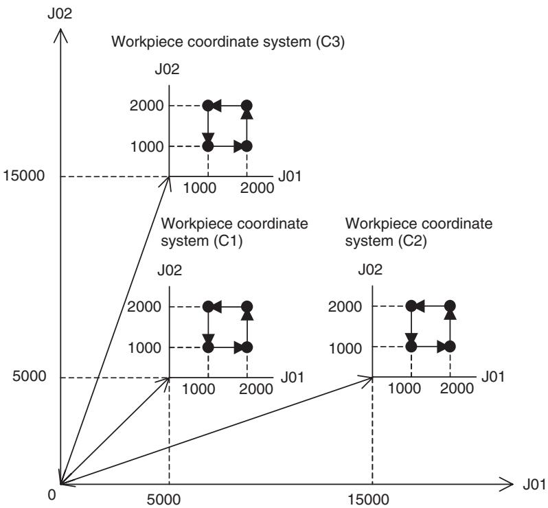
Program
Main program
01) PROG P005 Q00000003;
02) OFFPOS C1 [J01]5000 [J02]5000;
03) OFFPOS C2 [J01]15000 [J02]5000;
04) OFFPOS C3 [J01]5000 [J02]15000;
05) MOVEL [J01]0 [J02]0 F300000;
06) WORK C1;
07) GOSUB P500;
08) ORIGIN;
09) MOVEL [J01]0 [J02]0 F500000;
10) NOPS;
11) #OW0BA0 = 1;
12) WAIT #IW0B00 = = 1;
13) #OW0BA0 = 0;
14) WORK C2;
15) GOSUB P500;
16) ORIGIN;
17) MOVEL [J01]0 [J02]0 F500000;
18) NOPS;
19) #OW0BA0 = 1;
20)WAIT #IW0B00 = = 1;
21) #OW0BA0 = 0;
Explanation of the program
01) A program No. and axes to be used are specified.
02) to 04) Offset values for workpiece coordinate systems C1 to C3 are changed.
05) The axes move from the present position to the origin on the machine coordinate system.
06) The coordinate system is switched from the machine coordinate to the workpiece coordinate C1.
07) The subprogram (P0500) is called and executed.
08) The coordinate system is switched back to the machine coordinate.
09) The axes return to the origin on the machine coordinate system.
10) to 13) After return to the origin, 1 is output to the general output (OW0BA0) and the program will wait until the general input (IW0B00) becomes 1. Once the general input (IW0B00) becomes 1, the general output (OW0BA0) will be reset, and the program will advance to the next block.
14) The coordinate system is switched from the machine coordinate to the workpiece coordinate C2.
15) The subprogram (P0500) is called and executed.
16) The coordinate system is switched back to the machine coordinate.
17) The axes return to the origin on the machine coordinate system.
18) to 21) After return to the origin, 1 is output to the general output (OW0BA0) and the program will wait until the general input (IW0B00) becomes 1. Once the general input (IW0B00) becomes 1, the general output (OW0BA0) will be reset, and the program will advance to the next block.
22) The coordinate system is switched from the machine coordinate to the workpiece coordinate C3.
23) The subprogram (P0500) is called and executed.
24) The coordinate system is switched back to the machine coordinate.
25) The axes return to the origin on the machine coordinate system.
26) The program is completed.
Subprogram
01) A subprogram No. and axes to be used are specified.
02) The axes move from the present position to the position [J01]0, [J02]0.
03) The axes move to the position [J01]1000, [J02]1000.
04) The axis moves to the position [J01]2000.
05) The axis moves to the position [J02]2000.
06) The axis moves to the position [J01]1000.
07) The axis moves to the position [J02]1000.
08) The axes move to the position [J01]0, [J02]0.
09) The subprogram is completed and the main program is resumed.
10-1-6 Positioning with Changing Interpolation Acceleration Time Parameter
| Explanation of the operation | Positioning with linear interpolation is performed while changing the interpolation acceleration time parameter. |
| Program | 01) PROG P006 Q00000003;02) PARAM P00102 = 1000;03) MOVEL [J01]10000 [J02]5000 F500000;04) MOVEL [J01]20000 [J02]-10000;05) NOPS;06) #OW0BA0 = 1;07) WAIT #IW0B00 = = 1;08) #OW0BA0 = 0;09) PARAM P00102 = 100;10) MOVEL [J01]30000 [J02]10000;11) MOVEL [J01]40000 [J02]20000;12) MOVEL [J01]0 [J02]0;13) END; |
| Explanation of the program | 01) A program No. and axes to be used are specified.02) The parameter [P00102: Interpolation feed acceleration time] is changed to 1000 ms.03) The axes move with linear interpolation and acceleration time of 1000 ms to the position [J01]10000, [J02]5000.04) The axes move with linear interpolation and acceleration time of 1000 ms to the position [J01]20000, [J02] - 10000.05) to 06) Once positioning is completed, 1 is output to the general output (OW0BA0).07) to 08) Once the general input (IW0B00) becomes 1, the general output (0BA0) is reset.09) The parameter [P00102: Interpolation feed acceleration time] is changed to 100 ms.10) The axes move with linear interpolation and acceleration time of 100 ms to the position [J01]30000, [J02]10000.11) The axes move with linear interpolation and acceleration time of 100 ms to the position [J01]40000, [J02]20000.12) The axes move with linear interpolation and acceleration time of 100 ms to the position [J01]0, [J02]0.13) The program is completed. |
10-1-7 Positioning with Position Data Calculation
Explanation of the operation
- After positioning based on the initial values of position data was performed, positioning is repeated 10 times adding 1000 to the position data of [J01] each time. After that, positioning is repeated 5 times adding 5000 to the position data of [J02] each time.
- This positioning operation should look as shown below.
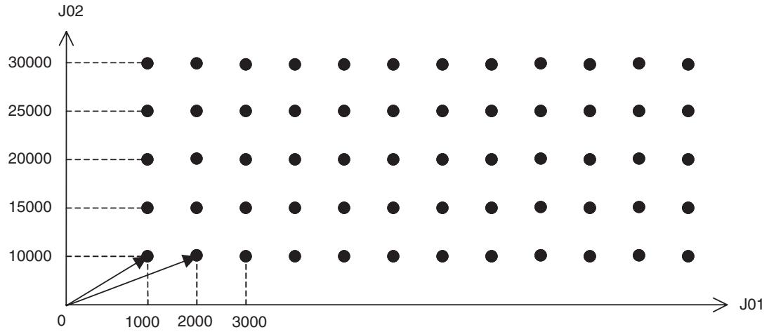
Program
Main program
Explanation of the program
Main program
01) A program No. and axes to be used are specified.
02) Stop Mode is selected.
03) The task variable for counting (DL0000) is reset. (For [J02])
04) The first travel distance of [J02] is entered into the position data (PL0011).
05) With FOR command, the process through 05) to 09) is repeated 5 times.
06) The first travel distance of [J01] is entered into the position data (PL0010).
07) The subprogram (P0501) is called and executed.
08) 5000 is added to the position data (PL0011) of [J02].
09) This is the end of FOR command from 05).
10) The program is completed.
| Subprogram 01) A program No. and axes to be used are specified. 02) The task variable for counting (DL0002) is reset. (For [J01]) 03) With FOR command, the process through 03) to 07) is repeated 10 times. 04) The axes [J01] and [J02] move based on the values in the position data (PL0010) and (PL0011) respectively. 05) The axes return to the origin. 06) 1000 is added to the position data (PL0010) of [J01]. 07) This is the end of FOR command from 03) 08) The subprogram is completed and the main program is resumed. In the program above, the operations of [J01] and [J02] are repeated using the main and subprograms, however, the same operation can be executed with only one program. See the following program. | |
| Program 2 | 01) PROG P008 Q00000003; 02) STOPMODE; 03) #DW0000 = 0; 04) #PL0011 = 10000; 05) WHILE #DW0000 < 5; 06) #DL0002 = 0; 07) #PL0010 = 1000; 08) FOR W#DL0002 L10 S1; 09) MOVEL [J01]#PL0010 [J02]#PL0011 F300000; 10) MOVEL [J01]0 [J02]0; 11) #PL0010 = #PL0010 + 1000; 12) NEXT; 13) #DW0000 = #DW0000 + 1; 14) #PL0011 = #PL0011 + 5000; 15) WEND; 16) END; |
| Explanation of the program 2 | 01) A program No. and axes to be used are specified. 02) Stop Mode is selected. 03) The task variable for counting (DW0000) is reset. (For [J02]) 04) The first travel distance of [J02] is entered into the position data (PL0011). 05) With WHILE command, the process through 05) to 15) is repeated until the conditional expression is satisfied (repeated 5 times). 06) The task variable for counting (DL0002) is reset. (For [J01]) 07) The first travel distance of [J01] is entered into the position data (PL0010). 08) With FOR command, the process through 08) to 12) is repeated 10 times. 09) The axes [J01] and [J02] move based on the values in the position data (PL0010) and (PL0011) respectively. 10) The axes return to the origin. 11) 1000 is added to the position data (PL0010) of [J01]. 12) This is the end of FOR command from 08). 13) 1 is added to the task variable for counting (DW0000) of [J02]. 14) 5000 is added to the position data (PL0011) of [J02]. 15) This is the end of WHILE command from 05). 16) The program is completed. |
10-1-8 Stopping a Program with General Input
Explanation of the operation
- The program advance is held while the general input is ON.
- The axis keeps going back and forth between positions 0 and 20000 until IW0B00 becomes 1.
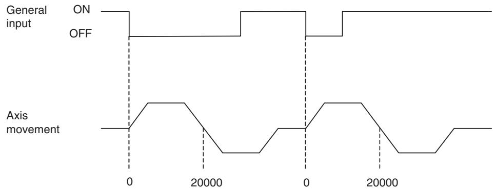
Program
Explanation of the program
01) A program No. and axes to be used are specified.
02) Stop Mode is selected.
03) The general input (IW0B00) is set to 0.
04) With WHILE command, the process through 04) to 08) is repeated when the general input (IW0B00) is not 1.
05) The program waits until the general input (IW0B01) becomes 1.
06) Positioning with linear interpolation is performed to the position [J01]20000.
07) The axis returns to the origin.
08) This is the end of WHILE command from 04).
09) The program is completed.
10-1-9 Stopping Operation with Optional End Using General Input and Assigning Position Data
Explanation of the operation
- Positioning of [J01] to the position 50000 is performed. (A position exceeding the target position)
- Once the axis reaches the target position, the operation will be stopped with optional end after deceleration.
- After the stopping position is assigned to the position data, the axis returns to the origin. After that, positioning is performed based on the assigned position data.
- This program is useful for applications such as the following: There is no original target position for positioning. A target position is decided using the external input. After a target position is decided, positioning to the target position is performed.
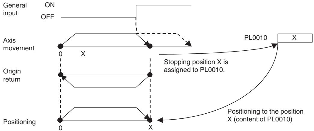
Program
Explanation of the program
01) A program No. and axes to be used are specified.
02) Stop Mode is selected.
03) The first travel distance (50000) is entered into the position data. (A position exceeding the target position)
04) The general input (IW0B00) is set to 0.
05) With STOPOP command, when the general input (IW0B01) becomes 1, the next block will be interrupted midway and ended.
06) Positioning of [J01] with linear interpolation to the position specified by the position data (PL0010) is performed.
07) The program waits for completion of the axis movement.
08) The stopping position is assigned to the position data (PL0010).
09) With WHILE command, the process through 09) to 12) is repeated when the general input (IW0B00) is not 1.
10) Positioning is performed based on the value in the position data (PL0010).
11) The axis returns to the origin.
12) This is the end of WHILE command from 09).
13) The program is completed.
10-1-10 Positioning of Turntable
Explanation of the operation
- Positioning of a turntable is performed using the unlimited length axis function and various arithmetic operations.
-
In positioning to the target position, the travel direction is determined for shorter distance.
-
The target position is to be specified within the range of 0 to 360 degrees. Passing the position of 360 (0) degrees clears the present position to 0.
1,2,3...
- Enter a target position into the position data using IOWR instruction.
- Execute positioning by turning ON the general input for positioning.
- 1 is output to the general output once positioning is completed.
- 0 is output to the general output when the general input for positioning is turned OFF.
- The process through 1 to 4 is repeated until the general input for repeat is turned ON.
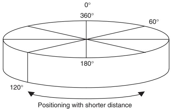
Program
Main program
Explanation of the program
Main program
01) A program No. and axes to be used are specified.
02) With WHILE command, the process through 02) to 23) is repeated until the general input (IW0B00) becomes 1.
03) With WAIT command, the program advance will be held until the general input (IW0B01) becomes 1.
04) The present position is written to the position data (PL0020).
05) The travel distance is calculated with the target position (PL0000) and the present position (PL0020), and the result will be entered into the position data (PL0022).
06) The subprogram (P502) is called and executed.
07) to 17) The rotation direction and the travel distance are calculated and entered into the position data (PL0002).
18) Positioning is performed based on the calculated position data.
19) The program advance will be held until positioning is completed.
20) 1 is output to the general output (OW0BA0).
21) The program advance will be held until the general input (IW0B01) becomes 0.
22) 0 is output to the general output (OW0BA0).
23) This is the end of WHILE command from 02).
24) The program is completed.
Subprogram
01) A program No. and axes to be used are specified.
02) to 04) When data exceeding 360 degrees is entered into the position data by mistake, the target position is corrected to the value within the range 0 to 360 degrees and the main program is resumed. (When an appropriate target position is entered in the position data, the subprogram does not do anything and the main program is resumed.)
05) The program is completed and the main program is resumed.
10-1-11 Feeder Feeding
Explanation of the operation
- Sets the workpiece coordinate system to 0 when started from the CPU Unit.
- The workpiece length is set to 1000.
Note Set the following axis parameters before using feeder feeding. These settings enable axes to continue infinite feeding in a set direction.
- Set the axis feed mode to an infinite axis (P5AA07 = 00000010 Hex)
- Set the reference unit per machine rotation in P5AA04 to a value that is N times the actual length of the workpiece. Use a value less than N times the actual length of the workpiece as the reference position. In the sample program, P5AA04 is set to 100,000, which is 100 × the workpiece length (1,000).
- Set P5AA05 to N times the actual value to when setting a motor gear ratio. In the sample program, P5AA05 is set to 100 times the actual gear ratio.
| Program | 01) PROG P011 Q00000001; |
| 02) WORK C1; | |
| 03) OFFPOS C1 [J01]#SL0206; | |
| 04) INC MOVE [J01]1000; | |
| 05) NOPS; | |
| 06) END; | |
| Explanation of the program | 01) The program number and axes to be used are specified. |
| 02) The workpiece coordinate system (C1) is enabled. | |
| 03) The workpiece coordinate system (C1) offset is changed to the machine coordinate system present position (SL0206) (i.e., the workpiece coordinate system is preset). | |
| 04) Positioning with PTP control is performed from the present position to the position [J01] 1000. | |
| 05) Stepping is stopped until the positioning in step 04 is completed. | |
| 06) The program is completed. |
10-1-12 Starting Peripherals during Axis Movement
Explanation of the program
- During axis movement, peripherals can be started at specified positions without stopping the axes.
- This program enables the control of peripherals without stopping the axes; therefore, high-speed synchronous application can be realized.
- This example shows the operation to start peripherals 1, 2, and 3 accordingly when the present position of [J01] reaches 2500, 5000, and 7500 during linear interpolation with 2 axes.
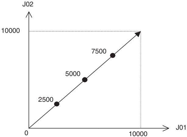
Program
01) PROG P013 Q00000003;
02) MOVEL [J01]0 [J02]0 F300000;
03) #OW0BA0 = 0;
04) #OW0BA1 = 0;
05) #OW0BA2 = 0;
06)WAIT #IW0B00 = = 1;
07) MOVEL [J01]10000 [J02]10000;
08) WAIT #SL0206 > = 2500
09) #OW0BA0 = 1;
10) WAIT #SL0206 > = 5000
11) #OW0BA1 = 1;
12) WAIT #SL0206 > = 7500
13) #OW0BA2 = 1;
14) END;
| Explanation of the program | 01) A program No. and axes to be used are specified. 02) The axes return to the origin. 03) to 05) The general outputs (OW0BA0 to OW0BA2) are reset to 0. 06) The program will wait until the general input (IW0B00) becomes 1. 07) Positioning with linear interpolation is performed to the position [J01]10000, [J02]10000. 08) to 09) When [J01] reaches 2500, 1 will be output to the general output (OW0BA0). 10) to 11) When [J01] reaches 5000, 1 will be output to the general output (OW0BA1). 12) to 13) When [J01] reaches 7500, 1 will be output to the general output (OW0BA2). 14) The program is completed. |
| 10-1-13 High-speed Positioning | |
| Explanation of the operation | ·The CPU Unit reads the present position of a work from a visual sensor and writes the compensated value into the MC Unit after calculation. After receiving the value, the MC Unit performs positioning to the position corresponding to the value. ·The CPU Unit transmits 2 of position data to the MC Unit using IOWR instruction and starts the MC Unit immediately. ·In this case, the data transfer to the MC Unit and the command for positioning can be executed within 1 scan. |
| Program | 01) PROG P014 Q00000003; 02) WHILE #IW0B00 <> 1; 03) MOVEL [J01]0 [J02]0 F300000; 04) NOPS; 05) #OW0BA0 = 1; 06) WAIT #IW0B01 = = 1; 07) #OW0BA0 = 0; 08) MOVEL [J01]#PL0000 [J02]#PL0001; 09) NOPS; 10) #OW0BA1 = 1; 11) WAIT #IW0B02 = = 1; 12) #OW0BA1 = 0; 13) WEND; 14) END; |
| Explanation of the program | 01) A program No. and axes to be used are specified. 02) With WHILE command, the process through 02) to 13) is repeated when the general input (IW0B00) is not 1. 03) The axes return to the origin. 04) to 05) After completion of positioning in 03), 1 is output to the general output (OW0BA0). 06) The program advance will be held until the general input (IW0B01) becomes 1. 07) The general output (OW0BA0) is cleared to 0. 08) The axes move to the position read from the CPU Unit using IOWR instruction. 09) to 10) After completion of positioning in 08), 1 is output to the general output (OW0BA1). |
11) The program advance will be held until the general input (IW0B02) becomes 1.
12) The general output (OW0BA1) is cleared to 0.
13) This is the end of WHILE command from 02).
14) The program is completed.
10-1-14 Interrupt Feeding (MOVEI)
Explanation of the operation
Positioning of [J01] to 100000 is performed. (A position exceeding the target position)
Turning ON an external input stops the axis with interrupt feeding.
When positioning of [J01] is completed, other axes start operating. When other axes complete their operations, [J01] returns to the origin and 1 is output to the general output.
When no external input is turned ON, [J01] returns to the origin without operation of other axes.
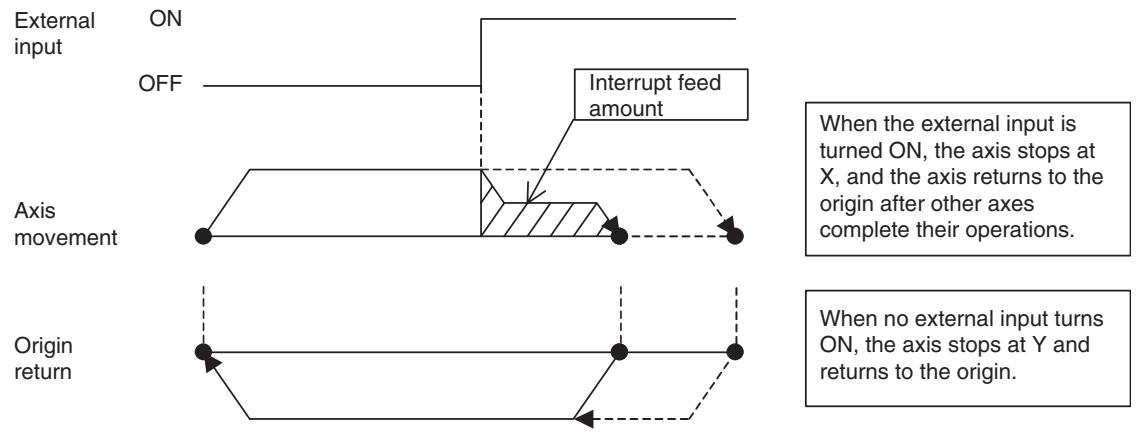
Program
Explanation of the program
01) A program No. and axes to be used are specified.
02) Stop Mode is selected.
03) The first travel distance (50000) is entered into the position data. (A position exceeding the target position)
04) The program will wait until the system variable (SW022A) becomes 1. (Latch being requested)
05) The program will wait for completion of positioning.
06) When the system variable (SW022A) is 2, the command of 07 is executed. When it is not 2, the program jumps to 10). (Latch completed) (With interrupt feeding, the axis returns to the origin after operations of other axes. Without interrupt feeding, the axis returns to the origin immediately.)
07) to 08) Other axes are operated.
09) This is the end of IF command from 06).
10) The axis returns to the origin.
11) to 12) After completion of positioning, 1 is output to the general output (OW0BA0).
13) The program advance will be held until the general input (IW0B00) becomes 1.
14) The general output (OW0BA0) is cleared to 0.
15) The program is completed.
10-1-15 Time-specified Positioning (MOVET)
Explanation of the operation
- This program is used to perform positioning within a specified time period.
- This example shows the following operation; the axes move to the position [J01]10000, [J02]20000 in 3 seconds and 1 is output to the general output. When the general input becomes 1, the general output is cleared to 0. Finally, the axes return to the origin in 6 seconds.
Attention
- When the speed of the axis exceeds the maximum rapid feed rate (P2AA01), the alarm [200Bh: Time specification error] will occur.
- If override other than 100% is used, the specified time period cannot be kept.
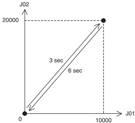
Program
01) PROG P019 Q00000003;
02) MOVE [J01]0 [J02]0;
03) MOVET [J01]10000 [J02]20000 T3000;
04) NOPS;
05) #OW0BA0 = 1;
06) WAIT #IW0B00 = = 1;
07) #OW0BA0 = 0;
08) MOVET [J01]0 [J02]0 T6000;
09) END;
Explanation of the program
01) A program No. and axes to be used are specified.
02) The axes return to the origin.
03) Positioning is performed to the position [J01]10000, [J02]20000 in 3 seconds.
04) to 05) After completion of positioning, 1 is output to the general output (OW0BA0).
06) The program advance will be held until the general input (IW0B00) becomes 1.
07) The general output (OW0BA0) is cleared to 0.
08) With MOVET command, the axes return to the origin in 6 seconds.
09) The program is completed.
10-1-16 Regular Winding to Rough Winding (MOVETRAV)
Explanation of the operation
This example shows a winder that makes 10 layers of 20 winds, and 10 winds on the 11^th layer.
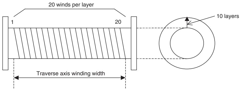
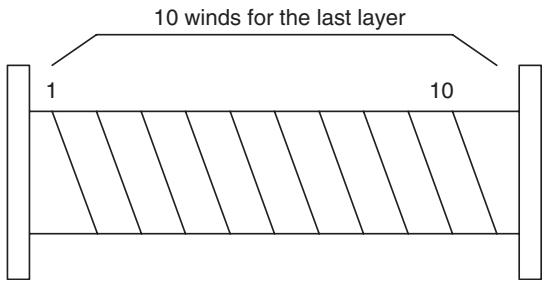
Program
01) PROG P015 Q00000003;
02) MOVETRAV Q1 [J01]7200 [J02]360 L10 F300000;
03) MOVETRAV Q1 [J01]3600 [J02]360 L1;
04) END;
Explanation of the program
01) A program No. and axes to be used are specified.
02) To make 20 winds per layer, the winding axis rotations are set to 7200 deg (360 deg × 20 winds). Also, to make 10 layers, the number of layers (L) is set to 10.
03) To make 10 winds per layer, the winding axis rotations are set to 3600 deg (360 × 10 winds).
04) The program is completed.
- In the program above, the rotations in normal traverse are specified. Changing the mode enables linked traverse or pitch specification.
Mode 1: Normal traverse, Winding axis rotations = Rotations specification
Mode 2: Normal traverse, Winding axis rotations = Pitch specification
Mode 3: Linked traverse, Winding axis rotations = Rotations specification
Mode 4: Linked traverse, Winding axis rotations = Pitch specification
- The example of setting the program above with pitch specification is shown in the next page.
Ex:
Calculation method of the operand
Pitch = Traverse axis winding width/No. of winds per layer
Therefore,
Pitch = 360 / 20 = 18 [command unit/rev]
The program should be changed as shown below:
01) PROG P016 Q00000003;
02) MOVETRAV Q2 [J01]18. [J02]360 L10 F300000;
03) MOVETRAV Q2 [J01]36. [J02]360 L1;
04) END;
Note
(1) For winding axis, unlimited feed mode (P5AA07: 0010h) has to be set.
(2) In linked traverse, up to 100 blocks can be linked, and the operation is executed in Stop Mode.
(3) The linked blocks are treated as 1 block.
(4) In linked traverse, up to 5 blocks are interpreted per Unit Scan. If more than 5 blocks are to be linked, it takes a period of time [(No. of linked blocks/5) x Unit Scan] from execution completion of the last block to operation start. (It will take longer to start execution. The operation does not stop during the linked traverse.)
(5) Linked traverse is always executed at the speed specified for the 1^st traverse.
(6) When the winding axis rotations are set to 0, the alarm [2009h: Position specification error] will occur.
(7) When the traverse axis winding width is set to 0, the alarm [2009h: Position specification error] will occur.
10-1-17 Electronic Cam, Single Axis (CAM)
Explanation of the operation
- Positioning is performed within the specified time period based on the cam data created in advance.
- This example uses the cam data already appeared in SECTION 6 (page 297) to create the cam table and to operate the axes.
1,2,3...
- Positioning is performed with linear interpolation to the position [J01]5000, [J02]5000, and the program will wait until the general input becomes 1.
- Once the general input becomes 1, [J01] will perform the cam operation in 10 seconds based on the cam data shown below.
- When the cam operation is completed, 1 will be output to the general output. When the general input is cleared to 0, the axes [J01] and [J02] will return to the origin.
Cam data
| Data No. | Phase | Displacement |
| 1 | 0 | 0 |
| 2 | 500 | 400 |
| 3 | 1000 | 1600 |
| 4 | 1500 | 3600 |
| 5 | 2000 | 6400 |
| 6 | 2500 | 10000 |
| 7 | 3000 | 13600 |
| 8 | 3500 | 16400 |
| 9 | 4000 | 18400 |
| 10 | 4500 | 19600 |
| 11 | 5000 | 20000 |
| 12 | 5500 | 19600 |
| 13 | 6000 | 18400 |
| 14 | 6500 | 16400 |
| 15 | 7000 | 13600 |
| 16 | 7500 | 10000 |
| 17 | 8000 | 6400 |
| 18 | 8500 | 3600 |
| 19 | 9000 | 1600 |
| 20 | 9500 | 400 |
| 21 | 10000 | 0 |
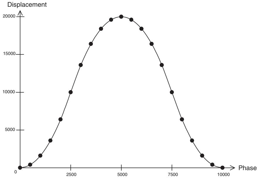
Program
01) PROG P020 Q00000003;
02) STOPMODE;
03) MOVEL [J01]5000 [J02]5000 F500000;
04) WAIT #IW0B00 = = 1;
05) CAM [J01]1 K100. T10000;
06) NOPS;
07) #OW0BA0 = 1;
08) WAIT #IW0B00 = = 0;
09) #OW0BA0 = 0;
10) MOVEL [J01]0 [J02]0;
11) END;
Explanation of the program
01) A program No. and axes to be used are specified.
02) Stop Mode is selected.
03) Positioning is performed with linear interpolation to the position [J01]5000, [J02]5000.
04) The program will wait until the general input (IW0B00) becomes 1.
05) [J01] performs the cam operation in 10 seconds based on the cam table 1.
06) to 07) After positioning is completed, 1 will be output to the general output (OW0BA0).
08) The program advance will be held until the general input (IW0B00) becomes 0.
09) The general output (OW0BA0) is cleared to 0.
10) The axes return to the origin.
11) The program is completed.
10-1-18 Link Operation (MOVELINK)
Explanation of the operation
- Positioning is performed with a slave axis synchronizing to a specified master axis.
- In this example, the master axis will start operating when the general input becomes 1. The slave axis will start synchronization when the master axis reaches the position 5000. In this synchronization, the slave axis travels for 30000 while the master axis travels for 60000. 1 will be output to the general output once the master axis reaches the position 90000. The link operation is repeated with WHILE command.
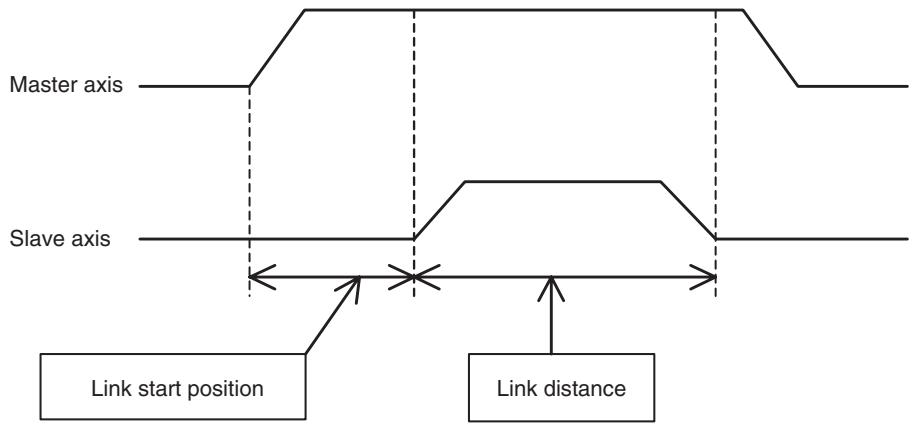
Program
01) PROG P017 Q00000003;
02) #PL0010 = 0;
03) WHILE #IW0B00 <> 1;
04) OFFPOS C1 [J01]#PL0010;
05) WORK C1;
06)WAIT #IW0B01 = = 1;
07) MOVELINK [J02]30000 [J01]60000 A1000 D1000 Q5 I5000;
08) INC MOVEL [J01]90000 F300000;
09) NOPS;
10) #OW0BA0 = 1;
11) WAIT #IW0B01 = = 0;
12) #OW0BA0 = 0;
13) #PL0010 = #SL0206;
14) WEND;
15) END;
Explanation of the program
01) A program No. and axes to be used are specified.
02) The position data used as a workpiece coordinate is cleared to 0.
03) When the general input (IW0B00) is not 1, the process through 03) to 14) is repeated.
04) to 05) The workpiece coordinate system (C1) is enabled.
06) The program will wait until the general input (IW0B01) becomes 1.
07) The link operation, in which the slave axis travels for 30000 while the master travels for 60000, is performed. The link start position is 5000. (The slave starts synchronization once the master reaches the position 5000.)
08) The master axis moves from the present position to the position 90000 with linear interpolation.
09) to 10) After positioning is completed, 1 will be output to the general output (OW0BA0).
11) The program advance will be held until the general input (IW0B01) becomes 0.
12) The general output (OW0BA0) is cleared to 0.
13) The present position of the master axis is entered into the position data for the workpiece coordinate.
14) This is the end of WHILE command from 03).
15) The program is completed.
10-1-19 Electronic Cam, Synchronous (CAMBOX)
Explanation of the operation
The slave axis operates based on the cam table while synchronizing to a specified axis (master axis).
In this example, the master axis will start operating when the general input becomes 1. The slave axis will start synchronization when the master reaches the position 5000. The slave performs 1 cycle of the cam operation while the master travels for 60000. 1 will be output to the general output once the master reaches the position 90000. The synchronization is repeated with WHILE command.
The same cam data in 10-1-17 Electronic Cam, Single Axis (CAM) (page 592) is used in this example.
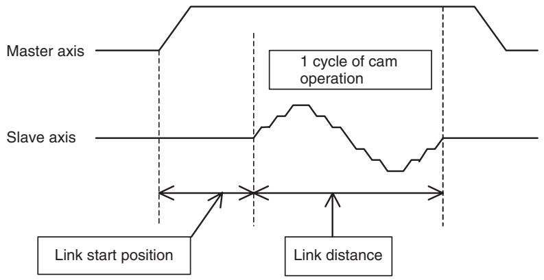
Program
Explanation of the program
01) A program No. and axes to be used are specified.
02) The position data used as a workpiece coordinate is cleared to 0.
03) When the general input (IW0B00) is not 1, the process through 03) to 14) is repeated.
04) to 05) The workpiece coordinate system (C1) is enabled.
06) The program will wait until the general input (IW0B01) becomes 1.
07) The slave axis performs 1 cycle of the cam operation based on the cam table 1 while the master travels for 60000.
(The slave axis will start cam operation once the master reaches the position 5000.)
08) The master axis moves from the present position to the position 90000 with linear interpolation.
09) to 10) After positioning is completed, 1 will be output to the general output (OW0BA0).
11) The program advance will be held until the general input (IW0B01) becomes 0.
12) The general output (OW0BA0) is cleared to 0.
13) The present position of the master axis is entered into the position data for the workpiece coordinate.
14) This is the end of WHILE command from 03).
15) The program is completed.
10-1-20 Electronic Shaft (CONNECT)
Explanation of the operation
- The slave axis operates based on the specified gear ratio while synchronizing to the master axis.
- In this example, the operation of the master axis is divided into 3 intervals. The gear ratio for the slave axis against the master axis is changed to 1/2 , 1, and 2 with CONNECT command. The operation is held for 3 seconds between intervals.

Program
01) PROG P022 Q00000003;
02) CONNECT [J02]1 [J01]2;
03) MOVEL [J01]50000 F500000;
04) DWELL T3000;
05) CONNECT [J02]1 [J01]1;
06) MOVEL [J01]100000;
07) DWELL T3000;
08) CONNECT [J02]2 [J01]1;
09) MOVEL [J01]150000;
10) DWELL T3000;
11)SYNCR [J02];
12) MOVE [J01]0 [J02]0;
13) END;
Explanation of the program
01) A program No. and axes to be used are specified.
02) The gear ratio of 1 to 2 is set.
03) The master axis moves to the position 50000 at 500 rpm. (The slave synchronizes to the master and moves at 250 rpm.)
04) The operation is held for 3 seconds.
05) The gear ratio of 1 to 1 is set.
06) The master axis moves to the position 100000 at 500 rpm. (The slave synchronizes to the master and moves at 500 rpm.)
07) The operation is held for 3 seconds.
08) The gear ratio of 2 to 1 is set.
09) The master axis moves to the position 150000 at 500 rpm. (The slave synchronizes to the master and moves at 1000 rpm.)
10) The operation is held for 3 seconds.
11) The synchronization is canceled.
12) The axes return to the origin.
13) The program is completed.
10-1-21 Trailing Synchronization/Synchronization Cancel (SYNC/SYNCR)
Explanation of the operation
- The slave axis will start trailing the master axis when the marker sensor (external input) turns ON. When it catches up with the master axis, synchronization with the ratio of 1 to 1 will be performed.
- In this example, trailing synchronization is performed with the slave executed by the motion task 1 and the master executed by the motion task 2. (The program starts the slave first, and then the master.)
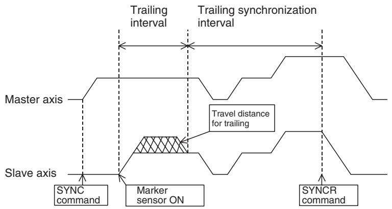
Program 1
(Slave axis)
| Explanation of the program | (Master axis) 01) PROG P024 Q00000001; 02) MOVEL [J01]30000 F500000; 03) DWELL T5000; 04) MOVEL [J01]60000; 05) MOVEL [J01]100000 F1000000; 06) DWELL T3000; 07) #ML0000 = 1; 08) MOVEL [J01]0; 09) #ML0000 = 0; 10) END; |
| (Slave axis) 01) A program No. and axes to be used are specified. 02) The trailing synchronization with the catch-up position offset of 5000 and the marker sensor ON position of 10000 is executed. 03) to 04) The synchronization will be canceled when the present position of the master exceeds 80000. 05) The program will wait until the global general variable (ML0000) becomes 1. 06) The slave axis returns to the origin. 07) The program is completed. | |
| (Master axis) 01) A program No. and axes to be used are specified. 02) The master axis moves to the position 30000 at 500 rpm. 03) The operation is held for 5 seconds. 04) The master axis moves to the position 60000 at 500 rpm. 05) The master axis moves to the position 100000 at 1000 rpm. 06) The operation is held for 3 seconds. 07) The global general variable (ML0000) becomes 1. 08) The master axis returns to the origin. 09) The global general variable (ML0000) becomes 0. 10) The program is completed. |
10-1-22 Travel Distance Superimpose/Travel Distance Superimpose Cancel (ADDAX/ADDAXR)
Explanation of the operation
- The operation of the specified master axis is superimposed on the slave axis.
- In this example, the operation of the master axis is divided into 3 intervals and the operation of the 2^nd interval is superimposed on the slave. (The program starts the master and slave simultaneously.)
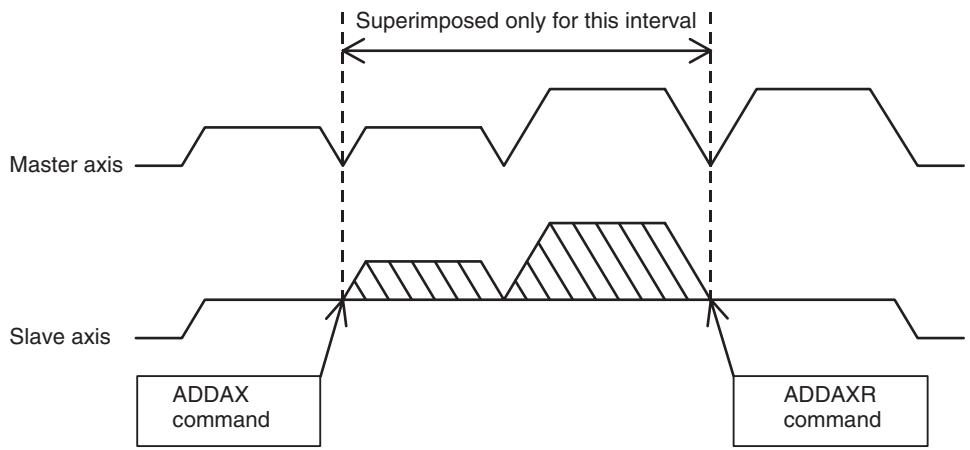
Program
(Master axis)
Explanation of the program
(Master axis)
01) A program No. and axes to be used are specified.
02) Stop Mode is selected.
03) The master axis moves to the position 50000 at 500 rpm.
04) to 05) After positioning is completed, 1 will be output to the global general variable (MW0000).
06) The master axis moves to the position 100000 at 500 rpm.
07) The master axis moves to the position 150000 at 1000 rpm.
08) to 09) After positioning is completed, 0 will be output to the global general variable (MW0000).
10) The master axis moves to the position 200000 at 1000 rpm.
11) The operation is held for 3 seconds.
12) 1 is output to the global general variable (MW0001).
13) The program will wait until the global general variable (MW0002) becomes 1.
14) The master axis returns to the origin.
15) The global general variable (MW0001) is reset to 0.
16) The program is completed.
(Slave axis)
01) A program No. and axes to be used are specified.
02) With PARALLEL command, 03) and the process through 05) to 08) are executed in parallel.
03) The slave axis moves to the position 200000 at 500 rpm.
04) This is the syntax of PARALLEL command from 02).
05) to 06) Superimposition will start when the global general variable (MW0000) becomes 1.
07) to 08) Superimposition will start when the global general variable (MW0000) becomes 0.
09) This is the end of PARALLEL command from 02).
10) The operation is held for 3 seconds.
11) The program will wait until the global general variable (MW0001) becomes 1.
12) 1 is output to the global general variable (MW0002).
13) The slave axis returns to the origin.
14) The global general variable (MW0002) is reset to 0.
15) The program is completed.
10-1-23 Speed Control/Speed Control Cancel (SPEED/SPEEDR)
Explanation of the operation
- The speed of a specified axis is controlled in Speed Control Mode.
- In this example, SPEED command will be executed between positions 50000 and 150000 when the axis travels from position 0 to 200000. During execution of SPEED command, 1 is output to the general output (OW0BA0).
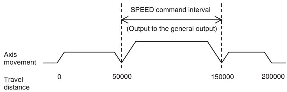
| Program | 01) PROG P027 Q00000001; |
| 02) MOVEL [J01]50000 F500000; | |
| 03) SPEED [J01]50. T0; | |
| 04) #OW0BA0 = 1; | |
| 05) WAIT #SL0204 >= 150000; | |
| 06) SPEEDR [J01] T0; | |
| 07) #OW0BA0 = 0; | |
| 08) MOVEL [J01]200000; | |
| 09) DWELL T5000; | |
| 10) MOVEL [J01]0; | |
| 11) END; | |
| Explanation of the program | 01) A program No. and axes to be used are specified. |
| 02) The axis moves to the position 50000 with linear interpolation. | |
| 03) SPEED command operation is started with 50% of the rated speed of the motor. | |
| 04) 1 is output to the general output (OW0BA0). | |
| 05) The program will wait until the present position exceeds 150000. | |
| 06) SPEED command operation is completed. | |
| 07) The general output (OW0BA0) is reset to 0. | |
| 08) The axis moves to the position 200000 with linear interpolation. | |
| 09) The program is held for 5 seconds. | |
| 10) The axis returns to the origin. | |
| 11) The program is completed. |
10-1-24 Torque Control/Torque Control Cancel (TORQUE/TORQUER)
Explanation of the operation
- The torque of a specified axis is controlled in Torque Control Mode.
- In this example, TORQUE command will be executed between positions 50000 and 150000 when the axis travels from position 0 to 200000. During execution of TORQUE command, 1 is output to the general output (OW0BA0).
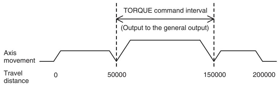
Program
Explanation of the program
01) A program No. and axes to be used are specified.
02) The axis moves to the position 50000 with linear interpolation.
03) TORQUE command operation is started with 50% of the maximum motor torque.
04) 1 is output to the general output (OW0BA0).
05) The program will wait until the present position exceeds 150000.
06) TORQUE command operation is completed.
07) The general output (OW0BA0) is reset to 0.
08) The axis moves to the position 200000 with linear interpolation.
09) The program is held for 5 seconds.
10) The axis returns to the origin.
11) The program is completed.
10-1-25 Target Position Change (MOVEMODI)
Explanation of the operation
- A target position is changed during positioning.
- In this example, the axis is moving to the position 20000 with linear interpolation. The target position (20000) will be changed to the position 40000 if the general input is ON when the axis reaches the position 10000. If the general input is OFF, the target position will remain the same (20000).
Note Target positions can be changed only on the axes operated with MOVE command, or MOVEL command of single axis specification in Stop Mode. (MOVE-MODI during execution of commands other than the ones mentioned above, or for axes not operating is ignored.)
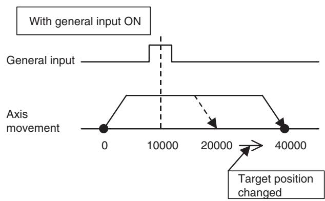
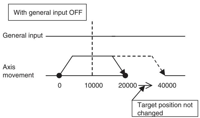
Program
Explanation of the program
01) A program No. and axes to be used are specified.
02) Stop Mode is selected.
03) The axis moves to the position 20000 with linear interpolation.
04) to 07) When the present position reaches 10000, if the general input (IW0B00) is 1, the target position will be changed to 40000. If the general input (IW0B00) is not 1, the target position will not be changed.
08) The program is held for 3 seconds.
09) The axis returns to the origin.
10) The program is completed.
10-1-26 Present Position Latch (LATCH)
Explanation of the operation
- The present position of a specified axis is saved to the word for variables.
- In this example, the axis moves to the position 100000 (a position exceeding the target position). When the external input is turned ON in the midway, the position will be assigned to the position data.
- The axis movement is similar to the one of 10-1-9 Stopping Operation with Optional End Using General Input and Assigning Position Data (page 583), however, the axis does not stop midway in the initial operation, moves to the position 100000, and returns to the origin.
- Positioning after execution of LATCH command is performed using the assigned position data. Additionally, if the latch start and end positions are specified, the rise of the external inputs outside of the range will be ignored. This can be useful when the external input turns ON twice or more due to the machine structure.
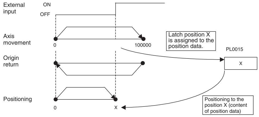
Program
Explanation of the program
01) A program No. and axes to be used are specified.
02) Stop Mode is selected.
03) With PARALLEL command, 04) and 06) are executed in parallel.
| 04) The axis moves to the position 100000 with linear interpolation. 05) This is the syntax of PARALLEL command. 06) If the external input is turned ON between the start position 80000 and the end position 90000, the ON position will be assigned to the position data (PL0015). 07) This is the end of PARALLEL command from 03). 08) The axis returns to the origin. 09) The process through 09) to 12) is repeated when the general input (IW0B00) is not 1. 10) Positioning is performed based on the position data. 11) The axis returns to the origin. 12) This is the end of WHILE command from 09). 13) The program is completed. | |
| 10-1-27 Single Block Ignored (NSTOP) | |
| Explanation of the operation | ·The block with NSTOP command is not stopped with block stop in Single Block Operation Mode. ·For example, when debugging a program in Single Block Operation Mode, if NSTOP command is put in the blocks not containing axis movement commands, the blocks will not be stopped (other blocks with axis movement commands will be stopped). This will economizes the time and work for debugging. |
| Note | When debugging a program in Single Block Operation Mode, Start Mode 2 has to be set in advance. |
| Program | 01) PROG P031 Q00000003; 02) MOVEL [J01]50000 [J02]50000 F500000; 03) NSTOP NOPS; 04) NSTOP #PL0000 = #SL0204; 05) NSTOP #PL0001 = #PL0000 * 3; 06) NSTOP #PL0002 = #PL0001 + #PL0000; 07) NSTOP #PL0003 = #PL0002 / 4; 08) NSTOP #PL0004 = #PL0003 + #PL0000; 09) MOVEL [J01]#PL0004 [J02]#PL0004; 10) NSTOP DWELL T5000; 11) MOVEL [J01]0 [J02]0; 12) END; |
| Explanation of the program | 01) A program No. and axes to be used are specified. 02) The axis moves to the position [J01]50000, [J02]50000 with linear interpolation. 03) to 08) Various arithmetic operations are executed. (Not stopped at the end of the block in Single Block Operation Mode) 09) Positioning is performed based on the result of the arithmetic operations. 10) The program is held for 5 seconds. (Not stopped at the end of the block in Single Block Operation Mode.) 11) The axes return to the origin. 12) The program is completed. When executing the above program to END command in Single Block Operation Mode, the start signal will be turned OFF-ON 5 times. Without NSTOP command, the start signal will be turned OFF-ON 12 times. |
10-1-28 Parallel Execution (PARALLEL, JOINT, JWAIT)
Explanation of the operation
- The processing is branched and executed in parallel.
- This program is used, for example, when executing interpolation commands simultaneously.
- In this example, 3 axes are operated with linear interpolation and they are simultaneously operated with PARALLEL command.
Normal axis movement
Axis movement in Parallel Execution
J01
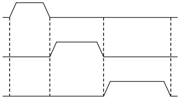
J01
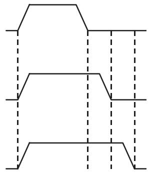
Program
Explanation of the program
01) A program No. and axes to be used are specified.
02) With PARALLEL command, 03), 05), and 07) are executed in parallel.
03) [J01] is moved to the position 100000 with linear interpolation.
04) This is the syntax of PARALLEL command. After this block is
05) [J02] is moved to the position 150000 with linear interpolation.
06) This is the syntax of PARALLEL command. After this block is
07) [J03] is moved to the position 200000 with linear interpolation.
08) This is the end of PARALLEL command from 02).
09) The program is held for 3 seconds.
10) The axes return to the origin.
11) The program is completed.
10-1-29 Selective Execution (SWITCH, CASE, BREAK, SEND)
Explanation of the operation
- The processing is selectively executed according to the values of conditional variables.
- In this example, different operations are executed depending on the values of the general input at program startup.
| Combination | General input 1 (0B01) | General input 2 (0B02) | [J01] | [J02] | [J03] |
| 1 | 2 | 1 | ○ | × | × |
| 2 | 1 | 2 | × | ○ | × |
| 3 | 2 | 2 | ○ | ○ | × |
| 4 | 1 | 1 | × | × | ○ |
Note indicates that the axis is operated.
Program
Explanation of the program
01) A program No. and axes to be used are specified.
02) With WHILE command, the process through 02) to 07) will be repeated until the general input (IW0B00) becomes a value other than 0.
03) The conditional variable (ML0000) is reset to 0.
04) to 06) Depending on the values of the general inputs (IW0B01, IW0B02), the bit of the conditional variable (ML0000) is turned ON.
07) This is the end of WHILE command from 02).
08) to 20) With SWITCH command, when the conditional variable (ML0000) is 1, 2, or 4, processing 1, 2, or 3 will be executed respectively. Processing 4 will be executed when the conditional variable is not 1, 2, or 4.
09) to 11)Content of processing 1
12) to 14)Content of processing 2
15) to 17)Content of processing 3
18) to 19)Content of processing 4
20)This is the end of SWITCH command.
21) The axes return to the origin.
22) The program is completed.
10-2 Slave Modules
This section describes the parameter settings, the allocation area status, and the program examples for operations when the I/O module is specified as the MECHATROLINK-II device.
Note For details of functions, etc., refer to YASKAWA ELECTRIC CORPORATION's Σ-II SERIES SGDH MECHATROLINK-II APLLICATION MODULE USER'S MANUAL MODEL: JUSP-NS115 (MANUAL NO. SIEPC71080001*)".
10-2-1 Using 64-Point I/O Module
The parameter settings and the allocation example when I/O modules are connected to the MECHATROLINK device are shown below.
Explanation of the operation
Allocate 64-point I/O module at node 2 to Axis 3 of the MC Unit.
Parameter settings
Set Axis 3 to I/O in the system parameter of the MC Unit.
| No. | Setting value | Name | Detail |
| P1AA01 | 2 | Physical axis setting | Set node address to “2”. |
| P1AA02 | 100 | MLK-II device classification | I/O |
| P1AA03 | 4 | Input allocation points | Input - 4 words |
| P1AA04 | 4 | Output allocation points | Output - 4 words |
| P1AA05 | 0 | Axis allocation first address | The first address of destination word for storing the count values (Not specified) (See note 3.) |
| P1AA06 | 0 | MLK-II communications error detection | (Default value) |
Note (1) AA = 03 (Axis 3)
(2) With P1AA02 set to I/O (100), 6 parameters above are valid. (Others are ignored.)
(3) The contents of the address specified here are reflected in the system variable [Current coordinate system FB position]. (For Axis 3: IL0032h_SL0260h) Only 1 word can be monitored.
I/O variables specifications
The following is the relations between the I/O module with the above parameter settings and I/O variables in the MC Unit. (The addresses are the ones for the I/O module allocated as Axis 3.)
Input variables
| Address | Bit | Symbol | Name | Description |
| IW0030 | 0 to 15 | - | Input (IN1)1 to 16 | Shows status of input signal (connector 1).Input 1 to Input 16 |
| IW0031 | 0 to 15 | - | Input (IN1)17 to 32 | Shows status of input signal (connector 1).Input 17 to Input 32 |
| IW0032 | 0 to 15 | - | Input (IN2)1 to 16 | Shows status of input signal (connector 2).Input 1 to Input 16 |
| IW0033 | 0 to 15 | - | Input (IN2)17 to 32 | Shows status of input signal (connector 2).Input 17 to Input 32 |
Output variables
| Address | Bit | Symbol | Name | Description |
| OW0030 | 0 to 15 | - | Output (OUT1) 1 to 16 | Controls status of output signal (connector 1) Output 1 to output 16 |
| OW0031 | 0 to 15 | - | Output (OUT1) 17 to 32 | Controls status of output signal (connector 1) Output 17 to output 32 |
| OW0032 | 0 to 15 | - | Output (OUT2) 1 to 16 | Controls status of output signal (connector 2) Output 1 to output 16 |
| OW0033 | 0 to 15 | - | Output (OUT2) 17 to 32 | Controls status of output signal (connector 2) Output 17 to output 32 |
- Appropriate parameter settings enable data link between I/O variable addresses of each axis and the I/O module.
- For details of the I/O variable area, see 4-6 I/O Variables (page 160).
10-2-2 Using Counter Module
This section describes the parameter settings, the initial module settings, and the allocation examples when the counter module is connected to the MECHATROLINK device.
Explanation of the operation
Allocate the counter module at node 4 to Axis 5 of the MC Unit.
Set Axis 5 to I/O in the system parameter of the MC Unit.
Parameter settings
| No. | Setting value | Name | Detail |
| P1AA01 | 5 | Physical axis setting | Set the address to “5”. |
| P1AA02 | 100 | MLK-II device classification | I/O |
| P1AA03 | 5 | Input allocation points | Input - 5 words |
| P1AA04 | 6 | Output allocation points | Output - 6 words |
| P1AA05 | 10051Hex | Axis allocation first address | The first address of destination word for storing the count valuesIW0051 (See note 3.) |
| P1AA06 | 0 | MLK-II communications error detection | (Default value) |
Note (1) AA = 05 (Axis 5)
(2) With P1AA02 set to I/O (100), 6 parameters above are valid. (Others are ignored.)
(3) The contents of the address specified here are reflected in the system parameter [Current coordinate system FB position]. (For Axis 5: IL0051h_SL02C0h) Only 1 word can be monitored.
Program for initial setting
When using the counter module with the MC Unit, the initial setting for the counter module has to be performed through the motion program.
PROG P000 Q00000000; ^*MCIR Counter module initial setting
OW0050 = 0;
WAIT #IW0050 = = 1;
OW0052 = 0;----Pulse count setting (Phase A, B, × 1 )
OB00500 = 1;---Counter 1 mode setting
WAIT #IB00501 = = 1; ---- Mode setting completed normally
OB00500 = 0; ---Mode setting reset
WAIT #IB00501 = = 0; ---- Mode setting completed normally (Flag OFF monitored)
^*** Present position preset
OL0052 = 2147483647;---present position setting value
OB00502 = 1;---Present value setting ON
WAIT #IB00501 == 1; -- → Present position setting completed
OL0052 = 0;-----Present position setting value (cleared)
OB00502 = 0;-----Present value setting OFF
WAIT #IB00501 = = 0; --- → (Flag OFF monitored)
OB00503 = 1; Counting enabled
END;
Note
(1) Make sure to create a program to confirm a response for a command.
(2) After setting is completed, turn ON "Counter 1 count enable (OW0050-3bit)". With the output variable OFF, the present value of the counter on the MC Unit cannot be monitored.
(3) When executing a synchronous command having the input of the counter module as the master axis, the link option "When master axis is detected" cannot be used to start synchronization (ignored). The link option "When master axis reaches link start position" can be used.
(4) Executing present position preset on the module during execution of synchronous command makes the MC Unit to recognize (though not true) that the axis was moved from the position before the preset to the one after the preset, which causes the slave axis to operate.
I/O variables specification
The following is the relations between the counter module with the above parameter settings and I/O variables in the MC Unit. (The addresses are the ones for the counter module allocated as Axis 5.)
Input variables
| Address | Bit | Symbol | Name | Description |
| IW0050 | 0 | RDY | Ready | Indicates the result of self-diagnosis for the module. ON: Normal OFF: Abnormal |
| 1 | ACK | Setting normal | Indicates the setting operation was completed normally. Stays ON while the setting signal is ON. | |
| 2 | ERR | Setting error | Indicates the setting operation caused an error. Stays ON while the setting signal is ON. | |
| 3 to 7 | Not used | |||
| 8 | CARY1 | Counter 1, Carry | Turns ON for 1 scan when counter's current value with incremental pulses exceeded counter's upper limit value. | |
| 9 | BORW1 | Counter 1, Borrow | Turns ON for 1 scan when counter's current value with decremental pulses exceeded counter's lower limit value. | |
| 10 | N1 | Counter 1, Notch output status | Indicates the status of external Notch output. ON: External Notch being output | |
| 11 | L1 | Counter 1, Latch input status | Indicates the status of external Latch input. ON: External Latch being input | |
| 12 | CARY2 | Counter 2, Carry | Turns ON for 1 scan when counter's current value with incremental pulses exceeded counter's upper limit value. | |
| 13 | BORW2 | Counter 2, Borrow | Turns ON for 1 scan when counter's current value with decremental pulses exceeded counter's lower limit value. | |
| 14 | N2 | Counter 2, Notch output status | Indicates the status of external Notch output. ON: External Notch being output | |
| 15 | L2 | Counter 2, Latch input status | Indicates the status of external Latch input. ON: External Latch being input | |
| IW0051 | 0 to 15 | Monitor | Content of monitor is to be as follows through the initial setting: • Current value • Latch data • Mode settings • Notch point setting value 1 (counter 1) • Notch point setting value 1 (counter 2) • Current set value | |
| IW0052 | ||||
| IW0053 | ||||
| IW0054 |
Note Content of monitor
| Monitor type | IW0051 | IW0052 | IW0053 | IW0054 |
| Current value | Counter 1, Current value (Lower byte) | Counter 1, Current value (Upper byte) | Counter 2, Current value (Lower byte) | Counter 2, Current value (Upper byte) |
| Latch data | Counter 1, Latch data (Lower byte) | Counter 1, Latch data (Upper byte) | Counter 2, Latch data (Lower byte) | Counter 2, Latch data (Upper byte) |
| Mode setting | Counter 1, Mode | Counter 2, Mode | ||
| Notch point setting value 1 (Counter 1) | Counter 1, Notch point (Lower limit) (Lower byte) | Counter 1, Notch point (Lower limit) (Upper byte) | Counter 1, Notch point (Upper limit) (Lower byte) | Counter 1, Notch point (Upper limit) (Upper byte) |
| Notch point setting value 2 (Counter 2) | Counter 2, Notch point (Lower limit) (Lower byte) | Counter 2, Notch point (Lower limit) (Upper byte) | Counter 2, Notch point (Upper limit) (Lower byte) | Counter 2, Notch point (Upper limit) (Upper byte) |
| Current set value | Counter 1, Current set value (Lower byte) | Counter 1, Current set value (Upper byte) | Counter 2, Current set value (Lower byte) | Counter 2, Current set value (Upper byte) |

Monitor (IW0051 to IW0054) and Setting values (OW0052 to OW0055) use the same address (register) depending on the mode. Therefore, make sure that the timings of setting and monitor do not overlap.
In addition, make sure to reset the set values to "0" after the setting is completed. In some mode, data of the setting values (OW0052 to OW0055) is enabled immediately when the mode is set. Therefore, expected operations may not be performed unless the previous settings are reset to "0".
Output variables
| Address | Bit | Symbol | Name | Description |
| OW0050 | 0 | M-SET1 | Counter 1 Mode set | The counter mode setting signal ON: Mode setting signal is effective |
| 1 | N-SET1 | Counter 1 Notch point setting | The notch point setting preset signal Notch point is set at the rise of the signal (OFF-ON). | |
| 2 | P-SET1 | Counter 1 Current value setting | The counter's current value preset signal Current value is set at the rise of the signal (OFF-ON). | |
| 3 | C-ENB1 | Counter 1 Count enable | Input pulses can be counted when this is ON. ON: Count enabled | |
| 4 | N-ENB1 | Counter 1 Notch output enable | Notch output can be output when this is ON. ON: Notch output enabled | |
| 5 | P-RES1 | Counter 1 Current value reset | Counter's current value is reset to “0”. Current value is reset at the rise of the signal (OFF-ON). | |
| 6 | N-RES1 | Counter 1 Notch output reset | Latch status for notch output is reset. Latch status is reset at the rise of the signal (OFF-ON). | |
| 7 | L-RES1 | Counter 1 Count value reset | Input status of external latch is reset. Input status is reset at the rise of the signal (OFF-ON). | |
| 8 | M-SET2 | Counter 2 Mode set | The counter mode setting signal ON: Mode setting signal is effective | |
| 9 | N-SET2 | Counter 2 Notch point setting | The notch point setting preset signal Notch point is set at the rise of the signal (OFF-ON). | |
| 10 | P-SET2 | Counter 2 Current value setting | The counter's current value preset signal Current value is set at the rise of the signal (OFF-ON). | |
| 11 | C-ENB2 | Counter 2 Count enable | Input pulses can be counted when this is ON. ON: Count enabled | |
| 12 | N-ENB2 | Counter 2 Notch output enable | Notch output can be output when this is ON. ON: Notch output enabled | |
| 13 | P-RES2 | Counter 2 Current value reset | Counter's current value is reset to “0”. Current value is reset at the rise of the signal (OFF-ON). | |
| 14 | N-RES2 | Counter 2 Notch output reset | Latch status for notch output is reset. Latch status is reset at the rise of the signal (OFF-ON). | |
| 15 | L-RES2 | Counter 2 Count value reset | Input status of external latch is reset. Input status is reset at the rise of the signal (OFF-ON). | |
| OW0051 | 0 | N-ON1 | Counter 1 Forced notch output | Notch output is forced ON. ON: Forced output |
| 1 | N-ON2 | Counter 2 Forced notch output | Notch output is forced ON. ON: Forced output | |
| 2 to 7 | Not used | |||
| 8 | MON1 | Monitor 1 | Combining the ON/OFF status of Monitor 1 to 3 enables monitoring of the followings. | |
| 9 | MON2 | Monitor 2 | • Counter current value | |
| 10 | MON3 | Monitor 3 | • External latch data | |
| 11 to 15 | Not used | • Status | ||
| • Mode settings | ||||
| • Counter 1, Notch point setting value | ||||
| • Counter 2, Notch point setting value | ||||
| • Current set value | ||||
| OW0052 | 0 to 15 | Setting values | The following 3 counter data settings are available: • Mode settings • Notch point setting • Current value setting | |
| OW0053 | ||||
| OW0054 | ||||
| OW0055 |
Program example
With the above settings, the program that makes the slave axis [J04] link to the input of the counter module [J05] as the master axis is shown below (The same specification method as the normal axes can be used):
PROG P001 Q00000001; Link option (Start position)
WAIT #OB00503 = = 1; Counter, monitor started
WHILE #IB03411 = = 1; Task 2 start switch
MOVELINK [J01]100 [J05]100 A0 D0 Q4 I100 B1;----- Link operation (Start
position)
NOPS;
WEND;
END;
Note Start positions or travel distances for the counter module are processed only with pulses.
10-2-3 Using Pulse Output Module
The following shows the parameter settings and the allocation example when the pulse output module is connected to the MECHATROLINK device.
Explanation of the operation
Allocate the pulse output module at node 2 to Axis 3 of the MC Unit.
Parameter settings
Set the Axis 3 to I/O in the system parameter of the MC Unit.
| No. | Setting value | Name | Detail |
| P1AA01 | 2 | Physical axis setting | Set the address to “2”. |
| P1AA02 | 100 | MLK-II device classification | I/O |
| P1AA03 | 6 | Input allocation points | Input - 6 words |
| P1AA04 | 6 | Output allocation points | Output - 6 words |
| P1AA05 | 10032Hex | Axis allocation first address | The first address of destination word for storing the count valuesIW0032 (See note 3.) |
| P1AA06 | 0 | MLK-II communications error detection | (Default value) |
Note (1) AA = 03 (Axis 3)
(2) With P1AA02 set to I/O (100), 6 parameters above are valid. (Others are ignored.)
(3) The contents of the address specified here are reflected in the system parameter [Current coordinate system FB position]. (With Axis 3: IL0032h_SL0260h) Only 1 word can be monitored.
I/O variables specifications
The following is the relations between the pulse output module with the above parameter settings and I/O variables in the MC Unit. (The addresses are the ones for the pulse output module allocated as Axis 3.)
Input variables
| Address | Bit | Symbol | Name | Description |
| IW0030Word 1 | 0 | RDY1 | Ready(Word 1) | Indicates the result of self-diagnosis for the module. ON: Normal OFF: Abnormal |
| 1 | Not used | |||
| 2 | MONSEL1 | Monitor parameters | Indicates that the parameters are being monitored. | |
| 3 | Not used | |||
| 4 | PACK1 | Parameter settings normal | Indicates that the setting operation was completed nor-mally. Stays ON while the setting signal is ON. | |
| 5 | PNACK1 | Parameter setting error | Indicates that the setting operation caused an error. Stays ON while the setting signal is ON. | |
| 6,7 | Not used | |||
| 8 | MOV1L | Positioning | Indicates that the positioning operation is being performed. | |
| 9 | JOG1L | JOG operation | Indicates that the JOG operation is being performed. | |
| 10 | ZRN1L | Zero point return | Indicates that the zero point return operation is being per-formed. | |
| 11 | Not used | |||
| 12 | OVER1 | Overheat input status | Indicates the status of the external overheat input. (External input terminal) | |
| 13 | TIMING1 | Magnetic excitation timing input status | Indicates the status of the external magnetic excitation tim-ing input. (External input terminal) | |
| 14 | ZRN1 | Zero point signal input status | Indicates the status of the external zero point signal input. (External input terminal) | |
| 15 | IN1 | General-purpose input status | Indicates the status of the external general-purpose input. (External input terminal) | |
| IW0031Word 2 | 0 | RDY2 | Ready(Word 2) | Indicates the result of self-diagnosis for the module. ON: Normal OFF: Abnormal |
| 1 | Not used | |||
| 2 | MONSEL2 | Monitor parameters | Indicates that the parameters are being monitored. | |
| 3 | Not used | |||
| 4 | PACK2 | Parameter settings normal | Indicates that the setting operation was completed nor-mally. Stays ON while the setting signal is ON. | |
| 5 | PNACK2 | Parameter setting error | Indicates that the setting operation caused an error. Stays ON while the setting signal is ON. | |
| 6,7 | Not used | |||
| 8 | MOV2L | Positioning | Indicates that the positioning operation is being performed. | |
| 9 | JOG2L | JOG operation | Indicates that the JOG operation is being performed. | |
| 10 | ZRN2L | Zero point return | Indicates that the zero point return operation is being per-formed. | |
| 11 | Not used | |||
| 12 | OVER2 | Overheat input status | Indicates the status of the external overheat input. (External input terminal) | |
| 13 | TIMING2 | Magnetic excitation timing input status | Indicates the status of the external magnetic excitation tim-ing input. (External input terminal) | |
| 14 | ZRN2 | Zero point signal input status | Indicates the status of the external zero point signal input. (External input terminal) | |
| 15 | IN2 | General-purpose input status | Indicates the status of the external general-purpose input. (External input terminal) | |
| IW0032 | Word 1Monitor register | Appropriate setting enables monitoring of the following values of Word 1. • Current position • Parameter settings • Alarm status | ||
| IW0033 | ||||
| IW0034 | Word 2Monitor register | Appropriate setting enables monitoring of the following values of Word 2. • Current position • Parameter settings • Alarm status | ||
| IW0035 |
Output variables
| Address | Bit | Symbol | Name | Description |
| OW0030Word 1 | 0 | ARST1 | Alarm reset | This is the alarm-reset command.Alarm is reset at the rise of the signal (OFF-ON). |
| 1 | CAN1 | Cancel | This signal cancels axis movement.Axis movement is canceled at the rise of the signal (OFF-ON). | |
| 2 | MONSEL1 | Monitor selector | This signal switches the monitor mode.OFF: Current position monitor, ON: Parameter monitor | |
| 3 | PSET1 | Parameter set/Monitor selector | This is the signal that sets or monitors parameters. | |
| 4 to 7 | PRM10 to PRM13 | Parameter No. selector | Parameter No. is selected using this signal. | |
| 8 | MOV1 | Positioning | This signal starts positioning operation.Operation is started at the rise of the signal (OFF-ON). | |
| 9 | JOG1 | JOG operation | This signal controls JOG operation.ON: Run OFF: Stop | |
| 10 | ZRN1 | Zero point return | This signal starts the zero point return operation.Operation is started at the rise of the signal (OFF-ON). | |
| 11 | REV1 | JOG/Zero point return direction | This signal determines the start direction for JOG operation and zero point return operation.OFF: Forward ON: Reverse | |
| 12 | Not used | |||
| 13 | COFF1 | Output current OFF | This signal controls the status of the output current OFF terminal.OFF: Output current ON, ON: Output current OFF | |
| 14 | BFREE1 | Electromagnetic brake release | This signal controls the status of the electromagnetic brake release output terminal.OFF: Electromagnetic brake is used.ON: Electromagnetic brake is released. | |
| 15 | OUT1 | General-purpose out-put | This signal controls the status of the general-purpose output terminal.OFF: General-purpose output is OFF.ON: General-purpose output is ON. | |
| OW0031Word 2 | 0 | ARST2 | Alarm reset | This is the alarm-reset command.Alarm is reset at the rise of the signal (OFF-ON). |
| 1 | CAN2 | Cancel | This signal cancels axis movement.Axis movement is canceled at the rise of the signal (OFF-ON). | |
| 2 | MONSEL2 | Monitor selector | This signal switches the monitor mode.OFF: Current position monitor, ON: Parameter monitor | |
| 3 | PSET2 | Parameter set/Monitor selector | This is the signal that sets or monitors parameters. | |
| 4 to 7 | PRM20 to PRM23 | Parameter No. selector | Parameter No. is selected using this signal. | |
| 8 | MOV2 | Positioning | This signal starts positioning operation.Operation is started at the rise of the signal (OFF-ON). | |
| 9 | JOG2 | JOG operation | This signal controls JOG operation.ON: Run OFF: Stop | |
| 10 | ZRN2 | Zero point return | This signal starts the zero point return operation.Operation is started at the rise of the signal (OFF-ON). | |
| 11 | REV2 | JOG/Zero point return direction | This signal determines the starting direction for JOG operation and zero point return operation.OFF: Forward ON: Reverse | |
| 12 | Not used | |||
| 13 | COFF2 | Output current OFF | This signal controls the status of the output current OFFterminal.OFF: Output current ON, ON: Output current OFF | |
| 14 | BFREE2 | Electromagnetic brake release | This signal controls the status of the electromagnetic brake release output terminal.OFF: Electromagnetic brake is used.ON: Electromagnetic brake is released. | |
| 15 | OUT2 | General-purpose out-put | This signal controls the status of the general-purpose output terminal.OFF: General-purpose output is OFF.ON: General-purpose output is ON. | |
| OW0032 | Word 1 data register | Appropriate setting enables setting of the following values of Word 1.• Target position setting• Parameter settings | ||
| OW0033 | ||||
| OW0034 | Word 2 data register | Appropriate setting enables setting of the following values of Word 2.• Target position setting• Parameter settings | ||
| OW0035 |
Meaning of the parameters No. select and setting value of the pulse output module
| Parameter No. | Parameter No. setting | Name | Setting range (units) | Initial setting | |||
| PRMn3 | PRMn2 | PRMn1 | PRMn0 | ||||
| 00 | OFF | OFF | OFF | OFF | Reserved for system | ||
| 01 | OFF | OFF | OFF | ON | Output mode | 0: CW, CCW pulses 1: + signed pulses | 0 |
| 02 | OFF | OFF | ON | OFF | In JOG operation • JOG speed • JOG accel/decel time | JOG speed: 1 to 50000 (10 pps) Accel/decl time 50 to 5000 (100 ms) | Speed: 500 Time: 100 |
| 03 | OFF | OFF | ON | ON | In zero point returnZero point return speedZero point return Accel/ decel time | Zero point return speed:1 to 50000 (10 pps)Zero point return Accel/ decel time:50 to 5000 (100 ms) | Speed:500Time:100 |
| 04 | OFF | ON | OFF | OFF | In zero point returnApprox approach speedCreep speed | Approach speed:1 to 50000 (10 pps)Creep speed:1 to 50000 (10 pps) | Approach:100Creep:50 |
| 05 | OFF | ON | OFF | ON | In positioningPositioning speedPositioning Accel/decel time | Positioning speed:1 to 50000 (10 pps)Positioning Accel/decel time:50 to 5000 (100 ms) | Speed500Time100 |
| 06 | OFF | ON | ON | OFF | Reserved for system | ||
| 07 | OFF | ON | ON | ON | Reserved for system | ||
| 08 | ON | OFF | OFF | OFF | Acceleration/deceleration mode | 0: Single-stage symmetric1: Two-stage symmetric2: Single-stage asymmet- ric | 0 |
| 09 | ON | OFF | OFF | ON | In two-stage acceleration/ decelerationSwitching speedSecond-stage Accel/ decel time | Switching speed:1 to 50000 (10 pps)Second-stage Accel/ decel time:50 to 5000 (100ms) | Speed250Time:100 |
| 10 | ON | OFF | ON | OFF | In asymmetrical accel/ decel operationAcceleration timeDeceleration time | Acceleration time:50 to 5000 (100 ms)Deceleration time:50 to 5000 (100 ms) | Accel:100Decel:100 |
| 11 | ON | OFF | ON | ON | Asymmetrical Accel/decel bias speedNote Set smaller value than the position- ing speed. | Bias speed:1 to 50000 (10 pps) | Speed0 |
| 12 | ON | ON | OFF | OFF | Current position setting | Current position:-2147483647 to2147483647 (pulse) | Current position:0 |
| 13 | ON | ON | OFF | ON | Reserved for system | ||
| 14 | ON | ON | ON | OFF | Reserved for system | ||
| 15 | ON | ON | ON | ON | Reserved for system | ||
n = Word No. (1 or 2)
Program examples
- When operating the pulse output module from the MC Unit, the operating conditions have to be set first. After that, start commands can be sent. (When starting operations consecutively under the same operating conditions, sending a start command can start operations if the operating conditions have been already set.)
- This following shows the program examples required for JOG operations and positioning operations.
| JOG operation | The settings of the parameter No. 02 (JOG speed, JOG Accel/decl time) for word 1 are changed and JOG operation is performed. Controlling the status of the general-purpose I/O area (PORT_A) starts and stops the JOG operation. PROG P002 Q00000000; Pulse output module (JOG operation) WAIT #IB00300 = = 1; ----- Pulse unit ready #OW0030 = 0; ----- Output bit reset ; *** JOG parameter setting*** #OB00304 = 0; Parameter No. specification (02) #OB00305 = 1; Parameter No. specification (02) #OB00306 = 0; Parameter No. specification (02) #OB00307 = 0; Parameter No. specification (02) #OW0032 = 600; ----- JOG speed data #OW0033 = 200; ----- Accel/decl time data #OB00303 = 1; ----- Parameter settings started WAIT #IB00304 = = 1; ----- Parameter setting completed #OW0030 = 0; ----- Output bit reset #OB00304 = 0; Parameter No. specification (00) #OB00305 = 0; Parameter No. specification (00) #OB00306 = 0; Parameter No. specification (00) #OB00307 = 0; Parameter No. specification (00) ; *** JOG start*** WHILE #IW0B00 = = 1; #OB0030F = 1;----- Servo ON #OB0030D = 1;----- Output current OFF signal ON IF #IW0B01 = = 1;--- External input for JOG operation (General-purpose I/O area: PORT_A) #OB00309 = 1;----- JOG started ELSE; #OB00309 = 0;----- JOG stopped ENDIF; WEND; #OB0030F = 0;----- Servo OFF #OB0030D = 0;----- Output current OFF signal OFF END; |
| Positioning operation | The settings of the parameter No. 05 (Positioning speed, Positioning Accel/decl time) for word 1 are changed and positioning is performed. Controlling the status of the general-purpose I/O area (PORT_A) starts and stops positioning operation. PROG P002 Q00000000; Pulse output module (Positioning operation) WAIT #IB00300 = = 1; ----- Pulse unit ready #OW0030 = 0; ----- Output bit reset ; *** Positioning parameter setting*** #OB00304 = 1; Parameter No. specification (05) |
#OB00305 = 0; Parameter No. specification (05) #OB00306 = 1; Parameter No. specification (05) #OB00307 = 0; Parameter No. specification (05) #OW0032 = 2000; Positioning speed data #OW0033 = 100; Positioning Accel/decel time data #OB00303 = 1; Parameter setting started WAIT #IB00304 = = 1; Parameter setting completed #OW0030 = 0; Output bit reset #OB00304 = 0; Parameter No. specification (00) #OB00305 = 0; Parameter No. specification (00) #OB00306 = 0; Parameter No. specification (00) #OB00307 = 0; Parameter No. specification (00) ; ;*** Positioning target position setting *** #OL0032 = #PL0010; Value in Position data (PL0010) substituted ; ;*** Positioning operation *** WHILE #IW0B00 = = 1; #PL0010 = #ILOC40; #OB003OF = 1; ---- Servo ON #OB003D = 1; ---- Output current OFF signal ON IF #IW0B01 = = 1; ---- External input for starting positioning (general-purpose I/O area: PORT_A) #OB00308 = 1; -Positioning started ENDIF; WAIT #IB00308 = = 0; -Positioning completed #OB00308 = 0; -Positioning start bit reset WEND; #OB003OF = 0; -Servo OFF #OB003D = 0; -Output current OFF signal OFF END;
Monitor parameters When checking the parameters that have been set, users cannot see the data directly. An example of checking methods is shown below. The setting of the parameter No. 02 (JOG speed, JOG Accel/decel time) for word 1 is read and assigned to desired variables. PROG P003 Q0000000; Pulse output module (Parameter setting monitor) WAIT #IBO0300 = = 1; -Pulse unit ready #OWOoo3o = 0; -Output bit reset ; ;*** Read parameter setting *** #OBOoo3o4 = 0; Parameter No. specification (O2) #OBOoo3o5 = 1; Parameter No. specification (O2) #OBOoo3o6 = 0; Parameter No. specification (O2) #OBOoo3o7 = 0; Parameter No. specification (O2) #OBOoo3o2 = 1; Data to be monitored selected #OBOoo3o3 = 1; -Parameter setting started WAIT #IBOoo3o4 = = 1; -Parameter setting completed ; ;*** Parameter read *** #PLOooo = #ILOoo32; Assigned to position data (Parameter data) ; #OWOoo3o = 0; -Output bit reset
OB00304 = 0; Parameter No. specification (00)
OB00305 = 0; Parameter No. specification (00)
OB00306 = 0; Parameter No. specification (00)
OB00307 = 0; Parameter No. specification (00)
END;
10-3 Others
Example 1
This program may be the automatic operation of a simple 'pick and place' machine (e.g., PCB mounting machine). The real machine will need another motion programs as 'homing sequence', 'manual operation' and PC program.
PROG P004 Q00000007;Pick & Place
;The application consist on a pick and place operation with high torque detection
;in the axes to detect mechanical lockings.
;Axes 1 & 2 are an X-Y table and Axis 3 is the vertical axis. Two sensors confirm that the vertical axis is in the 'up' or 'down' position.
;
;The example shows:
; - Simple PTP movements
; - Parallel programming
; - Use of different variables
;
Variable initialization
OB0BA20 = 0;
MW0000 = 0;
;
ABL;
;
;Set the axes to RUN
IB04402 = 1; AXIS1 on
IB04412 = 1; AXIS2 on
IB04422 = 1; AXIS3 on
WAIT #OB04403 = = 1; Wait for confirmation AX1
WAIT #OB04413 = = 1; Wait for confirmation AX2
WAIT #OB04423 = = 1; Wait for confirmation AX3
IB04402 = 0;
IB04412 = 0;
IB04422 = 0;
;
;Infinite operation loop
WHILE 1 = = 1 . IF #IB0B020 = = 1 ; Bit0 in Input variable 2 (from PLC) is the 'start' signal #DB00000 = 0; In parallel we are checking the current in the drives and making the movement PARALLEL N2; WHILE #DB00000 = = 0 . IF #SL0214>20000; Torque in Axis 1 #MB0000 = 1; ELSE; #MB0000 = 0;
ENDIF; IF#SL0244>20000;Torque in Axis 2 #MB00001 = 1 ELSE; #MB00001 = 0 ENDIF; IF#SL0274>20000;Torque in Axis 3 #MB00002 = 1 ELSE; #MB00002 = 0 ENDIF; ;If any of the drives has a torque bigger than 200% we set a bit in an output variable (for PLC control) IF#MW0000>0; #OB0BA20 = 1 ENDIF; WED; JOINT; ;Pick and place sequence: ;-Go to 'pick piece' position MOVEL[J01]500 [J02]300 F200; ;-Pick the piece MOVE [J03]50; WAIT#IB0B001 = = 1 ;Bit for 'Down operation completed' MOVE [J03]O; WAIT#IB0B002 = = 1 ;Bit for 'Pick/place operation completed ;-Go to 'place piece' position MOVEL[J01]O [J02]O F1OO; ;-Place the piece MOVE [J03]5O; WAIT#IB0B001 = = 1 ; MOVE [J03]O; WAIT#IB0B002 = = 1 ;Flag to indicate that the cycle has finished #DB0000 = 1 JWAIT; ENDIF; WEND; END;
Example 2
This example is the motion program for a 'Bag making' machine. The machine consists in a feeding roll that feeds the bag plastic film that is soldered and cut. The program receives two data from the MMI (via the PC backplane): the feed length and the speed in bags/minute. With this data the program calculates, in a sub-program, the suitable profile (acceleration and deceleration ramps and maximum speed). The machine has two operation modes: without mark, that is, making a fixed movement; or with mark, that is, correcting the movement depending on the position of a printed mark. The cutter is activated by the program via a flag (bit).
The program for a real machine will need some modification as windowing of the registration mark, undetected marks alarm counter, etc.
PROG P005 Q00000001;Bag making
;Bag making with mark needs to configure a registration input in the servodrive
it is necessary to set P50108 (eg = xxxxxx03h) and Pn511 (eg =
6xxxh) as required.
;
;VARIABLES FROM/TO PLC: ;IW0B00 is bag length ;IW0B01 is speed (bag/min) ;IW0B02 is a bitwise word to give the bits to start (b0) and the confirm-
mation
; than the cutter is in the STOP position (b2) ;IW0B03 is the expected distance to move after the mark OW0BA0 Gives the START order to the cutter (rising edge) ;OTHER VARIABLES: ;MW0006 is the overflow value of the position, depends on the axis
settings and must be higher than the maximum bag length ;MW0005 is the Offset value that must be applied to the workpiece co
ordinate to start from zero position. ;MW0002 is the maximum speed of the bag calculated in the sub-pro
gram to match the cycle.
;
;The example shows: ; - Use of sub-programs ; - Simple calculation ; - Parameter writing ; - Use of movements with registration . #MW0006 = 8192; ;Set the axes to RUN #IB04402 = 1; AXIS1 on WAIT #OB04403 = = 1 ; Wait for confirmation AX1 #IB04402 = 0; INC; GOSUB P550; WHILE 1 = = 1 . Update the ramps and maximum speed to match the cycle only when distance or speed changes IF #IW0B00<>#DW0000; GOSUB P550; #DW0000 = #IW0B00; ENDIF; IF #IW0B01<>#DW0001; GOSUB P550; #DW0001 = #IW0B01; ENDIF; ;Wait for cutter in STOP position WAIT #IB0B022 = = 1 . IF #IB0B020 = = 0 ; Cutting without mark
MOVE [J01]#IW0B00; ELSE; ;Cutting with mark MOVEI [J01]#IW0B00 D#IW0B03 V#ML0002; ENDIF; ;Activate bag cutter (rising edge in OB0BA00) DWELL T10; WAIT #SW0228 = = 0 ; Check that the movement has finished #OB0BA00 = 1; DWELL T20; #OB0BA00 = 0; WEND; END; PROG P550 Q0000000;Bag Making Profile Calculation ;Calculation of maximum speed and ramps ;To make the movement in the desired time ;Considering T/3 acceleration T/3 at speed T/3 deceleration ; #ML0010 = 60000/#MW0001; Time per bag (ms) #ML0012 = #ML0010/3; Acceleration time (ms) PARAM P20105 = #ML0012; PARAM P20106 = #ML0012; #ML0002 = #MW0000*3; #ML0002 = #ML002/2; #ML0002 = #ML002/#ML0010; Maximum speed PARAM P20103 = #ML0002; PARAM P20101 = #ML0002; RETURN;
Example 3 This example describes the operation of a flying shear, to cut material to a programmed length on the fly. The example shows the use of a 'counter unit'. This counter unit (PL2900) is a YASKAWA device via Mechatrolink II that allows connecting to the system a line-driver encoder as master encoder. PROG P006 Q0000011;Flying Shear with counter unit In this example a counter unit is used to use an incremental line-driver encoder as master axis (axis 5). Then: ; - P10501 = 5 (AXIS 5) ; - P10502 = 100 (I/O remote unit) ; - P10503 = 5 Number of input points ; - P10504 = 6 Number of output points ; - P10505 = 10051h First allocation address (corresponds with IW0051) Setting for the counter unit #OWOoo = 0; #OWOoo2 = 2; A,B pulses x4 multiplier #OBOoo5oo = 1; Counter initialization
Example 4
WAIT #IB00501 = = 1; Initialization completed
#OB00500 = 0;
#OB00503 = 1; Counter 1 enabled;
;
;Set the axes to RUN
#IB04402 = 1; AXIS1 on
WAIT #OB04403 = = 1; Wait for confirmation AX1
#IB04402 = 0;
;
WHILE 1 == 1;
;IW0B01 is the cutting length from the PLC
#MW0000 = #IW0B01-550;
;
IF #IB0B000 = = 1; START bit
MOVELINK [J01]50 [J05]100 A100 D0; Acceleration synchronized
MOVELINK [J01]200 [J05]200 A0 D0; Following part
#OB0BA00 = 1; Activate shear
MOVELINK [J01]50 [J05]100 A0 D100; Deceleration synchronized
#OB0BA00 = 0; Stop shear
MOVELINK [J01]-300 [J05]400 A100 D100; Return to origin
MOVELINK [J01]0 [J05]#MW0000 A0 D0; Wait distance
ENDIF;
WED;
END;
This example shows how to handle with the safety and the sequence of other motion programs without the direct management of the PC. This is useful when you want a fast reaction or a local control in the MCH. Depending on the operation maybe it is necessary to disable some automatic data exchange between PC and MCH (P00007 and P00008).
PROG P000 Q00000000;SHELL
;--VARIABLES:
;---- OW0BA0 = Alarm status
;---- OW0BA2 = Shell status
;---- IW0B00 = RUN/STOP/RESET from PLC
;---- DW0000 = Auxiliary task variable
;---- MW0000 = Application program status
;
MW0000 = 0;
OW0BA2 = 0; Status = Initial
DB0000 = 0; Task variable: Rising edge to start program
GOSUB P500; Initialization
OW0BA2 = 1; Status = Stopping programs
GOSUB P501; STOP all programs
OW0BA2 = 2; Status = System stopped
WHILE 1 == 1 ; Infinite loop
;Conditions to generate an alarm or warning
OB0BA00 = #OB03000; Any alarm active
OB0BA01 = #IB0B002; Stop active
OB0BA02 = !#SB021C4; Main power not active in axis 1
OB0BA03 = !#SB024C4; Main power not active in axis 2
OB0BA04 = !#SB027C4; Main power not active in axis 3
OB0BA05 = !#SB02AC4; Main power not active in axis 4
OB0BA06 = !#SB02DC4; Main power not active in axis 5
IF #OW0BA0 = = 0; IF NO ALARM
IF #OW0BA2<>4;
OW0BA2 = 2; System stopped
ENDIF;
IF #IB0B001 = = 0;
DB00000 = 1;
ENDIF;
IF #IB0B001 = = 1;
IF #DB00000 = = 1;
DB00000 = 0;
GOSUB P502;
OW0BA2 = 4; Programs running
ENDIF;
ENDIF;
ELSE; IF ALARM
IF #OW0BA2 == 4; IF programs running
OW0BA2 = 1; Stopping programs
GOSUB P501; STOP programs
MW0000 = 0;
ENDIF;
OW0BA2 = 3; System in Alarm or Warning
DB00000 = 0;
IF #IB0B000 == 1; Wait for the reset signal
IB03410 = 1; Task 2 Alarm Reset
IB03420 = 1; Task 3 Alarm Reset
;---- RESET FOR OTHER TASKS (if necessary) ---
IB04400 = 1; Axis 1 Alarm Reset
IB04410 = 1; Axis 2 Alarm Reset
IB04420 = 1; Axis 3 Alarm Reset
IB04430 = 1; Axis 4 Alarm Reset
IB04440 = 1; Axis 5 Alarm Reset
DWELL T10;
IB03410 = 0;
IB03420 = 0;
IB04400 = 0;
IB04410 = 0;
IB04420 = 0;
IB04430 = 0;
IB04440 = 0;
ENDIF;
ENDIF;
;
WEND;
:
END;
PROG P500 Q00000000;INITIALISATION
;
;INITIALIZATION SUB-PROGRAM
;Put here all the initialization settings
IB0440F = 1; Axis 1 in Automatic
IB0441F = 1; Axis 2 in Automatic
IB0442F = 1; Axis 3 in Automatic
IB0443F = 1; Axis 4 in Automatic
IB0444F = 1; Axis 5 in Automatic
IB03417 = 1; Override Task 1
;Override for the rest of the tasks
#IB0B002 = 1; STOP is NC
#OW0BA0 = 0;
etc.
RETURN;
PROG P501 Q00000000;STOP all Programs;STOP MOTION PROGRAMS
WAIT #OB03411 == 0; Wait for confirmation;
WAIT #OB03421 == 0; Wait for confirmation;
IB03414 = 1; STOP Motion Task 2 immediately;
#IB03424 = 1; STOP Motion Task 3 immediately;
IB03424 = 0;
IB03414 = 0;
;STOPAXES
IB04403 = 1; AXIS1 off
IB04423 = 1; AXIS3 off
IB04413 = 1; AXIS2 off
IB04443 = 1; AXIS5 off
IB04433 = 1; AXIS4 off
WAIT #OB04413 == 0; Wait for confirmation AX2
WAIT #OB04403 == 0; Wait for confirmation AX1
WAIT #OB04433 == 0; Wait for confirmation AX4
WAIT #OB04423 == 0; Wait for confirmation AX3
WAIT #OB04443 = = 0; Wait for confirmation AX5
IB04403 = 0;
IB04423 = 0;
IB04413 = 0;
IB04443 = 0;
IB04433 = 0;
RETURN;
;
PROG P502 Q00000000;RUN Application program
;Load the suitable motion programs in its task and run the task 2 and 3
IW0362 = 1; Load program 1 in TASK 2
IW0363 = 10000; Override for task 1 to 100%
IB03411 = 0;
DWELL T10;
IB03411 = 1; Start TASK 2 (Rising edge)
IB03411 = 0;
WAIT #OB03411 == 1; Wait for confirmation
;
IW0364 = 2; Load program 2 in TASK 3
IW0365 = 10000; Override for task 3 to 100%
IB03421 = 0;
DWELL T10;
IB03421 = 1; Start TASK 3 (Rising edge)
IB03421 = 0;
WAIT #OB03421 == 1; Wait for confirmation
RETURN;
;
PROG P503 Q00000000;ALARM management
;Write here the necessary actions to do in front of an alarm.
;Specially notifying to the PLC what happened
OW0BA1 = 1111;
RETURN;
SECTION 11
Troubleshooting
This section describes how to troubleshoot problems that may occur when using the CJ1W-MCH71 and CS1W-MCH71 Motion Control Units.
11-1 Troubleshooting 628
11-1-1 Items to Check First 628
11-1-2 Problems and Countermeasures 628
11-2 Countermeasures 634
11-2-1 Error Diagnosis Function 634
11-3 Error Indicators 638
11-3-1 Errors During Initial Processing 638
11-3-2 Errors During Normal Operation 639
11-4 Unit-related Alarm Codes 639
11-5 Motion Task-related Alarm Codes. 642
11-6 Axis-related Alarm Codes 648
11-7 MLK Device Alarm Codes 653
11-8 Servo DriverWarnings. 655
11-9 Error Log 656
11-9-1 Area Configuration 656
11-1 Troubleshooting
This section provides tables to refer to when a particular problem occurs. The tables provide a general description of the nature of various potential problems, the probable cause, items to check, and suggested countermeasures.
For more detailed explanations, refer to 11-2 Countermeasures (page 634) onwards.
11-1-1 Items to Check First
If a problem occurs, take appropriate countermeasures for the problem after checking the following items first.
| No. | Category | Items to check | Checked |
| 1 | Installation environment | Is the environment dusty? | |
| 2 | Are there any conducting materials (such as metals, carbon, etc.) in the environment that could get into the equipment? | ||
| 3 | Is the ambient temperature higher than the level shown in the specifications? | ||
| 4 | Is there excessive moisture (from humidity, water usage, etc.)? | ||
| 5 | Are there corrosive materials in the environment (acid, salt, sulfur, etc.)? | ||
| 6 | Is there a source of noise nearby (such as a welding machine or inverter)? | ||
| 7 | Wiring | Are signal lines and power lines placed in separate ducts? | |
| 8 | Is the proper grounding provided? | ||
| 9 | Does the power supply have a noise filter? | ||
| 10 | Recent changes | Has there been recent construction (involving welding, and so on)? | |
| 11 | Has a power supply been added recently? | ||
| 12 | Has there been changes or additions to the system (including programs)? | ||
| 13 | Accidents | Was there any lightning nearby? | |
| 14 | Was there any interruption caused by a fuse or breaker? | ||
| 15 | Is the power OFF? |
11-1-2 Problems and Countermeasures
- If any errors that are not covered in the following tables occur, print out the contents of the PC Interface Area and related DM Area words using the CX-Programmer or other Support Tools and provide them to your OMRON representative.
- If an operation cannot be properly executed, it may be that a program or parameters were not saved when they were transferred. Upload the parameters, programs, or position data from the MC Unit and open the file and check to be sure that the data was transferred and saved properly.
- If an operation cannot be properly executed, there may be an error in data or signal exchange between the ladder program and the MC Unit. Try performing the operation with the Support Tool. If the operation can be performed using the Support Tool, then there may be a problem with the ladder program. Use the CX-Programmer data trace function to check whether the data is being exchanged at the correct timing.
| No. | Problem | Probable causes | Item to check | Remedy |
| 1 | The CPU Unit's RUN indicator does not light when the power is turned ON. | Power supply lines are wired incorrectly. | Check the power supply wiring. | Correct the power supply wiring. |
| 2 | The power supply voltage is low. | Check the power supply. | Check the power supply capacit- ity and correct the power supply. | |
| 3 | An internal fuse has blown. | Check the fuses. | Replace the fuse and determine what caused it to blow. (Refer to the troubleshooting section in the applicable CPU Unit oper- tion manual). | |
| 4 | The power supply is defec- tive. | Check the power supply. | Replace the power supply. | |
| 5 | Only the MC Unit's Run indi- cator fails to light when the power is turned ON. | The power supply capacity is insufficient. | Add up the power supply capac- ity for all of the Units mounted to the same Backplane, including the CPU Unit, and compare that to the power supply capacity of the Power Supply Unit. If the combined capacity of the Units is greater than that of the power Supply Unit, then they cannot be properly used. | • Increase the power supply capacity. • Change the configuration so that the power supply capacity at the Backplane is not exceeded. |
| 6 | The MC Unit is defective. | Replace the MC Unit. | ||
| 7 | Servo cannot be locked. | The MC Unit is not operat- ing. | Is the RUN indicator lit? | Check No.5. |
| 8 | Commands cannot be received from the ladder program because the MC Unit's operation mode is in the tool mode. | Check the operation mode using the Support Tool. | Set the mode to RUN mode or CPU mode. | |
| 9 | Another axis control bit is ON at the same time. | • Check whether another axis control bit is ON at the same time. • Try executing Servo Lock using the Support Tool. | Turn OFF the other axis control bit and turn ON the bit [Servo Lock]. (Change the ladder pro- gram.) | |
| 10 | The MC Unit is defective. | Replace the MC Unit | ||
| 11 | The motor is not turning. | The servo is not locked. | • Check whether the Servo Driver is operating. • Check the MC Unit axis status to see whether servo is locked. | Execute Servo Lock and then turn the motor. (Change the ladder program.) |
| 12 | The wiring is incorrect between the MC Unit and the Servo Driver. | • Check the wiring with a tester. • Change the connecting cables. | Correct the wiring. | |
| 13 | A run prohibit input, such as POT or NOT, of W- series Servo Driver is enabled (OFF with default setting) (when Cn-01 bits 2 and 3 are 0). | Check the run prohibit inputs with the Support Tool. | • Turn OFF the Servo Driver run prohibit input. • Disable (ON with default set- ting) the Servo Driver run pro- hhibit input. | |
| 14 | The Servo Driver is in the internally set speed control mode (and is not receiving MC Unit speed reference). | Check the Servo Driver setting. | Correct the Servo Driver setting. | |
| 15 | A Servo Driver alarm has occurred. | Check the contents of the Servo Driver alarm. | If there is an alarm, follow the instructions. | |
| 16 | The mechanical axis is locked. | Check whether there is a mechanical limit or lock in effect. | Manually release the mechani- cal lock. | |
| 17 | The MC Unit is defective. | Replace the MC Unit. | ||
| 18 | Origin search cannot be executed. | An error or warning has been generated. | Check the contents of the error or warning. | If there is an error or warning, follow the instructions. |
| 19 | The Servo Driver's origin proximity input is wired incorrectly. | Use the Support Tool's input signal monitor function to check whether the sensors are turning ON and OFF normally. | Correct the wiring. | |
| 20 | The communications cable to the Servo Driver is not correctly connected. | Check the communications cable. | Correct the wiring. | |
| 21 | The direction of rotation does not match the direction of the limit input. | If axis rotation is reaching the mechanical limit without reversing direction, use the Support Tool to check whether the limit inputs are turning ON and OFF normally. | Correct the limit input wiring. | |
| 22 | The limit input is wired incorrectly. | Check the limit input wiring. | Correct the limit input wiring. | |
| 23 | Origin search cannot be executed because the Unit is in Automatic Mode. (Excluding DATUM command) | • Monitor the bit [Automatic Mode]. • Set the mode to Program Mode and forcibly set only the bit [Origin Search]. | Set the mode to Manual Mode and then execute Origin Search. (Change the ladder program.) | |
| 24 | Commands cannot be received from the ladder program because the operating mode of the MC Unit is Tool Mode. | Check the operating mode with the Support Tool. | Set the mode to RUN Mode or CPU Mode. | |
| 25 | Origin search cannot be executed. | Another axis control bit is ON at the same time. | • Check whether another axis control bit is ON at the same time. • Try executing Origin search using the Support Tool. | Turn OFF the other axis control bit and then turn ON the bit [Origin Search]. (Change the ladder program.) |
| 26 | Not entering the in-position range. | • Is the MC Unit parameter's in-position range too narrow? • Is the Servo Driver gain too low? | • Increase the MC Unit parameter's in-position range. • Increase the Servo Driver or MC Unit gain. | |
| 27 | The origin search creep speed is too fast. | Check the origin search creep speed. | Decrease the origin search creep speed. | |
| 28 | The parameters are set incorrectly. | Upload and check the MC Unit parameters with the Support Tool. | Set the parameters correctly, transfer them to the MC Unit, and write them to flash memory. | |
| 29 | The MC Unit is defective. | Replace the MC Unit. | ||
| 30 | The origin established by the origin search sometimes changes. | There is some looseness in couplings or other mechanical connections. | Check whether there is any deviation from the markings at the couplings between the motor and axes, or at any other connections. | Tighten up the connections. |
| 31 | There is no origin margin. | Monitor the origin margin using the Support Tool. If the value is near the Servomotor's Encoder resolution x the ratio (1, 2, or 4), or near zero, a deviation of one motor revolution may occur at the time of the origin search due to even a minute change in the timing of sensor inputs. | Remove the motor coupling and adjust it by about a 1/4 turn, so that the origin margin pulses will be about 1/2 of the Servomotor's encoder resolution x the ratio (1, 2, or 4), and then try executing the origin search again. | |
| 32 | Motor rotation is unstable. | The parameters are set incorrectly. | Check the MC Unit parameters with the Support Tool. | Set the parameters correctly, transfer them to the MC Unit, and write them to flash memory. |
| 33 | The Servo Motor power lines and encoder lines are wired incorrectly. | Check the Servo Motor power lines and encoder lines. | Correct the wiring. | |
| 34 | There is eccentricity in the couplings connecting the Servomotor axis and the mechanical system. There may be loose screws or load torque fluctuation due to the meshing of pulley gears. | Check the machinery. Try turning the motor with no load (i.e., with the machinery removed from the coupling). | Adjust the machinery. | |
| 35 | The gain adjustment is insufficient. | • Execute Servomotor auto-tuning. • Manually adjust the Servomotor gain. • Adjust the servo parameters with the Support Tool. | ||
| 36 | Motor rotation is unstable. | The wrong Servomotor is selected (so it cannot be adjusted). | Check the torque and inertia ratio and select another Servomotor. | Change to a suitable Servomotor. |
| 37 | The Servomotor bearings are damaged. | Turn OFF the Servo Driver power. If the Servomotor has a brake, turn ON the brake power supply and release the brake, and then manually turn the motor's output shaft with the motor's power line disconnected (because the dynamic brake may be applied). | Replace the Servomotor. | |
| 38 | The Servomotor windings are disconnected. | With a tester, check resistance between the Servomotor's U, V, and W power lines. There should be a proper balance between the line resistances. | Replace the Servomotor. | |
| 39 | Rotation is reversed. | The Servo Driver is set for reverse rotation. | Check the System Parameter setting using the Support Tool. | Correct the setting for the direction of Servo Driver rotation. |
| 40 | During an origin search: The origin proximity sensor polarity does not match the parameter setting (in the MC Unit) for the origin proximity input polarity. | Check the parameter setting and the sensor polarity. | Correct the parameter setting. | |
| 41 | During an origin search: The origin proximity input wiring is faulty. | With the Support Tool, check whether the origin proximity input status is correct. | Correct the origin proximity input wiring. | |
| 42 | The positioning completed signal is not output or is delayed.(The next operation cannot be started.) | The in-position range set in the MC Unit parameters is too narrow, and the axis is not in the in-position range.(If it is not in the in-position range, the next operation cannot be started because the preceding operation is not completed.) | Increase the in-position range set in the MC Unit parameters. | |
| 43 | The Servo Driver gain is too low. | Adjust the Servo Driver gain and increase the MC Unit position loop gain. | ||
| 44 | The axis is not in the in-position range due to external pressure applied when positioning is stopped. | With the Support Tool, monitor the error counter and check whether the axis is in the in-position range. | If positioning is stopped outside of the in-position range due to external pressure (occurs in pressing application, etc.), Increase the in-position range in the Motion program. | |
| 45 | There are unusual noises. | The machinery is vibrating. | Check for foreign objects in the machinery's moving parts, and inspect for damage, deformation, and looseness. | Make any necessary repairs. |
| 46 | The speed loop gain is insufficient.(The gain is too high.) | Perform auto-tuning. Manually adjust (decrease) the gain. | ||
| 47 | The wrong Servomotor is selected (so it cannot be adjusted). | Check the torque and inertia ratio and select another Servo-motor. | Change to a suitable Servomotor. | |
| 48 | There is eccentricity in the couplings connecting the Servomotor axis and the mechanical system. | Adjust the mounting of the Servomotor and machinery. | ||
| 49 | Vibration is occurring at the same frequency as the application frequency. | Inductive noise is being generated. | ·Check whether the Servo Driver control signal lines are too long. ·Check whether the control signal lines and power lines are bundled together. | ·Shorten the control signal lines. ·Separate the control signal lines and the power lines. ·Use a low-impedance power supply for the control signal lines. |
| 50 | The control signals are not properly grounded. | ·Check whether the control signal shield is properly grounded at the Servo Driver. ·Check whether the control signal lines are in contact with the ground. | Correct the wiring. | |
| 51 | The motor axis is vibrating unsteadily. | The gain adjustment is insufficient. (The gain is too low.) | ·Perform auto-tuning. ·Manually adjust (increase) the gain. | |
| 52 | The gain cannot be adjusted because the mechanical rigidity is too weak. | This particularly tends to occur in systems with vertical axes, scalar robots, palletizers, and so on, which place a torsion load on the axes. | ·Increase the mechanical rigidity. ·Re-adjust the gain. | |
| 53 | The mechanical structure is producing stick slip (high-viscosity static friction). | ·Perform auto-tuning. ·Manually adjust the gain. | ||
| 54 | The wrong Servomotor is selected (so it cannot be adjusted). | Check the torque and inertia ratio and select another Servomotor. | Change to a suitable Servomotor. | |
| 55 | The Servomotor or the Servo Driver is defective. | Replace the Servomotor or the Servo Driver. | ||
| 56 | There is slip-page in position-ing. | The slippage is not constant. Malfunction due to noise. | Is specified cable being used? | Use specified cable. |
| 57 | The shield is not properly grounded at the Servo Driver. | Check the ground wiring. | Correct the wiring. | |
| 58 | The cable between the MC Unit and the Servomotor is too long. | The maximum cable length is 50 meters. | ||
| 59 | The cable between the MC Unit and the Servo Driver is not separated from other power lines. | Check whether the cable is separated from other power lines. | Separate the cable from other power lines. | |
| 60 | There is malfunctioning due to noise from a welding machine, inverter, etc. | Check whether there is a device such as a welding machine or inverter nearby. | Separate the Unit from the noise source. | |
| 61 | There is slippage in the mechanical system. | Check for slippage by marking the mechanical connections. | Tighten the connections. | |
| 62 | Communications Alarm is generated. | There is incorrect connection of communications cable between the MC Unit and MLK devices. | Check the communications cable connection and breaking of wire. | ·Correct wiring of the communications cable. ·Replace the communications cable. |
| 63 | The MC Unit cannot receive absolute data (when an abso-lute encoder is used). | The Servo Driver's setup parameters are not correct. | W Series: Turn Off (0) Servo Driver param-eter Pn002 digit No.2. | |
| 64 | The absolute value read at turning ON is dif-ferent from the one at turning OFF. (when an absolute encoder is used). | There is mechanical slip-page. | Check whether the motor turns while the power is OFF. | |
| 65 | The Servo Driver parameter settings are not correct. | Check the Servo Driver parameters. | Turn Off (0) Servo Driver param-eter Pn000 digit No.0 of the W ≈series | |
| 66 | The speed drops (comes to a temporary stop) during pass (continuous) operations. | The minimum pass time is not assured. | Calculate the travel time by dividing the travel distance by the speed, and check whether the minimum pass time is being satisfied. | Calculate the minimum pass time plus the operations in progress, and adjust the target distance and speed so that the travel time will be at least that much. |
| 67 | When the Motion Program is paused and then restarted, it starts over from the beginning instead of continuing from the pause. | When the bit [Motion Program Start] is turned ON at the restart, the bit [Start Mode] is ‘0’ or ‘3’. | Check the ladder program or perform a data trace. | To resume program execution from the point where it was paused, make sure the bit [Start Mode] is either ‘1’ or ‘2’ before turning ON the bit [Motion Program Start]. |
11-2 Countermeasures
11-2-1 Error Diagnosis Function
- The error diagnosis function stops the system if normal operations become difficult due to system hardware or software malfunction, or stops programs and other such operations from operating due to some other cause.
- If an error occurs, LED output is generated, a four-digit hexadecimal alarm code is output to the words allocated in the CIO Area and system variable, and as a general rule, operation is stopped (by System stop, Execution stop, Deceleration stop, Emergency stop, or servo OFF).
- The error that has occurred is stored in the system variable as the error log. But it is not backed up. To save the error log even after a restart, use the IORD instruction to read the error log from the CPU Unit and then it must be saved in the CPU Unit.
MC Unit errors are classified into two types: Alarms, and warnings. Refer to the following table for explanations of each type.
Error Classification
| Error type | Operation when error occurs | Servo OFF | Notification method | Clearing method |
| Alarm | System stopServo OFF | Yes | LED litSets alarm bit and alarm code in the allocated area. | Alarm reset.Turn the power supply OFF, then ON again.(Restart)Replace the Unit. |
| Immediate stopDeceleration stopExecution stop | No | · System variable· Error logNote But if it occurs when the power is turned ON, only method is the LED output. | ||
| Warning | Continues | No | Sets warning bit in the allocated area. | Warning does not have to be reset.Cleared when the cause is removed. |
Alarms
- The alarm status is output as LED, Alarm bit, Alarm code, and Error log.
- Alarms are categorized depending on the Alarm type and Alarm rank as shown below:
Alarm types
Alarms are categorized, depending on where they occurred, as shown below. The alarm code corresponding to the type is to be output:
| Alarm type | Details | Alarm code |
| Unit-related alarm | Alarm related to the entire MC Unit | 0001h – 00FFh |
| Reserved | --- | 1001h – 10FFh |
| Motion task-related alarm | Alarm related to motion tasks | 2001h – 20FFh |
| Axis-related alarm | Alarm related to axes | 3001h – 30FFh |
| MLK Device alarm | Alarm and warning detected in MECHATROLINK-II device Alarms and warnings are stored in the error log. | 4000h – 40FFh |
The lower byte (rightmost two digits) indicates the alarm code for the MECHA-TROLINK-II device. Since there is an alarm code [00h] in the servo driver, [4000h] is considered to be the alarm.
Alarm Ranks
Alarms are also categorized, depending on what they stop, as shown below:
| Stop Rank | Generated Area | Unit status after occurrence | Recovery method |
| System stop | All | After Servo OFF (if it is possible), system shuts down. | Restart, turn power OFF then ON again, or replace the Module. |
| Servo OFF | Unit | Serve OFF for all the axes. | Remove the cause, and then reset the alarm. |
| Motion task | Servo OFF for all the axes being used in the motion task. | ||
| Axis MLK device | Servo OFF only for the axis where the alarm was generated. If the axis is used in a motion task, stops the motion task. (Immediately stops the other axes). | ||
| Immediate stop | Unit | Immediate stop for all the axes. | Remove the cause, and then reset the alarm. |
| Motion task | Immediate stop for all the axes being used in the motion task. | ||
| Axis MLK device | Immediate stop only for the axis where the alarm was generated. If the axis is used in a motion task, stops the motion task. (Immediately stops the other axes). | ||
| Deceleration stop | Unit | Deceleration stop for all the axes. | Remove the cause, and then reset the alarm. |
| Motion task | Deceleration stop for all the axes being used in the motion task. | ||
| Axis MLK device | Deceleration stop only for the axis where the alarm is generated. If the axis is used in a motion task, stops the motion task. (Deceleration stop for the other axes). | ||
| Warning | All | The operation is continued. | Remove the cause, and then reset the alarm. Note that, however, the following warnings do not require the alarm reset: ·Teaching warning ·Speed clamp warning ·Start warning ·Error counter warning |
Note MLK device stands for the MECHATROLINK-II device.
Alarm Occurrence Sequence
When an alarm occurs, it is generated in the following sequence.
When a motion task-related alarm occurs:
1,2,3...
- Task status
The bit [Motion task alarm] is turned ON, and the alarm code is set.
- Alarm identification data
The bit [Alarm Occurring] is turned ON, and the bit [Motion Task Alarm Occurring] is turned ON.
(Processing Image)
Note The following diagram shows the case where an alarm (nesting error) occurs in motion task 2.
Alarm Identification Data
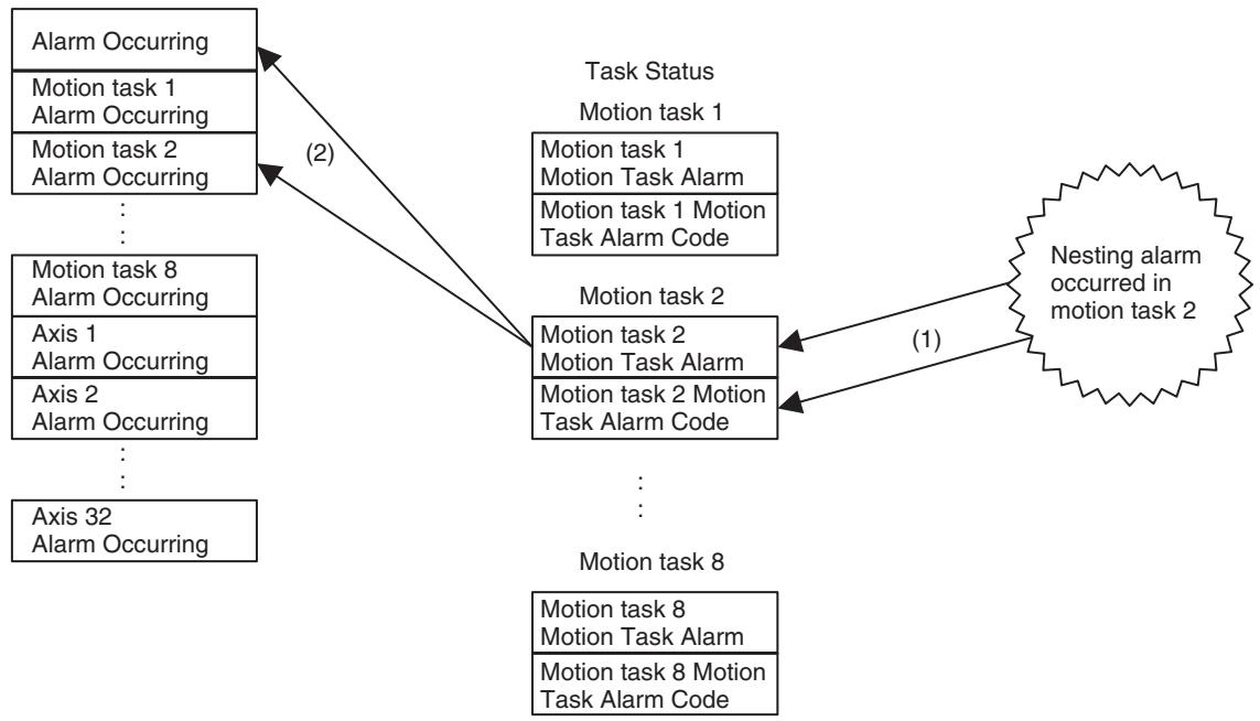
When an axis-related alarm occurs:
1,2,3...
- Axis status
The bit [Axis Alarm] is turned ON, and the alarm code is set.
- Motion task status
The bit [Motion Task Alarm] is turned ON, and the alarm code [2008h: Axis alarm generated] is set.
- Alarm identification data:
The bit [Alarm Occurring] is turned ON, the bit [Motion Task Alarm Occurring] is turned ON, and the bit [Axis Alarm Occurring] is turned ON.
(Processing Image)
Note The following diagram shows the case where the alarm [3002h: Positive direction over travel] occurs on the physical axis 5 when controlling the physical axes 4 to 6 with motion task 2.
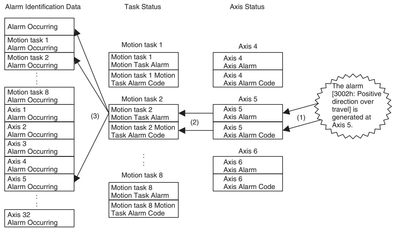
Warnings
Even, though warnings appear, they have no effect on system operations.
Warnings are output to the following bits:
| Word | Name | Probable cause and remedy |
| n+15d03 | Teaching Warning | If occurred when setting the teaching conditions:· Teaching axes have not been specified. ([Teaching Axis Setting 1-16] = [Teaching Axis Setting 17-32] = 0) Set axes to be teaching objects appropriately.There are axes among the ones specified as teaching objects in [Teaching Axis Setting 1-16] and [Teaching Axis Setting 17-32] that have not been allocated. Check if the spec-ified axes have been allocated correctly.[Teaching Address] specified is outside of the position data range. Set the address within the range of "0 to 10239".· Adding the No. of axes specified in [Teaching Axis Setting 1-16] and [Teaching Axis Set-ting 17-32] to [Teaching Address] exceeds the position data range. Set the address so that it will not exceed "10239" even after the addition.If occurred when executing teaching:· [Teaching Execution] was turned ON without setting teaching conditions. Check if [Teaching Condition Setting Completed] is ON.The bit [Command Disabled/Enabled] for any of the axes specified in [Teaching Axis Setting 1-16] and [Teaching Axis Setting 17-32] is OFF (disabled), or the bit [No Origin] for any of the axes is ON (No origin has been defined). Check the bits and correct them as needed.Adding the No. of teaching axes to [Teaching Address Monitor] exceeds the position data range. Set the address so that it will not exceed "10239" even after the addition. |
| n+17d04:d n+24d04 | Speed ClampWarning(For each motion task) | Executing override to the speed specified in a motion program caused the speed to exceed [P2AA01: Maximum rapid feed rate] of axis parameters; The speed is being lim-ited by the speed set in the parameter. Check if the override value is appropriate, or the setting of the maximum rapid feed rate is correct. (The operation does not stop.) |
| n+17d05n+24d05 | Start Warning(For each motion task) | ·A motion task was started when the bit [Deceleration Stop] or [Block Stop] had been ON. Check if the bits are OFF. ·A motion task was started with [Motion Program No.] other than 0 to 499. Check if [Motion Program No.] is within 0 to 499. ·The motion program specified with [Motion Program No.] does not exist. Create and download an appropriate program using the Support Tool, or check if the specified pro-gram No. is correct. ·The axis status bit [Command Disabled/Enabled] for the axis specified with PROG com-mand is OFF (Disabled). Check if the axis is in the command enabled state. ·The axis status bit [Axis Not Used/Used] for the axis specified with PROG command is ON (Used). Check if the other tasks being executed are using the axis. ·The axis status bit [Manual/Automatic Mode] for the axis specified with PROG com-mand is OFF (Manual). Check if the specified axis is in Automatic Mode. ·An alarm has occurred, or the unit status bit [External Forced Stop Request] is ON. Remove the cause of the alarm and reset the alarm. |
| x+32d08x+63d08 | Error CounterWarning(For each axis) | ·The error amount has exceeded the error counter warning value specified in the system parameter. Check if the specified error counter warning value is appropriate for the machine being used. (The operation does not stop.) |
| x+32d11x+63d11 | MECHATROLINKWarning(For each axis) | ·A warning has occurred on a MECHATROLINK slave. Check the applicable slave. |
11-3 Error Indicators
The LED indicator at the top of the MC Unit's front panel indicates the following errors:
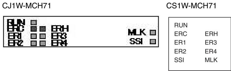
11-3-1 Errors During Initial Processing
The following table shows the errors that occur during the MC Unit's initialization processing:
| Status | LED: ON: Lit, OFF: Not lit, -: Not change, *: Custom | ||||||
| RUN | ERC | ERH | ER1 | ER2 | ER3 | ER4 | |
| Watchdog timer timeout error | OFF | OFF | OFF | OFF | OFF | OFF | OFF |
| Unit No. setting error | OFF | OFF | ON | OFF | OFF | OFF | OFF |
| PLC Unit initial processing error | |||||||
| Other CPU error | |||||||
| FINS error during initial processing | |||||||
| FINS error during restore | OFF | ON | OFF | OFF | OFF | OFF | OFF |
| Unit classification error | OFF | ON | ON | OFF | OFF | OFF | OFF |
| Hardware test error: FLASH error | OFF | ON | OFF | ON | OFF | OFF | OFF |
| Hardware test error: RAM error | OFF | ON | OFF | OFF | ON | OFF | OFF |
| Hardware test error: CPU error | OFF | ON | OFF | OFF | OFF | ON | OFF |
| Hardware test error: System software error | OFF | ON | OFF | OFF | OFF | OFF | ON |
11-3-2 Errors During Normal Operation
| Status | LED: ON: Lit, OFF: Not lit, -: Not change, *, Custom | ||||||
| RUN | ERC | ERH | ER1 | ER2 | ER3 | ER4 | |
| PLC WDT error | - | - | ON | OFF | OFF | OFF | OFF |
| PLC cyclic service monitor error | - | - | ON→OFF(Recover) | - | - | - | - |
| Bus error (PC21 bus error) | - | - | ON | - | - | - | - |
| Power failure (power failure provision) | - | - | - | - | - | - | - |
| CPU fatal error | - | - | ON | - | - | - | - |
| CPU non-fatal error | - | - | - | - | - | - | - |
| Event transmission warning generated | - | - | - | - | - | - | - |
| Panic generated | * | * | - | * | * | * | * |
| Unit level alarm generated | - | ON | - | ON | - | - | - |
| Motion task level alarm generated | - | ON | - | - | - | ON | - |
| Axis or MLK device slave node level alarm gen-erated | - | ON | - | - | - | - | ON |
| Normal operation | ON | OFF | OFF | OFF | OFF | OFF | OFF |
| System stop | OFF | - | - | - | - | - | - |
Refer to the sections 11-4 Unit-related Alarm Codes to 11-6 Axis-related Alarm Codes for details on the alarm codes.
Among these alarm codes, the code of the alarm generated first will be output to n + 11 in the allocated bit area.
11-4 Unit-related Alarm Codes
Unit-related Alarm Codes (Codes: 0001h to 00FFh)
When a unit-related alarm occurs, the following bits will indicate the status:
| Word | Address | Name |
| n+12.00 | OB03000 | Alarm Occurring |
| n+12.01 | OB03001 | Unit Alarm Occurring |
| n+15.01 | OB03031 | Unit Alarm |
| m+38 | OW0310 | Unit Alarm Code |
List of Alarm Codes
| Name | Error log | Alarm code | Cause and remedy | Timing | Rank | Reset | |
| Error code | Detail code | ||||||
| Main board code error | 0370h | 0003h | 0003h | System code area error on the main board. | Any time | System stop | Disabled |
| Main board RAM error | 0004h | 0004h | RAM error in the main board. | Any time | System stop | Disabled | |
| WDC error between the main board and sub-board. | 0005h | 0005h | WDC error was generated between the main board and sub-board. | Any time | System stop | Disabled | |
| Internal HW-WDT error | 0006h | 0006h | Internal HW-WDT error | Any time | System stop | Disabled | |
| Sub- board code error | 0013h | 0013h | System code area error on the sub-board. | Any time | System stop | Disabled | |
| User program error | 0026h | 0026h | User program area error. | Any time | System stop | Disabled | |
| CAM data error | 0027h | 0027h | CAM data area error | Any time | System stop | Disabled | |
| PLC WDT error | 0001h | 0000h | 0030h | WDT error on CPU Unit occurred. Follow the instructions in the appli-cable PLC manual. | Any time | System stop | Disabled |
| PLC cyclic ser-vice monitor error | 0002h | Monitor Time [ms] | 0031h | CPU Unit did not execute end refresh processing within cyclic service monitor time. Check end refresh prohibition in CPU system setup. If prohibited, cancel it and turn the power OFF once, and then ON again. Increase CPU Unit cyclic service monitor time and turn the power OFF once, then ON again. | Any time | Deceleration stop | Disabled |
| Bus error (PC21bus error) | 000Eh | 0000h | 0032h | Bus error occurred between CPU Unit and MC Unit. | Any time | System stop (Including event) | Disabled |
| CPU fatal error | 0015h | 0000h | 0033h | CPU fatal error occurred. Follow the instructions in the appli-cable PLC manual. | Any time | System stop | Disabled |
| CPU non-fatal error | 0016h | 0000h | --- | Follow the instructions in the appli-cable PLC manual. | Any time | --- | --- |
| Flash memory error | 0370h | 0040h | 0040h | The following data could not be written in the Flash memory. ·Protect data ·ABS origin position data ·System parameters ·Servo parameters ·Position data ·User program ·CAM data Try to save the data again. Replace MC Unit if this error persists after retrying several times. | When FLASH saving | Deceleration stop | Disabled |
| Unit deceleration stop | 0041h | 0041h | Deceleration stop input of MC Unit was turned ON. After confirming the safety in the surrounding area, turn OFF the bit [Deceleration Stop] and execute [Unit Alarm Reset]. | When deceleration stop is input. | Deceleration stop | Enabled | |
| CPU memory error | 0044h | 0044h | The following error occurred between CPU Unit and MC Unit: ·This error occurs when custom data area or custom I/O area of MC Unit is allocated to CPU's EM area, and when the specified EM areas are overlapping in executing the file memory function of CPU Unit, or when restoring the power after allocating custom data area or custom I/O area to the EM area already specified with the file memory function. ·Release the file memory function of CPU Unit, correct the allocation of the area used for the file memory function so that it does not overlap with the area used for custom data area or custom I/O area of MC Unit and reset the alarm, or correct the allocation of the area used for custom data area or custom I/O area so that it does not overlap with the area used for the file memory function and restore the power. | Any time | Deceleration stop | Enabled | |
11-5 Motion Task-related Alarm Codes
Motion task alarm codes are common for all tasks, but the alarm code output area is different for each task. The following are the alarms that occur in program execution.
Motion Task-related Alarm Code (Code: 2001h to 20FFh)
When a Motion task-related alarm occurs, the following bits will indicate the status:
| Word | Address | Name |
| n+12.00 | OB03000 | Alarm Occurring |
| n+12.03 | OB03003 | Motion Task Alarm Occurring 1 |
| n+12.10 | OB0300A | Motion Task Alarm Occurring 8 |
| n+17.00 | OB03400 | Motion task 1 Motion Alarm |
| n+24.00 | OB03470 | Motion task 8 Motion Alarm |
| m+42 | OW0360 | Motion task 1 Motion Task Alarm Code |
| m+70 | OW037C | Motion task 8 Motion Task Alarm Code |
List of Alarm Codes
| Name | Error log | Alarm code | Cause and remedy | Timing | Rank | Reset | |
| Error code | Detail code | ||||||
| No Program | 0372h-0379h | 2001h | 2001h | The sub-program to be executed with GOSUB command does not exist. Create and download an appropriate program with the Support Tool, or check if the program No. specified by GOSUB is correct. | When GOSUB is executed. | Deceleration stop | Enabled |
| Sub-program nesting error | 2002h | 2002h | There are six or more sub-program nesting levels. Check the applicable program and correct the nesting to five levels or less. | When GOSUB is executed. | Deceleration stop | Enabled | |
| Variable address error | 2003h | 2003h | Attempted to access the addresses other than "PL0000 to PL27FF" when specifying position data indirectly. Check the applicable program and correct the position data area specified indirectly to PL0000 to PL27FF. | When indirect specifi-cation is used | Deceleration stop | Enabled | |
| Divide-by-zero alarm | 2004h | 2004h | Zero division has occurred in an operation command. Check if the calculation formula or the assigned values are correct. | When operation com-mand is executed. | Deceleration stop | Enabled | |
| Operation overflow | 2005h | 2005h | Operation result cannot be stored. Check if the calculation formula or the assigned values are correct. | When operation com-mand is executed. | Deceleration stop | Enabled | |
| Program error | 2006h | 2006h | The program to be executed is corrupted. Download the applicable program with the Support Tool, save it to the F-ROM, and restore the power. The followings can be the causes of the program destruction.Destruction of data in memory due to external noiseThe power of PLC (MC Unit) was turned OFF while writing to Flash memory was in progress. | When a program is executed. | Immedi-ate stop | Disabled | |
| Axis reservation disable | 0372h-0379h | 2007h | 2007h | The axis that was declared in a program could not be reserved.The operating mode is set to Manual Mode. Make sure the applicable axis is not in use, and switch to Automatic Mode.The axis is used in another program. Wait until the program is completed, or stop the program to start ≧another program.Axes to be used in subprogram are not reserved in the main program. Reserve all the axes to be used in the subprogram with PROG in the main program.The axis that has not been declared was selected. Check if the axes to be used in the program are specified correctly. If the specification is correct, declare the axes with PROG.In parallel execution, etc., a main program tried to use the axis already declared by a subprogram. Correct the program to operate the axis after the subprogram is completed.In parallel execution, etc., a subprogram tried to declare the axis already being operated by a main program. Correct the program to call the subprogram after the block currently using the axis is completed. | When a program is executed. | Deceleration stop | Enabled |
| Axis alarm generated | 2008h | 2008h | An alarm has occurred in an axis controlled by a task. Remove the cause of the axis alarm, and reset the alarm. | When a program is executed. | Deceleration stop | Enabled | |
| Position specification error | 2009h | 2009h | The position specified with axis movement commands (except for CAM), axis operation commands, SYNCR, MOVEMODI, OFF-POS, and LATCH exceeded the allowable position range. Since the range of pulse unit system is expressed in 32-bit, the allowable range has to satisfy the following formula:-Command unit limit ≤Command unit system position ≤+Command unit limit Command unit limit [on machine] ≥2147483647 [on motor] ×P5AA04 [Command unit/1 machine rotation] × P5AA06 [on machine]9001h [No. of encoder pulses/1 motor rotation] × P5AA05 [on motor]Correct the applicable position to satisfy the formula above. When specifying with real numbers, check the setting value of the axis parameter [P5AA02: Position command decimal point position].With Traverse (MOVETRAV command): This error occurs when the operand "Winding axis rotations" = 0. Correct the program so that "Winding axis rotations" is not 0. | When a command including an operand is executed. | Deceleration stop | Enabled | |
| Speed specification error | 0372h-0379h | 200Ah | 200Ah | The following operands have exceeded the allowable range:·F (MOVEL, MOVEC, MOVETRAV), V (MOVEI, MOVET), SPEED command. Correct the applicable operands. When specifying with real numbers, check the setting value of the task parameter [P00M10: Interpolation feed decimal point position]. | When a command including an operand is executed. | Deceleration stop | Enabled |
| Time specification error | 200Bh | 200Bh | The following operands have exceeded the allowable range:·T (MOVET, CAM, SPEED, TORQUE, SPEEDDR, TORQUER, DWELL) Correct the applicable operands.·With Time-specified Positioning (MOVET command): [Speed of each axis] = Travel distance of each axis/Positioning time This error occurs when the speed specified by the above formula exceeds the axis-speed parameter [P2AA01: Maximum rapid feed rate]. Check if the setting of the parameter is correct, and if so, correct the program. | When a command including an operand is executed. | Deceleration stop | Enabled | |
| Number specification error | 200Ch | 200Ch | The following operands have exceeded the range:·C (WORK, OFFPOS), E, S (CAM, CAM-BOX, FOR) Correct the applicable operands.·With CAM, CAMBOX: This error occurs when setting the operands as [Starting data number] = [Ending data number], or when setting the operands as [Starting data number] ≥ [Ending data number] in using global general variables or position data for cam data.·When using cam table for cam data, correct the program as [Starting data number] ≠ [Ending data number]. When using global general variables or position data, correct the program as [Starting data number] < [Ending data number]. | When a command including an operand is executed. | Deceleration stop | Enabled | |
| Count specification error | 200Dh | 200Dh | The following operands have exceeded the range:·L (MOVEC, MOVETRAV, FOR), N (PAR-ALLEL, SFTR, SFTL, XFER, CLEAR) Correct the applicable operands.·With PARALLEL: This error occurs when setting the value exceeding the Max. No. of branches for the unit (the value set in the system parameter [P00002: No. of parallel branches]). Either correct (increase) the system parameter [P00002: No. of parallel branches], or correct (decrease) the No. of branches of the PARALLEL command for the motion program. | When a command including an operand is executed. | Deceleration stop | Enabled | |
| Mode specifi-cation error | 0372h-0379h | 200Eh | 200Eh | The following operand has exceeded the range. ·Q (MOVEC, MOVETRAV, MOVELINK, CAMBOX) Correct the applicable operands. | When a command including an operand is executed. | Deceler-ation stop | Enabled |
| Other oper-and error | 200Fh | 200Fh | The following operands have exceeded the range. ·K (CAM, CAMBOX) ·B (MOVELINK, CAMBOX, CONNECT, SYNC, ADDAX) ·TORQUE ·SIN, COS, ASIN, ACOS, SQT, LGN, BIN, BCD Correct the applicable operands. | When a command including an operand is executed. | Deceler-ation stop | Enabled | |
| --- | 2010h | 2010h | --- | --- | --- | --- | |
| Circular inter-polation travel distance over | 2011h | 2011h | Travel distance specified in MOVEC is too great. ·The tangent arc length has exceeded 2147483647. Check the program and correct the setting value so that it will not exceed the allowable range. (When speci-fying with variables, check if the substitu-tion formula is correct.) ·The radius has exceeded 2147483647. Check the program and correct the setting value so that it will not exceed the allow-able range. (When specifying with vari-ables, check if the substitution formula is correct.) | When MOVEC is executed. | Deceler-ation stop | Enabled | |
| Circular inter-polation radius error | 2012h | 2012h | The following instructions have been given in MOVEC. In Radius specification: The radius is specified to 0. ·Check the program and correct the radius to the value larger than 0. (When speci-f-ing with variables, check if the substitution formula is correct.) ·In Center specification: The start or end point, and the center are at the same posi-tion. Check the program and correct it so that the start or end position are not on the center. | When MOVEC is executed. | Deceler-ation stop | Enabled | |
| Control mode error | 0372h-0379h | 2014h | 2014h | ·A position control command (MOVE, etc.) or speed control command (SPEED) was executed during Torque control (TORQUE). Correct the program so that position control commands or speed control command will not be executed during TORQUE execution. ·SPEED or TORQUE was executed during position control command execution. Correct the program so that SPEED or TORQUE will not be executed during position control command execution. ·Position control commands other than MOVE was executed during SPEED command execution. Correct the program so that any position control command other than MOVE will not be executed during SPEED command execution. | When TORQUE/Position control command/SPEED is executed. | Deceleration stop | Enabled |
| --- | 2015h | 2015h | --- | --- | --- | --- | --- |
| Same axis specification multiplicity | 2016h | 2016h | ·Multiple commands were executed on the same one axis using parallel branches. (Or when a main program is trying to use the axis being used by the subprogram called by the main program, etc.) Correct the program so that multiple commands are not executed on one axis from multiple rows in the program. ·Axis movement command was executed on the axis, which is in synchronous execution as a slave axis. Correct the program so that any axis movement command will not be executed during synchronization. ·The axis, which was specified as a slave axis has been a slave axis of the different type of synchronous command. Correct the program so that any slave axis is not shared between commands. ·When a command requiring a latch input was executed, and the latch range parameter is being written, another latch-requiring command was executed on the same axis. Correct the program so that any latch-requiring command will not be executed on the same axis, or the timings do not overlap. | When a program is executed. | Deceleration stop | Enable | |
| --- | 2017h | 2017h | --- | --- | --- | --- | --- |
| Synchronous slave axis specification error | 2018h | 2018h | The axis that is specified as a slave axis has already been used as the master axis. When an axis is to be operated as a slave axis of an axis and the slave axis is to be used as a master axis of another axis, the program (to change the order of specifications) has to be arranged so that the axis is specified as a slave axis of an axis first, and then as a master of another axis. | When synchronous command is executed. | Deceleration stop | Enabled | |
| Parameter setting error | 0372h-0379h | 2019h | 2019h | <PARAM>System parameters:·Attempted to change a parameter that cannot be changed after restoring the power.·Attempted incorrect parameter setting. Check the program so that correct values can be set. (When specifying with vari-ables, check if the substitution formula is correct.)Servo parameters:·Attempted to change a parameter that cannot be changed after restoring the power.·Attempted to set incorrect setting value·Attempted to set incorrect number.·Attempted to change parameter of other tasks or undeclared axes. Check and correct the program so that cor-rect values can be set. (When specifying with variables, check if the substitution formula is correct.)·Attempted to set servo parameters on virtual axes or I/O axes.Servo parameters cannot be set on virtual axes and I/O axes. Correct the program.<LATCH>·The contents of [900Ah: Positive latch enabled range] and [900Bh: Negative latch enabled range] in the motor parameters are not written correctly.After checking the applicable axis and if the motor model is correct, transfer the motor parameters and save them to F-ROM (when individual, specify servo parameter), and restore the power.<SPEED>·The contents of [900Dh: Position loop gain] and [900Eh: Position loop gain index] in the motor parameter are not written correctly.After checking the applicable axis and if the motor model is correct, transfer the motor parameters and save them to F-ROM (when individual, specify servo parameter), and restore the power. | When PARAM,LATCH,SPEED are executed. | Deceleration stop | Enabled |
| Axis declaration error | 201Ah | 201Ah | Axis other than servo/virtual axis is included in the axis declaration.Check the parameter [P1AA02: MECHA-TROLINK-II device classification] of the applicable axis. If the setting of the parame-ter is correct, correct the program. | When PROG is executed. | Deceleration stop | Enabled | |
11-6 Axis-related Alarm Codes
Axis-related Alarm Code (Code: 3001h to 30FFh)
Axis related alarm codes are common for all axes, but the alarm code output area is different for each axis.
When an axis-related alarm occurs, the following bits will indicate the status:
| Word | Address | Name |
| n+12.00 | OB03000 | Alarm Occurring |
| n+13.00 | OB03010 | Axis Alarm Occurring 1 |
| n+14.15 | OB0302F | Axis Alarm Occurring 32 |
| x+32.00 | OB04400 | Axis 1 Axis Alarm |
| x+63.00 | OB045F0 | Axis 32 Axis Alarm |
| d+32 | OW0480 | Axis 1 Alarm Code |
| d+125 | OW04DD | Axis 32 Alarm Code |
List of Alarm Codes
| Name | Error log | Alarm code | Cause and remedy | Timing | Rank | Reset | |
| Error code | Detail code | ||||||
| --- | 037Ah-0399h | 3001h | 3001h | --- | --- | --- | --- |
| Over travel, positive direc-tion | 3002h | 3002h | The over travel signal in positive direction has turned ON during axis movement. After resetting the alarm, attempted to operate the axis in the positive direction with the positive direction over travel sig-nal ON. Move the axis in the negative direction manually. | Any time | Immediate stop | Enabled | |
| Over travel, negative direction | 3003h | 3003h | The over travel signal in negative direction has turned ON during axis movement. After resetting the alarm, attempted to operate the axis in the negative direction with the negative direction over travel sig-nal ON. Move the axis in the positive direction manually. | Any time | Immediate stop | Enabled | |
| Over travel, both direc-tions | 3004h | 3004h | The over travel signals in both directions have turned ON during axis movement or when the axis was about to move. After resetting the alarm, attempted to operate the axis with the over travel sig-nals in both directions ON. Check if the over travel signals for both directions are wired correctly. | Any time | Servo OFF | Enabled | |
| Software limit, positive direc-tion | 3005h | 3005h | The axis entered the software limit area in positive direction during axis movement with the origin defined. Check if the setting value of the axis parameter [P3AA02: Positive direction software limit] is correct. (The error may occur when executing circular interpolation right on the software limit values.) If the setting value is incor-rect, set a larger limit value. When the value is correct, correct the program or travel distance of the axis. | Any time | Decelera-tion stop | Enabled | |
| Software limit negative direction | 037Ah-0399h | 3006h | 3006h | The axis entered the software limit area in negative direction during axis movement with the origin defined. Check if the setting value of the axis parameter [P3AA02: Negative direction software limit] is correct. (The error may occur when executing circular interpolation right on the software limit values.) If the setting value is incorrect, set a larger limit value. When the value is correct, correct the program or travel distance of the axis. | Any time | Deceleration stop | Enabled |
| Servo OFF | 3007h | 3007h | The axis that received a movement command is in Servo OFF state. (In operations with programs, this alarm will occur when the applicable axis is specified at the beginning of the block and a movement command is executed for the axis that is in Servo OFF state.) Switch the axis to Servo lock state.Servo OFF was executed for the axis receiving a movement command.Do not execute Servo Unlock during axis movement. | When axis movement starts/ During axis movement. | Servo OFF | Enabled | |
| Synchronous communications alarm | 300Ah | 300Ah | An error was occurred in the MECHA-TROLINK synchronous communications. The followings are the possible causes:Disconnection, breakage of MECHA-TROLINK cableCheck the MECHATROLINK cable.Communications error caused by noise Remove the cause of the noise.When this error persists even after providing these remedies, the Driver (NS115) or MC Unit may be broken. Replace the broken one with a new unit. | Any time | Servo OFF | Enabled | |
| Communications alarm | 300Bh | 300Bh | Detected MECHATROLINK communications errors twice in a row. Or the No. of error detections specified in [P1AA06: MECHATROLINK-II communications error detection setting] has been exceeded. The followings are the possible causes:Disconnection, breakage of MECHA-TROLINK cableCheck the MECHATROLINK cable.Communications error caused by noise Remove the cause of the noise.When this error persists even after providing these remedies, the Driver (NS115) or MC Unit may be broken. Replace the broken one with a new unit. | Any time | Servo OFF | Enabled | |
| Command timeout | 037Ah-0399h | 300Ch | 300Ch | A MECHATROLINK command could not be completed within a fixed period of time (10 seconds). The followings are the possible causes:Disconnection, breakage of MECHAN-TROLINK cableCheck the MECHATROLINK cable.Communications error caused by noiseRemove the cause of the noise.When this error persists even after providing these remedies, the Driver (NS115) or MC Unit may be broken. Replace the broken one with a new unit. | Any time | Servo OFF | Enabled |
| Absolute encoder error | 300Dh | 300Dh | Data from the ABS encoder could not be processed normally.Initial multi-turn value exceeds the multi-turn limit.Set the same value in the driver parameter [Pn205: Multi-turn limit setting] and the motor parameter [900C: Multi-turn limit].After the setting is completed, restore the power, reset the alarm, and perform the origin setting.After origin setting, the following values related to B/A were changed.Note B = No. of encoder pulses × P5AA05A = P5AA04 × P5AA06B/A is integer calculation and the result is to be reduced.After the change was made (saving to F-ROM), restore the power, reset the alarm, and perform origin setting.The multi-turn limit value in the driver parameter or the motor parameter was changed after origin setting.After the change was made (saving to F-ROM), restore the power, reset the alarm, and perform origin setting. (When the multi-turn value of the driver parameter was changed, make sure to perform "Absolute encoder multi-turn amount setting change" on the driver.)Servo driver is set as an incremental encoder. Set the driver parameter Pn002 digit No. 2 to "0" (used as an absolute encoder) and restore the power.Disconnection, breakage of encoder cableCheck the encoder cable.Communications error caused by noiseRemove the cause of the noise.When this error persists even after providing these remedies, the encoder or MC Unit may be broken. Replace the broken one with a new unit. | When synchronous communications starts | Servo OFF | Enabled | |
| Over travel already ON | 037Ah-0399h | 300Eh | 300Eh | The limit switch in the direction of the search was already ON when a one direction-mode origin search was executed. Check the status of the limit switch in the origin search start direction. Also check and correct the origin search start position. (See 8-4 Origin Search Operations (page 536) for details.) | In origin search | Immediate stop | Enabled |
| Origin proxim-ity reverse alarm | 300Fh | 300Fh | The limit reversal mode origin search cannot be performed because the limit switch in the direction of the search turned ON while the search was reversing. Check the status of the limit switch in the origin search start direction. And check and correct the positions of the origin proximity limit switch and the limit switch. | In origin search | Immediate stop | Enabled | |
| Over travel reverse alarm | 3010h | 3010h | The limit reversal mode origin search cannot be performed because the limit switch or deceleration LS in the opposite direction of the search turned ON while the search was reversing due to over travel signal ON in the direction of the origin search. Check the status of the limit switch in the origin search start direction. And check and correct the positions of the origin proximity limit switch and the limit switch. | In origin search | Immediate stop | Enabled | |
| Synchronous slave axis speed over | 3011h | 3011h | With synchronous commands (MOVELINK, CAMBOX, CONNECT,SYNC,ADDAX), the speed of the slave axis exceeded the speed specified in [P2AA01: Maximum rapid feed rate]. Check if the setting value in the parameter is correct. If it is correct, correct the program. With CAMBOX, check also the displacement of the CAM data. | When a program is executed | Deceleration stop | Enabled | |
| Excessive error alarm | 3012h | 3012h | Position error exceeded the setting value of the axis parameter [P3AA06: Position error alarm detection value]. Check if the set value is appropriate for the system configuration and correct it as needed. When the value is correct, check the follow-ings: ·Breakage of encoder cable ·Malfunction caused by noise ·Unadjusted servo system ·Unadjusted or unprepared machine sys-tem These causes are to be removed. | Any time | Servo OFF | Enabled | |
| MECHA-TROLINK-II slave axis error 1 | 3013h | 3013h | An error occurred on a MECHATROLINK-II slave axis. Check the MECHATROLINK slave of the applicable node No. and remove the cause of the error. Slave alarm codes are stored in the error log in the MC Unit. | Any time | Servo OFF | Enabled | |
| Axis classification error | 037Ah-0399h | 3015h | 3015h | Attempted to execute a command that cannot be executed as an axis. (The command that requires an external signal (MOVEI, etc.) was executed on the virtual axis, or the winding axis of MOVETRAV is not set as an unlimited length axis, etc.)Correct the applicable parameters or program. | When a command is executed. | Deceleration stop | Enabled |
| No origin proximity signal | 3016h | 3016h | During an origin search in the limit reversal mode, there was no deceleration limit switch in between over travel of both directions.Provide the origin proximity limit switch, or check if the limit switches themselves or wiring is normal. | In origin search | Immediate stop | Enabled | |
| Origin proximity and over travel simultaneously ON | 3017h | 3017h | During an origin search, the deceleration limit switch and the over travel in direction of the search were turned ON simultaneously.Check if the origin proximity signal, or over travel signals for both directions are wired correctly. | In origin search | Immediate stop | Enabled | |
| No origin signal | 3018h | 3018h | During an origin search, the over travel signal turned ON while waiting for the origin signal (while waiting for the rise of phase-Z after the fall (ON to OFF) of the origin proximity limit switch).Check if the settings of the axis parameter [P4AA06: Origin determine signal] and the servo parameter [Pn511: Input signal select 5] are correct (if the applicable signal is enabled).If the settings are correct, check the followings:Problem on Phase-Z of the encoderBreakage of encoder cableToo small distance between the origin proximity limit switch and the limit switch These causes are to be removed. | In origin search | Immediate stop | Enabled | |
| Excessive speed command | 037Ah - 0399h | 3019h | 3019h | The axis speed has exceeded maximum rapid feed rate during the following command execution: • MOVEL (Axes except for the one with the longest travel distance) • MOVEC (Linear axis: if not specified with the tangential speed of the circular interpolation portion.) • MOVETRAV (Traverse axis) • CAM Check if the speed set in [P2AA01: Maximum rapid feed rate] is correct. If it is not correct, set a higher speed. If it is correct, lower the feed rate of the program or lower the speed using override. | When a program is executed | Deceleration stop | Enabled |
| Counter latch resource violation | 301Ah | 301Ah | With DATUM, MOVEI, MOVELINK, CAM-BOX, SYNC, and LATCH commands, attempted to execute the functions simultaneously that require the counter latch. Check the axis specified for the Latch and correct the program so that there are no redundant specifications (executing LATCH command on the axis already executing LATCH command, executing LATCH command on the axis waiting for the synchroni-zation start conditions to be satisfied, or etc.). | When a command that needs counter latch function is executed | Deceleration stop | Enabled | |
| Gear ratio range error | 3040h | 3040h | Relations between the No. of encoder pulses and command unit is not normal. When the following expression is not satisfied, the error will occur: 1/7FFFFFFh ≤ B/A ≤ 7FFFFFFH Note B = No. of encoder pulses × P5AA05 A = P5AA04 × P5AA06 B/A is integer calculation and the result is to be reduced. Set the parameters so that the formula above is satisfied. | Real axis: When connected Virtual axis: When power is ON | Servo OFF | Disabled | |
11-7 MLK Device Alarm Codes
MLK (MECHATROLINK-II) device alarm codes are recorded in the following two stages.
1,2,3... 1. The generic alarm code for MLK devices, 3013h, is set along with the information in the following table.
| Word | Address | Name |
| n+12.00 | OB03000 | Alarm Occurring |
| n+13.00 | OB03010 | Axis Alarm Occurring 1 |
| n+14.15 | OB0302F | Axis Alarm Occurring 32 |
| x+32.00 | OB04400 | Axis 1 Alarm |
| : | : | : |
| x+63.00 | OB045F0 | Axis 32 Alarm |
| d+32 | OW0480 | Axis 1 Alarm Code (3013h) |
| : | : | : |
| d+125 | OW04DD | Axis 32 Alarm Code (3013h) |
- A "detail code" is then stored in the error log to provide details for the MLK device.
| Name | Error log | Cause and remedy | Timing | Rank | Reset | |
| Error code | Detail code | |||||
| Depending on the device | 037Ah to 0399h | 4000h + Alarm code of each device | Depending on the device. Follow the directions of the applicable manuals. | Depending on the device | Depending on the device | Enabled |
- Error Codes
Error code 037Ah is for the MLK device allocated physical axis 1, and error code 0399h is for the MLK device allocated physical axis 32.
- Detail Codes
The alarm code for each device plus 4000h is stored for the detail code.
For details of the alarm codes, refer to the following manuals of Yaskawa Electric Corporation.
- -II Series SGDH MECHATROLINK-II Application Module User's Manual, Model: JUSP-NS115 (Manual No. SIEPC71080001*)
- Machine Controller MP900 Series MECHATROLINK System User's Manual (Manual No. SIEZ-C887-5.1)
If the axis for which the error occurred is for a Servo Driver, the Servo is turned OFF to stop the axis. Alarms that cannot be reset on the slave side will be detected again even if the Alarm Reset Bit is used to reset the alarm.
11-8 Servo DriverWarnings
The W-series Servo Drivers provide various warnings. The warning, causes, and corrections are given in the following table.
| Display | Name | Cause and correction |
| A.91 | Overload | This warning is given before an overload alarm (A.71 or A.72) is reached. An alarm is likely to occur if operation is continued without any changes. Check the load to see if it is suitable. |
| A.92 | Regenerative overload | This warning is given before a regeneration overload alarm (A.32) is reached. An alarm is likely to occur if operation is continued without any changes. Check the load to see if it is suitable. |
| A.94 | Data setting warning | A setting was made out of range using MECHATROLINK-II communications. Check the data number and data setting range specified with the PARAM command or the Support Tool running on a computer.It is possible that settings for the Servo Driver parameter, option monitor, are incorrect. For a W-series Servo Driver, check that Pn813 = 0032 (hex). For a Servo Driver with built-in communications, check that Pn824 = 0023 (hex) and Pn825 = 0024 (hex). If they are not, correct the values. |
| A.95 | Command warning | The command received via MECHATROLINK-II communications could not be executed under the current conditions. This warning will occur under conditions like the following:An attempt was made to lock the servo when the Servo Driver's main circuit was OFF.An attempt was made to read or write Servo Driver parameters using CX-Motion-MCH while communications were in progress for the Digital Operator or W-Mon.The same station address (node address) is set for more than one node.Power to the main circuit was turned OFF during positioning. |
| A.96 | Communications warning | A communications error has occurred. If a communications warning occurs twice consecutively, a communications alarm (A.E6) will occur. This warning will occur under conditions like the following:The same station address (node address) is set for more than one node.Vibration, Shock, or Peripheral Device NoiseTake the following countermeasures against vibration, shock, and peripheral device noise.Vibration/Shock CountermeasuresMake sure the communications connector is inserted properly.Check for vibration and shock in the equipment or peripheral devices when A.96 occurs. If there is any suspect vibration or shock, take measures in the equipment so that the vibration or shock is not transmitted to the motion control system.Remove any stress being applied to the cables in bundling or wiring them.Noise CountermeasuresAn noise-isolating transformer is installed for each system to separate power supply circuits so that noise does not affect other systems. Separate power supplies are installed as follows:Do not use a power supply for more than one system.Use wiring with minimal voltage drop from the power reception system to the equipment.Wire the system using separate paths from other systems.Use an independent ground for the secondary side of the transformer with an independent ground pole.Separate power lines as far as possible from signal lines to prevent inductive noise (30 cm min. recommended).Place power lines in a metal conduit pipe and ground the pipe.Use shielded cables, twisted-pair cables, etc., for signal lines and keep wiring distances as short as possible.Do not bundle power lines together with signal lines or run them parallel with signal lines.Ground the common of the shield in shielded cables at only one point. Do not create loops by connecting more than one point.Ground to 100 Ω or less.To reduce common impedance, connect ground wires from the equipment to the ground plate in star connections.Do not use crossover wiring to wire grounds. |
11-9 Error Log
Up to twenty errors detected and notified on the MC Unit can be stored in the system variable in the MC Unit as the error log.
The system variables (error log) will be cleared when the power is restored or the Unit is restarted. To store the error log, use the IORD instruction to make the CPU Unit read and store it.
The error log is composed of 2 words for the number of stored records, and 120 (6 words × 20 error records) words.
11-9-1 Area Configuration
| Variable addresses | IORD addresses | Name | Description |
| SW0010 | 3008h | Error log: No. of stored records | Outputs the number of errors occurred after the power ON. 0-20 |
| SW0011 | Error log: No. of actual records | Outputs the number of errors occurred after the power ON. 0-64000 | |
| SW0012 | 3009h | Error log 1: Error code | Outputs the code of the error. |
| SW0013 | Error log 1: Detailed data | Outputs detailed data of the error. | |
| SW0014 | 300Ah | Error log 1: Minute, Second | Outputs minutes and seconds of the time when the error was generated. |
| SW0015 | Error log 1: Day, Hour | Outputs days and hours of the time when the error was generated. | |
| SW0016 | 300Bh | Error log 1: Year, Month | Outputs year and month of the time when the error was generated. |
| SW0017 | Reserved | Reserved | |
| : | |||
| : | |||
| SW0084 | 3042h | Error log 20: Error code | Outputs the code of the error. |
| SW0085 | Error log 20: Detailed data | Outputs detailed data of the error. | |
| SW0086 | 3043h | Error log 20: Minute, Second | Outputs minutes and seconds of the time when the error was generated |
| SW0087 | Error log 20: Day, Hour | Outputs days and hours of the time when the error was generated. | |
| SW0088 | 3044h | Error log 20: Year, Month | Outputs year and month of the time when the error was generated. |
| SW0089 | Reserved | Reserved | |
- Errors are recorded up to 20 starting from the oldest error stored as Error log 1.
- From the 21^st error on, the oldest error is deleted and the newest is overwritten. For example, the 21^st error is stored in the Error log 1, the 22^nd error is stored in the Error log 2, and so on.
- The newest error is stored in the Error log with the number indicated by the remainder of dividing SW0011: Error log No. of actual records by 20.
Error code
The error codes are classified into the CPU errors and MC Unit errors.
CPU Error Codes
| Error code (Hex) | Error name | Detailed code | Cause | |
| 1st byte | 2nd byte | |||
| 0001 | CPU WDT error | 00 | 00 | The watchdog timer alarm occurred on CPU Unit.Provide remedy following instructions in the manual of the CPU Unit. |
| 0002 | CPU cyclic service monitor error | Monitor time (ms) | Time out of the cyclic monitor time.The followings are the possible causes:End refresh is prohibited on CPU Unit.The scan time of CPU Unit is too long.Remedies:Enable end refreshSet the longer cyclic monitor time. | |
| 000E | CPU bus error | 00 | 00 | CPU Unit Bus error |
| 0015 | Fatal CPU error | 00 | 00 | Fatal error occurred on CPU Unit.Check if MC Unit is mounted on the backplane correctly. If the error persists even after the checking and correction, CPU Unit or the back-plane may be broken. Replace it as needed. |
| 0016 | Non-fatal CPU error | 00 | 00 | Non-fatal error occurred on CPU Unit.Provide remedy following instructions in the manual of CPU Unit. |
| 0108 | Routing error | In a command:When SNA < 80 HexD7:OFFD6 to D0:SNSA> = 80HexD7:OFFD6 to D0:0In a response:When DNA<80HexD7:OND6 to D0:DNADNA> = 80HexD7:OND6 to D0:0 | D7 to D0:SA1D7 to D0:SNSA(= 80Hex)D7 to D0:DA1D7 to D0:DNA(DNA> = 80Hex) | Transfer not possible because there is no Unit for the specified unit numberNormally, this error does not occur. If it should occur, report to OMRON. |
| 010D | Routing error | Transfer not possible because the destination address in the routing table has not been set.Normally, this error does not occur. If it should occur, report to OMRON. | ||
| 010E | Routing error | Transfer not possible because of a routing table error.Normally, this error does not occur. If it should occur, report to OMRON. | ||
| 0118 | Incorrect packet error | An incorrect packet has been transferred.Normally, this error does not occur. If it should occur, report to OMRON. | ||
| 0124 | Routing error | Routing not possible because the maximum frame length has been exceeded.Normally, this error does not occur. If it should occur, report to OMRON. | ||
| 0601 | Panic generated | Panic data | Set if trap processing has been executed.Normally, this error does not occur. If it should occur, report to OMRON. | |
MC Unit Error Codes
In the detailed codes of each error, the alarm code of each error is set. Therefore, all the alarms will be stored in the error log.
| Error code (Hex) | Error name | Detailed code | Cause | |
| 1st byte | 2nd byte | |||
| 0370 | Unit-related alarm | Code of the alarm that has occurred | An alarm related to the Unit has occurred. The same remedy of the corresponding alarm code should be provided. | |
| 0371 | Reserved | |||
| 0372 | Motion task 1 Alarm | Code of the alarm that has occurred | An alarm related to motion task 1 has occurred. The same remedy of the corresponding alarm code should be provided. | |
| 0373 | Motion task 2 Alarm | Code of the alarm that has occurred | An alarm related to motion task 2 has occurred. The same remedy of the corresponding alarm code should be provided. | |
| : | : | Code of the alarm that has occurred | : | |
| 0379 | Motion task 9 Alarm | Code of the alarm that has occurred | An alarm related to motion task 8 has occurred. The same remedy of the corresponding alarm code should be provided. | |
| 037A | Axis 1 Alarm | Code of the alarm that has occurred | An alarm related to axis 1 has occurred. The same remedy of the corresponding alarm code should be provided. | |
| 037B | Axis 2 Alarm | Code of the alarm that has occurred | An alarm related to axis 2 has occurred. The same remedy of the corresponding alarm code should be provided. | |
| : | : | Code of the alarm that has occurred | : | |
| 0398 | Axis 31 Alarm | Code of the alarm that has occurred | An alarm related to axis 31 has occurred. The same remedy of the corresponding alarm code should be provided. | |
| 0399 | Axis 32 Alarm | Code of the alarm that has occurred | An alarm related to axis 32 has occurred. The same remedy of the corresponding alarm code should be provided. | |
SECTION 12
Maintenance and Inspection
This section describes the maintenance and inspection procedures required to keep the CJ1W-MCH71 and CS1W-MCH71 Motion Control Units in optimum condition.
12-1 Routine Inspection 660
12-1-1 Inspection Points 660
12-1-2 Handling Precautions 661
12-1-3 Procedure for replacing an MC Unit. 661
12-1-4 Procedure for replacing a Servo Driver. 662
12-1-5 Procedure for replacing the NS115 662
12-1 Routine Inspection
In order for your MC Unit to continue operating at optimum condition, periodic inspections are necessary.
12-1-1 Inspection Points
The main components of the Unit are semiconductors and have a long service life, but depending on the operating environment, there may be more or less deterioration of these and other parts. A standard inspection schedule is once every six months to one year. More frequent inspections may be advisable depending on the operating environment. Maintain the inspection schedule once it has been set. Checks to be sure that the power supply, ambient temperature, humidity, and other specifications are within the specifications. Be sure that these are no loose screws and that all battery and cable connections are secure. Clean any dust or dirt that has accumulated.
Periodic Inspection Items
| No. | Item | Inspection points | Criteria | Remarks |
| 1 | I/O Power Supply | Measure the voltage variations at the I/O power supply terminal block. Do they meet the standard? | DC24V: DC21.6 to 26.4V | With a voltage tester, check between the terminals and make sure that the power supply falls within the acceptable range. |
| 2 | Environment conditions | Is the ambient temperature within the acceptable range? (When used in a panel, the ambient temperature inside the panel must be checked.) | 0-55 degrees Celsius | With a thermometer, check the ambient temperature inside the panel and make sure that it falls within the acceptable range. |
| Is the ambient humidity within the acceptable range? (When used in a panel, the ambient humidity inside the panel must be checked.) | 10 to 90%RH (with no condensation) | With a hydroscope, check the ambient humidity inside the panel and make sure that it falls within the acceptable range, and check if there is possibility of condensation due to sudden temperature change. | ||
| Is the Unit exposed to direct sunlight? | It must not be exposed to direct sunlight. | Shield the Unit from direct sunlight. | ||
| Is there any accumulation of dust (especially iron dust) or salts? | There must be none of these present. | Remove any accumulation of dust (especially iron dust) or salts and protect against them. | ||
| Is the Unit exposed to any spray of water, oil, or chemicals? | It must not be exposed to any of these. | Protect the Unit from water, oil, and chemicals. | ||
| Is the location subject to corrosive or flammable gases? | The Unit must not be exposed to these. | Check for smells or use a gas sensor. | ||
| Is the location subject to shock or vibration? | The amount of shock or vibration must be within the acceptable ranges given in the specifications. | Install a cushion or other device to reduce shock and vibration. | ||
| Is the location near any source of noise? | There must be no noise. | Move the noise source away from the Unit or apply countermeasures. | ||
| 3 | Installation and wiring | Is the MC Unit securely mounted? | There must be no looseness. | With a Phillips screwdriver, tighten all mounting screws. |
| Are the cable connectors properly inserted and locked? | Carefully insert and lock all cable connectors. | |||
| Are there any loose screws in the external wiring? | With a Phillips screwdriver, tighten all screws in the external wiring. | |||
| Are any crimp terminals for external wiring too close together? | There must be sufficient space between them. | Do a visual check and separate the terminals as required. | ||
| Are any external cables about to break? | There must be no external abnormalities. | Do a visual check, and connect or replace cables as required. |
Required Tools
Required tools
- Phillips screwdriver
- Voltage tester or digital voltage meter
- Industrial alcohol ad clean cotton cloth
Equipment that may be required depending on the case
- Oscilloscope
- Synchoscope
- Thermometer, hydrometer
12-1-2 Handling Precautions
- Turn OFF the power before replacing the Unit.
- If a Unit is found to be faulty and is replaced, check the new Unit again to ensure there are no errors.
- When returning a faulty Unit for repair, make a detailed record of the Unit's malfunction and take it together with the Unit to your nearest OMRON office or sales representative.
- If a contact is not good, put some industrial alcohol on a clean cotton cloth and wipe the surface. After doing this, install the Unit.
- Before restarting operation, transfer the required programs, position data, and system parameters to the MC Unit that was changed, and save them to the flash memory.
12-1-3 Procedure for replacing an MC Unit
Follow the procedure below when it is necessary to replace an MC Unit.
1,2,3...
- Make a note of the unit number of the MC Unit to be replaced.
- To retain the status and settings of the MC Unit that is to be replaced, execute the backup operation of the CPU Unit to save the MC Unit's data, parameters, or programs into a memory card. For the operation procedure, refer to the SYSMAC CS/CJ Series Programmable Controllers Programming Manual (W394).
- Turn OFF the power supply.
- To facilitate rewiring, carefully label the cables that are to be disconnected.
- Replace the MC Unit, and reconnect the wiring as before.
- Set the unit number for the MC Unit.
-
Turn ON the power supply to the PLC.
-
Read the data, parameters, or programs that are saved in the memory card to the MC Unit through the CPU Unit's backup operation.
- Turn OFF the power supply to the PLC.
The replacement of the MC Unit is completed.
12-1-4 Procedure for replacing a Servo Driver
Follow the procedure below when it is necessary to replace a Servo Driver.
1,2,3... 1. Turn OFF the PLC and the Servo Driver.
- To facilitate rewiring, carefully label the cables that are to be disconnected.
- Replace the Servo Driver, and reconnect the wiring as before.
- Turn ON the Servo Driver and PLC.
- Set the bit [Servo Parameter Save] ON using the Programming Console or the ladder program on PLC to save servo parameters in the MC Unit into the Servo Driver.
- Turn OFF the PLC and the Servo Driver.
The replacement of the Servo Driver is completed.
12-1-5 Procedure for replacing the NS115
Follow the procedure below when it is necessary to replace the NS115.
1,2,3... 1. Turn OFF the PLC and the Servo Driver.
- To facilitate rewiring, carefully label the cables that are to be disconnected.
- Replace the NS115, and reconnect the wiring as before.
- Turn ON the Servo Driver and PLC.
- Turn ON the bit [Servo Parameter Save] using the Programming Console or the ladder program on PLC to save NS115 parameters in the MC Unit into the new NS115.
The Servo Driver parameters will also be transferred from the MC Unit and saved at this time.
- Turn OFF the PLC and the Servo Driver.
The replacement of the NS115 is completed.
Appendix A
Performance
| Item | Performance (ms) | Description |
| Power ON startup time | Approximately (13 + 0.1 × No. of physical axes) × 1000 | Time from turning ON the power until the MC Unit becomes ready to accept manual operation commands, such as Servo Lock commands. Virtual axes are not included in the physical axes. |
| PLC scan time | Tc | Cycle time of the PLC |
| Unit cycle | Tm = 1, 2, 3, 4, 6, or 8 | This is the time required to execute a motion task when there is only one motion task. Refer to Calculation Method for Unit Cycle on page 665. |
| Communications cycle | Ts = 1, 2, 3, or 4 | Communications cycle of MECHATROLINK-II. Refer to Calculation Method for Communications Cycle on page 665. |
| Cycle time extension time | No. of motion tasks × 6 × 0.001 + No. of axes × 8 × 0.001 + No. of allocated general I/O words × 0.001 + 0.6 | The cycle time is extended by this amount of time for each MC Unit mounted to the same PLC. |
| Servo command response time | •W Series + NS115 Td = 0.625 •W Series with built-in MECHATROLINK-II Td = 0.425 | Time required before outputting current to the motor after the Servo Driver receives a command via MECHATROLINK-II. |
| Operation startup time for automatic operation | Min.: Tc + Tm + 2Ts + Td Max.: 2Tc + 3Tm + 2Ts + Td | Time from enabling the start signal allocated to an Input Unit of the PLC until outputting current to the Servo Driver when there is only one motion task and all axes are being operated. |
| Operation startup time for manual operation | Min.: 0.7 + Tm + 2Ts + Td Max.: Tc + 3Tm + 2Ts + Td | Time from turning ON the start bit (JOG bit) from a ladder program in the PLC until outputting current to the Servo Driver. |
| Offset per axis (interpolation, independent operation) | 0 | • Time offset caused when interpolation is performed with one motion task. There is no offset between axes. • Time offset caused when motion tasks with one axis each are started simultaneously. There is no offset between axes. |
| Status refresh offset per axis | 0 | Offset between refresh cycles between axes in refreshing the status of the controlled axes (present position, speed, input signals, etc.). The status of all axes is always refreshed at the same time, so there is no offset. |
| Minimum operation time | Tm | Minimum operation time required to stay in Pass Mode. The same as the Unit Cycle. |
| Minimum traverse reversal time | Tm | Minimum time required for reversal operation of traverse command. The same as the Unit cycle. |
| External input response time (Unit Built-in general input) | Tm or less | Time from accepting the Unit built-in general input until it is reflected to input variables. It is less than Unit cycle. |
| External input response time (Unit Built-in deceleration stop input) | Min.: 2Ts + Tm + Td Max.: 2Ts + 2Tm + Td | Time from receiving deceleration stop input until current is output to the Servo Motor. |
| External input response time (CW/CCW limit origin proximity input) | Min.: 4Ts + 2Tm + Td Max.: 4Ts + 3Tm + Td | Time from when the Servo Driver detects the input until current is output to the Servo Motor. |
| Slave input response time (MECHA-TROLINK slaves) | Min.: 4Ts + 2Tm + TdMax.: 4Ts + 3Tm + Td | Time from when a signal is input to the slave I/O Unit and the I/O Unit reads the input until current is output to the Servo Motor. |
| Feedback position synchronization delay (MECHATROLINK slaves) | 4Ts + 2Tm + Td | Time until current is output to the Servo Motor of the slave axis when synchronizing the MECHA-TROLINK slave feedback position. |
| Counter latch startup time when start position and end position are specified | ·When Tm = 1 or 2Min.: 3Ts + 5Tm + 104Max.: 3Ts + 5Tm + 124·When Tm = 3 to 8Min.: 3Ts + 5Tm + 144Max.: 3Ts + 5Tm + 164 | Time until a counter latch can be executed after starting execution of a LATCH command. Refer to Calculation Method for the Counter Latch Startup Time on page 666. |
| Counter latch startup time when start position and end position are not speci-fied | 3Tm + 3Ts + 4 | Time until a counter latch can be executed after starting execution of a LATCH command. Refer to Calculation Method for the Counter Latch Startup Time on page 666. |
| PARAM command execution time for Servo Driver parameters | ·When Tm = 1 or 2Min.: 2Tm + 60Max.: 2Tm + 80·When Tm = 3 to 8Min.: 2Tm + 80Max.: 2Tm + 100Decimal fractions in division results are rounded up. | Time required to complete PARAM command execution when using the PARAM command to change Servo Driver parameters. |
| PARAM command execution time for other parameters | Min.: 2Tm + 20Max.: 2Tm + 40Decimal fractions in division results are rounded up. | Time required to complete PARAM command execution when using the PARAM command to change parameters other than Servo Driver parameters. |
| IORD/IOWR instruction execution time for Servo Driver parameters | ·When Tm = 1 or 2Min.: 2Tm + Tc + 60.7Max.: 4Tm + 3Tc + 80·When Tm = 3 to 8Min.: 2Tm + + Tc + 80.7Max.: 4Tm + 3Tc + 100Decimal fractions in division results are rounded up. | Time required to complete PARAM command execution when using the IORD/IOWR instruc-tion to transfer Servo Driver parameters. |
| IORD/IOWR instruction execution time for other parameters | Min.: 2Tm + Tc + 20.7Max.: 4Tm + 3Tc + 40Decimal fractions in division results are rounded up. | Time required to complete PARAM command execution when using the IORD/IOWR instruc-tion to transfer parameters other than Servo Driver parameters. |
| SPEED instruction execution time | ·When Tm = 1 or 2Min.: 3Tm + 60Max.: 3Tm + 80·When Tm = 3 to 8Min.: 3Tm + 80Max.: 3Tm + 100Decimal fractions in division results are rounded up. | Time required to output a speed command in the direction of the specified speed command when changing the speed by executing the SPEED instruction (including execution while the SPEED instruction is already being executed). |
Processing Cycle of MC Unit
The MC Unit has both a control cycle for the entire Unit and a communications control cycle. The system software in the MC Unit calculates each control cycle, and it operates using a Unit cycle: communications cycle ration of 1:1 or 2:1.
The calculation method for each control cycle is described below.
- The Unit cycle is calculated.
-
The Communication Cycle is calculated.
-
The ratio between the Unit cycle and communications cycle is adjusted.
Calculation Method for Unit Cycle
Basic formula for calculating Unit Cycle is shown below:
Unit Cycle [ s] = (85× No. of axes) ^+ (120× No. of motion tasks × No.of parallel branches) ^+ (0.3× No. of general allocated words) +200 - - - (1)
- No. of axes: No. of axes allocated in [P1AA01:Physical axis setting] (Sum of virtual and actual axes)
- No. of Motion tasks: P00001 [No. of Motion tasks]
- No. of parallel branches: P00002 [No. of parallel branches]
- No. of general allocated words: No. of Allocated words to be used as general purpose I/O (Sum of inputs and outputs)
Note for P00003 [Unit Scan time]
When P00003 [Unit Scan time] is greater than the result of the formula (1), the formula (2) below is to be used. Unit Cycle [ s] = P00003 × 1000 - - - (2)
Determining Unit Cycle
The Unit Cycle can be determined by rounding up the Unit Cycle [μs] that was found using formula (1) or (2) to 1 ms, 2 ms, 3 ms, 4 ms, 6 ms, or 8 ms.
If the unit cycle time exceeds 8 ms, 8 ms is set.
Calculation Method for Communications Cycle
Basic formula for calculating Communications Cycle is shown below:
Communications Cycle [ s] = ((No. of allocated nodes + No. of Retries) × 102.7 + 19.2) × 1.1 - - (3)
- No. of Allocated Node: No. of MECHATROLINK-II slaves (only physical axes) allocated in [P1AA01: Physical Axis Setting]
- No. of Retries: No. of retries specified in [P00009: MECHATROLINK No. of retrial nodes setting] (= 0-7).
If the Communications cycle was less than 1ms, the formula (4) below is to be used.
Communications cycle [ s] = 1000 - - (4)
Determining Communications Cycle
The Communications Cycle can be determined by rounding up the Communications Cycle [μs] that was found by the formula (3) or (4) to 1 ms, 2 ms, 3 ms, or 4 ms.
If the communications cycle time exceeds 4 ms, 4 ms is set.
Note The formula used in this section applies when P00004 bit 09 is 1 for a CJ1W-MCH71 or CS1W-MCH71 Motion Control Unit with unit version 3.0 or later. If the unit version is 2.0 or earlier, or the unit version is 3.0 or later but P00004 bit 09 is 0, the following formula applies.
Unit cycle [ s] = (115.0× Number of axes) ^+ (165.0× Number of motion tasks × Number of parallel branches) ^+ (0.3× Number of general allocated words) ^+ 350.0Communications cycle [ s] = ((No. of allocated nodes ^+ No.of Retries) × 133.3 + 26.2)× 1.1
Adjusting the Unit Cycle and Communications Cycle
Determine the combination of the Unit Cycle and Communications Cycle using the following table:
| Communications cycle | Unit cycle | |||||
| 1 ms | 2 ms | 3 ms | 4 ms*1 | 6 ms | 8 ms | |
| 1 ms | 1 ms: 1 ms | 2 ms: 1 ms | 3 ms: 3 ms | 4 ms: 2 ms | 6 ms: 3 ms | 8 ms: 4 ms |
| 2 ms | 2 ms: 2 ms | 2 ms: 2 ms | 3 ms: 3 ms | 4 ms: 2 ms | 6 ms: 3 ms | 8 ms: 4 ms |
| 3 ms*2 | 3 ms:3 ms | 3 ms:3 ms | 3 ms:3 ms | 4 ms:4 ms*3 | 6 ms:3 ms | 8 ms:4 ms |
| 4 ms | 4 ms:4 ms | 4 ms:4 ms | 4 ms:4 ms | 4 ms:4 ms | 8 ms:4 ms | 8 ms:4 ms |
Example: If the unit cycle time calculated under Calculation Method for Unit Cycle is 4 ms (1) and the communications cycle time calculated under Calculation Method for Communications Cycle is 3 ms (2), the MC Unit processing time, which combines the unit cycle time and communications cycle time, would be 4 ms:4 ms (*3).
Calculation Method for the Counter Latch Startup Time
Basic formula for calculating the counter latch startup time is shown below:
1. When Latch Starting and Target Positions Are Specified
When Unit Cycle = 1 ms or 2 ms:
[(20ms / Tm)× 5 + 5]× Tm + Ts× 3 + 4ms to [(20ms / Tm)× 6 + 5]× Tm + Ts× 3 + 4ms
When Unit Cycle = 3 ms, 4 ms, 6 ms, or 8 ms:
[(20ms / Tm)× 7 + 5]× Tm + Ts× 3 + 4ms to [(20ms / Tm)× 8 + 5]× Tm + Ts× 3 + 4ms
Note Round up the figures below the decimal place of the value found by calculations.
According to the calculation methods above, the counter latch startup time will be as follows:
- Unit Cycle = 1 ms: Communication Cycle = 1 ms 112 ms to 132 ms
- Unit Cycle = 2 ms: Communication Cycle = 1 ms 117 ms to 137 ms
- Unit Cycle = 2 ms: Communication Cycle = 2 ms 120 ms to 140 ms
- Unit Cycle = 3 ms: Communication Cycle = 3 ms 175 ms to 196 ms
- Unit Cycle = 4 ms: Communication Cycle = 2 ms 170 ms to 190 ms
- Unit Cycle = 4 ms: Communication Cycle = 4 ms 176 ms to 196 ms
- Unit Cycle = 6 ms: Communication Cycle = 3 ms 211 ms to 235 ms
- Unit Cycle = 8 ms: Communication Cycle = 4 ms 224 ms to 248 ms
- Unit Cycle = 8 ms: Communication Cycle = 8 ms 236 ms to 260 ms
2. When Latch Starting and Target Positions Are Not Specified
Tm×3+Ts×3+4ms
Note Round up the figures below the decimal place of the value found by calculations.
According to the calculation methods above, the counter latch startup time will be as follows:
- Unit Cycle = 1 ms: Communication Cycle = 1 ms 10 ms
- Unit Cycle = 2 ms: Communication Cycle = 1 ms 13 ms
- Unit Cycle = 2 ms: Communication Cycle = 2 ms 16 ms
- Unit Cycle = 3 ms: Communication Cycle = 3 ms 22 ms
- Unit Cycle = 4 ms: Communication Cycle = 2 ms 22 ms
- Unit Cycle = 4 ms: Communication Cycle = 4 ms 28 ms
- Unit Cycle = 6 ms: Communication Cycle = 3 ms 31 ms
- Unit Cycle = 8 ms: Communication Cycle = 4 ms 40 ms
Appendix B
Main Parameter Settings when Connecting
W-series Servo Driver with Built-in
MECHATROLINK-II Communications
This section describes the parameters that must be set when using the W-series R88D-WN□-ML2 Servo Driver with Built-in MECHATROLINK-II Communications.
Standard Settings for W-series Servo Drivers with Built-in MECHATROLINK-II Communications
For a W-series R88D-WN□-ML2 Servo Driver with Built-in MECHATROLINK-II Communications, the Servo Driver's default settings are the standard settings for MECHATROLINK communications for I/O signal allocations.
The standard input signal settings are used for positioning functions, such as the MC Unit limit input signal, origin search, and interrupt feeding. Leave the Servo Driver I/O signal allocations at its default settings.
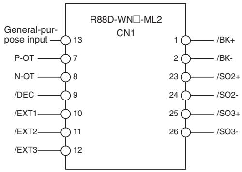
I/O Signal Allocations (Default Settings)
Required Parameter Settings
The following servo parameters are used to control the MC Unit. Make sure that they are set correctly and do not change them.
List
| Parameter No. | Parameter |
| Pn800.0 | Communications control, MECHATROLINK-II communications check mask |
| Pn800.1 | Communications control, warning check mask |
| Pn801.0 | Software limit function |
| Pn801.2 | Software limit Check Using Reference |
| Pn824 | Option monitor 1 selection |
| Pn825 | Option monitor 2 selection |
| Pn008.2 | Function selection application switches 8, warning detection selection |
| Pn20E | Electronic gear ratio G1 (numerator) |
| Pn210 | Electronic gear ratio G2 (denominator) |
Individual Descriptions
Pn800.0 Communications Control, MECHATROLINK Communications Check Mask
| Parameter No. | Parameter name | Unit | Fixed setting | Settings | Default settings | Required settings |
| Pn800.0 | Communications control MECHATROLINK-II communica-tions check mask | --- | 0 | 0: Detects communica-tions error (A.E60) and WDT error (A.E50) | 0 | 0 |
Make sure that MECHATROLINK communications errors, such as A.E60 (communications error) and A.E50 (WDT error (synchronization error)), can be detected. The MC Unit uses them when controlling communications.
Use the default setting of 0 (communications error (A.E60) and WDT error (A.E50)) for Pn800.0.
Pn800.1 Communications Control Warning Check Mask
| Parameter No. | Parameter name | Unit | Fixed setting | Settings | Default settings | Required settings |
| Pn800.1 | Communications control, warning check mask | --- | 4 or 0 | 4: Ignore communications warnings (A.96☐)0: Detect A.94☐, A.95☐, and A.96☐. | 4 | 0 |
Make sure that MECHATROLINK communications warnings, such as A.94 (data setting alarm) and A.95 (command alarm), are not ignored. The MC Unit uses them when controlling communications.
Set Pn800.1 to the default setting of 4 (ignore communications alarm (A.96□) only or to 0 (detect A.94□, A.95□, and A.96□).
Pn801.0 Software Limits
| Parameter No. | Parameter name | Unit | Setting range | Settings | Default settings | Required settings |
| Pn801.0 | Software limits | --- | 0 to 3 | 0: Enables software limit1: Enables forward soft-ware limit2: Enables reserve soft-ware limit3: Enables both software limits | 3 | 3 |
Leave the software limit function set on the default setting of 3.
Pn801.2 Software Limit Check Using Reference
| Parameter No. | Parameter name | Unit | Setting range | Settings | Default settings | Required settings |
| Pn801.2 | Software limit check using reference | --- | 0 to 1 | 0: No software limit check using reference1: Software limit check using reference | 0 | 0 |
Leave the software limit check set to the default setting of 0.
Pn824/Pn825 Option Monitor
| Parameter No. | Parameter name | Unit | Setting range | Settings | Default settings | Required settings |
| Pn824 | Option monitor 1 selection | --- | 0000 to 0024 Hex | Specifies monitor information. | 0000 Hex | 0023 Hex |
| Pn825 | Option monitor 2 selection | --- | 0000 to 0024 Hex | Specifies monitor information. | 0000 Hex | 0024 Hex |
Set the option monitor 1 selection to 0023 Hex and the option monitor 2 selection to 0024 Hex.
Pn008.2 Function Selection Application Switches 8, Warning Detection Selection
| Parameter No. | Parameter name | Unit | Fixed setting | Settings | Default settings | Required settings |
| Pn008.2 | Function Selection Application Switches 8, Warning Detection Selection | --- | 1 | 0: Detects warnings1: Does not detect warnings | 0 | 0 |
Leave the default setting of 0.
Setting Pn008.2 to 1 (Do not detect warning) will prevent detection of the following alarms.
A.900 (Excessive position deviation warning)
A.901 (Excessive position deviation for Servo ON)
A.910 (Overload)
A.911 (Vibration)
A.920 (Regenerative overload)
A.930 (Absolute encoder battery error)
Pn20E/Pn210 Electronic Gear Settings
| Parameter No. | Parameter name | Unit | Setting range | Settings | Default settings | Required settings |
| Pn20E | Electronic gear ratio G1 (numera-tor) | --- | 1 to 1,073,74 1,824 | Electronic gear numerator | 1 | 1 |
| Pn210 | Electronic gear ratio G2 (denomi-nator) | --- | 1 to 1,073,74 1,824 | Electronic gear denomina-tor | 1 | 1 |
Leave the electronic gear settings set to the default setting of 1 (1/1).
Revision History
A manual revision code appears as a suffix to the catalog number on the front cover of the manual.
Cat. No. W435-E1-05
Revision code
The following table outlines the changes made to the manual during each revision. Page numbers refer to the previous version.
| Revision code | Date | Revised content |
| 01 | September 2004 | Original production |
| 02 | June 2005 | Page v: Wording of DANGER and WARNING definitions changed.Page vii: Confirming Unit Versions with Support Software replaced and expanded.Page xiv: Material added.Page 4: "Always" added to note 5.Page 5: Product name corrected to "Terminator" and Specification Overview for Termina-tor changed.Page 18: Performance table replaced.Page 20, 21, 59: Material added, deleted, or moved to appendix.Page 33: Last part of bottom note separated into body text.Page 54: Item added under P00004.Page 57: P3AA08 changed to "reserved."Page 60: Description of bit 02 changed and description of bit 08 added.Page 61: Addition made to description of bit 00 at top of page.Page 65: "MC Unit has started up" changed.Page 71: Description of setting 00000000 Hex (0) changed and "00 to 03 bit" removed at two places.Page 72: "Present position" changed at three places.Page 79: Description of P3AA08 changed.Page 90: Formulas for Precision of feedback speed 2 changed.Page 96: Changes made for SW0000, SW000C, SW0010, and SW0011.Page 108: Material deleted from SW0200 and SW0202 and added for SW020C/Page 109: Material added for SW0210 and deleted from SW0214.Page 145: Classification changed to "reserved" in top tablePages 157 and 158: Names and specifications changed to "reserved."Page 172: Middle table changed.Page 174, 176, 177, and 180 to 183: Shading changed.Page 178: "Same as above" removed for Pn50B.Page 184 and 185: Notes removed.Page 216: List changed to notes and "20 seconds" changed to "30 seconds."Page 255: Row added toward bottom of table.Page 281: ".00" deleted before table and "ms" added in table.Page 299: Underbars added in middle of page and "%" changed to "r/min" in note 1.Pages 301 and 302: Spaces added in Program Image and underbars added in command format.Page 303: Spaces added in Program Image.Page 311: Reference in note changed.Page 341: Table at top of page changed.Page 341 and 342: Customer I/O Area Allocation changed.Page 368 and 518: Addition made at top of page.Page 412, 417: Space added in program.Page 472: Additions made in first bulleted paragraph in Status Conditions.Page 484: Description of function changed.Page 485: Item added to Effect on Other Functions.Page 522: Addition made in graphic text.Page 536 and 537: 10-1-11 Positioning with Circular.... deleted.Page 580: First sentence in 11-1-1 Items to Check First changed.Page 587: Addition made to details of MLK Device alarm in top table.Page 603: Addition made at bottom of page.Page 604: Row deleted at top of page.Pages 605 and 606: Section replaced.Page 614: Appendix added. |
| 03 | October 2006 | Pages viii to xii: Information added on unit versions.Page 3: Information added on features.Page 5: Information added on Peripheral Devices.Page 10: Information added on data tracing.Page 11: Information added on zone function.Page 14 and 15: Information added on performance specifications.Page 19: Information added on commands.Page 20: Information added on MC Unit processing.Page 24 and 25: Information added on CX-Motion-MCH.Page 49 to 57: Information added on system parameters.Page 60, 61, 68 to 70, 94, and 95: Information added on zone parameters.Page 107: Information added on system variables.Page 109: Information added on motion tasks.Page 115: Information added on data tracing variables.Page 153: Information added on zone control bits.Page 158: Information added on zone reservation bits/Page 175: Information added on zone monitoring status bits/Page 182 Information added on present position preset/Page 198: Information added on position loop gain index/Page 218: Information added on saving data.Pages 222 to 223: Information added on motion program.Page 529: Information added on breakpoints.Page 541: Information added on trace functionPages 542 to 544: Information added on zone function. |
| 04 | July 2007 | Changes and additions accompanying the upgrade to unit version 3.1 and corresponding changes for upgrading the CX-Motion-MCH Support Software.Corrections to previous material. |
| 05 | June 2008 | Page x: Changed data and lot number in bottom table.Page 60: Removed fourth bulleted paragraph at top of page.Page 195: Change initial setting for bit 0 of mode switch select parameter.Page 204: Changed setting for 9003.Page 259 and 260: Replaced table.Page 594: Changed to "position 500" in second bulleted paragraph and item 7 at bottom of page.Page 596: Changed to "position 500" in item 7.Page 598: Changed "slave" to "master in item 3/4 in middle of page. |