
RC 5500SR - Universal remote MARANTZ - Free user manual and instructions
Find the device manual for free RC 5500SR MARANTZ in PDF.


| Product type | Universal remote control |
| Brand | Marantz |
| Model | RC 5500SR |
| Dimensions (approx.) | 20 cm x 6 cm x 3 cm |
| Weight (approx.) | 200 g (with batteries) |
| Power supply | 2 AAA batteries (not included) |
| Main functions | Control multiple devices (amplifier, TV, DVD player, etc.), IR code learning, input selection, volume adjustment, surround modes |
| Number of controllable sources | Up to 8 sources (CD, TV, TAPE, DVD, CD-R, VCR1, DSS, COMP1, COMP2) |
| Display | FL display (Fluorescent Display) with backlight |
| Infrared range | Approximately 10 meters |
| Care and cleaning | Use a soft, dry cloth. Do not use abrasive products or solvents. |
| Safety precautions | Do not expose to moisture, extreme temperatures, or direct sunlight. Remove batteries if the device is not used for an extended period. |
| Spare parts and repairability | Batteries are user-replaceable. For any other parts, contact an authorized Marantz service center. |
| General information | This Class B digital apparatus complies with Canadian ICES-003. Manual available for free download in PDF format. |
Frequently Asked Questions - RC 5500SR MARANTZ
User questions about RC 5500SR MARANTZ
0 question about this device. Answer the ones you know or ask your own.
Ask a new question about this device
Download the instructions for your Universal remote in PDF format for free! Find your manual RC 5500SR - MARANTZ and take your electronic device back in hand. On this page are published all the documents necessary for the use of your device. RC 5500SR by MARANTZ.
USER MANUAL RC 5500SR MARANTZ
AV Surround Receiver
CAUTION
RISK OF ELECTRIC SHOCK DO NOT OPEN

CAUTION: TO REDUCE THE RISK OF ELECTRIC SHOCK,
DO NOT REMOVE COVER (OR BACK)
NO USER-SERVICEABLE PARTS INSIDE
REFER SERVICING TO QUALIFIED SERVICE PERSONNEL
The lightning flash with arrowhead symbol within an equilateral triangle is intended to alert the user to the presence of uninsulated "dangerous voltage" within the product's enclosure that may be of sufficient magnitude to constitute a risk of electric shock to persons.

The exclamation point within an equilateral triangle is intended to alert the user to the presence of important operating and maintenance (servicing) instructions in the literature accompanying the product.
WARNING
TO REDUCE THE RISK OF FIRE OR ELECTRIC SHOCK,
DO NOT EXPOSE THIS PRODUCT TO RAIN OR MOISTURE.
CAUTION: TO PREVENT ELECTRIC SHOCK, MATCH WIDE BLADE OF PLUG TO WIDE SLOT, FULLY INSERT.
ATTENTION: POUR ÉVITER LES CHOC ÉLECTRIQUES, INTRODUIRE LA LAME LA PLUS LARGE DE LA FICHE DANS LA BORNE CORRESPONDANTE DE LA PRISE ET POUSSER JUSQU'AU FOND.
NOTE TO CATV SYSTEM INSTALLER:
This reminder is provided to call the CATV (Cable-TV) system installer's attention to Section 820-40 of the NEC which provides guidelines for proper grounding and, in particular, specifies that the cable ground shall be connected to the grounding system of the building, as close to the point of cable entry as practical.
NOTE:
This equipment has been tested and found to comply with the limits for a Class B digital device, pursuant to Part 15 of the FCC Rules. These limits are designed to provide reasonable protection against harmful interference in a residential installation. This equipment generates, uses and can radiate radio frequency energy and, if not installed and used in accordance with the instructions, may cause harmful interference to radio communications. However, there is no guarantee that interference will not occur in a particular installation. If this equipment does cause harmful interference to radio or television reception, which can be determined by tuning the
equipment off and on, the user is encouraged to try to correct the interference by one or more of the following measures:
- Reorient or relocate the receiving antenna.
- Increase the separation between the equipment and receiver.
- Connect the equipment into an outlet on a circuit different from that to which the receiver is connected.
- Consult the dealer or an experienced radio/TV technician for help.
IMPORTANT SAFETY INSTRUCTIONS
READ BEFORE OPERATING EQUIPMENT
This product was designed and manufactured to meet strict quality and safety standards. There are, however, some installation and operation precautions which you should be particularly aware of.
- Read Instructions - All the safety and operating instructions should be read before the product is operated.
- Retain Instructions - The safety and operating instructions should be retained for future reference.
- HeedWarnings - All warnings on the product and in the operating instructions should be adhered to.
- Follow Instructions - All operating and use instructions should be followed.
- Cleaning - Unplug this product from the wall outlet before cleaning. Do not use liquid cleaners or aerosol cleaners. Use a damp cloth for cleaning.
- Attachments - Do not use attachments not recommended by the product manufacturer as they may cause hazards.
- Water and Moisture - Do not use this product near water-for example, near a bath tub, wash bowl, kitchen sink, or laundry tub, in a wet basement, or near a swimming pool, and the like.
-
Accessories - Do not place this product on an unstable cart, stand, tripod, bracket, or table. The product may fall, causing serious injury to a child or adult, and serious damage to the product. Use only with a cart, stand, tripod, bracket, or table recommended by the manufacturer, or sold with the product. Any mounting of the product should follow the manufacturer's instructions, and should use a mounting accessory recommended by the manufacturer.
-
A product and cart combination should be moved with care. Quick stops, excessive force, and uneven surfaces may cause the product and cart combination to overturn.

- Ventilation - Slots and openings in the cabinet are provided for ventilation and to ensure reliable operation of the product and to protect it from overheating, and these openings must not be blocked or covered. The openings should never be blocked by placing the product on a bed, sofa, rug, or other similar surface. This product should not be placed in a built-in installation such as a bookcase or rack unless proper ventilation is provided or the manufacturer's instructions have been adhered to.
-
Power Sources - This product should be operated only from the type of power source indicated on the marking label. If you are not sure of the type of power supply to your home, consult your product dealer or local power company. For products intended to operate from battery power, or other sources, refer to the operating instructions.
-
Grounding or Polarization - This product may be equipped with a polarized alternating-current line plug (a plug having one blade wider than the other). This plug will fit into the power outlet only one way. This is a safety feature. If you are unable to insert the plug fully into the outlet, try reversing the plug. If the plug should still fail to fit, contact your electrician to replace your obsolete outlet. Do not defeat the safety purpose of the polarized plug.
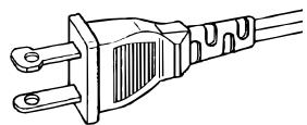
AC POLARIZED PLUG
- Power-Cord Protection - Power-supply cords should be routed so that they are not likely to be walked on or pinched by items placed upon or against them, paying particular attention to cords at plugs, convenience receptacles, and the point where they exit from the product.
- Protective Attachment Plug - The product is equipped with an attachment plug having overload protection. This is a safety feature. See Instruction Manual for replacement or resetting of protective device. If replacement of the plug is required, be sure the service technician has used a replacement plug specified by the manufacturer that has the same overload protection as the original plug.
-
Outdoor Antenna Grounding - If an outside antenna or cable system is connected to the product, be sure the antenna or cable system is grounded so as to provide some protection against voltage surges and built-up static charges. Article 810 of the National Electrical Code, ANSI/NFPA 70, provides information with regard to proper grounding of the mast and supporting structure, grounding of the lead-in wire to an antenna discharge unit, size of grounding conductors, location of antenna-discharge unit, connection to grounding electrodes, and requirements for the grounding electrode. See Figure 1.
-
Lightning - For added protection for this product during a lightning storm, or when it is left unattended and unused for long periods of time, unplug it from the wall outlet and disconnect the antenna or cable system. This will prevent damage to the product due to lightning and power-line surges.
- Power Lines - An outside antenna system should not be located in the vicinity of overhead power lines or other electric light or power circuits, or where it can fall into such power lines or circuits. When installing an outside antenna system, extreme care should be taken to keep from touching such power lines or circuits as contact with them might be fatal.
- Overloading - Do not overload wall outlets, extension cords, or integral convenience receptacles as this can result in a risk of fire or electric shock.
- Object and Liquid Entry – Never push objects of any kind into this product through openings as they may touch dangerous voltage points or short-out parts that could result in a fire or electric shock. Never spill liquid of any kind on the product.
- Servicing - Do not attempt to service this product yourself as opening or removing covers may expose you to dangerous voltage or other hazards. Refer all servicing to qualified service personnel.
- Damage Requiring Service - Unplug this product from the wall outlet and refer servicing to qualified service personnel under the following conditions:
a. When the power-supply cord or plug is damaged.
b. If liquid has been spilled, or objects have fallen into the product.
c. If the product has been exposed to rain or water.
d. If the product does not operate normally by following the operating instructions. Adjust only those controls that are covered by the operating instructions as an improper adjustment of other controls may result in damage and will often require extensive work by a qualified technician to restore the product to its normal operation.
e. If the product has been dropped or damaged in any way, and
f. When the product exhibits a distinct change in performance - this indicates a need for service.
- Replacement Parts - When replacement parts are required, be sure the service technician has used replacement parts specified by the manufacturer or have the same characteristics as the original part. Unauthorized substitutions may result in fire, electric shock, or other hazards.
- Safety Check - Upon completion of any service or repairs to this product, ask the service technician to perform safety checks to determine that the product is in proper operating condition.
- Wall or Ceiling Mounting - The product should be mounted to a wall or ceiling only as recommended by the manufacturer.
- Heat - The product should be situated away from heat sources such as radiators, heat registers, stoves, or other products (including amplifiers) that produce heat.
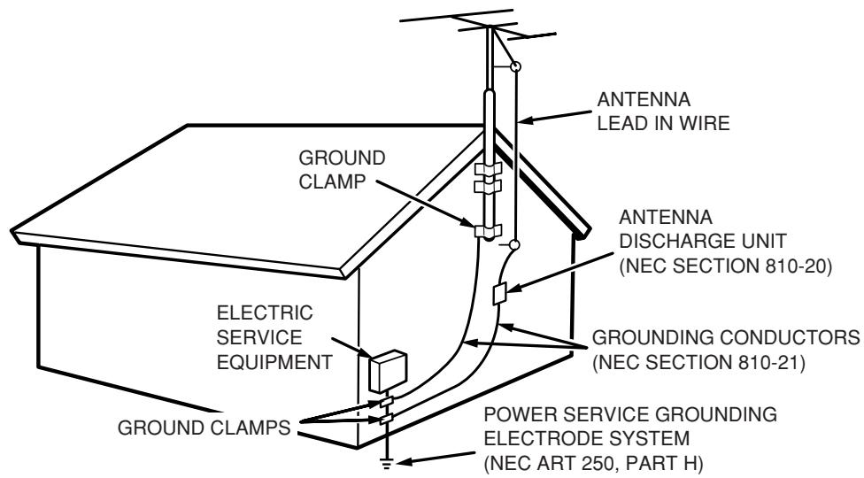
FIGURE 1 EXAMPLE OF ANTENNA GROUNDING AS PER NATIONAL ELECTRICAL CODE, ANSI/NFPA 70
NEC - NATIONAL ELECTRICAL CODE
This Class B digital apparatus complies with Canadian ICES-003.
Thank you for purchasing the Marantz SR5500 Surround receiver.
This remarkable component has been engineered to provide you with many years of home theater enjoyment. Please take a few minutes to read this manual thoroughly before you connect and operate the SR5500.
As there are a number of connection and configuration options, you are encouraged to discuss your own particular home theater setup with your Marantz A/V specialist dealer.
PRECAUTIONS
CAUTIONS ON INSTALLATION
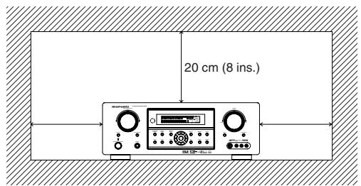
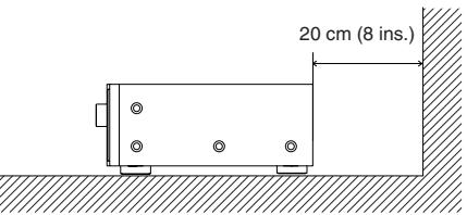
For heat dispersal, leave at least 20 cm/8 inch of space between the top, back and sides of this unit and the wall or other components.
- Do not obstruct the ventilation holes.
HSITONE
DESCRIPTION
DIGITAL

SURROUND
- DTS was introduced in 1994 to provide 5.1 channels of discrete digital audio into home theater systems.
- DTS brings you premium quality discrete multichannel digital sound to both movies and music.
- DTS is a multichannel sound system designed to create full range digital sound reproduction.
The no compromise DTS digital process sets the standard of quality for cinema sound by delivering an exact copy of the studio master recordings to neighborhood and home theaters.
Now, every moviegoer can hear the sound exactly as the moviemaker intended.
DTS can be enjoyed in the home for either movies or music on of DVD's, LD's, and CD's.
"DTS" and "DTS Digital Surround" are registered trademarks of Digital Theater Systems, Inc.

The advantages of discrete multichannel systems over matrix are well known.
But even in homes equipped for discrete multichannel, there remains a need for high-quality matrix decoding. This is because of the large library of matrix surround motion pictures available on disc and on VHS tape; and analog television broadcasts. The typical matrix decoder of today derives a center channel and a mono surround channel from two-channel matrix stereo material. It is better than a simple matrix in that it includes steering logic to improve separation, but because of its mono, band-limited surround it can be disappointing to users accustomed to discrete multichannel.
Neo:6 offers several important improvements as follow,
- Neo:6 provides up to six full-band channels of matrix decoding from stereo matrix material. Users with 6.1 and 5.1 systems will derive six and five separate channels, respectively, corresponding to the standard home-theater speaker layouts.
- Neo:6 technology allows various sound elements within a channel or channels to be steered separately, and in a way which follows naturally from the original presentation.
- Neo:6 offers a music mode to expand stereo nonmatrix recordings into the five- or six-channel layout, in a way which does not diminish the subtlety and integrity of the original stereo recording.
EXTENDED

SURROUN
DTS-ES Extended Surround is a new multichannel digital signal format developed by Digital Theater Systems Inc. While offering high compatibility with the conventional DTS Digital Surround format, DTS-ES Extended Surround greatly improves the 360-degree surround impression and space expression thanks to further expanded surround signals. This format has been used professionally in movie theaters since 1999.
In addition to the 5.1 surround channels (FL, FR, C, SL, SR and LFE), DTS-ES Extended Surround also offers the SB (Surround Back) channel for surround playback with a total of 6.1 channels. DTS-ES Extended Surround includes two signal formats with different surround signal recording methods, as DTS-ES Discrete 6.1 and DTS-ES Matrix 6.1.
"DTS", "DTS-ES" and "Neo:6" are trademarks of Digital Theater Systems, Inc.
The stereo CD is a 16-bit medium with sampling at 44.1kHz . Professional audio has been 20- or 24-bit for some time, and there is increasing interest in higher sampling rates both for recording and for delivery into the home. Greater bit depths provide extended dynamic range. Higher sampling rates allow wider frequency response and the use of anti-alias and reconstruction filters with more favorable aural characteristics.
DTS 96/24 allows for 5.1 channel sound tracks to be encoded at a rate of 96kHz / 24 bits on DVD-Video titles.
When DVD-video appeared, it became possible to deliver 24-bit, 96kHz audio into the home, but only in two channels, and with serious limitations on picture. This capability has had little use.
DVD-audio allows 96/24 in six channels, but a new player is needed, and only analog outputs are provided, necessitating the use of the D/A converters and analog electronics provided in the player.
DTS 96/24 offers the following:
- Sound quality transparent to the original 96/24 master.
-
Full backward compatibility with all existing decoders. (Existing decoders will output a 48 kHz signal)
-
No new player required: DTS 96/24 can be carried on DVD-video, or in the video zone of DVD-audio, accessible to all DVD players.
4.96/24 5.1-channel sound with full-quality full-motion video, for music programs and motion picture soundtracks on DVD-video.
"DTS" and "DTS 96/24" are trademarks of Digital Theater Systems, Inc.

Dolby Digital identifies the use of Dolby Digital audio coding for such consumer formats as DVD and DTV. As with film sound, Dolby Digital can provide up to five full-range channels for left, center, and right screen channels, independent left and right surround channels, and a sixth (".1") channel for low-frequency effects.
Dolby Surround Pro Logic II is an improved matrix decoding technology that provides better spatiality and directionality on Dolby Surround program material; provides a convincing three-dimensional soundfield on conventional stereo music recordings; and is ideally suited to bring the surround experience to automotive sound. While conventional surround programming is fully compatible with Dolby Surround Pro Logic II decoders, soundtracks will be able to be encoded specifically to take full advantage of Pro Logic II playback, including separate left and right surround channels. (Such material is also compatible with conventional Pro Logic decoders.)
Dolby Digital EX creates six full-bandwidth output channels from 5.1-channel sources. This is done using a matrix decoder that derives three surround channels from the two in the original recording. For best results, Dolby Digital EX should be used with movies soundtracks recorded with Dolby Digital Surround EX.
About Dolby Pro Logic IIx
Dolby Pro Logic IIx technology delivers a natural and immersive 7.1-channel listening experience to the home theater environment. A product of Dolby's expertise in surround sound and matrix decoding technologies, Dolby Pro Logic IIx is a complete surround sound solution that maximizes the entertainment experience from stereo as well as 5.1-channel encoded sources.
Dolby Pro Logic IIx is fully compatible with Dolby Surround Pro Logic technology and can optimally decode the thousands of commercially available Dolby Surround encoded video cassettes and television programs with enhanced depth and spatiality. It can also process any high-quality stereo or Advanced Resolution 5.1-channel music content into a seamless 6.1- or 7.1-channel listening experience.
The Dolby Headphone technology provides a surround sound listening experience over headphones. When listening to multichannel content such as DVD movies over headphones, the listening experience is fundamentally different than listening to speakers. Since the headphone speaker drivers are covering the pinna of the ear, the listening experience differs greatly from traditional speaker playback. Dolby utilizes patented headphone perspective curves to solve this problem and provides a non-fatiguing, immersive, home theater listening experience. Dolby Headphone also delivers exceptional 3D audio from stereo material.
Manufactured under license from Dolby Laboratories. "Dolby", "Pro Logic", and the double-D symbol are trademarks of Dolby Laboratories.

Circle Surround II (CS-II) is a powerful and versatile multichannel technology. CS-II is designed to enable up to 6.1 multichannel surround sound playback from mono, stereo, CS encoded sources and other matrix encoded sources. In all cases the decoder extends it into 6 channels of surround audio and a LFE/subwoofer signal. The CS-II decoder creates a listening environment that places the listener "inside" music performances and dramatically improves both hi-fi audio conventional surround-encoded video material. CS-II provides composite stereo rear channels to greatly improve separation and image positioning - adding a heightened sense of realism to both audio and A/V productions.
CS-II is packed with other useful feature like dialog clarity (SRS Dialog) for movies and cinema-like bass enrichment (TruBass). CS-II can enable the dialog to become clearer and more discernable in movies and it enables the bass frequencies contained in the original programming to more closely achieve low frequencies – overcoming the low frequency limitations of the speakers by full octave.
Circle Surround II, Dialog Clarity, TruBass, SRS and () symbol are trademarks of SRS Labs, Inc.
Circle Surround II, Dialog Clarity and TruBass technology are incorporated under license from SRS Labs, Inc.
FEATURES
The SR5500 incorporates the latest generation of digital surround sound decoding technology such as Dolby Digital EX, Dolby Digital, DTS-ES (Discrete 6.1 and Matrix 6.1), DTS Neo:6 (Cinema, Music), Dolby Pro-Logic IIx (Movie, Music and Game), Circle Surround II (Cinema and Music). In addition, Marantz has focused on the future. By utilizing pre-out jacks, 7.1 direct inputs and a RS232C communication port, the SR5500 is tomorrow's technology, today!
The SR5500 features a fully discrete 7 channel amplifier section capable of delivering 90 watts of high-current amplification, for continuously clean and stable power into each of the 7 channels. It employs a massive EI power transformer in combination with oversized filter capacitors. Current feedback topology allows total operation stability, while requiring minimal amounts of negative feed-back, resulting in an excellent transient frequency response and superb sonic transparency. This design configuration is capable of a clear and powerful reproduction of the most demanding action movie soundtracks and full range (multichannel) music discs. Through its ability to generate very high output voltages, the SR5500 can easily drive the most demanding speakers with optimum results.
The SR5500 incorporates the most advanced Digital Signal Processing circuitry, along with a Crystal 192kHz / 24 bit D/A converter in each of the 8 channels. Independent power supply circuits are incorporated for the FL display, audio and video sections for maximum separation, clarity and dynamic range. Together with hand-selected customized components, all elements work in harmony to recreate the emotion, exactly as the artist had intended.
The SR5500 is designed and engineered with extensive feedback from custom installation experts, dealers and consumers. It features multi-room/multisource, a RS-232C communication port, heavy duty speaker binding posts and an extensive array of both analog and digital inputs / outputs. With 4 assignable digital inputs, 2 assingnable component inputs, SACD Multi Channel (7.1 channel) direct inputs video convert system and OSD output versatility is taken to a stunning new level. Furthermore, the SR5500 can output the OSD information through the Y/C (S-video) and composite video outputs.
An easy-to-use universal remote control allows full access to all of the operating functions and can be used for system operation as well.
This unit has Simple Setup function for easy setup. You can setup all speaker settings by just selecting your room size and the number of your speakers with Simple Setup function. You can also setup customized settings just like conventional AV amplifiers.
- Dolby Digital EX, Dolby Digital ,
DTS ES (Discrete 6.1, Matrix 6.1, Neo: 6) - Dolby Headphone (DH1, DH2, DH3)
- Dolby Pro Logic IIx (Movie, Music, Game)
Circle Surround II (Movie, Music, Mono) - 7 × 90 Watts (8 Ohm), Discrete Amplifiers
High Power Current Feedback Circuitry - Massive Energy Power Supply, Huge El Transformer, Large ELCO's.
192 kHz/24 bit Crystal® DAC for all 8 Channels
32 bit Digital Surround Processing Chipsets
Video Off Mode
Large Heavy Duty Speaker Terminals for all Channels - RS-232C Terminal for System Control
- Set Up Menu via all Video Output (Composite, S-Video and Component video)
- Auto Input Signal Detection
- Improved Station Name Input Method, 50 Presets
- Auto Adjust Function for Speaker Distance Settings (Delay Time)
- Front AUX Input (Digital Camera, Portable DVD)
- Universal remote control
- Simple Setup Function
Video convert system - LIP.SYNC Funciton (Audio delay)
ACCESSORIES
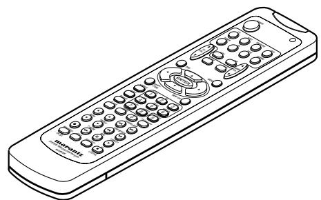
Remote Controller RC5500SR
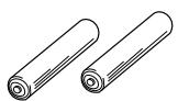
AAA-size batteries X 2
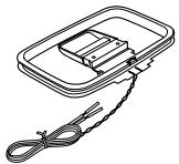
AM Loop Antenna
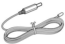
FM Antenna
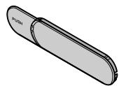
Front AUX Jack Cover
User Guide
FRONT PANEL
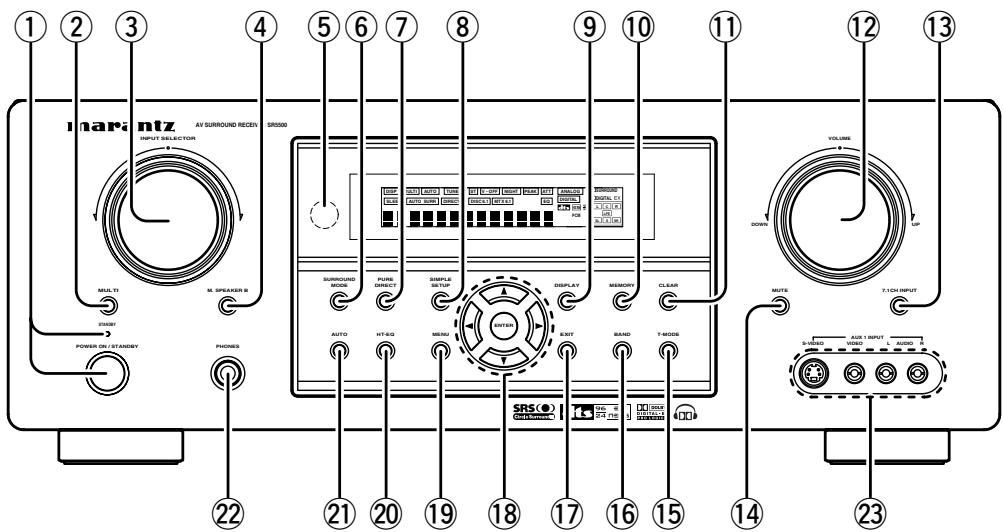
① POWER switch and STANDBY indicator
When this switch is pressed once, the unit turns ON and the display illuminates. When pressed again, the unit turns OFF and the STANDBY indicator will be illuminated.
② MULTI (Multi Room) button
Press this button to activate the Multiroom system. "MULTI" indicator will be illuminated in the display.
③ INPUT SELECTOR knob (AUDIO/VIDEO)
This knob is used to select the input sources. The video function selector, such as TV, DVD, VCR1 and DSS, selects video and audio simultaneously. Audio function sources such as CD, TAPE, CDR/ MD, and TUNER may be selected in conjunction with a Video source.
This feature (Sound Injection) combines a sound from one source with a picture from another.
Choose the video source first, and then choose a different audio source to activate this function.
M.(Multi Room) SPEAKER B button
Press this button to activate the Multiroom Speaker B system. "MULTI" indicator will be illuminated in the display. (See page 32)
⑤ INFRARED receiving sensor window
This window receives infrared signals for the remote control.
⑥ SURROUND MODE button
You can select the surround mode by pressing this button.
⑦ PURE DIRECT button
When this button is pressed, the tone control circuitry is bypassed as well as Bass Management. "DIRECT" indicator will be illuminated in the display.
Notes:
- The surround mode is automatically switched to AUTO when the pure direct function is turned on.
- Additionally, Speaker Configurations are fixed automatically as follows.
- Front SPKR = Large, Center SPKR = Large,
- Surround SPKR = Large, Subwoofer = On
- This function is unavailable when the M. speaker B system is activated. While this function is activated, this function will be canceled if the M. SPEAKER B button is pressed.
(8) SIMPLE SETUP button
Press this button to enter the simple setup mode. You can setup the speaker conditions (speaker sizes, number of speakers, speaker delay times) quickly by pressing the cursor buttons.
⑨ DISPLAY button
When this button is pressed, the FL display mode is changed as Surround Mode Auto-display Off Display Off Input Function and the display off indicator(DISP) lights up in condition of DISPLAY OFF.
10 MEMORY button
Press this button to enter the tuner preset memory numbers or station names. (See page 30)
11 CLEAR button
Press this button to cancel the station-memory setting mode or preset scan tuning. (See page 30)
12 VOLUME control knob
Adjusts the overall sound level. Turning the control clockwise increases the sound level.
13 7.1CH INPUT button
Press this button to select the output of an external multichannel player.
14 MUTE button
Press this button to mute the output to the speakers. Press it again to return to the previous volume level.
15 T-MODE button
Press this button to select the auto stereo mode or mono mode when the FM band is selected. The "AUTO" indicator lights in the auto stereo mode. (See page 30)
16 BAND button
Press this button to switch between FM and AM in the TUNER mode.
17 EXIT button
This button is used to exit from the SETUP MAIN MENU.
18 Cursor ( , , ,) /ENTER button
Use these buttons when operating the SETUP MAIN MENU and TUNER function.
19 MENU button
This button is used to enter the SETUP MAIN MANU.
20 HT-EQ button
Used to turn on or off HT(Home Theater)-EQ mode. This mode compensates for the audio portion of a movie sounding "bright". When this button is pressed, "EQ" indicator lights up.
21 AUTO (Auto surround) button
Press this button to select the AUTO mode from the surround modes. When this mode is selected, the receiver determines the surround mode corresponding to a digital input signal automatically.
22 HEADPHONE jack for stereo headphones
This jack may be used to listen to the SR5500's output through a pair of headphones. Be certain that the headphones have a standard 1/4" stereophone plug. Note that the main room speakers will automatically be turned off when the headphone jack is in use.
Notes:
- When using headphones, the surround mode will change to STEREO and Dolby Headphone by MENU and Cursor button.
- The surround mode returns to the previous setting as soon as the headphone plug is removed from the jack.
23 AUX1 INPUT jacks
These auxiliary video.audio input jacks accept the connections of a camcorder, portable DVD, game etc.
FL DISPLAY
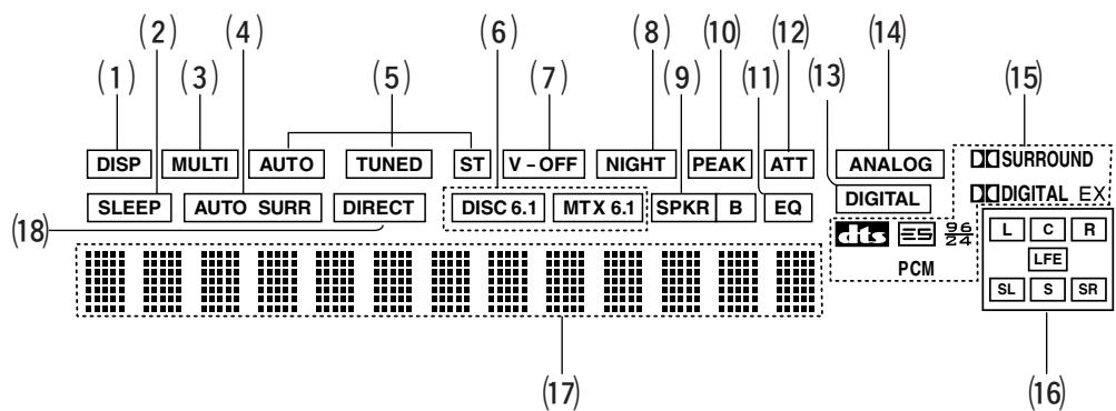
(1) DISP(Display Off) indicator
This indicator is illuminated when the SR5500 is in the display off condition.
(2) SLEEP timer indicator
This indicator is illuminated when the sleep timer function in the main-room is in use.
(3) Multi-room system indicator
This indicator is illuminated when the multi-room system is active.
(4) AUTO SURR (Auto Surround mode) indicator
This indicator is illuminated to show that the AUTO SURROUND mode is in use.
(5) TUNER's indicators
AUTO : This indicator illuminates when the tuner's Auto mode is in use.
TUNED: This indicator illuminates when a station is being received with sufficient signal strength to provide acceptable listening quality.
ST(Stereo): This indicator illuminates when an FM station is being tuned into stereo condition.
(6) DTS-ES mode indicators (DISC6.1, MTX6.1)
These indicators will illuminate to show the DTS-ES decoding mode (Discrete 6.1 or Matrix 6.1).
(7) V(video)-OFF mode indicator
This indicator is illuminated when the Video-OFF function is active.
(8) NIGHT mode indicator
This indicator is illuminated when the SR5500 is in the Night mode, which reduces the dynamic range of digital program material at low volume levels.
(9) SPKR (speaker) B indicator
This indicator is illuminated when the M (Multiroom) speaker B system is active.
(10) PEAK indicator
This indicator is a monitor for an analog audio input signal. If the selected analog audio input signal is greater than the capable level of internal processing, this will illuminate. If this happens, you should press the ATT button on the remote.
(11) EQ mode indicator
This indicator is illuminated when the HT-EQ function is active.
(12) ATT (Attenuation) indicator
This indicator is illuminated when the attenuation function is active.
(13) DIGITAL Input Indicator
This indicator lights when a digital input has been selected.
(14) ANALOG input indicator
This indicator is illuminated when an analog input source has been selected.
(15) SIGNAL FORMAT indicators
DIGITAL, EX, SURROUND, dts, ES, 96/24, PCM
When the selected input is a digital source, some of these indicators will be illuminated to display the specific type of signal in use.
(16) ENCODED CHANNEL STATUS indicators
These indicators display the channels that are encoded with a digital input signal. If the selected digital input signal is Dolby Digital 5.1ch or DTS 5.1ch, "L", "C", "R", "SL", "SR" and "LFE" will be illuminated. If the digital input signal is 2 channel PCM-audio, "L" and "R" will be displayed.
If Dolby Digital 5.1ch signal with Surround EX flag or DTS-ES signal comes in, "L", "C", "R", "SL", "S", "SR" and "LFE" will be illuminated.
(17) Main Information Display
This display shows messages relating to the status, input source, surround mode, tuner, volume level or other aspects of unit's operation.
(18) DIRECT (Puredirect) indicator
This indicator is illuminated when the SR5500 is in the PURE DIRECT mode.
HOW TO ATTACH THE FRONT AUX JACK COVER
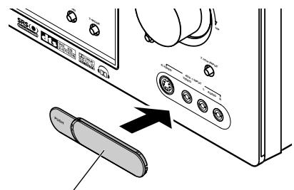
Front AUX Jack Cover
REAR PANEL
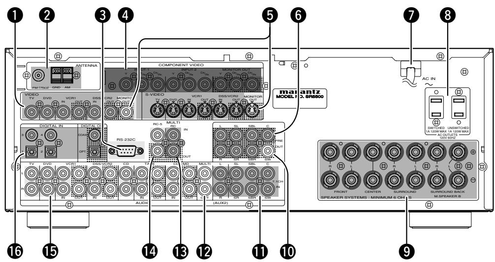
VIDEO IN/OUT (TV, DVD, VCR1, DSS/VCR2)
These are the video inputs and outputs. There are 4 video inputs and 2 video outputs and each one includes both composite video and S-video configurations. Connect VCRs, DVD players, and other video components to the video inputs.
The 2 video output channels can be used to be connected to video tape recorders for making recordings.
The input signals of video and S-video are converted each other, and each of the converted video signals can be output.
FM antenna terminal (75 ohms)
Connect an external FM antenna with a coaxial cable, or a cable network FM source.
AM antenna and ground terminals
Connect the supplied AM loop antenna. Use the terminals marked "AM" and "GND". The supplied AM loop antenna will provide good AM reception in most areas. Position the loop antenna until you hear the best reception.
RS-232C
The RS-232C port is to be used in conjunction with an external controller to control the operation of the SR5500 by using an external device.
COMPONENTVIDEOINPUT/OUTPUT
If your DVD player or other device has component video connectors, be sure to connect them to these component video connectors on the SR5500. The SR5500 has two component video input connectors to obtain the color information (Y, C_B , C_R ) directly from the recorded DVD signal or other video component and one component video output connector to output it directly into the matrix decoder of the display device.
By sending the pure DVD component video signal directly, the DVD signal forgoes the extra processing that normally would degrade the image. The result is vastly increased image quality, with incredibly life like colors and crisp detail.
When the video convert function is enabled, video and S-video images can be output to the COMPONENT MOINTOR OUT jack.
5 MONITOR OUT
This is a monitor output and each one includes both composite video and S-video configurations. When connecting two video monitors or televisions, be aware that the OSD interface can be used with both MONITOR OUT connections.
6 Preamp Outputs
(L, R, SL, SR, SBL, SBR, C)
Jacks for L(front left), R (front right), C (Center), SL (surround left), SR (surround right), SBL (surround back left) and SBR (surround back right).
Use these jacks for connection to external power amplifiers.
Power cable
Connect to an AC power outlet
SR5500 has to be powered by 120 V AC only.
AC OUTLETS
Connect the AC power cables of components such as a DVD and CD player to these outlets. SWITCHED and UNSWITCHED outlets are provided.
The one marked SWITCHED provides power only when the SR5500 is turned on and is useful for components which you use every time you play your system.
The one marked UNSWITCHED is always live as long as the SR5500 is plugged into a live outlet.
A component connected here may be left on permanently, or may be switched off with via its own power switch.
Caution:
- In order to avoid potential turn-off thumps, anything plugged into these outlets should be powered up before the SR5500 is turned on.
- The capacity of this AC outlet is 120W. Do not connect devices that consume electricity more than the capacity of these AC outlets. If the total power consumption of the connected devices exceeds the capacity, the protection circuit shuts down the power supply.
Speaker outputs terminals
Seven terminals are provided for the front left, front right, front center, surround left, surround right, surround back left and surround back right speakers.
Note:
- You can use surround back speaker terminals as M (Multiroom) SPEAKER B terminals, when you use no surround back speaker.
10 Subwoofer Output
Connect this jack to the line level input of a powered subwoofer. If an external subwoofer amplifier is used, connect this jack to the subwoofer amplifier input. If you are using two subwoofoers, either powered or with a 2 channel subwoofer amplifier, connect a "Y" connector to the subwoofer output jack and run one cable from it to each subwoofer amplifier.
17.1 CHANNEL or AUX2 INPUT
By connecting a DVD Audio player, SACD multichannel player, or other components that has a multichannel port, you can playback the audio with 5.1 channel or 7.1 channel outputs.
12 Multiroom Outputs (Audio L&R)
These are the audio output jacks for the Multi zone (Multi room).
Connect these jacks to optional audio power amplifiers to listen the source selected by the multiroom system in a remote room.
13 MULTI ROOM REMOTE IN/OUT terminals
IN: Connect to a multi-room remote control device, available from your Marantz dealer.
OUT: Connect to the Marantz component equipped with remote control (RC-5) terminals in Multi zone (Multi room).
14 REMOTE CONT. IN/OUT terminals
Connect to a Marantz component equipped with remote control (RC-5) terminals.
15 AUDIO IN/OUT (CD, TAPE, CD-R, TV, DVD, VCR1, DSS/VR2)
These are the analog audio inputs and outputs. There are 7 audio inputs (4 of which are linked to video inputs) and 4 audio outputs (2 of which are linked to video outputs). The audio jacks are nominally labeled for cassette tape decks, compact disc players, DVD players and etc.... The audio inputs and outputs require RCA-type connectors.
DIGITAL INPUT (Dig.1 - 4) / OUTPUT (coaxial, optical)
These are the digital audio inputs and outputs. There are 2 digital inputs with coaxial jacks, 2 with optical jacks.
The inputs accept digital audio signals from a compact disc, LD, DVD, or other digital source component.
For digital output, there is 1 coaxial output and 1 optical output.
The digital outputs can be connected to MD recorders, CD recorders, DAT decks, or other similar components.
The provided remote control unit is a universal remote controller. The POWER button, numeric buttons and control buttons are used in common across different input source components.
The input source controlled with the remote control unit changes when one of the input selector buttons is pressed.
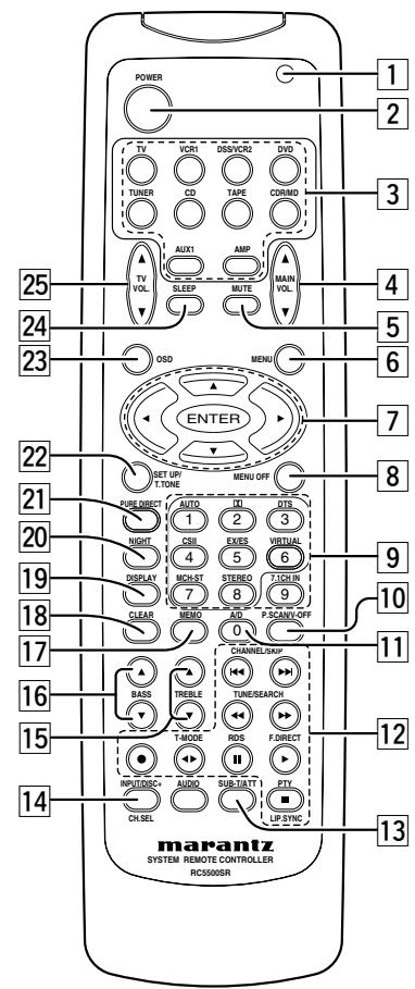
Transmitting indicator
Lights up during a button is pressed and an infrared signal is sending.
(Main) POWER buttons
(when AMP mode is selected)
Press to switch the power of the SR5500 ON or OFF after pressing the AMP button.
3 Input selector buttons/ FUNCTION SELECTOR buttons (AUDIO/VIDEO INPUT)
These buttons are used to select a Audio or Video source component. Press one of these buttons once to change the function of the remote control. Press same button within 2 seconds, the input function of the SR5500 is changed.
Audio function sources such as CD, TAPE, CDR/ MD, and TUNER may be selected in conjunction with a Video source.
This feature (Sound Injection) combines a sound from one source with a picture from another.
Choose the video source first, and then choose a different audio source to activate this function.
Notes:
- CDR/MD button is set CDR function at initial. To switch MD function, press and hold down CDR/MD button and press 2 button.
- To return CDR function, press and hold down CDR/MD button and press 1 button.
4 MAIN VOLUME UP (▲)/DOWN (▼) buttons
Main volume control of the SR5500. The front, surround, center and subwoofer channel volumes controlled by these buttons simultaneously.
MUTE button
Muting button of the SR5500. Press this button decrease the sound temporarily. Press this button again to return to the previous sound.
When this button is pressed, "MUTE" indicator lights up.
6 MENU button
(when AMP mode is selected)
This button is used to enter the SETUP MAIN MENU.
7 Cursor ( , , ,) /ENTER buttons
(when AMP mode is selected)
Use these button when operating the SETUP MAIN MENU.
8 MENU OFF button
(when AMP mode is selected)
This button is used to exit from the SETUP MAIN MENU.
9 Numeric buttons 1 to 9 / Surround mode buttons
Numeric buttons
These buttons are used to enter figures in the selection of a tuner preset station and station name preset or to set select a CD track number, etc. The functions of these buttons are dependent on the function button selected.
Surround mode buttons
(when AMP mode is selected)
These buttons are used to select the surround mode.
10 P.SCAN (Preset scan) / V(Video)-OFF button
(when TUNER mode is selected)
This button is used to start preset scan when SR5500 is selected TUNER mode.
(when AMP mode is selected)
This is used when switching the video signals from the various monitor outputs to Video-Off mode. (See page 27)
11 0/A/D button
0 button
This button is used to enter the number "0"
A/D button (when AMP mode is selected)
This is used to switch between the analog and digital inputs.
12 CONTROL buttons
These buttons are used when operating the CD player, TAPE deck, etc.
The function of these buttons are dependent on the function button selected.
For the controllable functions of each input function, please refer to controllable function table on the page 10.
13 SUB-T (Title) / ATT (attenuator) button
When the input signal is too high and the voice distorts even while adjusting the SR5500 VOLUME control, turn on this function. "ATT" is illuminated when this function is activated.
The input level is reduced. Attenuator is invalid for the output signal of "REC OUT". (See page 27)
Note:
- This function is unavailable while the digital input is selected.
14 INPUT/DISC+ / CH.SEL buttons
This button is used to enter the 7.1 channel input level setup menu.
15 TREBLE UP (▲)/DOWN (▼) buttons
These buttons are used to adjust the tone control of high frequency sound for left and right speaker.
16 BASS UP (▲)/DOWN (▼) buttons
These buttons are used to adjust the tone control of low frequency sound for left, right and subwoofer speaker.
17 MEMO button
Memory enable button for various preset functions.
18 CLEAR button
This button is used to cancel for certain memory or programming operations.
19 DISPLAY button
Selects the display mode for the front display of the SR5500.
20 NIGHT button
Pressing this button prevents the Dolby Digital signal from playback at a loud voice. This function reduces the voice by 1/3 to 1/4 at maximum. Thus, it eliminates the occurrence of an abruptly loud voice at night. However, the function is valid only in the case when the Dolby Digital signal is entered into OPTICAL or COAXIAL and data to compress the voice exists in the signal to be played back.
When this button is pressed, the "NIGHT" indicator is illuminated.
HSITONE
21 PURE DIRECT button
When this button is pressed, the tone control circuit is bypassed.
22 SETUP/T.TONE button
(when AMP mode is selected)
Used to enter the test tone menu.
23 OSD button
(when AMP mode is selected)
When this button is pressed, the current setting is displayed on the TV monitor.
24 SLEEP (sleep timer) button
This button is used for setting the sleep timer. It can be operated the same way as the button on the unit.
25 TV VOLUME UP () /DOWN () buttons
These buttons increase or decrease TV's volume.
PROGRAMMING THE REMOTE CONTROLLER
The remote controller RC5500SR must be programmed to use the codes for your appliances of different brands. This is done by keying in a 4-digit code or by scanning the codes until the correct one is found. We recommend to using the 4-digit code. This mode is faster and more reliable. The code scanning method should be used only if you cannot find the code for one of your appliances. The codes are listed at the end of this book.
Important:
- Use the remote control buttons for programming, not the buttons of the receiver or other appliances.
- Some codes may be not match your equipment. In this case, your equipment cannot be controlled with this remote controller.
PROGRAMMING WITH THE 4-DIGIT CODE
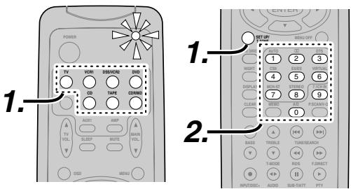
- Press and hold down the Function Selector button for the appliance which should be controlled and press SETUP button until the indicator blinks twice.
- Press the 4-digit code for appliance (code table at the end of this book)
- When the procedure is successful, the indicator will blink twice.
Note:
- If the indicator did not blink twice, then repeat steps 1 through 2 and try entering the same code again.
SCANNING THE CODE TABLE
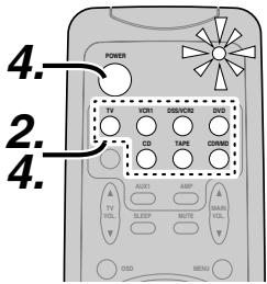
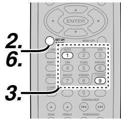
- Switch on the appliance which should be controlled.
- Press and hold down the Function Selector button for appliance which should be controlled and press SETUP button until the indicator blinking twice.
- Press the code 9-9-1.
The indicator will blink twice.
- Aim the remote control at the appliance and slowly alternate between pressing POWER button and the Function Selector button for the appliance.
- Stop when the appliance turns off.
- Press SETUP button once to lock in the code.
CHECKING THE CODE
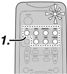
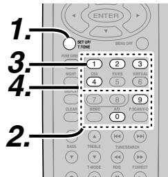
- Press and hold down the Function Selector button for appliance which should be controlled and press SETUP button until the indicator blinking twice.
- Press the code 9 - 9 - 0.
The indicator will blink twice.
- To view the code for first digit, press 1 once. Wait 3 seconds, count the indicator blinks (e.g. 3 blinks = 3) and write down the number.
Note:
- If a code digit is "0", the indicator will not blink.
- Repeat step 3 three more times for remaining digits. Use 2 for the second digit, 3 for the third digit, and 4 for the fourth digit.
RESETTING THE ALL CODE
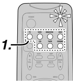
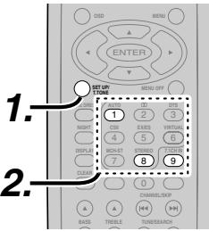
- Press and hold down the any Function Selector button and press SETUP button until the indicator blinking twice.
- Press the code 9-8-1. The indicator will blink twice. Then, RC5500SR will return to the factory preset code.
Note:
- After this procedure, the selected function button is set initial code and other function buttons are set initial code too.
Once you have found and the codes for your various appliances, you may want to write them down here.
TV
VCR
DSS
DVD
CD
TAPE
CDR
MD
The distance between the transmitter of the remote control and the IR SENSOR of the SR5500 should be less than 5 meters. If the remote control is pointed in a direction other than the IR SENSOR or if there is an obstacle between them, use of the remote control may not be possible.
Remote-controllable range
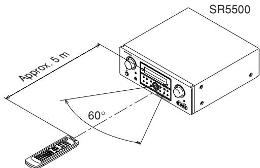
Remote control unit (RC5500SR)
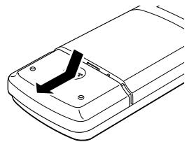
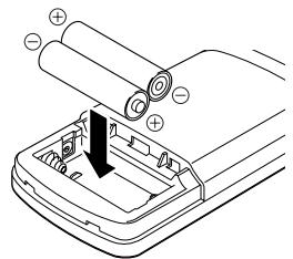
LOADING BATTERIES
The life of the batteries used with the remote control is about 4 months with normal use. Also be sure to replace batteries earlier when you notice that they are getting weak.
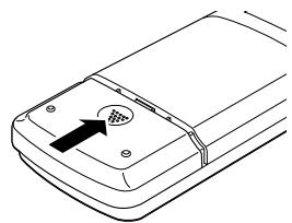
1. Remove the back cover.
2. Insert the new batteries (AAA type) with correct and polarity.
3. Close the cover until it clicks.
Notes:
- Do not mix alkaline and manganese batteries.
- Do not mix old and new batteries.
CAUTIONS ON BATTERIES
- Use "AAA" type batteries in this remote control unit.
- If the remote control unit does not operate from close to the main unit, replace the batteries with new ones, even if less then a year has passed.
- The included battery is only for verifying operation. Replace it with a new battery as soon as possible.
- When inserting the batteries, be careful to do so in the proper direction, following the + and - marks in the remote control unit's battery compartment.
-
To prevent damage or battery fluid leakage:
-
Do not use a new battery with an old one.
- Do not use two different types of batteries.
-
Do not short-circuit, disassemble, heat or dispose of batteries in flames.
-
Remove the batteries when not planning to use the remote control unit for a long period of time.
- If the batteries should leak, carefully wipe off the fluid from the inside of the battery compartment, then insert new batteries.
- When disposing of used batteries, please comply with governmental regulations or environmental public instruction's rules that apply in your country or area.
GENERAL INFORMATION OF RC5500SR TO SR5500
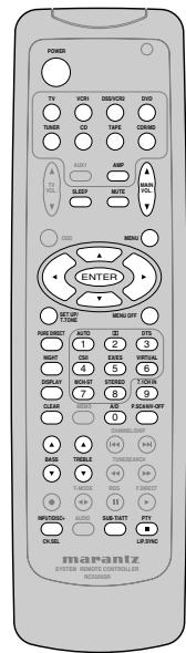
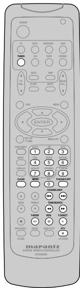
To control the SR5500 by your RC5500SR, you have to select the device AMP or TUNER by pressing the function selector button. Please refer below for the details in AMP and TUNER mode.
AMP MODE
TUNER MODE
| POWER | Turns the SR5500 on and off |
| Function selector * | Selects a particular source component |
| SLEEP * | Sets the sleep timer function |
| MUTE * | Decreases the sound temporarily |
| VOL ▲▼* | Adjusts the over all sound level |
| MENU | Enters the SETUP MENU |
| Cursor | Moves the cursor for settings in the SETUP MENU |
| ENTER | • Enters the SETUP MENU • Confirms the settings in SETUP MENU |
| SETUP/T.TONE | Enters the test tone mode for setting the Speaker Level Setup |
| MENU OFF | Exits from the SETUP MENU |
| PURE DIRECT * | Selects the Pure Direct mode |
| NIGHT * | Turns on or off the NIGHT mode |
| DISPLAY * | Change the front display mode |
| Surround mode (1-8) | Selects the surround mode |
| 7.1CH-IN (9) | Selects the 7.1CH IN |
| A/D (0) | Switches between the analog and digital inputs |
| BASS ▲▼* | Adjusts the tone control of low frequency sound |
| TREBLE ▲▼* | Adjusts the tone control of high frequency sound |
| SUB-T/ATT | Reduces the input level |
| P.SCAN/V-OFF | Turns on or off the Video output |
| CH. SEL | Adjusts the 7.1 ch input level |
| LIP.SYNC | Selects the LIP. SYNC mode |
- These buttons are used to control SR5500 in any function mode.
| TUNER | Selects a frequency band |
| 0-9 | Inputs the numeric #s |
| CLEAR | Clears the inputting |
| MEMO | Enters the tuner preset memory numbers |
| P.SCAN/V-OFF | Starts preset scan |
| CHANNEL/SKIP | • Selects a preset station |
| TUNE/SEARCH | Tunes a station |
| T-MODE | • Selects the auto stereo mode or mono mode |
| F.DIRECT | • Selects the "Frequency direct input" |
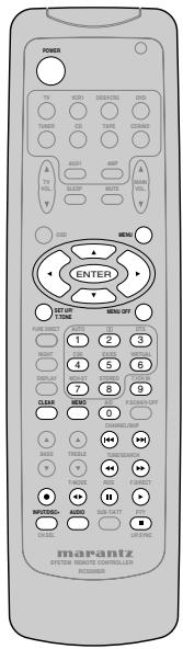
THE CONTRABLE FUNCTION TABLE
| TV | VCR | DVD | DSS | CD | TAPE | CDR | MD | |
| POWER | POWER | POWER | POWER | POWER | POWER | POWER | POWER | POWER |
| MENU | CALL UP MENU | CALL UP MENU | CALL UP MENU | CALL UP MENU | SWITCH DISPLAY | SWITCH DISPLAY | SWITCH DISPLAY | SWITCH DISPLAY |
| Cursor | Cursor | Cursor | Cursor | Cursor | - | - | - | - |
| ENTER | OK | OK | OK | OK | - | - | - | - |
| SETUP/T.TONE | - | - | SETUP MENU | - | - | - | - | - |
| MENU OFF | - | CANCEL MENU | - | CANCEL MENU | - | - | - | - |
| 0 - 9 | INPUT NUMERIC | INPUT NUMERIC | INPUT NUMERIC | INPUT NUMERIC | INPUT NUMERIC | INPUT NUMERIC | INPUT NUMERIC | INPUT NUMERIC |
| CLEAR | INPUT CLEAR | TAPE SPEED | INPUT CLEAR | INPUT CLEAR | INPUT CLEAR | INPUT CLEAR | INPUT CLEAR | INPUT CLEAR |
| MEMO | - | - | CALL PROGRAM | - | CALL PROGRAM | CALL PROGRAM | CALL PROGRAM | CALL PROGRAM |
| CHANNEL/SKIP← | CH- | PREV | PREV | CH- | PREV | PREV | PREV | PREV |
| CHANNEL/SKIP→ | CH+ | NEXT | NEXT | CH+ | NEXT | NEXT | NEXT | NEXT |
| TUNE/SEARCH← | - | REWIND | REWIND | - | REWIND | REWIND | REWIND | REWIND |
| TUNE/SEARCH→ | - | FF | FF | - | FF | FF | FF | FF |
| ●(REC) | - | REC | - | - | - | REC | REC | REC |
| T-MODE← | - | - | - | - | - | DIRECTION | - | - |
| RDS■ | - | PAUSE | PAUSE | - | PAUSE | PAUSE | PAUSE | PAUSE |
| F.DIRECT▼ | - | PLAY | PLAY | - | PLAY | PLAY | PLAY | PLAY |
| INPUT/DISC+ | INPUT SEL. | TV/VCR | DISC+ | TV/DSS | DISC+ | - | DISC+ | - |
| AUDIO | - | AUDIO | AUDIO | AUDIO | - | - | - | - |
| PTY■ | - | STOP | STOP | - | STOP | STOP | STOP | STOP |
| SUB-T/ATT | - | - | SUBTITLE | - | - | - | - | - |
CONNECTIONS
SPEAKER PLACEMENT
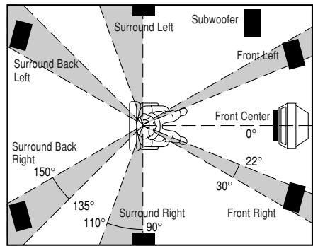
The ideal surround speaker system for this unit is 7-speaker systems, using front left and right speakers, a center speaker, surround left and right speakers, a surround back left and right speakers, and a subwoofer.
For best results we recommend that all front speakers be of the same type, with identical or similar driver units. This will deliver smooth pans across the front sound stage as the action moves from side to side.
Your center channel speaker is very important as over 80% of the dialog from a typical motion picture emanates from the center channel.
It should possess similar sonic characteristics to the main speakers. Surround channel speakers need not be identical to the front channel speakers, but they should be of high quality.
The surround center speaker is useful for playback of Dolby Digital Surround EX or DTS-ES. One of the benefits of both Dolby Digital and DTS is that surround channels are discrete full range, while they were frequency limited in earlier "Pro Logic" type systems.
Bass effects are an important part of home theater. For optimal enjoyment a subwoofer should be used as it is optimized for low frequency reproduction. If you have full range front speakers, however, they may be used in place of a subwoofer with proper setting of the switches in the menu system.
Front left and right speakers
We recommend to set the front L and R speakers with 45-60 degrees from the listening position.
Center speaker
Align the front line of the center speaker with the front L/R speakers. Or place the center speaker a little backward from the line.
Surround left and right speakers
When the SR5500 is used in surround operation, the preferred location for surround speakers is on the side walls of the room, at or slightly behind the listening position.
The center of the speaker should face into the room.
Surround back left and right speakers
Surround back speakers are required when a full 7.1-channel system is installed.
Speakers should be placed on a rear wall, behind the listening position.
The center of the speaker should face into the room.
Subwoofer
We recommend using a sub-woofer to have maximum bass effect. Sub-woofer bears only low frequency range so you can place it any where in the room.
HEIGHT OF THE SPEAKER UNITS
Front left and right speakers, and a center speaker Align the tweeters and mid-range drivers on the three front speakers at the same height, as best as possible.
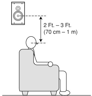
Surround left and right speakers, and surround back speaker
Place the surround left, right and surround back speakers higher than your ears by about 2 Ft. -3 Ft. (70cm - 1m) . Also place the speakers at the same height, as best as possible.
Note:
- Use magnetically-shielded speakers for front left, right and the center speakers when the speakers are installed near the TV and the TV is a monitor type.
CONNECTING SPEAKERS
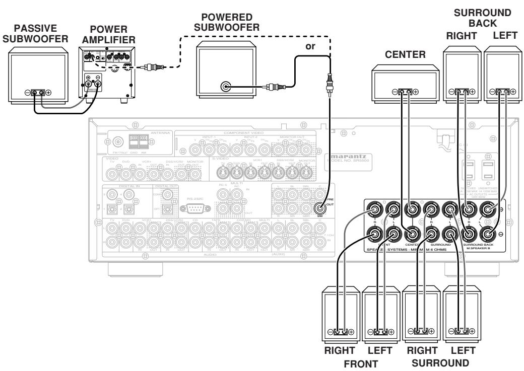
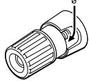
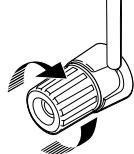
CONNECTING SPEAKER WIRE
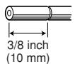
- Strip away approx. 3/8 inch (10 mm) of wire insulation.
- Twist the bared wire ends tight, to prevent short circuits.
- Loosen the knob by turning it counterclockwise.
- Insert the bare part of the wire into the hole in side of each terminal.
- Tighten the knob by turning it clockwise to secure the wire.
1.
2.

4.
5.
Caution:
- Be sure to use speakers with the specified impedance as shown on the rear panel of this unit.
- To prevent damage to circuitry, do not let the bare speaker wires touch each other and do not let them touch any metal part of this unit.
- Do not touch the speaker terminals when the power is on. It may cause you to receive an el
- Do not connect more than one speaker cable to one speaker terminal. Doing so may damage this unit.
Note:
- Be sure to connect the positive and negative cables for the speaker properly. If they are misconnected, the signal phase will be reversed and the signal quality will be corrupted.
CONNECTING A SUBWOOFER
Use the PRE OUT SUBWOOFER jack to connect a powered subwoofer (power amplifier built in).
If your subwoofer is a passive type (power amplifier is not built in), connect a monaural power amplifier to the PRE OUT SUBWOOFER jack and connect the subwoofer to the amplifier.
CONNECTING AUDIO COMPONENTS
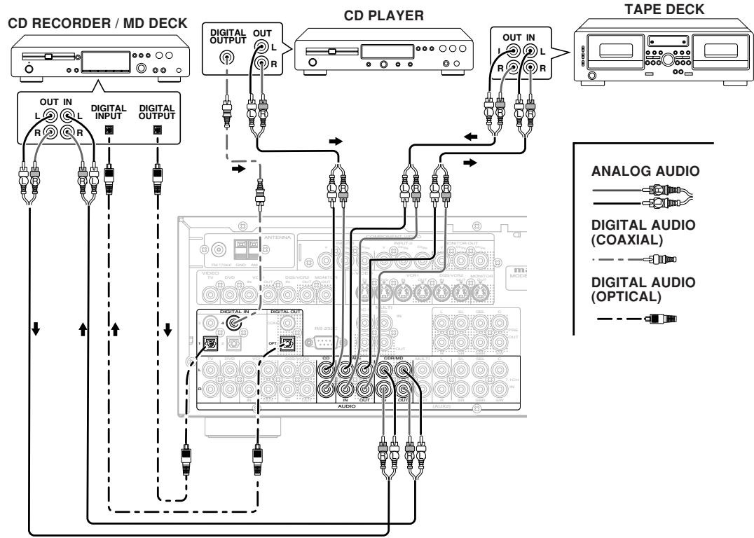
The output audio signal from the TAPE OUT jack and the CD-R/MD OUT jack is the same signal which is currently selected.
Caution:
- Do not connect this unit and other components to mains power until all connections between components have been completed.
Notes:
- Insert all plugs and connectors securely. Incomplete connections may make noise.
- Be sure to connect the left and right channels properly.
Red connectors are for the R (right) channel, and white connectors are for the L (left) channel.
- Be sure to connect input and output properly.
- Refer to the instructions for each component that is connected to this unit.
- Do not bind audio/video connection cables with power cords and speaker cables this will result in generating a hum or other noise.
CONNECTING DIGITAL AUDIO COMPONENTS
- There are 4 digital inputs, 2 coaxial jacks and 2 optical jacks, on the rear panel. You can use these jacks to input PCM, Dolby Digital and DTS bitstream signals from a CD, DVD, or other digital source components.
- There is one digital output coaxial jack and one optical output jack on the rear panel. These jacks can be connected to a CD recorder-, or a MD deck inputs, respectively.
- Refer to the instructions for each component. To setup the digital audio format of DVD player, or other digital source's connected to digital input jacks.
- Use fiber optical cables (optical) for DIG-1,2 input jacks. Use 75 ohms coaxial cables (for digital audio or video) for DIG-3, 4 input jacks.
- You can designate the input for each digital input/output jacks according to your component. See page 18.
Notes:
- There is no Dolby Digital RF input jack. Please use an external RF demodulator Dolby Digital decoder when connecting the Dolby Digital RF output jack of the video disc player to the digital input jack.
- The digital signal jacks on this unit conform to the EIA standard. If you use a cable that does not conform to this standard, this unit may not function properly.
Each type of audio jack works independently. Signals input through the digital and analog jacks are output through the corresponding digital and analog jacks, respectively.
CONNECTINGVIDEOCOMPONENTS
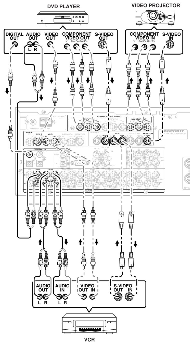
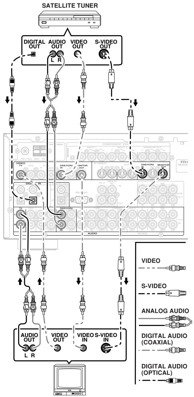
TV
VIDEO.S-VIDEO,.COMPONENTJACKS
There are 3 types of video jacks on the rear panel.
VIDEO jack
The video signal for the VIDEO jacks is the conventional composite video signal.
S-VIDEO jack
The video signal is separated into luminance (Y) and color (C) signals for the S-VIDEO jack. The S-VIDEO signals enables high-quality color reproduction. If your video component has an S-VIDEO output, we recommend to use it. Connect the S-VIDEO output jack on your video component to the S-VIDEO input jack on this unit.
Component jack
Make component video connections to a TV or monitor with component inputs to produce higher quality video images. Use a component video cable or 3 video cords to connect the component video out jacks on the SR5500 to the monitor.
Notes:
- Be sure to connect the left and right audio channels properly.
Red connectors are for the R (right) channel, and white connectors are the for L (left) channel. - Be sure to connect the inputs and outputs of the video signals properly.
- If you connect the S-VIDEO or component signal to the S-VIDEO or component jack on this unit, it is not necessary to connect the conventional video signal to the VIDEO (composite) jack. If you use both video inputs, this unit gives priority to the S-VIDEO signal.
Each type of video jack works independently. Signals input to the VIDEO (composite) and SVIDEO jacks or component are output to the corresponding VIDEO (composite) and S-VIDEO or component jacks, respectively. - This unit has the "TV-AUTO ON/OFF" function to turn the TV ON or OFF automatically, by sensing the incoming video signal from the VIDEO jacks.
- You may need to setup the digital audio output format of your DVD player, or other digital source components. Refer to the instructions of the each component connected to the digital input jacks.
- There is no Dolby Digital RF input jack. Please use an external RF demodulator with a Dolby Digital decoder to connect a video disc player which has a Dolby Digital RF output jack to the digital input jack on this unit.
ADVANCED CONNECTING
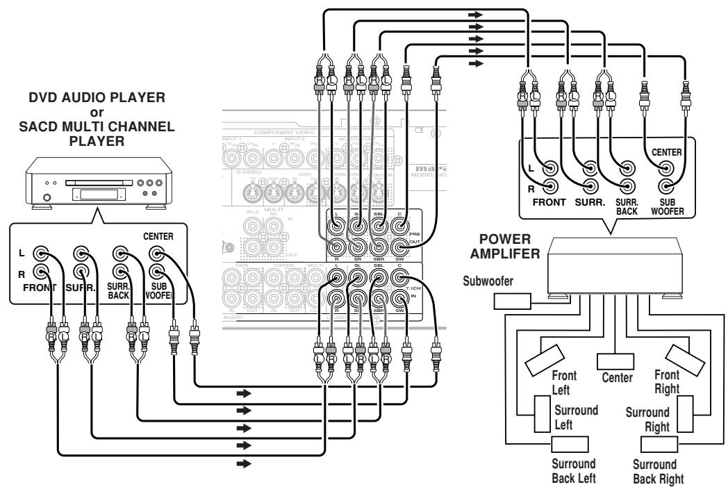
CONNECTING MULTI CHANNEL AUDIO SOURCE
The 7.1CH INPUT jacks are for multichannel audio source such as a SACD multichannel player, DVD audio player or external decoder. If you use these jacks, switch on the 7.1CH INPUT and set the 7.1CH INPUT level by using the SETUP MAIN MENU. See page 28.
CONNECTING AN EXTERNAL POWER AMPLIFIER
The PREOUT jacks are for connecting external power amplifiers.
Be sure to connect each speaker to the corresponding external power amplifier.
CONNECTING THE REMOTE CONTROL JACKS
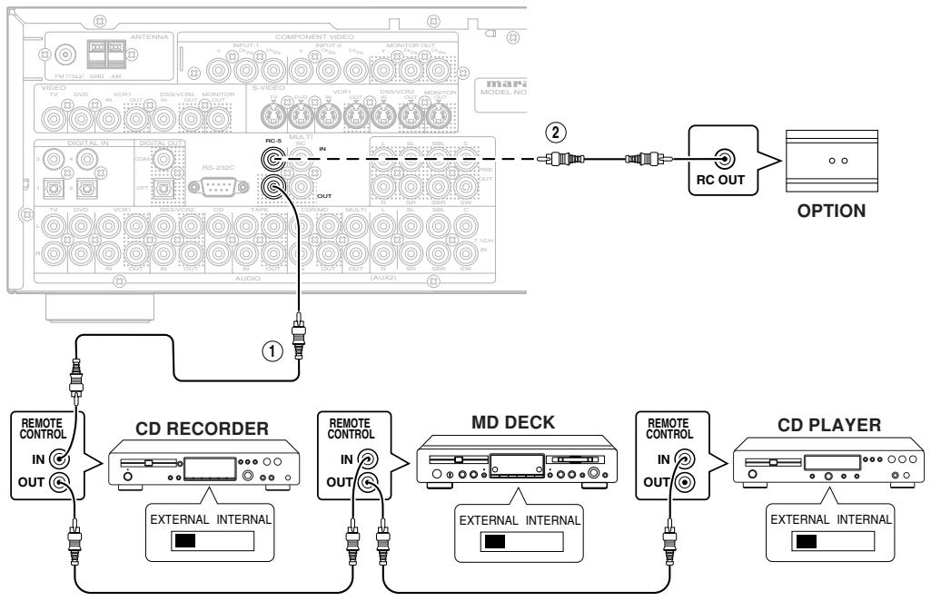

You can control other Marantz products through this unit with the remote control by connecting the REMOTE CONTROL terminals on each unit.
The signal transmitted from the remote control is received by the remote sensor on this unit. Then the signal is sent to the connected device through this terminal. Therefore you need to aim the remote signal only to the unit. Also, if a Marantz power amplifier (some models excluded) is connected to one of these terminals, the power amplifier's, power switch is synchronized with this unit's power switch.
Set the REMOTE CONTROL SWITCH on the units, other than the main unit to EXT.(EXTERNAL) for this feature.

Whenever external infrared sensors or similar devices are connected to RC-5 IN of the SR500, be sure to always disable operation of the infrared sensor on the main unit by using the following procedure.
- Hold down the 7.1CH INPUT button and MENU button on the front panel at the same time for five seconds.
- The setting "IR=ENABLE" is shown on the FL DISPLAY.
- Press the or cursor button to change this to "IR=DISABLE".
- Press the ENTER button. Once this setting is made, the infrared sensor on the main unit is disabled.
Note:
-
Be sure to set to "IR=ENABLE" when external infrared sensors or similar devices are not connected. Otherwise, the main unit will be unable to receive remote control commands.
-
To restore the original setting, perform steps 1 to 4 to set to "IR=ENABLE".
CONNECTING THE ANTENNA TERMINALS
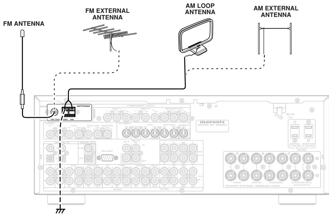
ASSEMBLING THE AM LOOP ANTENNA
- Release the vinyl tie and take out the connection line.
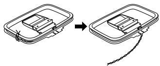
- Place the antenna on stable surface.
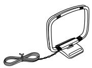
- Bend the base part in the reverse direction.
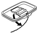
- Insert the hook at the bottom of the loop part into the slot at the base part.
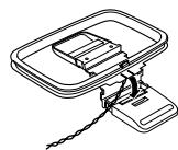
CONNECTING THE SUPPLIED ANTENNAS
Connecting the supplied FM antenna
The supplied FM antenna is for indoor use only. During use, extend the antenna and move it in various directions until the clearest signal is received. Fix it with push pins or similar implements in the position that will cause the least amount of distortion. If you experience poor reception quality, an outdoor antenna may improve the quality.
Connecting the supplied AM loop antenna
The supplied AM loop antenna is for indoor use only.
Set it in the direction and position it to where you receive the clearest sound. Put it as far away as possible from the unit, televisions, speaker cables, and power cords.
If you experience poor reception quality, an outdoor antenna may improve the quality.
- Press and hold down the lever of the AM antenna terminal.
- Insert the bare wire into the antenna terminal.
- Release the lever.
CONNECTING AN FM OUTDOOR ANTENNA
Notes:
- Keep the antenna away from noise sources (neon signs, busy roads, etc.).
- Do not put the antenna close to power lines. Keep it well away from power lines, transformers, etc.
- To avoid the risk of lightning and electrical shock, grounding is necessary.
CONNECTING AN AM OUTDOOR ANTENNA
An outdoor antenna will be more effective if it is stretched horizontally above a window or outside.
Notes:
- Do not remove the AM loop antenna.
- To avoid the risk of lightning and electrical shock, grounding is necessary.
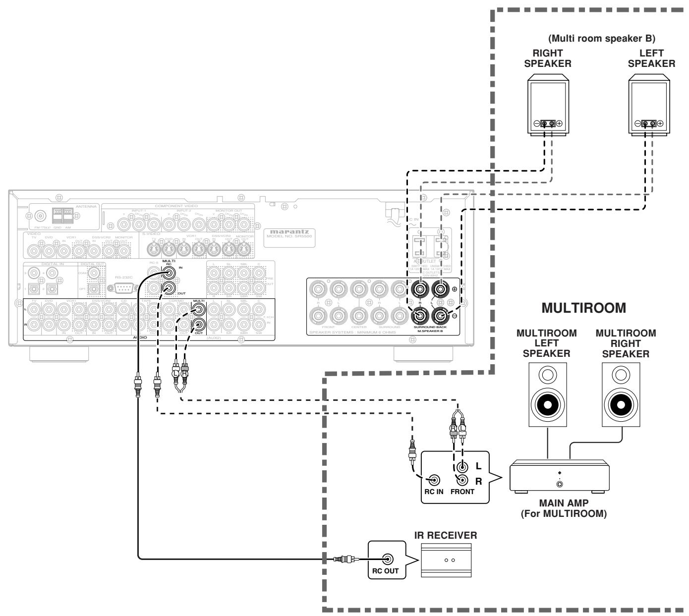
Note:
- You can use surround back speaker terminals as multi room speaker terminals when you use no surround back speaker.
SETUP
After all components are connected, initial setup must be performed.
The SR5500 incorporates an on-screen menu system, which makes various operations possible by using the cursor (▲,▼,▲,▶) and ENTER buttons on the remote control or on the front panel.
Note:
-
To view the on-screen displays, make certain you have made a connection from the Monitor Out jack on the rear panel to the composite, S-Video, component video input of your TV or projector. (see page 13)
-
Press the AMP button of the remote control. (This step is not needed when operating the setup menus from the receiver itself.)
- Press the MENU button on the remote control or set to display the "SETUP MAIN MENU" of the OSD menu system.
There are 8 items in the SETUP MAIN MENU.
- Select a desired sub-menu with the or cursor buttons, and press the ENTER button to enter. The display will change to the selected sub-menu. You can lock the condition of setup to each sub-menu with the or or cursor buttons.
Note:
-
If you desire to adjust any sub-menu, you need to set it to UNLOCKED.
-
If you desire to exit from this menu system, press the EXIT button, or move the cursor to EXIT and press the ENTER button.
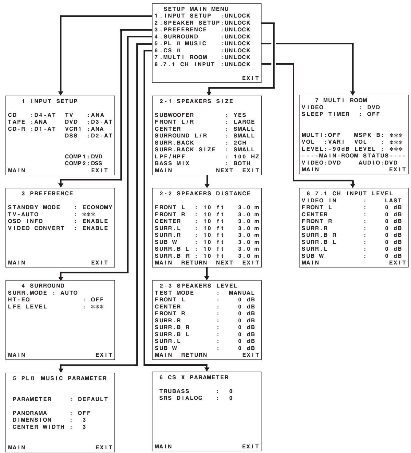
HSITONE
1 INPUT SETUP (ASSIGNABLE DIGITAL INPUT AND COMPONENT VIDEO INPUT)
4 digital inputs and 2 component video inputs can be assigned to a desired source.
Use this menu to select the digital input jack to be assigned to the input source.
- Select "INPUT SETUP" in SETUP MAIN MENU with or cursor button, and press the ENTER button.
Select "Dx-AT" for input sources, for automatic detection of the digital input signal condition. If there is not a digital signal present, but there is an analog signal present, the analog signal will be played.
Select "Dig x", when only a digital signal will be used. Select "ANA" for input sources for which no digital input jacks are used.
- To select the video source, select "COMP1" or "COMP2" by pressing the or cursor buttons, and press the or cursor buttons to select the video source to be assigned.
- After you complete this portion of the set up, move the cursor to MAIN with the or cursor buttons and press the ENTER button.
Notes:
- The TUNER, AUX1 and AUX2 are fixed to the analog input, and cannot be selected for any digital input.
- When a DTS-LD or DTS-CD is playing, this setup is not available. This is to avoid noise being generated from the analog input.
- If "Dx-AT" is selected and a DVD, compact disc or LD is fast-forwarded during playback, decoded signals may produce a skipping sound. In such cases, change the setting to DIGITAL.
2 SPEAKER SETUP
After you have installed the SR5500, connected all the components, and determined the speaker layout, it is now time to perform the settings in the Speaker Setup menu for the optimum sound acoustics for your environment and speaker layout.
Before you perform the following settings, it is important that you first determine the following characteristics:
2-1 SPEAKERS SIZE
When setting the speaker size in the SPEAKER SIZE sub-menu, use the guidelines given below.
LARGE:
The complete frequency range for the channel you are setting will be output from the speaker.
SMALL:
- Frequencies of the channel you are setting lower than approx. 100Hz will be output from the subwoofer.
If the Subwoofer is set to "NONE" and the front speakers are set to "LARGE," then the sound will be output from both the left and right speakers.
2-1 SPEAKERS SIZE
| SUBWOOFER | : YES |
| FRONT L/R | : LARGE |
| CENTER | : SMALL |
| SURROUND L/R | : SMALL |
| SURR.BACK | : 2CH |
| SURR.Back SIZE | : SMALL |
| LPF/HPF | : 100 HZ |
| BASS MIX | : BOTH |
| MAIN | NEXT EXIT |
- Select "SPEAKER SETUP" in SETUP MAIN MENU with or cursor button, and press the ENTER button.
- To select the each speaker, press the or cursor buttons.
- To select the setting of each speaker size, press the or cursor buttons.
- After you complete this portion of the set up, move the cursor to "NEXT" with the or cursor buttons and then press the ENTER button to go to the next page.
SUBWOOFER:
YES:
Select when a subwoofer is connected.
NONE:
Select when a subwoofer is not connected.
FRONT L/R
LARGE:
Select if the front speakers are large.
SMALL:
Select if the front speakers are small.
- If "NONE" is selected for the Subwoofer setting, then this setting is fixed to "LARGE."
CENTER
NONE:
Select if no center speaker is connected.
LARGE:
Select if the center speaker is large.
SMALL:
Select if the center speaker is small.
SURROUND L/R
NONE:
Select if no surround left and right speakers are connected.
LARGE:
Select if the surround left and right speakers are large.
SMALL:
Select if the surround left and right speakers are small.
SURR. BACK
NONE:
Select if no surround back left and right speakers are connected.
2CH:
Select if the surround back left and right speakers are connected.
1CH:
Select if the one surround back speaker is connected.
In this case, the audio signal is emitted form the Surround L output terminal.
Notes:
- If "NONE" is selected for the Surround L/R setting, then this setting is fixed to "NONE."
- You can use surround back speaker terminals as multi room speaker terminals when you use no surround back speaker. (See page 16)
SURR. BACK SIZE
LARGE:
Select if the surround back speaker is large.
SMALL:
Select if the surround back speaker is small.
Note:
- If "NONE" is selected for the Surround L/R setting, then this setting is not available.
LPF/HPF
When you use a subwoofer, you can select the cutoff frequency for the small speakers used. Select one of the crossover frequency levels according to the size of the small speaker connected.
80Hz:
Select this when the bass speaker is about 12 cm (4 3/4 inches).
100Hz:
Select this when the bass speaker is about 10 cm (3 15/16 inches).
120Hz
Select this when the bass speaker is about 8 cm (3 3/16 inches).
Notes:
- Use the above comments as reference when adjusting.
- If Pure-Direct mode, 7.1CH Input is in use, this function does not take effect.
BASS MIX
- The bass mix setting is only valid when "LARGE" is set for the front speakers and "YES" is set for the subwoofer during stereo playback.
This setting has effect only during playback of PCM or analog stereo sources.
- When "BOTH" is selected, the low frequencies will be played through the main L&R, as well as the sub woofer.
In this playback mode, the low frequency range expand more uniformly through the room, but depending on the size and shape of the room, interference may result in a decrease of the actual volume of the low frequency range.
- By selecting "MIX", the low frequencies will play through the main L&R ONLY.
Note:
- LFE signals during playback of Dolby Digital or DTS, will be played through the subwoofer.
2-2 SPEAKERS DISTANCE
Use this parameter to specify the distance of each speaker's position from the listening position. The delay time is automatically calculated according to these distances.
Begin by determining the ideal or most commonly used seating position in the room.
This is important for the timing of the acoustics to create the proper sound space that the SR5500 and today's sound systems are able to produce.
Note:
- For speakers that you have selected "NONE" the Speaker Configuration sub-menu will not appear here. (There are several useful books and special DVD and LD's available to guide you through proper home theater configuration. If you are unsure, have your Marantz dealer perform the installation for you. They are trained professionals familiar with even the most sophisticated custom installations. Marantz recommends the WWW.CEDIA.ORG website for further information about this).
2-2 SPEAKERS DISTANCE
| FRONT L : 10 f t 3.0 m |
| FRONT R : 10 f t 3.0 m |
| CENTER : 10 f t 3.0 m |
| SURR.L : 10 f t 3.0 m |
| SURR.R : 10 f t 3.0 m |
| SUB W : 10 f t 3.0 m |
| SURR.B L : 10 f t 3.0 m |
| SURR.B R : 10 f t 3.0 m |
| MAIN RETURN NEXT EXIT |
- To select each speaker, press the or cursor buttons.
- To set the distance for each speaker, press the or cursor buttons.
- After you complete this portion of the set up, move the cursor to "NEXT" with the or cursor buttons and then press the ENTER button to go to the next page.
FRONT L:
Set the distance from the front left speaker to your normal listening position between 1 and 30 feet in 1.0 foot intervals (0.3 to 9 meters in 0.3-meter intervals).
FRONT R:
Set the distance from the front right speaker to your normal listening position between 1 and 30 feet in 1.0 foot intervals (0.3 to 9 meters in 0.3-meter intervals).
CENTER:
Set the distance from the center speaker to your normal listening position between 1 and 30 feet in 1.0 foot intervals (0.3 to 9 meters in 0.3-meter intervals).
SUBR.L:
Set the distance from the surround left speaker to your normal listening position between 1 and 30 feet in 1.0 foot intervals (0.3 to 9 meters in 0.3-meter intervals).
SURR. R:
Set the distance from the surround right speaker to your normal listening position between 1 and 30 feet in 1.0 foot intervals (0.3 to 9 meters in 0.3-meter intervals).
SUB W:
Set the distance from the subwoofer to your normal listening position between 1 and 30 feet in 1.0-foot intervals (0.3 to 9 meters in 0.3-meter intervals).
SURR.BL:
Set the distance from the surround back left speaker to your normal listening position between 1 and 30 feet in 1.0-foot intervals (0.3 to 9 meters in 0.3-meter intervals).
SURR.BR:
Set the distance from the surround back right speaker to your normal listening position between 1 and 30 feet in 1.0-foot intervals (0.3 to 9 meters in 0.3-meter intervals).
Notes:
- For the speakers that you have selected "NONE" the Speaker Size menu will not appear.
- The setting for Surr.Back L and Surr.Back R appears if you set for it to, two surround back speakers in the Speaker Size menu.
- The setting of Surr.Back appears if it is set for one surround back speaker in the Speaker Size menu.
2-3 SPEAKERS LEVEL
Here you will set the volume for each speaker so that they are all heard by the listener at the same level. We recommend using a SPL (Sound Pressure Level) meter, when available.
Note:
- The speaker level settings are not available in 7.1 channel input mode and Pure-Direct mode.
| 2-3 SPEAKERS LEVEL | |
| TEST MODE : MANUAL | |
| FRONT L : 0 dB | |
| CENTER : 0 dB | |
| FRONT R : 0 dB | |
| SURR.R : 0 dB | |
| SURR.B R : 0 dB | |
| SURR.B L : 0 dB | |
| SURR.L : 0 dB | |
| SUB W : 0 dB | |
| MAIN RETURN EXIT |
TEST MODE :
Selects "MANUAL" or "AUTO" for generating the mode of the test tone with the or cursor buttons.
If you select "AUTO", the test tone will be cycled through in a circular pattern which is Left Center Right Surround Right Surround Back Right Surround Back Left Surround Left Subwoofer Left . increments of 3 seconds for each channel.
Using the or cursor buttons, adjust the volume level of the noise from the speaker so that it is the same level for all the speakers.
If you select "MANUAL", adjust the output level of each speaker as listed below.
- When you move the cursor to FRONT L by pressing the cursor button, the SR5500 will emit a pink noise from the front left speaker. Remember the level of this noise and then press the cursor button.
(Note that this can be adjusted to any level between -10 and +10 dB in 1 dB intervals except the subwoofer setting. The subwoofer can be adjusted to any level between -15 and +10 dB in 1 dB intervals.)
The SR5500 will now emit the pink noise from the center speaker. - Using the and cursor buttons, adjust the volume level of the noise from the center speaker so that it is the same level as the front left speaker.
- Press the cursor button again. The SR5500 will now emit the pink noise from the front right speaker.
- Repeat steps 2 and 3 above for the front right and other speakers until all speakers are adjusted to the same volume level.
After you complete this portion of the set up, press the ENTER button, the cursor will move to "MAIN" and then press the ENTER button to go to SETUP MAIN MENU.
Notes:
- Speakers that you selected "NONE" for in the Speaker Size menu will not appear.
- The setting of Surr.Back L and Surr.Back R appears if you have set it for two surround back speakers in the Speaker Size menu.
- The setting of Surr.Back appears if you have set it for one surround back speaker in the Speaker Size menu.
- To adjust the speaker levels for 7.1-channel input sources, you will need to use the 7.1CH-INPUT sub menu. (See page 21).
3 PREFERENCE
3 PREFERENCE
STANDBY MODE : ECONOMY TV-AUTO : ***
OSD INFO : ENABLEVIDEOCONVERT : ENABLE
MAIN EXIT
- Select "PREFERENCE" in the SETUP MAIN MENU with the or cursor buttons, and press the ENTER button.
- To select a desired content, press the or cursor buttons.
STANDBY MODE:
When this function is set to "ECONOMY", you can reduce the power consumption when the unit is in the standby mode.
Note:
- TV-AUTO and RS-232C are disabled in the "ECONOMY" setting.
TV AUTO:
Select the TV AUTO ON/OFF function to enable or disable with the or cursor buttons. (refer to page 27)
OSD Info:
Select the OSD information function to enable or disable with the or cursor buttons.
If you select "ENABLE", the SR5500 will display the status of the feature (Volume up/down, input select, etc.) on the TV monitor. But if you do not desire this information, select "DISABLE".
VIDEO CONVERT:
Select theVIDEOCONVERT function to enable or disable with the or cursor buttons. (Video cable connection: Refer to page 23)
After you complete this portion of the set up, move the cursor to "MAIN" with the or cursor buttons and press the ENTER button.
HSITONE
4 SURROUND
4 SURROUND
SURR_MODE : AUTO
HT-EQ : OFF
LFE_LEVEL : 0 dB
MAIN EXI
- Select "SURROUND" in the SETUP MAIN MENU with the or cursor buttons, and press the ENTER button.
- To select a desired content, press the or cursor buttons.
SURR Modes:
Select the desired surround mode with the or cursor buttons.
HT-EQ:
Select to active the HT-EQ with the or cursor buttons.
The tonal balance of a film soundtrack will be excessively bright and harsh when played back over audio equipment in the home. This is because film soundtracks were designed to be played back in large movie theater environments. Activating the HT-EQ feature when watching a film made for movie theaters corrects this and restores the correct tonal balance.
The HT-EQ feature is available except in the following modes.
- 7.1 CH INPUT
- PURE-DIRECT
- When VIRTUAL is set for the surround mode
LFE LEVEL:
Select the output level of the LFE signal included in the Dolby Digital signal or the DTS signal. Select 0 dB, -10 dB or OFF with the or cursor buttons.
After you complete this portion of the set up, move the cursor to "MAIN" with the or cursor buttons and press the ENTER button.
5 PL II (PRO LOGIC II) MUSIC PARAMETER
Pro Logic II-Music mode creates a rich and enveloping surround ambience from stereo sources such as CDs.
In this mode, SR5500 includes three controls to fine-tune the soundfield as follows.
5 PLII MUSIC PARAMETER
PARAMETER : DEFAULT
PANorama : OFF
DIMENSION 3
CENTERWIDTH:3
MAIN EXIT
Select "PL II MUSIC" in the SETUP MAIN MENU with the or cursor buttons, and press the ENTER button.
PARAMETER:
Select "DEFAULT" or "CUSTOM" with the or cursor buttons.
If you select "CUSTOM", you can adjust three parameters as listed below.
PANorama:
Select the Panorama mode On or Off with the or cursor buttons.
Panorama wraps the sound of the front left and right speakers around you, for an exciting perspective.
DIMENSION:
Set the Dimension level between 0 and 6 level in 1 level intervals with the or cursor buttons.
Adjust the soundfield either towards the front or towards the rear.
This can be useful to help achieve a more suitable balance from all the speakers with certain recordings.
CENTERWIDTH:
Set the Center width level between 0 and 7 in 1 level intervals with the or cursor buttons.
Center Width allows you to gradually spread the center channel sound into the front left and right speakers.
At its widest setting, all the sound from the center is mixed into the left and right.
This control may help achieve a more spacious sound or a better blend for the front image.
If "NONE" was selected for the Center speaker setting, in the Speaker size set up menu, then this setting will not appear.
After you complete this portion of the set up, move cursor to "MAIN" with the or cursor buttons and press the ENTER button.
6 CS II (CIRCLE SURROUND II) PARAMETER
6 CS II PARAMETER
TRUBASS 0 SRS DIALOG 0
MAIN EXIT
- Select "CS II" in the SETUP MAIN MENU with the or cursor buttons, and press the ENTER button.
- To Select desired contents as below, press the or cursor buttons.
TRUBASS:
Set the TRUBASS level between 0 and 6 level in 1 level interval with the or cursor buttons. TRUBASS produced by the speakers are an octave below the actual physical capabilities of the speakers adding exciting, deeper bass effects.
SRS DIALOG:
Set the SRS DIALOG level between 0 and 6 in 1 level intervals with the or cursor buttons.
This can be popped out of the surround audio effects, allowing the listener to easily discern what the actors say.
If "NONE" was selected for the Center speaker setting, in the Speaker size set up menu, then this setting will not appear.
After you complete this portion of the set up, move cursor to "MAIN" with the or cursor buttons and press the ENTER button.
7 MULTI ROOM
SR5500 has features in MULTI ROOM SYSTEM such as source selector, sleep timer, Multi Room Speaker output and remote control.
You can set these feature in this sub-menu.
7 MULTI ROOM AUDIO : DVD SLEEP TIMER : OFF
MULTI:OFF MSPKB:***
Select the audio source of the Multi-room output with or cursor buttons.
SLEEP TIMER:
SLEEP timer function is available during the multiroom is active, set the time with or cursor buttons.
MULTI (MULTI ROOM):
To switch on the Multi-room output ON or OFF, press or cursor button.
VOL (VOLUME SETUP):
Select whether the Multi-room output level is variable or fixed with a or cursor buttons.
LEVEL (VOLUME LEVEL):
Adjust the Multi-room output level with or cursor buttons.
MSPK B (MULTI SPEAKER B):
To switch on the Multi-speaker B output ON or OFF, press or cursor buttons.
Note:
- This setting can be changed when the Surr Back is set "NONE" in 2-1 SPEAKER SIZE menu.
When this setting is unavailable, “***” is displayed
VOL (VOLUME SETUP):
Select whether the Multi-speaker output level is variable or fixed with a or cursor buttons.
Note:
- This setting can be changed when the Surr Back is set "NONE" in 2-1 SPEAKER SIZE menu.
When this setting is unavailable, “***” is displayed
LEVEL (VOLUME LEVEL):
Adjust the Multi-speaker output level with or cursor button.
Note:
- This setting can be changed when the Surr Back is set "NONE" in 2-1 SPEAKER SIZE menu. When this setting is unavailable, "***" is displayed
MAIN ROOM STATUS:
Selected input source in the main room will be displayed.
Note:
- If "VOLUME" is set to "FIXED", the multi-room output level cannot be adjusted from the second zone.
After you complete this portion of the set up, move the cursor to "MAIN" with or cursor buttons and press ENTER button.
8 7.1 CH INPUT LEVEL
This sub-menu is to adjust the speaker levels for 7.1-channel input sources.
Here you will adjust the volume for each channel so that they are all heard by the listener at the same level.
| 8 7.1 CH INPUT LEVEL | |
| VIDEO IN : LAST | |
| FRONT L : 0 dB | |
| CENTER : 0 dB | |
| FRONT R : 0 dB | |
| SURR.R : 0 dB | |
| SURR.B R : 0 dB | |
| SURR.B L : 0 dB | |
| SURR.L : 0 dB | |
| SUB W : 0 dB | |
| MAIN EXIT |
- Select "7.1CH INPUT" in the SETUP MAIN MENU with the or cursor buttons, and press the ENTER button.
- To select "VIDEO IN", press or cursor button.
- Using the or cursor buttons, select the video input source which is emitted from Monitor out in the 7.1 CH INPUT function. The input source is switched by pressing the or cursor buttons as follows; LAST TV DVD VCR1 DSS AUX1 V-OFF LAST
Notes:
- When select LAST, the source is set previous source before 7.1 CH INPUT function is activated.
-
When select V-OFF, no signal is emitted from monitor out terminal.
-
To Select desired channel, press the or cursor buttons.
- Using the or cursor buttons, adjust the volume level of each channel.
- After you complete this portion of the set up, move the cursor to "MAIN" with the or cursor buttons and press the ENTER button.
Notes:
These settings will be memorized to 7.1CH INPUT source.
- This feature can be directly selected with the CH.SEL button of the remote controller.
SIMPLE SETUP
You can setup the speaker conditions quickly with SIMPLE SETUP menu. In this menu, the number of speakers and speaker delay time can be set. These settings can be changed more detail in "2. SPEAKER" setup menu.
Press the SIMPLE SETUP button on the unit to enter this menu.
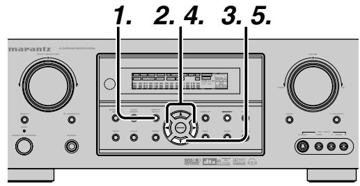
- Press the SIMPLE SETUP button on the unit to enter the "SPEAKERS" menu.
- Press or cursor button to select the speaker number.
- Press the cursor button to enter the "ROOM" menu.
- Press or cursor button to select the room size.
- After finishing all setup, press the cursor button to exit the SIMPLE SETUP menu.
Note:
- All Simple Setup menu is reset when the speaker setting is changed with Speaker Setup menu.
| S SIMPLE | SETUP |
| 1.SPEAKERS | : ? |
| 2.ROOM | : ? |
| EXIT |
The relation of the speakers number and conctted speaker
| CHANNEL | Front L/R (F) | Front Center (C) | Surround L/R (S) | Surround Back L/R (SB) | Sub woofer (SW) |
| 7.1 ch | LARGE | SMALL | SMALL | 2ch | YES |
| 7.0 ch | LARGE | SMALL | SMALL | 2ch | NONE |
| 6.1 ch | LARGE | SMALL | SMALL | 1ch | YES |
| 6.0 ch | LARGE | SMALL | SMALL | 1ch | NONE |
| 5.1 ch | LARGE | SMALL | SMALL | NONE | YES |
| 5.0 ch | LARGE | SMALL | SMALL | NONE | NONE |
| 4.1 ch | LARGE | NONE | SMALL | NONE | YES |
| 4.0 ch | LARGE | NONE | SMALL | NONE | NONE |
| 3.1 ch | LARGE | SMALL | NONE | NONE | YES |
| 3.0 ch | LARGE | SMALL | NONE | NONE | NONE |
| 2.1 ch | LARGE | NONE | NONE | NONE | YES |
| 2.0 ch | LARGE | NONE | NONE | NONE | NONE |
The relation of the room size and floor space
| SIZE | Floor space | Width (W) | Depth (D) | Imaging Distance | |
| SMALL | 10 m² | 2.7 m | 3.6 m | Front (F) | 6 ft. (1.8 m) |
| Center (C) | 5 ft. (1.5 m) | ||||
| Surround (S) | 4 ft. (1.2 m) | ||||
| Surr. Back (SB) | 5 ft. (1.5 m) | ||||
| Sub Woofer (SW) | 5 ft. (1.5 m) | ||||
| MEDIUM | 16 m² | 3.6 m | 4.5 m | Front (F) | 7 ft. (2.1 m) |
| Center (C) | 6 ft. (1.8 m) | ||||
| Surround (S) | 5 ft. (1.5 m) | ||||
| Surr. Back (SB) | 7 ft. (2.1 m) | ||||
| Sub Woofer (SW) | 6 ft. (1.8 m) | ||||
| LARGE | 24 m² | 4.5 m | 5.4 m | Front (F) | 9 ft. (2.7 m) |
| Center (C) | 8 ft. (2.4 m) | ||||
| Surround (S) | 7 ft. (2.1 m) | ||||
| Surr. Back (SB) | 8 ft. (2.4 m) | ||||
| Sub Woofer (SW) | 8 ft. (2.4 m) | ||||
The relation of the room size and floor space is a roughly standard.
BASIC OPERATION
(PLAY BACK)
SELECTING AN INPUT SOURCE
Before you can listen to any input media, you must first select the input source on the SR5500.
Example : DVD
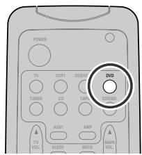
To select DVD, turn the INPUT FUNCTION SELECTOR knob on the front panel or simply press the DVD button on the remote.
After you have selected DVD, simply turn on the DVD player and play the DVD.
- As the input source is changed, the new input name will appear momentarily an OSD information on the video display. The input name will also appear in the display, on the front-panel.
- As the input is changed, the SR5500 will automatically switch to the digital input, surround mode, attenuation, and night mode status which were entered during the configuration process for that source.
- When an audio source is selected, the last video input used remains routed to the VCR1 & DSS/ VCR2 Outputs and Monitor Output. This permits simultaneous viewing and listening to different sources.
- When a Video source is selected, the video signal for that input will be routed to the Monitor Output jacks and will be viewable on a TV monitor connected to the SR5500. If a component video input is connected to the DVD or DSS component inputs, it will be routed to the Component Video Output. Make certain that your TV is set to the proper input to view the signal.
VIDEO CONVERT
When this function is activated, the video or S-video signal can be emitted from the video, S-video or component video output terminal.
To activate this function, select VIDEO CONVERT in PREFERENCE menu and set ENABLE.
Notes:
- The component video signal is emitted only from component video output terminal.
When the video equipment is connected by component terminal, connect the monitor and SR5500 by the component terminal. - This function is unavailable for the REC out terminal.
- This function is unavailable for the still picture, fast forward and reverse playing of the video component.
- If, while attempting to use the video convert feature, the SR5500 cannot synchronize with the display device, "NO SIGNAL" appears on the monitor, or noise is generated, this feature cannot be used. All of these signs are caused by equipment incompatibility; there is nothing wrong with the SR5500.
In such case, set VIDEO CONVERT in the PREFERENCE menu to DISABLE. Also, connect the video input signal to the display device via the MONITOR OUT terminal under VIDEO and the S-video input signal to the display device via the MONITOR OUT terminal under S-VIDEO.
Example:
Monitor is connected with the component.
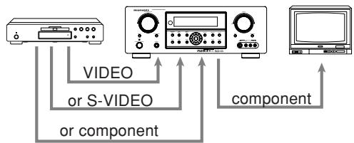
Monitor is connected with the video or S-video.
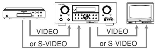
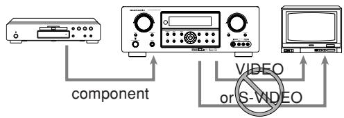
The signal cannot be converted from the component to the video or S-video.
Notes of OSD menu:
- The setup menu can be displayed through all video out (COMPONENT, S-VIDEO, VIDEO).
- The setting informations (e.g. volume setting) are displayed through all video out when theVIDEO CONVERT function are set ENABLE.
Note:
No setting information is displayed when the signal is emitted from the COMPONENT IN to COMPONENT OUT.
- The setting informations (e.g. volume setting) are displayed through the S-VIDEO or VIDEO out when the VIDEO CONVERT function are set DISABLE. When the S-VIDEO and VIDEO outputs are used simultaneously, the setting informations are displayed through the S-VIDEO out only.
To select the surround mode during playback, press the SURROUND MODE button on the front panel or the Surround mode buttons on the remote.
ADJUSTING THE MAIN VOLUME

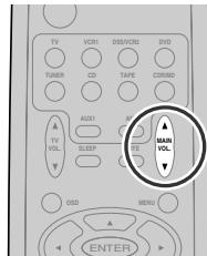
ENGLISH
Adjust the volume to a comfortable level using the VOLUME control knob on the front panel or VOL ▲
/▼ buttons on the remote.
To increase the volume, turn the VOLUME knob clockwise or press VOL button on the remote, to decrease the volume, turn counterclockwise or press VOL button on the remote.
Notes:
- The volume can be adjusted within the range of - to 18dB , in steps of 1dB .
However, when the channel level is set as described on page 19, if the volume for any channel is set at +1dB or greater, the volume cannot be adjusted up to 18dB .
(In this case the maximum volume adjustment range is "18 dB - Maximum value of channel level)
ADJUSTING THE TONE (BASS & TREBLE) CONTROL
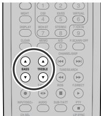
During a listening session you may wish to adjust the Bass and Treble Control to suit your listening tastes or room acoustics.
(Using the remote control unit)
To adjust the bass effect, press BASSA or BASSV on the remote.
To adjust the treble effect, press TREBLE▲ or TREBLE▼ on the remote.
Note:
- The tone control function can work in the AUTO Surround, Stereo, Dolby PLIIx, DTS, DTS-ES, and Multi Ch. Stereo mode.
HSITONE
TEMPORARILY TURNING OFF THE SOUND
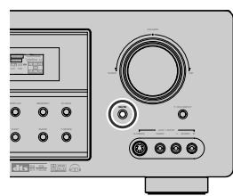
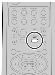
To temporarily silence all speaker outputs such as when interrupted by a phone call, press the MUTE button on the front panel or MUTE button on the remote.
This will interrupt the output to all speakers and the head-phone jack, but it will not affect any recording or dubbing that may be in progress.
When the system is muted, the display will show "MUTE".
Press the MUTE button again to return to normal operation.
USING THE SLEEP TIMER
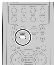
To program the SR5500 for automatic standby, press the SLEEP button on the remote. Each press of the button will increase the time before shut down in the following sequence.

The sleep time will be shown for a few seconds in the display on the front panel, and it will count down until the time has elapsed.
When the programmed sleep time has elapsed, the unit will automatically turn off.
Note that the SLEEP indicator on the display will illuminate when the Sleep function is programmed.
To cancel the Sleep function, press the SLEEP button until the display shows "SLEEP OFF" and the SLEEP indicator will disappear.
NIGHT MODE
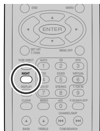
Press the NIGHT button on the remote to turn on the NIGHT mode.
Selecting the Night Mode ON is effective in Dolby Digital only, and it compresses the dynamic range. This softens loud passages such as sudden explosions, to help prevent disturbing others late at night.
To turn off the Night mode, press the NIGHT button again.
SURROUND MODE
The SR5500 is equipped with many surround modes. These are provided to reproduce a variety of surround sound effects, according to the content of the source to be played.
The available surround modes may be restricted depending on the input signal and speaker setup.
AUTO
When this mode is selected, the receiver determines whether the digital input signal is Dolby Digital, Dolby Digital Surround EX, DTS, DTS-ES, DTS 96/24 or PCM-audio.
Surround EX & DTS-ES will operate for multichannel source that has a Dolby Digital Surround EX or DTS-ES auto trigger flag in the digital signal.
When a Dolby Digital or DTS signal is input, the number of channels for which the corresponding signal is encoded will be played.
Inputting a Dolby Digital two channel signal with Dolby surround status automatically subjects that signal to Pro Logic IIx movie processing before play.
PCM 96 kHz source material can be played in this mode.
Notes:
- When you use this mode with certain DVD and CD players, performing operations such as "Skip" or "Stop" may momentarily interrupt the output.
- When the signal is not decoded, the mode is changed to AUTO mode automatically. Refer to page 23 to confirm the available decoding mode.
MODE
(Dolby Digital, Pro Logic IIx MOVIE, Pro Logic IIx MUSIC, Pro Logic IIx GAME, Pro Logic)
This mode is used with source materials encoded in Dolby Digital and Dolby Surround.
DOLBY DIGITAL
This mode is enabled when playing source materials encoded in Dolby Digital.
Playing multichannel encoded 6.1 or 7.1-channel Dolby Digital sources provides five main audio channels (left, center, right, surround left and surround right) and Low Frequency Effect channel. Dolby Digital EX decoding is not available in this mode.
Dolby Pro Logic IIx brings the excitement of surround sound to any stereo mix, while making existing Dolby Surround mixes sound more like discrete 7.1 channels Surround sound.
Dolby Pro Logic IIx has 3 modes. Please see below.
Pro Logic IIx MOVIE
This mode provides 6.1 or 7.1 channel surround sound from Dolby Surround encoded stereo movie sound tracks.
Pro Logic IIx MUSIC
This mode provides 6.1 or 7.1 channel surround sound from conventional stereo sources, analog or digital, such as CD, Tape, FM, TV, Stereo VCR, etc.
Pro Logic IIx GAME
Game mode restores the impact low-frequency surround effects by routing them to the system's subwoofer.
Pro Logic
This mode emulated original Dolby Pro Logic decoding (3/1 surround) suit for Dolby Surround encoded stereo movie soundtracks.
Notes:
- Pro Logic IIx mode will decode as Pro Logic II mode when the SURROUND BACK SPEAKER is set NONE in SPEAKER SETUP menu. (See SPEAKER SETUP, page 18)
- Pro Logic IIx mode is available for a 2ch input signal which is encoded in Dolby Digital or PCM format.
- PCM-audio signals can be subjected to Pro Logic processing when the sampling frequency is 32 kHz, 44.1 kHz or 48 kHz.
EX/ES
This mode provides 6.1 channel surround for DOLBY DIGITAL EX, DTS-ES encoded source material such as DVD.
This mode cannot be used when an analog input has been selected.
Dolby Digital EX
In a movie theater, film soundtracks that have been encoded with Dolby Digital surround EX technology are able to reproduce an extra channel which has been added during the mixing of the program.
This channel, called Surround Back, places sounds behind the listener in addition to the currently available front left, front center, front right, surround right, surround left and subwoofer channels.
This additional channel provides the opportunity for more detailed imaging behind the listener and brings more depth, spacious ambience and sound localization than ever before.
Dolby Digital EX is not available in the system without surround back speaker(s).
DTS-ES (Discrete 6.1, Matrix 6.1)
DTS-ES adds the surround center channel audio to the DTS 5.1-channel format to improve the acoustic positioning and makes acoustic image movement more natural with the 6.1-channel reproduction.
This receiver incorporates a DTS-ES decoder, which can handle DTS-ES Discrete-encoded and DTS-ES Matrix-encoded program sources from DVD, etc..
DTS-ES Discrete 6.1 features digital discrete recording of all channels including the surround back channel(s) and higher quality of audio reproduction.
DTS-ES is not available in the system without a surround back speaker.
dtsmODE
(dts, Neo:6 Cinema, Neo:6 Music)
This mode is for DTS encoded source materials such as LASER DISC, CD, and DVD. Neo:6 is for some 2 channel sources.
dts : This mode is enabled when playing source materials encoded in dts multichannel.
Playing multichannel encoded 5.1-channel dts sources provides five main audio channels (left, center, right, surround left and surround right) and Low Frequency Effect channel.
dts-ES decoding is not available in this mode.
The DTS mode cannot be used when an analog input has been selected.
This mode decodes 2-channel signals into 6-channel signals using high-accuracy digital matrix technology.
The DTS NEO:6 decoder has near-discrete properties in the frequency characteristics of the channels as well as in channel separation.
According to the signals to be played back, DTS NEO:6 uses either the NEO:6 CINEMA mode optimized for movie playback or the NEO:6 MUSIC mode optimized for music playback.
Notes:
- Neo:6 mode is available to 2ch input signals which are encoded in Dolby Digital or PCM format.
- PCM-audio signals can be subjected to Pro Logic processing when the sampling frequency is 32 kHz, 44.1 kHz or 48 kHz.
MULTICH.ST
This mode is used to create a wider, deeper and more natural soundstage from two channel source material. This is done by feeding the left channel signal to both left front and left surround speaker and the right channel signal to both right front and right surround speaker. Additionally, the center channel reproduces a mix of the right and left channel.
CIRCLE SURROUND II
(CSII-CINEMA, CSII-MUSIC, CSII-MONO)
Circle Surround is designed to enable multichannel surround sound playback of non-encoded and multichannel encoded material.
Backward compatibility provides listeners with up to 6.1 channels of surround performance from entire collection of music and film, including broadcast, videotape and stereo recorded music.
Depending on source material, you can select CSII-Cinema mode, CSII-Music mode or CSII-Mono mode.
Notes:
- CS II mode is available for 2ch input signals which are encoded in Dolby Digital or PCM format.
- PCM-audio signals can be subjected to Pro Logic processing when the sampling frequency is 32 kHz, 44.1 kHz or 48 kHz.
VIRTUAL
This mode creates a virtualized surround sound experience from a two-speaker (front L and R) playback system playing any multichannel audio source (such as found on DVDs and digital broadcasts), including Dolby Digital, Dolby Pro Logic or DTS.
STEREO
This mode bypasses all surround processing. In stereo program sources, the left and right channels play normally when PCM-audio or analog stereo is input.
With Dolby Digital and DTS sources, the 5.1 multichannels are converted to two channel stereo. 96kHz PCM source material can be played back in stereo mode.
PURE-DIRECT
In the pure direct mode, the tone control circuit and bass management configuration are bypassed for full range frequency response and the purist audio reproduction.
96 kHz PCM source material can be played back in this mode.
Notes:
- Internal speaker size is setup to front L / R = LARGE, Center = LARGE, Surround L / R = LARGE and Subwoofer = YES automatically. Tone controls and additional processing are also defeated.
- When you use this mode with certain DVD and CD players, performing operations such as "Skip" or "Stop" may momentarily interrupt the output.
CAUTION
NOTE for DTS signal
- Connected DVD-player, laser-disc player or CD-player needs to support DTS-digital output. You may not be able to play some DTS source signals from certain CD players and LD players even if you connect the player to the SR5500 digitally. This is because the digital signal has been processed (such as the output level, sampling frequency, or frequency response) and the SR5500 cannot recognize the signal as DTS data.
- Depending on the player used, DTS play may produce a short noise. This is not a malfunction.
- While signals from DTS-laser disc or CD are playing in another Surround mode, you cannot switch to digital input or from digital input to analog input by INPUT SETUP in SETUP MAIN MENU or the A/D button.
- The outputs for the VCR 1 OUT, DSS/VCR 2 OUT, TAPE OUT, and CD-R OUT output analog audio signals. Do not record from CDs or LDs that support DTS using these outputs. If you do, the DTS-encoded signal will be recorded as noise.
NOTE for Dolby Digital Surround EX signal
- When playing Dolby Digital Surround EX-encoded software in 6.1 channels, it is required to set the EX/ES mode.
- Note that some of Dolby Digital Surround EX-encoded software does not contain the identification signal. In this case, set the EX/ES mode manually.
NOTE for 96kHz PCM audio
- AUTO, PURE-DIRECT, and STEREO modes can be used when playing PCM signals with a sampling frequency of 96kHz (such as from DVD-Video discs that contain 24 bit, 96kHz audio). If such signals are input during playback in one of the other surround modes, output from SR5500 will be muted.
- Certain DVD player models inhibit digital output. For details, refer to the player's operation manual.
- Some DVD formatted discs feature copy protection. When using such disc, 96 kHz PCM signal is not output from the DVD player. For details, refer to the player's operation manual.
The relation between the selected surround mode and the input signal
The surround mode is selected with the surround mode selector on SR5500 or the remote control unit. However, the sound you hear is subject to the relationship between the selected surround mode and input signal. That relationship is as follows;
| Surround Mode | Input Signal | Decoding | Output Channel | Front information display | |||||
| L/R | C | SLSR | SBSR | SubW | Signal format indicators | Channel status | |||
| AUTO | Dolby Surr. EX | Dolby Digital EX | O | O | O | O | O | DIGITAL | L, C, R, SL, SR, S, LFE |
| Dolby D (5.1ch) | Dolby Digital 5.1 | O | O | O | - | O | DIGITAL | L, C, R, SL, SR, LFE | |
| Dolby D(2ch) | Dolby Digital 2.0 | O | - | - | - | - | DIGITAL | L, R | |
| Dolby D (2ch Surr) | Pro Logic IIx movie | O | O | O | O | - | DIGITAL , SURROUND | L, R, S | |
| DTS-ES | DTS-ES | O | O | O | O | O | dts, ES | L, C, R, SL, SR, S, LFE | |
| DTS 96/24 | DTS 96/24 | O | O | O | - | O | dts 96/24 | L, C, R, SL, SR, LFE | |
| DTS (5.1ch) | DTS 5.1 | O | O | O | - | O | dts | L, C, R, SL, SR, LFE | |
| PCM/Audio) | PCM (Stereo) | O | - | - | - | - | PCM | L, R | |
| PCM 96kHz | PCM (96kHz Stereo) | O | - | - | - | - | PCM | L, R | |
| Analog | Stereo | O | - | - | - | - | ANALOG | - | |
| PURE DIRECT | Dolby D Surr. EX | Dolby Digital EX | O | O | O | O | O | DIGITAL | L, C, R, SL, SR, S, LFE |
| Dolby D (5.1ch) | Dolby Digital 5.1 | O | O | O | - | O | DIGITAL | L, C, R, SL, SR, LFE | |
| Dolby D (2ch) | Dolby Digital 2.0 | O | - | - | - | - | DIGITAL | L, R | |
| Dolby D (2ch Surr) | Pro Logic IIx movie | O | O | O | O | - | DIGITAL , SURROUND | L, R, S | |
| DTS-ES | DTS-ES | O | O | O | O | O | dts, ES DS | L, C, R, SL, SR, S, LFE | |
| DTS 96/24 | DTS 96/24 | O | O | O | - | O | dts 96/24 | L, C, R, SL, SR, LFE | |
| DTS (5.1ch) | DTS 5.1 | O | O | O | - | O | dtds | L, C, R, SL, SR, LFE | |
| PCM (Audio) | PCM (Stereo) | O | - | - | - | - | PCM | L, R | |
| PCM 96kHz | PCM (96kHz Stereo) | O | - | - | - | - | PCM | L, R | |
| Analog | Stereo | O | - | - | - | - | ANALOG | - | |
| EX/ES | Dolby D Surr. EX | Dolby Digital EX | O | O | O | O | O | DIGITAL | L, C, R, SL, SR, S, LFE |
| Dolby D (5.1ch) | Dolby Digital EX | O | O | O | O | O | DIGITAL | L, C, R, SL, SR, LFE | |
| DTS-ES | DTS-ES | O | O | O | O | O | dts, ES | L, C, R, SL, SR, S, LFE | |
| DTS(5.1ch) | DTS-ES | O | O | O | O | O | dtds | L, C, R, SL, SR, LFE | |
| DOLBY (PL Ixx movie) (PL Ixx music) (PL Ixx game) (Pro Logic) | Dolby D Surr. EX | Dolby Digital 5.1 | O | O | O | O | O | DIGITAL | L, C, R, SL, SR, S, LFE |
| Dolby D (5.1ch) | Dolby Digital 5.1 | O | O | O | O | O | DIGITAL | L, C, R, SL, SR, LFE | |
| Dolby D (2ch) | Pro Logic IIx | O | O | O | O | - | DIGITAL | L, R | |
| Dolby D (2ch Surr) | Pro Logic IIx | O | O | O | O | - | DIGITAL , SURROUND | L, R, S | |
| PCM (Audio) | Pro Logic IIx | O | O | O | O | - | PCM | L, R | |
| Analog | Pro Logic IIx | O | O | O | O | - | ANALOG | - | |
| DTS (Neo:6 Cinema) (Neo:6 Music) | DTS-ES | DTS 5.1 | O | O | O | - | O | dtds, ES | L, C, R, SL, SR, S, LFE |
| DTS 96/24 | DTS 96/24 | O | O | O | - | O | dtds 96/24 | L, C, R, SL, SR, LFE | |
| DTS (5.1ch) | DTS 5.1 | O | O | O | - | O | dtds | L, C, R, SL, SR, LFE | |
| PCM (Audio) | Neo:6 | O | O | O | O | - | PCM | L, R | |
| Analog | Neo:6 | O | O | O | O | - | ANALOG | - | |
| Dolby D (2ch) | Neo:6 | O | O | O | O | - | DIGITAL | L, R | |
| Dolby D (2ch Surr) | Neo:6 | O | O | O | O | - | DIGITAL , SURROUND | L, R, S | |
| CS II Cinema CS II Music CS II Mono | PCM (Audio) | CS II | O | O | O | O | O | PCM | L, R |
| Analog | CS II | O | O | O | O | O | ANALOG | - | |
| Dolby D (2ch) | CS II | O | O | O | O | O | DIGITAL | L, R | |
| Dolby D (2ch Surr) | CS II | O | O | O | O | O | DIGITAL , SURROUND | L, R, S | |
| STEREO | Dolby Surr. EX | Stereo | O | - | - | - | O | DIGITAL | L, C, R, SL, SR, S, LFE |
| Dolby D (5.1ch) | Stereo | O | - | - | - | O | DIGITAL | L, C, R, SL, SR, LFE | |
| Dolby D (2ch) | Stereo | O | - | - | - | - | DIGITAL | L, R | |
| Dolby D (2ch Surr) | Stereo | O | - | - | - | - | DIGITAL , SURROUND | L, R, S | |
| DTS-ES | Stereo | O | - | - | - | O | dtds, ES | L, C, R, SL, SR, S, LFE | |
| DTS 96/24 | Stereo | O | - | - | - | O | dtds 96/24 | L, C, R, SL, SR, LFE | |
| DTS (5.1ch) | Stereo | O | - | - | - | O | dtds | L, C, R, SL, SR, LFE | |
| PCM (Audio) | Stereo | O | - | - | - | - | PCM | L, R | |
| PCM 96kHz | Stereo | O | - | - | - | - | PCM | L, R | |
| Analog | Stereo | O | - | - | - | - | ANALOG | - | |
| Virtual | Dolby Surr. EX | Virtual | O | - | - | - | - | DIGITAL | L, C, R, SL, SR, S, LFE |
| Dolby D (5.1ch) | Virtual | O | - | - | - | - | DIGITAL | L, C, R, SL, SR, LFE | |
| Dolby D (2ch) | Virtual | O | - | - | - | - | DIGITAL | L, R | |
| Dolby D (2ch Surr) | Virtual | O | - | - | - | - | DIGITAL , SURROUND | L, R, S | |
| DTS-ES | Virtual | O | - | - | - | - | dtds, ES | L, C, R, SL, SR, S, LFE | |
| DTS (5.1ch) | Virtual | O | - | - | - | - | dtds | L, C, R, SL, SR, LFE | |
| PCM (Audio) | Virtual | O | - | - | - | - | PCM | L, R | |
| Analog | Virtual | O | - | - | - | - | ANALOG | - | |
| Multi Ch. Stereo | Dolby Surr. EX | Dolby Digital EX | O | O | O | O | O | DIGITAL | L, C, R, SL, SR, S, LFE |
| Dolby D (5.1ch) | Dolby Digital 5.1 | O | O | O | - | O | DIGITAL | L, C, R, SL, SR, LFE | |
| Dolby D (2ch) | Multi Channel Stereo | O | O | O | O | - | DIGITAL | L, R | |
| Dolby D (2ch Surr) | Multi Channel Stereo | O | O | O | O | - | DIGITAL , SURROUND | L, R, S | |
| DTS-ES | DTS-ES | O | O | O | O | - | dtds, ES | L, C, R, SL, SR, S, LFE | |
| DTS (5.1ch) | DTS 5.1 | O | O | O | - | O | dtds | L, C, R, SL, SR, LFE | |
| PCM (Audio) | Multi Channel Stereo | O | O | O | O | - | PCM | L, R | |
| Analog | Multi Channel Stereo | O | O | O | O | - | ANALOG | - | |
Notes:
- Dolby Digital (2 ch: Lt/Rt): signal with Dolby Surround flag Speakers are full set.
- No sound outputs from the surround speaker, center speaker and subwoofer if the DVD disc has no surround data.
Abbreviations
L/R:Front speakers
C:Center speaker
SL/SR : Surround speakers
SBL/SBR : Surround Back speakers
SubW: Sub woofer speaker
OTHER FUNCTION
TV AUTO ON/OFF FUNCTION
This function allows the component connected to the TV-VIDEO in jack to control the power (ON/OFF) to the SR5500.
AUTO POWER ON
- Be sure the TV auto mode is ENABLED. (Refer page 19: System Setup)
- Connect your TV TUNER (etc) to the TVVIDEO in terminal. Be sure to connect theVIDEO input.
- Turn OFF the power to the TV TUNER and the SR5500.
- Turn ON the TV TUNER and tune in a receivable station.
- When the station is received, the SR5500 turns ON and TV is selected automatically.
AUTO POWER OFF
- In the above situation, turn the TV TUNER OFF or select a channel that does not contain any broadcast.
- The power to the SR5500 switches to STANDBY after approx. 5 minutes.
Notes:
- AUTO POWER OFF is canceled if the SR5500 is set to a source other than TV. The function reactivates when TV is selected again.
- Some TV broadcasts may cause the TV AUTO FUNCTION to turn ON.
- The S-Video terminal does not support "TV AUTO ON/OFF" function.
ATTENUATION TO ANALOG INPUT SIGNAL
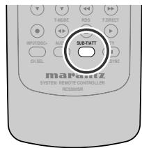
If the selected analog audio input signal is greater than the capable level of internal processing, the "PEAK" indicator will light up on the front display. If this happens, you should press the ATT button on the remote.
"ATT" indicator will be illuminated when this function is activated. The signal-input level is reduced by about half. Attenuation will not work with the output signal of TAPE-OUT, CD-R/MD-OUT, VCR1-OUT and DSS/VCR2-OUT.
This function is memorized for each individual input source.
LISTENING THROUGH HEADPHONES
This jack may be used to listen to the SR5500's output through a pair of headphones. Be certain that the headphones have a standard 1/4" stereo phono plug. (Note that the speakers will automatically be turned off when the headphone jack is in use.)
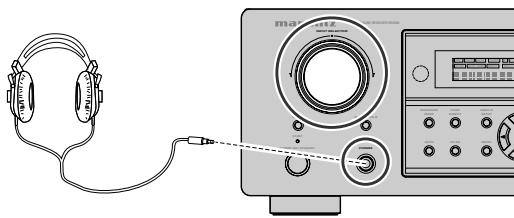
Note:
- The surround mode returns to the previous setting as soon as the plug is removed from the jack.
DOLBY HEADPHONE MODE
This feature simulates the waveforms of the actual sounds heard from the speakers.
When headphones are used, the MENU button automatically switches to the Dolby headphone mode.
The OSD that appears when the MENU button is pressed is shown below.
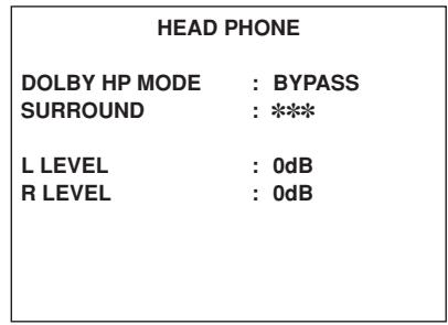
DOLDBY HP (Headphone) MODE can be selected with the left and right cursor buttons.
BYPASS: Bypasses the Dolby headphone mode and delivers ordinary 2-channel stereo.
DH1: The size of a typical living room space is simulated.
DH2: The expansiveness of a structure as large as a music hall is simulated.
DH3: A large space such as that found in a movie theater is simulated.
When the PURE DIRECT mode is selected, Dolby surround processing is bypassed and *** is displayed as the mode indication.
L/R LEVEL can be set in the ± 10 dB range.
Notes:
- The surround mode returns to the previous setting as soon as the plug is removed from the jack.
TONE cannot be set when any of the modes in DH1, DH2, or DH3 is selected. - The Dolby Headphone function will not work when 32 or 96kHz PCM digital signals are input.
VIDEO ON/OFF
When no video signal is connected to the SR5500 or a DVD, etc., is connected directly to your TV, the unnecessary video circuit can be turned off by selecting the "VIDEO OFF" setting.
To select video off, press the AMP button and press the V-OFF button.
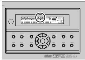
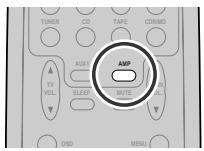
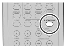
DISPLAY MODE
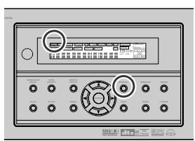
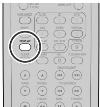
You can select the display mode for the front display of the SR5500.
To select this mode, press the DISPLAY on the remote control.
When this button is pressed, the display mode is switched in the following sequence.
Surround Mode Auto-display Off Display Off Input Function Surround Mode....
In Auto display off mode, the display is off. But, if you make a change to the unit such as input or surround mode, the display will show that change, then go back to off after about 3 seconds. When changing the volume, it is not displayed.
In Display off mode, the display is off completely.
Note:
- Only the DISP indicator will be illuminated on the front display in display off condition
HSITONE
SELECTING ANALOG AUDIO INPUT OR DIGITAL AUDIO INPUT
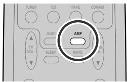
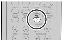
If you have already assigned the digital inputs, you can temporarily select the audio input mode for each input source as following procedures.
Press the AMP button and press the A/D (0) button.
When this button is pressed, the input mode is switched in the following sequence.
Digital Auto Digital Analog Digital Auto....
In Digital Auto mode, the types of signals being input to the digital and analog input jacks for the selected input source are detected automatically.
If no digital signal is being input, the analog input jacks are selected automatically.
In Digital mode, input is fixed to an assigned digital input terminal.
In analog mode, the analog input jacks are selected.
This selecting is temporary, so the result will not be stored in memory.
If you need to change the input mode completely, use INPUT SETUP in OSD menu system. (see page 18)
RECORDING AN ANALOG SOURCE
In normal operation, the audio or video source selected for listening through the SR5500 is sent to the record outputs.
This means that any program you are watching or listening to may be recorded simply by placing machines connected to the outputs for TAPE OUT, CD-R/MD OUT, VCR1 OUT, and DSS/VCR2 OUT in the record mode.
To record the input source signal you are currently watching or listening to
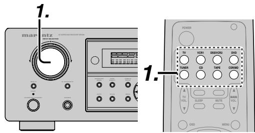
- Select the input source to record by turning the INPUT FUNCTION SELECTOR knob on the front panel or simply press the input selector buttons on the remote.
The input source is now selected and you may watch or listen to it as desired.
- The currently selected input source signal is output to the TAPE OUT, CD-R/MD OUT, VCR1 OUT, and DSS/VCR2 OUT outputs for recording.
- Start recording to the recording component as desired.
Recording the video from one source and the audio from another
You can add the sound from one source to the video of another source to make your own video recordings.
Below is an example of recording the sound from a compact disc player connected to CD IN and the video from a video camera connected to VCR1 to video cassette recorder connected to the DSS/ VCR2 OUT jack.
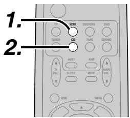
- Switch the video output source to VCR1 by simply pressing the input selector buttons on the remote.
- Switch the audio input source to CD by simply pressing the input selector buttons on the remote.
- Now "CD" has been selected as the audio input source and "VCR1" as the video input source.
Notes:
- If you change the input source during recording, you will record the signals from the newly selected input source.
- You cannot record the surround effects.
- Digital input signals are only output to the digital outputs. There is no conversion from digital to analog.
When connecting CD players and other digital components, do not connect only the digital terminals, but the analog ones as well.
HT-EQ
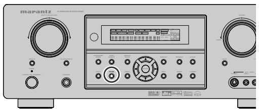
Press the HT-EQ button on the front panel to turn on the HT-EQ mode.
The tonal balance of a film soundtrack will be excessively bright and harsh when played back over audio equipment in the home. This is because film soundtracks were designed to be played back in large movie theater environments.
Activating the HT-EOQ feature when watching a film made for movie theaters corrects this and restores the correct tonal balance.
The HT-EQ feature is available except in the following modes.
- 7.1 CH INPUT
- PURE-DIRECT
- When VIRTUAL is set for the surround mode
7.1 CH INPUT
The SR5500 is equipped for future expansion through the use of Multi channel SACD multichannel player or DVD-Audio player.
When this is selected, the input signals connected to the L(front left), R (front right), CENTER, SL (surround left), SR (surround right) and SBL (surround back left) and SBR (surround back right) channels of the 7.1 CH. In jacks are output directly to the front (left and right), center, surround (left and right) and surround back speaker systems as well as the pre-out jacks without passing through the surround circuitry.
In addition, the signal input to the SW (subwoofer) jack is output to the PRE OUT SW (subwoofer) jack.
When 7.1 CH. INPUT is selected, the last video input used remains routed to the Monitor Outputs. This permits simultaneous viewing with video sources
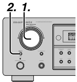
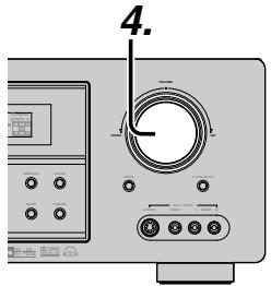
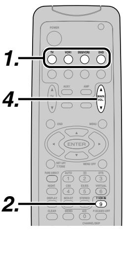
- Select a desired Video source to decide the routed video signal to the Monitor Outputs .
- Press the 7.1 CH INPUT button on the front panel or press 7.1 CH IN on the remote to switch the 7.1 channel input.
- If it is necessary to adjust the output level of each channel, press the CH.SEL button on the remote.
Adjust the speaker output levels so that you can hear the same sound level from each speaker at the listening position. For the front left, front right, center, surround left, surround right and surround back speakers, the output levels can be adjusted between -10 to +10 dB. The subwoofer can be adjusted between -15 and +10 dB.
These adjustments result will be stored to 7.1 CH. INPUT memory.
- Adjust the main volume with the MAIN VOLUME knob or the VOL buttons on the remote.
To cancel the 7.1 CH. INPUT setting, press the 7.1 CH INPUT button on the front panel or press 7.1 CH IN on the remote.
Notes:
- When the 7.1 CH. Input is in use, you may not select a surround mode, as the external decoder determines processing.
- In addition, there is no signal at the record outputs when the 7.1 CH. Input is in use.
AUX2 INPUT
If you don't need to connect 7.1 Ch. input terminals with multi channel decoder,
L(front left) and R (front right) inputs terminals are available as AUX2 input.
In this case, You can connect additional audio source to AUX2 as other audio input terminals.
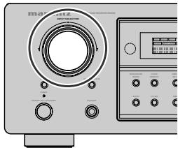
LIP.SYNC
Depending on the image device (TV, monitor, projector, etc.) connected to the SR5500, a time lag can occur between image signal processing and audio signal processing. Though minor, this time lag can interfere with movie and music enjoyment. The LIP.SYNC feature delays the audio signal with respect to the image signal output from the SR5500 to correct the time lag between the sound and image. It can be operated with the "LIP.SYNC" and and cursor buttons of the remote controller. Set the remote controller to the AMP mode before operating the LIP.SYNC feature. The initial setting is OFF (0 ms).The time lag can be adjusted in 10 ms steps up to 200 ms. Watch the picture on the image device (i.e., TV, monitor, projector, etc.) as you adjust the time lag.
Note:
- The LIP.SYSNC feature turns OFF (0 ms) in the PURE DIRECT mode. When the PURE DIRECT mode is deactivated, the set value of the LIP.SYSNC feature is automatically restored.
Frequency scan step for AM is selectable. Default setup is 10kHz step, if your country's standard is 9kHz step, Press TUNER button on the remote more than 6 seconds. Scan step will change.
Note:
- Preset memory for the tuner will clear by changing this setup.
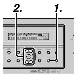
AUTO TUNING
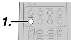
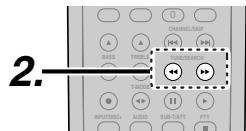
(Using the SR5500)
- To select tuner and desired band (FM or AM), press the BAND button on the front panel.
- Press the or cursor buttons on the front panel for more than 1 second to start the auto tuning function.
- Automatic searching begins then stops when a station is tuned in.
(Using the remote control unit)
- To select tuner and desired band (FM or AM), press the TUNER button twice within in two seconds on the remote.
- Press the or for more than 1 second on the remote.
- Automatic searching begins then stops when a station is tuned in.
If tuning does not stop at the desired station, use to the "Manual tuning" operation.
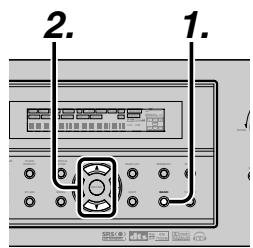
MANUAL TUNING
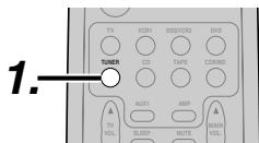
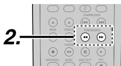
HSIN
(Using the SR5500)
- To select tuner and desired band (FM or AM), press the BAND button on the front panel
- Press the or cursor buttons on the front panel to select the desired station.
(Using the remote control unit)
- To select tuner and desired band (FM or AM), press the TUNER button twice within in two seconds on the remote.
- Press the or on the remote to tune in the desired station.

DIRECT FREQUENCY CALL
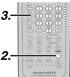
- To select tuner and desired band (FM or AM), press the TUNER button twice within two seconds on the remote.
- Press the F.DIRECT on the remote, display will show "FREQ----".
- Input your desired station's frequency with the numeric buttons on the remote.
- The desired station will automatically be tuned.
HSITON
(FM) TUNING MODE (AUTO STEREO OR MONO)
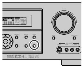
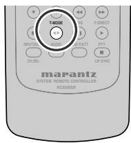
When in the auto stereo mode, AUTO indicator will be illuminated on the display.
The "ST" indicator is illuminated when a stereo broadcast is tuned in.
At open frequencies, the noise is muted and the "TUNED" and "ST" indicators are not illuminated.
If the signal is weak, it may be difficult to tune into the station in stereo. In such a case, press the T-MODE button on the front panel or remote.
"AUTO" indicator is not illuminated, if FM stereo broadcasts are received in monaural and the "ST" indicator is not illuminated.
To return to auto stereo mode, press the T-MODE button or press T-MODE button on the remote again. AUTO indicator is illuminated on the display.
PRESET MEMORY
With this unit you can preset up to 50 FM/AM stations in any order.
For each station, you can memorize the frequency and reception mode if desired.
AUTO PRESET MEMORY
This function automatically scans the FM and AM band and enters all stations with proper signal strength into the memory.
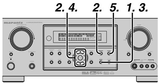
- To select FM, press the BAND button on the front panel.
- While pressing the MEMO button, press the cursor button.
"AUTO PRESET" will appear on the display, and scanning starts from the lowest frequency.
- Each time the tuner finds a station, scanning will pause and the station will be played for five seconds.
During this time, the following operations are possible.
The band can be changed by the BAND button.
4. If no button is pressed during this period, the current station is memorized in location Preset 02.
If you wish to skip the current station, press the cursor button during this period, this station is skipped and auto presetting continues.
5. Operation stops automatically when all 50 preset memory positions are filled or when auto scanning attains the highest end of all bands. If you desire to stop the auto preset memory at anytime, press the CLEAR button.
MANUAL PRESET MEMORY
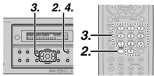
(Using the SR5500)
- Tune into the radio station you desire (Refer to the "MANUAL TUNING" or "AUTO TUNING" section).
- Press the MEMO button on the front panel. “- -” (preset number) starts blinking on the display.
- Select the preset number by pressing the or cursor buttons, while this is still blinking (approx. 5 seconds)
- Press the MEMO button again to enter. The display stops blinking.
The station is now stored in the specified preset memory location.
(Using the remote control unit)
- Tune into the radio station you desire (Refer to the "MANUAL TUNING" or "AUTO TUNING" section).
- Press the MEMO button on the remote. - - ^ 一 (preset number) starts blinking on the display.
- Enter the desired preset number by pressing the numeric buttons.
Note:
- When entering a single digit number (2 for example), either input "02" or just input "2" and wait for a few seconds.
RECALLING A PRESET STATION
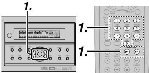
(Using the SR5500)
- Select the desired preset station by pressing the or cursor buttons on the front panel
(Using the remote control unit)
- Press the or buttons to select the desired preset station, or input your desired preset channel with the numeric buttons on the remote.
PRESET SCAN
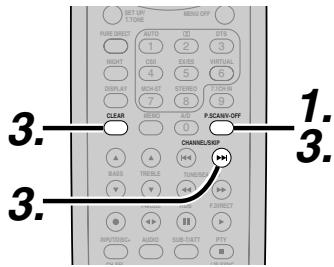
(Using the remote control unit)
- Press the P.SCAN on the remote.
"PRESET SCAN" appears on the display and then the preset station with the lowest preset number is recalled first.
- Preset stations are recalled in sequence (No.1 No.2 etc.) for 5 seconds each.
No stored preset number will be skipped.
- You can fast forward the preset stations by pressing the continuously.
When the desired preset station is received, cancel the preset scan operation by pressing the CLEAR button or P.SCAN on the remote.
CLEARING STORED PRESET STATIONS
You can remove preset stations from the memory using the following procedure.
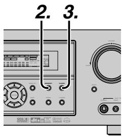
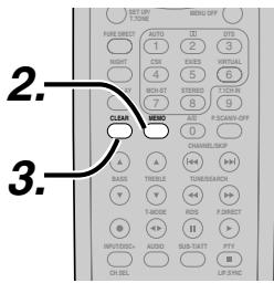
- Recall the preset number to be cleared with the method described in "Recalling" a preset station.
- Press the MEMO button on the front panel or press the MEMO button on the remote.
- The stored preset number blinks in the display for 5 seconds. While blinking, press the CLEAR button on the front panel or the remote.
- "xx CLEAR" appears on the display to indicate that the specified preset number has been cleared.
Note:
- To clear all stored preset stations, press and hold the CLEAR and the ENTER buttons for two seconds.
SORTING PRESET STATIONS
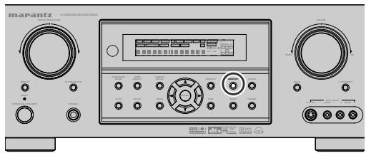
If you have stations memorized, and there is a gap in the sequential order:
I.e. the stations are stored as follows
(notice there is no stations programmed for presets for 4-9), you can have pre set 10 become pre set 5:
To sort the numbers, press and hold the MEMO and the cursor buttons.
"PRESET SORT" will appear on the display and sorting will be done.
NAME INPUT OF THE PRESET STATION.
This function allows the name of each preset channel to be entered using alphanumeric characters.
Before name inputting, you need to store preset stations with the preset memory operation.
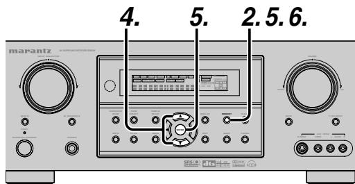
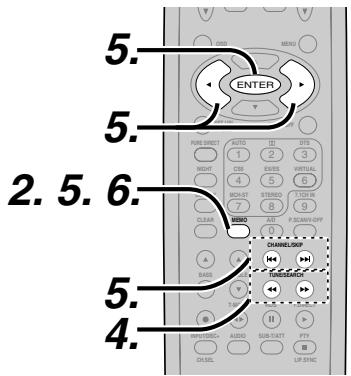
- Recall the preset number to be inputted name with the method described in "Recalling" a preset station.
- Press the MEMO button on the front panel or press the MEMO button on the remote for more than 3 seconds.
- The left most column of the station name indicator flashes, indicating the character entry ready status.
- When you press the or cursor buttons on the front panel or the / buttons on the remote, alphabetic and numeric characters will be displayed in the following order:
$$ \begin{array}{l} \mathsf {A} \rightarrow \mathsf {B} \rightarrow \mathsf {C} \dots \mathsf {Z} \rightarrow 1 \rightarrow 2 \rightarrow 3 \dots \dots \mathsf {0} \rightarrow - \rightarrow + \ \rightarrow / \rightarrow (\text {B l a n k}) \rightarrow \mathbf {A} \ \end{array} $$
$$ \begin{array}{l} \mathbf {U P} \rightarrow \ \leftarrow \text {D O W N} \ \end{array} $$
- After selecting the first character to be entered, press the MEMO or ENTER buttons, press the MEMO button on the remote.
The entry in this column is fixed and the next column starts to flash. Fill the next column the same way.
To move back and forth between the characters, press the / cursor buttons or press or buttons on the remote.
Note:
-
Unused columns should be filled by entering blanks.
-
To save the name, press the MEMO button on the front panel or remote for more than 2 seconds.
| Ten keypad | Press, press again, press again, etc. |
| 1 | A → B → C → 1 → A |
| 2 | D → E → F → 2 → D |
| 3 | G → H → I → 3 → G |
| 4 | J → K → L → 4 → J |
| 5 | M → N → O → 5 → M |
| 6 | P → Q → R → 6 → P |
| 7 | S → T → U → 7 → S |
| 8 | V → W → X → 8 → V |
| 9 | Y → Z → space → 9 → Y |
| 0 | → + → / → 0 |
HSITON
MULTI ROOM SYSTEM
The Multi Room system is a function which allows you to listen to the same or a different source in a room other than the room in which the SR5500 is located.
To use this function, a multi room remote unit and remote control signal receiver available from your Marantz dealer are necessary.
The operations possible with the multi room function are explained briefly below.
For details, refer to the instruction manual supplied with the multi room remote control unit and receiver.
When the outputs of the MULTI OUT terminals are wired and connected to amplifiers installed in other rooms or M (MULTI) SPEAKER B terminals are wired and connected to L&R speakers in other room, different sources can be played in rooms other than the main room in which this unit and the playback devices are installed.
SR5500 has some feature to MULTI ROOM SYSTEM as source selector, sleep timer, Multi Room Speaker output and remote control.
MULTI ROOM PLAYBACK USING THE MULTI ROOM OUT TERMINALS
The SR5500 is equipped with audio pre-out terminals for which the volume is adjustable as the MULTI output terminals.
A separately sold stereo power amplifier can be connected to enjoy multi room playback.
The MULTI OUT system can not be operated with the supplied remote controller.
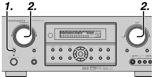
- Press the MULTI button. The unit enters multi room mode and the display indicates "SELECT SOURCE" and flashes the "MULTI" indicator for approx. 10 seconds.
- In this time, you can select the input source by turning the input selector knob.
Then, the display indicates "MULTI VOLUME" "MULTI VOL. xx" for approx. 5 seconds.
- During this time, you can set the volume level in the multi room as desired.
This will only set the volume in the second room.
MULTI ROOM PLAYBACK USING THE MULTI SPEAKER TERMINALS
The SR5500 allows you to connect another set of speakers and place them in a different room or separated area for listening to music.
The MULTI ROOM SPEAKER system can not be operated with the supplied remote controller.
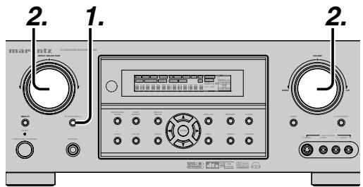
- Press the M. SPEAKER B button. The unit enters multi room speaker mode and the display indicates "SELECT SOURCE" and flashes the "MULTI" indicators for approx. 10 seconds.
- In this time, you can select the input source by turning the input selector knob.
- Then, the display indicates "MSPKR VOLUME" "MSPKR VOL.-18" for approx. 5 seconds.
During this time, you can set the volume level in the multi room as desired.
This will only set the volume in the multi room.
Notes for MULTI ROOM SPEAKER
- MULTI ROOM SPEAKER On/ Off is available in main room only.
- MULTI ROOM SPEAKER output terminals can be used when the SURROUND BACK SPEAKER is set NONE in SPEAKER SETUP menu. (See SPEAKER SETUP, page 18)
- "The Surr. Back Speakers are in use" is displayed by pressing the MULTI SPEAKER button when the SURROUND BACK SPEAKER is set except NONE in SPEAKER SETUP menu. (See SPEAKER SETUP, page 18)
- Multi room operations cannot be performed from the remote controller.
TROUBLESHOOTING
In case of trouble, check the following before calling for service:
- Are the connections made properly?
- Are you operating the unit properly following the user's guide?
- Are the power amplifiers and speaker working properly?
If the unit does not operate properly, check items shown in the following table.
If your trouble cannot be recovered with the remedy actions listed in the following table, malfunction of the internal circuitry is suspected; immediately unplug the power cable and contact your dealer, nearest Marantz authorized dealer or the Marantz Service Center in your country.
| SYMPTOM | CAUSE | REMEDY |
| SR5500 cannot be turned up. | The power plug is not connected. | Connect the power plug to the outlet. |
| No sound and picture are output even when power is on. | Mute is on. | Cancel mute using the remote control unit. |
| The input cable is not connected correctly. | See the connection diagram and connect the cables correctly. | |
| The master volume control is turned all the way down. | Adjust the master volume. | |
| The function selector position is wrong. | Select correct position. | |
| No speaker output. | The headphones are connected to theophone jack. | Disconnect the headphones. (Speakers will not output sound when headphones are connected.) |
| Incorrect Audio or Video for selected source. | Input cable connected incorrectly. | Connect the cable correctly by referring to the connection diagram. |
| Incorrect Audio from a channel. | Speaker cable connected incorrectly. | Connect the cable correctly by referring to the connection diagram. |
| No Audio output from the center channel speaker. | The center speaker cable connection is incomplete. | Connect the cable correctly. |
| STEREO has been selected for Surround mode. | When STEREO is selected for Surround mode, no sound will be output from the center speaker. Set another Surround mode. | |
| Center = NONE has been selected in SETUP mode. | Make the correct setting. | |
| No Audio output from the surround speakers. | The surround speaker cable connection is incomplete. | Connect the cable correctly. |
| STEREO has been selected for Surround mode. | When STEREO has been selected for Surround mode, no sound will be output from the surround speaker. Set another Surround mode. | |
| Surround = NONE has been selected in SETUP mode. | Make the correct setting. | |
| No Audio output from the surround back speakers. | The surround back speaker cable connection is incomplete. | Connect the cable correctly. |
| Surround mode is not EX/ES mode. | Set surround mode EX/ES. | |
| Surround back = NONE has been selected in SPEAKERS SIZE SETUP | Make the correct setting. |
| SYMPTOM | CAUSE | REMEDY |
| Can not select EX/ES mode. | Surround center=NONE has been selected in SPEAKERS SIZE SETUP | Make the correct setting. |
| Input signal is incompatible. | Use 5.1 channel source. | |
| Can not select Pro Logic IIx mode. | Input signal is incompatible. | Use 2 channel Dolby Digital input signal, PCM input signal or analog input signal. |
| Can not select Neo:6 mode. | Input signal is incompatible. | Use 2 channel Dolby Digital input signal, PCM input signal or analog input signal. |
| Can not select CSII mode. | Input signal is incompatible. | Use 2 channel Dolby Digital input signal, PCM input signal or analog input signal. |
| No output to Subwoofer Out. | Sub-woofer = NONE has been selected in SETUP mode. | Select Sub-woofer = YES. |
| Noise is produced during DTS-encoded CD or laser disc play. | Analog has been selected for input. | Be sure to perform digital connection, select digital input, then play. |
| A specific channel does not produce output. | Nothing recorded on source. | Check the encoded channel on the source side. |
| FM or AM reception fails. | Antenna connection is incomplete. | Correctly connect the indoor FM and AM antennas to FM and AM antenna outlets. |
| Noise is heard during AM reception. | Reception is affected by other electrical fields. | Try changing location where the AM indoor antenna is set up. |
| Noise is heard during FM reception. | The radio waves from the broadcasting station are weak. | Install an FM outdoor antenna. |
| Cannot get programmed station when the PRESET button is pressed. | Preset data has been erased. | Disconnecting power plug for long periods of time will erase preset data. If that happens, input the preset data again. |
| Control with the remote control unit fails. | Batteries are consumed. | Replace all the batteries with new ones. |
| Remote controller's function-key setting is wrong. | Select different position from which equipment will be controlled. | |
| The distance between this SR5500 and the remote commander is too far. | Move closer to this SR5500. | |
| Something is blocking SR5500 and the remote commander. | Remove offending object. |
Note:
- After "PROTECT" appears on the unit's display, the standby indicator may start flashing. If it does, there is a problem in the unit or the connection. If this problem reoccurs even when power is activated from the remote control unit, call for servicing.
HSITONE
GENERAL MALFUNCTION
If the equipment malfunctions, this may be because an electrostatic discharge or AC line interference has corrupted the information in the equipment memory circuits. Therefore:
- disconnect the plug from the AC line supply
- after waiting at least three minutes, reconnect the plug to the AC line supply
- re-attempt to operate the equipment
Memory backup
- In case a power outage occurs or the power cord is accidentally unplugged, the SR5500 is equipped with a backup function to prevent memory data such as the preset memory from being erased.
HOW TO RESET THE UNIT
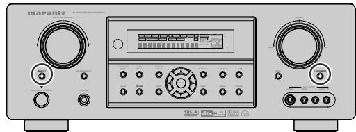
Should the operation or display seem to be abnormal, reset the unit with the following procedure.
The SR5500 is turned on, press and hold the MULTI and 7.1CH INPUT buttons simultaneously for 3 seconds or more.
Remember that the procedure will reset the settings of the function selector, Surround mode, delay time, TUNER PRESET etc., to their initial settings.
TECHNICAL SPECIFICATIONS
FM TUNER SECTION
Frequency Range. 87.5 - 108.0 MHz
Useable Sensitivity . IHF 1.8 V / 16.4 dBf
Signal to Noise Ratio............ Mono/Stereo 75/70 dB
Distortion . Mono/Stereo 0.2/0.3 %
Stereo Separation 1 kHz 45 dB
Alternate Channel Selectivity ± 300kHz 60 dB
Image Rejection 98 MHz 70 dB
Tuner Output Level 1 kHz, ±75 kHz Dev 800 mV
AM TUNER SECTION
Frequency Range. 520 - 1710 kHz
Signal to Noise Ratio 50 dB
Usable Sensitivity. Loop 400mV/m
Distortion 400Hz, 30% Mod. 0.5%
Selectivity ± 18kHz70dB
AUDIO SECTION
Power Output (20 Hz - 20 kHz/THD=0.08%)
Front L&R 8 ohms 90 W / Ch
Center 8 ohms 90 W / Ch
Surround L&R 8 ohms 90 W / Ch
Surround Back L&R 8 ohms 90 W/Ch
Front L&R 6 ohms 110 W / Ch
Center 6 ohms 110 W / Ch
Surround L&R 6 ohms 110 W / Ch
Surround Back L&R 6 ohms 110 W / Ch
Input Sensitivity/Impedance 168 mV/47 Kohms
Signal to Noise Ratio(Analog Input / Source Direct) ... 105 dB
Frequency Response
(Antalog Input / Source Direct) 8 Hz - 100 kHz (±3 dB)
(Digital Input / 96 kHz PCM) 8 Hz - 45 kHz (±3 dB)
VIDEO
Television Format NTSC
Input Level/Impedance 1 Vp-p/75 ohms
Output Level/Impedance 1 Vp-p/75 ohms
Video Frequency Response .... 5 Hz to 8 MHz (-1 dB)
Video Frequency (Component) ... 5 Hz to 80 MHz (-1 dB)
S/N 60 dB
GENERAL
Power Requirement AC 120 V 60 Hz
Power Consumption 450 W
Weight 28.7 lbs (13.0 Kg)
ACCESSIONS
Remote Control Unit RC500SR 1
AAA-size batteries 2
FM Antenna 1
AM Loop Antenna 1
Front AUX Jack Cover 1
Specifications subject to change without prior notice.
DIMENSIONS
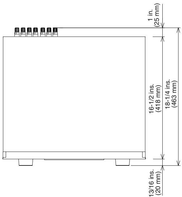
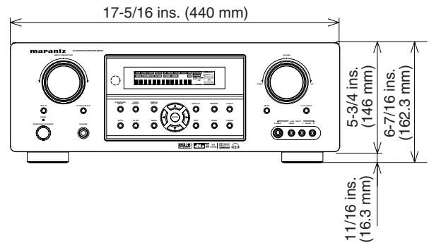
SETUP CODES
CD
Aiwa 0184
Burmester 0447
California Audio Labs 0056
Carver 0184, 0206
Classic. 0324
Denon 0030
DKK 0027
DMX Electronics 0184
Emerson 0332
Fisher 0352, 0206
Garrard 0447
Genexxa. 0059, 0332
GPX 0323
Harman/Kardon 0184, 0200, 0229
Hitachi 0059
Integra 0128
JVC 0099,0321
Kenwood 0055, 0064, 0217
KLH 0345
Koss 0344
Krell 0184
Linn 0184
Luxman 0120
LXI 0332
Magnavox. 0184, 0332
Marantz 0999,0056,0184
MCS 0056
Miro 0027
Mission 0184
MTC 0447
NSM 0184
Onkyo 0128
Optimus. 0027, 0059, 0064, 0332, 0206
0495, 0172, 0447, 0102
Panasonic 0056
Parasound 0447
Philips. 0999, 0184
Pioneer. 0059, 0332, 0495
Polk Audio 0184
Proton 0184
QED 0184
Quad 0184
Quasar 0056
RadioShack 0102
RCA. 0089, 0059, 0447, 0080,
0332, 0206, 0495
Realistic. 0447, 0206
Rotel 0184,0447
SAE 0184
Sansui 0184,0332
Sanyo 0206
Scott 0332
Sears 0332
Sharp 0064
Sonic Frontiers 0184
Sony 0027,0127,0391
Soundesign 0172
Symphonic 0332
TAG McLaren 0184
Tascam 0447
TDK 0235
Teac 0447
Technics 0056
Victor 0099
Wards 0184,0080
Yamaha 0063,0319
Zonda 0184
CDR
Classic 0324
Fisher 0352
Harman/Kardon 0229
JVC 0321
Kenwood 0999
Marantz 0999
Philips 0999
Pioneer 0089,0114
Sony 0391,0127
TDK 0235
Teac 0447
Yamaha 0319
MD PLAYERS
Denon 1900
Kenwood 1708, 1853
Marantz 1207
Onkyo 1895
Optimus 1090
Pioneer 1090
Sharp 1888
Sherwood 1094
Sony 1517
Yamaha 1915
TAPE
Aiwa 0056,0227,0224
Akai 0310
Carver 0056
Denon 0103
Fisher 0101
Garrard 0466,0335
Harman/Kardon 0209,0056
JVC 0271,0300
Kenwood 0097
Magnavox 0056
Marantz 0056,0036
Mitsubishi 0310
NAD. 0171
Onkyo 0309, 0163, 0162
Optimus. 0054, 0247, 0466, 0364
Panasonic 0256
Philips 0056
Pioneer 0054,0247,0126
Polk Audio 0056
RCA. 0054, 0247
Revox 0217
Sansui 0056,0036
Sherwood 0364
Sony 0270, 0197, 0318
Teac 0335
Technics 0256
Victor 0300
Wards 0054
Yamaha 0124,0121
SAT (DSS)
AlphaStar 0799
Chaparral 0243
Crossdigital 1136
DirecTV 0419,0593,0666,1666
1169,0274,0776,1776
0751, 0846, 1883, 1103
1136,0126,1470,1469
Dish Network System 1032, 0802, 1197
Dishpro 1032,0802
Echostar 1032,0802,1197
Expressvu 0802
GE 0593
General Instrument 0896
GOI 0802
Hitachi 0846
HTS 0802
Hughes Network Systems
1169,0776,1776,1470,1469
JVC 0802,1197
Magnavox. 0751, 0749
Memorex 0751
Mitsubishi 0776
Motorola 0896
Next Level 0896
Panasonic 0274,0728
Paysat 0751
Philips 1169,0776,1776,0751
1103, 0749, 0126, 1469
Proscan 0419, 0593
RadioShack 0896
RCA. 0419, 0593, 0882, 0170
Samsung 1303, 1136
SKY 0883
Sony 0666,1666
Star Choice 0896
Tivo 1169, 1470, 1469
Toshiba 0776,1776,0817,1312
Uniden 0751, 0749
Zenith 0883,1883
TV
Admiral 0120, 0490
Advent 0788,0869
Aiko 0119
Akai 0729,0057,0699
Albatron 0870
America Action 0207
Anam 0207
AOC 0057
Apex Digital 0775, 0792, 0906
Audiovox 0478, 0207, 0119
Bell & Howell 0181
Bradford 0207
Broksonic 0263,0490
Candle 0057
Carnivale 0057
Carver 0081
Celebrity 0027
Celera 0792
Changhong 0792
Citizen 0087,0057,0119
Clarion 0207
Contec 0207
Craig 0207
Crosley 0081
Crown 0207
Curtis Mathes 0074, 0081, 0181, 0478
0120, 0087, 0729, 0057,
0172, 0193, 1174, 1374
CXC 0207
Daewoo 0478,1688,0119,0699
Denon 0172
Dumont 0044
Durabrand 0207, 0205
Electroband 0027
Elektra 0044,1688
Emerson 0181, 0263, 0490,
0207, 0205, 0198
Envision 0057
Fisher 0181
Fujitsu. 0710, 0880, 0836
Funai 0207, 0198
Futuretech 0207
Gateway 1782, 1783
GE 0074, 0078, 0478, 0205
1474, 1374, 1174
Gibraltar 0044, 0057
GoldStar 0057, 0205
Grunpy 0207
Hallmark 0205
Harman/Kardon 0081
Harvard 0207
Havermy 0120
Hello Kitty 0478
Himitsu 0207
Hisense 0775
Hitachi 1172,0172
Infinity 0081
Inteq 0044
JBL 0081
JCB 0027
Jensen 0788
JVC 0080
KEC 0207
Kenwood 0057
KLH 0792
KTV 0207,0057
LG 1205,0883,0469
LXI. 0074, 0081, 0181, 0183, 0205
Magnavox.....0081,0057,1481,0733,1281
Marantz 0081,0057,1581,0731
Matsushita 0277, 0677
Megatron 0205, 0172
Memorex 0181, 0490, 0177, 0205
MGA 0177,0057,0205
Midland. 0074, 0044, 0078
Mitsubishi.....0120,0177,1277,0205,0863
Monivision 0870
Motorola 0120
MTC 0087,0057
Multitech 0207
NAD. 0183, 0205
NEC. 0057, 1731
Nikko 0057,0205,0119
Norcent. 0775, 0851
NTC 0119
Onwa 0207
Optimus 0181, 0277, 0193, 0677
Optonica 0120
Orion 0263, 0490
Panasonic 0277,0078,0677
Penney 0074,0183,0078,0087
0057, 0205, 1374
Philco 0081,0057
Philips. 0081, 1481, 0717
Pilot 0057
Pioneer 0193,0706
Portland 0119
Prima 0788
Prism 0078
Proscan 0074,1474,1374
Proton 0205
Pulsar 0044
Quasar 0277,0078,0677
RadioShack... 0074, 0181, 0207, 0057, 0205
RCA. 0074, 1474, 1274, 1574,
0117, 1174, 1074, 1374, 0706
Realistic. 0181, 0207, 0057, 0205
Runco 0044,0057
Sampo 0057,1782
Samsung 0087, 0729, 0057, 0205
Sansui 0490
Sanyo 0181
Scotch 0205
Scott 0263, 0207, 0205
Sears...0074,0081,0181,0183,0205,0198
Sharp 0120
Sheng Chia 0120
Sony 0027
Soundesign 0207, 0205
Squareview 0198
SSS 0207
Starlite 0207
Studio Experience 0870
Supreme 0027
SVA 0775,0892
Sylvania. 0081, 0057, 0198
Symphonic 0207, 0198
Tandy 0120
Tatung 1783
Technics 0277,0078
Techwood 0078
Teknika. 0081, 0207, 0177, 0087, 0119
Telefunken 0729
TMK 0205
TNCi 0044
Toshiba 0181,0183,0087,1283
1383, 1183, 1731, 0677
TVS 0490
Vector Research 0057
Victor 0080
Vidikron 0081
Vidtech 0205
Viewsonic 1782
Wards. 0081, 0057, 0205, 1183
Waycon 0183
White Westinghouse 0490
Yamaha 0057
Zenith 0044, 0490, 0205, 0119
Fisher 0074, 0131
Fuji 0062, 0060
Funai 0027
Garrard 0027
GE ....0087, 0062, 0267, 1087, 1062, 0834
GoldStar 0064,1264
Gradiente 0027
Harley Davidson 0027
Harman/Kardon 0108
HI-Q. 0074
Hitachi 0027, 0069
Hughes Network Systems 0069
JVC 0094
KEC 0064
Kenwood 0094
Kodak 0062,0064
Lloyd's 0027
LXI 0064
Magnasonic 1305
Magnavox.....0062,0066,0108,0027,1808
Magnin 0267
Marantz 0062,0108,1408
Marta 0064
Matsushita 0062, 0189
MEI 0062
Memorex.....0062,0189,0064,0075,0066
0074, 0267, 0027, 0131, 0236, 1264
MGA 0267,0070
MGN Technology 0267
Minolta 0069
Mitsubishi 0094,0070,0834
Motorola 0062, 0075
MTC 0267,0027
Multitech 0027
NAD 0085
NEC. 0131, 0094
Nikko 0064
Noblex 0267
Olympus 0062
Optimus 1089, 0189, 0064,
0075, 0131, 0085
Orion 0211, 0236, 1506
Panasonic 1089, 0062, 0189
0252,1062,0643
Penney 0062, 0064, 0267
0069, 1264, 1062
Pentax 0069
Philco 0062
Philips 0062, 0108, 0645
Pilot 0064
Pioneer 0094,0085
Polk Audio 0108
Profitronic 0267
Proscan 0087,1087
Pulsar 0066
Quasar 0062, 0189, 1062
RadioShack 0027
Radix 0064
Randex 0064
RCA. 0087, 0267, 0069, 1062
0907, 0085, 0834, 1087
Realistic. 0062, 0064, 0075,
0074, 0027, 0131
ReplayTV 0643
Runco 0066
Samsung 0267,0072,1041
Sanky 0075, 0066
Sansui 0027,0094,0236,1506
Sanyo 0074,0267,0131
Scott 0211, 0072, 0148, 0070
Sears 0062, 0064, 0074, 0027
0069, 0131, 1264
Sharp 0075, 0834
Shogun 0267
Sonic Blue 0643
Sony....0062,0059,0060,0027,1259,0663
STS 0069
Sylvania. 0062, 0108, 0027, 0070, 1808
Symphonic 0027
Teac 0027
Technics 0062, 0189
Teknika 0062,0064,0027
Thomas 0027
Tivo 1530,0663,0645
TMK 0267
Toshiba 0072, 0070, 1530, 1172, 0872
Totevision 0064, 0267
Unitech 0267
Vector 0072
Video Concepts 0072
Videomagic 0064
Videosonic 0267
Villain 0027
Wards 0087, 0062, 0075, 0074
0108, 0267, 0027, 0069
White Westinghouse 0236
XR-1000 0062,0027
Zenith 0066, 0060, 0027, 0236, 1506
DVD
Aiwa 0668
Allegro 0896
Apex Digital 0699, 0823, 1031, 1127,
0821, 0857, 1088, 0824, 1047
Blue Parade 0598
Broksonic 0722
CineVision 0903,0896
Curtis Mathes 1114
CyberHome 1050,0843,1051
Daewoo 0896,0860
Denon 0517
DVD2000 0548
Emerson. 0618, 0848
Enterprise 0618
GE 0549,0842
Go Video 0860, 0742, 0896
Harman/Kardon 0729,0609
Hitachi 0600
Hiteker 0699
JBL 0729
JVC 0585,0650,0894
Kenwood 0517,0561
KLH 1047
Koss 0678
Magnavox. 0530, 0848
Marantz 0566
Memorex 0722
Microsoft 0549
Mintek. 0866
Mitsubishi 1548,0548
Onkyo 0530
Oritron 0678
Panasonic 0517, 1789, 1389
Philips. 0530, 0566, 0673, 0881
Pioneer 0552,0598
Polaroid 1088
Polk Audio 0566
Proscan 0549
Qwestar 0678
RCA. 0549, 0598, 0849, 1049
Rio 0896
Rotel 0650
Sampo 0779
Samsung 0517,0600,0847
Sansui 0722
Sanyo 0722
Sharp. 0657, 0779
Shinsonic. 0560, 0866
Sonic Blue 0896
Sony 0560,0891,1060
Superscan 0848
Sylvania. 0848
Technics 0517
Theta Digital 0598
Toshiba 0530,1072,0722
Tregex 0826
Urban Concepts 0530
US Logic 0866
Xbox 0549
Yamaha 0517,0566,0572
Zenith 0530, 0618, 0896
www.marantz.com
You can find your nearest authorized distributor or dealer on our website.
| JAPAN | Marantz Japan, Inc. | 35-1 Sagami Ohno 7-Chome, Sagamihara-shi, Kanagawa 228-8505, Japan |
| U.S.A. | Marantz America, Inc. | 1100 Maplewood Drive, Itasca, IL 60143, U.S.A. |
| EUROPE | Marantz Europe B.V. | P.O. Box 8744, 5605 LS Eindhoven, The Netherlands |
Manufactured under license from Dolby Laboratories. "Dolby", "Pro Logic" and the double-D symbol are trademarks of Dolby Laboratories.
Confidential Unpublished Works. © 1992-1997 Dolby Laboratories, Inc. All rights reserved.
marantz® is a registered trademark.
Printed in China

08/2004 00M08BW851250 ecmf-e
- CAUTION
- WARNING
- NOTE TO CATV SYSTEM INSTALLER:
- NOTE:
- IMPORTANT SAFETY INSTRUCTIONS
- READ BEFORE OPERATING EQUIPMENT
- PRECAUTIONS
- CAUTIONS ON INSTALLATION
- HSITONE
- DESCRIPTION
- DIGITAL
- EXTENDED
- About Dolby Pro Logic IIx
- FEATURES
- ACCESSORIES
- FRONT PANEL
- ① POWER switch and STANDBY indicator
- ② MULTI (Multi Room) button
- ③ INPUT SELECTOR knob (AUDIO/VIDEO)
- M.(Multi Room) SPEAKER B button
- ⑤ INFRARED receiving sensor window
- ⑥ SURROUND MODE button
- ⑦ PURE DIRECT button
- Notes:
- SIMPLE SETUP button
- ⑨ DISPLAY button
- MEMORY button
- CLEAR button
- VOLUME control knob
- 7.1CH INPUT button
- MUTE button
- T-MODE button
- BAND button
- EXIT button
- Cursor ( , , ,) /ENTER button
- MENU button
- HT-EQ button
- AUTO (Auto surround) button
- HEADPHONE jack for stereo headphones
- AUX1 INPUT jacks
- FL DISPLAY
- DISP(Display Off) indicator
- SLEEP timer indicator
- Multi-room system indicator
- AUTO SURR (Auto Surround mode) indicator
- TUNER's indicators
- DTS-ES mode indicators (DISC6.1, MTX6.1)
- V(video)-OFF mode indicator
- NIGHT mode indicator
- SPKR (speaker) B indicator
- PEAK indicator
- EQ mode indicator
- ATT (Attenuation) indicator
- DIGITAL Input Indicator
- ANALOG input indicator
- SIGNAL FORMAT indicators
- ENCODED CHANNEL STATUS indicators
- Main Information Display
- DIRECT (Puredirect) indicator
- HOW TO ATTACH THE FRONT AUX JACK COVER
- REAR PANEL
- VIDEO IN/OUT (TV, DVD, VCR1, DSS/VCR2)
- FM antenna terminal (75 ohms)
- AM antenna and ground terminals
- RS-232C
- COMPONENTVIDEOINPUT/OUTPUT
- MONITOR OUT
- Preamp Outputs
- (L, R, SL, SR, SBL, SBR, C)
- Power cable
- AC OUTLETS
- Caution:
- Speaker outputs terminals
- Subwoofer Output
- CHANNEL or AUX2 INPUT
- Multiroom Outputs (Audio L&R)
- MULTI ROOM REMOTE IN/OUT terminals
- REMOTE CONT. IN/OUT terminals
- AUDIO IN/OUT (CD, TAPE, CD-R, TV, DVD, VCR1, DSS/VR2)
- DIGITAL INPUT (Dig.1 - 4) / OUTPUT (coaxial, optical)
- PURE DIRECT button
- SETUP/T.TONE button
- OSD button
- SLEEP (sleep timer) button
- TV VOLUME UP () /DOWN () buttons
- PROGRAMMING THE REMOTE CONTROLLER
- Important:
- PROGRAMMING WITH THE 4-DIGIT CODE
- SCANNING THE CODE TABLE
- CHECKING THE CODE
- RESETTING THE ALL CODE
- Remote-controllable range
- LOADING BATTERIES
- Remove the back cover.
- Insert the new batteries (AAA type) with correct and polarity.
- Close the cover until it clicks.
- CAUTIONS ON BATTERIES
- GENERAL INFORMATION OF RC5500SR TO SR5500
- AMP MODE
- TUNER MODE
- CONNECTIONS
- SPEAKER PLACEMENT
- Front left and right speakers
- Center speaker
- Surround left and right speakers
- Surround back left and right speakers
- Subwoofer
- HEIGHT OF THE SPEAKER UNITS
- CONNECTING SPEAKERS
- CONNECTING SPEAKER WIRE
- CONNECTING A SUBWOOFER
- CONNECTING AUDIO COMPONENTS
- CONNECTING DIGITAL AUDIO COMPONENTS
- CONNECTINGVIDEOCOMPONENTS
- VIDEO.S-VIDEO,.COMPONENTJACKS
- VIDEO jack
- S-VIDEO jack
- Component jack
- ADVANCED CONNECTING
- CONNECTING MULTI CHANNEL AUDIO SOURCE
- CONNECTING AN EXTERNAL POWER AMPLIFIER
- CONNECTING THE REMOTE CONTROL JACKS
- CONNECTING THE ANTENNA TERMINALS
- ASSEMBLING THE AM LOOP ANTENNA
- CONNECTING THE SUPPLIED ANTENNAS
- Connecting the supplied FM antenna
- Connecting the supplied AM loop antenna
- CONNECTING AN FM OUTDOOR ANTENNA
- CONNECTING AN AM OUTDOOR ANTENNA
- SETUP
- INPUT SETUP (ASSIGNABLE DIGITAL INPUT AND COMPONENT VIDEO INPUT)
- SPEAKER SETUP
- 2-1 SPEAKERS SIZE
- LARGE:
- SMALL:
- SUBWOOFER:
- YES:
- NONE:
- FRONT L/R
- CENTER
- SURROUND L/R
- SURR. BACK
- 2CH:
- 1CH:
- SURR. BACK SIZE
- LPF/HPF
- 80Hz:
- 100Hz:
- 120Hz
- BASS MIX
- 2-2 SPEAKERS DISTANCE
- FRONT L:
- FRONT R:
- CENTER:
- SUBR.L:
- SURR. R:
- SUB W:
- SURR.BL:
- SURR.BR:
- 2-3 SPEAKERS LEVEL
- TEST MODE :
- PREFERENCE
- STANDBY MODE:
- TV AUTO:
- OSD Info:
- VIDEO CONVERT:
- SURROUND
- SURR Modes:
- HT-EQ:
- LFE LEVEL:
- PL II (PRO LOGIC II) MUSIC PARAMETER
- PARAMETER:
- PANorama:
- DIMENSION:
- CENTERWIDTH:
- CS II (CIRCLE SURROUND II) PARAMETER
- TRUBASS:
- SRS DIALOG:
- MULTI ROOM
- SLEEP TIMER:
- MULTI (MULTI ROOM):
- VOL (VOLUME SETUP):
- LEVEL (VOLUME LEVEL):
- MSPK B (MULTI SPEAKER B):
- MAIN ROOM STATUS:
- 7.1 CH INPUT LEVEL
- SIMPLE SETUP
- BASIC OPERATION
- (PLAY BACK)
- SELECTING AN INPUT SOURCE
- VIDEO CONVERT
- Example:
- Notes of OSD menu:
- ADJUSTING THE MAIN VOLUME
- ADJUSTING THE TONE (BASS & TREBLE) CONTROL
- (Using the remote control unit)
- TEMPORARILY TURNING OFF THE SOUND
- USING THE SLEEP TIMER
- NIGHT MODE
- SURROUND MODE
- AUTO
- MODE
- (Dolby Digital, Pro Logic IIx MOVIE, Pro Logic IIx MUSIC, Pro Logic IIx GAME, Pro Logic)
- DOLBY DIGITAL
- Pro Logic IIx MOVIE
- Pro Logic IIx MUSIC
- Pro Logic IIx GAME
- Pro Logic
- EX/ES
- Dolby Digital EX
- DTS-ES (Discrete 6.1, Matrix 6.1)
- dtsmODE
- (dts, Neo:6 Cinema, Neo:6 Music)
- MULTICH.ST
- CIRCLE SURROUND II
- (CSII-CINEMA, CSII-MUSIC, CSII-MONO)
- VIRTUAL
- STEREO
- PURE-DIRECT
- NOTE for DTS signal
- NOTE for Dolby Digital Surround EX signal
- NOTE for 96kHz PCM audio
- The relation between the selected surround mode and the input signal
- Abbreviations
- OTHER FUNCTION
- TV AUTO ON/OFF FUNCTION
- AUTO POWER ON
- AUTO POWER OFF
- ATTENUATION TO ANALOG INPUT SIGNAL
- LISTENING THROUGH HEADPHONES
- DOLBY HEADPHONE MODE
- VIDEO ON/OFF
- DISPLAY MODE
- SELECTING ANALOG AUDIO INPUT OR DIGITAL AUDIO INPUT
- RECORDING AN ANALOG SOURCE
- To record the input source signal you are currently watching or listening to
- Recording the video from one source and the audio from another
- HT-EQ
- CH INPUT
- AUX2 INPUT
- LIP.SYNC
- (Using the SR5500)
- HSITON
- (FM) TUNING MODE (AUTO STEREO OR MONO)
- PRESET MEMORY
- AUTO PRESET MEMORY
- MANUAL PRESET MEMORY
- RECALLING A PRESET STATION
- PRESET SCAN
- CLEARING STORED PRESET STATIONS
- SORTING PRESET STATIONS
- NAME INPUT OF THE PRESET STATION.
- MULTI ROOM SYSTEM
- MULTI ROOM PLAYBACK USING THE MULTI ROOM OUT TERMINALS
- MULTI ROOM PLAYBACK USING THE MULTI SPEAKER TERMINALS
- Notes for MULTI ROOM SPEAKER
- TROUBLESHOOTING
- In case of trouble, check the following before calling for service:
- GENERAL MALFUNCTION
- Memory backup
- HOW TO RESET THE UNIT
- TECHNICAL SPECIFICATIONS
- FM TUNER SECTION
- AM TUNER SECTION
- AUDIO SECTION
- VIDEO
- GENERAL
- ACCESSIONS
- DIMENSIONS
- SETUP CODES
- CD
- CDR
- MD PLAYERS
- TAPE
- SAT (DSS)
- TV
- DVD
- www.marantz.com
Brand : MARANTZ
Model : RC 5500SR
Category : Universal remote