
Multishape 2000 Liberty - Washing machine CECOTEC - Free user manual and instructions
Find the device manual for free Multishape 2000 Liberty CECOTEC in PDF.


User questions about Multishape 2000 Liberty CECOTEC
0 question about this device. Answer the ones you know or ask your own.
Ask a new question about this device
Download the instructions for your Washing machine in PDF format for free! Find your manual Multishape 2000 Liberty - CECOTEC and take your electronic device back in hand. On this page are published all the documents necessary for the use of your device. Multishape 2000 Liberty by CECOTEC.
USER MANUAL Multishape 2000 Liberty CECOTEC
EN • The coding in this manual is generic and applies to all code variants of the appliance.
⚠ WARNING: Read all hazard warnings, instructions, figures and technical specifications supplied with the power tool. Failure to follow all instructions listed below may result in electric shock, fire and/or serious injury.
Keep all safety warnings and instructions for future reference. The term “power tool” in the warnings refers to your mains-operated (corded) power tool or battery-operated (cordless) power tool.
Work area safety
a. Keep the work area clean and well lit. Cluttered or dark areas may cause accidents.
b. Do not operate power tools in explosive atmospheres, such as in the presence of flammable liquids, gases or dust. Power tools can produce sparks that ignite dust or fumes.
c. Keep children and bystanders away while operating a power tool. Distractions can cause you to lose control.
Electrical safety
a. Power tool plugs must match the outlet. Never modify the plug in any way. Do not use adapters on grounded power tools. Unmodified plugs and matching sockets will reduce the risk of electric shock.
b. Avoid body contact with grounded surfaces, like pipes, radiators, stoves and refrigerators. There is an increased risk of electric shock if your body is earthed or grounded.
c. Do not expose power tools to rain or wet conditions. Water entering a power tool will increase the risk of electric shock.
d. Do not misuse the cord. Never use the cord for carrying, pulling or unplugging the power tool. Keep cord away from heat, oil, sharp edges or moving parts. Damaged or entangled
cords increase the risk of electric shock.
e. When operating a power tool outdoors, use an extension cord suitable for outdoor use. Use of a cord suitable for outdoor use reduces the risk of electric shock.
f. If operating a power tool in a damp location is unavoidable, use a residual current device (RCD) protected supply. The use of a differential fuse reduces the risk of exposure to electric shock.
Personal safety
a. Stay alert, watch what you are doing and use commonsense when operating a power tool. Do not use a power tool while you are tired or under the influence of drugs, alcohol or medication. Failure to exercise caution when operating the power tool may result in serious injury.
b. Use personal protective equipment. Always wear eye protection. Protective equipment such as dust mask, non-skid safety footwear, helmet or hearing protection, used under appropriate conditions, will reduce personal injuries.
c. Avoid unintentional start-up. Ensure the power tool is switched off before connecting to the power supply and/or battery pack, picking up or carrying the tool. If you carry the power tool by holding it by the on/off switch, or if you power the power tool while it is switched on, this may result in an accident. Remove adjustment tools or spanners before connecting the power tool. An adjustment tool or spanner left on a rotating part may cause injury when the power tool is started.
d. Avoid awkward postures. Keep proper footing and balance at all times. This will enable you to control the power tool better should an unexpected situation arise.
e. Wear appropriate work clothing. Do not wear loose clothing or jewellery. Keep your hair and clothing away from moving parts. Loose clothing, long hair and jewellery can become caught in moving parts.
f. If devices are provided for the connection of dust extraction and collection facilities, ensure these are connected and properly used. The use of this equipment reduces dust-related risks.
g. Do not let familiarity gained from frequent use of tools allow you to become complacent and ignore tool safety principles. A careless action can cause serious injury within a fraction of a second.
Power tool use and maintenance
a. Do not overload the power tool. Use the correct power tool for your application. With the appropriate power tool you will work better and more safely within the specified power range.
b. Do not use the power tool if the switch is faulty. Power tools that cannot be switched on or off are dangerous and must be repaired.
c. Remove the plug from the mains and/or remove the detachable battery from the power tool before making any adjustment, changing accessories or storing the power tool. Such preventive safety measures reduce the risk of the power tool starting up accidentally.
d. Store power tools out of the reach of children. Do not allow persons unfamiliar with the power tool or who have not read these instructions to operate the power tool. Power tools used by inexperienced persons are dangerous.
e. Check the power tool and its accessories. Check if the moving parts are misaligned or stuck, if there are broken pieces or any
other condition that may affect the power tool's operation. In case of damage, the power tool must be repaired before use. Many accidents are due to poorly maintained power tools.
f. Keep tools clean and sharp. Properly maintained tools are better guided and controlled.
g. Use the power tool, accessories, etc. according to these instructions, taking into account the working conditions and the work to be carried out. The use of power tools for work other than that for which they are intended can be dangerous.
h. Keep handles and gripping surfaces dry, clean and free of oil and grease. Slippery handles and grasping surfaces do not allow safe handling and control of the tool in unexpected situations.
Service
a. Only have your power tool repaired by a qualified expert, using only original spare parts. This is the only way to maintain the safety of the power tool.
b. Do not perform any maintenance on defective batteries. Only the manufacturer or the authorized technical assistance service can perform maintenance on the batteries.
Cordless tool use and handling
a. Only charge the battery with the recommended chargers. The use of a charger with a battery that does not correspond to it entails danger of fire.
b. Use only the batteries indicated for the power tools. Use of other batteries may cause injury and fire hazard.
c. Keep unused batteries away from staples, coins, keys, nails, screws or other small metal objects that can cause bridging of the contacts. A short circuit between the battery terminals
can cause burns or fire.
d. Incorrect use may result in leakage of battery fluids. Avoid contact with such liquids. In case of accidental contact, rinse the affected part with water. If the liquid comes into contact with eyes, seek medical assistance immediately. Liquid leaking from the battery may cause skin irritation or burns.
e. Do not use a damaged or modified battery. Damaged or modified batteries may operate unexpectedly and cause fire, explosion or danger of injury.
f. Do not expose the battery to fire or high temperatures. Fire or temperatures above 130\ °C ( 265\ °F ) can cause explosions.
g. Follow all charging instructions and do not charge the battery or the tool outside the temperature range specified in the instructions. Improper charging or charging at temperatures outside the specified range may damage the battery and increase the risk of fire.
⚠️ BEWARE! RISK OF EXPLOSION! Never recharge non-rechargeable batteries.
Protect the battery against heat, e.g. also against strong sunlight, fire, water and moisture. Danger of explosion.
SAFETY WARNINGS FOR ROUTERS
a. Hold the power tool by insulated gripping surfaces only, as the cutting tool may contact its own cord. When cutting a “live” wire, exposed metal parts of the power tool may become “live” and could give the operator an electric shock.
b. Use clamps or other practical method to secure and fasten the workpiece to a stable platform. Holding the workpiece by hand or against your body leaves it unstable and may lead to loss of control.
c. The allowed speed of the router must be at least as high as the maximum speed indicated on the power tool. Router bits rotating faster than the allowed speed may break and fly away.
d. The router or other accessories must fit exactly into the tool holder (collets) of your power tool. Tools that do not fit properly in the power tool holder, when rotated off-center, generate excessive vibrations and can cause you to lose control of the tool.
e. Only bring the power tool in operation close to the workpiece. Otherwise, the tool may suddenly move backwards when the tool gets caught in the workpiece.
f. Do not insert your hands into the milling area and router bit. Hold the additional handle with your second hand. If the router is held with both hands, they cannot be injured by the router bit.
g. Never mill over metal objects, nails or screws. This could damage the router bit and cause excessive vibrations.
h. Use suitable scanning devices to detect hidden conductors or pipes, or consult your utility companies. Contact with electrical conductors can cause fire or electrocution. Damaging a gas pipe can cause an explosion. Drilling into a water pipe may result in property damage or electric shock hazard.
i. Do not use nicked or damaged router bits. Dented or damaged router bits increase friction, can snag, and cause imbalance.
j. Wait until the power tool has stopped before putting it down. The tool may snag and cause you to lose control of the power tool.
k. While working, hold the power tool firmly with both hands and take care of a safe position. By using both hands the power tool is guided more safely.
CONSIGNES GÉNÉRALES DE SÉCURITÉ POUR LES OUTILS ÉLECTRIQUES
- Start/Stop button
- Lock/unlock button
- Lock lever
- Depth scale
- Adjustment screw
- Base plate
- Battery
- Speed setting dial
- Handle
- Base plate protector
Note:
The graphics in this manual are schematic representations and may not exactly match the product.
2. BEFORE USE
- This appliance comes in a packaging designed to protect it during transport. Remove the appliance from its box. You can keep the original box and other packaging materials in a safe place to prevent damage to the appliance if you need to transport it in the future. If you wish to dispose of the original packaging, make sure all items are recycled properly.
- Check that all parts and components are included and in good condition. If any of them are missing or damaged, please contact Cecotec's Official Technical Support Service immediately.
Box content:
- Cordless router
- Battery
- Charger
- Router bits x5
- Parallel guide with support
- Curved edge guide
- Template guide
- Vacuum cleaner adapter
- Key x2
- Clamping chuck x2 plus 1 installed
-
Wing nut and bolt
-
Carbon brushes x2
- Do not remove the product's serial number in order to keep proper traceability if technical assistance is required.
3. INSTALLATION
ATTENTION!
Before installing or removing accessories, make sure the tool is turned off and remove the battery to avoid accidental activation.
Instructions for charging the battery
The charger of this tool has a plug-in type design, where the charging plug is inserted into the battery charging port.
The charger has two indicators: red and green. The red indicator shows that charging is in progress, while the green indicator shows that charging is complete.
- Plug the charger into a power socket.
- Insert the Type-C charging cable into the battery charging port.
- Check the state of charge. The red indicator will light up, indicating that the battery is charging.
- When the battery is fully charged, the green indicator light will light up.
- When charging is complete, unplug the battery charger and disconnect it from the power socket.
- Check the battery charge level (Optional).
Battery installation
Align the battery pack with the slot in the tool and then slide it into place until it locks and clicks.
Removing the battery
To remove the battery, press the button on the front of the battery pack and simultaneously remove the battery pack from the tool.
Installing or removing the router bit
IMPORTANT: Do not tighten the collet nut without inserting the bur. The clamp cone may break.
- Insert the router bit fully into the collet chuck.
-
Tighten the clamp nut firmly with the two wrenches.
-
To remove the router bit, follow the installation procedure in reverse.
Figures 2 and 3
- Tighten
- Loosen
- Hold
- Shaft lock
Using the router
CAUTION: Always hold the tool firmly with one hand on the housing. Do not touch the metal part.
- Place the tool base on the workpiece to be cut without the router bit coming into contact with it.
- Switch on the tool and wait until the bit reaches full speed.
- Move the tool over the workpiece surface, keeping the tool base and router base plate flush with the sides of the workpiece, and advance smoothly until cutting is complete.
- When performing edge cuts, the workpiece surface must be on the left-hand side of the router bit in the feed direction.
Fig. 4
- Workpiece
- Drill bit direction of rotation
- View from tool top
- Direction of travel
Notes:
- Moving the tool forward too quickly may cause poor cutting quality or damage to the bit or motor.
- Moving the tool forward too slowly may burn and mar the cut. The proper feed rate will depend on the bit size, workpiece type and depth of cut.
- Before beginning the cut on the actual workpiece, it is advisable to make a sample cut on a piece of scrap wood. This will show exactly how the cut will look and allow you to verify dimensions.
Template guide
The template guide provides a hole through which the bit passes, allowing the use of the router with template patterns. Fig. 5
- Loosen the screws and remove the base protector.
- Place the template guide on the base and replace the base protector.
Fig. 6
- Base protector
-
Screws
-
Place the template guide on the tool base. There are four convex bulges on the guide. Secure two of the four convex parts using the two screws. Install the tool base.
- Secure the template to the workpiece. Place the tool on the template and move the tool with the template guide sliding along the template side.
NOTE:
The workpiece will be cut slightly differently from the template size. Allow for the distance (X) between the router bit and the outside of the template guide. The distance (X) can be calculated using the following equation:
Distance (X) = (outer diameter of template guide - router bit diameter) / 2
Straight guide
The straight guide is effectively used for straight cuts when chamfering. Fig. 7
- To ensure cutting accuracy, secure the guide plate to the straight guide using the bolt and wing nut.
Fig. 8
- Straight guide
- Bolt
- Guide plate
-
Wing nut
-
Loosen the wing bolts, hold the base horizontally, then mount the straight guide with the clamping screw.
Fig. 9
- Straight guide
- Base
- Wing nut
-
Locking screw
-
Ensure the guide is firmly secured to prevent movement during operation.
- Loosen the wing nut on the straight guide and adjust the distance between the router bit and the straight guide. At the desired distance, tighten the wing nut firmly.
- When cutting, move the tool with the straight guide flush against the side of the workpiece.
Straight guide for circular works
Figure 10
- Straight guide
- Bolt
- Guide plate
- Wing nut
- Centre hole
NOTE:
Circles with a radius between 172 mm and 186 mm cannot be cut with this guide.
NOTE:
You can use both holes to achieve different radii.
- Align the centre hole of the straight guide with the centre of the circle to be cut.
- Drive a nail less than 6 mm in diameter into the centre hole to secure the straight guide.
- Rotate the tool clockwise around the nail.
Figure 11
- Straight guide
- Centre hole
Trimming guide
Milling edges and making curved cuts in veneers for furniture and similar tasks can be done easily with the trimming guide. The guide roller rides the curve and ensures a fine cut. Fig. 12
- Loosen the wing bolts and hold the base horizontally.
- Install the trimming guide and guide holder to the base with the clamping screw (A).
- Loosen clamping screw (B) and adjust the distance between the router bit and trimming guide by turning the adjusting screw (1 mm per turn). At the desired distance, tighten clamping screw (B) to secure the trimming guide in place.
Fig. 13
- Fastening screw (A)
- Adjustment screw
- Fastening screw (B)
-
Trimming guide
-
When cutting, move the tool with the guide roller riding against the side of the workpiece.
VACUUM CLEANER ADAPTER
- Place the suction adapter in the side hole as shown in figure 14.
Fig. 14
- Vacuum cleaner adapter
- Screw
Replacing the drill chuck on your router
Follow these steps to replace the drill chuck on your router. This process is applicable to change between the two drill chucks included: 6 mm or 8 mm.
- Make sure the router is switched off and disconnected from any power source before starting.
- Unscrew and remove the nut from the chuck that holds it in place.
- Carefully remove the old drill chuck from the shaft. You may need to move it slightly to loosen its grip.
- Insert the new chuck that matches the size of the drill bit you plan to use (either 6 mm or 8 mm). Make sure it is tight and correctly positioned inside the shaft.
- Replace the chuck nut and tighten it to secure the new chuck firmly in place. Make sure the nut is tight enough to prevent the chuck from slipping during operation.
- After replacing the drill chuck, run the router with no load to make sure everything is secure and running smoothly without excessive vibrations or noise.
These steps will help you change the drill chuck safely and effectively on your router, ensuring proper and safe operation of the equipment.
4. OPERATION
Switch Operation
The tool has 2 buttons to control it: lock/unlock button and start/stop button.
On/Off
- Press the lock/unlock button. The tool will enter standby mode
- To start the tool, press the start/stop button when the tool is in standby mode.
- To stop the tool, press the start/stop button again. The tool will return to standby mode.
- To turn the tool completely off, press the lock/unlock button in standby mode.
- If the tool is left for 10 seconds without any operation in standby mode, it will automatically switch off.
Milling address
When using a router, it is important to move the tool in the correct direction relative to the router bit rotation.
- Clockwise router bit rotation (Standard): The router bit rotates clockwise (viewed from above). In this case, the tool should move counterclockwise along the edge of the workpiece if you are working on the outer edge. This is known as conventional routing and provides safer, more controlled operation as the router bit cuts into the material rather than pulling away from it.
- For internal cuts (e.g. milling of an internal contour): The tool must move clockwise to ensure conventional milling inside the workpiece.
- When using an inclined base or template: Always move the tool in the opposite direction to the router bit rotation to maintain stable control and precise operation.
Note: Moving the router in the wrong direction can cause uncontrolled tool movement, reduce work quality and increase the risk of injury.

⚠️ Important: Conventional milling (moving the tool in the opposite direction of cutter rotation) is always preferable for most operations.
Speed dial
The tool speed dial allows the motor speed to be adjusted in six different steps, ranging from 16,000 to 35,000 revolutions per minute (RPM). This stepwise adjustment provides precise control over speed, making it easy to adapt the router's performance to different materials and cutting tasks.
- To adjust the speed, turn the dial to the desired setting. Low settings, between 1 and 3, are ideal for harder materials or when more control is needed during coarser operations. The higher settings, 4 to 6, are suitable for detailed work and cutting softer materials.

⚠️ Important! Do not attempt to adjust the speed beyond the marked range of 1 to 6. Attempting to force the dial beyond these settings may result in tool malfunction, motor overheating and potentially cause damage to the router. Always keep the dial within the specified settings for safe and efficient use.
Cutting depth
Trimming base
The cutting depth can be adjusted as required.
- Open the locking lever: Start by releasing the locking lever.
- Adjusting the cutting depth: Move the tool base up or down by turning the adjustment screw located under the lever until the desired depth is reached.
- Secure the locking lever: Once the depth is set, firmly close the locking lever. If additional adjustment is required, tighten the hex nut on the lever. Turn the nut clockwise to increase the tension or counterclockwise to loosen it.

⚠️ Important: Avoid over-tightening, as this may damage the tool. However, make sure that the lever is tightened securely to avoid loosening, which could result in loss of control during operation.
5. CLEANING AND MAINTENANCE

Always make sure that the tool is switched off and the battery has been removed before carrying out preventive maintenance work.
- After each use, wipe the tool with a clean, dry cloth to remove dust, debris and debris. Pay special attention to the ventilation slots to avoid blockages that may cause overheating.
- Routinely check for any signs of wear or damage, especially to moving parts such as the clamp, base plates and power cord. Replace any worn or damaged parts immediately to maintain safe and efficient operation.
- Ensure the collet and router bit are clean and properly tightened before each use. A loose router bit can cause vibrations and potentially damage the tool or workpiece.
- When not in use, store the tool in a dry, dust-free environment. Use the bag provided or a dedicated storage space to protect it from physical damage.
- For safe and reliable operation of the tool, please note that repair, maintenance and adjustment of the tool must be carried out at service centres using only original spare parts and consumables.
6. RECYCLING OF ELECTRICAL AND ELECTRONIC EQUIPMENT
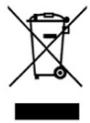
This symbol indicates that, according to the applicable regulations, the product and/or battery must be disposed of separately from household waste. When this product reaches the end of its shelf life, you should dispose of the batteries/accumulators and take them to a collection point designated by the local authorities.

For detailed information on how to properly dispose of electrical and electronic equipment and/or the corresponding batteries, consumers should contact their local authorities.
Compliance with the above guidelines will help protecting the environment.
Information regarding national packaging recycling systems and their marking can be found on our website.
7. COPYRIGHT
The intellectual property rights over the texts in this manual belong to CECOTEC INNOVACIONES, S.L. All rights reserved. The content of this publication may not, either in part or in its entirety, be reproduced, stored in a retrieval system, transmitted or distributed by any means (electronic, mechanical, photocopying, recording or similar) without prior authorisation from CECOTEC INNOVACIONES, S.L.
8. DECLARATION OF CONFORMITY
MANUFACTURER: CECOTEC INNOVACIONES S.L
ADDRESS: Av. Reyes Católicos, 60, 46910, Alfafar, Valencia (Spain)
DESCRIPTION: Router
PRODUCT IDENTIFICATION: MultiShape 2000 Liberty Router
FUNCTION: Cutting
MODEL: A01_EU01_111981
It certifies that the product described has been designed, manufactured and tested and complies with all applicable requirements.
EU DIRECTIVES IMPLEMENTED:
- Directive 2014/35/EU on the harmonisation of the laws of the Member States relating to the making available on the market of electrical equipment designed for use within certain voltage limits.
- Directive 2014/30/EU on the harmonisation of the laws of the Member States relating to electromagnetic compatibility.
- Directive 2011/65/EU and delegated directive (EU) 2015/863 on the restriction of the use of certain hazardous substances in electrical and electronic equipment.
APPLICABLE HARMONISED NORMS:
- EN 62841-1:2015+A11
-
EN 62841-2-17:2017
-
EN IEC 55014-1:2021
- EN IEC 55014-2:2021
- EN IEC 61000-3-2:2019+A1+A2
- EN 61000-3-3:201+A2
- IEC 62321-3-1:2013; IEC 62321-4:2013+A1:2017; IEC 62321-5:2013; IEC 62321-6:2015; IEC 62321-7-1:2015; IEC 62321-7-2:2017; IEC 62321-8:2017; ISO 17075:2017
1. PIÈCES ET COMPOSANTS
Image 1
8. DÉCLARATION DE CONFORMITÉ
IEC 62321-3-1:2013; IEC 62321-4:2013+A1:2017; IEC 62321-5:2013; IEC
62321-6:2015: IEC 62321-7-1:2015: IEC 62321-7-2:2017: IEC 62321-8:2017: ISO
17075:2017

Fig./Img./Abb./Afb./Rys./Obr./Şekil/Eik./ábra/1

Fig./Img./Abb./Afb./Rys./Obr./Şekil/Eik./ábra/2

Fig./Img./Abb./Afb./Rys./Obr./Şekil/Eik./ábra/3


Fig./Img./Abb./Afb./Rys./Obr./Şekil/Eik./ábra/4

Fig./Img./Abb./Afb./Rys./Obr./Şekil/Eik./ábra/5

Fig./Img./Abb./Afb./Rys./Obr./Şekil/Eik./ábra/6

Fig./Img./Abb./Afb./Rys./Obr./Şekil/Eik./ábra/7

Fig./Img./Abb./Afb./Rys./Obr./Şekil/Eik./ábra/8

Fig./Img./Abb./Afb./Rys./Obr./Şekil/Eik./ábra/9

Fig./Img./Abb./Afb./Rys./Obr./Şekil/Eik./ábra/10

Fig./Img./Abb./Afb./Rys./Obr./Şekil/Eik./ábra/11

Fig./Img./Abb./Afb./Rys./Obr./Şekil/Eik./ábra/12

Fig./Img./Abb./Afb./Rys./Obr./Şekil/Eik./ábra/13

Fig./Img./Abb./Afb./Rys./Obr./Şekil/Eik./ábra/14
www.cecotec.es




- WORK AREA SAFETY
- ELECTRICAL SAFETY
- PERSONAL SAFETY
- POWER TOOL USE AND MAINTENANCE
- SERVICE
- CORDLESS TOOL USE AND HANDLING
- SAFETY WARNINGS FOR ROUTERS
- CONSIGNES GÉNÉRALES DE SÉCURITÉ POUR LES OUTILS ÉLECTRIQUES
- BEFORE USE
- BOX CONTENT
- INSTALLATION
- ATTENTION
- INSTRUCTIONS FOR CHARGING THE BATTERY
- BATTERY INSTALLATION
- REMOVING THE BATTERY
- INSTALLING OR REMOVING THE ROUTER BIT
- USING THE ROUTER
- TEMPLATE GUIDE
- STRAIGHT GUIDE
- STRAIGHT GUIDE FOR CIRCULAR WORKS
- FIGURE
- NOTE
- TRIMMING GUIDE
- FIG
- VACUUM CLEANER ADAPTER
- REPLACING THE DRILL CHUCK ON YOUR ROUTER
- OPERATION
- SWITCH OPERATION
- ON/OFF
- MILLING ADDRESS
- SPEED DIAL
- CUTTING DEPTH
- TRIMMING BASE
- CLEANING AND MAINTENANCE
- RECYCLING OF ELECTRICAL AND ELECTRONIC EQUIPMENT
- COPYRIGHT
- DECLARATION OF CONFORMITY
- EU DIRECTIVES IMPLEMENTED
- APPLICABLE HARMONISED NORMS
- PIÈCES ET COMPOSANTS
- IMAGE
- DÉCLARATION DE CONFORMITÉ
Brand : CECOTEC
Model : Multishape 2000 Liberty
Category : Washing machine