
HM903DT - Monitor IIYAMA - Free user manual and instructions
Find the device manual for free HM903DT IIYAMA in PDF.


User questions about HM903DT IIYAMA
0 question about this device. Answer the ones you know or ask your own.
Ask a new question about this device
Download the instructions for your Monitor in PDF format for free! Find your manual HM903DT - IIYAMA and take your electronic device back in hand. On this page are published all the documents necessary for the use of your device. HM903DT by IIYAMA.
USER MANUAL HM903DT IIYAMA
Vision Master™ Pro 454
Vision Master™ Pro 451
HM903DT
A902MT-v
USER MANUAL
TABLE OF CONTENTS
FOR YOUR SAFETY 1
SAFETY PRECAUTIONS 1
CUSTOMER SERVICE 3
CLEANING 3
CONNECTOR PIN ASSIGNMENT 17
ENGLISH
DEUTSCH
FRANCAIS
NEDERLANDS
SVENSKA
ITALIANO


Congratulations!
You have just purchased a TCO'99 approved and labelled product! Your choice has provided you with a product developed for professional use. Your purchase has also contributed to reducing the burden on the environment and also to the further development of environmentally adapted electronics products.
Why do we have environmentally labelled computers?
In many countries, environmental labelling has become an established method for encouraging the adaptation of goods and services to the environment. The main problem, as far as computers and other electronics equipment are concerned, is that environmentally harmful substances are used both in the products and during their manufacture. Since it is not so far possible to satisfactorily recycle the majority of electronics equipment, most of these potentially damaging substances sooner or later enter nature.
There are also other characteristics of a computer, such as energy consumption levels, that are important from the viewpoints of both the work (internal) and natural (external) environments. Since all methods of electricity generation have a negative effect on the environment (e.g. acidic and climate-influencing emissions, radioactive waste), it is vital to save energy. Electronics equipment in offices is often left running continuously and thereby consumes a lot of energy.
What does labelling involve?
This product meets the requirements for the TCO'99 scheme which provides for international and environmental labelling of personal computers. The labelling scheme was developed as a joint effort by the TCO (The Swedish Confederation of Professional Employees), Svenska Naturskyddsforeningen (The Swedish Society for Nature Conservation) and Statens Energimyndighet (The Swedish National Energy Administration).
Approval requirements cover a wide range of issues: environment, ergonomics, usability, emission of electric and magnetic fields, energy consumption and electrical and fire safety.
The environmental demands impose restrictions on the presence and use of heavy metals, brominated and chlorinated flame retardants, CFCs (freons) and chlorinated solvents, among other things. The product must be prepared for recycling and the manufacturer is obliged to have an environmental policy which must be adhered to in each country where the company implements its operational policy.
The energy requirements include a demand that the computer and/or display, after a certain period of inactivity, shall reduce its power consumption to a lower level in one or more stages. The length of time to reactivate the computer shall be reasonable for the user.
Labelled products must meet strict environmental demands, for example, in respect of the reduction of electric and magnetic fields, physical and visual ergonomics and good usability.
Below you will find a brief summary of the environmental requirements met by this product. The complete environmental criteria document may be ordered from:
TCO Development
SE-114 94 Stockholm, Sweden
Fax: +46 8 782 92 07
Email (Internet): development@tco.se
Current information regarding TCO'99 approved and labelled products may also be obtained via the Internet, using the address: http://www.tco-info.com/
Environmental requirements
Flame retardants
Flame retardants are present in printed circuit boards, cables, wires, casings and housings. Their purpose is to prevent, or at least to delay the spread of fire. Up to 30% of the plastic in a computer casing can consist of flame retardant substances. Most flame retardants contain bromine or chloride, and those flame retardants are chemically related to another group of environmental toxins, PCBs. Both the flame retardants containing bromine or chloride and the PCBs are suspected of giving rise to severe health effects, including reproductive damage in fish-eating birds and mammals, due to the bio-accumulative' processes. Flame retardants have been found in human blood and researchers fear that disturbances in foetus development may occur.
The relevant TCO'99 demand requires that plastic components weighing more than 25 grams must not contain flame retardants with organically bound bromine or chlorine. Flame retardants are allowed in the printed circuit boards since no substitutes are available.
Cadmium
Cadmium is present in rechargeable batteries and in the colour-generating layers of certain computer displays. Cadmium damages the nervous system and is toxic in high doses. The relevant TCO'99 requirement states that batteries, the colour-generating layers of display screens and the electrical or electronics components must not contain any cadmium.
Mercury
Mercury is sometimes found in batteries, relays and switches. It damages the nervous system and is toxic in high doses. The relevant TCO'99 requirement states that batteries may not contain any mercury. It also demands that mercury is not present in any of the electrical or electronics components associated with the labelled unit.
CFCs (freons)
The relevant TCO'99 requirement states that neither CFCs nor HCFCs may be used during the manufacture and assembly of the product. CFCs (freons) are sometimes used for washing printed circuit boards. CFCs break down ozone and thereby damage the ozone layer in the stratosphere, causing increased reception on earth of ultraviolet light with e.g. increased risks of skin cancer (malignant melanoma) as a consequence.
Lead\*
Lead can be found in picture tubes, display screens, solders and capacitors. Lead damages the nervous system and in higher doses, causes lead poisoning. The relevant TCO'99 requirement permits the inclusion of lead since no replacement has yet been developed.
FCC DECLARATION OF CONFORMITY
Model Number: HM903DT/A902MT-v
Trade Name: iiyama
Responsible party: liyama North America, Inc.
Address: 1560 Brookhollow Drive, Suite 208, Santa Ana, CA 92705 U.S.A.
Telephone number: 714-437-5111
This equipment complies with Part 15 of the FCC Rules. Operation is subject to the following two conditions: (1) This equipment may not cause harmful interference, and (2) this equipment must accept any interference received, including interference that may cause undesired operation.
This equipment has been tested and found to comply with the limits for a Class B digital device, pursuant to Part 15 of the FCC Rules. These limits are designed to provide reasonable protection against harmful interference when the equipment is operated in a residential environment. This equipment generates, uses and can radiate radio frequency energy, and if not installed and used in accordance with the instructions, may cause harmful interference to radio communications. However, there is no guarantee that interference will not occur in a particular installation. If you determine the equipment does cause harmful interference to radio or television reception (this may be determined by monitoring the interference while turning the equipment off and on), you are encouraged to try to correct the interference by one of the following measures:
Reorient or relocate the receiving antenna.
Increase the separation between the equipment and receiver.
- Connect the equipment into an outlet on a circuit different from that to which the receiver is connected.
■ Consult the dealer or an experienced radio or TV technician for help.
To meet the FCC requirements, the specified signal cables below should be used.
Signal Cable MB30 (Enclosed): 242Z013-01
Signal Cable MB31 (Optional): 242Z017-01
CAUTION
Changes or modifications not expressly approved by iiyama could void the users authority to operate the equipment under FCC compliance regulations.
CANADIAN DEPARTMENT OF COMMUNICATIONS COMPLIANCE STATEMENT
This digital apparatus does not exceed the Class B limits for radio noise emissions from digital apparatus as set out in the radio interference regulation of the Canadian department of communications.
CE MARKING DECLARATION OF CONFORMITY
This Color Data Monitor complies with the requirements of the EC Directive 89/336/EEC "EMC Directive" and 73/23/EEC "Low Voltage Directive" as amended by Directive 93/68/EEC.
The electro-magnetic susceptibility has been chosen at a level that gives correct operation in residential areas, business and light industrial premises and small-scale enterprises, inside as well as outside of the buildings. All places of operation are characterized by their connection to the public low voltage power supply system.
We reserve the right to change specifications without notice.
All trademarks used in this user manual are the property of their respective owners.
■ As an ENERGY STAR® Partner, iiyama has determined that this product meets the ENERGY STAR® guidelines for energy efficiency.
WARNING
STOP OPERATING THE MONITOR WHEN YOU SENSE TROUBLE
If you notice any abnormal phenomena such as smoke, strange sounds or fumes, unplug the monitor and contact your dealer or iiyama service center immediately. Further use may be dangerous and can cause fire or electric shock.
NEVER REMOVE THE CABINET
High voltage circuits are inside the monitor. Removing the cabinet may expose you to the danger of fire or electric shock.
DO NOT PUT ANY OBJECT INTO THE MONITOR
Do not put any solid objects or liquids such as water into the monitor. In case of an accident, unplug your monitor immediately and contact your dealer or iiyama service center. Using the monitor with any object inside may cause fire, electric shock or damage.
INSTALL THE MONITOR ON A FLAT, STABLE SURFACE
The monitor may cause an injury if it falls or is dropped.
DO NOT USE THE MONITOR NEAR WATER
Do not use the monitor where water may be splashed or spilt on the monitor as it may cause fire or electric shock.
OPERATE UNDER THE SPECIFIED POWER SUPPLY
Be sure to operate the monitor only with the specified power supply. Use of an incorrect voltage will cause malfunction and may cause fire or electric shock.
PROTECT THE CABLES
Do not pull or bend the power cable and signal cable. Do not place the monitor or any other heavy objects on the cables. If damaged, the cables may cause fire or electric shock.
ADVERSE WEATHER CONDITIONS
It is advisable not to operate the monitor during a heavy thunder storm as the continual breaks in power may cause malfunction. It is also advised not to touch the plug in these circumstances as it may cause electric shock.
CAUTION
INSTALLATION LOCATION
Do not install the monitor where sudden temperature changes may occur, or in humid, or dusty or smoky areas as it may cause fire, electric shock or damage. You should also avoid areas where the sun shines directly on the monitor.
DO NOT PLACE THE MONITOR IN A HAZARDOUS POSITION
The monitor may topple and cause injury if not suitably located. Please also ensure that you do not place any heavy objects on the monitor, and that all cables are routed such that children may not pull the cables and possibly cause injury.
MAINTAIN GOOD VENTILATION
Ventilation slots are provided to keep the monitor from overheating. Covering the slots may cause fire. To allow adequate air circulation, place the monitor at least 10cm (or 4 inches) from any walls. Do not remove the tilt stand when operating the monitor. Ventilation slots on the cabinet bottom will be blocked and the monitor may overheat if the stand is removed. This may cause fire or damage. Operating the monitor on its back, side, upside down or on a carpet or any other soft material may also cause damage.
DISCONNECT THE CABLES WHEN YOU MOVE THE MONITOR
When you move the monitor, turn off the power switch, unplug the monitor and be sure the signal cables are disconnected. If you do not disconnect them, it may cause fire or electric shock. It is recommended that two people are used when moving the monitor.
UNPLUG THE MONITOR
If the monitor is not in use for a long period of time it is recommended that it is left unplugged to avoid accidents.
HOLD THE PLUG WHEN DISCONNECTING
To disconnect the power cable or signal cable, always pull it by the plug. Never pull on the cable itself as this may cause fire or electric shock.
DO NOT TOUCH THE PLUG WITH WET HANDS
Pulling or inserting the plug with wet hands may cause electric shock.
DO NOT PUT FLOPPY DISKS NEAR THE MONITOR
Magnetic data recordings such as on a floppy disk may disappear if they are placed on or near the monitor as the degauss circuit causes a strong momentary magnetic field.
WHEN YOU INSTALL THE MONITOR ON YOUR COMPUTER
Be sure the computer is strong enough to hold the weight of the monitor, otherwise, you may damage your computer.
OTHERS
ERGONOMIC RECOMMENDATIONS
To eliminate eye fatigue, do not operate the monitor against a bright background or in a dark room. For optimal viewing comfort, the monitor should be just below eye level and 40-60 cm (16-24 inches) away from your eyes. When using the monitor over a prolonged time, a ten minute break every hour is recommended as looking at the screen continuously can cause eye strain.
MAGNETIC FIELD INFLUENCE
Place the monitor away from TV, speaker systems or any other source of strong magnetic fields. The monitor may be noisy or the screen's output may be distorted as a result of interference from other appliances.
ATTENTION FOR USING THE OPQ FUNCTION (=Optimize Picture Quality)
For HM903DT: Due to the nature of the Diamondtron M^2 -CRT, misconvergence, misalignment of the aperture grille, picture shaking or burn-in of phosphors may happen when displaying a high-white picture for a long time while the OPQ function is active.
Turn OFF the OPQ function when displaying anything other than DVD or other moving pictures.
OPTIMUM PICTURE FOR THE OPQ FUNCTION
1. Text mode
■ Word processor and spreadsheet
Text and a like
2. Picture mode
Still picture
3. Movie mode
■ Moving picture (DVD / TV)
NOTE
When you select the Picture or Movie mode within the OPQ function, and use a word processor or display text and a like then your eyes may be subject to fatigue. This will be because the right side of characters will appear stretched, bright and slightly out of focus. This is normal because the mode you have selected is designed for still or moving pictures. To reduce fatigue use the Text mode or take a short break.
CUSTOMER SERVICE
NOTE
If you have to return your unit for service and the original packaging has been discarded, please contact your dealer or iiyama service center for advice or replacement packaging.
CLEANING
WARNING
If you drop any materials or liquids such as water into the monitor when cleaning, unplug the power cable immediately and contact your dealer or iiyama service center.
CAUTION
For safety reasons, turn off the power switch and unplug the monitor before you clean it.
NOTE
The CRT screen is protected by an anti-reflection & anti-static coating. Do not scratch or rub the screen with a hard object, as this could damage the coating.
- Never use any of the following strong solvents. These will damage the cabinet and the CRT.
Thinner Spray-type cleaner
Benzine Wax
Abrasive cleaner Acid or Alkaline solvent
CABINET Stains can be removed with a cloth lightly moistened with a mild detergent solvent. Then wipe the cabinet with a soft dry cloth.
CRT It is recommended that a soft clean cloth be used to remove smudges (such as fingerprints) from the CRT.
The stand functions as a hub when connected to a USB compliant computer and USB peripherals. However, with older operating systems and/or BIOS settings in your computer, the USB hub may not operate. In this case, please contact your computer dealer first for advice.
FEATURES
HM903DT: High Brightness
Crisp, Clear Display for Windows® or Macintosh
Supports Resolutions up to 1920 × 1440
Supports Refresh Rate up to 102Hz at 1600× 1200
Windows® 95/98/Me/2000 Plug & Play Compliant
Supports sRGB International Standard
Power Management (ENERGY STAR® and VESA DPMS Compliant)
Space Saving, Compact Case Design
Ergonomic Design: TCO '99 and MPR III Approved
USB Hub Function & Stereo Speakers
ACCESSORIES
The following accessories should be included in the Vision Master packaging. Please ensure that all of them are enclosed.
Power Cable*
■ Signal Cable MB30 (For D-Sub connection)
USB Cable SU41
Audio Cable AD21 (RCA to mini jack)
User Manual
CAUTION
* TO USERS IN 120V AREA
The rating of the Power Cable enclosed in 120V area is 10A / 125V. If you are using a power supply higher than this rating, then a power cable with a rating of 10A / 250V must be used.
FORWINDOWS95/98/ME/2000USERS
Windows 95/98/Me/2000 Monitor Information File for iiyama monitors may be obtained via the
Internet, using the address: http://www.iiyama.com (U.S.A.)
http://www.iiyama.co.uk (U.K.)
NOTE
For additional information on how to download the driver for your monitor, please access one of the internet sites noted above.
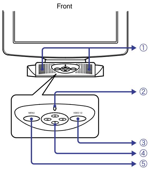
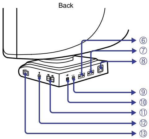
① Speakers
The volume control is performed with the On Screen Display. Press the / Buttons and then the Menu Button continuously when the Menu is not displayed.
② Power Indicator
③ Input Select Button (VIDEO 1/2)
Select eitherVIDEO IN 1 or 2 for the signal input when both of the signal inputs are connected to a signal source. SwitchVIDEO IN 1 and 2 whenever pressing Input Select Button for 3-4 seconds.
NOTE
When only one of the two signal inputs is connected to the signal source, the one connected is automatically selected. Input Select Button is not available if there is no signal input from the selected connector or during the power management mode.

Four Directional Button
⑤ Menu Button (MENU)
D-sub mini 15pin Connector (VIDEO IN 1)
⑦ D-sub mini 15pin Connector (VIDEO IN 2)
⑧ AC Connector (AC IN)
⑨ Audio Connector (AUDIO IN)
USB-UP
Connect with a USB compliant computer by the USB Cable attached to the monitor.
USB-DOWN
Connect any cables from USB compliant peripherals such as mouse, keyboard, etc.
12 Headphone Connector
⑬ Power Switch (POWER)
CONNECTING YOUR MONITOR
① Ensure that both the computer and the monitor are switched off.
② Connect the computer to the monitor with the signal cable. (See page 17 for CONNECTOR PIN ASSIGNMENT.)
③ Connect the monitor to the audio equipment with the Audio Cable when using the audio features.
④ Connect the monitor to the USB compliant computer with the USB Cable when using the USB hub features.
⑤ Connect the Power Cable to the monitor first and then to the power supply.
NOTE
- The signal cables used for the connection vary by the type of computers you use. An incorrect connection may cause serious damage to both the monitor and the computer. The cable supplied with the monitor is for a standard 15 pin D-Sub connector. If a special cable is required please contact your local iiyama dealer or regional iiyama office.
■ For connection to Macintosh computers, contact your local iiyama dealer or regional iiyama office for a suitable adaptor.
Make sure you tighten the finger screws at each end of the signal cable.
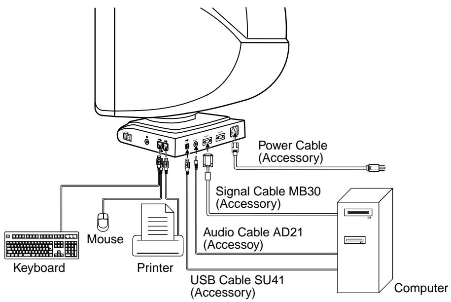
[Example of Connection]
The iiyama Vision Master has been preset at the factory with the signal timings listed on page 17 in PRESET MODES to create the best picture. If an incorrect picture appears during the operation, adjust the image by following the procedure below to get the desired picture.
After selecting an item in the Main Menu, the adjustments and settings are made in the Sub-Menu.
① Main Menu appears on the screen when you press the Menu Button.
For example, to adjust the horizontal screen size, select (Screen Control) on the Main Menu by using the / Buttons. The Sub-Menus appears when you press the Menu Button.

③ Select (H-Size) on the Sub-Menus by using the / Buttons. An adjustment scale will turn white when you press the Menu Button. Use the / Buttons to adjust the horizontal screen size. The vertical screen size adjustment can be also made on this screen by using the / Buttons. See ADJUSTMENT MENU CONTENTS on next pages for further information.
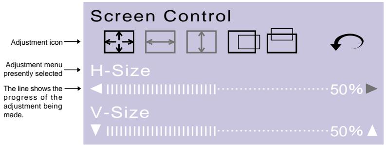
NOTE
The On Screen Display disappears in optional setting seconds after you stop pressing the buttons while performing an adjustment. (See page 11 for OSD Off Timer.)
- Adjustments for Size, Position, Pin-Cushion and Trapezoid are saved for each signal timing. Except for these adjustments, all other adjustments such as Color, Parallelogram, Convergence, Moire, and Landing have only one setting which applies to all signal timings.
Direct
You can skip the Menu pages and display an adjustment scale directly by using the following button operations.
- Volume Control: Press the / Buttons and then the Menu Button continuously when the Menu is not displayed.
- Contrast/Brightness: Press the / Buttons when the Menu is not displayed.
- OPQ: Press the / Buttons when the Menu is not displayed.
NOTE
SWITCHING CONTRAST/BRIGHTNESS AND VOLUME CONTROL
To switch between Contrast/Brightness and Volume Control, press the Menu Button within 2 seconds after pressing the Four Directional Button during the direct adjustments above.
The On Screen Display disappears approx. 3 seconds after you stop pressing the buttons while performing the direct adjustment, irrespective of OSD Off Timer setting. (See page 11 for OSD Off Timer.)
| Main Menu | Sub-Menu | Problem / Option | Button to Press |
| NOTE | Volume Control | Direct | Too soft Too loud |
| Only available on Direct adjustment. | |||
| Color Control | Contrast | Direct | Too dull Too intense |
| Brightness | Direct | Too dark Too bright | |
| COLOR | Color Temp. | Reddish white Bluish white | |
| NOTE | Color temperature is adjustable sRGB and between approximately 10000K and 4500K. The factory preset is 9300K. sRGB Procedure ■ To access the sRGB mode, select the Color Temp. function and select 10000K by pushing the button. Hold down the button & sRGB function will be activated. When this mode is activated the color temperature is approximately 6500K. ■ To deactivate the sRGB mode, push the button while the Color Temp. is selected. NOTE | ■ sRGB is an international standard which defines and unifies the difference of color appearance between equipment. ■ You can not adjust the Contrast, Brightness, OPQ and Gamma Correction during sRGB mode because those settings are locked. | |
| Return to Menu | Return to Main Menu. | ||
| ←→ | Zoom | Too small | ▲ ▲ |
| Too large | ▲ ▲ | ||
| Screen Control | H-Size | Too small | ▲ ▲ |
| Too large | ▲ ▲ | ||
| V-Size | Too small | ▲ ▲ | |
| Too large | ▲ ▼ | ||
| H-Position | Too far to the left | ▲ ▲ | |
| Too far to the right | ▲ ▲ | ||
| V-Position | Too low | ▲ ▲ | |
| Too high | ▲ ▼ | ||
| Return to Menu | Return to Main Menu. | ||
| Shape | Pin-Cushion | To correct distortion | ▲ ▲ |
| Trapezoid | To correct distortion | ▲ ▲ | |
| Parallelogram | To correct distortion | ▲ ▲ | |
| Pin-Balance | To correct distortion | ▲ ▲ | |
| Tilt | To correct tilt | ▲ ▲ | |
| Return to Menu | Return to Main Menu. | ||
| Main Menu | Sub-Menu | Problem / Option | Button to Press | |
| Picture Quality | RGB H-Convergence | To correct misconvergence for vertical lines | ▲ ▲ | |
| R G V-Convergence | To correct misconvergence for horizontal lines | ▲ ▲ | ||
| H Moire | To correct vertical wavy lines | ▲ ▲ | ||
| NOTE Moiré is the result of interference between the phosphor layout and the video signal. By changing the horizontal and vertical size, the moiré can be reduced. You may find the moiré more noticeable depending on the Desktop Pattern you select. In this case, change the desktop pattern. If moiré is still noticeable, use this function to reduce the effect. The picture may shake if extreme moiré correction is performed. | ||||
| VIDEO OPQ Direct | Text | Word processor, spreadsheet, text and a like | ||
| Picture | Still picture | |||
| Movie | Moving picture (DVD / TV) | |||
| NOTE See page 8 for Direct adjustment. | ||||
| RGB Gamma Correction | Midtone color is too dark | ▲ ▲ | ||
| Midtone color is too bright | ▲ ▲ | |||
| Degauss NOTE Degauss should not be repeated continuously. Wait at least 30 minutes between degaussing operations. While degaussing, the picture shakes and a low sound occurs but this does not indicate a problem, it is normal. | Every time the monitor is switched on, the monitor is automatically degaussed. But occasionally the colors change when moving or swiveling the monitor. In this case, first select Degauss. If the problem persists, perform the Landing adjustments. | |||
| Return to Menu | Return to Main Menu. | |||
| Main Menu | Sub-Menus | Problem / Option | Button to Press | |
| Landing | Top-Left | To correct discoloration | ||
| Top-Right | To correct discoloration | |||
| Bottom-Left | To correct discoloration | |||
| Bottom-Right | To correct discoloration | |||
| Return to Menu | Return to Main Menu. | |||
| FUNC | OSD | OSD H-Position | Too far to the left | ▲ ▲ |
| Too far to the right | ▲ ▲ | |||
| OSD | OSD V-Position | Too low | ▲ ▲ | |
| Too high | ▲ ▲ | |||
| OSD Off Timer | 3 5 15 30 45 secYou can set the OSD display time to anyone of the above 5 settings. | |||
| Language | English | English | ||
| Deutsch | German | |||
| Français | French | |||
| Nederlands | Dutch | |||
| Svenska | Swedish | |||
| Japanese | Japanese | |||
| Lockout | On | All adjustment items except this functionare locked out. | ||
| Off | Lockout is canceled. | |||
| Main Menu | Sub-Menu | Option | ||
| FUNC Function | Save Recall | Auto | Any changes are automatically saved in the memory when the On Screen Display disappears. | |
| NOTE Turning off the power should be avoided while using the Menu. | ||||
| Reset | Factory-preset data is restored. | |||
| NOTE Performing this operation resets any adjustment data made by the user to the factory-preset frequencies. The following settings made by the user for signals other than the factory-preset timings remain unchanged.H-Size V-Size Pin-Cushion H-Position V-Position Trapezoid | ||||
| Return to Menu | Return to Main Menu. | |||
| Help | Help | On | Every time you select the sub-menu icon, the online balloon help appears to indicate the menu contents or adjustment procedure. | |
| Off | The online balloon help is off. | |||
| Information | The model name, the serial number and the current horizontal scan frequency and vertical refresh rate is displayed. | |||
| Return to Menu | Return to Main Menu. | |||
POWER MANAGEMENT FEATURE
The power management feature of this product complies with every power saving requirement of ENERGY STAR® and VESA DPMS. When activated, it automatically reduces unnecessary power consumption of the monitor when your computer is not in use.
To use the feature, the monitor needs to be connected to a VESA DPMS compliant computer. There is a power management step the monitor takes as described below. The power management function, including any timer settings is configured by the operating system. Check your operating system manual for information on how this can be configured.
Power Management Mode
When the H-sync signal / V-sync signal / H and V sync signals from the computer are off, the monitor enters into Power Management Mode which reduces the power consumption to less than 3W. The screen becomes dark, and the power indicator turns to orange. From Power Management Mode, the image reappears in 10 seconds when either the keyboard or the mouse are touched again.
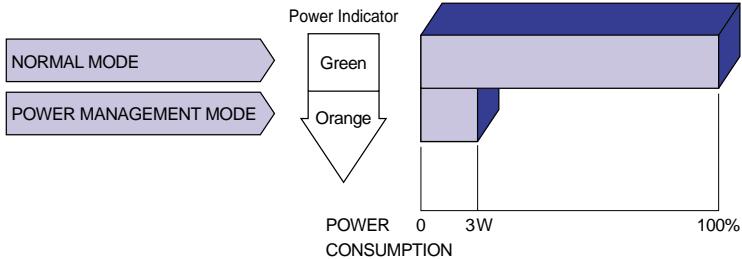
NOTE
Even when using the power management mode, the monitor consumes electricity. Turn off the Power Switch whenever the monitor is not used, during the night and weekends, to avoid unnecessary power consumption.
It is possible that the video signal from the computer may be on while the H or V sync signal is missing. In this instance, the POWER MANAGEMENT feature may not work properly.
If two separate computers are connected to the monitor, one to the VIDEO IN 1 input connector and the other to theVIDEO IN 2 input connector, the POWER MANAGEMENT feature will work only if both computers meet the conditions described above.
SELF-DIAGNOSIS FUNCTION
The monitor has a self-diagnosis function. The monitor diagnoses itself automatically when the picture does not appear and the power indicator is green or orange because of the failure of computer or monitor.
Procedure
① Disconnect the signal cable of the computer or turn OFF the computer.
② Turn ON the monitor.
Diagnosis
① A color bar picture is displayed:
The monitor is working normally. Check the computer.
② A color bar picture is not displayed:
The monitor may be damaged. Contact your dealer or iiyama service center.
TROUBLE SHOOTING
If the monitor fails to operate correctly, please follow the steps below for a possible solution.
- Perform the adjustments described in OPERATING THE MONITOR, depending on the problem you have.
- Consult the following charts if you cannot find an appropriate adjustment item in OPERATING THE MONITOR or if the problem persists.
- If you are experiencing a problem which is not described below or you cannot correct the problem, discontinue using the monitor and contact your dealer or iiyama service center for further assistance.
Problem
Check
① The picture does not appear.
(Power indicator does not light up.)
The Power Cable is firmly seated in the socket.
The Power Switch is turned ON.
The AC socket is live. Please check with another piece of equipment.
(Power indicator is green.)
See page 13 for SELF-DIAGNOSIS FUNCTION.
□ If the blank screen saver is in active mode, touch the keyboard or the mouse.
- Increase the Contrast and/or Brightness.
The computer is ON.
The Signal Cable is properly connected.
The signal timing of the computer is within the specification of the monitor.
(Power indicator is orange.)
See page 13 for SELF-DIAGNOSIS FUNCTION.
□ If the monitor is in power management mode, touch the keyboard or the mouse.
The computer is ON.
The Signal Cable is properly connected.
The signal timing of the computer is within the specification of the monitor.
(2) The screen is not synchronized.
The Signal Cable is properly connected.
The signal timing of the computer is within the specification of the monitor.
The video output level of the computer is within the specification of the monitor.
(3) The screen position is not in the center.
The signal timing of the computer is within the specification of the monitor.
(4) The screen is too bright or too dark.
The video output level of the computer is within the specification of the monitor.
The screen may be too bright due to the video output level difference of the computer. In this case, adjust the Contrast.
(5) The screen is shaking.
- Check if there are any sources of strong magnetic fields such as TV, speakers, etc. nearby.
If yes, remove them from the area of the monitor or change the position/ direction of the monitor to avoid magnetic field interference.
The power voltage is within the specification of the monitor.
The signal timing of the computer is within the specification of the monitor.
Moiré correction is working properly.
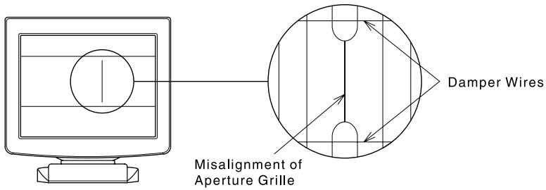
Misalignment of Aperture Grille
Due to the nature of the Diamondtron M^2 /NF -CRT, in rare cases, a misalignment of the aperture grille may happen by the shock or vibration caused during transportation. If a black vertical line appears on the screen, apply a light shock to the side of the monitor with your hand. If the problem persists, follow the procedure below.
① Display a full white picture and inspect the problem area.
② Display a high-white picture that covers the problem area to shoot a strong electron beam. Leave it for a while, until the problem disappears.
Damper Wires
The two faint horizontal lines that may be visible on the screen are actually the shadows of steel wires called Damper Wires. All Diamondtron M^2 /NF -CRT based monitors have these wires for structural reasons.
SPECIFICATIONS
| CRT | 19" (18.0" / 46cm viewable), Aperture Grille pitch Center: 0.25mm, Edges: 0.27mm, 90 degree deflection, Short persistence phosphor, Anti-reflection & Anti-static coating HM903DT: Diamondtron M²-CRT A902MT-v: Diamondtron NF-CRT |
| Sync Frequency | Horizontal: 30.0-130.0kHz, Vertical: 50-200Hz |
| Video Bandwidth | 345MHz dot clock |
| Recommended Resolution | 1280 × 1024 at 85Hz |
| Input Connectors | D-Sub mini 15pin × 2 |
| Plug & Play | VESA DDC2BTM |
| Input Sync Signal | Separate sync: TTL, Positive or Negative Composite sync*: TTL, Positive or Negative Sync on green*: 0.3Vp-p, Negative |
| Input Video Signal | Analog: 0.7Vp-p (Standard), 75Ω, Positive |
| Number of Signal Storage | Factory-presets: 7, User defined settings: 9 maximum |
| Input Audio Connector | Ø 3.5mm mini jack (Stereo) |
| Input Audio Signal | 0.7Vrms maximum |
| Speakers | 1W × 2 (Stereo speakers) |
| Headphone Connector | Ø 3.5mm mini jack (Stereo) |
| Standard Screen Size | 360mm W × 270mm H / 14.2"W × 10.6"H |
| USB Standard Connectors | Rev. 1.1 compliance Self-powered hub Upstream: Series B, Downstream: Series A |
| Number of USB Ports | 1 Upstream (For computer), 4 Downstream (For peripherals) |
| Power Source Power Consumption | 100-230VAC, 50/60Hz, 1.55-0.68A 145W maximum in normal use Power management mode: 3W maximum*2 |
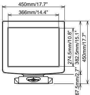
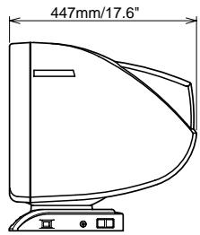
| Dimensions, Net Weight | 450 × 450 × 447mm / 17.7 × 17.7 × 17.6" (W × H × D), 24kg / 52.9lbs |
| Tilt-Swivel Angle | Right / Left: 45 degrees each, Up: 11 degrees, Forward: 5 degrees |
| Environmental Considerations | Operating: Temperature 0 to 35°C / 32 to 95°F Humidity 10 to 80% (No condensation) Storage: Temperature -20 to 60°C / -4 to 140°F Humidity 5 to 90% (No condensation) |
| Approvals | TCO '99, CE, TÜV-GS / MPR III (prEN50279) / ISO 9241-3/ISO 9241-7/ ISO 9241-8, PTB, FCC-B, UL/C-UL, DHHS, Department of Health (Canada) |
NOTE
1 The picture may not be displayed normally depending on the type of signal of a computer system.
2 Condition: USB peripherals or audio equipment are not connected.
The following chart indicates the Factory Preset Modes.
| VESA Timing Name | Horizontal Frequency | Vertical Frequency | Sync Polarity | |||
| H | V | |||||
| 1 | 640×480 | @60Hz | 31.47kHz | 59.9Hz | Negative | Negative |
| 2 | 640×480 | @85Hz | 43.27kHz | 85.0Hz | Negative | Negative |
| 3 | 800×600 | @85Hz | 53.67kHz | 85.1Hz | Positive | Positive |
| 4 | 1024×768 | @85Hz | 68.68kHz | 85.0Hz | Positive | Positive |
| 5 | 1280×1024 | @85Hz | 91.15kHz | 85.0Hz | Positive | Positive |
| 6 | 1600×1200 | @85Hz | 106.25kHz | 85.0Hz | Positive | Positive |
| 7 | 1920×1440 | @85Hz | 128.52kHz | 85.0Hz | Positive | Positive |
NOTE
Additional adjustments may be required to the factory-presets, because the signal timings vary depending on the type of graphics board you use.
CONNECTOR PIN ASSIGNMENT
| Pin | Input Signal | Pin | Input Signal |
| 1 | Red video | 9 | |
| 2 | Green video / Sync on green | 10 | Ground |
| 3 | Blue video | 11 | Ground |
| 4 | 12 | Data line (SDA) * | |
| 5 | 13 | H-Sync / HV-Sync | |
| 6 | Red video ground | 14 | V-Sync |
| 7 | Green video ground | 15 | Clock line (SCL) * |
| 8 | Blue video ground | * Compliant to VESA DDC. | |