
T8132 - Thermostat HONEYWELL - Free user manual and instructions
Find the device manual for free T8132 HONEYWELL in PDF.

| Product Type | Programmable Thermostat |
| Brand | Honeywell |
| Model | T8132 |
| Power Supply | 2 AA alkaline batteries (Energizer® recommended) |
| Display | LCD with low battery indicator (BAT LO) |
| Programming | 4 periods per day (WAKE, LEAVE, RETURN, SLEEP) for weekdays and weekends |
| Temperature Range | From 7 °C to 31 °C (45 °F to 88 °F) for heating and cooling |
| Maximum number of wires | 5 wires (compatible with 2, 3, 4, or 5 wires) |
| System Compatibility | Gas (pilot or electronic ignition), gas/oil boilers, electric, air conditioner |
| Not compatible | Millivolt systems, 120/240 V baseboards, heat pumps, multi-stage, steam |
| Fan switch | Position F (default) for most systems, E for electric heating |
| Cycle adjustment | Screws A and B on the back of the thermostat to adjust run time |
| Special functions | Temporary temperature override, hold, program check |
| Compressor protection | 5-minute delay in cooling mode |
| Warranty | 1 year limited (excluding batteries) |
| Customer service | 1-800-468-1502 (Monday-Friday, 7am-5:30pm) |
| Maintenance | Clean with a damp cloth; do not use abrasive cleaners |
| Installation | Requires a level; seal the wall hole to prevent drafts |
Frequently Asked Questions - T8132 HONEYWELL
User questions about T8132 HONEYWELL
0 question about this device. Answer the ones you know or ask your own.
Ask a new question about this device
Download the instructions for your Thermostat in PDF format for free! Find your manual T8132 - HONEYWELL and take your electronic device back in hand. On this page are published all the documents necessary for the use of your device. T8132 by HONEYWELL.
USER MANUAL T8132 HONEYWELL
PROGRAMMING AND INSTALLATION INSTRUCTIONS
Rev. 9-92 • Form Number 69-0740B—1
Weekday/Weekend
Programmable Heat and/or Cool
Thermostat and Mounting Plate
Model T8132
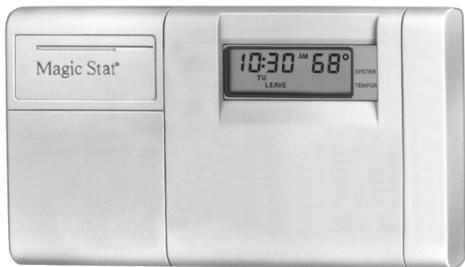
Welcome to the world of comfort and energy savings with your new Honeywell MagicStat™ programmable thermostat.
Your new thermostat will automatically control the temperature in your home, keeping you comfortable while saving energy when programmed according to the instructions in this manual.
Any questions concerning the application of this thermostat should be directed to Honeywell Customer Assistance at 1-800-468-1502, Monday-Friday 7:00 a.m.-5:30 p.m., Central time.
Table Of Contents
STEP 1 Prepare For Installation 2
STEP 2 Remove Old Thermostat 4
STEP 3 Install The Batteries 6
STEP 4 Program The Thermostat 8
STEP 5 Adjust Fan Operation Switch, as Required 16
STEP 6 Adjust System On-Length as Required 16
STEP 7 Mount Thermostat Mounting Plate 18
STEP 8 Wire Thermostat Terminals 20
STEP 9 Mount The Thermostat 24
STEP 10 Check Thermostat Operation After Programming and Installing 25
STEP 11 Set The Fan and System Switches 27
Troubleshooting Guide 28
Limited One-Year Warranty 33
Prepare For Installation
Check Table 1 to make sure this thermostat is compatible with your system. If not, return to retailer. For more information, call Honeywell Customer Assistance, toll-free 1-800-468-1502.
TABLE 1-COMPATIBILITY CHART.
| System Type | Compatible With CT3200 |
| Gas-Standing Pilot | Yes |
| Gas-Electronic Ignition | Yes |
| Gas-Fired Boilers | Yes |
| Gas-Millivolt | No |
| Oil-Fired Boilers | Yes |
| Oil-Fired Furnace | Yes |
| Electric Furnace | Yes |
| Electric Air Conditioning | Yes |
| Baseboard Electric (120/240 Line Volt) | No |
| Heat Pumps/Multistage Equipment | No |
Not compatible with any 120/240 volt circuit.
Will not work efficiently on steam or gravity systems.
Compatible with 2-wire Honeywell zone valves. Isolating relay required for 3-wire thermostats for zone valves. Not compatible with 2-wire White-Rodgers #1361 valves.
Acquire tools and items as needed (below). Also purchase two AA alkaline batteries; we recommend Energizer batteries
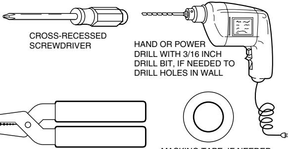
WIRE CUTTER/STRIPPER OR SHARP KNIFE, IF NEEDED TO STRIP WIRES
MASKING TAPE, IF NEEDED TO LABEL WIRES AS THEY ARE DISCONNECTED FROM OLD THERMOSTAT
SPIRIT LEVEL, IF NEEDED TO LEVEL THERMOSTAT FOR APPEARANCE
M 878
Remove Old Thermostat
Test to make certain that your heating and cooling systems are working properly. If either does not work, contact your local heating/air conditioning dealer. To avoid compressor damage, do not operate the cooling system when outdoor temperature is below 10^ C [50°F].
TURNOFFPOWERto system at the furnace,or at the fuse/circuit breaker panel.
- Carefully unpack your new thermostat and mounting plate; save package of screws, instructions and receipt.
- Remove cover from old thermostat. If it does not snap off when pulled firmly from the bottom, check for a screw used to lock on the cover.
Loosen screws holding thermostat to
subbase, wallplate or wall, and lift away.
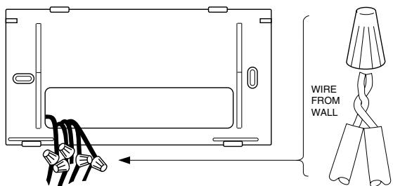
- Disconnect wires from old thermostat or subbase. As you disconnect each wire, use masking tape to label it with the old terminal designation. If there are only two wires, they do not need to be labeled. Keep the wires from falling back into the wall by wrapping them around a pencil, as shown.
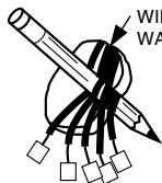
WIRES THROUGH WALL OPENING
M5136
One or two extra wires?
If you are replacing a Honeywell Chronotherm thermostat, you may find one or two wires that go to the C or C1 clock terminals on the Chronotherm thermostat wiring wallplate. Do not allow them to touch, or you may damage your transformer. Disconnect the wires and wrap them separately, using electrical tape. Do not wrap them together. Place the wires where they will not interfere with the operation of the new thermostat. Record the colors and terminal designation labels of the remaining wires.
Six or more wires?
If there are six or more wires (excluding clock wires attached to terminals), you most likely have a variation of a heat pump or multistage system. The thermostat is
not compatible with such systems so return the product to the place of purchase. If you would like information about which programmable thermostats will work with your system, call Honeywell Customer Assistance at 1-800-468-1502.
Three thermostat wires?
If you have three wires for heating only and can operate the fan using the fan ON switch, this thermostat will work with your system. However, some hot water (zoned) heating systems have three thermostat wires. The thermostat will not work without installing an isolating relay on these systems. Call Honeywell Customer Assistance at 1-800-468-1502 for details.
STEP 3 Install The Batteries
IMPORTANT
Batteries must be installed for programming and operation of the thermostat and heating/ cooling system.
Purchase two AA alkaline batteries; nonalkaline batteries will not last as long. We recommend Energizer batteries.
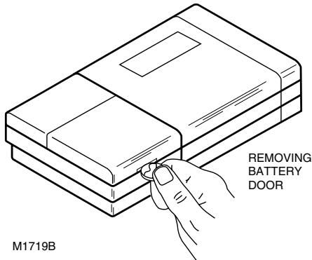
Make sure the thermostat is set in OFF position.
Use a coin to remove battery door.
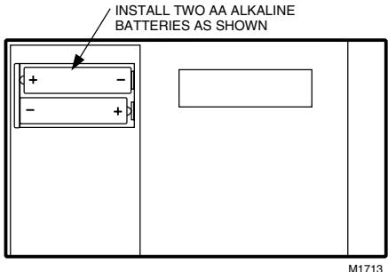
Install the fresh batteries as shown, making sure positive and negative terminals are oriented correctly.
Replace battery door.
As the batteries are running low, a "bAt Lo" indicator will flash for 1-2 months before batteries run out completely. Replace the batteries as soon as possible after the indicator starts flashing. If you do not replace the batteries sometime during the flashing "bAt Lo" indicator, the indicator will eventually stop flashing. "bAt Lo"
will stay on without flashing to indicate the thermostat and heating/cooling system have stopped working when the batteries are almost completely dead.
After the batteries are completely dead, the "bAt Lo" indicator will disappear, leaving a completely blank display.
Press down on left ends of batteries to remove. If you insert the new batteries within 20-30
seconds of removing the old ones, you will not have to reprogram the thermostat. However, if the display is blank, the batteries are dead or incorrectly installed. In this case, you will have to reprogram. See pages 12-13 to reprogram.
IMPORTANT
Although the thermostat has a low battery indicator, replace the batteries once a year to prevent the thermostat and heating/cooling system from shutting down due to lack of battery power.
When leaving home for longer than a month, I have a precaution, change batteries before you have to prevent system from shutting down due to lack of battery power.
Program The Thermostat
After the batteries are installed, the thermostat can be easily programmed in your hand, before it is installed on the wall.
If you would prefer to program the thermostat after it is installed on the wall, skip to page 16, and return later to this programming section.
The following personal programming chart (pages 10-11) may be helpful for planning your program schedule of time and temperature settings for various times of the day.
Four time periods are available during weekdays — “WAKE”, “LEAVE”, “RETURN”, and “SLEEP”. These periods can be seen individually on the display as you press the SET SCHEDULE key.
"WAKE" is the time period you want the house at a comfortable temperature after you get up, while you get ready for work or school. (This will be a higher temperature during heating season, or a lower temperature during cooling season.)
"LEAVE" is the time period you can set for an energy-saving temperature while you are away at work or school. (This will be a lower temperature during heating season, or a higher temperature during cooling season.) "RETURN" is the time period you want the house at a comfortable temperature for activities before bedtime. (Again, higher heat or lower cool.)
"SLEEP" is the time period you can set for an energy-saving temperature while you are
sleeping. (Again, lower heat or higher cool. Although for more comfortable sleeping, some people choose not to raise the cool temperature during the night.)
You will set one schedule for weekdays and another for weekends, since your requirements will probably be different for each. Also, during weekends only the "WAKE" and "SLEEP" time periods are available.
Fill in the times and temperatures you desire for weekdays and weekends. If you decide not to program the thermostat, it will automatically control heating at 20^ C [68°F], and cooling at
26^ [78° F], 24 hours a day. Also, you do not need to enter a time and temperature program for all periods if your schedule does not require it. For example, a house that is occupied during weekdays would not require programs for "LEAVE" and "RETURN".
When pressing the keys, use the ball of your finger or a soft pencil eraser. Use of sharp fingernails or pencil points may damage the keypad.
If at any time during programming you make an error, just press the RUN PROGRAM key, and continue again at the step where you left off.
Personal Programming Chart
HEATING PROGRAM
Weekdays
WAKE
LEAVE
RETURN
SLEEP
Weekends
WAKE
SLEEP
Start Time
Heating Temperature

If you decide not to enter weekend programs, the WAKE and SLEEP from the weekday program will copy to the weekend schedule.
The temperatures cannot be set any higher than 31^ [88° F] or any lower than 7^ [45° F].
COOLING PROGRAM
Weekdays
WAKE
LEAVE
RETURN
SLEEP
Start Time
Cooling Temperature

Weekends
WAKE
SLEEP


If you decide not to enter weekend programs, the WAKE and SLEEP from the weekday program will copy to the weekend schedule.

The temperatures cannot be set any higher than 31^ [88° F] or any lower than 7^ [45° F].
NOTE: If you decide not to program the thermostat, it will automatically control heating at 20^ C [68°F], and cooling at 26^ C [78°F], 24 hours a day.
This guide can be used for programming your new thermostat.
NOTE: Batteries are required for operation and programming. When inserting batteries, set system switch to OFF. Remove battery door (on thermostat left side) using a coin at the bottom. Follow instructions on pages 6-7.
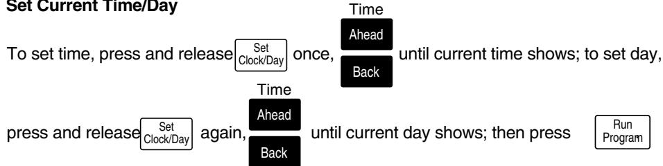
Set Current Time/Day
Heating Program
With system switch at HEAT, press and release appear on display.
Set Schedule
once. "WAKE", Mon-Fri and "SET"
Mon-Fri. Repeat sequence for "LEAVE", "RETURN", "SLEEP".
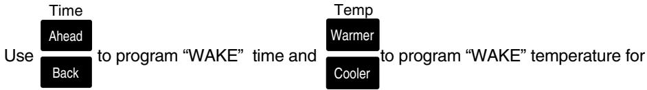
Press Set until "WAKE", "SA SU" and "SET" appear on display. Use Ahead to program Temp Back
"WAKE" time and Warmer to program "WAKE" temperature for Sat-Sun. Repeat sequence for "SLEEP". cooler
Cooling Program
With system switch at COOL, follow same instructions as for Heating Program.
After programming, adjust fan and system switches as desired. Press and release the program.
Run Program start
A quick guide for operating or making changes follows:
NOTE: System switch must be set to Heat or Cool to perform the following.
Temporarily Change temperature for current period only
Temp
Warmer
Cooler
will cancel itself at next scheduled change, or to cancel sooner press
Run Program
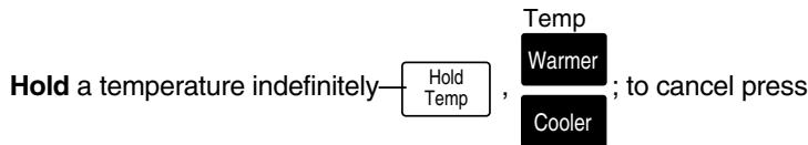
Run Program
Check Current Temperature Setting— Run Program (If using TEMPORARILY CHANGE
or HOLD, pressing this will cancel your change.)
Permanently Change a program—Repeat steps under Heating Program or Cooling Program (page 12-13) as applicable.
Return to normal program or start program Run Program
Questions?
Call Honeywell
Customer Assistance
1-800-468-1502.
STEP5
Adjust Fan Operation Switch, As Required
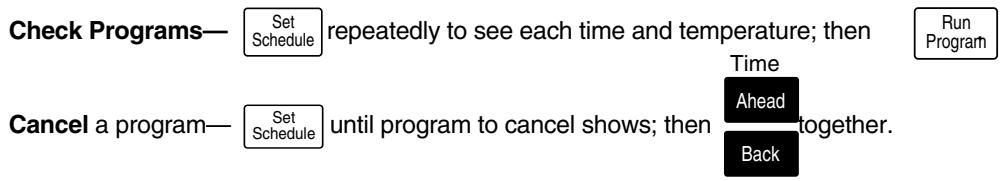
The thermostat fan operation switch, labeled FUEL SWITCH (see figure on page 17) is factory-set in the "F" position. This is the correct setting for most systems. If your system is an electric heat
system, set the switch to "E". The "E" setting will allow the fan to turn on immediately with the heating or cooling in a system where the "G" terminal is connected.
STEP 6
Adjust System On-Length As Required
The thermostat on-length is factory-set for a warm air, gas or oil heating system. If you are installing it on another type of system, the on-length must be adjusted accordingly by setting screws A and B on the back of the thermostat, using the heating system table in the figure
(page 17) as a guide. The on-length should be optimized according to the type of system to minimize room temperature swings. Setting the screw "out one turn" means turning the screw approximately 360^ , or about one complete turn.
In the rare event that you want a longer on-length, you may readjust the screws as follows:
| If on-length screws A,B are adjusted to match this system: | For longer on-length, readjust screws A,B to match this system: |
| electric furnace | warm air furnace |
| warm air furnace | hot water boiler |
NOTE: This thermostat does not have a setting for steam/gravity air. Cycles would not be long enough for accurate temperature control.
IMPORTANT
When using a high efficiency furnace such as a 90% or greater AFUE (Average Fuel Utilization Efficiency) unit, adjust screw A out one turn and screw B in.
THERMOSTAT BACK

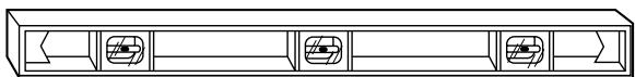
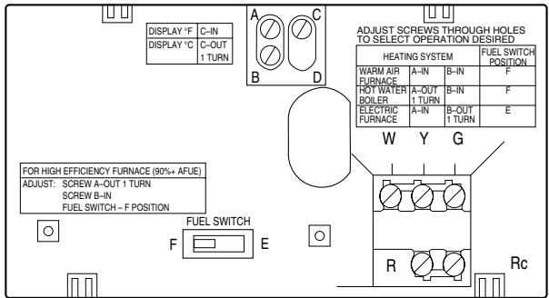
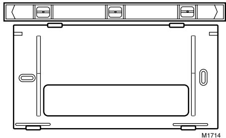
Mount Thermostat Mounting Plate
Position mounting plate on wall. Use spirit level to make sure mounting plate is level. Use a pencil to mark the two mounting holes.
-
Remove mounting plate from wall, and drill 3/16'' holes in wall (if drywall) as marked. For firmer material such as plaster or wood, drill 7/32'' holes. Gently tap anchors (provided) into drilled holes until flush with the wall.
-
Reposition mounting plate over holes, pulling wires through wiring opening. Loosely insert two mounting screws into holes.
Level for appearance only; thermostat will function properly even when not level. Tighten mounting screws.
SPIRIT LEVEL
STEP8
Wire Thermostat Terminals
NOTE: All wiring must comply with local codes and ordinances. If unsure about household wiring procedures, call your local heating/air conditioning contractor.
METHOD TO INCREASE WIRE LENGTH
M1715A
Refer to masking tape labels you placed on wires when you removed your old thermostat.
- Match the letter of your old thermostat wire with the terminal of the corresponding letter on the back of your new thermostat. Refer to figures on pages 22-23 and Table 2 for typical wire colors for easy matching. Hold the thermostat as shown to minimize need for wire extenders. If wires are still
WIRE NUT SIZE
FOR TWO
18-GAUGE WIRES
6-in. [152 mm] OF
18-GAUGE
THERMOSTAT
WIRE. MATCH
INSULATION
COLORS OR
MARK WIRE ENDS.
too short, use wire connectors (purchase locally) to extend wires. See figure (left) for guidelines on using wire extenders.
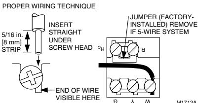
In 5-wire installations only, be sure to remove the factory-installed jumper connecting terminals R and Rc.
TABLE 2-TYPICAL WIRE COLORS AND FUNCTIONS.
| THERMOSTAT TERMINAL | CONNECT TO WIRE COLORa | FUNCTION |
| G | Green | Fan |
| Y | Yellow | Cooling |
| W | White | Heating |
| Rc | Blue | Air Cond. Power |
| R | Red | Furnace Power |
a Wire colors are typical; verify at heating/cooling equipment connection.
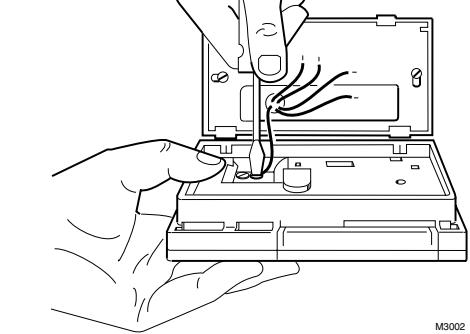
- Loosen the terminal screws and slip each wire beneath its matching terminal. See figure (lower right) for wire insertion technique. Tighten terminals securely.
Plug the hole in the wall with insulation to help prevent drafts from adversely affecting thermostat operation.
M3002
POWER SUPPLY. PROVIDE DISCONNECT MEANS AND
OVERLOAD PROTECTION AS REQUIRED.
M1710A
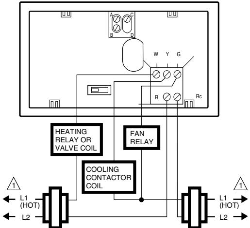
5-WIRE HEAT/COOL (JUMPER REMOVED)

POWER SUPPLY. PROVIDE DISCONNECT MEANS AND
OVERLOAD PROTECTION AS REQUIRED.
M1711A
A. ENGAGE TABS AT TOP OF THERMOSTAT AND MOUNTING PLATE.
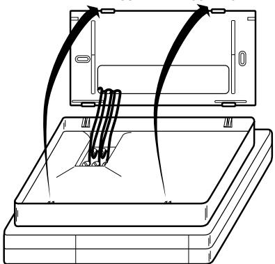
NOTE: To remove thermostat from wall, first pull out at bottom of thermostat, removing top last.
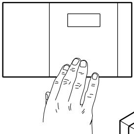
B. PRESS LOWER EDGE OF CASE TO LATCH.
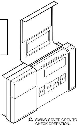
Check Thermostat Operation After
STEP10
Programming And Installing
HEATING
Do NOT check heating system operation by jumpering thermostat terminals at the primary control, such as the gas valve, zone valve, oil burner control. This will damage the thermostat.

Move the system switch to HEAT and the fan switch to AUTO.
Press key until the setting is about 6^ C [10^ F] above room temperature. Heating should start and the fan should run after a short delay (immediately if fan operation switch is set in E position).
Press key until setting is about 6^ C [10^ F] below room temperature. The heating equipment should shut off.
COOLING
To avoid possible compressor damage, do not operate the cooling system when outside temperature is below 10^ [50° F]. See compressor manu-facturer's instructions for further information.
NOTE: When cooling setting is changed, thermostat may delay up to five minutes before turning on the air conditioner. This delay protects the compressor.


Move the system switch to COOL and the fan switch to AUTO.
Press key until setting is about 6^ C [10^ F] below room temperature. The cooling equipment and fan should start.
Press key until the setting is about 6^ C [10^ F] above room temperature. The cooling equipment and fan should stop.
Move the system switch to OFF, with the fan switch still at AUTO. The system and fan should be off.
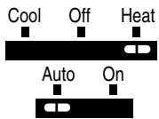
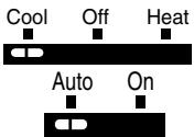
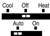
Set The Fan And System Switches
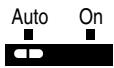
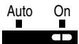
First set the fan switch.
FAN AUTO: Normal setting for most homes. A single-speed fan will turn on automatically with the air conditioner or furnace. A two-speed fan will usually run on high with the air conditioner and on low with the furnace.
FAN ON: The fan runs continuously. Use for improved air circulation during special occasions or for more efficient electronic air cleaning.
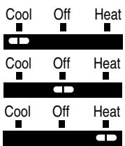
air conditioning system.
OFF: Both the heating and air conditioning systems are off.
HEAT: The thermostat controls your heating system.
Troubleshooting Guide
IF...
Display will not come on.
Temperature display will not go lower than 7^ C [45^ F] or higher than 31^ C [88^ F] during programming.
Temperature change occurs at the wrong times.
Heating will not come on.
THEN...
- Set the system switch to OFF; remove batteries; insert backwards for at least 5 seconds to reset thermostat; replace batteries correctly. Display should come on.
Make sure batteries are fresh and installed correctly.
You have reached the temperature setting limit. The setting range is 7^ to 31^ [45°F to 88°F].
Check the program times for the period in question. Be sure that AM and PM indications are correct. Make sure the current day and time are correct. Reprogram if necessary.
Check that switch on thermostat is set to HEAT.
Check the system fuse or circuit breaker and replace or reset if necessary.
Cooling will not come on.
If display is blank or says "bAt Lo," install fresh batteries.
If temperature setting is higher than current temperature, and SYSTEM ON indicator is lit, contact Honeywell Customer Assistance at 1-800-468-1502.
Check that switch on thermostat is set to COOL.
Check the system fuse or circuit breaker and replace or reset if necessary.
If display is blank or says "bAt Lo," install fresh batteries.
The thermostat has a built-in time delay on cooling. Allow 5 to 10 minutes after changing the setting before the air conditioner starts.
If temperature setting is lower than current temperature, and SYSTEM ON indicator is lit, move system switch from COOL to OFF for 10 minutes. After 10 minutes, return switch to COOL position. If air
Cooling will not come on. (Cont.)
conditioner comes on, compressor may have reached its high limit temperature protection and shut down. If air conditioner does not come on after the 10 minutes and the SYSTEM ON indicator is lit, contact Honeywell Consumer Services at 1-800-468-1502.
The house is too warm or too cool.
If 2- or 4-wire installation, verify that R-Rc jumper is installed.
Press RUN PROGRAM key to check the current temperature setting.
If desired, change the temperature setting. See page 14.
SYSTEM ON indicator is lit, but no heat is coming from the registers.
- Allow time for the furnace to heat up and the fan to come on before checking for heat at the register. Check to make sure system on-length is set correctly according to page 16.)
Furnace or air conditioner cycles too frequently.
Check system setting on back of thermostat.
The system cycle length is too short or too long.
The thermostat's current setting does not match the display temperature.
Readjust according to instructions on pages 16-17.
Check that the wiring hole in the wall behind the wallplate has been plugged with insulation to prevent drafts which might adversely affect thermostat operation.
- Be aware that it is normal for the current setting and display temperature to differ on occasion.
Toll-free Customer Assistance
For all questions concerning this thermostat, please read and follow the instructions. If additional assistance is needed, call Honeywell Customer Assistance toll-free at 1-800-468-1502, Monday-Friday, 7:00 a.m. - 5:30 p.m. Central time.
Before you call, please have the following information available—thermostat model number and date code, kind of heating/cooling system (i.e., hot water, warm air, oil, gas, etc.), number of wires connected to the thermostat.
NOTICE
This equipment is a Class B digital apparatus, which complies with Canadian Radio Interference Regulations, CRC c.1374.
Limited One-Year Warranty
Honeywell warrants this product, excluding battery, to be free from defects in the workmanship or materials, under normal use and service, for a period of one (1) year from the date of purchase by the consumer. If, at any time during the warranty period, the product is defective or malfunctions, Honeywell shall repair or replace it (at Honeywell's option) within a reasonable period of time.
If the product is defective,
(i) return it, with a bill of sale or other dated proof of purchase, to the retailer from which you purchased it, or
(ii) package it carefully, along with proof of purchase (including date of purchase) and a short description of the malfunction, and mail it, postage prepaid, to the following address:
Honeywell Inc.
Return Goods Department
1050 Berkshire Lane
Plymouth, MN 55441-4437
in Canada: Honeywell Limited/Honeywell Limitée
Product Services ON15-FFE
740 Ellesmere Road
Scarborough, Ontario M1P 2V9
This warranty does not cover removal or reinstallation costs. This warranty shall not apply if it is shown by Honeywell that the defect or malfunction was caused by damage which occurred while the product was in the possession of a consumer.
Honeywell's sole responsibility shall be to repair or replace the product within the terms stated above. HONEYWELL SHALL NOT BE LIABLE FOR ANY LOSS OR DAMAGE OF ANY KIND, INCLUDING ANY INCIDENTAL OR CONSEQUENTIAL DAMAGES RESULTING, DIRECTLY OR INDIRECTLY, FROM ANY BREACH OF ANY WARRANTY, EXPRESS OR IMPLIED, OR ANY OTHER FAILURE OF THIS PRODUCT. Some states do not allow the exclusion or limitation of incidental or consequential damages, so this limitation may not apply to you.
THIS WARRANTY IS THE ONLY EXPRESS WARRANTY HONEYWELL MAKES ON THIS PRODUCT. THE DURATION OF ANY IMPLIED WARRANTYIS, INCLUDING THE WARRANTY OF MERCHANTABILITY AND FITNESS FOR A PARTICULAR PURPOSE, IS HEREBY LIMITED TO THE ONE YEAR DURATION OF THIS WARRANTY. Some states do not allow limitations on how long an implied warranty lasts, so the above limitation may not apply to you.
This warranty gives you specific legal rights, and you may have other rights which vary from state to state.
If you have any questions concerning this warranty, please write our Customer Assistance Center, Honeywell Inc., P.O. Box 524, MN27-2164, Minneapolis, MN 55440-0524 or call 1-800-468-1502, Monday-Friday, 7:00 a.m. to 5:30 p.m., Central time. In Canada, write Retail Products ON15-02H, Honeywell Limited/Honeywell Limitée, 740 Ellesmere Road, Scarborough, Ontario M1P 2V9.
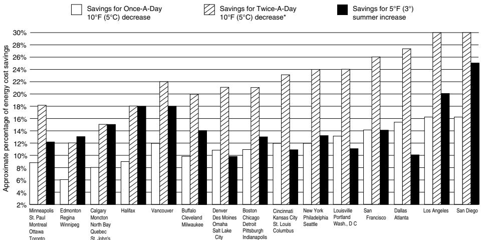
TYPICAL ENERGY SAVINGS FOR REPRESENTATIVE CITIES IN THE U.S. AND CANADA
Thermostat patents pending.
*Based on 10°F (5°C) decrease—(5°F (3°C) decrease gives approximately 55 percent of these savings). M2416A
THERMOSTAT PROGRAMMABLE DE HONEYWELL
MagicStat ^md / T8132
MANUEL DE PROGRAMMATION ET D'INSTALLATION
9-92 • Publication n⁰ 69-0740B—1
Return Goods Department
1050 Berkshire Lane
Plymouth, MN 55441-4437
Au Canada: Honeywell Limited/Honeywell Limitée
Product Services ON15-FFE
740 Ellesmere Road
Scarborough, Ontario M1P 2V9