
Bigdry 4000 Expert M - Washing machine CECOTEC - Free user manual and instructions
Find the device manual for free Bigdry 4000 Expert M CECOTEC in PDF.


User questions about Bigdry 4000 Expert M CECOTEC
0 question about this device. Answer the ones you know or ask your own.
Ask a new question about this device
Download the instructions for your Washing machine in PDF format for free! Find your manual Bigdry 4000 Expert M - CECOTEC and take your electronic device back in hand. On this page are published all the documents necessary for the use of your device. Bigdry 4000 Expert M by CECOTEC.
USER MANUAL Bigdry 4000 Expert M CECOTEC

- Parts and components 40
- Before use 40
- Operation 41
- Cleaning and maintenance 42
- Troubleshooting 42
- Technical specifications 48
- Disposal of old electrical and electronic appliances 49
- Technical support and warranty 49
- Copyright 49
SOMMAIRE
Read these instructions thoroughly before using the appliance. Keep this instruction manual for future reference or new users.
- This appliance can be used by children aged 8 years and above and persons with reduced physical, sensory, or mental capabilities or lack of experience and knowledge if they have been given supervision or instruction concerning use of the appliance in a safe way and understand the hazards involved. Children must not play with the appliance. Cleaning and user maintenance should not be carried out by unsupervised children.
- The appliance shall be installed in accordance with national electrical installation regulations
- This symbol means: CAUTION, risk of fire.
- This symbol means: CAUTION, read the instruction manual before using the appliance.
- i This symbol means: check the instructions for use.
- This symbol means: CAUTION, read the technical manual.
- This appliance is designed for domestic use only and is not intended for bars, restaurants, farmhouses, hotels, motels, and offices.
- Ensure that the mains voltage matches the voltage specified on the appliance rating label and that the plug is earthed.
-
Check the power cable regularly for visible damage. If the cable is damaged, it must be repaired by the official Cecotec Technical Support Service to avoid any type of danger.
-
To avoid electric shocks, do not clean the appliance with water, flammable substances, or other liquids, and do not allow them to enter the appliance.
- Do not immerse the cable, plug, or any non-removable part of the appliance in water or any other liquid or expose electrical connections to water. Make sure your hands are dry before handling the plug or switching on the appliance.
- The appliance must be installed, operated, and stored in a room with a floor area larger than 4 m2 .
- Switch off the appliance immediately in the event of defects or malfunctions.
- Do not use the appliance if the cable or any other part is damaged. In this case, contact the official Cecotec Technical Support Service.
- Do not use insecticides, perfumes, or other flammable substances near the appliance. Do not operate the appliance with odour-producing products.
- Do not install the appliance near heat-generating appliances or flammable and dangerous materials.
- This appliance cannot replace normal ventilation products.
- Make sure the appliance is kept and stored in well-ventilated areas.
- During operation, leave at least 20 cm of free space on the back and sides of the appliance.
- Install the drain piping at a grade that allows condensed water to be drained continuously.
- The appliance must be placed so that the plug is accessible.
- The appliance must be installed in accordance with local national wire and gas regulations.
-
Operate the appliance in places with a temperature range between 5 °C and 35 °C. Operating it outside of this range could cause the appliance not to operate properly.
-
Ensure the filter and cover of the appliance are properly installed before operation.
- Do not sit or stand on the appliance.
- Make sure the tank of the appliance is emptied after each use to ensure proper operation.
- Do not operate the appliance in closed areas such as inside closets. Do not use outdoors.
- Do not insert fingers or other objects in the air inlet or outlet to prevent injuries and product damage.
- Do not twist, bend, pull, or damage the power cable. Protect it from sharp edges and heat sources. Do not allow the cable to touch hot surfaces. Do not let the cable hang over the edge of the surface or worktop.
INSTRUCTIONS DE SÉCURITÉ
- Top panel
- Control panel
- Back housing
- Filter compartment
- Front housing
- Water tank
- Wheels
- Cable
Control panel. Fig. 2
- Power icon
- Settings
- Low/High-speed icon
- Timer icon
- Full Tank icon
NOTE:
The graphics in this manual are schematic representations and may not exactly match the appliance.
The display of the appliance will show:
- Room humidity level (when plugged in).
- Once the humidity level is set, it will display it.
- The time set for automatic switch-off.
- When ambient humidity is lower than 35%, it will show "35".
- When ambient humidity is higher than 95%, it will show "95".
2. BEFORE USE
- This appliance is packaged in a way as to protect it during transport. Take the appliance out of its box and remove all packaging materials. You can keep the original box and other packaging elements in a safe place. This will help you prevent product damage when transporting it in the future. In case the original packaging is disposed of, make sure all packaging materials are recycled accordingly.
- Make sure all parts and components are included and in good conditions. If there is any
piece missing or in bad conditions, contact the official Cecotec Technical Support Service immediately.
- When installing the appliance, ensure a minimum safety distance of 20 cm on each of its sides. Fig. 3
3. OPERATION
- The power indicator light will turn on when the appliance is plugged in,
- regardless of whether the unit is in operation or not.
- Tap the power icon once to start operation. Press it again to stop operation.
- Tap the Low/High-speed icon to enable the fan function. Press the same icon to select between low or high speed.
- Tap the settings icon to set the desired room humidity level. Humidity can be set from 40% to 80%, in 5% intervals.
- Note: after the appliance has been running for some time, if ambient humidity is lower than the set value by 2%, the appliance will stop operation after 3 minutes. If ambient humidity is equal to or higher than the selected humidity by 2%, the appliance will automatically resume operation.
Draining collected water
When the water tank is full, the full-tank indicator light will turn on, the appliance will automatically stop operation, and it will beep 15 times to alert the user that the tank needs to be emptied.
Emptying the water tank
- Lightly press on the sides of the tank with both hands and pull the tank out gently. Fig. 4
- Empty water inside the tank. Fig. 5
- Note: Do not remove the float from the water tank. The Tank Full sensor will stop detecting the water level when the float is removed, so water may leak out of the tank. Fig. 6
- To install the tank back in place, press it firmly into place with both hands. If the tank is not properly installed, the full-tank indicator will turn on and the appliance will not work. Fig. 7
Continuous water drainage. Fig. 8
- The unit features a continuous-drainage port. Using a plastic pipe (with an inner diameter of 10 mm), insert it into drain hole (on intermediate plate), reach out from side of water tank, install it in place, and arrange the drain pipe.
- The water in the tank can be continuously drained out from the continuous port on the unit.
4. CLEANING AND MAINTENANCE
- Turn off and unplug the appliance from the power supply before cleaning or repairing it.
- Use a soft, damp cloth with some neutral cleaning agent to clean the product's outside.
- If the appliance is not going to be used for a long time, pour out the remaining water, thoroughly dry all parts, and store the appliance in a safe and well-ventilated place.
- If the water tank is dirty, wash it with cold or lukewarm water. Do not use detergent, scouring pads, chemically-treated cloths, petrol, benzene, thinner, or other solvents, as these can scratch and damage the tank and cause water leakage.
Cleaning the filter
- Open the filter compartment and remove the filter. Fig. 9
- Run a vacuum cleaner lightly over the surface of the air filter to remove dirt. If the air filter is exceptionally dirty, wash it with warm water and a mild cleanser. Dry thoroughly. Fig. 10
- To attach the air filter, insert it into the grill smoothly, and place the compartment into its right place. Fig. 11
Storage
- Before storing the appliance for a long period of time:
- Empty any water left in the tank.
- Wind the power cable and put it in the water tank.
- Clean the filter edge.
- Store it in a cool and dry place.
5. TROUBLESHOOTING
| Problem | Possible cause | Possible solution |
| The appliance does not work. | Has the power cable been disconnected? | Plug the power cable into the outlet. |
| Is the full-tank indicator light switched on (the tank is full or not installed properly)? | Empty the water in the tank and then reinstall the tank. | |
| Is the temperature of the room above 35 °C or below 5 °C? | The protection device has been activated and the appliance does not work. |
| The dehumidifying function does not work. | Is the filter clogged? | Clean the filter as described in this manual. |
| Is the intake duct or discharge duct obstructed? | Remove the obstruction from the discharge duct or intake duct. | |
| No air is discharged. | Is the filter clogged? | Clean the filter as described in this manual. |
| The appliance makes strange noises during operation. | Is the appliance tilted or unsteady? | Move the appliance to a stable location. |
| Is the filter clogged? | Clean the filter as described in this manual. | |
| The control panel displays “E1”. | The humidity or room temperature sensor does not work. | Contact the official Cecotec Technical Support Service. |
1. Service information
1.1 Area verification
Before starting work on systems containing flammable refrigerants, safety checks are necessary to ensure that the risk of ignition is minimised. Before repairing the cooling system, the following precautions must be observed:
1.2. Work procedure
The work must be carried out in accordance with a controlled procedure to minimise the risk of a flammable vapour or gas being present while the work is being carried out.
1.3. General workspace
All maintenance personnel and others working in the area of the site should be briefed on the nature of the work to be carried out. Work in enclosed spaces must be avoided. The area around the workspace should be divided into sections. Ensure that conditions within the workspace are safe by keeping flammable material under control.
1.4. Refrigerant verification
The area should be checked with an appropriate refrigerant detector before and during work to ensure that the technician is warned of potentially flammable atmospheres. Ensure that the leak-detection equipment used is suitable for use with flammable refrigerants, i.e., non-sparking, adequately sealed, or intrinsically safe.
1.5. Presence of fire extinguishers
If any high-temperature work is to be carried out on the refrigeration equipment or any
associated parts, suitable extinguishing equipment must be available. Always have a dry-powder or CO2 fire extinguisher nearby the load area.
1.6. Absence of ignition sources
No person carrying out work related to a refrigeration system involving the exposure of piping containing or having contained flammable refrigerant should use any source of ignition in such a manner as to create a risk of fire or explosion. All possible sources of ignition, including cigarette smoking, should be kept far enough away from the installation, repair, pick-up, and disposal site, where flammable refrigerant can be released into the surrounding space. Before work starts, the area around the equipment must be thoroughly examined to ensure that no danger or risk of ignition is present. "No Smoking" signs must be displayed.
1.7. Ventilation
Ensure that the area is outdoors or adequately ventilated before intervening in the system or carrying out any work at high temperature. Proper ventilation must be kept at all times during work. Ventilation should safely disperse any refrigerant released and preferably expel it externally to the atmosphere.
1.8. Verification of refrigeration equipment
When electrical components are replaced, they must be fit for purpose and to the correct specification. The manufacturer's maintenance and service guidelines must be followed at all times. In case of doubt, refer to the manufacturer's technical department for assistance.
The following checks must be applied to installations using flammable refrigerants:
- The load size is in accordance with the size of the room where refrigerant-containing parts are installed.
- Ventilation machinery and outlets can be properly operated and are unobstructed.
- If an indirect cooling circuit is used, the secondary circuit must be checked for refrigerant presence.
- Equipment marking remains visible and legible. Illegible markings and symbols should be corrected.
- The components or refrigerant piping are installed in a position where they are not susceptible to exposure to any substance that may corrode the refrigerant-containing components, unless the components are made of materials that are inherently resistant to corrosion or are properly protected against it.
1.9. Verification of electrical devices
Repair and maintenance of electrical components should include initial safety checks and component inspection procedures. If there is a fault that may compromise safety, then no power supply should be connected to the circuit until the fault is satisfactorily dealt with. If the fault cannot be corrected immediately, but continued operation is necessary, a suitable temporary solution must be used. This should be reported to the owner of the equipment so as to inform all parties.
During initial safety checks, make sure
- that capacitors are unloaded—this must be done in a safe manner to avoid sparks;
- that no live wiring or electrical components are exposed while loading, recovering, or purging the system;
- that there is continuity in the earth connection.
2. Repair of sealed components
- During the repair of sealed components, all power supplies should be disconnected from the equipment being worked on prior to any removal of sealed covers, etc. If it is absolutely necessary to have a power supply to the equipment during service, then a permanently operating form of leak detection should be placed at the most critical point to warn of a potentially hazardous situation.
- Particular attention must be paid to the following to ensure that, when working on electrical components, the housing is not altered in such a way as to affect safety. This must include damage to cords, an excessive number of connections, terminals not conforming to the initial specification, damage to seals, incorrect fitting of the stuffing box, etc.
- Ensure that the instrumentation is securely mounted.
- Ensure that seals or sealing materials have not degraded until no longer being useful to preventing the penetration of flammable atmospheres. Spare parts must be in accordance with the manufacturer's specifications.
NOTE: the use of silicone sealant may inhibit the effectiveness of some types of leak-detection equipment. Intrinsically safe components do not have to be isolated before work.
3. Repair of intrinsically safe components
- Do not apply any permanent inductive or capacitive load to the circuit without ensuring that it will not exceed the permissible voltage and current rating for the equipment in use.
- Intrinsically safe components are the only type of components that can be worked on in a flammable atmosphere. The test instrumentation must have the correct assigned features.
- Replace components only with parts specified by the manufacturer. Other parts can ignite the refrigerant in the atmosphere from a leak.
4. Wiring
Verify that the wiring is not subject to wear, corrosion, excessive pressure, vibration, sharp edges, or any other environmental effects. The verification should also take into account the effects of ageing or continuous vibration from sources such as compressors or fans.
5. Detection of flammable refrigerants
Under no circumstances should potential ignition sources be used in the search for or detection of refrigerant leaks. Do not use a halide lamp or any other detector using a naked flame.
6. Leak-detection methods
- The following leak-detection methods are considered acceptable for systems containing flammable refrigerants.
- Electronic leak detectors should be used to detect flammable refrigerants, but the sensitivity may not be adequate, or may need recalibration (the detection equipment should be calibrated in a refrigerant-free area). Ensure that the detector is not a potential ignition source and that it is suitable for the refrigerant used. The leak-detection equipment must be set to a percentage of the lower flammability limit of the refrigerant and calibrated for the refrigerant used with the appropriate percentage of gas (maximum 25%) confirmed.
- Leak-detection fluids are suitable for use with most refrigerants, but the use of detergents containing chlorine must be avoided, as chlorine can react with the refrigerant and corrode copper pipes.
- If a leak is suspected, all naked flames must be eliminated/extinguished.
- If a refrigerant leak is found and requires brazing, all refrigerants must be recovered from the system, or isolated (by means of shut-off valves) in a part of the system far away from the leak. Oxygen-free nitrogen must then be purged through the system both before and during the brazing process.
7. Removal and evacuation
When intervening in the cooling circuit for repairs or any other purpose, conventional procedures must be followed. However, it is important that best practices are followed, as flammability is a matter to be taken seriously. The following procedure is to be followed:
- Remove the refrigerant.
- Purge the circuit with inert gas.
- Evacuate.
- Purge again with inert gas.
- Open the circuit by cutting or brazing.
- The refrigerant charge must be recovered from the correct recovery cylinders. The system must be flushed with oxygen-free nitrogen to render the unit safe. This process may need to be repeated several times. Oxygen or compressed air must not be used for the task.
- Cleanliness must be achieved by breaking the vacuum in the system with oxygen-free nitrogen and continuing to fill until working pressure is reached, then venting to atmosphere, and finally pushing to a vacuum. This process must be repeated until there is no refrigerant left in the system. When using the oxygen-free nitrogen end-charge, the system must be vented to atmospheric pressure to allow for work. This operation is absolutely vital if brazing operations are to take place on pipes.
- Ensure that the vacuum pump outlet is not near any source of ignition and that ventilation is available.
8. Loading procedure
In addition to conventional loading procedures, the following requirements must be followed.
- Ensure that no contamination of different refrigerants occurs when using the loading equipment. Hoses or lines should be kept as short as possible to minimise the amount of refrigerant contained in them.
- Cylinders must be kept in an upright position.
- Ensure that the refrigeration system is grounded before loading the system with refrigerant.
- Tag the system when charging is complete (if not already).
- Extreme care must be taken to avoid overfilling the cooling system.
Before reloading, the system must be pressure-tested with oxygen-free nitrogen. The system shall be leak-tested upon completion of loading, but prior to commissioning. A subsequent leakage test must be carried out before leaving the site.
9. Commissioning
Before performing this procedure, it is essential that the technician is thoroughly familiar with the equipment and all its details. It is recommended good practice that all refrigerants are safely recovered. Before the task is carried out, a sample of oil and refrigerant should be taken in case an analysis is required before the recovered coolant is reused. It is essential for there to be power before starting with the task.
A. It is important to get familiar with the equipment and its operation.
B. Electrically isolate the system.
C. Before attempting the procedure, ensure that
- the mechanical-handling equipment is available, if required, for the handling of refrigerant cylinders;
- all personal protective equipment is available and correctly used;
- the recovery process is supervised at all times by a competent person;
- cylinders and recovery equipment conform to appropriate standards.
D. Pump the cooling system, if possible.
E. If vacuum is not possible, make a manifold so that refrigerant can be removed from various parts of the system.
F. Ensure that the cylinder is positioned on the scale before recovery takes place.
G. Switch on the recovery machine and operate it according to the manufacturer's instructions.
H. Do not overfill cylinders (no more than 80% of the liquid charge by volume).
I. Do not exceed the maximum working pressure of the cylinder, even temporarily.
J. When the cylinders have been correctly filled and the process is complete, ensure that the cylinders and equipment are promptly removed from the site and that all equipment isolation valves are closed.
K. Recovered refrigerant must not be charged to another refrigeration system, unless cleaned and checked.
10. Labelling
The equipment must be labelled stating that it has been taken out of service and drained
of refrigerant. The labelling must be dated and signed. Ensure that there are labels on the equipment stating that the equipment contains flammable refrigerant.
11. Recovery
- When refrigerant is removed from a system, either for service or decommissioning, it is recommended good practice that all refrigerants are removed safely.
- When transferring refrigerant to cylinders, ensure that only suitable refrigerant-recovery cylinders are used. Ensure that the correct number of cylinders is available to support the total load of the system. All cylinders to be used are designated for the recovered refrigerant and labelled for that refrigerant (i.e., special refrigerant recovery cylinders). Cylinders must be completed with pressure-relief valves and associated shut-off valves in good working order. Empty recovery cylinders are evacuated and, if possible, cooled before recovery takes place.
- Recovery equipment must be in good working order with a set of instructions concerning the equipment at hand and must be suitable for the recovery of flammable refrigerants. In addition, a set of calibrated weighing scales must be available and in good working order. Hoses must be complete with disconnect couplings free of leakage and in good running order. Before using the recovery machine, check that it is in good running order, properly maintained, and that all associated electrical components are sealed to prevent ignition in the event of refrigerant release. Consult the manufacturer in case of doubt.
- The flammable refrigerant must be returned to the refrigerant supplier in the correct recovery cylinder, and the applicable waste transfer note must be provided. Do not mix refrigerants in recovery units and especially not in cylinders.
- If compressors and compressor oils are to be removed, ensure that they have been drained to an acceptable level so that no flammable refrigerant remains within the lubricant. The evacuation process must be carried out before returning the compressor to the suppliers. Only electrical heating of the compressor body should be used to accelerate this process. When oil is drained from a system, it must be done in a safe manner.
6. TECHNICAL SPECIFICATIONS
Product reference: 05606/05607
Product: BigDry 4000 Expert/BigDry 4000 Expert Black
Power: 205 W
Voltage: 220-240 V 50 Hz
Frequency band: 2.4 GHz
Dehumidification capacity: 10 L / 24 h
Refrigerant gas/charge: R290/45 g
Allowable excessive operating pressure (suction): 0.6 MPa
Allowable excessive operating pressure (discharge): 1.8 MPa
Allowable maximum pressure: 3.0 MPa
Technical specifications may change without prior notice to improve product quality.
Made in China | Designed in Spain
7. DISPOSAL OF OLD ELECTRICAL AND ELECTRONIC APPLIANCES

This symbol indicates that, according to the applicable regulations, the product and/or battery must be disposed of separately from household waste. When this product reaches the end of its shelf life, you should dispose of the batteries/accumulators and take them to a collection point designated by the local authorities.
Consumers must contact their local authorities or retailer for information
concerning the correct disposal of old appliances and/or their batteries.
Compliance with the above guidelines will help protecting the environment.
8. TECHNICAL SUPPORT AND WARRANTY
Cecotec shall be liable to the end user or consumer for any lack of conformity that exists at the time of delivery of the product under the terms, conditions, and deadlines established by the applicable regulations.
It is recommended that repairs be carried out by qualified personnel.
If at any moment you detect any problem with your product or have any doubt, do not hesitate to contact the official Cecotec Technical Support Service at +34 963 210 728.
9. COPYRIGHT
The intellectual property rights over the texts in this manual belong to CECOTEC INNOVACIONES, S.L. All rights reserved. The contents of this publication may not, in whole or in part, be reproduced, stored in a retrieval system, transmitted, or distributed by any means (electronic, mechanical, photocopying, recording or similar) without the prior authorization of CECOTEC INNOVACIONES, S.L.
1. PIÈCES ET COMPOSANTS
Img. 1
5. PROBLEEMOPLOSSING
Fig./Img./Abb./Afb./Rys./Obr. 4

Fig./Img./Abb./Afb./Rys./Obr. 5
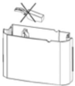
Fig./Img./Abb./Afb./Rys./Obr. 6
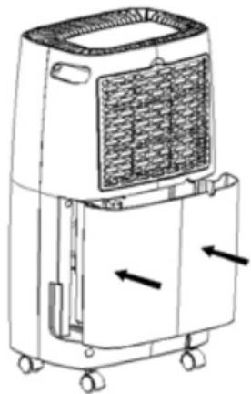
Fig./Img./Abb./Afb./Rys./Obr. 7
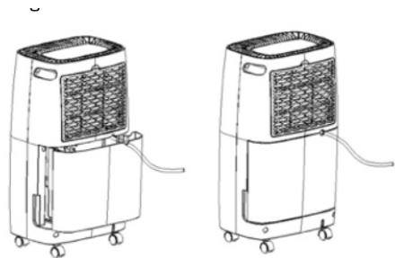
Fig./Img./Abb./Afb./ Rys./Obr. 8
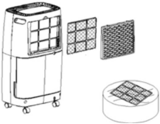
Fig./Img./Abb./Afb./Rys./Obr. 9

Fig./Img./Abb./Afb./Rys./Obr. 10
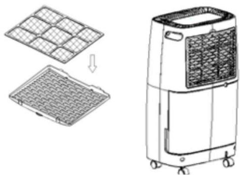
Fig./Img./Abb./Afb./Rys./Obr. 11
www.cecotec.es




- SOMMAIRE
- INSTRUCTIONS DE SÉCURITÉ
- CONTROL PANEL. FIG. 2
- NOTE
- BEFORE USE
- OPERATION
- DRAINING COLLECTED WATER
- EMPTYING THE WATER TANK
- CONTINUOUS WATER DRAINAGE. FIG. 8
- CLEANING AND MAINTENANCE
- CLEANING THE FILTER
- STORAGE
- TROUBLESHOOTING
- SERVICE INFORMATION
- 1.1 AREA VERIFICATION
- WORK PROCEDURE
- GENERAL WORKSPACE
- REFRIGERANT VERIFICATION
- PRESENCE OF FIRE EXTINGUISHERS
- ABSENCE OF IGNITION SOURCES
- VENTILATION
- VERIFICATION OF REFRIGERATION EQUIPMENT
- VERIFICATION OF ELECTRICAL DEVICES
- REPAIR OF SEALED COMPONENTS
- REPAIR OF INTRINSICALLY SAFE COMPONENTS
- WIRING
- DETECTION OF FLAMMABLE REFRIGERANTS
- LEAK-DETECTION METHODS
- REMOVAL AND EVACUATION
- LOADING PROCEDURE
- COMMISSIONING
- LABELLING
- RECOVERY
- TECHNICAL SPECIFICATIONS
- DISPOSAL OF OLD ELECTRICAL AND ELECTRONIC APPLIANCES
- TECHNICAL SUPPORT AND WARRANTY
- COPYRIGHT
- PIÈCES ET COMPOSANTS
- PROBLEEMOPLOSSING
Brand : CECOTEC
Model : Bigdry 4000 Expert M
Category : Washing machine