
ESPRIMO P5925 - Desktop computer FUJITSU SIEMENS - Free user manual and instructions
Find the device manual for free ESPRIMO P5925 FUJITSU SIEMENS in PDF.


| Product Type | Desktop Computer |
| Brand | FUJITSU SIEMENS |
| Model | ESPRIMO P5925 |
| Supported Processor | Intel Core 2 Duo, Pentium Dual Core, Celeron (LGA 775, FSB 800/1066/1333 MHz, max 65 W) |
| RAM Memory | DDR2 667/800, up to 8 GB, 2 channels, 240 pins, 1.8 V |
| Graphics Card | Intel GMA 3100, 256 MB video memory, ADD2 support for dual DVI |
| Display Resolutions | 1024x768 (200 Hz), 1280x1024 (120 Hz), 1600x1200 (120 Hz), 1440x900, 1680x1050, 1920x1200 |
| External Ports | 2x PS/2 (keyboard, mouse), LAN RJ-45, 4x USB 2.0, audio (line-in, line-out, microphone), VGA, serial port |
| Storage | SATA (2 ports) – not detailed |
| Power Supply | Not specified (standard AC power supply) |
| Dimensions | Not specified (standard tower format) |
| Weight | Not specified (approximately 8-12 kg) |
| Main Features | Dual-channel memory mode, ADD2 support, BIOS update, IRQ management |
| Maintenance and Cleaning | Discharge static electricity before handling; do not touch the pins |
| Safety | Unplug before intervention; follow electrostatic precautions |
| Spare Parts and Repairability | Processor, memory, PCI/PCIe cards, cooler, BIOS |
| General Information | PDF notice available; BIOS updates at www.fujitsu-siemens.com/mainboards |
Frequently Asked Questions - ESPRIMO P5925 FUJITSU SIEMENS
User questions about ESPRIMO P5925 FUJITSU SIEMENS
0 question about this device. Answer the ones you know or ask your own.
Ask a new question about this device
Download the instructions for your Desktop computer in PDF format for free! Find your manual ESPRIMO P5925 - FUJITSU SIEMENS and take your electronic device back in hand. On this page are published all the documents necessary for the use of your device. ESPRIMO P5925 by FUJITSU SIEMENS.
USER MANUAL ESPRIMO P5925 FUJITSU SIEMENS
Mainboard D2581/D2584

Sie haben...
...any technical problems or other questions you need clarified?
Please contact:
- your sales partner or your sales outlet
- our hotline via the contact form at "www.fujitsu-siemens.com/support/contact/contact.html", or for customers who have purchased an individual mainboard: +49(0) 180 3777 005
The latest information and updates (e.g. BIOS update) on our mainboards can be found on the Internet at: "www.fujitsu-siemens.com/mainboards"
Copyright © Fujitsu Siemens Computers GmbH 2007
Intel, Pentium and Celeron are registered trademarks of Intel Corporation, USA.
Microsoft, MS, MS-Dos and Windows are registered trademarks of Microsoft Corporation.
PS/2 and OS/2 Warp are registered trademarks of International Business machines, Inc.
All other trademarks referenced are trademarks of their respective owners, whose protected rights are acknowledged.
All rights, including rights of translation, reproduction by printing, copying or similar methods, even of parts are reserved.
Offenders will be liable for damages.
All rights, including rights created by patent grant or registration of a utility model or design, are reserved. Delivery subject to availability.
Right of technical modification reserved.
| List of onboard Features | D2581 | D2584 |
| Chipset | Intel® iQ33 | Intel® iQ35 |
| Board size | μBTX | μBTX |
| VGA | ✓ | ✓ |
| Audio / 8-channel / S/PDIF | ✓ / - / - | ✓ / - / - |
| Buzzer / int. Speaker Support | - / ✓ | - / ✓ |
| LAN 1 Gbit / 100 Mbit/ 10 Mbit | ✓ / ✓ / ✓ | ✓ / ✓ / ✓ |
| LAN ASF /Aol / WoL / Boot /iAMT | ✓ / - / ✓ / ✓ / - | ✓ / - / ✓ / ✓ / ✓ |
| Serial ATA / ATA / RAID | ✓ / - / - | ✓ / - / ✓ |
| FireWireTM / USB 2.0 | - / ✓ | - / ✓ |
| FAN monitored PSU* / CPU FAN(1) / AUX1 (FAN2) / AUX2 (FAN3) | - / - / - / - | ✓ / ✓ / ✓ / - |
| FAN controlled PSU* / CPU FAN(1) / AUX1 (FAN2) / AUX2 (FAN3) | ✓ / ✓ / ✓ / - | ✓ / ✓ / ✓ / - |
| TEMP monitored CPU / ONB1 / ONB2 / HDD | ✓ / ✓ / ✓ / - | ✓ / ✓ / ✓ / - |
| SmartCard SystemLock (USB / serial) | ✓ / - | ✓ / - |
| Fujitsu Siemens Computers Keyboard Power Button Support | ✓ | |
| Special onboard features | D2581 | D2584 |
| Silent Fan / Silent Fan LT / System Guard / Silent Drives | - / ✓ / ✓ / ✓ | ✓ / - / ✓ / ✓ |
| Recovery BIOS / Desk Update / Multi Boot / Safe Standby | ✓ / ✓ / ✓ / ✓ | ✓ / ✓ / ✓ / ✓ |
| HDD Password / Logo Boot / Intel On Screen Branding | ✓ / ✓ / ✓ | ✓ / ✓ / ✓ |
- not supported by standard Power Supplies
| Special Features | |
| Green Edition | Halogen-free and lead-reduced product |
| Silent Fan | Independent temperature related processor fan and system fan supervision and control |
| System Guard | View and adjust Silent Fan |
| Silent Drives | Noise reduction for optical and hard disk drives |
| Safe Standby | Prevents data loss in S3 (Save-to-RAM) |
| Recovery BIOS | Restores a corrupted BIOS |
| Desk Update | Simple driver update with DU CD |
| Multi Boot | Comfortable boot from any boot device |
| HDD Password | Access protection for ATA5/ATA15 disk drives |
| Silent Fan LT | Independent temperature related processor fan and system fan control |
Information about boards

Be sure to observe the following for boards with ESD:
- You must always discharge static build up (e.g. by touching a grounded object) before working with the board.
The equipment and tools you use must be free of static charge. - Remove the power plug from the mains supply before inserting or removing boards.
Always hold boards by their edges. - Never touch connector pins or conductors on the board.
An overview of the features is provided in the data sheet.
Special features
Your mainboard is available in different configuration levels. Depending on the configuration, your mainboard will be equipped with or provide support for certain features.
This manual describes the most important properties of this mainboard.
Additional information on mainboards is provided in the manual "Basic information on mainboard" on the "User Documentation" or "OEM Mainboard" CD, or on the Internet.
Interfaces and connectors
The location of the interfaces and connectors of your mainboard is specified at the beginning of the manual.
The components and connectors marked are not necessarily present on the mainboard.
External ports
The location of the external connections of your mainboard is specified at the beginning of the manual.
| PS/2 keyboard port, violet (optional) | PS/2 mouse port, green (optional) |
| LAN port (RJ-45) | Microphone jack (mono), pink |
| Audio input (Line in), light blue | USB - Universal Serial Bus, black |
| Audio output (Line out), light green | VGA, blue |
| Serial interface, turquoise |

The external USB ports on the back of the computer support a combined maximum load of 2 A.
Graphics controller
Intel GMA 3100
256 MByte Video Memory
Support of ADD2 cards (single and dual DVI adapter cards)
| Resolution (colour depth up to 32 bits/pixel) | Frequency |
| 1024 x 768 (recommended / max*) | 120 / 200 Hz |
| 1280 x 1024 (recommended / max*) | 100 / 120 Hz |
| 1600 x 1200 (recommended / max*) | 85 / 120 Hz |
| 1440 x 900 Widescreen TFT (VGA/DVI) | x/x |
| 1680 x 1050 Widescreen TFT (VGA/DVI) | x/x |
| 1920 x 1200 Widescreen TFT (VGA/DVI) | x/x |
| * Maximum video refresh rate for the graphics setting. The video quality may be deteriorated if the maximum setting is used. |
Installing/removing the processor

Disconnect the system from the mains voltage before performing any of the tasks described below. Details are contained in the operating manual of your system.
Technical data
- Socket LGA 775, max. 65W; Intel® Core 2 DUO Processors 1333/1066/800 MHz FSB; Intel® Pentium Dual Core E2xxx Processors 800 MHz FSB, Intel® Celeron® Processors 4xx 800 MHz FSB
- A current list of the processors supported by this mainboard is available on the Internet at: "www.fujitsu-siemens.com/mainboards".

Never touch the underside of the processor. Even minor soiling such as grease from the skin can impair the processor's operation or destroy the processor. Place the processor in the socket with extreme care, as the spring contacts of the socket are very delicate and must not be bent.
If one or more spring contacts are bent, on no account insert the processor as it may be damaged by doing so. Please contact the responsible vendor.
Procedure

The processor socket is covered with a protective cap to protect the spring contacts. In the event of a warranty claim, the mainboard can only be taken back by Fujitsu Siemens Computers with the protective cap secured!
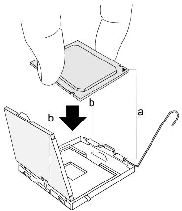
Remove the heat sink.
Press down the lever and unhook it.
Fold up the frame.
Hold the processor between your thumb and index finger and insert it into the socket (b) so that the marking of the processor is aligned with the marking on the socket (a).
Press the lever downward until it is hooked in again.
Remove the protective cap and keep it.

Please note that, depending on the heat sink used, different heat sink mounts are required on the mainboard.
Depending on the configuration variant, you must pull a protective foil off the heat sink or coat the heat sink with heat conducting paste before fitting it.
- Secure the heat sink - depending on the model - with four screws or push it into the mounts.
Installing/removing main memory
Technical data
| Technology | DDR2 667 / 800 unbuffered DIMM modules 240-Pin; 1.8V; 64 Bit, no ECC |
| Total size | 128 MByte to 8 GByte |
| Module size | 128, 256, 512, 1024 or 2048 MByte for one socket |
A current list of the memory modules recommended for this mainboard is available on the Internet at: "www.fujitsu-siemens.com/mainboards".
At least one memory module must be installed. Memory modules with different memory capacities can be combined.

You may use only unbuffered 1.8V memory modules without ECC.
DDR2-memory modules must meet the PC2-5300U or PC2-6400U specification.

If you use more than one memory module, make sure to distribute the memory modules over both memory channels. By doing this you use the performance advantages of the dual-channel mode.
System performance is maximised when the same memory size is used in Channel A and Channel B.
To simplify equipping, the slots are colour coded.
With a memory configuration of 8 Gbytes the visible and usable main memory can be reduced down to 7 Gbytes (depending on the system configuration).

| Number of memory modules inserted | ||||
| Slot to be used | 1 | 2 | 3 | 4 |
| Channel A, Slot 1 | X | X | X | X |
| Channel B, Slot 2 | X | X | X | |
| Channel A, Slot 3 | X | X | ||
| Channel B, Slot 4 | X | |||
The installation/removal is described in the "Basic information on mainboard" manual.
PCI bus interrupts - Selecting correct PCI slot
Extensive information on this section is contained in the manual "Basic information on mainboard".

To achieve optimum stability, performance and compatibility, avoid the multiple use of ISA IRQs or PCI IRQ Lines (IRQ sharing). Should IRQ sharing be unavoidable, then all involved devices and their drivers must support IRQ sharing.
Which ISA IRQs are assigned to the PCI IRQ Lines is normally automatically specified by the BIOS (see "BIOS Setup" description).
Monofunctional expansion cards
PCI/PCI Express expansion cards require a maximum of one interrupt, which is called the PCI interrupt INT A. Expansion cards that do not require an interrupt can be installed in any desired slot.
Multifunctional expansion cards or expansion cards with integrated PCI-PCI bridge
These expansion cards require up to four PCI interrupts: INT A, INT B, INT C, INT D. How many and which of these interrupts are used is specified in the documentation provided with the card.
The assignment of the PCI interrupts to the IRQ Lines is shown in the following table:
On board controller
| PCI INT LINE | 1 (A) | 2 (B) | 3 (C) | 4 (D) | 5 (E) | 6 (F) | 7 (G) | 8 (H) |
| UHCI USB 1.1 | ||||||||
| Dev 1A Fn 0 1th | - | - | - | - | X | - | - | - |
| Dev 1A Fn 1 2nd | - | X | - | - | - | - | - | - |
| Dev 1D Fn 0 3rd | - | - | - | - | - | - | - | X |
| Dev 1D Fn 1 4th | - | - | - | - | - | - | X | - |
| Dev 1A Fn 2 5th | - | - | - | - | - | X | - | - |
| EHCI USB 2.0 | ||||||||
| Dev 1A Fn 7 | - | X | - | - | - | - | - | - |
| Dev 1D Fn 7 | - | - | - | - | - | - | - | X |
| SATA #1 | - | - | - | X | - | - | - | - |
| SATA #2 | - | X | - | - | - | - | - | - |
| SMBus | - | - | - | X | - | - | - | - |
| Intel LAN | - | - | X | - | - | - | - | - |
| HD Audio | - | - | - | - | X | - | - | - |
| Broadcom LAN | D | A | B | C | - | - | - | - |
| Onboard Graphik | X | - | - | - | - | - | - | - |
Mechanical slot
| PCI INT LINE | 1 (A) | 2 (B) | 3 (C) | 4 (D) | 5 (E) | 6 (F) | 7 (G) | 8 (H) |
| PCI | ||||||||
| Slot 1 | - | - | D | C | - | B | A | - |
| Slot 2 | - | - | C | D | - | A | B | - |
| PCIe x16 | A | B | C | D | - | - | - | - |
| PCIe X1 | - | - | - | - | - | - | x | - |
Use first PCI/PCI Express slots that have a single PCI IRQ Line (no IRQ sharing). If you must use another PCI/PCI Express slot with IRQ sharing, check whether the expansion card properly supports IRQ sharing with the other devices on this PCI IRQ Line. The drivers of all cards and components on this PCI IRQ Line must also support IRQ sharing.
BIOS Update
When should a BIOS update be carried out?
Fujitsu Siemens Computers makes new BIOS versions available to ensure compatibility with new operating systems, new software or new hardware. In addition, new BIOS functions can also be integrated.
A BIOS update should also always be carried out when a problem exists that cannot be solved with new drivers or new software.
Where can I obtain BIOS updates?
The BIOS updates are available on the Internet at "www.fujitsu-siemens.com/mainboards".
BIOS update under DOS with bootable BIOSupdate floppy disk - brief description
Download the update file from our website to your PC.
Insert an empty floppy disk (1.44 Mbyte).
Run the update file (e.g. 2461103.EXE).
A bootable update floppy disk is created. Leave this floppy disk in the drive.
Restart the PC.
Follow the instructions on screen.

Detailed information on the BIOS update under DOS is provided in the "BIOS Setup" manual ("Drivers & Utilities" CD).
BIOS update under Windows with DeskFlash utility
A BIOS update can also be carried out directly under Windows with the DeskFlash utility. DeskFlash can be found on the "Drivers & Utilities" CD (under DeskUpdate).
KpaTKoe OINcaHne MaTePNHcKOIJIaTbI
Yka3aHnI NO MOyJAM

Дя моун e EGB o6aTeNbH O yuTbIaIe TcneDyUouee:
Ipeed pa6otoi C moylaMn tpe6yetc ctaTneckn pa3pndntb cboe TeNo (Hanpimep, nocpeDCTBOM KacaHna KaKoro-Jin6o 3aemnenHoro npedMeTa).
- IckIIOHHTb BO3MOXHOCTb CtaTnueCKOro 3apraJa IcIIOJIb3yEmbIX yCTpoiCTB INHCTpyMeHToB.
- Ipeed yctaHOBkoI INI CHrTHeM MOyJeN BbIHbTe BnIKy CeTeBOrO Ka6eJIa n3 po3eTKN.
KacaTecb TOnbKO KpOMOK MOnyne.
He npikacaiTecb K UItbIpbKOBbIM BblBODaM IIN neaTHbIM IpOBOHnKaM MOdyIa.
O630p npo13BODCTBeHHbIX noka3aTeJe Bbl HaIeTe B texHueckom nacnOpTe.
OTnHHTeJIbHbIe OcO6eHHoCTn
Bb moxete npno6pectn Bauy MaTePNHckyI NaTy B pa3NnHybIX KOHpyrpaQIOHHbIX NCnonHeHnx. Ba7a MaTePNHcKa INaTa B 3aBNCMOCTn OT CBOe KOHpyrpaQIM O6naJaet ONpeJeHbIM NOKa3aTeYMa INI NODepKINBaET IX.
B 3TOM PykoBoDCTBe NO 3KcNJIyatauIN BbI HauDeTe OINcaHne BaXHeiux CBOIcTB 3ToI MaTePHNCHKO IIaTbI.
PnKoHpyaunn narnTn pa3mepom B 8 7aBnMoe nncnoB3yemoe O3y MoKeT 6bTcokpaueHO do 7 6aHT (B 3abNCMOCTn OT KOHpyaunn cnTeMbI).

- Mainboard D2581/D2584
- Sie haben...
- Special features
- Interfaces and connectors
- External ports
- Graphics controller
- Installing/removing the processor
- Technical data
- Procedure
- Installing/removing main memory
- PCI bus interrupts - Selecting correct PCI slot
- Monofunctional expansion cards
- Multifunctional expansion cards or expansion cards with integrated PCI-PCI bridge
- BIOS Update
- BIOS update under DOS with bootable BIOSupdate floppy disk - brief description
- BIOS update under Windows with DeskFlash utility
- KpaTKoe OINcaHne MaTePNHcKOIJIaTbI
- OTnHHTeJIbHbIe OcO6eHHoCTn
Brand : FUJITSU SIEMENS
Model : ESPRIMO P5925
Category : Desktop computer