
553 - Sewing machine PFAFF - Free user manual and instructions
Find the device manual for free 553 PFAFF in PDF.
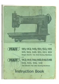


| Product Type | Sewing Machine (Mechanical) |
| Brand | Pfaff |
| Model | 553 |
| Country of Manufacture | West Germany |
| Control Type | Manual (Mechanical) |
| Power Supply | 220-240V AC, 50Hz |
| Power Consumption | 85 W |
| Max Sewing Speed | ~800 stitches/min |
| Built-in Stitches | 23 patterns |
| Stitch Length Range | 0-4 mm |
| Stitch Width Range | 0-5 mm |
| Buttonhole Type | 4-step automatic |
| Reverse Stitch | Yes, lever operated |
| Needle Threader | Built-in |
| Bobbin Winder | Integrated, clutch-controlled |
| Free Arm | Convertible free arm for sleeves and cuffs |
| Work Lighting | Built-in lamp |
| Included Accessories | Standard presser feet, bobbins, needles, screwdriver, seam ripper |
| Carrying Case | Hard case included |
| Dimensions (L x W x H) | 42 x 20 x 30 cm (16.5 x 7.9 x 11.8 in) |
| Weight | 8.5 kg (18.7 lb) |
| Maintenance | Clean and oil hook area and feed dogs after 8-10 hours of sewing |
| Safety Features | Finger guard, integrated thread cutter, hot-plug protection |
| Spare Parts | Bobbins, needles, presser feet and drive belts readily available |
| Repairability | Modular internals, easily serviced with standard tools |
Frequently Asked Questions - 553 PFAFF
User questions about 553 PFAFF
0 question about this device. Answer the ones you know or ask your own.
Ask a new question about this device
Download the instructions for your Sewing machine in PDF format for free! Find your manual 553 - PFAFF and take your electronic device back in hand. On this page are published all the documents necessary for the use of your device. 553 by PFAFF.
USER MANUAL 553 PFAFF
R 6499
PFAFF
Single-Needle Flat-Bed Sewing Machines and
PEAFF
Two-Needle Flat-Bed Sewing Machines
Instruction Book
Instructions
for
Pfaff 141 and 143 Machines
Additional Instructions
for Pfaff Machines
141-5; 141-5-900/05; 141-5-225; 143-5; 143-5-225; 145; 151;
153; 155; 142; 142-900/06; 144; 144-900/06; 146; 148;
543 U-12; 546/548; 4141 and 4143
These instructions also apply to Pfaff machines
541; 543; 545; 551; 553; 555; 542; 544; 544 U-12; 546; 548 and 4145
1. General
All the machines covered by this Instruction Book, with the exception of Pfaff machines 4141 and 4143, are organized with vertical rotary hook and sleeve take-up. Since their operation is more or less the same, the general instructions contained in the first part of this book pertain to all of them.
Special instructions which are necessitated by special features of construction are contained in the second part of this book.
It is recommended to run these machines at the following top speeds:
| Pfaff 141, 142, 143, 144, 151 and 153 | 3,000 s.p.m. |
| Pfaff 145 and 155 | 2,800 s.p.m. |
| Pfaff 146 | 2,600 s.p.m. |
| Pfaff 148 with puller feed | 2,200 s.p.m. |
| Pfaff 543 U-12 | 1,400 s.p.m. |
| Pfaff 546/548 with puller feed | 1,800 s.p.m. |
| Pfaff 4141 and 4143 | 1,500 s.p.m. |
When sewing tightly woven and heavily dressed materials, the sewing speed should be reduced in order to prevent overheating of the needle.
The maximum speed of two-needle machines decreases as the needle gauge increases. The maximum speeds which can be attained with machines fitted with special attachments or trimming mechanisms often are far below the recommended top speeds because the nature of the work and the thickness of the material tend to limit the machine's capacity. If the maximum speed is exceeded, trouble may develop chiefly in the trimming mechanism.
To avoid trouble in the mechanism, run the machine at about 70 per cent of their top speed until the parts which are in movable contact have become thoroughly glazed by their action upon each other. This should normally be the case after about two weeks' constant use.
All machines are regularly equipped with a fixed pulley which is cast in one with the balance wheel. If desired, however, these machines can be supplied with a disengageable pulley.
If fitted with the latter type pulley, the machine is dispatched with the sewing mechanism disengaged. To engage this mechanism for sewing, hold the balance wheel steady with your left hand and turn the large lock nut clockwise.
2. Fundamentals of Machine Operation
Before you put the machine in operation for the first time, carefully remove all dust which has accumulated in transit and oil the machine thoroughly (see Chapter 3).
Oil the machine only with Pfaff sewing machine oil which is non-resinous and acid-free. Never run a threaded machine unless you have fabric under the presser foot or the vibrating presser.
Before you start sewing, lay both threads back under the presser foot.
To prevent thread jamming, hold both thread ends until the machine has made a few stitches.
Do not pull the material while stitching; the machine will feed the fabric automatically.
Use needles of the correct system only (see Chapter 6).
Never use rusty needles.
Use high-quality threads only.
Always bring the take-up lever to its highest point before you remove the material.
3. Cleaning and Oiling
Careful cleaning and regular oiling will increase the service life of your machine.
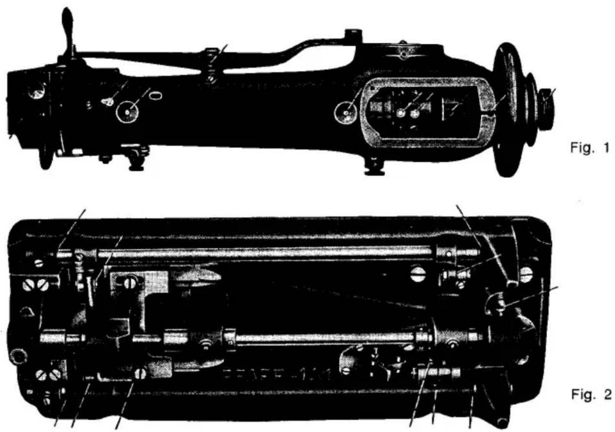
After you have removed the dust which has accumulated on the machine in transit, take a clean rag and remove the grease from all nickel-plated and polished parts. Apply a few drops of kerosene to all oiling points marked with dash lines in Figs. 1, 2 and 3, raise the presser foot, unthread the needle and remove the bobbin case. Apply a few drops of Pfaff sewing machine oil No. 280-1-120 122 to all points of friction.
While these points of friction should be oiled twice a week, the sewing hook must be oiled each day the machine is in operation. Make particularly sure that oil is applied to oilhole R (Fig. 4).
Although the bevel gears are enclosed in cases and require no special maintenance, it is recommended to replace the old grease by Pfaff grease No. 280-1-120 243 once a year. Owing to the special lubricating properties of this grease, the flanks of the bevel gear teeth should be greased only lightly.
From time to time remove the needle plate after taking out set screws 14 and 15 (Fig. 4) and remove the lint which has accumulated underneath. It is recommended at the same time to dismantle the sewing hook and clean it thoroughly (see Chapter 13). In replacing the needle plate make sure that position finger F (Fig. 13) on the bobbin case base enters slot P on the underside of the needle plate.
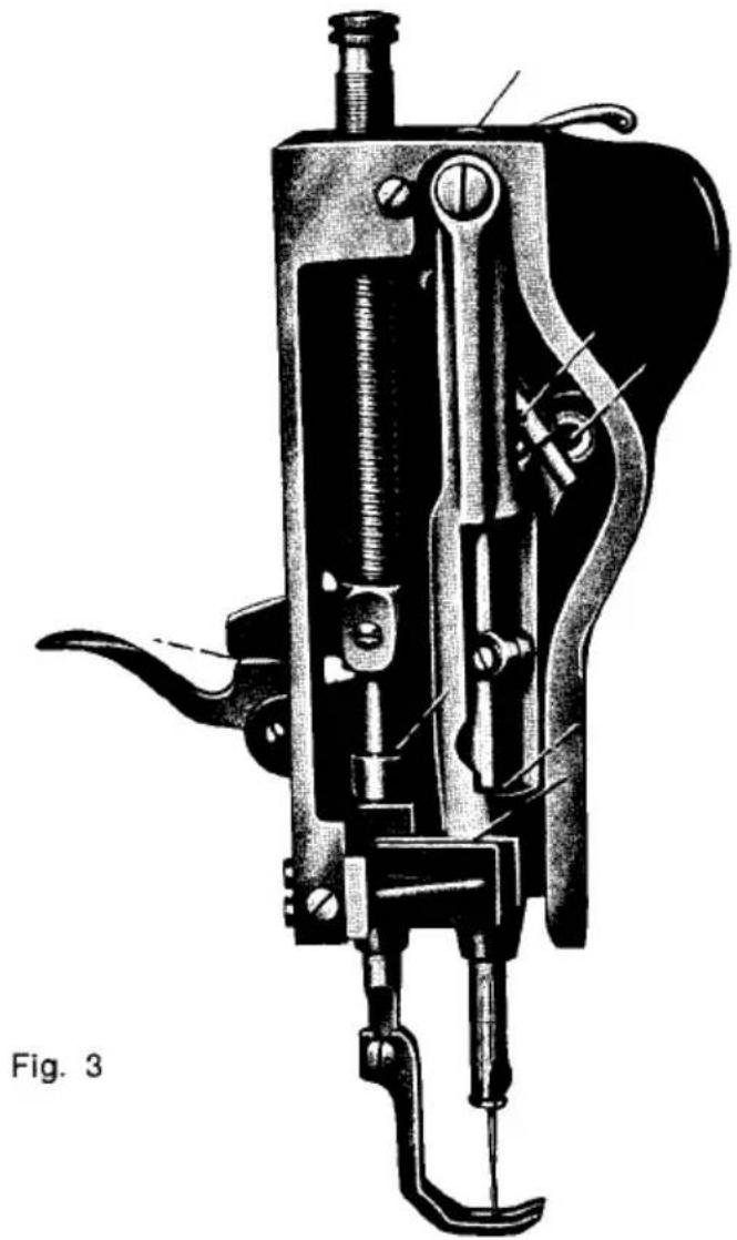
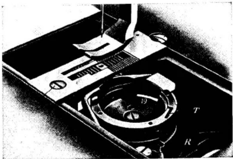
Fig. 4
4. Winding the Bobbin
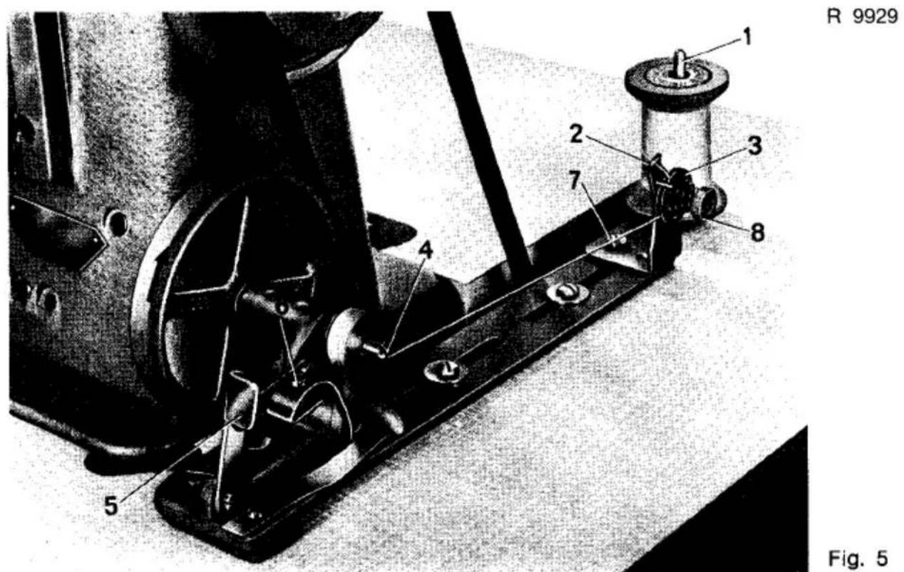
Place a spool of thread on pin 1 (Fig. 5) and pass the thread from left to right through eyelet 2, clockwise around and between tension discs 3 and from the inside through the slot in the bobbin. Wind a few turns of thread on the bobbin and place the latter on spindle 4. Start the bobbin winder by pressing down lever 5. The bobbin is wound automatically while the machine is sewing. When a sufficient amount of thread has been wound on the bobbin, a latch stops the bobbin winder.
The amount of thread to be wound on the bobbin is regulated by screw 6.
Turn this screw clockwise for more thread, or counter-clockwise for less thread.
If the thread should pile up at one end of the bobbin, adjust the position of the bobbin winder tension sideways, as may be required. To do this, loosen screw 7, adjust tension and tighten the set screw again.
The tension on the thread is regulated by turning nut 8.
Make sure the bobbin winder pulley rotates in the direction indicated by an arrow in Fig. 5.
5. Changing the Bobbin and Threading the Bobbin Case
Raise the needle to its highest position and open the bed slide. With the thumb of your right hand open latch B (Fig. 6), then push the thumb nail under the projecting flange C of the bobbin case cap and lift the latter out of the machine with thumb and forefinger. The bobbin is now exposed in the bobbin case base and can be taken out easily.
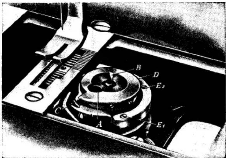
Fig. 6
Place a full bobbin in the bobbin case cap so that the thread draws on top from left toward the right, as shown in Fig. 7.
Hold the bobbin steady in the bobbin case, pull the thread into slot X and draw it under the tension spring Y. Leave a loose end of thread about 3" long outside the bobbin case.
Place the bobbin case with the bobbin on the center stud in the bobbin case base and close latch B (Fig. 6) as well as the bed slide.
Note that the rotary hook of Pfaff machines 153 and 155 is located on the left of the needle plate.
R 9931
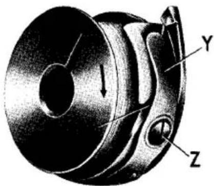
Fig. 7
6. Selecting the Correct Needle
To ensure reliable stitch formation, check to see that the correct needle is inserted in the machine.
Needle Systems
All Pfaff machines 141, 142, 143, 144, 148, 151, 153 and 546/548 use ordinary System 134 needles, while Pfaff machines 141-35, 4141 and 4143 use System 134-35 needles and Pfaff machines 543 U-12 use System 190 needles.
Pfaff unison-feed machines 145, 146 and 155 in Models H1 and H2 use System 134 needles, while Model H3 uses System 134-35 needles and Model H4 uses System 190 needles.
Needle Point Styles
These needles are available with different type points to suit different requirements. The various needle point styles are identified by a letter following the needle system, e.g. 134 R.
Fabrics are stitched with a round-point needle, identified by R, while for leather work needles are available with the following styles of points:
Lr Narrow reverse twist point
LI Narrow twist point
Lack ■ Patent leather point
P ■ Extra-narrow wedge point
PCr ▼ Extra-narrow wedge point with right-twist groove
PCI ■ Extra-narrow wedge point with left-twist groove
S . Narrow cross point; for long, straight stitches
D ▲ Triangular point; for short, straight stitches
Vr . Reverse twist spear point
VI Twist spear point
Rubberized fabrics and plastic materials are sewn with round-point needles.
Needle and Thread Sizes
The correct needle size is dependent on the fabric and thread weights. For best results, select the needle as thin as possible, but make sure the thread can be pulled through the needle eye easily.
| Needle Size | Cotton | Silk | Synthetic | Linen |
| 60 | 130/3130/4 | 140/3 | 200/3-150/3 | |
| 70 | 100/3100/4 | 120/3 | 140/3-120/3 | |
| 80 | 80/380/4 | 100/3 | 120/3-100/3 | |
| 90 | 70/3-60/370/4-60/4 | 80/3 | 100/3- 80/3 | 70/3 |
| 100 | 50/3-40/350/4-40/4 | 70/3 | 70/3 | 60/3 |
| 110 | 30/330/430/6 | 60/3 | 60/3 | 50/3 |
| 120 | 24/324/6 | 50/3 | 50/3 | 40/3 |
| 130 | 20/3 | 40/3 | 40/3 | 35/3 |
| 140 | 12/312/6 | 30/3 | 30/3 | .30/3 |
| 150 | 10/98/6 | 25/3 | 20/3 | 25/3 |
| 160 | 6/6 | 20/3 | 18/3 | 20/3 |
| 170 | 6-ply fancy-effect thread | 10/3 | 15/3 | 18/3 |
| 180 | 9-ply fancy-effect thread | 10/3 | 10/3 | 18/3 |
| 190 | 9-ply fancy-effect thread | 0.6 mm dia. | 18/4 | |
| 200 | 12-ply fancy-effect thread | 1.0 mm dia. | 18/4 |
The needle size should be selected to match not only the thread weight, but also the machine model, as follows:
Model A: Needle sizes 60-80
Model B: Needle sizes 90–110
Model C: Needle sizes 120–160
Model D: Needle sizes 170–200
The needle size is indicated on the shank in hundredths of millimeters. Thus, a No. 100 needle has a shaft diameter of 100/100 = 1 mm.
7. Changing the Needle
Raise the needle bar to its highest point, loosen the needle set screw half a turn, and pull the damaged needle out of the needle clamp.
Insert a new needle into the clamp, making sure that its short groove faces toward the sewing hook. Push the needle up as far as it will go and tighten the needle set screw securely.
Never use rusty needles.
8. Threading the Needle
Pass the thread from spool 1 (Fig. 8) through the holes in stud 2 and thread guide 3, around thread retainer 4, clockwise around and between tension discs 5, under thread controller disc 6, through thread check spring 7, up and through thread guide 8, from right to left through the hole in take-up lever 9, then down and through thread guides 10, 11 and 12, and from left to right through the eye of the needle.
The spool holder on top of the machine arm in future will be supplied on special request only because the thread stand which is supplied with the machine regularly ensures a smoother passage of the thread to the needle.

Fig. 8
9. Drawing Up the Bobbin Thread
Hold the end of the needle thread and turn the balance wheel toward you, as indicated by an arrow in Fig. 8, until the needle moves down and up again. As the needle moves up, it catches the bobbin thread which comes up with it through the needle hole. Lay both threads back under the presser foot, place the material in the machine and lower the presser foot. Hold the ends of both threads until the machine has made a few stitches.
10. Regulating the Thread Tensions
Adjusting the Upper Tension
Turn tension nut M (Fig. 8) clockwise for more tension, or counter-clockwise for less tension.
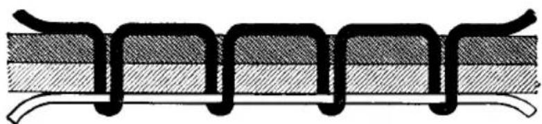
If the upper tension is too loose, the bobbin thread will draw the needle thread down so that it forms small kinks on the underside of the material, as shown in Fig. 9.
If the upper tension is too tight, the bobbin thread will be pulled up (Fig. 10) or the needle thread will break.
Both tensions are correctly balanced, if the needle and bobbin threads interlock in the center of the material, as shown in Fig. 11.
Fig. 9
Upper tension too loose or lower tension too tight
Fig. 10

Upper tension too tight or lower tension too loose
Fig. 11
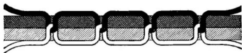
Both tensions properly balanced
When you raise the presser bar, the upper tension is released automatically so that the work can be easily removed from the machine. To do this, pull the work back (in forward feeding direction), never forward as this may cause bending of the needle, skipping of stitches or thread breaking.
Adjusting the Lower Tension
Take the bobbin case out of the machine and regulate the tension by turning screw Z (Fig. 7) with the hook screwdriver, as appropriate. Turn this screw clockwise for a tighter tension, or counter-clockwise for a looser tension.
The tension is correct if a noticeable resistance of spring Y (Fig. 7) has to be overcome when pulling the thread out of the bobbin case.
If puckering occurs on delicate materials although the tension has been set correctly, ease both tensions slightly.
11. Regulating the Stitch Length
The stitch length is regulated by turning thumb nut S (Fig. 12) on the feed regulator lever.

R 9933
Fig. 12
Turn this nut clockwise for shorter stitches, or counter-clockwise for longer stitches. The numerals on the left of the scale indicate the stitch length in millimeters. The letters V and R on the left side of the scale (Fig. 12) stand for forward and backward sewing, respectively.
All machines with the exception of the Pfaff 141-5 and 143-5 are regularly fitted with a spring-return feed regulator. This device incorporates a spring which permanently holds the feed regulator lever down in forward feeding position. When the lever is pushed up
as far as it will go, the machine will sew in reverse. And conversely, when the lever is released, forward sewing will be resumed instantly.
If desired, the machine can be fitted with a treadle which makes it possible to reverse the direction of feed by foot action.
12. Regulating the Pressure on the Material
The amount of pressure to be exerted by the presser foot must be adapted to the material to be sewn. The pressure is set correctly if the material is advanced through the machine evenly without being injured by the teeth of the feed dog.
The pressure on the material is regulated by turning screw V (Fig. 8). Turn this screw in for more pressure, or out for less pressure.
13. Cleaning the Sewing Hook
The sewing hook is the most essential part of the whole machine and, for this reason, should be cleaned thoroughly from time to time. To do this, raise the needle bar to its highest point, open the bed slide and remove the bobbin case with the bobbin. Take out the three screws E1, E2 and E3 (Fig. 6) and strip the hook gib. Turn the balance wheel until point S of the bobbin case base is about to enter groove N of the hook (Fig. 13). When in this position, the bobbin case base can be tipped out easily by seizing center stud Z with thumb and forefinger while turning the balance wheel back and forth lightly.
Clean hook and hook raceway thoroughly. If the cotton wool in slot 0 (Fig. 13) should have become matted, it should be replaced and the new cotton wool be soaked with oil.
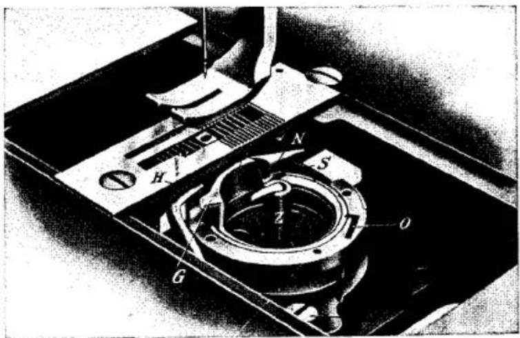
Fig. 13
To clean the vicinity of the sewing hook, take out set screw 20 (Fig. 4) and pull the hook up out of the machine. When the hook is replaced, pin 19 (Fig. 4) ensures proper positioning and eliminates the need of retiming the hook.
In replacing the bobbin case base, make sure that position finger F (Fig. 13) enters slot P on the underside of the needle plate. Replace hook gib and tighten screws E1-E3. Put a drop of oil into the hook raceway, replace the bobbin case with the bobbin and close latch B (Fig. 6).
Never run the machine with the needle plate removed as this may result in damage to the bobbin case or the bobbin case opener.
The above instructions also apply to all two-needle sewing machines covered by this Instruction Book.
14. The Safety Clutch
Model C and D machines are equipped with a safety clutch which prevents disturbance of the hook timing and damage to the bobbin case base in case of thread jamming in the hook raceway.
If an irregularly spun needle thread should jam in the hook raceway and block the sewing hook, the safety clutch automatically disengages the hook drive.
After the jammed thread has been removed, tilt back the sewing head and rotate the balance wheel, while holding the hook drive shaft steady, until the tip of the latch is positioned exactly above the groove in the clutch bushing. Now push back the spring-loaded pin so that the latch can snap into this groove.
To resume sewing, simply let down the sewing head again.

Additional Instructions
for Pfaff Machines 141-5 and 141-5-225
The Pfaff 141-5 and 141-5-225 have the same feed regulator. This new mechanism makes it possible to select the proper stitch length out of twelve different stitch lengths available. These twelve stitch lengths are divided into four stitch length groups (I–IV) having three predetermined stitch lengths each (Fig. 15).
The following table lists the stitch lengths in millimeters as well as the number of stitches per inch.
| Stitch Length Group | I | II | III | IV | ||||||||
| Stitches per Inch | 33 | 28 | 25 | 23 | 21 | 19 | 17 | 15 | 13 | 12 | 11 | 10 |
| Stitch Length in mm | 0.8 | 0.9 | 1.0 | 1.1 | 1.2 | 1.3 | 1.5 | 1.7 | 1.9 | 2.1 | 2.3 | 2.6 |
R 6575

Fig. 15
15. Regulating the Stitch Length
The stitch length is regulated as follows:
Begin by selecting the proper stitch length group from the table on p. 15 and interchange the feed gears as indicated in the feed gear housing (Fig. 17).
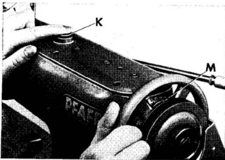
Press down button K (Fig. 16) and turn the balance wheel until the button snaps in position.
Again rotate the balance wheel backwards or forwards until notch M (Fig. 16) on the balance wheel is opposite the number of the stitch lenght group chosen (I, II, III or IV).
Release button K and turn feed regulator lever S (Fig. 15) to the desired stitch length.
R 8994
Fig. 16
16. Changing the Feed Gears
Exchanging the feed gears is greatly facilitated by the wheel puller which is supplied with the machine. To pull the feed gear off its shaft, slip the fork of the wheel puller under the projecting rim of the hub and pull (Fig. 17).
Consult the diagram on the feed gear housing (Fig. 17) to see how the feed gears have to be exchanged to obtain the stitch length group and stitch length desired. Exchange the feed gears accordingly.
For better identification, the outside of the feed gears and the corresponding symbols used in the diagram are painted yellow, green, red and blue. In slipping the feed gear onto its shaft, see that the key on the shaft enters the notch in the feed gear and that the mating gears are meshed properly.
For instructions on how to adjust the trimmer of the Pfaff 141-5-225, please refer to Chapters 18 and 19.
R 6585
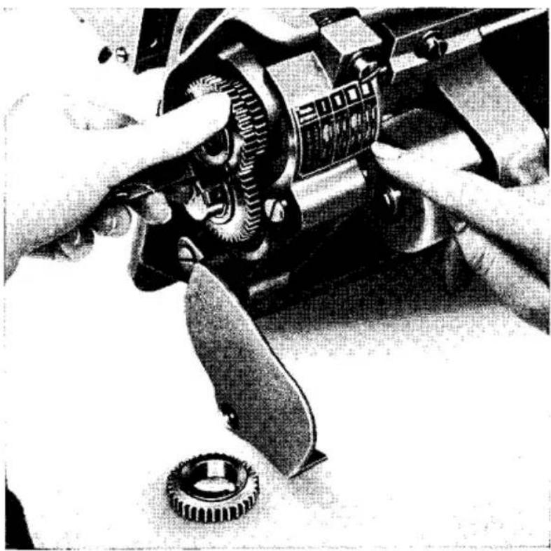
Fig. 17
Additional Instructions
for Pfaff Machines 143-5 and 143-5-225
The general instructions given for the Pfaff 143 apply also to the Pfaff 143-5 wheel-feed machine and the Pfaff 143-5-225 wheel-feed machine with horizontal trimmer. In addition, however, the following instructions should be heeded:
17. Regulating the Stitch Length
These machines are fitted with a feed gear assembly which consists of three fixed feed pinions on the feed wheel drive shaft and three loose feed gears on the feed wheel shaft. By moving the feed gears on their shaft and meshing them alternately with the corresponding feed pinions, the machine is set for any of the three predetermined stitch lengths incorporated.
To change the stitch length, pull out pin P (Fig. 18) and move lever H to position a, b or c, as desired, while turning the balance wheel. Let pin P snap into position.
To convert the machine to another stitch length group, consult the Spare Parts Catalogue which contains a list of all feed gears available for this machine.
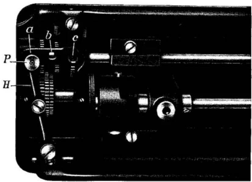
Fig. 18
18. Adjusting the Trimmer
To take out the trimming knife for sharpening, loosen set screw C (Fig. 19) swing the knife halfway between its operative and inoperative positions and pull the knife out of its guide. As you replace the knife, make sure its cutting edge bears lightly against the edge of the needle plate slot which serves as a guide. However, the knife must never be set too close to this edge as this might cause the knife to jam as it is thrown out of action. When the setting is correct, tighten set screw C securely.
The cutting stroke of the knife should be exactly halved by the needle hole. To adjust the position of the cutting edge in relation to the needle hole, loosen nut M (Fig. 19) and move the knife carrier forward or backward, as appropriate. This setting applies also to knives which have been resharpened repeatedly. After the adjustment, tighten nut M securely.
The vertical position of the knife is adjusted by screw S (Fig. 19). Turn this screw clockwise to set the knife lower, or counter-clockwise to set it higher. The knife is set correctly, if its cutting edge is positioned just above the bottom of the needle plate guide.
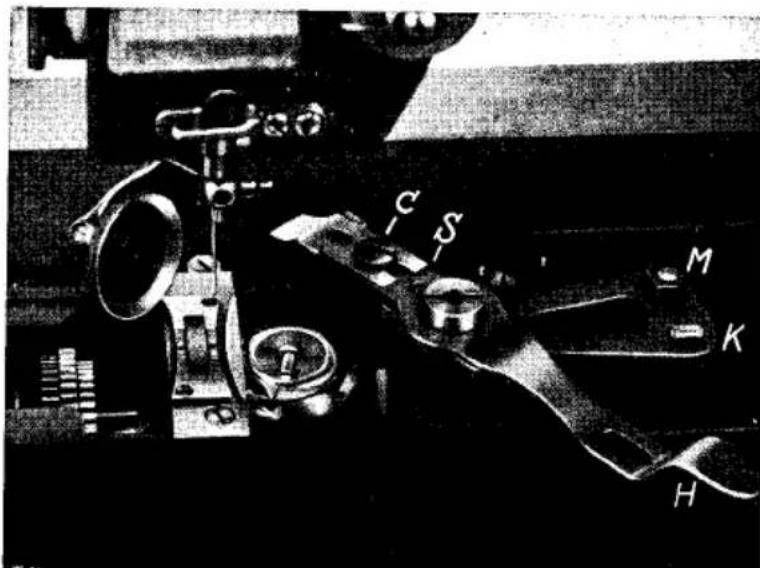
Fig. 19
It goes without saying that only a sharp and correctly set knife will produce a clean cut.
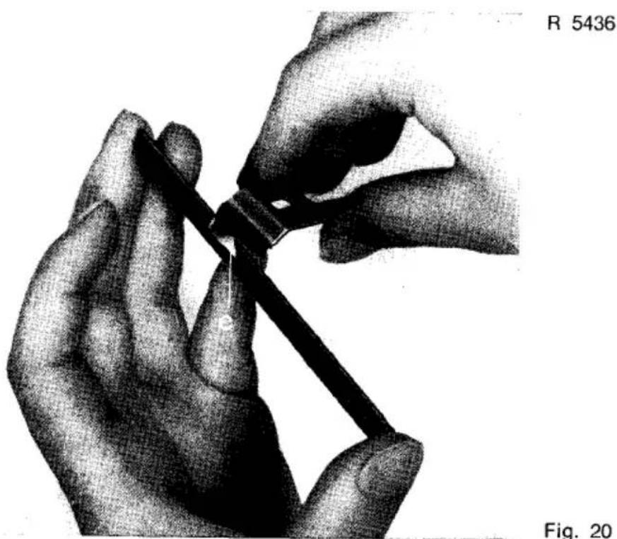
Blunt knives are sharpened with a triangular oilstone either by hand (Fig. 20) or with the aid of a knife sharpener. In sharpening the knife, take care that the cutting angle is preserved and that the cutting edge is sharpened thoroughly up to its innermost corner e which has to take most of the strain.
19. Operating the Trimmer
To engage the trimmer, turn lever H (Fig. 19) to the right until it catches on lug K on the knife carrier. To disengage it, lift lever H up slightly and swing it forward.
With the trimmer thrown out of action, the machine can be used for ordinary sewing operations.
Additional Instructions
for Pfaff Machines 145 and 155
Pfaff machines 145 and 155 are organized not only with compound feed like the Pfaff 141, but also with alternating pressers which makes them unison-feed machines capable of feeding materials that are difficult to handle.
Pfaff 145 and 155 machines differ only in the arrangement of the sewing hook. The hook of the Pfaff 145 is located on the right of the needle, while that of the Pfaff 155 is disposed on the left. Apart from the general instructions given for Pfaff machines 141 and 143 which apply to Pfaff machines 145 and 155 also, the following special instructions should be heeded:
20. Exchanging the Alternating Pressers
Raise presser bar lifter a (Fig. 21) and rotate the balance wheel to bring the needle to its highest point. Loosen screw b and pull out the vibrating presser, rotating it slightly to the right and left.
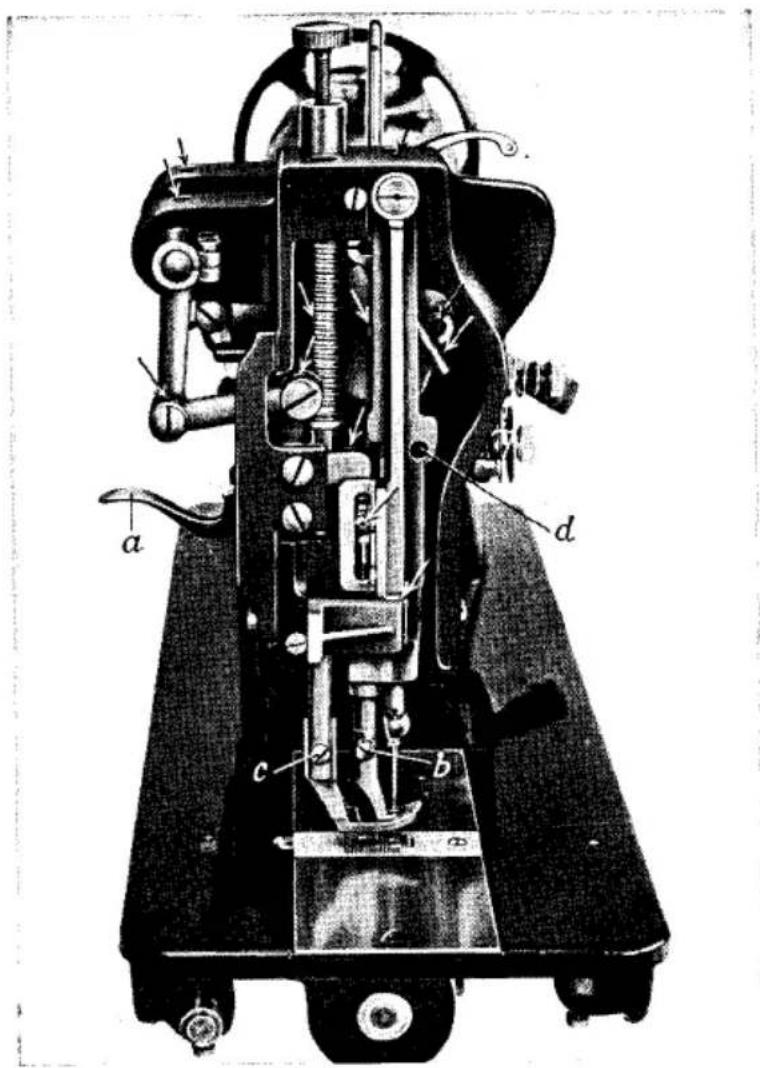
Fig. 21
In replacing the vibrating presser make sure you push it up as far as it will go and orient it so that the needle is centered in its needle hole. Then tighten screw b (Fig. 21) securely.
The lifting presser can be removed only when the presser bar is raised. To do this, take out screw c (Fig. 21) and pull out the lifting presser, tilting it back and forth slightly.
When replacing the lifting presser, push it up as far as it will go so that screw c can be pushed through the hole in its shank and tightened securely.
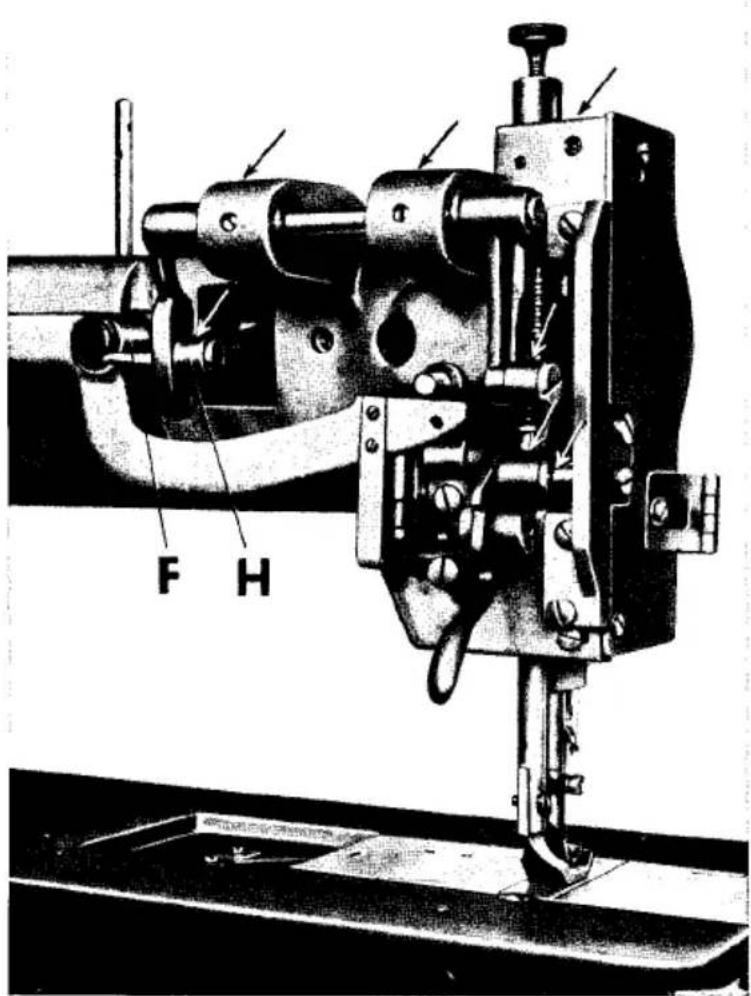
Fig. 22
21. Lubricating the Machine
Since Pfaff machines 145 and 155 are fitted with alternating pressers, they have a number of additional oiling points which are marked by arrows in Figs. 21 and 22. Of these, particularly the points of friction at the needle-bar-end of the machine, such as the needle bar (inside needle bar frame in Fig. 21) and the sleeve take-up with its round shank (behind needle bar in Fig. 21), require thorough and regular lubrication.
All moving and rotating parts should be oiled regularly. To prevent soiling of the work through dripping oil, sew a few seams on a piece of scrap material to absorb all excess oil.
Never try to remedy certain faults by applying excessive quantities of oil. Excessive oiling will merely soil the work and cause machine sluggishness. Therefore, oil the machine sparingly, but regularly.
22. Setting the Foot Lift
To adapt the foot lift to the thickness of the material to be sewn, loosen wing nut F (Fig. 22) and adjust the position of lifting eccentric connection H in the slot of the lifting crank. Move the connection upward for a higher foot lift, or downward for a lower foot lift.
Additional Instructions
for Pfaff Machines 151 and 153
Pfaff machines 151 and 153 are single-needle sewing machines organized with compound feed and ordinary drop feed, respectively. Both have the vertical rotary hook arranged on the left of the needle. Other than that, they follow the same mechanical principle built into Pfaff machines 141 and 143, respectively, so that the instructions given in Chapters 1–14 apply to them also.
Additional Instructions
for Pfaff Machines 142, 144, 146 and 148
23. Threading the Needles
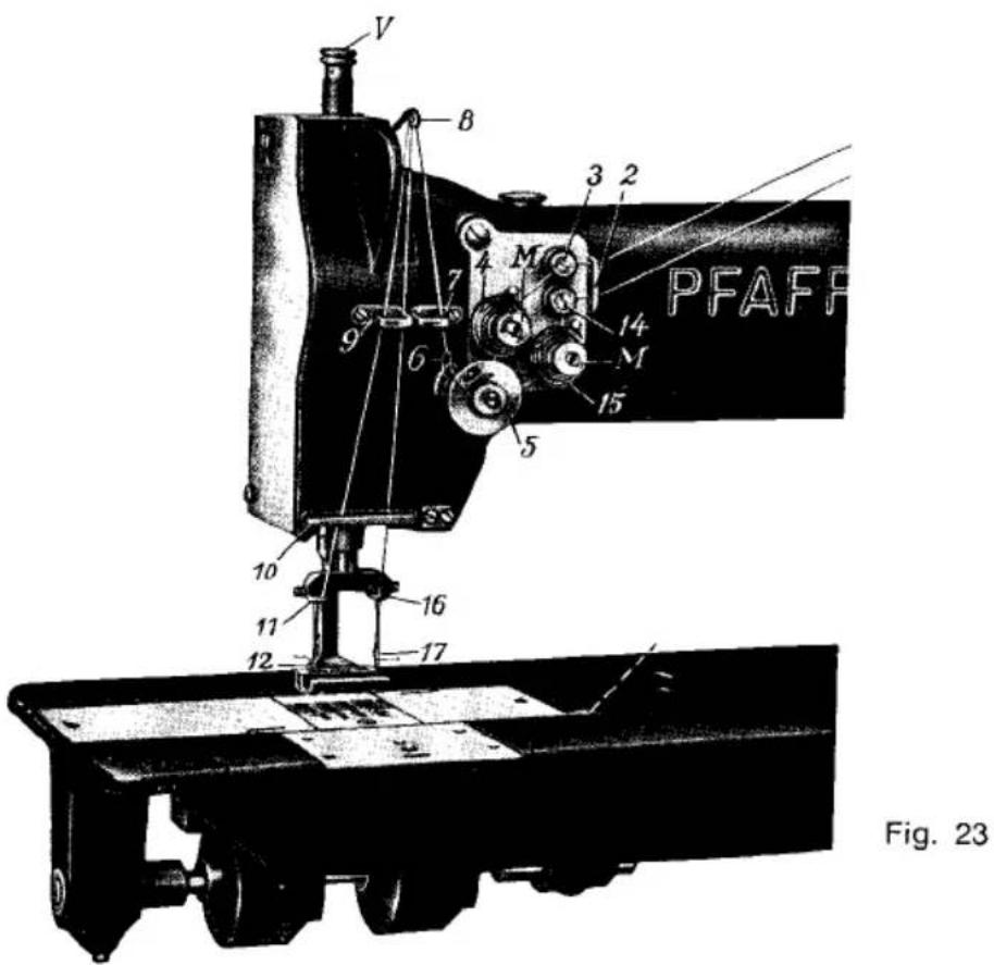
To thread the left needle, pass the thread from the spool on the thread stand through the two upper holes in stud 1 on the machine arm (not shown in Fig. 23), through thread guide 2, around thread retainer 3, around and between tension discs 4, down and around thread controller disc 5, through thread check spring 6, up and through thread guide 7, from right to left through the hole in take-up lever 8, down and through thread guides 9, 10 and 11, and from right to left through the eye of the left needle 12.
To thread the right needle, pass the thread from the second spool on the thread stand through the two lower holes in stud 1 (not shown in Fig. 23), thence to 2, 14, 15, 5, 6, 7, 8, 9, 10 and 16, and from left to right through the eye of the right needle 17.
24. Adjusting the Puller Feed of the Pfaff 148
The Pfaff 148 is equipped with an additional puller feed which is arranged back of the presser foot and, acting in synchronization with the drop feed, ensures even feeding of the material. The lower feed roller is positively driven by the feed rock shaft via a connecting link.
When the presser bar lifter is lowered, the upper feed roller is lowered onto the lower feed roller and the material is firmly gripped between them. To increase the rate of feed of the puller feed for sewing materials that are difficult to handle, loosen the hexagon nut and adjust the position of the connection in the elongated hole of lever X (Fig. 24). Then tighten the hexagon nut securely again. As a result of this adjustment, a stronger pull is exerted on the material back of the presser foot.
To remove the work, the top feed roller is raised by pushing up the lifting lever.
Operation and maintenance of this machine is governed by the general instructions given in this book, except that the additional oiling points shown in Fig. 24 should be supplied with oil.

Fig. 24
Additional Instructions
for Pfaff Machines 141-5-900/05, 142-900/06 and 144-900/06 Fitted with Thread Puller/Trimmer
Since these machines are equipped with Stop motor and electromagnetic thread puller/trimmer, manual needle positioning and thread trimming are completely eliminated.
When you depress the heel of the treadle at the completion of the sewing action, the needle is raised automatically, the needle thread is pulled to the underside of the material and both threads are trimmed. All you have to do to remove the work is raise the presser foot. The thread ends remaining on the underside of the material are long enough to permit them to be pasted down reliably.
The treadle of these machines controls the following functions:
- When you depress the tip of the treadle, the machine starts sewing. The harder you press, the faster the machine will run. (If it is fitted with an inching device, the treadle will also control slow stitch-by-stitch sewing).
- When you relieve the pressure and allow the treadle to return to its neutral position, the needle is lowered for turning corners.
- When you depress the heel of the treadle, the needle is raised to its highest point, the needle thread pulled to the underside of the material, and both threads are trimmed.
- When the treadle is returned to its neutral position again, the needle remains at its highest point.
Additional Instructions
for Pfaff Machines 543 U-12/02 and 543 U-12/03
The Pfaff 543 U-12/02 is a single-needle sewing machine equipped with a two-speed Stop-motor and a roller thread tension, while the Pfaff 543 U-12/03 is fitted with a squirrel-cage induction motor and a disc-type thread tension. Both these machines are equipped with an extra-large vertical rotary hook.
Other than that, the mechanical setup of the Pfaff 543 U-12 is identical with that of the Pfaff 143 flatbed sewing machine so that all operating and servicing instructions given for the latter also apply to the former, the only exception being Chapters 8 and 11.
25. Threading the Needle of the Pfaff 543 U-12
Pass the thread from the spool up and over the thread guide at the top of the thread stand, down and through the hole of the angular thread guide on the machine arm, and through the thread retainer, making sure that the thread enters the slot in the thread retainer stud. Now lead it clockwise around the roller tension of subcl. -12/02 machines or the disc-type tension of subcl. -12/03 machines. Then pass it around the thread controller disc, through the thread check spring, up and through the thread guide, from right to left through the eye in the take-up lever, down and through both thread guides, and from left to right through the needle eye.
R 9697 a
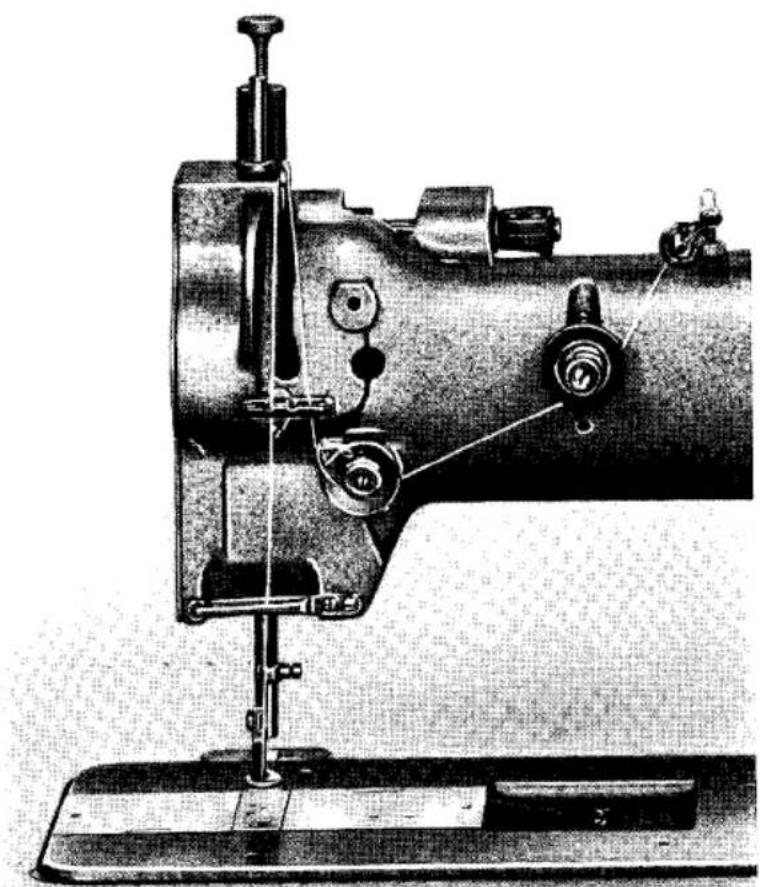
Fig. 25
Additional Instructions
for Pfaff Machines 4141 and 4143
Pfaff machines 4141 and 4143 closely resemble Cl. 141 and 143 machines in their mechanical setup, exterior design and dimensions. Instead of a vertical rotary hook, however, both machines are equipped with a constant-motion rotary looper which moves counter-clockwise. In addition, they are fitted with a thread nipper which, on the Pfaff 4141, is operated by the needle bar crank and, on the Pfaff 4143, by an eccentric arranged on the arm shaft.
Apart from the needle threading instructions, the general instructions given for Pfaff machines 141 and 143 apply to Pfaff machines 4141 and 4143 also. (Since the latter machines are chainstitch sewing machines, bobbin winding naturally is omitted).
Fig. 28
R 6312

28. Upper Threading of the Pfaff 4141
Pass the thread from the spool up to the top thread guide of the thread stand, then down and through both holes in the pin on the machine arm, through the upper hole in the thread guide on the machine arm (as shown in Fig. 28), around the pin, through the lower hole in the thread guide, clockwise around and between the tension discs, from right to left through the hole in the take-up lever, below the lever of the automatic tension, through the lower thread guide and the thread guide on the needle clamp, and from left to right through the needle eye.
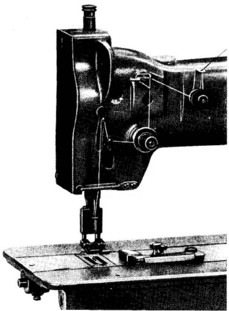
Fig. 29
R 6845a
29. Upper Threading of the Pfaff 4143
Pass the thread from the spool up to the top thread guide of the thread stand, then down and through both holes in the pin on the machine arm, through the hole in the angular bracket of the thread nipper (as shown in Fig. 29), clockwise around and between the thread nipper discs, through the upper hole in the thread guide on the machine arm, around the pin, through the lower hole in the thread guide, clockwise around and between the tension discs, through the thread guide opposite, from right to left through the hole in the take-up lever, through the lower thread guide and the thread guide on the needle clamp, and from left to right through the needle eye.
30. Trouble Shooting
Machine Skips Stitches
Cause
Wrong needle system.
Needle bent.
Needle inserted incorrectly.
Incorrect threading.
Remedy
For correct needle system see Chapter 6.
Insert new needle as instructed in Chapter 7.
Orient needle so that its short groove faces toward the sewing hook.
Thread needle as instructed in Chapters 5, 8 and 24.
Thread Breaks
Cause
For any of the reasons indicated above.
Thread tensions too tight.
Knotty thread.
Needle point blunt or damaged.
Thread snarled up.
Remedy
See remedies listed above.
Regulate tensions as instructed in Chapter 10.
Use high-quality thread only.
Replace needle.
Check upper threading from spool of thread to needle.
Faulty Stitch Formation
Cause
Improper tension.
Wrong needle size and/or thread used.
Pieces of thread between tension discs or under bobbin case tension spring.
Remedy
Regulate tensions as instructed in Chapter 10.
Correlate needle, thread and fabric as shown in table in Chapter 6.
Remove thread and re-adjust tension as instructed in Chapter 10.
Needle Breaks
Cause
Wrong needle system.
Needle bent.
Needle too thin.
Remedy
Insert needle of correct system as instructed in Chapter 6.
Insert new needle.
Insert thicker needle.
Machine Works Heavily
Cause
Lack of oil.
Wrong lubricant.
Hook race obstructed by pieces of thread.
Remedy
Oil machine as instructed in Chapters 3, 13 and 21.
Use only non-resinous and acid-free sewing machine oil.
Try to free the jammed thread as you rock the balance wheel back and forth. If this action should fail, dismantle the sewing hook as instructed in Chapter 13.
Contents
Instructions for Pfaff Machines 141 and 143 . . . . . . . . . 3-14
- General 3
- Fundamentals of Machine Operation 3
- Cleaning and Oiling 4
- Winding the Bobbin . . . . . . . . . . . . . . . 6
- Changing the Bobbin and Threading the Bobbin Case . . . . . . . 7
- Selecting the Correct Needle.
Needle Systems 8
Needle Point Styles 8
Needle and Thread Sizes. 8
- Changing the Needle . . . . . . . . . . . . . . 10
- Threading the Needle 10
- Drawing Up the Bobbin Thread 11
- Regulating the Thread Tensions 11
Adjusting the Upper Tension . . . . . . . . . . . . . 11
Adjusting the Lower Tension . . . . . . . . . . . . . 12 - Regulating the Stitch Length . . . . . . . . . . . . . 12
- Regulating the Pressure on the Material 13
- Cleaning the Sewing Hook 13
- The Safety Clutch 14
Additional Instructions for Pfaff Machines 141-5 and 141-5-225 . . . . 15-17
- Regulating the Stitch Length . . . . . . . . . . . . . 16
- Changing the Feed Gears 17
Additional Instructions for Pfaff Machines 143-5 and 143-5-225 . . . . . 18-20
- Regulating the Stitch Length 18
- Adjusting the Trimmer 19
- Operating the Trimmer 20
Additional Instructions for Pfaff Machines 145 and 155 . . . . . . . 21-23
- Exchanging the Alternating Pressers 21
- Lubricating the Machine . . . . . . . . . . . . . . 23
- Setting the Foot Lift . . . . . . . . . . . . . . 23
Additional Instructions for Pfaff Machines 151 and 153 . . . . . . . . 23
Additional Instructions for Pfaff Machines 142, 144, 146 and 148 . . . . . 24-25
- Threading the Needles 24
- Adjusting the Puller Feed of the Pfaff 148 . . . . . . . . . . . 25
Additional Instructions for Pfaff Machines 141-5-900/05, 142-900/06 and 144-900/06 Fitted with Thread Puller/Trimmer 26
Additional Instructions for Pfaff Machines 543 U-12/02 and 543 U-12/03 . . . . 26
- Threading the Needle of the Pfaff 543 U-12 . . . . . . . . . . 2
Additional Instructions for Pfaff Machines 546 and 548. . . . . . . 28-29
- Setting the Foot Lift.
- Adjusting the Puller Feed . . . . . . . . . . . . . 2
Additional Instructions for Pfaff Machines 4141 and 4143 . . . . . . 30-3
- Upper Threading of the Pfaff 4141 . . . . . . . . . . . . 36
- Upper Threading of the Pfaff 4143 . . . . . . . . . . . . . 3
- Trouble Shooting . . . . . . . . . . . . . . . . 3

- PFAFF
- PEAFF
- INSTRUCTION BOOK
- INSTRUCTIONS
- PFAFF 141 AND 143 MACHINES
- GENERAL
- FUNDAMENTALS OF MACHINE OPERATION
- CLEANING AND OILING
- WINDING THE BOBBIN
- CHANGING THE BOBBIN AND THREADING THE BOBBIN CASE
- SELECTING THE CORRECT NEEDLE
- NEEDLE SYSTEMS
- NEEDLE POINT STYLES
- NEEDLE AND THREAD SIZES
- CHANGING THE NEEDLE
- THREADING THE NEEDLE
- DRAWING UP THE BOBBIN THREAD
- REGULATING THE THREAD TENSIONS
- ADJUSTING THE UPPER TENSION
- ADJUSTING THE LOWER TENSION
- REGULATING THE STITCH LENGTH
- REGULATING THE PRESSURE ON THE MATERIAL
- CLEANING THE SEWING HOOK
- THE SAFETY CLUTCH
- ADDITIONAL INSTRUCTIONS
- CHANGING THE FEED GEARS
- ADJUSTING THE TRIMMER
- OPERATING THE TRIMMER
- EXCHANGING THE ALTERNATING PRESSERS
- LUBRICATING THE MACHINE
- SETTING THE FOOT LIFT
- THREADING THE NEEDLES
- ADJUSTING THE PULLER FEED OF THE PFAFF
- THREADING THE NEEDLE OF THE PFAFF 543 U
- UPPER THREADING OF THE PFAFF
- TROUBLE SHOOTING
- MACHINE SKIPS STITCHES
- CAUSE
- REMEDY
- THREAD BREAKS
- FAULTY STITCH FORMATION
- NEEDLE BREAKS
- MACHINE WORKS HEAVILY
- CONTENTS
- INSTRUCTIONS FOR PFAFF MACHINES 141 AND
- ADDITIONAL INSTRUCTIONS FOR PFAFF MACHINES 141-5 AND
- ADDITIONAL INSTRUCTIONS FOR PFAFF MACHINES 143-5 AND
- ADDITIONAL INSTRUCTIONS FOR PFAFF MACHINES 145 AND
- ADDITIONAL INSTRUCTIONS FOR PFAFF MACHINES 151 AND
- ADDITIONAL INSTRUCTIONS FOR PFAFF MACHINES 142, 144, 146 AND
- ADDITIONAL INSTRUCTIONS FOR PFAFF MACHINES 141-5-900/05, 142-900/06 AND 144-900/06 FITTED WITH THREAD PULLER/TRIMMER
- ADDITIONAL INSTRUCTIONS FOR PFAFF MACHINES 543 U-12/02 AND 543 U
- ADDITIONAL INSTRUCTIONS FOR PFAFF MACHINES 546 AND
- ADDITIONAL INSTRUCTIONS FOR PFAFF MACHINES 4141 AND
Brand : PFAFF
Model : 553
Category : Sewing machine