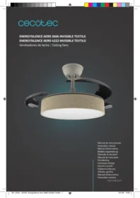
Energysilence Aero 3666 Invisible Textile - Ceiling fan CECOTEC - Free user manual and instructions
Find the device manual for free Energysilence Aero 3666 Invisible Textile CECOTEC in PDF.


| Product type | Ceiling fan |
| Brand | Cecotec |
| Model | Energysilence Aero 3666 Invisible Textile |
| Blade diameter | 132 cm |
| Blade material | High-strength textile |
| Color | White |
| Number of blades | 3 reversible blades |
| Speeds | 6 speeds |
| Power supply | 220-240 V ~ 50 Hz |
| Power | 50 W |
| Noise level | Less than 30 dB (silent) |
| Winter/summer function | Yes, reverse rotation direction |
| Remote control | Yes, with timer and dimmer |
| Installation method | Ceiling mounting (kit included) |
| Rod length | 25 cm (rod included) |
| Tilt angle | 12° |
| Net weight | 5.5 kg |
| Warranty | 3 years |
| Cleaning | Soft dry cloth, do not immerse |
| Spare parts | Available from manufacturer |
Frequently Asked Questions - Energysilence Aero 3666 Invisible Textile CECOTEC
User questions about Energysilence Aero 3666 Invisible Textile CECOTEC
0 question about this device. Answer the ones you know or ask your own.
Ask a new question about this device
Download the instructions for your Ceiling fan in PDF format for free! Find your manual Energysilence Aero 3666 Invisible Textile - CECOTEC and take your electronic device back in hand. On this page are published all the documents necessary for the use of your device. Energysilence Aero 3666 Invisible Textile by CECOTEC.
USER MANUAL Energysilence Aero 3666 Invisible Textile CECOTEC
SAFETY INSTRUCTIONS....4
ESPAÑOL....59
ENGLISH....70
FRANÇAIS....80
DEUTSCH....91
ITALIANO....102
PORTUGUÊS....113
NEDERLANDS....124
POLSKI....135
ČEŠTINA....146
MAGYAR....157
ΕΛΛΗΝΙΚΑ......168
TÜRKÇE....179
العربية....189
CATALÀ....198
FIGURES....209
NOTA
EU01_123702 EnergySilence Aero 3666 Invisible Textile EU01_123703 EnergySilence Aero 4222 Invisible Textile
EN • The coding in this manual is generic and applies to all code variants of the appliance.
Please read these instructions carefully before using the appliance. Keep this instruction manual for future reference or new users.
- This appliance can be used by children aged 8 years and above and people with reduced physical, sensory, or mental capabilities or lack of experience and knowledge if they have been given appropriate supervision or instruction concerning use of the appliance in a safe way and understand the hazards involved. Children must not play with the appliance. Cleaning and user maintenance must not be carried out by children without supervision.
- Keep a minimum distance of 2.3 cm between the fan blades and the floor.
- Keep a minimum distance of 76 cm between the fan blades and the wall or any other object.
- Make sure the appliance is unplugged from the power supply before cleaning or user maintenance.
- This appliance is intended for domestic use only and is not suitable for use in commercial establishments such as bars, restaurants, farms, hotels, motels, and offices.
- Make sure that the mains voltage matches the voltage specified on the appliance rating label and that the wall outlet is earthed.
- Do not use the appliance if its cable or housing are
damaged, nor after it malfunctions or has been dropped or damaged in any way.
- The appliance must be installed in accordance with national wiring regulations.
- Never insert objects or body parts between the rotating fan blades.
- To reduce the risk of injury, attach the fan directly to the support structure of the building as indicated in this manual and use only parts and components provided and recommended by Cecotec.
- Cut off the power completely before installing or repairing the fan to avoid the risk of electric shock.
- The electrical wiring must be in accordance with local regulations.
- The cable must be properly earthed to avoid possible accidents.
- The appliance must be installed in accordance with national wiring regulations.
- Never install the fan in a damp or wet room.
- Be careful when near the rotating fan blades.
- To adjust the speed of the fan blades, only use the means for speed control provided by Cecotec.
- Do not bend the blade-attachment system during the installation or cleaning process.
- Cleaning and maintenance must be carried out according to this instruction manual to make sure the appliance works properly. Turn off and unplug the appliance before cleaning it.
• Make sure the fan is not placed close to curtains or
other objects it may become entangled with.
- In order to ensure your children's safety, please keep all packaging (plastic bags, boxes, polystyrene, etc.) out of their reach.
- It is recommended that two people install the appliance.
- This appliance is designed for indoor use.
Instructions on batteries
- Battery ingestion can cause burns, soft-tissue perforation, and death. It can cause severe burns within two hours of the ingestion.
- In case of battery ingestion, please seek medical attention immediately.
- Do not allow children to replace batteries without adult supervision.
- Do not disassemble, open, or damage the batteries.
- Keep the batteries out of the reach of children. Pay particular attention to small batteries. In case of battery ingestion, please seek medical attention immediately.
- Do not expose batteries to heat or fire. Avoid storage in direct sunlight.
- Do not short-circuit an element or a battery. Do not store batteries in an untidy manner, in a box, or drawer where they can short-circuit each other or be short-circuited by other metal objects.
- Both batteries and cells can leak under extreme conditions. In the event of a battery leak, keep your skin and eyes away from the liquid. If the liquid comes
into contact with skin, wash immediately with soap and water. If the liquid gets into the eyes, rinse them immediately with clean water for at least 10 minutes and seek medical attention. Wear gloves to handle the battery and dispose of it immediately in accordance with local regulations.
- Pay attention to the positive (+) and negative (-) marks on the batteries and the remote-control compartment to ensure they are inserted correctly.
- Do not use any batteries that are not designed for use with the appliance.
- Do not mix batteries of different manufacture, capacity, or size. Supervise children to prevent them from playing with batteries.
• Always buy recommended batteries. - Keep the batteries clean and dry. Wipe the battery terminals with a clean, dry cloth if they become dirty.
- Keep the original instruction manual for future reference.
- Whenever possible, remove the batteries when not in use.
1. Parts and components
Fig. 1
- Mounting bracket
- Hanging ball
- Canopy
- Downrod
- Lower decorative cover
- Hanging piece
- Upper cover
- Decorative textile panel
- Blades
- Triangular piece
- Motor
- Light plate
- Remote control
- Controller
- Lampshade
- Mounting kit
-
Instruction manual
-
Electrical wiring for installation
Note:
The graphics in this manual are schematic representations and may not exactly match the product.
2. Before use
- This appliance comes in a packaging designed to protect it during transport. Remove the appliance from its box. You can keep the original box and other packaging materials in a safe place to prevent damage to the appliance if you need to transport it in the future. If you wish to dispose of the original packaging, make sure all items are recycled properly.
- Check that all parts and components are included and in good condition. If any of them are missing or damaged, please contact Cecotec's Official Technical Support Service immediately.
Box content:
Product
- Remote control
- Instruction manual
- Do not remove the product's serial number in order to keep proper traceability if technical assistance is required.
3. Installation
Height and clearance
Install the fan leaving a minimum distance of 2.3 m between the floor and the blades (9), with sufficient lateral clearance around the blades (9).
WARNING: Disconnect the power supply at the main switchboard and verify absence of voltage before starting. Use a ceiling box suitable for fans and secured to a load-bearing structure.
Securing the mounting bracket (1)
Secure the mounting bracket (1) to the ceiling junction box using the screws from the mounting kit (16). Ensure it is centred and firmly anchored. Figure 2 shows how to anchor depending on whether your ceiling is made of concrete (left) or wood (right).
Preparing the hanging ball (2) and downrod (4)
Loosen the screws on the hanging ball (2) to allow it to slide along the downrod (4).
Remove the bolt/pin and nut from the downrod (4) in the mounting kit (16) and set aside for the securing step. Fig. 3-4
Pass the electrical wiring for installation (17) through the downrod (4).
Assembling the downrod (4) to the motor assembly (11)
Before coupling the downrod (4) to the motor (11), pass the canopy (3) and top cover (7) through the downrod (4) (see Figure 4).
Insert the downrod (4) into the coupling of the hanging piece (6) of the motor (11) and align the bolt hole. Fig. 5.
Insert the bolt from the mounting kit (16) until it passes through both holes, fit the safety pin and tighten the nut. Replace the lateral screws if applicable.
WARNING: Verify that the bolt, its safety device and the screws from the mounting kit (16) are correctly secured. Incorrect assembly may cause the fan to fall.
Positioning the hanging ball (2) in the mounting bracket (1)
Raise the motor assembly (11) + downrod (4) and place the hanging ball (2) on the mounting bracket (1), aligning the groove of the hanging ball (2) with the tab of the mounting bracket (1) to prevent unwanted rotation. Fig. 6.
Assembling the covers and canopy
Position the canopy (3) up to the ceiling to conceal the mounting bracket (1) and the joints of the electrical wiring for installation (17), but do not secure it permanently; secure it after completing the "Electrical connections" section.
After securing the canopy (3) upon completion of connections, fit the lower decorative cover (5) according to the exploded view of the model, ensuring the electrical wiring for installation (17) is not trapped. If applicable, also place the upper cover (7) in its final position.
Installing the light assembly
Connect the light plate (12) to the controller (14) according to the indications in the connections section and secure the light plate (12) to the motor (11) ring using the screws from the mounting kit (16).
Place the lampshade (15) over the light plate (12) and secure it using the indicated method (bayonet turn, magnets or screws, depending on model), checking that it is properly seated. Install the decorative textile panel (8) as shown in Figure 7.
Electrical connections
Earth: Ensure earth continuity between the building installation and all metal parts of the assembly: mounting bracket (1), downrod (4) and motor housing (11).
Connection of controller (14) with motor (11) and light plate (12): make connections following the colour coding indicated in the manual diagram (e.g., white-white, black-black, blue-blue, as shown). Fig. 8
Mains power supply to controller (14): connect live and neutral from the mains to the controller (14) according to the diagram; keep the earth conductor connected to the indicated metal assembly.
Arrange the electrical wiring for installation (17) inside the canopy (3) and covers, without twists or pinch points.
After completing the connections, raise and secure the canopy (3) using the screws from the mounting kit (16); then fit the trims as shown in the parts list (upper cover (7) and/or lower decorative cover (5)). Fig. 9
Fig. 3 key:
- Hanging ball
A. Bolt
B. Nut
Fig. 4 key:
-
Canopy
-
Lower decorative cover
A. Bolt
B. Nut
C. Fork
Fig. 6 key:
- Mounting bracket
D. Tab
E. Hanging ball slot
Fig. 9 key:
- Canopy
F. Canopy screws
4. Operation
Remote control
Fig. 10
- Reverse rotation button (clockwise/anticlockwise)
- Indicator light
- Breeze mode button
- Fan speed buttons (1-6)
- Fan stop button
- Colour temperature change button (warm/neutral/cool cycle)
- Mute button (silences receiver beeps)
- Brightness increase/decrease buttons
- Colour temperature increase/decrease buttons
- Light on/off button
- 2-hour timer button
- 4-hour timer button
Code pairing
Fig. 10
- Cut power to the receiver for 2 minutes. Switch back on; upon hearing a beep, press and hold the fan stop button (5) for 3 seconds until another beep sounds.
● Press the light on/off button (10) once quickly. - Press the fan stop button (5) once again. When the buzzer sounds three times, pairing is complete. Control range: up to 10 metres. In challenging environments, the receiver antenna may be positioned externally to improve reception.
Fan controls
Fig. 10
- Reverse rotation button (1): alternates between clockwise/anticlockwise direction.
- Breeze mode (3): mode that automatically varies speed to simulate natural breeze. Deactivates when selecting a speed (4) or stopping (5).
● Fan speed buttons (4): select levels 1–6.
● Fan stop button (5): stops the fan without affecting the light.
● Mute button (7): hold for 3 seconds to activate/deactivate receiver beeps. - Timer setting 2h (11) / 4h (12): programmes the fan to stop automatically after the selected time.
● LED indicator light (2): confirms command reception (flashing).
Light controls
Fig. 10
● Light on/off button (10): switches the light on or off.
- Brightness increase/decrease (8): short press adjusts in steps; long press adjusts continuously.
- Colour temperature change button (6): cycles quickly between CCT profiles (warm/neutral/cool).
- Continuous tone adjustment (9): K+/K−; short press raises/lowers colour temperature, long press provides continuous transition.
Remote control power and maintenance
● Battery compartment: 2 AA batteries (not included). Check contact and polarity. Remove the batteries if not using the remote for extended periods.
- Do not disassemble the remote control.
Quick troubleshooting
If the remote does not control the receiver: reduce distance ( ≤ 10 m), aim at the receiver, check batteries/contacts. If the problem persists, repeat the pairing process.
5. Cleaning and maintenance
Inspection and retightening
- Normal use may loosen some fixings. A clicking, rattling or vibration sound usually indicates loose screws.
● Every 6 months, check and retighten if necessary:
ENGLISH
● Screws of the mounting bracket (1), hanging ball (2) and downrod (4).
● Fixing screws of the blades (9) to the motor (11).
● Fixing system of the light plate (12) and lampshade (15).
● Tighten firmly without forcing to avoid damaging threads.
Cleaning
- Clean the fan periodically with a soft cloth slightly dampened with mild detergent. Dry afterwards.
- Do not use solvents, alcohol, ammonia, abrasives or scouring pads.
- Remove dust from the blades (9) with a soft cloth or brush. Metal parts are lacquered to prevent staining; do not polish with abrasive compounds.
- Do not spray cleaners directly on the light plate (12) or lampshade (15).
- Decorative textile panel (8): remove dust with a soft vacuum (brush nozzle) or dry cloth. Do not wet or wash it unless the exploded view/label expressly indicates otherwise.
Lubrication
- The fan does not require greasing. The bearings are permanently sealed for quiet, long-lasting operation.
Safety
● Always disconnect the mains supply at the switchboard and verify absence of voltage before carrying out any adjustment, inspection or cleaning.
● Wait for the blades (9) to come to a complete stop before working on the fan.
- If abnormal oscillation persists after retightening, check the condition of the blades and their balance according to the section "The fan wobbles and rocks".
6. Troubleshooting
THE FAN DOES NOT WORK:
- Check all electrical fuses or circuit breakers. Replace fuses if necessary.
- Disconnect the mains supply and check all electrical connections to the fan and at the fan cover switch.
- Ensure the pull-chain switch is on, and change the reverse function by sliding the switch up or down, not in the centre position.
THE FAN MAKES SOME NOISE:
- Using standard dimmer light controls or variable wall speed controls will always cause harmonic distortions or noise. Many fan motors do not operate quietly with variable static controls. If quiet wall control is desired, use only a certified variable speed wall control.
- Always allow a few days of operation for a new fan at medium and high speeds. Try to diagnose the exact location of the noise by listening carefully from different angles (blades, motor, light fitting). Fan noise may originate from the light fitting.
- Ensure that all screws assembled in the fan and light fitting are properly installed and tightened, otherwise return to the previous installation steps to fit them correctly. Check these screws at least once a year as they may gradually loosen over time and cause noise.
- Ensure that the light fitting is secure to the fan and that all shade screws are also firm and hand-tightened. They should not be fitted with pliers or screwdrivers.
- Confirm that the mounting bracket is properly seated in the electrical outlet box.
- Confirm that the connectors inside the switch cover or base do not rub against each other or the wall structure. Wrap with insulating tape if necessary.
- Confirm that the base does not make contact with the ceiling.
- Ensure that the screws from the blade irons to the motor are tight and that the safety washers included for this purpose are used.
● Ensure that all bulbs are properly secured.
THE FAN ROTATES BUT NO AIR FLOWS:
● The fan may be rotating in reverse, so that airflow is directed upwards.
● The room may contain furniture or objects obstructing airflow.
● The fan may be too small for the room.
● Slight movement is considered acceptable and should not be taken as a defect.
- Ensure that the mounting structure is permanently installed to the electrical outlet box/ceiling without any movement, tighten screws if necessary.
- Confirm that all screws securing the blades to the arm and from the blade support arm to the motor are tight. Confirm that the shade screws are secure.
- Some fan movement is normal; however, interchanging pairs of adjacent blades (side to side) to opposite positions may eliminate movement.
- Ensure that the blade attachment screws are uniform despite blade unevenness. Check this point. Each blade should be aligned and adjusted to the same distance
from the ceiling. Measure this distance with a ruler. The exact measurement of these blades simultaneously should be approximately within 1/8". Rotate the fan to perform this operation on the next blade.
7. Technical specifications
Product: EnergySilence Aero 3666 Invisible Textile
Product reference: EU01_123702
Voltage: 220-240 V\~
Frequency: 50/60 Hz
Motor power: 30 W
LED power: 24 W
IP20
T
| Description | Symbol | Value | Unit |
| Maximum fan airflow | F | 54.5 | m^3/min |
| Fan power consumption | P | 28 | W |
| Service value | SV | 1.94 | (m^3/min)/W |
| Power consumption on standby mode | P_SB | 0.15 | W |
| Fan sound power level | L_WA | 45 | dB (A) |
| Maximum air speed | C | 1.52 | m/sec |
| Seasonal electricity consumption | Q | 9.128 | kWh/a |
| Service value measurement standard | IEC 60879 | ||
| Contact details for further information | Cecotec Innovaciones SL.Av. Reyes Católicos, 60, 46910Alfafar, Valencia (Spain) | ||
The power consumption in “off mode” is 0,15 W, measured according to EN 50564:2011 guidelines and European regulations 1275/2008/EC and 801/2013/EC. This measurement is
taken with the appliance connected to the mains without performing any function. The appliance switch/knob was set to the “off” position.
Product: EnergySilence Aero 4222 Invisible Textile
Product reference: EU01_123703
Voltage: 220-240 V\~
Frequency: 50/60 Hz
Motor power: 30 W
LED power: 33 W
IP20
T
| Description | Symbol | Value | Unit |
| Maximum fan airflow | F | 74.1391 | m^3/min |
| Fan power consumption | P | 28 | W |
| Service value | SV | 2.73 | (m^3/min)/W |
| Power consumption on standby mode | P_SB | 0.15 | W |
| Fan sound power level | L_WA | 45 | dB (A) |
| Maximum air speed | C | 1.65 | m/sec |
| Seasonal electricity consumption | Q | 9.128 | kWh/a |
| Service value measurement standard | IEC 60879 | ||
| Contact details for further information | Cecotec Innovaciones SL.Av. Reyes Católicos, 60, 46910Alfafar, Valencia (Spain) | ||
The power consumption in “off mode” is 0,15 W, measured according to EN 50564:2011 guidelines and European regulations 1275/2008/EC and 801/2013/EC. This measurement is taken with the appliance connected to the mains without performing any function. The switch/knob of the appliance was set to the OFF position.
Technical specifications may change without prior notice to improve product quality.
Made in China | Designed in Spain
8. Recycling of electrical and electronic equipment
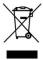
This symbol indicates that, according to the applicable regulations, the product and/or batteries must be disposed of separately from household waste. When this product reaches the end of its service life, you must remove the batteries/accumulators and take it to a collection point designated by local authorities.
For detailed information on how to properly dispose of electrical and electronic equipment and/or the corresponding batteries, consumers should contact their local authorities.
Information regarding national packaging recycling systems and their marking can be found on our website.
Compliance with the above guidelines will help protecting the environment.
9. Technical support and warranty
Cecotec shall be liable to the end user or consumer for any lack of conformity that exists at the time of product delivery under the terms, conditions and deadlines established by applicable regulations.
Repairs should be carried out by qualified personnel.
If at any moment you detect any problem with your product or have any doubt, do not hesitate to contact the official Cecotec Technical Support Service at +34 96 321 07 28.
10. Copyright
The intellectual property rights over the texts in this manual belong to CECOTEC INNOVACIONES, S.L. All rights reserved. The content of this publication may not, either in part or in its entirety, be reproduced, stored in a retrieval system, transmitted or distributed by any means (electronic, mechanical, photocopying, recording or similar) without prior authorisation from CECOTEC INNOVACIONES, S.L.
11. Simplified EU Declaration of Conformity

Cecotec Innovaciones hereby declares that this appliance complies with the essential requirements and other relevant provisions of the regulations applicable in the European Union. This appliance has been designed, manufactured and tested in compliance with required safety and quality standards. The full text of the EU Declaration of Conformity can be found on the following website:
https://cecotec.es/es/information/declaration-of-conformity
FRANÇAIS
https://storececotec.it/it/information/declaration-of-conformity
PORTUGUÊS
https://cecotec.es/es/information/declaration-of-conformity
POLSKI
WENTYLATOR JEST GŁOŚNY:
https://cecotec.es/es/information/declaration-of-conformity
ČEŠTINA
https://cecotec.es/es/information/declaration-of-conformity
ΕΛΛΗΝΙΚΑ
ΕΛΛΗΝΙΚΑ
https://cecotec.es/es/information/declaration-of-conformity
.1 قوس التثبيت
.2. كرة التعليم
.3.Floroun
.4. القضيب المركزي
.5. غطاء زخرفي سفلي
.6 رأس متدلي
.7 . الغطاء العلوي
https://cecotec.es/es/information/declaration-of-conformity
CATALÀ
1. Peces i components
Figura 1
https://cecotec.es/es/information/declaration-of-conformity
FIGURES
FIG 1:

FIG 2:

- NOTA
- Instructions on batteries
- Parts and components
- Fig. 1
- Note:
- Before use
- Box content:
- Installation
- Height and clearance
- Securing the mounting bracket (1)
- Preparing the hanging ball (2) and downrod (4)
- Positioning the hanging ball (2) in the mounting bracket (1)
- Assembling the covers and canopy
- Electrical connections
- Operation
- Remote control
- Code pairing
- Fan controls
- Light controls
- Remote control power and maintenance
- Quick troubleshooting
- Cleaning and maintenance
- Inspection and retightening
- ENGLISH
- Cleaning
- Lubrication
- Safety
- Troubleshooting
- THE FAN DOES NOT WORK:
- THE FAN MAKES SOME NOISE:
- THE FAN ROTATES BUT NO AIR FLOWS:
- Technical specifications
- Recycling of electrical and electronic equipment
- Technical support and warranty
- Copyright
- Simplified EU Declaration of Conformity
- FRANÇAIS
- PORTUGUÊS
- POLSKI
- WENTYLATOR JEST GŁOŚNY:
- ČEŠTINA
- ΕΛΛΗΝΙΚΑ
- CATALÀ
- Peces i components
- Figura 1
Brand : CECOTEC
Model : Energysilence Aero 3666 Invisible Textile
Category : Ceiling fan