
ProLiant DL320 G6 - Server HP - Free user manual and instructions
Find the device manual for free ProLiant DL320 G6 HP in PDF.


| Product Type | Server |
| Model | HP ProLiant DL320 G6 |
| Form Factor | 1U Rack |
| Dimensions (W x D x H) | 42.6 x 68.6 x 4.3 cm (16.8 x 27.0 x 1.7 in) |
| Weight | 14.5 kg (32 lbs) |
| Processor | Intel Xeon E5500/E5600 series, up to 2.93 GHz |
| Memory | 6 x DIMM slots, DDR3 ECC, up to 48 GB |
| Storage | 4 x 3.5" hot-swap SATA/SAS bays |
| Power Supply | 460 W or 750 W redundant optional |
| Networking | Dual Gigabit Ethernet (NC375i) |
| Remote Management | HP iLO 2 (Integrated Lights-Out 2) |
| RAID Support | Smart Array P410 or P212 controller |
| Expansion Slots | 1 x PCIe x16, 1 x PCIe x8 |
| Cooling | 4 x hot-swappable fans |
| Operating Temperature | 10°C to 35°C (50°F to 95°F) |
| Operating Humidity | 10% to 90% non-condensing |
| Maintenance | Cold swap components; replaceable fan and power supply |
| Safety | Product is certified; follow ESD precautions |
| Spare Parts | Available via HP partner network |
| Repairability | Moderate; requires trained personnel |
Frequently Asked Questions - ProLiant DL320 G6 HP
User questions about ProLiant DL320 G6 HP
0 question about this device. Answer the ones you know or ask your own.
Ask a new question about this device
Download the instructions for your Server in PDF format for free! Find your manual ProLiant DL320 G6 - HP and take your electronic device back in hand. On this page are published all the documents necessary for the use of your device. ProLiant DL320 G6 by HP.
USER MANUAL ProLiant DL320 G6 HP
HP ProLiant DL320 G6 Server User Guide

© Copyright 2009, 2010 Hewlett-Packard Development Company, L.P.
The information contained herein is subject to change without notice. The only warranties for HP products and services are set forth in the express warranty statements accompanying such products and services. Nothing herein should be construed as constituting an additional warranty. HP shall not be liable for technical or editorial errors or omissions contained herein.
Microsoft, Windows, and Windows Server are U.S. registered trademarks of Microsoft Corporation.
Intended audience
This document is for the person who installs, administers, and troubleshoots servers and storage systems. HP assumes you are qualified in the servicing of computer equipment and trained in recognizing hazards in products with hazardous energy levels.
Contents
Component identification....7
Front panel components....7
Front panel LEDs and buttons....8
SAS and SATA device numbers 8
Rear panel components 9
Rear panel LEDs and buttons 9
PCI expansion slot definitions 10
System board components 10
System maintenance switch 11
System board LEDs....13
System LEDs and internal health LED combinations....14
Fan locations....14
Operations.... 16
Power up the server 16
Power down the server 16
Remove the server from the rack 16
Remove the access panel 17
Remove the air baffle....17
Remove the PCI riser board assembly....17
Install the PCI riser board assembly....18
Setup....20
Optional installation services....20
Rack planning resources 20
Optimum environment....21
Space and airflow requirements 21
Temperature requirements 21
Power requirements....22
Electrical grounding requirements 22
Rack warnings 23
Identifying the server shipping carton contents....23
Installing hardware options 23
Installing the server into the rack....24
Installing the operating system 25
Powering up and configuring the server....25
Registering the server....25
Hardware options installation.... 26
Introduction 26
Memory options....26
Memory subsystem architecture 26
Single-, dual-, and quad-rank DIMMs 27
DIMM identification....27
Memory configurations 28
General DIMM slot population guidelines 29
Installing a DIMM....31
Redundant hot-plug power supply option 32
Hard drive options 32
Hard drive guidelines 32
Removing a hard drive blank 33
Removing a hard drive 33
Installing a hard drive....34
Optical drive option 35
Dedicated iLO 2 port module option ....37
Expansion board option....38
PCI-X riser board option 39
Storage controller option....40
Flash-backed write cache capacitor pack option....41
Battery-backed write cache battery pack option....42
HP Trusted Platform Module option 44
Installing the Trusted Platform Module board 45
Retaining the recovery key/password....46
Enabling the Trusted Platform Module....47
Cabling 48
Cabling overview....48
Non-redundant power supply cabling....48
Optional non-redundant high-efficiency power supply cabling 48
Optional redundant power supply cabling....49
Optional Common Slot Power Supply cabling....49
SATA cabling 50
Optional SAS controller cabling 50
BBWC battery pack or FBWC capacitor pack cabling to an optional controller....51
Configuration and utilities 52
Configuration tools....52
SmartStart software 52
HP ROM-Based Setup Utility 53
Array Configuration Utility 55
Option ROM Configuration for Arrays....55
HP ProLiant Essentials Rapid Deployment Pack 56
Re-entering the server serial number and product ID 56
Management tools....56
Automatic Server Recovery....56
ROMPaq utility....57
Integrated Lights-Out 2 technology ....57
Erase Utility 57
StorageWorks library and tape tools....58
HP Systems Insight Manager 58
Management Agents 58
Redundant ROM support....58
USB support 59
Internal USB functionality ....59
Internal SD support....59
Diagnostic tools 59
HP Insight Diagnostics 59
HP Insight Diagnostics survey functionality 60
Integrated Management Log....60
Array Diagnostic Utility....60
HP Insight Remote Support software 60
HP Insight Server Migration software for ProLiant....61
Keeping the system current....61
Drivers 61
ProLiant Support Packs....62
Operating system version support 62
System Online ROM flash component utility 62
Change control and proactive notification 62
Care Pack 62
Troubleshooting 63
Troubleshooting resources 63
Pre-diagnostic steps 63
Important safety information....63
Symptom information....65
Prepare the server for diagnosis....66
Loose connections 66
Service notifications....67
Troubleshooting flowcharts....67
Start diagnosis flowchart....67
General diagnosis flowchart....68
Server power-on problems flowchart 70
POST problems flowchart....73
OS boot problems flowchart....74
Server fault indications flowchart 76
POST error messages and beep codes 78
Battery replacement 79
Regulatory compliance notices 81
Regulatory compliance identification numbers....81
Federal Communications Commission notice....81
FCC rating label 81
Class A equipment 81
Class B equipment....81
Declaration of conformity for products marked with the FCC logo, United States only....82
Modifications....82
Cables 82
Canadian notice (Avis Canadien) 83
European Union regulatory notice....83
Disposal of waste equipment by users in private households in the European Union....83
Japanese notice 84
BSMI notice 84
Korean notice 85
Chinese notice 85
Laser compliance 85
Battery replacement notice 85
Taiwan battery recycling notice 86
Power cord statement for Japan 86
Electrostatic discharge 87
Preventing electrostatic discharge 87
Grounding methods to prevent electrostatic discharge....87
Specifications 88
Environmental specifications....88
Mechanical specifications 88
Power supply specifications....89
Technical support....92
Before you contact HP 92
HP contact information....92
Customer Self Repair 92
Acronyms and abbreviations.... 100
Index 102
Component identification
Front panel components
- LFF models

| Item Description |
| 1 Optical drive blank |
| 2 Serial label pull tab |
| 3 USB connectors (2) |
| 4 Hard drive bays |
- SFF models

| Item Description |
| 1 Optical drive blank |
| 2 Serial label pull tab |
| 3 USB connectors (2) |
| 4 Hard drive bays |
Front panel LEDs and buttons
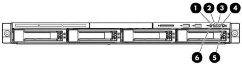
| Item Description Status | ||
| 1 Internal health LED Green = System | health is normal.Amber = System health is degraded. To identify the component in a degraded state, see "System board LEDs (on page 13)."Red = System health is critical. To identify the component in a critical state, see "System board LEDs (on page 13)."Off = System health is normal (when in standby mode). | |
| 2 NIC | 1 link/activity LED Green = Network link exists.Flashing green = Network link and activity exist.Off = No network link exists.If power is off, view the LEDs on the RJ-45 connector. See "Rear panel LEDs and buttons (on page 9)." | |
| 3 NIC | 2 link/activity LED Green = Network link exists.Flashing green = Network link and activity exist.Off = No network link exists.If power is off, view the LEDs on the RJ-45 connector. See "Rear panel LEDs and buttons (on page 9)." | |
| 4 | Drive activity LED | Green = Drive activity is normal.Off = No drive activity exists. |
| 5 | Power On/Standby button and system power LED | Green = Normal (system on)Amber = System is in standby, but power is still applied.Off = Power cord is not attached or the power supply has failed. |
| 6 | UID button/LED | Blue = Identification is activated.Flashing blue = System is being managed remotely.Off = Identification is deactivated. |
SAS and SATA device numbers

Rear panel components
For this server model, PCI expansion slots 1-3 and 6 are reserved.

| Item | Description |
| 1 | Power cord connector |
| 2 | Mouse connector |
| 3 | 10/100/1000 NIC 1 connector/shared iLO 2 management port |
| 4 | 10/100/1000 NIC 2 connector |
| 5 | Serial connector |
| 6 | Slot 5 PCIe2 x16 (4, 2, 1) |
| 7 | Slot 4 PCIe2 x16 (16, 8, 4, 1) |
| 8 | UID button/LED |
| 9 | Dedicated iLO 2 management port (optional) |
| 10 | Video connector |
| 11 | USB connectors (2) |
| 12 | Keyboard connector |
Rear panel LEDs and buttons

| Item Description Status | ||
| 1 UID button/LED Blue = Activated | Flashing = System is being managed remotely.Off = Deactivated | |
| 2 | NIC/iLO 2 link | Green or flashing green = Activity exists.Off = No activity exists. |
| 3 | NIC/iLO 2 activity | Green = Link exists.Off = No link exists. |
PCI expansion slot definitions
For this server model, PCI expansion slots 1-3 and 6 are reserved.
| Slot | Type | Length | Connector | Interconnect |
| 4 | PCI Express | Full | x16 | x16 |
| 4 | Optional PCI-X | Full | 133 MHz/3.3 V | 64 bit |
| 5 | PCI Express | Half | x16 | x4 |
System board components
For this server, some system board slots and connectors are reserved.
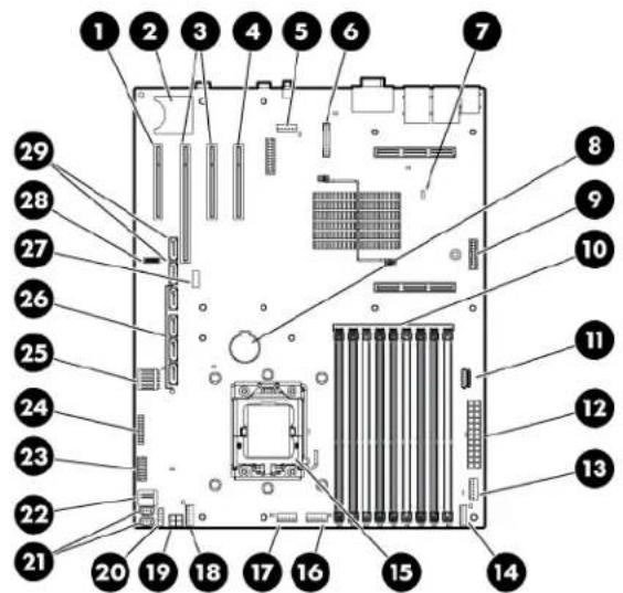
| Item | Description |
| 1 | Reserved |
| 2 | SD card connector |
| 3 | PCIe riser board connectors |
| 4 | Reserved |
| 5 | Fan 6 connector (reserved) |
| Item Description | |
| 6 Dedicated iLO 2 module connector (optional) | |
| 7 NMI jumper | |
| 8 System battery | |
| 9 TPM connector | |
| 10 DIMM slots 1-9 | |
| 11 Reserved | |
| 12 System power connector | |
| 13 Fan 1 connector | |
| 14 Fan 2 connector | |
| 15 Processor socket | |
| 16 Fan 3 connector | |
| 17 Fan 4 connector | |
| 18 Fan 5 connector* | |
| 19 Power connector | |
| 20 Front USB connector | |
| 21 Hard drive backplane connector | |
| 22 USB tape drive connector | |
| 23 Redundant power supply connector | |
| 24 Front panel connector | |
| 25 Fan 7 connector | |
| 26 SATA connectors 1-4 (hard drives) | |
| 27 Hard drive backplane connector | |
| 28 System maintenance switch | |
| 29 SATA connectors 5-6 (optical drives)** | |
* Fan 5 is only available in CTO models of this server.
**The server supports one optical drive that can be connected to either SATA connector 5 or SATA connector 6.
System maintenance switch
| Position Default Function | ||
| S1 | Off | Off = iLO 2 security is enabledOn = iLO 2 security is disabled |
| S2 Off Off = | Normal operation | On = RBSU will not commit any configuration changes* |
| S3 Off Reserved | ||
| S4 Off Reserved | ||
| S5 | Off | Off = Power-on password enabledOn = Power-on password disabled* |
| S6 Off Off = | Normal operation | On = BIOS will clear CMOS and NVRAM* |
| S7 Off Reserved | ||
| S8 Off Reserved | ||
* "On" activates the function.
NMI functionality
An NMI crash dump enables administrators to create crash dump files when a system is hung and not responding to traditional debug mechanisms.
Crash dump log analysis is an essential part of diagnosing reliability problems, such as hangs in operating systems, device drivers, and applications. Many crashes freeze a system, and the only available action for administrators is to cycle the system power. Resetting the system erases any information that could support problem analysis, but the NMI feature preserves that information by performing a memory dump before a hard reset.
To force the OS to invoke the NMI handler and generate a crash dump log, the administrator can do any of the following:
• Short the NMI jumper pins
- Press the NMI switch
• Use the iLO Virtual NMI feature
For additional information, see the whitepaper on the HP website
(http://h20000.www2.hp.com/bc/docs/support/SupportManual/c00797875/c00797875.pdf).
System board LEDs

| Item LED description Status | ||
| 1 | Fan 6 failure (reserved) | — |
| 2 Power supply Off = No AC power or failed power supplyGreen = Power supply is on and functioning. | ||
| 3 Overtemperature | Amber = System has reached a cautionary or critical temperature level.Off = Normal | |
| 4 | Fan 1 failure | Amber = Fan has failed or is missing.Off = Normal |
| 5 | Fan 2 failure | Amber = Fan has failed or is missing.Off = Normal |
| 6 | DIMM failure (1-9) | Amber = DIMM has failed or is missing.Off = Normal |
| 7 | Fan 3 failure | Amber = Fan has failed or is missing.Off = Normal |
| 8 | Fan 4 failure | Amber = Fan has failed or is missing.Off = Normal |
| 9 | Fan 5 failure* | Amber = Fan has failed or is missing.Off = Normal |
| 10 | Fan 7 failure | Amber = Fan has failed or is missing.Off = Normal |
| 11 | Processor failure | Amber = Processor has failed.Off = Normal |
* Fan 5 is only available in CTO models of this server.
System LEDs and internal health LED combinations
When the internal health LED on the front panel illuminates either amber or red, the server is experiencing a health event. Combinations of illuminated system LEDs and the internal health LED indicate system status.
The front panel health LEDs indicate only the current hardware status. In some situations, HP SIM may report server status differently than the health LEDs because the software tracks more system attributes.
| System LED and Color | Internal Health LED Color | Status |
| Processor failure (amber) | Red | One or more of the following conditions may exist:• Processor has failed.• Processor is not installed in the socket.• Processor is unsupported.• ROM detects a failed processor during POST. |
| Amber | Processor is in a pre-failure condition. | |
| DIMM failure, slot X (amber) | Red | • DIMM in slot X has failed.• DIMM in slot X is an unsupported type, and no valid memory exists in another channel. |
| Amber | • DIMM in slot X has reached the single-bit correctable error threshold.• DIMM in slot X is in a pre-failure condition.• DIMM in slot X is an unsupported type, but valid memory exists in another channel. | |
| DIMM failure, all slots in one channel (amber) | Red | No valid or usable memory is installed in the system. |
| Amber | • The entire channel is not populated.• DIMMs do not match within the channel, but other valid memory is available. | |
| Overtemperature (amber) | Amber | The Health Driver has detected a cautionary temperature level. |
| Red | The server has detected a hardware critical temperature level. | |
| Fan module (amber) Red | The minimum fan requirements are not being met in one or more of the fan modules. One or more fans have failed or are missing. | |
| Power supply (amber) | Red | One or more of the following conditions may exist:• There is no AC power.• The power supply has failed. |
| Amber There is a power supply mismatch at POST. | ||
Fan locations
Fan 5 is only available in CTO models of this server.
Fan 6 is reserved.

Operations
Power up the server
To power up the server, press the Power On/Standby button.
Power down the server

WARNING: To reduce the risk of personal injury, electric shock, or damage to the equipment, remove the power cord to remove power from the server. The front panel Power On/Standby button does not completely shut off system power. Portions of the power supply and some internal circuitry remain active until AC power is removed.

IMPORTANT: If installing a hot-plug device, it is not necessary to power down the server.
- Back up the server data.
- Shut down the operating system as directed by the operating system documentation.
NOTE: If the operating system automatically places the server in Standby mode, omit the next step.
- Press the Power On/Standby button to place the server in Standby mode. When the server activates Standby power mode, the system power LED changes to amber.

IMPORTANT: Pressing the UID button illuminates the blue UID LEDs on the front and rear panels. In a rack environment, this feature facilitates locating a server when moving between the front and rear of the rack.
- Disconnect the power cords.
The system is now without power.
Remove the server from the rack

WARNING: The server is not attached to the rack mounting rails. To avoid potential damage to the server and personal injury, always support the server with both hands when removing it from the rack.
To remove the server from an HP, Compaq branded, telco, or third-party rack:
- Power down the server (on page 16).
- Disconnect all peripheral cables and power cords from the server rear panel.
- Loosen the thumbscrews that secure the server faceplate to the front of the rack.
-
Remove the server from the rack. For more information, see the documentation that ships with the rack mounting option.
-
Place the server on a sturdy, level surface.
Remove the access panel
!
WARNING: To reduce the risk of personal injury from hot surfaces, allow the drives and the internal system components to cool before touching them.
△
CAUTION: Do not operate the server for long periods with the access panel open or removed. Operating the server in this manner results in improper airflow and improper cooling that can lead to thermal damage.
To remove the component:
-
Power down the server (on page 16).
-
Remove the server from the rack (on page 16).
-
Open the latch, slide the access panel to the rear of the chassis, and remove the access panel. If the latch is locked, use a T-15 Torx screwdriver to unlock the latch.
Remove the air baffle
To remove the component:
- Power down the server (on page 16).
- Remove the server from the rack (on page 16).
- Remove the access panel (on page 17).
- Remove the air baffle.

To replace the component, reverse the removal procedure.
Remove the PCI riser board assembly
△
CAUTION: To prevent damage to the server or expansion boards, power down the server and remove all AC power cords before removing or installing the PCI riser board assembly.
- Power down the server (on page 16).
- Remove the server from the rack (on page 16).
- Remove the access panel (on page 17).
- Disconnect all internal cables connected to existing expansion boards.
- Remove the PCI riser board assembly:
a. Remove the T-10 screw.
b. Remove the T-15 screws.
c. Remove the riser board assembly.

Install the PCI riser board assembly
△
CAUTION: To prevent damage to the server or expansion boards, power down the server and remove all AC power cords before removing or installing the PCI riser board assembly.
- Install the PCI riser board assembly.

- Connect any internal cables for expansion boards.
- Install the access panel.
- Install the server into the rack.
Setup
Optional installation services
Delivered by experienced, certified engineers, HP Care Pack services help you keep your servers up and running with support packages tailored specifically for HP ProLiant systems. HP Care Packs let you integrate both hardware and software support into a single package. A number of service level options are available to meet your needs.
HP Care Pack Services offer upgraded service levels to expand your standard product warranty with easy-to-buy, easy-to-use support packages that help you make the most of your server investments. Some of the Care Pack services are:
- Hardware support
- 6-Hour Call-to-Repair
- 4-Hour 24x7 Same Day
- 4-Hour Same Business Day
- Software support
- Microsoft®
- Linux
- HP ProLiant Essentials (HP SIM and RDP)
VMWare - Solaris
• Integrated hardware and software support
- Critical Service
- Proactive 24
- Support Plus
- Support Plus 24
• Startup and implementation services for both hardware and software
For more information on Care Packs, refer to the HP website (http://www.hp.com/hps/carepack/servers/cp_proliant.html).
Rack planning resources
The rack resource kit ships with all HP branded or Compaq branded 9000, 10000, and H9 series racks. For more information on the content of each resource, refer to the rack resource kit documentation.
If you intend to deploy and configure multiple servers in a single rack, refer to the white paper on high-density deployment at the HP website (http://www.hp.com/products/servers/platforms).
Optimum environment
When installing the server in a rack, select a location that meets the environmental standards described in this section.
Space and airflow requirements
To allow for servicing and adequate airflow, observe the following space and airflow requirements when deciding where to install a rack:
- Leave a minimum clearance of 63.5 cm (25 in) in front of the rack.
- Leave a minimum clearance of 76.2 cm (30 in) behind the rack.
- Leave a minimum clearance of 121.9 cm (48 in) from the back of the rack to the back of another rack or row of racks.
HP servers draw in cool air through the front door and expel warm air through the rear door. Therefore, the front and rear rack doors must be adequately ventilated to allow ambient room air to enter the cabinet, and the rear door must be adequately ventilated to allow the warm air to escape from the cabinet.

CAUTION: To prevent improper cooling and damage to the equipment, do not block the ventilation openings.
When vertical space in the rack is not filled by a server or rack component, the gaps between the components cause changes in airflow through the rack and across the servers. Cover all gaps with blanking panels to maintain proper airflow.

CAUTION: Always use blanking panels to fill empty vertical spaces in the rack. This arrangement ensures proper airflow. Using a rack without blanking panels results in improper cooling that can lead to thermal damage.
The 9000 and 10000 Series Racks provide proper server cooling from flow-through perforations in the front and rear doors that provide 64 percent open area for ventilation.

CAUTION: When using a Compaq branded 7000 Series rack, you must install the high airflow rack door insert [P/N 327281-B21 (42U) or P/N 157847-B21 (22U)] to provide proper front-to-back airflow and cooling.

CAUTION: If a third-party rack is used, observe the following additional requirements to ensure adequate airflow and to prevent damage to the equipment:
- Front and rear doors—If the 42U rack includes closing front and rear doors, you must allow 5,350 sq cm (830 sq in) of holes evenly distributed from top to bottom to permit adequate airflow (equivalent to the required 64 percent open area for ventilation).
- Side—The clearance between the installed rack component and the side panels of the rack must be a minimum of 7 cm (2.75 in).
Temperature requirements
To ensure continued safe and reliable equipment operation, install or position the system in a well-ventilated, climate-controlled environment.
The maximum recommended ambient operating temperature (TMRA) for most server products is 35° C ( 95° F). The temperature in the room where the rack is located must not exceed 35° C ( 95° F).

CAUTION: To reduce the risk of damage to the equipment when installing third-party options:
- Do not permit optional equipment to impede airflow around the server or to increase the internal rack temperature beyond the maximum allowable limits.
- Do not exceed the manufacturer's TMRA.
Power requirements
Installation of this equipment must comply with local and regional electrical regulations governing the installation of information technology equipment by licensed electricians. This equipment is designed to operate in installations covered by NFPA 70, 1999 Edition (National Electric Code) and NFPA-75, 1992 (code for Protection of Electronic Computer/Data Processing Equipment). For electrical power ratings on options, refer to the product rating label or the user documentation supplied with that option.

WARNING: To reduce the risk of personal injury, fire, or damage to the equipment, do not overload the AC supply branch circuit that provides power to the rack. Consult the electrical authority having jurisdiction over wiring and installation requirements of your facility.

CAUTION: Protect the server from power fluctuations and temporary interruptions with a regulating uninterruptible power supply (UPS). This device protects the hardware from damage caused by power surges and voltage spikes and keeps the system in operation during a power failure.
When installing more than one server, you may need to use additional power distribution devices to safely provide power to all devices. Observe the following guidelines:
• Balance the server power load between available AC supply branch circuits.
- Do not allow the overall system AC current load to exceed 80 percent of the branch circuit AC current rating.
- Do not use common power outlet strips for this equipment.
- Provide a separate electrical circuit for the server.
Electrical grounding requirements
The server must be grounded properly for proper operation and safety. In the United States, you must install the equipment in accordance with NFPA 70, 1999 Edition (National Electric Code), Article 250, as well as any local and regional building codes. In Canada, you must install the equipment in accordance with Canadian Standards Association, CSA C22.1, Canadian Electrical Code. In all other countries, you must install the equipment in accordance with any regional or national electrical wiring codes, such as the International Electrotechnical Commission (IEC) Code 364, parts 1 through 7. Furthermore, you must be sure that all power distribution devices used in the installation, such as branch wiring and receptacles, are listed or certified grounding-type devices.
Because of the high ground-leakage currents associated with multiple servers connected to the same power source, HP recommends the use of a PDU that is either permanently wired to the building's branch circuit or includes a nondetachable cord that is wired to an industrial-style plug. NEMA locking-style plugs or those complying with IEC 60309 are considered suitable for this purpose. Using common power outlet strips for the server is not recommended.
Rack warnings

WARNING: To reduce the risk of personal injury or damage to the equipment, be sure that:
• The leveling jacks are extended to the floor.
- The full weight of the rack rests on the leveling jacks.
- The stabilizing feet are attached to the rack if it is a single-rack installation.
- The racks are coupled together in multiple-rack installations.
- Only one component is extended at a time. A rack may become unstable if more than one component is extended for any reason.

WARNING: To reduce the risk of personal injury or equipment damage when unloading a rack:
- At least two people are needed to safely unload the rack from the pallet. An empty 42U rack can weigh as much as 115 kg (253 lb), can stand more than 2.1 m (7 ft) tall, and may become unstable when being moved on its casters.
- Never stand in front of the rack when it is rolling down the ramp from the pallet. Always handle the rack from both sides.
Identifying the server shipping carton contents
Unpack the server shipping carton and locate the materials and documentation necessary for installing the server. All the rack mounting hardware necessary for installing the server into the rack is included with the rack or the server.
The contents of the server shipping carton include:
Server
- Printed setup documentation, Documentation CD, and software products
Power cord
- Rack mounting hardware kit and documentation
In addition to these supplied items, you may need:
• Application software CDs or diskettes
- Options to be installed
T-10/T-15 Torx screwdriver
Installing hardware options
Install any hardware options before initializing the server. For options installation information, refer to the option documentation. For server-specific information, refer to "Hardware options installation (on page 26)."
Installing the server into the rack
To install the server into a rack with square, round, or threaded holes, refer to the instructions that ship with the rack hardware kit.
If you are installing the server into a telco rack, order the appropriate option kit at the RackSolutions.com website (http://www.racksolutions.com/hp). Follow the server-specific instructions on the website to install the rack brackets.
Use the following information when connecting peripheral cables and power cords to the server.

WARNING: To reduce the risk of electric shock, fire, or damage to the equipment, do not plug telephone or telecommunications connectors into RJ-45 connectors.
For this server model, PCI expansion slots 1-3 and 6 are reserved.

| Item | Description |
| 1 | Power cord connector |
| 2 | Mouse connector |
| 3 | 10/100/1000 NIC 1 connector/shared iLO 2 management port |
| 4 | 10/100/1000 NIC 2 connector |
| 5 | Serial connector |
| 6 | Slot 5 PCIe2 x16 (4, 2, 1) |
| 7 | Slot 4 PCIe2 x16 (16, 8, 4, 1) |
| 8 | UID button/LED |
| 9 | Dedicated iLO 2 management port (optional) |
| 10 | Video connector |
| 11 | USB connectors (2) |
| 12 | Keyboard connector |
Installing the operating system
To operate properly, the server must have a supported OS. For the latest information on OS support, refer to the HP website (http://www.hp.com/go/supportos).
Two methods are available to install an OS on the server:
- SmartStart assisted installation—Insert the SmartStart CD into the CD-ROM drive and reboot the server.
- Manual installation—Insert the OS CD into the CD-ROM drive and reboot the server. This process may require you to obtain additional drivers from the HP website (http://www.hp.com/support).
Follow the on-screen instructions to begin the installation process.
NOTE: For SATA RAID configuration, a driver diskette must be created.
For information on using these installation paths, refer to the SmartStart installation poster in the HP ProLiant Essentials Foundation Pack, included with the server.
Powering up and configuring the server

IMPORTANT: The F8 key is available only when a supported storage controller is installed in the server.
To power up the server, press the Power On/Standby button.
While the server boots, RBSU and the ORCA utility are automatically configured to prepare the server for OS installation.
- Press the F8 key when prompted during the array controller initialization to configure the array controller using ORCA. The array controller defaults to RAID 0 with one drive installed and RAID 1 with more than one drive installed.
- Press the F9 key, when prompted during the boot process, to access RBSU and change the server settings (such as language and operating system). The system is set up by default for the English language.
For more information on the automatic configuration, refer to the HP ROM-Based Setup Utility User Guide located on the Documentation CD.
Registering the server
To register the server, refer to the HP Registration website (http://register.hp.com).
Hardware options installation
Introduction
If more than one option is being installed, read the installation instructions for all the hardware options and identify similar steps to streamline the installation process.

WARNING: To reduce the risk of personal injury from hot surfaces, allow the drives and the internal system components to cool before touching them.

CAUTION: To prevent damage to electrical components, properly ground the server before beginning any installation procedure. Improper grounding can cause electrostatic discharge.
Memory options

IMPORTANT: This server does not support mixing RDIMMs and UDIMMs. Attempting to mix these two types causes the server to halt during BIOS initialization.
The memory subsystem in this server can support RDIMMs or UDIMMs. Both types are referred to as DIMMs when the information applies to both types. When specified as RDIMM or UDIMM, the information applies to that type only. All memory installed in the server must be the same type.
The server supports the following DIMM speeds:
• Single- and dual-rank PC3-10600 (DDR-1333) DIMMs operating at 1333 and 1066 MHz
• Quad-rank PC3-8500 (DDR-1067) DIMMs operating at 1066 MHz
Depending on the processor model, the number of DIMMs installed, and whether UDIMMs or RDIMMs are installed, the memory clock speed may be reduced to 1066 or 800 MHz. For more information on the effect of DIMM slot population, see "General DIMM slot population guidelines (on page 29)."
Memory subsystem architecture
The memory subsystem in this server is divided into channels. Each processor supports three channels, and each channel supports three DIMM slots, as shown in the following table.
| Channel Slot Slot number | ||
| 1 G | 1 | |
| D | 2 | |
| A | 3 | |
| 2 H | 4 | |
| E | 5 | |
| B | 6 | |
| 3 I | 7 | |
| F | 8 | |
| C | 9 | |
This multi-channel architecture provides enhanced performance in Advanced ECC mode. This architecture also enables the Mirrored Memory and Lockstep memory modes. This server supports both Registered PC3 DIMMSs (RDIMMs) and Unbuffered DIMMs (UDIMMs).
DIMM slots in this server are identified by number and by letter. Letters identify the slots to populate for specific AMP modes. Slot numbers are reported by ROM messages during boot and for error reporting.
Single-, dual-, and quad-rank DIMMs
To understand and configure memory protection modes properly, an understanding of single-, dual-, and quad-rank DIMMs is helpful. Some DIMM configuration requirements are based on these classifications.
A single-rank DIMM has one set of memory chips that is accessed while writing to or reading from the memory. A dual-rank DIMM is similar to having two single-rank DIMMs on the same module, with only one rank accessible at a time. A quad-rank DIMM is, effectively, two dual-rank DIMMs on the same module. Only one rank is accessible at a time. The server memory control subsystem selects the proper rank within the DIMM when writing to or reading from the DIMM.
Dual- and quad-rank DIMMs provide the greatest capacity with the existing memory technology. For example, if current DRAM technology supports 2-GB single-rank DIMMs, a dual-rank DIMM would be 4-GB, and a quad-rank DIMM would be 8-GB.
DIMM identification

IMPORTANT: This server does not support mixing RDIMMs and UDIMMs. Attempting to mix these two types causes the server to halt during BIOS initialization.
The memory subsystem may be populated with either RDIMMs or UDIMMs, but mixing the two types is not supported. To determine DIMM characteristics, use the label attached to the DIMM and the following illustration and table.

| Item | Description Definition | |
| 1 Size | — | |
| 2 Rank | 1R = Single-rank2R = Dual-rank4R = Quad-rank | |
| 3 Data width | x4 = 4-bitx8 = 8-bit | |
| 4 Memory speed | 10600 = 1333-MHz8500 = 1067-MHz | |
| 5 DIMM type | R = RDIMM (registered)E = UDIMM (unbuffered with ECC) | |
For the latest supported memory information, see the QuickSpecs on the HP website (http://www.hp.com).
Memory configurations
To optimize server availability, the server supports the following AMP modes:
- Advanced ECC—provides the greatest memory capacity for a given DIMM size, while providing up to 4-bit error correction. This mode is the default option for this server.
- Mirrored Memory—provides maximum protection against failed DIMMs. Uncorrectable errors in one channel are corrected by the mirror channel.
- Lockstep—provides enhanced protection while making all installed memory available to the operating system. The server can continue to function if a single- or multit-bit memory failure within a single DRAM device occurs.
Advanced Memory Protection options are configured in RBSU. If the requested AMP mode is not supported by the installed DIMM configuration, the server boots in Advanced ECC mode. For more information, see "HP ROM-Based Setup Utility (on page 53)."
For the latest memory configuration information, see the QuickSpecs on the HP website (http://www.hp.com).
RDIMM maximum memory configurations
The following table lists the maximum memory configuration possible with 8-GB RDIMMs.
| Rank Processor | |
| Single-rank 72 GB | |
| Dual-rank 72 GB | |
| Quad-rank 48 GB |
UDIMM maximum memory configurations
The server supports a maximum of 24 GB using 4-GB dual-rank UDIMMs.
Advanced ECC memory configuration
Advanced ECC memory is the default memory protection mode for this server. Standard ECC can correct single-bit memory errors and detect multi-bit memory errors. When multi-bit errors are detected using Standard ECC, the error is signaled to the server and causes the server to halt.
Advanced ECC protects the server against some multi-bit memory errors. Advanced ECC can correct both single-bit memory errors and 4-bit memory errors if all failed bits are on the same DRAM device on the DIMM.
Advanced ECC provides additional protection over Standard ECC because it is possible to correct certain memory errors that would otherwise be uncorrected and result in a server failure. The server provides notification that correctable error events have exceeded a pre-defined threshold rate.
Lockstep memory configuration
Lockstep mode provides protection against multi-bit memory errors that occur on the same DRAM device. Lockstep mode can correct any single DRAM device failure on x4 and x8 DIMM types. The DIMMs in each channel must have identical HP part numbers.
Lockstep mode uses channel 1 and channel 2. Channel 3 is not populated. Because channel 3 cannot be populated when using Lockstep mode, the maximum memory capacity is lower than Advanced ECC mode. Memory performance with Advanced ECC is also slightly higher.
General DIMM slot population guidelines
Observe the following guidelines for all AMP modes:
- Populate DIMM slots for a processor only if the processor is installed.
- To maximize performance in multi-processor configurations, distribute the total memory capacity between all processors as evenly as possible.
• Do not mix Unbuffered and Registered PC3 DIMMs.
• Each channel supports up to two Unbuffered DIMMs.
- If quad-rank DIMMs are installed for a processor, a maximum of two DIMMs can be installed on each channel for that processor.
- If a channel contains quad-rank DIMMs, the quad-rank DIMM must be installed first on that channel.
DIMM speeds are supported as indicated in the following table.
| Populated slots (per channel) | Rank | Speeds supported (MHz) |
| 1 | Single- or dual-rank | 1333, 1066 |
| 1 Quad-rank 1066 | ||
| 2 | Single- or dual-rank | 1066 |
| 3 | Single- or dual-rank | 800 |
Advanced ECC population guidelines
For Advanced ECC mode configurations, observe the following guidelines:
- Observe the general DIMM slot population guidelines (on page 29).
• DIMMs may be installed individually.
Single-processor Advanced ECC population order
For Advanced ECC mode configurations with a single processor, populate the DIMM slots in the following order:
RDIMM: Sequentially in alphabetical order (A through I)
• UDIMM: A through F, sequentially in alphabetical order. Do not populate DIMM slots G through I.
Lockstep Memory population guidelines
For Lockstep memory mode configurations, observe the following guidelines:
- Observe the general DIMM slot population guidelines (on page 29).
• Always install DIMMs in channels 1 and 2 for each installed processor. - Do not install DIMMs in channel 3 for any processor.
• DIMM configuration on channel 1 and channel 2 of a processor must be identical.
• In multi-processor configurations, each processor must have a valid Lockstep Memory configuration. - In multi-processor configurations, each processor may have a different valid Lockstep Memory configuration.
Single-processor Lockstep population order
For Lockstep memory mode configurations with a single processor, populate the DIMM slots in the following order:
RDIMM
- First: A and B
- Next: D and E
- Last: G and H
Do not populate slots C, F, or I.
• UDIMM
- First: A and B
- Last: D and E
Do not populate slots C, F, G, H, or I.
After installing the DIMMs, use RBSU to configure the system for Lockstep memory support ("Configuring lockstep memory" on page 55).
Installing a DIMM

CAUTION: To avoid damage to the hard drives, memory, and other system components, the air baffle, drive blanks, and access panel must be installed when the server is powered up.
- Power down the server (on page 16).
- Extend the server from the rack.
- Remove the access panel (on page 17).
- Remove the air baffle (on page 17).
- Open the DIMM slot latches.
- Install the DIMM.

- Install the air baffle.
- Install the access panel.
If you are installing DIMMs in mirrored or lock-step configuration, configure this mode in RBSU ("HP ROM-Based Setup Utility" on page 53).
For more information about LEDs and troubleshooting failed DIMMs, see "System LEDs and internal health LED combinations (on page 14)."
Redundant hot-plug power supply option
To install the component:
- Remove the power supply blank.

- Install the power supply.

-
Connect the power cord to the power supply.
-
Connect the power cord to the AC power source.
Hard drive options
The server provides non-hot-plug capability through an embedded SATA controller. To obtain hot-plug capability, install an optional controller and hot-plug cable option kit.
Hard drive guidelines
When adding hard drives to the server, observe the following general guidelines:
• The system automatically sets all drive numbers.
• If only one hard drive is used, install it in the bay with the lowest drive number.
- Drives must be the same capacity to provide the greatest storage space efficiency when drives are grouped together into the same drive array.
Optional storage controllers provide support for hot-plug capability and drive LEDs. Controller options are:
• The embedded controller supports non-hot-plug SATA hard drives. Drive LEDs are not supported.
• Optional SATA controllers support hot-plug SATA hard drives and drive LEDs.
• Optional SAS controllers support hot-plug SAS or SATA hard drives and drive LEDs.
Removing a hard drive blank

CAUTION: To prevent improper cooling and thermal damage, do not operate the server unless all bays are populated with either a component or a blank.
Remove the component as indicated.

Removing a hard drive

IMPORTANT: Hot-plug capability and drive LED support are only available when a supported optional controller is installed in the server.
To remove the component:
- Back up all data on the hard drive.
- Power down the server (on page 16).

CAUTION: To prevent improper cooling and thermal damage, do not operate the server unless all bays are populated with either a component or a blank.
- Remove the hard drive.

Installing a hard drive

IMPORTANT: Hot-plug capability and drive LED support are only available when a supported optional controller is installed in the server.
- Power down the server (on page 16).
- Remove the existing hard drive blank ("Removing a hard drive blank" on page 33).
- Prepare the hard drive.

- Install the hard drive.

Optical drive option
To install the component:
- Power down the server (on page 16).
- Remove the server from the rack (on page 16).
- Remove the access panel (on page 17).
-
Remove the air baffle (on page 17).
-
Remove the 9.5-mm optical drive blank. Retain the blank for future use.

- Install the 9.5-mm optical drive assembly. When fully inserted, the assembly locking latch clicks.

- Using a T-15 screwdriver, secure the drive to the chassis.

- Connect the optical drive and power cable to the optical drive.

- Route the cable, and then connect the SATA connector to the system board.

- Connect the power connector to the power supply backplane.
- Install the access panel.
- Install the server into the rack.
Dedicated iLO 2 port module option
To install the component:
- Power down the server (on page 16).
- Remove the server from the rack (on page 16).
- Remove the access panel (on page 17).
- Press inward on the knockout.

-
Twist and pull to remove the knockout from the chassis.
-
Using a T-15 Torx screwdriver, install the dedicated iLO 2 management port module.

-
Install the access panel.
-
Install the server into the rack.
Expansion board option
To install the component:
- Power down the server (on page 16).
- Remove the server from the rack (on page 16).
- Remove the access panel (on page 17).
- Disconnect all internal cables connected to any existing expansion boards.
- Remove the PCI riser board assembly (on page 17).
- Remove the expansion slot cover.

- Install the expansion board.


IMPORTANT: The server does not power up if the PCI riser board assembly is not seated properly.
- Install the PCI riser board assembly (on page 18).
- Connect all internal cables for expansion boards.
- Install the access panel.
- Install the server into the rack.
PCI-X riser board option
To install the component:
- Power down the server (on page 16).
- Remove the server from the rack (on page 16).
- Remove the access panel (on page 17).
- Disconnect all internal cables connected to existing expansion boards.
- Remove the PCI riser board assembly (on page 17).
- Remove all installed expansion boards.

- Remove the PCIe riser board from the assembly.
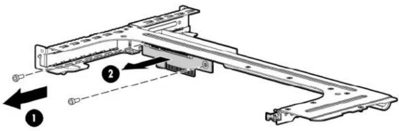
- Install the optional PCI-X riser board.

- Install a PCI-X expansion board ("Expansion board option" on page 38).

IMPORTANT: The server does not power up if the PCI riser board assembly is not seated properly.
- Install the PCI riser board assembly (on page 18).
- Connect all internal cables for expansion boards.
- Install the access panel.
- Install the server into the rack.
Storage controller option

IMPORTANT: For additional installation and configuration information, refer to the documentation that ships with the option.
To install the component:
- Power down the server (on page 16).
- Remove the server from the rack (on page 16).
- Remove the access panel (on page 17).
- Remove the air baffle (on page 17).
- Remove the PCI riser board assembly (on page 17).
-
Remove the hard drive cables.
-
Install the storage controller ("Expansion board option" on page 38).

IMPORTANT: The server does not power up if the PCI riser board assembly is not seated properly.
- Install the PCI riser board assembly (on page 18).
- Connect the mini-SAS to mini-SAS cable, provided in the mini-SAS to mini-SAS cable option kit, to the hard drive backplane and to the storage controller.
For more information, see "Optional SAS controller cabling (on page 50)."
- Install the access panel.
- Install the server into the rack.
Flash-backed write cache capacitor pack option
To install the component:

CAUTION: Do not use this controller with cache modules designed for other controller models, because the controller can malfunction and you can lose data. Also, do not transfer this cache module to a different controller module, because you can lose data.
- Back up all data.
- Close all applications.
- Power down the server (on page 16).

CAUTION: In systems that use external data storage, be sure that the server is the first unit to be powered down and the last to be powered back up. Taking this precaution ensures that the system does not erroneously mark the drives as failed when the server is powered up.
- Remove the server from the rack (on page 16).
- Remove the access panel (on page 17).
- Connect the capacitor pack cable to the connector on the top of the cache module.
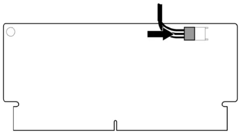
- Install the cache module.

- Install the storage controller, if not installed ("Storage controller option" on page 40).
- Install the capacitor pack.

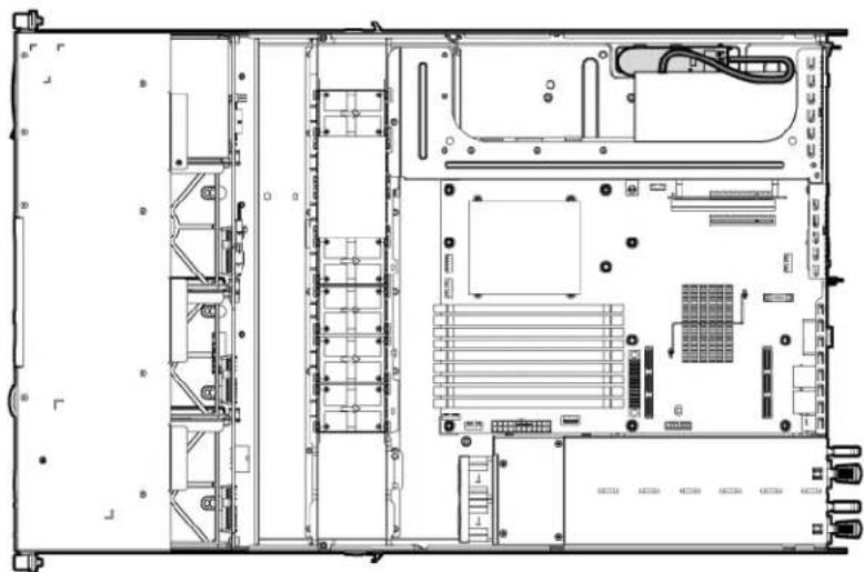
- Route the cable. ("BBWC battery pack or FBWC capacitor pack cabling to an optional controller" on page 51)
- Install the access panel.
- Install the server into the rack.
- Power up the server (on page 16).
Battery-backed write cache battery pack option

CAUTION: To prevent a server malfunction or damage to the equipment, do not add or remove the battery pack while an array capacity expansion, RAID level migration, or stripe size migration is in progress.
△
CAUTION: After the server is powered down, wait 15 seconds and then check the amber LED before unplugging the cable from the cache module. If the amber LED blinks after 15 seconds, do not remove the cable from the cache module. The cache module is backing up data, and data is lost if the cable is detached.
#
IMPORTANT: The battery pack might have a low charge when installed. In this case, a POST error message is displayed when the server is powered up, indicating that the battery pack is temporarily disabled. No action is necessary on your part. The internal circuitry automatically recharges the batteries and enables the battery pack. This process might take up to four hours. During this time, the cache module functions properly, but without the performance advantage of the battery pack.
NOTE: The data protection and the time limit also apply if a power outage occurs. When power is restored to the system, an initialization process writes the preserved data to the hard drives.
To install the component:
- Power down the server (on page 16).
- Remove the server from the rack (on page 16).
- Remove the access panel (on page 17).
- Install the storage controller, if not installed ("Storage controller option" on page 40).
- Install the cache module on the controller.

- Connect the cable to the cache module.

- Install the battery pack.

-
Route the cable ("BBWC battery pack or FBWC capacitor pack cabling to an optional controller" on page 51).
-
Install the access panel.
-
Install the server into the rack.
HP Trusted Platform Module option
Use these instructions to install and enable a TPM on a supported server. This procedure includes three sections:
- Installing the Trusted Platform Module board.
- Retaining the recovery key/password (on page 46).
- Enabling the Trusted Platform Module (on page 47).
Enabling the TPM requires accessing the ROM-Based Setup Utility (RBSU) ("HP ROM-Based Setup Utility" on page 53). For more information about RBSU, see the HP website (http://www.hp.com/support/smartstart/documentation).
TPM installation requires the use of drive encryption technology, such as the Microsoft® Windows® BitLocker™ Drive Encryption feature. For more information on BitLocker™, see the Microsoft website (http://www.microsoft.com).

CAUTION: Always observe the guidelines in this document. Failure to follow these guidelines can cause hardware damage or halt data access.
When installing or replacing a TPM, observe the following guidelines:
- Do not remove an installed TPM. Once installed, the TPM becomes a permanent part of the system board.
- When installing or replacing hardware, HP service providers cannot enable the TPM or the encryption technology. For security reasons, only the customer can enable these features.
- When returning a system board for service replacement, do not remove the TPM from the system board. When requested, HP Service provides a TPM with the spare system board.
- Any attempt to remove an installed TPM from the system board breaks or disfigures the TPM security rivet. Upon locating a broken or disfigured rivet on an installed TPM, administrators should consider the system compromised and take appropriate measures to ensure the integrity of the system data.
- When using BitLocker™, always retain the recovery key/password. The recovery key/password is required to enter Recovery Mode after BitLocker™ detects a possible compromise of system integrity.
- HP is not liable for blocked data access caused by improper TPM use. For operating instructions, see the encryption technology feature documentation provided by the operating system.
Installing the Trusted Platform Module board

WARNING: To reduce the risk of personal injury, electric shock, or damage to the equipment, remove the power cord to remove power from the server. The front panel Power On/Standby button does not completely shut off system power. Portions of the power supply and some internal circuitry remain active until AC power is removed.

WARNING: To reduce the risk of personal injury from hot surfaces, allow the drives and the internal system components to cool before touching them.
- Power down the server (on page 16).
- Remove the server from the rack (on page 16).
- Place the server on a flat, level work surface.
- Remove the access panel (on page 17).

CAUTION: Any attempt to remove an installed TPM from the system board breaks or disfigures the TPM security rivet. Upon locating a broken or disfigured rivet on an installed TPM, administrators should consider the system compromised and take appropriate measures to ensure the integrity of the system data.
- Install the TPM board. Press down on the connector to seat the board.

- Install the TPM security rivet by pressing the rivet firmly into the system board.

-
Install the access panel.
-
Install the server into the rack.
-
Power up the server (on page 16).
Retaining the recovery key/password
The recovery key/password is generated during BitLocker™ setup, and can be saved and printed after BitLocker™ is enabled. When using BitLocker™, always retain the recovery key/password. The recovery key/password is required to enter Recovery Mode after BitLocker™ detects a possible compromise of system integrity.
To help ensure maximum security, observe the following guidelines when retaining the recovery key/password:
• Always store the recovery key/password in multiple locations.
• Always store copies of the recovery key/password away from the server.
- Do not save the recovery key/password on the encrypted hard drive.
Enabling the Trusted Platform Module
- When prompted during the start-up sequence, access RBSU by pressing the F9 key.
- From the Main Menu, select Server Security.
- From the Server Security Menu, select Trusted Platform Module.
- From the Trusted Platform Module Menu, select TPM Functionality.
- Select Enable, and then press the Enter key to modify the TPM Functionality setting.
- Press the Esc key to exit the current menu, or press the F10 key to exit RBSU.
- Reboot the server.
- Enable the TPM in the OS. For OS-specific instructions, see the OS documentation.

CAUTION: When a TPM is installed and enabled on the server, data access is locked if you fail to follow the proper procedures for updating the system or option firmware, replacing the system board, replacing a hard drive, or modifying OS application TPM settings.
For more information on firmware updates and hardware procedures, see the HP Trusted Platform Module Best Practices White Paper on the HP website (http://www.hp.com/support).
For more information on adjusting TPM usage in BitLocker™, see the Microsoft website (http://technet.microsoft.com/en-us/windowsvista/aa905065.aspx).
Cabling
Cabling overview
This section provides guidelines that help you make informed decisions about cabling the server and hardware options to optimize performance.
Non-redundant power supply cabling

CAUTION: When routing cables, always be sure that the cables are not in a position where they can be pinched or air flow can be blocked.

IMPORTANT: Route the cables without blocking the airflow or other installed components. Use the cable clips installed in the chassis to manage cable routing.

Optional non-redundant high-efficiency power supply cabling

CAUTION: When routing cables, always be sure that the cables are not in a position where they can be pinched or air flow can be blocked.

IMPORTANT: Route the cables without blocking the airflow or other installed components. Use the cable clips installed in the chassis to manage cable routing.

Optional redundant power supply cabling

CAUTION: When routing cables, always be sure that the cables are not in a position where they can be pinched or air flow can be blocked.

IMPORTANT: Route the cables without blocking the airflow or other installed components. Use the cable clips installed in the chassis to manage cable routing.

Optional Common Slot Power Supply cabling

CAUTION: When routing cables, always be sure that the cables are not in a position where they can be pinched or air flow can be blocked.

IMPORTANT: Route the cables without blocking the airflow or other installed components. Use the cable clips installed in the chassis to manage cable routing.

SATA cabling

CAUTION: When routing cables, always be sure that the cables are not in a position where they can be pinched or air flow can be blocked.

IMPORTANT: Route the cables without blocking the airflow or other installed components. Use the cable clips installed in the chassis to manage cable routing.
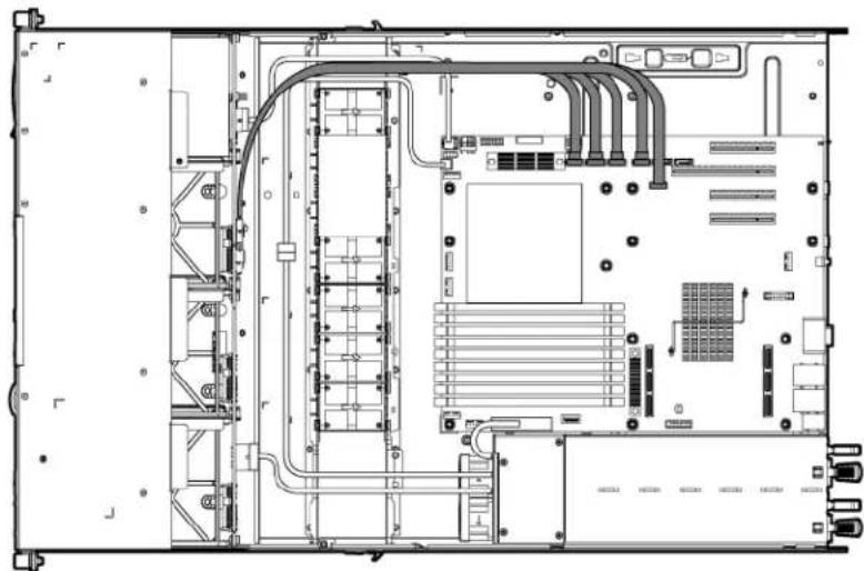
Optional SAS controller cabling

CAUTION: When routing cables, always be sure that the cables are not in a position where they can be pinched or air flow can be blocked.

BBWC battery pack or FBWC capacitor pack
cabling to an optional controller
Configuration and utilities
Configuration tools
SmartStart software
SmartStart is a collection of software that optimizes single-server setup, providing a simple and consistent way to deploy server configuration. SmartStart has been tested on many ProLiant server products, resulting in proven, reliable configurations.
SmartStart assists the deployment process by performing a wide range of configuration activities, including:
• Preparing the system for installing "off-the-shelf" versions of leading operating system software
• Installing optimized server drivers, management agents, and utilities automatically with every assisted installation
- Testing server hardware using the Insight Diagnostics Utility ("HP Insight Diagnostics" on page 59)
• Installing software drivers directly from the CD. With systems that have Internet connection, the SmartStart Autorun Menu provides access to a complete list of Proliant system software.
• Enabling access to the Array Configuration Utility (on page 55) and Erase Utility (on page 57)
SmartStart is included in the HP Insight Foundation suite for ProLiant. For more information about SmartStart software, see the HP Insight Foundation suite for ProLiant or the HP website (http://www.hp.com/go/foundation).
SmartStart Scripting Toolkit
The SmartStart Scripting Toolkit is a server deployment product that delivers an unattended automated installation for high-volume server deployments. The SmartStart Scripting Toolkit is designed to support ProLiant BL, ML, DL, and 100 series servers. The toolkit includes a modular set of utilities and important documentation that describes how to apply these new tools to build an automated server deployment process.
Using SmartStart technology, the Scripting Toolkit provides a flexible way to create standard server configuration scripts. These scripts are used to automate many of the manual steps in the server configuration process. This automated server configuration process cuts time from each deployment, making it possible to scale server deployments to high volumes in a rapid manner.
For more information, and to download the SmartStart Scripting Toolkit, see the HP website (http://www.hp.com/servers/sstoolkit).
Configuration Replication Utility
CONREP is shipped in the SmartStart Scripting Toolkit and is a program that works with RBSU to replicate hardware configuration on ProLiant servers. This utility is run during State 0, Run Hardware Configuration Utility, when doing a scripted server deployment. CONREP reads the state of the system environment
variables to determine the configuration and then writes the results to an editable script file. This file can then be deployed across multiple servers with similar hardware and software components. For more information, refer to the SmartStart Scripting Toolkit User Guide on the HP website (http://h18004.www1.hp.com/products/servers/management/toolkit/documentation.html).
HP ROM-Based Setup Utility
RBSU is a configuration utility embedded in ProLiant servers that performs a wide range of configuration activities that can include the following:
• Enabling and disabling system features
• Displaying system information
• Selecting the primary boot controller
- Configuring memory options
• Language selection
- Configuring system devices and installed options
For more information on RBSU, see the HP ROM-Based Setup Utility User Guide on the Documentation CD or the HP website (http://www.hp.com/support/smartstart/documentation).
Using RBSU
To use RBSU, use the following keys:
• To access RBSU, press the F9 key during power-up when prompted.
• To navigate the menu system, use the arrow keys.
• To make selections, press the Enter key.
• To access Help for a highlighted configuration option, press the F1 key.

IMPORTANT: RBSU automatically saves settings when you press the Enter key. The utility does not prompt you for confirmation of settings before you exit the utility. To change a selected setting, you must select a different setting and press the Enter key.
Default configuration settings are applied to the server at one of the following times:
• Upon the first system power-up
• After defaults have been restored
Default configuration settings are sufficient for proper typical server operation, but configuration settings can be modified using RBSU. The system will prompt you for access to RBSU with each power-up.
Auto-configuration process
The auto-configuration process automatically runs when you boot the server for the first time. During the power-up sequence, the system ROM automatically configures the entire system without needing any intervention. During this process, the ORCA utility, in most cases, automatically configures the array to a default setting based on the number of drives connected to the server.
NOTE: The server may not support all the following examples.
NOTE: If the boot drive is not empty or has been written to in the past, ORCA does not automatically configure the array. You must run ORCA to configure the array settings.
| Drives installed | Drives used | RAID level |
| 1 1 RAID 0 | ||
| 2 2 RAID 1 | ||
| 3, 4, 5, or 6 | 3, 4, 5, or 6 | RAID 5 |
| More than 6 0 None |
To change any ORCA default settings and override the auto-configuration process, press the F8 key when prompted.
By default, the auto-configuration process configures the system for the English language. To change any default settings in the auto-configuration process (such as the settings for language, operating system, and primary boot controller), execute RBSU by pressing the F9 key when prompted. After the settings are selected, exit RBSU and allow the server to reboot automatically.
For more information on RBSU, see the HP ROM-Based Setup Utility User Guide on the Documentation CD or the HP website (http://www.hp.com/support/smartstart/documentation).
Boot options
Near the end of the boot process, the boot options screen is displayed. This screen is visible for several seconds before the system attempts to boot from a supported boot device. During this time, you can do the following:
• Access RBSU by pressing the F9 key.
- Access the System Maintenance Menu (which enables you to launch ROM-based Diagnostics or Inspect) by pressing the F10 key.
• Force a PXE Network boot by pressing the F12 key.
BIOS Serial Console
BIOS Serial Console allows you to configure the serial port to view POST error messages and run RBSU remotely through a serial connection to the server COM port. The server that you are remotely configuring does not require a keyboard and mouse.
For more information about BIOS Serial Console, see the BIOS Serial Console User Guide on the Documentation CD or the HP website (http://www.hp.com/support/smartstart/documentation).
Configuring mirrored memory
To configure mirrored memory:
- Install the required DIMMs ("Installing a DIMM" on page 31).
- Access RBSU by pressing the F9 key during power-up when the prompt is displayed.
- Select System Options.
- Select Advanced Memory Protection.
- Select Mirrored Memory with Advanced ECC Support.
-
Press the Enter key.
-
Press the Esc key to exit the current menu or press the F10 key to exit RBSU.
For more information on mirrored memory, see the white paper on the HP website (http://h18000.www1.hp.com/products/servers/technology/memoryprotection.html).
Configuring lockstep memory
To configure Lockstep memory:
- Install the required DIMMs ("Installing a DIMM" on page 31).
- Access RBSU by pressing the F9 key during power-up when the prompt is displayed.
- Select System Options.
- Select Advanced Memory Protection.
- Select Lockstep with Advanced ECC Support.
- Press the Enter key.
- Press the Esc key to exit the current menu, or press the F10 key to exit RBSU.
For more information on Lockstep memory, see the white paper on the HP website (http://h18000.www1.hp.com/products/servers/technology/memoryprotection.html).
Array Configuration Utility
ACU is a browser-based utility with the following features:
- Runs as a local application or remote service
• Supports online array capacity expansion, logical drive extension, assignment of online spares, and RAID or stripe size migration
• Suggests the optimum configuration for an unconfigured system - Provides different operating modes, enabling faster configuration or greater control over the configuration options
• Remains available any time that the server is on
• Displays on-screen tips for individual steps of a configuration procedure
For optimum performance, the minimum display settings are 800 × 600 resolution and 256 colors. Servers running Microsoft® operating systems require Internet Explorer 5.5 (with Service Pack 1) or later. For Linux servers, refer to the README.TXT file for additional browser and support information.
For more information, refer to the Configuring Arrays on HP Smart Array Controllers Reference Guide on the Documentation CD or the HP website (http://www.hp.com).
Option ROM Configuration for Arrays
Before installing an operating system, you can use the ORCA utility to create the first logical drive, assign RAID levels, and establish online spare configurations.
The utility also provides support for the following functions:
• Reconfiguring one or more logical drives
• Viewing the current logical drive configuration
• Deleting a logical drive configuration
- Setting the controller to be the boot controller
If you do not use the utility, ORCA will default to the standard configuration.
For more information regarding array controller configuration, refer to the controller user guide.
For more information regarding the default configurations that ORCA uses, refer to the HP ROM-Based Setup Utility User Guide on the Documentation CD.
HP ProLiant Essentials Rapid Deployment Pack
The RDP software is the preferred method for rapid, high-volume server deployments. The RDP software integrates two powerful products: Altiris Deployment Solution and the HP ProLiant Integration Module.
The intuitive graphical user interface of the Altiris Deployment Solution console provides simplified point-and-click and drag-and-drop operations that enable you to deploy target servers, including server blades, remotely. It enables you to perform imaging or scripting functions and maintain software images.
For more information about the RDP, refer to the HP ProLiant Essentials Rapid Deployment Pack CD or refer to the HP website (http://www.hp.com/servers/rdp).
Re-entering the server serial number and product ID
After you replace the system board, you must re-enter the server serial number and the product ID.
- During the server startup sequence, press the F9 key to access RBSU.
- Select the System Options menu.
- Select Serial Number. The following warning is displayed:
WARNING! WARNING! WARNING! The serial number is loaded into the system during the manufacturing process and should NOT be modified. This option should only be used by qualified service personnel. This value should always match the serial number sticker located on the chassis. - Press the Enter key to clear the warning.
- Enter the serial number and press the Enter key.
- Select Product ID.
- Enter the product ID and press the Enter key.
- Press the Esc key to close the menu.
- Press the Esc key to exit RBSU.
- Press the F10 key to confirm exiting RBSU. The server will automatically reboot.
Management tools
Automatic Server Recovery
ASR is a feature that causes the system to restart when a catastrophic operating system error occurs, such as a blue screen, ABEND, or panic. A system fail-safe timer, the ASR timer, starts when the System Management driver, also known as the Health Driver, is loaded. When the operating system is functioning properly, the system periodically resets the timer. However, when the operating system fails, the timer expires and restarts the server.
ASR increases server availability by restarting the server within a specified time after a system hang or shutdown. At the same time, the HP SIM console notifies you by sending a message to a designated pager number that ASR has restarted the system. You can disable ASR from the HP SIM console or through RBSU.
ROMPaq utility
The ROMPaq utility enables you to upgrade the system firmware (BIOS). To upgrade the firmware, insert a ROMPaq diskette into the diskette drive or ROMPaq USB Key into an available USB port and boot the system. Online versions of the ROMPaq utility are also available for updating the system firmware.
The ROMPaq utility checks the system and provides a choice (if more than one exists) of available firmware revisions.
For more information about the ROMPaq utility, see the HP website (http://www.hp.com/go/support).
Integrated Lights-Out 2 technology
The iLO 2 subsystem is a standard component of selected ProLiant servers that provides server health and remote server manageability. The iLO 2 subsystem includes an intelligent microprocessor, secure memory, and a dedicated network interface. This design makes iLO 2 independent of the host server and its operating system. The iLO 2 subsystem provides remote access to any authorized network client, sends alerts, and provides other server management functions.
Using iLO 2, you can:
- Remotely power up, power down, or reboot the host server.
- Send alerts from iLO 2 regardless of the state of the host server.
- Access advanced troubleshooting features through the iLO 2 interface.
- Diagnose iLO 2 using HP SIM through a web browser and SNMP alerting.
For more information about iLO 2 features (which may require an iLO Advanced Pack or iLO Advanced for BladeSystem license), see the iLO 2 documentation on the Documentation CD or on the HP website (http://www.hp.com/servers/lights-out).
Erase Utility

CAUTION: Perform a backup before running the System Erase Utility. The utility sets the system to its original factory state, deletes the current hardware configuration information, including array setup and disk partitioning, and erases all connected hard drives completely. Refer to the instructions for using this utility.
Run the Erase Utility if you must erase the system for the following reasons:
- You want to install a new operating system on a server with an existing operating system.
- You encounter an error when completing the steps of a factory-installed operating system installation.
To access the Erase Utility, use the System Erase button on the home screen of the SmartStart CD ("SmartStart software" on page 52).
StorageWorks library and tape tools
HP StorageWorks L&TT provides functionality for firmware downloads, verification of device operation, maintenance procedures, failure analysis, corrective service actions, and some utility functions. It also provides seamless integration with HP hardware support by generating and emailing support tickets that deliver a snapshot of the storage system.
For more information, and to download the utility, refer to the StorageWorks L&TT website (http://h18006.www1.hp.com/products/storageworks/ltt).
HP Systems Insight Manager
HP SIM is a web-based application that allows system administrators to accomplish normal administrative tasks from any remote location, using a web browser. HP SIM provides device management capabilities that consolidate and integrate management data from HP and third-party devices.

IMPORTANT: You must install and use HP SIM to benefit from the Pre-Failure Warranty for processors, SAS and SATA hard drives, and memory modules.
For additional information, refer to the Management CD in the HP ProLiant Essentials Foundation Pack or the HP SIM website (http://www.hp.com/go/hpsim).
Management Agents
Management Agents provide the information to enable fault, performance, and configuration management. The agents allow easy manageability of the server through HP SIM software, and third-party SNMP management platforms. Management Agents are installed with every SmartStart assisted installation or can be installed through the HP PSP. The Systems Management homepage provides status and direct access to in-depth subsystem information by accessing data reported through the Management Agents. For additional information, refer to the Management CD in the HP ProLiant Essentials Foundation Pack or the HP website (http://www.hp.com/servers/manage).
Redundant ROM support
The server enables you to upgrade or configure the ROM safely with redundant ROM support. The server has a 8-MB ROM that acts as two, separate 4-MB ROMs. In the standard implementation, one side of the ROM contains the current ROM program version, while the other side of the ROM contains a backup version.
NOTE: The server ships with the same version programmed on each side of the ROM.
Safety and security benefits
When you flash the system ROM, ROMPaq writes over the backup ROM and saves the current ROM as a backup, enabling you to switch easily to the alternate ROM version if the new ROM becomes corrupted for any reason. This feature protects the existing ROM version, even if you experience a power failure while flashing the ROM.
USB support
HP provides both standard USB support and legacy USB support. Standard support is provided by the OS through the appropriate USB device drivers. Before the OS loads, HP provides support for USB devices through legacy USB support, which is enabled by default in the system ROM.
Legacy USB support provides USB functionality in environments where USB support is not available normally. Specifically, HP provides legacy USB functionality for the following:
POST
RBSU
• Diagnostics
• DOS
- Operating environments which do not provide native USB support
Internal USB functionality
An internal USB connector is available for use with USB drive keys only. This solution provides for use of a permanent boot drive from a USB drive key installed in the internal connector, avoiding issues of clearance on the front of the rack and physical access to secure data.
For additional security, you can disable the external USB connectors through RBSU. Disabling the rear USB connectors in RBSU disables both rear USB ports.
Internal SD support
An internal SD connector is available for use with embedded Hypervisors. This solution provides for use of a permanently installed SD card in the internal connector, decreasing the possibility of tampering or loss.
Diagnostic tools
HP Insight Diagnostics
HP Insight Diagnostics is a proactive server management tool, available in both offline and online versions, that provides diagnostics and troubleshooting capabilities to assist IT administrators who verify server installations, troubleshoot problems, and perform repair validation.
HP Insight Diagnostics Offline Edition performs various in-depth system and component testing while the OS is not running. To run this utility, launch the SmartStart CD.
HP Insight Diagnostics Online Edition is a web-based application that captures system configuration and other related data needed for effective server management. Available in Microsoft® Windows® and Linux versions, the utility helps to ensure proper system operation.
For more information or to download the utility, refer to the HP website (http://www.hp.com/servers/diags).
HP Insight Diagnostics survey functionality
HP Insight Diagnostics (on page 59) provides survey functionality that gathers critical hardware and software information on ProLiant servers.
This functionality supports operating systems that may not be supported by the server. For operating systems supported by the server, see the HP website (http://www.hp.com/go/supportos).
If a significant change occurs between data-gathering intervals, the survey function marks the previous information and overwrites the survey data files to reflect the latest changes in the configuration.
Survey functionality is installed with every SmartStart-assisted HP Insight Diagnostics installation, or it can be installed through the HP PSP ("ProLiant Support Packs" on page 62).
NOTE: The current version of SmartStart provides the memory spare part numbers for the server. To download the latest version, see the HP website (http://www.hp.com/support).
Integrated Management Log
The IML records hundreds of events and stores them in an easy-to-view form. The IML timestamps each event with 1-minute granularity.
You can view recorded events in the IML in several ways, including the following:
• From within Survey Utility
• From within operating system-specific IML viewers
- For NetWare: IML Viewer
- For Windows®: IML Viewer
- For Linux: IML Viewer Application
• From within the iLO 2 user interface
• From within HP Insight Diagnostics (on page 59)
• From within HP SIM ("HP Systems Insight Manager" on page 58)
For more information, see the Management CD in the HP Insight Foundation suite for ProLiant.
Array Diagnostic Utility
The HP Array Diagnostics Utility is a web-based application that creates a report of all HP storage controllers and disk drives. This report provides vital information to assist in identifying faults or conditions that may require attention. ADU can be accessed from the SmartStart CD ("SmartStart software" on page 52) or downloaded from the HP website (http://www.hp.com).
HP Insight Remote Support software
HP Insight Remote Support software delivers secure remote support for your HP Servers and Storage, 24 X 7, so you can spend less time solving problems and more time focused on your business. You can have your systems remotely monitored for hardware failure using secure technology that has been proven at thousands of companies around the world. In many cases, you can avoid problems before they occur. There are two HP Insight Remote Support solutions:
- For small and midsize environments: HP Insight Remote Support Standard provides basic remote monitoring, notification/advisories and service dispatch. It is optimized for environments with 1 to 50 servers and can be installed on a shared HP ProLiant Windows application server. The software supports HP EVA storage devices, HP ProLiant, BladeSystems, HP Integrity and HP 9000 servers running Microsoft Windows, Red Hat Enterprise Linux, Novell SUSE and Novell Netware. Download from the HP website (http://h20392.www2.hp.com/portal/swdepot/displayProductInfo.do?productNumber=RSSWMBASE).
- For midsize and large environments: HP Insight Remote Support Pack (formerly Service Essentials Remote Support Pack) is targeted for larger environments and is integrated with HP Systems Insight Manager (SIM). It provides comprehensive remote monitoring, notification/advisories, dispatch and proactive service support for nearly all HP servers, storage, network and SAN environments, plus selected Dell and IBM Windows servers that have a support obligation with HP. It also enables HP to deliver higher levels of proactive support in line with HP Mission Critical Services support agreements. Download from the HP website (http://h20392.www2.hp.com/portal/swdepot/displayProductInfo.do?productNumber=ISDVD).
Both HP Insight Remote Support solutions are available at no additional cost to customers with a valid warranty on HP technology, an HP Care Pack Service or HP contractual support agreement.
For more information, see the HP website (http://www.hp.com/go/insightremotesupport).
HP Insight Server Migration software for ProLiant
The HP Insight Server Migration software for ProLiant (SMP) enables administrators to upgrade or replace an existing server through server migration. SMP provides an automated, accurate, and affordable method of migrating existing servers and their content to the latest server technologies.
SMP automates the migration of the operating system, applications, and data from one server to another without errors, eliminating the need for manual redeployment of these elements on the new server. During the migration process, the software automatically loads new drivers, required for boot, on the destination server. The wizard-based user interface simplifies the migration process and requires little experience or training.
For more information about the SMP, see the HP website (http://www.hp.com/go/migrate).
Keeping the system current
Drivers
The server includes new hardware that may not have driver support on all operating system installation media.
If you are installing a SmartStart-supported operating system, use the SmartStart software (on page 52) and its Assisted Path feature to install the operating system and latest driver support.
NOTE: If you are installing drivers from the SmartStart CD or the Software Maintenance CD, refer to the SmartStart website (http://www.hp.com/servers/smartstart) to be sure that you are using the latest version of SmartStart. For more information, refer to the documentation provided with the SmartStart CD.
If you do not use the SmartStart CD to install an operating system, drivers for some of the new hardware are required. These drivers, as well as other option drivers, ROM images, and value-add software can be downloaded from the HP website (http://www.hp.com/support).

IMPORTANT: Always perform a backup before installing or updating device drivers.
ProLiant Support Packs
PSPs represent operating system-specific bundles of ProLiant optimized drivers, utilities, and management agents. Refer to the PSP website
(http://h18000.www1.hp.com/products/servers/management/psp.html).
Operating system version support
Refer to the operating system support matrix (http://www.hp.com/go/supportos).
System Online ROM flash component utility
The Online ROM Flash Component Utility enables system administrators to efficiently upgrade system or controller ROM images across a wide range of servers and array controllers. This tool has the following features:
• Works offline and online
Supports Windows Server® 2003, Windows Server® 2008, Novell Netware, and Linux operating systems

IMPORTANT: This utility supports operating systems that may not be supported by the server. For operating systems supported by the server, see the HP website (http://www.hp.com/support).
• Integrates with other software maintenance, deployment, and operating system tools
- Automatically checks for hardware, firmware, and operating system dependencies, and installs only the correct ROM upgrades required by each target server
To download the tool and for more information, see the HP website (http://www.hp.com/support).
Change control and proactive notification
HP offers Change Control and Proactive Notification to notify customers 30 to 60 days in advance of upcoming hardware and software changes on HP commercial products.
For more information, refer to the HP website (http://www.hp.com/go/pcn).
Care Pack
HP Care Pack Services offer upgraded service levels to extend and expand standard product warranty with easy-to-buy, easy-to-use support packages that help you make the most of your server investments. Refer to the Care Pack website (http://www.hp.com/hps/carepack/servers/cp_proliant.html).
Troubleshooting
Troubleshooting resources
The HP ProLiant Servers Troubleshooting Guide provides procedures for resolving common problems and comprehensive courses of action for fault isolation and identification, error message interpretation, issue resolution, and software maintenance on ProLiant servers and server blades. This guide includes problem-specific flowcharts to help you navigate complex troubleshooting processes. To view the guide, select a language:
• English (http://www.hp.com/support/ProLiant_TSG_en)
French (http://www.hp.com/support/ProLiant_TSG_fr)
• Italian (http://www.hp.com/support/ProLiant_TSG_it)
• Spanish (http://www.hp.com/support/ProLiant TSG sp)
• German (http://www.hp.com/support/ProLiant_TSG_gr)
• Dutch (http://www.hp.com/support/ProLiant_TSG_nl)
• Japanese (http://www.hp.com/support/ProLiant_TSG_jp)
Pre-diagnostic steps

WARNING: To avoid potential problems, ALWAYS read the warnings and cautionary information in the server documentation before removing, replacing, reseating, or modifying system components.

IMPORTANT: This guide provides information for multiple servers. Some information may not apply to the server you are troubleshooting. Refer to the server documentation for information on procedures, hardware options, software tools, and operating systems supported by the server.
- Review the important safety information (on page 63).
- Gather symptom information (on page 65).
- Prepare the server for diagnosis (on page 66).
- Use the Start diagnosis flowchart (on page 67) to begin the diagnostic process.
Important safety information
Familiarize yourself with the safety information in the following sections before troubleshooting the server.

Important safety information
Before servicing this product, read the Important Safety Information document provided with the server.
Symbols on equipment
The following symbols may be placed on equipment to indicate the presence of potentially hazardous conditions.

This symbol indicates the presence of hazardous energy circuits or electric shock hazards. Refer all servicing to qualified personnel.
WARNING: To reduce the risk of injury from electric shock hazards, do not open this enclosure. Refer all maintenance, upgrades, and servicing to qualified personnel.

This symbol indicates the presence of electric shock hazards. The area contains no user or field serviceable parts. Do not open for any reason.
WARNING: To reduce the risk of injury from electric shock hazards, do not open this enclosure.

This symbol on an RJ-45 receptacle indicates a network interface connection.
WARNING: To reduce the risk of electric shock, fire, or damage to the equipment, do not plug telephone or telecommunications connectors into this receptacle.

This symbol indicates the presence of a hot surface or hot component. If this surface is contacted, the potential for injury exists.
WARNING: To reduce the risk of injury from a hot component, allow the surface to cool before touching.

This symbol indicates that the component exceeds the recommended weight for one individual to handle safely.
49-109 kg 100-240 lb
WARNING: To reduce the risk of personal injury or damage to the equipment, observe local occupational health and safety requirements and guidelines for manual material handling.

These symbols, on power supplies or systems, indicate that the equipment is supplied by multiple sources of power.
WARNING: To reduce the risk of injury from electric shock, remove all power cords to completely disconnect power from the system.
Warnings and cautions

WARNING: Only authorized technicians trained by HP should attempt to repair this equipment. All troubleshooting and repair procedures are detailed to allow only subassembly/module-level repair. Because of the complexity of the individual boards and subassemblies, no one should attempt to make repairs at the component level or to make modifications to any printed wiring board. Improper repairs can create a safety hazard.

WARNING: To reduce the risk of personal injury or damage to the equipment, be sure that:
• The leveling feet are extended to the floor.
- The full weight of the rack rests on the leveling feet.
- The stabilizing feet are attached to the rack if it is a single-rack installation.
- The racks are coupled together in multiple-rack installations.
- Only one component is extended at a time. A rack may become unstable if more than one component is extended for any reason.
!
WARNING: To reduce the risk of electric shock or damage to the equipment:
- Do not disable the power cord grounding plug. The grounding plug is an important safety feature.
- Plug the power cord into a grounded (earthed) electrical outlet that is easily accessible at all times.
- Unplug the power cord from the power supply to disconnect power to the equipment.
- Do not route the power cord where it can be walked on or pinched by items placed against it. Pay particular attention to the plug, electrical outlet, and the point where the cord extends from the server.

49-109 kg 100-240 lb
WARNING: To reduce the risk of personal injury or damage to the equipment:
- Observe local occupation health and safety requirements and guidelines for manual handling.
- Obtain adequate assistance to lift and stabilize the chassis during installation or removal.
• The server is unstable when not fastened to the rails. - When mounting the server in a rack, remove the power supplies and any other removable module to reduce the overall weight of the product.
△
CAUTION: To properly ventilate the system, you must provide at least 7.6 cm (3.0 in) of clearance at the front and back of the server.
△
CAUTION: The server is designed to be electrically grounded (earthed). To ensure proper operation, plug the AC power cord into a properly grounded AC outlet only.
Symptom information
Before troubleshooting a server problem, collect the following information:
• What events preceded the failure? After which steps does the problem occur?
• What has been changed since the time the server was working?
- Did you recently add or remove hardware or software? If so, did you remember to change the appropriate settings in the server setup utility, if necessary?
• How long has the server exhibited problem symptoms?
• If the problem occurs randomly, what is the duration or frequency?
To answer these questions, the following information may be useful:
- Run HP Insight Diagnostics (on page 59) and use the survey page to view the current configuration or to compare it to previous configurations.
• Refer to your hardware and software records for information.
• Refer to server LEDs and their statuses.
Prepare the server for diagnosis
- Be sure the server is in the proper operating environment with adequate power, air conditioning, and humidity control. For required environmental conditions, see the server documentation.
- Record any error messages displayed by the system.
- Remove all diskettes, CD-ROMs, DVD-ROMs, and USB drive keys.
- Power down the server and peripheral devices if you will be diagnosing the server offline. If possible, always perform an orderly shutdown:
a. Exit any applications.
b. Exit the operating system.
c. Power down the server (on page 16).
- Disconnect any peripheral devices not required for testing (any devices not necessary to power up the server). Do not disconnect the printer if you want to use it to print error messages.
- Collect all tools and utilities, such as a Torx screwdriver, loopback adapters, ESD wrist strap, and software utilities, necessary to troubleshoot the problem.
- You must have the appropriate Health Drivers and Management Agents installed on the server. To verify the server configuration, connect to the System Management homepage and select Version Control Agent. The VCA gives you a list of names and versions of all installed HP drivers, Management Agents, and utilities, and whether they are up-to-date.
- HP recommends you have access to the server documentation for server-specific information.
- HP recommends you have access to the SmartStart CD for value-added software and drivers required during the troubleshooting process. Download the current version of SmartStart from the HP website (http://www.hp.com/servers/smartstart).
Loose connections
Action:
- Be sure all power cords are securely connected.
- Be sure all cables are properly aligned and securely connected for all external and internal components.
- Remove and check all data and power cables for damage. Be sure no cables have bent pins or damaged connectors.
- If a fixed cable tray is available for the server, be sure the cords and cables connected to the server are routed correctly through the tray.
- Be sure each device is properly seated. Avoid bending or flexing circuit boards when reseating components.
• If a device has latches, be sure they are completely closed and locked. - Check any interlock or interconnect LEDs that may indicate a component is not connected properly.
- If problems continue to occur, remove and reinstall each device, checking the connectors and sockets for bent pins or other damage.
Service notifications
To view the latest service notifications, refer to the HP website (http://www.hp.com/go/bizsupport).
Select the appropriate server model, and then click the Troubleshoot a Problem link on the product page.
Troubleshooting flowcharts
To effectively troubleshoot a problem, HP recommends that you start with the first flowchart in this section, "Start diagnosis flowchart (on page 67)," and follow the appropriate diagnostic path. If the other flowcharts do not provide a troubleshooting solution, follow the diagnostic steps in "General diagnosis flowchart (on page 68)." The General diagnosis flowchart is a generic troubleshooting process to be used when the problem is not server-specific or is not easily categorized into the other flowcharts.
The available flowcharts include:
• Start diagnosis flowchart (on page 67)
• General diagnosis flowchart (on page 68)
• Server power-on problems flowchart (on page 70)
• POST problems flowchart (on page 73)
• OS boot problems flowchart (on page 74)
• Server fault indications flowchart (on page 76)
Start diagnosis flowchart
Use the following flowchart to start the diagnostic process.
| Item Refer to | |
| 1 | "General diagnosis flowchart (on page 68)" |
| 2 | "Power-on problems flowchart ("Server power-on problems flowchart" on page 70)" |
| 3 | "POST problems flowchart (on page 73)" |
| 4 | "OS boot problems flowchart (on page 74)" |
| 5 | "Server fault indications flowchart (on page 76)" |
![graph TD A["Start diagnosis"] --> B{Do you want to perform the General Diagnosis?} B -->|Yes| C["(1) Go to General diagnosis"] B -->|No| D{Does server power on?} D -->|No| E["(2) Go to Power-on problems"] D -->|Yes| F{Does server complete POST OK?} F -->|No| G["(3) Go to POST problems"] F -->|Yes| H…](/content/2026/07/1524168/images/fc0053bf35f7e021a0e87da7b70ff6939827e0a31f816e85c8c39b0040e654a3.jpg)
General diagnosis flowchart
The General diagnosis flowchart provides a generic approach to troubleshooting. If you are unsure of the problem, or if the other flowcharts do not fix the problem, use the following flowchart.
| Item Refer to | |
| 1 | "Symptom information (on page 65)" |
| 2 | "Loose connections (on page 66)" |
| 3 | "Service notifications (on page 67)" |
| 4 | The most recent version of a particular server or option firmware is available on the HP Support website (http://www.hp.com/support). |
| 5 | "General memory problems are occurring" in the HP ProLiant Servers Troubleshooting Guide located on the Documentation CD or on the HP website (http://www.hp.com/support) |
| 6 | Server maintenance and service guide, located on the Documentation CD or the HP website (http://www.hp.com/products/servers/platforms) |
| 7 | Server maintenance and service guide, located on the Documentation CD or the HP website (http://www.hp.com/products/servers/platforms)"Hardware problems" in the HP ProLiant Servers Troubleshooting Guide located on the Documentation CD or on the HP website (http://www.hp.com/support) |
| 8 | "Server information you need" in the HP ProLiant Servers Troubleshooting Guide located on the Documentation CD or on the HP website (http://www.hp.com/support)"Operating system information you need" in the HP ProLiant Servers Troubleshooting Guide located on the Documentation CD or on the HP website (http://www.hp.com/support) |
| 9 | "HP contact information (on page 92)" |
![graph TD A["Start General diagnosis"] --> B["(1) Record symptom information."] B --> C["Reboot server to see if condition still exists."] C --> D{Is this a newly installed server?} D -->|Yes| E["(2) Reseat any components that may have come loose during shipping and reboot the server."] E --> F{Does…](/content/2026/07/1524168/images/3d4fb41ab1a850bf8dd08db88a8f6763963298c0d44dc75cdd90c1a8437e7c4e.jpg)
Server power-on problems flowchart
Symptoms:
• The server does not power on.
• The system power LED is off or amber.
• The external health LED is red or amber.
• The internal health LED is red or amber.
NOTE: For the location of server LEDs and information on their statuses, refer to the server documentation.
Possible causes:
• Improperly seated or faulty power supply
- Loose or faulty power cord
• Power source problem
• Power on circuit problem
- Improperly seated component or interlock problem
• Faulty internal component
| Item Refer to | |
| 1 | "Component identification (on page 7)" |
| 2 | "HP Insight Diagnostics (on page 59)" or in the HP ProLiant Servers Troubleshooting Guide located on the Documentation CD or on the HP website (http://www.hp.com/support) |
| 3 | "Loose connections (on page 66)" |
| 4 | Server maintenance and service guide, located on the Documentation CD, or the HP website (http://www.hp.com/products/servers/platforms) |
| 5 | "Integrated Management Log (on page 60)" or in the HP ProLiant Servers Troubleshooting Guide located on the Documentation CD or on the HP website (http://www.hp.com/support) |
| 6 | "Power source problems" in the HP ProLiant Servers Troubleshooting Guide located on the Documentation CD or on the HP website (http://www.hp.com/support) |
| 7 | • "Power supply problems" in the HP ProLiant Servers Troubleshooting Guide located on the Documentation CD or on the HP website (http://www.hp.com/support)• Server maintenance and service guide, located on the Documentation CD, or the HP website (http://www.hp.com/products/servers/platforms) |
| 8 | "System open circuits and short circuits" in the HP ProLiant Servers Troubleshooting Guide located on the Documentation CD or on the HP website (http://www.hp.com/support) |
![graph TD A["Start Power-on problems"] --> B{(1) Is the internal health LED red or amber?} B -->|No| C{Amber or Green} B -->|Yes| D{(1) Are any component health LEDs on?} D -->|No| E["(2) Use maintenance tools to identify the problem."] D -->|Yes| F["(3) Reseat indicated component. Check for loose co…](/content/2026/07/1524168/images/f9b27ef49fb1cd1c5acdfd75f46eb19458e3d39e5bca8fe3ca6ee2a31839e1bc.jpg)
POST problems flowchart
Symptoms:
• Server does not complete POST
NOTE: The server has completed POST when the system attempts to access the boot device.
• Server completes POST with errors
Possible problems:
• Improperly seated or faulty internal component
- Faulty KVM device
- Faulty video device
| Item Refer to | |
| 1 | "POST error messages and beep codes (on page 78)" |
| 2 | "Video problems" in the HP ProLiant Servers Troubleshooting Guide located on the Documentation CD or on the HP website (http://www.hp.com/support) |
| 3 KVM or | iLO 2 documentation |
| 4 | "Loose connections (on page 66)" |
| 5 | "Symptom information (on page 65)" |
| 6 | Server maintenance and service guide, located on the Documentation CD or the HP website (http://www.hp.com/products/servers/platforms) |
| 7 | "Port 85 and iLO messages" in the HP ProLiant Servers Troubleshooting Guide located on the Documentation CD or on the HP website (http://www.hp.com/support) |
| 8 | "General memory problems are occurring" in the HP ProLiant Servers Troubleshooting Guide located on the Documentation CD or on the HP website (http://www.hp.com/support) |
| 9 | "Hardware problems" in the HP ProLiant Servers Troubleshooting Guide located on the Documentation CD or on the HP website (http://www.hp.com/support)Server maintenance and service guide, located on the Documentation CD or the HP website (http://www.hp.com/products/servers/platforms) |
| 10 | "Server information you need" in the HP ProLiant Servers Troubleshooting Guide located on the Documentation CD or on the HP website (http://www.hp.com/support)"Operating system information you need" in the HP ProLiant Servers Troubleshooting Guide located on the Documentation CD or on the HP website (http://www.hp.com/support) |
Item Refer to
![graph TD A["Start POST Problems"] --> B{Have video output?} B -->|No| C["(2) Verify video is cabled correctly."] B -->|Yes| D{POST errors messages displayed?} D -->|No| E{Are the fans on?} D -->|Yes| F["(1) Refer to "Post Error Messages.""] E -->|No| G{Are there any beep codes?} E -->|Yes|…](/content/2026/07/1524168/images/a681e1ae5587e59c1e3816dca2329c357af1714d7ae3e280b8baad87604ffb48.jpg)
OS boot problems flowchart
Symptoms:
• Server does not boot a previously installed operating system
• Server does not boot SmartStart
Possible causes:
• Corrupted operating system
• Hard drive subsystem problem
• Incorrect boot order setting in RBSU
| Item Refer to | |
| 1 | HP ROM-Based Setup Utility User Guide(http://www.hp.com/servers/smartstart) |
| 2 | "POST problems flowchart (on page 73)" |
| 3 | • "Hard drive problems" in the HP ProLiant Servers Troubleshooting Guide located on the Documentation CD or on the HP website (http://www.hp.com/support)• Controller documentation |
| 4 | "HP Insight Diagnostics (on page 59)" or in the HP ProLiant Servers Troubleshooting Guide located on the Documentation CD or on the HP website (http://www.hp.com/support) |
| 5 | • "CD-ROM and DVD drive problems" in the HP ProLiant Servers Troubleshooting Guide located on the Documentation CD or on the HP website (http://www.hp.com/support)• Controller documentation• "Loose connections (on page 66)" |
| 6 | "General memory problems are occurring" in the HP ProLiant Servers Troubleshooting Guide located on the Documentation CD or on the HP website (http://www.hp.com/support) |
| 7 | • "Operating system problems" in the HP ProLiant Servers Troubleshooting Guide located on the Documentation CD or on the HP website (http://www.hp.com/support)• "HP contact information (on page 92)" |
| 8 | • "Hardware problems" in the HP ProLiant Servers Troubleshooting Guide located on the Documentation CD or on the HP website (http://www.hp.com/support)• Server maintenance and service guide, located on the Documentation CD or the HP website (http://www.hp.com/products/servers/platforms) |
| 9 | "General diagnosis flowchart (on page 68)" |
![graph TD A["Start OS boot problems"] --> B{Does the server boot SmartStart CD?} B -->|No| C["(1) Disable Fast Boot in RBSU and check server boot order."] C --> D{Does server still boot with errors?} D -->|Yes| E["(2) Go to POST Problems"] D -->|No| F{Does server still fail to boot SmartStart?} F -->…](/content/2026/07/1524168/images/b8714a1ce3304178bdfcfbf6bbf7e33b34b595576f8b72fc9afad4dcb5b42c6b.jpg)
Server fault indications flowchart
Symptoms:
• Server boots, but a fault event is reported by Insight Management Agents (on page 58)
- Server boots, but the internal health LED, external health LED, or component health LED is red or amber
NOTE: For the location of server LEDs and information on their statuses, refer to the server documentation.
Possible causes:
- Improperly seated or faulty internal or external component
• Unsupported component installed - Redundancy failure
• System overtemperature condition
| Item Refer to | |
| 1 | "Management agents (on page 58)" or in the HP ProLiant Servers Troubleshooting Guide located on the Documentation CD or on the HP website (http://www.hp.com/support) |
| 2 | "Integrated Management Log (on page 60)" or in the HP ProLiant Servers Troubleshooting Guide located on the Documentation CD or on the HP website (http://www.hp.com/support)"Event list error messages" in the HP ProLiant Servers Troubleshooting Guide located on the Documentation CD or on the HP website (http://www.hp.com/support) |
| 3 | "Component identification (on page 7)" |
| 4 System | Management Homepage (https://localhost:2381) |
| 5 | "Power-on problems flowchart ("Server power-on problems flowchart" on page 70)" |
| 6 | "Smart Array SCSI Diagnosis feature" in the HP ProLiant Servers Troubleshooting Guide located on the Documentation CD or on the HP website (http://www.hp.com/support)Server maintenance and service guide, located on the Documentation CD or the HP website (http://www.hp.com/products/servers/platforms)"HP contact information (on page 92)" |
| 7 | "HP Insight Diagnostics (on page 59)" or in the HP ProLiant Servers Troubleshooting Guide located on the Documentation CD or on the HP website (http://www.hp.com/support) |
| 8 | "Hardware problems" in the HP ProLiant Servers Troubleshooting Guide located on the Documentation CD or on the HP website (http://www.hp.com/support)Server maintenance and service guide, located on the Documentation CD or the HP website (http://www.hp.com/products/servers/platforms) |
![graph TD A["Start Server fault indications"] --> B["Select an appropriate fault indicator."] B --> C{(1) Insight Management Agents} C --> D{Was event reported by Insight Management Agents?} D -->|No| E{Is there an IML entry identifying the problem?} D -->|Yes| F{(4) Gather information from the Syste…](/content/2026/07/1524168/images/753e0e0a118fed6ad0b1b6d41bcb324885130dcf2e4c1a55d0ff72a485b712cb.jpg)
POST error messages and beep codes
For a complete listing of error messages, refer to the "POST error messages" in the HP ProLiant Servers Troubleshooting Guide located on the Documentation CD or on the HP website (http://www.hp.com/support).

WARNING: To avoid potential problems, ALWAYS read the warnings and cautionary information in the server documentation before removing, replacing, reseating, or modifying system components.
Battery replacement
If the server no longer automatically displays the correct date and time, you may need to replace the battery that provides power to the real-time clock. Under normal use, battery life is 5 to 10 years.

WARNING: The computer contains an internal lithium manganese dioxide, a vanadium pentoxide, or an alkaline battery pack. A risk of fire and burns exists if the battery pack is not properly handled. To reduce the risk of personal injury:
• Do not attempt to recharge the battery.
- Do not expose the battery to temperatures higher than 60°C (140°F).
- Do not disassemble, crush, puncture, short external contacts, or dispose of in fire or water.
- Replace only with the spare designated for this product.
To remove the component:
- Power down the server (on page 16).
- Extend or remove the server from the rack.
- Remove the access panel (on page 17).
- Remove the PCI riser board assembly (on page 17).

CAUTION: To prevent damage to the server or expansion boards, power down the server and remove all AC power cords before removing or installing the expansion boards.
- Remove the battery.


IMPORTANT: Replacing the system board battery resets the system ROM to its default configuration. After replacing the battery, reconfigure the system through BIOS Setup Utility.
To replace the component, reverse the removal procedure.
For more information about battery replacement or proper disposal, contact an authorized reseller or an authorized service provider.
Regulatory compliance notices
Regulatory compliance identification numbers
For the purpose of regulatory compliance certifications and identification, this product has been assigned a unique regulatory model number. The regulatory model number can be found on the product nameplate label, along with all required approval markings and information. When requesting compliance information for this product, always refer to this regulatory model number. The regulatory model number is not the marketing name or model number of the product.
Federal Communications Commission notice
Part 15 of the Federal Communications Commission (FCC) Rules and Regulations has established Radio Frequency (RF) emission limits to provide an interference-free radio frequency spectrum. Many electronic devices, including computers, generate RF energy incidental to their intended function and are, therefore, covered by these rules. These rules place computers and related peripheral devices into two classes, A and B, depending upon their intended installation. Class A devices are those that may reasonably be expected to be installed in a business or commercial environment. Class B devices are those that may reasonably be expected to be installed in a residential environment (for example, personal computers). The FCC requires devices in both classes to bear a label indicating the interference potential of the device as well as additional operating instructions for the user.
FCC rating label
The FCC rating label on the device shows the classification (A or B) of the equipment. Class B devices have an FCC logo or ID on the label. Class A devices do not have an FCC logo or ID on the label. After you determine the class of the device, refer to the corresponding statement.
Class A equipment
This equipment has been tested and found to comply with the limits for a Class A digital device, pursuant to Part 15 of the FCC Rules. These limits are designed to provide reasonable protection against harmful interference when the equipment is operated in a commercial environment. This equipment generates, uses, and can radiate radio frequency energy and, if not installed and used in accordance with the instructions, may cause harmful interference to radio communications. Operation of this equipment in a residential area is likely to cause harmful interference, in which case the user will be required to correct the interference at personal expense.
Class B equipment
This equipment has been tested and found to comply with the limits for a Class B digital device, pursuant to Part 15 of the FCC Rules. These limits are designed to provide reasonable protection against harmful interference in a residential installation. This equipment generates, uses, and can radiate radio frequency energy and, if not installed and used in accordance with the instructions, may cause harmful interference
to radio communications. However, there is no guarantee that interference will not occur in a particular installation. If this equipment does cause harmful interference to radio or television reception, which can be determined by turning the equipment off and on, the user is encouraged to try to correct the interference by one or more of the following measures:
• Reorient or relocate the receiving antenna.
- Increase the separation between the equipment and receiver.
- Connect the equipment into an outlet on a circuit that is different from that to which the receiver is connected.
- Consult the dealer or an experienced radio or television technician for help.
Declaration of conformity for products marked with the FCC logo, United States only
This device complies with Part 15 of the FCC Rules. Operation is subject to the following two conditions: (1) this device may not cause harmful interference, and (2) this device must accept any interference received, including interference that may cause undesired operation.
For questions regarding this product, contact us by mail or telephone:
Hewlett-Packard Company P. O. Box 692000, Mail Stop 530113 Houston, Texas 77269-2000
1-800-HP-INVENT (1-800-474-6836). (For continuous quality improvement, calls may be recorded or monitored.)
For questions regarding this FCC declaration, contact us by mail or telephone:
Hewlett-Packard Company P. O. Box 692000, Mail Stop 510101 Houston, Texas 77269-2000
1-281-514-3333
To identify this product, refer to the part, series, or model number found on the product.
Modifications
The FCC requires the user to be notified that any changes or modifications made to this device that are not expressly approved by Hewlett-Packard Company may void the user's authority to operate the equipment.
Cables
Connections to this device must be made with shielded cables with metallic RFI/EMI connector hoods in order to maintain compliance with FCC Rules and Regulations.
Canadian notice (Avis Canadien)
Class A equipment
This Class A digital apparatus meets all requirements of the Canadian Interference-Causing Equipment Regulations.
This Class B digital apparatus meets all requirements of the Canadian Interference-Causing Equipment Regulations.
European Union regulatory notice
This product complies with the following EU Directives:
• Low Voltage Directive 2006/95/EC
• EMC Directive 2004/108/EC
Compliance with these directives implies conformity to applicable harmonized European standards (European Norms) which are listed on the EU Declaration of Conformity issued by Hewlett-Packard for this product or product family.
This compliance is indicated by the following conformity marking placed on the product:
CE
This marking is valid for non-Telecom products and EU harmonized Telecom products (e.g. Bluetooth).
CE(XXXX*)!
This marking is valid for EU non-harmonized Telecom products.
*Notified body number (used only if applicable—refer to the product label)
Hewlett-Packard GmbH, HQ-TRE, Herrenberger Strasse 140, 71034 Boeblingen, Germany
The official EU CE declaration of conformity for this device can be found on the HP website (http://www.hp.com/go/certificates).
Disposal of waste equipment by users in private households in the European Union

This symbol on the product or on its packaging indicates that this product must not be disposed of with your other household waste. Instead, it is your responsibility to dispose of your waste equipment by handing it over to a designated collection point for the recycling of waste electrical and electronic equipment. The separate collection and recycling of your waste equipment at the time of disposal will help to conserve natural resources and ensure that it is recycled in a manner that protects human health and the environment. For more information about where you can drop off your waste equipment for recycling, please contact your local city office, your household waste disposal service or the shop where you purchased the product.
Japanese notice
This product may be provided with an optical storage device (that is, CD or DVD drive) and/or fiber optic transceiver. Each of these devices contains a laser that is classified as a Class 1 Laser Product in accordance with US FDA regulations and the IEC 60825-1. The product does not emit hazardous laser radiation.
Each laser product complies with 21 CFR 1040.10 and 1040.11 except for deviations pursuant to Laser Notice No. 50, dated May 27, 2001; and with IEC 60825-1:1993/A2:2001.

WARNING: Use of controls or adjustments or performance of procedures other than those specified herein or in the laser product's installation guide may result in hazardous radiation exposure. To reduce the risk of exposure to hazardous radiation:
- Do not try to open the module enclosure. There are no user-serviceable components inside.
- Do not operate controls, make adjustments, or perform procedures to the laser device other than those specified herein.
- Allow only HP Authorized Service technicians to repair the unit.
The Center for Devices and Radiological Health (CDRH) of the U.S. Food and Drug Administration implemented regulations for laser products on August 2, 1976. These regulations apply to laser products manufactured from August 1, 1976. Compliance is mandatory for products marketed in the United States.
Battery replacement notice
!
WARNING: The computer contains an internal lithium manganese dioxide, a vanadium pentoxide, or an alkaline battery pack. A risk of fire and burns exists if the battery pack is not properly handled. To reduce the risk of personal injury:
• Do not attempt to recharge the battery.
- Do not expose the battery to temperatures higher than 60°C (140°F).
- Do not disassemble, crush, puncture, short external contacts, or dispose of in fire or water.

Batteries, battery packs, and accumulators should not be disposed of together with the general household waste. To forward them to recycling or proper disposal, use the public collection system or return them to HP, an authorized HP Partner, or their agents.
For more information about battery replacement or proper disposal, contact an authorized reseller or an authorized service provider.
Taiwan battery recycling notice
The Taiwan EPA requires dry battery manufacturing or importing firms in accordance with Article 15 of the Waste Disposal Act to indicate the recovery marks on the batteries used in sales, giveaway or promotion. Contact a qualified Taiwanese recycler for proper battery disposal.
| 廢電池請回收 |
Power cord statement for Japan
To prevent damaging the system, be aware of the precautions you need to follow when setting up the system or handling parts. A discharge of static electricity from a finger or other conductor may damage system boards or other static-sensitive devices. This type of damage may reduce the life expectancy of the device.
To prevent electrostatic damage:
- Avoid hand contact by transporting and storing products in static-safe containers.
- Keep electrostatic-sensitive parts in their containers until they arrive at static-free workstations.
- Place parts on a grounded surface before removing them from their containers.
- Avoid touching pins, leads, or circuitry.
• Always be properly grounded when touching a static-sensitive component or assembly.
Grounding methods to prevent electrostatic discharge
Several methods are used for grounding. Use one or more of the following methods when handling or installing electrostatic-sensitive parts:
- Use a wrist strap connected by a ground cord to a grounded workstation or computer chassis. Wrist straps are flexible straps with a minimum of 1 megohm ±10 percent resistance in the ground cords. To provide proper ground, wear the strap snug against the skin.
- Use heel straps, toe straps, or boot straps at standing workstations. Wear the straps on both feet when standing on conductive floors or dissipating floor mats.
• Use conductive field service tools.
• Use a portable field service kit with a folding static-dissipating work mat.
If you do not have any of the suggested equipment for proper grounding, have an authorized reseller install the part.
For more information on static electricity or assistance with product installation, contact an authorized reseller.
Specifications
Environmental specifications
| Specification Value | |
| Temperature | |
| Operating1 | 10°C to 35°C (50°F to 90°F) |
| Non-operating | 30°C to 60°C (-22°F to 140°F) |
| Maximum rate of temperature change | |
| Operating2,3 10°C/hr (18°F/hr) | |
| Non-operating | 20°C/hr (36°F/hr) |
| Relative humidity (noncondensing) | |
| Operating 10% to 90% | |
| Non-operating | 5% to 95% |
| Maximum wet bulb temperature (non-condensing) | |
| Operating | 28°C (82.4°F) |
| Non-operating | 38.7°C (101.7°F) |
| Altitude | |
| Operating2 3,050 m (10,000 ft) | |
| Non-operating | 9144 m (30,000 ft) |
| Maximum rate of altitude change | |
| Operating 457 m/min (1,500 ft/min) | |
| Non-operating | 457 m/min (1,500 ft/min) |
1 All temperature ratings shown are for sea level. An altitude derating of 1° C per 300 m ( 1.8° F per 1,000 ft) to 3048 m (10,000 ft) is applicable. No direct sunlight allowed.
2 The type and number of options installed can limit the upper limit.
3 System performance may be reduced if operating with a fan fault above 30° C ( 86° F).
Mechanical specifications
| Specification Value | |
| Dimensions | |
| Height 4.32 cm (1.69 in) | |
| Depth 70.00 cm (27.56 in) | |
| Width 44.81 cm (17.64 in) | |
| Weight (maximum configuration: all hard drives, power supplies, and processors installed) | 13.60 kg (29.98 lb) |
| Weight (minimum configuration: one hard drive, power supply, and processor installed) | 11.60 kg (25.57 lb) |
Power supply specifications
Depending on installed options, the server is configured with one of the following power supplies:
HP ProLiant 400 W Power Supply
| Specification Value | |
| Input requirements | |
| Rated input voltage | 100 to 120 VAC, 200 to 240 VAC |
| Rated input frequency 50 Hz to | 60 Hz |
| Rated input current 6 A at 100 | VAC3 A at 200 VAC |
| Rated input power 572 W at 1 | 00V AC input572 W at 200V AC input |
| BTUs per hour 1952 at 120V A | C input1952 at 200V to 240V AC input |
| Power supply output | |
| Rated steady-state power | 400 W at 100V to 120V AC input430 W at 200V to 240V AC input |
| Maximum peak power | 400 W at 100V to 120V AC input430 W at 200V to 240V AC input |
HP ProLiant 400 W Redundant Power Supply
| Specification Value | |
| Input requirements | |
| Rated input voltage | 100 to 120 VAC, 200 to 240 VAC |
| Rated input frequency 50 Hz to | 60 Hz |
| Rated input current 6 A at 100 | VAC3 A at 200 VAC |
| Rated input power 450 W at 1 | 100V AC input420 W at 200V AC input |
| BTUs per hour 1708 at 100V A | C input1640 at 200V AC input |
| Power supply output | |
| Rated steady-state power | 340 W at 100V to 120V AC input340 W at 200V to 240V AC input |
| Maximum peak power | 340 W at 100V to 120V AC input340 W at 200V to 240V AC input |
HP ProLiant 460 W Power Supply
| Specification Value | |
| Input requirements | |
| Rated input voltage | 100 to 120 VAC, 200 to 240 VAC |
| Rated input frequency 50 Hz to | 60 Hz |
| Rated input current 5.5 A at 10 | 0 VAC2.6 A at 200 VAC |
| Rated input power 526 W at 1 | 00V AC input505 W at 200V AC input |
| BTUs per hour 1794 at 100V AC input1725 at 200V AC input | |
| Power supply output | |
| Rated steady-state power | 460 W at 100V to 120V AC input460 W at 200V to 240V AC input |
| Maximum peak power | 460 W at 100V to 120V AC input460 W at 200V to 240V AC input |
HP 500 W Power Supply
| Specification Value | |
| Input requirements | |
| Rated input voltage | 100 to 120 VAC, 200 to 240 VAC |
| Rated input frequency 50 Hz to | 60 Hz |
| Rated input current 10 A at 100 | VAC5 A at 200 VAC |
| Rated input power 575 W at 1 | 00V AC input575 W at 200V AC input |
| BTUs per hour 1962 at 120V AC input | C input1962 at 200V to 240V AC input |
| Power supply output | |
| Rated steady-state power | 500 W at 100V to 120V AC input500 W at 200V to 240V AC input |
| Maximum peak power | 500 W at 100V to 120V AC input500 W at 200V to 240V AC input |
Technical support
Before you contact HP
Be sure to have the following information available before you call HP:
• Technical support registration number (if applicable)
• Product serial number
• Product model name and number
• Product identification number
• Applicable error messages
- Add-on boards or hardware
• Third-party hardware or software
• Operating system type and revision level
HP contact information
For the name of the nearest HP authorized reseller:
• See the Contact HP worldwide (in English) webpage (http://welcome.hp.com/country/us/en/wwcontact.html).
For HP technical support:
- In the United States, for contact options see the Contact HP United States webpage (http://welcome.hp.com/country/us/en/contact_us.html). To contact HP by phone:
- Call 1-800-HP-INVENT (1-800-474-6836). This service is available 24 hours a day, 7 days a week. For continuous quality improvement, calls may be recorded or monitored.
If you have purchased a Care Pack (service upgrade), call 1-800-633-3600. For more information about Care Packs, refer to the HP website (http://www.hp.com/hps).
- In other locations, see the Contact HP worldwide (in English) webpage (http://welcome.hp.com/country/us/en/wwcontact.html).
Customer Self Repair
HP products are designed with many Customer Self Repair (CSR) parts to minimize repair time and allow for greater flexibility in performing defective parts replacement. If during the diagnosis period HP (or HP service providers or service partners) identifies that the repair can be accomplished by the use of a CSR part, HP will ship that part directly to you for replacement. There are two categories of CSR parts:
- Mandatory—Parts for which customer self repair is mandatory. If you request HP to replace these parts, you will be charged for the travel and labor costs of this service.
- Optional—Parts for which customer self repair is optional. These parts are also designed for customer self repair. If, however, you require that HP replace them for you, there may or may not be additional charges, depending on the type of warranty service designated for your product.
NOTE: Some HP parts are not designed for customer self repair. In order to satisfy the customer warranty, HP requires that an authorized service provider replace the part. These parts are identified as "No" in the Illustrated Parts Catalog.
Based on availability and where geography permits, CSR parts will be shipped for next business day delivery. Same day or four-hour delivery may be offered at an additional charge where geography permits. If assistance is required, you can call the HP Technical Support Center and a technician will help you over the telephone. HP specifies in the materials shipped with a replacement CSR part whether a defective part must be returned to HP. In cases where it is required to return the defective part to HP, you must ship the defective part back to HP within a defined period of time, normally five (5) business days. The defective part must be returned with the associated documentation in the provided shipping material. Failure to return the defective part may result in HP billing you for the replacement. With a customer self repair, HP will pay all shipping and part return costs and determine the courier/carrier to be used.
For more information about HP's Customer Self Repair program, contact your local service provider. For the North American program, refer to the HP website (http://www.hp.com/go/selfrepair).
Customer Self Repair
Customer Self Repair
Array Configuration Utility
ASR
Automatic Server Recovery
DDR
double data rate
IEC
International Electrotechnical Commission
iLO
Integrated Lights-Out
IML
Integrated Management Log
KVM
keyboard, video, and mouse
NMI
non-maskable interrupt
NVRAM
non-volatile memory
ORCA
Option ROM Configuration for Arrays
PCI Express
Peripheral Component Interconnect Express
PCI-X
peripheral component interconnect extended
PDU
power distribution unit
POST
Power-On Self Test
PSP
ProLiant Support Pack
RBSU
ROM-Based Setup Utility
RDP
Rapid Deployment Pack
SAS
serial attached SCSI
SATA
serial ATA
SIM
Systems Insight Manager
UID
unit identification
USB
universal serial bus
VCA
Version Control Agent
Index
A
access panel 17
activity LED 8
ACU (Array Configuration Utility) 55
additional information 63
ADU (Array Diagnostic Utility) 60
air baffle 17
airflow requirements 21
Altiris eXpress Deployment Server 56
Array Configuration Utility (ACU) 55
authorized reseller 92
authorized technician 64
auto-configuration process 53
B
battery 12, 79, 85
battery-backed write cache (BBWC) 42
battery-backed write cache battery pack 42
battery-backed write cache cabling 51
BIOS Serial Console 54
BIOS upgrade 57
blue screen event 12
boot options 54
BSMI notice 84
buttons 7,8
C
cables 48, 66, 82
cabling 48, 50, 51
cabling, BBWC 51
cabling, FBWC 51
cabling, optional SAS controller 50
cabling, server 48
cache module 42
cache module connector 42
Canadian notice 82
capacitor pack 41
Care Pack 20,62
cautions 64
cautions, electrical 64
cautions, power cord 64
cautions, ventilation 64
change control and proactive notification 62
Chinese notice 85
Common Slot Power Supply cabling 49
compliance 81
components 7, 9, 10
configuration of system 25, 52
Configuration Replication Utility 52
configuring AMP modes 54, 55
connection problems 66
connectors 7, 9
contacting HP 92
crash dump analysis 12
D
Declaration of Conformity 82
dedicated iLO 2 module connector 37
default settings 29
deployment software 56
device numbers 8
diagnosing problems 63
diagnostic tools 56, 57, 59
diagnostics utility 59
DIMM identification 27
DIMM population guidelines 29
DIMM slots 29
DIMMs 26, 27, 32, 54
disposal, waste 83
downloading files 92
drivers 61
E
electrical grounding requirements 22
electrostatic discharge 87
enabling, Trusted Platform Module (TPM) 47
environmental requirements 21
environmental specifications 88
Erase Utility 57
error messages 78
European Union notice 83
expansion board 38, 39
expansion slots 10
F
fans 14
FBWC module 41
FCC (Federal Communications Commission) notice 81, 82
FCC rating label 81
features 7
Federal Communications Commission (FCC) notice 81, 82
firmware upgrade utility, troubleshooting 63
front panel buttons 8
front panel components 7
front panel LEDs 8, 14
G
general diagnosis flowchart 68
grounding methods 87
grounding requirements 22
H
hard drive blanks 33
hard drive, removing 33
hard drive, replacing 34
hard drives 32, 34
hard drives, installing 34
hardware options 26
hardware options installation 23, 26
health driver 56
health LEDs 12, 14
help resources 92
HP contact information 92
HP Insight Diagnostics 59, 60
HP Insight Diagnostics survey functionality 60
HP Insight Remote Support software 60
HP Insight Server Migration Pack software for ProLiant 61
HP ProLiant Essentials Foundation Pack 58
HP ProLiant Essentials Rapid Deployment Pack 56
HP StorageWorks Library and Tape Tools (L&TT) 58
HP website 92
|
identification number 81
identifying components 7
iLO (Integrated Lights-Out) 57
iLO 2 (Integrated Lights-Out 2) 57
iLO 2 activity LED 9
iLO 2 link LED 9
IML (Integrated Management Log) 60
Important Safety Information document 63
Insight Diagnostics 59, 60, 61
installation services 20
installing operating system 25
installing the Trusted Platform Module board 45
Integrated Lights-Out (iLO) 57
Integrated Management Log (IML) 60
internal cables 48
internal health LED 8, 14
internal SD support 59
internal USB functionality 59
J
Japanese notice 84
K
Korean notices 85
L
laser devices 85
LEDs 7,14
lockstep memory 29, 30, 55
loose connections 66
M
Management Agents 58
management tools 56
mechanical specifications 88
memory 26, 27, 54, 55
memory configurations 28, 29
memory dump 12
memory subsystem architecture 26
memory, installing 31
N
NIC activity LED 8,9
NIC link LED 8,9
NMI jumper 10, 12
non-redundant high-efficiency power supply cabling 48
non-redundant power supply cabling 48
O
operating system crash 12
operating systems 25, 62
optical drive 35
optimum environment 21
Option ROM Configuration for Arrays (ORCA) 55
options installation 23, 26
ORCA (Option ROM Configuration for Arrays) 55
OS boot problems flowchart 74
P
passwords 46
PCI expansion slot definitions 10
PCI riser board assembly 17, 18, 53, 56, 59, 60, 63
PCI slots 16
PCI-X riser board 39
phone numbers 92
POST error messages 78
POST problems flowchart 73
power cord 64, 86
power distribution unit (PDU) 22
power on LED 8
Power On/Standby button 8, 16, 25
power requirements 22
power supplies 32
power supply specifications 89
power supply, installing 32
powering down 16
powering up 16, 25, 53
pre-diagnostic steps 63
preparation procedures 16, 66
problem diagnosis 63
ProLiant Support Packs 62
R
rack installation 20, 23
rack resources 20
rack stability 64
RBSU (ROM-Based Setup Utility) 53
RDIMM configuration 29
rear panel buttons 9
rear panel LEDs 9
recovery key 46
redundant power supply cabling 49
redundant ROM 58
registering the server 25
regulatory compliance notices 81, 83
removing server from rack 16
required information 92
resetting the system 12
ROM legacy USB support 59
ROM redundancy 58
ROM-Based Setup Utility (RBSU) 47, 53
ROMPaq utility 57, 58
S
safety considerations 23, 63
SAN configuration 55
SAS device numbers 8
SAS/SATA backplane 12
SATA cabling 50
serial number 56
series number 81
server fault indications flowchart 76
server features and options 26
server power-on problems flowchart 70
server, installation 24
service notifications 67
shipping carton contents 23
site requirements 21
SmartStart autorun menu 52
SmartStart Scripting Toolkit 52
software 52
space requirements 21
specifications 88, 89
specifications, environmental 88
specifications, mechanical 88
specifications, power 89
standards 81
start diagnosis flowchart 67
static electricity 87
storage controller 40
StorageWorks Library and Tape Tools (L&TT) 58
support packs 52
supported targets 63
switches 12
symbols on equipment 64
symptom information 65
system board battery 79, 85
system board LEDs 13
system components 7
system configuration settings 52
system maintenance switch 10, 11, 12
System Online ROM flash component utility 62
system power LED 8
T
Taiwan battery recycling notice 86
technical support 92
telephone numbers 92
temperature requirements 21
TPM (Trusted Platform Module) 44
troubleshooting 63
troubleshooting flowcharts 67
troubleshooting, firmware upgrade utility 63
Trusted Platform Module (TPM) 44, 46
U
UDIMM configuration 29
UID button 8,9
UID LED 8, 9, 12
updating the system ROM 58
UPS (uninterruptible power supply) 22
USB support 59
utilities 52
V
ventilation 21
W
warnings 23,64
website, HP 92
- HP PROLIANT DL320 G6 SERVER USER GUIDE
- INTENDED AUDIENCE
- CONTENTS
- COMPONENT IDENTIFICATION
- OPERATIONS
- SETUP
- HARDWARE OPTIONS INSTALLATION
- TROUBLESHOOTING
- BATTERY REPLACEMENT
- REGULATORY COMPLIANCE NOTICES
- ELECTROSTATIC DISCHARGE
- SPECIFICATIONS
- FRONT PANEL COMPONENTS
- FRONT PANEL LEDS AND BUTTONS
- SAS AND SATA DEVICE NUMBERS
- REAR PANEL COMPONENTS
- REAR PANEL LEDS AND BUTTONS
- PCI EXPANSION SLOT DEFINITIONS
- SYSTEM BOARD COMPONENTS
- NMI FUNCTIONALITY
- SYSTEM BOARD LEDS
- SYSTEM LEDS AND INTERNAL HEALTH LED COMBINATIONS
- FAN LOCATIONS
- POWER UP THE SERVER
- POWER DOWN THE SERVER
- REMOVE THE SERVER FROM THE RACK
- REMOVE THE ACCESS PANEL
- REMOVE THE AIR BAFFLE
- REMOVE THE PCI RISER BOARD ASSEMBLY
- △
- INSTALL THE PCI RISER BOARD ASSEMBLY
- OPTIONAL INSTALLATION SERVICES
- RACK PLANNING RESOURCES
- OPTIMUM ENVIRONMENT
- SPACE AND AIRFLOW REQUIREMENTS
- TEMPERATURE REQUIREMENTS
- POWER REQUIREMENTS
- ELECTRICAL GROUNDING REQUIREMENTS
- RACK WARNINGS
- IDENTIFYING THE SERVER SHIPPING CARTON CONTENTS
- INSTALLING HARDWARE OPTIONS
- INSTALLING THE SERVER INTO THE RACK
- INSTALLING THE OPERATING SYSTEM
- POWERING UP AND CONFIGURING THE SERVER
- REGISTERING THE SERVER
- INTRODUCTION
- MEMORY OPTIONS
- MEMORY SUBSYSTEM ARCHITECTURE
- SINGLE-, DUAL-, AND QUAD-RANK DIMMS
- DIMM IDENTIFICATION
- MEMORY CONFIGURATIONS
- RDIMM MAXIMUM MEMORY CONFIGURATIONS
- UDIMM MAXIMUM MEMORY CONFIGURATIONS
- ADVANCED ECC MEMORY CONFIGURATION
- LOCKSTEP MEMORY CONFIGURATION
- GENERAL DIMM SLOT POPULATION GUIDELINES
- ADVANCED ECC POPULATION GUIDELINES
- SINGLE-PROCESSOR ADVANCED ECC POPULATION ORDER
- LOCKSTEP MEMORY POPULATION GUIDELINES
- SINGLE-PROCESSOR LOCKSTEP POPULATION ORDER
- INSTALLING A DIMM
- REDUNDANT HOT-PLUG POWER SUPPLY OPTION
- HARD DRIVE OPTIONS
- HARD DRIVE GUIDELINES
- REMOVING A HARD DRIVE BLANK
- REMOVING A HARD DRIVE
- INSTALLING A HARD DRIVE
- OPTICAL DRIVE OPTION
- DEDICATED ILO 2 PORT MODULE OPTION
- EXPANSION BOARD OPTION
- PCI-X RISER BOARD OPTION
- STORAGE CONTROLLER OPTION
- FLASH-BACKED WRITE CACHE CAPACITOR PACK OPTION
- BATTERY-BACKED WRITE CACHE BATTERY PACK OPTION
- HP TRUSTED PLATFORM MODULE OPTION
- INSTALLING THE TRUSTED PLATFORM MODULE BOARD
- RETAINING THE RECOVERY KEY/PASSWORD
- ENABLING THE TRUSTED PLATFORM MODULE
- CABLING
- CABLING OVERVIEW
- NON-REDUNDANT POWER SUPPLY CABLING
- OPTIONAL NON-REDUNDANT HIGH-EFFICIENCY POWER SUPPLY CABLING
- OPTIONAL REDUNDANT POWER SUPPLY CABLING
- OPTIONAL COMMON SLOT POWER SUPPLY CABLING
- SATA CABLING
- OPTIONAL SAS CONTROLLER CABLING
- CONFIGURATION AND UTILITIES
- CONFIGURATION TOOLS
- SMARTSTART SOFTWARE
- SMARTSTART SCRIPTING TOOLKIT
- CONFIGURATION REPLICATION UTILITY
- HP ROM-BASED SETUP UTILITY
- USING RBSU
- AUTO-CONFIGURATION PROCESS
- BOOT OPTIONS
- BIOS SERIAL CONSOLE
- CONFIGURING MIRRORED MEMORY
- CONFIGURING LOCKSTEP MEMORY
- ARRAY CONFIGURATION UTILITY
- OPTION ROM CONFIGURATION FOR ARRAYS
- HP PROLIANT ESSENTIALS RAPID DEPLOYMENT PACK
- RE-ENTERING THE SERVER SERIAL NUMBER AND PRODUCT ID
- MANAGEMENT TOOLS
- AUTOMATIC SERVER RECOVERY
- ROMPAQ UTILITY
- INTEGRATED LIGHTS-OUT 2 TECHNOLOGY
- ERASE UTILITY
- STORAGEWORKS LIBRARY AND TAPE TOOLS
- HP SYSTEMS INSIGHT MANAGER
- MANAGEMENT AGENTS
- REDUNDANT ROM SUPPORT
- SAFETY AND SECURITY BENEFITS
- USB SUPPORT
- INTERNAL USB FUNCTIONALITY
- INTERNAL SD SUPPORT
- DIAGNOSTIC TOOLS
- HP INSIGHT DIAGNOSTICS
- HP INSIGHT DIAGNOSTICS SURVEY FUNCTIONALITY
- INTEGRATED MANAGEMENT LOG
- ARRAY DIAGNOSTIC UTILITY
- HP INSIGHT REMOTE SUPPORT SOFTWARE
- HP INSIGHT SERVER MIGRATION SOFTWARE FOR PROLIANT
- KEEPING THE SYSTEM CURRENT
- DRIVERS
- PROLIANT SUPPORT PACKS
- OPERATING SYSTEM VERSION SUPPORT
- SYSTEM ONLINE ROM FLASH COMPONENT UTILITY
- CHANGE CONTROL AND PROACTIVE NOTIFICATION
- CARE PACK
- TROUBLESHOOTING RESOURCES
- PRE-DIAGNOSTIC STEPS
- IMPORTANT SAFETY INFORMATION
- SYMBOLS ON EQUIPMENT
- WARNINGS AND CAUTIONS
- SYMPTOM INFORMATION
- PREPARE THE SERVER FOR DIAGNOSIS
- LOOSE CONNECTIONS
- ACTION
- SERVICE NOTIFICATIONS
- TROUBLESHOOTING FLOWCHARTS
- START DIAGNOSIS FLOWCHART
- GENERAL DIAGNOSIS FLOWCHART
- SERVER POWER-ON PROBLEMS FLOWCHART
- POSSIBLE CAUSES
- POST PROBLEMS FLOWCHART
- OS BOOT PROBLEMS FLOWCHART
- SERVER FAULT INDICATIONS FLOWCHART
- SYMPTOMS
- POST ERROR MESSAGES AND BEEP CODES
- REGULATORY COMPLIANCE IDENTIFICATION NUMBERS
- FEDERAL COMMUNICATIONS COMMISSION NOTICE
- FCC RATING LABEL
- CLASS A EQUIPMENT
- CLASS B EQUIPMENT
- DECLARATION OF CONFORMITY FOR PRODUCTS MARKED WITH THE FCC LOGO, UNITED STATES ONLY
- MODIFICATIONS
- CABLES
- CANADIAN NOTICE (AVIS CANADIEN)
- EUROPEAN UNION REGULATORY NOTICE
- CE
- CE(XXXX*)
- DISPOSAL OF WASTE EQUIPMENT BY USERS IN PRIVATE HOUSEHOLDS IN THE EUROPEAN UNION
- JAPANESE NOTICE
- BATTERY REPLACEMENT NOTICE
- TAIWAN BATTERY RECYCLING NOTICE
- POWER CORD STATEMENT FOR JAPAN
- GROUNDING METHODS TO PREVENT ELECTROSTATIC DISCHARGE
- POWER SUPPLY SPECIFICATIONS
- TECHNICAL SUPPORT
- BEFORE YOU CONTACT HP
- HP CONTACT INFORMATION
- CUSTOMER SELF REPAIR
- ASR
- DDR
- IEC
- ILO
- IML
- KVM
- NMI
- NVRAM
- ORCA
- PCI EXPRESS
- PCI-X
- PDU
- POST
- PSP
- RBSU
- RDP
- SAS
- SATA
- SIM
- UID
- USB
- VCA
- INDEX
- A
- B
- C
- D
- E
- F
- G
- H
- J
- K
- L
- M
- N
- O
- P
- R
- S
- T
- U
- V
- W
Brand : HP
Model : ProLiant DL320 G6
Category : Server