
MPC4000 - Sampler/beat machine AKAI - Free user manual and instructions
Find the device manual for free MPC4000 AKAI in PDF.


| Product Type | Sampler/beat machine |
| Brand | AKAI |
| Model | MPC4000 |
| Dimensions (W x D x H) | 482 x 330 x 90 mm |
| Weight | 6.5 kg |
| Power Supply | 100-240 V AC, 50/60 Hz |
| Display | Backlit LCD 320 x 240 pixels |
| Sampling Resolution | 16 bits / 44.1 kHz (stereo) |
| Sampling Memory | 128 MB expandable |
| Sequencer Tracks | 64 tracks |
| Main Features | Sampling, sequencing, built-in effects, groove & swing, time stretch, pitch shift |
| Maintenance and Cleaning | Soft dry cloth, avoid solvents and abrasive products |
| Safety | Do not expose to moisture, unplug before cleaning |
| Spare Parts and Repairability | Contact an authorized AKAI service center |
| General Information | Complete manual available in PDF at notice-facile.com |
Frequently Asked Questions - MPC4000 AKAI
User questions about MPC4000 AKAI
0 question about this device. Answer the ones you know or ask your own.
Ask a new question about this device
Download the instructions for your Sampler/beat machine in PDF format for free! Find your manual MPC4000 - AKAI and take your electronic device back in hand. On this page are published all the documents necessary for the use of your device. MPC4000 by AKAI.
USER MANUAL MPC4000 AKAI
M4000 Music Production Center
AKAI
professional
User Guide
WARNING
To prevent fire or shock hazard, do not expose this appliance to rain or moisture.
Important Notice
The material in this document is copyright to AKAI professional M.I. Corp., and may not be quoted or reproduced in any form without written permission from the company.
LIMITED SOFTWARE WARRANTY POLICY
All the software provided with, or purchased especially for, AKAI professional products has been tested for functionality. AKAI professional M.I. Corp. will make its best efforts to correct reported software defects for future releases subject to technical practicabilities.
AKAI professional M.I. Corp. makes no warranty or representation either expressed or implied with respect to the system's performance or fitness for a particular purpose.
In no event will AKAI professional M.I. Corp. be liable for direct or indirect damages arising from any defect in the software or its documentation. Further, AKAI professional M.I. Corp. will not accept any liability for any programs, sounds, audio recording or sequences stored in or used with AKAI professional products, including the cost of recovery of such data.
The warranties, remedies and disclaimers above are exclusive and take precedence over all others, oral or written, express or implied, to the extent permitted by law in the geographical area of the product's use. No employee of AKAI professional M.I. Corp., agent, distributor or employee of an agent or distributor is authorised to offer any variation from this policy.
WARNING!!
To prevent fire or shock hazard, do not expose this appliance to rain or moisture.
1-En



CAUTION: TO REDUCE THE RISK OF ELECTRIC SHOCK DO NOT REMOVE COVER (OR BACK).
NO USER-SERVICEABLE PARTS INSIDE
REFER SERVICING TO QUALIFIED SERVICE PERSONNEL.
THE SYMBOLS ARE RULED BY UL STANDARDS (U.S.A.)

The lightning flash with arrowhead symbol, within an equilateral triangle, is intended to alert the user to the presence of uninsulated "dangerous voltage" within the product's enclosure; that may be of sufficient magnitude to constitute a risk of electric shock to persons.

The exclamation point within an equilateral triangle is intended to alert the user to the presence of important operating and maintenance (servicing) instructions in the literature accompanying the appliance.
5B-En
Lithium battery
This product uses a lithium battery for memory backup.
The lithium battery should only be replaced by qualified service personnel.
Improper handling may cause risk of explosion.
24A-En
WARNING: WHEN USING ELECTRIC PRODUCTS, BASIC PRECAUTIONS SHOULD ALWAYS BE FOLLOWED, INCLUDING THE FOLLOWING:
WARNING
The Z4/Z8 is designed to be used in a standard household environment.
Power requirements for electrical equipment vary from area to area. Please ensure that your Z4/Z8 meets the power requirements in your area. If in doubt, consult a qualified electrician or AKAI professional dealer.
120 VAC
@ 60 Hz for USA and Canada
220~240 VAC
@ 50 Hz for Europe
240 VAC
@ 50 Hz for Australia
PROTECTING YOURSELF AND THE Z4/Z8
- Never touch the AC plug with wet hands.
Always disconnect the Z4/Z8 from the power supply by pulling on the plug, not the cord. - Allow only an AKAI professional dealer or qualified professional engineer to repair or reassemble the Z4/Z8. Apart from voiding the warranty, unauthorized engineers might touch live internal parts and receive a serious electrical shock. There are no user serviceable parts inside.
- Do not put, or allow anyone to put any object, especially metal objects, into the Z4/Z8.
- Use only a household AC power supply. Never use a DC power supply.
- If water or any other liquid is spilled into or onto the Z4/Z8, disconnect the power, and call your dealer.
- Make sure that the unit is well-ventilated, and away from direct sunlight.
- To avoid damage to internal circuitry, as well as the external finish, keep the Z4/Z8 away from sources of direct heat (stoves, radiators, etc.).
- Avoid using aerosol insecticides, etc. near the Z4/Z8. They may damage the surface, and may ignite.
- Do not use denatured alcohol, thinner or similar chemicals to clean the Z4/Z8. They will damage the finish.
- Modification of this equipment is dangerous, and can result in the functions of the Z4/Z8 being impaired. Never attempt to modify the equipment in any way.
- Make sure that the Z4/Z8 is always well-supported when in use (either in a specially-designed equipment rack, or on a firm level surface).
- When installing the Z4/Z8 in a 19" rack system, always allow 1U of ventilated free space above it to allow for cooling. Make sure that the back of the rack is unobstructed to allow a clear airflow.
-
In order to assure optimum performance of your Z4/Z8, select the setup location carefully, and make sure the equipment is used properly. Avoid setting up the Z4/Z8 in the following locations:
-
In a humid or dusty environment
- In a room with poor ventilation
- On a surface which is not horizontal
- Inside a vehicle such as a car, where it will be subject to vibration
- In an extremely hot or cold environment
For U.K. customers only
WARNING
THIS APPARATUS MUST BE EARTHED
IMPORTANT
This equipment is fitted with an approved non-rewireable UK mains plug.
To change the fuse in this type of plug proceed as follows:
1) Remove the fuse cover and old fuse.
2) Fit a new fuse which should be a BS1362 5 Amp A.S.T.A or BSI approved type.
3) Refit the fuse cover.
If the AC mains plug fitted to the lead supplied with this equipment is not suitable for your type of AC outlet sockets, it should be changed to an AC mains lead, complete with moulded plug, to the appropriate type. If this is not possible, the plug should be cut off and a correct one fitted to suit the AC outlet. This should be fused at 5 Amps.
If a plug without a fuse is used, the fuse at the distribution board should NOT BE GREATER than 5 Amp.
PLEASE NOTE:
THE SEVERED PLUG MUST BE DESTROYED TO AVOID A POSSIBLE SHOCK HAZARD SHOULD IT BE INSERTED INTO A 13 AMP SOCKET ELSEWHERE.
The wires in this mains lead are coloured in accordance with the following code:
GREEN and YELLOW
— Earth
BLUE
— Neutral
BROWN
Live
As the colours of the wires in the mains lead of this apparatus may not correspond with the coloured markings identifying the terminals in your plug, please proceed as follows:
The wire which is coloured GREEN and YELLOW must be connected to the terminal which is marked with the letter E or with the safety earth symbol ± or coloured GREEN or coloured GREEN and YELLOW.
The wire which is coloured BLUE must be connected to the terminal which is marked with the letter N or coloured BLACK.
The wire which is coloured BROWN must be connected to the terminal which is marked with the letter L or coloured RED.
THIS APPARATUS MUST BE EARTHED
Ensure that all the terminals are securely tightened and no loose strands of wire exist.
Before replacing the plug cover, make certain the cord grip is clamped over the outer sheath of the lead and not simply over the wires.
6D-En
FCC WARNING
This equipment has been tested and found to comply with the limits for a Class B digital device pursuant to Part 15 of the FCC rules. These limits are designed to provide reasonable protection against harmful interference in a residential installation. This equipment generates, uses, and can radiate radio frequency energy and, if not installed and used in accordance with the instructions, may cause harmful interference to radio communications. However, there is no guarantee that interference will not occur in a particular installation. If this equipment does cause harmful interference to radio or television reception, which can be determined by turning the equipment off and on, the user is encouraged to try to correct the interference by one or more of the following measures:
Reorient or relocate the receiving antenna.
- Increase the separation between the equipment and receiver.
- Connect the equipment into an outlet on a circuit different from that to which the receiver is connected.
- Consult the dealer or an experienced radio/TV technician for help.
21B-En
AVIS POUR LES ACHETEURS CANADIENS DU Z4/Z8
This digital apparatus does not exceed the Class B limits for radio noise emissions from digital apparatus set out in the Radio Interference Regulations of the Canadian Department of Communications.
27-En
VENTILATION
Do not prevent the unit's ventilation, especially by placing the unit on soft carpet, in a narrow space, or by placing objects on the unit's chassis—top, side, or rear panels. Always keep the unit's chassis at least 10 centimeters from any other objects.
31C-En
CHANGES OR MODIFICATIONS NOT EXPRESSLY APPROVED BY THE MANUFACTURER FOR COMPLIANCE COULD VOID THE USER'S AUTHORITY TO OPERATE THE EQUIPMENT.
32-En
COPYRIGHT NOTICE
The AKAI professional Z4/Z8 is a computer-based device, and as such contains and uses software in ROMs. This software, and all related documentation, including this Operator's Manual, contain proprietary information which is protected by copyright laws. All rights are reserved. No part of the software or its documentation may be copied, transferred or modified. You may not modify, adapt, translate, lease, distribute, resell for profit or create derivative works based on the software and its related documentation or any part thereof without prior written consent from AKAI professional M.I. Corp., Yokohama, Japan.
Contents
1 Parts and their functions 1
Parts and their functions 1
Top panel 1
Upper part of the top panel 1
Q-LINK section. 2
Pad section. 2
Data entry section 3
Mode section. 3
Control section 3
Rear panel 4
Front panel 5
Audio/MIDI connections 6
Connecting USB devices 6
Connecting SCSI devices 7
2 Introducing the MPC4000 8
How the MPC4000 is structured 8
Sampler section 8
Samples 8
Programs 8
Sequencer section 10
Tracks and sequences 10
Pad section 11
Pads 1-16 11
Pad banks. 11
About the memory of the MPC4000 11
Basic operation on the MPC4000 11
Switching modes 11
Accessing a page 12
Operating the function keys 12
Editing a value 12
Accessing a popup window. 12
Editing a name. 13
Locating to a specific place. 13
Playing a program 14
3 Creating and editing a sequence 17
About sequences 17
Preparations for creating a sequence 18
Realtime input 19
Realtime-recording a drum program 19
Realtime-recording a key group program 22
Auto punch-in/out 24
Step recording 25
Editing a track 27
Using the Graphic Editor to edit 27
About the editing commands. 28
Using the event list 34
Copying a track 35
Deleting a track 36
Editing a sequence 36
Copying a sequence 36
Deleting a sequence 37
Viewing the parameters of all tracks 37
Saving and loading a sequence 38
Saving all sequences/songs. 38
Saving a single sequence 40
Loading an ALL file (all sequences/songs) or a single sequence. 40
4 Creating and editing a song 43
About songs 43
Creating a song 43
Editing a song 44
Deleting a song 46
Converting a song into a sequence 46
5 Using multis and parts 48
About parts 48
About multis 48
Editing part parameters 49
Assigning a program to a part 49
Adjusting the mix parameters of a part 49
Setting the receive MIDI port/MIDI channel of a part. 50
Adjusting the note range of a part 50
Adding or deleting a part 51
Creating a multi 51
Copying a multi 53
Deleting a multi 53
Saving or loading a multi 54
Saving a multi. 54
Loading a multi. 55
6 Mixer mode operations 57
About Mixer mode 57
Using the Part Mixer 57
7 Effects 59
Basic effect operations 59
Editing the effect parameters 62
8 Recording and editing samples 63
About samples 63
Recording (sampling) an external source 64
Preparations before recording. 64
Actual recording 66
Making various settings for a sample you recorded 67
Applying Q-FX and resampling 70
Usingedit commands to edit a sample 72
Dividing a sample 73
Specifying the area to be divided 73
Adjusting the region start and region end points 74
Using the divided sample to create a sequence and program. 75
Playing the track you created 76
Changing the pitch of the program you created 76
Adjusting the tempo of the phrase 76
Saving and loading samples 77
Saving samples 77
Loading samples 79
9 Creating and editing programs 80
About programs 80
Creating a new program 80
Assigning samples to a program 81
Assigning samples to a key group program 81
Assigning samples to a drum program 84
Pad assignments for a drum program 85
Editing sound parameters 86
Using zones 89
Other settings 91
Saving or loading programs 91
Saving programs 91
Loading a program 93
10 Using storage devices 95
The file structure of the MPC4000 95
File operations for a storage device 95
Deleting a file 95
Finding a file 96
Formattimg a storage device 97
11 Using Q-LINK 99
About Q-LINK 99
Assigning parameters to knobs and sliders 99
Using Q-LINK sequence 101
12 MIDI and synchronization operations 103
MIDI event transmission and reception 103
Changing the MIDI event routing 103
Filtering the incoming MIDI events 104
MonitoringMIDIevents 104
Viewing an event list for a specific channel 104
Synchronized operation with other devices 105
Synchronizing the MPC4000 to an external device 105
Synchronizing an external device to the MPC4000 107
Specifications 109
1 Parts and their functions
This chapter describes the parts of the MPC4000 and their functions, and explains how to make connections.
Parts and their functions
This chapter explains the names and functions of each part of the MPC4000.
- Names of panel knobs and keys and of the various jacks and connectors are printed in square brackets [ ] to distinguish them from the "virtual" buttons that appear in the display.
Top panel
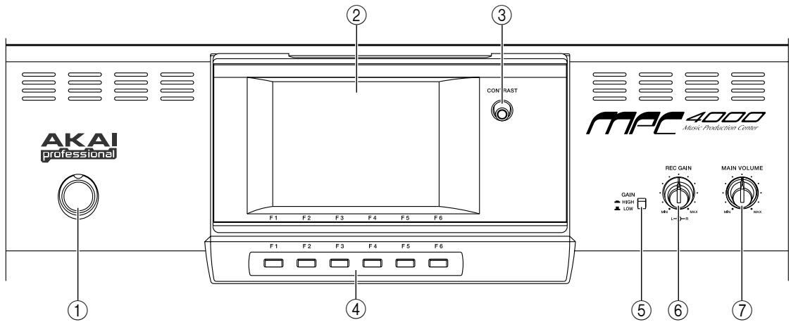
Upper part of the top panel
① [POWER] button: This switch turns the power on/off.
② Display: This is a backlit liquid crystal display (LCD). The angle can be adjusted in five positions.
③ [CONTRAST] knob: This knob adjusts the contrast of the display.
(4) [F1]–[F6] keys: These keys are used to access the pages indicated in the bottom row of the display, and to execute the function assigned to each key. The actual function will depend on the screen that is currently displayed.
[5] [GAIN] switch: This switch selects the gain of the signal that is input from the [LINE/MIC] jacks or [PHONO] jacks. Set this to HI if mics are connected to the [LINE/MIC] jacks, or to LOW if a line-level device such as a CD player is connected. When inputting signals from a turntable connected to the [PHONO] jacks, always set this switch to LOW.
[REC GAIN] knob: This knob adjusts the recording level of the signal that is input from the [LINE/MIC] jacks or [PHONO] jacks. The inner knob adjusts the right channel, and the outer knob adjusts the left channel.
[MAIN VOLUME] knob: This adjusts the output level of the signal that is sent from the [MAIN OUT] jacks.
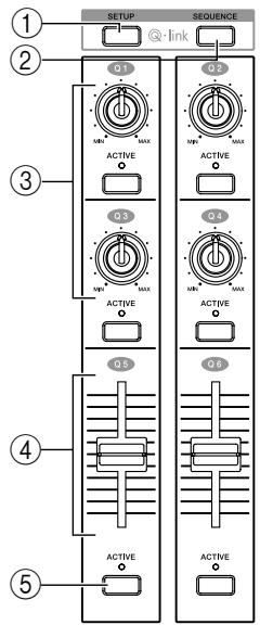
Q-LINK section
You can assign internal MPC4000 parameters or MIDI messages to the knobs and sliders of this section, and control them in realtime.
① [SETUP] key: This key accesses the Q-LINK Setup page, where you can select the parameter that will be assigned to each knob and slider.
② [SEQUENCE] key: This key accesses the Q-LINK Sequence page, where you can record Q-LINK values and play them back automatically.
(3) [Q1]–[Q4] knobs: A control change or any of different internal parameters can be assigned to these knobs, allowing you to control values in realtime.
④ [Q5]/[Q6] sliders: These sliders are used to control internal parameters and control changes in realtime. The parameters and control changes that can be assigned to the sliders are the same as for the Q-LINK control knobs.
⑤ [ACTIVE] keys: These keys specify whether knob/slider operations will take priority over the events recorded in the sequencer. If these keys are on (LED lit), the actual positions of the knobs/sliders will take priority even if changes for the same parameters are recorded in the sequencer.
Pad section
In this section you can operate the velocity-sensitive pads, and make various settings for them.
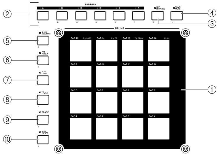
① Pads 1-16: These are velocity sensitive pads used to play the MPC4000's sampler section and external MIDI devices. In some pages, these pads are used to select tracks or sequences.
② PAD BANK [A]–PAD BANK [F] keys: These keys switch the combination of sounds/note numbers that are assigned to pads 1–16 (the “pad bank”). The PAD BANK [A]–PAD BANK [F] keys select pad banks A–F respectively.
(3) [NEXT SEQUENCE] key: This key accesses the Next Sequence page, where you can use the pads to switch sequences in realtime.
④ [TRACK MUTE] key: This key accesses the Track Mute page, where you can use the pads to switch track muting in realtime.
[Q-LINK SEQUENCE] key: This key is an on/off switch for the Q-LINK Sequence function, which lets you play back Q-LINK values.
[6] [PAD ASSIGN] key: This key accesses the Pad Assign page, where you can change the note numbers that are assigned to the pads.
[FULL LEVEL] key: When this key is on (LED lit), sounds will be played at the maximum velocity (127) regardless of how strongly you strike the pads.
[16 LEVEL] key: When this key is on (LED lit), the sound of a specific pad will be assigned to all sixteen pads, allowing you to play the sound using sixteen gradations of velocity.
[ERASE] key: This key is used to erase events from within a track. Events can be erased in realtime while overdubbing, or individual events can be erased while the sequencer is stopped. For details, refer to p.22, 24, 27.
[NOTE REPEAT] key: When you hold down this key and press one of the pads, the sound assigned to that pad will be triggered repeatedly. The interval of the repetitions can be adjusted in a range from an 8th note to a 64th note triplet.
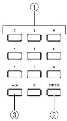
Data entry section
This section lets you input numerical values.
① Numeric keys: These keys are used to input a numerical value directly into the selected field in the display.
(2) [ENTER] key: This key finalizes the value that was input by the numeric keys.
③ [- / + ] keys: These keys switch the sign (negative/positive) of the value that was input by the numeric keys.
Mode section
In this section you can switch between the various modes of MPC4000. Each key corresponds to the following mode.

① [RECORD] key: Record mode
② [SAMPLE] key: Sample mode
③ [PROGRAM] key: Program mode
④ [MULTI] keyMulti mode:
⑤ [MIXER] key: Mixer mode
⑥ [EFFECT] key: Effect mode
⑦ [SAVE] key: Save mode
⑧ [LOAD] key: Load mode
[GLOBAL] key: Global mode
[SONG] key: Song mode
[11] [MISC.] key: Misc. mode
[2] [MIDI] key: MIDI mode
[3] [MAIN] key: Main mode
14 [SEQ EDIT] key: Sequence Edit mode
15 [STEP EDIT] key: Step Edit mode
Control section
In this section you can perform basic sequencer operations such as locate/playback/record, and change the setting of various fields that are shown in the display.
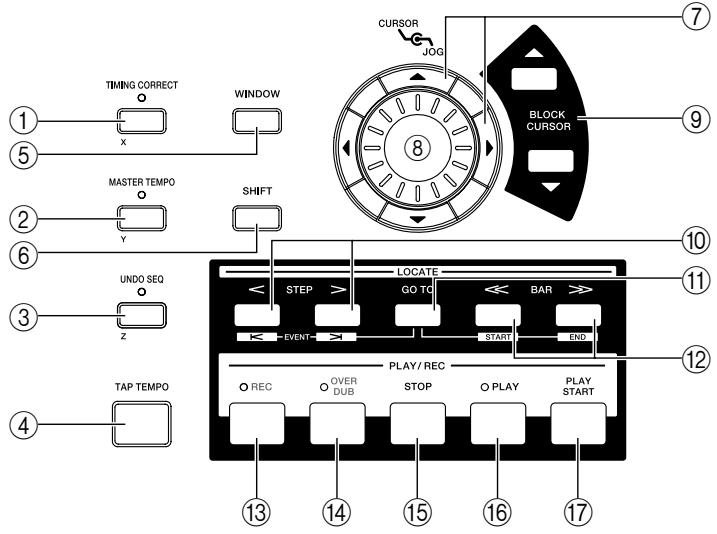
(1) [TIMING CORRECT] key: This key is an on/off switch for the Timing Correct function, which corrects the timing of the note data that is being recorded in the sequencer. Timing Correct is enabled if the LED is lit, and the note data will be recorded at timing intervals of the currently selected note value.
(2) [MASTER TEMPO] key: This key selects the tempo source used for sequencer playback. If the LED is lit, all sequences will play at a common tempo. If the LED is dark, each sequence will play at its own tempo.
[UNDO SEQ] key: This key is used to cause events recorded in the sequencer to revert to their previous condition (the Undo function). The LED will light if Undo is available.
(4) [TAP TEMPO] key: This key is used to manually specify the tempo. Striking this key repeatedly will automatically set the tempo to the corresponding quarter-note interval.
⑤ [WINDOW] key: This key opens a window for making detailed settings. When you move the cursor to a specific field in the display and press this key, a window for that field will open. Press this key once again to close the window.
[SHIFT] key: This key is used in conjunction with other keys as a shortcut for certain functions, or to specify a range.
⑦ CURSOR [▲]/[▼]/[▲]/[▶] keys: These keys are used to move the cursor up/down/left/right in the display.
[DOG] dial: This dial adjusts the value of the parameter at which the cursor is located.
⑨ BLOCK CURSOR [▲]/[▼] keys: If the currently displayed page is divided into blocks, these keys move the cursor upward or downward between blocks.
STEP [ ] / [> ] key: These keys are used to move backward or forward within the sequence in units of one step. By holding down the [GO TO] key and pressing one of these keys, you can move to the event that is immediately before or after the current location.
⑪ [GOTO] key: This key is used to move the current location to a specified locate point, or to access the Locate window where you can register a locate point. For details on the Locate window, refer to page 14.
12 BAR [ < ] / [>>] keys: These keys are used to move backward or forward within the sequence in units of one measure. By holding down the [GO TO] key and pressing one of these keys, you can move to the start point or end point of the sequence.
[REC] key: When you hold down this key and press the [PLAY] key or [PLAY START] key, recording on the sequencer will begin. If the track contains previously-recorded events, they will be replaced by the new events.
[OVER DUB] key: This key has essentially the same function as the [REC] key, with the difference that newly recorded events will be added to the track without erasing the previously-recorded events.
[STOP] key: This key stops sequence playback or recording.
[PLAY] key: This key starts playback or recording from the current location within the sequence.
[PLAY START] key: This key starts playback or recording from the start point of the sequence.
Rear panel

① [SIGNAL GND] terminal: Connect the grounding wire of your turntable to this terminal.
② REC IN [PHONO] jacks: These are turntable input jacks.
- A phono equalizer will be applied to compensate the frequency response of the signal that is input to these jacks. Do not connect any device other than a turntable to these jacks.
③ REC IN [LINE/MIC] jacks: Mics or line level devices such as CD players can be connected to these jacks. Either XLR or phone plug cables can be connected. Balanced phone plug connections are also supported.
(4) [INPUT SELECT] switch: This switch selects the input signal. The signal from the [PHONO] jacks will be input if this switch is in the PHONO position, and the signal from the [LINE/MIC] jacks will be input if this switch is in the LINE/MIC position.
[MAIN OUT] jacks (XLR): These are balanced main output jacks that output the signal from the sampler section and the metronome click sound. Cables with XLR plugs can be connected.
[MAIN OUT]acks (phone): These are balanced main output jacks for connecting phone plug cables. They output the same signal as the [MAIN OUT] (XLR) jacks.
(7) [MIDI IN I]/[MIDI IN II] connectors: These connectors receive MIDI messages. MIDI messages can be received independently at each connector.
[MITIDI OUT A]-[MITIDI OUT D] connectors: These connectors transmit MIDI messages. MIDI messages can be transmitted independently from each connector A-D.
[USB] connector (slave): This connector allows the MPC4000 to be connected to a computer (Windows/Macintosh) for file transfer or remote control.
⑩ SCSI connector: This is a D-sub half-pitch 50-pin (high pitch 50 pin) connector for connecting SCSI-compatible devices. SCSI-type CD-ROM drives or hard disks can be connected. For details on SCSI connections and supported devices, contact your Akai dealer or Akai Professional M.I Service Department.
[FOOT SWITCH 1]/[FOOT SWITCH 2] jacks: Foot switches can be connected to these jacks to perform operations such as punch-in/out.
[2] [SMPTE IN] jack: This jack receives SMPTE time code (LTC) from an external device. Use this when you want an external device to be the time code master, and the MPC4000 to operate in synchronization with the external device.
[3] [SMPTE OUT] jack: This jack transmits SMPTE time code from the MPC4000 to an external device. Use this when you want the MPC4000 to be the time code master, and an external device to operate in synchronization with it.
[DIGITAL IN] jack: This is a coaxial type digital input jack. The digital output jack of a CD player or DAT can be connected to this.
[DIgITAL OUT] jack: This is a coaxial type digital output jack. It outputs the same signal as the [MAIN OUT] jacks.
[WORDCLOCK IN] jack: This is a BNC jack for receiving a word clock signal from an external device. Use this when the MPC4000's digital audio signal processing must be synchronized with that of an external digital recorder or digital mixer.
(17) [TERMINATOR] switch: This is an on/off switch for word clock termination. If a word clock signal is being supplied from an external device to the MPC4000's [WORDCLOCK IN] jack, you will normally set this to the ON position.
18 Option slot: This slot allows a separately sold interface card to be installed.
19 Power supply connector: Connect the included power cable to this connector.
* You must use the cable that is included with the MPC4000.
Front panel
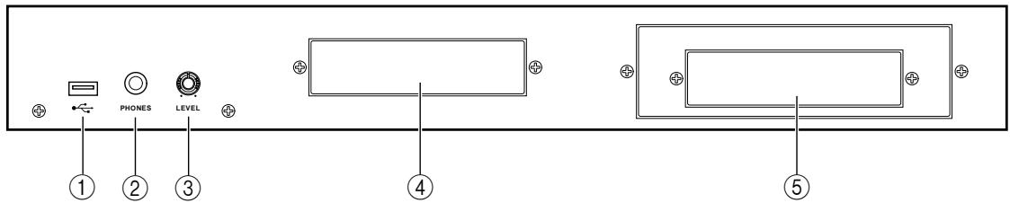
① [USB] connector (host): This USB connector allows a USB-type CD-ROM drive, removable drive, or USB keyboard etc. to be connected. Unlike the rear panel USB connector, this connector cannot be connected to a computer. For details on USB connections and supported devices, contact your Akai dealer or Akai Professional M.I Service Department.
(2) [PHONES] jack: This is a stereo phone jack for connecting headphones. It outputs the same signal as the [MAIN OUT] jacks.
③ [PHONES LEVEL] knob: This is a dedicated volume knob for the [PHONES] jack.
④ 3.5 inch bay: An ATAPI-type internal hard disk or ZIP drive can be installed in this bay.
⑤ 5 inch bay: An ATAPI-type CD-ROM drive can be installed in this bay. A 3.5 inch drive can also be installed here. For compatible devices, contact your Akai dealer or Akai Professional M.I Service Department.
Note: If a removable disk drive is installed in the MPC4000, protect the disk by taking it out of the drive when you are not actually loading or saving data on it.
Audio/MIDI connections
When connecting external audio or MIDI devices to the MPC4000, make connections as shown in the diagram below.

Connecting USB devices
[USB] connectors are provided on the front panel and the rear panel of the MPC4000.
The rear [USB] connector (slave) can be connected to a USB-equipped computer (Windows or Macintosh), allowing you to control the MPC4000 from an editing program.
The front panel [USB] connector (host) can be connected to a USB storage device such as a hard disk or CD-ROM drive to save the MPC4000's internal data, or to a USB-compatible ASCII keyboard for easier input of names.
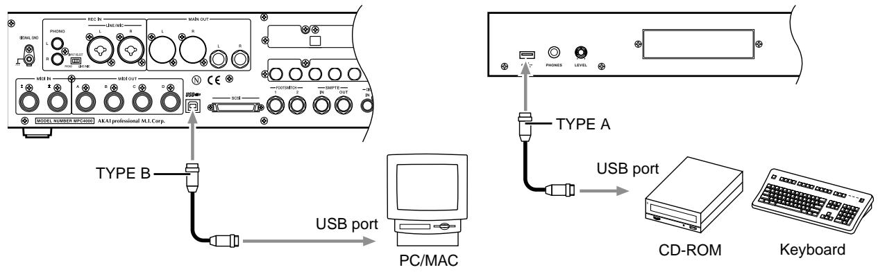
USB devices support "hot plugging," which means you can connect or disconnect them even when the power is on. When you connect a USB device, the MPC4000 will recognize it automatically.
Connecting SCSI devices
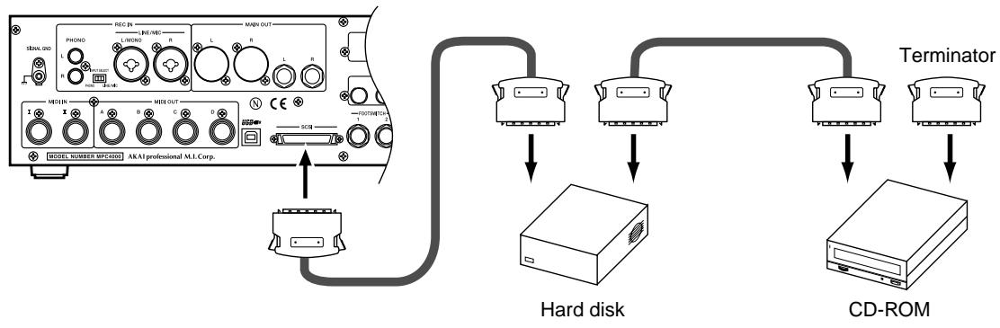
The MPC4000's rear panel has a [SCSI] connector that lets you connect devices such as a SCSI hard disk. Up to seven SCSI devices (including the MPC4000 itself) can be connected, and each device is distinguished by its own SCSI ID number. Please observe the following cautions when connecting SCSI devices.
- The power of all devices must be turned off before you connect SCSI devices.
- Set the ID numbers of the SCSI devices so that they do not conflict with each other.
- At the factory, the MPC4000 is set to a SCSI ID of 6. However, you may change this if necessary. For details, refer to the PDF reference manual.
- Use high-quality SCSI cables (high impedance cables) to connect the devices.
- You must use a terminator to terminate the last device in the SCSI chain. (The MPC4000 contains an active terminator that is always on.)
- You must turn on the power in the order of SCSI devices → MPC4000.
2 Introducing the MPC4000
This chapter describes how the MPC4000 is structured, and explains the special terms you will need to know when using it. This chapter also explains the user interface of the MPC4000, and basic operating procedures.
How the MPC4000 is structured
Broadly speaking, the MPC4000 consists of the following three sections.
- Sampler
- Sequencer
- Pads/controllers
These sections internally communicate with each other using MIDI events (performance data). The following diagram shows how MIDI events will flow within the MPC4000 when it is in the default state.
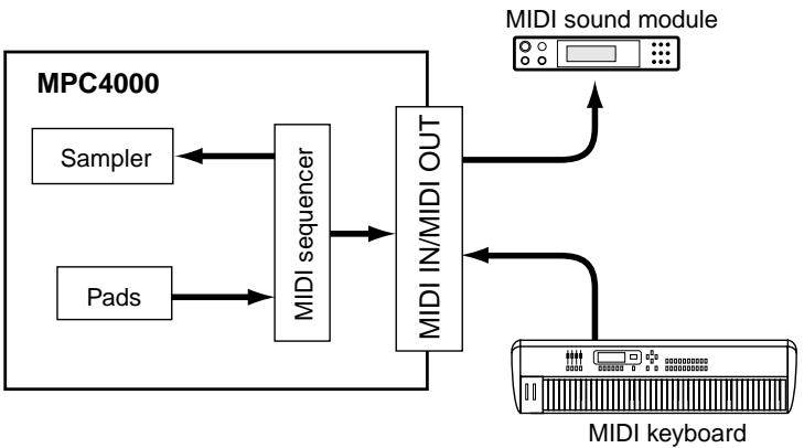
A MIDI note number is assigned to each pad on the top panel, and when you strike a pad, the corresponding note-on message is sent to the sequencer section or the [MIDI OUT] connectors.
The sequencer section records the MIDI events that it receives from the pads or the [MIDI IN] connectors. When you play back the sequencer, these MIDI events are sent to the sampler section or the [MIDI OUT] connectors.
The sampler section receives MIDI events from the sequencer section, pads, and [MIDI IN] connectors, and produces sounds.
Now let's take a closer look at how each section is structured.
Sampler section
Samples
The sounds of the sampler section are created from pieces of audio waveform data called "samples." The MPC4000 can use samples with 16-bit or 24-bit quantization and 44.1 / 48 / 96kHz sampling rates (stereo or monaural).
Programs
The units of sound used by the sampler section are called "programs." A program consists of one or more samples (waveform data) together with filter, envelope, LFO and other parameters. The MPC4000 has two types of program.
- Drum programs
This type of program assigns a different sample to each note number. You will use drum programs mainly to play drum or percussion kits, or to play phrase samples.
A drum program provides "zones" (areas) to which you can assign up to four samples for each note number. You can specify the range of velocities that will play each zone. This lets you layer multiple samples, or switch samples by velocity.
When you use the pads to play drums, you will use one of these drum programs. The program will be played according to the note numbers that are assigned to the pads.
The following diagram is an example of a drum program in which one sample is assigned to each pad.
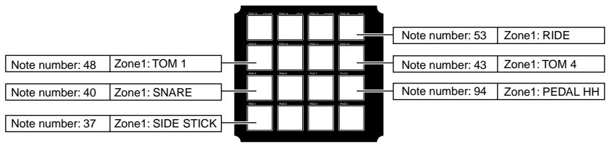
The following diagram is an example where two samples are assigned to each pad number. For some note numbers, two samples are crossfaded by velocity.

Key group programs
This type of program uses a region of consecutive note numbers to play a sample at varying pitches. You will use key group programs to play sounds such as bass or piano.
The region of note numbers to which one sample is assigned is called a "key group," and the range of notes that play a key group is called the "key span."
Just as for a drum program, you can use up to four zones in a key group.
The following diagram is an example of a single sample assigned to a key group that consists of only one zone. The key span for this key group is specified as the entire keyboard.

The following diagram shows an example using two key groups, each with their own key span. The two key groups are cross-faded by pitch.

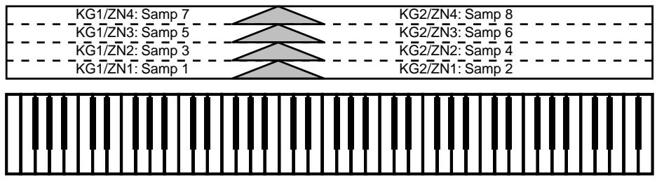
The following diagram shows an example using two key groups, each with four zones. The two key groups are switched by pitch.


The following diagram also shows two key groups, each with four zones. However, the difference here is that the two key groups are crossfaded.
Multi
A "multi" consists of performance settings for one or more programs that allow the program(s) to be played from the pads or sequencer.
Within a multi, a "part" refers to each of the areas for which you make individual settings for a program. One multi lets you use up to 128 parts.
To play the MPC4000's programs, you assign programs to parts within the multi, and specify the level, output destination, pan, and effect send level etc. for each part.
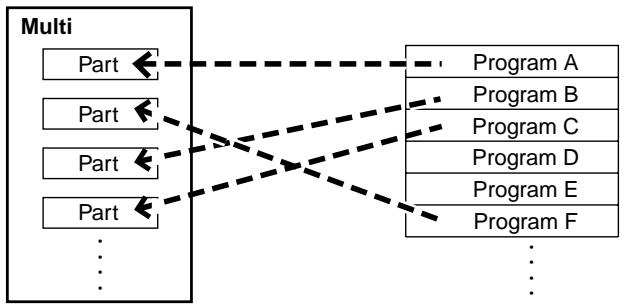
The MPC4000's internal memory can store numerous multis. By loading a different multi from internal memory, you can instantly switch the settings of all parts.
Sequencer section
Tracks and sequences
"Sequences" are the basic unit from which an MPC4000 song is created. The MPC4000 lets you create up to 128 sequences in internal memory, and you can specify the length (1-999 measures), tempo, and time signature separately for each sequence.
Each internal area within a sequence that records a performance you play on the pads or a MIDI keyboard is called a "track." A sequence consists of 128 tracks.
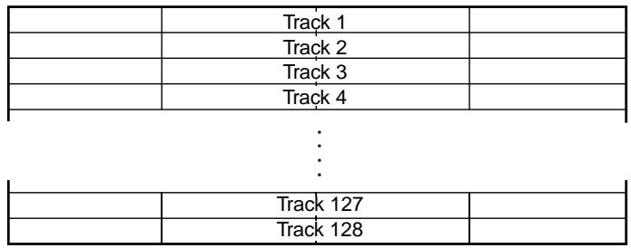
The MIDI events recorded in the 128 tracks can be sent to the sampler section or transmitted from the [MIDI OUT] connectors. You can freely select the output destination for each track.
Songs
You can arrange multiple sequences in the desired playback order to create a "song." To create a song, you specify the number of the sequence, and how many times it will be played. By specifying up to 250 such "steps," you can create a song consisting of sequences placed in the desired order.
A song you create can be saved as is, or can be converted into a sequence and written.
| Step 1 | Step 2 | Step 3 | Step 4 | Step 5 |
| Sequence A | Sequence B | Sequence C | Sequence A | Sequence A (repeat x 1) |
Pad section
Pads 1-16
The top panel contains sixteen velocity-sensitive pads. These pads are a user interface that corresponds to the keyboard of a synthesizer. However, the pads differ from a MIDI keyboard in that you can freely assign a note number to each pad.
If you have selected a drum program, you can assign a different drum/percussion sound to each pad and play them. If you have selected a key group program, you can assign the necessary pitches to the pads to play a melody.
Pad banks
A set of note numbers assigned to pads 1-16 is called a "pad bank." The MPC4000 provides six pad banks, A-F. By switching pad banks you can use the sixteen pads to play 96 different sounds (or different pitches).
About the memory of the MPC4000
The programs, samples, multis, sequences, and songs we have discussed so far are all held in the internal memory of the MPC4000. However, internal memory is volatile, and will be lost when you turn off the power.
This means that if you want to keep your data, you must save it on an external or internal storage device (e.g., hard disk).
You can store data to (or load data from) a storage device in units of programs, samples, multis, sequences, and songs.
You also have the option of loading/saving the sequences/songs of the sequencer section and the programs/samples/multis of the sampler section as a single collection of data.
Basic operation on the MPC4000
Here's how to perform the basic operations that are common to each screen of the MPC4000.
Switching modes
In order to perform an operation on the MPC4000, you must first use the keys of the mode section (→ p.3) to access the desired mode.

The screen will switch according to the mode you selected. The following illustration shows the Main mode screen that you will see when you turn on the power. Operations for the Sequencer section are mainly performed in this screen. If a different screen is shown, you can press the [MAIN] key of the mode section to access this screen.
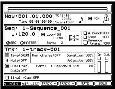
Accessing a page
Each mode consists of multiple screens. Each of the screens in a mode is called a "page." Each page is divided into blocks that contain related items, and each block contains one or more items that you can set. An area in which you can change the setting of an item is called a "field"
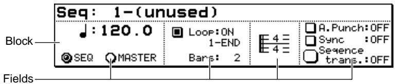
Operating the function keys
Six function keys ([F1]–[F6] keys) are placed below the display in the top panel.
The function of these function keys will change according to the mode or page you select. The lowest line of the display will indicate the function key functions that can be used in the currently selected mode and page. By pressing the corresponding function key, you can execute the displayed function.
For example in the Main mode Main page, the following functions are assigned to the function keys.

In this page, pressing the [F2] key (TR LIST) will access the Main mode Track List page. Pressing the [F3] key (TRACK + ) or [F4] key (TRACK - ) will switch the track numbers displayed in the main page.
Editing a value
When you want to edit the value of a field in the screen, move the cursor (the highlighted area) to that field, and turn the [JOG] dial.
To move the cursor within a block, use the CURSOR [] /[▼] / [] / [] keys. To move the cursor directly to the block above or below, use the BLOCK CURSOR [] /[▼] keys.
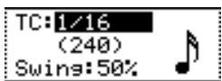
Place the cursor at the appropriate location, and turn the [JOG] dial to change the value of that field.
Accessing a popup window
Some items in the screen have a popup window that lets you set various options. To access the popup window, move the cursor to the field for that item, and press the [WINDOW] key.
As an example, here's how to access the clock function that is built into the MPC4000.
- Press the [GLOBAL] key, and then press the [F1] key (GLOBAL).
The Global page will appear.
- Use the CURSOR [Δ] / [] keys to move the cursor to the Date field, and press the [WINDOW] key.
The Set Date/Time popup window will appear.
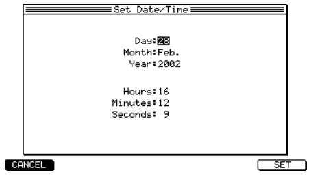
- Use the CURSOR [Δ] / [] keys to select the item that you want to set, and use the [JOG] dial to set the current date and time.
- Press the [F6] key (SET).
The popup window will close, and the specified date and time will be set for the internal clock.
Note: The specified date and time will be used as the time stamp when saving a file.
Hint: A popup window may also appear when you set the value of certain fields, or when you execute a function assigned to the [F1]–[F6] keys.
Editing a name
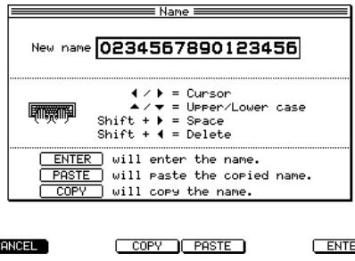
When you want to edit a sequence name or program name, move the cursor to the name field, and turn the [JOG] dial to access the following popup window.
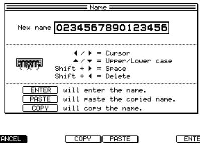
In this window, use the CURSOR [▲]/[▶] keys to move the cursor to the character that you want to edit, and turn the [JOG] dial to select a character. When you are finished, press the [F6] key (ENTER) to finalize the name.
Locating to a specific place
The MPC4000 gives you various ways to change the current time location within a sequence or song.
- Using the Now field to specify the measure/beat/tick
Screens such as the main page have a Now field that shows the current measure/beat/tick. You can move the cursor to any of the following fields and turn the [JOG] dial to change the current location.
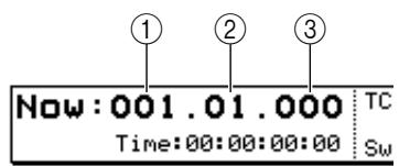
① Measure field
② Beat field
③ Tick field
These fields specify the current location in measures, beats, and ticks. In the Tickfield, you can use the CURSOR [▲]/[▶] keys to switch the tick unit (10 ticks/1 tick).
- Using the STEP [< ][> keys/BAR [ < ] / [ > > ] keys/[GO TO]keys
If the MPC4000 is in a state in which you can play back a sequence or song, you can use the STEP [<] / [>] keys, BAR [<] / [>] keys, and [GO TO] key to move the current location forward or backward. Each key has the following operation.
| Keys | Result |
| STEP [<=]/[>] keys | Move the current location forward or backward by the amount you specified in Timing Correct. |
| [GO TO] key + STEP [<=]/[>] keys | Move the current location in steps of the events recorded in the track (refer to Reference for the type of events). |
| BAR [<=]/[>] keys | Move the current location in step of one measure. |
| [GO TO] key + BAR [<=]/[>] keys | Move to the beginning (BAR [<=] key) or end (BAR [=>] key) of the sequence. |
Hint: You are free to change the functions assigned to these keys. For details, refer to the PDF reference manual.
- Using the Locate popup window
If the MPC4000 is in a state in which you can play back a sequence, you can press the [GOTO] key to access a popup window where you can perform locate operations. IN this window you can memorize the current location as a locate point, or specify a locate point in measures/beats/ticks.
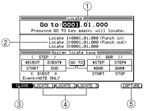
① Go to field: Here you can specify the locate destination in measures/beats/ticks.
② Locate 1 field – Locate 3 field: Here you can specify locate points. The MPC4000 can remember up to three locate points.
③ [F1] key (CLOSE): This key closes the window and locates to the position of the Go to field.
[F2] key (LOCATE 1)-(F4] key (LOCATE 3): These keys locate to the corresponding locate points.
[5] [F6] key (CAPTURE): This key inputs the current location of the sequence into the currently selected field.
Hint: Locate points 1/2 are also used as the auto punch-in/out points (→ p.24) .
Playing a program
Immediately after you have turned on the power of the MPC4000, the internal memory does not contain any programs. In order for you to use pads 1-16 to play a program from the sampler section, you must load a program from an external or internal storage device into memory, and assign it to a part. Here's how to do this.
- If you are using an external storage device, make sure that the storage device is connected correctly and that its power is turned on.
For details on connecting storage devices, refer to p.6, 7.
- Press the Load section [LOAD] key.
The MPC4000 will enter Load mode.
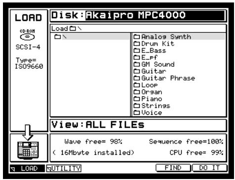
- Move the cursor to the Disk block in the upper part of the page, and turn the [JOG] dial to access the following popup window.
In this window you can select the storage device from which you want to load a program.
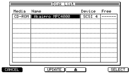
- Use the CURSOR [Δ] / [] keys or the [JOG] dial to select a storage device.
5. Press the [F5] key (SELECT).
The contents of the storage device will be displayed as a tree in the file list block in the upper part of the screen.
![AKAI MPC4000 - Press the [F5] key (SELECT). - 1](/content/2025/01/152367/images/171419be0163f1d12e6e5fc0944cfe58643eef099f6bb38ef3f913bf65ad64e7.jpg)
6. Move the cursor to the View field in the center of the display, and use the [JOG] dial to select "PROGRAM."
In the View field you can select the type of files that will be displayed in the file list. If you choose PRO-GRAM, only program files will be displayed.
7. Move the cursor to the file list, and use the CURSOR [] /[▼] /[▲] /[►] keys to select the file you want to load.
In the file list, use the CURSOR [] / [] keys to move between levels, and the CURSOR [] / [] keys to select a file or folder within the current level.
For example when you first access a storage device, the left side of the file list will by the [ROOT] folder, and the right side will display the files or folders contained in the [ROOT] folder.
![AKAI MPC4000 - Move the cursor to the file list, and use the CURSOR [] /[▼] /[▲] /[►] keys to select the file you want to load. - 1](/content/2025/01/152367/images/76dcdd27a94c0275e94d89fddcfe02fa5a9e6ba380e5873da49b49c86cb1509e.jpg)
When the [ROOT] folder is selected, press the CURSOR [▶] key once to move the cursor to the right side of the file list.
![AKAI MPC4000 - Move the cursor to the file list, and use the CURSOR [] /[▼] /[▲] /[►] keys to select the file you want to load. - 2](/content/2025/01/152367/images/8644de68c803df15e0d8f5a61de47fd728758bacda0ed1bb74aa3200876bd85c.jpg)
If you want to move to a level below the [ROOT] folder, use the CURSOR [] /[▼] keys to select the folder and then press the CURSOR [] key to scroll the tree display to the right. The right side of the file list will now show the contents of the newly selected folder. (To return to the next upper level, press the CURSOR [] key.)
![AKAI MPC4000 - Move the cursor to the file list, and use the CURSOR [] /[▼] /[▲] /[►] keys to select the file you want to load. - 3](/content/2025/01/152367/images/ae96a8c9641480745c38fd366d5d491bddb6b024295c5a7bccd82576fba70460.jpg)
To select a file from the currently selected level (folder), use the CURSOR [Δ] /[▼] keys to move the cursor to the folder.
8. When you have selected a program file, press the [F6] key (DO IT button).
The Load a Program window will appear.
![AKAI MPC4000 - When you have selected a program file, press the [F6] key (DO IT button). - 1](/content/2025/01/152367/images/de69435945fc812c478d14dd02c2c4d350d8f722fabd422c6ba4a1943c5d09b0.jpg)
- Make sure that the Load field is set to WITH SAMPLES, and press the [F5] key (DO IT button).
The MPC4000 will load the program. If the Load field is set to WITH SAMPLES, the necessary samples will be loaded into memory along with the program.
The program has now been loaded into memory. In order to play the program, you will need to assign it to a part.
- Press the mode section [MAIN] key.
The main page will appear. Here you can create and play sequences.
![AKAI MPC4000 - When you have selected a program file, press the [F6] key (DO IT button). - 2](/content/2025/01/152367/images/de8883de7dd169d5e2fda5e82c9a3ff7f7ce3f469dec4e6cdc4ffe6a2c8fd6f9.jpg)
- In the Track block located in the middle of the page, make sure that the Out1 field is set to PART, and the PART field is set to a value of 1.
![AKAI MPC4000 - When you have selected a program file, press the [F6] key (DO IT button). - 3](/content/2025/01/152367/images/4b6ad361db4f75239755a730524ff9e6ab085727716c523121147f97ba5a5811.jpg)
- Move the cursor to the right side of the PART field, and turn the [JOG] dial.
The following popup window will appear.
![AKAI MPC4000 - When you have selected a program file, press the [F6] key (DO IT button). - 4](/content/2025/01/152367/images/24de888a034b03a3253bb833ac02980f190a8350160fb3666681ece9e99a6156.jpg)
- Turn the [JOG] dial to select the program, and press the [F6] key (SELECT) to finalize the program.
The program has now been assigned to part 1. Now you can strike the pads to play the selected program.
![AKAI MPC4000 - When you have selected a program file, press the [F6] key (DO IT button). - 5](/content/2025/01/152367/images/dd7c47d68428ba1f1d1ae8848362453b62247bb23e152394460252ad260cfc7d.jpg)
3 Creating and editing a sequence
This chapter explains how to record MIDI events into a sequence, and how to edit the recorded MIDI events.
About sequences
A "sequence" is the smallest unit from which an MPC4000 song is made up. You can specify the length (1-999 measures), tempo, and time signature of each sequence. On the MPC4000, you can create a song that consists of only one sequence, or you can create separate sequences and then arrange them later into a complete song.
The internal memory of the MPC4000 contains 128 sequences. When you turn on the power, all sequences will be empty. To create a new sequence, you must select an empty sequence and record or edit it.
Note: The contents internal memory will be cleared when you turn off the power, and the sequences you create will be lost. If you want to keep your sequences, you must save them to a storage device before turning off the power.
A sequence consists of 128 tracks. Each track can independently record the performance data (MIDI events) such as note-on/off and control change that is sent from the pads and from the [MIDI IN I]/[MIDI IN II] connectors.
| Track 1 | ||
| Track 2 | ||
| Track 3 | ||
| Track 4 |
:
.
| Track 127 | |
| Track 128 |
There are two types of track.
- DRUM...... This type of track lets you view and edit the recorded MIDI events in a matrix-type graphic editor ( → p.27). This type of track is convenient for drum or percussion sounds.
- INST. This type of track lets you view and edit the recorded MIDI events in a piano-roll type graphic editor (→ p.27) . This is convenient for pitched sounds such as bass or piano.
Hint: You are free to change the track type even after MIDI events have been recorded in the track.
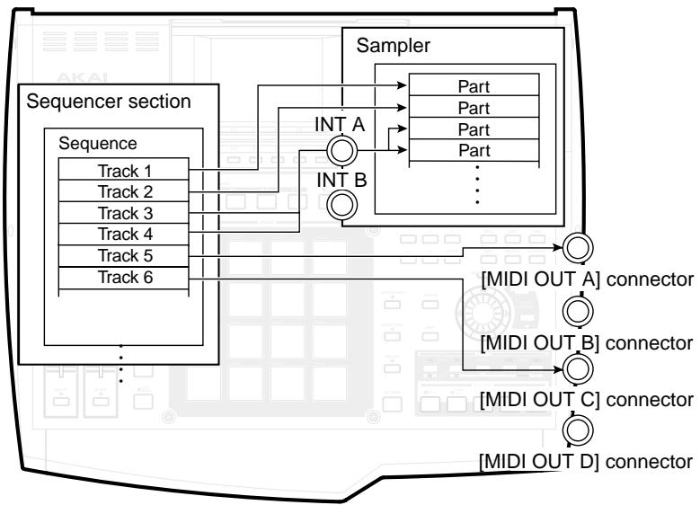
The recorded MIDI events are sent to the output destination that you specify for each track. You can choose from the following outputs.
- [MIDI OUT A] connector - [MIDI OUT D] connector
- INT-A/INT-B (virtual MIDI reception ports of the sampler section)
- Specific parts of the sampler section
Preparations for creating a sequence
Before you can record MIDI events in a track, you must specify certain parameters such as the number of measures, the time signature, and the tempo.
1. Press the [MAIN] key.
The main page will appear. Most of the steps involved in creating a sequence are performed in this page. Set the parameters of the sequence in the sequence block described below.
![AKAI MPC4000 - Press the [MAIN] key. - 1](/content/2025/01/152367/images/d574510b3032e05dad68a650b446868037fb268c2b4aa19bc03f910b6823c7df.jpg)
① Position bar: This shows the current position within the sequence. The full length of the bar graph corresponds to the length of that sequence.
② Now field: This shows the current position within the sequence in measures/beats/ticks.
③ Time field: This shows the current position within the sequence in hours/minutes/seconds/frames.
④ TC field: Here you can specify the note value that will be the minimum unit for timing correction (quantization).
⑤ Swing field: In this field you can specify the amount of "swing" by which the backbeats will be moved forward or backward. This will be displayed if you have selected 1/8, 1/16, 1/32, or 1/64 in the TC field.
⑥ Metronome field: Here you can switch the metronome on/off.
⑦ Seq field: Here you can select the sequence that you want to record or edit. The field will show the name of the currently selected sequence.
⑧ Tempo field: Here you can set the tempo of the sequence.
⑨ Loop field: Here you can switch loop playback on/off for the sequence. The field immediately below the Loop field lets you change the loop region. The loop region is shown as in the position bar.
10 Bars field: This opens the Change Bars popup window which lets you specify the number of measures in the sequence.
⑪ Time signature field: This opens the Change Time Signature popup window which lets you specify the time signature of the sequence.
12 A.Punch field: Here you can switch the auto punch-in/out function on/off.
③ Sync field: Here you can switch synchronization with external devices on/off.
⑭ Sequence trans. field: This lets you transpose an entire INST type track in a range of -12 -+12 semitones.
2. Move the cursor to the Seq field, and turn the [JOG] dial to select an empty sequence.
When an empty sequence is selected, the Seq field will indicate "x-(Unused)" (x will be a sequence number in the range of 1-128). An empty sequence will have default settings of time signature = 4/4 , measures = 2 , and tempo = 120 .
Hint: When you turn on the power, all sequences will be empty.
When you record MIDI events into a sequence, a sequence name of "Sequence_xxx" (where xxx is a sequence number in the range of 1-128) will be assigned automatically.
If the cursor is in the Seqfield, you can press the [WINDOW] key to access the Sequence popup window in which you can change the sequence name or edit the entire sequence ( → p.36).
3. Move the cursor to the Bars field, and turn the [JOG] dial.
The Change Bars popup window will appear. In this window you can specify the number of measures in the sequence.
- Turn the [JOG] dial to specify the number of measures, and then press the [F6] key (DO IT) to finalize the setting.
If you increased the setting, measures will be added after the current measure. If you decreased the setting, measures will be deleted from the end of the sequence.
- If you want to change the time signature of the sequence, move the cursor to the field that displays the time signature, and turn the [JOG] dial to access the following popup window.
![AKAI MPC4000 - Move the cursor to the Bars field, and turn the [JOG] dial. - 1](/content/2025/01/152367/images/68c36dcac2808f1ecd3cabaff067b5c888f84884693207cf5d5d41eb21aefbdf.jpg)
① Measure numbers: These indicate the measure numbers within the sequence.
② Time signature field: Here you can specify the time signature of the sequence. You can select a time signature in the range of 1/4–16/4, 1/8–16/18, 1/16–16/16, 1/32–32/32.
- Move the cursor to the time signature field, and turn the [JOG] dial to set the time signature.
Hint: By moving the cursor to the measure number and turning the [JOG] dial to specify a measure number, you can change the time signature mid-way through the sequence. You can select multiple measures by holding down the [SHIFT] key and pressing the CURSOR [▶] key. By changing the time signature in this state, you can change the time signature for all measures within the selected range.
- To finalize your changes, press the [F6] key (DO IT).
The popup window will close.
- If you want to make settings for the metronome, move the cursor to the Metronome field and press the [WINDOW] key.
The Metronome popup window will appear.
![AKAI MPC4000 - Move the cursor to the Bars field, and turn the [JOG] dial. - 2](/content/2025/01/152367/images/52c379a14f61e2fed1ca65e15afd89418005862436fa1fc9ea8549ecf76f8a89.jpg)
① Count in field: Specify how the pre-count will be sounded; OFF (pre-count=off), REC ONLY (only when recording), or REC+PLAY (when recording or playing).
② In Play field: Specify whether the metronome will sound while the sequence plays back.
(3) In Rec field: Specify whether the metronome will sound while the sequence is being recorded.
④ Rate field: Select the note value at which the metronome will sound. Choose from a range of 1/4 (quarter notes)–1/32(3) (thirty-second note triplets).
⑤ Wait for key field: If you turn this field ON, recording will begin the instant you press a pad or play your MIDI keyboard.
-
Make settings for each field, and then press the [WINDOW] key to close the popup window.
-
Make sure that the setting in the metronome field is ON.
-
Move the cursor to the tempo field, and turn the [JOG] dial to set the tempo as desired.
Hint: You can also set the tempo in realtime by tapping the [TAP TEMPO] key. This method is convenient when you want to match the tempo of a sequence to a sampled rhythm loop.
- If you want the sequence to loop as you play or record it, make sure that the setting of the Loop field is ON.
You are now finished with preparations for creating a sequence.
Realtime input
Here we will explain how your performance on the pads or a MIDI keyboard can be recorded on a track in realtime.
Realtime-recording a drum program
Here's how you can use the pads to play a drum program of the internal sampler or a rhythm machine connected to a [MIDI OUT] connector, and record your performance on an empty track.
- If you want to use a drum program of the internal sampler as your sound source, load the desired program into the internal memory of the MPC4000.
- If you want to use an external rhythm machine as your sound source, connect one of the [MIDI OUT A]-[MIDI OUT D] connectors to the MIDI IN connector of your MIDI sound source.
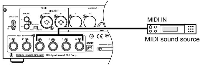
- Press the [MAIN] key to access the main page.
The Track block of the main page lets you select the track that you want to record, and specify the output destination.
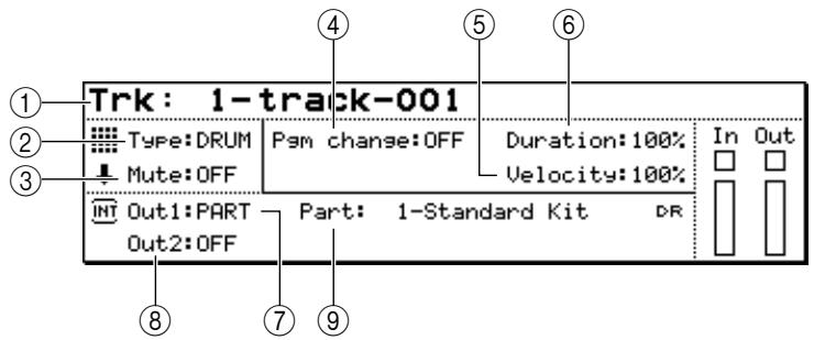
① Trk field: Selects the track that you want to record.
② Type field: Selects the type of track.
③ Play field: Switches the track on/off.
(4) Pgm Change field: Specifies the program change number that will be sent to the output destination when you play back the sequence.
⑤ Velocity field: Specifies an offset value of 0 - 200% that will be applied to the velocities of all note events when the track is played back.
Duration field: Specifies an offset value of 0 - 200% that will be applied to the duration of all note events when the track is played back.
⑦ Out1 field
Out2 field: These fields specify the output destinations of the track. By setting the OUT1 field and OUT2 field to different output destinations, you can transmit the events of one track to two output destinations.
⑨ Part field: Selects the part number(s) and program(s) to which the track will be sent. This field will be displayed only if PART is selected as the output destination for the Out1/Out2 fields.
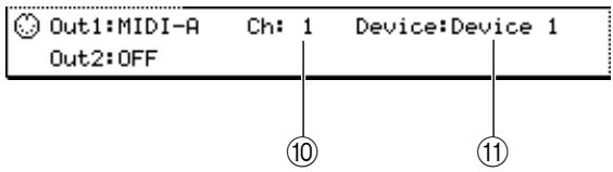
Ch field: Selects the MIDI channel(s) to which the track will be sent. This field will be displayed only if you have selected OUT-A-OUT-D or INT-A/INT-B as the output destination for Out1/Out2.
⑪ Device field: This field displays the device name that you have assigned to the devices connected to the [MIDI OUT A]–[MIDI OUT D] connectors. To assign a device name, move the cursor to this field and press the [WINDOW] key.
- Move the cursor to the Trk field, and turn the [JOG] dial to select the track that you want to record. Immediately after the power is turned on, all tracks in the sequence will be empty. Empty tracks will be assigned a track name of “(Unused).”
Hint: You can directly switch to the next upper or lower track by using the [F4] key (-) or [F5] key (+) . When you record MIDI events, a track name of "track_xxx" (where xxx is a track number 001-128) will be assigned. When the cursor is located at the Trk field, you can press the [WINDOW] key to access the Track popup window, where you can edit the track name or edit the entire track.
5. Make sure that the Type field is set to DRUM.
Hint: You can change this setting later as necessary.
6. Move the cursor to the Out1 field, and turn the [JOG] dial to select one of the following output destinations for the track.
PART............A specific part of the sampler section
OUT A .........[MIDI OUT A] connector
OUT B .........[MIDI OUT B] connector
OUT C.........[MIDI OUT C] connector
OUT D.........[MIDI OUT D] connector
INT-A.......Virtual MIDI input port A of the sampler section
INT-B.......Virtual MIDI input port B of the sampler section
You will normally choose PART if you want to play a program on the internal sampler, or OUT A-OUT D if you want to play an external rhythm machine.
The fields at the right of the OUT1 field will change as follows, depending on the output destination you selected.
INT Out1:PART Part: 1-NEW PROGRAM 01 DR
Out2:OFF
Out1:MIDI-R Ch:1 Device:Device 1 Out2:OFF
7. Move the cursor to the PART field or the Ch field, and turn the [JOG] dial to specify a part number (if you selected PART) or a MIDI channel (if you selected OUT A-OUT D).
When you strike the pads or play back the sequencer, the MIDI events will be transmitted to the part or MIDI channel you specified here.
Hint: If you selected a virtual MIDI port (INT-A/INT-B) of the sampler section as the output destination, specify the MIDI channel in the same way as described above. (Set it to match the MIDI receive channel of the part you want to play.)
You can use the same steps to set the Out2 field.
8. If you selected PART as the output destination, move the cursor to the right of the PART field and select the desired part number. Then move the cursor to the right again, select the drum program that you will play using this part.
The program will be assigned to the part you selected. For details on how to select a program, refer to p.14.
Hint: If desired, you can specify a program change number by moving the cursor to the Pgm Change field and turning the [JOG] dial. When you play back the sequence, the program change specified by this field will be sent to the output destination.
9. Strike the pads, and make sure that you can hear the program or MIDI sound source.
If you want to switch pad banks, press the PAD BANK [A]–[F] keys. The display for the In field will change according to the pad that you strike.
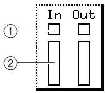
① : This will blink when a MIDI event is received.
② Bar: This will indicate the velocity value of the note event that is received. A longer bar indicates a larger velocity value.
Hint: The Out field shows the output status of the track. The contents of the display are the same as for the Infield.
10. Move the cursor to the TC field, and turn the [JOG] dial to select one of the following choices as the minimum timing interval at which note events will be recorded in the track.
1/8...8th notes, 1/8(3)...8th note triplets, 1/16...16th notes, 1/16(3)...16th note triplets, 1/32...32nd notes, 1/32(3)...32nd note triplets, 1/64...64th notes, 1/64(3)...64th note triplets,
OFF(96)...10 ticks (1/96th of a quarter note), OFF...Timing Correct=off (1/960th of a quarter note)
Timing Correct is a function that aligns the timing of note events to the specified note value interval as they are recorded in the track. If Timing Correct is turned on, the [TIMING CORRECT] key LED will light.
Hint: You may also record note events with Timing Correct turned off, and apply timing correct later. For details, refer to the PDF reference manual.
Use the [TIMING CORRECT] key to switch Timing Correct on/off.
- To start recording, hold down the [REC] key and press the [PLAY] key. Then play the pads while you listen to the metronome.
The [REC] key and [PLAY] key LEDs will light, and recording will begin on the currently selected track.
Hint: If you press the [PLAY START] key instead of the [PLAY] key, recording will always start from the beginning of the sequence. If you press the [OVER DUB] key instead of the [REC] key, the existing MIDI events will be kept, and the newly-recorded MIDI events will be added to them.
If the Loop field is set to ON/1-END, and you reach the end of the sequence, you will automatically return to the beginning and continue recording. At this time, the [OVER DUB] key LED will light instead of the [REC] key LED, and the newly-recorded MIDI events will be added.
- To stop recording, press the [STOP] key.
When you record or edit a track, the [UNDO SEQ] LED will light. If you press the [UNDO SEQ] key in this state, the track will return to the state in which it was before you modified it.
-
To hear the content that you recorded, press the [PLAY] key (or the [PLAY START] key).
-
To erase a note event that you input by mistake, hold down the [OVER DUB] key and press the [PLAY] key. Then immediately before the note event that you want to erase, hold down the [ERASE] key and press the corresponding pad.
The corresponding note event(s) will be erased as long as you hold down the pad.
![AKAI MPC4000 - Move the cursor to the TC field, and turn the [JOG] dial to select one of the following choices as the minimum timing interval at which note events will be recorded in the track. - 1](/content/2025/01/152367/images/5cebe8d38beb81847f4e6922e4ba71ee0c299066626e1665026edb7f26ee35c1.jpg)
![AKAI MPC4000 - Move the cursor to the TC field, and turn the [JOG] dial to select one of the following choices as the minimum timing interval at which note events will be recorded in the track. - 2](/content/2025/01/152367/images/cf8712d7a924b291a10ffa3b8a93d8da9c15d473a6a631b2d399bd0c629df366.jpg)
- Save the sequence if desired (→ p.38)
Realtime-recording a key group program
Here's how you can use the pads or a MIDI keyboard to play a key group program of the internal sampler or an external MIDI sound module, and record your performance.
- If you want to use a key group program as your sound source, load the desired program into the MPC4000's internal memory.
- If you want to use an external MIDI sound module as your sound source, connect your MIDI sound module to the MPC4000 ( → p.6).
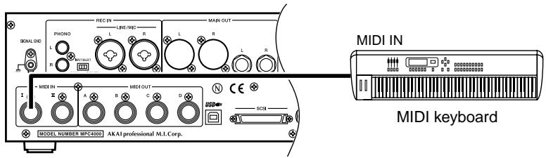
- If you want to use an external MIDI keyboard as the controller instead of the pads of the MPC4000, connect the MIDI OUT of your keyboard to the MPC4000's [MIDI IN I] connector or [MIDI IN II] connector.
You can use a MIDI keyboard connected to the [MIDI IN I]/[MIDI IN II] connectors to play programs and record sequences in the same way as when using the pads.
- Press the [MAIN] key to access the main page of Main mode.
- Move the cursor to the Trk field, and turn the [JOG] dial to select a new track.
-
Move the cursor to the Type field, and turn the [JOG] dial to change the setting to INST.
-
Move the cursor to the Out1 field, and turn the [JOG] dial to select the output destination for the track.
-
Move the cursor to the PART or Ch field, and turn the [JOG] dial to select the part number or MIDI channel.
If you selected PART as the output destination, you can also select the program that will be played by that part ( → p.14).
-
Strike the pads (or play your MIDI keyboard), and make sure that you can hear the program or MIDI sound source.
-
If you want to change the note numbers that are assigned to the pads, press the [PAD ASSIGN] key.
The Pad Assign page will appear, allowing you to change the note number for each pad.
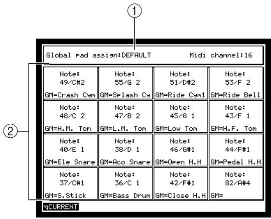
① Global pad assign field: Here you can change the note numbers that will initially be assigned to the pads. Choose either DEFAULT or CHROMATIC.
② Pads: This area shows the note number that is assigned to each pad.
Note: Some programs of the internal sampler are set up so that you can use the pads to play the program in an ideal configuration. The Global pad assign field will not be displayed for a track for which such a program is selected.
To change the pad assignments of this type of program, you will need to edit the program (→ p.85) .
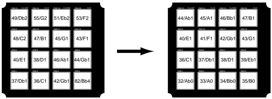
- Move the cursor to the Global pad assign field, and turn the [JOG] dial to change the setting to CHROMATIC.
The note numbers assigned to pads 1-16 will change. The initial DEFAULT setting (a pad assignment suitable for drum programs) will change to CHROMATIC (a pad assignment in which note numbers are assigned in semitone steps).
When you have finished making the setting, press the [MAIN] key to access the Main page.
Hint: You can press the PAD BANK [A] - [F] keys to switch the pitch range of pads 1-16.
-
Move the cursor to the TC field, and specify the desired timing correct setting.
-
To start recording, hold down the [REC] key and press the [PLAY] key. Then play the pads while you listen to the metronome.
The [REC] key and [PLAY] key LEDs will light, and recording will begin on the currently selected track. If the Loop field is set to ON/1-END, and you reach the end of the sequence, you will automatically return to the beginning and continue recording. At this time, the [OVER DUB] key LED will light instead of the [REC] key LED, and the newly-recorded MIDI events will be added.
Hint: If you operate the pitch bend wheel or controllers of your MIDI keyboard while recording, these continuously-variable events will be recorded along with the note events.
-
To stop recording, press the [STOP] key.
-
To hear the content that you recorded, press the [PLAY] key (or the [PLAY START] key).
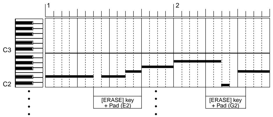
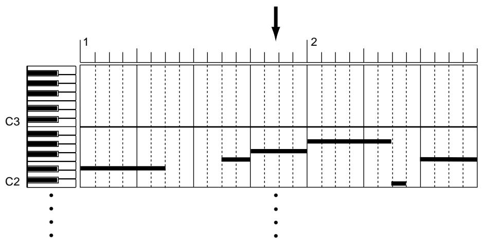
- To erase a note event that you input by mistake, hold down the [OVER DUB] key and press the [PLAY] key. Then immediately before the note event that you want to erase, hold down the [ERASE] key and press the corresponding pad or note.
If you erase the beginning (note-on) of a note event, that entire note event will be erased.
- Save the sequence if desired (→ p.38)
Auto punch-in/out
Use the auto punch-in/out function when you want to re-record just a specific portion of the performance you recorded on a track by playing the pad or your MIDI keyboard.
- Make sure that the main page is displayed.
You will make settings for the auto punch-in/out function in the Sequence block.
- Move the cursor to the A.Punch field, and press the [WINDOW] key to access the following popup window.
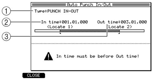
① Type field: Here you can choose one of the following three auto punch-in/out methods; PUNCH IN ONLY (only punch-in will occur automatically), PUNCH OUT ONLY (only punch-out will occur automatically), or PUNCH IN-OUT (punch-in/out will occur automatically).
② In time field: Specify the punch-in point in measures/beats/ticks.
③ Out time field: Specify the punch-out point in measures/beats/ticks.
- Make sure that the Type field is set to PUNCH IN-OUT.
If the setting is other than PUNCH IN-OUT, move the cursor to the Type field and turn the [JOG] dial to select PUNCH IN-OUT.
The graphic in the center of the popup window will change according to the punch-in/out type you select.
- Move the cursor to the In time field, and turn the [JOG] dial to specify the punch-in point.
The punch-in point is shown as a I symbol on the position bar of the main page.
- In the same way, move the cursor to the Out time field, and turn the [JOG] dial to set the punch-out point.
The punch-out point is shown as a symbol on the position bar of the main page.
-
Press the [F1] key (CLOSE) to close the popup window.
-
Make sure that the cursor is located at the A.Punch field, and turn the [JOG] dial to change the setting to ON.
This enables the auto punch-in/out function.
-
Move the cursor to the Trk field of the track block, and select the track on which you want to record.
-
Locate the sequence to a point earlier than the punch-in point.
-
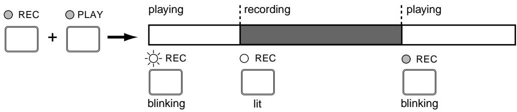
Hold down the [REC] key and press the [PLAY] key (or the [PLAY START] key).
The [PLAY] key LED will light, the [REC] key LED will blink, and the sequence will begin playing.
When you reach the punch-in point, the [REC] key LED will change from blinking to lit, and recording will begin.
When you reach the punch-out point, the [REC] key LED will go dark, and playback will resume.
- When you are finished recording, press the [STOP] key.
- Move the cursor to the A.Punch field, and change the setting to OFF.
This disables the auto punch-in/out function.
Step recording
Step recording allows you to input note events one by one while the sequence is stopped. This method is convenient when you want to record a phrase that would be difficult to play in realtime. Here's how to use the event list to step-record note events.
- In the main page, move the cursor to the Trk field and select the track that you want to step-record.
-
Select the output destination for the track, and specify the part number and program or MIDI channel that you want to play (→ p.19).
-
Press the [STEP EDIT] key.
The step edit page will appear, where you can input and edit MIDI events. In the center of the display you will see the event list that displays the MIDI events in the track.
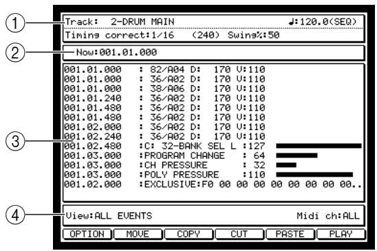
① Track field: Selects the track into which you step-record.
② Now field: Indicates the current location, and lets you specify the location at which you want to input a note event.
③ Event list: Displays the type and value of each MIDI event recorded in the track.
④ View field: Here you can select the type of MIDI events that will be displayed in the event list.
4. Press the [F1] key (OPTION) to access the Step Edit Option popup window.
In this popup window you can set options for step-recording.
![AKAI MPC4000 - Press the [F1] key (OPTION) to access the Step Edit Option popup window. - 1](/content/2025/01/152367/images/814bebb0af7e291c28ad1d8b243881b3e9b37a278474e4d3d012243ca4fd549c.jpg)
① Duration of recorded notes field: Selects how to specify the duration of the note events you input.
② Auto Step increment on key release field: Selects whether the current location will be advanced after you input a note event (YES) or whether you will remain at the previous location (NO).
- Move the cursor to the Auto Step increment on key release field, and turn the [JOG] dial to make the field show YES.
- Move the cursor to the Duration of recorded notes field, and turn the [JOG] dial to make the field show VALUE.
If you select TC VALUE, the note value you specified in the Timing correct field will be input here. The numerical value at the right of the field indicates the proportion of the duration relative to the timing correct value. If this value is 100% , the duration will be the same as the length of the note.
Hint: If you set this field to AS PLAYED, the duration of the note event will depend on the length that you continue pressing the pad or your MIDI keyboard. For details, refer to the PDF reference manual.
- Press the [F1] key (CLOSE).
The settings will be finalized and the popup window will close. - Move the cursor to the Timing Correct field, and set timing correct to the shortest note value that you will want to input (normally an 8th note or 16th note, etc.).
- Move the cursor to the measure/beat/tick areas of the Now field, and specify the location at which you want to begin step-recording.
- Press the [REC] key or the [OVER DUB] key.
The [OVER DUB] key LED will light, and you are now ready to begin step-recording.
- Strike the pads (or play your MIDI keyboard).
Note events will be recorded at intervals of the Timing Correct setting, and the current location will advance by the length of the note value. The velocity value will be the strength with which you strike the pad or your MIDI keyboard.
The recorded note events will appear in the event list as follows.
![AKAI MPC4000 - Press the [F1] key (OPTION) to access the Step Edit Option popup window. - 2](/content/2025/01/152367/images/af19225dc052d3dcc325c63db38769666007a2a2ab32c4b6f3c715f4b547f30e.jpg)
① Measure/beat/tick: Indicates the location at which the note event was recorded.
② Note number: Indicates the note number that was recorded, and the corresponding pad number (for a DRUM type track) or note name (for an INST type track).
③ D field: Indicates the duration of the note event in units of ticks.
④ V field: Indicates the velocity of the note event.
If you changed the setting at the right of TC VALUE in step 6, that proportion will determine the duration of the note events that you input. For example if Timing Correct is set to 16th note and Duration is 50% , the result would be as follows.
![AKAI MPC4000 - Press the [F1] key (OPTION) to access the Step Edit Option popup window. - 3](/content/2025/01/152367/images/7bcafdebd8dd1f113aa8ebb6c2ea8b6d23a2dd36ccaec9eb09848925088800c3.jpg)
Hint: You can input a chord by simultaneously pressing two or more pads or notes on your MIDI keyboard.
- To input a rest, press the STEP [>] key.
The current location will advance by the Timing Correct note value.
- Continue step-recording in the same way.
If you have arrived at the end of the sequence and would like to continue step-recording from the beginning of the sequence, move the cursor to the Now field, and use the [JOG] dial to change the current location.
Hint: You can return instantly to the beginning of the sequence by holding down the [GOTOP] key and pressing the BAR [<<] key.
- When you are finished step-recording, press the [STOP] key.
You will exit step-recording.
Hint: Step-recording can also be performed in the Sequence Edit page. When you step-record in the Sequence Edit page, the note events you record will be shown in a graphic editor.
Editing a track
The following pages explain how to edit the note events and continuously-variable events recorded in a track.
Using the Graphic Editor to edit
On the MPC4000 you can use a graphic display to visually edit note events and continuously-variable events such as control changes. Here's how to use the graphic display to edit MIDI events.
Editing a drum-type track
You can use a graphic matrix editor to copy, delete, and modify the note events recorded in a drum type track.
1. In the main page, select a drum-type track and press the [SEQ EDIT] key to access the Sequence Edit page.
When you select a drum-type track and press the [SEQ EDIT] key, the graphic matrix editor will appear.
![AKAI MPC4000 - In the main page, select a drum-type track and press the [SEQ EDIT] key to access the Sequence Edit page. - 1](/content/2025/01/152367/images/a268458046b8551a9e377eb9b4696e1f7ffcd118c43ba91c2464d943193523b5.jpg)
① Track field: Indicates the track that you are editing.
② Tempo field: Indicates the tempo of the sequence.
③ Timing correct field: Indicates the minimum unit for timing correction. The setting of this field will also affect the resolution of the horizontal axis (time ruler) of the graphic editor).
④ Swing field: Specifies the amount of "swing" for timing correction.
⑤ Now field: Indicates the current location within the sequence in measures/beats/ticks. You can move the current location by changing this value.
Graphic editor: This area graphically displays the note events and continuously-variable events that are recorded in the track, and lets you select the area that you want to edit.
⑦ Time ruler: Indicates the time axis of the track. The units in the ruler are the smallest steps by which you can select an area.
⑧ Pad number: Indicates the pad number corresponding to the note events recorded in the track.
⑨ Grid: Use this grid to specify the editing region. If a box in the grid contains one or more note events, it will display a symbol.
⑩ Vertical marker: This indicates the current location. You can use it to select the editing region on the time ruler.
⑪ Horizontal marker: Use this to select the pad number that you want to edit.
⑫ View field: Here you can select the type of MIDI events that will appear in the graphic editor.
Hint: If the graphic editor does not show the matrix display, change the View field setting to NOTE. You can also use the Track field to select a different track for editing at any time.
2. If you want to change the pad bank that is shown by the graphic editor, press a PAD BANK [A]-[F] key to view the corresponding pad bank.
The graphic matrix editor shows note events in groups of a single pad bank. If you change the pad bank, the display will switch to the set of notes for the newly-selected pad bank.
3. Move the cursor to the Timing correct field, and specify the resolution of the time ruler.
Normally you will set the grid resolution to the smallest interval at which the notes you want to edit are located.
4. Move the cursor to either the measure, beat, or tick area of the Now field, and move the vertical marker to the location that you want to edit.
When the cursor is located within the graphic editor, you can also use the CURSOR [] /[▶] keys or the [JOG] dial to move the vertical marker.
5. Use the BLOCK CURSOR [Δ] / [] keys to move the cursor into the graphic editor.
6. Select the grid area that you want to edit.
- To select a single grid location
Press the pad that corresponds to the note event you want to edit. The horizontal marker will move to the location for that pad.
- To select multiple grid locations
Press the pad that corresponds to the note event you want to edit, and hold down the [SHIFT] key and use the CURSOR [ ] / [ ] / [ ] / [ ] keys to extend the selected region.
The grid locations where the vertical and horizontal markers intersect will be selected. Your editing operations will affect all note events in the selected grids.
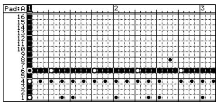
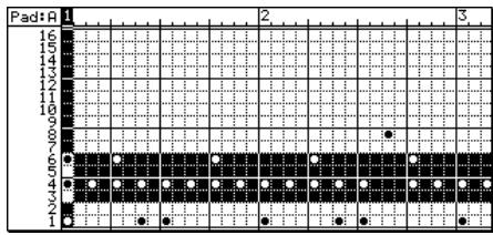
Hint: You can press the [F6] key (PLAY) to play back the selected region.
When you specify a region, the command assigned to the [F5] key (PASTE) will change to EDIT.
You can press the [WINDOW] key and use the event list (→ .34) to view just the note events of the selected region.
7. Use the [ERASE] key or the [F2] key (MOVE)-[F5] key (EDIT) to access the editing command that you want to use.
When you press one of these keys, a popup window for the corresponding editing command will appear.
The following commands are assigned to these keys.
- [ERASE] key: Erases the selected region.
- [F2] key (MOVE): Moves the selected region.
- [F3] key (COPY): Copies the selected region.
- [F4] key (CUT): Cuts the selected region.
- [F5] key (EDIT): Converts the velocities/durations of all note events in the selected region.
8. Execute the editing command.
For details on the procedure, refer to the next section.
About the editing commands
The following pages explain the editing commands assigned to the [ERASE] key and [F2] keys - [F4] keys in the sequence edit page.
[ERASE]key
This erases the selected region. When you press the key, the Erase popup window will appear.
![AKAI MPC4000 - [ERASE]key - 1](/content/2025/01/152367/images/8ae7510f3716b8f63bc529cdc584a0a857683c1de2643cade6c3a85048db2fbc.jpg)
① Track field: Displays the name of the track from which data will be erased.
② Time field: Displays the region of the time axis in which data will be erased.
③ Erase field: Displays the type of MIDI events that will be erased.
(4) Notes field: Displays the range of note numbers/pad numbers that will be erased.
(5) [F1] key (CANCEL): Cancels the Erase command and closes the popup window.
[6] [F6] key (DO IT): Executes the Erase command.
[F2] key (MOVE)
This command moves the selected region. When you press this key, the following fields will appear in the lower part of the display.
![AKAI MPC4000 - [F2] key (MOVE) - 1](/content/2025/01/152367/images/75f0f029402b499b59618aabd56cd5ba4f5432f4b65a30d4e1afbccfa0361d44.jpg)
① Move field: Indicates the direction in which the data will be moved. If this field is set to Time, the data can be moved along the time axis. If set to Note, the notes can be moved upward or downward. If the track is a drum-type track, this field can be set only to Time.
② From field: Indicates the current position of the MIDI event(s) that will be moved.
(3) to field: Specifies the location to which the data will be moved, in units of measures/beats/ticks.
④ Mode field: Selects whether any MIDI events existing in the move-destination region will be combined with the MIDI events that are moved (MERGE), or will be overwritten by them (REPLACE).
(5) [F1] key (CANCEL): Cancels the editing command and closes the popup window.
[6] [F2] key (DO IT): Moves the MIDI events.
Hint: You can use the [F3] key (-) and [F4] key (+) to make fine adjustments to the selected region in units of one tick.
[F3] key (COPY)
This command copies the MIDI events to the clipboard (an area of memory in which data is stored temporarily), or saves them as a library. If you press this key when a single grid is selected, the note event(s) in that grid will be copied to the clipboard. If you press this key when multiple grids are selected, the Copy Data popup window will appear.
![AKAI MPC4000 - [F3] key (COPY) - 1](/content/2025/01/152367/images/0638c39b4a2a76e7aa1d554a02b5c63d2b2e4baea0a85c3129692e6661de7375.jpg)
① Time field: Indicates the measure region that is currently selected.
(2) Notes field: Indicates the note event range that is currently selected.
③ New name field: Here you can input the library name that will be used if you save the copied region as a phrase library.
(4) [F1] key (CANCEL): Cancels the editing command and closes the popup window.
[5] [F5] key (LIBRARY): Saves the selected region as a phrase library.
[6] [F6] key (CLIP BD): Copies the selected region to the clipboard.
[F4] key (CUT)
This command cuts the MIDI events that are in the selected region. The MIDI events that are cut can be placed in the clipboard or saved as a phrase library. If you press this key when a single grid is selected, the note event(s) in that grid will be cut. If you press this key when multiple grids are selected, the Cut Data popup window will appear.
![AKAI MPC4000 - [F4] key (CUT) - 1](/content/2025/01/152367/images/ede0ef24308e994be3f00b32c68e0f9ec2dc541e4826604840fd26488f8a3d1f.jpg)
The fields in this popup window are the same as for the COPY command.
Hint: The [F4] key (CUT) copies the selected event(s) and then erases them. This means that you can also use this command to delete events.
[F5] key (EDIT)/(PASTE)
The editing command assigned to the [F5] key will depend on whether you have selected a region in the graphic editor. EDIT will be assigned to this key if you have selected a region, and PASTE if you have not selected a region.
- EDIT
This command converts the MIDI events in the selected region. If this command is assigned to the [F5] key, the Edit Multiple popup window will appear when you press the key.
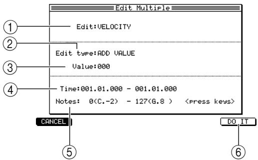
① Edit field: Here you can choose the element (velocity or duration) that will be modified. This field will be displayed only if you have selected note events.
② Edit type field: Here you can choose one of the following four ways in which to modify the value.
-
ADD VALUE: The setting of the Value field will be added to the current values.
-
SUB VALUE: The setting of the Value field will be subtracted from the current values.
- MULT VAL%: The current values will be multiplied by the setting of the Value field.
- SET TO VAL: The current values will all be replaced by the setting of the Value field.
③ Value field: Here you can input the value by which the adjustment will be made.
④ Time field: Indicates the time region you selected. You can edit these values to make fine adjustments to the selected region.
⑤ Notes field: Indicates the region of note numbers you selected. You can edit these values to adjust the selected range of pitches.
[6] [F6] key (DO IT): Executes the editing command.
PASTE
This command pastes the MIDI events that were copied or cut. If this command is assigned to the [F5] key, the Paste Data popup window will appear when you press the key.
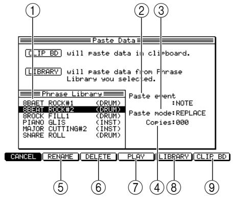
① Phrase Library field: This displays a list of the phrase libraries that have been stored in the MPC4000's flash ROM.
② Paste event field: Here you can choose the type of MIDI events that will be pasted. If you choose NOTE, only the note data included in the library will be pasted.
③ Paste mode field: Here you can choose how any MIDI events already existing in the destination will be handled: MERGE (the pasted data will be combined with the existing MIDI events) or REPLACE (the pasted data will overwrite the existing MIDI events).
④ Copies field: Specify the number of times the data will be copied.
(5) [F2] key (RENAME): Renames the selected phrase library.
(6) [F3] key (DELETE): Deletes the selected phrase library.
[4] key (PLAY): Plays the selected phrase library.
[8] [F5] key (LIBRARY): Pastes the selected phrase library into the location of the Now field.
[9] [F6] key (CLIP BD): Pastes the MIDI events that you cut/copied into the location of the Now field.
Editing an INST type track
You can use a piano-roll graphic editor to perform editing operations such as Copy or Delete on the note events recorded in an INST type track.
1. Select an INST type track in the main page, and press the [SEQ EDIT] key.
When you select an INST type track and press the [SEQ EDIT] key, the piano-roll graphic editor will appear.
![AKAI MPC4000 - Select an INST type track in the main page, and press the [SEQ EDIT] key. - 1](/content/2025/01/152367/images/cb0466cc08512877ca5dfdc6b792c871a95e15d7eac155d60ceafb81cac43e91.jpg)
① Track field: Selects the track that will be displayed in the graphic editor.
② Timing correct: Indicates the note value that will be the minimum unit for timing correction. The setting of this field also determines the resolution of the horizontal axis (time ruler) of the graphic editor.
③ Now field: Indicates the current location within the sequence in measures/beats/ticks.
④ Graphic editor: This area graphically displays the note events and continuously variable events, and lets you select the range that you want to edit.
⑤ Time ruler: This indicates the time axis of the track. The markings on the ruler will be the smallest units by which you can select a region.
⑥ Note numbers: This area indicates the note numbers of the note events recorded in the track.
⑦ Vertical marker: This indicates the current location. Use this to specify the editing region in the time ruler.
⑧ Horizontal marker: Use this to specify the range of note numbers that you want to edit.
⑨ Note event: Note events recorded in the track are displayed as bars. The length (left to right) of the bar indicates the duration of the note event.
Field: Here you can select the type of MIDI event that will be displayed in the graphic editor.
Hint: If the graphic editor does not show the piano-roll type display, change the View field to NOTE. You can use the TRACK field to select a different track for editing at any time.
2. To switch the range of notes shown in the graphic editor, move the cursor into the graphic editor and press the CURSOR [▲]/[▼] keys repeatedly to scroll the piano-roll upward or downward.
Hint: You can switch the displayed range of notes instantly by pressing the pad or note on your MIDI keyboard that corresponds to the note number you want to see.
3. Move the cursor to the Timing correct field, and specify the resolution of the time ruler.
Normally you should set the grid resolution to the smallest interval between the note events that you want to edit.
4. Move the cursor to the measure, beat, or tick of the Now field, and move the vertical marker to the beginning of the range that you want to edit.
If the cursor is located within the graphic editor, you can also use the CURSOR [▲]/[▶] keys or the [JOG] dial to move the vertical marker.
5. Use the BLOCK CURSOR [Δ] / [] keys to move the cursor into the graphic editor.
6. Select the note event that you want to edit.
- To select a single note
Press the pad or MIDI key for the note event you want to edit. The horizontal marker will move to that note number.
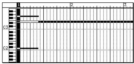
- To select multiple notes
Press the pad or MIDI key for one of the note events you want to edit. Then hold down the [SHIFT] key and use the CURSOR [] / [] / [] / [] keys to extend the selected range.
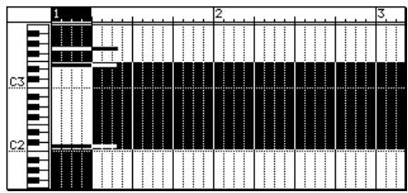
The region in which the vertical and horizontal markers intersect will be the selected region. All note events whose beginning (note-on) is included in this region will be selected for editing.
Hint: You can press the [F6] key (PLAY) to play back the selected region.
When you select a region, the function assigned to the [F5] key (PASTE) will change to EDIT.
If you press the [WINDOW] key, the note events included in the selected region will be displayed in the event list (→ p.34) .
7. Use the [ERASE] key or [F2] key (MOVE)-[F5] key (EDIT) to choose an editing command.
Refer to page 28 for the functions assigned to each key and details on operation.
Editing continuously-variable events
You can use the graphic editor to graphically view continuously-variable events such as control changes and pitch bend. Here we will explain how to use the graphic editor to view and edit continuously-variable events such as control change that have been recorded in a track.
1. In the main page, select the track that you want to edit, and press the [SEQ EDIT] key.
The Sequence Edit page will appear. Editing for continuously-variable events is the same for both DRUM type and INST type tracks. Regardless of which type of track you are editing, you can use the following procedure to edit continuously-variable events.
Hint: You can use the Track field to select a different track for editing at any time.
2. Move the cursor to the View field and turn the [JOG] dial to select the continuously-variable event that you want to edit.
In the graphic editor, use the View field to select the type of MIDI events you want to edit. If you select a continuously-variable event, the contents of this type of event will be displayed as a graph.
![AKAI MPC4000 - Move the cursor to the View field and turn the [JOG] dial to select the continuously-variable event that you want to edit. - 1](/content/2025/01/152367/images/5ac23d4af4c4440cb1d94c4e232754900cc88e3cd47664985286fb09cd9da2b9.jpg)
① Graph: This shows the continuously-variable event. The left/right direction is the time axis, and the up/down direction is the value of the continuously-variable event.
② Time ruler: This indicates the time axis of the track. The markings on this ruler will be the smallest units by which you can select a region.
(3) Continuously-variable event value: This area indicates the value of the continuously-variable event.
④ Marker: This indicates the current location. Use it to select the continuously-variable events you want to edit.
You can edit the following types of continuously-variable event.
PITCH BEND
- CONTROL CHANGE
- CH PRESSURE (Channel Key Pressure)
- POLY PRESSURE (Polyphonic Key Pressure)
If you select CONTROL CHANGE or POLY PRESSURE, a field will appear at the right, letting you specify the control change number or note number.
3. If you selected CONTROL CHANGE or POLY PRESSURE, press the CURSOR [▶] key to move the cursor, and turn the [JOG] dial to select the control change number or note number.
- Move the cursor to the Timing correct field, and turn the [JOG] dial to specify the resolution of the time ruler.
- Move the cursor to the Now field, and move the marker to the beginning of the area that you want to edit.
- Use the BLOCK CURSOR [Δ] / [] keys to move the cursor into the graph area.
You can use the CURSOR [] / [] keys to move the marker in steps of the units shown on the time ruler.
- Hold down the [SHIFT] key and press the CURSOR [▶] key to select the region that you want to edit.
- Press the [ERASE] key or [F2] key (MOVE)-[F5] key (EDIT) to select an editing command.
Refer to page 28 for the functions assigned to each key and details on operation.
Adding continuously-variable events
You can use the INSERT command to add continuously-variable events according to a curve that you specify. For example, this is a convenient way to create a fade-in/out at a specific point in a sequence.
- In the main window, select the track to which you want to add continuously-variable events, and press the [SEQ EDIT] key.
The Sequence Edit page will appear.
- Move the cursor to the View field, and turn the [JOG] dial to select the type of continuously-variable events that you want to add.
- If you selected CONTROL CHANGE or POLY PRESSURE, press the CURSOR [▶] key to move the cursor, and turn the [JOG] dial to select the control change number or note number.
- Move the cursor to the Timing correct field, and turn the [JOG] dial to specify the resolution of the time ruler.
- Move the cursor to the Now field, and move the marker to the location at which you want to start adding events.
- Use the BLOCK CURSOR [Δ] / [] keys to move the cursor into the graphic editor.
- Hold down the [SHIFT] key and press the CURSOR [▶] key to specify the region in which you will add continuously-variable events.
- Press the [OVER DUB] key.
In this state, you can add MIDI events to the track. The INSERT command will be assigned to the [F6] key.
- Press the [F6] key (INSERT).
The Insert Event popup window will appear. In this popup window, you can add the currently-displayed type of continuously-variable events according to a curve that you specify.
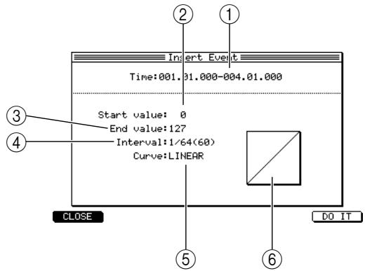
① Time field: Specifies the start and end locations (in measure/beat/tick units) of the continuously-variable events that will be added.
② Start value field: Specifies the value of the continuously-variable event at the start location.
③ End value field: Specifies the value of the continuously-variable event at the end location.
(4) Interval field: Specifies the spacing at which the continuously-variable events will be added.
⑤ Curve field: Specifies the curve of the events that will be added.
Curve graph: This area displays a graph showing the curve of the continuously-variable events that will be added. The left edge is the Start location, and the right edge is the End location.
Hint: If the graphic editor is displaying a matrix or piano-roll, you can use this popup window to add note events.
- Make sure that the Time field shows the start location and end location that you specified in step 7. If you specified a region before opening the Insert Event popup window, the start and end times of that region will automatically be input in the Time field. However, you are free to change these settings later.
Hint: If you want to input only a single continuously-variable event, set the start and end times to the same position and value.
- Move the cursor to the Start value field and turn the [JOG] dial to specify the starting value.
-
Move the cursor to the End value field and turn the [JOG] dial to specify the ending value.
-
If desired, move the cursor to the Interval field and turn the [JOG] dial to specify the spacing at which the continuously-variable events will be added.
You can set this field in a range of 1/4 (quarter note)-1 tick (1/960th of a quarter note). As you decrease the value of this setting, the continuously-variable events will change more smoothly.
- Move the cursor to the Curve field, and turn the [JOG] dial to select one of the following curves.
LINEAR
The value will change in a straight line from the start to the end points.
LOGARITHM
The value will change in a logarithmic curve from the start to the end points. In the case of an increasing value, the change will become greater as you approach the end point. In the case of a decreasing value, the change will become less as you approach the end point.
- EXPONENTIAL
The value will change exponentially from the start to the end points. In the case of an increasing value, the change will become less as you approach the end point. In the case of a decreasing value, the change will become greater as you approach the end point.



- To execute the command and add the continuously-variable events, press the [F6] key (DO IT).
Hint: Continuously-variable events can also be added in the Step Edit page (see the section that follows). Using the Event List to edit
Using the event list
The event list lets you view and edit the data values of individual MIDI events that are recorded in a track. This is convenient when you want to edit only a specific MIDI event, or when you want to make detailed adjustments to the value or timing of a MIDI event.
1. Press the [STEP EDIT] key.
The Step Edit page will appear. In this page you can use the event list to edit MIDI events.
![AKAI MPC4000 - Press the [STEP EDIT] key. - 1](/content/2025/01/152367/images/21e43c408fc23a80aa01c76e974fb7e2467a927951eec91a22f6d81056d20df8.jpg)
① Event list: The area at the far left (Time field) shows the location of the MIDI event in measures/beats/ticks. To its right, the list shows the type of event and data values. The fields other than the Time field will differ according to the type of MIDI event.
② View field: Here you can select the type of MIDI event(s) that will be displayed in the event list.
-
Use the BLOCK CURSOR [Δ] / [] keys to move the cursor into the event list.
-
Move the cursor to the Time field of the MIDI events, and turn the [JOG] dial to display the MIDI event that you want to edit.
When the cursor is in the Time field, you can turn the [JOG] dial to scroll the list.
- Press the CURSOR [▶] key to move the cursor to the MIDI event.
MIDI events will be displayed as follows.
Note events
Note number (pad number)/duration/velocity
:82/A34D:170U:110
- Continuously-variable events
Event type/control change number or note number (for control change/poly-pressure)
MIDI event type/continuously-variable event value (for other events)
![AKAI MPC4000 - Press the [STEP EDIT] key. - 2](/content/2025/01/152367/images/0acc70be93f9ed4e57f23da250f2936df63085df223b79e5357567ed8f97c709.jpg)
- System exclusive
Each byte of the message (hexadecimal)
:EXCLUSIVE:F0 00 00 00 00 00 00 00 00..
- Turn the [JOG] dial to edit the value of the MIDI event.
When editing a system exclusive, use the CURSOR [▶] key to move to each byte.
- If you want to edit the timing of an event, press the [F2] key (MOVE).
Use the to field to specify the move-destination location in measures/beats/ticks, and press the [F2] key (DO IT) to move the event to the specified location
- Repeat steps 3-6 to finish editing the track.
Hint: The event list also lets you specify a region and use commands such as copy and paste, just as in the graphic editor. To specify a region, move the cursor to the Time field, then hold down the [SHIFT] key and press the CURSOR [▲]/[▼] keys.
You can press the [OVER DUB] key to add note events or continuously-variable events (see page 25 for the procedure).
Copying a track
Here's how you can copy a track to another track within the sequence.
- Access the main page, and move the cursor to the Trk field.
- Press the [WINDOW] key.
The Track popup window will appear. In this popup window you can edit the track name or copy/delete individual tracks.
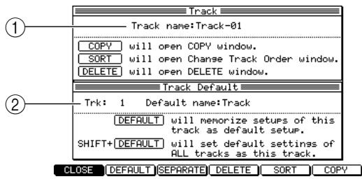
① Track name field: Edits the track name.
② Trk field: Edits the default name for tracks.
- Press the [F6] key (COPY).
The Copy Track popup window will appear.
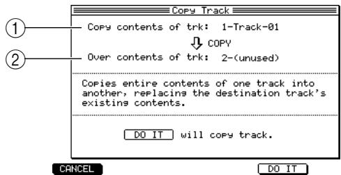
① Copy contents of Trk field: Selects the copy-source track.
Over contents of the Trk field: Selects the copy-destination track.
- Move the cursor to the Copy contents of Trk field, and turn the [JOG] dial to select the copy-source track.
- Move the cursor to the Over contents of Trk field, and turn the [JOG] dial to select an empty track.
Hint: A track in which MIDI events have already been recorded can also be selected as the copy-destination. In this case, the contents of the copy-destination track will be overwritten.
- To execute the copy command, press the [F6] key (DO IT).
Deleting a track
Here's how to delete a track from the sequence.
- Access the main window and move the cursor to the Trk field.
- Press the [WINDOW] key.
The Track popup window will appear.
- Press the [F4] key (DELETE).
The Delete Track popup window will appear.
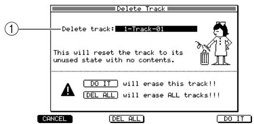
① Delete track field: Selects the track to be deleted.
- Move the cursor to the Delete track field, and turn the [JOG] dial to select the track that you want to delete.
- To execute the delete command, press the [F6] key (DO IT).
The specified track will be deleted, becoming an empty track. The track name will revert to "Unused.")
Editing a sequence
The following pages explain how to perform editing operations that apply to an entire sequence, such as copying or deleting a sequence.
Copying a sequence
Here's how to copy a sequence in the memory of the MPC4000 to an empty sequence.
- Access the main window, and move the cursor to the Seq field.
- Press the [WINDOW] key.
The Sequence popup window will appear. In this popup window you can edit the sequence name, or copy/delete a sequence.
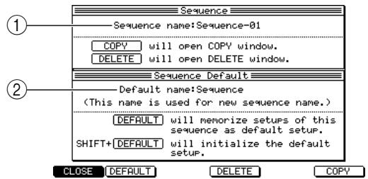
① Sequence name field: Edits the sequence name.
② Default name field: Edits the default name for sequences.
- Press the [F6] key (COPY).
The Copy Sequence popup window will appear.
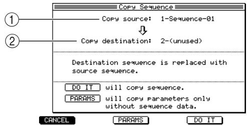
① Copy source field: Selects the copy-source sequence.
② Copy destination field: Selects the copy-destination sequence.
- Move the cursor to the Copy source field, and turn the [JOG] dial to select the copy-source sequence.
- Move the cursor to the Copy destination field, and turn the [JOG] dial to select the copy-destination sequence.
Hint: A sequence in which MIDI events have already been recorded can also be selected as the copy-destination. In this case, the copy-destination sequence will be overwritten by the copy-source sequence.
- To execute the copy command, press the [F5] key (DO IT).
Hint: If you press the [F3] key (PARAMS) instead of the [F5] key (DO IT), only settings such as the sequence name and track parameters will be copied, and the MIDI events will not be copied. This is useful when you want to create two or more sequences with the same settings.
Deleting a sequence
Here's how to delete a sequence in the memory of the MPC4000.
- Access the main window, and move the cursor to the Seq field.
- Press the [WINDOW] key.
The Sequence popup window will appear.
- Press the [F4] key (DELETE).
The Delete Sequence popup window will appear.
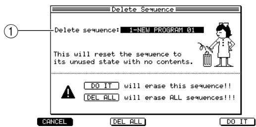
Delete sequence field: Selects the sequence that will be deleted.
- Move the cursor to the Delete Sequence field, and turn the [JOG] dial to select the sequence you want to delete.
- To execute the Delete command, press the [F6] key (DO IT).
The corresponding sequence will be deleted, and will become empty. The sequence name will revert to "x-(Unused)" (x will be a sequence number 1-128).
Hint: If you press the [F3] key (DEL ALL) instead of the [F6] key (DO IT), the Delete ALL Sequences popup window will appear, allowing you to delete all sequences from the memory of the MPC4000.
Viewing the parameters of all tracks
You can view a list of all tracks in the sequence, to see the output destination selection and mute on/off status of each track. You can also move the cursor to the various parameters that are displayed and edit their settings.
- Access the main page and select the sequence whose parameters you want to view.
- Press the [F2] key (TR LIST).
The first time you press the [F2] key after starting up the MPC4000, the Out1 page will appear, listing the Out1 field settings for each track.
- As necessary, press the [F2] key (OUT 1)-(F4] key (PARAMS) to view the parameters that you want to edit.
The track list is divided by parameter into three pages.
- Out1 page
For each track, this displays the Out1 field setting (output destination setting, part number or MIDI channel setting), the track type, and mute on/off.
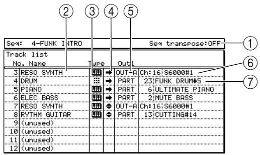
① Seq transpose field: Indicates the transpose setting that will be applied to all INST type tracks in the sequence.
② No./Name field: Indicates the track number and track name.
③ Type field: Indicates the type of each track. DRUM type tracks are indicated by the symbol, and INST type tracks are indicated by the symbol.
④ Mute field: Indicates the mute on/off status of each track. The symbol indicates off, and the symbol indicates on.
⑤ Out1 field: Indicates the setting of the Out1 field for each track.
⑥ Chfield/Device field: Indicates the MIDI channel and device name to which each track is being output. This field will be displayed if OUT A-OUT D/INT-A/INT-B are selected as the output destination.
⑦ Part number/program field: Indicates the part number and program name to which each track is being output. This field will be displayed if PART is selected as the output destination.
Out2 page
For each track, this displays the Out2 field setting (output destination setting, part number or MIDI channel setting), the track type, and mute on/off.
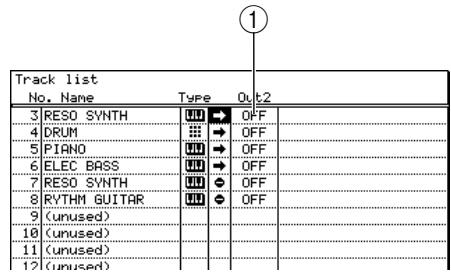
① Out2 field: Indicates the setting of the Out2 field for each track.
Ch: The field/device field and part number/program field are the same as for Out1.
- PARAMS page
This page displays the program change number, transpose, duration/velocity offset value, and effect send level for each track.
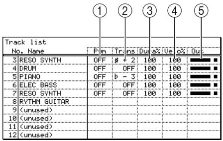
① Pgm field: Indicates the program change number that will be transmitted when you play back the sequence.
② Trans field: Indicates the transposition setting for each track.
(3) Dura% field: Indicates the duration offset value as a percentage.
④ Velo%: Indicates the velocity offset value as a percentage.
⑤ Out field: Indicates the MIDI event output status of the track.
-
Move the cursor to the No./Name field of the desired page, and turn the [JOG] dial to select the track whose settings you want to edit.
-
Repeatedly press the CURSOR [▶] key to select the parameter you want to edit.
Hint: You can use the CURSOR [▲]/[▼]/[▲]/[▲] keys to move the cursor directly to a field.
- Turn the [JOG] dial to change the setting.
The setting will take effect as soon as you change it. As necessary, repeat steps 3-5 to edit the settings for other items or other tracks.
Saving and loading a sequence
This section explains how you can save a sequence from memory to an internal or external storage device, or load an existing sequence from a storage device into memory.
Saving all sequences/songs
Here's how to save all sequences/songs from the internal memory of the MPC4000 to a storage device. This method lets you back up all data of the sequencer section as a single file (an ALL file).
- Press the [SAVE] key.
The Save page will appear. In this page you can store data from internal memory to a storage device. Use the Type field to specify the type of data that you want to save.
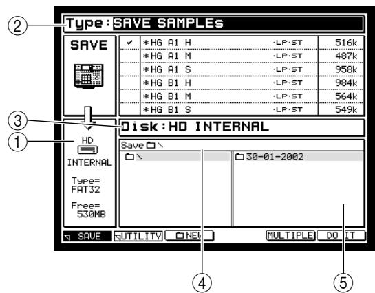
① Disk information: Indicates the storage device that is currently selected for the operation.
② Type field: Selects the type of data that will be saved.
③ Disk field: Selects the destination storage device.
Save to field: Indicates the folder within the destination storage device.
⑤ File list block: Displays the folder hierarchy within the selected storage device.
- Move the cursor to the Type field and turn the [JOG] dial to select SAVE ALL SEQs AND SONGs. The list within the page will change as follows.
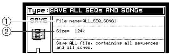
① File name field: Specifies a name for the file that will be saved.
② Size field: Indicates the size of the file that will be saved.
- Move the cursor to the File name field, and specify a name for the file.
- Move the cursor to the Disk field, and turn the [JOG] dial to access the Disk List popup window. In this popup window you can select the destination storage device.
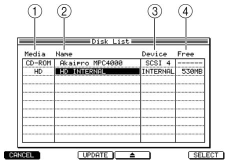
① Media field: Indicates the type of storage device.
② Name field: Indicates the volume name of the storage device.
③ Device field: Indicates how the storage device is connected.
④ Free field: Indicates the free capacity of the storage device.
- Move the cursor to the storage device to which you want to save the data, and press the [F6] key (SELECT).
The corresponding storage device will be selected, and the popup window will close.
- Move the cursor to the folder in the file list block to which you want to save the data.
Use the CURSOR [] / [] keys to move up or down between levels, and use the CURSOR [] / [] keys to select different folders within the same level. When you select the save-destination folder, the name of that folder will appear in the Save field.
Hint: You can press the [F3] key (NEW) to create a new folder at the current level. The saved files will be saved within the folder you selected at the left of the file list (the level that is shown in the right).
- To execute the Save operation, press the [F6] key (DO IT).
The data will be saved as an ALL file in the folder you selected.
If a file of the same name already exists in the save-destination folder, a FileExists popup window will appear when you press the [F6] key. If this occurs, you can either press the [F3] key (RENAME) to change the name of the file, or press the [F5] key (REPLACE) to save the data and overwrite the existing file.
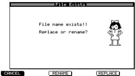
A saved All file will be indicated by an ALL icon in the file list block of the Load page.
Saving a single sequence
Here's how to save a single sequence from the memory of the MPC4000 to a storage device.
1. Press the [SAVE] key.
The Save page will appear.
2. Move the cursor to the Type field, and turn the [JOG] dial to select SAVE SEQUENCE.
When you select SAVE SEQUENCE, the following parts of the display will change.
![AKAI MPC4000 - Move the cursor to the Type field, and turn the [JOG] dial to select SAVE SEQUENCE. - 1](/content/2025/01/152367/images/029c48c5a7e479d85d1fc9805cac47a8842e3f7fa1151df931e2d5c73a8a00ed.jpg)
① Data list: Shows the data in the internal memory of the MPC4000.
② MIDI file type field: Selects the type of sequence to be saved.
③ Size field: Indicates the size of the data you selected in the data list.
- Move the cursor to the Disk field and turn the [JOG] dial to access the Disk List popup window.
- Move the cursor to the storage device on which you want to save the data, and press the [F6] key (SELECT).
The save-destination device will be selected, and the popup window will close.
- Move the cursor into the data list, and use the CURSOR [Δ] /[▼] keys to move the cursor to the sequence that you want to save.
The sequence to which you move the cursor will be selected for saving. An asterisk * will be displayed at the beginning of the sequence name for any sequences whose contents have been modified after they were last saved or loaded.
Hint: When the cursor is in the data list, you can also select a sequence by turning the [JOG] dial.
- Move the cursor to the desired save-destination folder in the file list block.
Use the CURSOR [] / [] keys to move upward or downward between levels, and use the CURSOR
[Δ] / [] keys to select a different folder in the same level. When you select a save-destination folder, that folder name will appear in the Save field.
Hint: You can press the [F3] key (NEW) to create a new folder in the current level.
- To save the sequence, press the [F6] key (DO IT).
The single sequence will be saved in the specified folder. A saved sequence file will be indicated by an icon in the file list block of the Load page.
If a file of the same name already exists in the save-destination folder, a FileExists popup window will appear when you press the [F6] key. If this occurs, you can either press the [F3] key (RENAME) and rename the file, or press the [F5] key (REPLACE) to overwrite the existing file.
Loading an ALL file (all sequences/songs) or a single sequence
Here's how you can load a previously-saved file (a single sequence, or all sequences/songs) from a storage device into the memory of the MPC4000.
Note: When you load a single sequence or all sequences/songs, the newly loaded data will overwrite the sequence(s) or songs that were in memory. Please use this operation with care.
1. Press the [LOAD] key.
The Load page will appear. In this page you can load files that were saved on a storage device.
![AKAI MPC4000 - Press the [LOAD] key. - 1](/content/2025/01/152367/images/8e44e64293267eb26d09fce9bf8d130d8e585359d45c0efba1df0920d7c95b87.jpg)
① Disk information: Indicates the storage device that you have selected for operations.
② Disk field: Selects the load-source storage device.
③ File list block: Displays the hierarchy of the contents of the storage device you selected.
④ View field: Selects the type of file that will be displayed in the file list block.
⑤ Wave free field: Indicates the amount of free memory within the MPC4000's sampler section.
⑥Sequence free field: Indicates the amount of free memory within the MPC4000's sequencer section.
⑦ CPU free field: Indicates the amount of free memory within the MPC4000's data management area.
- Move the cursor to the Disk field, and turn the [JOG] dial to access the Disk List popup window.
- Move the cursor to the storage device from which you want to load data, and press the [F6] key (SELECT).
The storage device at which the cursor is located will be selected as the load-source storage device.
- Move the cursor to the View field, and turn the [JOG] dial to select the type of file that you want to load.
When you use the View field to select the type of file that you want to load, all other files will be hidden.
- Move the cursor to a file in the file list block.
Use the CURSOR [] / [] keys to move upward or downward between levels, and use the CURSOR [] / [] keys to select a folder or file in the same level.
- The following procedure will depend on the type of file you selected.
If loading a single sequence
- Press the [F6] key (DO IT) to access the Load a Sequence popup window.
- Move the cursor to the sequence list, and turn the [JOG] dial to select the sequence number into which you will load the sequence.
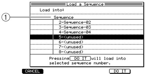
① Sequence list: Selects the sequence number into which the sequence will be loaded.
If loading an ALL (all sequences + songs) file
Press the [F6] key (DO IT) to access the Load ALL (songs and sequences) File popup window. When you load an ALL file, all sequence and song data in the memory of the MPC4000 will be overwritten. If internal memory contains data that you want to keep, save it to a storage device beforehand.
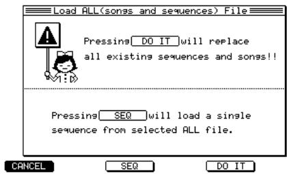
If loading a specific single sequence from within an ALL file
-
Press the [F6] key (DO IT), and then press the [F3] key (SEQ) to access the Load a Sequence popup window.
-
Move the cursor to the Seq field, and turn the [JOG] dial to select the desired sequence that you want to load from within the ALL file.
- Move the cursor to the sequence list, and select the sequence number into which the sequence will be loaded.
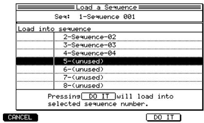
7. To execute the load operation, press the [F5] key.
When the data has been loaded, the contents of internal memory will be replaced by the contents of the file that was loaded.
Hint: If there is not enough free internal memory remaining, it may not be possible to load the selected file. In this case, delete unneeded data from memory to increase the free space, and try the operation again.
4 Creating and editing a song
This chapter explains how to perform Song mode operations such as creating and editing a song.
About songs
A "song" consists of multiple sequences arranged in the order of playback. The MPC4000 lets you use 128 songs. Immediately after the power is turned on, all songs are blank. In order to use a song, you must choose one of these songs in which to perform your song-editing operations.
To place sequences in a song, you will select a sequence for each step and specify the number of times that the sequence will be repeated. A song can consist of up to 250 steps, as memory permits.
Note: The steps in a song contain only sequence numbers; not MIDI events. This means that if you a sequence after you have registered it in a song, your changes will affect all steps that play that sequence.
In the same way as sequences, songs are kept in the internal memory of the MPC4000. If you turn off the power, all songs in memory will be lost. If you want to keep a song you created, you must save all sequences and songs from memory to an external storage device. (Refer to p.38 for details of this procedure.)
Hint: A song you create can be converted into a sequence (→ p.46) .
Creating a song
Here's how you can arrange the sequences in memory into the desired playback order to create a new song.
- Create or load sequences so that the sequences you want to use in your song are in internal memory.
- Press the [SONG] key.
The Song page will appear. In this page you can create, edit, or play songs.
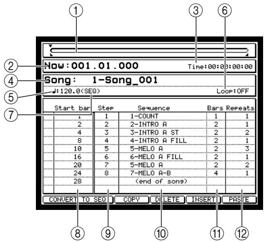
① Position bar: Indicates the current location of the currently-playing sequence.
② Now field: Indicates the current location of the song in measures/beats/ticks.
③ Time field: Indicates the current location of the song in hours/minutes/seconds/millisecond.
④ Song field: Selects the song that will be edited or played.
⑤ Tempo field: Indicates/sets the tempo of the song.
⑥ Loop field: Turns looping on/off for the song.
⑦ SEQ/MAS field: Selects the tempo source for the song; either SEQ (the fixed tempo that is programmed within each sequence) or MAS (a common tempo for all sequences).
⑧ Start bar field: Indicates the starting location of that step in terms of measure numbers in the song.
⑨ Step field: Indicates the step number.
⑩ Sequence field: Selects the sequence that will be played at this step.
① Bars field: Indicates the length of the sequence that is selected for this step, in terms of a number of measures. (Repeated measures are not included in this number.)
12 Repeats field: Specifies the number of times that the sequence will be repeated.
- Move the cursor to the Song field and turn the [JOG] dial to select the song that you want to create.
Immediately after the power is turned on, all songs will be empty. Empty songs are shown as "Unused.")
- Move the cursor to " (end of song)" in the Sequence field, and turn the [JOG] dial to select the sequence that you want to play at the beginning of the song.
When you select a sequence, the “(end of song)” indication that shows the end of the song will move to the next step.
When you modify the contents of a song, a song name of "Song_xxx" (x will be a song number 001-128) will be assigned automatically.
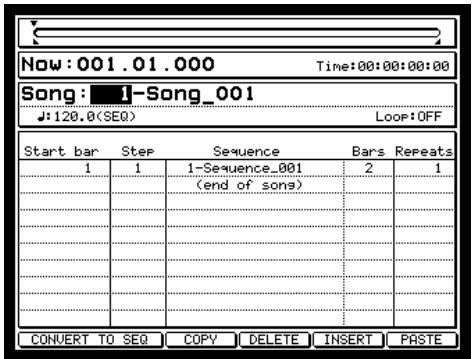
- If you want the sequence you assigned in step 4 to be repeated, move the cursor to the Repeat field and turn the [JOG] dial to specify the number of repeats.
Hint: You can also set the Repeats field to HOLD. In this case, that sequence will continue repeating until you press the [F6] key (NEXT) during playback.
- Move the cursor to " (end of song)" in the Sequence field, and turn the [JOG] dial to select the next sequence.
The Start bar field will indicate the starting location of the next sequence.
- Repeat steps 4-6 to finish registering sequences in the song.
- If you want to edit your settings, select that step, move the cursor to the desired field, and turn the [JOG] dial to edit the setting.
You are free to change the settings of each step in the song at a later time.
Hint: You can also use editing operations to copy, delete, or insert steps (→ p.45) .
- If you want all sequences to play back at a common tempo, move the cursor to the SEQ/MAS field and turn the [JOG] dial to change the setting to MAS.
If the SEQ / MAS field is set to MAS, all sequences in the song will play at the tempo shown in the tempo field.
Hint: You can also use the [MASTER TEMPO] key to switch the SEQ/MAS field.
If you press the [WINDOW] key when the cursor is in the tempo field, the Tempo/Fix Tempo popup window will appear. For details on this window, refer to the PDF reference manual.
- When you are ready to play the song, press the [PLAY] key.
Normally you will play songs only in Song mode. You can play, stop, or locate a song in the same way as in Sequence mode.
During playback, the function key assignments will change as follows.
- [F4] key (SUDDEN). When you press this key, the playback will jump immediately to the next step even if you were in the middle of a step.
- [F6] key (NEXT)......When you press this key, the playback will continue from the next step when the currently-playing sequence reaches the end, even if there were repeats still to be played.
Editing a song
Here's how you can copy, paste, insert, or delete steps within a song.
- In the Song page, move the cursor to the Song field and turn the [JOG] dial to select the song that you want to edit.
- In the Sequence field, move the cursor to the step that you want to edit.
If you copy or delete a step, the step you select here will be the step that is copied or deleted. If you insert or paste a step, the step will be inserted or pasted at the location of the step you select here.
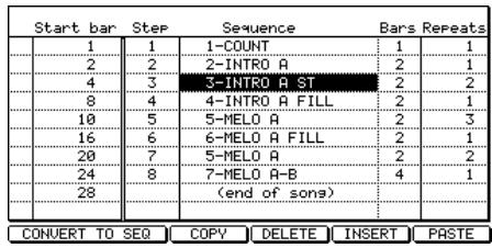
Hint: You can hold down the [SHIFT] key and use the CURSOR [Δ] / [] keys to select multiple adjacent steps.
-
Use the [F3] key (COPY)-[F6] key (PASTE) to execute the desired editing operation. Each key has the following function.
-
[F3] key (COPY).Copies the selected step to the clipboard (a memory area in which data is temporarily kept).
- [F4] key (DELETE)...... Deleted the selected step. Subsequent steps will move forward.
- [F5] key (INSERT) ........ Inserts the contents of the selected step at the selected step. The selected step and subsequent steps will move backward.
- [F6] key (PASTE) .......... Inserts the contents of the clipboard at the selected step. The selected step and subsequent steps will move backward. If the clipboard is empty, pressing this key will do nothing.
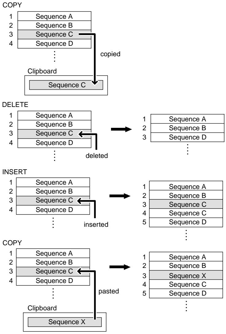
Deleting a song
Here's how to delete a song from internal memory, returning it to an empty state.
- Press the [SONG] key.
The Song page will appear.
- Move the cursor to the Song field, and turn the [JOG] dial to select the song that you want to delete.
We recommend that you play back the song to make sure that it really is the song you intend to delete.
- With the cursor located at the Song field, press the [WINDOW] key.
The Song/Song Default field will appear.
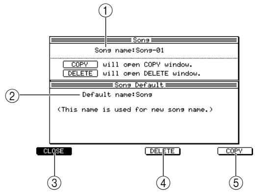
① Song name field: Displays/ edits the name of the currently selected song.
② Default name field: Displays the song name that will be assigned automatically when you create a song.
③ [F1] key (CLOSE): Closes the popup window.
(4) [F4] key (DELETE): Displays the Delete Song popup window, where you can delete a song.
(5) [F6] key (COPY): Displays the Copy Song lookup window, where you can copy the selected song. (For details, refer to the reference manual.)
- Press the [F4] key (DELETE).
The Delete Song popup window will appear.
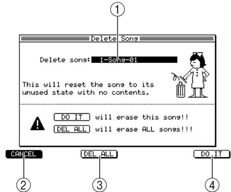
① Delete song field: Indicates/selects the song that will be deleted.
(2) [F1] key (CANCEL): Cancels the operation and returns to step 3.
(3) [F3] key (DEL ALL): Displays the Delete ALL Song popup window, where you can delete all songs from internal memory.
(4) [F6] key (DO IT): Executes the delete command.
- Make sure that the song you want to delete is selected in the Delete song field.
If the song you want to delete is not selected, move the cursor to the Delete song field and turn the [JOG] dial to select the song.
- To execute the delete command, press the [F6] key (DO IT).
When the song has been deleted, the window will close automatically.
Converting a song into a sequence
You can convert a completed song into a sequence. This is convenient when you want to add MIDI events to a song or to edit some of the MIDI events, or when you want to save a completed song as a single file.
- Press the [SONG] key.
The Song page will appear.
- Move the cursor to the Song field, and turn the [JOG] dial to select the song that you want to convert into a sequence.
We recommend that you play back the song to make sure that it is the one you want.
- Press the [F1] key or [F2] key (CONVERT TO SEQ).
The Convert Song to Seq popup window will appear. This popup window lets you convert a song into a sequence.
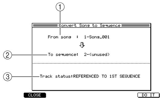
① From song field: Selects the song that will be converted.
② To sequence field: Selects the destination for the converted sequence.
③ Track status field: Selects how settings will be made for the tracks within the converted sequence.
- Make sure that the song you want to convert into a sequence is selected in the From song field. If not, turn the [JOG] dial to select the desired song.
- Move the cursor to the To sequence field, and turn the [JOG] dial to select the sequence that will be the destination for the converted sequence.
When the popup window appears, the lowest-numbered empty sequence will automatically be selected.
Note: If a sequence that already contains events is selected as the destination sequence, that sequence will be overwritten when you execute the Convert command. Be careful not to erase an important sequence by mistake.
-
Move the cursor to the Track status field, and turn the [JOG] dial to select one of the following ways in which track settings will be made for the tracks of the converted sequence.
-
REFERENCE TO 1ST SQ
The song will be converted into a sequence according to the track parameters and tempo of the sequence that is selected in the first step. Muted tracks will also be converted without change.
OFF TRACKS Ignored
With the exception that currently-muted tracks will not be converted, this is the same as REFERENCED TO 1ST SQ.
- MERGED ON MIDI CHANNEL
With the exception that tracks set to the same MIDI channel in each sequence will be combined into one track, this is the same as REFERENCED TO 1ST SQ.
- To execute the conversion, press the [F6] key (DO IT).
When the conversion is finished, the window will close automatically.
Note: It will not be possible to execute the song conversion if the result would contain more than 50,000 note events.
5 Using multis and parts
This chapter explains how to use "parts" which are the way you play the programs of the sampler section, and "multis" which let you manage multiple parts together.
About parts
In order to play a program that has been loaded into the sampler section, you must assign that program to a Part. You can think of a "part" as being the settings that a program need in order to play back; e.g., volume, pan, and output jack assignments.
On the MPC4000 you can use up to 128 parts. You can select a program and set parameters for each part, and use a sequencer or MIDI controller to play multiple parts simultaneously.
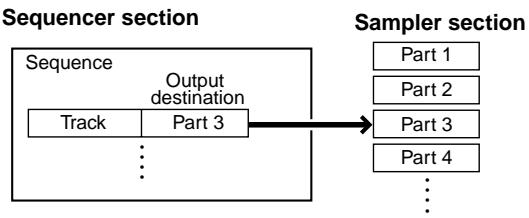
A part includes the following parameters.
Program
Output position of the signal sent to the effect bus
Volume
- Receive MIDI port/MIDI channel
Pan
- Pitch
Output destination audio jack
Note priority order
- Effect bus that will be used
- Program change number
- Effect bus send level
Key span (the range of the program)
There are two ways in which you can play a part from the internal sequencer.
(1) Specify the part directly
In this method you directly specify the output destination of a track as a specific part. If you use this method, you do not need to be aware of the receive MIDI port/MIDI channel of the part.
(2) Specify the part via the receive MIDI port/MIDI channel
In this method you set a receive MIDI port and MIDI channel for the part, and specify the same MIDI port and MIDI channel as the output destination of the track. This method lets you play multiple parts together from one MIDI channel.
About multis
Settings for up to 128 parts together with settings for the internal effects (the effect type and effect routing to be used) are collectively called a "multi."
All multi and part settings are maintained in memory. When you turn off the power of the MPC4000, all multis, parts, and effect settings in memory will be lost. If you want to keep your part and multi settings, you must save the multi to a storage device before you turn off the power. (For details on how to save, refer to → p.54) If all part settings and internal effect settings you use in a song are saved as a multi, you will be able to instantly recall these settings whenever you need to.
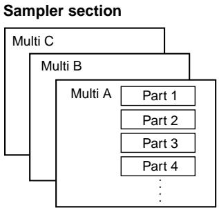
Editing part parameters
The following pages explain how to select the program that will be used by each part, and set parameters such as volume, receive MIDI port and MIDI channel.
Assigning a program to a part
Here's how you can assign a program from the MPC4000's internal memory to each part of the currently selected multi.
1. Press the [MULTI] key, and then press the [F2] key (MIX).
The Mix page will appear. In this page you can edit mix-related parameters for each part.
![AKAI MPC4000 - Press the [MULTI] key, and then press the [F2] key (MIX). - 1](/content/2025/01/152367/images/89727c4ea15242b9045db28d2d283bb45d46e066d8f5653144ecb78754f9d597.jpg)
① Multi field: Indicates the name of the currently selected multi.
② Part field: Indicates the part number.
③ Program/Type field: Selects the program that will be assigned to that part. The Type field will show an abbreviation to indicate the type of program that is selected.
④ Lvl field: Adjusts the volume of that part.
⑤ Pan field: Adjusts the pan of that part.
⑥ Out field: Specifies the output jack for the audio signal of that part.
⑦ FX field: Adjusts the send level to the effect bus you selected in ⑧.
⑧ Send field: Selects the effect bus that will be used by that part.
(9) [F5] key (MUTE): Mutes the part that is currently selected by the cursor.
[10] [F6] key (SOLO): Solos the part that is currently selected by the cursor (all other parts will be muted).
2. If necessary, move the cursor to the Multi field and turn the [JOG] dial to select a multi.
Hint: You can also switch multis in the List page ([MULTI] key → [F1] key).
3. Move the cursor to the Part field, and turn the [JOG] dial to select the part whose parameters you want to edit.
4. Move the cursor to the Program/Type field of the part to which you want to assign a program, and turn the [JOG] dial to assign the desired program.
The program Type area at the right of the program name will show an abbreviation indicating the type of program you assigned (DR=drum program, KG=key group program).
Hint: You can also assign a program in the MIDI page ([MULTI] key → [F3] key), Span page ([MULTI] key → [F4] key), or Main page ([MAIN] key).
Adjusting the mix parameters of a part
Here's how to adjust the mix parameters such as volume, pan, and effect send level for each part.
1. Press the [MULTI] key, and then press the [F2] key (MIX).
2. Move the cursor to the Part field and turn the [JOG] dial to select the part whose settings you want to adjust.
| Part Program | Type |
| 1 Drum set | DR |
| 2 Sonth BASS 06 | KS |
| 3 Soft Piano | KS |
| 4 Power Brass | KS |
| 5 Japanese Perc | DR |
| 6 Drum Loop#03 | DR |
3. Move the cursor to the field of the parameter you want to adjust, and turn the [JOG] dial to adjust the value.
The setting of the parameter will change immediately when you adjust it. Each parameter has the following range.
Lvl (volume) field. 60.00 dB+6.0 dB
Pan field. L50-MID (center)-R50
- Out (output destination) field ......... L/R ([MAIN OUT] jacks), 1-8 (optional individual outputs), 1/2, 3/4, 5/6, 7/8, L, R
- FX (effect bus) field. A-D, AB, CD, OFF (no signal will be sent)
- Send field. -40.00 dB+6.00 dB
Hint: The Pan parameter is valid only if you have selected L/R, 1/2, 3/4, 5/6, or 7/8 as the output destination. By setting the FX parameter to A/B or C/D, you can use the effects of effect buses AB or CD as stereo-in/stereo-out.
Setting the receive MIDI port/MIDI channel of a part
Here's how to set the receive MIDI port and MIDI channel of a part so that you can play that part from a track of the sequencer section via a virtual MIDI port (INT-A/INT-B).
1. Press the [MULTI] key, and then press the [F3] key (MIDI).
The MIDI page will appear. In this page you can specify the receive MIDI channel for each part. Here you can also select the program that will be assigned to each part, and specify the priority in which each part will sound.
![AKAI MPC4000 - Press the [MULTI] key, and then press the [F3] key (MIDI). - 1](/content/2025/01/152367/images/fb3d785d7caae9dde81da8de8b9ee1e90c16d6d8d4c8196746bf7ed94c91f8f2.jpg)
① Multi field: Indicates the name of the currently selected multi.
② Part field: Indicates the part numbers.
③ Program/Type field: Selects the program that will be assigned to the part. The Type field shows an abbreviation to indicate the program type.
④ MIDI Ch field: Specifies the receive MIDI channel/receive MIDI port for the part.
⑤ Tune field: Adjusts the pitch of the part.
(6) Priority field: Specifies the priority given to the part for playing notes.
⑦ Prog No. field: Specifies the program change number of the program that is selected for the part.
2. Move the cursor to the Part field, and turn the [JOG] dial to select a part.
3. Move the cursor to the parameter field that you want to adjust, and turn the [JOG] dial to adjust the value.
The available settings for each parameter are as follows.
- MIDI Ch field. 1A-16A, 1B-16B
Tune field. 36.00+36.00 semitones - Priority field............HOLD/HIGH/NORMAL/LOW
Prog No. field .OFF, 1-128
Hint: The setting of the Priority field represents a priority in the descending order of HOLD → HIGH → NORMAL → LOW . If the MPC4000 runs out of voices, it will turn off currently-sounding notes in the priority order you specify here. If you set a part to HOLD , its program will never be turned off.
Adjusting the note range of a part
By specifying the highest and lowest note that a part will play, you can limit a part to sounding only in a specific range of notes.
1. Press the [MULTI] key, and then press the [F4] key (SPAN).
The Multi mode Span page will appear.
![AKAI MPC4000 - Press the [MULTI] key, and then press the [F4] key (SPAN). - 1](/content/2025/01/152367/images/b409827897d5cdad1486b320cb30152b6b3a284b64b6cb44352d8ac7010cc58b.jpg)
① Multi field: Indicates the name of the currently selected multi.
② Part field: Indicates the part numbers.
③ Program/Type field: Selects the program that will be assigned to the part. The Type field shows an abbreviation to indicate the program type.
④ Low field: Specifies the note number that will be the lowest note sounded by the part.
⑤ Hi field: Specifies the note number that will be the highest note sounded by the part.
⑥ Keyboard: Graphically indicates the note range of the part.
- Move the cursor to the Part field, and turn the [JOG] dial to select a part.
- Move the cursor to the Low field of the part, and turn the [JOG] dial to specify the note number that will be the lowest note for that part.
- Move the cursor to the Hi field of the part, and turn the [JOG] dial to specify the note number that will be the highest note for that part.
The note numbers between the Low and Hi settings will be the range for that part.
Adding or deleting a part
Here's how to add a part to a multi, or delete a part from a multi.
- Press the [MULTI] key, and then press the [F2] key (MIX).
The Mix page will appear.
- Move the cursor to the Part field, and press the [WINDOW] key.
The Part popup window will appear. In this window you can add a part to the currently selected multi, or delete a part from the multi.
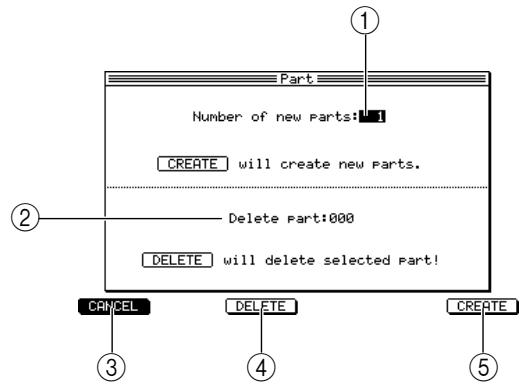
① Number of new parts field: Specifies the number of parts that will be added.
② Delete part field: Selects the part number that will be deleted.
(3) [F1] key (CANCEL): Cancels the operation and closes the popup window.
④ [F3] key (DELETE): Deletes the selected part.
(5) [F6] key (CREATE): Creates the specified number of new parts.
- If you want to add one or more parts, turn the [JOG] dial in the Number of new parts field to specify the number of parts that will be added, and then press the [F6] key (CREATE).
The parts will be added, and you will return to the state of step 1.
Note: A multi can have a maximum of 128 parts. It is not possible to add parts to a multi to make it contain more than 128 parts.
- If you want to delete a certain part, turn the [JOG] dial in the Delete part field to specify the part number to be deleted, and press the [F5] key (DELETE).
The part will be deleted, and you will return to the state of step 1.
Creating a multi
Here's how to create a new multi. When you create a multi, you are free to specify the number of parts.
- Press the [MULTI] key.
The Multi mode List page will appear. This page lists the multis that are in internal memory.
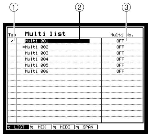
Hint: An asterisk * will be added before the name of multis whose contents you modified after saving or loading them.
You can also switch multis by sending program changes to the MPC4000. (For details, refer to the PDF reference manual.)
2. Move the cursor to the Multi list, and press the [WINDOW] key.
The Multi popup window will appear.
![AKAI MPC4000 - Move the cursor to the Multi list, and press the [WINDOW] key. - 1](/content/2025/01/152367/images/d092ce3144d15d17a1196507efe53294b3b3939f70ed90cc2d47e9a72d343ac0.jpg)
3. Press the [F5] key (NEW).
The Create New Multi popup window will appear.
![AKAI MPC4000 - Press the [F5] key (NEW). - 1](/content/2025/01/152367/images/924469971eb68d744080e26446776dcb5f9966c7a4d1c8c48728aa97ff0c8e7d.jpg)
4. Move the cursor to the New Name field, and use the [JOG] dial to assign a name to the newly created multi.
Refer to page 13 for details on how to input characters.
5. Move the cursor to the Number of parts field, and turn the [JOG] dial to specify the number of parts that you want to use in the new multi.
You are free to change this setting later.
6. To execute, press the [F6] key (DO IT).
The new multi will be created, and the popup window will close.
7. In order to use the multi you created, move the cursor to that multi.
The new multi will be selected.
Hint: You can also switch multis in the Multi field that appears in the Mix page, MIDI page, or Span page.
Copying a multi
Here's how to copy a multi within the internal memory of the MPC4000.
- Press the [MULTI] key. The list page will appear.
- Move the cursor to the multi list, and press the [WINDOW] key. The Multi popup window will appear.
- Press the [F6] key (COPY). The Copy Multi popup window will appear.
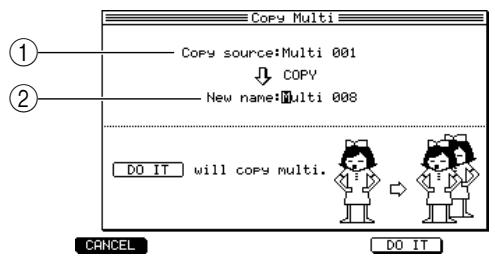
① Copy Source field: Selects the copy-source multi.
② New name field: Specifies a name for the copied multi.
- Move the cursor to the Copy Source field, and select the multi that you want to copy.
- Move the cursor to the New name field, and specify a name for the copied multi. Refer to page 13 for details on how to input characters.
- To execute the copy, press the [F5] key (DO IT). A new multi will be created with the name you specified in step 5, and the data will be copied.
Deleting a multi
Here's how to delete a multi from internal memory.
- Press the [MULTI] key. The list page will appear.
- Move the cursor to the multi list, and press the [WINDOW] key. The Multi popup window will appear.
- Press the [F4] key (DELETE). The Delete Multi popup window will appear.
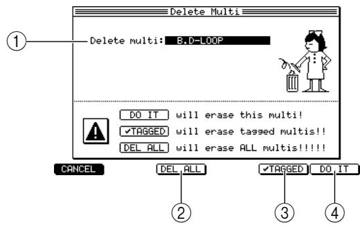
Delete multi field: Selects the multi that will be deleted.
(2) [F3] key (DEL ALL): Displays the Delete ALL Multis popup window, where you can delete all multis from the MPC4000's internal memory.
③ [F5] key (✔ TAGGED): Deletes each multi that you specified by a✔ mark in the Tag field of the list page.
(4) [F6] key (DO IT): Removes the multi that you specified in the Delete multi field.
4. Move the cursor to the Delete Multi field, and turn the [JOG] dial to select the multi that you want to delete.
5. To execute the delete operation, press the [F6] key (DO IT).
Hint: If you press the [F3] key (DEL ALL), all multis will be deleted from internal memory.) If you assigned marks in the Tag field of the list page to specify the multis that you want to delete, you can press the [F5] key (TAGGED) to delete all the multis you specified.
Saving or loading a multi
You can save or load multis/parts to or from a storage device.
Saving a multi
Here's how to save a multi from internal memory to an internal or external storage device. Since all multis in internal memory will be lost when you turn off the power, you must use this procedure to save any multis that you want to keep.
1. Press the [SAVE] key.
The Save page will appear.
![AKAI MPC4000 - Press the [SAVE] key. - 1](/content/2025/01/152367/images/65dbf124433d94570f964f3c78c8e52f00a4f563a45ec8bc3973dd8366761acd.jpg)
① Disk information: Indicates the storage device that is selected as the save-destination.
② Type field: Selects the type of data that will be stored.
③ Disk field: Selects the save-destination storage device.
Save field: Indicates the folder within the save-destination storage device.
⑤ File list block: Displays the folder structure within the selected storage device.
2. Move the cursor to the Type field, and turn the [JOG] dial to select SAVE MULTIs.
When you select SAVE MULTIs, the following parts of the display will change.
![AKAI MPC4000 - Move the cursor to the Type field, and turn the [JOG] dial to select SAVE MULTIs. - 1](/content/2025/01/152367/images/4ac576f606d723d25d5348a444f90b40a02af9c1f355ffb7ab08a1357d2097cc.jpg)
① Data list: Shows the data in the MPC4000's internal memory.
② Size field: Indicates the size of each multi.
3. Move the cursor to the Disk field and turn the [JOG] dial.
The Disk List popup window will appear.
![AKAI MPC4000 - Move the cursor to the Disk field and turn the [JOG] dial. - 1](/content/2025/01/152367/images/20be135a6000a10a0ea19aabfdf8a7f1c67e6c155f5b465b51861a5e9b42be98.jpg)
4. Move the cursor to the storage device on which you want to store the multi, and press the [F6] key (SELECT).
That device will be selected as the store-destination device, and the popup window will close.
5. Move the cursor to the data list, and use the CURSOR [Δ] /[▼] keys to move the cursor to the multi that you want to save.
The multi to which you move the cursor will be selected for saving. An asterisk * will be displayed in front of the name of any multi that you have modified after it was last saved or loaded.
Hint: When the cursor is located in the data list, you can also turn the [JOG] dial to select a multi to save.
6. Move the cursor to the file list block, and select the folder in which you want to save the multi. Use the CURSOR [] / [] keys to move upward or downward through the folder hierarchy, and the CURSOR [] / [] keys to select a folder within the same level.
Hint: You can press the [F3] key (NEW) to create a new folder in the current level.
7. Press the [F6] key (DO IT).
The Save a Multi popup window will appear, where you can execute the save operation.
![AKAI MPC4000 - Press the [F6] key (DO IT). - 1](/content/2025/01/152367/images/10f3694383f73ce134481e0f8cddc4066d2211f0ceec23009f6d9ea1e51726c8.jpg)
① Save field: Specifies how the programs and samples included in the multi will be saved.
② Replace same files field: Specifies how identically-named programs or samples existing in the save-destination will be handled.
Hint: If the File exists lookup appears when you press the [F5] key, an identically-named multi already exists on the storage device. If this occurs, take one of the following actions.
Press the [F3] key (RENAME) and rename the multi.
Press the [F5] key (REPLACE) to overwrite the existing multi.
- Move the cursor to the Save field, and turn the [JOG] dial to select one of the following ways in which the programs/samples will be saved.
WITH PROGRAMS & SAMPLES: The programs and samples included in the multi will be saved with it.
WITH PROGRAMS: The programs included in the multi will be saved with it. (Samples will not be saved.)
MULTI ONLY: Only the multi will be saved.
WITH NEW & MODIFIED: Of the programs/samples included in the multi, only those that were modified after being saved or loaded will be saved.
- If you selected WITH PROGRAMS & SAMPLES or WITH PROGRAMS in step 8, move the cursor to the Replace same files field, and turn the [JOG] dial to select how the programs/samples will be saved.
YES: Existing data will be overwritten.
NO: Identically-named data will not be saved.
- To execute the Save operation, press the [F5] key (DO IT).
The multi will be saved in the folder you specified. If you selected other than MULTI ONLY in step 8, the corresponding programs/samples will be saved as well.
Loading a multi
Here's how to load a multi from a storage device.
- Press the [LOAD] key.
The Load page will appear. Here you can load files that were saved on a storage device.
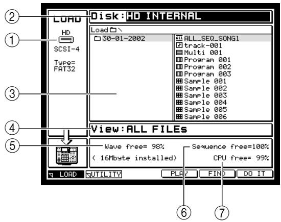
① Disk information: Indicates the MPC4000's internal storage device or an externally-connected storage device that is currently selected for operations.
② Disk field: Selects the storage device from which the multi will be loaded.
③ File list block: Displays the hierarchical structure of the storage device you selected.
④ View field: Selects the type of file that will be displayed in the tree.
⑤ Wave free field: Displays the available amount of sample memory in the MPC4000.
⑥ Sequence free field: Displays the available amount of memory in the sequencer section of the MPC4000.
⑦ CPU free field: Displays the available amount of data management memory in the MPC4000.
- Move the cursor to the Disk field, and turn the [JOG] dial to display the Disk List popup window.
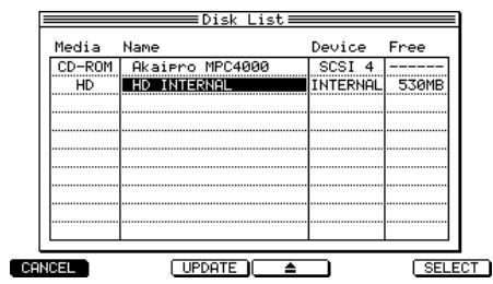
- Move the cursor to the storage device from which you want to load data, and press the [F5] key (SELECT).
The storage device at the cursor will be selected as the loading-source.
- Move the cursor to the View field, and turn the [JOG] dial to select the type of file that you want to load.
By selecting the desired type of file in the View field, you can hide all other types of files.
- In the file list block, move the cursor to the file that you want to load.
Use the CURSOR [] / [] keys to move upward or downward between levels, and use the CURSOR
[Δ ] / [ ] keys to select a folder within the same level.
- Press the [F6] key (DO IT).
The Load a Multi popup window will appear.
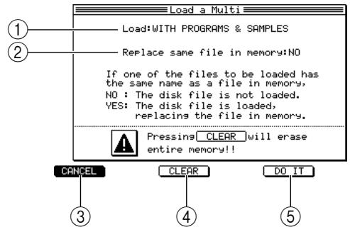
① Load field: Specify how the programs/samples included in the multi will be handled.
② Replace same file in memory field: Specify what will happen if internal memory already contains a program/sample of the same name as a program/sample that is being loaded. (This will be displayed only if you have selected a choice other than MULTI ONLY in ① , above.)
③ [F1] key (CANCEL): Cancels the load operation and closes the popup window.
④ [F3] key (CLEAR): Clears the internal memory.
⑤ [F5] key (DO IT): Executes the load operation.
- Move the cursor to the Load field, and select one of the following choices to specify how the programs/samples included in the multi will be handled.
MULTI ONLY: Only the multi will be loaded.
WITH PROGRAMS: The programs included in the multi will also be loaded. (Samples will not be loaded.)
WITH PROGRAMS & SAMPLES: The programs and samples included in the multi will also be loaded.
- If you selected WITH PROGRAM & SAMPLES or WITH PROGRAMS in step 7, move the cursor to the Replace same sample in memory field, and turn the [JOG] dial to specify how data already existing in memory will be handled.
NO (FASTER): If identically-named programs/samples already exist in memory, that data will not be loaded.
YES: The data will be loaded, overwriting the data currently existing in memory.
- To execute the load operation, press the [F5] key (DO IT).
Hint: If there is insufficient free space in internal memory, it may not be possible to load the selected file. In this case, delete unneeded data from memory to increase the amount of free space.
6 Mixer mode operations
This chapter explains how to use Mixer mode to adjust the mix parameters of the parts.
About Mixer mode
In Mixer mode you can use the part mixer to adjust the mix parameters of each part.
The Part Mixer lets you adjust the volume, pan, and effect bus send level for each part within the currently selected multi. These parameters are in common with the parameters of the multi, and adjusting either will also affect the other one.
The settings of the part mixer are held within the multi. If you want to keep the changes you make, you must save the multi (→ p.54)
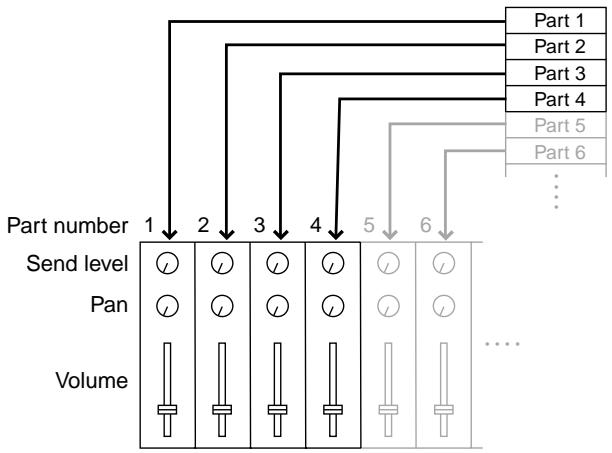
Using the Part Mixer
The part mixer lets you control mix parameters such as volume, pan, and effect bus send level for each part.
- In the main page, select the multi that you want to control. Also make sure that the program you want to use is selected for each part of the multi.
- Press the [MIXER] key.
The Part page of Mixer mode will appear. In this page you can use the part mixer that adjusts the volume, pan, and send level of each part.
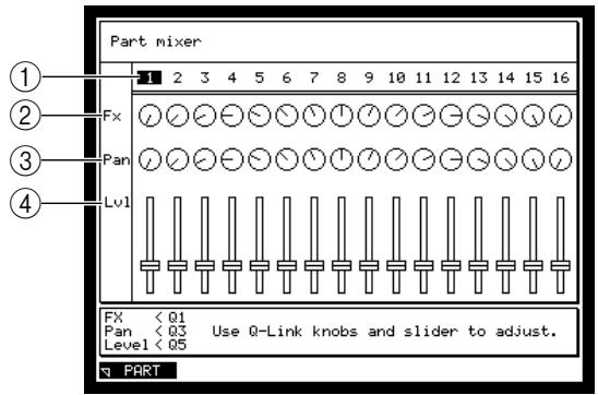
① Part number field: Indicates the part numbers in the multi.
② Fx field: Indicates the send level of the signal that is sent from each part to the effect bus. The effect bus to which the signal is sent can be selected in the Multi mode Mix page (→ p.49)
③ Pan field: Indicates the pan of each part.
(4) Level field: Indicates the volume of each part.
- Turn the [JOG] dial to select the part whose mix parameters you want to adjust.
When the cursor moves to the far right of the screen, the parts will scroll automatically.
Note: The part mixer applies only to the sampler section. It cannot be used to control an external MIDI sound module.
- Use the [Q1]/[Q3] knobs and [Q5] slider of the Q-LINK section to adjust the mix parameters of the currently selected part.
While the Part page is displayed, you can use the [Q1] knob, [Q3] knob, and [Q5] slider to adjust the Fx field, Pan field, and Level field of the currently selected part.
Note: Q -LINK is temporarily turned off while the Part page is displayed.
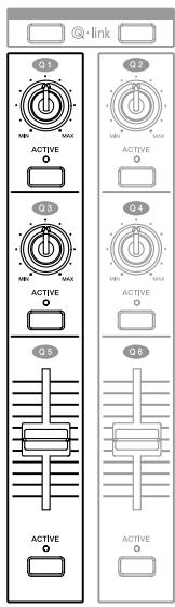
- Repeat steps 2-3 to adjust the mix parameters of each part.
- If you want to keep the changes you made to the part mixer settings, save the multi.
7 Effects
The MPC4000 contains four effect units (effects 1-4) that you can use to process the programs of the sampler section. For each effect unit, you can select one of 52 effect types, and edit the effect parameters to obtain a wide range of effects.
To use the effects, you will send the signal of each part to the effects via four effect buses (A-D) provided within the MPC4000. When the MPC4000 is in the default state, effects 1-4 are connected to effect buses A-D. When you select an effect bus for each part and raise the send level to that effect bus, the signal will be sent to the corresponding effect.
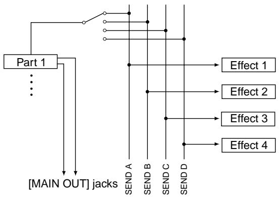
When the MPC4000 is in the default state, the processed signal (the effect sound) is sent directly to the [MAIN OUT] jacks, mixed with the output signal of the parts (the direct sound), and output from the [MAIN OUT] jacks.
Settings such as the effect type used by effects 1-4, the effect parameter settings, and the effect bus routing are stored in the currently selected multi. Since the contents of the multi will be lost when you turn off the power, you must save the currently selected multi if you want to keep the settings (for details on how to save a multi → p.54).
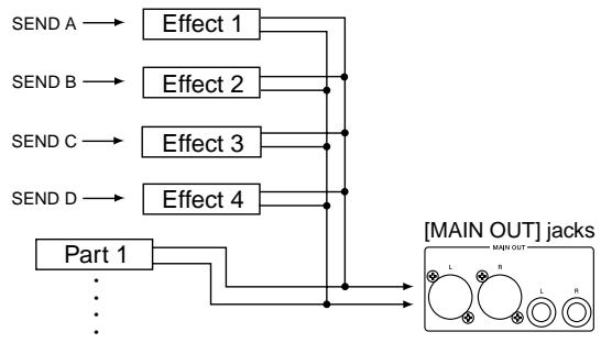
Hint: The various effect types are either mono-in/mono-out or mono-in/stereo-out. However if necessary, you can link two effects and use them as a stereo-in/stereo-out effect. You can change the input/output routing of the effect if desired. For details, refer to the PDF reference manual.
Basic effect operations
Here's how to select an effect type for effects 1-4, select the effect bus for each part, and set the send level.
1. Press the [EFFECT] key, and then press the [F1] key (SELECT).
The Select page will appear. In this page you can change the effect routing and select the effect type.
![AKAI MPC4000 - Press the [EFFECT] key, and then press the [F1] key (SELECT). - 1](/content/2025/01/152367/images/024a7d9b901e7cf949c2b4175bb098a7f3e1f8c7162a1fa1e4303a0effeb0260.jpg)
① In field: Selects the input source for effects 1-4. By default, effect buses SEND A-D are assigned to effects 1-4.
② Effect field: Select the effect type used by effects 1-4.
③ Out field: Select the jacks that will be the output destinations for effects 1-4. You can choose from L/R, 1-8 (individual outputs 1-8), 1 / 2,3 / 4,5 / 6,7 / 8, or OFF (not sent).
④ Stereo link field: By turning this field on, you can link effects 1/2 and 3/4 and use them as stereo-in/stereo-out effects.
(5) [F2] key (EDIT): Displays the Edit page, where you can edit effect parameters.
(6) [F3] key (MIX): Displays the Mix page, where you can make settings for the signals that are output from the effects.
- If you want to select an effect type, move the cursor to the Effect field of effects 1-4, and turn the [JOG] dial.
The Select Effect Type popup window will appear. In this popup window you can select the effect type.
![AKAI MPC4000 - Press the [EFFECT] key, and then press the [F1] key (SELECT). - 2](/content/2025/01/152367/images/9d71cd9addfebaf48ff3f6e0d8f1495e654498312098ddfc42d85b7b37917823.jpg)
① Effect list: Selects the effect type that will be used.
(2) [F1] key (CLOSE): Cancels the operation and closes the window.
(3) [F3] [F6] key (SELECT): Finalizes the effect type you selected in ①.
- Turn the [JOG] dial to select the effect type.
The MPC4000 provides the following effect types. For the effect produced by each type and details of the parameters, refer to the reference manual.
| Effect types |
| CHORUS>MONO |
| CHORUS>STEREO |
| CHORUS>XOVER |
| CHORUS+DELAY |
| COMPRESSOR/LIMITER |
| DELAY>MONO |
| DELAY>MULTI TAP |
| DELAY>PAN |
| DELAY>PING PONG |
| DELAY>STEREO |
| DELAY>XOVER |
| DIGITAL EQ |
| DISTORTION |
| ENHANCER |
| EXPANDER |
| FLANGER>MONO |
| FLANGER>PAN |
| FLANGER>STEREO |
| FLANGER>EXPANDER |
| FLANGER+DELAY |
| NOISE GATE |
| PAN>AUTO PAN |
| PAN>TRIGGER PAN |
| PHASER>MONO |
| PHASER>PAN |
| PHASER>STEREO |
| Effect types |
| PHASER>XOVER |
| PHASER+DELAY |
| PITCH CORRECTOR |
| PITCH SHIFTER |
| REVERB>AUDITORIUM |
| REVERB>BIG HALL |
| REVERB>BIG ROOM |
| REVERB>BRIGHT HALL |
| REVERB>BRIGHT PLATE |
| REVERB>DRUM BOOTH |
| REVERB>LIVE HOUSE |
| REVERB=MEDIUM HALL |
| REVERB=MEDIUM ROOM |
| REVERB>NON LINEAR |
| REVERB>PLATE |
| REVERB>REVERSE |
| REVERB>SMALL HALL |
| REVERB>SMALL ROOM |
| REVERB>STUDIO |
| REVERB>THEATER |
| REVERB>VOCAL PLATE |
| REVERB>WAREHOUSE |
| ROTARY SPEAKER |
| TAPE ECHO |
| WAH>AUTO WAH |
| WAH>TOUCH WAH |
- After you have selected an effect type, press the [F6] key (SELECT).
The selected effect type will be finalized, and the window will close.
- Press the [F3] key (MIX).
The Mix page will appear. In this page you can adjust the level of the signal that is output from each effect, and specify whether the direct sound will be output from the effect.
![AKAI MPC4000 - Press the [EFFECT] key, and then press the [F1] key (SELECT). - 3](/content/2025/01/152367/images/9f5d4ca4e872e84947e84406b0faafd0a2b8edd418e8bf1d4c080ebc1bc209f3.jpg)
① Level field: Adjusts the signal level that is output from each effect.
② Direct signal field: Selects whether the signal (unprocessed sound) from the parts that select the corresponding FX bus will be sent to the output jacks.
If this is on, the signal from the part(s) and the signal processed by the effect will be mixed immediately before the output jacks.
If this is off, the corresponding part(s) will be muted, and only the signal processed by the effect will be sent to the output jacks.
Hint: Turn this field ON for effects that are normally mixed with the unprocessed sound, such as reverb or delay.
Turn this field OFF for effects that process the original sound itself, such as compressor or distortion.
- Move the cursor to the Direct signal field, and turn the [JOG] dial to switch the setting on/off as appropriate.
If this is on, the signal from the part(s) and the signal processed by the effect will be mixed and output. Use the Wet/Dry field of the effect parameter to adjust the mix balance of the direct sound and effect sound. - As necessary, move the cursor to the Level field and turn the [JOG] dial to adjust the signal level that will be output from the effect.
- Press the [F2] key (EDIT).
The Edit page will appear. This page displays the effect parameters for the currently selected effect.
![AKAI MPC4000 - Press the [EFFECT] key, and then press the [F1] key (SELECT). - 4](/content/2025/01/152367/images/735099d2c876648dd0a4ba0ee167136670312757b9c1f22b2457850785dd9707.jpg)
Hint: For details on setting effect parameters, refer to the following section.
- Move the cursor to the Wet/Dry field, and turn the [JOG] dial to adjust the mix balance between the direct sound and the effect sound.
The Wet/Dry field adjusts the mix balance of the signal that is sent directly from the part(s) (=Dry) and the signal processed by the effect (=Wet). The appropriate setting for the Wet/Dry parameter will depend on the effect type and on how you are using the effect.
- To mix the direct sound and effect sound immediately before the output jacks
In step 6, turn the Direct signal field on, and set the Wet/Dry field to 100 / 0 (effect sound = 100% ). Use this method when you want an effect such as reverb or delay to be shared between multiple parts.
- To send only the effect sound directly from the effect to the output jacks
In step 6, turn the Direct signal field off, and set the Wet/Dry field to 100 / 0 (effect sound = 100% ). Use this method when you want to apply compressor or distortion to only a specific part.
- To send the original sound + effect sound from the effect directly to the output jacks
In step 6, turn the Direct signal field off, and set the Wet/Dry field according to the type of effect and the desired effect depth. Use this method when you want to apply an effect such as chorus to only a specific part.
- Repeat steps 1-6 to make settings for other effects in the same way.
- Press the [MULTI] key, and then press the [F2] key (MIX).
The Mix page will appear. In this page you can adjust the mix parameters of the parts that are included in the currently selected multi. For a detailed explanation of this page, refer to page 49.
- Move the cursor to the Send field of the part to which you want to apply an effect, and select the effect bus to which the signal will be sent.
- Move the cursor to the Fx field.
Adjust the level of the signal that will be sent to the effect bus selected in step 10.
At this time, play back a sequence or strike the pads to make sure that the desired effects are applied.
- If necessary, move the cursor to the Level field and adjust the output level of the part.
- Repeat steps 11-12 to make settings in the same way for other parts.
- If you want to keep the effect type settings you selected for each effect, save the multi as described on p.54.
Editing the effect parameters
Here's how to adjust the parameters of the effect types used by effects 1-4.
- Press the [EFFECT] key, and then press the [F1] key.
The Select page will appear. - Move the cursor to the Effect field of the effect whose parameters you want to adjust.
- Press the [F2] key (EDIT).
The Effect mode Edit page will appear. This page displays the parameters of the effect you selected in step 2. The contents of the page will differ depending on the currently selected effect type.
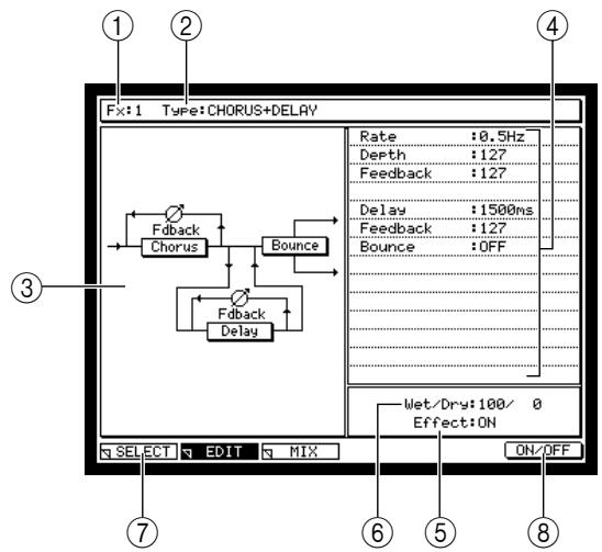
① Fx field: Selects the effect number (effect 1-4) whose parameters will be displayed.
② Type field: Selects the effect type that will be used by ①.
③ Graphic display: Shows a block diagram for the selected effect type.
Parameter field: Adjusts the effect parameters for this effect.
⑤ Effect field: Switches the effect on/off.
(6) Wet/Dry field: Adjusts the mix balance between the direct sound (Dry) and effect sound (Wet).
[F1] key (SELECT): Displays the Select page.
[8] [F6] key (ON/OFF): Switches the effect on/off.
- If you want to change the effect (effect 1-4) that is shown in the display, move the cursor to the Fx field and turn the [JOG] dial to select the desired effect.
If necessary, you can move the cursor to the Type field of this page and change the effect type used by that effect.
- Move the cursor to the effect parameter in the parameter field that you want to edit.
- Use the [JOG] dial to adjust the effect parameter.
It is helpful to play back a sequence or strike the pads so that you can hear the result.
Refer to the PDF reference manual for details on the parameters of each effect type and their range.
- Repeat step 5-6 to finish editing the parameters.
- If you want to keep your changes, save the multi.
Your changes will be saved within the multi. If you want to keep the current effect settings, save the currently selected multi.
8 Recording and editing samples
This chapter explains how you can record an external audio source (CD, record, vocal, etc.) connected to the MPC4000, and edit the sample so that you can use the Sampler section to play it.
About samples
A "sample" is one of the individual pieces of waveform data in memory from which the sounds of the Sampler section is constructed. To add a sample to memory, you can record (sample) it via the [REC IN] jack or [DIGITAL IN] jack, or load a sample file from a storage device.
Each sample has its own settings for the following parameters.
- Sample name
- Note at which the sample will play at its original pitch
Tuning - Start point (the location at which playback will begin)
- End point (the location at which playback will stop)
- Loop playback on/off
- Loop start point (the location at which looping will start)
- Loop end point (the location at which looping will end)
Please be aware that simply loading or sampling a sample into memory does not mean that you will be able to play it from the pads or the sequencer. In order to play samples, you must first assign them to a program.
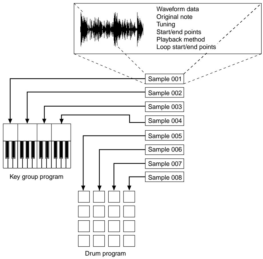
All of the samples that can be played on the MPC4000 are held in memory. When you turn off the power of the MPC4000, all samples in memory and their settings will be lost. If you want to keep the samples, you must save the samples (in some cases, the samples and programs) to a storage device before you turn off the power. (For the Save procedure → p.77)
Recording (sampling) an external source
Here's how you can record an external analog source connected to the REC IN [LINE/MIC] jacks or [PHONO] jacks, and add the sample to the currently selected program.
Hint: In order to play a sample that you record, you must assign the sample to a program. In this example, we will show how to assign the sample to the program that is created in memory when you turn on the power of the MPC4000.
Preparations before recording
- Connect the audio source that you want to record (CD player, mic, turntable, etc.) to the rear panel REC IN [LINE/MIC] jacks or the REC IN [PHONO] jacks.
Make sure that the rear panel [INPUT SELECT] switch is set to select the appropriate jacks.
- Press the [RECORD] key.
The Record page will appear. In this page, you can make various settings for recording an external audio source.
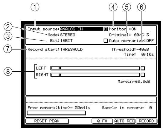
① Input source field: Selects the source that will be recorded.
② Mode field: Selects whether to record in stereo or monaural.
③ Bit depth field: Selects the bit depth (16 bit or 24 bit) for recording.
④ Monitor field: Selects whether to monitor the input source during recording.
⑤ Original field: Selects the note (note name) that will play that sample at its original pitch.
⑥ Auto normalize field: If this field is on, the recorded sample will be normalized automatically.
⑦ Record start field: Selects how recording will be started. You can select THRESHOLD (start recording when the input signal exceeds a specified level) or MANUAL (start recording manually).
Level meters: These are level meters (with peak indicators) that show the level of the input signal. If the input signal clips, the over level indicator at the right () will be highlighted. If Record start is set to THRESHOLD, a rectangle indicating the threshold level will be displayed.
- Move the cursor to the Input source field, and select the source that you want to record.
ANALOG IN.....Record the input signal from the rear panel REC IN [PHONO] jacks or the REC IN [LINE/MIC] jacks.
DIGITAL IN.......Record the input signal from the rear panel [DIGTAL IN] jack. (If the ID-4D option is installed)
MAIN OUT......Record the same signal as is output from the rear panel [MAIN OUT] jacks.
For this example, select ANALOG IN.
- Move the cursor to the Mode field, and select either stereo or monaural recording.
You have the following choices.
STEREO.......Record the left/right input signals as a stereo sample.
MONOL Record the left input signal as a mono sample.
MONO R.....Record the right input signal as a mono sample.
-
Move the cursor to the Bit depth field, and select the bit depth (24 bit or 16 bit) for recording.
-
Move the cursor to the Record start field, and select how recording will be started.
-
If you want to start recording automatically
Set the Record Start field to THRESHOLD. With this setting, recording will begin automatically when the level of the input signal exceeds the threshold you specified.

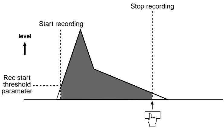
- If you want to start recording manually
Set the Record Start field to MANUAL. With this setting, recording will begin when you press the appropriate key. This method is convenient when you are recording a drum loop etc. from a CD or record.
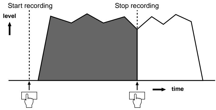
7. Move the cursor to the Time field, and set the recording time.
When you record, recording will stop automatically when the time specified here has elapsed.
Hint: You can also manually stop recording. For example if you are recording a phrase of an unknown length, you can set the Time field to a fairly long value, and then manually stop recording.
8. Press the [WINDOW] key.
The Recording Setup popup window will appear. In this window you can set various options related to recording.
![AKAI MPC4000 - Press the [WINDOW] key. - 1](/content/2025/01/152367/images/0f35397933d27290ac873e461131ed63ebf6b2b694c15364eea71cfb6a0805b4.jpg)
① System sampling rate field: Indicates the sampling rate of the entire system (set in GLOBAL mode). This field is only for display, and cannot be changed here.
② Bit field: Selects the resolution (16-bit or 24-bit) used for recording.
③ Pre-recording time field: Specifies how much of the signal preceding the actual start of recording will be included in the recording.
- Set the Pre-recording time field and the Bit field as necessary, and press the [WINDOW] key or the [F1] key (CLOSE) to return to the previous screen.
For example if you have selected THRESHOLD as the Record start method, you can set the Pre-recording time field to several hundred milliseconds so that the attack portion of the waveform will not be omitted from the recording.
![AKAI MPC4000 - Press the [WINDOW] key. - 2](/content/2025/01/152367/images/ab47b5ac9743aa80d9d91db1edfefa9f4120521c58831b3a95f37444f0617ea3.jpg)
- While you watch the level meters, play the audio source that you want to record, and use the [REC GAIN] knob to adjust the recording level.
To obtain the best S/N ratio, set the recording level as high as possible without allowing the over-level indicators to light at the loudest volume.
Note: The [REC GAIN] knob has no effect if you have selected DIGITAL IN or MAIN OUT as the input source.
Actual recording
The procedure for actual recording will differ slightly depending on how you start and end recording.
-
Press the [F6] key (RECORD).
-
If MANUAL is selected as the Record start method
Recording will begin the instant you press the [F6] key (RECORD). During recording, the Recording... callback on the Record button will appear.
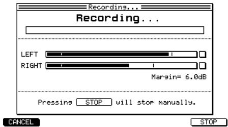
- If THRESHOLD is selected as the Record start method
The Record Ready popup window will appear. Play the audio source that you want to record. Recording will begin the instant that the input signal exceeds the threshold level.
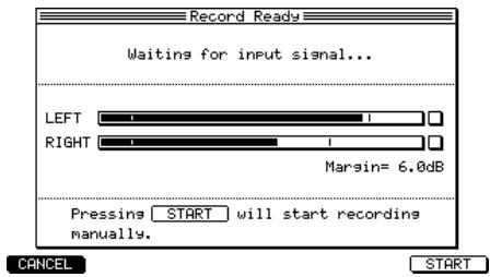
Hint: Even if THRESHOLD is selected as the Record start method, you can press the [F6] key (START) in the Record Ready popup window to begin recording manually.
- To manually stop recording, press the [F6] key (STOP).
Alternatively, recording will stop automatically when the time you specified in the Time field has elapsed.
When recording ends, the Keep or Retry popup window will appear.
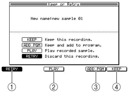
① [F1] key (RETRY): Discards the sample.
② [F3] key (PLAY): Auditions the sample.
(3) [F5] key (ADD PGM): Retains the sample in memory, and adds it to the program.
(4) [F6] key (KEEP): Retains the sample in memory.
- Press the [F3] key (PLAY) to audition the sample. If you want to re-try the recording, press the [F1] key (RETRY). If you are satisfied with the sample, press the [F5] key (ADD PGM).
If you press the [F1] key (RETRY), the sample will be discarded and you will return to the Record page. If you press the [F5] key (ADD PGM), the Add to Program popup window will appear.
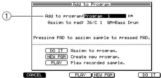
① Add to program field: From the programs currently in memory, selects the program to which this sample will be assigned. The fields that are displayed will depend on the type (key group or drum) of the selected program.
- To assign the sample to a program, use the Add to program field to select the desired program.
When you turn on the power of the MPC4000, one program (drum type) is created automatically. Unless you have loaded a program from a storage device or created a new program after power-on, this drum program is the only one that will be available for selection here.
Hint: You can press the [F4] key (NEW PGM) to create a new program, and add your newly recorded sample to that program.
-
Set the various parameters according to the type (key group or drum) of the program you selected in step 4.
-
If you selected a key group program
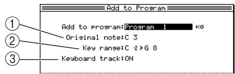
① Original note field: Specifies the note at which the sample will sound at its original pitch.
(2) Key range field: Specifies the range of the key group to which the sample will be assigned.
③ Keyboard track field: Within the key group to which the sample is assigned, specifies whether the pitch will rise or fall according to the note range (ON), or whether all notes will sound the same pitch (OFF).
- If you selected a drum program
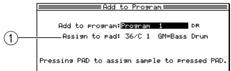
① Assign to note field: Selects the note to which the sample will be assigned. You can turn the [JOG] dial to select a note number, or strike a pad directly to specify it.
Hint: The sample you record will be assigned a default name of "Sample xxx" (xxx will be a number indicating the number of samples you recorded). If desired, you can turn the [JOG] dial in the Keep or retry window to assign a new name to the sample.
- Press the [F6] key (DO IT).
The sample will be assigned to the selected program, and you will return to the Record page.
- Repeat steps 1-6 to record other samples in the same way.
Making various settings for a sample you recorded
Here's how you can specify the playback start/end locations, loop playback on/off, and loop start/end locations for a sample you recorded into memory.
- Press the [SAMPLE] key, and then press the [F1] key (List).
The Sample mode Sample list page will appear. This page shows a list of the samples currently in memory.
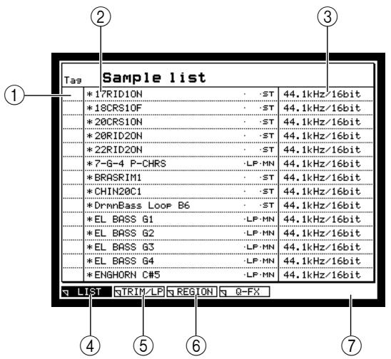
① Tag field
② Sample field: Lists the names of the samples currently in memory. Newly recorded samples and samples that were edited after being loaded or saved will have a * symbol displayed in front of their name.
The characters displayed at the right of the sample name have the following significance.
ST . Stereo sample
MN . Monaural sample
LP . Loop playback is ON
③ Sampling rate/Bit field: Displays the sampling rate/bit depth of each sample shown in field ②.
④ [F1] key (LIST): Accesses the sample list page from another page.
[5] [F2] key (TRIM/LP): Accesses the Trim/Loop page, where you can make trim and loop settings for a sample.
[6] [F3] key (REGION): Accesses the Region page, where you can divide a sample into regions and edit them.
[7] [F4] key (Q-FX): Accesses the Quick FX Resampling popup window, where you can apply effects to a sample and resample it.
2. Press the [F2] key (TRIM/LP).
The Trim/Loop page will appear. In this page you can make trim and loop settings for each sample.
![AKAI MPC4000 - Press the [F2] key (TRIM/LP). - 1](/content/2025/01/152367/images/84bc665baa00e263c1f919c0ae915e4a1f401bfdca3599004ee9a83a9287bd7f.jpg)
① Sample field: Selects the sample that will be edited.
② Sampling rate/Bit field: Indicates the sampling rate and bit depth of the sample shown in ①
③ View field: Selects the displayed waveform; either LEFT (left channel only), RIGHT (right channel only), or MIX (both channels mixed).
④ Monitor field: Selects either SAMPLE, PROGRAM, or MULTI as the unit for monitoring.
⑤ Start field: Specifies the playback start point of the sample in single-sample units.
⑥END field: Specifies the playback end point of the sample. By default, this is displayed in single-sample units.
⑦ Waveform display field (upper): Displays the waveform of the entire sample.
⑧ Lp start field: Specifies the loop start point of the sample in single-sample units.
(9) Lp end field: Specifies the loop end point of the sample. By default, this is displayed in single-sample units.
⑩ Play mode field: Selects the playback method for the sample.
11 Waveform display field (lower): According to the field currently selected in the display, this area displays the waveform before and after the start point, the waveform before and after the end point, or the waveform before and after the loop start/end point.
![AKAI MPC4000 - Press the [F2] key (TRIM/LP). - 2](/content/2025/01/152367/images/024bbead1754ee6a8d33238f669056cdc85addc5e13efbd65a9fc912fc2ab8b2.jpg)
Play mode=Loop
![AKAI MPC4000 - Press the [F2] key (TRIM/LP). - 3](/content/2025/01/152367/images/e8e723a6ccb9dbac0562e5c25db975bdf486a1ce58eb7c94a1ca886ac83554d3.jpg)
Play mode=No Loop or ONE SHOT
[12] [F1] key (LIST): Accesses the Sample List page.
[3] [F2] key (TRIM/LP): Accesses the Trim/Loop page from another page.
[4] [F3] key (REGION): Accesses the Region page.
[15] [F4] key (Q-FX): Accesses the Q-FX page, where you can apply effects to the currently selected sample to create a new sample.
[16] [F5] key (EDIT): Accesses the Sample Edit popup window, where you can edit the sample.
[17] [F6] key (P▶ALL): Plays the entire sample once. The start/end points and loop start/end points will be ignored.
-
Move the cursor to the Sample field, and turn the [JOG] dial to select the sample that you want to edit.
-
Move the cursor to the Monitor field, and turn the [JOG] dial to select "SAMPLE."
Note: If the Monitor field is set to "MULTI" or "PROGRAM," the currently selected sample will be assigned to a program, and you will also need to select the appropriate program and part in order to monitor the sample.
- Move the cursor to the Play mode field, and select the playback method for the sample.
NO LOOP. The sample will play from the start point to the end point, without looping. If you release the pad (key) while the sample is playing, playback will stop at that point.
LOOP. The sample will begin playing from the start point when you press the pad (key), and will continue repeating from the loop start to the loop end points as long as you continue holding down the pad (key).
ONE SHOT...... When you press the pad (key), the sample will play back once from the start point to the end point.
![AKAI MPC4000 - Press the [F2] key (TRIM/LP). - 4](/content/2025/01/152367/images/307d4292ee2ddf40064ef49ea44f5ad3966a9c18354c38343fb4952a00f556a3.jpg)
- Move the cursor to the Start field, and specify the start point for the sample.
To change the value of the start point, you can either turn the [JOG] dial, or use the numeric keys to directly input the number of samples and then press the [ENTER] key.
Hint: By holding down the [SHIFT] key and pressing the CURSOR[ /][ ] keys, you can move the decimal place that will be modified by the [JOG] dial. It is convenient to start with a higher decimal place, and then move successively to lower decimal places as you make more precise adjustments.
- Press a pad (or play a MIDI keyboard connected to the [MIDI IN] connector) to check the start point that you specified.
When you press pads 1-12 or pad 16, the sample will play from the start point. In the Trim/Loop page, the function of pads 13-15 will change as follows.
Pad 13 (PLAY LOOP)......The loop region will play while you hold down the pad. If you hold down the [SHIFT] key and press pad 13, playback will continue even if you release the pad. (To stop playback, press the pad once again or press the [SHIFT] key.)
Pad 14 (PLAY TO)............The sample will play from slightly before the currently selected location to the current location.
Pad 15 (PLAY FROM)......The sample will play from the currently selected location to a point slightly later.
- If you want to view the waveform near the start point at a higher magnification, hold down the [SHIFT] key and press the BLOCK CURSOR [▼] key to zoom-in the waveform display field (lower line).
The lower waveform display field lets you view specific areas of the waveform, according to the currently selected field. When the cursor is at the Start field, you can hold down the [SHIFT] key and use the BLOCK CURSOR [Δ] / [] keys to zoom-in/out for the waveform display before and after the start point. - Move the cursor to the value of the END field, and specify the end point of the sample in the same way.
- If you selected LOOP as the sample playback method, set the loop start and loop end points in the same way.
- Repeat steps 3-10 to set the playback method, start/end points, and loop start/end points for other samples.
Hint: You can also set the start/end points or loop start/end points by pressing a key while the sample plays back. For details, see the reference manual.
Note: When you turn off the power of the MPC4000, all samples in memory and their settings will be lost. If you want to keep the samples, you must save the samples (in some cases, samples and programs) on a storage device before turning off the power. (For the Save procedure → p.77 )
Applying Q-FX and resampling
The MPC4000 provides a Q-FX (Quick Effect) function that lets you apply effects to a previously recorded sample and re-record (resample) it. This is an easy way to create new samples.
- In the Sample list page, select the sample that you want to resample and press the [F4] key (Q-FX).
The Quick FX popup window will appear, in which you can specify the effects that will be applied to the sample.
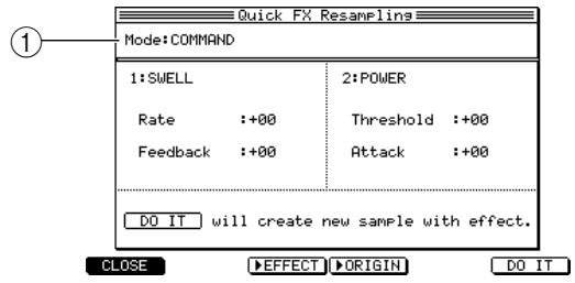
① Mode field: Selects one of the following two Q-FX modes (the way in which effects will be applied).
COMMAND ... Process the sample using one of the commands provided by the Q-FX function. Up to two commands can be used simultaneously.
FX. Apply effects to the sample using the same effect types and parameters as are available in Effect mode. Up to four effects can be used simultaneously.
- Move the cursor to the Mode field, and select Q-FX mode.
Depending on the choice you make here, the display will change as follows.
If you select COMMAND
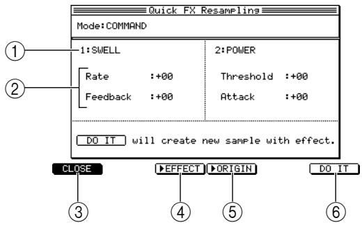
① Command field: Selects up to two commands with which to process the sample.
② Wet/Dry field: Adjusts the balance between the sound processed by FX1-FX4 (Wet) and the original sound (Dry).
③ Effect field: Switches the effect on/off.
(4) [F1] key (CANCEL): Halts the operation and returns to the previous page.
(5) [F3] key (▶EFFECT): Auditions the sound processed by the effect.
[6] [F4] key (▶ORIGINAL): Auditions the original sample.
(7) [F5] key (EDIT): Accesses the Effect page of Effect mode.
[8] [F6] key (DO IT): Executes resampling with Q-FX applied, and returns to the previous page.
If you select EFFECT
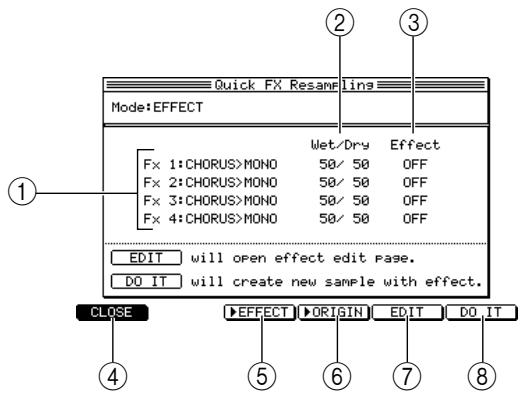
① FX 1-FX 4 field: Selects up to four effect types. You can use the same effect types as in Effect mode.
② Wet/Dry field: Adjusts the balance between the sound processed by FX1-FX4 (Wet) and the original sound (Dry).
③ Effect field: Switches the effect on/off.
(4) [F1] key (CANCEL): Halts the operation and returns to the previous page.
(5) [F3] key (▶EFFECT): Auditions the sound processed by the effect.
[6] [F4] key (▶ORIGINAL): Auditions the original sample.
⑦ [F5] key (EDIT): Accesses the Effect page of Effect mode.
[8] [F6] key (DO IT): Executes resampling with Q-FX applied, and returns to the previous page.
3. Move the cursor to each field of window, and specify the desired command/effect type and parameter settings.
4. If you want to edit the effect parameters of FX 1-FX 4, move the cursor to the desired effect field, and press the [F5] key (EDIT).
The effect edit page for the corresponding effect will appear. Edit the parameter values as desired. (The parameter content is the same as in Effect mode.)
![AKAI MPC4000 - If you want to edit the effect parameters of FX 1-FX 4, move the cursor to the desired effect field, and press the [F5] key (EDIT). - 1](/content/2025/01/152367/images/7bfeecc86f21c0a4839c465b268054e772d5f17fb0d3482570132945681e34dd.jpg)
Hint: For details on the type of available commands and effects, and their parameters, see the PDF reference manual.
5. To apply Q-FX and execute resampling, press the [F6] key (DO IT).
A new sample will be recorded, and the Keep or Retry popup window will appear.
![AKAI MPC4000 - To apply Q-FX and execute resampling, press the [F6] key (DO IT). - 1](/content/2025/01/152367/images/26e417a53453f542e7b40e8cb56799af68b3babc39d0caea32a7b9bdc5890fc2.jpg)
[5] [F4] key (P▶NEW): Plays the edited sample.
[6] [F5] key (ADD PGM): Accesses the Add to Program popup window, where you can add the edited sample to a program.
(7) [F6] key (KEEP): Preserves the edited sample in memory.
- Use the [F3] key (P▶ORIGIN) and [F4] key (P▶NEW) to compare the sample before and after editing.
- If you are satisfied with the resampled result, assign a new name to the sample as desired, and press the [F2] key, [F5] key, or [F6] key to save the new sample.
However if you press the [F2] key (OVER WR), the new sample name will be ignored, and the edited sample will be overwritten onto the original sample, replacing it.
Using edit commands to edit a sample
Here's how to use the edit commands of the Sample page to edit a sample.
- In Sample mode, press the [F5] key (EDIT).
The Sample Edit popup window will appear, where you can edit the sample.

① Edit field: Selects an editing command. The following displays will change according to the command that you select.
② Section field: Selects the region to which the editing command will apply.
Note: The Section field will be displayed only if you have selected a command that requires you to specify an region.
- Move the cursor to the Edit field, and select a command.
The following illustration shows the screen that will appear if you select the DISCARD command, which deletes the waveform data that is outside the specified region. (For details on all the available commands and the items that you can set, see the reference manual.)
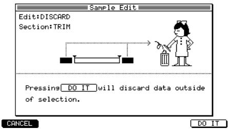
- Move the cursor to each field, and change the settings as necessary.
If you have selected the DISCARD command, move the cursor to the Section field and select one of the following regions.
TRIM............ Between the start and end points
LOOP....... Between the loop start and loop end points
REGION...... The region selected in the Region page
If you select TRIM for the DISCARD command, the region between the start and end points will be kept, and the rest of the waveform data will be deleted.
4. To execute the sample edit command, press the [F6] key (DO IT).
The Keep or Retry popup window will appear, where you can compare the results of the command with the original data, and decide whether to keep the edited result.
![AKAI MPC4000 - To execute the sample edit command, press the [F6] key (DO IT). - 1](/content/2025/01/152367/images/449bc42236c0a662a4265121b20b4401c7a08001fe83cf0a1199d57e51f9bad3.jpg)
- Use the [F3] key (P▶ORIGIN) and [F4] key (P▶NEW) to compare the samples before and after editing.
- If you are satisfied with the edited result, assign a new name to the sample as desired, and press the [F2] key, [F5] key, or [F6] key to save the new sample.
However if you press the [F2] key (OVER WR), the new sample name will be ignored, and the edited sample will be overwritten onto the original sample, replacing it.
Note: These editing commands perform "destructive editing." If you press the [F2] key to overwrite the original sample, you will not be able to recover the original sample.
Dividing a sample
You can divide part of a sample (or the entire sample) into up to 32 regions. you can assign the divided samples to a new program, or you can reconstruct a sequence to play that program, and adjust the tempo and use the divided sample to create a completely new phrase.
For example, this function provides a convenient way in which a drum loop recorded from a CD can be changed to a different tempo and synchronized with the sequencer section.
Specifying the area to be divided
Here's how you can select a sample and specify the area that will be divided into regions.
1. In Sample mode, press the [F3] key (REGION).
The Region page will appear, where you can edit the sample in region units.
![AKAI MPC4000 - In Sample mode, press the [F3] key (REGION). - 1](/content/2025/01/152367/images/cb635d8e4f58b4bbeb8210fddc6d54e1ebec727f7589e285eb89c87615109067.jpg)
① Sample field: Selects the sample that will be edited.
② Sampling rate/Bit field: Indicates the sampling rate and bit depth of the sample shown in (1).
③ View field: Selects the waveform that will be displayed; LEFT (left channel only), RIGHT (right channel only), or MIX (both channels mixed).
④ Monitor field: Selects either SAMPLE, PROGRAM, or MULTI as the unit for monitoring.
⑤ Region start field: Specifies the starting location of the currently selected region (the region start point) in units of one sample.
⑥ Region end field: Specifies the ending location of the currently selected region (the region end point) in units of one sample.
⑦ Waveform display field (upper): Displays all regions. The currently selected region will be highlighted.
⑧ Region field: Specifies the region to be edited by number.
⑨ Waveform display field (lower): According to the field that is currently selected in the display, this area shows the waveform before and after the region start point, or before and after the region end point. You can zoom-in/out the display in this field by holding down the [SHIFT] key and using the BLOCK CURSOR [] /[▼] keys.
[10] [F1] key (LIST): Accesses the Sample List page.
[1] [F2] key (TRIM/LP): Accesses the Trim/Loop page.
[12] [F3] key (REGION): Accesses the Region page from another page.
[13] [F4] key (BPM): Accesses the BPM Match popup window, where you can adjust the length or pitch of a region according to a specified BPM value.
[4] [F5] key (EDIT): Accesses the Sample Edit popup window, where you can edit the sample.
[15] [F6] key (P▶ALL): Plays the entire sample once.
- Move the cursor to the sample field, and turn the [JOG] dial to select the sample that you want to edit.
- Move the cursor to the Region field, and playback [WINDOW] key.
The Number of Regions popup window will appear, letting you specify the number of regions into which the sample will be divided.
![AKAI MPC4000 - In Sample mode, press the [F3] key (REGION). - 2](/content/2025/01/152367/images/57e75b65cd5b968c425b9849c824c607f60e88e8a3ac8c58960e1c99834e8379.jpg)
① Refer to field: Selects the portion of the sample that will be divided into regions.
Number of regions field: Specifies the number of regions into which the selected portion of the sample will be divided.
(3) [F1] key (CANCEL): Cancels the operation and returns to the Region page.
(4) [F6] key (DO IT): Executes the division and then returns to the Region page.
- Move the cursor to the Refer to field, and select one of the following to specify the portion of the sample that will be divided into regions.
TRIM............ Between the start point and end point
LOOP....... Between the loop start point and loop end point
SAMPLE ....... The entire sample
- Move the cursor to the Number of regions field, and specify the number of regions (2-32 regions) into which the specified portion of the sample will be divided.
- To execute the division, press the [F6] key (DO IT).
You will return to the Region page.
Hint: Region settings are non-destructive, so you can redo them as many times as you like. The number and locations at which a sample is divided is remembered for each sample.
Adjusting the region start and region end points
After dividing a sample into regions, you can adjust the start and end points of each region.
- In the Region page, move the cursor to the Region field and turn the [JOG] dial to select the number of the region that you want to adjust.
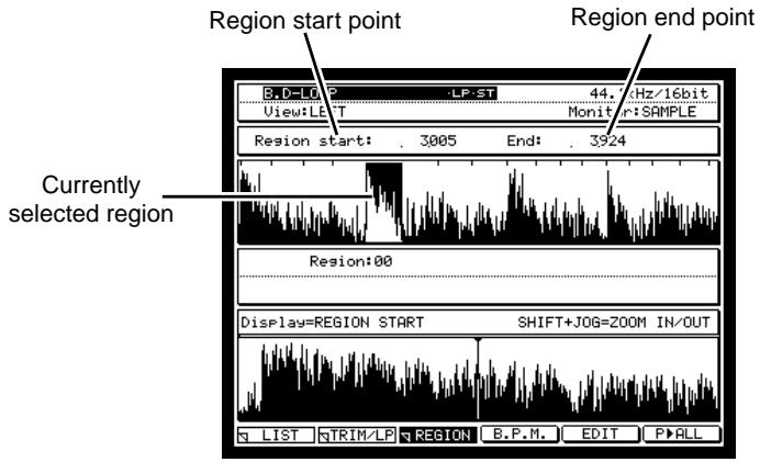
The currently selected region will be highlighted in the upper waveform editing field. The Region start and Region end fields will indicate the starting and ending locations of that region in units of one sample.
- Move the cursor to the Region start field, and edit the region start point.
To adjust the value, you can either turn the [JOG] dial, or use the numeric keys to directly input a number of samples and then press the [ENTER] key.
Hint: By holding down the [SHIFT] key and using the CURSOR[ \langle \downarrow \rangle / [\uparrow ] ] keys, you can change the decimal place that is adjusted by the [JOG] dial. When you edit the region start point of the second or subsequent region, the region end point of the preceding region will change simultaneously.
- If you want to audition the region start point you specified, move the cursor to the Region start field and press pad 14 or 15.
In the Region page, the function of pads 14 and 15 will change as follows.
Pad 14 (PLAY TO) ......Play once from slightly earlier than the currently selected location to the current location.
Pad 15 (PLAY FROM) ....Play once from the current location to a point slightly later.
- If you want to view the waveform in the area of the region start point, hold down the [SHIFT] key and press the BLOCK CURSOR [▼] key to zoom-in the lower waveform display.
When the cursor is located at the Region start field, you can hold down the [SHIFT] key and press the BLOCK CURSOR[▲]/[▼]keys to zoom-in/out the waveform display before and after the region start point.
- Move the cursor to the Region end field, and specify the region end point in the same way.
Hint: When you edit the region end point, the region start point of the following region will change simultaneously.
- As necessary, make adjustments for other regions in the same way.
Using the divided sample to create a sequence and program
Here's how you can use the SLICE SAMPLE edit command to create a new sample for each region that was divided, and register them in memory. At the same time, you can also create a new program to which these samples will be assigned, and a sequence that will play this program.
- In the Region page, press the [F5] key (EDIT).
The Sample Edit popup window will appear.
- In the Edit field, select SLICE SAMPLE.
The SLICE SAMPLE edit command slices the waveform into separate regions and creates a new sample from each region.
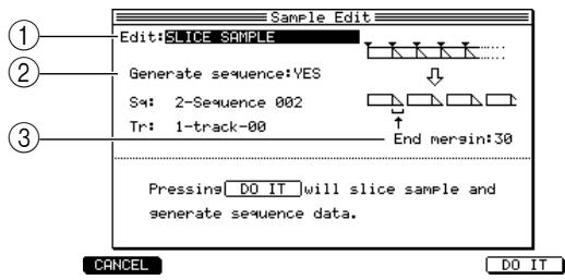
① Edit field: Selects the edit command.
② Generate sequence field: When the SLICE SAMPLE command is executed, this specifies whether a program and sequence will be created at the same time (YES), or whether only the new samples will be created (NO).
③ End margin field: Specifies how much of the waveform data following the region end point will be included when creating the new samples.
- Move the cursor to the Generate sequence field, and select YES.
If you select YES, executing SLICE SAMPLE will automatically create a program to which the sliced samples will be assigned, and a sequence that will successively play the samples of that program.
-
Move the cursor to the Sq field, and select a sequence.
-
Move the cursor to the Tr field, and select a track number.
The new sequence data will be created in the selected track of the selected sequence.
- Move the cursor to the End margin field, and set the end margin.
If you set this to 0, the end point of the divided samples will match the region end point. As you increase this value, the end point of the samples will move later than the region end point. (The start point of the next region will not change.)
Hint: By increasing the value of the End Margin field, you can prevent unnatural-sounding silences from appearing between the samples when you later slow down the tempo of the sequence.
7. Press the [F6] key (DO IT).
The SLICE SAMPLE command will be executed, and a program of the same name as the selected sample will be created. Also, a track with the same name as the sample will be created in the selected sequence.
Playing the track you created
Here's how the new track you created using the SLICE SAMPLE command can be used to play the newly created program.
1. Press the [MAIN] key to access the Main page.
2. Select the sequence and track.
A track with the same name as the original sample has been created in the selected sequence. The program that was newly created by SLICE SAMPLE will be assigned to the part that is selected as the output destination of this track.
3. Play the pads.
You can use the pads to separately play the samples that were divided into regions.
4. Press the [PLAY] key to play back the sequence.
A phrase will play that is essentially the same as the sample before you executed SLICE SAMPLE.
You can use the pads or a MIDI keyboard to edit and overdub the data of this track in the same way as data you recorded conventionally. When you change the tempo of the sequence, the tempo of the phrase will also change.
Changing the pitch of the program you created
Now let's change the pitch of the program you created using the SLICE SAMPLE command.
1. Press the [PROGRAM] key, and then press the [F2] key (KG MIX).
The Key Group Mix page will appear.
2. Move the cursor to the Tune field, and adjust the pitch of the program.
Hint: A program created by executing the SLICE SAMPLE command can be edited in the same way as a conventional program.
Adjusting the tempo of the phrase
You can adjust the tempo of the sample by changing the tuning or applying time-stretch.
1. In the Region page, move the cursor to the Sample field, and select a sample.
2. Press the [F4] key (BPM).
The BPM Match popup window will appear, where you can adjust the length or pitch of the sample according to the BPM value you specify.
![AKAI MPC4000 - Press the [F4] key (BPM). - 1](/content/2025/01/152367/images/ae5a50208ae4ae73a11d1df55d411ce36cb1558163307d95454237215c97bb95.jpg)
① Current tempo field: This is the base tempo from which the tempo adjustment will be made. This value is calculated automatically, according to the settings of the Section field and Beat field, below.
② Section field: Selects the section from which the Current tempo will be calculated.
③ Beat field: Specifies the number of beats in the section that you selected in the Section field.
④ Type field: Selects the way in which the tempo will be changed.
3. Move the cursor to the Section field, and select the section from which the Current tempo will be calculated.
4. Move the cursor to the Beat field, and input the number of beats in the section you selected in the Section field.
When you set the Section field and the Beat field, the tempo calculated from those values will be displayed in the Current tempo field.
5. Move the cursor to the Type field, and select one of the following two choices to specify how the tempo of the sample will be changed.
TUNE
The tempo of the phrase will be changed by changing the pitch of the sample.
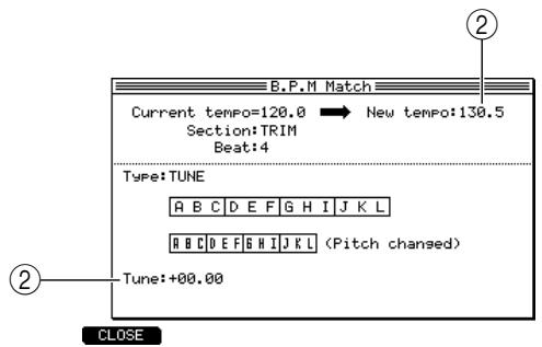
① New tempo field: Specifies the desired result tempo.
② Tune field: Indicates how much the pitch has been changed by the setting you made for the New tempo field. You can also change this value to adjust the New tempo.
STRETCH
The tempo of the phrase will be adjusted using the Time Stretch function.
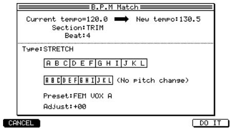
- Move the cursor to the New tempo field, and specify the desired tempo. If you selected TUNE, the value of the Tune field will change according to the tempo you specify in the New tempo field.
- Set the Preset field and the Adjust field.
For details on the Preset field and the Adjust field, see the PDF reference manual.
- To execute the tempo change, press the [F6] key (DO IT).
The Keep or Retry popup window will appear.
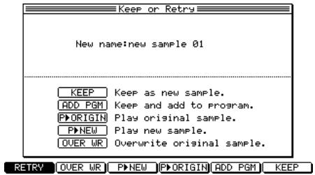
- Use the [F3] key (P▶ORIGIN) and [F4] key (P▶NEW) to compare the sample before and after editing.
- If you are satisfied with the edited result, assign a new name to the sample as necessary, and press either the [F2] key, [F5] key, or [F6] key to save the new sample.
However if you press the [F2] key (OVER WR), the new sample name will be ignored, and the edited sample will be overwritten onto the original file, replacing it.
Note: Tempo change is destructive editing. Be aware that if you press the [F2] key to overwrite the original data, you will not be able to undo this operation.
Saving and loading samples
The following pages explain how to save or load samples to or from a storage device.
Saving samples
Samples in memory can be saved on an internal or external storage device. Since all samples in memory will be lost when you turn off the power of the MPC4000, you must save your samples as described below if you want to keep them.
- Press the [SAVE] key.
The Save page will appear.
- Move the cursor to the Type field, and turn the [JOG] dial to select SAVE SAMPLEs.
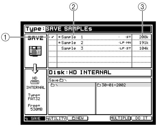
① Tag field: In this field you can assign a tag to individual samples. Use this when you want to save all tagged samples in one operation. Move the cursor to this field, and turn the [JOG] dial to switch the tag on/off.
② Sample list field: Lists the names of the samples that are currently in memory. Newly recorded samples and samples that have been edited after they were last loaded or saved will be indicated by a * symbol in front of their name.
(3) Data size: Indicates the data size of each sample.
- If you want to save an individual sample, move the cursor to the sample list field, and select the desired sample.
- If you want to save multiple samples in a single operation, move the cursor to the Tag field, and assign a tag to the samples that you want to save.
- Move the cursor to the Disk field, and turn the [JOG] dial to access the Disk List popup window. In this popup window you can select the storage device to which the sample(s) will be saved.
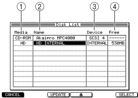
① Media field: Indicates the type of storage device.
② Name field: Indicates the volume name of the storage device.
③ Device field: Indicates how the storage device is connected.
④ Free field: Indicates the free space on the storage device.
- Move the cursor to the storage device on which you want to save the sample(s), and press the [F6] key (SELECT).
That storage device will be selected as the store-destination, and the popup window will close.
- Move the cursor in the file list block to the folder in which you want to save the sample(s).
Use the CURSOR[ \triangleleft ] keys to move upward or downward in the folder hierarchy, and use the CURSOR[ \triangleup ] keys to select a folder within the same level. When you select the save-destination folder, the Save field will show the name of that folder.
Hint: You can press the [F3] key (NEW) to create a new folder in the current level of the folder hierarchy. The file(s) to be saved will be saved in the folder that is selected in the left of the file list (the level that is shown at the right).
If you are saving an individual sample
- If you are saving an individual sample, make sure that the appropriate sample is selected in the sample list field, and press the [F6] key (DO IT).
The selected sample will be saved on the storage device.
If you are saving multiple samples
- If you are saving multiple samples simultaneously, press the [F5] key (MULTIPLE) after step 7.
The Save Multiple Samples popup window will appear, allowing you to select the samples that will be saved.
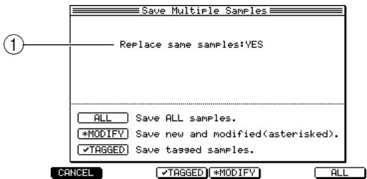
① Replace same samples field: Specifies whether any identically-named samples in the save-destination will be overwritten (YES), or whether such samples will not be saved (NO).
-
As necessary, move the cursor to the Replace same samples field, and make the desired setting.
-
According to the type of samples you are saving, press one of the following function keys.
[F1] key (CANCEL)......Cancel the Save operation and close the popup window.
[F3] key (TAGGED)......Save only the tagged samples and close the popup window.
[F4] key (MODIFY) .... Save only the samples marked by the * symbol and close the popup window.
[F6] key (ALL) .... Save all samples and close the popup window.
The selected samples will be saved to the storage device.
Loading samples
Here's how to load samples from a storage device into the internal memory of the MPC4000.
- Press the [LOAD] key.
The Load page will appear. In this page you can load files that are saved on a storage device.
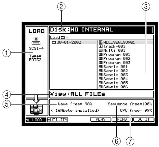
① Disk information: Indicates the storage device that is currently selected for operations.
② Disk field: Selects the storage device from which the data will be loaded.
③ File list block: Displays the internal hierarchy of the selected storage device.
④ View field: Selects the type of file that will be displayed in the file list block.
⑤ Wave free field: Displays the amount of free space in the MPC4000's sampler section memory.
⑥ Sequence free field: Displays the amount of free space in the MPC4000's sequencer section memory.
⑦ CPU free field: Displays the amount of free space in the MPC4000's data management memory.
- Move the cursor to the Disk field, and turn the [JOG] dial to access the Disk List popup window.
- Move the cursor to the storage device from which you want to load data, and press the [F6] key (SELECT).
The storage device at which you placed the cursor will be selected as the source for loading.
- Move the cursor to the View field, and select SAMPLE FILEs as the file type.
With this setting, files other than sample files will be hidden.
- Move the cursor to a file in the file list block.
Use the CURSOR[ \triangleleft ] /[▶] keys to move upward or downward in the folder hierarchy, and use the CURSOR[ \triangleleft ] /[▼] keys to select a different folder or file within the same level.
- Press the [F6] key (DO IT).
The selected sample will be loaded.
9 Creating and editing programs
This chapter explains how to assign samples to a newly created program and edit the various sound parameters to create your own original program.
About programs
The units of sound handled by the Sampler section are called "programs." A program consists of one or more samples (waveform data) together with sound parameters such as filter, envelope, and LFO.
The MPC4000 has two types of program.
- Drum programs
This type of program assigns a different sample to each note number.
Key group programs
This type of program shares a sample between one or more adjacent note numbers (collectively called a "key group"), allowing you to play different pitches with the sample(s).
For either type, sound parameters such as filter, envelope, and LFO can be set independently for each note number/ key group. For each note number/ key group, you can use up to four zones (regions to which a sample is assigned). You can assign a different sample to each zone, and play multiple samples simultaneously or switch between samples according to velocity.
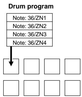
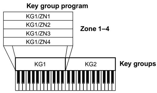
The programs of the MPC4000 are all held in memory. When you turn off the power of the MPC4000, all programs and samples in memory will be lost. If you want to keep your programs, you must save the programs (in some cases, samples and programs) on a storage device before you turn off the power. (For the Save procedure, → p.91)
Creating a new program
In order to create your own original program, you must first create a new, empty program. Here's the procedure.
Hint: When you turn on the power of the MPC4000, an empty drum program (Program 1) will be created automatically. If you use this default program, the following procedure is not necessary.
- Press the [PROGRAM] key, and then press the [F1] key (LIST).
The Program mode List page will appear.
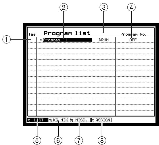
① Tag field: In this field you can assign a tag to individual programs. Use this when you want to save tagged programs in a single operation.
② Program list field: Lists the names of the programs currently in memory. Newly created programs and programs that you have edited after they were last loaded or saved will have a * symbol displayed in front of their name.
③ Program type field: Indicates the type (DRUM or KEY GROUP) of each program listed in ②.
④ Program No. field: Indicates the MIDI program change number that corresponds to each program.
⑤ [F1] key (LIST): Accesses the Program List page from another page.
[6] [F2] key (KG MIX): Accesses the Key Group Mix page, where you can set the level, pan, and output destination for each key group/Note number.
[F3] key (MISC.): Accesses the MISC. page, where you can make settings that apply to the entire program.
[8] [F4] key (ASSIGN): Accesses the Pad Assign page, where you can assign a note number to each pad. This function is displayed only if you have selected a drum program in the program list field.
2. Move the cursor to the program list field, and press the [WINDOW] key.
The Program popup window will appear, in which you can copy or delete a program, or create a new program.
![AKAI MPC4000 - Move the cursor to the program list field, and press the [WINDOW] key. - 1](/content/2025/01/152367/images/c4751857b2429ac6a9d5ae146c82658cec2128399854899230396f0a0ecb6c57.jpg)
① Program name field: Edits the name of the selected program. The Name popup window will appear when you turn the [JOG] dial.
② Type field: Indicates the type of the selected program.
③ [F1] key (CANCEL): Closes the popup window.
(4) [F3] key (CONVERT): Accesses the Convert Program popup window, where you can convert the program type.
[5] [F4] key (DELETE): Accesses the Delete popup window, where you can delete the currently selected program from memory.
[6] [F5] key (NEW): Accesses the Create New Program popup window, where you can create a new program.
[F6] key (COPY): Accesses the COPY popup window, where you can copy the currently selected program.
3. Press the [F5] key (NEW).
The Create New Program popup window will appear.
-
Move the cursor to the Type field, and select the type (either DRUM or KEYGROUP) of the new program. As necessary, move the cursor to the New name field, and assign a name to the new program.
-
Press the [F6] key (DO IT).
A new program will be created in memory.
Assigning samples to a program
This section gives separate explanations for how to assign samples to a newly created program, depending on whether it is a key group program or a drum program.
Assigning samples to a key group program
- Record the samples that you want to assign to the program. (You can either record new samples into memory, or load them from a storage device.)
For details on how to record or load samples, refer to chapter 8.
Hint: If you will be creating a key group program, we recommend that you connect a MIDI keyboard or similar controller to the [MIDI IN] connector so that you can audition the samples conveniently.
- Press the [PROGRAM] key, and then press the [F1] key (LIST).
The Program mode List page will appear.
-
In the program list field, use the CURSOR [] /[▼] keys to select the key group program to which you want to assign samples.
-
Press the [F2] key (KG MIX).
The Key Group Mix page will appear, where you can set the level, pan, and output destination for each key group.
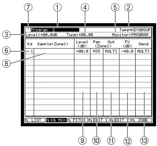
① Program field: Selects the program that you will be editing. A newly created program or a program that you have edited since last loading or saving it will have a * symbol in front of its name.
② Program type field: Indicates the type (DRUM or KEYGROUP) of the program shown in field (1).
③ Level field: Specifies the master level of the program.
④ Tune field: Specifies the master tuning of the program.
⑤ Monitor field: Specifies what will occur when MIDI channel messages are received. If this is set to MULTI, the settings of the currently selected multi will determine which program will respond. If this is set to PROGRAM, the currently selected program will respond regardless of the MIDI channel of the messages.
⑥ KG field: Indicates the key group number.
⑦ Tag field: This has the same function as the Tag field in the Program List page.
⑧ Sample field: Displays the name of the sample assigned to each key group number.
⑨ Level field
⑩ Pan field
① Out field These fields set the playback parameters for each key group.
② FX field
③ Send field
These fields set playback parameters for each key group.
- Move the cursor to the KG field, and press the [WINDOW] key.
The Create New Key Group popup window will appear.
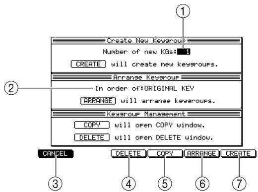
① Number of new KGs field: Specifies the number of new key groups that will be created.
In order of field: This specifies how the key groups will be rearranged. You can choose ORIGINAL KEY (starting with the lowest original note), KEY-RANGE LOW (starting with the key range that has the lowest bottom note), or KEY-RANGE HIGH (starting with the key range that has the highest bottom note).
(3) [F1] key (CANCEL): Cancels the operation and closes the popup window.
(4) [F3] key (DELETE): Accesses the DELETE popup window, where you can delete a key group.
⑤ [F4] key (COPY): Accesses the COPY popup window, where you can copy a key group.
⑥ [F5] key (ARRANGE): Rearranges the key groups according to the order you specified in ②.
(7) [F6] key (CREATE): Creates the number of new key groups you specified in ①.
- Move the cursor to the Number of new KGs field, and specify the number of key groups you want to add.
If you created a new key group program, there will initially be only one key group. You will need to use this popup window to add the desired number of key groups.
- Press the [F6] key (CREATE).
The specified number of key groups will be added, and you will return to the Key Group Mix page.
- Move the cursor to the sample field of each key group, and turn the [JOG] dial to select a sample for each key group.
When you turn the [JOG] dial, the names of the samples in memory will appear successively.
Note: The samples you select in this page will always be assigned to zone 1 of the corresponding key group. If you want to assign samples to zones 2-4, use the Zone page (p.89).
Hint: If the Monitor field is set to "PROGRAM," you can use a MIDI keyboard connected to the [MIDI IN] connector to audition the samples you are assigning, regardless of the state of the current multi.
With the cursor located in the sample field, you can press the [WINDOW] key to view information on the selected sample (sampling rate, bit depth, original note, tuning, etc.).
Unless you specify otherwise, the sample playback method (NO LOOP, LOOP, ONE SHOT) will be the method that has been specified for each sample. However, you are free to change this in the Program mode Zone page (→ p.89) .
- As necessary, move the cursor to the Level, Pan, Out, FX, and Send fields, and set the values.
Each field has the following function.
Level field: Sets the level of each key group.
Pan field: Sets the pan (L50-MID-R50) if the key group is output in stereo. This has no effect if you are using monaural output.
Out field: Sets the output destination jack for each key group. If you select MULTI, the output settings of the multi will be used.
FX field: Indicates the send level of the signal that is sent from the key group to the effect bus.
Send field: Selects the effect bus (OFF, A-D, AB, CD, MULTI) that is used by each key group. If you select MULTI, the settings of the multi will be used. Settings for the effects used can be made in Effect mode.
Note: Please be aware that these fields are valid only for each individual key group, not for the entire program. Use Multi mode to make settings for the entire program.
- Press the [F3] key (PITCH).
The Pitch page will appear, where you can make settings such as tuning and polyphony for each sample.
| Kg | Sample(Zone1) | Span Low Hi | Tune | Pitch (Zone1) | Poly | Mute group |
| 1 | Sample 1 | C 2•G 8 | +00.00 | TRACK | 64 | 64 |
| 2 | Sample 2 | C 2•G 8 | +00.00 | TRACK | 64 | 64 |
| 3 | Sample 3 | C 2•G 8 | +00.00 | TRACK | 64 | 64 |
| 4 | Sample 4 | C 2•G 8 | +00.00 | TRACK | 64 | 64 |
| 5 | Sample 5 | C 2•G 8 | +00.00 | TRACK | 64 | 64 |
① Span Low/Hi field: Specifies the note range of the key group to which the sample is assigned.
② Tune field: Specifies the tuning of the key group.
③ Pitch field: Specifies whether the pitch of the sample assigned to the key group will rise or fall according to the keyboard position (TRACK), or will play at the same pitch for any key (CONST).
④ Poly field: Specifies the maximum polyhony (number of notes) for the key group.
⑤ Mute field: Specifies the mute group (OFF, 1-64) to which the key group will belong. Key groups that belong to the same mute group will not sound simultaneously.
- Move the cursor to the Span Low/Hi field, and specify the note range of the key group to which the sample is assigned.
By default, all key groups are set to sound across the full range of the keyboard (C-2-G8). If you want to switch samples by note ranges, you will need to specify the note range for each key group.
Note: If desired, you can intentionally overlap the ranges of two or more key groups. However, this will reduce the total polyphony.
- Move the cursor to other fields, and make the desired settings.
Assigning samples to a drum program
- Record the samples that you want to assign to the program. (You can either record new samples into memory, or load them from a storage device.)
For details on how to record or load samples, refer to chapter 8.
- Press the [PROGRAM] key, and then press the [F1] key (LIST).
The Program mode List page will appear.
- In the program list field, use the CURSOR [Δ] / [] keys to select the drum program to which you want to assign samples.
- Press the [F2] key (KG MIX).
The Key Group Mix page will appear, where you can make settings such as level, pan, and output destination for each note number.
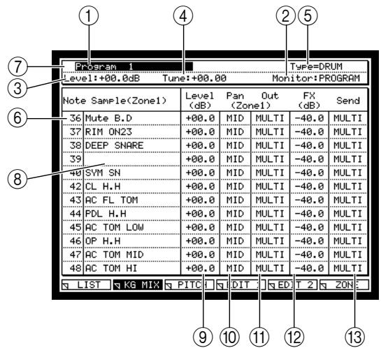
① Program field: Selects the program that you will be editing. A newly created program or a program that you have edited since last loading or saving it will have a * symbol in front of its name.
② Program type field: Indicates the type (DRUM or KEYGROUP) of the program shown in field (1).
③ Level field: Specifies the master level of the program.
(4) Tune field: Specifies the master tuning of the program.
⑤ Monitor field: Specifies what will occur when MIDI channel messages are received. If this is set to MULTI, the settings of the currently selected multi will determine which program will respond. If this is set to PROGRAM, the currently selected program will respond regardless of the MIDI channel of the messages.
⑥ Note field: Indicates the note number.
⑦ Tag field: This has the same function as the Tag field in the Program List page.
⑧ Sample field: Displays the name of the sample assigned to each pad number.
⑨ Level field
Pan field
① Out field These fields set the playback parameters for each pad number.
12 FX field
⑬ Send field
These fields set playback parameters for each pad number.
- Select the note number to which you want to assign a sample, and turn the [JOG] dial to select a sample.
When you turn the [JOG] dial, the names of the samples in memory will appear successively.
Note: The samples you select in this page will always be assigned to zone 1 of the corresponding note number. If you want to assign samples to zones 2-4, use the Zone page (p.89).
Hint: If the Monitor field is set to "PROGRAM," you can use the pads to audition the samples you are assigning, regardless of the state of the current multi.
With the cursor located in the sample field, you can press the [WINDOW] key to view information on the selected sample (sampling rate, bit depth, original note, tuning, etc.).
Unless you specify otherwise, the sample playback method (NO LOOP, LOOP, ONE SHOT) will be the method that has been specified for each sample. However, you are free to change this in the Program mode Zone page (→ p.89) .
- As necessary, move the cursor to the Level, Pan, Out, FX, and Send fields, and set the values.
Each field has the following function.
Hint: You can also strike a pad to select the note number that is assigned to that pad.
Level field: Sets the level of each note number.
Pan field: Sets the pan (L50-MID-R50) if the note number is output in stereo. This has no effect if you are using monaural output.
Out field: Sets the output destination jack for each note number. If you select MULTI, the output settings of the multi will be used.
FX field: Indicates the send level of the signal that is sent from this note number to the effect bus.
Send field: Selects the effect bus (OFF, A-D, AB, CD, MULTI) that is used by each note number. If you select MULTI, the settings of the multi will be used. Settings for the effects used can be made in Effect mode.
Note: Please be aware that these fields are valid only for each individual note number, not for the entire program. Use Multi mode to make settings for the entire program.
7. Press the [F3] key (PITCH).
The Pitch page will appear, where you can make settings such as tuning and polyphony for each note number.
| Program 1 | Type=DRUM | |||
| Level: +00.0dB | Tune: +00.00 | Monitor: PROGRAM | ||
| Note Sample (Zone1) | Tune | Pitch (Zone1) | Poly | Mute group |
| 36 Mute B.D | +00.00 | TRACK | 64 | 64 |
| 37 RIM ON23 | +00.00 | TRACK | 64 | 64 |
| 38 DEEP SNARE | +00.00 | TRACK | 64 | 64 |
| 39 | +00.00 | TRACK | 64 | 64 |
| 40 SVM SN | +00.00 | TRACK | 64 | 64 |
| 42 CL H.H | +00.00 | TRACK | 64 | 64 |
| 43 RC FL TOM | +00.00 | TRACK | 64 | 64 |
| 44 FDL H.H | +00.00 | TRACK | 64 | 64 |
| 45 RC TOM LOW | +00.00 | TRACK | 64 | 64 |
| 46 OP H.H | +00.00 | TRACK | 64 | 64 |
| 47 RC TOM MID | +00.00 | TRACK | 64 | 64 |
| 48 RC TOM HI | +00.00 | TRACK | 64 | 64 |
① Tune field: Specifies the tuning of the note number.
② Pitch field: Specifies whether the pitch of the sample assigned to the note number will rise or fall according to the keyboard position (TRACK), or will play at the same pitch for any key (CONST).
Note: For a drum program, we recommend that you normally leave the Pitch field at CONST. If you change this to TRACK, the pitch may change.
③ Poly field: Specifies the maximum polyphony for the note number.
(4) Mute field: Specifies the mute group (OFF, 1-64) to which the note number will belong. Note numbers that belong to the same mute group will not sound simultaneously. For example if you assign the same mute group to open and closed hi-hat samples, playing one sample while the other sample is sounding will cause the first sound to be muted.
8. Move the cursor to other fields, and make the desired settings.
Pad assignments for a drum program
In addition to the sample assign settings and other parameters for each note, a drum program also contains pad assign settings. For each program, these settings specify the note number that will be output when you strike each pad. If you want to view or modify the note number that is assigned to each pad, go to the Program mode List page and press the [F4] key (Assign) to access the Pad Assign page.
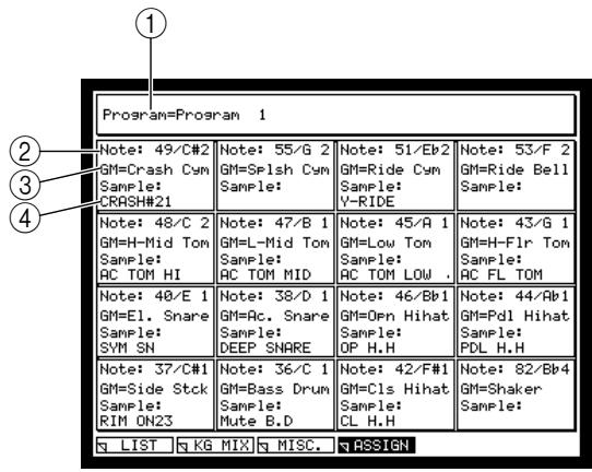
① Program field: Indicates the currently selected program.
② Note field: Specifies the note number that is assigned to this pad number.
③ GM field: Indicates the GM format (GM system level 1) drum/percussion sound that corresponds to the note number selected in (2).
④ Sample field: Specifies the sample that is assigned to this pad number.
Note: Key group programs do not contain pad assign settings. Thus, the [F4] key function (Assign) will not be displayed if a key group program is selected in the List page.
If you strike the pads when a key group program is selected, note data will be output according to the default pad assign settings (these are referred to as the "global pad assign" settings).
Editing sound parameters
The programs of the MPC4000 let you edit various sound parameters such as filter, envelope, and LFO for each key group/note number.
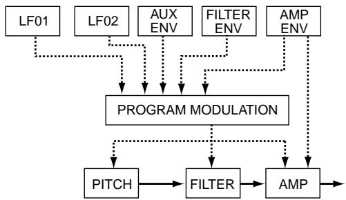
Here's how to edit parameters such as amp envelope, filter, filter envelope, and LFO1.
1. In the Program mode Key Group page, press the [F4] key (EDIT 1).
The Edit 1 page will appear, in which you can edit the filter and envelope settings for each key group/notes number.
![AKAI MPC4000 - In the Program mode Key Group page, press the [F4] key (EDIT 1). - 1](/content/2025/01/152367/images/aae895f1989733ab8fd28fe59b7fd7c9e5581edcb676c1a091a6e038b521d461.jpg)
① Note/Kg field: Selects the key group/notes number that you will edit.
② Edit field: Selects the key group editing method.
③ Zone field: Selects the zone (1-4) that will be displayed in (4).
④ Zone Sample field: Displays the name of the sample that is assigned to the zone you selected in (3).
(5) PITCH block: Specifies the tuning of the key group/note number.
⑥ FILTER block: Edits the filter type, cutoff frequency, resonance, and filter envelope parameters.
⑦ AMP block: Edits the level, output destination, effect send, and amp envelope parameters of the key group/ note number.
2. Move the cursor to the Edit field, and select one of the following editing methods.
ONE: Only the key group selected in the Kg field will be edited.
ALL: The absolute values of all key groups will be changed simultaneously.
ADD: The values of all key groups will be adjusted simultaneously, relative to their current value.
Hint: Normally, you will probably want to select ALL first, and make approximate settings for all key groups. Then select ONE to make fine adjustments to individual key groups/pad numbers. To apply an overall boost or cut to a certain parameter after you have made fine adjustments, select ADD.
3. If you have set the Edit field to ONE, move the cursor to the Kg/Pad field, and select the key group/pad number that you want to edit.
Hint: It is convenient to use the BLOCK CURSOR [▲] / [▼] keys to move between blocks.
4. Move the cursor to the right half of the AMP block, and edit the amp envelope parameters.
In the AMP block you can set the following amp envelope parameters.
Attack field: Specifies the attack time of the envelope (the time from when the key is pressed until the maximum level is reached).
Decay field: Specifies the decay time of the envelope (the time from when the attack time ends until the sustain level is reached).
Sustain field: Specifies the sustain level of the envelope (the level that will be maintained as long as you continue holding the key or pad).
Release field: Specifies the release time of the envelope (the time from when the key is released until the level reaches zero).
Attack hold: Selects whether to begin the decay when the loop start point of the sample is reached (ON), or to follow the settings of the envelope (OFF).
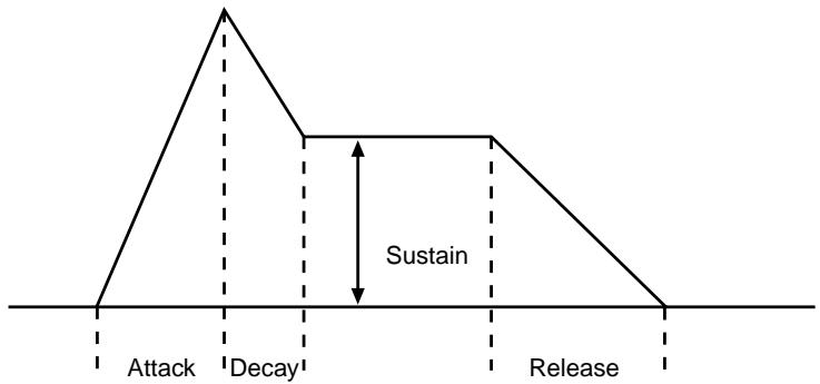
5. Move the cursor to the FILTER block, and edit the filter parameters.
In the FILTER block you can set the following filter parameters.
Type field: Selects the type of filter. (For details on each type, refer to the reference manual.)
Cutoff freq field: Specifies the cutoff frequency of the filter.
Resonance field: Selects the resonance of the filter.
Hint: The Cutoff freq/Resonance field display will change depending on the filter type.
Attenuation field: Adjusts the level after the signal has passed through the filter. You can use this to make adjustments when an excessively high resonance setting has caused the level to be overloaded.
R1-R4 fields: Set the rate 1-rate 4 parameters of the envelope.
L1-L4 fields: Set the level 1-level 4 parameters of the envelope.
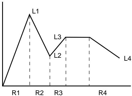
Reference field: Specifies the reference level (0-100) of the envelope. This value is shown as a horizontal dotted line in the displayed envelope.
When the envelope reaches the level you specify here, an offset will be applied to the entire envelope so that the filter cutoff matches the setting of the Cutoff freq field.
The operation of the envelope will change as follows, according to the Reference value and the L3 value.
Reference=0: The envelope levels will be added relative to the setting of the Cutoff freq field.
Reference=L3: The filter cutoff will match the value of the Cutoff freq field when the envelope reaches the sustain level.
Reference=100: The filter cutoff will match the value of the Cutoff freq field when the envelope reaches the maximum level.
- To apply the filter envelope to the filter, press the [WINDOW] key when the cursor is located in the FILTER block.
Note: Be aware that unlike the amp envelope, simply setting values for the filter envelope is not enough to produce an effect. In order to use the filter envelope, you must make settings in the Program Modulation popup window to specify the modulation source, modulation destination, and modulation depth.
The Program Modulation popup window will appear. In this window you can select the modulation source, modulation destination, and modulation depth for each of the modulation routes (a maximum of 64) that the program can use.
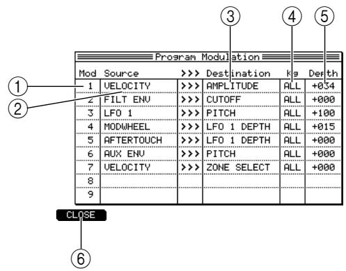
① Mod field: Indicates the modulation number (1-64). You can move the cursor to this field and turn the [JOG] dial to scroll the list.
② Source field: Selects the modulation source (modulation wheel, envelope, velocity, LFO1, LFO2, etc.).
③ Destination field: Selects the modulation destination parameter (AMPLITUDE, PAN, PITCH, etc.).
④ Note/Kg field: Selects the key group/notes number whose depth (5) you will set. If you select ALL, you can set the depth of all key groups at once.
⑤ Depth field: Specifies the depth of modulation.
(6) [F1] key (CLOSE): Closes the popup window and returns to the previous page.
- Move the cursor to an empty Source field, and select FILTER ENV as the modulation source.
- Move the cursor to the Destination field, and select CUTOFF as the modulation destination.
-
Make sure that the Note/Kg field is set to ALL, move the cursor to the Depth field, and set the modulation depth.
-
When you have finished making settings, press the [WINDOW] key.
You will return to the Edit 1 page. Now you can use the filter envelope to control the cutoff. If necessary, readjust the parameters of the FILTER block while you play the sound.
In this way when you want to use the envelope or LFO etc. to modulate the pitch, filter (tone color), or amp (volume), simply access the Program Modulation popup window and specify the Source (modulation source), Destination (modulation destination), and Depth (modulation depth). A wide range of parameters are available as the modulation source and modulation destination. By taking advantage of these, you can create highly sophisticated sounds.
Note: The PITCH block Tune field is the same parameter as the identically-named field of the Pitch page. Also, the AMP block Level, Out, FX Send, and Send fields are respectively the same parameters as Level, Out, FX, and Send fields of the Key Group Mix page.
- Press the [F4] key (EDIT 2).
The Edit 2 page will appear, where you can set the LFO and AUX envelope parameters.
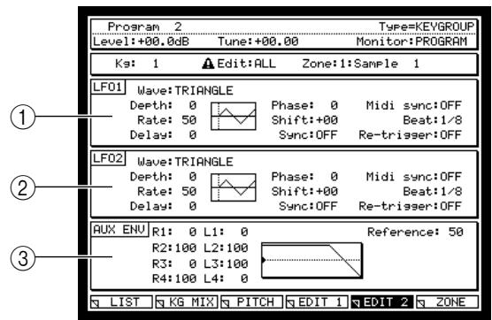
① LFO1 block: Sets the LFO1 parameters (rate, depth, delay, etc.).
LFO2 block: Sets the LFO2 parameters (rate, depth, delay, etc.).
③ AUX ENV block: Sets the AUX envelope parameters.
- Move the cursor to the LFO1 blink, and edit the LFO1 parameters.
The fields of the LFO1 block edit the following parameters.
Wave field: Selects the LFO waveform from TRIANGLE (triangle wave), SINE (sine wave), SQUARE (square wave), SAW UP (upward sawtooth wave), SAW DOWN (downward sawtooth wave), and RANDOM (random change).
Depth field: Specifies the LFO output level.
Rate field: Specifies the LFO frequency.
Delay field: Specifies the time from when you press a key until the LFO is applied.
Phase field: Adjusts the location at which the LFO cycle will begin. The vertical dotted line will move according to this setting.
Shift field: Offsets the LFO level upward or downward. The horizontal line will move according to this setting.
Sync field: Specifies whether the LFOs of each voice in the same program will be synchronized with each other.
MIDI sync field: Specifies whether the LFO frequency will be synchronized to MIDI clock messages received from an external device.
Beat field: Specifies the LFO cycle when MIDI sync is ON.
Re-trigger field: Specifies whether the waveform will re-start from the beginning at each note-on.
- When you have finished editing the LFO1 parameters, press the [WINDOW] key with the cursor located in the LFO1 block.
The Program Modulation popup window will appear.
Note: In order to use LFO1, you must set the modulation source, modulation destination, and modulation depth in the Program Modulation popup window. Be aware that simply editing the settings of the LFO1 block parameters will not produce an effect.
- Move the cursor to an empty Source field, and select LFO1 as the modulation source.
- Move the cursor to the Destination field located at the right, and select PITCH as the modulation destination.
- Move the cursor to the, and specify the depth of modulation.
- Press the [WINDOW] key to return to the Edit 2 page.
Now LFO1 will apply vibrato to the sample. If necessary, re-adjust the parameters of the LFO1 block while you play the sound.
Note: The Depth field of the LFO1 block corresponds to the LFO1 output level, and the Depth field of the Program Modulation popup window corresponds to the sensitivity of the modulation destination. This means that if the Depth field is set to zero for either of these, LFO1 will not produce any effect.
Using zones
In the preceding pages, we created a program by assigning a sample only to zone 1 of a key group/note number. However, the programs of the MPC4000 actually allow you to use four zones for each key group/note number.
This section explains how you can assign a sample to zone 2 of each key group/note number, and use velocity to switch between zones 1 and 2.
- Record the samples that you want to assign to zone 2. (You can either record new samples into memory, or load them from a storage device.)
For details on how to record or load samples, refer to chapter 8.
- In the Key Group Mix page, Pitch page, or Edit 1/2 page, press the [F6] key (ZONE).
The Zone page will appear. In this page you can assign samples to zones 1-4 and edit parameters for each zone.
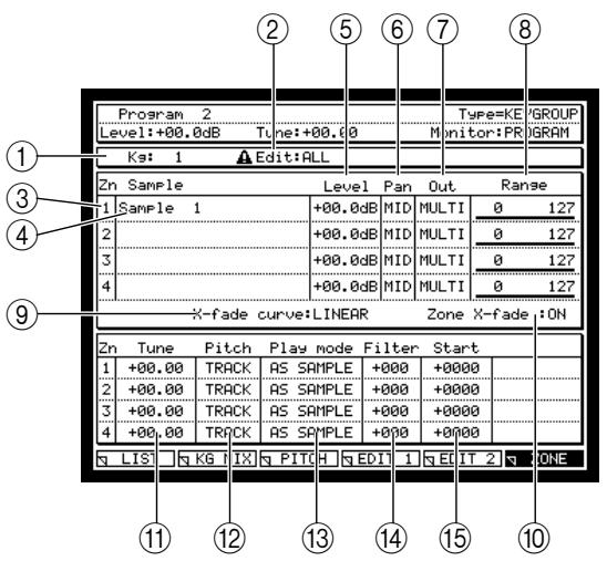
① Note/Kg field: Selects the key group/notes number that you will edit.
② Edit field: Selects the editing method for the key group.
③ Zone field: Indicates the zone numbers.
(4) Sample field: Selects the sample that will be assigned to each zone.
Note: The sample that you select in the Key Group Mix page will always be assigned to zone 1 of the corresponding key group/pad number. You must use this field to assign samples to zones 2-4.
⑤ Level field: Specifies a relative adjustment to the level of each zone.
⑥ Pan field: Specifies a relative adjustment to the pan of each zone when stereo playback is used.
⑦ Out field: Specifies the output destination of each zone. If you select MULTI, the settings of the multi will be used.
(8) Range field: Specifies the note range of each zone when you use a specific modulation source to switch the zone that will sound.
(9) X-fade curve field: Selects the curve of change that will be used when crossfading between zones is turned on.
Zone X-fade field: Specifies whether crossfading between zones will occur when you change zones.
① Tune field: Specifies a relative adjustment to the tuning of each zone.
Pitch field: Specifies whether the pitch of the sample assigned to each zone will rise or fall according to the keyboard position (TRACK) or will be the same pitch regardless of the note you play (CONS).
⑬ Play mode field: Selects one of the following playback methods for the sample assigned to each zone. ONE SHOT: The sample will play from the start point to the end point when you press the key once. NO LOOP: The sample will play from the start point to the end point without looping. If you release the pad (key) during this time, the playback will stop at that point.
LOOP: When you press the pad (key), the sample will begin playing from the start point, and will continue looping as long as you hold down the pad (key). When you release the pad (key), the sample will play to the end point and then stop.
NOTE OFF: The sample will play in one-shot mode when a note-off message is received.
④ Filter field: Specifies a relative adjustment to the filter cutoff of each zone.
⑤ Start field: Specifies a relative adjustment to the start point for the sample of each zone.
- Move the cursor to the Note/Kg field, and select the key group/note number to which you want to add a sample.
- Move the cursor to the Sample field of zone 2, and select a sample.
This will assign a sample to zone 2. The settings of the Key Group Mix, Pitch, and Edit 1/2 pages are common to all zones, so you do not need to make them again.
- If necessary, edit the other parameters in the Zone page to make fine adjustments to the level, pan, and filter offset for each zone.
Note: Remember that the values of the fields in the Zone page (except for Output, Range, Pitch, Play mode) are relative adjustments. The values common to the entire key group/pad number can be edited in the Key Group Mix, Pitch, and Edit 1/2 pages.
- In the same way, assign a new sample to zone 2 of the other key groups/note numbers.
- When you have finished assigning all the desired samples, move the cursor to the Range field of zone 1, and set the value to 000-063.
-
Move the cursor to the Range field of zone 2, and set the value to 064-127.
-
Leave the cursor at the Range field, and press the [WINDOW] key.
The Program Modulation popup window will appear.
- Move the cursor to an empty Source field, and select VELOCITY as the modulation source.
- Move the cursor to the Destination field at the right, and select ZONE SELECT as the modulation destination.
- Move the cursor to the Depth field, and set the value to 100.
- Press the [WINDOW] key.
You will return to the Zone page. Now you can use velocity to switch between zones for all key groups/pad numbers. Make fine adjustments to the Range field while striking the pads or playing your MIDI keyboard.
Other settings
Here's how to make settings that affect the entire program, such as MIDI transpose and bend range.
- In the List page, press the [F3] key (MISC.).
The MISC. page will appear. In this page you can make settings that are common to the entire program.
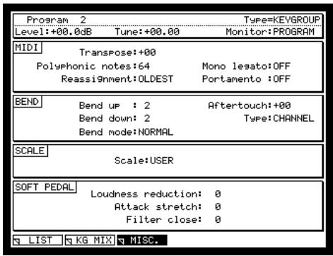
① MIDI block: Here you can set the transposition for the entire program, the polyphony, the processing mode that will be used when the MPC4000 runs out of voices, and portamento on/off.
② BEND block: Here you can make settings for pitch bend and aftertouch.
③ SCALE block: Here you can select the scale (equal-tempered, Werckmeister, etc.) used by the program.
④ SOFT PEDAL block: Here you can specify what will occur when you press the soft pedal.
- Move the cursor to the MIDI block, and set the following fields.
Transpose field: Specify the transpose value for the program. This value affects only the MIDI notes that are received; it does not affect the pitch of the samples.
Polyphonic notes field: Specify the number of notes that the program will be able to play.
Reassignment field: As the processing mode that will be used when you have used up the available polyphony, select either QUIET (notes will be turned off starting with the note whose level is lowest) or OLDEST (notes will be turned off starting with the oldest note).
Mono legato field: Specify what will happen when you play two keys legato. If you select OFF, both notes will play normally (polyphonically). If you select PITCH, the program will be in mono mode (you will not be able to play chords); playing two keys legato will cause only the pitch to change without triggering the second note.
Portamento field: Switch portamento on/off.
- Move the cursor to the BEND block, and set the following fields.
Bend up field: Specify the amount of pitch change (in semitones) that will occur when you move the pitch bend controller all the way away from yourself.
Bend down field: Specify the amount of pitch change (in semitones) that will occur when you move the pitch bend controller all the way toward yourself.
Bend mode field: As the mode of operation that will occur when pitch bend messages are received, select either NORMAL (pitch bend will be received even while the note is sounding) or HELD (pitch bend will be received before the note sounds, but not while the note is sounding).
Aftertouch field: Adjust the depth to which aftertouch (pressure) will modulate the pitch.
Type field: As the type of aftertouch, select either CHANNEL (channel pressure) or POLY (key pressure).
Saving or loading programs
The following pages explain how to save or load programs (or samples and programs) to and from a storage device.
Saving programs
Here's how you can save one program or multiple programs (or samples and programs) from memory to an internal or external storage device. When you turn off the power, all programs and samples in the MPC4000 will be lost, so you must use the Save procedure described here to save your programs if you want to keep them.
1. Press the [SAVE] key.
The Save page will appear.
- Move the cursor to the Type field, and turn the [JOG] dial to select SAVE PROGRAMs.
A display like the following will appear.
![AKAI MPC4000 - Press the [SAVE] key. - 1](/content/2025/01/152367/images/9d7f4613a86e54f73c86ac0008f0c1acd545e0ea0b0e971a668e5823341709f7.jpg)
① Disk information: Indicates the storage device that is currently selected for operations.
② Type field: Selects the type of data that will be saved.
③ Disk field: Selects the save-destination storage device.
Save field: Indicates the folder within the save-destination storage device.
⑤ File list block: Shows the folder hierarchy within the selected storage device.
⑥ Tag field: This field lets you tag individual programs. Use this when you want to store the tagged programs in a single operation. Move the cursor to this field, and turn the [JOG] dial to switch the tags on/off.
⑦ Program list field: Lists the names and types of the programs currently in memory. Newly created programs or programs that you have edited after they were last loaded or saved will be indicated by a * symbol in front of their name.
Data size: Indicates the size of the program data.
- If you want to save a single program, move the cursor to the program list field, and select the desired program.
- If you want to save multiple programs in a single operation, move the cursor to the Tag field, and assign a tag to each program you want to save.
- Move the cursor to the Disk field, and turn the [JOG] dial to access the Disk List popup window. In this popup window you can select the save-destination storage device.
![AKAI MPC4000 - Press the [SAVE] key. - 2](/content/2025/01/152367/images/43b72d266365485258be84c8375ca6b111687632edf91005fc089845c950b1cf.jpg)
① Media field: Indicates the type of the storage device.
② Name field: Indicates the volume name of the storage device.
③ Device field: Indicates how the storage device is connected.
④ Free field: Indicates the amount of free space on the storage device.
- Move the cursor to the storage device on which you want to save the data, and press the [F6] key (SELECT).
That storage device will be selected, and the popup window will close.
- Move the cursor to the save-destination folder in the file list block.
Use the CURSOR[ \triangleleft ] keys to move upward or downward in the folder hierarchy, and use the CURSOR[ \triangleup ] keys to select a folder within the same level of the hierarchy. When you select the save-destination folder, that folder name will be displayed in the Save field.
Hint: By pressing the [F3] key (NEW) you can create a new folder in the current level. The file you save will be saved within the folder that is selected in the left side of the file list (the level displayed at the right).
To save a single program
- If you are saving a single program, make sure that the desired program is selected in the program list field, and then press the [F6] key (DO IT).
The Save a Program popup window will appear.
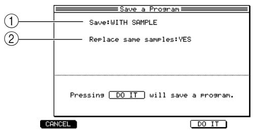
① Save field: Specifies whether only the program will be saved, or the samples and program will be saved.
② Replace same samples field: Specifies what will occur if the save destination contains an identically-named sample file.
- Move the cursor to the Save field, and select one of the following save methods.
WITH SAMPLES PROGRAM ONLY: All samples used by that program will be saved along with the program.
PROGRAM ONLY: Only the program will be saved.
NEW&MODIFIED: Only the samples marked by an * symbol will be saved along with the program.
Note: If you select NO or NEW&MODIFIED, please be aware that it will not be possible to load that program unless the corresponding folder of the storage device contains the appropriate sample files.
- If you selected WITH SAMPLES for the SAVE field, move the cursor to the Replace same samples field, and specify whether identically-named sample files in the storage destination will be overwritten when the data is saved (YES), or not overwritten (NO).
- Press the [F6] key (DO IT).
The program file (or program file and sample files) will be saved in the folder you specified.
To save multiple programs
- If you want to save multiple programs in a single operation, press the [F5] key (MULTIPLE) after step 5.
The Save Multiple Programs popup window will appear, allowing you to select the programs that will be saved.
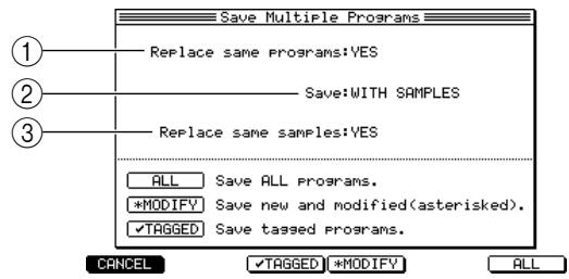
① Replace same programs field: Specifies what will occur if the save destination contains an identically-named program file.
② Save field: Specifies whether only the programs will be saved, or the samples will be saved along with the programs.
③ Replace same samples: Specifies what will occur if the save destination contains an identically-named sample file.
- As necessary, move the cursor to the various fields of the Save Multiple Programs popup window, and make the desired settings.
- Press one of the following function keys to specify the programs that you want to save.
[F1] key (CANCEL): Cancel the Save operation and close the popup window.
[F3] key (TAGGED): Save only the tagged programs (or programs and samples), and close the popup window.
[F4] key (MODIFY): Save only the programs (or programs and samples) marked by the * symbol, and close the popup window.
[F6] key (ALL): Save all programs (or programs and samples), and close the popup window.
Loading a program
Here's how to load a program (or a program and samples) from a storage device into the MPC4000's internal memory.
- Press the [LOAD] key.
The Load page will appear. In this page you can load files that were saved on a storage device.
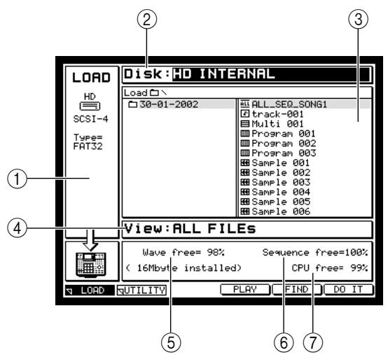
① Disk information: Shows information on the storage device that is currently selected for operations.
② Disk field: Selects the storage device from which the data will be loaded.
③ File list block: Displays the internal hierarchy of the selected storage device.
④ View field: Selects the type of file that will be shown in the file list block.
⑤ Wave free field: Indicates the amount of free memory for the MPC4000's sampler section.
⑥ Sequence free field: Indicates the amount of free memory for the MPC4000's sequencer section.
⑦ CPU free field: Indicates the amount of free space in the MPC4000's data management memory.
- Move the cursor to the Disk field, and turn the [JOG] dial to display the Disk List popup window.
- Move the cursor to the storage device from which you want to load data, and press the [F6] key (SELECT).
The storage device at which you placed the cursor will be selected as the source for loading.
- Move the cursor to the View field, and select PROGRAM FILEs as the type of file.
Files other than program files will be hidden.
- Move the cursor to the desired file in the file list block.
Use the CURSOR[ \triangleleft ] /[▶] keys to move upward or downward in the folder hierarchy, and use the CURSOR[ \triangleleft ] /[▼] keys to select a folder or file within the same level of the hierarchy.
- Press the [F6] key (DO IT).
The Load a program popup window will appear.
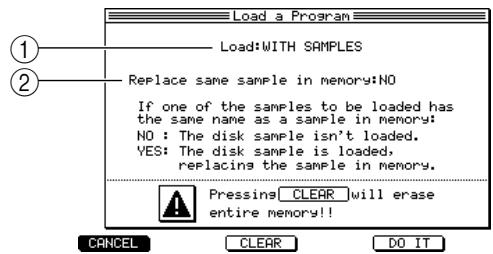
① Load file: Specifies whether the samples used by the program will also be loaded.
② Replace same sample in memory field: Specifies what will occur if memory already contains an identically-named sample.
- Move the cursor to the Load field, and select one of the following loading methods.
NO SAMPLE: Only the program will be loaded.
WITH SAMPLE: The program and the necessary samples will be loaded.
Note: If you selected NO SAMPLE, be aware that the program cannot be played correctly unless the memory of the MPC4000 contains the necessary samples.
-
If you selected WITH SAMPLES in step 7, move the cursor to the Replace same... field. Specify whether any identically-named sample existing in memory will be overwritten by the loaded file (YES) or whether such a file will not be loaded (NO).
-
Once again press the [F6] key (DO IT).
The program (or program and samples) will be loaded.
Hint: If desired, you can erase all programs and samples from memory before you load a program. To do this, press the [F3] key (CLEAR) while the Load a program popup window is displayed.
10 Using storage devices
This chapter explains operations for internal and external storage devices.
The file structure of the MPC4000
The various types of data in the internal memory of the MPC4000 (sequences, songs, multis, samples, programs) can be saved as separate files on an internal or external storage device.
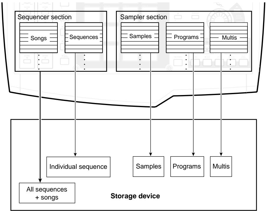
Here are the different types of file that can be saved on an internal or external storage device, and the symbols that indicate each type of file.
- All sequences + songs (ALL ALL symbol)
- Individual sequence (MID MID symbol)
- Multi (Multi Multi symbol)
- Program (III PROGRAM PROGRAM symbol)
- Sample(SAMPLE SAMPLE symbol)
The procedures for saving and loading the above files are described in the corresponding sections of the manual. Please refer to the appropriate page.
File operations for a storage device
Here's how to delete a file that was stored on a storage device.
Deleting a file
Here's how to delete a file from a storage device.
- Press the [SAVE] key or [LOAD] key, and then press the [F2] key (UTILITY).
The Utility page will appear, where you can perform file operations for a storage device.
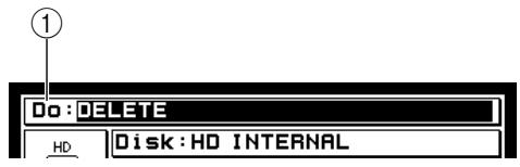
① Do field: Selects the operation that you want to use.
- Make sure that the Do field reads DELETE.
If the Do field reads DELETE, you can delete a file from the storage device. If a different operation is selected, turn the [JOG] dial to select DELETE.
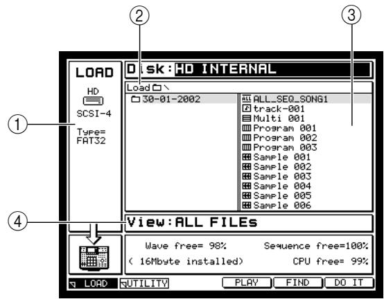
① Disk information: Displays various information on the storage device that is currently selected for operations.
② Disk field: Selects the storage device that contains the file you want to delete.
③ File list block: Displays the internal hierarchical structure of the storage device.
④ View field: Selects the type of file that will be displayed.
- Move the cursor to the Disk field, and turn the [JOG] dial to access the Disk List popup window. In this popup window you can select the storage device that contains the file you want to delete.
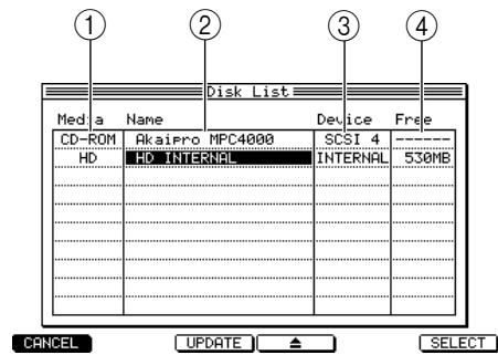
① Media field: Indicates the type of storage device.
② Name field: Indicates the name of the storage device.
③ Device field: Indicates how the storage device is connected.
(4) Free field: Indicates the free space on the storage device.
- Move the cursor to the storage device that contains the file you want to delete, and press the [F6] key (SELECT).
The storage device will be selected, and the popup window will close. The file list block will show the contents of that storage device.
- Move the cursor to the file list, and select the file that you want to delete.
Use the CURSOR [] / [] keys to move upward or downward between levels, and use the CURSOR [] / [] keys to select a folder within the same level.
Hint: If you select a file type in the View field, all other files will be hidden.
- Press the [F6] key (DO IT).
The specified file will be deleted.
Hint: A file that you delete cannot be recovered. Use this command with caution.
Finding a file
Here's how you can search for a file saved on a storage device by specifying a string of characters or a type of file.
- Press the [LOAD] key to access the Load page, and select the storage device that you want to search as the target of operations.
- Press the [F5] key (FIND).
The Find File popup window will appear. In this popup window you can specify a character string and file type to search for a desired file on a storage device.
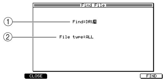
① Find field: Input a character string contained in the file name you want to find.
② File type field: Select the type of file that you want to find.
-
Move the cursor to the Find field, and turn the [JOG] dial to input the character string you want to find.
-
Move the cursor to the File type field, and turn the [JOG] dial to select the type of file you want to find.
-
Press the [F6] key (FIND) to execute.
When the search is completed, the Found Files popup window will appear, displaying the search results.
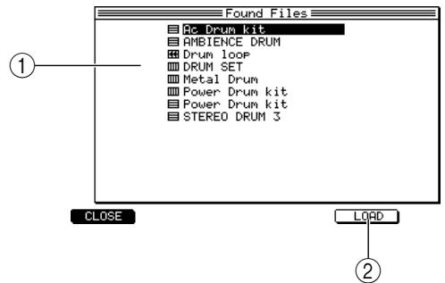
① File list: Displays a list of the search results.
② [F5] key (LOAD): Loads the selected file.
- Use the CURSOR [Δ] / [] keys to select the desired file from the search results, and press the [F5] key (LOAD).
If you want to load another file, repeat this step.
- To close the popup window, press the [F1] key (CLOSE).
Formatting a storage device
Before you can use an internal or external storage device with the MPC4000, you must format (physical format) that device. Here's how to format a storage device.
- Press the [SAVE] key or [LOAD] key, and then press the [F2] key (UTILITY).
The disk utility page will appear.
- Move the cursor to the Do field, and turn the [JOG] dial to select "FULL FORMAT."
In this page you can select one of the following three types of formatting.
FULL FORMAT
A physical format will be performed. Select this method if you are using the storage device with the MPC4000 for the first time.
- QUICK FORMAT
A logical format will be performed. Select this method if you want to initialize a storage device that you have already been using with the MPC4000.
- WIPE VOLUME
All files will be deleted from the currently selected volume of the storage device.
If you selected FULL FORMAT, the display will change as follows. Use the disk list to select the storage device that you want to format.
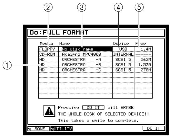
① Disk list: Here you can select the storage device that will be formatted.
② Media field: Indicates the type of each storage device.
③ Name field: Indicates the name of each storage device.
④ Device field: Indicates how each storage device is connected.
⑤ Free field: Indicates the free space on each storage device.
- Move the cursor to the disk list, and select the storage device that you want to format.
- To execute the format operation, press the [F6] key (DO IT).
A physical format will be executed. Once formatting has been completed, you will be able to use that storage device with the MPC4000.
Note: When you format a device, any data that had been stored on that device will be lost forever. Perform this operation with care to avoid erasing any important files.
The time required for formatting will depend on the size and type of the storage device. Large device such as hard disks may take a very long time to format.
Hint: If the storage device connected to the MPC4000 has been divided into partitions, executing the WIPE VOLUME command will erase only the files from the currently selected volume.
11 Using Q-LINK
This chapter explains the Q-LINK function, which lets you use the knobs and sliders of the MPC4000 to control the internal sampler in realtime.
About Q-LINK
Q-LINK is a function that lets you use the four knobs and two sliders in the Q-LINK section of the panel to control the parameters of the internal sampler.
For each knob/slider, you can select the type of event (internal sampler level, pan, filter cutoff, LFO rate etc.) that you want to control.
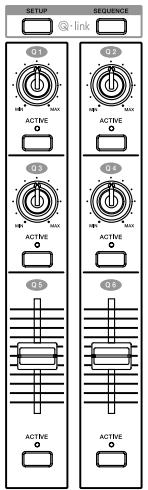
The slider/knob settings are stored in the multi. If you want to keep your settings, you must save the multi in internal memory into an external storage device. (For the save procedure, refer to p.??.)
You can also use "Q-LINK sequence," a unique function found only on the MPC4000. This lets you program Q-LINK knob/slider movements in sixteen steps, and play them back repeatedly along with the sequencer.


STEP1

2


4

5

6

6


·16
By using Q-LINK sequence, you can vary the tone or volume of the internal sampler in synchronization with the tempo of the sequencer. Q-LINK sequence settings are stored in the currently selected sequence, so you can use them as part of the sequence or song.
Hint: Q-LINK sequence records the knob/sliders settings, not the actual parameter changes. This means that the element that is controlled will change according to the parameters that are assigned when the Q-LINK sequence is played.
If you want to keep your Q-LINK sequence settings, you must save the corresponding sequence on an external storage device. (For the save procedure, refer to p.38.)
Assigning parameters to knobs and sliders
Here's how the parameter you want to control can be assigned to a knob or slider of the Q-LINK section.
1. Press the Q-LINK section [SETUP] key.
The Q-LINK setup page will appear. In this page you can assign events to the Q-LINK knobs and sliders.
The knobs and sliders have separate pages. As necessary, move between these pages by pressing the [F1] key (to set knobs) or the [F2] key (to set sliders).
![AKAI MPC4000 - Press the Q-LINK section [SETUP] key. - 1](/content/2025/01/152367/images/276ab7cf55d42a82ebad282910f91a197c4c827a6c6c4135a1a7e158db9b152a.jpg)
![AKAI MPC4000 - Press the Q-LINK section [SETUP] key. - 2](/content/2025/01/152367/images/11a97454cf8d782bf7a7585dd3bbc04ce8ddc5f12ea8719fe0e4299c76e98e4c.jpg)
① Multi field: Selects the multi for which you want to make Q-LINK settings.
② PART/FX field: When you operate a knob/slider, this setting specifies whether the program assigned to a part of the multi will be controlled (PART) or an effect parameter will be controlled (FX). The selectable content of the field at the right will depend on whether you choose PART or FX.
③ Assign field: Selects the type of parameter that will be controlled by the knob or slider. If you selected PART in (2), you can select program parameters. If you selected FX, you can select effect parameters.
④ Type field: Selects how the value will change when you operate the knob or slider.
⑤ Range field: Specifies the amount of change that will occur when you operate the knob or slider.
[6] [F1] key (KNOB): Accesses the Q-LINK setup knob page.
[2] [F2] key (SLIDER): Accesses the Q-LINK setup slider page.
- Move the cursor to the Multi field, and turn the [JOG] dial to select the multi for which you want to make settings.
Q-LINK settings are stored as part of the multi. Thus, you must first use the Multi field to select the multi for which you want to make settings.
- Move the cursor to the Part/FX field for the knob or slider whose settings you want to make, and turn the [JOG] dial to specify whether you will control a part (PART) or an effect (FX).
- Press the right cursor key, and select a part number if you selected PART, or an effect number if you selected FX.
- Move the cursor to the Assign field, and select the parameter that you want to control from the knob or slider.
The parameters that can be selected will depend on whether you have selected PART or FX.
If you selected PARTYou can select any parameter that is available as a program modulation destination.
If you selected FXYou can select effect parameters of the corresponding effect.
- Move the cursor to the Type field, and turn the [JOG] dial to select one of the following two ways in which the value will be controlled.
OFFSET
The value will be adjusted in the positive or negative direction, relative to the existing setting of the parameter.
The 12 o'clock position in the case of a knob, or the center position in the case of a slider, will correspond to the existing setting of the parameter.
REPLACE
The value will change according to the movement of the knob or slider, regardless of the existing setting of the parameter.
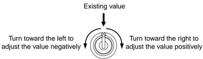
In the case of REPLACE
In the case of OFFSET
The value will change from minimum to maximum, regardless of the existing value
Note: If you select OFFSET, moving the knob/slider in the negative direction will have no effect if the existing setting is zero. Likewise, moving the knob/slider in the positive direction will have no effect if the existing setting is the maximum.
- Move the cursor to the Range field, and turn the [JOG] dial to set the amount of change that can occur.
The Range field specifies the minimum and maximum values that can be controlled by the knob or slider. If the Type field is set to OFFSET, you can adjust this in a range of -50-0-50. If it is set to REPLACE, the range will be 0-100.
- When you have finished making settings, save the multi as necessary.
When you turn the ACTIVE key of a knob/slider on (LED lit) and operate that knob/slider, the sound will change according to the Q-LINK settings you made.
Using Q-LINK sequence
Q-LINK sequence is a function that lets you program knob/slider movements in sixteen steps, and play back the movements automatically in synchronization with a sequence or song. This lets you create rhythmic changes in volume that are synchronized to the tempo of a sequence or song, or create rapid tonal changes that would be impossible to perform manually.
- Press the Q-LINK section [SEQUENCE] key.
The Q-LINK sequence page will appear. Separate pages are provided for the knobs and the sliders. As necessary, press the [F1] key (for knobs) or [F2] key (for sliders) to switch pages while you make settings.
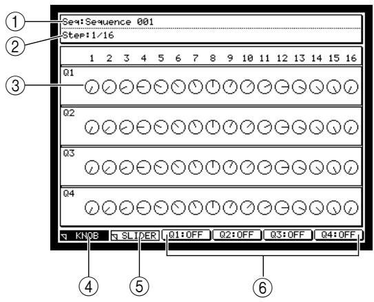
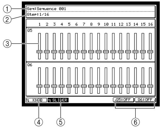
① Seq (sequence) field: Selects the sequence in which you will register the Q-LINK sequence settings.
② Step field: Specifies the length of each step.
③ Setting field: Registers the movements of the knobs or sliders.
(4) [F1] key (KNOB): Accesses the Q-LINK sequence knob page.
[5] [F2] key (SLIDER): Accesses the Q-LINK sequence slider page.
[6] [F3]-[F6] keys (Q1-Q4:ON/OFF): Switches Q-LINK sequence on/off for each knob or slider.
- Move the cursor to the Seq field, and turn the [JOG] dial to select the sequence for which you want to make settings.
Q-LINK sequence settings are saved as part of the sequence. The name of the selected sequence will be displayed in the Seq field.
- Move the cursor to the Step field, and turn the [JOG] dial to specify the length of each step.
For example, setting this to 1/64 will produce extremely rapid change with four steps per 16th note. If you set this to 1/16, each step will correspond to a 16th note.
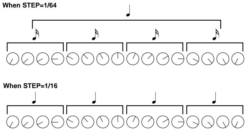
- In the setting field, move the cursor to the step of the knob or slider that you want to set, and move the knob or slider to specify the value for that step.
The display will indicate the position of the knob or slider.
Note: A Q-LINK sequence does not record the parameter values of the event, but simply the movements of the knob or slider. This means that when you play back, the result will depend on the output destination and event type that are assigned to the Q-LINK knob or slider.
- When you have finished making settings, save the sequence as necessary.
- To reproduce the Q-LINK sequence, press the [Q-LINK SEQUENCE] key. The [Q-LINK SEQUENCE] LED will light, and the Q-LINK sequence will be
- To turn a knob or slider on/off individually, press the Q-LINK section [SEQUENCE] key to access the Q-LINK sequence page, and use the [F3]-[F6] keys to switch the knob or slider on/off. Even if the [Q-LINK SEQUENCE] key is on, the movements of a knob/slider will not be output if the corresponding [F3]-[F6] key is turned off.
- Start the sequence/song. The knob/slider movements specified for that sequence will be reproduced.
- If you want to manually operate a knob or slider while the sequence/song is playing, turn on the [ACTIVE] key of that knob or slider. When you turn on the [ACTIVE] key, the movements specified by the Q-LINK sequence will be disabled, and the movements of the knob or slider will take priority.
12 MIDI and synchronization operations
This chapter explains how to make MIDI-related settings, and how to synchronize the MPC4000 with an external device.
MIDI event transmission and reception
The sequencer, sampler, and pad sections of the MPC4000 use MIDI events to communicate internally. When the MPC4000 is in the default state, the MIDI events that are input from the [MIDI IN I] connector and [MIDI IN II] connector and the MIDI events generated by the pads are sent to the sequencer section. When you strike the pads or play a connected MIDI keyboard, MIDI events will be sent to the output destination that is selected for the corresponding track, letting you play sampler programs or external MIDI sound modules.
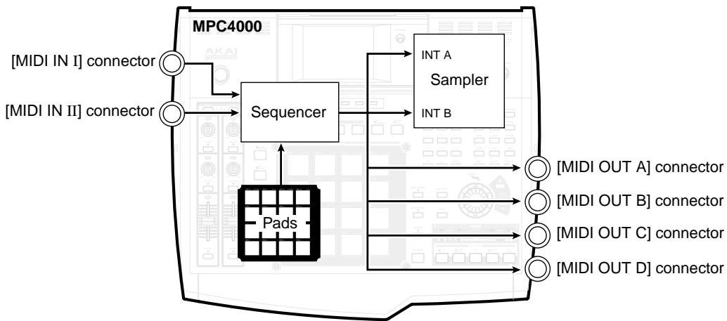
However, you are free to change the way in which MIDI events are routed inside the MPC4000. For example, you can send the MIDI events generated by the pads to the [MIDI OUT A] connector, or send the MIDI events received at the [MIDI IN I] connector directly to the sampler section. In either case, you can directly play an external MIDI sound module or the internal sampler, regardless of the track output destination that is currently selected.
Changing the MIDI event routing
You can change the routing of the MIDI events that are received at the [MIDI IN I] and [MIDI IN II] connectors, and the MIDI events that are generated by the pads.
1. Press the [MIDI] key.
The MIDI mode Routing page will appear, where you can change the MIDI routing.
![AKAI MPC4000 - Press the [MIDI] key. - 1](/content/2025/01/152367/images/e87dc0cd8b9fda12ade59abc9b909e48558d0a02ba93f54153fef8bbaf49fea8.jpg)
① Routing field: Displays the current routing.
② MIDI in I field: Specifies the destination of the MIDI events that are input from the [MIDI IN I] connector.
③ MIDI in II field: Specifies the destination of the MIDI events that are input from the [MIDI IN II] connector.
④ Drum pad field: Specifies the destination of the MIDI events that are generated by the pads.
2. Move the cursor to the field whose routing you want to change.
3. Turn the [JOG] dial to select the MIDI event output destination.
When you change the setting, the MIDI event routing will change, and the routing field will display the new routing. You can choose the following output destinations.
MIDI in-I.....INT-A/SEQUENCER
MIDI in-II.....INT-B/SEQUENCER
Drum pad.....INT-A/SEQUENCER/MIDI OUT-A
![AKAI MPC4000 - Turn the [JOG] dial to select the MIDI event output destination. - 1](/content/2025/01/152367/images/f6b787dd158018a5cd1030df68c46d972eb49ed1cc1ee271da0a9c9c8474f47b.jpg)
If you select INT-A/INT-B
MIDI events will be sent through the internal virtual MIDI port to the various parts. In this case, you will need to set the MIDI transmit channel of the pads or your MIDI keyboard to match the MIDI receive channel of the part you want to play.
If you select SEQUENCER (default setting)
MIDI events will be sent to the tracks of the sequencer. In this case, the MIDI channel will automatically be converted according to the output destination that is selected for the track, so you do not need to be concerned about the MIDI transmit channel of the pads or your MIDI keyboard.
If you select MIDI OUT-A (pads only)
MIDI events will be sent to the [MIDI OUT-A] connector. In this case, you will need to set the MIDI transmit channel of the pads to match the MIDI receive channel of the MIDI sound module you want to play.
Hint: For details on how to set the MIDI transmit channel of the pads, refer to the PDF reference manual.
Filtering the incoming MIDI events
You can apply filtering to the MIDI events that are input from the [MIDI IN I]/[MIDI IN II] connectors to exclude unwanted events.
1. Press the [MIDI] key, and then press the [F2] key.
The MIDI mode Filter page will appear.
![AKAI MPC4000 - Press the [MIDI] key, and then press the [F2] key. - 1](/content/2025/01/152367/images/1c23f4baf4c42257f9e8639f58d9d2da459ff61d14505913ddc4e429d98bc760.jpg)
① MIDI In field: Selects the [MIDI IN] connector whose MIDI events will be filtered.
② Filter field: Switches MIDI filtering on/off.
③ Event type field: Indicates the various types of MIDI event.
④ MIDI channel field: Indicates MIDI channels 1-16.
(5) ALL field: Use this to change the settings of all MIDI channels in a single operation.
2. Move the cursor to the MIDI in field, and turn the [JOG] dial to select the connector (I or II) whose MIDI messages you want to filter.
The display will switch to show the settings of the connector you selected.
3. Move the cursor to the Filter field, and turn the [JOG] dial to turn it On.
- Move the cursor to the Event type field, and select the MIDI event that you want to exclude.
- Move the cursor to the desired channel, and turn the [JOG] dial to change the symbol to . The event you selected in step 4 will be filtered out for MIDI channels with this symbol.
Hint: By moving the cursor to the ALL field and turning the [JOG] dial, you can switch filtering on/off for all MIDI channels.
Monitoring MIDI events
The MPC4000 lets you monitor the state of the MIDI events being transmitted or received from the MIDI connectors. When monitoring MIDI events, you can either view a list of events for a specific channel, or view a graphic display for the events of all channels.
Viewing an event list for a specific channel
You can select a MIDI connector and MIDI channel, and view a list of the MIDI events that are transmitted or received on that channel.
- Press the [MIDI] key, and then press the [F4] key (EVENT) button.
The MIDI mode Event page will appear.
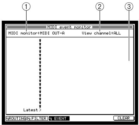
① MIDI monitor field: Selects the MIDI connector that you will monitor.
② View channel field: Selects the MIDI channel that you will monitor.
③ Monitor field: Displays the MIDI events that are being transmitted or received.
- Move the cursor to the MIDI monitor field, and turn the [JOG] dial to select the MIDI connector whose MIDI events you want to view as a list.
- Move the cursor to the View channel field, and turn the [JOG] dial to select 1-16 or ALL as the MIDI channel whose events you want to view.
When MIDI events are received, the events of the selected MIDI channel will be displayed.
Hint: By selecting ALL as the setting of this field, you can monitor all MIDI channels for the connector you selected in step 2.
- To clear the list, press the [F6] key (CLEAR button).
- When you are finished monitoring, press a different mode key to switch pages.
Synchronized operation with other devices
The MPC4000 can use timing and location data such as MIDI clock, MTC, or SMPTE to operate in synchronization with other devices. Here's how to synchronize the MPC4000 and an external device.
Synchronizing the MPC4000 to an external device
Here's how you can use a sequencer or other external device as the synchronization master, and synchronize the MPC4000 to it.
- Connect the MPC4000 and the external device as shown in the diagram below.
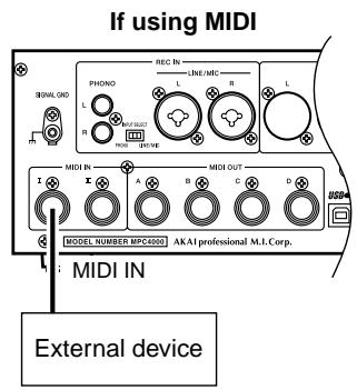
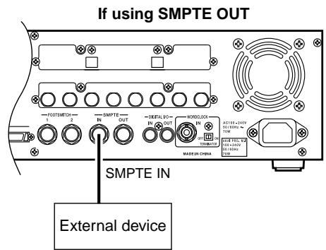
- Access the main page, move the cursor to the Sync field, and press the [WINDOW] key.
The Sync In/Sync Out window will appear. In this window you can specify how the MPC4000 will transmit or receive synchronization signals.
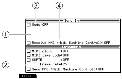
① Sync In window: Specifies the synchronization signal that the MPC4000 will receive.
② Sync Out window: Specifies the synchronization signal that the MPC4000 will transmit.
③ Mode field: Selects the type of synchronization signal that will be received, and the connector at which it will be received.
Receive MMC field: Switches MIDI Machine Control reception on/off.
- Move the cursor to the Mode field, and turn the [JOG] dial to select one of the following as the synchronization signal that the MPC4000 will receive.
The display will change according to the synchronization signal you select.
■ MIDI CLOCK
MIDI Clock will be used for synchronization.
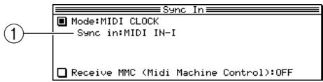
■ MIDI TIME CODE
MTC (MIDI Time Code) will be used for synchronization.
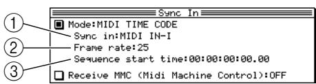
① Sync in field: Selects the connector at which MIDI Clock will be received.
① Sync in field: Selects the connector at which MTC will be received.
② Frame rate field: Specifies the MTC time code frame rate (the number of frames per second).
③ Sequence start time field: Specifies the time code location that will correspond to the beginning of the sequence/song, in hours/minutes/seconds Frames/subframes.
■ SMPTE
SMPTE signals will be used for synchronization.
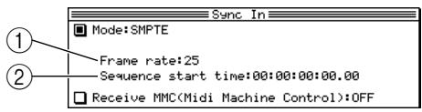
① Frame rate field: Specifies the SMPTE time code frame rate (the number of frames per second).
② Sequence start time field: Specifies the time code location that will correspond to the beginning of the sequence/song, in hours/minutes/seconds/frames/subframes.
- If you selected MIDI clock or MTC, move the cursor to the Sync in field, and turn the [JOG] dial to select the MIDI connector at which MIDI clock or MTC will be received.
If you selected MIDI clock, you must make sure that the time signature of the MPC4000 sequence/song matches the time signature of the external device. If it does not match, locate operations cannot be performed accurately. Also in this case, the tempo you specified on the MPC4000 for the sequence/song will have no effect.
- If you selected MTC or SMPTE, move the cursor to the Frame rate field, and use the [JOG] dial to set the MPC4000's frame rate to match the frame rate of the external device.
If the frame rate does not match, synchronized operation will not occur correctly.
- If you are synchronizing to MTC or SMPTE, move the cursor to the Sequence start field, and specify the desired starting location of the sequence/song.
The Sequence start time field specifies the offset value used to match the starting time of the MPC4000 sequence/song with the time code of the external device.
Note: You can set the offset time in a range of 00:00:00:00.00-23:59:59:29.99. However, it is not possible to synchronize across the zero location with an external device.
- When you have finished making settings, press the [F1] key (CLOSE) to close the window.
- Make sure that the cursor is located at the Sync field, and turn the [JOG] dial to switch the setting ON.
The settings of the Sync In/Sync Out window will take effect when the Sync field is ON. In this state, the MPC4000 will synchronize with an external device.
- If you want a sequence to play back in synchronization with an external device, select the desired sequence in the main page.
- If you want a song to play back in synchronization with an external device, press the [SONG] key, and select the desired song.
11. Begin playback on the external device.
The MPC4000 will start playing the currently selected sequence or song in synchronization with the external device. When you perform play/stop/locate operations on the external device, the MPC4000 will follow.
Hint: If the Receive MMC field is on, an MMC-compatible external device can transmit MMC commands to the MPC4000 to operate its transport.
Note: In order for playback to occur in synchronization with an external device, you must also make synchronization settings on the external device. For details, refer to the owner's manual for that external device.
Synchronizing an external device to the MPC4000
Here's how to use the MPC4000 as the synchronization master, so that a sequencer or other external device will synchronize to it.
1. Connect the MPC4000 to your external device as shown in the diagram below.
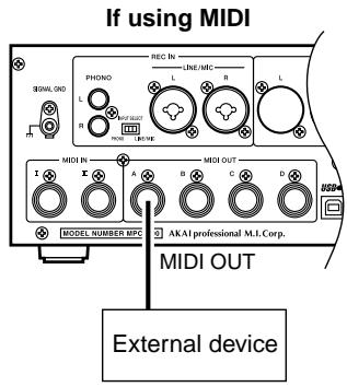

2. Move the cursor to the Sync field, and press the [WINDOW] key.
The Sync In/Out window will appear.
![AKAI MPC4000 - Move the cursor to the Sync field, and press the [WINDOW] key. - 1](/content/2025/01/152367/images/69928316bcfe641f2ec0229b14c3db2953c467d21576922eb2bc35d965d309f7.jpg)
① Sync In window: Specifies the synchronization signal that the MPC4000 will receive.
② Sync Out window: Specifies the synchronization signal that the MPC4000 will transmit.
③ MIDI clock field: Selects the [MIDI OUT] connector from which MIDI Clock will be transmitted.
④MIDI time code field: Selects the [MIDI OUT] connector from which MTC will be transmitted.
⑤ SMPTE field: Switches SMPTE transmission on/off.
⑥ Frame rate field: Specifies the frame rate used when transmitting MTC or SMPTE.
⑦ Send MMC field: Selects the [MIDI OUT] connector from which MMC messages will be transmitted.
Hint: This setting can also be made in the Sync page ([MISC.] key → [F2] key).
- If you want to use MIDI clock as the synchronization signal, move the cursor to the MIDI clock field, and select the MIDI connector from which MIDI clock will be transmitted.
If you select MIDI clock, you must make sure that the time signature of the MPC4000 sequence/song matches the time signature of the external device. If they do not match, locate operations cannot be performed accurately.
- If you want to use MTC as the synchronization signal, move the cursor to the MTC field, and switch the setting ON.
- If you want to use SMPTE as the synchronization signal, move the cursor to the SMPTE field, and switch the setting ON.
- If you are using MTC or SMPTE, move the cursor to the Frame rate field, and use the [JOG] dial to select the frame rate that matches the frame rate of the external device.
If the frame rates do not match, synchronized operation will not occur correctly. - When you have finished making settings, press the [F1] key (CLOSE) to close the window.
-
Make sure that the cursor is located at the Sync field, and turn the [JOG] dial to switch the setting of the field ON.
-
Make settings on the external device so that it will synchronize to the synchronization signal you selected in steps 3-5, and put it in playback-ready mode.
- If you want the external device to synchronize to an MPC4000 sequence, go to the main page and select the sequence that you want to play.
- If you want the external device to synchronize to an MPC4000 song, press the [SONG] key, and then select the song that you want to play.
- Press the [PLAY] key to begin playing the sequence or song.
The external device will operate in synchronization with the MPC4000. If you perform a locate operation on the MPC4000, the external device will change its location accordingly.
Hint: By using the Send MMC field you can use the MPC4000 to control the transport of an external MMC-compatible device.
Note: In order for playback to occur in synchronization with an external device, you must also make synchronization settings on the external device. For details, refer to the owner's manual for that external device.
Specifications
| General | Power supply | 100-240V AC 50/60Hz 70W (27W without options) |
| Dimensions | 526 (W) × 170 (H) × 453 (D) mm (with LCD tilted down) | |
| Weight | 10.5kg (without options) | |
| Display | 320 × 240 dots grey-scale graphical LCD w/back light | |
| Sound Generator | Sampling rate | 44.1kHz, 48kHz, 96kHz |
| Data format | 24/16 bit linear | |
| Sampling time (unexpanded memory) | 180/120 (16/24 bit) seconds mono FS=44.1kHz | |
| 166/110 (16/24 bit) seconds mono FS=48kHz | ||
| 82/53 (16/24 bit) seconds mono FS=96kHz | ||
| 90/60 (16/24 bit) seconds stereo FS=44.1kHz | ||
| 83/55 (16/24 bit) seconds stereo FS=48kHz | ||
| 40/26 (16/24 bit) seconds stereo FS=96kHz | ||
| Memory | 16MB standard, expandable to 512MB | |
| 168-pin DIMM (PC133/PC100, CL2) slot × 2 | ||
| Polyphony | 64 voices | |
| Filter | 2-pole × 3 with resonance | |
| Envelope generators | 3 × Envelope generators (2 multi-stage) | |
| LFO | 2 × Multi-wave | |
| Sequencer | Maximum events | 300,000 notes (equivalent) |
| Resolution | 960 parts per 1/4-note (ppq) | |
| Sequences | 128 | |
| Tracks per sequence | 128 | |
| MIDI output channels | 64 (16 channels × 4 output ports) | |
| Song mode | 128 songs, 250 steps per song | |
| Drum pads | 16 (velocity and pressure sensitive) | |
| Drum pads banks | 6 | |
| Sync modes | MTC, MIDI clock, SMPTE | |
| Inputs/Outputs | Rec In LINE/MIC L/R | 1/4-inch stereo phone/XLR Combo jack, balanced, |
| 1/4-inch phone, Imp. 18kΩ, 24dBu max./XLR, Imp. 6kΩ, 22dBu max. | ||
| Rec In PHONO L/R | RCA phono × 2 with RIAA EQ, -24dBu max. (1kHz) | |
| Main Out L/R | 1/4-inch stereo phone/XLR Combo jack, balanced, | |
| 1/4-inch phone, Imp. 1.7kΩ, 24dBu max./XLR, Imp. 200Ω, 18dBu max. | ||
| Assignable Outs (IB-48P required) | 1/4-inch stereo phone × 8, balanced, Imp. 1.7kΩ, 18dBu max. | |
| Headphone | 1/4-inch stereo phone, 60mW (32Ω) | |
| Digital Input (IB-4D required) | RCA phono × 1, SPDIF | |
| Digital Main Output (IB-4D required) | RCA phono × 1, SPDIF | |
| Word Clock Input (IB-4D required) | BNC × 1 (w/75Ω terminator On/Off) | |
| SMPTE In | 1/4-inch stereo phone, balanced | |
| SMPTE Out | 1/4-inch stereo phone, balanced | |
| Footswitch | 1/4-inch phone × 2 | |
| MIDI Input | 5-pin DIN × 2 | |
| MIDI Output | 5-pin DIN × 4 | |
| SCSI | 50-pin high-pitch SCSI connector × 1 | |
| USB | Host × 1, Slave × 1 (V1.1) | |
| Options | IB-4D | Digital Audio (SPDIF) I/O board |
| IB-4ADT | Adat Interface board (2-in/8-out) | |
| IB-48P | Assignable 8-channel Output Board | |
| Standard accessory | Power Cable | × 1 |
| CD-ROM disc | × 1 | |
| Drive Mounting Kit | × 1 | |
| User Guide | × 1 |
- The specifications are subject to change without the prior notice.
MPC4000 MIDI IMPLEMENTATION CHART (Sequencer section)
Version : V1.0
Date : March 2002
| FUNCTION... | TRANSMITTED | RECOGNISED | REMARKS | |
| BASIC Channel | Default: Changed: | 1-16 1-16 | 1-16 1-16 | |
| MODE | Default: Messages: Altered: | X X **** | X X X | 0 |
| ********** | X | |||
| NOTE NUMBER | True Voice: | 0-127 **** | 0-127 0-127 | |
| VELOCITY | Note ON: Note OFF: | O O | O O | |
| AFTERTOUCH | Key's: Ch's: | O O | O O | |
| PITCH BEND | O | O | ||
| CONTROL CHANGE | 64 0-127 | O O | O O | Converted as note duration Recorded as event |
| PROGRAM CHANGE | True #: | 0-127 **** | 0-127 1-128 | |
| SYSTEM EXCLUSIVE | O | O | MPC4000 ID :61H | |
| SYSTEM Song Pos: COMMON Song Sel: Tune: | O X X | O X X | ||
| SYSTEM Clock: REAL TIME Commands: | O O | O O | ||
| All Sound Off: Reset Controllers: AUX Local ON/OFF: Messages All Notes OFF: Active Sensing: System Reset: | O O O X X X X | O O | ||
Mode 1: OMNI ON, POLY
Mode 2: OMNI ON, MONO
O:YES
Mode 3: OMNI OFF, POLY
Mode 4: OMNI OFF, MONO
X:NO
Version : V1.0
Date: March, 2002
MPC4000 MIDI IMPLEMENTATION CHART (Sound generator section)
| FUNCTION... | TRANSMITTED | RECOGNISED | REMARKS | |
| BASIC Channel | Default: | X | 1-16 | |
| Changed: | X | 1-16 | ||
| MODE | Default: | X | MODE 3 | Multi Mode Program/Sample Mode |
| Messages: | X | MODE 1, 3 | ||
| Altered: | ********** | X | ||
| NOTE NUMBER | True Voice: | X | 0-127 | |
| 0-127 | ||||
| VELOCITY | Note ON: | X | O | |
| Note OFF: | X | O | ||
| AFTER TOUCH | Key's: | X | O | Selectable as KEY or CHANNEL |
| Ch's: | X | O | ||
| PITCH BEND | X | O | ||
| CONTROL CHANGE | 0 | X | O | Bank Select (Multi) Modulation Wheel Volume Pan Sustain Pedal Portamento ON/OFF Soft Pedal Legato Portamento Control Via Program Modulation |
| 1 | X | O | ||
| 7 | X | O | ||
| 10 | X | O | ||
| 64 | X | O | ||
| 65 | X | O | ||
| 67 | X | O | ||
| 68 | X | O | ||
| 84 | X | O | ||
| 0-127 | X | O | ||
| PROGRAM CHANGE | True #: | X********** | O (0-127) | |
| 1-128 | ||||
| SYSTEM EXCLUSIVE | X | O | MPC4000 ID :61H | |
| SYSTEM Song Pos: COMMON Song Sel: Tune: | X | X | ||
| X | X | |||
| X | X | |||
| SYSTEM Clock: REAL TIME Commands: | X | X | ||
| X | X | |||
| All Sound Off: Reset Controllers: | X | O | ||
| X | O | |||
| AUX Local ON/OFF: Messages: Active Sensing: System Reset: | X | X | ||
| X | O | |||
| X | X | |||
| X | X | |||
Mode 1: OMNI ON, POLY
Mode 2: OMNI ON, MONO
O:YES
Mode 3: OMNI OFF, POLY
Mode 4: OMNI OFF, MONO
X:NO
AKAI professional M.I. Corp.

- M4000 MUSIC PRODUCTION CENTER
- AKAI
- PROFESSIONAL
- USER GUIDE
- WARNING
- IMPORTANT NOTICE
- LIMITED SOFTWARE WARRANTY POLICY
- LITHIUM BATTERY
- WARNING: WHEN USING ELECTRIC PRODUCTS, BASIC PRECAUTIONS SHOULD ALWAYS BE FOLLOWED, INCLUDING THE FOLLOWING
- PROTECTING YOURSELF AND THE Z4/Z8
- THIS APPARATUS MUST BE EARTHED
- IMPORTANT
- FCC WARNING
- AVIS POUR LES ACHETEURS CANADIENS DU Z4/Z8
- VENTILATION
- COPYRIGHT NOTICE
- CONTENTS
- 1 PARTS AND THEIR FUNCTIONS 1
- 2 INTRODUCING THE MPC4000 8
- 3 CREATING AND EDITING A SEQUENCE 17
- 4 CREATING AND EDITING A SONG 43
- 5 USING MULTIS AND PARTS 48
- 6 MIXER MODE OPERATIONS 57
- 7 EFFECTS 59
- 8 RECORDING AND EDITING SAMPLES 63
- 9 CREATING AND EDITING PROGRAMS 80
- 10 USING STORAGE DEVICES 95
- 11 USING Q-LINK 99
- 12 MIDI AND SYNCHRONIZATION OPERATIONS 103
- SPECIFICATIONS 109
- 1 PARTS AND THEIR FUNCTIONS
- PARTS AND THEIR FUNCTIONS
- TOP PANEL
- Q-LINK SECTION
- PAD SECTION
- DATA ENTRY SECTION
- MODE SECTION
- CONTROL SECTION
- REAR PANEL
- FRONT PANEL
- AUDIO/MIDI CONNECTIONS
- CONNECTING USB DEVICES
- CONNECTING SCSI DEVICES
- 2 INTRODUCING THE MPC4000
- HOW THE MPC4000 IS STRUCTURED
- SAMPLER SECTION
- SAMPLES
- PROGRAMS
- DRUM PROGRAMS
- KEY GROUP PROGRAMS
- MULTI
- SEQUENCER SECTION
- TRACKS AND SEQUENCES
- SONGS
- PADS 1-16
- PAD BANKS
- ABOUT THE MEMORY OF THE MPC4000
- BASIC OPERATION ON THE MPC4000
- SWITCHING MODES
- ACCESSING A PAGE
- OPERATING THE FUNCTION KEYS
- EDITING A VALUE
- ACCESSING A POPUP WINDOW
- EDITING A NAME
- LOCATING TO A SPECIFIC PLACE
- PLAYING A PROGRAM
- PRESS THE [F5] KEY (SELECT)
- MOVE THE CURSOR TO THE VIEW FIELD IN THE CENTER OF THE DISPLAY, AND USE THE [JOG] DIAL TO SELECT "PROGRAM
- MOVE THE CURSOR TO THE FILE LIST, AND USE THE CURSOR [] /[▼] /[▲] /[►] KEYS TO SELECT THE FILE YOU WANT TO LOAD
- WHEN YOU HAVE SELECTED A PROGRAM FILE, PRESS THE [F6] KEY (DO IT BUTTON)
- 3 CREATING AND EDITING A SEQUENCE
- ABOUT SEQUENCES
- PREPARATIONS FOR CREATING A SEQUENCE
- PRESS THE [MAIN] KEY
- MOVE THE CURSOR TO THE SEQ FIELD, AND TURN THE [JOG] DIAL TO SELECT AN EMPTY SEQUENCE
- MOVE THE CURSOR TO THE BARS FIELD, AND TURN THE [JOG] DIAL
- REALTIME INPUT
- REALTIME-RECORDING A DRUM PROGRAM
- MAKE SURE THAT THE TYPE FIELD IS SET TO DRUM
- MOVE THE CURSOR TO THE OUT1 FIELD, AND TURN THE [JOG] DIAL TO SELECT ONE OF THE FOLLOWING OUTPUT DESTINATIONS FOR THE TRACK
- MOVE THE CURSOR TO THE PART FIELD OR THE CH FIELD, AND TURN THE [JOG] DIAL TO SPECIFY A PART NUMBER (IF YOU SELECTED PART) OR A MIDI CHANNEL (IF YOU SELECTED OUT A-OUT D)
- IF YOU SELECTED PART AS THE OUTPUT DESTINATION, MOVE THE CURSOR TO THE RIGHT OF THE PART FIELD AND SELECT THE DESIRED PART NUMBER. THEN MOVE THE CURSOR TO THE RIGHT AGAIN, SELECT THE DRUM PROGRAM THAT YOU WILL PLAY USING THIS PART
- STRIKE THE PADS, AND MAKE SURE THAT YOU CAN HEAR THE PROGRAM OR MIDI SOUND SOURCE
- MOVE THE CURSOR TO THE TC FIELD, AND TURN THE [JOG] DIAL TO SELECT ONE OF THE FOLLOWING CHOICES AS THE MINIMUM TIMING INTERVAL AT WHICH NOTE EVENTS WILL BE RECORDED IN THE TRACK
- REALTIME-RECORDING A KEY GROUP PROGRAM
- AUTO PUNCH-IN/OUT
- STEP RECORDING
- PRESS THE [F1] KEY (OPTION) TO ACCESS THE STEP EDIT OPTION POPUP WINDOW
- EDITING A TRACK
- USING THE GRAPHIC EDITOR TO EDIT
- EDITING A DRUM-TYPE TRACK
- IN THE MAIN PAGE, SELECT A DRUM-TYPE TRACK AND PRESS THE [SEQ EDIT] KEY TO ACCESS THE SEQUENCE EDIT PAGE
- IF YOU WANT TO CHANGE THE PAD BANK THAT IS SHOWN BY THE GRAPHIC EDITOR, PRESS A PAD BANK [A]-[F] KEY TO VIEW THE CORRESPONDING PAD BANK
- MOVE THE CURSOR TO THE TIMING CORRECT FIELD, AND SPECIFY THE RESOLUTION OF THE TIME RULER
- MOVE THE CURSOR TO EITHER THE MEASURE, BEAT, OR TICK AREA OF THE NOW FIELD, AND MOVE THE VERTICAL MARKER TO THE LOCATION THAT YOU WANT TO EDIT
- USE THE BLOCK CURSOR [Δ] / [] KEYS TO MOVE THE CURSOR INTO THE GRAPHIC EDITOR
- SELECT THE GRID AREA THAT YOU WANT TO EDIT
- TO SELECT A SINGLE GRID LOCATION
- TO SELECT MULTIPLE GRID LOCATIONS
- USE THE [ERASE] KEY OR THE [F2] KEY (MOVE)-[F5] KEY (EDIT) TO ACCESS THE EDITING COMMAND THAT YOU WANT TO USE
- EXECUTE THE EDITING COMMAND
- ABOUT THE EDITING COMMANDS
- [ERASE]KEY
- [F2] KEY (MOVE)
- [F3] KEY (COPY)
- [F4] KEY (CUT)
- [F5] KEY (EDIT)/(PASTE)
- EDIT
- PASTE
- EDITING AN INST TYPE TRACK
- SELECT AN INST TYPE TRACK IN THE MAIN PAGE, AND PRESS THE [SEQ EDIT] KEY
- TO SWITCH THE RANGE OF NOTES SHOWN IN THE GRAPHIC EDITOR, MOVE THE CURSOR INTO THE GRAPHIC EDITOR AND PRESS THE CURSOR [▲]/[▼] KEYS REPEATEDLY TO SCROLL THE PIANO-ROLL UPWARD OR DOWNWARD
- MOVE THE CURSOR TO THE MEASURE, BEAT, OR TICK OF THE NOW FIELD, AND MOVE THE VERTICAL MARKER TO THE BEGINNING OF THE RANGE THAT YOU WANT TO EDIT
- SELECT THE NOTE EVENT THAT YOU WANT TO EDIT
- TO SELECT A SINGLE NOTE
- TO SELECT MULTIPLE NOTES
- USE THE [ERASE] KEY OR [F2] KEY (MOVE)-[F5] KEY (EDIT) TO CHOOSE AN EDITING COMMAND
- EDITING CONTINUOUSLY-VARIABLE EVENTS
- IN THE MAIN PAGE, SELECT THE TRACK THAT YOU WANT TO EDIT, AND PRESS THE [SEQ EDIT] KEY
- MOVE THE CURSOR TO THE VIEW FIELD AND TURN THE [JOG] DIAL TO SELECT THE CONTINUOUSLY-VARIABLE EVENT THAT YOU WANT TO EDIT
- IF YOU SELECTED CONTROL CHANGE OR POLY PRESSURE, PRESS THE CURSOR [▶] KEY TO MOVE THE CURSOR, AND TURN THE [JOG] DIAL TO SELECT THE CONTROL CHANGE NUMBER OR NOTE NUMBER
- ADDING CONTINUOUSLY-VARIABLE EVENTS
- LINEAR
- LOGARITHM
- EXPONENTIAL
- USING THE EVENT LIST
- PRESS THE [STEP EDIT] KEY
- COPYING A TRACK
- DELETING A TRACK
- EDITING A SEQUENCE
- COPYING A SEQUENCE
- DELETING A SEQUENCE
- VIEWING THE PARAMETERS OF ALL TRACKS
- OUT2 PAGE
- PARAMS PAGE
- SAVING AND LOADING A SEQUENCE
- SAVING ALL SEQUENCES/SONGS
- SAVING A SINGLE SEQUENCE
- PRESS THE [SAVE] KEY
- MOVE THE CURSOR TO THE TYPE FIELD, AND TURN THE [JOG] DIAL TO SELECT SAVE SEQUENCE
- LOADING AN ALL FILE (ALL SEQUENCES/SONGS) OR A SINGLE SEQUENCE
- PRESS THE [LOAD] KEY
- IF LOADING A SINGLE SEQUENCE
- IF LOADING AN ALL (ALL SEQUENCES + SONGS) FILE
- TO EXECUTE THE LOAD OPERATION, PRESS THE [F5] KEY
- 4 CREATING AND EDITING A SONG
- ABOUT SONGS
- CREATING A SONG
- EDITING A SONG
- DELETING A SONG
- CONVERTING A SONG INTO A SEQUENCE
- 5 USING MULTIS AND PARTS
- ABOUT PARTS
- SPECIFY THE PART DIRECTLY
- SPECIFY THE PART VIA THE RECEIVE MIDI PORT/MIDI CHANNEL
- ABOUT MULTIS
- EDITING PART PARAMETERS
- ASSIGNING A PROGRAM TO A PART
- PRESS THE [MULTI] KEY, AND THEN PRESS THE [F2] KEY (MIX)
- IF NECESSARY, MOVE THE CURSOR TO THE MULTI FIELD AND TURN THE [JOG] DIAL TO SELECT A MULTI
- MOVE THE CURSOR TO THE PART FIELD, AND TURN THE [JOG] DIAL TO SELECT THE PART WHOSE PARAMETERS YOU WANT TO EDIT
- MOVE THE CURSOR TO THE PROGRAM/TYPE FIELD OF THE PART TO WHICH YOU WANT TO ASSIGN A PROGRAM, AND TURN THE [JOG] DIAL TO ASSIGN THE DESIRED PROGRAM
- ADJUSTING THE MIX PARAMETERS OF A PART
- MOVE THE CURSOR TO THE PART FIELD AND TURN THE [JOG] DIAL TO SELECT THE PART WHOSE SETTINGS YOU WANT TO ADJUST
- MOVE THE CURSOR TO THE FIELD OF THE PARAMETER YOU WANT TO ADJUST, AND TURN THE [JOG] DIAL TO ADJUST THE VALUE
- SETTING THE RECEIVE MIDI PORT/MIDI CHANNEL OF A PART
- PRESS THE [MULTI] KEY, AND THEN PRESS THE [F3] KEY (MIDI)
- MOVE THE CURSOR TO THE PART FIELD, AND TURN THE [JOG] DIAL TO SELECT A PART
- MOVE THE CURSOR TO THE PARAMETER FIELD THAT YOU WANT TO ADJUST, AND TURN THE [JOG] DIAL TO ADJUST THE VALUE
- ADJUSTING THE NOTE RANGE OF A PART
- PRESS THE [MULTI] KEY, AND THEN PRESS THE [F4] KEY (SPAN)
- ADDING OR DELETING A PART
- CREATING A MULTI
- MOVE THE CURSOR TO THE MULTI LIST, AND PRESS THE [WINDOW] KEY
- PRESS THE [F5] KEY (NEW)
- MOVE THE CURSOR TO THE NEW NAME FIELD, AND USE THE [JOG] DIAL TO ASSIGN A NAME TO THE NEWLY CREATED MULTI
- MOVE THE CURSOR TO THE NUMBER OF PARTS FIELD, AND TURN THE [JOG] DIAL TO SPECIFY THE NUMBER OF PARTS THAT YOU WANT TO USE IN THE NEW MULTI
- TO EXECUTE, PRESS THE [F6] KEY (DO IT)
- IN ORDER TO USE THE MULTI YOU CREATED, MOVE THE CURSOR TO THAT MULTI
- COPYING A MULTI
- DELETING A MULTI
- SAVING OR LOADING A MULTI
- SAVING A MULTI
- MOVE THE CURSOR TO THE TYPE FIELD, AND TURN THE [JOG] DIAL TO SELECT SAVE MULTIS
- MOVE THE CURSOR TO THE DISK FIELD AND TURN THE [JOG] DIAL
- MOVE THE CURSOR TO THE STORAGE DEVICE ON WHICH YOU WANT TO STORE THE MULTI, AND PRESS THE [F6] KEY (SELECT)
- MOVE THE CURSOR TO THE DATA LIST, AND USE THE CURSOR [Δ] /[▼] KEYS TO MOVE THE CURSOR TO THE MULTI THAT YOU WANT TO SAVE
- MOVE THE CURSOR TO THE FILE LIST BLOCK, AND SELECT THE FOLDER IN WHICH YOU WANT TO SAVE THE MULTI. USE THE CURSOR [] / [] KEYS TO MOVE UPWARD OR DOWNWARD THROUGH THE FOLDER HIERARCHY, AND THE CURSOR [] / [] KEYS TO SELECT A FOLDER WITHIN THE SAME LEVEL
- PRESS THE [F6] KEY (DO IT)
- LOADING A MULTI
- 6 MIXER MODE OPERATIONS
- ABOUT MIXER MODE
- USING THE PART MIXER
- 7 EFFECTS
- BASIC EFFECT OPERATIONS
- PRESS THE [EFFECT] KEY, AND THEN PRESS THE [F1] KEY (SELECT)
- EDITING THE EFFECT PARAMETERS
- 8 RECORDING AND EDITING SAMPLES
- ABOUT SAMPLES
- RECORDING (SAMPLING) AN EXTERNAL SOURCE
- PREPARATIONS BEFORE RECORDING
- IF YOU WANT TO START RECORDING MANUALLY
- MOVE THE CURSOR TO THE TIME FIELD, AND SET THE RECORDING TIME
- PRESS THE [WINDOW] KEY
- ACTUAL RECORDING
- MAKING VARIOUS SETTINGS FOR A SAMPLE YOU RECORDED
- PRESS THE [F2] KEY (TRIM/LP)
- APPLYING Q-FX AND RESAMPLING
- IF YOU SELECT COMMAND
- IF YOU SELECT EFFECT
- MOVE THE CURSOR TO EACH FIELD OF WINDOW, AND SPECIFY THE DESIRED COMMAND/EFFECT TYPE AND PARAMETER SETTINGS
- IF YOU WANT TO EDIT THE EFFECT PARAMETERS OF FX 1-FX 4, MOVE THE CURSOR TO THE DESIRED EFFECT FIELD, AND PRESS THE [F5] KEY (EDIT)
- TO APPLY Q-FX AND EXECUTE RESAMPLING, PRESS THE [F6] KEY (DO IT)
- USING EDIT COMMANDS TO EDIT A SAMPLE
- TO EXECUTE THE SAMPLE EDIT COMMAND, PRESS THE [F6] KEY (DO IT)
- DIVIDING A SAMPLE
- SPECIFYING THE AREA TO BE DIVIDED
- IN SAMPLE MODE, PRESS THE [F3] KEY (REGION)
- ADJUSTING THE REGION START AND REGION END POINTS
- USING THE DIVIDED SAMPLE TO CREATE A SEQUENCE AND PROGRAM
- PLAYING THE TRACK YOU CREATED
- PRESS THE [MAIN] KEY TO ACCESS THE MAIN PAGE
- SELECT THE SEQUENCE AND TRACK
- PLAY THE PADS
- PRESS THE [PLAY] KEY TO PLAY BACK THE SEQUENCE
- CHANGING THE PITCH OF THE PROGRAM YOU CREATED
- PRESS THE [PROGRAM] KEY, AND THEN PRESS THE [F2] KEY (KG MIX)
- MOVE THE CURSOR TO THE TUNE FIELD, AND ADJUST THE PITCH OF THE PROGRAM
- ADJUSTING THE TEMPO OF THE PHRASE
- IN THE REGION PAGE, MOVE THE CURSOR TO THE SAMPLE FIELD, AND SELECT A SAMPLE
- PRESS THE [F4] KEY (BPM)
- MOVE THE CURSOR TO THE SECTION FIELD, AND SELECT THE SECTION FROM WHICH THE CURRENT TEMPO WILL BE CALCULATED
- MOVE THE CURSOR TO THE BEAT FIELD, AND INPUT THE NUMBER OF BEATS IN THE SECTION YOU SELECTED IN THE SECTION FIELD
- MOVE THE CURSOR TO THE TYPE FIELD, AND SELECT ONE OF THE FOLLOWING TWO CHOICES TO SPECIFY HOW THE TEMPO OF THE SAMPLE WILL BE CHANGED
- TUNE
- STRETCH
- SAVING AND LOADING SAMPLES
- SAVING SAMPLES
- LOADING SAMPLES
- 9 CREATING AND EDITING PROGRAMS
- ABOUT PROGRAMS
- CREATING A NEW PROGRAM
- MOVE THE CURSOR TO THE PROGRAM LIST FIELD, AND PRESS THE [WINDOW] KEY
- ASSIGNING SAMPLES TO A PROGRAM
- ASSIGNING SAMPLES TO A KEY GROUP PROGRAM
- ASSIGNING SAMPLES TO A DRUM PROGRAM
- PRESS THE [F3] KEY (PITCH)
- MOVE THE CURSOR TO OTHER FIELDS, AND MAKE THE DESIRED SETTINGS
- PAD ASSIGNMENTS FOR A DRUM PROGRAM
- EDITING SOUND PARAMETERS
- IN THE PROGRAM MODE KEY GROUP PAGE, PRESS THE [F4] KEY (EDIT 1)
- MOVE THE CURSOR TO THE EDIT FIELD, AND SELECT ONE OF THE FOLLOWING EDITING METHODS
- IF YOU HAVE SET THE EDIT FIELD TO ONE, MOVE THE CURSOR TO THE KG/PAD FIELD, AND SELECT THE KEY GROUP/PAD NUMBER THAT YOU WANT TO EDIT
- MOVE THE CURSOR TO THE RIGHT HALF OF THE AMP BLOCK, AND EDIT THE AMP ENVELOPE PARAMETERS
- MOVE THE CURSOR TO THE FILTER BLOCK, AND EDIT THE FILTER PARAMETERS
- USING ZONES
- OTHER SETTINGS
- SAVING OR LOADING PROGRAMS
- SAVING PROGRAMS
- TO SAVE A SINGLE PROGRAM
- TO SAVE MULTIPLE PROGRAMS
- LOADING A PROGRAM
- 10 USING STORAGE DEVICES
- THE FILE STRUCTURE OF THE MPC4000
- FILE OPERATIONS FOR A STORAGE DEVICE
- DELETING A FILE
- FINDING A FILE
- FORMATTING A STORAGE DEVICE
- 11 USING Q-LINK
- ABOUT Q-LINK
- ASSIGNING PARAMETERS TO KNOBS AND SLIDERS
- PRESS THE Q-LINK SECTION [SETUP] KEY
- OFFSET
- REPLACE
- USING Q-LINK SEQUENCE
- 12 MIDI AND SYNCHRONIZATION OPERATIONS
- MIDI EVENT TRANSMISSION AND RECEPTION
- CHANGING THE MIDI EVENT ROUTING
- PRESS THE [MIDI] KEY
- MOVE THE CURSOR TO THE FIELD WHOSE ROUTING YOU WANT TO CHANGE
- TURN THE [JOG] DIAL TO SELECT THE MIDI EVENT OUTPUT DESTINATION
- IF YOU SELECT INT-A/INT-B
- IF YOU SELECT SEQUENCER (DEFAULT SETTING)
- IF YOU SELECT MIDI OUT-A (PADS ONLY)
- FILTERING THE INCOMING MIDI EVENTS
- PRESS THE [MIDI] KEY, AND THEN PRESS THE [F2] KEY
- MOVE THE CURSOR TO THE MIDI IN FIELD, AND TURN THE [JOG] DIAL TO SELECT THE CONNECTOR (I OR II) WHOSE MIDI MESSAGES YOU WANT TO FILTER
- MOVE THE CURSOR TO THE FILTER FIELD, AND TURN THE [JOG] DIAL TO TURN IT ON
- MONITORING MIDI EVENTS
- VIEWING AN EVENT LIST FOR A SPECIFIC CHANNEL
- SYNCHRONIZED OPERATION WITH OTHER DEVICES
- SYNCHRONIZING THE MPC4000 TO AN EXTERNAL DEVICE
- MIDI CLOCK
- MIDI TIME CODE
- SMPTE
- BEGIN PLAYBACK ON THE EXTERNAL DEVICE
- SYNCHRONIZING AN EXTERNAL DEVICE TO THE MPC4000
- CONNECT THE MPC4000 TO YOUR EXTERNAL DEVICE AS SHOWN IN THE DIAGRAM BELOW
- MOVE THE CURSOR TO THE SYNC FIELD, AND PRESS THE [WINDOW] KEY
- MPC4000 MIDI IMPLEMENTATION CHART (SEQUENCER SECTION)
- AKAI PROFESSIONAL M.I. CORP
Brand : AKAI
Model : MPC4000
Category : Sampler/beat machine