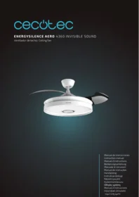
Energysilence Aero 4360 Invisible Sound - Ceiling fan CECOTEC - Free user manual and instructions
Find the device manual for free Energysilence Aero 4360 Invisible Sound CECOTEC in PDF.


| Product type | Ceiling fan |
| Brand | Cecotec |
| Model | Energysilence Aero 4360 Invisible Sound |
| Blade diameter | 132 cm |
| Net weight | 6.5 kg |
| Power supply | 230 V ~ 50 Hz |
| Motor power | 35 W |
| Number of speeds | 6 speeds |
| Motor type | Silent DC motor |
| Main functions | Remote control, timer, summer/winter reverse, night mode |
| Integrated lighting | No |
| Blade material | ABS |
| Care and cleaning | Clean with a soft, dry cloth. Do not use abrasive products. |
| Safety | Automatic shut-off in case of overheating |
| Spare parts available | Yes, blades, remote control, mounting bracket |
| Repairability | Repairability index: 7.5/10 |
| Warranty | 2 years |
Frequently Asked Questions - Energysilence Aero 4360 Invisible Sound CECOTEC
User questions about Energysilence Aero 4360 Invisible Sound CECOTEC
0 question about this device. Answer the ones you know or ask your own.
Ask a new question about this device
Download the instructions for your Ceiling fan in PDF format for free! Find your manual Energysilence Aero 4360 Invisible Sound - CECOTEC and take your electronic device back in hand. On this page are published all the documents necessary for the use of your device. Energysilence Aero 4360 Invisible Sound by CECOTEC.
USER MANUAL Energysilence Aero 4360 Invisible Sound CECOTEC
Safety instructions 9
-
Parts and components 66
-
Before use 66
-
Installation 67
-
Operation 69
-
Cleaning and maintenance 70
-
Technical specifications 70
-
Disposal of old electrical and
electronic appliances 71
-
Technical support and warranty 72
-
Copyright 72
-
SIMPLIFIED EU DECLARATION
OF CONFORMITY. 72
SOMMAIRE
EU01_108466_EnergySilence Aero 4360 Invisible Sound
EN • The coding in this manual is generic and applies to all code variants of the appliance.
Read these instructions thoroughly before using the appliance. Keep this instruction manual for future reference or new users.
- This appliance can be used by children aged 8 years and above and people with reduced physical, sensory, or mental capabilities or lack of experience and knowledge if they have been given supervision or instruction concerning use of the appliance in a safe way and understand the hazards involved. Children must not play with the appliance. Cleaning and user maintenance should not be carried out by unsupervised children.
- Keep a minimum distance of 2.3 cm between the fan blades and the floor.
- Keep a minimum distance of 76 cm between the fan blades and the wall or any other object.
- Make sure the appliance is unplugged from the power supply before cleaning or user maintenance.
- This appliance is designed for domestic use only and is not intended for bars, restaurants, farmhouses, hotels, motels, and offices.
- Make sure that the mains voltage matches the voltage specified on the appliance rating label and that the wall outlet is earthed.
- Do not use the appliance if its cable or housing are damaged, nor after it malfunctions or has been dropped or damaged in any way.
- The appliance must be installed in accordance with national wiring regulations.
- Never insert objects or body parts between the rotating fan blades.
- To reduce the risk of injury, attach the fan directly to
the support structure of the building as indicated in this manual and only use parts and components provided and recommended by Cecotec.
- To avoid risk of electric shock, disconnect the main power supply by turning off the power switches before installing or repairing the fan.
- The electrical wiring must be in accordance with local regulations.
- The wire must be properly earthed to avoid possible accidents.
- The appliance must be installed in accordance with national wiring regulations.
- Never install the fan in a damp or wet room.
- Be careful when near the rotating fan blades.
- To adjust the speed of the fan blades, only use the means for speed control provided by Cecotec.
- Do not bend the blade-attachment system during the installation or cleaning process.
- Cleaning and maintenance must be carried out according to this instruction manual to make sure the appliance works properly. Turn off and unplug the appliance before cleaning it.
- Make sure the fan is not placed close to curtains or other objects it may become entangled with.
- In order to ensure your children's safety, please keep all packaging (plastic bags, boxes, polystyrene, etc.) out of their reach.
- It is recommended that two people install the appliance.
- This appliance is designed for indoor use.
Instructions on batteries
- Battery ingestion can cause burns, soft-tissue perforation,
and death. It can cause severe burns within two hours of the ingestion.
- In case of battery ingestion, please seek medical attention immediately.
- Do not allow children to replace batteries without adult supervision.
- Do not disassemble, open, or damage the batteries.
- Keep the batteries out of the reach of children. Keep especially small batteries out of the reach of children. In case of battery ingestion, please seek medical attention immediately.
- Do not expose batteries to heat or fire. Avoid storage in direct sunlight.
- Do not short-circuit an element or a battery. Do not store batteries in an untidy manner, in a box, or drawer where they can short-circuit each other or be short-circuited by other metal objects.
- Both batteries and cells can leak under extreme conditions. In the event of a battery leak, keep your skin and eyes away from the liquid. If the liquid comes into contact with skin, wash immediately with soap and water. If the liquid gets into the eyes, rinse them immediately with clean water for at least 10 minutes and seek medical attention. Wear gloves to handle the battery and dispose of it immediately in accordance with local regulations.
- Pay attention to the positive (+) and negative (-) marks on the batteries and the remote-control compartment to ensure they are inserted correctly.
- Do not use any batteries that are not designed for use with the appliance.
-
Do not mix batteries of different manufacture, capacity, or size. Supervise children to prevent them from playing with batteries.
-
Always buy recommended batteries.
- Keep the batteries clean and dry. Wipe the battery terminals with a clean, dry cloth if they become dirty.
- Keep the original instruction manual for future reference.
- Whenever possible, remove the batteries when not in use.
INSTRUCTIONS DE SÉCURITÉ
Potencia motor: 35 W DC
Potencia luz: 22 W LED
IPX4
T
https://cecotec.es/es/information/declaration-of-conformity
1. PARTS AND COMPONENTS
Fig. 1
- Canopy
- Downrod and hanging ball
- Long downrod
- Mounting bracket
- Decorative cover
- Motor
- Lamp plate
- Lampshade
- Remote control and receiver
- LED lamp
- Screw kit
NOTE:
The graphics in this manual are schematic representations and may not exactly match the product.
2. BEFORE USE
- This appliance is packaged in a way as to protect it during transport. Take the appliance out of its box and remove all packaging materials. You can keep the original box and other packaging elements in a safe place to prevent damage to the appliance if you need to transport it in the future. If you wish to dispose of the original packaging, make sure all packaging materials are recycled accordingly.
- Make sure all parts and components are included and in good conditions. If there is any piece missing or in bad conditions, contact the official Cecotec Technical Support Service immediately.
Box content
- Fan
- Remote control
- 1.5 V AAA batteries (x2)
- Instruction manual
- Do not remove the serial number of the appliance in order to keep a correct traceability of it in case of assistance.
3. INSTALLATION
Tools required for installation (not included)
- Electrical tape
- Spanner
- Flat-head screwdriver
- Crosshead screwdriver
- Wire cutter pliers
- Stepladder
Installation preparation
- To avoid any damage, make sure that you hang the fan at least 2.3 m from the floor and 76 cm from any walls or obstacles. Fig. 2
- Ensure that the mounting bracket is securely fastened to the building structure and can support the full weight of the fan.
- This fan can be installed on normal ceilings as well as on vaulted or sloped ceilings. The hanging length can be extended by using a longer downrod. Fig. 3
3.1 Mounting bracket installation
Wooden ceiling
Fix the mounting bracket to the wooden ceiling with 4 wood screws (of at least 7-cm thickness). Fig. 4
Concrete ceiling
Drill two holes with a proper depth (an 8-mm diameter) and insert two expansion screws into the holes. Align the holes in the mounting bracket with the screws and secure it with the nuts. Fig. 5
Sloped ceiling
Sloped installation is recommended for vaulted or slanted ceilings.
Maximum 20° tilt. Fig. 3
3.2 Hanging system installation
Fig. 6
If you want the fan to hang lower, remove the hanging ball from the supplied 15 cm (6-inch) downrod in order to use it with a longer downrod (also included).
To remove the hanging ball, loosen the fixing screw and remove the pin and clip. Slide the hanging ball off the downrod and slide it onto the longer downrod (note that the top of the rod has a hole for the fixing screw).
When the hanging ball is in the desired position, insert the pin. Make sure that the pin is aligned with the holes inside the hanging ball and tighten the fixing screw securely.
Note: Wrap the ends of the wires with a piece of electrical tape to hold them together when passing them through the downrod.
Loosen the fixing screws of the motor main body anchor. Then remove the pin and downrod clip (if you have not already done so). Slide the downrod through the canopy.
Pass the electrical wires through the downrod and pull the wires protruding from the top of the downrod end.
Place the downrod into the motor main body anchor and insert the pin and clip previously removed. Tighten the fixing screws securely. Lower the decorative cover onto the motor housing.
Fig. 6 key:
- Electrical wires
- Downrod
- Pin
- Main body
- Canopy
- Decorative cover
- Downrod clip
- Main body anchor
3.3 Electrical connection
To connect the fan and the receiver, follow the steps shown in figure 7.
3.4 Canopy assembly Fig. 8
Lift the canopy to the ceiling to cover the mounting bracket (make sure that the canopy is fixed on the two bracket screws). Turn the canopy to secure it in place. Re-insert the screws and secure them all with a screwdriver.
Once you have secured the mounting bracket to the connection cover, you can hang the fan. Hold the fan firmly with both hands. Slide the downrod through the opening in the mounting bracket and allow the hanging ball to rest on the bracket. Turn the hanging ball until the holes inside align with the tab on the mounting bracket.
Note: Have someone else hold the ladder securely and bring you the fan once you are on the ladder.
3.5 LED lamp assembly Fig. 9
Remove the screws. Attach the LED lamp to the bottom of the fan by inserting the screws into the corresponding holes and screwing them in. Then connect the fan wires to the LED lamp.
Note: During the installation or when the LED lamp is removed, keep the insulation pads intact. Over-tightening the screws may damage them.
3.6 Lampshade assembly Fig. 10
Place the lampshade on the fan body, then turn it until it is fixed in place.
3.7 Connection to the loudspeaker
Enable the Bluetooth on your mobile device and connect to Speaker Light L2.
4. OPERATION
This ceiling fan is operated using the remote control.
Fig. 11
- Power button
- On/off light button
- Winter/summer mode
- Breeze mode
- Fan speed (1-6)
- On/off fan spin button
- Timer (4 or 8 h)
- Light shade change (warm, neutral or cool)
Once you have installed the ceiling fan, you can start using it.
- Press one of the speed buttons to select the desired fan speed. The fan will start to spin, allowing you to adjust the speed of the fan blades to your preference.
- Press the on/off light button (2) to turn the LED light on or off.
- You can change the light shade between neutral, warm or cool by pressing the button corresponding to each shade.
- This ceiling fan has a timer function (7), press the button with the desired time you want the fan to run for.
- Press the winter/summer mode button (3) to reverse the direction of rotation of the blades. In summer mode the blades spin to generate a pleasant breeze, while in winter mode the blades spin to move the cold air towards the ceiling and push the warm air concentrated on the ceiling towards the floor.
- Press the button (4) to select the breeze mode. This mode is designed to provide a refreshing and breeze-like air flow.
- To switch off the fan completely, press the power button (1). If you only want to stop the movement of the blades, but keep the light on, press the on/off fan spin button (6).
WARNING
- If the fan or the light cannot be controlled with the remote control, check if the batteries are in good condition and make good contact. Make sure that the positive and negative poles are correctly positioned and that the batteries are charged.
- If the fan or the light cannot be controlled with the remote control, check if there are other remote-controlled devices in the same area, as they may cause interferences. Also make sure that the buttons on the remote control are not jammed. Please note that this does not affect infrared remote controls.
- Pay attention to the appliance voltage. Too low a voltage may cause the remote control not to work. The technical specifications are indicated in this manual.
- If the remote control is not going to be used for a long time, remove the batteries.
Changing the remote control batteries
The remote control is powered by 2 x 1.5 V AAA batteries.
- Open the battery compartment.
- Insert the batteries into the battery compartment observing the polarity.
- Close the compartment.
5. CLEANING AND MAINTENANCE
- Make sure to disconnect the fan before cleaning it.
- Do not immerse any of the parts of the appliance in water or splash them with any other liquid.
- Do not use solvents or any other chemical products for cleaning.
- Use a soft, dry cloth; use warm water and mild detergent if necessary to clean the surface of the product.
6. TECHNICAL SPECIFICATIONS
Model: EnergySilence Aero 4360 Invisible Sound
Product reference: EU01_108466
Voltage: 230 V\~
Frequency: 50 Hz
Motor power: 35 W DC
Power light: 22 W LED
IPX4
T
| Description | Symbol | Value | Unit |
| Fan maximum flow | F | 115.9 | m^3/min |
| Fan power consumption | P | 29.3 | W |
| Service value | SV | 4.0 | (m^3/min)/W |
| Power consumption on standby mode | P_SB | 0.5 | W |
| Fan noise power level | L_WA | 45 | dB (A) |
| Maximum air speed | C | 2.0 | m/s |
| Service value measurement standard | IEC 60879:2019 | ||
| Contact details to obtain more information | Cecotec Innovaciones SL.Av. Reyes Católicos, No 60, 46910, Alfafar, Valencia, Spain | ||
This product features a light source with an energy efficiency grade E.
The power consumption in standby mode is 0.5 W, using the guidelines of EN 50564:2011 and the European regulations 1275/2008/EC and 801/2013/EC. For this purpose, the appliance is connected to the mains without performing any function, waiting for the standby mode to be activated.
Technical specifications may change without prior notification to improve product quality. Made in China | Designed in Spain
7. DISPOSAL OF OLD ELECTRICAL AND ELECTRONIC APPLIANCES

This symbol indicates that, according to the applicable regulations, the appliance and/or batteries must be disposed of separately from household waste. When this product reaches the end of its shelf life, you should dispose of the cells/batteries/accumulators and take them to a collection point designated by the local authorities.
For detailed information on how to properly dispose of electrical and electronic appliances and/or batteries, consumers should contact their local authorities.
Compliance with the above guidelines will help protecting the environment.
8. TECHNICAL SUPPORT AND WARRANTY
Cecotec shall be liable to the end user or consumer for any lack of conformity that exists at the time of delivery of the product under the terms, conditions and deadlines established by the applicable regulations.
Repairs should be carried out by qualified personnel.
If at any moment you detect any problem with your product or have any doubt, do not hesitate to contact the official Cecotec Technical Support Service at +34 96 321 07 28.
9. COPYRIGHT
The intellectual property rights over the texts in this manual belong to CECOTEC INNOVACIONES, S.L. All rights reserved. The contents of this publication may not, in whole or in part, be reproduced, stored in a retrieval system, transmitted, or distributed by any means (electronic, mechanical, photocopying, recording or similar) without the prior authorization of CECOTEC INNOVACIONES, S.L.
10. SIMPLIFIED EU DECLARATION OF CONFORMITY.
Cecotec Innovaciones hereby declares that this appliance, with model EU01_108466-EnergySilence Aero 4360 Invisible Sound, is in conformity with the EU Directive 2014/53/EU on radio equipment.
The full text of the EU Declaration of Conformity can be found on the following website:
https://cecotec.es/es/information/declaration-of-conformity
1. PIÈCES ET COMPOSANTS
Img. 1
Trocar as pilhas do controlo remoto
https://cecotec.pt/pt/information/declaration-of-conformity
1. ONDERDELEN EN COMPONENTEN
Fig. 1
https://cecotec.es/es/information/declaration-of-conformity
1. PECES I COMPONENTS
Fig. 1

The Ground Truth image displays a single, solid horizontal line. According to Rule 2 (UNDERSCORE & LINE RULES), this is a stylistic or background line, not a placeholder underscore. Therefore, the OCR result must ignore it and output nothing or only meaningful text. The provided OCR content is "____", which consists of four underscores. This is an incorrect interpretation of the line as a placeholder, violating the rule that stylistic lines must be ignored. The OCR has hallucinated underscores where none should exist based on the GT's visual context. Hence, the OCR result is inconsistent with the Ground Truth.
https://cecotec.es/es/information/declaration-of-conformity
تانوکملاو عازجألا
1 للكشل
https://cecotec.es/es/information/declaration-of-conformity
| 1 | 2 | 3 |
| 4 | 5 | 6 |
| 7 | 8 | 9 |
| 10 | 11 |
Fig./Img./Abb./Afb./Rys.1

Fig./Img./Abb./Afb./ Rys. 2

Fig./Img./Abb./Afb./Rys. 3
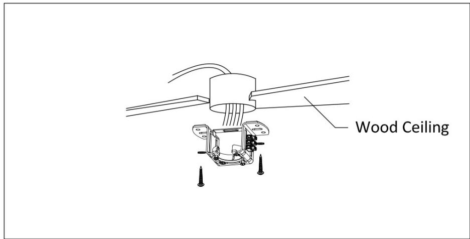
Fig./Img./Abb./Afb./Rys. 4

Fig./Img./Abb./Afb./Rys. 5

Fig./Img./Abb./Afb./Rys. 6

Fig./Img./Abb./Afb./ Rys. 7

Fig./Img./Abb./Afb./ Rys. 8

Fig./Img./Abb./Afb./Rys. 9
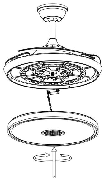
Fig./Img./Abb./Afb./ Rys. 10
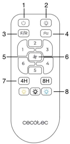
Fig./Img./Abb./Afb./ Rys. 11
www.cecotec.es
- SOMMAIRE
- Instructions on batteries
- INSTRUCTIONS DE SÉCURITÉ
- PARTS AND COMPONENTS
- Fig. 1
- NOTE:
- BEFORE USE
- Box content
- INSTALLATION
- Installation preparation
- Mounting bracket installation
- Wooden ceiling
- Concrete ceiling
- Sloped ceiling
- Hanging system installation
- Fig. 6 key:
- Electrical connection
- Canopy assembly Fig. 8
- LED lamp assembly Fig. 9
- Lampshade assembly Fig. 10
- Connection to the loudspeaker
- OPERATION
- Fig. 11
- WARNING
- Changing the remote control batteries
- CLEANING AND MAINTENANCE
- TECHNICAL SPECIFICATIONS
- DISPOSAL OF OLD ELECTRICAL AND ELECTRONIC APPLIANCES
- TECHNICAL SUPPORT AND WARRANTY
- COPYRIGHT
- SIMPLIFIED EU DECLARATION OF CONFORMITY.
- PIÈCES ET COMPOSANTS
- Trocar as pilhas do controlo remoto
- ONDERDELEN EN COMPONENTEN
- PECES I COMPONENTS
- تانوکملاو عازجألا
Brand : CECOTEC
Model : Energysilence Aero 4360 Invisible Sound
Category : Ceiling fan