
DX5E - Remote control transmitter SPEKTRUM - Free user manual and instructions
Find the device manual for free DX5E SPEKTRUM in PDF.



| Product type | Radio Transmitter |
| Brand | Spektrum |
| Model | DX5e |
| Technology | DSM2 / DSMX (2.4 GHz) |
| Number of channels | 5 channels |
| Transmitter power | 4 AA alkaline batteries (or 4 NiMH 1.2V rechargeable batteries) |
| Minimum alarm voltage | 4.7 V |
| Range | Beyond visual range (reduced range test at 30 paces) |
| Included receiver | AR600 (6 channels, long range) |
| Receiver compatibility | All DSM Spektrum and JR receivers (except limited Park Flyer) |
| Main functions | Digital trims, dual rate (HI/LO 100%/70%), servo reversing, delta wing mixing (elevon), trainer (master/slave), France RF mode |
| Low battery indicator | Audible alarm + flashing LEDs |
| Range test | Reduced mode (press trainer + 4x dual rate) |
| Failsafe safety | SmartSafe: throttle low preset, other channels hold last position |
| Binding | With trainer button and bind plug on receiver |
| Modulation types | DSM2 (22 ms) and DSMX (11 ms 2048) selectable |
| Dimensions and weight | Not specified in the manual |
| Housing material | Not specified |
| Maintenance | Do not lubricate servos, check screws and pushrods regularly |
| Cleaning | Not specified (avoid solvents, use dry soft cloth) |
| Warranty | 6 months (repair or replacement by Horizon Hobby) |
| Repairability | Contact authorized dealer or Horizon Hobby; quote possible for paid repairs |
| Spare parts | Optional accessories (NiMH battery SPM9525, charger SPM9526, trainer cord) |
| Certifications | CE, ETSI (EN 300-328, EN 301 489-1/17), EU compliance |
| General information | Manual available in PDF; support at horizonhobby.com |
Frequently Asked Questions - DX5E SPEKTRUM
User questions about DX5E SPEKTRUM
0 question about this device. Answer the ones you know or ask your own.
Ask a new question about this device
Download the instructions for your Remote control transmitter in PDF format for free! Find your manual DX5E - SPEKTRUM and take your electronic device back in hand. On this page are published all the documents necessary for the use of your device. DX5E by SPEKTRUM.
USER MANUAL DX5E SPEKTRUM
5-Channel Full Range
DSM® 2.4GHz Radio System
5 Kanal DSM 2,4GHz
All instructions, warranties and other collateral documents are subject to change at the sole discretion of Horizon Hobby, Inc. For up-to-date product literature, visit http://www.horizonhobby.com and click on the support tab for this product.
MEANING OF SPECIAL LANGUAGE:
The following terms are used throughout the product literature to indicate various levels of potential harm when operating this product:
NOTICE: Procedures, which if not properly followed, create a possibility of physical property damage AND a little or no possibility of injury.
CAUTION: Procedures, which if not properly followed, create the probability of physical property damage AND a possibility of serious injury.
WARNING: Procedures, which if not properly followed, create the probability of property damage, collateral damage, and serious injury OR create a high probability of superficial injury.

WARNING: Read the ENTIRE instruction manual to become familiar with the features of the product before operating. Failure to operate the product correctly can result in damage to the product, personal property and cause serious injury.
This is a sophisticated hobby product and NOT a toy. It must be operated with caution and common sense and requires some basic mechanical ability. Failure to operate this Product in a safe and responsible manner could result in injury or damage to the product or other property. This product is not intended for use by children without direct adult supervision. Do not attempt disassembly, use with incompatible components or augment product in any way without the approval of Horizon Hobby, Inc. This manual contains instructions for safety, operation and maintenance. It is essential to read and follow all the instructions and warnings in the manual, prior to assembly, setup or use, in order to operate correctly and avoid damage or serious injury.

WARNING AGAINST COUNTERFEIT PRODUCTS
Thank you for purchasing a genuine Spektrum product. Always purchase from a Horizon Hobby, Inc. authorized dealer to ensure authentic high-quality Spektrum product. Horizon Hobby, Inc. disclaims all support and warranty with regards, but not limited to, compatibility and performance of counterfeit products or products claiming compatibility with DSM or Spektrum.
TABLE OF CONTENTS
DSMX. 3
Spektrum DX5e 5-channel DSM Full Range System 4
Transmitter Control Identification. 5
DSM Technology. 6
DSMX Technology. 6
Receiver Compatibility 6
Installing the Transmitter Batteries. 6
Charging Batteries. 7
Digital Trims 8
Low Battery Alarm 8
Trainer. 8
Receiver Installation. 8
Binding. 9
How to Range Test the DX5e 10
AR600 Failsafe 11
How AR600 Failsafe Works. 11
Servo Reversing. 11
HI/LO Rate 11
Elevon/ Delta mixing 11
France RF Setting. 12
Receiver Power System Requirements 12
Tips on Using 2.4GHz Systems 13
General Information 14
Warranty Information. 15
FCC Information 17
Compliance Information for the European Union. 18
Optional Accessories. 18
FRANCE RF SETTING
The DX5e has a France RF setting that complies with French regulations. The France RF setting should only be turned on when operating your transmitter in France outdoors. Please see page 12 for more details.
DSMX
Spektrum launched the 2.4GHz RC revolution with its DSM2 technology. Since then millions of hobbyists the world over have come to embrace 2.4 as the way to fly. Spektrum leads the way yet again with DSMX; the world's first wideband, frequency-agile 2.4GHz signal protocol.
HOW DOES DSMX WORK?
It's a crowded 2.4GHz world out there and every 2.4GHz system faces the same challenges. DSMX better equips you for these challenges by combining the superior data capacity and interference resistance of a wideband signal (like that used in DSM2) with the agility of frequency shifts.
Compared to the wideband signal of DSMX, the narrow band signal of other frequency hopping 2.4 transmitters is more likely to suffer data loss in the event of on-channel interference. Think of it as a river vs. a stream. It takes more interference to dam a river than it does a stream.
As more and more 2.4 transmitters vie for the same number of available channels, there is more interference and more of a risk for data loss. By adding the agility of frequency shifts to the superior interference resistance of a wideband signal, DSMX is far less likely to suffer significant data loss from on-channel interference. The result is quicker connection times and superior response in even the most crowded 2.4GHz environment.
DSMX OPERATIONAL DIFFERENCES
DSMX transmitters and receivers function nearly identically to Spektrum DSM2 systems. Binding, setting the failsafe, recording flight log data, as well as general use of the system is no different than using any current Spektrum system.
FOLLOWING ARE THE OPERATIONAL DIFFERENCES:
Brownout Detection- Not Available on DSMX Receivers
DSM2 receivers feature Brownout Detection that flashes the receiver's LED if a power interruption occurs. While DSMX receivers have QuickConnect and recover instantly from a power interruption, the architecture of DSMX prevents Brownout Detection when operating in DSMX mode.
FLIGHT LOG RECORDING-FADES HIGHER THAN DSM2
Note that DSMX hops through the band while DSM2 finds two quiet channels and remains on those channels. Consequently because DSMX operates on quiet and noisy channels, it's common to have more Antenna Fades than when using DSM2, when used in busy 2.4GHz environments. When taking flight log data readings, the Frames and Hold Data are important and should be used a reference while Fades are insignificant due to the nature of frequency hopping. A 10-minute flight will typically result in less than 50 Frame Losses and no Holds.
JUST HOW GOOD IS DSMX?
In multiple tests, 100 DSMX systems were operated simultaneously for extended periods of time. During these tests each of the 100 systems was monitored in flight and on the ground. In every test not a single case of RF link loss, latency increase or control degradation was experienced or recorded.
IS DSMX COMPATIBLE WITH DSM2?
Yes. DSMX is fully compatible with all DSM2 hardware. In fact, many pilots may find the DSM2 equipment they have now is all they will ever need. Even if a new DSMX transmitter eventually comes along that they really want, all the DSM2 receivers they have now will work with it.
It is important to note, however, that while DSMX is compatible with DSM2, the only way to experience the full benefits of DSMX in a busy 2.4 environment is by pairing a DSMX transmitter with a DSMX receiver.
CAN DSM2 TRANSMITTERS BE UPGRADED TO DSMX?
Yes. DX8 owners can simply download Spektrum AirWare™ v2.0 software from spektrumrc.com and update the firmware using their SD card. DX6i transmitters manufactured after October 2010 can be upgraded using instructions provided on spektrum-rc.com. All other DXDi DSM2 transmitters can be upgraded for $75 by sending them to the Horizon Hobby service center. DSM2 receivers and transmitter modules cannot be upgraded to DSMX.
DOES DSMX HAVE MODELMATCH AND SERVOSYNC?
Yes. DSMX will provide you with these and other exclusive Spektrum advantages you already enjoy with DSM2. Want to know more about DSMX? Visit spektrumrc.com for complete details on this as well as the many other reasons Spektrum is the leader in 2.4.
NOTICE: While DSMX allows you to use more than 40 transmitters simultaneously, when using DSM2 receivers, DSMX receivers in DSM2 mode or transmitters in DSM2 mode, do not use more than 40 transmitters simultaneously.
SPEKTRUM DX5E 5-CHANNEL DSM FULL RANGE SYSTEM
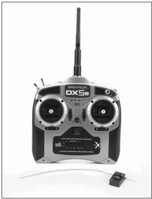
Spektrum DX5e 5-channel system incorporates 2.4GHz DSM technology offering full beyond-the-limits-of-sight range and is ideal for sport-sized electric, gas and glow-powered 5-channel or fewer airplanes. No longer will you have to wait for a frequency pin or be concerned that someone may inadvertently turn on to your same frequency. With Spektrum DSM technology, when you're ready to fly simply turn on, and go flying!
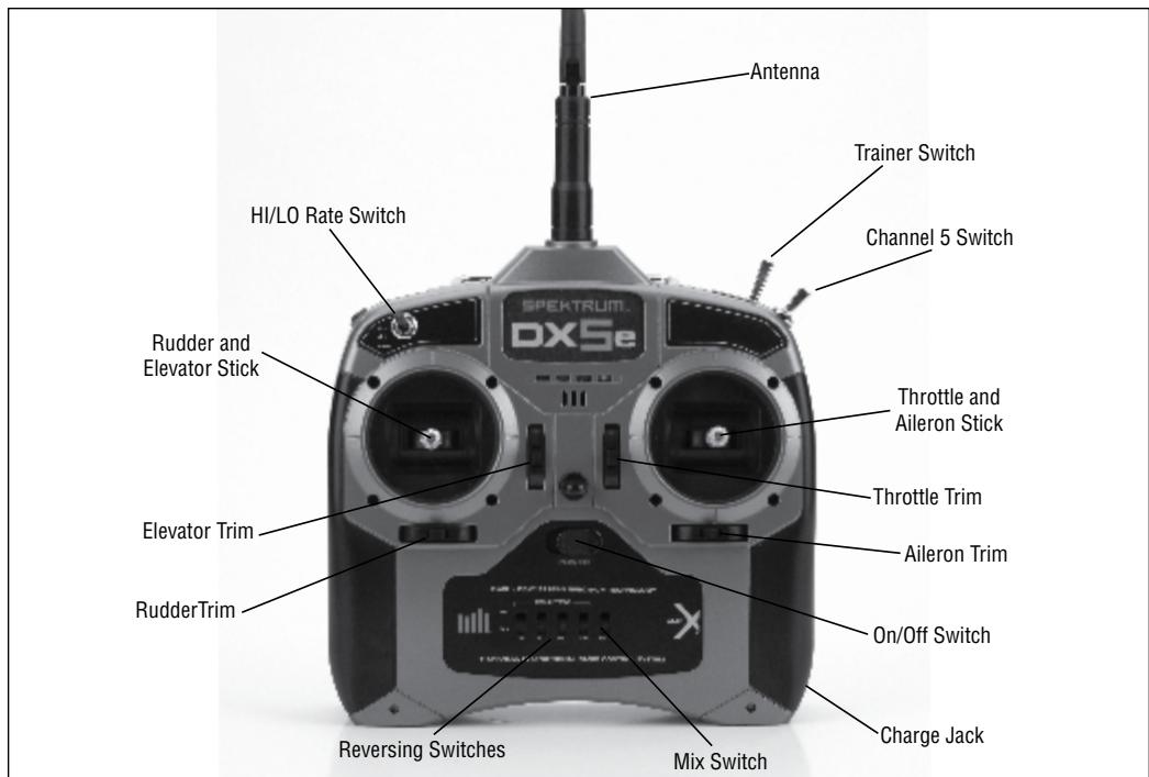
Mode 1
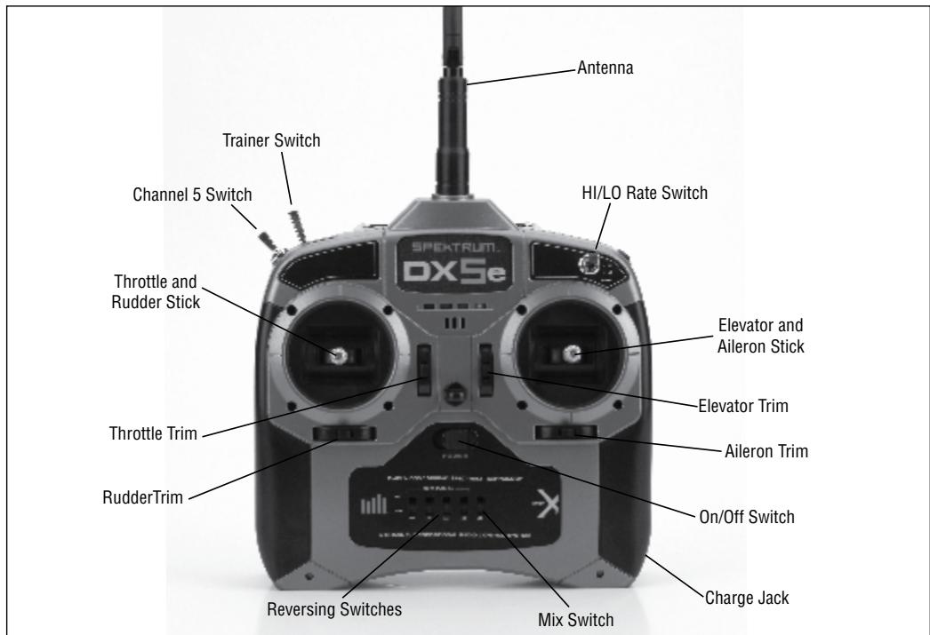
Mode 2
DSM TECHNOLOGY
Your DX5e transmits on the 2.4GHz band and utilizes DSMTM Digital Spread Spectrum Modulation, giving beyond-visual range in all types and sizes of aircraft. Unlike conventional narrow band systems, Spektrum's 2.4GHz digital technology is virtually immune to internal and external radio interference.
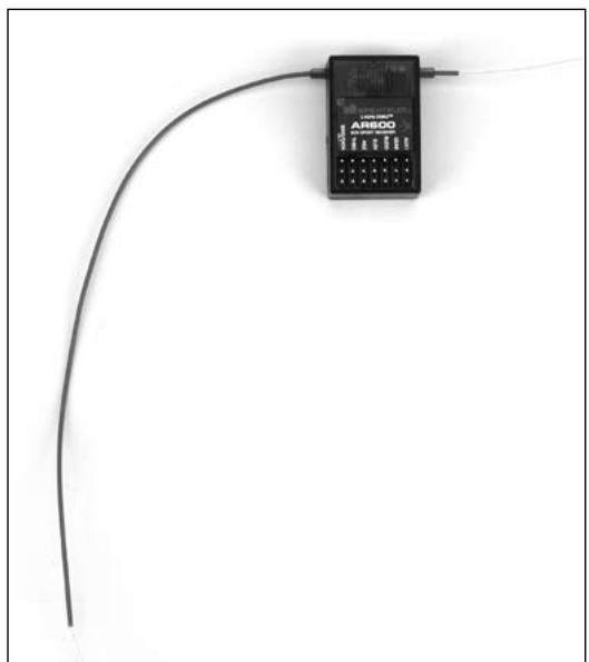
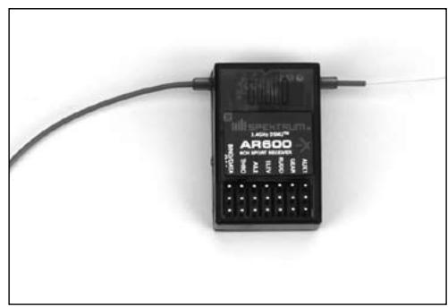
Included with your DX5e is an AR600 6-channel full range sport receiver.
DSMX TECHNOLOGY
DSMX technology can be turned on and off with this transmitter. The default is for DSMX technology to be turned on. When it is on, the transmitter will bind to standard 11ms 2048 DSM2 receivers and DSMX receivers. The only time DSMX technology must be turned off is to bind to high-speed 11ms DSM2 receivers.
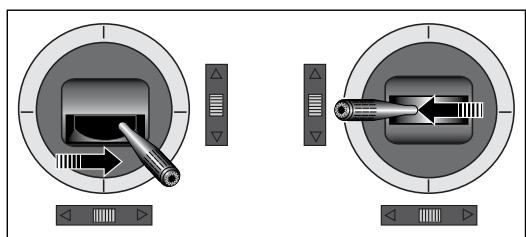
DSMX ON:
Hold the trainer switch and push and hold the Elevator trim button forward. Turn on the transmitter. A series of ascending tones should be heard. Release switches.
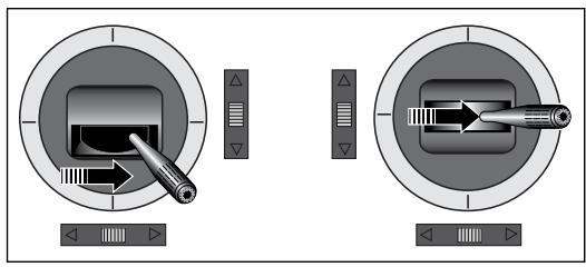
DSM2 ON:
Hold the trainer switch and pull and hold the Elevator trim button backward. Turn on the transmitter. A series of descending tones should be heard. Release switches.
RECEIVERCOMPATIBILITY
The DX5e is compatible with all current Spektrum™ and JR® brands of DSM® aircraft receivers. However, when using the DX5e with one of the Spektrum park flyer receivers, like the AR6115, AR6115e, etc., it is imperative that these receivers be limited to flying Park flyer-type aircraft.
Note: For current receiver compatibility information, go to www.spektrumrc.com http://www.spektrumrc.com.
INSTALLING THE TRANSMITTER BATTERIES
The DX5e requires 4 heavy-duty or alkaline AA batteries.
BATTERY INSTALLATION
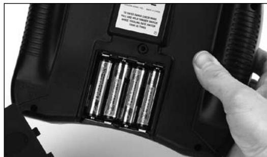
Remove the battery door and install 4 AA batteries. Make sure the polarity of each corresponds with the diagram in the battery holder. Replace the battery door.
Note: Optional NiCd or NiMH 1.2-volt AA rechargeable batteries can also be used. A charge jack is located on the right side of the transmitter for convenient recharging. Spektrum offers rechargeable NiMH batteries, part number SPM9525, and charger, part number SPM9526.
CHARGING BATTERIES
If using rechargeable batteries, it is imperative that you fully charge the batteries prior to each flying session. If you are using the Spektrum NiMH rechargeable batteries (SPM9525) and charger (SPM9526), it is necessary to fully charge the batteries by charging them for 16 hours.
The optional charger (SPM9526) is designed to recharge your batteries at a rate of 150mA . Do not use this charger for equipment other than Spektrum transmitters that use 4-cell battery packs. The charging plug polarity may not be the same and equipment damage can result. During the charging operation, the charger's temperature is slightly elevated. This is normal.
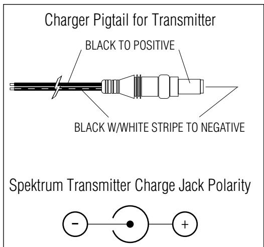
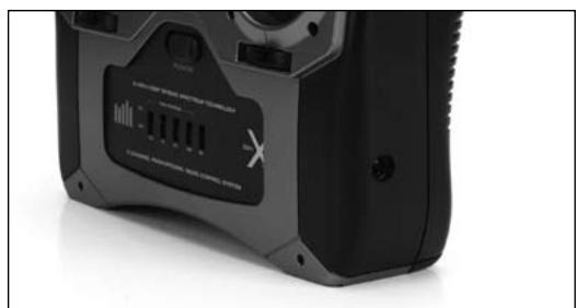
A charging jack is located on the right side of the transmitter. If rechargeable batteries are used they can be conveniently charged without removing them from the transmitter using the charge jack.
CAUTION: Charge only rechargeable batteries. Non-rechargeable batteries may burst causing injury to persons and/or damage to property. Never leave charging batteries unattended.
IMPORTANT: All Spektrum charge jacks are center-pin negative. This is the opposite of many chargers. Before using a charger make sure the connector is center-pin negative. This can be done using a voltmeter. Also unlike conventional radio systems that use 8 cells to power the transmitter, the DX5e uses 4 cells. This is due to the electronics being more efficient. When charging, be sure to use a charger designed for a 4-cell 4.8-volt battery pack when charging the transmitter.
TRANSMITTER POLARITY
The center pin on all Spektrum transmitters is negative. Therefore, the center pin on all Spektrum chargers is negative, not positive. This is different from many other manufacturers' chargers and radio systems. Beware of improper connections based on "color coded" wire leads, as they may not apply in this instance. You must make sure that the center pin of your Spektrum transmitter is always connected to the negative voltage of your charger for correct polarity hookup.
DIGITAL TRIMS
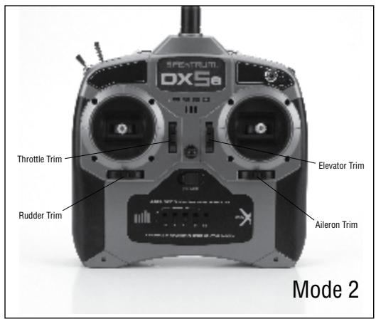
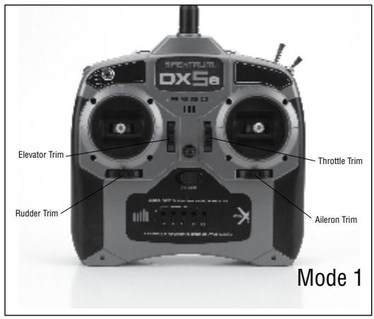
The DX5e features digital trims. Each time a trimmer is moved the servo output will change one step. If the trimmer is held, the output will scroll in that direction until the trimmer is released or the output reaches its end.
LOW BATTERY ALARM
When the battery voltage drops below 4.7 volts, an alarm will sound and the voltage LEDs will flash.
TRAINER
The DX5e offers a trainer function that allows the transmitter to operate as a master or slave. The trainer switch is located on the top of the transmitter, on the left side for Mode 2 and the right side for Mode 1. When using the trainer function, plug the trainer cord (SPM6805) into the trainer port in both the master (controlling) and the slave (training) transmitters. The master transmitter must have the power turned on and the slave transmitter must have the power turned off.
Note: The DX5e trainer system is compatible with all JR and Spektrum transmitters.
MASTER
The DX5e transmitter can be used as a master but the slave transmitter must have the same programming (i.e. reverse switch positions) as the master.
SLAVE
When using the DX5e transmitter as a slave with another DX5e, it's necessary to match all the reverse switch positions.
RECEIVER INSTALLATION
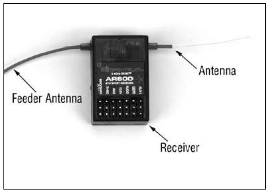
The AR600 incorporates dual receiver antennas, offering the security of dual path RF redundancy. By locating these antennas in slightly different locations in the aircraft, each antenna is exposed to its own RF environment, greatly improving path diversity (the ability for the receiver to see the signal in all conditions).
RECEIVER INSTALLATION
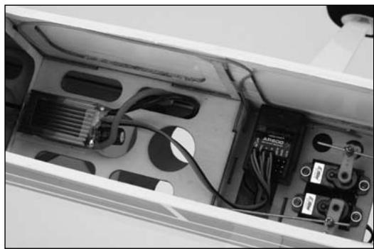
Install the receiver using the same method you would use to install a conventional receiver in your aircraft. Typically, wrap the receiver in protective foam and fasten it in place using rubber bands or hook and loop straps. Alternately, in electric models, it's acceptable to use thick double-sided foam tape to fasten the main receiver in place.
Mount the antennas such that the tip of the feeder (long) antenna is perpendicular (90 degrees) to the short antenna and the antennas are at least 2 inches apart. Essentially, each antenna sees a different RF environment and this is key to maintaining a solid RF link.
BINDING
The AR600 receiver must be bound to the transmitter before it will operate. Binding is the process of teaching the receiver the specific code of the transmitter so it will only connect to that specific transmitter.
Note: RTF aircraft and Radio Systems are pre-bound at the factory. Rebinding is necessary if any settings are changed to ensure proper failsafe settings are achieved.
- To bind an AR600 to a DSM transmitter, insert the BIND/DATA port in the charge plug receptacle.
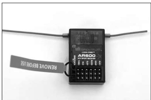
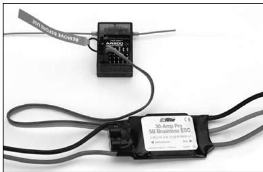
Note: To bind an aircraft with an electronic speed controller that powers the receiver through the throttle channel (ESC/BEC), insert the bind plug into the BIND/DATA port in the receiver and the throttle lead into the throttle port. Proceed to Step #2.
- Power the receiver by plugging in a receiver battery in any port on the receiver. Note that the LED on the receiver should be flashing, indicating that the receiver is in bind mode and ready to be bound to the transmitter.
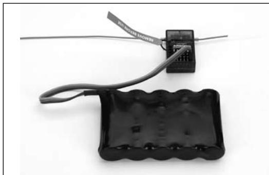
Shown above using a separate receiver pack
Note: When binding using a switch harness and separate receiver pack, a three-wire switch harness must be used such as SPM9530 (not shown). You may need to purchase the Male/Female bind plug SPM6803 in addition to the switch harness.
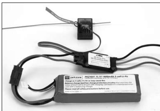
Shown above using an ESC/BEC and a flight pack
- Move the throttle stick and switches on the transmitter to the desired AR600 smartsafe positions, usually low throttle.
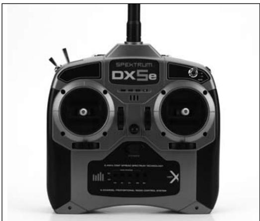
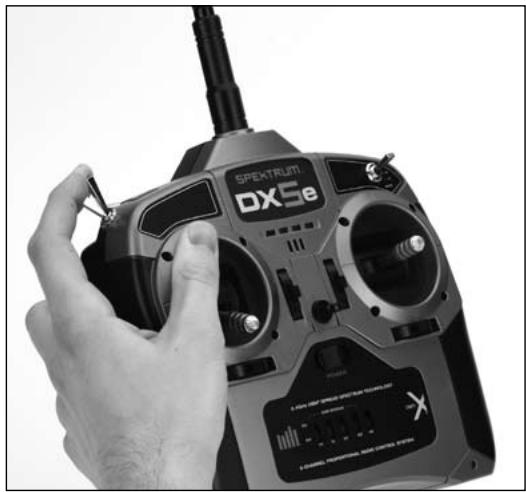
- Pull and hold the trainer switch on the top of the transmitter while turning on the power switch. Release the trainer switch once the LEDs on the front of the transmitter flash, and a series of tones are heard. Within a few seconds the system should connect. Once connected the LED on the receiver will go solid indicating the system is connected.
Note: Continuing to hold the trainer switch during the binding process will prevent the preset smartsafe position from being learned by the receiver.
- Remove the bind plug from the BIND/DATA port on the receiver before you power off the receiver and store it in a convenient place.
- After you've set up your model, it's important to rebind the system so the true low throttle is programmed.
HOW TO RANGE TEST THE DX5E
Before each flying session, and especially with a new model, it is important to perform a range check. The DX5e incorporates a range testing mode which reduces the output power of the transmitter, allowing a range check.
RANGE TESTING THE DX5E
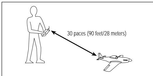
- With the model restrained on the ground, stand 30 paces (approx. 90 feet/28 meters) away from the model.
Note: Prior to performing the range check ensure the correct Smartsafe throttle stick position is established.
- Face the model with the transmitter in your normal flying position. Pull and hold the trainer switch then toggle the HI/LO Rate Switch four times. The LEDs will flash and the alarm will sound indicating the system is in range check mode.
Note: The trainer switch must be held the entire time during the range check process; releasing the trainer switch will exit the range check mode.
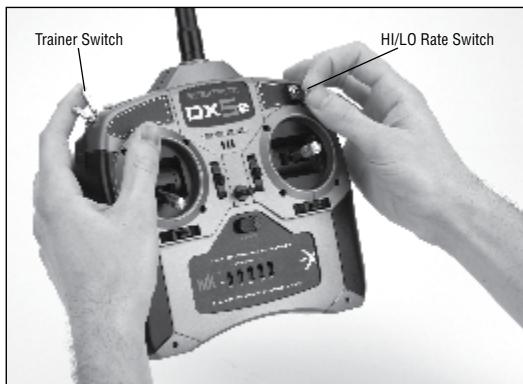
- You should have total control of the model with the trainer switch pulled at 30 paces (90 feet/28 meters).
- If control issues exist, call the Horizon Product Support Team at 1 877 504 0233 or go to horizonhobby.com to find a local Spektrum distributor for service in your country.
AR600 FAILSAFE
- Prevents unintentional electric motor response on start-up.
Establishes low-throttle failsafe if the RF signal is lost. - The AR600 holds all surfaces except throttle in there last commanded position during Failsafe.
- The AR600 throttle Smartsafe position is stored via the throttle stick position on the transmitter.
HOW AR600 FAILSAFE WORKS
RECEIVER POWER ONLY
- When the receiver only is turned on (no transmitter signal is present), the throttle channel has no output—to avoid operating or arming the electronic speed control.
All other channels will have no output signal.
Note: Some analog servos will coast slightly even though there is no signal present. This is normal.
AFTER CONNECTION
- When the transmitter is turned on, and after the receiver connects to the transmitter, normal control of all channels occurs.
- After the system makes a connection, if loss of signal occurs, the AR600 Smartsafe drives the throttle servo only to its preset Smartsafe position (low throttle) that was set during binding.
- All other channels will hold their last commanded position.
SERVO REVERSING
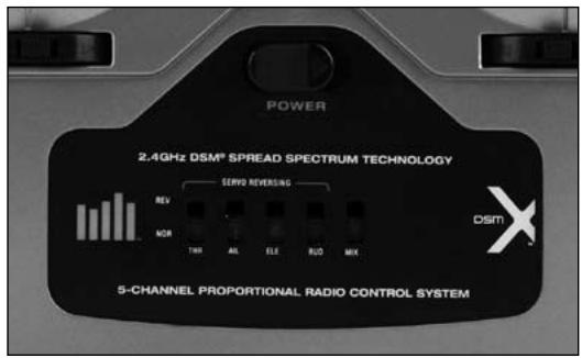
The DX5e features servo reversing on channels 1-4. The switches are located at the lower front of the transmitter and are used to select the direction of each channel. Use a small screwdriver to change the switch position to normal or reverse.
HI/LO RATE
The DX5e offers a high/low rate function on aileron, elevator and rudder. When the HI/LO rate switch is in the "HI" position, 100% travel is achieved on the aileron, elevator and rudder channels. When the switch is in the "LO" position a reduced travel of 70% is achieved on the aileron, elevator and rudder channels. This is useful allowing the aircraft to have a high control rate (switch in the "HI" position) for aggressive maneuvers and a low control rate (switch in "LO" position) for smooth, precise maneuvers.
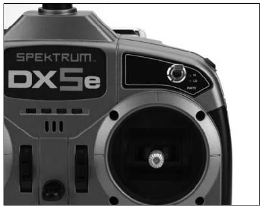
High 100% rate on aileron, elevator and rudder
Low 70% rate on aileron, elevator and rudder
ELEVON/ DELTA MIXING
The DX5e offers an Elevon mix. Elevon (also called delta wing) mixing combines the function of ailerons with the function of the elevator to allow precise control of both roll and pitch for delta wing aircraft. To activate the Elevon mix, move the mix switch to the on (up) position.
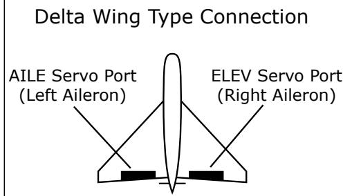
ELEV servo port (right aileron)
- AILE servo port (left aileron)
Note: If proper servo direction cannot be achieved with the servo reversing switches, swap the servo input leads from AILE to ELEV or vice versa.
FRANCE RF SETTING
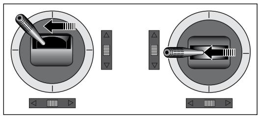
TO SET FRANCE MODE:
Hold the trainer switch and push and hold the Aileron trim button to the left. Turn on the transmitter. A series of descending tones should be heard. Release switches.
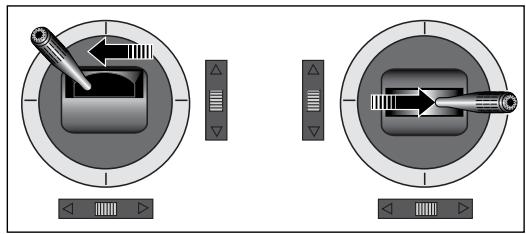
TO SET STANDARD MODE:
Hold the trainer switch and push and hold the Aileron trim button to the right. Turn on the transmitter. A series of ascending tones should be heard. Release switches.
RECEIVER POWER SYSTEM REQUIREMENTS
With all radio installations, it is vital the onboard power system provides adequate power without interruption to the receiver even when the system is fully loaded (servos at maximum flight loads). This becomes especially critical with giant-scale models that utilize multiple high-torque/ high-current servos. Inadequate power systems that are unable to provide the necessary minimum voltage to the receiver during flight loads have become the number-one cause of in-flight failures. Some of the power system components that affect the ability to properly deliver adequate power include: the selected receiver battery pack (number of cells, capacity, cell type, state of charge), switch harness, battery leads, regulator (if used) and, unless it's a regulator, power bus (if used).
While a Spektrum receiver's minimum operational voltage is 3.5 volts, it is highly recommended the system be tested per the guidelines below to a minimum acceptable voltage of 4.8 volts during ground testing. This will provide head room to compensate for battery discharging or if the actual flight loads are greater than the ground test loads.
- When setting up large or complex aircraft with multiple high-torque servos, it's highly recommended that a current and voltmeter (Hangar 9 HAN172) be used. Plug the voltmeter in an open channel port in the receiver and, with the system on, load the control surfaces (apply pressure with your hand) while monitoring the voltage at the receiver. The voltage should remain above 4.8 volts even when all servos are heavily loaded.
-
With the current meter in line with the receiver battery lead, load the control surfaces (apply pressure with your hand) while monitoring the current. The maximum continuous recommended current for a single heavy-duty servo/battery lead is three amps while short-duration current spikes of up to five amps are acceptable. Consequently, if your system draws more than three amps continuous or five amps for short durations, a single battery pack with a single switch harness plugged into the receiver for power will be inadequate. It will be necessary to use multiple packs with multiple switches and multiple leads plugged into the receiver.
-
If using a regulator, it's important the above tests are done for an extended period of 5 minutes. When current passes through a regulator, heat is generated. This heat causes the regulator to increase resistance, which in turn causes even more heat to build up (thermal runaway). While a regulator may provide adequate power for a short duration, it's important to test its ability over time as the regulator may not be able to maintain voltage at significant power levels.
- For really large aircraft or complex models (for example 35% and larger or jets), multiple battery packs with multiple switch harnesses are necessary or in many cases one of the commercially available power boxes/ busses is recommended. No matter what power systems you choose, always carry out test #1 above making sure that the receiver is constantly provided with 4.8 volts or more under all conditions.
- The latest generation of Nickel-Metal Hydride batteries incorporates a new chemistry mandated to be more environmentally friendly. These batteries, when charged with peak detection fast chargers, have a tendency to false peak (not fully charge) repeatedly. These include all brands of NiMH batteries. If using NiMH packs be especially cautious when charging making absolutely sure that the battery is fully charged. It is recommended to use a charger that can display total charge capacity. Note the number of mAh put into a discharged pack to verify it has been charged to full capacity.
TIPS ON USING 2.4GHz SYSTEMS
Your DSM equipped 2.4GHz system is intuitive to operate, functioning nearly identically to FM systems. Following are a few common questions from customers:
- Q: After I've bound the receiver to my transmitter, which do I turn on first when I want to fly?
A: Either one, unless you are using a Smart Bind receiver such as the AR6400 or AR6400L. With a Smart Bind receiver, the transmitter must be turned on approximately 5 seconds before the receiver. - Q: Sometimes the system takes longer to connect or doesn't connect at all. Why?
A: In order for a DSM system to connect, the receiver must receive a large number of uninterrupted signal packets from the transmitter. This process takes just a few seconds, but if the transmitter is too close to the receiver (within 4 feet) or near reflective material (metal objects, carbon fiber materials, tuned pipes, etc.) it may detect its own reflected 2.4GHz energy as "noise". This can delay or prevent connection.
If this happens make sure you are a sufficient distance from metal objects and the receiver itself before you power up and try again. - Q: Is it true that DSM systems are less tolerant of low voltage?
A: All DSM receivers require at least 3.5V to operate normally. Most servos cease to operate below 3.8V. Using multiple high-voltage servos, however, with an inadequate power supply can allow voltage to momentarily drop below 3.5V. This will cause the receiver to "brown out" and reconnect.
All recently manufactured JR and Spektrum DSM receivers feature QuickConnect technology that will reconnect the system within a quarter of a second after battery power recovery should a brownout occur. For more information about Brownout Alert and QuickConnect, please refer to the instruction manual for your receiver. - Q: Sometimes when I power on my DSM system I notice the receiver won't connect and it needs to be rebound to the transmitter. Can this happen in flight?
A: No. A DSM receiver cannot be unbound from its transmitter without specific action by the user. You can accidentally unbind a receiver by inadvertently placing the transmitter into bind mode. If this happens and the transmitter doesn't detect a binding signal from the receiver it can cause the receiver to be unbound. - Q: How important is it that I test my system using a Spektrum Flight Log?
A: All 2.4GHz signals, not just DSM, are affected by proximity to conductive materials such as carbon fiber or metal. Few RTF and ARF sport airplanes or helicopters use enough of these kinds of materials for it to be an issue. If, however, you're flying a sophisticated model that uses a lot of conductive materials in its construction, a Flight Log can be helpful. The information it collects when you fly will help you determine the optimum location for your receiver(s) so you can minimize the effects of these materials on your signal performance. For more details on the Flight Log and how it works, visit SpektrumRC.com.
GENERAL INFORMATION
Servo Precautions
- Do not lubricate servo gears or motors.
- Do not overload retract servos during retracted or extended conditions. Make sure they are able to travel their full deflection. Overloading or stalling a servo can cause excessive current drain.
- Make sure all servos move freely through their rotations and no linkages hang up or bind. A binding control linkage can cause a servo to draw excessive current. A stalled servo can drain a battery pack in a matter of minutes.
- Correct any control surface "buzz" or "flutter" as soon as it is noticed in flight, as this condition can destroy the feedback potentiometer in the servo. It may be extremely dangerous to ignore such "buzz" or "flutter."
- Use the supplied rubber grommets and brass servo eyelets when mounting your servos. Do not overtighten the servo mounting screws, as this negates the dampening effect of the rubber grommets.
- Ensure the servo horn is securely fastened to the servo. Use only the servo arm screws provided; the size is different from other manufacturers.
- Discontinue to use servo arms when they become "yellowed" or discolored. Such servo arms may be brittle and can snap at any time, possibly causing the aircraft to crash.
- Check all related mounting screws and linkages frequently. Aircraft often vibrate, causing linkages and screws to loosen.
General Notes
Radio controlled models are a great source of pleasure. Unfortunately, they can also pose a potential hazard if not operated and maintained properly.
It is imperative to install your radio control system correctly. Additionally, your level of piloting competency must be high enough to ensure that you are able to control your aircraft under all conditions. If you are a newcomer to radio controlled flying, please seek help from an experienced pilot or your local hobby store.
Safety Do's and Don'ts for Pilots
- Ensure that your batteries have been properly charged prior to your initial flight.
- Keep track of the time the system is turned on so you will know how long you can safely operate your system.
- Perform a ground range check prior to the initial flight of the day. See the "Daily Flight Checks Section" for information.
- Check all control surfaces prior to each takeoff.
- Do not fly your model near spectators, parking areas or any other area that could result in injury to people or damage of property.
- Do not fly during adverse weather conditions. Poor visibility can cause disorientation and loss of control of your aircraft. Strong winds can cause similar problems.
- Do not point the transmitter antenna directly toward the model. The radiation pattern from the tip of the antenna is inherently low.
- Do not take chances. If at any time during flight you observe any erratic or abnormal operation, land immediately and do not resume flight until the cause of the problem has been ascertained and corrected. Safety can never be taken lightly.
Federal Aviation Administration
Purpose
This advisory outlines safety standards for operations of model aircraft. We encourage voluntary compliance with these standards.
Background
Attention has been drawn to the increase in model aircraft operation. There is a need for added caution when operating free flight and radio controlled craft in order to avoid creating a noise nuisance or a potential hazard to full-scale aircraft and persons and/or property on the surface.
Operating Standards
Modelers generally are concerned with safety and exercise good judgment when flying model aircraft. However, in the interest of safer skies, we encourage operators of radio controlled and free flight models to comply with the following standards:
a. Exercise vigilance in locating full-scale aircraft (get help if possible) so as not to create a collision hazard.
b. Select an operating site at sufficient distance from populated areas so you do not create a noise problem or a potential hazard.
c. Do not fly higher than 400 feet above the surface.
d. Always operate more than three miles from the boundary of an airport unless you are given permission to be closer by the appropriate air traffic control facility in the case of an airport for which a control zone has been designated or by the airport manager in the case of other airports.
e. Do not hesitate to ask for assistance in complying with these guidelines at the airport traffic control tower or air route traffic control center nearest the site of your proposed operation.
Information Provided By
Director, Air Traffic Service Federal Aviation Administration, Washington, D.C.
Daily Flight Checks
- Check the battery voltage on both the transmitter and the receiver battery packs. Do not fly below 4.7V on the transmitter or below 4.7V on the receiver. To do so can crash your aircraft.
Note: When you check these batteries, ensure that you have the polarities correct on your expanded scale voltmeter. - Check all hardware (linkages, screws, nuts, and bolts) prior to each day's flight. Be sure that binding does not occur and that all parts are properly secured.
- Ensure that all surfaces are moving in the proper manner.
- Perform a ground range check before each day's flying session.
- Prior to starting your aircraft, turn off your transmitter, then turn it back on. Do this each time you start your aircraft. If any critical switches are on without your knowledge, the transmitter alarm will warn you at this time.
- Check that all trim levers are in the proper location.
- All servo pigtails and switch harness plugs should be secured in the receiver. Make sure that the switch harness moves freely in both directions.
WARRANTY INFORMATION
Warranty Period
Exclusive Warranty- Horizon Hobby, Inc., (Horizon) warranties that the Products purchased (the "Product") will be free from defects in materials and workmanship for 1 year from the date of purchase by the Purchaser.
1-Year Limited Warranty
Horizon reserves the right to change or modify this warranty without notice and disclaims all other warranties, express or implied.
(a) This warranty is limited to the original Purchaser ("Purchaser") and is not transferable. REPAIR OR REPLACEMENT AS PROVIDED UNDER THIS WARRANTY IS THE EXCLUSIVE REMEDY OF THE PURCHASER. This warranty covers only those Products purchased from an authorized Horizon dealer. Third party transactions are not covered by this warranty. Proof of purchase is required for all warranty claims.
(b) Limitations- HORIZON MAKES NO WARRANTY OR REPRESENTATION, EXPRESS OR IMPLIED, ABOUT NON-INFRINGEMENT, MERCHANTABILITY OR FITNESS FOR A PARTICULAR PURPOSE OF THE PRODUCT.
THE PURCHASER ACKNOWLEDGES THAT THEY ALONE HAVE DETERMINED THAT THE PRODUCT WILL SUITABLY MEET THE REQUIREMENTS OF THE PURCHASER'S INTENDED USE.
(c) Purchaser Remedy- Horizon's sole obligation hereunder shall be that Horizon will, at its option, (i) repair or (ii) replace, any Product determined by Horizon to be defective. In the event of a defect, these are the Purchaser's exclusive remedies. Horizon reserves the right to inspect any and all equipment involved in a warranty claim. Repair or replacement decisions are at the sole discretion of Horizon. This warranty does not cover cosmetic damage or damage due to acts of God, accident, misuse, abuse, negligence, commercial use, or modification of or to any part of the Product. This warranty does not cover damage due to improper installation, operation, maintenance, or attempted repair by anyone other than Horizon. Return of any Product by Purchaser must be approved in writing by Horizon before shipment.
Damage Limits
HORIZON SHALL NOT BE LIABLE FOR SPECIAL, INDIRECT OR CONSEQUENTIAL DAMAGES, LOSS OF PROFITS OR PRODUCTION OR COMMERCIAL LOSS IN ANY WAY CONNECTED WITH THE PRODUCT, WHETHER SUCH CLAIM IS BASED IN CONTRACT, WARRANTY, NEGLIGENCE, OR STRICT LIABILITY. Further, in no event shall the liability of Horizon exceed the individual price of the Product on which liability is asserted. As Horizon has no control over use, setup, final assembly, modification or misuse, no liability shall be assumed nor accepted for any resulting damage or injury. By the act of use, setup or assembly, the user accepts all resulting liability.
If you as the Purchaser or user are not prepared to accept the liability associated with the use of this Product, you are advised to return this Product immediately in new and unused condition to the place of purchase.
Law: These Terms are governed by Illinois law (without regard to conflict of law principals).
WARRANTY SERVICES
Questions, Assistance, and Repairs
Your local hobby store and/or place of purchase cannot provide warranty support or repair. Once assembly, setup or use of the Product has been started, you must contact Horizon directly. This will enable Horizon to better answer your questions and service you in the event that you may need any assistance. For questions or assistance, please direct your email to productsupport@horizonhobby.com,
or call 877.504.0233 toll free to speak to a Product Support representative. You may also find information on our website at www.horizonhobby.com.
Inspection or Repairs
If this Product needs to be inspected or repaired, please use the Horizon Online Repair Request submission process found on our website or call Horizon to obtain a Return Merchandise Authorization (RMA) number. Pack the Product securely using a shipping carton. Please note that original boxes may be included, but are not designed to withstand the rigors of shipping without additional protection. Ship via a carrier that provides tracking and insurance for lost or damaged parcels, as Horizon is not responsible for merchandise until it arrives and is accepted at our facility. An Online Repair Request is available at www.horizonhobby.com under the Repairs tab. If you do not have internet access, please contact Horizon Product Support to obtain a RMA number along with instructions for submitting your product for repair. When calling Horizon, you will be asked to provide your complete name, street address, email address and phone number where you can be reached during business hours. When sending product into Horizon, please include your RMA number, a list of the included items, and a brief summary of the problem. A copy of your original sales receipt must be included for warranty consideration. Be sure your name, address, and RMA number are clearly written on the outside of the shipping carton.
Notice: Do not ship batteries to Horizon. If you have any issue with a battery, please contact the appropriate Horizon Product Support office.
Warranty Inspection and Repairs
To receive warranty service, you must include your original sales receipt verifying the proof-of-purchase date. Provided warranty conditions have been met, your Product will be repaired or replaced free of charge. Repair or replacement decisions are at the sole discretion of Horizon.
Non-Warranty Repairs
Should your repair not be covered by warranty the repair will be completed and payment will be required without notification or estimate of the expense unless the expense exceeds 50% of the retail purchase cost. By submitting the item for repair you are agreeing to payment of the repair without notification. Repair estimates are available upon request. You must include this request with your repair.
Non-warranty repair estimates will be billed a minimum of 12 hour of labor. In addition you will be billed for return freight. Horizon accepts money orders and cashiers checks, as well as Visa, MasterCard, American Express, and Discover cards. By submitting any item to Horizon for inspection or repair, you are agreeing to Horizon's Terms and Conditions found on our website under the Repairs tab.
| Country of Purchase | Horizon Hobby | Address | Phone Number/ Email |
| United States | Horizon Service Center (Electronics and engines) | 4105 Fieldstone Rd Champaign, Illinois 61822 USA | 877-504-0233 Online Repair Request visit: www.horizonhobby.com/repairs/ |
| Horizon Product Support (All other products) | 4105 Fieldstone Rd Champaign, Illinois 61822 USA | 877-504-0233 productsupport@horizonhobby.com | |
| United Kingdom | Horizon Hobby Limited | Units 1-4 Ployters Rd Staple Tye Harlow, Essex CM18 7NS United Kingdom | +44 (0) 1279 641 097 sales@horizonhobby.co.uk |
| Germany | Horizon Technischer Service | Hamburger Str. 10 25335 Elmshorn Germany | +49 4121 46199 66 service@horizonhobby.de |
| France | Horizon Hobby SAS | 14 Rue Gustave Eiffel Zone d'Activité du Réveil Matin 91230 Montgeron | +33 (0) 1 60 47 44 70 infofrance@horizonhobby.com |
FCC INFORMATION
This device complies with part 15 of the FCC rules. Operation is subject to the following two conditions: (1) This device may not cause harmful interference, and (2) this device must accept any interference received, including interference that may cause undesired operation.
Caution: Changes or modifications not expressly approved by Horizon Hobby, Inc. could void the user's authority to operate the equipment.
This product contains a radio transmitter with wireless technology which has been tested and found to be compliant with the applicable regulations governing a radio transmitter in the 2.400GHz to 2.4835GHz frequency range.
Antenna Separation Distance
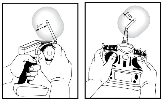
When operating your Spektrum transmitter, please be sure to maintain a separation distance of at least 5 cm between your body (excluding fingers, hands, wrists, ankles and feet) and the antenna to meet RF exposure safety requirements as determined by FCC regulations.
The illustrations below show the approximate 5 cm RF exposure area and typical hand placement when operating your Spektrum transmitter.
Compliance Information for the European Union
SPM5510, SPM55101

| AT | BG | CZ | CY | DE |
| DK | ES | FI | FR | GR |
| HU | IE | IT | LT | LU |
| LV | MT | NL | PL | PT |
| RO | SE | SI | SK | UK |
Declaration of Conformity

(in accordance with ISO/IEC 17050-1)
No. HH20100225U4
Product(s):
Spektrum DX5e Transmitter
Item Number(s):
SPM5510, SPM55101
Equipment class:
2
The objects of declaration described above are in conformity with the requirements of the specifications listed below, following the provisions of the European R&TTE directive 1999/5/EC:
EN 60950
Safety
requirements for Radio
equipment
EN 300-328-V1.7.1
ERM requirements for
wideband transmission
systems operating in the
2.4 GHz ISM band
Signed for and on behalf of:
Horizon Hobby, Inc.
Champaign, IL USA
Feb 25, 2010

Steven A. Hall
Vice President
International Operations and Risk Management
Horizon Hobby, Inc.
INSTRUCTIONS FOR DISPOSAL OF WEEE BY USERS IN THE EUROPEAN UNION
This product must not be disposed of with other waste. Instead, it is the user's responsibility to dispose of their waste equipment by handing it over to a designated collection point for the
recycling of waste electrical and electronic equipment. The separate collection and recycling of your waste equipment at the time of disposal will help to conserve natural resources and ensure that it is recycled in a manner that protects human health and the environment. For more information about where you can drop off your waste equipment for recycling, please contact your local city office, your household waste disposal service or where you purchased the product.
HINWEIS
ELEVON/DELTA MISCHER
Declaration of conformity in accordance with the Radio and Telecommunications Terminal Equipment Act (FETG) and directive 1999/5/EG (R&TTE)
Declaration of conformity in accordance with the Radio and Telecommunications Terminal Equipment Act (FETG) and directive 1999/5/EG (R&TTE)
declares the product:
Geräteklasse: 2
equipment class
Harmonised standards applied:
Health and safety requirements pursuant to §3 (1) 1.(article 3(1)a))
EN 301 489-1 V1.6.1
Protection requirement concerning electromagnetic compatibility
§3 (1) 2, (article 3 (1)b))
§ 3 (2)(Articlek 3 (2))
Measures for the efficient use of the radio frequency spectrum
§ 3 (2) (Article 3 (2))
CE
Elmshorn, 02.25.2010

Steven A. Hall
Vice President International Operations and
Risk Management
Horizon Hobby, Inc.

Birgit Schamuhn
Geschäftsführerin
Managing Director
DOUBLE DÉBATTEMENT (RATE HI/LO)
ERM requirements for wideband transmission systems operating in the 2.4 GHz ISM band
- MEANING OF SPECIAL LANGUAGE:
- TABLE OF CONTENTS
- FRANCE RF SETTING
- DSMX
- HOW DOES DSMX WORK?
- DSMX OPERATIONAL DIFFERENCES
- FOLLOWING ARE THE OPERATIONAL DIFFERENCES:
- FLIGHT LOG RECORDING-FADES HIGHER THAN DSM2
- JUST HOW GOOD IS DSMX?
- IS DSMX COMPATIBLE WITH DSM2?
- CAN DSM2 TRANSMITTERS BE UPGRADED TO DSMX?
- DOES DSMX HAVE MODELMATCH AND SERVOSYNC?
- SPEKTRUM DX5E 5-CHANNEL DSM FULL RANGE SYSTEM
- DSM TECHNOLOGY
- DSMX TECHNOLOGY
- DSMX ON:
- DSM2 ON:
- RECEIVERCOMPATIBILITY
- INSTALLING THE TRANSMITTER BATTERIES
- BATTERY INSTALLATION
- CHARGING BATTERIES
- TRANSMITTER POLARITY
- DIGITAL TRIMS
- LOW BATTERY ALARM
- TRAINER
- MASTER
- SLAVE
- RECEIVER INSTALLATION
- BINDING
- Shown above using a separate receiver pack
- HOW TO RANGE TEST THE DX5E
- RANGE TESTING THE DX5E
- AR600 FAILSAFE
- HOW AR600 FAILSAFE WORKS
- RECEIVER POWER ONLY
- AFTER CONNECTION
- SERVO REVERSING
- HI/LO RATE
- ELEVON/ DELTA MIXING
- TO SET FRANCE MODE:
- TO SET STANDARD MODE:
- RECEIVER POWER SYSTEM REQUIREMENTS
- TIPS ON USING 2.4GHz SYSTEMS
- GENERAL INFORMATION
- Servo Precautions
- General Notes
- Safety Do's and Don'ts for Pilots
- Federal Aviation Administration
- Purpose
- Background
- Operating Standards
- Information Provided By
- Daily Flight Checks
- WARRANTY INFORMATION
- Warranty Period
- 1-Year Limited Warranty
- Damage Limits
- WARRANTY SERVICES
- Questions, Assistance, and Repairs
- Inspection or Repairs
- Warranty Inspection and Repairs
- Non-Warranty Repairs
- FCC INFORMATION
- Antenna Separation Distance
- Compliance Information for the European Union
- Declaration of Conformity
- INSTRUCTIONS FOR DISPOSAL OF WEEE BY USERS IN THE EUROPEAN UNION
- HINWEIS
- ELEVON/DELTA MISCHER
- CE
- DOUBLE DÉBATTEMENT (RATE HI/LO)
Brand : SPEKTRUM
Model : DX5E
Category : Remote control transmitter