
B91UT - Audio Effects ZOOM - Free user manual and instructions
Find the device manual for free B91UT ZOOM in PDF.
| Product Type | Multi-effects processor for bass |
| Brand | ZOOM |
| Model | B9.1ut |
| Sampling | 96 kHz / 24-bit, 32-bit internal processing |
| Frequency Response | Up to 40 kHz |
| Input Noise | -120 dB or better |
| Built-in Effects | 112 effects, up to 10 simultaneous |
| Patches | 160 patches (80 presets + 80 user) |
| Tube Booster | Yes (tube/transistor blend) |
| Expression Pedal | Built-in Z Pedal (vertical and horizontal motion) |
| Connectors | 6.35 mm input jack, L/MONO and R output jacks, balanced XLR outputs, effects loop (Send/Return), AUX input, USB, MIDI IN/OUT, external control |
| Power Supply | Included AC adapter (DC 9V) |
| Power Consumption | Approx. 1.5 W (with adapter) |
| Dimensions (approx.) | Width: 200 mm, Depth: 200 mm, Height: 60 mm (estimated from photos) |
| Weight (approx.) | 1.5 kg (estimate) |
| Tuner | Built-in chromatic and bass tuner (A4 range = 435-445 Hz) |
| USB Audio Interface | Yes (compatible with included Cubase LE 4) |
| MIDI | Input/Output, supports Program Change, Control Change |
| Operating Modes | Manual, Play, Edit, Store, Bypass/Mute |
| Maintenance and Cleaning | Use a soft, dry cloth. Do not use solvents or abrasive products. |
| Safety | Do not open the casing. Use only the supplied adapter. Avoid humidity and extreme temperatures. |
| Spare Parts and Repairability | Do not attempt repairs. Contact an authorized ZOOM service center. |
Frequently Asked Questions - B91UT ZOOM
User questions about B91UT ZOOM
0 question about this device. Answer the ones you know or ask your own.
Ask a new question about this device
Download the instructions for your Audio Effects in PDF format for free! Find your manual B91UT - ZOOM and take your electronic device back in hand. On this page are published all the documents necessary for the use of your device. B91UT by ZOOM.
USER MANUAL B91UT ZOOM
BASS EFFECTS CONSOLE
B9.1ut
Operation Manual
200m
©ZOOM Corporation
Reproduction of this manual, in whole or in part, by any means, is prohibited.
Safety Precautions / Usage Precautions
SAFETY PRECAUTIONS
In this manual, symbols are used to highlight warnings and cautions for you to read so that accidents can be prevented. The meanings of these symbols are as follows:

This symbol indicates explanations about extremely dangerous matters. If users ignore this symbol and handle the device the wrong way, serious injury or death could result.

This symbol indicates explanations about dangerous matters. If users ignore this symbol and handle the device the wrong way, bodily injury and damage to the equipment could result.
Please observe the following safety tips and precautions to ensure hazard-free use of the B9.1ut
Power requirements

- Be sure to use only the AC adapter which is supplied with the B9.lut. The use of any other adapter may lead to malfunction and damage and pose a fire hazard or other safety hazard.
- Connect the AC adapter only to an AC outlet that supplies the rated voltage required by the adapter.
- When disconnecting the AC adapter from the AC outlet, always grasp the plug and do not pull at the cable.
- During lightning or when not using the unit for an extended period, disconnect the AC adapter from the AC outlet.
- Do not pinch the power cord, bend it forcefully, or place heavy objects on the power cord.
Environment

To prevent the risk of fire, electric shock or malfunction, avoid using your B9.lut in environments where it will be exposed to:
- Extreme temperatures
- Heat sources such as radiators or stoves
High humidity or moisture - Excessive dust or sand
- Excessive vibration or shock
Keep a minimum distance of 5cm around the unit for sufficient ventilation.
Do not impede the ventilation openings with objects such as newspapers or curtains.
Handling

- Never place objects filled with liquids, such as vases, on the B9.1ut since this can cause electric shock.
- Do not place naked flame sources, such as lighted
candles, on the B9.1ut since this can cause fire.

- The B9.lut is a precision instrument. Do not exert undue pressure on the keys and other controls. Also take care not to drop the unit, and do not subject it to shock or excessive pressure.
- Take care that no foreign objects (coins or pins etc.) or liquids can enter the unit.
Connecting cables and input and output jacks

You should always turn off the power to the B9.1ut and all other equipment before connecting or disconnecting any cables. Also make sure to disconnect all connection cables and the power cord before moving the B9.1ut.
Alterations

Never open the case of the B9.lut or attempt to modify the product in any way since this can result in damage to the unit.
Volume

Do not use the B9.lut at a loud volume for a long time since this can cause hearing impairment.
Usage Precautions
Electrical interference
For safety considerations, the B9.1ut has been designed to provide maximum protection against the emission of electromagnetic radiation from inside the device, and protection from external interference. However, equipment that is very susceptible to interference or that emits powerful electromagnetic waves should not be placed near the B9.1ut, as the possibility of interference cannot be ruled out entirely.
With any type of digital control device, the B9.1ut included, electromagnetic interference can cause malfunctioning and can corrupt or destroy data. Care should be taken to minimize the risk of damage.
Cleaning
Use a soft, dry cloth to clean the B9.1ut. If necessary, slightly moisten the cloth. Do not use abrasive cleanser, wax, or solvents (such as paint thinner or cleaning alcohol), since these may dull the finish or damage the surface.
Please keep this manual in a convenient place for future reference.
- MIDI is a registered trademark of Association of Musical Electronics Industry(AMEI).
Contents
Safety Precautions / Usage Precautions.... 2
Features 4
Terms Used in This Manual 5
Controls and Functions 6
Getting Connected 8
Power-On 9
Quick Guide 1 (Manual Mode/Play Mode Operation) 10
Quick Guide 2 (Edit Mode/Store Mode Operation) 12
Switching Modules On and Off (Manual Mode) 14
Panel display 14
Selecting patches 14
Turning a module on and off 15
Adjusting the sound 16
Using the Accelerator 17
Selecting Patches for Playing (Play Mode) . 18
Using the Tuner (Bypass/Mute Mode) 20
Using the chromatic tuner 20
Using the bass tuner 21
Changing the Sound of a Patch (Edit Mode) 23
Patch configuration 23
Basiceditmodesteps 23
Changing a patch name 26
Storing Patches and Banks (Store Mode) 27
Storing/swapping patches 27
Storing/swapping banks 28
Returning patches to factory default condition 29
Using the Expression Pedal 30
About the expression pedal 30
Assigning control targets to the expression pedal 31
Adjusting the expression pedal 33
Using an external expression pedal 34
Adjusting the expression pedal torque. .35
Using the Foot Switches. 36
Making settings for function foot switches 36
Assigning modules to foot switches 1-4 .38
Specifying the tempo for a patch 38
Using the Effect Loop 40
MIDI Usage Examples 42
What you can do with MIDI 42
Selecting the MIDI channel 42
Sending and receiving patch switching information via MIDI (program change). 43
Sending and receiving pedal/switch/key operation information via MIDI (control change) 46
Sending pedal synth playing information via MIDI (note on/note off) 49
Sending and receiving B9.1ut patch data via MIDI. 50
Other Functions 52
Using the ARRM function .52
Using the sound-on-sound function 54
Using the pedal synth function 55
Using the B9.1ut as audio interface for a computer 57
Muting the direct output when using a USB connection 58
Changing the default reference pitch of thetuner 59
Use as a direct box 59
Checking the B9.1ut version 60
Editor/librarian software for the B9.1ut 60
Linking Effects 61
Using the Pickup Select function 61
Changing the insert position of the pre-amp section and WAH/EFX1 module . . . 62
Effect Types and Parameters 64
How to read the parameter table 64
COMP (Compressor) module. 65
WAH/EFX1 (Wah/Effects 1) module. 65
EXT LOOP (External Loop) module 68
ZNR (Zoom Noise Reduction) module 68
PRE-AMP (Preamplifier) module 68
EQ (Equalizer) module 70
CABINET module 71
MOD/EFX2 (Modulation/Effects 2) module. 71
DELAY module 76
REVERB module 77
TOTAL module. 79
Troubleshooting. 80
B9.1ut Specifications 81
MIDI implementation chart. 82
B9.1ut patch/bank number + program number assignment table .83
- Windows, Windows XP, and Windows Vista are registered trademarks of Microsoft Corporation.
- Macintosh is a registered trademark of Apple, Inc..
- All other trademarks, product names, and company names mentioned in this document are the property of their respective owners.
- Manufacturer names and product names mentioned in this document are trademarks or registered trademarks of their respective owners. The names are used only to illustrate sonic characteristics and do not indicate any affiliation with ZOOM CORPORATION.
Features
Thank you for selecting the ZOOM B9.1ut (simply called the "B9.1ut" in this manual). The B9.1ut is a sophisticated Multi Effect Processor with the following features.
- Latest technology for top performance
Excellent sound quality is assured by signal processing featuring 96kHz / 24 bit sampling and internal 32-bit processing. Frequency response remains flat to 40kHz , and input converted noise is an amazing 120dB or better.
Ready-to-use patches
Effect module combinations and settings can be stored and recalled as "patches". The B9.1ut offers 80 patches in the read-only preset group, plus 80 patches in the user group which can be freely rewritten, resulting in a total of 160 choices.
Tube powered Accelerator
The analog input stage features an Accelerator that lets you freely mix the signal amplified by a vacuum tube circuit to the solid-stage signal. In this way, you can add characteristic tube compression and distortion to a clean sound.
- Versatile array of effects
Out of a versatile palette of 112 effects, up to ten (including ZNR) can be used simultaneously. Recreate the distortion sound of famous amps and compact effects, apply compressor effects to spruce up the sound, use the 6-band equalizer, control delay, add modulation, or select from many other great effects. Both in quality and versatility, the B9.1ut far surpasses anything in its class. You can even transform the output into a cool synth bass or fretless bass sound.
- Two selectable operation modes (manual mode/play mode)
In manual mode, you can use the foot switches to turn individual effects in patches on and off. This makes it easy to simulate playing with an array of compact effects and stomp boxes. In play mode, the foot switches serve to quickly move between patches.
XLR connectors for direct output
In addition to the OUTPUT jacks, a set of XLR connectors lets you send a balanced line-level signal directly to a PA mixer or recording console. The signal can be branched off either before or after effect processing. A switch for uncoupling the direct signal from ground in case of hum problems is also provided.
Z-Pedal senses not only vertical but even horizontal movement
The B9.1ut comes with a built-in Z-type expression pedal that offers great functionality. The pedal senses not only conventional up/down but also sideways movement. This lets you explore a whole new realm of pedal performance. If you connect an additional expression pedal (FP01/FP02) to the CONTROL IN jack, this can be used as a dedicated volume pedal.
- Programmable function foot switches
Three user-programmable function foot switches further enhance flexibility and let you optimize the unit for a range of applications. Use them to set the delay time, turn hold delay on and off, or for various other tasks.
Please take the time to read this manual carefully, in order to get the most out of your B9.1ut and to ensure optimum performance and reliability.
Terms Used in This Manual
This section explains some important terms that are used throughout the B9.1ut documentation.
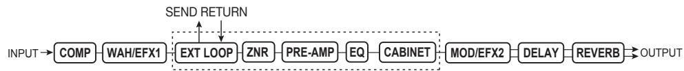
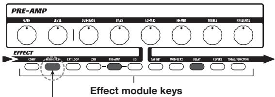
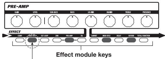
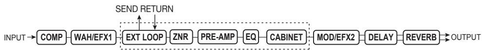
■ Effect module
As shown in the illustration below, the B9.1ut can be thought of as a combination of several single effects. Each of these is referred to as an effect module. The B9.1ut offers a compressor effect module (COMP), amp simulator/synth bass effect module (PRE-AMP), external effect loop control module (EXT LOOP), and more. Parameters such as effect intensity can be adjusted for each module individually, and modules can be switched on and off as desired.
The five modules EXT LOOP, ZNR, PRE-AMP, EQ, and CABINET operate as a virtual preamplifier which is controlled with the knobs and keys on the pre-amp section of the panel.
■ Effect type
Most effect modules comprise several different effects which are referred to as effect types. For example, the modulation effect module (MOD/EFX2) comprises chorus, flanger, pitch shifter, delay, and other effect types. Only one of these can be selected at any time.
■ Effect parameter
All effect modules have aspects that can be controlled. These are called effect parameters, adjusted with the parameter knobs 1 - 4 on the panel. When thinking of an effect module as a compact effect, the parameters change the tone and effect intensity similar to the knobs on the device.
Patch
In the B9.lut, effect module combinations are stored and called up in units referred to as patches. A patch comprises information about the on/off status of each effect module, about the effect type used in each module, and about effect parameter settings. Expression pedal settings and tempo settings are also stored for each patch individually.
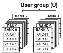
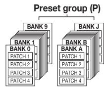
Bank and group
Patches are organized in the user group (U) which can be modified, and in the preset group (P) which is read-only. Since each group comprises 80 patches, there are a total of 160 patches. In the B9.1ut, patches are called up four at a time and selected with the four foot switches. These four patches are together referred to as a bank. There are 20 banks in a group, numbered 0 - 9 and A - J.
■ Modes
The B9.1ut has five different operation modes, as listed below.
- Manual mode
In this mode, you play your instrument while using a specific patch and turning modules in that patch on and off with the foot switches.
This is the default mode of the B9.1ut that is always active when power is turned on.
- Play mode
In this mode, different patches can be selected quickly using the foot switches.
- Edit mode
In this mode, the effect parameters of a patch can be edited (changed).
- Store mode
This mode serves for storing edited patches. It also allows changing the store positions of patches.
- Bypass/mute mode
When the B9.1ut is in the bypass condition, effect processing is temporarily turned off and only the original sound is heard. In the mute mode, all sound is turned off. The tuner can be used in either condition.
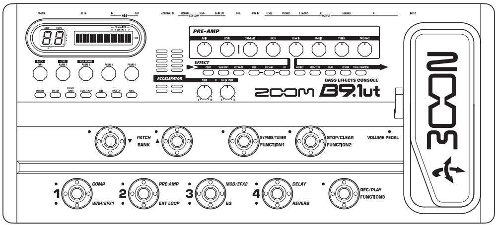
Controls and Functions
B9.1ut Top Panel
Pre-amp section (see next page)
Expression pedal
Control section (see next page)
Accelerator section (see next page)
[VOLUME PEDAL]
LED (see page 33)
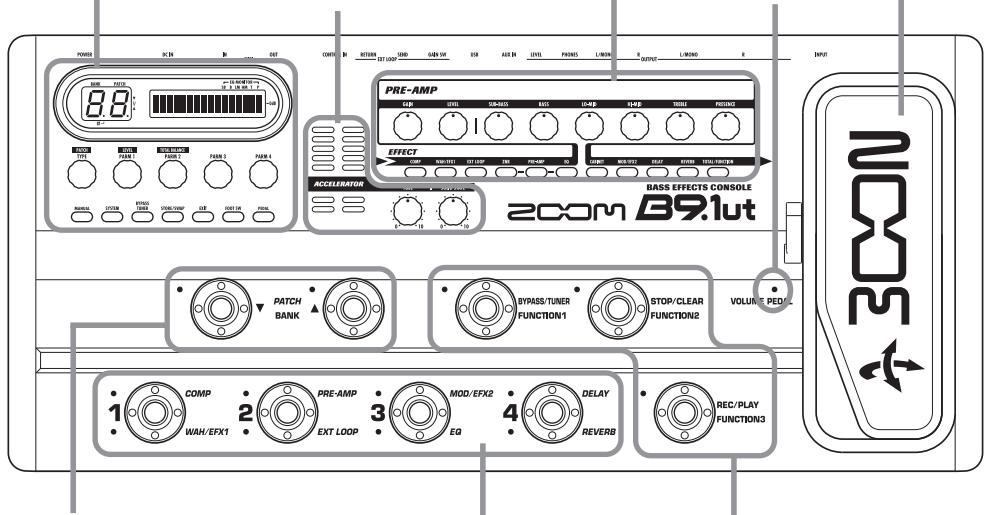
PATCH/BANK [ ] / [ ] foot
Foot switches 1-4
Function foot switches 1-3
switches
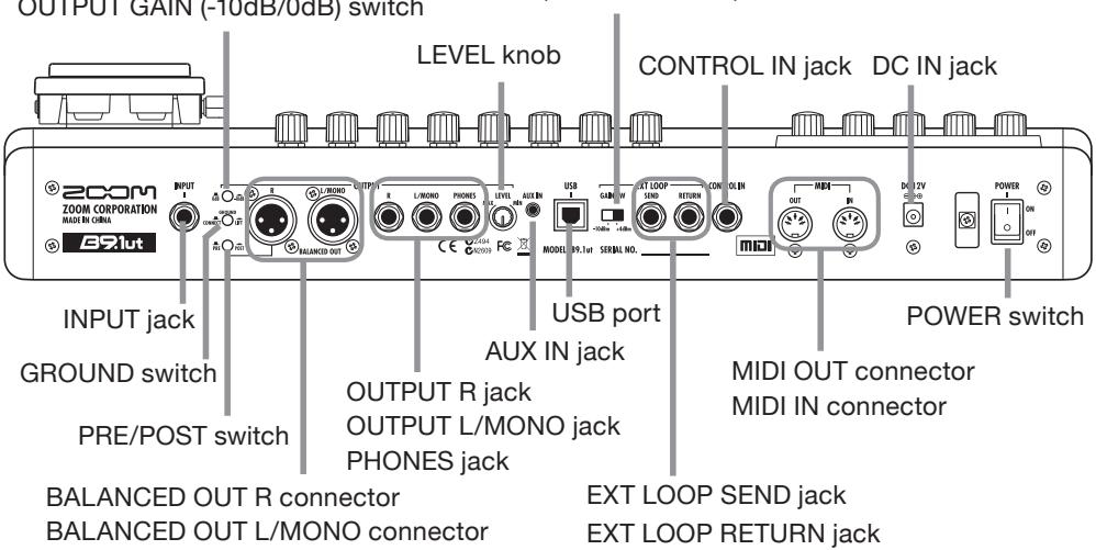
B9.1ut Rear Panel
EXT LOOP GAIN
(-10dBm/+4dBm) switch
Control section
Accelerator section
Pre-amp section
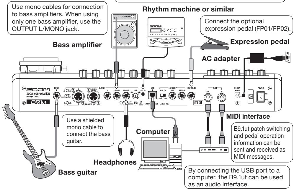
Getting Connected
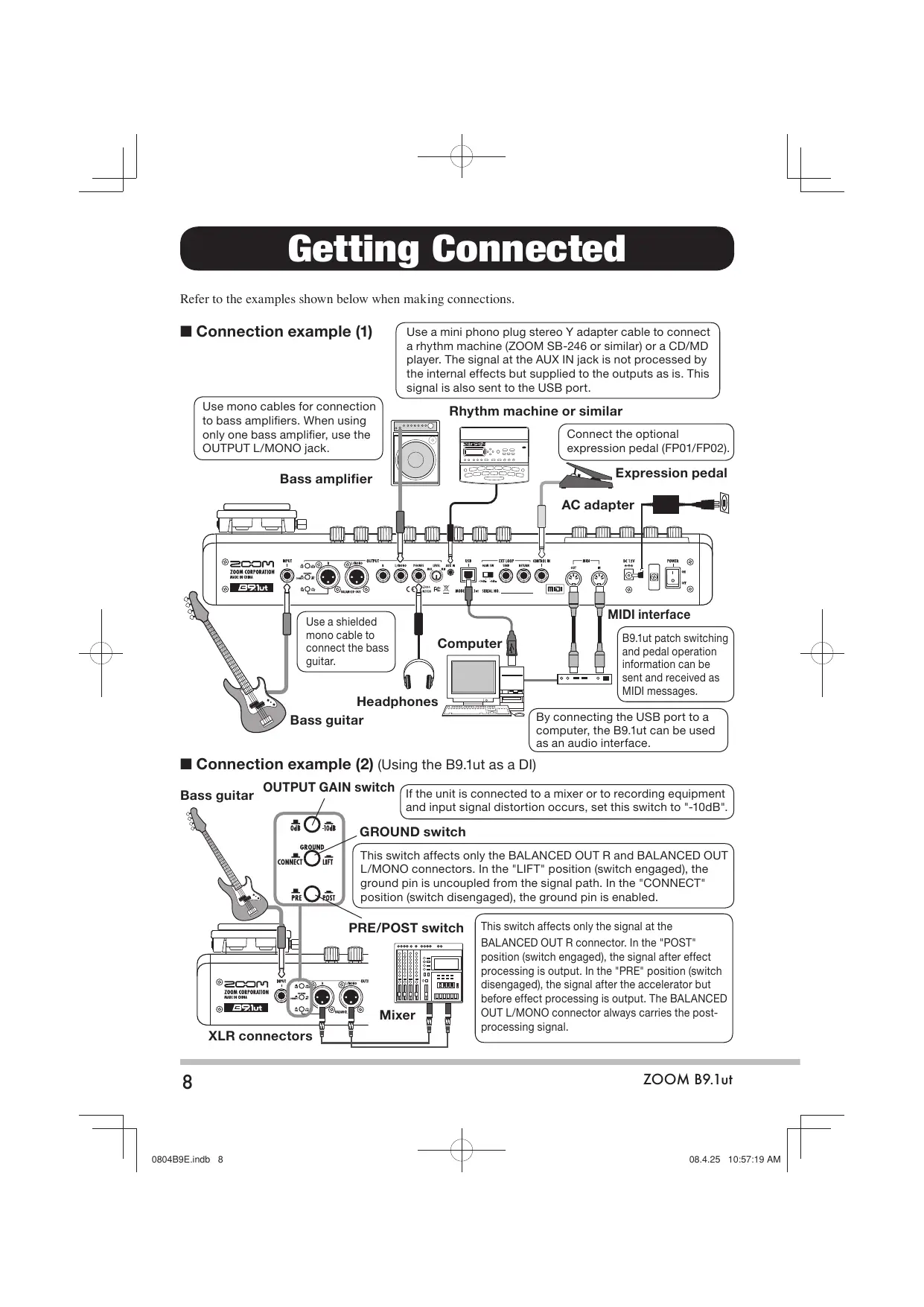
Refer to the examples shown below when making connections.
Connection example (1)
Use a mini phono plug stereo Y adapter cable to connect a rhythm machine (ZOOM SB-246 or similar) or a CD/MD player. The signal at the AUX IN jack is not processed by the internal effects but supplied to the outputs as is. This signal is also sent to the USB port.
■ Connection example (2) (Using the B9.1ut as a DI)
If the unit is connected to a mixer or to recording equipment and input signal distortion occurs, set this switch to "-10dB".
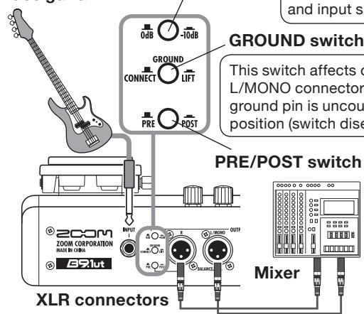
Bass guitar
OUTPUT GAIN switch
GROUND switch
This switch affects only the BALANCED OUT R and BALANCED OUT L/MONO connectors. In the "LIFT" position (switch engaged), the ground pin is uncoupled from the signal path. In the "CONNECT" position (switch disengaged), the ground pin is enabled.
This switch affects only the signal at the BALANCED OUT R connector. In the "POST" position (switch engaged), the signal after effect processing is output. In the "PRE" position (switch disengaged), the signal after the accelerator but before effect processing is output. The BALANCED OUT L/MONO connector always carries the post-processing signal.
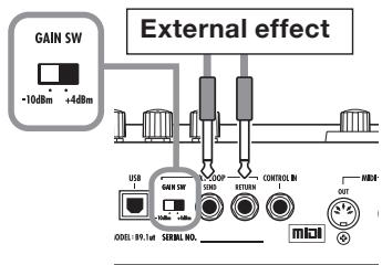
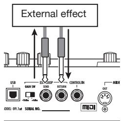
■ Connection example (3) (External effect connection)
When an external effect is connected to the SEND/RETURN jacks, settings such as effect on/off and send/return level can be stored as part of a patch. For details, see page 40.
EXT LOOP GAIN switch
When connecting to an effect that has a rated input level of +4 dBm (rackmount effect or similar), use the "+"dBm" setting. When connecting to an instrument effect or a compact effect, use the "-10 dBm" setting.
Power-On
The steps for turning on the B9.1ut are described below.
- Make sure that any connected bass amplifier is turned off.
In addition, fully turn down the volume control at the bass amplifier. - Plug the AC adapter into an AC outlet and plug the cable from the adapter into the DC IN connector of the B9.1ut.
- Use a monaural cable to connect the bass guitar to the INPUT jack of the B9.1ut. Use a monaural cable to connect the OUTPUT L/MONO (or R) jack to the bass amplifier.
HINT
To monitor with headphones, plug the.
headphone cable into the PHONES jack of the B9.lut.
- Turn power on in the following order: B9.1ut bass amplifier.
NOTE
Proceed with care when powering up the system. If you turn on power to the B9.lut while the bass amplifier is already on, there is a risk of hearing damage and damage to the speakers.
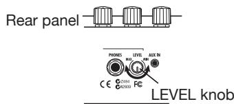
- Play your bass guitar and adjust the volume control on the bass amplifier, on the bass guitar, and the LEVEL knob on the rear panel of the B9.1ut to obtain optimum listening volume.
NOTE
The Accelerator setting also has an influence on the volume ( p, 17) .
HINT
The B9.1ut has a so-called "Pickup Select" feature that lets you match the unit to various kinds of bass guitar pickups. If necessary, select the appropriate setting for your bass guitar the first time you use the B9.1ut ( p.61) .
- To shut down the system, turn power to the respective components off in the reverse order than during power-up.
NOTE
- When the LEVEL knob on the rear panel is turned to maximum, the output level of the B9.Iut is +6 dB.
- For information on Accelerator settings for unity gain (output level is the same as input level), see page 17.
This section explains various basic steps, allowing you to use the B9.1ut right away.
Switching modules on and off with your foot (manual mode)
Immediately after power-on, the unit will be in manual mode, where you can use foot switches 1 - 4 to switch modules on and off.
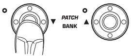
1. Use the PATCH/BANK [] / [] foot switches to select a patch.
Each push on one of the PATCH/BANK [] / [] foot switches changes to the next patch.
[Identical display items in manual mode and play mode]
![ZOOM B91UT - [Identical display items in manual mode and play mode] - 1](/content/2025/01/152193/images/6de36daeaa83c925fe7212a0ccc854ee1ff36ca418bd597e139546c128677d30.jpg)
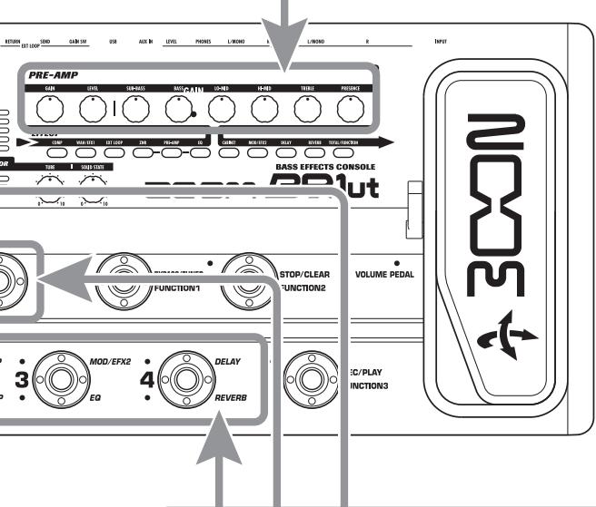
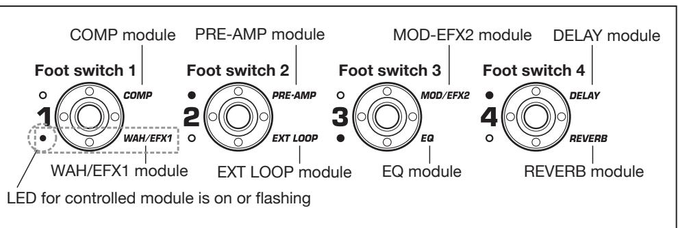
2. Press the foot switch for the module to be switched on and off.
The respective LED for the module assigned to the foot switch changes status. Module on: LED on. Module off: LED flashing.
HINT You can change the modules assigned to the foot switches 1 - 4 ( p.38) .
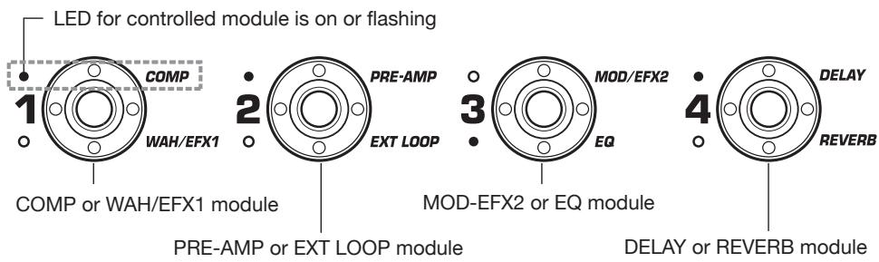
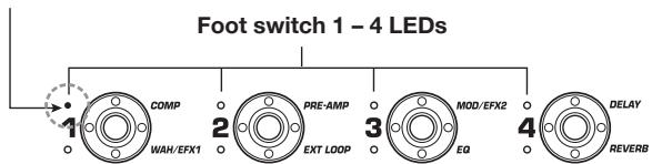
[Modules assigned to foot switches 1 - 4]
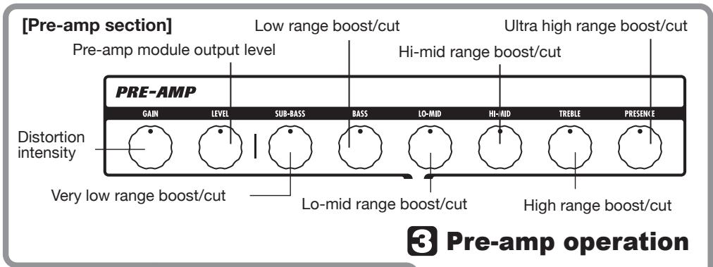
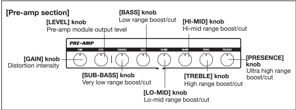
Pre-amp operation
The pre-amp section allows you to adjust distortion intensity and EQ.
- Turn the knobs of the pre-amp section to make adjustments.
The B9.1ut goes into edit mode.
- To return to manual mode or play mode, press the [EXIT] key.
2 Selecting patches (play mode)
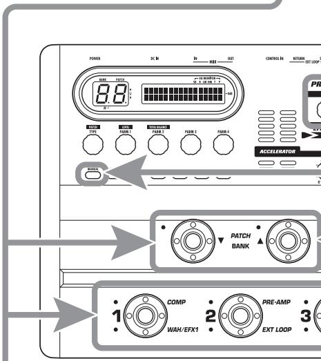
- Press the [MANUAL] key so that the key is off.
The B9.1ut is in play mode. - To select a patch, use the PATCH/BANK [] /[▲] foot switches to select a group/bank, and then use foot switches 1 - 4.
- To return to manual mode, press the [MANUAL] key again so that the key is on.
This section explains how to edit a selected patch and how to store the changes you have made.
1 Editing a patch (edit mode)
1. Press the effect module key for the module to edit.
The unit switches to edit mode. By repeatedly pressing the effect module key, the respective module can be toggled between on and off.
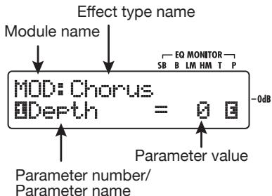
[Display in edit mode]
NOTE
If you press the PRE-AMP/EQ module key, the display will be different. For details, see page 24.
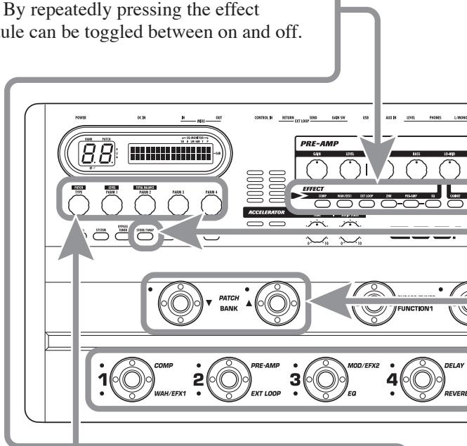
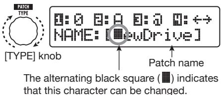
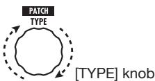
2. Use the [TYPE] knob and parameter knobs 1 - 4 to make adjustments.
![ZOOM B91UT - Use the [TYPE] knob and parameter knobs 1 - 4 to make adjustments. - 1](/content/2025/01/152193/images/8c8cb7f53e4c99af9c80bf0950286e7cf6a4c1d9c93ed5e20adf9856183fa73a.jpg)
[TYPE] knob Changes the effect type.
For information on parameters assigned to the knobs, see page 64-79.
HINT
The major parameters of the PRE-AMP/EQ module can be edited with the knobs of the pre-amp section, in the same way as in manual mode or play mode.
NOTE
The changes that you have made to a patch will be lost when you select another patch. To keep the changes, store the patch first.
Storing a patch (store mode)
1. In play mode, manual mode, or edit mode, press the [STORE/SWAP] key.
![ZOOM B91UT - In play mode, manual mode, or edit mode, press the [STORE/SWAP] key. - 1](/content/2025/01/152193/images/1ee8c3e3eac854d7bd0d9f8f597ff02362fee18b4d5e7497408e604596fc12d9.jpg)
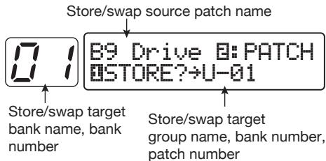
[Display in store mode]
![ZOOM B91UT - In play mode, manual mode, or edit mode, press the [STORE/SWAP] key. - 2](/content/2025/01/152193/images/4352176d2af5ee268dc1b2a7b5a55a22b7164c5675aea6359eac02331aa84351.jpg)
Store target group name, bank number, patch number
2. The indication "PATCH" appears in the top right of the display and the indication "STORE?" in the bottom left.
In this condition, you can store individual patches. If the display is different, use parameter knob 1 to bring up the "STORE?" indication and parameter knob 2 to bring up the "PATCH" indication.
HINT
In store mode, you can swap patches as well as store or swap entire banks ( p.27) .
3. Select the store target bank/patch number.
- When activation sequence was manual mode store mode
- When activation sequence was manual mode edit mode store mode
Use the PATCH/BANK [] / [] foot switches to select the bank and patch.
- When activation sequence was play mode store mode
- When activation sequence was play mode edit mode store mode
Use the PATCH/BANK [] / [] foot switches to select the bank, and then use foot switches 1 - 4 to select the patch.
NOTE • Only user group patches can be specified as store target.
- When a patch from a user group is selected, this patch becomes the default store target.
- When a patch from a preset group is selected, the first user group patch becomes the default store target.
4. Press the [STORE/SWAP] key once more.
The store process is carried out, and the B9.1ut returns to manual mode or play mode.
HINT You can return the user group patches easily to the factory default settings ( p, 29) .
Switching Modules On and Off (Manual Mode)
The condition where foot switches 1 - 4 are used to switch the modules in the currently selected patch on and off individually is called "manual mode". When turning on the B9.1ut, it will start up in this mode.
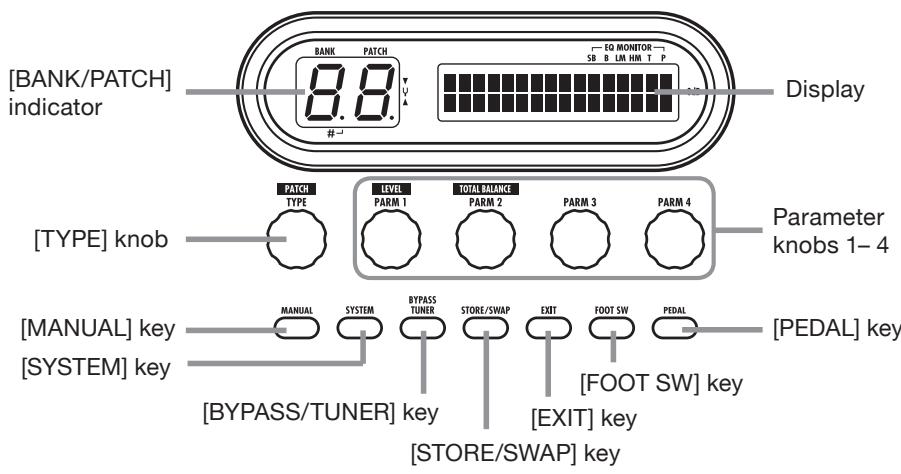
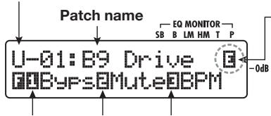
Panel display
In manual mode, the following information is shown on the panel.
Group name/Bank number/Patch number
The group name "P" indicates the preset group, and the group name "U" the user group.
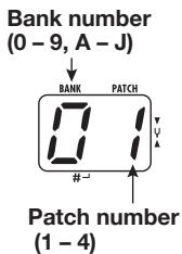
"E" symbol If a setting of the currently selected patch differs from the original setting, the indication "E" (for Edited) appears.
Shows the operation that will be carried out when pressing the respective function foot switch ( p.36).
Keys for modules that are active in the currently selected patch are lit in red.
When the module assigned to the foot switch is on, the LED is lit. When the module is off, the LED flashes.
Foot switch 1-4 LEDs
Selecting patches
This section explains how to select patches in manual mode.
1. Make sure that the [MANUAL] key is lit.
Immediately after power-on, the [MANUAL]
key will be lit and the B9.lut will be in manual mode. If the key is out, press it so that it lights up.
![ZOOM B91UT - Make sure that the [MANUAL] key is lit. - 1](/content/2025/01/152193/images/97188cbd02e1b2f9d37ed00561b55c6958be22bd8d8a89ad193e62ddf203a65b.jpg)
[MANUAL] key (lit)
![ZOOM B91UT - Make sure that the [MANUAL] key is lit. - 2](/content/2025/01/152193/images/3fa88320fe9e1dc963c3f10f5a6fe0f8a16a62242c03bf709f1c546da960b373.jpg)
PATCH/BANK [▲] foot switch
![ZOOM B91UT - Make sure that the [MANUAL] key is lit. - 3](/content/2025/01/152193/images/dd4c94d19a961d9743a14fe9f52ff068b26be120af326b6c2f6cd733b253616c.jpg)
![ZOOM B91UT - Make sure that the [MANUAL] key is lit. - 4](/content/2025/01/152193/images/8449c1b0dd41a04b84f014e0602a33bfc2d3961fd945c7f42d17b7c6387bd429.jpg)
User group (U)
![ZOOM B91UT - Make sure that the [MANUAL] key is lit. - 5](/content/2025/01/152193/images/98225fc91b23e51fea7eea1618d3a7b0c7f842489894de6255b35930085964f0.jpg)
Preset group (P)
![ZOOM B91UT - Make sure that the [MANUAL] key is lit. - 6](/content/2025/01/152193/images/d2878847e66ab95b61969533f9e2ef9a7796180da4e57c393efd00dbc2d88032.jpg)
2. Use the PATCH/BANK [] / [] foot switches to select a patch.
For example, pressing the PATCH/BANK [▲] foot switch repeatedly will cycle through the groups, banks, and patches as shown in the above illustration.
HINT
- The [BANK/PATCH] indicator shows only the bank number and patch number. To identify the current group name, check the display.
- You can also switch the group/bank/patch by turning the [TYPE] knob.
Turning a module on and off
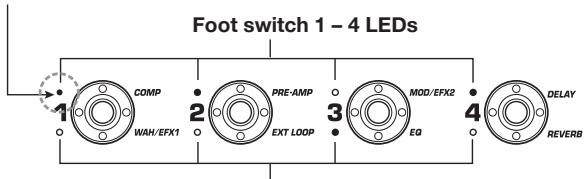
In manual mode, you can use foot switches 1-4 to switch specific modules on and off. The main modules of the currently selected patch can be controlled in this way.
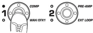
Each foot switch is marked with the names of two modules. One of these modules is controlled by the switch. The top and bottom LEDs of the foot switch indicate which module is being controlled and its current status, as follows. LED lit: module on. LED flashing: module off.
The illustration below shows the foot switches and respective modules.
HINT
- You can change the modules assigned to the foot switches 1 - 4 ( p.38 ).
- The module on/off settings are not automatically retained when you change to another patch. If necessary, store the patch to retain the new settings ( p.27) .
Adjusting the sound
In manual mode, you can use the knobs on the panel to adjust the basic parameters of the preamp section (distortion intensity, EQ boost/cut etc.), as well as the overall volume level (patch level).
- Select the patch in manual mode.
- To change major parameters in the pre-amp section, operate the respective knob (see illustration below).
When you turn a knob, the name and the current setting of the respective parameter appear on the display.
Operating the [SUB-BASS], [BASS], [LO-MID], [HI-MID], [TREBLE], or [PRESENCE] knob will boost or cut the respective band, and the setting is reflected in the graph on the right side of the display.
Name of currently adjusted parameter
HINT
- When you perform this operation, the B9.lut switches to edit mode. To return to manual mode, press the [EXIT] key. (For details on
edit mode, see page 23.)
-
If "Off" is shown on the second line of the display, the pre-amp module or EQ module is set to off. Press the respective module key to turn the module on and then change the parameters.
-
To adjust the overall volume level (patch level), turn parameter knob 1 in manual mode.
The patch level is a parameter that controls the output level of the respective patch. The setting range is 2 - 100. A setting of 80 results in unity gain (no level increase or decrease).
- To adjust the mixing balance between original sound and effect sound (total balance), turn parameter knob 2 after step 3.
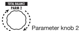
The total balance is a parameter that controls the ratio of effect sound to original sound for each patch. The setting range is 0 - 100. A setting of 0 results in original sound only, and a setting of 100 results in effect sound only.
HINT
- The patch level and total balance are parameters of the TOTAL/FUNCTION module ( p.79) . When you change one of these parameters, the B9.1ut switches to edit mode. To return to manual mode, press the [EXIT] key.
- The changed patch settings are not automatically retained when you change to another patch. If necessary, store the patch to retain the new settings ( p.27) .
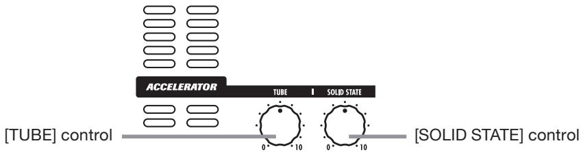
Using the Accelerator
The input stage of the B9.1ut incorporates an Accelerator function that amplifies the analog signal before effect processing using a tube or solid state circuit. This lets you mix characteristic tube compression and distortion with clean solid state sound and then send the signal to the effect circuitry.
HINT
The Accelerator is active in all modes. Accelerator settings are not stored as part of the patch.
To adjust the Accelerator, use the controls of the Accelerator section on the panel. The control functions are explained below.
[TUBE] control
This control adjusts the input signal gain of the tube circuit. Turning the control clockwise increases the volume level and the typical tube sound character.
[SOLID STATE] control
This control adjusts the input signal gain of the solid state circuit. Turning the control clockwise increases only the volume. At the maximum position, gain is about +6 dB. This can be used to increase the gain for the signal before effect processing.
Depending on the settings made for the Accelerator, the effect intensity of the COMP
module and the distortion depth of the PRE-AMP module also will change.
The following setting examples show how to achieve unity gain (same input and output level) for using the tube or solid state controls only. We recommend using these settings as a starting point for making adjustments to the Accelerator.
- Tube control unity gain setting
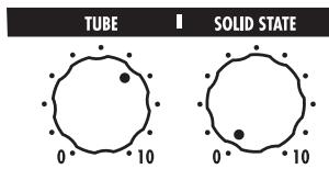
Solid state unity gain setting
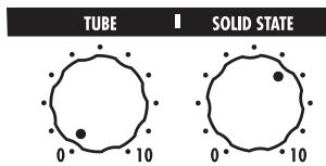
NOTE
When both controls are set to minimum, no signal will be input to the B9.lut.
Selecting Patches for Playing (Play Mode)
This section describes how to use the play mode where you can quickly change patches by using foot switches 1 - 4.
1. Make sure that the [MANUAL] key is out.
![ZOOM B91UT - Make sure that the [MANUAL] key is out. - 1](/content/2025/01/152193/images/34af2703e01b1a24affe3e7165ca0bb2229baf6d4b5ff46a2aae595a5252acd1.jpg)
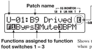
When the [MANUAL] key is out, the B9.1ut is in play mode. In play mode, the following information is shown on the panel.
![ZOOM B91UT - Make sure that the [MANUAL] key is out. - 2](/content/2025/01/152193/images/d40b08df836853f06fb83a861fb4f849dfba6a553b2e49f4fcb490cef20c4a60.jpg)
Group name/Bank number/Patch number
The group name "P" indicates the preset group, and the group name "U" the user group.
"E" symbol
If a setting of the currently selected patch differs from the original setting, the indication "E" (for Edited) appears.
Shows the operation that will be carried out when pressing the respective function foot switch ( p.36)
Functions assigned to function foot switches 1-3
Keys for modules that are active in the currently selected patch are lit in red.
The LED of the foot switch for the currently selected patch is lit.
2. Press a foot switch 1 - 4 which corresponds to the patch you want.
The LED of the pressed switch lights up, indicating that a new patch has been called up.
4. To return to manual mode, press the [MANUAL] key.
![ZOOM B91UT - To return to manual mode, press the [MANUAL] key. - 1](/content/2025/01/152193/images/cff062d7e7ce67be393267adfc2248778cd1b34b7761a29aadebdf74acafefd5.jpg)
HINT
When you press a foot switch whose LED is lit, the same patch is called up once more.
3. To switch to a patch in another bank, use the PATCH/BANK [▼]/[▲] foot switches to change the bank and then use foot switches 1 - 4 to select the patch.
![ZOOM B91UT - To switch to a patch in another bank, use the PATCH/BANK [▼]/[▲] foot switches to change the bank and then use foot switches 1 - 4 to select the patch. - 1](/content/2025/01/152193/images/91f647657d1f9abfca83acf91678bf117a072b47998e29fa39a1d5c613b45847.jpg)
HINT
- You can also switch the group/bank/patch by turning the [TYPE] knob.
- In play mode, as in manual mode, you can use the knobs on the panel to control major parameters of the pre-amp section (distortion intensity, EQ boost/cut, etc.) and the Accelerator. For information on how to do this, see "Adjusting the sound" on page 16.
From play mode, you can switch to edit mode for editing patches. For details on edit mode, see page 23.
Using the Tuner (Bypass/Mute Mode)
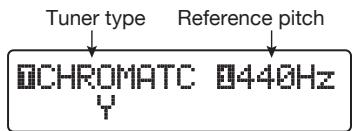
The B9.1ut incorporates a chromatic tuner and a standard type bass tuner.
This section describes how to use the tuner functions.
Using the chromatictuner
To use the chromatic tuner function, proceed as follows.
1. In manual mode, play mode, or edit mode, press and hold the [BYPASS/TUNER] key.
![ZOOM B91UT - In manual mode, play mode, or edit mode, press and hold the [BYPASS/TUNER] key. - 1](/content/2025/01/152193/images/c9963a014c0061a47476a2e2982c616e4311713d9b677b3efccc02434be3c060.jpg)
To use the tuner, the B9.1ut must be set to the bypass mode (effect sound off) or mute mode (original sound and effect sound both off).
- To switch to the bypass mode
Briefly press and release the [BYPASS/TUNER] key so that the key lights up. The B9.1ut is now in the bypass mode.

BYPASS
HINT
In the default condition, each patch of the B9.lut has the bypass on/off switching function assigned to function foot switch 1.
- To switch to the mute mode
Hold the [BYPASS/TUNER] key until the indication "BYPASS" changes to "MUTE". Then release the key. The B9.1ut is now in the mute mode.

MUTE
Release key when "MUTE" is shown
After "BYPASS" or "MUTE" is shown, the B9.1ut automatically switches to the tuning display.
HINT
- In bypass mode, the built-in expression pedal functions as a volume pedal. (In the mute mode, the pedal has no effect.)
- By turning the [TYPE] knob, you can switch between the chromatic tuner and the bass tuner. For information on the bass tuner, see the next section.
- The reverse "T" or number indication on the display indicates that the [TYPE] knob or the corresponding parameter knob can be used for adjustment.
2. Play the open string to tune.
The left digit of the [BANK/PATCH] indicator shows the note which is closest to the current pitch.
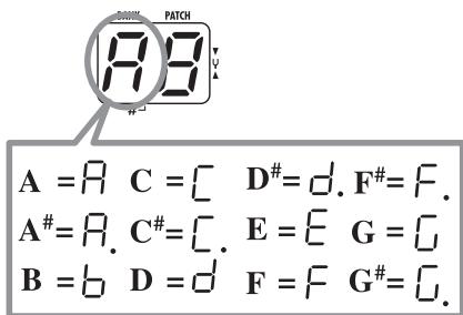
The right digit of the [BANK/PATCH] indicator shows how the pitch differs from the displayed note.
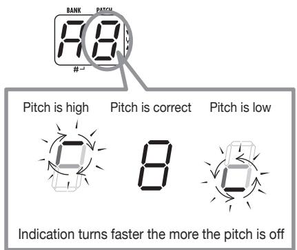
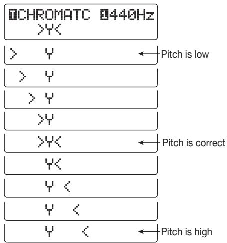
The > < under the display also shows by how much the pitch differs.
3. Tune the string of your instrument while checking the note and pitch indication.
HINT
First you should perform rough tuning to bring up the desired note indication. Then fine tune the pitch while watching the right digit of the [BANK/PATCH] indicator and the lower part of the display.
4. To change the reference pitch of the tuner, turn parameter knob 1.

CHROMATC 442Hz
Parameter knob 1
After the B9.1ut is turned on, the tuner reference pitch is always "440 Hz (center A = 440 Hz). The adjustment range using parameter knob 1 is center A = 435 - 445 Hz, in 1-Hz steps.
HINT
When the B9.lut is turned off and on again, the reference pitch will be reset to 440Hz . You can change the default frequency that will be used after a reset ( p.59)
5. When tuning is completed, press the [BYPASS/TUNER] key.
The B9.1ut returns to manual mode or play mode.
Using the bass tuner
Besides chromatic tuning, the B9.1ut also offers standard tuning for bass. To use this function, proceed as follows.
1. Switch the B9.1ut to the bypass or mute mode as described in step 1 of "Using the chromatic tuner".
The display shows the tuning indication.
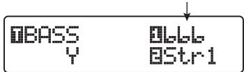
2. Turn the [TYPE] knob to select "BASS" as tuner type.
The [BANK/PATCH] indicator display changes as follows.
![ZOOM B91UT - Turn the [TYPE] knob to select "BASS" as tuner type. - 1](/content/2025/01/152193/images/a08b7150e5673dbd1049add9df4bcf62e1ed108849a211b6184117221234eedd.jpg)
The note names for each string are shown in the table below.
| String number | Note name |
| Str1 | L |
| Str2 | d |
| Str3 | R |
| Str4 | E |
| Str5 | b |
3. If necessary, turn parameter knob 1 to change the reference pitch of the tuner.
The setting range is center A = 435 - 445Hz , in 1-Hz steps.
If "BASS" has been selected as tuning type, turning parameter knob 1 further counterclockwise from the "435" setting selects the setting "b" (one semitone lower), "bb" (two semitones lower), and "bbb" (three semitones lower).
Optional tuning to 1 - 3 semitones lower
HINT
When the B9.lut is turned off and on again, the reference pitch will be reset to 440Hz . You can change the default frequency that will be used after a reset ( p.59)
4. Play the open string of the indicated number and adjust the pitch.
- Turn parameter knob 2 to change the string number.
- Tune other strings in the same way.
- When tuning is completed, press the [BYPASS/TUNER] key.

The B9.1ut returns to manual mode or play mode.
Changing the Sound of a Patch (Edit Mode)
This section describes how to use the edit mode in which you can change the effect types and settings for each effect module.
Patch configuration
As shown in the "Patch configuration" illustration below, the B9.1ut can be thought of as a series of several single effects (effect modules). A combination of these modules and the settings for each module are stored as a patch.
Almost all modules comprise several different effects (called effect types), one of which is selected at any given time. For example, the MOD/EFX2 module allows selection of either Chorus, PitchShift, Delay, etc.
The elements that determine the sound of a patch are called effect parameters. Each effect type has its own parameters that can be controlled with knobs on the panel. Even within the same module, when the effect type is different, the effect parameters that can be controlled will also be different.
In the module configuration shown below, the series of modules EXT LOOP, ZNR, PRE-AMP, EQ, and CABINET operates as a virtual pre-amp section.
Depending on the application, this section can be inserted after the WAH/EFX1 module or after the DELAY module ( p. 62).
Basic edit mode steps
The basic steps that are normally taken in edit mode are described here. For details on effect types and parameters for each module, see the section "Effect Types and Parameters" on pages 64 - 79.
1. Select the patch to edit.
The patch can be from a preset group (P) or user group (U). However, if you have edited a patch from a preset group, it can only be stored in a user group ( p. 27).
2. In play mode or manual mode, press the effect module key (see illustration on next page) to select the module on which to operate.
The B9.1ut switches to edit mode, and the display changes as follows, according to the selected module.
HINT
The effect module keys for modules that are ON in the currently selected patch are lit in red (keys for modules that are OFF are not lit). When you
[Patch configuration]
Effect module keys
EFFECT

[COMP] key
[EXT LOOP] key
[PRE-AMP] key
[CABINET] key
[DELAY] key
[TOTAL/FUNCTION] key
press a key to select a module, the key color changes to orange (or to green if the module is off).
[PRE-AMP module]
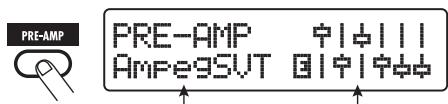
Effect type name
Simplified graphical representation of EQ settings
[EQ module]
Parameter value
NOTE
- If edit mode was activated from manual mode, foot switches 1 - 4 can be used to turn specific modules on and off. The PATCH/BANK [] / [] foot switches can be used to switch patches.
- If edit mode was activated from play mode, the PATCH/BANK [ ] / [▲] foot switches and foot switches 1 - 4 can be used to switch patches. However, note that editing changes will be lost when switching patches during editing, unless you store the patch first.
3. To switch the selected module between on and off, press the same module key once more.
When the module is off, the indication "Module Off" is shown on the display. Pressing the same
key once more in this condition switches the module on.
HINT
- If any module on/off status, effect type selection, or a parameter setting value has been changed at least once, the [STORE/ SWAP] key lights up and the indication "E" appears to the right of the item.
- The "E" indication disappears when the item is returned to the original value. However, if any other item has been changed, the [STORE/ SWAP] key remains lit.
4. To edit the selected module, proceed as follows.
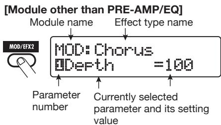
[When a module other than PRE-AMP/EQ is selected]
Switch the effect type as needed with the [TYPE] knob (for modules having several effect types), and use the parameter knobs 1 - 4 to adjust the effect type parameters.
![ZOOM B91UT - [When a module other than PRE-AMP/EQ is selected] - 1](/content/2025/01/152193/images/b6448231b79f8808b34cbc1b41b177120bde6370e123fe10e7e72a86d0347b0c.jpg)
When you turn a parameter knob, the display changes as follows.
![ZOOM B91UT - [When a module other than PRE-AMP/EQ is selected] - 2](/content/2025/01/152193/images/50e6f72f8be49fce6598c927965702c9d3eafd960017a494d016915110bc8165.jpg)
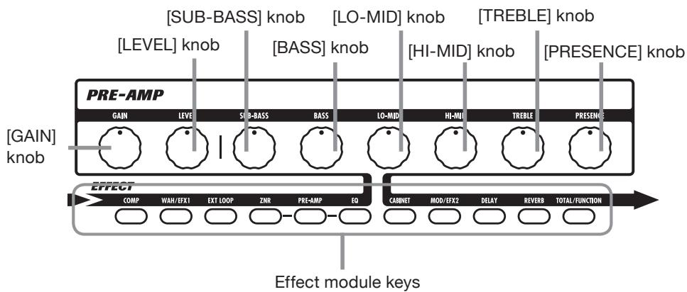
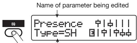
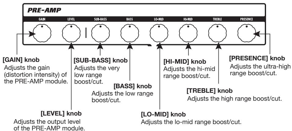
[When PRE-AMP module is selected]
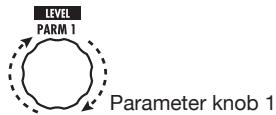
Select the effect type with the [TYPE] knob as required, and use parameter knobs 1 - 4 to adjust the parameters of the effect type. For the PRE-AMP module, parameters are also assigned to the [GAIN] and [LEVEL] knobs in addition to the parameter knobs 1 - 4. The knob assignments for the PRE-AMP module are shown in the illustration below.
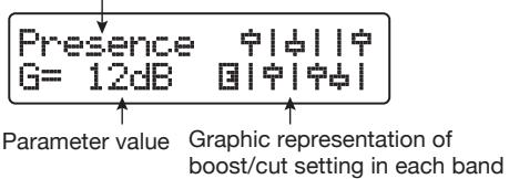
[When EQ module is selected]
Select the frequency band with the [TYPE] knob as required, and use parameter knobs 1 - 3 to adjust the parameters for the respective band. The boost/cut setting for the frequency bands of the EQ module can also be adjusted with the knobs of the pre-amp section. The knob assignments are shown in the illustration below.
HINT
- For information on effect types and parameter assignments, see pages 64 - 79.
- When you adjust PRE-AMP parameters with the knobs of the pre-amp section, the PRE-AMP module is automatically selected. When you adjust EQ parameters, the EQ module is automatically selected.
NOTE
If HPF (high-pass filter) is selected for the Sub-Bass band of the EQ module, or if LPF (low-pass filter) is selected for the Presence band, the boost/cut setting for that band cannot be adjusted. (The indication will be fixed to -12 dB).
5. Repeat steps 2 - 4 to edit other modules in the same way.
6. When editing is finished, press the [EXIT] key.
The B9.1ut returns to the previous mode.
NOTE
- The changes that you have made to a patch will be lost when you select another patch. To keep the changes, store the patch first ( p) 27).
- The patch level (output level of individual patch) and total balance (ratio between original sound and effect sound for individual patch) can be set in the TOTAL/FUNCTION module ( p, 79) .
[Editing PRE-AMP/EQ module with pre-amp section]

Changing a patch name
You can change the name of an edited patch. To do this, proceed as follows.
- In play mode, manual mode, or edit mode, press the [TOTAL/FUNCTION] effect module key.
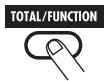
- Turn the [TYPE] knob to bring up the patch name on the lower part of the display.
- Turn parameter knob 4 to move the character input position, and use parameter knobs 1 - 3 to select the new character.
Parameter knobs 1 - 3 select characters as follows.
Parameter knob 1 (numerals): 0 - 9
Parameter knob 2 (letters): A-Z, a-z
Parameter knob 3 (symbols): (space)! " # $ %
$$ \& ^ {\prime} (\quad) * +, -, /;; < > = ? @ [ ] ^ {\wedge} _ {^ {\prime}} {} | $$
- Repeat step 3 until the patch name is as desired. Then press the [EXIT] key.
NOTE
The changes that you have made to a patch name will be lost when you select another patch. To keep the changes, store the patch first ( p) 27).
Storing Patches and Banks (Store Mode)
This section explains how to use the store mode. In store mode, you can store edited patches in memory, or swap the store location of user group patches. Storing and swapping can also be carried out for entire banks. The patches of the user group can be returned to the factory default condition at any time.
Storing/swapping patches
This section explains how to store and swap patches.
- In manual mode, play mode, or edit mode, press the [STORE/SWAP] key.

The B9.1ut switches to the store standby condition, and the currently selected patch becomes the store/swap source.
The [BANK/PATCH] indicator shows the store/ swap target group name and bank number.
HINT
- In the factory default condition, the user group (U) contains the same patches as the preset group (P) .
- If a patch has been edited, it will be stored or swapped in the edited condition.
-
If a patch from the preset group is selected when you press the [STORE/SWAP] key, the corresponding user group patch is automatically selected as store target.
-
To store/swap individual patches, turn parameter knob 2 to bring up the indication "PATCH" in the top right of the display.

B9 Drive B: FATCH
0STORE?→U-01
Parameter knob 2
HINT
When "BANK" is shown, the subsequent operation will be carried out for the entire bank. Make sure that the correct indication is shown.
- Turn parameter knob 1 to bring up the indication "STORE?" or "SWAP?" on the display.

B9 Drive 0: PATCH
STORE?U-01
Parameter knob 1
When "STORE?" is selected, the current patch can be stored as any user patch.
When "SWAP?" is selected, the current user patch can be swapped with any other user patch.
NOTE
If the source patch is from the preset group, the indication "SWAP?" does not appear.
-
Select the store/swap target bank/ patch number.
-
When activation sequence was manual mode store mode
- When activation sequence was manual mode edit mode store mode
Use the PATCH/BANK [ ] / [ ] foot switches to select the bank and patch.
PATCH/BANK [▼]/[▲] foot switches
- When activation sequence was play modee store mode
- When activation sequence was play mode edit mode store mode
Use the PATCH/BANK [ ] / [ ] foot switches to select the bank, and then use foot switches 1-4 to select the patch.
Foot switches 1-4
HINT
You can also select the bank number/patch number with the [TYPE] knob.
5. Press the [STORE/SWAP] key once more.
The store/swap process is carried out, and the B9.1ut then returns to the manual mode or play mode with the store/swap target patch being selected.
By pressing the [EXIT] key instead of the [STORE/SWAP] key, you can cancel the process and return to the previous mode.
NOTE
The Accelerator settings are not stored as part of the patch.
Storing/swapping banks
This section explains how to store and swap entire banks.
- In manual mode, play mode, or edit mode, press the [STORE/SWAP] key.
The B9.1ut switches to the store standby condition, and the currently selected bank becomes the store/swap source.
- To store/swap entire banks, turn parameter knob 2 to bring up the indication "BANK" in the top right of the display.
Store/swapsourceregroupname/banknumber

3. Turn parameter knob 1 to bring up the indication "STORE?" or "SWAP?" on the display.
When "STORE?" is selected, the current bank can be stored as any user bank.
When "SWAP?" is selected, the current user bank can be swapped with any other user bank.
NOTE
If the source bank is from the preset group, the indication "SWAP?" does not appear.
- Use the PATCH/BANK[▼]/[▲] foot switches to select the store/swap target bank.
- Press the [STORE/SWAP] key once more.
The store/swap process is carried out, and the B9.1ut then returns to play mode or manual
mode with the store/swap target bank being selected.
By pressing the [EXIT] key instead of the [STORE/SWAP] key, you can cancel the process and return to the previous mode.

Returning patches to factory default condition
Even if you have made changes to the user group patches, you can return all patches to the factory default condition at any time. To do this, proceed as follows.
NOTE
When you perform the All Initialize function, all patches stored in the user area will be overwritten. Proceed with care.
1. Turn power to the B9.1ut on while holding down the [STORE/SWAP] key.
The indication "All Initialize?" appears on the display.
![ZOOM B91UT - Turn power to the B9.1ut on while holding down the [STORE/SWAP] key. - 1](/content/2025/01/152193/images/0ed3d5fd879293b5e63fc7b7b536f0572f1572d4492e6373d3c631eb33a53f94.jpg)
STORE/SWAP
![ZOOM B91UT - Turn power to the B9.1ut on while holding down the [STORE/SWAP] key. - 2](/content/2025/01/152193/images/582ebe9e5f0787d097b872134455e593e9ce8470b148b35ce21ab8c746a5ee87.jpg)
![ZOOM B91UT - Turn power to the B9.1ut on while holding down the [STORE/SWAP] key. - 3](/content/2025/01/152193/images/06a99b7952bdb062d729865d8cb8ac5075361d4b83ee219544ede6ab74575f8d.jpg)
POWER
All Initialize?
Y:STORE N:EXIT
2. Press the [STORE/SWAP] key once more.
All patches are returned to the factory default condition. The B9.lut then switches to manual mode. By pressing the [EXIT] key before performing step 2, you can cancel the process.
Using the Expression Pedal
This section explains how to use the built-in expression pedal of the B9.1ut or an external expression pedal.
About the expression pedal
The B9.1ut comes standard with one built-in expression pedal that can be used to control specific effect parameters in real time.
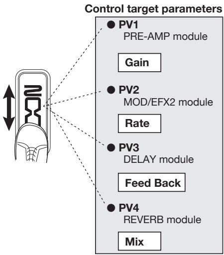
In the vertical direction, this expression pedal has up to four control targets (PV1 to PV4).
For example, when assignments are made as shown in the illustration, four different parameters can be adjusted simultaneously when the pedal is moved up or down.
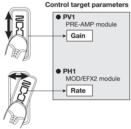
The expression pedal of the B9.lut is a so-called Z-Pedal that senses not only vertical but also horizontal movement. Four additional control targets (PH1 to PH4) can be assigned in the sideways direction. Therefore a total of up to eight parameters (4 vertical and 4 horizontal) can be changed simultaneously.
With a setting such as shown in the following illustration, the pedal adjusts the Gain parameter of the PRE-AMP module when moved in the vertical direction and the Rate parameter of the MOD/EFX2 module when moved in the horizontal direction.
HINT
- The parameter adjustment range can be set for each control target separately.
- In bypass mode, the expression pedal functions as a volume pedal when moved in the vertical direction. (Moving the pedal in the horizontal direction has no effect.)
- In mute mode, the expression pedal has no effect.
NOTE
The expression pedal of the B9.lut is designed for operation with one foot. When the pedal is fully turned to the right, pushing it strongly down, hitting it, or otherwise exerting strong force on it will damage the pedal. Be sure to operate the pedal only within its designated range.
Assigning control targets to the expression pedal
This section explains how to assign a control target to the expression pedal. Four control targets each can be assigned for the vertical direction and the horizontal direction. Module on/off switching is available for the vertical direction only.
- In manual mode or play mode, select the patch.
- Press the [PEDAL] key.
The display changes as follows.

HINT
The expression pedal setting is included in the TOTAL/FUNCTION module for the respective patch. The above display can also be called up by pressing the [TOTAL/FUNCTION] effect module key and turning the [TYPE] knob.
- To assign a control target for the vertical direction, turn the [TYPE] knob to select one of the four vertical direction control targets (PV1 to PV4).
The operation steps for setting the vertical direction control targets PV1 to PV4 are the same.
- Turn parameter knob 1 to select the parameter that is to be
controlled.
Parameter knob 1
As you turn parameter knob 1, the effect parameter, effect type, and effect module settings change.
HINT
- For information on which parameters can be selected as control targets, see "Effect Types and Parameters" on pages 64 - 79.
- When "Volume" is selected as control target, the expression pedal functions as a volume pedal.
- When "NOT Assign" is displayed, no parameter is assigned to the current control target. By setting all four control targets to "NOT Assign", the vertical direction action of the expression pedal can be defeated.
NOTE
If you select "NOT Assign", steps 5 and 6 cannot be carried out.
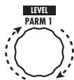
- To set the adjustment range for the parameter to be controlled, use parameter knob 2 (minimum value) and parameter knob 3 (maximum value).
The display changes as follows.
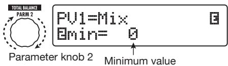
When parameter knob 2 is operated
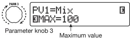
When parameter knob 3 is operated
HINT
- The available range setting depends on the parameter selected in step 4.
- It is also possible to set "min" to a higher value than "MAX". In that case, the parameter value will be minimum when the pedal is fully depressed and maximum when the pedal is fully raised.
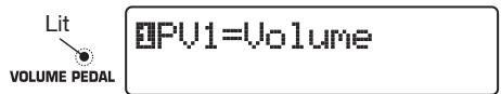
6. To use the expression pedal for switching the module on and off, turn parameter knob 4 and select "Switch:Enable".
When you turn parameter knob 4, the display changes as follows.

PU1=Mix 0Switch:Enable
Parameter knob 4
The expression pedal has a switch that is triggered when the pedal is pushed a bit further in the vertical direction, after the fully down position is reached. The module to which the selected parameter belongs will be switched on or off.
If you select "Disable" by turning parameter knob 4, module on/off switching will not be available.
HINT
- When "Volume" is the control target and "Enable" is selected, the volume pedal function can be switched on and off. The effect of on/off switching can be verified by checking the status of the [VOLUME PEDAL] LED to the left of the expression pedal.
- It is also possible to use the pedal normally for volume control and to switch a module on and off by pushing the pedal fully down. To achieve this, set the volume pedal on/off status, and the control target module on/off status to the opposite condition ( p.33) .
7. Repeat steps 3 - 6 to set the other control targets for the vertical direction in the same way.
8. To assign control targets for the horizontal direction, turn the [TYPE] knob to select one of the four horizontal direction control targets (PH1 to PH4).
The display changes as follows.
![ZOOM B91UT - To assign control targets for the horizontal direction, turn the [TYPE] knob to select one of the four horizontal direction control targets (PH1 to PH4). - 1](/content/2025/01/152193/images/d42155455abd698e715dcc4e6dad51efbb48b57a19a1b209c9290c5d155b9da0.jpg)
The operation steps for setting the horizontal direction control targets PH1 to PH4 are the same.
9. Repeat steps 4 - 5 to set the parameter and minimum and maximum values for the control target.
NOTE
In the horizontal direction of the expression pedal, no module on/off switching is possible.
10. Repeat steps 8 - 9 to set the other control targets for the horizontal direction in the same way.
NOTE
It is also possible to specify the same parameter for more than one control target, but in some cases, extreme parameter value changes may lead to noise. This is not a defect.
11. When all settings for expression pedal have been made, press the [EXIT] key.
The unit returns to manual mode or play mode.
NOTE
Pedal settings will be lost when you select a new patch. Be sure to store the patch if you want to keep the changes ( p, 27) .
HINT
- The expression pedal incorporates a stopper for movement in the horizontal direction. If horizontal action is not required, using the stopper may be preferable.
- Switching between horizontal action enable/ disable can be assigned to a function foot switch ( p, 36) .
Using the expression pedal while switching functions
The expression pedal push-down switch can be used during play to switch between two sets of settings. As an example, this section describes how to set up the B9.1ut so that the pedal normally works as a volume pedal, but enables a special effect when pushed fully down.
(1) Perform steps 1 - 5 of "Assigning control targets to the expression pedal" (p. 31) and assign parameters for the vertical expression pedal action (PV1 - PV4).
First, assign "Volume" as control target PV1 and set the volume pedal function to on. When the function is on, the [VOLUME PEDAL] LED to the left of the expression pedal is lit.
Next, for the alternative volume pedal function, assign the "Sense" parameter of the WAH/EFX1 module as control target PV2.
PU2=Sense wAH:Autoliah
(2) Perform step 6 of "Assigning control targets to the expression pedal" to set all control targets to "Enable".
When the setting is completed, press the [EXIT] key to return to the previous mode.
(3) Verify that the volume pedal function is on and set the control target selected in step 1 (WAH/EFX1 module in this example) to off.
In this condition, the WAH/EFX1 module will be off when the volume pedal function is on. When you press the volume pedal fully down, the volume pedal function is switched off and the WAH/EFX1 module will be on.
Adjusting the expression pedal
The expression pedal of the B9.1ut is adjusted for optimum operation at the factory, but sometimes, readjustment may be necessary. If the action of the pedal seems to be insufficient, or if a large change occurs even if the pedal is only lightly pushed, adjust the pedal as follows.
1. Hold down the [PEDAL] key while turning on power to the unit.
The display indication changes as follows.
![ZOOM B91UT - Hold down the [PEDAL] key while turning on power to the unit. - 1](/content/2025/01/152193/images/650d33ee79872232573e3827cb200e0b11bfb41d1c0305add0378c9b25ca89f1.jpg)
2. With the expression pedal fully raised, press the [STORE/SWAP] key.
![ZOOM B91UT - With the expression pedal fully raised, press the [STORE/SWAP] key. - 1](/content/2025/01/152193/images/936943b20027574c61c47d8461213c1ff0c7db7fa3de6c0700626e537ec89122.jpg)
The display indication changes as follows.
![ZOOM B91UT - With the expression pedal fully raised, press the [STORE/SWAP] key. - 2](/content/2025/01/152193/images/116d2e3b705c63e4cf0c76af964b796b68fb482b3a30b460d617346a3326aa6a.jpg)
PDL Calibration
PEDAL-U...MAX
- Push the expression pedal fully down in the vertical direction and then lift your foot off the pedal and press the [STORE/SWAP] key.
![ZOOM B91UT - With the expression pedal fully raised, press the [STORE/SWAP] key. - 3](/content/2025/01/152193/images/637c6608042c5c60ff53c59cda7671f0ba8cd93965cc4954d91071af859d66f1.jpg)
The display indication changes as follows.
![ZOOM B91UT - With the expression pedal fully raised, press the [STORE/SWAP] key. - 4](/content/2025/01/152193/images/9e9e557189fd7df9dad2cc665fa303012f2d936f7d9116d3728373f88f7abd93.jpg)
PDL Calibration PEDAL-H..min
- Lift the stopper of the expression pedal to secure the pedal. Then turn the pedal fully to the right and press the [STORE/SWAP] key.
![ZOOM B91UT - With the expression pedal fully raised, press the [STORE/SWAP] key. - 5](/content/2025/01/152193/images/cf3fe7f3859f888f7d779566fe3de864c2e7c5f87cd6e90ec99fd4d31ceac632.jpg)
(2) Turn pedal fully to the right
The display indication changes as follows.
![ZOOM B91UT - With the expression pedal fully raised, press the [STORE/SWAP] key. - 6](/content/2025/01/152193/images/079962a72e6ebfc4d0a24a9a2914162db6d801ce85cfc9d0216671a2fd522209.jpg)
PDL Calibration PEDAL-H...MAX
- Push the stopper of the expression pedal down, turn the pedal fully to
the right, and press the [STORE/ SWAP] key.
![ZOOM B91UT - With the expression pedal fully raised, press the [STORE/SWAP] key. - 7](/content/2025/01/152193/images/f8e48fcfc77472a114d6bdbcf66c6368dfbf5ea9bfb941479b20aa4f4e09a32c.jpg)
The adjustment is completed, and the unit returns to the play mode.
HINT
If the indication "ERROR" appears, return to step 2 and repeat the procedure.
Using an external expression pedal
If you connect an optional expression pedal (FP01/FP02) to the CONTROL IN jack of the B9.1ut, you can use it as a separate volume pedal, freeing up the built-in expression pedal for other functions.
- Plug the cable of the external expression pedal into the CONTROL IN jack and turn power to the B9.1ut on.
- Operate the external expression pedal in manual mode, play mode, or edit mode.
The volume level changes.
HINT
The external expression pedal always operates as volume pedal. It can also be used as a controller for sending MIDI messages ( p.46) .
Adjusting the expression pedal torque
Adjusting horizontal torque for expression pedal
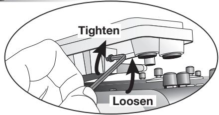
- Fully raise the expression pedal at the right side of the unit.
Pedal adjustment fitting is visible on rear of expression pedal.
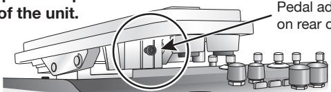
- Insert a 3mm size hex wrench into the fitting on the outside of the panel. To increase pedal firmness, turn the wrench clockwise. To decrease pedal firmness, turn the wrench counterclockwise.
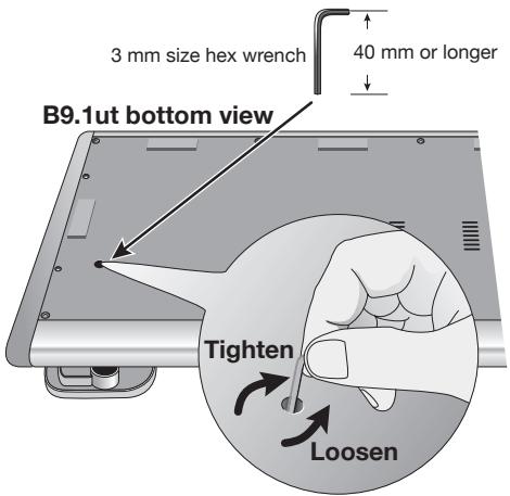
Adjusting vertical torque for expression pedal
- Turn power to the B9.1ut off, disconnect the AC adapter from the unit, and turn the unit upside down.
- Insert a 3 mm size hex wrench into the hole on the underside of the expression pedal. To increase pedal firmness, turn the wrench clockwise. To decrease pedal firmness, turn the wrench counterclockwise.

- The expression pedal of the B9.1ut is designed for operation with one foot. When the pedal is fully turned to the right, pushing it strongly down, hitting it, or otherwise exerting strong force on it will damage the pedal. Be sure to operate the pedal only within its designated range.
- If you loosen the pedal too much, the internal screw may come off, and you will no longer be able to tighten the pedal. Perform this operation with care.
- If the screw should have come off inside the unit, contact your dealer or an authorized Zoom service station.
- Never try to open the cabinet of the B9.1ut yourself, and never turn power to the B9.1ut on if the screw is unsecured inside the unit. Otherwise the electronic circuitry may be seriously damaged.
Using the Foot Switches
This section explains how to assign individual functions to the function foot switches 1 - 3 and how to select the modules that are assigned to the foot switches 1 - 4 in manual mode.
Making settings for function foot switches
The function foot switches 1 - 3 can be used to perform user-assigned functions. To assign a function to a switch, proceed as follows.
1. In manual mode or play mode, select the patch.
HINT
Functions assigned to the function foot switches 1 - 3 are specific to each patch.
2. Press the [FOOT SW] key.
The display changes as follows.
![ZOOM B91UT - Press the [FOOT SW] key. - 1](/content/2025/01/152193/images/d73d722703851bffc045e7205aa0fe36ddbba783983997ed0c773f8dea275543.jpg)
FuncSW1 Assign EBypass: BypassOnOff
HINT
The function foot switch setting is included in the TOTAL/FUNCTION module for the patch. The above display can also be called up by pressing the [TOTAL/FUNCTION] key in the effect module key section and then turning the [TYPE] knob.
3. Use the parameter knobs 1 - 3 to select the function for function foot switches 1 - 3.
The parameter knob number corresponds to the function foot switch number.
For example, when you turn parameter knob 2, the display changes as follows.
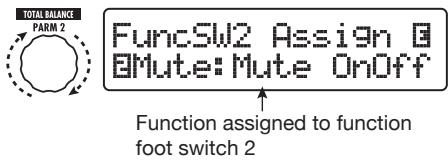
■ When parameter knob 2 is turned
The following functions can be assigned to function foot switches 1-3.
- BypassOnOff, Mute OnOff
The function foot switch toggles the bypass mode and mute mode between on and off. In either mode, the tuning display appears.
- ManualMode
The function foot switch toggles between play mode and manual mode.
BPM TAP
The function foot switch can be used to specify the individual tempo for a patch ( p. 38). When the switch is pressed repeatedly, the interval between the last four presses is detected and averaged automatically, and the result is used the new tempo setting.
HINT
Using the tempo set here, specific parameters (Time and Rate) can be synchronized in note units ( p.38) .
Delay Tap
The function foot switch can be used to specify the Time parameter for the DELAY module.
HINT
- While BPM TAP specifies the tempo for an individual patch, Delay TAP uses the foot switch operation interval to directly set the
Time parameter value (delay time).
- To use Delay TAP, the DELAY module must be active for that patch.
Hold Delay
The function foot switch toggles hold delay between on and off. When you press the function foot switch in a patch for which hold delay is active, the hold function is turned on and the current delay sound is repeated. Pressing the function foot switch once more cancels hold, and the delay sound will decay naturally (see the following illustration).
HINT
To use HOLD DELAY, the DELAY module must be active for that patch.
Delay Mute
The function foot switch toggles DELAY module inpututing between on and off.
HINT
To use Delay Mute, the DELAY module must be active for that patch.
Hold Synth
The function foot switch toggles Hold Synth between on and off. When this function is assigned and the function foot switch is pressed for a patch where Hold Synth is enabled, the function becomes on and the current bass sound is held. Pressing the function foot switch once more releases the hold condition, and the bass sound stops.
HINT
To use the Hold Synth function, "MonoSyn" or "4VoiceSyn" must be selected as effect type in the PRE-AMP module of the patch.
COMP OnOff, WAH OnOff, ExLopOnOff, ZNR OnOff, AMP OnOff, EQ OnOff, CAB OnOff, MOD OnOff, DELAYOnOff, REV OnOff
The function foot switch toggles the respective module between on and off.
TunerDsply
The function foot switch calls up the tuner display without bypassing the effects.
P-H Disable
The function foot switch enables/disables the horizontal action of the expression pedal.
HINT
- When "BPM TAP" or "Delay TAP" is selected, the function foot switch LED flashes red in sync with the BPM setting.
- It is also possible to assign the same function to multiple function foot switches.
4. After selecting a function to assign to the function foot switch, press the [EXIT] key.
NOTE
Any changes in assignment settings will be lost when you select a new patch. Be sure to store the patch if you want to keep the changes ( p) 27).
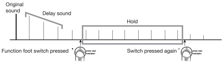
[Hold Delay]

Assigning modules to foot switches 1 - 4
In manual mode, the foot switches 1 - 4 can be used to turn specific modules on and off. This section explains how to assign modules to the switches.
1. In manual mode or play mode, select the patch.
HINT
Functions assigned to the foot switches 1 - 4 are specific to each patch.
2. Press the [FOOT SW] key twice.
The display changes as follows.
![ZOOM B91UT - Press the [FOOT SW] key twice. - 1](/content/2025/01/152193/images/aa6e9a18e5f9927a84b37fbb458830f7bd3e94f2ea638f5aa87378e4bb890ec6.jpg)
HINT
The foot switch 1-4 setting is included in the TOTAL/FUNCTION module for the patch. The above display can also be called up by pressing the [TOTAL/FUNCTION] key in the effect module key section and then turning the [TYPE] knob.
3. Use the parameter knobs 1-4 to select the function for foot switches 1-4.
The parameter knob number corresponds to the foot switch number.
For example, to select a module to assign to foot switch 1, turn parameter knob 1.
The following modules can be assigned to the respective foot switches.
- Foot switch 1
COMP module (CMP) or WAH/EFX1 module (WAH)
- Foot switch 2
PRE-AMP module (AMP) or EXT LOOP module (ExL)
- Foot switch 3
The names of the two modules that can be assigned to each foot switch are printed on the panel to the right of the switch. The currently selected module is indicated by the respective LED which is either lit (module on) or flashing (module off).
NOTE
Any changes in assignment settings will be lost when you select a new patch. Be sure to store the patch if you want to keep the changes ( p) 27).

Specifying the tempo for a patch
The B9.lut lets you specify a tempo for each individual patch and synchronize specific parameters to this tempo in note units. This section explains how to specify and use the tempo setting for a patch.
1. In manual mode or play mode, select the patch.
2. Press the [TOTAL/FUNCTION] effect module key.
The tempo setting for each patch is part of the [TOTAL/FUNCTION] module.
When you press the [TOTAL/FUNCTION] effect module key, the display changes as follows.
![ZOOM B91UT - Press the [TOTAL/FUNCTION] effect module key. - 1](/content/2025/01/152193/images/b81f3fc1d8bd0f046461c1618a75e1c3d122d2bd91543bd9f82e71a89940a7f6.jpg)
TOTAL: PatchLevel
Level = 80
3. Turn parameter knob 3 to set the tempo.
The tempo setting range is 40 - 250.
When you turn parameter knob 3, the display changes as follows.

TOTAL:TempoEBPM = 120
Parameter knob 3
4. To synchronize a parameter to the specified tempo, select the effect type and effect parameter to synchronize, and select the note symbol as the setting value for the parameter.
The setting value for effect parameters which support tempo synchronization can be selected in note units, using the patch specific tempo as a reference.
For example, the Time parameter of the effect type TapeEcho in the MOD/EFX2 module supports patch specific tempo synchronization. To use this capability, turn the respective parameter knob from the maximum setting (2000) further clockwise until a note symbol appears on the display.
HINT
In the section "Effect Types and Parameters" ( pages 64-79), parameters which support tempo synchronization are indicated by a note symbol.
5. Select a parameter value by selecting a note symbol.
The following note settings for parameters which support tempo synchronization are available.
| £ | Thirty-second note |
| £ | Sixteenth note |
| 3 | Quarter triplet note |
| n | Dotted sixteenth note |
| h | Eighth note |
| 3 | Half triplet note |
| h | Dotted eighth note |
| d | Quarter note |
| n | Dotted quarter note |
| x2 | Quarter note x 2 |
| : | : |
| x20 | Quarter note x 20 |
NOTE
The actual available setting range depends on the parameter.
For example, when you have selected the eighth note setting, the Time parameter will be set to a value that corresponds to an eighth note in the patch specific tempo. When the tempo is changed, the delay time also changes accordingly.
NOTE
Depending on the combination of tempo setting and selected note symbol, the maximum of the parameter setting range (such as 2000 ms) may be exceeded. In such a case, the value is automatically halved (or set to 1/4 if the range is still exceeded).
6. When the tempo and parameter setting is complete, press the [EXIT] key.
The unit returns to manual mode or play mode.
Store the patch as necessary.
The above procedure uses the tempo set in step 3 as reference for the note setting made in step 5. If the "BPM TAP" function is assigned to one of the function foot switches 1 - 3 , you can specify the tempo with your foot during a performance and have the parameter change accordingly.
Using the Effect Loop
The EXT LOOP SEND/RETURN jacks on the rear panel of the B9.lut allow connection of a compact effect, rack-mount effect or similar. Settings for external effect on/off and send/return level can be stored as part of a patch.
This section explains how to use the effect loop.
1. Connect the external effect to the EXT LOOP SEND/RETURN jacks.
HINT
When connecting to an effect that has a rated input level of +4 dBm (rack-mount effect or similar), set the EXT LOOP GAIN switch to the "+"dBm" setting. When connecting to an instrument effect or a compact effect, use the "-10 dBm" setting.
NOTE
- The external effect should always be set to ON, to allow effect on/off switching at the B9.lut.
- If the external effect allows adjustment of mixing ratio between original sound and effect sound (such as a reverber or delay), set the original sound to 0% and the effect sound to 100% .
2. Select the patch in manual mode or play mode.
HINT
Effect loop settings can be made individually for each patch.
3. Press the [EXT LOOP] effect module key to activate edit mode.
Effect loop settings are made in the EXT LOOP module.
The display changes as follows.
EXT LOOP
EXT LOOP
SendLevel= 50
NOTE
When "EXT LOOP Module Off" is shown, the EXT LOOP module is currently turned off. Press the [EXT LOOP] key once more to turn the module on.
4. Use parameter knob 1 to adjust the level of the signal sent from the B9.1ut to the external effect (send level).

EXT LOOP
SendLevel=80
Parameter knob 1
HINT
If the input level at the external effect is not sufficient even with the send level turned up, or if distortion occurs at the external effect input even with the send level turned down, check whether the EXT LOOP GAIN switch setting is appropriate.
5. Use parameter knob 2 to adjust the level of the signal sent from the external effect to the B9.1ut (return level).
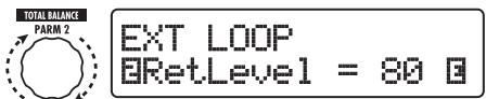
Parameter knob 2
- Use parameter knob 3 to adjust the level balance between the signal returned from the external effect and the internal signal of the B9.1ut (dry level).
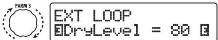
Parameter knob 3
HINT
- If the external effect is the type that mixes effect sound to the original sound (such as a reverb, delay, or chorus), adjust the level balance between original sound and effect sound by adjusting the return level and dry level.
-
If the external effect is the type that processes the input signal for output (such as a compressor or EQ unit), the dry level should normally be set to 0 and the signal level should be adjusted with the return level parameter.
-
When the effect loop settings have been made, press the [EXIT] key.
The unit returns to manual mode or play mode.

- Store the patch as necessary.
When you next call up the stored patch, the external effect settings will also become effective again.
HINT
If the external effect supports MIDI based program switching, the B9.lut can control the effect by sending program change messages. In this way, patch switching at the B9.lut and program switching at the B9.lut can be synchronized ( p.43) .
MIDI Usage Examples
This section describes the various MIDI functions of the B9.1ut.
What you can do with MIDI
The B9.1ut lets you use MIDI in various ways, as described below.
- Send and receive patch switching information via MIDI
When you switch patches at the B9.1ut, the MIDI OUT connector carries the corresponding MIDI messages (program change, or bank select + program change). Similarly, when a valid MIDI message is received at the MIDI IN connector, the B9.1ut will perform the corresponding patch switch action.
This makes it possible to have patches at the B9.1ut switched automatically under control of a MIDI sequencer, or link operation of the B9.1ut to patch switching at other MIDI enabled devices.
- Send and receive pedal/switch/key operation information via MIDI
When you operate specific keys and foot switches of the B9.lut, or operate the expression pedal, the MIDI OUT connector carries the corresponding MIDI messages (control change). Similarly, when a valid MIDI message is received at the MIDI IN connector, the B9.lut will vary the corresponding parameter.
This makes it possible to use the B9.1ut as a real-time controller for other MIDI enabled devices, or alter effect parameters and module on/off status under control of a MIDI sequencer, synthesizer, or other MIDI enabled device.
Exchange patch data between two B9.1ut units via MIDI
The patch data of the B9.1ut can be output as MIDI messages (system exclusive), for copying to another B9.1ut.
Selecting the MIDI channel
To enable correct sending and receiving of program change, control change and other MIDI messages, the MIDI channel (1 - 16) setting of the B9.1ut and the other MIDI device must be matched. To set the MIDI channel at the B9.1ut, proceed as follows.
1. In manual mode or play mode, press the [SYSTEM] key.
The SYSTEM menu for parameters that apply to all patches appears.
![ZOOM B91UT - In manual mode or play mode, press the [SYSTEM] key. - 1](/content/2025/01/152193/images/5642b3a72360bf04a604dfe3b7d15ebe8173c4fd94e33eab839432af92bd3dc2.jpg)
PICKUP Sel 1/29
EACTIVE
2. Turn the [TYPE] knob to select the "MIDI Rx Ch" (MIDI receive channel) parameter.
![ZOOM B91UT - Turn the [TYPE] knob to select the "MIDI Rx Ch" (MIDI receive channel) parameter. - 1](/content/2025/01/152193/images/9d31a3f867c5319585ce9c6884107bfd835b9e8c4f481775df12ef6e4e468805.jpg)
MIDI 4/29 IRx Ch=1
[TYPE] knob
3. Turn parameter knob 1 to select the MIDI channel (1 - 16) on which the B9.1ut will receive MIDI messages.

MIDI 4/29
IRx Ch=3
Parameter knob 1
- Turn the [TYPE] knob to select the "MIDI Tx Ch" (MIDI transmit channel) parameter.

MIDI 5/29
DTx CH=1
[TYPE]knob
- Turn parameter knob 1 to select the MIDI channel (1 - 16) on which the B9.1ut will send MIDI messages.
- When the setting is complete, press the [EXIT] key to cancel the SYSTEM menu.
If a setting was changed, the indication "Store...?" appears on the display, to allow you to store the changes.

Store...?
Y[STORE] N[EXIT]
If no setting was changed, the unit returns to the previous mode.
- Press the [STORE/SWAP] key to save the changes.

The MIDI channel setting is accepted, and the unit returns to manual mode or play mode.
By pressing the [EXIT] key, you can abort the changes and return to the previous mode without saving.
Sending and receiving patch switching information via MIDI (program change)
You can send and receive patch changing information of the B9.1ut via MIDI as program change or bank select + program change messages.
There are two ways (program change modes) for doing this, as described below.
- Direct mode
With this method, you use a combination of MIDI bank select and program change messages to specify the patch.
HINT
- Bank select is a MIDI message type for specifying the sound category of a synthesizer or similar. It is used in combination with program change messages.
-
Normally, bank select is specified in two parts, using the MSB (most significant byte) and LSB (least significant byte) value.
-
Mapping mode
With this method, you use only the MIDI program change messages to specify the patch. A program change map is used to assign program change numbers 0 - 127 to patches, and patches are then selected using the mapping information. With this method, a maximum of 128 patches can be specified.
■ Enable program change send/receive
The procedure for enabling send/receive of program change (+ bank select) messages is described below.
- In manual mode or play mode, press the [SYSTEM] key.

PICKUP Sel 1/29
ACTIVE
- To enable the B9.1ut to receive program change (+ bank select) messages, turn the [TYPE] knob to bring up the "MIDI PC Rx" (receive program change) parameter, and turn parameter knob 1 to select the "ON" setting.

MIDI 8/29
BPC Rx =ON
Parameter knob 1
- To enable the B9.1ut to send program change (+ bank select) messages, turn the [TYPE] knob to bring up the "MIDI PC Tx" (send program change) parameter, and turn parameter knob 1 to select the "ON" setting.

MIDI 9/29
BPC Tx =ON
Parameter knob 1
- When the setting is complete, press the [EXIT] key to cancel the SYSTEM menu.
If a setting was changed, the indication "Store...?" appears on the display, to allow you to store the changes.

Store...? Y[STORE] N[EXIT]
If no setting was changed, the unit returns to the previous mode.
- Press the [STORE/SWAP] key to save the changes.
The setting is accepted, and the unit returns to manual mode or play mode.
By pressing the [EXIT] key, you can abort the changes and return to play mode without saving.
Using direct mode
By using a combination of MIDI bank select and program change messages, you can specify a patch directly.
NOTE
Before carrying out the following steps, verify that the send/receive MIDI channel setting of the B9.lut is as required ( p.42) , and that send/receive of program change messages is enabled ( p.43) .
- In play mode, press the [SYSTEM] key.

PICKUP Sel 1/29
BACTIVE
- Turn the [TYPE] knob to bring up the "MIDI PCMODE" (program change mode) parameter.

MIDI PCMODE 6/29
DIRECT
[TYPE]knob
- Verify that "DIRECT" is selected as program change mode.
If not, turn parameter knob 1 to change the indication to "DIRECT". This enables direct selection of all patches using bank select and program change messages.
HINT
For information on which bank number/program change number is assigned to each patch, see the list at the end of this manual ( p.83)
- When the setting is complete, press the [EXIT] key to cancel the SYSTEM menu.
If a setting was changed, the indication "Store...?" appears on the display, to allow you to store the changes. If no setting was changed, the unit returns to the previous mode.
5. Press the [STORE/SWAP] key to save the changes.
The setting is accepted, and the unit returns to manual mode or play mode.
By pressing the [EXIT] key, you can abort the changes and return to play mode without saving.
6. To send and receive program change (+ bank select) messages, connect the B9.1ut and the other MIDI device as follows.
[Example for sending program change (+ bank select) messages]
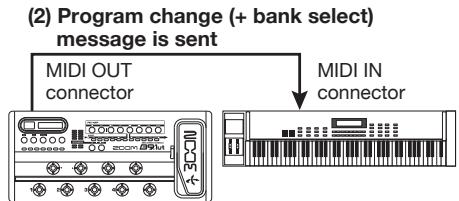
(1) When a patch at the B9.1ut is switched...
[Example for receiving program change (+ bank select) messages]
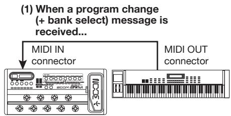
(2) Patch at the B9.1ut is switched.
NOTE
When the external MIDI device sends only a bank select message to the B9.1ut, no change occurs. The next time the B9.1ut receives a program change, the most recent bank select instruction will be used.
Using mapping mode
In this mode, a program change map is used to assign patches, allowing patches to be specified by using program change messages only.
NOTE
Before carrying out the following steps, verify that the send/receive MIDI channel setting of the B9.lut is as required ( p.42) , and that send/receive of program change messages is enabled ( p.43) .
1. In manual mode or play mode, press the [SYSTEM] key.
![ZOOM B91UT - In manual mode or play mode, press the [SYSTEM] key. - 1](/content/2025/01/152193/images/458a0e408d488b44aa6cf3de61f74d90446ff7ce6120106fba63fdf4b65bcb9b.jpg)
PICKUP Sel 1/29
ACTIVE
2. Turn the [TYPE] knob to bring up the "MIDI PCMODE" (program change mode) parameter.
![ZOOM B91UT - Turn the [TYPE] knob to bring up the "MIDI PCMODE" (program change mode) parameter. - 1](/content/2025/01/152193/images/d7b3f7856dcc32d2ccce6a455b411086cba9d7e8d44d7fbd642c7f2f79e69a6d.jpg)
MIDI PCMODE 6/29
IDIRECT
[TYPE]knob
3. Turn parameter knob 1 to bring up the indication "Mapping".
Patches can now be specified using program change messages according to the program change map.

MIDI PCMODE 6/29
IMAPPING
Parameter knob 1
4. Turn the [TYPE] knob to bring up the "PC MAP" (program change map) parameter.
Using this display, you can assign any patch of the B9.1ut to a program change number from 0 - 127.
![ZOOM B91UT - Turn the [TYPE] knob to bring up the "PC MAP" (program change map) parameter. - 1](/content/2025/01/152193/images/c025b0f7b3b1f5dd068ac4ca90d3afb0e950a95b1cea8693b9fefe34a8ba0a94.jpg)
- To assign a patch to a program change number, proceed as follows.
(1) Turn parameter knob 1 until the program change number to use is shown on the top line of the display.
![ZOOM B91UT - Turn the [TYPE] knob to bring up the "PC MAP" (program change map) parameter. - 2](/content/2025/01/152193/images/8ca18d4d382f4684a223734472dc5b36f0f57736c484a530695502da3fa3c78f.jpg)
(2) Use parameter knobs 2 and 3 to select the group name/bank number and patch number to assign to the program change number selected in step (1).
Parameter knob 2
![ZOOM B91UT - Turn the [TYPE] knob to bring up the "PC MAP" (program change map) parameter. - 3](/content/2025/01/152193/images/3326e85094cc0ddba1c41bb4ac6576f644b9d6a6bb60f30d9554615c66cda31e.jpg)
Parameter knob 3
![ZOOM B91UT - Turn the [TYPE] knob to bring up the "PC MAP" (program change map) parameter. - 4](/content/2025/01/152193/images/1ec264f048c6867d3f6423a6726fd44236e689128900fd2f6aa357826815ae83.jpg)
PC MAP Prg: 10
BBrk: U900Pat: 4
(3) Repeat these steps for other program change numbers.
6. When the setting is complete, press the [EXIT] key to cancel the SYSTEM menu.
If a setting was changed, the indication "Store...?" appears on the display, to allow you to store the changes.
If no setting was changed, the unit returns to the previous mode.
- Press the [STORE/SWAP] key to save the changes.
The setting is accepted, and the unit returns to manual mode or play mode.
By pressing the [EXIT] key, you can abort the changes and return to play mode without saving.
- To send and receive program change messages, proceed as described in step 6 of "Using direct mode" ( p.44).
The program change (+ bank select) messages sent by the unit are the same in direct mode and mapping mode. For information on which bank number/program change number is assigned to each patch, see the list at the end of this manual ( p,83) .
Sending and receiving pedal/switch/key operation information via MIDI (control change)
The B9.1ut allows sending and receiving control change messages via MIDI. These messages govern actions such as operating the expression pedal, and switching modules or bypass/mute on and off with keys and foot switches. Each action can be assigned its own control change number (cc#).
■ Enable control change send/receive
The procedure for enabling send/receive of control change messages is described below.
- In manual mode or play mode, press the [SYSTEM] key.
![ZOOM B91UT - Turn the [TYPE] knob to bring up the "PC MAP" (program change map) parameter. - 5](/content/2025/01/152193/images/7e9f17228c314e01f1b751b676469afe041e74f51e31a04af620e5ba0757aab1.jpg)
- To enable the B9.1ut to receive control change messages, turn the [TYPE] knob to bring up the "MIDI CTRL Rx" (receive control change) parameter, and turn parameter knob 1 to select the "ON" setting.
![ZOOM B91UT - Turn the [TYPE] knob to bring up the "PC MAP" (program change map) parameter. - 6](/content/2025/01/152193/images/cb4bc0b34140319134ef876a77d50401591da707afd185ad88123f63bc7bd0eb.jpg)
MIDI 10/29
CTRL Rx=ON
Parameter knob 1
- To enable the B9.1ut to send control change messages, turn the [TYPE] knob to bring up the "MIDI CTRL Tx" (send control change) parameter, and turn parameter knob 1 to select the "ON" setting.
![ZOOM B91UT - Turn the [TYPE] knob to bring up the "PC MAP" (program change map) parameter. - 7](/content/2025/01/152193/images/dc1ea467df9b4537f6a75844d26e2572f82359962e8a398417240ccc8b80240d.jpg)
MIDI 11/29
CTRL Tx=ON
Parameter knob 1
- When the setting is complete, press the [EXIT] key to cancel the SYSTEM menu.
If a setting was changed, the indication "Store...?" appears on the display, to allow you to store the changes.
If no setting was changed, the unit returns to the previous mode.
![ZOOM B91UT - Turn the [TYPE] knob to bring up the "PC MAP" (program change map) parameter. - 8](/content/2025/01/152193/images/1610c2790045e1291d9dda75f763378ce1d29746902a8f3dbf86ad7c3a4e7d8a.jpg)
Store...?
Y[STORE] N[EXIT]
- Press the [STORE/SWAP] key to save the changes.
The setting is accepted, and the unit returns to manual mode or play mode. By pressing the [EXIT] key, you can abort the changes and return to play mode without saving.
■Assigning control change numbers
You can assign control change numbers to the expression pedal and keys of the B9.1ut as follows.
NOTE
Before carrying out the following steps, verify that the send/receive MIDI channel setting of the B9.lut is as required ( p.42) , and that send/receive of control change messages is enabled ( p.46) .
- In manual mode or play mode, press the [SYSTEM] key.

PICKUP Sel 1/29
ACTIVE
- Turn the [TYPE] knob to bring up the display for assigning a control change number.
Operations to which a control change number can be assigned are listed in the table on the next page.
For example, to assign the control change number 11 (cc#11) to the vertical direction of the built-in expression pedal, the following display is used.

MIDI cc# 14/29
PEDAL-U=11
[TYPE] knob
HINT
The control change number assignment always applies both for sending and receiving.
- Turn parameter knob 1 to specify a control change number.

MIDI cc# 14/29 PEDAL- v = ?
Parameter knob 1
| Display | Control target | Default cc# | cc# setting range |
| CTRL IN | Expression pedal operation | 7 | OFF, 1 - 5, 7 - 31, 64 - 95 |
| PEDAL-V | Expression pedal operation, vertical direction | 11 | OFF, 1 - 5, 7 - 31, 64 - 95 |
| PEDAL-H | Expression pedal operation, horizontal direction | 12 | OFF, 1 - 5, 7 - 31, 64 - 95 |
| COMP | COMP module on/off | 64 | OFF, 64 - 95 |
| WAH/EFX1 | WAH/EFX1 module on/off | 65 | OFF, 64 - 95 |
| EXT LOOP | EXT LOOP module on/off | 66 | OFF, 64 - 95 |
| ZNR | ZNR module on/off | 67 | OFF, 64 - 95 |
| PRE-AMP | PRE-AMP module on/off | 68 | OFF, 64 - 95 |
| EQUALIZER | EQ module on/off | 69 | OFF, 64 - 95 |
| CABINET | CABINET module on/off | 70 | OFF, 64 - 95 |
| MOD/EFX2 | MOD/EFX2 module on/off | 71 | OFF, 64 - 95 |
| DELAY | DELAY module on/off | 72 | OFF, 64 - 95 |
| REVERB | REVERB module on/off | 73 | OFF, 64 - 95 |
| MUTE | Mute mode on/off | 74 | OFF, 64 - 95 |
| BYPASS | Bypass mode on/off | 75 | OFF, 64 - 95 |
4. Assign control change numbers to other operations in the same way.
5. When the setting is complete, press the [EXIT] key to cancel the SYSTEM menu.
If a setting was changed, the indication "Store...?" appears on the display, to allow you to store the changes.
If no setting was changed, the unit returns to the previous mode.
6. Press the [STORE/SWAP] key to save the changes.
The setting is accepted, and the unit returns to manual mode or play mode.
By pressing the [EXIT] key, you can abort the changes and return to play mode without saving.
7. To send and receive control change messages, connect the B9.1ut and the other MIDI device as follows.
Example for sending control change messages
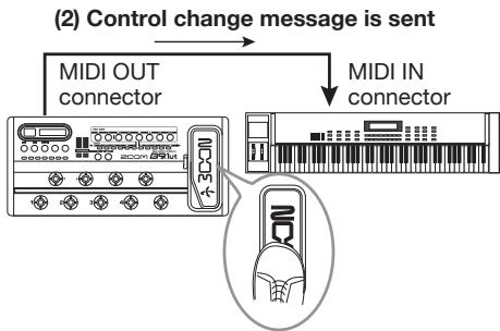
(1) When the expression pedal or switches and keys at the B9.1ut are operated...
Control change values sent from the B9.1ut change as follows.
- When the built-in/external expression pedal is operated
The value of the assigned control change number is varied continuously over the range of 0 - 127. For the built-in expression pedal, two control change messages can be sent simultaneously, for vertical direction and horizontal direction movement.
- When module on/off switching is performed
When the module is set to on, the value 127 of the control change number is sent. When the module is set to off, the value 0 of the control change number is sent.
- When bypass/mute on/off switching is performed
When bypass/mute is set to on, the value 127 of the control change number is sent. When bypass/mute is set to off, the value 0 of the control change number is sent.
Example for receiving control change messages
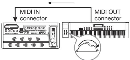
(1) When a control change message is received...
(2) The same operation as when the respective expression pedal or switch or key at the B9.1ut is operated occurs.
According to the control change value received, the B9.1ut status and parameter values change as follows.
- When control change for built-in/ external expression pedal is received
The value of the parameter assigned to the pedal changes according to the control change value (0 - 127).
- When control change for module on/off is received
If control change value is between 0 and 63, the module is switched off. If control change value is between 64 and 127, the module is switched on.
- When control change for bypass/mute on/off is received
If control change value is between 0 and 63,
bypass/mute is switched off. If control change value is between 64 and 127, bypass/mute is switched on.
Sending pedal synth playing information via MIDI (note on/note off)
When the pedal synth function is enabled, foot switch playing information can be sent as note on/note off messages via MIDI
1. In manual mode or play mode, press the [SYSTEM] key.
![ZOOM B91UT - In manual mode or play mode, press the [SYSTEM] key. - 1](/content/2025/01/152193/images/b5c13f00c8ae4c14af83a9677d028b0d1d738119d096f3c411b27195128cb3c8.jpg)
PICKUP Sel 1/29
BACTIVE
2. Turn the [TYPE] knob to bring up the "NOTE ON Tx" (send note on/ note off) parameter on the display.
![ZOOM B91UT - Turn the [TYPE] knob to bring up the "NOTE ON Tx" (send note on/ note off) parameter on the display. - 1](/content/2025/01/152193/images/258f51ebc742b251c8d4e4ea9e72dc458a00679763031318037fbbafde1ee4d8.jpg)
MIDI 12/29
NOTE ON Tx=ON
[TYPE]knob
3. Turn parameter knob 1 to select "ON" or "OFF".
When ON was selected, playing with the pedal synth function will result in note on/note off messages being sent.
The pedal synth function has two operation modes for producing sound: TG (trigger) and HD (hold).
The differences in note on/note off sending operation are as follows.
TG
Note on is sent when the foot switch is pressed and note off is sent when the foot switch is released.
HD
Note on is sent when the foot switch is
pressed, and note off is sent when the foot switch is pressed once more.
HINT
For more information on the pedal synth function, see page 55.
4. When the setting is complete, press the [EXIT] key to cancel the SYSTEM menu.
If a setting was changed, the indication "Store...?" appears on the display, to allow you to store the changes.
If no setting was changed, the unit returns to the previous mode.
5. Press the [STORE/SWAP] key to save the changes.
The setting is accepted, and the unit returns to manual mode or play mode.
By pressing the [EXIT] key, you can abort the changes and return to play mode without saving.
HINT
To send note on/notes off information, make connections as shown in step 7 of "Assigning control change numbers" ( p.47)

Sending and receiving B9.1ut patch data via MIDI
The patch data stored in a B9.lut can be sent and received as MIDI messages (system exclusive). When two B9.lut units are connected via a MIDI cable, this allows copying of patch data from the sending unit to the receiving unit.
NOTE
When patch data are received, all existing patch data in the B9.1ut will be overwritten. Perform the following steps with care, to avoid accidentally overwriting important data.
1. Connect the MIDI OUT connector on the source B9.1ut to the MIDI IN connector on the target B9.1ut
using a MIDI cable.
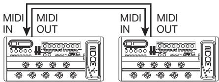
The steps at the target B9.1ut and source B9.1ut are explained separately below.
Target B9.1ut
2. Set the B9.1ut to manual mode or play mode.
If the unit is in another mode or shows another display, press the [EXIT] key to return to the manual mode or play mode.
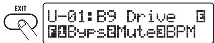
Source B9.1ut
- Set the B9.1ut to manual mode or play mode and press the [SYSTEM] key.

- Use the [TYPE] knob to bring up the "BulkDumpTx" (bulk dump transmit) parameter on the display.
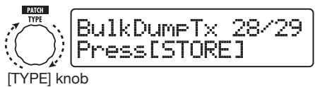
5. Press the [STORE/SWAP] key.
The sending of patch data begins.
While the target B9.1ut is receiving data, the display changes as follows.
PatchDataDumpRx Receive Patch...
When the patch data send/receive process is completed, the source B9.1ut return to the SYSTEM menu and the target B9.1ut returns to the previous mode.
HINT
The web site of ZOOM Corporation (http://wwwzoomo.co.jp) has editor/librarian software available for download. Using this software, you can store patch data of the B9.1ut on a computer.
Other Functions
Using the ARRM function
The B9.1ut incorporates an innovative feature called ARRM (Auto-Repeat Real-time Modulation) which uses various internally generated control waveforms to cyclically modify effect parameters. You can select for example a triangular waveform and apply it to the wah frequency as a control target. The resulting effect is shown below.
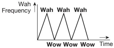
This section explains the use of the ARRM feature.
1. In manual mode or play mode, select the patch.
HINT
The ARRM settings can be made separately for each patch.
2. Press the [TOTAL/FUNCTION] effect module key to switch to edit mode, and then turn the [TYPE] knob to bring up the indication "ARRM" on the display.
The ARRM function settings are part of the TOTAL/FUNCTION module. The display shows the following information.
![ZOOM B91UT - Press the [TOTAL/FUNCTION] effect module key to switch to edit mode, and then turn the [TYPE] knob to bring up the indication "ARRM" on the display. - 1](/content/2025/01/152193/images/0f061da46a413ba8d7de162e173c54af2f76ca18dfe053bed0511f8a01d006cd.jpg)
3. Turn parameter knob 1 to select the control target parameter.
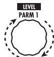
Parameter knob 1
As you turn parameter knob 1, the effect parameter, effect type, and effect module changes.
HINT
- The parameters that can be selected as control targets are the same as can be selected for operation by the expression pedal. See the section "Effect Types and Parameters" ( p.64 - 79) .
- When "NOT Assign" is displayed, no parameter is assigned as control target and the ARRM function is disabled.
4. To set the adjustment range for the parameter to be controlled, use parameter knob 2 (minimum value) and parameter knob 3 (maximum value).
The settings selected with parameter knobs 2 and 3 determine the value when the control waveform reaches minimum value and maximum value.
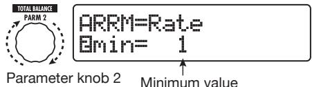

The difference between a parameter setting range of 0 (minimum) - 100 (maximum) and 20 (minimum) - 80 (maximum) is evident from the graph below.
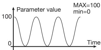
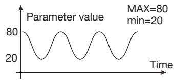
HINT
- The available range setting depends on the parameter.
- It is also possible to set "min" to a higher value than "MAX". In that case, the control change direction will be reversed.
5. When the control target and parameter range have been set, turn the [TYPE] knob clockwise to bring up the following display.
This display lets you select the control waveform and cycle.
![ZOOM B91UT - When the control target and parameter range have been set, turn the [TYPE] knob clockwise to bring up the following display. - 1](/content/2025/01/152193/images/28a056e2b9cc72a63c7f2c6dec02b97c390170a29792ddbc8eae7f45afdcf95e.jpg)
ARRM=Rate
Uwave=Upsaw
[TYPE]knob
The ARRM function has a total of five parameters. To set parameters 4 and 5, turn the [TYPE] knob to bring up the above display and then use parameter knobs 1 and 2 to make the setting. To return to the setting condition for parameters 1 - 3, turn the [TYPE] knob counterclockwise to return to the previous display. If the ARRM control target is set to "Not Assign", this display does not appear.
6. Turn parameter knob 1 to select the control waveform type.
The display changes as follows.

ARRM=Rate
Dwave=Triangle
Parameter knob 1 Control waveform type
Available waveforms are shown below.
| 1 | Rising sawtooth (Up Saw) | |
| 2 | Rising fin (Up Curve) | |
| 3 | Falling sawtooth (Down Saw) | |
| 4 | Falling fin (Down Curve) |
| 5 | Triangle (Triangle) | |
| 6 | Square triangle (Square Tri) | |
| 7 | Sine wave (Sine) | |
| 8 | Square wave (Square) | |
7. Turn parameter knob 2 to select the control waveform cycle.
The display changes as follows.

ARRM=Rate Sync=Jx2
Parameter knob 2
The control waveform cycle uses the patch specific tempo ( p. 38) as reference and is displayed as eighth note, quarter note, or quarter note x numeral (see table on page 39).
The numeral after x(2 - 20) indicates the duration of a cycle in multiple quarter notes. When "2" is selected, the control waveform changes in a cycle interval that corresponds to half a note of the patch specific tempo. When "4" is selected, the cycle is 4 beats (1 measure of a 4/4 time signature).
HINT
When the "ARRM BPM" parameter is assigned to the expression pedal, the reference tempo for the ARRM function (0 - 250) can be controlled with the pedal. For information on how to assign control targets to the expression pedal, see page 31. The expression pedal movement will not change the patch specific tempo.
8. When the ARRM setting is complete, press the [EXIT] key.
The unit returns to manual mode or play mode.
Store the patch as necessary.
NOTE
Any changes in ARRM settings will be lost when you select a new patch. Be sure to store the patch if you want to keep the changes ( p, 27) .

Using the sound-on-sound function
The B9.1ut can record a phrase of up to 5.4 seconds duration during play and use it for loop playback to create a sound-on-sound effect. The steps for this function are described below.
1. In manual mode or play mode, press the [DELAY] key.
The B9.1ut switches to edit mode. If the indication "Module Off" is shown, press the [DELAY] key once more to turn the module on.
2. Turn the [TYPE] knob to select the effect type "SOS" (sound-on-sound).
The display changes as follows.
![ZOOM B91UT - Turn the [TYPE] knob to select the effect type "SOS" (sound-on-sound). - 1](/content/2025/01/152193/images/de89a6cd9ecd32ed85dd1455298e0131fc8dfc7536cc5121f00b88d988e978c5.jpg)
When "SOS" is selected as effect type, the LED of function foot switch 2 is out (nothing is recorded), and the LED of function foot switch 3 flashes (recording standby condition).
Function foot switches 2 and 3 operate as follows.
- Function foot switch 2
Stop record/play, clear recorded content, set tempo
- Function foot switch 3
Start record/play, cancel recording mode
3. Turn parameter knob 1 to set the recording duration.
The recording duration can be selected as follows.
Mn
Specify the duration by pushing the function foot switch twice in the desired interval (max.
5.4 seconds).
Note symbol
Use the patch-specific tempo ( p. 38) as reference and set recording duration in note units.
HINT
When nothing is recorded (LED of function foot switch 2 is out), you can use function foot switch 2 to set the tempo of the patch. When the switch is pressed repeatedly, the interval between the last four presses is detected and averaged automatically, and the result is used the new tempo setting.
4. Turn parameter knob 2 to specify the effect sound mixing ratio.
Raising this value will increase the effect sound level during loop playback after recording.

Parameter knob 2
5. When the sound-on-sound settings are complete, press the [EXIT] key.
The unit returns to manual mode or play mode.
Store the patch as necessary.
6. While playing your bass, press function foot switch 3 to start recording.
The LED of function foot switch 3 lights up in red, and recording starts.
The recording operation will depend on the settings made in step 3.
"Mn" is selected
After recording starts, it will continue until you press function foot switch 3 once more, or until 5.4 seconds have elapsed. After recording is finished, loop playback starts.
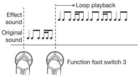
Note symbol is selected
After recording starts, it will continue for the selected duration and then stop automatically. However, if the combination of tempo and note symbol setting results in a duration longer than 5.4 seconds, recording will stop when half of the duration has elapsed. (If this is still longer than 5.4 seconds, recording will stop after one fourth of the duration has elapsed.) After recording is finished, loop playback starts.
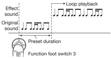
HINT
- When there are recorded data, the LED of function foot switch 2 will be lit in red.
- During loop playback, the LED of function foot switch 3 will flash in green.
7. To record another layer, press function foot switch 3 again during loop playback.
The LED of function foot switch 3 lights up in orange, the sound-on-sound recording starts. You can listen to the loop playback and record a new bass phrase.
When you press function foot switch 3 once more, recording stops and the unit returns to loop playback only.
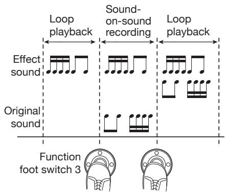
8. To stop loop playback, press function foot switch 2.
HINT
To start loop playback again, press function foot switch 3.
9. To clear the recorded contents, hold down function foot switch 2.
When the recorded content has been cleared (LED of function foot switch 2 goes out), release the switch.
NOTE
- The recorded content cannot be stored.
- When you change the effect type or switch a module on or off, the recorded content is cleared.
- When the pedal synth function (see next section) is enabled, the sound-on-sound function becomes unavailable.
Using the pedal synth function
The B9.1ut offers a pedal synth function which lets you use the foot switches on the front panel to play a synthesizer bass sound. The steps for this function are described below.
1. In manual mode or play mode, press the [PRE-AMP] key.
The B9.1ut switches to edit mode. If the
indication "Off" is shown, press the [PRE-AMP] key once more to turn the module on.
2. Turn the [TYPE] knob to select the effect type "PedalSyn" (pedal synth).
The display changes as follows.
![ZOOM B91UT - Turn the [TYPE] knob to select the effect type "PedalSyn" (pedal synth). - 1](/content/2025/01/152193/images/b00174cb8b8cc12a93527d756b6bb11d0ce109cea8016b5e0896bb91a7f33d9a.jpg)
[TYPE]knob
When "PedalSyn" is selected as effect type, the foot switches on the front panel are assigned only to the pedal synth function.
NOTE
When the pedal synth function is enabled, the "Loop" and "SOS" functions of the DELAY module become unavailable.
HINT
Function foot switch 2 serves to turn the PRE
AMP module off. The other foot switches are used to produce pedal synth sound.
3. Turn parameter knob 3 to select the pedal synth scale and the sound generation method.
The display changes as follows.
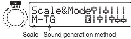
Parameter knob 1
Three types of pedal synth scales are available: M (Major), m (Minor), C (Chromatic). The sound arrangement with each scale is shown in the illustration below.
The pedal synth function has two operation modes for producing sound: TG (trigger) and HD (hold).
The differences in operation are as follows.
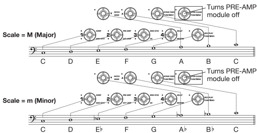
Foot switch sound arrangement with different scales (for C3 keynote)
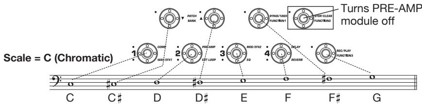
TG
Pedal synth sound is produced when the foot switch is pressed and the sound then decays gradually.
HD
Pedal synth sound is produced when the foot switch is pressed and the sound continues until the same foot switch is pressed once more or another foot switch is pressed.
4. To specify the keynote (the sound produced by foot switch 1), turn parameter knob 2.
The display changes as follows.


Parameter knob 2
The keynote is expressed as an alphanumeric indication (setting range: C1 - B3). The letter and # (sharp) symbol indicate the range in note names, and the numeral the range in octave units. C1 is Do three octaves below center C, and B3 is Ti immediately below center C.
The keynote set here is assigned to foot switch 1. The assignment of the remaining foot switches depends on the scale as specified in step 3.
5. To change the pedal synth sound, turn parameter knob 3. To adjust the balance between original sound and effect sound, turn parameter knob 4.
For details about each parameter, see the section "Effect Types and Parameters" ( p. 70).
6. When the pedal synth settings are complete, press the [EXIT] key.
The unit returns to manual mode or play mode.
Store the patch as necessary.
When the pedal synth function was enabled, the indication in manual mode and play mode changes as follows.
![ZOOM B91UT - When the pedal synth settings are complete, press the [EXIT] key. - 1](/content/2025/01/152193/images/a5c01a6dbae38166bca9058795852cef43b86c29f0741706dc535614b9782de9.jpg)
7. To play the pedal synth sounds, press the foot switches except for function foot switch 2.
HINT
The pedal synth sound is processed by the effects after the PRE-AMP module, and the bass sound is processed by the effects other than the PRE-AMP module. For information on the effect link sequence, see page 63.
8. To return all front panel foot switches to normal operation, press function foot switch 2.
The PRE-AMP module goes off and all foot switches revert to normal operation.
Using the B9.1ut as audio interface for a computer
By connecting the USB port of the B9.1ut to a USB port on a computer, the B9.1ut can be used as an audio interface with integrated AD/DA converter and effects. The operating environment conditions for this type of use are as follows.
Compatible operating system
Windows XP, Windows Vista
Mac OS X (10.2 and later)
Quantization 16-bit
Sampling frequencies 32 kHz / 44.1 kHz / 48 kHz
HINT
With each of the operating systems listed above, the B9.1ut will function as an audio interface
simply by connecting the USB cable. There is no need to install any special driver software.
NOTE
The USB port of the B9.1ut only serves for sending and receiving audio data. For MIDI messages, use the MIDI IN/OUT connectors.
To use the B9.1ut as an audio interface for the computer, connect the USB port of the B9.1ut to a USB port on the computer. The B9.1ut will be recognized as an audio interface.
In this condition, the sound of a bass guitar connected to the INPUT jack of the B9.1ut can be processed with the effects of the B9.1ut and then be recorded on the audio tracks of a DAW (Digital Audio Workstation) software application on the computer (see Figure 1 below).
When performing playback with the DAW application, the playback sound from the audio tracks is mixed with the bass guitar sound processed by the effects of the B9.1ut and appears at the OUTPUT jack of the B9.1ut (see Figure 2 below).
If required, the guitar signal after effect processing can be muted during playback (see
Figure 3 below). For details, see the next section. For details on recording and playback, refer to the documentation of the DAW application.
NOTE
- If the DAW application has an echo back function (input signal during recording is supplied directly to an output), this must be disabled. If recording is carried out with the echo back function on, the output signal may sound as if processed by a flanger effect, or the direct output signal may sound delayed.
- Use a high-quality USB cable and keep the connection as short as possible.
Muting the direct output when using a USB connection
When the B9.1ut is connected to a computer and used as an audio interface, the signal appearing at the OUTPUT jack after effect processing may be muted if required. To do this, proceed as follows.
1. In manual mode or play mode, press the [SYSTEM] key.
The SYSTEM menu for parameters that apply to
![ZOOM B91UT - In manual mode or play mode, press the [SYSTEM] key. - 1](/content/2025/01/152193/images/f81a9b63433ec83e452700ee332970f9016ad4b45ecfe54526106d8c8233bf05.jpg)
Fig. 1: Signal flow during recording
![ZOOM B91UT - In manual mode or play mode, press the [SYSTEM] key. - 2](/content/2025/01/152193/images/ea25e0e0fe040595d6779aa848b075246f638159ab93dc48429c05f7d5a52a0c.jpg)
Fig. 2: Signal flow during playback (1)
Fig. 3: Signal flow during playback (2)
![ZOOM B91UT - In manual mode or play mode, press the [SYSTEM] key. - 3](/content/2025/01/152193/images/51e30bbf455d07ea203c551e7fafb23b1a0d90debcd79344e0046de79906683a.jpg)
all patches appears.
![ZOOM B91UT - In manual mode or play mode, press the [SYSTEM] key. - 4](/content/2025/01/152193/images/8518d92213a117f8d9ecf0393c9f56e5246e5b7977a5da89ccc0732cba8f5e24.jpg)
PICKUP Sel 1/29
BACTIVE
- Turn the [TYPE] knob to bring up the indication for the "USB Monitor" parameter (output mode when USB connection is used).
![ZOOM B91UT - In manual mode or play mode, press the [SYSTEM] key. - 5](/content/2025/01/152193/images/829b536ee886e1c47417283c75706a4c07bc7f22757eb67ab606ca26982c4163.jpg)
USB Monitor 3/29 USB+DIRECT
[TYPE]knob
- Turn parameter knob 1 to select one of the following settings.
- USB+DIRECT
The signal after effect processing appears directly at the OUTPUT jacks also when USB connection is used.
USB Only
The signal after effect processing is muted, and only the signal sent from the computer via the USB connection is output.
- When the setting is complete, press the [EXIT] key.
HINT
The USB Monitor setting is returned to the default (USB+DIRECT) at the next power-down/power-up cycle.
Changing the default reference pitch of the tuner
You can specify the reference pitch of the built-in tuner that will be established at power-on.
- In manual mode or play mode, press the [SYSTEM] key.
The SYSTEM menu for parameters that apply to all patches appears.
- Turn the [TYPE] knob to bring up the indication shown below.

Tuner Calib 2/29 144Hz
[TYPE]knob
- Turn parameter knob 1 to change the reference pitch.
- When the setting is complete, press the [EXIT] key.
If the setting was changed, the indication "Store...?" appears on the display, to allow you to store the changes.
If the setting was not changed, the unit returns to the previous mode.
- Press the [STORE/SWAP] key to store the new setting.
If you press the [EXIT] key, the change will be discarded and the unit returns to the previous mode.
Use as a direct box
The BALANCED OUT connectors on the rear panel let you use the B9.1ut as a direct box for sending the bass signal directly to a PA mixer or recording console. (Gain: 0 dB, output impedance: 200 ohms, HOT-COLD)
To use this function, connect the BALANCED OUT connectors of the B9.1ut to the PA mixer or recording console, using XLR balanced cables. If the signal causes distortion in the input stage of the other equipment, set the OUTPUT GAIN switch of the B9.1ut to "-10 dB". At the same time, you can also connect the OUTPUT jack to a bass amplifier for monitoring.
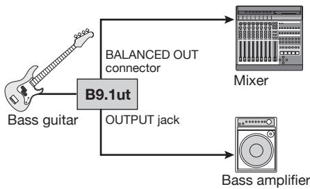
If you use the BALANCED OUT R connector, The [PRE/POST] switch lets you control the type of signal supplied as direct output. To use the signal after effect processing, select the "POST" position (switch engaged). To use the signal before effect processing, select the "PRE" position (switch disengaged). The Accelerator is active also if the "PRE" setting is selected.

When the BALANCED OUT connectors are used to connect the B9.1ut to a PA mixer or similar, ground loops (electrical signal loop that can occur when multiple components in a system are grounded separately) may lead to hum noise. In such a case, set the GROUND switch to the "LIFT" position (switch engaged). Often this will eliminate or reduce the hum.

Checking the B9.1ut version
To check the system version of your B9.1ut, proceed as follows.
1. In manual mode or play mode, press the [SYSTEM] key.
The SYSTEM menu for parameters that apply to all patches appears.
![ZOOM B91UT - In manual mode or play mode, press the [SYSTEM] key. - 1](/content/2025/01/152193/images/1d44dd66374fdb0009818e3c68006ba4c195e300dc6c9ee09d0c7123e8aac077.jpg)
PICKUP Sel 1/29
BACTIVE
2. Turn the [TYPE] knob to bring up
the "System Version" indication.
The current system version is shown on the second line of the display.
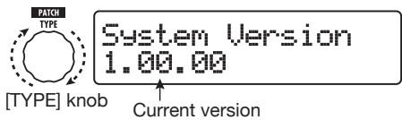
HINT
The system version is also briefly shown during power-up of the B9.1ut.
3. After checking the system version, press the [EXIT] key.
The unit returns to the previous mode.
![ZOOM B91UT - After checking the system version, press the [EXIT] key. - 1](/content/2025/01/152193/images/51c9807b052ccd20cba79433924e3ebcbaf83a1d408b3d227ad7b04f084cc515.jpg)
Editor/librarian software for the B9.1ut
ZOOM CORPORATION makes an editor/ librarian software application for the B9.1ut available for download on its web site.
To use the software, the computer must have a MIDI interface, and a connection must be established between the MIDI IN/MIDI OUT connectors of the computer and the MIDI OUT/MIDI IN connectors of the B9.lut. The software then makes it possible to store patch data of the B9.lut on the computer, edit the data, and copy edited patch data back to the B9.lut.
Web site of ZOOM CORPORATION
http://wwwzoomo.co.jp
Linking Effects
The patches of the B9.1ut can be thought of as ten serially linked effect modules, as shown in the illustration below. You can use all effect modules together or selectively set certain modules to off to use just specific effect modules.
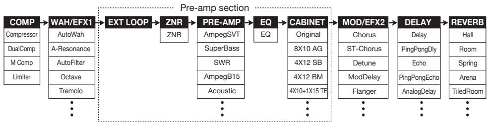
For some effect modules, you can select an effect type from several possible choices. For example, the MOD/EFX2 module comprises Chorus, Flanger, and other effect types from which you can choose one.
The five-module series EXT LOOP, ZNR, PRE-AMP, EQ, and CABINET functions as a virtual preamplifier.

Using the Pickup Select function
The B9.lut incorporates a Pickup Select function that optimizes the signal level to match the type of pickup in use. When starting to use the B9.lut or when changing the bass guitar, you should choose a suitable pickup setting as described below.
- In manual mode or play mode, press the [SYSTEM] key.

PICKUP Sel 1/29
IPASSIVE
- Turn parameter knob 1 to select one of the following settings.
PASSIVE
Select this setting if you are using a bass guitar with an integrated passive pickup.
ACTIVE
Select this setting if you are using a battery-powered preamplifier or a bass guitar with an integrated active pickup.
3. When the setting is complete, press the [EXIT] key.
If the setting was changed, the indication "Store...?" appears on the display, to allow you to store the changes.
If the setting was not changed, the unit returns to the previous mode.
4. Press the [STORE/SWAP] key to store the new setting.
If you press the [EXIT] key, the change will be discarded and the unit returns to the previous mode.
![ZOOM B91UT - Press the [STORE/SWAP] key to store the new setting. - 1](/content/2025/01/152193/images/e0cccb69052231cd60e0c12ce4822a650833cc53f51ba55e811098faacfb9e19.jpg)
Changing the insert position of the pre-amp section and WAH/EFX1 module
The B9.1ut allows you to change the insert position of the five modules making up the pre-amp section (EXT LOOP, ZNR, PRE-AMP, EQ, CABINET) and the WAH/EFX1 module. This will result in changes to the effect action and tone.
Changing the insert position of the WAH/EFX1 module
To change the insert position of the WAH/EFX1 module, call up the Position parameter and set it to "Befr" (before pre-amp section) or "Aftr" (after pre-amp section). The Position parameter can be used when the Octave, Tremolo, Defret, Splitter, or X-Vibe effect type is not selected.
1. In manual mode, play mode, or edit mode, press the [WAH/EFX1] key.
![ZOOM B91UT - In manual mode, play mode, or edit mode, press the [WAH/EFX1] key. - 1](/content/2025/01/152193/images/fda3310ba950cd1424258244a1602a9729dcdd5d48499c245f219473f052e066.jpg)
2. Turn the [TYPE] knob and select an effect type other than Octave, Tremolo, Defret, Splitter, or X-Vibe.
3. Turn parameter knob 1 to select "Befr" (before pre-amp section) or "Aftr" (after pre-amp section).

WAH:Autoliah Position Aftr
Parameter knob 1
4. When the setting is complete, press the [EXIT] key.
The unit returns to the previous mode. To enable the changed setting, be sure to store the patch ( p.27).
Changing the insert position of the pre-amp section
To change the insert position of the pre-amp section, call up the Chain parameter and set it to "Pre" (before MOD/EFX2 module) or "Post" (after DELAY module). The Chain parameter can be used with all effect types except for bass synth effects.
1. In manual mode, play mode, or edit mode, press the [PRE-AMP] key.
The display changes as follows.
![ZOOM B91UT - In manual mode, play mode, or edit mode, press the [PRE-AMP] key. - 1](/content/2025/01/152193/images/ccee6a04fcf57a2f0952ae9351b4d92279e71cd3974d429deb5f87c4bfea1d9c.jpg)
PRE-AMP AmPe9SUT
宁中宁中
2. Turn the [TYPE] knob and select an effect type other than a bass synth effect.
3. Turn parameter knob 3 to select "Pre" (before MOD/EFX2 module) or "Post" (after DELAY module).
The display changes as follows.

Chain Post
宁1111 1111
Parameter knob 3
4. When the setting is complete, press the [EXIT] key.
The unit returns to the previous mode. To enable the changed setting, be sure to store the patch ( p. 27).
NOTE
- When the "Pre" setting is selected as pre-amp section insert position, the signal after the MOD/EFX2 module is processed fully in stereo. When you select "Post", the signal is processed in the pre-amp section in mono.
- When a synthesizer effect type (StdSyn, SynTk, V-Syn, MonoSyn, 4VoiceSyn, PedalSyn) has been selected for the PRE-AMP module, the Chain parameter cannot be used. With a synthesizer effect type, the synth sound is processed by the effects after the PRE-AMP
module, and the bass sound is processed by the effects other than the PRE-AMP module.
The module lineup with different settings for the WAH/EFX1 module and pre-amp section insertion position is shown below.
Pre-amp section = PRE, WAH/EFX1 = Befr
Pre-amp section

Pre-amp section = PRE, WAH/EFX1 = Aftr
Pre-amp section

Pre-amp section = POST, WAH/EFX1 = Befr
Pre-amp section

Pre-amp section = POST, WAH/EFX1 = Afftr
Pre-amp section

- WAH/EFX1 = Befr (When synthesizer effect type is selected)
Pre-amp section
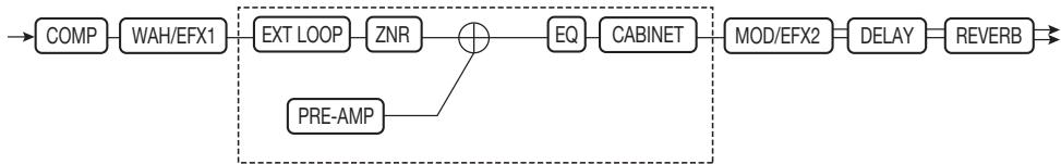
- WAH/EFX1 = Aftr (When synthesizer effect type is selected)
Pre-amp section
Effect Types and Parameters
How to read the parameter table
Tempo sync
The note symbol () in the table indicates that the parameter can be synchronized to the patch specific tempo. If you select the note symbol as a value for the parameter when making the setting at the B9.1ut, the parameter value will be synchronized to the patch specific tempo in note units ( p.38) .
Expression pedal
The pedal symbol () in the table indicates that the parameter can be controlled with the built-in expression pedal. If you select the parameter as control target when making the setting at the B9.1ut ( p. 31), the expression pedal will adjust the parameter in real time when the patch is selected. Parameters with the pedal symbol can also be selected as control targets for the ARRM function.
Delay tap/hold delay/delay mute/hold synth
The TAP, HOLD, MUTE, and SYNTH indications in the table show that the respective function foot switch 1 - 3 can be used to specify the delay time (TAP), toggle hold delay on and off (HOLD), toggle delay mute input between on and off (MUTE), and toggle hold synth on and off (SYNTH). These functions apply to the DELAY module (TAP, HOLD, MUTE) or the PRE-AMP module (SYNTH).
To use these functions, the respective function must be assigned to the function foot switch 1 - 3 ( p. 36) and the respective effect type must be enabled.
| COMP | COMP (Compressor) module | ||||||
| This module includes a compressor which attenuates high-level signal components and boosts low-level signal components to keep the signal level within a certain range, and a limiter which controls signal peaks to keep the signal level below a certain limit. | |||||||
| Compressor | |||||||
| This is a compressor which stresses the sense of attack. | |||||||
| PARM1 | PARM2 | PARM3 | PARM4 | ||||
| Sense | 0-50 | Attack | 1-10 | Release | 1-10 | Level | 2-100 |
| Adjusts the compressor sensitivity. Higher setting values result in higher sensitivity. | Adjusts the compressor attack rate. | Adjusts the delay between the point where the signal level falls below the threshold level and the compressor release. | Adjusts the signal level after passing the module. | ||||
| DualComp (Dual Compressor) | |||||||
| This is a compressor which allows separate settings for the low frequency and high frequency range. | |||||||
| PARM1 | PARM2 | PARM3 | PARM4 | ||||
| SenseHi | 0-50 | SenseLo | 0-50 | XoverFreq | 1-10 | Level | 2-100 |
| Adjusts the compression depth in the high frequency range. | Adjusts the compression depth in the low frequency range. | Adjusts the crossover point between the high frequency and low frequency range. | Adjusts the signal level after passing the module. | ||||
| M Comp (M Compressor) | |||||||
| This is a compressor with natural operation. | |||||||
| PARM1 | PARM2 | PARM3 | PARM4 | ||||
| Threshold | 0-50 | Ratio | 1-10 | Attack | 1-10 | Level | 2-100 |
| Adjusts the reference signal level for the compressor action. | Adjusts the compression ratio of the compressor. | Adjusts the compressor attack rate. | Adjusts the signal level after passing the module. | ||||
| Limiter | |||||||
| This is a limiter that suppresses signal peaks above a certain reference level. | |||||||
| PARM1 | PARM2 | PARM3 | PARM4 | ||||
| Threshold | 0-50 | Ratio | 1-10 | Release | 1-10 | Level | 2-100 |
| Adjusts the reference signal level for the limiter action. | Adjusts the compression ratio of the limiter. | Adjusts the delay between the point where the signal level falls below the threshold level and the limiter release. | Adjusts the signal level after passing the module. | ||||
| WAH/EFX1 | WAH/EFX1 (Wah/Effects 1) module | ||||||
| This module comprises wah and filter effects as well as special effects such as ring modulator and octave. | |||||||
| AutoWah | |||||||
| This effect varies wah in accordance with picking intensity. | |||||||
| A-Resonance (Auto Resonance) | |||||||
| This effect varies the resonance filter frequency in accordance with picking intensity. | |||||||
| The above two effect types have the same parameters. | |||||||
| PARM1 | PARM2 | PARM3 | PARM4 | ||||
| Position | Befr, Aftr | Sense | -10-10 | Resonance | 0-10 | DryMix | 0-100 |
| Selects the connection position of the WAH/EFX1 module. Available settings are "Befr" (before pre-amp section) or "Aftr" (after pre-amp section). | Adjusts the effect sensitivity. Negative values result in downward filter action. | Adjusts the intensity of the effect character. | Adjusts the original sound mixing ratio. | ||||
| AutoFilter | |||||||
| This is a resonance filter with a sharp envelope. | |||||||
| PARM1 | PARM2 | PARM3 | PARM4 | ||||
| Position | Befr, Aftr | Sense | -10-10 | Peak | 0-10 | DryMix | 0-100 |
| See "A-Resonance (Auto Resonance)". | Adjusts the effect sensitivity. | Adjusts the Q value of the filter. | Adjusts the original sound mixing ratio. | ||||
| Octave | |||||||
| This effect adds a one-octave lower component to the original sound. | |||||||
| PARM1 | PARM2 | PARM3 | PARM4 | ||||
| OctLevel | 0-100 | DryLevel | 0-100 | Tone | 0-10 | Level | 2-100 |
| Adjusts the level of the one-octave lower sound component. | Adjusts the level of the original sound. | Adjusts the tonal quality of the one-octave lower sound component. | Adjusts the signal level after passing the module. | ||||
| Tremolo | |||||||
| This effect periodically varies the volume level. | |||||||
| PARM1 | PARM2 | PARM3 | PARM4 | ||||
| Depth | 0-100 | Rate | 0-50 | Wave | Up, Down, Tri | Clip | 1-10 |
| Adjusts the modulation depth. | Adjusts the modulation rate. | Sets the modulation waveform to "Up" (rising sawtooth), "Down" (falling sawtooth), or "Tri" (triangular). | Controls the clip amount of the modulation waveform. Higher setting values result in stronger clipping of the waveform tips, giving a stronger effect. | ||||
| 4StagePhaser | |||||||
| This is a 4-stage phaser effect that produces a swooshing sound. | |||||||
| 8StagePhaser | |||||||
| This is an 8-stage phaser effect that produces a swooshing sound. Compared to the 4-stage phaser, the effect sound is more detailed. | |||||||
| The above two effect types have the same parameters. | |||||||
| PARM1 | PARM2 | PARM3 | PARM4 | ||||
| Position | Befr, Atrr | Rate | 0-50 | Resonance | -10-10 | Level | 2-100 |
| See "A-Resonance (Auto Resonance)" (→ p. 65). | Adjusts the modulation rate. | Adjusts the intensity of the effect character. | Adjusts the signal level after passing the module. | ||||
| FixedPhaser | |||||||
| This is a fixed phaser effect that has an equalizer-like sound. | |||||||
| PARM1 | PARM2 | PARM3 | PARM4 | ||||
| Position | Befr, Atrr | Frequency | 1-50 | Color | 1-4 | Level | 2-100 |
| See "A-Resonance (Auto Resonance)" (→ p. 65). | Adjusts the frequency to be emphasized. | Adjusts the sound color. | Adjusts the signal level after passing the module. | ||||
| RingModulate | |||||||
| This effect produces a metallic ringing sound. Adjusting the "Frequency" parameter results in a drastic change of sound character | |||||||
| PARM1 | PARM2 | PARM3 | PARM4 | ||||
| Position | Befr, Atrr | Frequency | 1-50 | Balance | 0-100 | Level | 2-100 |
| See "A-Resonance (Auto Resonance)" (→ p. 65). | Adjusts the modulation frequency. | Adjusts the balance between original sound and effect sound. | Adjusts the signal level after passing the module. | ||||
| Defret | |||||||
| Turns the sound from any bass guitar into a fretless bass sound. | |||||||
| PARM1 | PARM2 | PARM3 | PARM4 | ||||
| Sense | 0-30 | Tone | 1-50 | Color | 1-10 | Level | 2-100 |
| Adjusts the effect sensitivity. | Adjusts the tonal quality of the sound. | Adjusts the harmonics contents of the sound. Higher setting values result in stronger effect character. | Adjusts the signal level after passing the module. | ||||
| SlowAttack | |||||||
| This effect slows down the attack rate of the sound, resulting in a violin playing style sound. | |||||||
| PARM1 | PARM2 | PARM3 | PARM4 | ||||
| Position | Befr, Atrr | Time | 1-50 | Curve | 0-10 | Level | 2-100 |
| See "A-Resonance (Auto Resonance)" (→ p. 65). | Adjusts the rise time. | Adjusts the rising volume change curve. | Adjusts the signal level after passing the module. | ||||
Splitter
| This effect divides the signal into two bands (high/low) and lets you freely adjust the mixing ratio of the two bands. | |||||||
| PARM1 | PARM2 | PARM3 | PARM4 | ||||
| Hi Mix | 0-100 | Low Mix | 0-100 | Frequency | 80-2.5k | Level | 2-100 |
| Adjusts the mixing ratio of the high frequency band. | Adjusts the mixing ratio of the low frequency band. | Adjusts the crossover point between the high frequency and low frequency band. | Adjusts the signal level after passing the module. | ||||
| PedalVox | |||||||
| This simulation effect is modeled on vintage Vox pedal wah. | |||||||
| PedalWah | |||||||
| This is a pedal wah effect for bass guitar. | |||||||
The above two effect types have the same parameters.
| PARM1 | PARM2 | PARM3 | PARM4 | ||||
| Position | Befr, Atrr | Frequency | 1-50 | DryMix | 0-100 | Level | 2-100 |
| See "A-Resonance (Auto Resonance)" (→ p. 65). | Adjusts the frequency that is emphasized. When the expression pedal is not used, the effect is similar to a half open pedal. | Adjusts the original sound mixing ratio. | Adjusts the signal level after passing the module. | ||||
P-Resonance (Pedal Resonance)
| PAM1 | PARM2 | PARM3 | PARM4 | ||||
| Position | Befr,Afr | Frequency | 1-50 | Resonance | 0-10 | Level | 2-100 |
| See "A-Resonance (Auto Resonance) (→ p. 65). | Adjusts the modulation frequency. | Adjusts the intensity of the effect character. | Adjusts the signal level after passing the module. | ||||
X-Wah
| This effect allows cross-fading of original sound and effect sound (Vox type wah), using the pedal or another control source. Try assigning the vertical direction of the Z-pedal (PV1 - PV4) to the "Frequency" parameter and the horizontal direction (PH1 - PH4) to the "X-Fade" parameter. | |||||||
| PARM1 | PARM2 | PARM3 | PARM4 | ||||
| Position | Befr, Affr | Frequency | 1-50 | X-Fade | 0-100 | Level | 2-100 |
| See "A-Ronance (Auto Resonance)" (→ p. 65). | Adjusts the modulation frequency. | Adjusts the balance between original sound and effect sound. | Adjusts the signal level after passing the module. | ||||
X-Phaser
| This effect allows cross-fading of original sound and effect sound (phaser), using the pedal or another control source. Try assigning the vertical direction of the Z-pedal (PV1 - PV4) to the "Rate" parameter and the horizontal direction (PH1 - PH4) to the "X-Fade" parameter. | |||||||
| PARM1 | PARM2 | PARM3 | PARM4 | ||||
| Color | Bef1 - 4, Aft1 - 4 | Rate | 0 - 50 | X-Fade | 0 - 100 | Level | 2 - 100 |
| Selects the connection position and sound type. The "Bef1" - "Bef4" settings place the effect before the PRE-AMP module and the "Aft1" - "Aft4" settings after the PRE-AMP module. | Adjusts the modulation rate. | Adjusts the balance between original sound and effect sound. | Adjusts the signal level after passing the module. | ||||
X-Vibe (X Vibrato)
| This effect allows cross-fading of phaser sound and tremolo sound, using the pedal or another control source. Try assigning the vertical direction of the Z-pedal (PV1 - PV4) to the "PHA Rate" or "TRM Rate" parameter and the horizontal direction (PH1 - PH4) to the "X-Fade" parameter. | |||||||
| PARM1 | PARM2 | PARM3 | PARM4 | ||||
| PHA Rate | 0-50 | TRM Rate | 0-50 | X-Fade | 0-100 | Level | 2-100 |
| Adjusts the modulation rate of the phaser effect. | Adjusts the modulation rate of the tremolo effect. | Adjusts the balance between phaser sound and tremolo sound. | Adjusts the signal level after passing the module. | ||||
| EXT LOOP | EXT LOOP (External Loop) module | ||||
| This module controls an external effect connected to the EXT LOOP SEND/RETURN jacks. The external effect send level and return level and the B9.1ut internal signal level can be set separately for each patch. When this module is set to OFF, the external effect is defeated. | |||||
| PARM1 | PARM2 | PARM3 | |||
| SendLevel | 0 - 100 | RetLevel | 0 - 100 | DryLevel | 0 - 100 |
| Adjusts the external effect send level. | Adjusts the external effect return level. | Adjusts the volume of the original sound in the B9.1ut (the level that is input to the EXT LOOP module). | |||
| ZNR (Zoom Noise Reduction) module | ||
| This module serves for reducing noise during playing pauses. | ||
| ZNR (Zoom Noise Reduction) | ||
| ZOOM original noise reduction which reduces noise in playing pauses without affecting the overall tone. | ||
| PARM1 | ||
| Threshold | 1-16 | |
| Adjusts the ZNR sensitivity. For maximum noise reduction, set the value as high as possible without causing the sound to decay unnaturally. | ||
| PRE-AMP | PRE-AMP (Preamplifier) module | |
| This module provides simulation of 21 types of amplifiers and stomp boxes, as well as special effects such as bass synth etc. * Manufacturer names and product names mentioned in the table are trademarks or registered trademarks of their respective owners. The names are used only to illustrate sonic characteristics and do not indicate any affiliation with ZOOM CORPORATION. | ||
| AmpegSVT | SuperBass | |
| Simulation of the ultimate rock bass amp, the Ampeg SVT. | Simulation of the Marshall Super Bass that made rock history. | |
| SWR | AmpegB15 | |
| Simulation of the SWR SM-900, famous for its hi-fi sound. | Simulation of the Ampeg B-15 made famous by the Motown sound of the 1960s. | |
| Acoustic | Aguilar | |
| Simulation of the Acoustic 360 well known for its gutsy midrange. | Simulation of the Aguilar DB750 famous for its powerful sound. | |
| Bassman | Hartke | |
| Simulation of the Fender Bassman 100. | Simulation of the Hartke HA3500 famous for its aluminum cone. | |
| Polytone | G-Krueger | |
| Simulation of the Polytone Mini Brute with its distinct midrange, often used by Jazz musicians. | Simulation of the famous metal bass amp Gallien Krueger 800RB from the eighties. | |
| Trace | WalterWds | |
| Simulation of the Trace Elliot AH-500. | Simulation of the Walter Woods preferred by bassists who are keen on the original sound. | |
| TubePre | SansAmp | |
| ZOOM original tube preamplifier sound. | Simulation of the Sansamp Bass Driver DI, highly popular among bass players. | |
| TS9 | ODB-3 | |
| Simulation of the Tube Screamer used by many guitarists as a booster. | Simulates the ODB-3 overdrive bass machine from Boss. | |
| MXR D.I.+ | Fuzz Face | |
| Simulates the MXR Bass D.I.+ distortion channel. | Simulation of the Fuzz Face that made rock history with its zany look and smashing sound. | |
| MetalZone | BigMuff | |
| Simulation of the Boss MetalZone with long sustain and dynamic lower midrange. | Simulation of the Electro-Harmonix Big Muff preferred by famous artists for its fat, sweet fuzz sound. | |
DigiFuzz
High gain fuzz sound with strong character.
The above 21 effect types have the same parameters.
| GAIN | LEVEL | ||||
| Gain | 0-100 | Level | 1-100 | ||
| Adjusts the preamp gain (distortion depth). | Adjusts the signal level after passing the module. | ||||
| PARM1 | PARM2 | PARM3 | |||
| Tone | 0-30 | MixBal | 0-100 | Chain | Pre, Post |
| Adjusts the tonal quality of the sound. | Adjusts the balance between original sound and effect sound. | Selects the connection position of the pre-amp section. Available settings are "Pre" (before MOD/EFX2 module) or "Post" (after DELAY module). | |||
| StdSyn (Standard Synthesizer) | |||||
| ZOOM original bass synthesizer sound. | |||||
| GAIN | LEVEL | ||||
| Sense | 0-100 | Level | 1-100 | ||
| Adjusts the sensitivity for trigger detection. | Adjusts the signal level after passing the module. | ||||
| PARM1 | PARM2 | PARM3 | |||
| Variation | 1-4 | Tone | 0-10 | MixBal | 0-100 |
| Selects a synthesizer variation. | Adjusts the tonal quality of the sound. | Adjusts the balance between original sound and effect sound. | |||
| SynTik (Synthesizer Talk) | |||||
| This effect produces a synthesizer sound similar to a talking modulator producing vowels. | |||||
| GAIN | LEVEL | ||||
| Decay | 0-100 | Level | 1-100 | ||
| Adjusts the rate of sound change. | Adjusts the signal level after passing the module. | ||||
| PARM1 | PARM2 | PARM3 | |||
| Variation | iA, UE, UA, oA | Tone | 0-10 | MixBal | 0-100 |
| Selects a vowel variation. | Adjusts the tonal quality of the sound. | Adjusts the balance between original sound and effect sound. | |||
| V-Syn (Vintage Synthesizer) | |||||
| This effect produces a vintage bass synthesizer sound. | |||||
| GAIN | LEVEL | ||||
| Decay | 0-100 | Level | 1-100 | ||
| Adjusts the rate of sound change. | Adjusts the signal level after passing the module. | ||||
| PARM1 | PARM2 | PARM3 | |||
| Sense | 0-30 | Range | -10-10 | MixBal | 0-100 |
| Adjusts the sensitivity for trigger detection. | Adjusts the filter shift range. | Adjusts the balance between original sound and effect sound. | |||
| MonoSyn (Mono Synthesizer) | |||||
| This effect produces the sound of a monophonic (single-note playing) bass synthesizer that detects the pitch of the input signal. | |||||
| GAIN | LEVEL | ||||
| Decay | 0-100 | Level | 1-100 | ||
| Adjusts the rate of sound change. | Adjusts the signal level after passing the module. | ||||
| PARM1 | PARM2 | PARM3 | |||
| Variation | Saw, Pulse, PWM | Resonance | 0-10 | MixBal | 0-100 |
| Sets the waveform type to "Saw" (sawtooth), "Pulse" (square wave), or PWM (pulse width modulation resulting in fatter sound). | Adjusts the intensity of the effect character. | Adjusts the balance between original sound and effect sound. | |||
This effect type adds synthesizer harmony components to single notes played on the bass. The harmony components are determined by the Mode and Scale parameters.
4VoiceSyn (4-Voice Synthesizer)
| GAIN | |
| Attack | 0 - 10 |
| Adjusts the attack rate of the synthesizer sound. | |
| PARM1 | |
| Mode | 1 - 9 |
| Selects a harmony type from 1 - 9. | |
| LEVEL | |
| Level | 1 - 100 |
| Adjusts the signal level after passing the module. | |
| PARM2 | |
| Scale | 1, 2 |
| Selects a harmony variation. For each of the parameter 1 - 9 modes, two variations are available. (See illustration below.) | |
| PARM3 | |
| MixBal | 0 - 100 |
| Adjusts the balance between original sound and effect sound. | |
Note played on bass
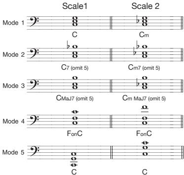
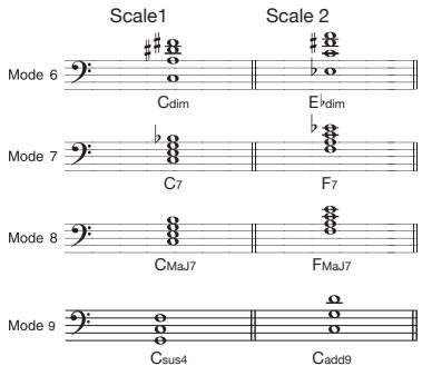
This is a synthesizer that can be played with the foot switches of the B9.1ut. When this effect type is selected, the foot switches operate differently from normal mode. For details, see page 56.
PedalSyn (Pedal Synthesizer)
| GAIN | |||
| Decay/Atk | 1-100 | ||
| Adjusts the rate of sound change. The target parameter is Decay in trigger mode and Attack in hold mode. | |||
| PARM1 | PARM2 | ||
| Scale&Mode | M-TG, m-TG, C-TG, M-HD, m-HD, C-HD | Key | C1-B3 |
| Selects the scale (M/m/C) and the sound generation mode (TG/HD) (→ p. 56). | Selects a keynote for pedal synth playing. | ||
| LEVEL | |
| Level | 1 - 100 |
| Adjusts the signal level after passing the module. | |
| PARM3 | |
| Variation | Saw0 - 9, Pulse0 - 9, PWM0 - 9 |
| Selects the waveform type and sound variation. Available settings are "Saw" (sawtooth), "Pulse" (square wave), or PWM (pulse width modulation resulting in fatter sound). | |
Hi-Mid
| PARM4 | |
| MixBal | 0 - 100 |
| Adjusts the balance between original sound and effect sound. | |

EQ (Equalizer) module
This is a 6-band equalizer. In edit mode, the module is adjusted using the [SUB-BASS], [BASS], [LO-MID], [HI-MID], [TREBLE], and [PRESENCE] knobs of the pre-amp section.
Sub-Bass
Adjusts the very low frequency range.
Bass
Adjusts the low frequency range.
Lo-Mid
Adjusts the low midrange frequency range.
Adjusts the high midrange frequency range.
| Treble |
| Adjusts the high frequency range. |
| Presence |
| Adjusts the very high frequency range. |
The above 6 effect types have the same parameters.
| PARM1 | PARM2 | PARM3 | |||
| Type | Q1, Q2, SH, HPF, LPF | f | See Table 2 | G | -12 - +12 |
| Q1 selects a peaking equalizer with a narrow Q curve and Q2 selects a peaking equalizer with a wide Q curve. SH selects a shelving equalizer. HPF enables a high-pass filter and LPF a low-pass filter. Available Type settings depend on the frequency band (see Table 1). | Selects the frequency to adjust. | Sets the gain. | |||
[Table 1]
| Band | Available Type settings | Band | Available f settings | Band | Available f settings |
| Sub-Bass | Q1,Q2,SH,HPF | Sub-Bass | 50 – 120 | Hi-Mid | 450 – 1.2k |
| Bass, Lo-Mid, Hi-Mid, Treble | Q1,Q2 | Bass | 120 – 200 | Treble | 1.0k – 3.6k |
| Presence | Q1,Q2,SH,LPF | Lo-Mid | 200 – 450 | Presence | 3.6k – 8.0k |
| CABINET | CABINET module |
| This effect simulates the sound of the amp cabinet. |
| Original | 8x10 AG (8x10 Ampeg) |
| When a preamplifier is selected for the PRE-AMP module, the original or a recommended cabinet setting can be selected. When a stomp box or synthesizer is selected for the PRE-AMP module, or if the PRE-AMP module is off, "8x10 AG" is selected. | Simulates the Ampeg 810E. |
| 4x12 SB (4x12 Superbass) | 4x12 BM (4x12 Bassman) |
| Simulates the Marshall 1935A. | Simulates the Fender Bassman combo amp cabinet. |
| 4x10+1x15 TE (4x10+1x15 Trace Elliot) | 4x10 HA (4x10 Hartke) |
| Simulates the Trace Elliot 1048H/1518. | Simulates the Hartke 4.5XL. |
| 4x10 SWR (4x10 SWR) | 4x10 AL (4x10 Aguilar) |
| Simulates the SWR Goliath. | Simulates the Aguilar GS410. |
| 4x10 GK (4x10 Gallien Krueger) | 2x15 EV (2x15 Electro-Voice) |
| Simulates the Gallien Krueger 410RBH. | Simulates the Electro-Voice B-2150M. |
| 1x18 AC (1x18 Acoustic) | 1x15 PT (1x15 Polytone) |
| Simulates the Acoustic 301. | Simulates the Polytone Mini Brute III combo amp cabinet. |
| 1x15 AG (1x15 Ampeg) | 1x12 BE (1x12 Bag End) |
| Simulates the Ampeg B-15R combo amp cabinet. | Simulates the Bag End S-12B. |
The above 14 effect types have the same parameters.
| PARM1 | |
| CabMix | 2 - 100 |
| Adjusts the mixing ratio between original sound and cabinet sound. | |
| MOD/EFX2 | MOD/EFX2 (Modulation/Effects 2) module |
| This module comprises modulation and delay effects such as chorus, pitch shifter, delay, and echo. |
Chorus
This effect mixes a variable pitch-shifted component to the original signal, resulting in full-bodied resonating sound.
| PARM1 | PARM2 | PARM3 | PARM4 | ||||
| Depth | 0-100 | Rate | 1-50 | Lo-Cut | Off-800 | Mix | 0-100 |
| Adjusts the modulation depth. | Adjusts the modulation rate. | Specifies the low-range cutoff point for the effect sound. | Adjusts the level of the effect sound mixed to the original sound. | ||||
This is a clear sounding stereo chorus.
ST-Chorus (Stereo Chorus)
| PARM1 | |
| Depth | 0 - 100 |
| Adjusts the modulation depth. | |
| PARM2 | |
| Rate | 1-50 |
| Adjusts the modulation rate. | |
| PARM3 | |
| Lo-Cut | Off - 800 |
| Specifies the low-range cutoff point for the effect sound. | |
Detune
| PARM4 | |
| Mix | 0-100 |
| Adjusts the level of the effect sound mixed to the original sound. | |
This effect mixes a slightly pitch-shifted component to the original sound, resulting in a chorus effect with only slight modulation.
| PARM1 | |
| Cent | -50 – 50 |
| Adjusts the detuning amount in Cent (1/100 semitone) steps. | |
| PARM2 | |
| Tone | 0 - 10 |
| Adjusts the tonal quality of the sound. | |
| PARM3 | |
| PreDelay | 0 - 50 |
| Adjusts the pre-delay time of the effect. | |
ModDelay (Modulation Delay)
| PARM4 | |
| Mix | 0 - 100 |
| Adjusts the level of the effect sound mixed to the original sound. | |
This is a delay that allows use of modulation.
| PARM1 | |
| Time | 1 - 2000ms |
| Sets the delay time. | |
| PARM2 | |
| FeedBack | 0 - 100 |
| Adjusts the amount of feedback. Higher setting values result in a higher number of delay sound repetitions. | |
| PARM3 | |
| Rate | 1 - 50 |
| Adjusts the modulation rate. | |
Flanger
| PARM4 | |
| Mix | 0-100 |
| Adjusts the level of the effect sound mixed to the original sound. | |
This effect produces a resonating and strongly undulating sound.
| PARM1 | |
| Depth | 0 - 100 |
| Adjusts the modulation depth. | |
| PARM2 | |
| Rate | 0 - 50 |
| Adjusts the modulation rate. | |
| PARM3 | |
| Resonance | -10 - 10 |
| Adjusts the resonance intensity. | |
PitchShift (PitchShifter)
| PARM4 | |
| Lo-Cut | Off -800 |
| Specifies the low-range cutoff point for the effect sound. | |
This effect shifts the pitch up or down.
| PARM1 | |
| Shift | -12 -1, 0, 1 - 12, 24 |
| Sets the pitch shift amount in semitones. | |
| PARM2 | |
| Tone | 0 – 10 |
| Adjusts the tonal quality of the sound. | |
| PARM3 | |
| Fine | -25 – 25 |
| Allows fine adjustment of pitch shift amount in Cent (1/100 semitone) steps. | |
PedalPitch
| PARM4 | |
| Balance | 0-100 |
| Adjusts the balance between original sound and effect sound. | |
This effect allows using the expression pedal to shift the pitch in real time.
| PARM1 | |
| Color | 1 - 9 |
| Selects the type of pitch change caused by the pedal (see Table 3). | |
| PARM2 | |
| Mode | Up, Down |
| Sets the direction of the pitch change to Up or Down. | |
| PARM3 | |
| Tone | 0 - 10 |
| Adjusts the tonal quality of the sound. | |
| PARM4 | |
| PdIPosi | 0-100 |
| Sets the pitch shift amount. Depending on the "Color" setting, the balance between original sound and effect sound also changes accordingly. | |
[Table 3]
Vibe (Vibrato)
| Color | Mode | Pedal minimum value | Pedal maximum value | Color | Mode | Pedal minimum value | Pedal maximum value | Color | Mode | Pedal minimum value | Pedal maximum value |
| 1 | Up Down | -100 cent Original sound only | Original sound only -100 cent | 4 | Up Down | 0 cent -2 octaves | -2 octaves 0 cent | 7 | Up Down | -∞(0 Hz) + DRY +1 octave | +1 octave -∞(0 Hz) + DRY |
| 2 | Up Down | DOUBLING Detune + DRY | Detune + DRY DOUBLING | 5 | Up Down | -1 octave + DRY +1 octave + DRY | +1 octave + DRY -1 octave + DRY | 8 | Up Down | -∞(0 Hz) + DRY +1 octave + DRY | +1 octave + DRY -∞(0 Hz) + DRY |
| 3 | Up Down | 0 cent +1 octave | +1 octave 0 cent | 6 | Up Down | -700 cent + DRY +500 cent + DRY | +500 cent + DRY -700 cent + DRY | 9 | Up Down | DRY +2 octaves | +2 octaves DRY |
This is an effect with automatic vibrato.
| PARM1 | |
| Depth | 0 - 100 |
| Adjusts the modulation depth. | |
| PARM2 | |
| Rate | 0 - 50 |
| Adjusts the modulation rate. | |
| PARM3 | |
| Tone | 0 - 10 |
| Adjusts the tonal quality of the sound. | |
| PARM4 | |
| Balance | 0-100 |
| Adjusts the balance between original sound and effect sound. | |
Step
| Special effect that changes the sound in a staircase pattern. | |||||||||
| PARM1 | PARM2 | PARM3 | PARM4 | ||||||
| Depth | 0-100 | Rate | 0-50 | Resonance | 0-10 | Shape | 0-10 | ||
| Adjusts the modulation depth. | Adjusts the modulation rate. | Adjusts the resonance intensity. | Adjusts the effect sound envelope. | ||||||
| Delay | |||||||||
| This is a delay with a maximum setting of 2000 ms. | |||||||||
| TapeEcho | |||||||||
| This effect simulates a tape echo. | |||||||||
| The above two effect types have the same parameters. | |||||||||
| PARM1 | PARM2 | PARM3 | PARM4 | ||||||
| Time | 1-2000ms | FeedBack | 0-100 | HiDamp | 0-10 | Mix | 0-100 | ||
| Sets the delay time. | Adjusts the amount of feedback.Higher setting values result in a higher number of delay sound repetitions. | Adjusts the treble attenuation of the delay sound. Higher setting values result in softer delay sound. | Adjusts the level of the effect sound mixed to the original sound. | ||||||
| DynamicDelay | |||||||||
| This is a dynamic delay where the effect volume varies according to the input signal level. | |||||||||
| PARM1 | PARM2 | PARM3 | PARM4 | ||||||
| Time | 1-2000ms | Amount | 0-100 | Feedback | 0-100 | Sense | -10-10 | ||
| Sets the delay time. | Adjusts the level of the effect sound mixed to the original sound. | Adjusts the amount of feedback. | Adjusts the effect sensitivity. With positive setting values, the effect sound level increases at higher input signal levels. With negative setting values, the effect sound level decreases at higher input signal levels. | ||||||
| DynamicFlang (Dynamic Flanger) | |||||||||
| This is a dynamic flanger where the effect volume varies according to the input signal level. | |||||||||
| PARM1 | PARM2 | PARM3 | PARM4 | ||||||
| Depth | 0-100 | Rate | 0-50 | Resonance | -10-10 | Sense | -10-10 | ||
| Adjusts the modulation depth. | Adjusts the modulation rate. | Adjusts the resonance intensity. | Adjusts the effect sensitivity. With positive setting values, the effect sound level increases at higher input signal levels. With negative setting values, the effect sound level decreases at higher input signal levels. | ||||||
| MonoPitch | |||||||||
| This is a pitch shifter specially for monophonic sound (single-note playing), with little sound fluctuation. | |||||||||
| PARM1 | PARM2 | PARM3 | PARM4 | ||||||
| Shift | -12--1,dt,1-12,24 | Tone | 0-10 | Fine | -25-25 | Balance | 0-100 | ||
| Adjusts the pitch shift amount in semitones. (dt=detuned) | Adjusts the tonal quality of the sound. | Allows fine adjustment of pitch shift amount in Cent (1/100 semitone) steps. | Adjusts the balance between original sound and effect sound. | ||||||
| H.P.S (Harmonized Pitch Shifter) | |||||||||
| This is an intelligent pitch shifter that automatically generates the effect sound according to a preset key and scale. | |||||||||
| PARM1 | PARM2 | PARM3 | PARM4 | ||||||
| Scale | -6-6 | Key | C-B | Tone | 0-10 | Mix | 0-100 | ||
| Determines the interval for the pitch-shifted sound (see Table 4). | Determines the key note of the scale used for pitch shifting (see Table 3). | Adjusts the tonal quality of the sound. | Adjusts the level of the effect sound mixed to the original sound. | ||||||
| [Table 4] | Setting | Type of scale | Interval | Setting | Type of scale | Interval | Setting | Type of scale | Interval |
| -6 | Major scale | Sixth down | 3 | Major scale | Third up | -m | Minor scale | Third down | |
| -5 | Fifth down | 4 | Fourth up | m | Third up | ||||
| -4 | Fourth down | 5 | Fifth up | ||||||
| -3 | Third down | 6 | Sixth up | ||||||
| PdIMonoPitch (Pedal Mono Pitch) | |||||||
| This is a pitch shifter specially for monophonic sound (single-note playing), which allows the pitch to be shifted in real time with the expression pedal. | |||||||
| PARM1 | PARM2 | PARM3 | PARM4 | ||||
| Color | 1-9 | Mode | Up, Down | Tone | 0-10 | PdIPosi | 0-100 |
| Selects the type of pitch change caused by the pedal (see Table 3 on page 72). | Sets the direction of the pitch change to Up or Down. | Adjusts the tonal quality of the sound. | Sets the pitch shift amount. Depending on the "Color" setting, the balance between original sound and effect sound also changes accordingly. | ||||
| Cry | |||||||
| This effect varies the sound like a talking modulator. | |||||||
| PARM1 | PARM2 | PARM3 | PARM4 | ||||
| Range | 1-10 | Resonance | 0-10 | Sense | -10-10 | Balance | 0-100 |
| Adjusts the frequency range for modulation. | Adjusts the resonance intensity. | Adjusts the effect sensitivity. | Adjusts the balance between original sound and effect sound. | ||||
| ReverseDelay | |||||||
| This is a special delay where the effect sounds as if playing in reverse. | |||||||
| PARM1 | PARM2 | PARM3 | PARM4 | ||||
| Time | 10-1000ms | FeedBack | 0-100 | HiDamp | 0-10 | Balance | 0-100 |
| Sets the delay time. | Adjusts the amount of feedback. | Adjusts the treble attenuation of the delay sound. | Adjusts the balance between original sound and effect sound. | ||||
| BendChorus | |||||||
| This effect provides pitch bending that uses the input signal as trigger and processes each note separately. | |||||||
| PARM1 | PARM2 | PARM3 | PARM4 | ||||
| Depth | -50-50 | Attack | 1-10 | Release | 1-10 | Balance | 0-100 |
| Adjusts the effect depth. Positive values cause upward bending and negative values cause downward bending. | Adjusts the attack time for the bending effect. Higher setting values result in slower attack. | Adjusts the release time for the bending effect. Higher setting values result in slower release. | Adjusts the balance between original sound and effect sound. | ||||
| CombFilter | |||||||
| This effect uses the comb filter characteristics generated by using fixed modulation on the flanger as an equalizer. | |||||||
| PARM1 | PARM2 | PARM3 | PARM4 | ||||
| Frequency | 1-50 | Resonance | -10-10 | HiDamp | 0-10 | Mix | 0-100 |
| Adjusts the frequency to be emphasized. | Adjusts the resonance intensity. | Adjusts the treble attenuation of the effect sound. | Adjusts the level of the effect sound mixed to the original sound. | ||||
| Air | |||||||
| This effect reproduces the ambience of a room, to create spatial depth. | |||||||
| PARM1 | PARM2 | PARM3 | PARM4 | ||||
| Size | 1-100 | Reflex | 0-10 | Tone | 0-10 | Mix | 0-100 |
| Adjusts the size of the simulated space. | Adjusts the amount of reflections from the wall. | Adjusts the tonal quality of the sound. | Adjusts the level of the effect sound mixed to the original sound. | ||||
| AutoWah | |||||||
| This effect varies wah in accordance with picking intensity. | |||||||
| A-Resonance (Auto Resonance) | |||||||
| This effect varies the resonance filter frequency in accordance with picking intensity. | |||||||
| The above two effect types have the same parameters. | |||||||
| PARM1 | PARM2 | PARM3 | |||||
| Sense | -10-10 | Resonance | 0-10 | DryMix | 0-100 | ||
| Adjusts the effect sensitivity. Negative values result in downward filter action. | Adjusts the intensity of the effect character. | Adjusts the original sound mixing ratio. | |||||
AutoFilter
This is a resonance filter with a sharp envelope.
Z-Echo
| PARM1 | PARM2 | PARM3 | |||
| Sense | -10 - 10 | Peak | 0 - 10 | DryMix | 0 - 100 |
| Adjusts the effect sensitivity. | Adjusts the Q value of the filter. | Adjusts the original sound mixing ratio. | |||
This effect allows changing the echo pitch or duration by controlling the "Time" parameter with the pedal or another control source. Try assigning the vertical direction of the Z-pedal (PV1 - PV4) to the "Time" parameter and the horizontal direction (PH1 - PH4) to the "FeedBack" or "Mix" parameter.
| PARM1 | PARM2 | PARM3 | PARM4 | ||||
| Time | 10-1000ms | FeedBack | 0-100 | HiDamp | 0-10 | Mix | 0-100 |
| Sets the delay time. | Adjusts the amount of feedback.Higher setting values result in a higher number of delay sound repetitions. | Adjusts the amount of treble damping in the delay sound. Lower setting values result in softer delay sound. | Adjusts the level balance between original sound and effect sound. | ||||
X-Flanger
| PARM1 | PARM2 | PARM3 | PARM4 | ||||
| Depth | 0-100 | Rate | 0-50° | X-Fade | 0-100 | Manual | 0-100 |
| Adjusts the modulation depth. | Adjusts the modulation rate. | Adjusts the level balance between original sound and effect sound. | Adjusts the frequency range in which the effect operates. | ||||
X-Step
| PARM1 | PARM2 | PARM3 | PARM4 | ||||
| Depth | 0-100 | Rate | 0-50 | X-Fade | 0-100 | Shape | 0-10 |
| Adjusts the modulation depth. | Adjusts the modulation rate. | Adjusts the level balance between original sound and effect sound. | Adjusts the envelope of the effect sound. | ||||
Z-Step
Z-Pitch
| This is a step effect which allows shifting the emphasized frequency up or down, using the pedal or another control source. If you assign the "Frequency" parameter to the pedal, the emphasized frequency will change in discrete steps, until the target frequency is reached. Try assigning the vertical direction of the Z-pedal (PV1 - PV4) to the "Frequency" parameter and the horizontal direction (PH1 - PH4) to the "Mix" parameter. | |||||||
| PARM1 | PARM2 | PARM3 | PARM4 | ||||
| Frequency | 1-50 | Depth | 0-100 | Shape | 0-10 | Mix | 0-100 |
| Adjusts the emphasized frequency. | Adjusts the modulation depth. | Adjusts the envelope of the effect sound. | Adjusts the level balance between original sound and effect sound. | ||||
This is a pitch shifter that allows setting a different pitch shift amount in the vertical and the horizontal direction of the Z-pedal. Try assigning the vertical direction of the Z-pedal (PV1 - PV4) to the "PdIPosi V" parameter and the horizontal direction (PH1 - PH4) to the "PdIPosi H" parameter.
Z-MonoPitch
This is a monophonic pitch shifter (for single-note playing) that allows setting a different pitch shift amount in the vertical and the horizontal direction of the Z-pedal. Try assigning the vertical direction of the Z-pedal (PV1 - PV4) to the "PdIPosi V" parameter and the horizontal direction (PH1 - PH4) to the "PdIPosi H" parameter.
The above two effect types have the same parameters.
| PARM1 | PARM2 | PARM3 | PARM4 | ||||
| Color | 1-8 | Tone | 0-10 | PdIPosi V | 0-100 | PdIPosi H | 0-100 |
| Selects the pitch change type caused by the pedal (see Table 5 on the next page). | Adjusts the tone. | Adjusts the pitch shift amount (vertical direction of pedal). | Adjusts the pitch shift amount (horizontal direction of pedal). | ||||
[Table 5] The table below shows an example for Z-pedal operation when vertical direction is assigned to "PdIPosi V" and horizontal direction to "PdIPosi H".
| Color | Vertical direction | min | Horizontal direction | max |
| 1 | max | 1000 cent | +1 octave | |
| min | -200 cent | 0 cent | ||
| 2 | max | +1 octave | 1500 cent | |
| min | 0 cent | 300 cent | ||
| 3 | max | 300 cent | +1 octave | |
| min | 0 cent | 0 cent | ||
| 4 | max | 500 cent | +1 octave | |
| min | 0 cent | 0 cent | ||
| Color | Vertical direction | min | Horizontal direction | max |
| 5 | max | 700 cent | +1 octave | |
| min | 0 cent | 0 cent | ||
| 6 | max | +1 octave | +2 octaves | |
| min | 0 cent | 0 cent | ||
| 7 | max | +1 octave | -∞ (0 Hz) | |
| min | 0 cent | 0 cent | ||
| 8 | max | 500 cent | +1 octave | |
| min | -700 cent | -1 octave | ||
Z-Talking
This effect changes the bass guitar sound into a talking sound. When using the Z-pedal, vowels can be changed in various ways by moving the pedal in the vertical or the horizontal direction. Try assigning the vertical direction of the Z-pedal (PV1 - PV4) to the "Formant V" parameter and the horizontal direction (PH1 - PH4) to the "Formant H" parameter.
| PARM1 | PARM2 | PARM3 | PARM4 | ||||
| Variation | 1 - 5 | Formant V | 0 - 100 | Formant H | 0 - 100 | DryMix | 0 - 100 |
| Selects the sound variation type caused by the pedal (see Table 6). | Adjusts the formant [peaks in the acoustic frequency spectrum that characterize vowels] (vertical direction of pedal). | Adjusts the formant [peaks in the acoustic frequency spectrum that characterize vowels] (horizontal direction of pedal). | Adjusts the original sound mixing ratio. | ||||
[Table 6] The table below shows an example for Z-pedal operation when vertical direction is assigned to "Formant V" and horizontal direction to "Formant H".
| Variation | Vertical direction | min | Horizontal direction | max | Variation | Vertical direction | min | Horizontal direction | max |
| 1 | max | i | u | 4 | max | o | a | ||
| min | a | e | min | e | i | ||||
| 2 | max | u | e | 5 | max | a | i | ||
| min | i | o | min | o | u | ||||
| 3 | max | e | o | ||||||
| min | u | a | |||||||
| DELAY | DELAY module |
| This is a delay module that allows use of the hold function. Effect parameters are described after the listing of effect types. | |
| Delay | TAP HOLD MUTE |
| This is a long delay with a maximum setting of 5000 ms. | |
| PingPongDly (Ping Pong Delay) | TAP HOLD MUTE |
| This is a ping-pong type delay where the delay sound alternates between left and right. | |
| Echo | TAP HOLD MUTE |
| This effect simulates a tape echo with a long delay time of up to 5000 ms. | |
| PingPongEcho | TAP HOLD MUTE |
| This is a ping-pong type echo where the delay sound alternates between left and right. Long delay settings up to 5000 ms are possible. | |
| AnalogDelay | TAP HOLD MUTE |
| This effect simulates an analog delay with a long delay time of up to 5000 ms. | |
The above five effect types have the same parameters.
| PARM1 | PARM2 | PARM3 | PARM4 | ||||
| Time | 1-5000ms | FeedBack | 0-100 | HiDamp | 0-10 | Mix | 0-100 |
| Sets the delay time. | Adjusts the feedback amount. | Adjusts the treble attenuation of the delay sound. | Adjusts the balance between original sound and effect sound. | ||||
ReverseDelay
This is a reverse delay with a long delay time of up to 2500 ms.
| PARM1 | PARM2 | PARM3 | PARM4 | ||||
| Time | 10 - 2500ms | Feedback | 0 - 100 | HiDamp | 0 - 10 | Balance | 0 - 100 |
| Sets the delay time. | Adjusts the amount of feedback. | Adjusts the treble attenuation of the delay sound. | Adjusts the balance between original sound and effect sound. | ||||
Air
This effect reproduces the ambience of a room, to create spatial depth.
Loop
| PARM1 | PARM2 | PARM3 | PARM4 | ||||
| Size | 1-100 | Reflex | 0-10 | Tone | 0-10 | Mix | 0-100 |
| Adjusts the size of the simulated space. | Adjusts the amount of reflections from the wall. | Adjusts the tonal quality of the sound. | Adjusts the level of the effect sound mixed to the original sound. | ||||
TAP
This effect lets you hold a sound that has been played and repeat it in a loop. When the effect is enabled, the function foot switch 3 is assigned to the LOOP function. By pressing the switch, the sound can be played in a loop.
SOS (Sound-on-Sound)
| PARM1 | PARM2 | PARM3 | ||||
| Time | 10-5000ms | Mix | 0-100 | Mode | Trg, Hold | |
| Sets the hold time. | Adjusts the effect sound mixing ratio. | Selects either "Trg" (sound is held while switch is pressed) or "Hold" (one press to start hold and one more press to stop) as sound generation mode. | ||||
This effect allows recording multiple layers while playing the recorded content in a loop. When this effect type is enabled, the special SOS functions STOP and REC are assigned to function foot switches 2 and 3. For details, see page 54
| PARM1 | PARM2 | ||
| Time | Mn | Mix | 0-100 |
| Specifies the recording time. With the "Mn" setting, pressing the function foot switch 3 once will start recording and pressing it again will stop recording. With a setting other than "Mn", the combination of current BPM setting and note symbol determines the recording time. | Adjusts the effect sound mixing ratio. | ||

REVERB module
This module comprises various kinds of reverb, early reflections, and multi-tap delay.
Hall
This reverber effect simulates the acoustics of a concert hall.
Room
This reverb effect simulates the acoustics of a room.
Spring
This effect simulates a spring-type reverb.
Arena
This reverb effect simulates the acoustics of a large venue such as a sports arena.
TiledRoom
This reverb effect simulates the acoustics of a tiled room.
ModernSpring
This effect simulates a bright, transparent spring-type reverb.
The above six effect types have the same parameters.
E/Reflection (Early Reflections)
| PARM1 | PARM2 | PARM3 | PARM4 | ||||
| Decay | 1-30 | Pre Delay | 1-100 | Tone | 0-10 | Mix | 0-100 |
| Sets the duration of the reverb. | Adjusts the delay between input of the original sound and start of the reverb sound. | Adjusts the tonal quality of the sound. | Adjusts the level of the effect sound mixed to the original sound. | ||||
This effect isolates only the early reflection components of the reverb.
| PARM1 | PARM2 | PARM3 | PARM4 | ||||
| Decay | 1-30 | Shape | -10-10 | Tone | 0-10 | Mix | 0-100 |
| Sets the duration of the reverb. | Adjusts the envelope of the effect sound. In the negative range, the envelope is reversed. At 0, the effect is a gate reverb. In the positive range, the envelope is an attenuating envelope. | Adjusts the tonal quality of the sound. | Adjusts the level of the effect sound mixed to the original sound. | ||||
MultiTapDly (Multi Tap Delay)
This effect produces several components with different delay times.
PanDelay
| PARM1 | PARM2 | PARM3 | PARM4 | ||||
| Time | 1-3000ms | Pattern | 1-8 | Tone | 0-10 | Mix | 0-100 |
| Sets the basic delay time. | Selects the delay time combination pattern for the taps. | Adjusts the tonal quality of the sound. | Adjusts the level of the effect sound mixed to the original sound. | ||||
This is a stereo delay with a delay time of up to 3000 ms.
PingPongEcho
| PARM1 | PARM2 | PARM3 | PARM4 | ||||
| Time | 1-3000ms | Feedback | 0-100 | HiDamp | 0-10 | Pan | L50-L2.0,R2-R50 |
| Sets the delay time. | Adjusts the feedback amount. | Adjusts the treble attenuation of the effect sound. | Adjusts the panning (left/right) position of the sound. | ||||
PingPongDly (Ping Pong Delay)
This is a ping-pong delay with a delay time of up to 3000 ms.
This is a ping-pong type echo where the delay sound alternates between left and right. Long delay settings up to 3000 ms are possible.
The above two effect types have the same parameters.
AutoPan
| PARM1 | PARM2 | PARM3 | PARM4 | ||||
| Time | 1-3000ms | FeedBack | 0-100 | HiDamp | 0-10 | Mix | 0-100 |
| Sets the delay time. | Adjusts the feedback amount. | Adjusts the treble attenuation of the effect sound. | Adjusts the level of the effect sound mixed to the original sound. | ||||
This effect cyclically moves the panning position of the sound.
Z-Delay
| PARM1 | PARM2 | PARM3 | PARM4 | ||||
| Width | L50 - L2, 0, R2 - R50 | Rate | 0 - 50° | Depth | 0 - 10 | Wave | 0 - 10 |
| Adjusts the scope of sound position movement. | Adjusts the modulation rate. | Adjusts the modulation depth. | Selects a waveform for modulation. Higher setting values result in stronger clipping of the waveform tips, giving a stronger auto-panning effect. | ||||
This is a delay effect which allows adjustment of panning and mix level using the pedal or another control source. Try assigning the vertical direction of the Z-pedal (PV1 - PV4) to the "Pan" parameter and the horizontal direction (PH1 - PH4) to the "Mix" parameter.
Z-Dimension
| PARM1 | PARM2 | PARM3 | PARM4 | ||||
| Time | 1-3000ms | Feedback | 0-100 | Pan | L50-L2, 0,R2-R50 | Mix | 0-100 |
| Sets the delay time. | Adjusts the amount of feedback. | Adjusts the delay sound left/right panning. | Adjusts the level balance between original sound and effect sound. | ||||
This is a spatial effect which allows adjustment of depth, panning, and reverberation using the pedal or another control source. Try assigning the vertical direction of the Z-pedal (PV1 - PV4) to the "Pan" parameter and the horizontal direction (PH1 - PH4) to the "Depth" parameter.
Z-Tornado
| PARM1 | PARM2 | PARM3 | PARM4 | ||||
| Pan | L50-L2,0,R2-R50 | Depth | 0-100 | Decay | 1-30 | Mix | 0-100 |
| Adjusts the left/right panning of the sound. | Adjusts the amount of feedback. | Adjusts the reverb duration. | Adjusts the mixing level of the reverb sound. | ||||
This is a delay effect which causes the effect sound to swirl like a tornado. Try assigning the vertical direction of the Z-pedal (PV1 - PV4) to the "Rate" parameter and the horizontal direction (PH1 - PH4) to the "Width" parameter.
| PARM1 | PARM2 | PARM3 | PARM4 | ||||
| Time | 1-3000ms | Rate | 1-50Hz | Width | L50-L2, 0,R2-R50 | Mix | 0-100 |
| Sets the delay time. | Adjusts the modulation rate. | Adjusts the sound shift range. | Adjusts the mixing level of the delay sound. | ||||
| TOTAL/FUNCTION | TOTAL module | |||||
| This module comprises parameters that affect the entire patch. | ||||||
| TOTAL | ||||||
| Specifies the patch specific level, tempo, and balance settings. | ||||||
| PARM1 | PARM2 | PARM3 | ||||
| PatchLevel | 2-100 | TotalBal | 0-100 | Tempo | 40-250 | |
| Specifies the overall level of the patch. | Specifies the mixing balance between the sound routed through the effect module and the direct sound. | Specifies the patch specific tempo (→p.38). | ||||
| NAME | ||||||
| Specifies a name for the patch (→p.26). | ||||||
| ARRM (Page 1) | ||||||
| Makes settings for the ARRM function (→p.52). To bring up the second page of settings, turn the [TYPE] knob clockwise while the ARRM control target is set to an option other than "NOT Assign". | ||||||
| PARM1 | PARM2 | PARM3 | ||||
| ARRM | min (minimum value) | See page 52 | MAX (maximum value) | See page 52 | ||
| ARRM control target Selects the ARRM control target. When "NOT Assign" is selected, the ARRM function is disabled. | Specifies the parameter value that is set when the control waveform reaches its lowest point. | Specifies the parameter value that is set when the control waveform reaches its highest point. | ||||
| ARRM (Page 2) | ||||||
| To return to the first page of settings, turn the [TYPE] knob counterclockwise. | ||||||
| PARM1 | PARM2 | |||||
| Wave | See page 53 | Sync | See page 53 | |||
| Selects the control target waveform. | Specifies control waveform synchronization using the patch specific tempo as reference. | |||||
| PV1 to PV4 (expression pedal vertical direction setting) | ||||||
| Specify control targets 1 - 4 for vertical direction movement of the expression pedal. | ||||||
| PH1 to PH4 (expression pedal horizontal direction setting) | ||||||
| Specify control targets 1 - 4 for horizontal direction movement of the expression pedal. | ||||||
| The above eight effect types have the same parameters. However, for PH1 to PH4 (expression pedal horizontal direction setting), PARM4 (module on/off) is not available. | ||||||
| PARM1 | PARM2 | PARM3 | PARM4 | |||
| Expression pedal control target | min (minimum value) | Max (maximum value) | Module on/off function | |||
| Specifies the expression pedal control target. | Specifies the parameter value that is set when the pedal is fully raised, or when it is fully turned to the left. | Specifies the parameter value that is set when the pedal is fully pushed down, or when it is fully turned to the right. | Enables or disables the module on/off function. This parameter is not available for the horizontal direction (PH1 to PH4). | |||
| FuncSW Assign (Function Foot Switch Assignment) | ||||||
| Specifies the operation of function foot switches 1-3. | ||||||
| PARM1 | PARM2 | PARM3 | ||||
| FuncSW1 Assign (Function Foot Switch 1 Assignment) | FuncSW2 Assign (Function Foot Switch 2 Assignment) | FuncSW3 Assign (Function Foot Switch 3 Assignment) | ||||
| Specifies the operation performed by function foot switch 1. | Specifies the operation performed by function foot switch 2. | Specifies the operation performed by function foot switch 3. | ||||
| FootSW Assign (Foot Switch Assignment) | ||||||
| Specifies which module is turned on and off by function foot switches 1-4 in manual mode. | ||||||
| PARM1 | PARM2 | PARM3 | PARM4 | |||
| Foot Switch 1 | CMP, WAH | Foot Switch 2 | ExL, AMP | Foot Switch 3 | EQ, MOD | Foot Switch 4 DLY, REV |
| Selects the module to be turned on/off by foot switch 1. | Selects the module to be turned on/off by foot switch 2. | Selects the module to be turned on/off by foot switch 3. | Selects the module to be turned on/off by foot switch 4. | |||
Troubleshooting
No sound or very low volume
- Make sure that the POWER switch is on.
- Try adjusting the LEVEL knob on the rear panel.
- Check the connections ( p.8)
- Make sure that the shielded cable is not defective.
Try adjusting the patch level ( p.16) - If the volume is being adjusted with the expression pedal, make sure that a suitable volume setting has been selected with the pedal.
- When both controls in the Accelerator section are fully turned down, there will be no sound. You must turn at least one control partially up.
- Make sure that the B9.1ut is not in mute mode ( p. 20).
Sound is distorted
- Try lowering the Gain and Level parameters of the PRE-AMP module.
Try lowering the setting of the [SOLID STATE] and [TUBE] controls in the Accelerator section.
Foot switches do not operate properly
- Check the current operation mode. The foot switch action is different in manual mode and play mode.
- Check the settings of the function foot switches 1 - 3( p.36)
- Check whether a function with special foot switch assignments such as sound-on-sound (page 54) or pedal synth (page 55) is enabled.
■ Noise is noticeable
- Make sure that only a ZOOM AC adapter is used.
- Adjust the ZNR setting.
- Try lowering the Gain and Level parameters of the PRE-AMP module.
- Check the settings of the built-in expression pedal ( p. 31). Depending on the parameter assigned to the expression pedal, a pedal action causing a drastic parameter change may result in noise.
Hum noise is heard (when using BALANCED OUT connectors)
A ground loop involving connected equipment may have formed. Try setting the GROUND switch to "LIFT" and check whether this improves the condition.
■ Effects do not work
- When using the BALANCED OUT R connector, check whether the PRE/POST switch is set to "POST" (signal after effect processing).
- Check the total balance setting ( p. 16). If the value is too low, the effect processing result will not be heard.
Cannot send or receive MIDI messages
- Make sure that the MIDI IN connector of the B9.1ut and the MIDI OUT connector of the other MIDI device, and the MIDI OUT connector of the B9.1ut and the MIDI IN connector of the other MIDI device are connected properly.
- Check the MIDI channel setting ( p. 42).
- Check whether send/receive of the respective type of MIDI message is enabled ( p. 43, 46, 49).
■ Expression pedal does not operate properly.
- Check the expression pedal settings ( p. 31).
- Adjust the expression pedal ( p.33)
On/off switching with expression pedal does not work properly
- Check whether parameter 4 (module on/off) of the expression pedal vertical direction setting (PV1 - PV4) is set to "Enable".
- The expression pedal horizontal direction setting (PH1 - PH4) does not allow module on/off switching.
B9.1ut Specifications
| Number of effect types | 112 |
| Number of effect modules | 10 simultaneously usable modules |
| Patch memory | User area 4 patches x 20 banks = 80 (read/write enabled) |
| Preset area 4 patches x 20 banks = 80 (read only) | |
| Total: 160 patches | |
| Sampling frequency | 96 kHz |
| A/D conversion | 24-bit, 64-times oversampling |
| D/A conversion | 24-bit, 128-times oversampling |
| Signal processing | 32-bit |
| Frequency response | 20 Hz - 40 kHz +1.0 dB, -3.0 dB (10 kilohm load) |
| Display | 2-digit 7-segment LED display |
| 16-digit 2-line backlit LCD | |
| Inputs | |
| Bass guitar input | Standard monaural phone jack |
| Rated input level: -10 dBm | |
| Input impedance: 1 megohm | |
| AUX input | |
| Mini phone jack (stereo) | |
| Rated input level: -10 dBm | |
| Input impedance: 10 kilohms | |
| External return | |
| Standard monaural phone jack | |
| Rated input level: -10 dBm/+4 dBm (switch selectable) | |
| Outputs | |
| Line output | Standard monaural phone jack x 2 |
| Maximum output level: +11 dBm (into load impedance of 10 kilohms or | |
| Output impedance: 1 kilohm or less | |
| Headphone output | Standard stereo phone jack |
| Rated output: 60 mW (into 32-ohm load), 20 mW | |
| (into 300-ohm load) | |
| Output impedance: 47 ohms | |
| External send | Standard monaural phone jack |
| Rated output level: -10 dBm/+4 dBm (switch selectable) | |
| Balanced output | XLR connector x 2 |
| Output impedance: 100 ohms (HOT-GND, COLD-GND), | |
| 200 ohms (HOT-COLD) | |
| PRE/POST (switch selectable) | |
| GND LIFT (switch selectable) | |
| -10dB/0dB (switch selectable) | |
| Tube circuitry | 12AU7 x 1 |
| Control input | FP01/FP02 input |
| Control connectors | MIDI OUT, MIDI IN |
| USB interface | |
| PC interface | 16-bit (record/play, stereo) |
| Sampling frequencies | 32 kHz, 44.1 kHz, 48 kHz |
| Power requirements | |
| AC adapter | 12 V DC, 3 A (from supplied AC adapter AD-13) |
| Dimensions | 235 (D) x 515 (W) x 81 (H) mm |
| Weight | 4.5 kg |
- 0 dBm = 0.775 Vrms
- Design and specifications subject to change without notice.
MIDI implementation chart
| [EFFECTOR Model B9.lut] | Date: 18.Apr.,2008 Version:1.00 | |||
| Function ... | Transmitted | Recognized | Remarks | |
| Basic Channel | Default Changed | 1-16,OFF 1-16,OFF | 1-16,OFF 1-16,OFF | Memorized |
| Mode | Default Messages Altered | 3 x ********** | 3 x | |
| 24-71 ********** | x | |||
| Note Number | True voice | o 9nH, v=127 x 9nH, v=0 | x | |
| Velocity | Note ON Note OFF | o x | x | |
| After Touch | Key's Ch's | x | x | |
| Pitch Bend | x | x | ||
| Control | o 0,32 1-5,7-31,64-95 64-95 | o 0 1-5,7-31,64-95 64-95 | Bank select Expression Pedal, CONTROL IN Effect module on/off, Signal mute ,Bypass (See Note 1) | |
| Change | ||||
| Prog Change | True # | o 0-79 ********** | o 0-127 | ||
| System Exclusive | o | o | ||
| System | Song Pos | x | x | ||
| Common | Tune | x | x | ||
| System | Clock | x | x | ||
| Real Time | Commands | x | x | ||
| Aux | Local ON/OFF | x | x | ||
| Mes- | Active Sense | x | x | ||
| sages | Reset | x | x | ||
| Notes | 1. Control # 1-5,7-31,64-95 is assignable. | |||
B9.1ut patch/bank number + program number assignment table
| GROUP | BANK | PATCH NO. | ||||||||||
| 1 | 2 | 3 | 4 | |||||||||
| Bank No. | Program No. | Bank No. | Program No. | Bank No. | Program No. | Bank No. | ||||||
| MSB | LSB | MSB | LSB | MSB | LSB | MSB | LSB | |||||
| U | 0 | 0 | 0 | 0 | 0 | 0 | 1 | 0 | 0 | 2 | 0 | 0 |
| 1 | 0 | 0 | 4 | 0 | 0 | 5 | 0 | 0 | 6 | 0 | 0 | |
| 2 | 0 | 0 | 8 | 0 | 0 | 9 | 0 | 0 | 10 | 0 | 0 | |
| 3 | 0 | 0 | 12 | 0 | 0 | 13 | 0 | 0 | 14 | 0 | 0 | |
| 4 | 0 | 0 | 16 | 0 | 0 | 17 | 0 | 0 | 18 | 0 | 0 | |
| 5 | 0 | 0 | 20 | 0 | 0 | 21 | 0 | 0 | 22 | 0 | 0 | |
| 6 | 0 | 0 | 24 | 0 | 0 | 25 | 0 | 0 | 26 | 0 | 0 | |
| 7 | 0 | 0 | 28 | 0 | 0 | 29 | 0 | 0 | 30 | 0 | 0 | |
| 8 | 0 | 0 | 32 | 0 | 0 | 33 | 0 | 0 | 34 | 0 | 0 | |
| 9 | 0 | 0 | 36 | 0 | 0 | 37 | 0 | 0 | 38 | 0 | 0 | |
| A | 0 | 0 | 40 | 0 | 0 | 41 | 0 | 0 | 42 | 0 | 0 | |
| b | 0 | 0 | 44 | 0 | 0 | 45 | 0 | 0 | 46 | 0 | 0 | |
| C | 0 | 0 | 48 | 0 | 0 | 49 | 0 | 0 | 50 | 0 | 0 | |
| d | 0 | 0 | 52 | 0 | 0 | 53 | 0 | 0 | 54 | 0 | 0 | |
| E | 0 | 0 | 56 | 0 | 0 | 57 | 0 | 0 | 58 | 0 | 0 | |
| F | 0 | 0 | 60 | 0 | 0 | 61 | 0 | 0 | 62 | 0 | 0 | |
| G | 0 | 0 | 64 | 0 | 0 | 65 | 0 | 0 | 66 | 0 | 0 | |
| H | 0 | 0 | 68 | 0 | 0 | 69 | 0 | 0 | 70 | 0 | 0 | |
| i | 0 | 0 | 72 | 0 | 0 | 73 | 0 | 0 | 74 | 0 | 0 | |
| J | 0 | 0 | 76 | 0 | 0 | 77 | 0 | 0 | 78 | 0 | 0 | |
| P | 0 | 1 | 0 | 0 | 1 | 0 | 1 | 1 | 0 | 2 | 1 | 0 |
| 1 | 1 | 0 | 4 | 1 | 0 | 5 | 1 | 0 | 6 | 1 | 0 | |
| 2 | 1 | 0 | 8 | 1 | 0 | 9 | 1 | 0 | 10 | 1 | 0 | |
| 3 | 1 | 0 | 12 | 1 | 0 | 13 | 1 | 0 | 14 | 1 | 0 | |
| 4 | 1 | 0 | 16 | 1 | 0 | 17 | 1 | 0 | 18 | 1 | 0 | |
| 5 | 1 | 0 | 20 | 1 | 0 | 21 | 1 | 0 | 22 | 1 | 0 | |
| 6 | 1 | 0 | 24 | 1 | 0 | 25 | 1 | 0 | 26 | 1 | 0 | |
| 7 | 1 | 0 | 28 | 1 | 0 | 29 | 1 | 0 | 30 | 1 | 0 | |
| 8 | 1 | 0 | 32 | 1 | 0 | 33 | 1 | 0 | 34 | 1 | 0 | |
| 9 | 1 | 0 | 36 | 1 | 0 | 37 | 1 | 0 | 38 | 1 | 0 | |
| A | 1 | 0 | 40 | 1 | 0 | 41 | 1 | 0 | 42 | 1 | 0 | |
| b | 1 | 0 | 44 | 1 | 0 | 45 | 1 | 0 | 46 | 1 | 0 | |
| C | 1 | 0 | 48 | 1 | 0 | 49 | 1 | 0 | 50 | 1 | 0 | |
| d | 1 | 0 | 52 | 1 | 0 | 53 | 1 | 0 | 54 | 1 | 0 | |
| E | 1 | 0 | 56 | 1 | 0 | 57 | 1 | 0 | 58 | 1 | 0 | |
| F | 1 | 0 | 60 | 1 | 0 | 61 | 1 | 0 | 62 | 1 | 0 | |
| G | 1 | 0 | 64 | 1 | 0 | 65 | 1 | 0 | 66 | 1 | 0 | |
| H | 1 | 0 | 68 | 1 | 0 | 69 | 1 | 0 | 70 | 1 | 0 | |
| i | 1 | 0 | 72 | 1 | 0 | 73 | 1 | 0 | 74 | 1 | 0 | |
| J | 1 | 0 | 76 | 1 | 0 | 77 | 1 | 0 | 78 | 1 | 0 | |
The FCC regulation warning (for U.S.A.)
This equipment has been tested and found to comply with the limits for a Class B digital device, pursuant to Part 15 of the FCC Rules. These limits are designed to provide reasonable protection against harmful interference in a residential installation. This equipment generates, uses, and can radiate radio frequency energy and, if not installed and used in accordance with the instructions, may cause harmful interference to radio communications. However, there is no guarantee that interference will not occur in a particular installation. If this equipment does cause harmful interference to radio or television reception, which can be determined by turning the equipment off and on, the user is encouraged to try to correct the interference by one or more of the following measures:
- Reorient or relocate the receiving antenna.
- Increase the separation between the equipment and receiver.
- Connect the equipment into an outlet on a circuit different from that to which the receiver is connected.
- Consult the dealer or an experienced radio/TV technician for help.
Disposal of Old Electrical & Electronic Equipment (Applicable in European countries with separate collection systems)
This symbol on the product or on its packaging indicates that this product shall not be treated as household waste. Instead it shall be handed over to the applicable collection point for the recycling of electrical and electronic equipment. By ensuring this product is disposed of correctly, you will help prevent potential negative consequences for the environment and human health, which could otherwise be caused by inappropriate waste handling of this product. The recycling of materials will help to conserve natural resources. For more detailed information about recycling of this product, please contact your local city office, your household waste disposal service or the shop where you purchased the product.

ZOOM CORPORATION
ITOHPIA Iwamotocho 2chome Bldg. 2F, 2-11-2, Iwamoto-cho,
Chiyoda-ku, Tokyo 101-0032, Japan
Web Site: http://wwwzoomo.co.jp
B9.1ut Patch List
- Shaded modules: Effects are set to Off when patch is called.
- Expression pedal setting items are listed in the order module name : effect type name : parameter name.
- The [R] symbol in the table denotes a vertical direction setting, and the [R] symbol a horizontal direction setting.
- For expression pedal setting items, effects enclosed in brackets () can be switched on by pressing switches 1 - 4, or by fully depressing the pedal.
| Patch number | Patch name | Foot switch 1 | Foot switch 2 | Foot switch 3 | Foot switch 4 | Expression pedal |
| 01 | SlapSolo | WAH: Splitter | AMP: G-Krueger | MOD: ST-Chorus | DLY: Delay | Volume |
| Typical slap solo sound of the eighties, using short delay. Chorus mix ratio can be adjusted by moving the expression pedal horizontally. Pressing foot switch 1 in manual mode turns the "Splitter" effect on, to emphasize the slap pull. | MOD:ST-Chorus:Mix | |||||
| 02 | Detune | WAH: Tremolo | AMP: TubePre | MOD: Detune | REV: Hall | Volume |
| Detune chorus sound to make the bass stand out in an ensemble. Effective for ballads and solos. | DLY:Delay:Mix | |||||
| 03 | Synthtice | WAH: Octave | AMP: SansAmp | MOD: A-Resonance | DLY: Delay | Volume |
| Synth bass type patch using "Octave" and "Auto Resonance". Suitable for funky bass lines with a powerful attack. | AMP:SansAmp:Gain | |||||
| 04 | UP 2oct | CMP: M Comp | AMP: MXR D.I+ | MOD: Z-MonoPitch | DLY: Delay | MOD:Z-MonoPitch:PdlPosi V |
| Distortion sound using the dedicated expression pedal effect "Z-MonoPitch". Allows you to use the expression pedal for whammy pedal type play. | MOD:Z-MonoPitch:PdlPosi H | |||||
| 11 | FunkyWah | CMP: Limiter | AMP: WalterWds | MOD: Chorus | DLY: Delay | Volume |
| Auto wah sound with a solid bottom. Great for percussive play with mute or ghost notes. | WAH:AutoWah:Resonance | |||||
| 12 | Basic CP | WAH: AutoWah | AMP: WalterWds | MOD: Chorus | DLY: Delay | Volume |
| All-rounder compression sound that gives the bass sound a tight, glossy feel. Delay mix ratio can be adjusted by moving the expression pedal horizontally. Useful for any kind of playing style, including fingering, picking, and slap. | DLY:Delay:Mix | |||||
| 13 | 60sFzWah | CMP: M Comp | AMP: FuzzFace | MOD: Flanger | DLY: Delay | WAH:PedalVox:Frequency |
| This patch combines the "PedalVox" effect modeled on Vox pedals with the "Fuzz Face" effect. Move the expression pedal horizontally for more radical distortion. | AMP:FuzzFace:Gain | |||||
| 14 | Drum'nBs | WAH: Octave | AMP: TS9 | MOD: Chorus | REV: Hall | Volume |
| Ultra low note patch using "Octave". The slight chorus is the secret ingredient. | WAH:Octave:OctLvl | |||||
| 21 | Defret12 | WAH: Defret | AMP: Aguilar | MOD: MonoPitch | REV: Hall | Volume |
| This patch simulates the characteristic attack sound of a fretless bass. Move the expression pedal horizontally to add a one-octave higher sound component for a wider spread, great for melodious playing. | MOD:MonoPitch:Balance | |||||
| 22 | AnalogPD | CMP: Compressor | AMP: MonoSyn | MOD: PitchShift | DLY: AnalogDelay | Volume |
| Pad sound using "Analog Delay". By moving the expression pedal horizontally, you can add a one-octave higher sound component for a wider spread. Suitable for play using the volume pedal or tapping. | MOD:PitchShift:Balance | |||||
| 23 | Dis.JET | CMP: Compressor | AMP: BigMuff | MOD: X-Flanger | DLY: Delay | MOD:X-Flanger:X-Fade |
| Jet flanger sound with radical distortion. Make the flanger wail by moving the expression pedal vertically, and add delay with a horizontal movement. | DLY:Delay:Mix | |||||
| 24 | FunkySyn | WAH: AutoWah | AMP: V-Syn | MOD: MonoPitch | REV: E/Reflection | Volume |
| Sharp and funky synthesizer patch enhanced by resonance and light doubling that gives the sound body. | WAH:AutoWah:Resonance | |||||
| 31 | ROCK | CMP: Limiter | AMP: AmpegSVT | MOD: Chorus | DLY: Delay | Volume |
| "Ampeg SVT" patch in the style of the famous rock amp. The limiter that evens out the picking attack sound is the key. | AMP:AmpegSVT:Gain | |||||
| 32 | POPS | CMP: M Comp | AMP: Aguilar | MOD: Chorus | DLY: Delay | Volume |
| Basic sound for laying down a bottom line in pop music. Compatible with all playing styles, including fingering, picking, and slap. | (MOD:Chorus:Rate) | |||||
| 33 | JAZZ | WAH: Defret | AMP: Polytone | MOD: Air | DLY: Delay | Volume |
| Use of the "Polytone Mini Brute III" makes this a great patch for playing Jazz. Pressing foot switch 1 in manual mode turns on "Defret" for fretless bass sound. | MOD:Air:Reflex | |||||
| Category | 34 | METAL | CMP: Limer | AMP: Hartke | MOD: CombFilter | DLY: SOS | Volume |
| Heavy metal patch with a strident sound that emphasizes the pick attack. Pressing foot switch 3 in manual mode turns on the "CombFilter" for an even stronger metallic tone. Move the expression pedal horizontally to vary the emphasized frequency. | (MOD:CombFilter:Frequency) | ||||||
| 41 | REGGAE | WAH: AutoWah | AMP: AmpegSVT | MOD: Chorus | DLY: Delay | Volume | |
| Strong bass patch for Reggae and Dub. | (WAH:AutoWah:Resonance) | ||||||
| 42 | Old R+B | WAH: AutoWah | AMP: AmpegB15 | MOD: Vibe | DLY: Delay | Volume | |
| Sixties R&B type patch using the Ampeg B15 much beloved by James Jamerson. | (MOD:Vibe:Depth) | ||||||
| 43 | N.O.funk | WAH: AutoWah | AMP: AmpegSVT | MOD: Chorus | DLY: Delay | Volume | |
| New Orleans Funk sound with a clear, wide tone range. Good for fingering or slap play. | (MOD:Chorus:Rate) | ||||||
| 44 | 60'sROCK | CMP: Compressor | AMP: AmpegSVT | MOD: Chorus | DLY: Delay | Volume | |
| A patch that simulates the bass sound of 1960s Rock. | AMP:AmpegSVT:Gain | ||||||
| Modeling | 51 | Q-TRON | CMP: M Comp | AMP: Trace | MOD: Chorus | DLY: Delay | Volume |
| Patch modeled on the Electro-Harmonix Q-Tron. Suitably light mix of original sound makes the patch easy to use. | WAH:A-Resonance:Sense | ||||||
| 52 | ODB-3 | WAH: X-Phaser | AMP: ODB-3 | MOD: Chorus | DLY: Delay | Volume | |
| Patch modeled on the Boss ODB-3. Strong distortion is great for solos. | (WAH:X-Phaser:X-Fade) | ||||||
| 53 | SANSAMP | CMP: M Comp | AMP: SansAmp | MOD: Flanger | DLY: Delay | Volume | |
| Patch modeled on the Sansamp Bass Driver DI preferred by many bassists. Light distortion is just right for some Rock styles, and compression makes the patch easy to use. | AMP:SansAmp:Gain | ||||||
| 54 | BigMuff | CMP: Compressor | AMP: BigMuff | MOD: Chorus | DLY: Delay | Volume | |
| Patch modeled on the Electro-Harmonix Big Muff, with its trademark radical distortion sound. | AMP:BigMuff:Gain | ||||||
| 51 | OctaBass | CMP: M Comp | AMP: Trace | MOD: Chorus | DLY: Delay | Volume | |
| Patch modeled on the EBS OctaBass. One-octave lower sound component provides an intimate club feel. | (MOD:Chorus:Rate) | ||||||
| 62 | CHORUS | WAH: X-Vibe | AMP: TubePre | MOD: Detune | DLY: Delay | Volume | |
| Basic chorus sound with limited modulation. Suitable for all genres. | (WAH:X-Vibe:X-Fade) | ||||||
| 53 | FLANGER | CMP: M Comp | AMP: BigMuff | MOD: Flanger | DLY: Delay | Volume | |
| Flanger sound that starts to pulsate when you push the pedal. Great for highlighting a phrase. | MOD:Flanger:Depth | ||||||
| 54 | PHASER | CMP: M Comp | AMP: BigMuff | MOD: ModDelay | DLY: ReverseDelay | Volume | |
| Phaser sound with a solid foundation. Enjoy smart play with a breezy feel. | WAH:4StagePhaser:Rate | ||||||
| 71 | ENVELOPE | CMP: Limer | AMP: AmpegSVT | MOD: Chorus | DLY: Delay | Volume | |
| Versatile Funk sound using a mix of eighties style auto wah and original sound. | WAH:AutoWah:Sense | ||||||
| 72 | Aguilar | CMP: M Comp | AMP: Aguilar | MOD: Chorus | DLY: Delay | Volume | |
| Powerful and clean sounding bass patch modeled on the Aguilar. (This patch is suitable for line output.) | (MOD:Chorus:Rate) | ||||||
| 73 | SuperBs | WAH: Octave | AMP: SuperBass | MOD: Flanger | REV: Arena | Volume | |
| This patch is characterized by the typical overdrive sound of the Marshall 1992 Super Bass, which is also great for solos. (This patch is suitable for line output.) | (MOD:Flanger:Depth) | ||||||
| 74 | Hartke | CMP: Compressor | AMP: Hartke | MOD: BendChorus | DLY: Delay | Volume | |
| Patch modeled on the combination of a Hartke HA3500 with the 4.5XL aluminum-cone speaker cabinet. Straight sound brings out the unmistakable punch of the aluminum cone. (This patch is suitable for line output.) | (MOD:BendChorus:Depth) | ||||||
| 81 | SVT | CMP: Compressor | AMP: AmpegSVT | MOD: Chorus | DLY: Delay | Volume | |
| Patch modeled on the combination of the Ampeg all-tube amp SVT with the 810E cabinet. The gutsy sound of this bass amp is one of the mainstays of Rock. (This patch is suitable for line output.) | AMP:AmpegSVT:Gain | ||||||
| 82 | G-Kruger | CMP: DualComp | AMP: G-Krueger | MOD: AutoFilter | REV: ModernSpring | Volume | |
| Patch modeled on the combination of the Gallien Krueger 800RB with the 410RBH cabinet. The solid sound packs a punch. (This patch is suitable for line output.) | (MOD:AutoFilter:Sense) | ||||||
| 83 | PolyTone | WAH: Defret | AMP: Polytone | MOD: Detune | REV: Room | Volume | |
| Patch modeled on the "Polytone Mini Brute III" favored by Jazz musicians for its distinctive midrange character. Pressing foot switch 1 in manual mode turns on "Defret" for freestyle bass sound. (This patch is suitable for line output.) | AMP:Polytone:Gain | ||||||
| 84 | WalterWD | CMP: Compressor | AMP: WalterWds | MOD: Chorus | DLY: Delay | Volume | |
| Patch modeled on the combination of the Walter Woods M300 with the Bag End S-12B cabinet. The Walter Woods can be used with various instruments, but in this patch, the EQ is optimized for bass. (This patch is suitable for line output.) | (MOD:Chorus:Rate) | ||||||
| 91 | RecBass | WAH: AutoWah | AMP: Bassman | MOD: Chorus | DLY: Delay | Volume | |
| Patch with slight compression for recording. By changing the head amp, you can record with your preferred bass amplifier. Here, the standard sound of the Fender Bassman is selected. (This patch is suitable for line output.) | AMP:Bassman:Gain | ||||||
| Artist | 92 | Joe Z | WAH:Octave | AMP:MonoSyn | MOD:Chorus | REV:Hall | Volume |
| This patch simulates the synth bass of Weather Report's Joe Zawinul. | AMP:MonoSyn:MixBal | ||||||
| 93 | Stanley | WAH:AutoWah | AMP:Acoustic | MOD:Chorus | REV:ModernSpring | Volume | |
| This patch simulates the sound of Stanley Clarke on his famous "School Days". Best for chord stroking and slap. | (MOD:Chorus:Rate) | ||||||
| 94 | IRON MAI | CMP:Compressor | AMP:AmpegSVT | MOD:Chorus | DLY:Delay | Volume | |
| This patch simulates the precision bass sound of Iron Maiden's Steve Harris in his early days. Great for melodic bass lines. | AMP:AmpegSVT:Gain | ||||||
| 91 | Miller's | CMP:Limiter | AMP:SWR | MOD:Chorus | DLY:Delay | Volume | |
| This patch simulates the slap sound of Marcus Miller. Of course it's great for slap playing. | (MOD:Chorus:Rate) | ||||||
| 92 | Victor W | WAH:Octave | AMP:Aguilar | MOD:Chorus | REV:E/Reflection | Volume | |
| This patch simulates the sound of Victor Wooten who is famous for tapping and high-speed slap. Best for use with an active bass. | (MOD:Chorus:Rate) | ||||||
| 93 | Jaco MEL | CMP:Compressor | AMP:Acoustic | MOD:Chorus | REV:Hall | Volume | |
| Patch simulating the sound of Jaco Pastorius, the master of the fretless bass. Get the speedy fretless feel and use it for melodious phrases. | DLY:Delay:Mix | ||||||
| 94 | Billy BS | CMP:Compressor | AMP:Acoustic | MOD:Detune | DLY:Delay | Volume | |
| This patch simulates the sound of Billy Sheehan famous for tapping and high-speed play. The sound is distortion-based and brings out tapping play beautifully. | AMP:Acoustic:Gain | ||||||
| 91 | Bootsy | WAH:AutoWah | AMP:Hartke | MOD:PitchShift | DLY:Delay | Volume | |
| This patch simulates the sound of Bootsy Collins using auto wah. It gives a special Funk tone with a dash of one-octave higher auto wah. | MOD:PitchShift:Balance | ||||||
| 92 | Flea MM | WAH:AutoWah | AMP:Aguilar | MOD:Flanger | DLY:Delay | Volume | |
| This patch gives a tight sound with a characteristic middle, inspired by Flea, the bassist of the Red Hot Chili Peppers. | (MOD:Flanger:Depth) | ||||||
| 93 | MarkKing | WAH:X-Phaser | AMP:Trace | MOD:Chorus | REV:Hall | WAH:X-Phaser:X-Fade | |
| This patch simulates the attack sound of ultra high-speed slap bassist Mark King from Level 42. Great for slap. | (MOD:Chorus:Rate) | ||||||
| SpecialFx | 64 | PSYCO-BR | WAH:AutoWah | AMP:SynTik | MOD:Flanger | DLY:ReverseDelay | Volume |
| Experimental patch from the realm of SF. Move the expression pedal horizontally to direct the sound like a laser gun. | MOD:Flanger:Rate | ||||||
| 71 | 1up1down | WAH:Octave | AMP:AmpegSVT | MOD:MonoPitch | REV:Hall | Volume | |
| Rich sounding patch adding a one-octave up and one-octave down component. | MOD:MonoPitch:Balance | ||||||
| 92 | PhaseTap | CMP:Limiter | AMP:StdSyn | MOD:ST-Chorus | DLY:SOS | Volume | |
| This phaser patch is convenient for rhythmical 16-beat play while using mute. Pressing foot switch 2 in manual mode turns on "Bass Synth" for a gimmicky sound. | WAH:8StagePhaser:Rate | ||||||
| 93 | Ac.Bass | WAH:AutoFilter | AMP:Polytone | MOD:PitchShift | DLY:Delay | Volume | |
| This patch simulates the sound of an acoustic bass. Use mute and play with your thumb for even better results. | REV:Hall:Mix | ||||||
| 94 | Gtr uni | CMP:Compressor | AMP:MetalZone | MOD:MonoPitch | DLY:Delay | Volume | |
| This patch lets you play a riff in unison with a guitar. Effective for backing up a guitar in a guitar trio. | Balance | ||||||
| 91 | 3quarter | WAH:Octave | AMP:TS9 | MOD:Vibe | REV:Arena | Volume | |
| Patch using "Octave" and "Vibe". Pressing foot switch 2 in manual mode adds "TS9" distortion, great for solos and long tone playing. | MOD:Vibe:Rate | ||||||
| 92 | Melow SP | WAH:Octave | AMP:WalterWds | MOD:Detune | REV:Hall | Volume | |
| Chorus sound for playing a melody in slap style. Pressing foot switch 1 in manual mode adds a one-octave lower component. | REV:Hall:Mix | ||||||
| 93 | SynLead | CMP: DualComp | AMP:SansAmp | MOD:PdIMonoPitch | DLY:PingPongDly | Volume | |
| This patch is most suited for ballads and slow-tempo solos. Moving the expression pedal horizontally gives a bend-down effect like a harmonica. Pressing foot switch 4 in manual mode adds delay for a wider synthesizer sound. | MOD:PdIMonoPitch:PdIPosi | ||||||
| 94 | AutoQesq | WAH:AutoWah | AMP:BigMuff | MOD:Vibe | DLY:SOS | Volume | |
| This patch is a combination of "Big Muff" and "Auto Wah". Good for solos and lead. | WAH:AutoWah:Resonance | ||||||
| 91 | HitSound | WAH:Octave | AMP:Polytone | MOD:ST-Chorus | DLY:Air | Volume | |
| Massive synthesizer type bass sound such as used for backing on hit songs. Pressing foot switch 4 in manual mode enables the "Air" effect, adding room ambience for an even more solid sound. | MOD:ST-Chorus:Mix | ||||||
| 92 | Slow Pad | CMP:MComp | AMP:MetalZone | MOD:PitchShift | DLY:PingPongDly | Volume | |
| Synthesizer pad patch using "Slow Attack", resulting in soft sound without overbearing presence. | WAH:SlowAttack:Time | ||||||
| 93 | Pedal WH | WAH:PedalVox | AMP:FuzzFace | MOD:X-Step | DLY:Delay | (WAH:PedalVox:Frequency) | |
| Rock patch with wild distortion. Pushing down the expression pedal turns "PedalVox" on, letting you emphasize a bass solo. Horizontal movement of the expression pedal adds "STEP" for a gimmick effect. | MOD:X-Step:X-Fade | ||||||
| 94 | EP | WAH:8StagePhaser | AMP:Trace | MOD:PitchShift | REV:AutoPan | Volume | |
| Playing a chord with this patch makes it sound as if an electric piano is playing along. By moving the expression pedal horizontally, you can control the "AutoPan" RATE parameter. (This patch is suitable for line output.) | REV:AutoPan:Rate | ||||||
| SpecialFX | F1 | AmVocode | WAH: AutoWah | AMP: TubePre | MOD: H.P.S | REV: Room | Volume |
| Patch with Vocoder type sound. "H.P.S" for the patch is set to match a key of C or Am. | REV:Room:Decay | ||||||
| F2 | ChainSaw | WAH: Tremolo | AMP: FuzzFace | MOD: Flanger | DLY: Delay | Volume | |
| Wild distortion based on the image of a chain saw. Pressing foot switch 1 in manual mode enables "Tremolono" for an even stronger chain saw effect. | (MOD:Flanger:Rate) | ||||||
| F3 | Meteor | CMP: DualComp | AMP: StdSyn | MOD: PitchShift | DLY: PingPongDly | Volume | |
| Synthesizer sound patch. Pressing foot switch 3 in manual mode enables the "Pitchshifter" effect, and foot switch 4 adds "PingPongDly" for a magical feel. | WAH:4StagePhaser:Rate | ||||||
| F4 | PICK | CMP: Limiter | AMP: Hartke | MOD: Flanger | DLY: Delay | Volume | |
| This patch gives just the right attack and solid bottom for playing with a pick. | (MOD:Flanger:Rate) | ||||||
| F1 | CrunchWh | WAH: AutoWah | AMP: Acoustic | MOD: Air | REV: Arena | Volume | |
| Crunch sound with auto wah for that groovy dance feeling. | WAH:AutoWah:Sense | ||||||
| G2 | 12-Str.G | CMP: DualComp | AMP: SansAmp | MOD: PitchShift | DLY: PingPongDly | Volume | |
| This patch simulates a 12-string guitar that works great when playing arpeggios. (This patch is suitable for line output.) | Balance | ||||||
| G3 | Hold Dly | WAH: Tremolo | AMP: ODB-3 | MOD: ST-Chorus | REV: PanDelay | Volume | |
| Patch using the "Loop" effect. Pressing function foot switch 3 holds the immediately preceding sound, letting you overlay a melody. | REV:PanDelay:Pan | ||||||
| G4 | Fretless | CMP: Compressor | AMP: MXR D.I+ | MOD: Chorus | DLY: PingPongDly | Volume | |
| This patch simulates a fretless bass by means of "Slow Attack" rather than "Defret". | DLY: PingPongDly:Mix | ||||||
| H1 | Storm PH | CMP: M Comp | AMP: Hartke | MOD: DynamicDelay | REV: Hall | Volume | |
| Moving the expression pedal horizontally lets you control the RATE parameter of this unique phase sound. | WAH:8StagePhaser:Rate | ||||||
| H2 | 4VoiceSy | CMP: DualComp | AMP: 4VoiceSyn | MOD: A-Resonance | DLY: ReverseDelay | Volume | |
| Synthesizer patch using "4VoiceSyn" with Add9 for the played sound. Most effective when used like a pad. | DLY:ReverseDelay:Balance | ||||||
| H3 | P-Syn.Am | CMP: DualComp | AMP: PedalSyn | MOD: Detune | DLY: PingPongDly | Volume | |
| When you press the function foot switch 2, this pedal synthesizer type patch lets you play sounds with the foot switches like Moog Taurus. Moving the expression pedal horizontally shifts the key upwards by as much as one octave. | (AMP:PedalSyn:Key) | ||||||
| H4 | Live 1 | WAH: AutoWah | AMP: TS9 | MOD: Chorus | REV: Hall | Volume | |
| Basic effect settings useful during a live performance. Compression is the main element, with foot switches 1 - 4 adding auto wah, distortion, chorus, and reverb. | (MOD:Chorus:Rate) | ||||||
| H1 | Live 2 | WAH: 4StagePhaser | AMP: G-Krueger | MOD: Flanger | REV: Hall | Volume | |
| Basic effect settings useful during a live performance. Compression is the main element, with foot switches 1 - 4 adding phaser, head amp, flanger, and reverb. | (WAH:4StagePhaser:Rate) | ||||||
| Z-Pedal | C2 | ECHODOUG | WAH: Octave | AMP: ODB-3 | MOD: Z-Talking | DLY: Delay | MOD:Z-Talking:Formant V |
| Distortion sound using "Z-Talking" and the "ODB-3" effect. You can make the bass sound talk in a human-like voice using the expression pedal. | MOD:Z-Talking:Formant H | ||||||
| J3 | Heli | WAH: Tremolo | AMP: MetalZone | MOD: AutoWah | DLY: Delay | REV:Z-Dimension:Depth | |
| Helicopter sound capable of front/back and left/right movement. The expression pedal moves the sound seamlessly in all directions. (This patch is suitable for line output.) | REV:Z-Dimension:Pan | ||||||
| J4 | Z-Bubble | CMP: Compressor | AMP: TubePre | MOD: Z-Echo | DLY: PingPongDly | MOD:Z-Echo:Time | |
| Using the expression pedal while playing muted sounds produces a bubbly kind of sound, while using the expression pedal during regular playing gives an effect like a tape being reround. (This patch is suitable for line output.) | MOD:Z-Echo:Time | ||||||
| J1 | PSYIFI | WAH: AutoWah | AMP: AmpegSVT | MOD: Chorus | REV: AutoPan | REV:AutoPan:Rate | |
| Stereo patch using "AutoPan". The expression pedal can be used to control rotation rate and width. (This patch is suitable for line output.) | REV:AutoPan:Depth | ||||||
| J2 | PHAZE | WAH: AutoWah | AMP: MetalZone | MOD: Flanger | REV: Z-Tornado | REV:Z-Tornado:Mix | |
| Jet sound patch combining "Flanger" and the distortion effect "MetalZone". Operating the expression pedal causes the jet sound to rotate. (This patch is suitable for line output.) | REV:Z-Tornado:Width | ||||||
| J3 | Step | CMP: Compressor | AMP: ODB-3 | MOD: Step | DLY: PingPongDly | REV:Z-Tornado:Rate | |
| This patch is designed for solo playing and uses the "Step" effect. The expression pedal can be used to control sound rotation. (This patch is suitable for line output.) | REV:Z-Tornado:Width | ||||||
| J4 | Z-Cats | CMP: DualComp | AMP: StdSyn | MOD: PdIMonoPitch | DLY: PingPongDly | MOD:PdIMonoPitch:PdIPosi | |
| Moving the expression pedal lets you play along with a cat chorus. (This patch is suitable for line output.) | REV:Z-Dimension:Pan | ||||||
- Adjust the ZNR value to achieve an optimum match with the bass guitar and amp that you are using.
- When using a bass amp, the EQ should be set to the flat setting.
Manufacturer names and product names mentioned in this patch list are trademarks or registered trademarks of their respective owners and do not indicate any affiliation with ZOOM CORPORATION. All product and artist names are intended only to illustrate sonic characteristics that were used as reference in the development of this product.
Cubase LE 4 installation
Connections and preparation
Use Cubase LE 4 to record
Windows Vista / XP
To connect this unit to a computer running Windows Vista (or Windows XP) and to enable audio input/output, proceed as follows. The installation description uses Windows Vista as an example.

Download the latest ASIO driver from the web site of ZOOM Corporation (http://wwwzoomo.co.jp) and install the driver.
The ASIO driver software is required to enable use of Cubase LE 4 for audio input and output with a computer. Refer to the read_me file included in the download package for instructions on how to install the driver correctly.

Insert the supplied "Cubase LE 4" DVD-ROM into the DVD drive of the computer, and perform the installation steps.
When you insert the DVD-ROM, a screen asking what you want to do appears. Select "Open folder to view files". When the contents of the DVD-ROM are shown, open the "Cubase LE 4 for Windows" folder by double-clicking on it, and then double-click the executable "Setup" ("Setup.exe") file to start the installation process.

Setup
HINT
If nothing happens when you insert the DVD-ROM, open the Start menu and select "Computer" ("My Computer" in Windows XP). Then double-click the "Cubase LE 4" DVD-ROM icon to display the contents of the DVD-ROM.
NOTE
When the installation of Cubase LE 4 is complete, a screen asking about installation of activation (software license authentication) management software appears. Install this software, because it is required for registering Cubase LE 4.

Connect this unit to the computer using a USB cable.
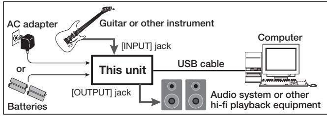
NOTE
- If you monitor the audio signal during recording via the audio output of the computer, there will be an audible delay. Be sure to use the [OUTPUT] jack of this unit to monitor the signal.
- When this unit is operated on USB bus power via the USB cable insufficient power may result in unstable operation or error indications appearing on the display. In such a case, power the device from an AC adapter or batteries.
- Use a high-quality USB cable and keep the connection as short as possible. If USB bus power is supplied to this unit via a USB cable that is more than 3 meters in length, the low voltage warning indication may appear.
HINT
No special steps are necessary for canceling the USB connection. Simply disconnect the USB cable from the computer.
When you connect this unit for the first time to a computer running Windows Vista, a message saying "New Hardware Found" will appear. Before proceeding, wait a while until this message disappears.

Bring up the "Sound" window from the Control Panel and make the input device setting for the computer.
To bring up the "Sound" window, select "Control Panel" from the Start menu and click "Hardware and Sound", then click "Sound".
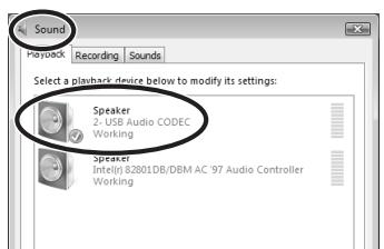
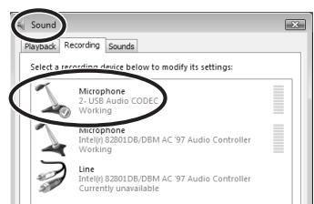
In the "Sound" window, verify that "USB Audio CODEC" is listed under the Play and Record devices and that the device is checked. (To switch between Play and Record, click the tabs at the top of the window.) If the device is not checked, right-click on the icon for the device and click "Set as Default Device" so that a check mark appears.

Start Cubase LE 4. Then access the "Devices" menu, select "Device Setup..." and click "VST Audio System".
To start Cubase LE 4, double-click the Cubase LE 4 shortcut icon that was created on the desktop. After startup, select "ZOOM ASIO Driver" as the ASIO driver in the right section of the Device Setup window. When you change the ASIO driver selection, a confirmation message appears. Click the "Switch" button.
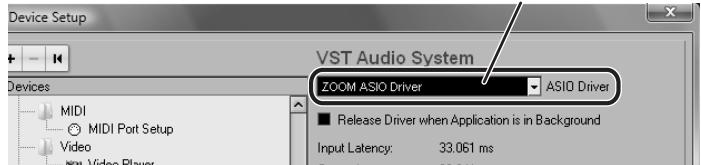
ASIO driver
The device indication in the left section of the window now shows "ZOOM ASIO Driver" as the ASIO driver.
Click on this indication to select it, and then click the "Control Panel" button in the right section of the Device Setup window.
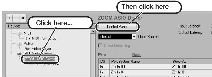
The window that appears lets you set the latency and sampling frequency for the ASIO driver. The latency should be set to a value that is as low as possible without causing sound dropouts during recording and playback.
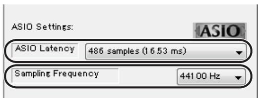
When the setting is complete, click the OK buttons in the respective windows to return to the startup condition of Cubase LE 4.

Continued overleaf
Cubase LE 4 installation
Connections and preparation
Use Cubase LE 4 to record
MacOS X
To connect this unit to a computer running MacOS X and enable audio input/output, proceed as follows.

Insert the supplied "Cubase LE 4" DVD-ROM into the DVD drive of the Macintosh.
The contents of the DVD-ROM appear automatically. If nothing happens when you insert the DVD-ROM, double-click the "Cubase LE 4" icon shown on the desktop.

Install Cubase LE 4 on the Macintosh.
When the contents of the DVD-ROM appear, open the "Cubase LE 4 for MacOS X" folder by double-clicking it, and then double-click the "Cubase LE 4.mpkg" file to start the installation process.

Cubase LE 4.mpkg

Connect this unit to the computer using a USB cable.
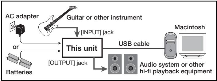
NOTE
- If you monitor the audio signal during recording via the audio output of the computer, there will be an audible delay. Be sure to use the [OUTPUT] jack of this unit to monitor the signal.
- When this unit is operated on USB bus power via the USB cable, insufficient power may result in unstable operation or error indications appearing on the display. In such a case, power the device from an AC adapter or batteries.
- Use a high-quality USB cable and keep the connection as short as possible. If USB bus power is supplied to this unit via a USB cable that is more than 3 meters in length, the low voltage warning indication may appear.
HINT
No special steps are necessary for canceling the USB connection.
Simply disconnect the USB cable from the computer.

Open the "Applications" folder and then the "Utilities" folder, and double-click "Audio MIDI Setup".
The Audio MIDI Setup screen appears. Click "Audio Devices" and check whether "USB Audio CODEC" is selected as default input/ default output.
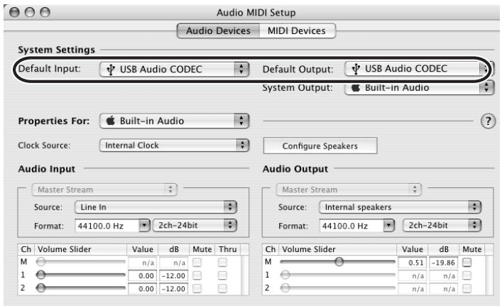
If another device is selected, use the pull-down menu to change the selection to "USB Audio CODEC".
When the setting has been made, close Audio MIDI Setup.

Start Cubase LE 4. Then access the "Devices" menu, select "Device Setup..." and click "VST Audio System".
To start Cubase LE 4, double-click on the Cubase LE 4 icon that was placed in the "Applications" folder during installation.
After startup, be sure to verify that "USB Audio CODEC (2)" is selected as ASIO driver in the right section of the Device Setup window.
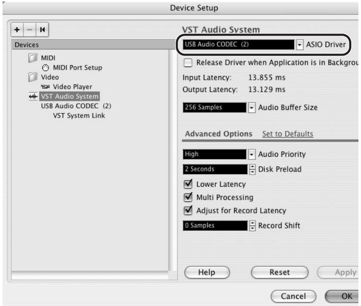
If another item is selected, use the pull-down menu to change the selection to "USB Audio CODEC (2)".
When the setting has been made, click the OK button to close the window.

Continued overleaf
From the "Devices" menu of Cubase LE 4, select "VST Connections" and select the device containing the string "Zm In (Out)" ("USB Audio CODEC" for MacOS X) as input port and output port.
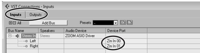
Use the tabs at top (top center for Mac OS X) left to switch between input and output, and verify that "Zm In (Out)" is selected as device port. If another device is selected, click the device port field and change the selection.
7 Access the "File" menu and select "New Project".
The new project window appears. Here you can select a project template.
Make sure that the "Empty" template is selected, and click the OK button.
A window for selecting the project file save location appears.
After specifying a suitable project file save location (such as the desktop), click the OK button (Choose button in MacOS X).
A new project is created, and the project window for controlling most of the Cubase LE 4 operations appears.
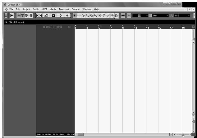
Project window
To create a new audio track, access the "Project" menu and select "Add track". In the submenu that appears, select "Audio".
he Add Track window for specifying the number of audio tracks and the stereo/mono setting appears.
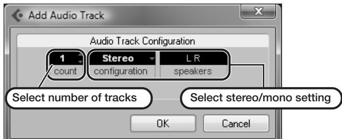
In this example, set the number of tracks to "1" and select stereo, then click the OK button.
A new stereo audio track is added to the project window.
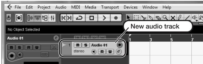
Make the following settings for the newly created audio track.
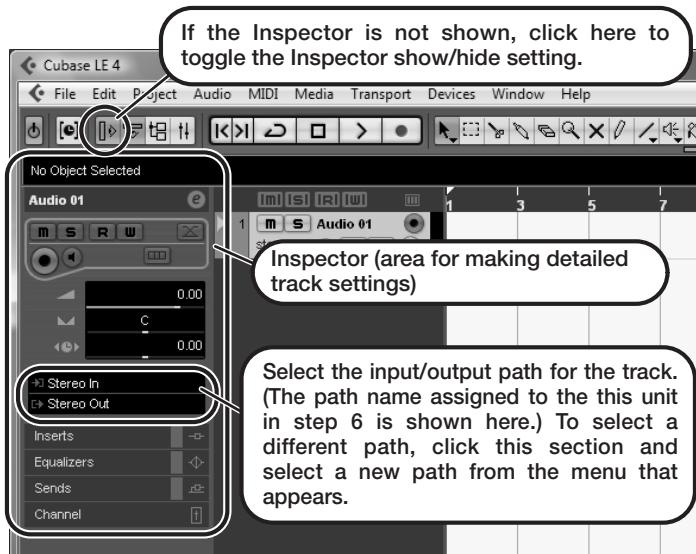
HINT
The Inspector shows information about the currently selected track. If nothing is shown, click on the track to select it.
Connect the guitar or other instrument to the [INPUT] jack of this unit and select the desired patch.
The sound selected here will be recorded on the computer via the [USB] port.
Access the "Devices" menu of Cubase LE 4 and select "Mixer".
The mixer window appears.
This window shows the channel assigned to the created track, and the master channel.
Perform the following steps here.
Mixer window
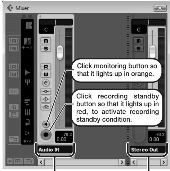
Channel assigned to audio track
Master channel
HINT
When the monitoring button is enabled, the level meter next to the fader shows the input level to the audio track. When the monitoring button is disabled, the meter fader shows the audio track output level.
While playing your instrument, adjust the output level of this unit to achieve a suitable recording level for Cubase LE 4.
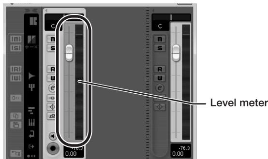
The recording level for Cubase LE 4 can be checked with the level meter for the channel that is assigned to the recording standby track. Set the level as high as possible without causing the meter to reach the end of the scale.
To adjust the level, do not use the fader of Cubase LE 4. Instead change the recording level and gain settings at this unit.
NOTE
- While the monitoring button is enabled, the direct signal input to this unit and the signal routed to the computer and then returned to this unit will be output simultaneously from this unit, causing a flanger-like effect in the sound. To accurately monitor the sound also while adjusting the recording level, temporarily set the output device port for the VST connection (step 6) to "Not Connected".
- The level meter as in the above illustration shows the signal level after processing in this unit. When you pluck a guitar string the meter may register with a slight delay, but this is not a defect.
When the recording level has been adjusted, click the monitoring button to disable it.
The input level is no longer shown on the meter, and the signal returned to this unit via the computer is muted.
In this condition, only the signal before sending to the computer can be monitored via the [OUTPUT] jack of this unit.
Verify that the transport panel is being shown.
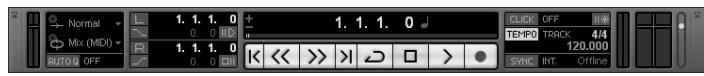
If the transport panel is not shown, access the "Transport" menu and select "Transport Panel".
To start recording, click the Record button in the transport panel.
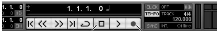
Stop button
Record button
Recording starts.
As you play your instrument, the waveform appears in real time in the project window.
To stop recording, click the Stop button in the transport panel.

Check the recorded content.
To play the recording, perform the following steps.
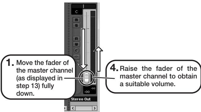
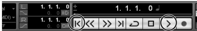
Go to beginning of project
Play button
-
Use the button in the transport panel to move to the beginning of the project.
-
Click the Play button in the transport panel to start playback.
HINT
If no sound is heard when you click the Play button after recording, check the VST connection settings (step 6) once more.
NOTE
To continue using Cubase LE 4, a process called activation (license authentication and product registration) is necessary. When you start Cubase LE 4, a screen offering to register the product will appear. Select "Register Now". A web site for registration will open in your Internet browser. Follow the instructions on that page to register and activate the product.
For optimum enjoyment
While using Cubase LE 4, other applications may slow down drastically or a message such as "Cannot synchronize with USB audio interface" may appear. If this happens frequently, consider taking the following steps to optimize the operation conditions for Cubase LE 4.
(1) Shut down other applications besides Cubase LE 4. In particular, check for resident software and other utilities.
(2) Reduce plug-ins (effects, instruments) used by Cubase LE 4.
When there is a high number of plug-ins, the computer's processing power may not be able to keep up. Reducing the number of tracks for simultaneous playback can also be helpful.
(3) Power the unit from an AC adapter.
When a device designed to use USB power is powered via the USB port, the current supply may sometimes fluctuate, leading to problems. See if using an AC adapter improves operation.
If applications still run very slowly or the computer itself does not function properly, disconnect this unit from the computer and shut down Cubase LE 4. Then reconnect the USB cable and start Cubase LE 4 again.
- BASS EFFECTS CONSOLE
- B9.1ut
- Operation Manual
- 200m
- Safety Precautions / Usage Precautions
- SAFETY PRECAUTIONS
- Power requirements
- Environment
- Handling
- Connecting cables and input and output jacks
- Alterations
- Volume
- Usage Precautions
- Electrical interference
- Cleaning
- Please keep this manual in a convenient place for future reference.
- Contents
- Features
- - Latest technology for top performance
- Ready-to-use patches
- Tube powered Accelerator
- - Versatile array of effects
- - Two selectable operation modes (manual mode/play mode)
- XLR connectors for direct output
- Z-Pedal senses not only vertical but even horizontal movement
- - Programmable function foot switches
- Terms Used in This Manual
- ■ Effect module
- ■ Effect type
- ■ Effect parameter
- Patch
- Bank and group
- ■ Modes
- - Manual mode
- - Play mode
- - Edit mode
- - Store mode
- - Bypass/mute mode
- Controls and Functions
- B9.1ut Top Panel
- B9.1ut Rear Panel
- Control section
- Accelerator section
- Pre-amp section
- Getting Connected
- Connection example (1)
- ■ Connection example (2) (Using the B9.1ut as a DI)
- GROUND switch
- ■ Connection example (3) (External effect connection)
- EXT LOOP GAIN switch
- Power-On
- HINT
- NOTE
- Switching modules on and off with your foot (manual mode)
- Use the PATCH/BANK [] / [] foot switches to select a patch.
- [Identical display items in manual mode and play mode]
- Press the foot switch for the module to be switched on and off.
- Pre-amp operation
- Selecting patches (play mode)
- Editing a patch (edit mode)
- Press the effect module key for the module to edit.
- Use the [TYPE] knob and parameter knobs 1 - 4 to make adjustments.
- Storing a patch (store mode)
- In play mode, manual mode, or edit mode, press the [STORE/SWAP] key.
- The indication "PATCH" appears in the top right of the display and the indication "STORE?" in the bottom left.
- Select the store target bank/patch number.
- Press the [STORE/SWAP] key once more.
- Switching Modules On and Off (Manual Mode)
- Panel display
- Group name/Bank number/Patch number
- Selecting patches
- Make sure that the [MANUAL] key is lit.
- Use the PATCH/BANK [] / [] foot switches to select a patch.
- Turning a module on and off
- Adjusting the sound
- Using the Accelerator
- [TUBE] control
- [SOLID STATE] control
- - Tube control unity gain setting
- Solid state unity gain setting
- Selecting Patches for Playing (Play Mode)
- Make sure that the [MANUAL] key is out.
- "E" symbol
- Press a foot switch 1 - 4 which corresponds to the patch you want.
- To return to manual mode, press the [MANUAL] key.
- To switch to a patch in another bank, use the PATCH/BANK [▼]/[▲] foot switches to change the bank and then use foot switches 1 - 4 to select the patch.
- Using the Tuner (Bypass/Mute Mode)
- Using the chromatictuner
- In manual mode, play mode, or edit mode, press and hold the [BYPASS/TUNER] key.
- - To switch to the bypass mode
- - To switch to the mute mode
- Play the open string to tune.
- Tune the string of your instrument while checking the note and pitch indication.
- To change the reference pitch of the tuner, turn parameter knob 1.
- When tuning is completed, press the [BYPASS/TUNER] key.
- Using the bass tuner
- Switch the B9.1ut to the bypass or mute mode as described in step 1 of "Using the chromatic tuner".
- Turn the [TYPE] knob to select "BASS" as tuner type.
- If necessary, turn parameter knob 1 to change the reference pitch of the tuner.
- Play the open string of the indicated number and adjust the pitch.
- Changing the Sound of a Patch (Edit Mode)
- Patch configuration
- Basic edit mode steps
- Select the patch to edit.
- In play mode or manual mode, press the effect module key (see illustration on next page) to select the module on which to operate.
- To switch the selected module between on and off, press the same module key once more.
- To edit the selected module, proceed as follows.
- [When a module other than PRE-AMP/EQ is selected]
- [When PRE-AMP module is selected]
- [When EQ module is selected]
- Repeat steps 2 - 4 to edit other modules in the same way.
- When editing is finished, press the [EXIT] key.
- Changing a patch name
- Storing Patches and Banks (Store Mode)
- Storing/swapping patches
- Press the [STORE/SWAP] key once more.
- Storing/swapping banks
- Turn parameter knob 1 to bring up the indication "STORE?" or "SWAP?" on the display.
- Returning patches to factory default condition
- Turn power to the B9.1ut on while holding down the [STORE/SWAP] key.
- Press the [STORE/SWAP] key once more.
- Using the Expression Pedal
- About the expression pedal
- Assigning control targets to the expression pedal
- To use the expression pedal for switching the module on and off, turn parameter knob 4 and select "Switch:Enable".
- Repeat steps 3 - 6 to set the other control targets for the vertical direction in the same way.
- To assign control targets for the horizontal direction, turn the [TYPE] knob to select one of the four horizontal direction control targets (PH1 to PH4).
- Repeat steps 4 - 5 to set the parameter and minimum and maximum values for the control target.
- Repeat steps 8 - 9 to set the other control targets for the horizontal direction in the same way.
- When all settings for expression pedal have been made, press the [EXIT] key.
- Using the expression pedal while switching functions
- Adjusting the expression pedal
- Hold down the [PEDAL] key while turning on power to the unit.
- With the expression pedal fully raised, press the [STORE/SWAP] key.
- Using an external expression pedal
- Adjusting the expression pedal torque
- Adjusting horizontal torque for expression pedal
- Adjusting vertical torque for expression pedal
- Using the Foot Switches
- Making settings for function foot switches
- In manual mode or play mode, select the patch.
- Press the [FOOT SW] key.
- Use the parameter knobs 1 - 3 to select the function for function foot switches 1 - 3.
- - BypassOnOff, Mute OnOff
- - ManualMode
- BPM TAP
- Delay Tap
- Hold Delay
- Delay Mute
- Hold Synth
- TunerDsply
- P-H Disable
- After selecting a function to assign to the function foot switch, press the [EXIT] key.
- Assigning modules to foot switches 1 - 4
- Press the [FOOT SW] key twice.
- Use the parameter knobs 1-4 to select the function for foot switches 1-4.
- - Foot switch 1
- - Foot switch 2
- - Foot switch 3
- Specifying the tempo for a patch
- Press the [TOTAL/FUNCTION] effect module key.
- Turn parameter knob 3 to set the tempo.
- To synchronize a parameter to the specified tempo, select the effect type and effect parameter to synchronize, and select the note symbol as the setting value for the parameter.
- Select a parameter value by selecting a note symbol.
- When the tempo and parameter setting is complete, press the [EXIT] key.
- Using the Effect Loop
- Connect the external effect to the EXT LOOP SEND/RETURN jacks.
- Select the patch in manual mode or play mode.
- Press the [EXT LOOP] effect module key to activate edit mode.
- EXT LOOP
- Use parameter knob 1 to adjust the level of the signal sent from the B9.1ut to the external effect (send level).
- Use parameter knob 2 to adjust the level of the signal sent from the external effect to the B9.1ut (return level).
- MIDI Usage Examples
- What you can do with MIDI
- - Send and receive patch switching information via MIDI
- - Send and receive pedal/switch/key operation information via MIDI
- Exchange patch data between two B9.1ut units via MIDI
- Selecting the MIDI channel
- In manual mode or play mode, press the [SYSTEM] key.
- Turn the [TYPE] knob to select the "MIDI Rx Ch" (MIDI receive channel) parameter.
- Turn parameter knob 1 to select the MIDI channel (1 - 16) on which the B9.1ut will receive MIDI messages.
- Sending and receiving patch switching information via MIDI (program change)
- DIRECT
- Press the [STORE/SWAP] key to save the changes.
- To send and receive program change (+ bank select) messages, connect the B9.1ut and the other MIDI device as follows.
- Using mapping mode
- Turn the [TYPE] knob to bring up the "MIDI PCMODE" (program change mode) parameter.
- Turn parameter knob 1 to bring up the indication "Mapping".
- Turn the [TYPE] knob to bring up the "PC MAP" (program change map) parameter.
- Assign control change numbers to other operations in the same way.
- When the setting is complete, press the [EXIT] key to cancel the SYSTEM menu.
- Press the [STORE/SWAP] key to save the changes.
- To send and receive control change messages, connect the B9.1ut and the other MIDI device as follows.
- Example for sending control change messages
- - When the built-in/external expression pedal is operated
- - When module on/off switching is performed
- - When bypass/mute on/off switching is performed
- Example for receiving control change messages
- - When control change for built-in/ external expression pedal is received
- - When control change for module on/off is received
- - When control change for bypass/mute on/off is received
- Sending pedal synth playing information via MIDI (note on/note off)
- Turn the [TYPE] knob to bring up the "NOTE ON Tx" (send note on/ note off) parameter on the display.
- NOTE ON Tx=ON
- Turn parameter knob 1 to select "ON" or "OFF".
- TG
- HD
- When the setting is complete, press the [EXIT] key to cancel the SYSTEM menu.
- Sending and receiving B9.1ut patch data via MIDI
- Connect the MIDI OUT connector on the source B9.1ut to the MIDI IN connector on the target B9.1ut
- using a MIDI cable.
- Target B9.1ut
- Set the B9.1ut to manual mode or play mode.
- Source B9.1ut
- Press the [STORE/SWAP] key.
- PatchDataDumpRx Receive Patch...
- Other Functions
- Using the ARRM function
- Press the [TOTAL/FUNCTION] effect module key to switch to edit mode, and then turn the [TYPE] knob to bring up the indication "ARRM" on the display.
- Turn parameter knob 1 to select the control target parameter.
- To set the adjustment range for the parameter to be controlled, use parameter knob 2 (minimum value) and parameter knob 3 (maximum value).
- When the control target and parameter range have been set, turn the [TYPE] knob clockwise to bring up the following display.
- Turn parameter knob 1 to select the control waveform type.
- Turn parameter knob 2 to select the control waveform cycle.
- When the ARRM setting is complete, press the [EXIT] key.
- Using the sound-on-sound function
- In manual mode or play mode, press the [DELAY] key.
- Turn the [TYPE] knob to select the effect type "SOS" (sound-on-sound).
- - Function foot switch 2
- - Function foot switch 3
- Turn parameter knob 1 to set the recording duration.
- Mn
- Note symbol
- Turn parameter knob 2 to specify the effect sound mixing ratio.
- When the sound-on-sound settings are complete, press the [EXIT] key.
- While playing your bass, press function foot switch 3 to start recording.
- "Mn" is selected
- Note symbol is selected
- To record another layer, press function foot switch 3 again during loop playback.
- To stop loop playback, press function foot switch 2.
- To clear the recorded contents, hold down function foot switch 2.
- Using the pedal synth function
- In manual mode or play mode, press the [PRE-AMP] key.
- Turn the [TYPE] knob to select the effect type "PedalSyn" (pedal synth).
- Turn parameter knob 3 to select the pedal synth scale and the sound generation method.
- TG
- To specify the keynote (the sound produced by foot switch 1), turn parameter knob 2.
- To change the pedal synth sound, turn parameter knob 3. To adjust the balance between original sound and effect sound, turn parameter knob 4.
- When the pedal synth settings are complete, press the [EXIT] key.
- To play the pedal synth sounds, press the foot switches except for function foot switch 2.
- To return all front panel foot switches to normal operation, press function foot switch 2.
- Using the B9.1ut as audio interface for a computer
- Compatible operating system
- Quantization 16-bit
- Sampling frequencies 32 kHz / 44.1 kHz / 48 kHz
- Muting the direct output when using a USB connection
- Changing the default reference pitch of the tuner
- Use as a direct box
- Checking the B9.1ut version
- Turn the [TYPE] knob to bring up
- the "System Version" indication.
- After checking the system version, press the [EXIT] key.
- Editor/librarian software for the B9.1ut
- Web site of ZOOM CORPORATION
- Linking Effects
- Using the Pickup Select function
- PASSIVE
- ACTIVE
- When the setting is complete, press the [EXIT] key.
- Press the [STORE/SWAP] key to store the new setting.
- Changing the insert position of the pre-amp section and WAH/EFX1 module
- Changing the insert position of the WAH/EFX1 module
- In manual mode, play mode, or edit mode, press the [WAH/EFX1] key.
- Turn the [TYPE] knob and select an effect type other than Octave, Tremolo, Defret, Splitter, or X-Vibe.
- Turn parameter knob 1 to select "Befr" (before pre-amp section) or "Aftr" (after pre-amp section).
- WAH:Autoliah Position Aftr
- When the setting is complete, press the [EXIT] key.
- Changing the insert position of the pre-amp section
- In manual mode, play mode, or edit mode, press the [PRE-AMP] key.
- Turn the [TYPE] knob and select an effect type other than a bass synth effect.
- Turn parameter knob 3 to select "Pre" (before MOD/EFX2 module) or "Post" (after DELAY module).
- Effect Types and Parameters
- How to read the parameter table
- Tempo sync
- Expression pedal
- Delay tap/hold delay/delay mute/hold synth
- DigiFuzz
- EQ (Equalizer) module
- Chorus
- Z-Talking
- ReverseDelay
- REVERB module
- Hall
- Room
- Spring
- Arena
- TiledRoom
- ModernSpring
- Troubleshooting
- No sound or very low volume
- Sound is distorted
- Foot switches do not operate properly
- ■ Noise is noticeable
- Hum noise is heard (when using BALANCED OUT connectors)
- ■ Effects do not work
- Cannot send or receive MIDI messages
- ■ Expression pedal does not operate properly.
- On/off switching with expression pedal does not work properly
- B9.1ut Specifications
- B9.1ut patch/bank number + program number assignment table
- The FCC regulation warning (for U.S.A.)
- Disposal of Old Electrical & Electronic Equipment (Applicable in European countries with separate collection systems)
- ZOOM CORPORATION
- B9.1ut Patch List
- Cubase LE 4 installation
- Connections and preparation
- Use Cubase LE 4 to record
- Windows Vista / XP
- Connect this unit to the computer using a USB cable.
- MacOS X
- Access the "File" menu and select "New Project".
- Make sure that the "Empty" template is selected, and click the OK button.
- After specifying a suitable project file save location (such as the desktop), click the OK button (Choose button in MacOS X).
- To create a new audio track, access the "Project" menu and select "Add track". In the submenu that appears, select "Audio".
- Connect the guitar or other instrument to the [INPUT] jack of this unit and select the desired patch.
- Access the "Devices" menu of Cubase LE 4 and select "Mixer".
- Mixer window
- While playing your instrument, adjust the output level of this unit to achieve a suitable recording level for Cubase LE 4.
- When the recording level has been adjusted, click the monitoring button to disable it.
- Verify that the transport panel is being shown.
- To start recording, click the Record button in the transport panel.
- Check the recorded content.
- For optimum enjoyment
Brand : ZOOM
Model : B91UT
Category : Audio Effects