
AVR 347 - AV receiver HARMAN KARDON - Free user manual and instructions
Find the device manual for free AVR 347 HARMAN KARDON in PDF.

| Product Type | Audio-Video Receiver |
| Brand | Harman Kardon |
| Model | AVR 347 |
| Dimensions (W x H x D) | 440 x 165 x 380 mm |
| Weight | 12 kg |
| Power Supply | 220-240 V, 50/60 Hz |
| Power Consumption | 600 W |
| Number of Channels | 7.1 channels |
| Supported Audio Formats | Dolby TrueHD, DTS-HD Master Audio, Dolby Digital Plus, DTS-HD High Resolution |
| HDMI Inputs | 3 HDMI 1.3a inputs |
| HDMI Outputs | 1 HDMI output with on-screen display |
| Composite Video Output | 1 input, 1 output |
| Analog Audio Inputs | 6 stereo RCA inputs, 1 phono input |
| Analog Audio Outputs | 7.1 pre-out outputs, headphone output |
| Digital Inputs | 2 optical inputs, 2 coaxial inputs |
| Radio Tuner | FM/AM with 30 presets |
| Main Features | 7-channel amplification, EzSet/EQ automatic calibration, multiple surround modes |
| Care and Cleaning | Wipe with a soft, dry cloth. Do not use abrasive products. |
| Safety | Do not expose to moisture. Disconnect during storms. Use a suitable outlet. |
| Spare Parts and Repairability | Contact Harman Kardon after-sales service for parts. |
| General Information | This Class B digital device complies with Canadian ICES-003. |
Frequently Asked Questions - AVR 347 HARMAN KARDON
User questions about AVR 347 HARMAN KARDON
0 question about this device. Answer the ones you know or ask your own.
Ask a new question about this device
Download the instructions for your AV receiver in PDF format for free! Find your manual AVR 347 - HARMAN KARDON and take your electronic device back in hand. On this page are published all the documents necessary for the use of your device. AVR 347 by HARMAN KARDON.
USER MANUAL AVR 347 HARMAN KARDON
Designed to Entertain.
AVR 347
AUDIO/VIDEO RECEIVER OWNER'S MANUAL


-
Read Instructions. All the safety and operating instructions should be read before the product is operated.
-
Retain Instructions. The safety and operating instructions should be retained for future reference.
-
Heed Warnings. All warnings on the product and in the operating instructions should be adhered to.
-
Follow Instructions. All operating and use instructions should be followed.
-
Cleaning. Unplug this product from the wall outlet before cleaning. Do not use liquid cleaners or aerosol cleaners. Use a damp cloth for cleaning.
-
Attachments. Do not use attachments not recommended by the product manufacturer, as they may cause hazards.
-
Water and Moisture. Do not use this product near water - for example, near a bathtub, wash bowl, kitchen sink or laundry tub; in a wet basement; near a swimming pool; or the like.
-
Accessories. Do not place this product on an unstable cart, stand, tripod, bracket or table. The product may fall, causing serious injury to a child or adult, and serious damage to the product. Use only with a cart, stand, tripod, bracket or table recommended by the manufacturer, or sold with the product. Any mounting of the product should follow the manufacturer's instructions, and should use a mounting accessory recommended by the manufacturer.
-
A Product and Cart Combination Should Be Moved With Care. Quick stops, excessive force and uneven surfaces may cause the product and cart combination to overturn.

-
Ventilation. Slots and openings in the cabinet are provided for ventilation and to ensure reliable operation of the product and to protect it from overheating, and these openings must not be blocked or covered. The openings should never be blocked by placing the product on a bed, sofa, rug or other similar surface. This product should not be placed in a built-in installation, such as a bookcase or rack, unless proper ventilation is provided or the manufacturer's instructions have been adhered to.
-
Power Sources. This product should be operated only from the type of power source indicated on the marking label. If you are not sure of the type of power supply to your
home, consult your product dealer or local power company. For products intended to operate from battery power, or other sources, refer to the operating instructions.
12. Polarization. This product may be equipped with a polarized alternating-current-line plug (a plug having one blade wider than the other). This plug will fit into the power outlet only one way. This is a safety feature. If you are unable to insert the plug fully into the outlet, try reversing the plug. If the plug should still fail to fit, contact your electrician to replace your obsolete outlet. Do not defeat the safety purpose of the polarized plug.
13. Power-Cord Protection. Power-supply cords should be routed so that they are not likely to be walked on or pinched by items placed upon or against them, paying particular attention to cords at plugs, convenience receptacles, and the point where they exit from the product.
14. Nonuse Periods. The power cord of the product should be unplugged from the outlet when left unused for long periods of time.
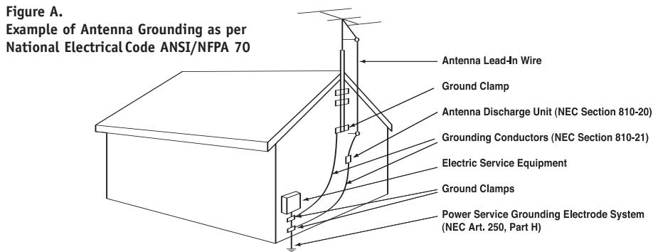
15. Outdoor Antenna Grounding. If an outside antenna or cable system is connected to the product, be sure the antenna or cable system is grounded so as to provide some protection against voltage surges and built-up static charges. Article 810 of the National Electrical Code, ANSI/NFPA 70, provides information with regard to proper grounding of the mast and supporting structure, grounding of the lead-in wire to an antenna discharge unit, size of grounding conductors, location of antenna-discharge unit, connection to grounding electrodes, and requirements for the grounding electrode. See Figure A.
16. Lightning. For added protection for this product during a lightning storm, or when it is left unattended and unused for long periods of time, unplug it from the wall outlet and disconnect the antenna or cable system. This will prevent damage to the product due to lightning and power-line surges.
17. Power Lines. An outside antenna system should not be located in the vicinity of overhead power lines or other electric light or power circuits, or where it can fall into such power lines or circuits. When installing an outside antenna system, extreme care should be taken to keep from touching such power lines or circuits, as contact with them might be fatal.
- Overloading. Do not overload wall outlets, extension cords, or integral convenience receptacles, as this can result in a risk of fire or electric shock.
- Object and Liquid Entry. Never push objects of any kind into this product through openings, as they may touch dangerous voltage points or short-out parts that could result in a fire or electric shock. Never spill liquid of any kind on the product.
- Servicing. Do not attempt to service this product yourself, as opening or removing covers may expose you to dangerous voltage or other hazards. Refer all servicing to qualified service personnel.
- Damage Requiring Service. Unplug this product from the wall outlet and refer servicing to qualified service personnel under the following conditions:
a. The power-supply cord or the plug has been damaged; or b. Objects have fallen onto, or liquid has been spilled into, the product; or
c. The product has been exposed to rain or water, or
d. The product does not operate normally when following the operating instructions. Adjust only those controls that are covered by the operating instructions, as an improper adjustment of other controls may result in damage and will often require extensive work by a qualified technician to restore the product to its normal operation; or
e. The product has been dropped or damaged in any way; or f. The product exhibits a distinct change in performance; this indicates a need for service. - Replacement Parts. When replacement parts are required, be sure the service technician has used replacement parts specified by the manufacturer or that have the same characteristics as the original part. Unauthorized substitutions may result in fire, electric shock or other hazards.
- Safety Check. Upon completion of any service or repairs to this product, ask the service technician to perform safety checks to determine that the product is in proper operating condition.
- Wall or Ceiling Mounting. The product should be mounted to a wall or ceiling only as recommended by the manufacturer.
- Heat. The product should be situated away from heat sources such as radiators, heat registers, stoves or other products (including amplifiers) that produce heat.
Important Safety Information
Verify Line Voltage Before Use
Your AVR 347 has been designed for use with 120-volt AC current. Connection to a line voltage other than that for which it is intended can create a safety and fire hazard and may damage the unit.
If you have any questions about the voltage requirements for your specific model, or about the line voltage in your area, contact your selling dealer before plugging the unit into a wall outlet.
Do Not Use Extension Cords
To avoid safety hazards, use only the power cord attached to your unit. We do not recommend that extension cords be used with this product. As with all electrical devices, do not run power cords under rugs or carpets or place heavy objects on them. Damaged power cords should be replaced immediately by an authorized service center with a cord meeting factory specifications.
Handle the AC Power Cord Gently
When disconnecting the power cord from an AC outlet, always pull the plug; never pull the cord. If you do not intend to use the unit for any considerable length of time, disconnect the plug from the AC outlet.
Do Not Open the Cabinet
There are no user-serviceable components inside this product. Opening the cabinet may present a shock hazard, and any modification to the product will void your guarantee. If water or any metal object such as a paper clip, wire or staple accidentally falls inside the unit, disconnect it from the AC power source immediately, and consult an authorized service center.
CATV or Antenna Grounding
If an outside antenna or cable system is connected to this product, be certain that it is grounded so as to provide some protection against voltage surges and static charges. Section 810 of the National Electrical Code, ANSI/NFPA No. 70-1984, provides information with respect to proper grounding of the mast and supporting structure, grounding of the lead-in wire to an antenna discharge unit, size of grounding conductors, location of antenna discharge unit, connection to grounding electrodes and requirements of the grounding electrode.
NOTE TO CATV SYSTEM INSTALLER: This reminder is provided to call the CATV (cable TV) system installer's attention to article 820-40 of the NEC, which provides guidelines for proper grounding and, in particular, specifies that the cable ground shall be connected to the grounding system of the building, as close to the point of cable entry as possible.
Installation Location
- To ensure proper operation and to avoid the potential for safety hazards, place the unit on a firm and level surface. When placing the unit on a shelf, be certain that the shelf and any mounting hardware can support the weight of the product.
- Make certain that proper space is provided both above and below the unit for ventilation. If this product will be installed in a cabinet or other enclosed area, make certain that there is sufficient air movement within the cabinet. Under some circumstances, a fan may be required.
- Do not place the unit directly on a carpeted surface.
- Avoid installation in extremely hot or cold locations, or in an area that is exposed to direct sunlight or heating equipment.
- Avoid moist or humid locations.
- Do not obstruct the ventilation slots on the top of the unit, or place objects directly over them.
- Due to the weight of the AVR 347 and the heat generated by the amplifiers, there is the remote possibility that the rubber padding on the bottom of the
unit's feet may leave marks on certain wood or veneer materials. Use caution when placing the unit on soft woods or other materials that may be damaged by heat or heavy objects. Some surface finishes may be particularly sensitive to absorbing such marks, due to a variety of factors beyond Harman Kardon's control, including the nature of the finish, cleaning materials used, and normal heat and vibration caused by the use of the product, or other factors. We recommend that caution be exercised in choosing an installation location for the component and in normal maintenance practices, as your warranty will not cover this type of damage to furniture.
Cleaning
When the unit gets dirty, wipe it with a clean, soft, dry cloth. If necessary, and only after unplugging the AC power cord, wipe it with a soft cloth dampened with mild soapy water, then a fresh cloth with clean water. Wipe it dry immediately with a dry cloth. NEVER use benzene, aerosol cleaners, thinner, alcohol or any other volatile cleaning agent. Do not use abrasive cleaners, as they may damage the finish of metal parts. Avoid spraying insecticide near the unit.
Moving the Unit
Before moving the unit, be certain to disconnect any interconnection cords with other components, and make certain that you disconnect the unit from the AC outlet.
Important Information for the User
This equipment has been tested and found to comply with the limits for a Class-B digital device, pursuant to Part 15 of the FCC Rules. The limits are designed to provide reasonable protection against harmful interference in a residential installation. This equipment generates, uses and can radiate radio-frequency energy and, if not installed and used in accordance with the instructions, may cause harmful interference to radio communication. However, there is no guarantee that harmful interference will not occur in a particular installation. If this equipment does cause harmful interference to radio or television reception, which can be determined by turning the equipment off and on, the user is encouraged to try to correct the interference by one or more of the following measures:
- Reorient or relocate the receiving antenna.
- Increase the separation between the equipment and receiver.
- Connect the equipment into an outlet on a circuit different from that to which the receiver is connected.
- Consult the dealer or an experienced radio/TV technician for help.
This device complies with Part 15 of the FCC Rules. Operation is subject to the following two conditions: (1) this device may not cause harmful interference, and (2) this device must accept interference received, including interference that may cause undesired operation.
NOTE: Changes or modifications may cause this unit to fail to comply with Part 15 of the FCC Rules and may void the user's authority to operate the equipment.
Unpacking
The carton and shipping materials used to protect your new receiver during shipment were specially designed to cushion it from shock and vibration. We suggest that you save the carton and packing materials for use in shipping if you move, or should the unit ever need repair.
To minimize the size of the carton in storage, you may wish to flatten it. This is done by carefully slitting the tape seams on the bottom and collapsing the carton. Other cardboard inserts may be stored in the same manner. Packing materials that cannot be collapsed should be saved along with the carton in a plastic bag.
If you do not wish to save the packaging materials, please note that the carton and other sections of the shipping protection are recyclable. Please respect the environment and discard those materials at a local recycling center.
It is important that you remove the protective plastic film from the front-panel lens. Leaving the film in place will affect the performance of your remote control.
STAPLE INVOICE HERE
2 SAFETY INFORMATION
6 INTRODUCTION
8 FRONT-PANEL CONTROLS
10 REAR-PANEL CONNECTIONS
13 MAIN REMOTE CONTROL FUNCTIONS
16 ZONE II REMOTE CONTROL FUNCTIONS
18 INTRODUCTION TO HOME THEATER
19 CONNECTIONS
19 Speaker Connections
19 Subwoofer
19 Connecting Source Devices to the AVR
Audio Connections
Digital Audio
Analog Audio
Video Connections
Digital Video
Analog Video
Antennas
RS-232 Serial Port
SPEAKER PLACEMENT
INSTALLATION
Step One - Connect the Speakers
Step Two - Connect the Subwoofer
Step Three - Connect the Antennas
Step Four - Connect the Source Components
Step Five - Connect Video Display
Step Six - Plug in AC Power
Step Seven - Insert Batteries in Remote
Step Eight - Program Sources Into the Remote
Step Nine - Remote IR Inputs and Output
Step Ten – Install a Multiroom System
Step Eleven - Turn On the AVR 347
INITIAL SETUP
Using the On-Screen Menu System
Configure the AVR 347 Using EzSet/EQ
What EzSet/EQ Does
Configure Sources
OPERATION
Turning On the AVR 347
Sleep Timer
Volume Control
Mute Function
Tone Controls
Headphones
Source Selection
Audio Input Selection
Video Input Selection
6-/8-Channel Direct Inputs
Using the Tuner
XM Radio Operation
Recording
Using "Bridge"
Selecting a Surround Mode
47 ADVANCED FUNCTIONS
47 Audio Processing and Surround Sound
47 Analog Audio Signals
47 Digital Audio Signals
48 Surround Modes
49 Dolby Surround Settings
49 Default Modes
53 Manual Setup
53 Step One - Determine Speaker Size
53 Step Two - Measure Speaker Distances
53 Step Three - Manual Setup Menu
54 Speaker Size Menu
55 Speaker Crossover Menu
55 Delay Adjust Menu
56 Step Four - Setting Channel Output Levels Manually
57 Video Adjustments
58 Multiroom Operation
58 Installing a Multiroom System
59 Operating the Multiroom System
59 System Settings
60 Dim Function
60 Advanced Remote Control Functions
60 Punch-Through Programming
61 Macros
61 Resetting the Remote
61 Processor Reset
61 Memory
62 TROUBLESHOOTING GUIDE
63 TECHNICAL SPECIFICATIONS
63, 66 Trademark Acknowledgements
64 APPENDIX
WARNING
To prevent fire or shock hazard, do not expose this appliance to rain or moisture.
For Canadian model
This class B digital apparatus complies with Canadian ICES-003.
For models having a power cord with a polarized plug: CAUTION: To prevent electric shock, match wide blade of plug to wide slot, fully insert.
Please register your AVR 347 on our Web site at www.harmankardon.com.
Note: You'll need the product's serial number. At the same time, you can choose to be notified about our new products and/or special promotions.
WWW.HARMANKARDON.COM
Thank you for choosing Harman Kardon®!
In the years since Harman Kardon invented the high-fidelity receiver, we have taken to heart the philosophy of bringing the joy of home entertainment to as many people as possible, adding performance and ease-of-use features that enhance the home entertainment experience. In the years since our first single-channel component was introduced, Harman Kardon has offered a number of receiver models, each an improvement upon its predecessors, leading to the AVR 347, a 7.1-channel digital audio/video receiver that offers a wealth of listening and viewing options, all in an elegant package.
AVR 347 7.1-Channel Audio/Video Receiver
Audio Section
- 55 Watts x 7, seven channels driven at full power at 8 ohms, 20Hz - 20kHz, < 0.07% THD (surround modes), 385 watts total
- 70 Watts x 2, two channels driven at full power at 8 ohms, 20Hz - 20kHz, < 0.07% THD (surround off mode), 140 watts total
- High-current capability, ultrawide-bandwidth amplifier design with low negative feedback
- All-discrete amplifier circuitry
- Dual independent power supplies, for front and surround channels
- Quadruple-crossover bass management
- 24-Bit, twin-core Cirrus Logic® CS 49510 DSP processor with 32-bit postprocessor
- 192kHz/24-bit D/A conversion
- Sampling upconversion to 96kHz
To obtain the maximum enjoyment from your new receiver, we urge you to read this manual and refer back to it as you become more familiar with its features and their operation.
If you have any questions about this product, its installation or its operation, please contact your retailer or customer installer, or visit our Web site at www.harmankardon.com.
Surround Modes
- Dolby® Digital EX
- Dolby Pro Logic II and IIx (Movie, Music and Game)
- Dolby Virtual Speaker Version 2 (Reference two- or three-speaker; Wide two-, three-, four- or five-speaker)
- Dolby Headphone Version 2
- DTS® (5.1; DTS Stereo; DTS-ES® 6.1 Discrete and Matrix)
- DTS 96/24™ (DTS Stereo)
- DTS Neo:6® (Cinema 3-, 5- or 6-channel; Music 5- or 6-channel)
- Logic 7^® (Cinema, Music and Enhance - 5.1 and 7.1)
- Hall 1 and Hall 2 (5- or 6-channel)
- Theater (5- or 6-channel)
- 5- or 7-Channel Stereo
- Surround Off (DSP or Analog Bypass)
Audio Inputs
AM/FM/XM*tuner
CD
- Tape
- 6-/8-Channel direct
- Bridge /DMP for iPod** connectivity with audio/video playback
Audio/Video Inputs (With S-Video)
Video 1
Video 2
Video 3
Video 4 (on front panel)
DVD
- Three assignable 100MHz component video inputs
- Simplay HD^TM -verified HDMI^TM 1 and 2 with audio/video processing, 1080p pass-through and repeater for increased cable lengths without signal degradation
- DCDi® by Faroudja video processing
Transcodes composite and S-video to component video
Transcodes 480i video to HDMI format, with upscaling up to 720p
Upgraded graphic text-based on-screen displays
Digital Audio Inputs
Coaxial: three rear-panel/one front-panel
- Optical: three rear-panel/one front-panel
Outputs
7.1-Channel preamp outputs
- Tape (analog audio)
Video 1 (analog audio and video)
- Video monitor (composite, S-video and component)
- Digital audio (one coaxial, one optical)
- Simplay HD-verified HDMI
- Multiroom audio
- Multiroom speaker- and preamp (shared with surround back channels)
- A-BUS® Ready
- Headphone
Ease of Use
- EzSet/EQ™ automated setup (microphone supplied)
- Graphic on-screen display with HDMI, component, composite and S-video
- Two-line dot-matrix front-panel display
Color-coded connections - Programmable 11-device main remote control
- Source input renaming
- A/V Sync Delay
- RS-232 serial port for system upgrades
- Switched accessory power outlet
- Remote infrared (IR) input and output
- Multiroom IR input
- IEC detachable AC power cord for easy installation
SimplPlay The AVR 347 is Simplay HD-verified for compatibility via the HDMI connection with other Simplay HD-verified products.
Supplied Accessories
The following accessory items are supplied with the AVR 347. If any of these items are missing, please contact Harman Kardon customer service at www.harmankardon.com.
- System and Zone II remote controls
- EzSet/EQ microphone
- AM loop antenna
FM wire antenna - Five AAA batteries
- Two covers for front-panel jacks
- AC Power cord
*XM antenna module and subscription to XM service required. Hardware and service sold separately. XM service is not available in Alaska or Hawaii.
**Compatible with all iPod models equipped with a dock connector. Not compatible with iPod shuffle models. Images and videos stored on iPod photo and video models may be viewed.
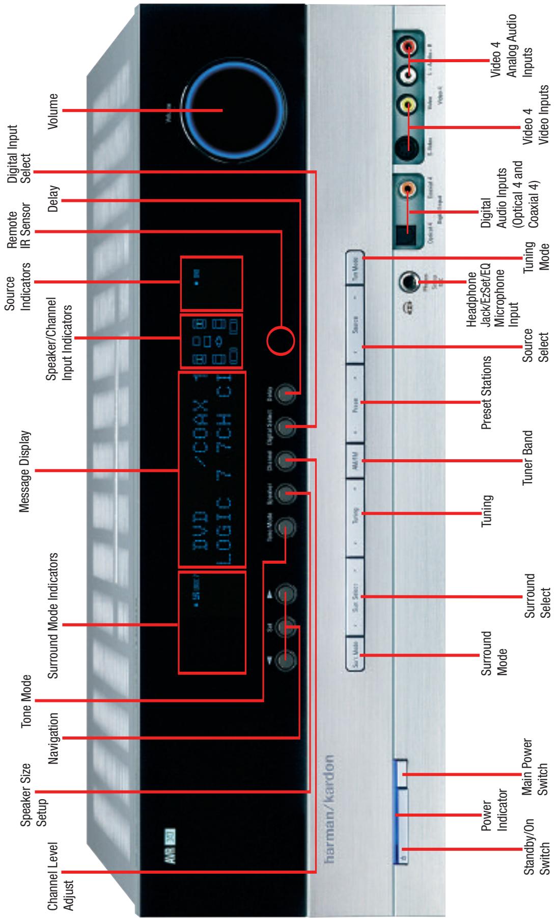
FRONT-PANEL CONTROLS
Main Power Switch: This mechanical switch turns the power supply on or off. It is usually left pressed in (On position), and cannot be turned on using the remote control.
Standby/On Switch: This electrical switch turns the receiver on for playback, or leaves it in Standby mode for quick turn-on using this switch or the remote control.
Power Indicator: This LED has three possible modes. When main power is turned off, the LED is dark and the receiver won't respond to any button presses. When main power is turned on, but before the Standby/On Switch is used, the LED turns amber to indicate that the receiver is in Standby mode and ready to be turned on. When the receiver is turned on, the LED turns blue.
Source Select: Press this button to select a source device, which is a component where a playback signal originates, e.g., DVD, CD, cable TV, satellite or HDTV tuner.
Source Indicators: The name of the current source input lights up. The indicated input changes each time the Source Select button is pressed.
Volume Knob: Turn this knob to raise or lower the volume, which will be shown in decibels (dB) in the Message Display.
Message Display: Various messages appear in this two-line display in response to commands and changes in the incoming signal. When the on-screen display menu system (OSD) is in use, the message OSD ON will appear to remind you to check the video display.
Tuner Band: Press this button to select the tuner as the source, to switch between the AM and FM bands, or to select XM satellite radio.
Tuning: Press either side of this button to tune a radio station or XM channel.
Tuning Mode: This button toggles between manual (one frequency step at a time) and automatic (seeks frequencies with acceptable signal strength) tuning mode. It also toggles between stereo and mono modes when an FM station is tuned.
When XM Radio is in use, pressing this button repeatedly displays the channel name, category, artist and track title in the lower line of the Message Display. For traffic-and-weather channels, this button displays the city, channel name, local weather and local temperature.
Preset Stations: Press this button to select a preset radio station.
Headphone Jack/EzSet/EQ Microphone Input: Plug a 1/4" headphone plug into this jack for private listening.
This jack is also used to connect the supplied microphone before beginning the EzSet/EQ procedure described in the Initial Setup section. To begin EzSet/EQ, plug the supplied microphone into this jack, place the microphone at the listening position, and follow the directions given in the SPEAKER SETUP-AUTO CONFIGURATION on-screen menu.
Surround Mode: Press this button to select a surround sound (e.g., multichannel) mode group. Choose from the Dolby modes, DTS modes, Logic 7 modes, DSP modes or Stereo modes.
Surround Select: After you have selected the desired surround mode group, press this button to select a specific mode.
Surround Mode Indicators: One or more of these icons may light up as you select different surround modes. The Message Display also indicates the surround mode.
Analog Audio, Video and Digital Audio Inputs: Connect a source component that will only be used temporarily, such as a camera or game console, to these jacks. Use only one type of audio and one type of video connection.
Speaker/Channel Input Indicators: The box icons indicate which speaker positions you have configured, and the size (frequency range) of each speaker. When a digital audio input is used, letters will light inside the boxes to indicate which channels are present in the incoming signal.
Navigation: These buttons are used together with the following five buttons to make selections.
Tone Mode: Press this button to access the tone controls (bass and treble). Use the / Navigation Buttons to make your selections.
Speaker: Press this button to configure speaker sizes; that is, the low-frequency-range capability of each speaker.
Channel Level Adjust: Press this button to set the output level for each channel so that all speakers sound equally loud at the listening position.
Digital Input Select: Press this button to select the specific digital audio input (or analog audio input) you used for the current source.
Delay: Press this button to set delay times that compensate for placing the speakers at different distances from the listening position.
Remote IR Sensor: This sensor receives infrared (IR) commands from the remote control. It is important to ensure that it is not blocked. If covering the sensor is unavoidable, such as when the AVR 347 is placed inside a cabinet, you may use an optional Harman Kardon HE 1000, or other infrared receiver, connecting it to the Remote IR Input on the AVR 347's rear panel. Alternatively, connect the Remote IR Output of another compatible component to the AVR 347's Remote IR Input. Point the remote at the other device's remote sensor, and the command will be transmitted to the AVR 347. An external IR "blaster" may also be used, positioned to point at this area.
NOTE: To make it easier to follow the instructions throughout the manual that refer to this illustration, a copy of this page may be downloaded from the Product Support section at www.harmankardon.com.
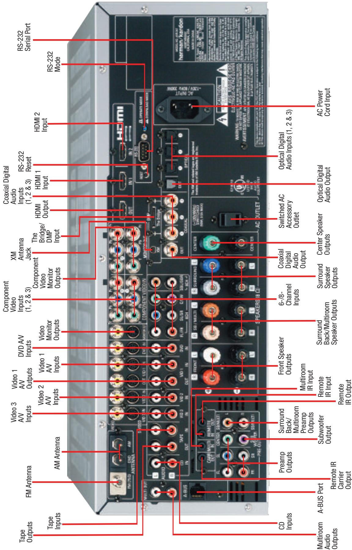
REAR-PANEL CONNECTIONS
AM and FM Antenna Terminals: Connect the included AM and FM antennas to their respective terminals for radio reception.
XM Antenna Jack: Plug in an XM antenna module here. The XM antenna module is purchased separately, and should specify that it is for home use with an XM Ready® product. You will need to subscribe to the XM service, which is available separately, and activate the service for your antenna module. (XM service is not available in Alaska and Hawaii.)
Front, Center and Surround Speaker Outputs: Use two-conductor speaker wire to connect each set of terminals to the correct speaker. Remember to observe the correct polarity (positive and negative connections). Always connect the positive lead to the colored terminal on the receiver and the red terminal on the speaker. Connect the negative lead to the black terminal on both the receiver and the speaker. See the Connections section for more information on connecting your speakers.
Surround Back/Multiroom Speaker Outputs: These speaker outputs may be used either for the surround back channels in a 7.1-channel home theater, or they may be reassigned to a remote room for use with a multiroom system. When these outputs are reassigned for multiroom operation, only a 5.1-channel configuration will be available in the main listening room. Use the on-screen menu system to configure these channels as desired.
As with the other speaker outputs, remember to observe proper polarity by connecting the positive and negative output terminals to the corresponding terminals on each speaker.
Subwoofer Output: If you have a powered subwoofer with a line-level input, connect it to this jack.
Preamp Outputs: Connect these jacks to an external amplifier if more power is desired.
Surround Back/Multiroom Preamp Outputs: These outputs may be used with an external amplifier either to power the surround back channels, or to power the speakers in the remote zone of a multi-channel system. Use the on-screen menu system to configure these channels as desired.
Remote Infrared (IR) Input and Output: When the remote IR receiver on the front panel is blocked, such as when the AVR is placed inside a cabinet, connect an optional IR receiver to the Remote IR Input jack for use with the remote control. The Remote IR Output may be connected to the Remote IR Input of a compatible source device (or other product) to enable remote control through the AVR. This is particularly useful in multiroom applications, when you wish to control the source device from the remote room (when used with the Multiroom IR Input). When several source devices are used, connect them in "daisy chain" fashion.
Multiroom Infrared (IR) Input: Connect a remote IR receiver located in the remote zone of a multiroom system to this jack to control the AVR and any source devices connected to the Remote IR Output from the remote zone.
Remote IR Carrier Output: This output is similar in function to the Remote IR Output, with the difference that this jack outputs the full infrared signal as received by the AVR's IR sensor or the Remote IR Input, while the Remote IR Output jack outputs a "stripped" signal that has no carrier frequency. The full signal may be required by some components with IR inputs. It may also be required when you connect external IR emitters or other devices to the AVR to pass IR signals to other components.
Multiroom Audio Outputs: Connect these jacks to an external amplifier to power the speakers in the remote zone of a multiroom system. When these jacks are used, it is possible to have a full 7.1-channel system in the main listening room at the same time the multiroom system is in use.
A-BUS Port: Use a Category 5/5e cable to connect this port to optional A-BUS equipment for multiroom operation. When the A-BUS system is used, it is possible to have a full 7.1-channel system in the main listening room at the same time the multiroom system is in use.
Video 1, Video 2, Video 3 and DVD Audio/Video Inputs: These jacks may be used to connect your video-capable source components (e.g., VCR, DVD player, cable TV box) to the receiver. Remember to use only one type of video connection for each source. See the Connections section for more information on audio and video connection options for each source component.
Video 1 Audio/Video Outputs: These jacks may be used to connect your VCR or another recorder.
Composite and S-Video Monitor Outputs: If any of your sources use composite or S-video connections, you may need to connect one or both of these monitor outputs to the corresponding inputs on your television or video display in order to view the sources and to view the on-screen displays. If your video display is equipped with component video or HDMI inputs, you may take advantage of the AVR 347's transcoding capability, which transcodes composite and S-video signals to component video and HDMI, allowing for only a single video connection from the AVR to the video display.
HDMI Inputs and Output: HDMI (High-Definition Multimedia Interface) is a newer type of connection for transmitting digital audio and video signals between devices. With the AVR 347's powerful processor, you may connect up to two HDMI-equipped source devices to the HDMI inputs using a single-cable connection, while benefiting from superior digital audio and video performance. However, if your video display is not HDMI-compatible, you will need to connect the device to one of the other source inputs, selecting a coaxial or optical digital audio input and analog video input. See the Connections and Installation sections for more information.
If your video display has an HDMI input, but some of your sources have only analog video outputs, you may still rely on just the HDMI video connection to your display; the AVR 347 will automatically transcode analog video signals up to 720p to the HDMI format. High-resolution analog 1080i or higher signals are not available at the HDMI Output, but 1080i signals received through one of the HDMI Inputs will be passed through directly to the HDMI Output without any video processing.
The AVR 347 is Simplay HD-verified for compatibility via the HDMI connection with other Simplay HD-verified products.
CD and Tape Audio Inputs: These jacks may be used to connect audio-only source components (e.g., CD player, tape deck). Do not connect a turntable to these jacks without a phono preamp.
Tape Outputs: These jacks may be used to connect a CDR or another audio-only recorder.
Coaxial and Optical Digital Audio Inputs: If a source has a compatible digital audio output, and if you are not using an HDMI connection for audio for the device, connect it to one of these jacks for improved audio performance. Use only one type of digital audio connection for each source.
Coaxial and Optical Digital Audio Outputs: If a source is also an audio recorder, you may connect a compatible digital audio output to the recorder's input for improved recording quality.
The Bridge/DMP Input: Connect the optional Harman Kardon to this input for use with your iPod (not included). Make sure the receiver is turned off (in Standby mode) when connecting The Bridge.
6-/8-Channel Inputs: Connect the multichannel analog audio outputs of a DVD-Audio, SACD™, Blu-ray Disc™ or HD-DVD™ player (or any other external decoder) to these jacks to enjoy these proprietary formats.
NOTE: When an HD-DVD or Blu-ray Disc player has an onboard digital decoder, it is not necessary to connect it to the 6-/8-Channel Analog Audio Inputs. Only a digital audio connection (HDMI, coaxial or optical) is needed.
Component Video Inputs: If both a video source (e.g., DVD player or HDTV tuner) and your television or video display have analog component video (Y/Pb/Pr) capability and if you are not using HDMI connections for the device, then you may connect the component video outputs of the source to one of the two component video inputs. Do not make any other video connections to that source.
Component Video Monitor Outputs: If you are using one of the Component Video Inputs and your television or video display is component-video-capable and if you are not connecting the HDMI output to our display, you may connect these jacks to the corresponding inputs on your video display.
NOTES:
- Due to copy-protection restrictions, there is no output at the Component Video Monitor Outputs for copy-protected sources.
-
High-resolution 1080i and 1080p video signals are not available at the HDMI Output, but 1080i signals are passed through, as is, to the Component Video Outputs. If your source output is analog high-resolution video, either use the AVR's Component Video Outputs, lower the output resolution of your source device, or connect your source's component video outputs directly to your video display.
-
Due to the design of some video displays, analog 480p or 720p component video source signals may produce artifacts when used with the AVR's analog video outputs (composite, S-video or component video). If this occurs, try changing the Video Mode setting in the INPUT SETUP menu, or connecting the source device's video output directly to your video display. However, for best results, we recommend you consider upgrading to an HDMI-capable video display.
RS-232 Serial Port: This specialized connector may be used with your personal computer in case Harman Kardon offers a software upgrade for the receiver at some time in the future.
RS-232 Mode: Leave this switch popped out in the Operate position unless the AVR 347 is being upgraded.
RS-232 Reset: This switch is only used during a software upgrade. A standard processor reset is performed by pressing and holding the front-panel Tone button.
Switched AC Accessory Outlet: You may plug the AC power cord of one source device into this outlet, and it will turn on whenever you turn on the receiver. Do not use a source that consumes more than 50 watts of power.
AC Power Cord Input: After you have made all other connections, plug the AC power cord into an unswitched outlet. Plug the female end of the cord into this receptacle, which conveniently allows you to install all wiring ahead of time.
NOTE: To make it easier to follow the instructions throughout the manual that refer to this illustration, a copy of this page may be downloaded from the Product Support section at www.harmankardon.com.
The AVR 347 remote is capable of controlling 11 devices, including the AVR itself and an iPod docked in the optional The Bridge accessory. During the installation process, you may program the codes for each of your source components into the remote. Each time you wish to use the codes for any component, first press the Selector button for that component. This changes the button functions to the appropriate codes for that product.
NOTE: Several of the Input Selectors are shared between two devices. The selector button will light in red when the remote is in the device mode printed on the button, and it will light in green for the device mode printed above the button. To switch between the two device modes, press the selector twice quickly in succession. The selector will remain in the last-selected mode until the next time you press the selector twice quickly.
For example, the first time you press the DVD button, the button will light up in red, indicating that the remote is in DVD mode. If you press another selector, such as the VID3 selector, and then press the DVD button again, the DVD button will remain red, indicating the remote is still in DVD mode. Now press the DVD button twice quickly. At the first press the button will light red, indicating that the remote is in DVD mode. On the second press the button will turn green, indicating that the remote is now in CD mode. If you press a different selector and return to the DVD/CD Selector, you will observe that the remote is still in CD mode.
Each Input Selector has been preprogrammed to control certain types of components, with only the codes specific to each brand and model changing, depending on which product code is programmed. The device types programmed into each selector may not be changed; however you may program the HDMI 1 and 2 selectors with the DVD, Cable/Satellite or VCR/PVR device type.
DVD: Controls DVD players and recorders.
CD: Controls CD players and recorders.
Tape: Controls cassette decks.
Video 1: Controls VCRs, TiVo® and PVRs.
Video 2: Controls cable and satellite television set-top boxes.
Video 3: Controls televisions and other video displays.
Video 4: Controls televisions and other video displays.
HDMI 1 and 2: Each code set controls a source device (VCR/PVR, DVD player or cable/satellite set-top box) connected to one of these two inputs.
XM: Controls the AVR functions for XM Satellite Radio.
The Bridge/DMP: Controls an iPod docked in The Bridge.
Any given button may have different functions, depending on which component is being controlled. Some buttons are labeled with these functions. For example, the Sleep and DSP Surround Buttons are labeled for use as Channel Up/Down Buttons when controlling a television or cable box. See Table A8 in the appendix for listings of the different functions for each type of component.
IR Transmitter Lens: As buttons are pressed on the remote, infrared codes are emitted through this lens. Make sure it is pointing toward the component being operated.
Power On Button: Press this button to turn on the AVR or another device. The Master Power Switch on the AVR 347's front panel must first have been switched on.
Mute Button: Press this button to mute the AVR 347's speaker and headphone outputs temporarily. To end the muting, press this button or adjust the volume. Muting is also canceled when the receiver is turned off.
Program Indicator: This LED lights up or flashes in one of three colors as the remote is programmed with codes.
Power Off Button: Press this button to turn off the AVR 347 or another device.
AVR Selector: Press this button to switch the remote to the codes that operate the receiver.
Input Selectors: Press one of these buttons to select a source device, which is a component where a playback signal originates, e.g., DVD, CD, cable TV, satellite or HDTV tuner, or an iPod docked in the optional The Bridge. This will also turn on the receiver and switch the remote's mode to operate the source device.
XM Radio Button: Press this button to select XM Satellite Radio as the source. You will need to have purchased and activated an XM antenna module, and you will also need to subscribe to the XM Radio service. Visit www.xmradio.com for more information.
AM/FM Button: Press this button to select the tuner as the source, or to switch between the AM, FM and XM Radio bands.
6-/8-Channel Input Selector: Press this button to select the 6-/8-Channel Inputs as the audio source. The receiver will use the video input and remote control codes for the last-selected video source.
Learn Button: The AVR 347 remote is capable of "learning" individual IR codes from the original remote that came with your TV or a device that is connected to any of the source inputs. See the Advanced Functions section for instructions on learning remote codes.
Test Tone: Press this button to activate the test tone for manual output-level calibration.
TV/Video: This button has no effect on the receiver, but is used to switch video inputs on some video source components.
Sleep Button: Press this button to activate the sleep timer, which turns off the receiver after a programmed period of time of up to 90 minutes.
Volume Controls: Press these buttons to raise or lower the volume, which will be shown in decibels (dB) in the Message Display.
DSP Surround: Press this button to select a DSP surround mode (Hall 1, Hall 2, Theater).
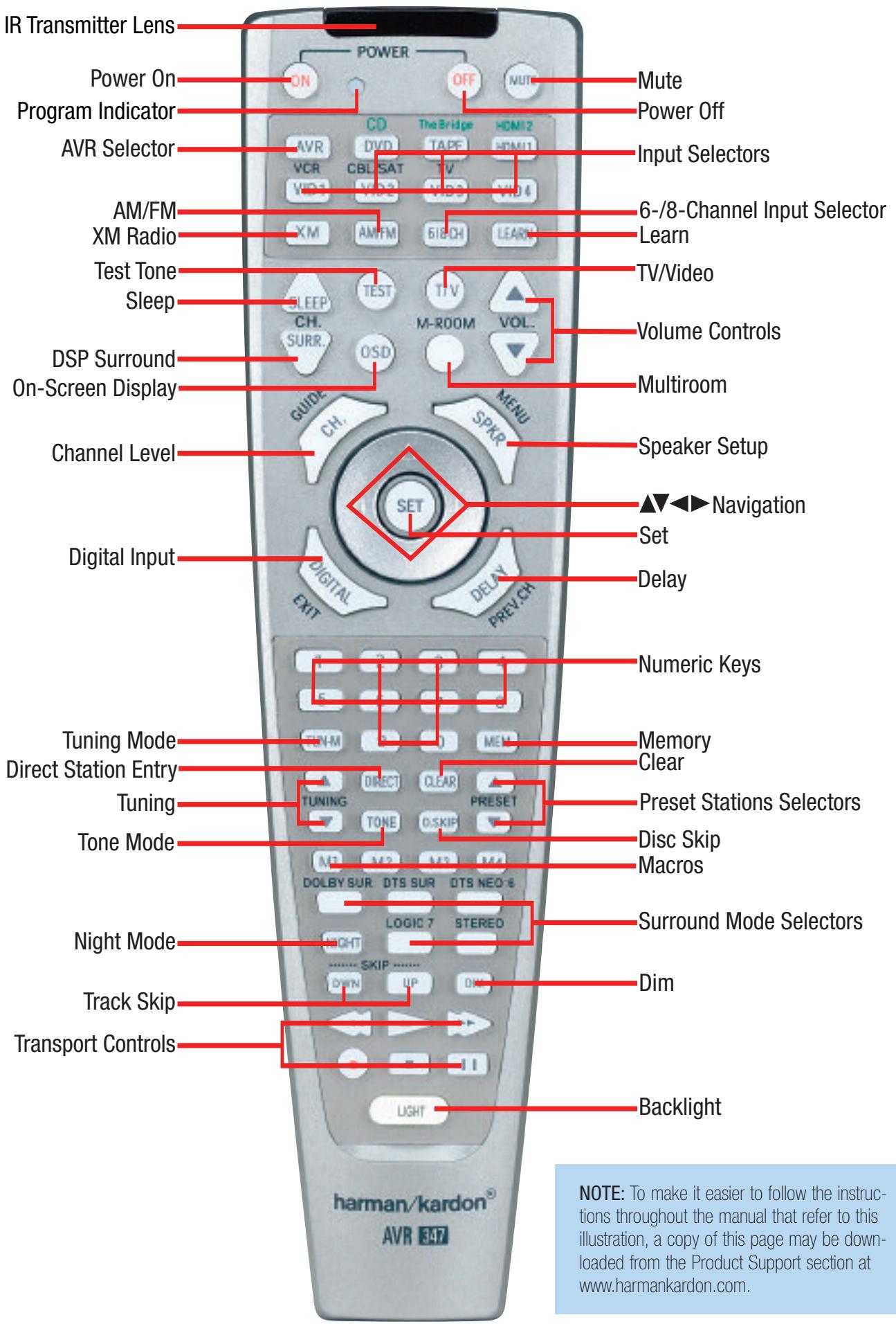
On-Screen Display (OSD): Press this button to activate the on-screen menu system.
Multiroom: Press this button to control the multiroom system. Three settings are available: MULTI ON/OFF, which is used to turn the multiroom system on or off; MULTI LEVEL, which adjusts the volume of the remote zone only; and MULTI INPUT, which is used to select the source input for the remote zone. See Multiroom Operation in the Advanced Functions section for more information on using the AVR 347's multiroom system.
Channel Level: Press this button to adjust the output levels for each channel so that all speakers sound equally loud at the listening position. Usually this is done while playing an audio selection, such as a favorite CD, after you have calibrated the levels using EzSet/EQ, as described in the Initial Setup section.
Speaker Setup: Press this button to configure speaker sizes, that is, the low-frequency capability of each speaker. Usually this is done using the on-screen menu system, as described in the Initial Setup section.
Navigation ( / / / ) and Set Buttons: These buttons are used to make selections within the on-screen menu system, or when accessing the functions of the four buttons surrounding this area of the remote - Channel Level, Speaker Setup, Digital Input or Delay.
Digital Input Select: Press this button to select the specific digital audio input (or analog audio input) you used for the current source.
Delay: Press this button to set delay times that compensate for placing the speakers at different distances from the listening position, or to resolve a "lip sync" issue that may be caused by digital video processing. This may also be done using the on-screen menu system, as described in the Initial Setup section.
Numeric Keys: Use these buttons to enter radio station frequencies or to select station presets. When the AM or FM band is in use, press the Direct button before entering the station frequency.
When listening to XM Radio, you may enter channel numbers without first pressing the Direct Button; however, use the Preset Stations Selectors to access the preset stations. To access another bank of XM presets, press the Set Button repeatedly until PRESET SEARCH appears, then use the / Buttons to select the letter of the desired bank.
Tuning Mode: When listening to AM or FM radio, this button toggles between manual (one frequency step at a time) and automatic (seeks frequencies with acceptable signal strength) tuning mode. It also toggles between stereo and mono modes when an FM station is tuned.
When listening to XM Radio, press the Tuning Mode Button once to view the category name of the current channel. Additional presses will display the artist, song title and channel name.
Memory: After you have tuned a particular radio station, press this button, then the numeric keys, to save that station as a radio preset.
For XM Radio, the procedure for saving a preset is a little different. To save the current channel in one of the 40 available preset locations,
press the Set Button repeatedly until PRESET SEARCH appears. Use the / Buttons to select a letter (A through E) representing one of the five banks of preset memory slots. Then press the Memory Button, followed by a Numeric Key (1 through 8) for the precise preset memory location you wish to save the channel in.
Tuning: Press these buttons to tune a radio station or XM Radio channel. For the AM and FM bands, and depending on whether the tuning mode has been set to manual or automatic, each press will either change one frequency step at a time, or seek the next frequency with acceptable signal strength.
Direct: Press this button before using the Numeric Keys to directly enter a radio station frequency (AM or FM bands only).
Clear: Press this button to clear a radio station frequency you have started to enter.
Preset Stations Selector: Press these buttons to select a preset radio station.
For XM Radio, first press the Set Button repeatedly until PRESET SEARCH appears and then use the / Buttons to select the letter of the desired bank of presets.
Tone Mode: Press this button to access the tone controls (bass and treble). Use the Navigation Buttons to make your selections.
Disc Skip: This button has no effect on the receiver, but is used with some optical disc changers to skip to the next disc.
Macros: These buttons may be programmed to execute long command sequences with a single button press. They are useful for programming the command to turn on or off all of your components, or for accessing specialized functions for a different component than you are currently operating.
Surround Mode Selectors: Press any of these buttons to select a type of surround sound (e.g., multichannel) mode. Choose from the Dolby modes, DTS modes, Logic 7 modes or Stereo modes. Each press of a button will cycle to the next available variant of that mode. Not all modes or mode groups are available with all sources.
Night Mode: Press this button to activate Night mode with specially encoded Dolby Digital discs or broadcasts. Night mode compresses the audio so that louder passages are reduced in volume to avoid disturbing others, while dialogue remains intelligible.
Track Skip: These buttons have no effect on the receiver, but are used with many source components to change tracks or chapters.
Dim: Press this button to partially or fully dim the front-panel display.
Transport Controls: These buttons have no effect on the receiver, but are used to control many source components. By default, when the remote is operating the receiver, these buttons will control a DVD player.
- Backlight: Press this button to illuminate the buttons on the remote. Press it again to turn the backlight off, or wait five seconds after the last button press for the light to turn off on its own.
ZONE II REMOTE CONTROL FUNCTIONS
The Zone II remote is a simplified device for use in the remote room of a multiroom system with an IR receiver connected to the Multiroom IR Input or an A-BUS device. It may be used to control the power, volume and mute functions for the remote zone; select a source input for the remote zone and control a compatible Harman Kardon DVD, CD or tape player that is connected to one of the AVR's Remote IR Outputs.
The Zone II remote may also be used in the main listening room to directly control the AVR 347 and Harman Kardon DVD, CD or tape players connected to the Remote IR outputs. In that case the power, volume and mute controls will affect only the main listening area.
The Zone II remote requires two AAA batteries (included) that are installed in the battery compartment on the back of the remote. Gently pull down on the tab at the top of the battery compartment cover and pull the cover off the remote. Make sure to observe proper polarity by matching the + and - symbols on the remote to the corresponding symbols printed inside the compartment.
IR Transmitter: This button-shaped lens emits infrared codes when buttons on the remote are pressed. Make sure it is pointing toward the IR receiver when in the remote room, or the component being operated when used in the main listening room.
Power Off: Press this button to turn off the AVR 347. The Zone II remote has no Power On Button, since the AVR turns on its multiroom system automatically when any of the Input Selectors is pressed, even if the AVR itself is in Standby mode.
Mute: Press this button to mute the AVR 347's remote zone speakers temporarily. To end the muted, press this button or adjust the volume, or turn off the multiroom system. Unless the remote is used in the main listening area, only the remote zone will be affected.
AVR Selector: Press this button switch the remote to the AVR device mode. It will also turn on the multiroom system if it was off.
Input Selectors: Press one of these buttons to select a source device for the remote zone. It will also turn on the multiroom system and switch the remote to operate the source device. You may select a different source device than is in use in the main room. If you select the same source as the main room, then any commands sent to the source, such as changing radio stations or skipping tracks on a CD, will affect both zones.
AM/FM/XM Radio: Press this button once to select the tuner as the source for the remote zone, which will also turn on the multiroom system. The last-used band will be active. Press the button repeatedly to switch to the desired band. In order to listen to XM Radio, you must have purchased and activated an XM antenna module and subscribed to the XM Radio service. Visit www.xmradio.com for more information.
Preset Up/Down - Track Skip: When the tuner has been selected as the source, these buttons may be used to scroll through the radio stations previously stored as presets, as described in the Using the Tuner section. When a CD or DVD player or an iPod docked in The Bridge is in use, these buttons may be used to skip forward or backward through the tracks or chapters on a disc.
Tuning Up/Down - Fast Play: When the tuner has been selected as the source, these buttons may be used to tune a radio station. They will function in auto or manual tuning mode, depending on the current status of the AVR. It is not possible to change the tuning mode from the remote room using the Zone ll remote. When a CD or DVD player, tape deck or an iPod docked in The Bridge is in use, these buttons may be used to fast-play forward or backward within a track.
Play, Stop, Pause: These buttons have no effect on the AVR, but may be used to operate many source devices.
Disc Skip Up/Down: These buttons have no effect on the AVR or a single-disc DVD or CD player, but may be used with some disc changers to skip to another loaded disc.
Volume Controls: Press these buttons to raise or lower the volume in the remote zone.
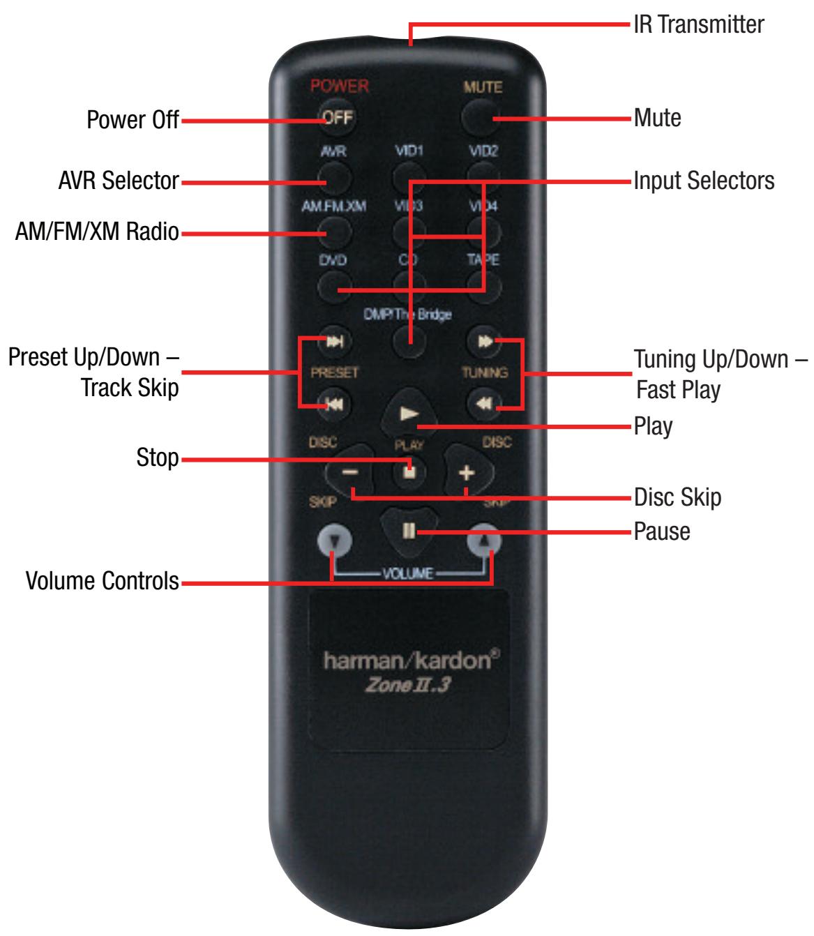
NOTE: To make it easier to follow the instructions throughout the manual that refer to this illustration, a copy of this page may be downloaded from the Product Support section at www.harmankardon.com.
INTRODUCTION TO HOME THEATER
The AVR 347 may be the first multichannel surround sound receiver you have owned. Although it has more connections and features than two-channel receivers, many of the principles are similar and the new concepts are easy to understand. This introductory section will help you to familiarize yourself with the basic concepts, which will make setup and operation smoother.
If you are already familiar with home theater, you may skip this section and proceed to the Connections section on page 19.
Typical Home Theater System
A home theater typically includes your audio/video receiver, which controls the system; a DVD player; a source component for television broadcasts, which may be a cable box, a satellite dish receiver, an HDTV tuner or simply an antenna connected to the TV; a video display (television); and loudspeakers.
All of these components are connected using various types of cables for audio and video signals.
Multichannel Audio
The main benefit of a home theater system is that several loudspeakers are used in various locations around the room to produce "surround sound." Surround sound immerses you in the musical or film presentation for increased realism.
The AVR 347 may have up to seven speakers connected directly to it (plus a subwoofer). Each main speaker is powered by its own amplifier channel inside the receiver. When more than two speakers are used, it is called a multichannel system.
- Front Left and Right - The main speakers are used the same way as in a 2-channel system. However, you may notice that in many surround modes, these speakers are used more for ambient sound while the main action, especially dialogue, is moved to the center speaker.
- Center - The center speaker is usually placed above or below the video screen, and is used mostly for dialogue in movies and television programs. This placement allows the dialogue to originate near the actors' faces, for a more natural sound.
- Surround Left and Right - The surround speakers are used to improve directionality of ambient sounds. In addition, by using more loudspeakers in the system, more dynamic soundtracks may be played without risk of overloading any one speaker.
- Surround Back Left and Right - Additional surround speakers may be placed behind the listening position, improving the precision with which ambient sounds may be placed and allowing for more realistic-sounding pans. By using more speakers in the system, the same sound levels may be attained with less burden placed on any individual speaker.
The surround back speakers may also be used with specialized surround modes that are designed for use with 7.1-channel systems, such as Dolby Digital EX, DTS-ES (Discrete and Matrix) and Logic 7 (7.1 modes). However, the surround back speakers are optional. In fact, the AVR 347 enables you to set up a 5.1-channel system in
your main listening area, and reassign the surround back channels for use with a multiroom system, in which you use the surround back channels to power a pair of loudspeakers located in another room.
Many people expect the surround speakers to play as loudly as the front speakers. Although all of the speakers in the system will be calibrated to sound equally loud at the listening position, most artists use the surround speakers for ambient effects only, and they program their materials to steer very little sound to these speakers.
- Subwoofer – A subwoofer is a special-purpose speaker designed to play only the lowest frequencies (the bass). It may be used to augment smaller, limited-range satellite speakers used for the other channels. In addition, many digital-format programs, such as movies recorded in Dolby Digital, contain a special low-frequency effects (LFE) channel which is directed only to the subwoofer. The LFE channel packs the punch of a rumbling train or airplane, or the power of an explosion, adding realism and excitement to your home theater. Many people use two subwoofoers, placed on the left and right sides of the room, for additional power and even distribution of the sound.
Surround Modes
There are different theories as to the best way to present surround sound and to distribute soundtrack information among the various speakers. A variety of algorithms have been developed in an effort to accurately reproduce the way we hear sounds in the real world. The result is a rich variety of surround mode options. Some modes are selected automatically, depending on the signal being received from the source. In many cases, you may select a surround mode manually.
Several companies have taken surround sound in slightly differing directions. It is helpful to group the numerous surround modes either by their brand name, or by using a generic name:
- Dolby Laboratories, Inc. Modes - Dolby Digital, Dolby Digital EX, Dolby Pro Logic II and IIx, Dolby Virtual Speaker, Dolby Headphone
- DTS Modes - DTS, DTS-ES (Discrete and Matrix), DTS Neo:6, DTS 96/24
- Harman International (Harman Kardon's Parent Company) – Logic 7
- DSP Modes - Generic modes that include Hall 1, Hall 2 and Theater
- Stereo Modes - Generic modes that expand upon conventional 2-channel stereo, including DSP Surround Off, Analog Bypass Surround Off and 5- and 7-Channel Stereo
Table 8 on pages 50-52 contains detailed explanations of the differences between the various mode groups, and the mode options available within each group. Digital modes, such as Dolby Digital and DTS, are only available with specially encoded programs, such as HDTV, DVDs and digital cable or satellite television. Other modes may be used with various digital and analog signals to create a different surround presentation, or to use a different number of speakers. Surround mode selection depends upon the number of speakers in your system, the materials you are watching or listening to, and your personal tastes. Feel free to experiment.
There are different types of audio and video connections used to connect the receiver to the speakers and video display, and to connect the source devices to the receiver. To make it easier to keep them all straight, the Consumer Electronics Association (CEA®) has established a color-coding standard. Table 1 may be helpful to you as a reference while you set up your system.
Table 1 - Connection Color Guide
| Audio Connections | ||
| Left | Right | |
| Front (FL/FR) | Center (C) | |
| Surround (SL/SR) | Surround Back (SBL/SBR) | |
| Subwoofer (SUB) | ||
| Digital Audio Connections | ||
| Coaxial | ||
| Optical | Input | Output |
| Video Connections | ||
| Component Y | Pb | Pr |
| Composite | ||
| S-Video | ||
| HDMI" Connections (digital audio/video) | ||
| HDMI | ||
Types of Connections
This section will briefly review different types of cables and connections that you may use to set up your system.
Speaker Connections
Speaker cables carry an amplified signal from the receiver's speaker terminals to each loudspeaker. Speaker cables contain two wire conductors, or leads, inside plastic insulation. The two conductors are usually differentiated in some way, by using different colors, or stripes, or even by adding a ridge to the insulation. Sometimes the actual wires are different, one being copper-colored and the other silver.
The differentiation is important because each speaker must be connected to the receiver's speaker-output terminals using two wires, one positive (+) and one negative (-), referred to as speaker polarity. It's important to maintain the proper polarity for all speakers in the system. If some speakers have their negative terminals connected to the receiver's positive terminals, performance can suffer, especially for the low frequencies.
Always connect the positive terminal on the loudspeaker, which is usually colored red, to the positive terminal on the receiver, which is colored as shown in the Connection Color Guide (Table 1). Similarly, always connect the black negative terminal on the speaker to the black negative terminal on the receiver.
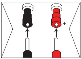
Figure 1 - Binding-Post Speaker Terminals With Banana Plugs
The AVR 347 uses binding-post speaker terminals that can accept banana plugs or bare-wire cables. Banana plugs are simply plugged into the hole in the middle of the terminal cap. See Figure 1.
Bare wire cables are installed as follows (see Figure 2):
- Unscrew the terminal cap until the pass-through hole in the collar is revealed.
- Insert the bare end of the wire into the hole.
- Hand-tighten the cap until the wire is held snugly.
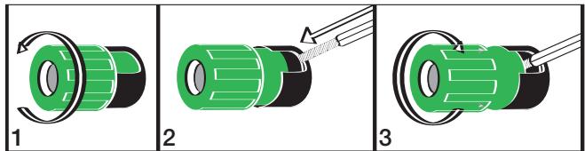
Figure 2 - Binding-Post Speaker Terminals With Bare Wires
Subwoofer
The subwoofer is a specialized type of loudspeaker that is usually connected in a different way. The subwoofer is used to play only the low frequencies (bass), which require much more power than the other speaker channels. In order to obtain the best results, most speaker manufacturers offer powered subwoofoers, in which the speaker contains its own amplifier on board. Sometimes the subwoofer is connected to the receiver using the front left and right speaker outputs, and then the front left and right speakers are connected to terminals on the subwoofer. More often, a line-level (nonamplified) connection is made from the receiver's Subwoofer Output to a corresponding jack on the subwoofer, as shown in Figure 3.
Although the subwoofer output looks similar to the analog audio jacks used for the various components, it is filtered and only allows the low frequencies to pass. Don't connect this output to any other devices. Although doing so won't cause any harm, performance will suffer.

Figure 3 - Subwoofer
Connecting Source Devices to the AVR
The AVR 347 is designed to process audio and video input signals, playing back the audio and displaying the video on a television or monitor connected to the AVR. These signals originate in what are known as "source devices," including your DVD player, CD player, DVR (digital video recorder) or other recorder, tape deck, game console, cable or satellite television box or MP3 player. Although the tuner is built into the AVR, it also counts as a source, even though no external connections are needed, other than the FM and AM antennas and the XM antenna module.
Separate connections are required for the audio and video portions of the signal, except for digital HDMI connections. The types of connections used depend upon what's available on the source device, and for video signals, the capabilities of your video display.
Audio Connections
There are two formats for audio connections: digital and analog. Digital audio signals are of higher quality, and are required for listening to sources encoded with digital surround modes, such as Dolby Digital and DTS. There are three types of digital audio connections: HDMI, coaxial and optical. Any one type of digital audio connection may be used for each source device, but never more than one for the same source. However, it's okay to make both analog and digital audio connections at the same time to the same source.
NOTE: Since the AVR 347 is capable of processing the audio and video portions of most HDMI signals, if your video display device has an HDMI input, you may make a single HDMI connection from your HDMI 1.1-or-higher source device (such as a DVD player) to the AVR. In that case, no separate digital audio connection is required. Make sure to turn the volume on your television all the way off.
Digital Audio
The AVR 347 is equipped with two HDMI (High-Definition Multimedia Interface) inputs, and one output. HDMI is capable of carrying digital audio and video information using a single cable, thus delivering the highest possible quality picture and sound.
The AVR 347 is Simplay HD-verified for compatibility via the HDMI connection with other Simplay HD-verified products.
There are different versions of HDMI, depending on the capability of the source device and the type of signal it is capable of transmitting via the HDMI connection.
In addition, receivers and processors such as the AVR 347 may handle the incoming signal in several different ways, depending on their capability as well. The AVR 347 uses HDMI version 1.1, and is capable of processing both the audio and video components of the HDMI data, minimizing the number of cable connections in your system.
NOTE: Some multichannel audio devices, such as DVD-Audio, SACD, HD-DVD or Blu-ray Disc players, output some audio formats only through the source's multichannel analog outputs. These include DVD-Audio players with HDMI version 1.0, and HD-DVD and Blu-ray Disc players that do not decode the digital audio. In those cases, make a separate analog audio connection in addition to the HDMI connection, which is still used for video or if you wish to listen to Dolby Digital, DTS or PCM materials that may be stored on the disc.
In addition, the AVR 347 will convert analog video signals to the HDMI format, upscaling to high-definition 720p resolution. Source signals with 1080i or 1080p resolution are passed via the HDMI Output to your display at their original high-quality resolution, depending on your display's capabilities. You may view the AVR 347's own on-screen display menus using the HDMI output.
IMPORTANT NOTE: The AVR 347 cannot convert 1080i or 1080p analog video signals to the HDMI format, but passes 1080i signals in their native format to the Component Video Outputs. This affects users of Microsoft® Xbox® 360 systems and some older set-top boxes. If your digital cable television set-top box outputs 1080i or better video via component video outputs and is not equipped with an HDMI output, contact your cable operator for a replacement.
For Xbox 360 and satellite television customers, either change the settings on your source device to ensure that it outputs only 720p video through its component video outputs, which the AVR can convert to the HDMI format, or connect the AVR's Component Video Monitor Outputs to the video display. Although you could connect the source device's component video outputs directly to your video display, you would then have to select the correct video input on the display, depending on which source input on the AVR was in use.
The physical HDMI connection is simple. The connector is shaped for easy plug-in (see Figure 4). If your video display has a DVI input, you may use an HDMI-to-DVI adapter (not included) to connect it to the AVR's HDMI Output.

Figure 4 - HDMI Connection
HDMI cable runs are usually limited to about 10 feet. The AVR 347 incorporates a repeater, which allows an additional 10 feet of cable between the source device and the video display.
If your video display or source device is not HDMI-capable, use one of the analog video connections (composite, S- or component video) and if available on your source device, either a coaxial or optical digital audio connection.
Coaxial digital audio jacks are usually color-coded in orange. Although they look similar to analog jacks, they should not be confused, and you should not connect coaxial digital audio outputs to analog inputs or vice versa. See Figure 5.
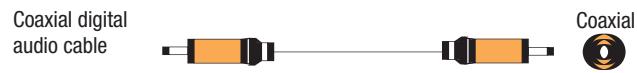
Figure 5 - Coaxial Digital Audio
Optical digital audio connectors are often covered by a shutter to protect them from dust. The shutter opens as the cable is inserted. Input connectors are color-coded using a black shutter, while outputs use a gray shutter. See Figure 6.
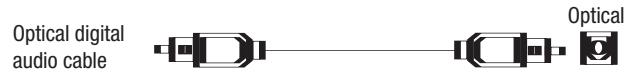
Figure 6 - Optical Digital Audio
Due to the nature of digital signals as binary bits, they aren't subject to signal degradation the way analog signals are. Therefore, the quality of all digital audio connections should be the same, although it is important to limit the length of the cable. Whichever type of connection you choose, Harman Kardon recommends that you always select the highest quality cables available within your budget.
Analog Audio
Analog connections require two cables, one for the left channel (white) and one for the right channel (red). These two cables are often attached to each other for most of their length. See Figure 7.
Most sources that have digital audio jacks also have analog audio jacks, although some older types of sources, such as tape decks, have only analog jacks. For sources that are capable of both digital and analog audio, you may wish to make both connections.
The analog audio connection is strongly recommended if you intend to use the source with the multiroom system. It's required if you will be using the multiroom preamp outputs with an external amplifier to power your remote speakers, as the AVR 347's multiroom system is not capable of converting the digital signal to analog format. It's suggested that you also use the analog audio connections when using the surround back/multiroom speaker outputs, in case another two-channel digital audio source is in use in the main listening area. The AVR 347 is only capable of processing one PCM source at a time.
If you wish to record materials from DVDs or other copy-protected sources, you may only do so using analog connections. Remember to comply with all copyright laws, if you choose to make a copy for your own personal use.
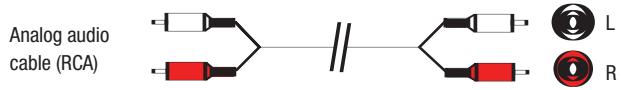
Figure 7 - Analog Audio
Multichannel analog connections are used with some high-definition sources where the copy-protected digital content is decoded inside the source. These types of connections are usually used with DVD-Audio, SACD, Blu-ray Disc, HD-DVD and other multichannel players. See Figure 8. However, the multichannel analog audio connection is not required for DVD-Audio players compliant with HDMI version 1.1 or better, or HD-DVD and Blu-ray Disc players that decode the digital audio internally and output linear PCM signals in digital format. Consult the owner's guide for your disc player for more information.
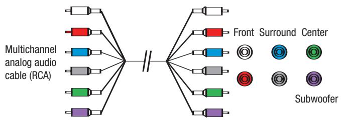
Figure 8 - Multichannel Analog Audio
Harman Kardon receivers also include a proprietary, dedicated audio connection called "The Bridge/DMP". If you own an iPod with a dock connector, you may separately purchase The Bridge and connect it to The Bridge/DMP port on the receiver. See Figure 9. Dock your iPod (not included) in The Bridge, and you may listen to your audio materials through your high-performance audio system. If your iPod is photo- or video-capable, you may view still images or video materials stored on the iPod using your home theater system. You may even use the
AVR 347 remote to control the iPod, with navigation messages displayed on the front panel and on a video display connected to the AVR. The Bridge outputs analog audio to the AVR 347, and it is available to the multiroom system.

Figure 9 - The Bridge
Video Connections
Although some sources produce an audio signal only (e.g., CD player, tape deck), many sources output both audio and video signals (e.g., DVD player, cable television box, HDTV tuner, satellite box, VCR, DVR). In addition to the audio connection, you will need to connect one type of video connection for each source (never more than one at the same time for any source).
Digital Video
If you have already connected a source device to one of the HDMI inputs as explained in the Digital Audio Connections section, then you have automatically made a video connection at the same time, as the HDMI signal includes both digital audio and video components.
If the source device is not capable of transmitting its digital audio signal through the HDMI connection, then use one of the coaxial or optical digital audio inputs for the source.
If a multichannel analog audio connection is required for certain lossless formats (e.g., DVD-Audio, SACD, HD-DVD or Blu-ray Disc), you may make both audio connections, but you must also make an analog video connection. To listen to the multichannel disc, first select the analog video source input, then select the 6-/8-channel analog audio inputs, and the AVR will retain the last video source you selected other than HDMI.
The AVR 347 is Simplay HD-verified for compatibility via the HDMI connection with other Simplay HD-verified products.

Figure 4 (repeated) - HDMI Connection
Analog Video
There are three types of analog video connections: composite video, S-video and component video. Composite video is the basic connection most commonly available. The jack is usually color-coded yellow, and looks like an analog audio jack, although it is important never to confuse the two. Do not plug a composite video cable into an analog or coaxial digital audio jack, or vice versa. Both the chrominance (color) and luminance (intensity) components of the video signal are transmitted using a single cable. See Figure 10.

Figure 10 - Composite Video
S-video, or "separate" video, transmits the chrominance and luminance components using separate wires contained within a single cable. The
plug on an S-video cable contains four metal pins, plus a plastic guide pin. Be careful to line up the plug correctly when you insert it into the jack on the receiver, source or video display. See Figure 11.

Figure 11 - S-Video
Component video separates the video signal into three components - one luminance ("Y") and two sub-sampled color signals ("Pb" and "Pr") - that are transmitted using three separate cables. The "Y" cable is color-coded green, the "Pb" cable is colored blue and the "Pr" cable is colored red. See Figure 12.
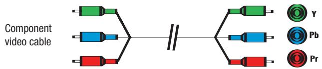
Figure 12 - Component Video
If it's available on your video display, HDMI is recommended as the best quality connection, followed by component video, S-video and then composite video.
NOTES:
- Due to copy-protection restrictions, there is no output at the Component Video Monitor Outputs for copy-protected sources.
- High-resolution 1080i and 1080p video signals are not available at the HDMI Output, but 1080i signals are passed through, as is, to the Component Video Outputs. If your source outputs analog high-resolution video, either use the Component Video Outputs, change the output resolution of your source device to 720p, or connect your source's component video outputs directly to your video display.
- Due to the design of some video displays, analog 480p or 720p component video source signals may produce artifacts when used with the AVR's analog video outputs (composite, S-video or component video). If this occurs, try changing the Video Mode setting in the INPUT SETUP menu, or connecting the source device's video output directly to your video display. However, for best results, we recommend that you consider upgrading to an HDMI-capable video display.
Antennas
The AVR 347 uses separate terminals for the included FM and AM antennas that provide proper reception for the tuner.
The FM antenna uses a 75-ohm F-connector. See Figure 13.

Figure 13 - FM Antenna
The AM loop antenna needs to be assembled. Then connect the two leads to the screw terminals on the receiver. See Figure 14.
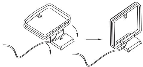
Figure 14 - AM Antenna
RS-232 Serial Port
The RS-232 serial port on the AVR 347 is used only for data. If Harman Kardon releases a software upgrade for the receiver's operating system at some time in the future, the upgrade may be downloaded to the AVR using this port. Complete instructions will be provided at that time.
Before you begin to connect cables, it is important to place your speakers in their correct locations in the room.
Optimally, the speakers should be placed in a circle with the listening position at its center. The distance from the listening position to the video display forms the radius of the circle.
The speakers should be angled so that they directly face the listening position.
Front Speaker Placement
The center speaker is placed either on top of, below or mounted on the wall above or below the video display screen.
The front left and right speakers are placed along the circle, about 30 degrees from the center speaker and angled toward the listener.
It is best to place the front left/right and center speakers as close to the same height as possible, preferably at about the same height as the listener's ears. In any event, the center speaker should be no more than two feet above or below the left/right speakers.
Placement of the surround speakers depends on the number of speakers in your system. If you're using only two speakers with the AVR 347, place them in the front left and right positions, and skip to the Installation section. However, Harman Kardon recommends using the AVR 347 in a 5.1- or 7.1-channel configuration for optimal surround sound performance.
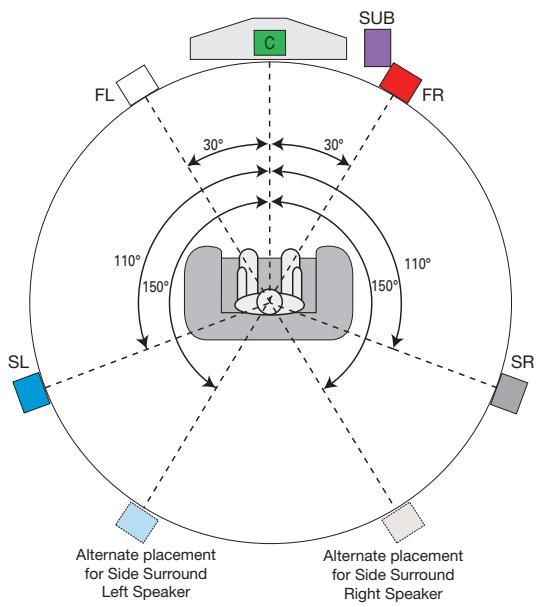
Figure 15 - Speaker Placement (5.1-Channel System)
Placement of Surround Speakers in a 5.1-Channel System
The side surround speakers should be placed 110 degrees from the center speaker; that is, slightly behind and angled toward the listener. If this isn't feasible, place them behind the listener, with each surround speaker facing the opposite-side front speaker. See Figure 15. The surround speakers may be placed a little higher than the listener's ears.
Placement of Surround Speakers in a 7.1-Channel System
In a 7.1-channel system, the side surround speakers are placed 90 degrees from the center speaker, directly to either side of the listening position, which is different than in a 5.1-channel system. The surround back left and right speakers are placed 150 degrees from the center speaker, or directly facing the opposite-side front speaker. See Figure 16.
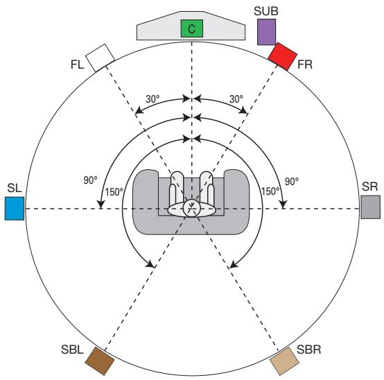
Figure 16 - Speaker Placement (7.1-Channel System)
NOTE: Some speaker manufacturers offer 6.1-channel speaker systems, which are compatible with the 6.1-channel digital surround sound formats available on DVD and elsewhere, such as Dolby Digital EX and DTS-ES Discrete and Matrix modes. We do not recommend using the AVR 347 in a 6.1-channel configuration. In fact, the 6.1-channel formats will sound better when played through a 7.1-channel system. The same surround back channel information is played through both surround back speakers, but with twice the power and clarity.
If you wish to use the AVR 347 with a 6.1-channel speaker system, place the single surround back speaker directly behind the listener, but do not connect it until after you have run the EzSet/EQ procedure for a 5.1-channel system. After EzSet/EQ finishes, connect the surround back speaker to the Surround Back Left Speaker Output. You will then need to follow the directions in the Advanced Features section for manual setup of the surround back speaker.
Subwoofer Placement
The subwoofer's location is less critical, since low-frequency sounds are omnidirectional. Placing the subwoofer close to a wall or in a corner will reinforce the low frequencies, and may create a "boomy" sound. You may wish to experiment over time by placing the subwoofer where the listener normally sits and then walking around the room until the low frequencies sound best. Place the subwoofer in that spot.
NOTE: Your receiver will sound its best when the same model loudspeaker is used for all positions (other than the subwoofer). If that isn't possible, try to use speakers made by the same manufacturer.
You are now ready to connect your various components to your receiver. Before beginning, make sure that all components, including the AVR 347, are turned completely off and their power cords are unplugged. Don't plug any of the power cords back in until you have finished making all of your connections.
Remember that your receiver generates heat while it is on. Select a location that leaves several inches of space on all sides of the receiver. It is preferable to avoid completely enclosing the receiver inside a cabinet. It is also preferable to place components on separate shelves rather than stacking them directly on top of the receiver. Some surface finishes are delicate. Try to select a location with a sturdy surface finish.
Step One – Connect the Speakers
If you have not yet done so, place your speakers in the listening room, as described in the Speaker Placement section above.
Connect the center, front left, front right, surround left, surround right, surround back left and surround back right loudspeakers to the corresponding speaker terminals on the AVR 347. See Figure 17. Remember to maintain the proper polarity by always connecting the positive and negative terminals on each speaker to the positive and negative terminals on the receiver. Use the Connection Color Guide on page 19 as a reference.
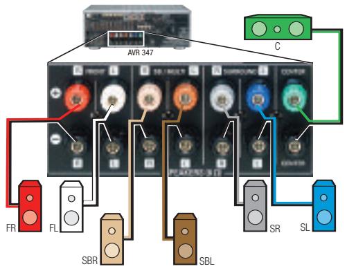
Figure 17 - Speaker Connections
NOTE: If you only have one surround back speaker, wait until after you have run EzSet/EQ in the Initial Setup section before connecting it to the Surround Back Left speaker outputs.
Step Two - Connect the Subwoofer
Connect the Subwoofer Output on the AVR 347 to the line-level input on your subwoofer. See Figure 18. Consult the manufacturer's guide for the subwoofer for additional information.
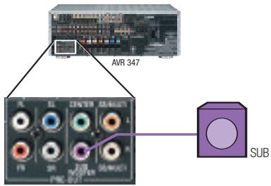
Figure 18 - Subwoofer Connection
Step Three – Connect the Antennas
Connect the FM and AM antennas to their terminals. If you have purchased an XM antenna module designed for connection to an XM Ready device, such as the AVR 347, you may connect it now. To enjoy XM Radio, remember to purchase a subscription and activate your antenna module. More information is available at www.xmradio.com. See Figure 19.
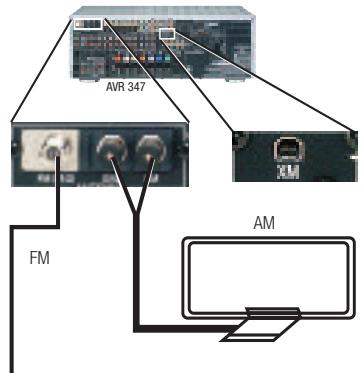
Figure 19 - Antenna Connections
Step Four – Connect the Source Components
Use the Table A4 worksheet in the Appendix to note which connections you will use for each of your source devices.
For each source, select a source input (Video 1, Video 2, Video 3, etc.). In Table 2 we recommend connecting certain types of sources to certain source inputs to make it easier to program and use the remote control.
Decide which audio connections you will use. If your source device has them, use one of the HDMI, coaxial digital or the optical digital audio connection. Referring to Table 2, we recommend that you connect the DVD source to the Coaxial 1 input jack, and the source designated Video 2 to the Optical 1 input jack. If you are using the HDMI inputs, then in most cases no other audio connection is required. If your source outputs video but not audio via its HDMI connection, then select any available digital audio input on the AVR to use with the source. If your HDMI source plays DVD-Audio, SACD, HD-DVD, Blu-ray Discs or another multichannel audio format, connect its multichannel analog audio outputs to the AVR 347's 6-/8-Channel Inputs, and connect one of its analog video outputs to a source input on the AVR 347 (e.g., Component Video 3 or Video 3). When you select that source input, e.g., Video 3, select the 6-/8-Channel Inputs, and the AVR will automatically use the analog video input.
NOTE: The multichannel analog audio connection is not required for DVD-Audio players compliant with HDMI version 1.1 or better, or HD-DVD and Blu-ray Disc players that decode the digital audio internally and output linear PCM signals in digital format. Consult the owner's guide for your disc player for more information.
In addition to the digital audio connections, we recommend that you connect the analog audio connections for each source, as a backup to the digital connections, for recording, for use with the multiroom system, or in the event that you use all eight of the digital audio inputs for other devices. For sources that don't have digital audio outputs, you must use the analog audio connections.
For each video source, select one type of video connection. HDMI video is preferred, but both your source device and your video display must have this type of video capability. If either device does not, then use component video, S-video or composite video.
Referring to Table 2, we recommend that you connect the DVD source to the Component Video 1 inputs, the Video 1 source to the Component Video 2 inputs, and the Video 2 source to the Component Video 3 inputs. Any HDMI-capable source devices should be connected to one of the two HDMI inputs. All other source devices should be connected to either the component, S- or composite video input for that source. However, you may make whatever video connections are best for your system.
NOTE: It's possible for a source to use none of the connections named for that source. For example, you might connect your DVD player to the Component Video 1 inputs and the Coax 1 digital audio input. However, we will refer to this source as "DVD," and in the Initial Setup section you will program the receiver so that these connections are assigned to the DVD source. When you select "DVD" as your source using the front panel or the remote, the correct connections for your DVD player will be used.
We recommend connecting your various sources using the connections shown in Table 2 (below) in order to simplify programming your receiver and remote control. However, you may connect any device to any source input.
Table 2 - Recommended Source Component Connections
| Source Device Type | AVR 347 Source Input | Audio Connections | Video Connections |
| VCR, DVR, PVR, TiVo or other audio/video recorder | Video 1 | ● Video 1 Analog (inputs and outputs) and ● Any one available coaxial or optical digital, audio input, with corresponding coax or optical digital output | ● One of Component Video 2, Video 1 S-video or Video 1 Composite Video Input ● For recording, use Video 1 S-video or Composite Video Output, and do not use component video connections at all |
| Cable TV, satellite TV, HDTV or other device that delivers television programs | Video 2 | ● Video 2 Analog Inputs and ● Optical 1 Input | ● One of Component Video 3, Video 2 S-video or Video 2 Composite Video Input |
| TV or other audio/video device (only when used as a source) | Video 3 | ● Video 3 Analog Inputs and ● Any one available coaxial or optical digital audio input | ● Video 3 S-video or Video 3 Composite Video Input ● Not required if source is a TV |
| TV, game console, camera or other audio/video device | Video 4 (front-panel jacks) | ● Video 4 Analog Inputs and ● Either Coax 3 or Optical 3 Input | ● Video 4 S-video or Video 4 Composite Video Input ● Not required if source is a TV |
| DVD Audio/Video, SACD, HD-DVD, Blu-ray Disc | DVD | ● DVD Analog Inputs ● 6-/8-Channel Inputs (optional) and ● Coax 1 Input | ● Component Video 1 Input |
| HDMI-capable DVD Audio/Video or HD-DVD player or other audio/video device | HDMI 1 | ● HDMI 1 Input ● 6-/8-Channel Inputs (optional) | ● HDMI 1 Input |
| HDMI-capable DVD Audio/Video or HD-DVD player or other audio/video device | HDMI 2 | ● HDMI 2 Input ● 6-/8-Channel Inputs (optional) | ● HDMI 2 Input |
| CD player | CD | ● CD Analog Inputs and ● Any one available coaxial or optical digital audio input | ● Not required |
| CDR, MiniDisc, cassette | Tape | ● Tape Analog (inputs and outputs) and ● Any one available coaxial or optical digital, audio input, with corresponding output or optical digital output | ● Not required |
NOTE: The AVR 347 is equipped with a total of eight digital audio inputs, not including the HDMI inputs: six on the rear panel (Coaxial 1, 2 and 3, Optical 1, 2 and 3) and two on the front panel (Coaxial 4 and Optical 4). However, there are a total of nine sources that may be connected to devices that have digital audio outputs. We recommend certain digital audio connections simply because, as reflected in Table A1 of the Appendix, those digital audio inputs are assigned to those sources by default at the factory. But any digital audio input (except HDMI) may be reassigned to any source. Since you may not be using all nine source inputs, you may reassign a digital audio input that is recommended for a source you aren't using to another device. Table 2 is a guide; you may need to make adjustments to fit your system.
Video 1 Source
Since this source includes audio and video recording output jacks, it is best suited to a video recorder, such as your VCR or DVR/PVR.
Referring to Table 2, connect your recorder to the Video 1 Analog Audio inputs and outputs and to any available coaxial or optical digital audio input (and corresponding digital audio output). See Figure 20. Use either the Video 1 S-video or composite video input and output if you wish to make recordings. If you don't plan on recording, you may use the Component Video 2 inputs.
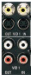
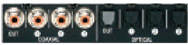
Figure 20 - Video 1 AV Inputs and Outputs, and Digital Audio Inputs and Outputs
Remember to connect the audio and video output jacks on your recorder to the Video 1 or digital audio input jacks on the AVR, and the audio and video input jacks on your recorder to the Video 1 or digital audio output jacks on the AVR.
NOTE: It isn't possible to make recordings using component video or HDMI connections. Keep this in mind as you connect other source devices that you may wish to make recordings from.
Video 2 Source
The Video 2 source is used only for playback. The AVR 347 remote control is programmed to operate many brands and models of cable and satellite television devices, and we recommend connecting your cable or satellite set-top box to this source.
Referring to Table 2, connect your set-top box to the Video 2 Analog Audio inputs and to the Optical 1 Digital Audio input. If possible, use the Component Video 3 inputs. Otherwise, connect the set-top box's S-video or composite video output to the matching Video 2 video input. See Figure 21.
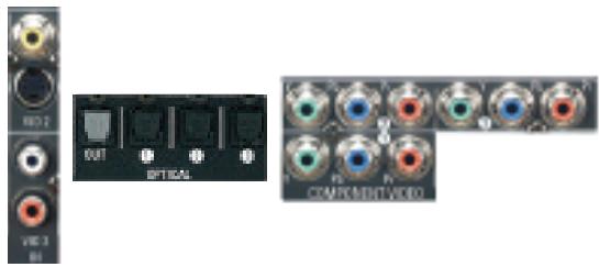
Figure 21 - Video 2 AV, Digital Audio and Component Video Inputs
Video 3 Source
The Video 3 source is used for playback only. The remote control is programmed to operate a TV, but you may connect any audio/video source device to the Video 3 inputs and use the device's own remote to control it.
If you receive your television programming using your TV with an antenna or direct cable connection, connect the analog audio outputs (if available on your TV) to the Video 3 Analog Audio inputs. See Figure 22. Do not connect any video output on the television set to any video input on the receiver. See Step Five for information on connecting the receiver's video monitor outputs to the TV.
NOTE: You may connect any video source other than a display device to the Video 3 S-video or composite video inputs.
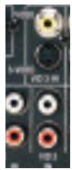
Figure 22 - Video 3 AW Inputs
Video 4 Source
The Video 4 source is used only for playback. It is also generally reserved for components that are only temporarily connected to the receiver, such as cameras and game consoles. When not in use, you may place the supplied covers over the front-panel Video 4 jacks for a cleaner appearance. Simply snap the covers in place. When you wish to use the jacks, gently press on the left side of each cover to pivot it out for removal.
Referring to Table 2, connect your camera or game console to the Video 4 Analog Audio inputs and to either the Coaxial 4 or Optical 4 digital audio input. Connect the component's S-video or composite video output to the matching Video 4 video input. See Figure 23.

Figure 23 - Video 4 A/V and Digital Audio Inputs
NOTE: The Video 4 Input Selector on the remote may be programmed to operate a television or video display only.
IMPORTANT NOTE FOR MICROSOFT®XBOX®360USERS:
The Microsoft Xbox 360 gaming system is capable of outputting high-definition 1080i and 1080p video signals using the analog component video outputs. Since the AVR 347 is not capable of converting these analog component video signals to the HDMI format, although 1080i signals are passed through, as is, to the Component Video Outputs, to view your Xbox 360's video output, connect the AVR's or Xbox's component video outputs to your video display, or change your Xbox 360's settings so that it outputs 720p video, which the AVR 347 can then convert to the HDMI format.
DVD
The DVD source is used for a DVD player. If you have a more advanced multichannel device, such as a Blu-ray Disc or HD-DVD player, you may connect it to the DVD source, or to one of the HDMI sources.
Referring to Table 2, connect your DVD player to the DVD Analog Audio inputs and to the Coaxial 1 Digital Audio input. If possible, use the Component Video 1 inputs. Otherwise, connect the DVD player's S-video or composite video output to the matching DVD video input. See Figure 24.
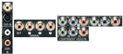
Figure 24 - DVD AV, Digital Audio and Component Video Inputs
If your DVD player plays multichannel lossless discs, such as SACD or DVD-Audio, or when an HD-DVD or Blu-ray Disc player is used, you may also need to connect the 6- or 8-channel analog audio outputs on the player to the 6-/8-channel analog audio inputs on the receiver, in order to enjoy these discs to their fullest. See Figure 25.
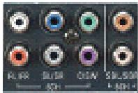
Figure 25 - 6-/8-Channel Analog Audio Inputs
NOTE: The multichannel analog audio connection is not required for DVD-Audio players compliant with HDMI version 1.1 or better, or HD-DVD and Blu-ray Disc players that decode the digital audio internally and output linear PCM signals in digital format. Consult the owner's guide for your disc player for more information.
HDMI 1 and 2
The HDMI sources are used with devices that are capable of outputting digital, audio and video through an HDMI connection, such as an HD-DVD or Blu-ray Disc player or HDTV tuner. The HDMI 1 and 2 sources are not used with any of the 2-channel analog audio or video inputs on the AVR 347.
Make sure your video display is HDMI-capable, and for many source devices, the display must be HDCP-compliant (High-Bandwidth Digital
Content Protection) in order to display copy-protected materials. If the source device is not capable of outputting digital audio via its HDMI output, connect its coaxial or optical digital audio output to an available input on the AVR. If the source device plays multichannel discs (e.g., DVD-Audio, SACD, HD-DVD, Blu-ray Disc), connect its multichannel analog audio outputs to the AVR 347's 6-/8-Channel Inputs (but see the note that follows Figure 25). Connect one of the source's analog video outputs to a source input on the AVR (e.g., Component Video 3 or Video 3) and select that source input, then select the 6-/8-Channel Inputs for audio; the AVR 347 will retain the last video selection other than HDMI. See Figure 26.
The AVR 347 is Simplay HD-verified for compatibility via the HDMI connection with other Simplay HD-verified products.
If your video display is equipped with a DVI (Digital Video Interface) input, you may use an HDMI-to-DVI adapter (not included).


Figure 26 - HDMI and Digital Audio Inputs
CD
The CD source is used for a strictly audio device, such as a CD player.
Referring to Table 2, connect your CD player to the CD Analog Audio inputs and to any available digital audio input. See Figure 27.
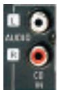

Figure 27 - CD Audio Inputs and Digital Audio Inputs
No video connections are needed.
Tape
The Tape source is used for audio-only recorders, such as a CDR, MiniDisc or cassette deck.
Referring to Table 2, connect your recorder to the Tape Analog Audio inputs and outputs, and to any available digital audio input (and corresponding digital audio output). See Figure 28.
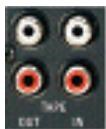
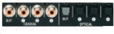
Figure 28 - Tape Audio Inputs and Outputs, and Digital Audio Inputs and Outputs
Remember to connect the output jacks on your recorder to the Tape or digital audio input jacks on the AVR, and the input jacks on your recorder to the Tape or digital audio output jacks on the AVR.
No video connections are needed.
The Bridge
With Harman Kardon's optional The Bridge, you can listen to audio or view videos stored on your iPod (not included), use your AVR 347
remote control to operate the iPod, and even charge the iPod while it's docked in The Bridge.
Simply plug the proprietary cable from The Bridge into the special The Bridge/DMP connector on the rear of the AVR 347. See Figure 29. Refer to the owner's manual for The Bridge to select the appropriate insert to match your iPod.

Figure 29 - The Bridge/DMP Connector
Step Five – Connect Video Display
Only video connections should be made between the receiver and your video display (TV), unless your TV is the source for your television programming (see Video 3 Source on page 26).
If you used an HDMI video connection for any of your sources, then connect the HDMI Output on the AVR to an HDMI input on your video display. See Figure 30. Consult the owner's guide for your television to learn the proper procedure for disabling or muting the audio. Unless you have a non-HDMI source device that outputs 1080i or higher video via an analog component video connection (see note below), no other video connections are required, thanks to the AVR 347's ability to transcode analog video signals to HDMI, and you may proceed to Step Six.
IMPORTANT NOTE: The AVR 347 cannot convert 1080i or 1080p analog video signals to the HDMI format and outputs 1080i signals, as is, to the Component Video Outputs. This affects users of Microsoft Xbox 360 systems and some older set-top boxes.
If your digital cable television set-top box outputs 1080i or higher video via component video outputs only contact your cable operator for a replacement unit equipped with an HDM output.
For Xbox 360 or satellite receivers with no HDMI output, connect the AVR's Component Video Monitor Outputs to the TV, or change the settings on your source device so that it outputs only 720p video through its component video outputs, which the AVR can convert to the HDMI format. Although you could connect the source device's component video outputs directly to your video display, you would then have to select the correct video input on the display to match the AVR's input.

Figure 30 - HDMI Output
If your television does not have HDMI or DVI video inputs, you will need to make a video connection for each type of video used for your sources.
First, determine what types of video your display is capable of handling. Component video is preferred, followed by S-video and then composite video. Ideally, this guided you in selecting the video connections for your sources.
Next, note which types of video connections you used for your source devices. Make sure you didn't use a better type of video connection for a source than your video display can handle. If so, disconnect the source and use a video connection that's compatible with your display.
If you used component video for any sources, connect the Component Video Monitor Outputs on the receiver to one set of component video inputs on your display. See Figure 31. The AVR 347 is able to transcode composite and S-video sources to component video. If your video display has component video inputs, then you need only to connect the Component Video Monitor Outputs and you may proceed to Step Six.
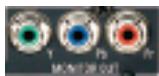
Figure 31 - Component Video Monitor Outputs
If you used S-video for any sources, connect the S-video Monitor output on the receiver to an S-video input on your display. See Figure 32. The AVR 347 converts composite video sources to S-video. If your video display has S-video inputs, then you need only to connect the S-Video Monitor Output and you may proceed to Step Six.
If you used composite video for any sources, but not component video or S-video, connect the Composite Video Monitor output on the receiver to a composite video input on the display. See Figure 32.

Figure 32 - S-Video and Composite Video Monitor Outputs
Consult the manual for your TV to make sure you understand how to select each video input.
Step Six - Plug in AC Power
Having made all of your wiring connections, it is now time to plug each component's AC power cord into a working outlet.
You may plug one device into the AC Switched Accessory Outlet on the rear of the AVR 347. See Figure 33. Make sure this device draws no more than 50 watts. The device should have its mechanical or master power switch turned on, and it will power on any time the AVR 347 is turned on.
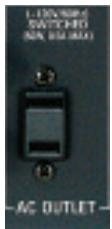
Figure 33 - Switched AC Accessory Outlet
Before plugging the AVR 347's AC Power Cord into an electrical outlet, make sure that the Master Power Switch on the front panel is popped out so that the word OFF appears on its top. Gently press the button to turn the switch off. This will prevent the possibility of damaging the AVR in case of a transient power surge.
The AVR 347 is equipped with a detachable power cord. It allows you to fully wire your system before installing the AVR, which may be required for some in-wall entertainment centers or custom applications. The male end of the cord should be plugged into an unswitched AC power outlet, and the female end should be plugged into the receptacle on the AVR 347's rear panel. See Figure 34.
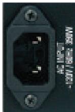
Figure 34 - AC Power Input
Step Seven - Insert Batteries in Remote
The AVR 347 remote control uses three AAA batteries, which are included.
To remove the battery cover located on the back of the remote, firmly press the ridged depression and slide the cover toward the top of the remote.
Insert the batteries, as shown in Figure 35, making sure to observe the correct polarity.
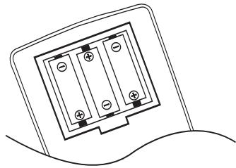
Figure 35 - Remote Battery Compartment
When using the remote, remember to point the lens toward the front panel of the AVR 347. Make sure no objects, such as furniture, are blocking the remote's path to the receiver. Bright lights, fluorescent lights and plasma video displays may interfere with the remote's functioning. The remote has a range of about 20 feet, depending on the lighting conditions. It may be used at an angle of up to 30 degrees to either side of the AVR.
If the remote seems to operate intermittently, or if pressing a button on the remote does not cause the AVR Selector or one of the Input Selectors to light up, then make sure the batteries have been inserted correctly, or replace all three batteries with fresh ones.
Step Eight – Program Sources Into the Remote
The AVR 347 remote not only is capable of controlling the receiver, but it may also be programmed to control many brands and models of VCRs, DVD players, CD players, cable boxes, satellite receivers, cassette decks and TVs, as well as an iPod docked in The Bridge.
It may help to think of the remote as a book with pages. Each "page" represents the button functions for a different device. In order to access the functions for a particular device, you first need to turn to that page; that is, switch the remote to that device mode. This is done by pressing the AVR Button to access the codes that control the receiver, or the Input Selector Buttons to access the codes for the devices programmed into the remote.
You may have noticed that three of the Input Selectors look different from the others (see Figure 36). For the DVD/CD, TAPE/The Bridge and HDMI 1/HDMI 2 Selectors, there is a primary source, the name of which is printed on the button, and a secondary source, the name of which is printed in green above the button.
When the remote is in the device mode for the primary source, e.g., DVD, pressing the device selector will cause it to light up in red. When the remote is in the secondary source's device mode, the selector will light up in green when pressed.
To switch between the primary and secondary device modes, press the selector twice quickly in succession. The selector will retain this selection until the next time you toggle between the primary and secondary device modes. That is, if you press the DVD/CD Selector twice quickly so that the CD source is activated, then press another source selector, such as Video 1, the next time you press the DVD/CD Selector, the remote will return to the CD device mode.
The AVR 347's remote is factory-programmed to control an iPod docked in The Bridge and many Harman Kardon DVD and CD players. If you have other source devices in your system, follow these steps to program the correct codes into the remote.
- Using the codes in Tables A9-A16 of the Appendix, look up the product type (e.g., DVD, cable TV box) and the brand name of your source. The number(s) listed is/are potential candidates for the correct code set for your particular device.
- Turn on your source device.
- This step places the remote in program mode, and varies slightly, depending on which Input Selector is being programmed. Refer to Figure 36.
a) DVD, Tape, Video 1, Video 2, Video 3 and Video 4 Sources: Press and hold the Input Selector until the Program Indicator LED starts to flash, then release it. Follow the directions in Step 4, below.
b) CD Source: Press the DVD/CD Input Selector twice quickly so that it turns green, hold it until the Program LED starts to flash, then release. Follow the directions in Step 4, below.
c) HDMI 1 Source: Press and hold the Input Selector until it turns red and the Program LED flashes, then release it. Next, press the Input Selector that corresponds to the device type you want to program into the HDMI 1 mode, i.e., DVD, VCR/PVR or CBL/SAT. Then follow the directions in Step 4, below.
d) HDMI 2 Source: Press and release the Input Selector once, then quickly press the Input Selector again so that it turns green. Hold it until the Program LED starts to flash, then release it. Next, press the Input Selector that corresponds to the device type you want to program into the HDMI 2 mode, i.e., DVD, VCR/PVR or CBL/SAT. Then follow the directions in Step 4, below.
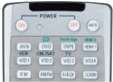
Figure 36 - Input Selectors
- Enter a code from Step 1, above.
a) If the device turns off, then press the Input Selector again to accept the code; it will flash. The remote will exit the Program mode.
b) If the device does not turn off, try entering another code. If you run out of codes, you may search through all of the codes in the remote's library for that product type by pressing the or . Button repeatedly until the device turns off. When the device turns off, enter the code by pressing the Input Selector, which will flash. The remote then exits Program mode.
- Once you have programmed a code, it's a good idea to try using some other functions to control the device. Sometimes, manufacturers use the same Power code for several different models, while other codes will vary. You may wish to repeat this process until you've programmed a satisfactory code set that operates most of the functions you frequently use.
- You may find out which code number you have programmed by pressing and holding the Input Selector to enter the Program mode. Then press the Set Button, and the LED will flash in the code sequence. One flash represents "1", two flashes for "2", and so forth. A series of many fast flashes represents "0". Record the codes programmed for each device in Table 3.
Table 3 - Remote Control Codes
| Source Input | Product Type (circle one) | Remote Control Code |
| Video 1 | VCR, PVR | |
| Video 2 | Cable, Satellite | |
| Video 3 | TV | |
| Video 4 | TV | |
| HDMI 1 | DVD, PVR, CBL, SAT | |
| HDMI 2 | DVD, PVR, CBL, SAT | |
| DVD | DVD | |
| CD | CD, CDR |
After you have programmed a code set to operate a device, test the functions to see which ones may be missing or not operating correctly. You may "learn" individual key codes if you have the device's original remote control by following this procedure:
a) Place the two remotes so that their IR transmitters face each other end to end, separated by about one inch. See Figure 37. The AVR 347 remote's transmitter also serves as an IR receiver during the learning process.

Figure 37 - AVR 347 and Original Remote Head-to-Head
b) Press the Input Selector for the device mode you wish to learn a code into, and place the AVR 347 remote in Learning mode by pressing and holding the Learn Button until the Program Indicator flashes in amber, then release. See Figure 38.
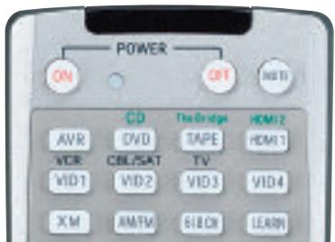
Figure 38 - Learning Remote Commands
c) Press the button on the AVR 347 remote you wish to program with the new code, and the Program Indicator will light steadily in amber.
d) Press and hold the button on the device's original remote whose code you wish to "learn" until the Program Indicator flashes in green, then release it.
e) You may program additional buttons by repeating steps c) and d).
Press the Learn button once to exit Learning mode. If you prefer, you may wait for the remote to "time out" and exit Learning mode on its own, but this will take about 30 seconds.
If you are unable to locate a code set that correctly operates your source device, it will not be possible to use the AVR remote to control that device. However, you may still connect the source to the AVR 347 and operate it using the device's original remote control. Alternatively, you may wish to consider purchasing Harman Kardon's optional TC 30 activity-based remote, which is programmed by accessing a large database of product codes on the Internet. The TC 30 is also capable of "learning" codes from your device's original remote.
Most of the button labels on the remote describe the button's function when used to control the AVR 347. However, the button may perform a very different function when used to control another device. Refer to the Remote Control Function List, Table A8 in the Appendix, for a list of each button's functions with the various product types.
If you wish, you may program Macros, which are preprogrammed code sequences that execute many code commands with a single button press. You may also program "punch-through" codes, which allow the remote to operate the volume, channel or transport controls of another device without having to switch the remote's device mode. See pages 60-61 for instructions on these advanced programming functions.
NOTE: The AVR 347 remote is preprogrammed to operate the transport controls of Harman Kardon DVD players when the AVR, the Video 2 (cable/satellite) or the Video 3 (TV) source is selected. You may change this punch-through programming at any time.
Step Nine – Remote IR Inputs and Output (Optional)
The AVR 347 is equipped with a Remote IR Input, a Multiroom IR Input and both full-carrier and stripped Remote IR Outputs to facilitate use of your system with a remote control in a variety of situations. See Figure 39.

Figure 39 - IR Inputs and Outputs
When the AVR 347 is placed in such a way that aiming the remote at the front-panel IR sensor is difficult, such as inside a cabinet or facing away from the listener, you may connect an external IR receiver, such as the optional Harman Kardon HE 1000, to the Remote IR Input jack. When you are using the AVR 347 in multiroom mode, you may connect an optional IR receiver, keypad or other control device to the Multiroom IR Input for remote control of the AVR 347 (and any sources connected to the AVR's Remote IR Output) from the remote zone. Any signals transmitted through the Multiroom IR Input will only control source selection and volume for the remote zone. If a source device is being shared with the main listening area, then any control commands issued to that source will also affect the main room.
If any of your source devices are equipped with a compatible Remote IR Input, you may use a 1/8'' mini- plug interconnect cable (not included) to connect the AVR's Remote IR Output to the source device's Remote IR Input, which will pass any applicable remote signals transmitted through the AVR to the source device. This enables you to control your sources even when the AVR itself is controlled via an external IR receiver.
Check with the manufacturer of the source device for more information on the type of IR signal expected. The AVR 347 will output a "stripped carrier" IR signal through the Remote IR Output, but a full-carrier IR signal is available at the Carrier Remote IR Output.
To control more than one source device using the Remote IR Output, connect all sources in "daisy chain" fashion, with the AVR's Remote IR Output connected to the first device's Remote IR Input, that device's Remote IR Output connected to the next device's Remote IR Input, and so forth. Connect devices expecting a full-carrier IR signal to the Carrier Remote IR Output. Use the Remote IR Output for devices expecting a stripped signal.
Step Ten – Install a Multiroom System (Optional)
The AVR 347 offers several methods of distributing music to other listening areas in your home. As indicated in the subheading, installing a multiroom system is not required to enjoy the home theater experience. If you prefer not to install a multiroom system at this time, skip to Step Eleven to turn on the AVR 347 and configure it.
IMPORTANT SAFETY NOTE: Installing a multiroom system very often requires running various cables inside walls. Always comply with the appropriate safety codes when installing concealed wiring. The AVR 347's multiroom connections should be installed per the requirements of all applicable state and local building codes, as well as NEC (National Electrical Code) requirements. Check with your local authorities as needed to ensure that all wiring inside walls is installed in compliance with the proper standards. Failure to do so may present a potential safety hazard. If you have any doubt about your ability to work with electrical and telecommunications wiring, you are advised to hire a professional licensed electrician or custom installer to install the multiroom system.
- Connect an external amplifier to the Multiroom Audio Outputs. See Figure 40.

Figure 40 - Multiroom Audio Outputs
It is recommended that you place the amplifier in the same room as the AVR 347 so that a shorter length of interconnect cable is used with a long run of speaker wire to the remote room, rather than placing the amplifier in the remote room, which necessitates a long run of interconnect cable that would be subject to signal degradation. Depending on the number of channels available in your amplifier, you may distribute the AVR 347's analog audio signal to a single pair of speakers for 2-channel listening, to several pairs of speakers located in several different rooms, or when listening to mono FM radio, to individual speakers placed in different rooms. (Use the Tuning Mode Button to select the mono mode for FM radio.)
The advantage of using the Multiroom Audio Outputs is the ability to have a 7.1-channel system in the main listening area at the same time others are listening to a different source in the remote zone. However, the benefit is achieved at the expense of purchasing an additional component, i.e., the amplifier.
- Connect the remote speakers directly to the Surround Back/ Multiroom Speaker Outputs. See Figure 41.
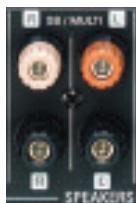
Figure 41 - Surround Back/Multiroom Speaker Outputs
If you do not require a full 7.1-channel system in your main listening area, and you prefer not to purchase an external amplifier to power a pair of remote speakers, you may reassign the AVR 347's surround back amplifier channels to power the speakers. Your main system will be limited to 5.1 channels, which affects your ability to enjoy the many DVDs and other programs recorded in 6.1 and 7.1 channels.
- Connect an external amplifier to the Surround Back/Multiroom Preamp Outputs. See Figure 42.
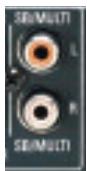
Figure 42 - Surround Back/Multiroom Preamp Outputs
This method may be used when it is more important to distribute audio to additional rooms than to have a full 7.1-channel system in the main listening area, as it is still necessary to assign the surround back amplifier channels to the remote zone, limiting the main system to 5.1 channels. This method also requires you to provide an additional component, that is, the amplifier. However, this method may be used to increase the number of remote rooms in the system when you are also using the other options for connecting a multiroom system.
- Connect an A-BUS hub or other A-BUS components to the A-BUS Port. See Figure 43.
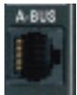
Figure 43 - A-BUS Port
Use Category 5/5e cable as described in the instructions for your A-BUS components. The A-BUS system may carry the audio signal to the remote components, while receiving IR control codes, depending on the capabilities of your A-BUS components. If you connect a hub to the AVR 347, you may distribute audio to many remote rooms. Visit our Web site at www.harmankardon.com for information on our available hubs, the ABH 4 and ABH 4000, and amplified in-wall modules, the AB 1 and AB 2.
In addition to the audio signal, you will usually wish to connect an IR control device to the AVR 347's Multiroom IR Input so that listeners in the remote room may turn the multiroom system on or off, select a source input, control the source device connected to that input and adjust the volume in the remote zone. As mentioned above, an A-BUS system does not require a separate IR control connection.
By using external multichannel amplifiers and A-BUS hubs, it's possible to construct a system that distributes audio to many rooms throughout your home.
NOTE: Only analog audio sources are available to the multiroom system.
Step Eleven - Turn On the AVR 347
Two steps are required the first time you turn on the AVR 347.
- Gently press the Master Power Switch until the word OFF is no longer visible. The Power Indicator above the two power switches should light up in amber, indicating that the AVR is in Standby mode and is ready to be turned on. See Figure 44. Normally, you may leave the Master Power Switch in the ON position, even when the receiver is not being used.

Figure 44 - Power Switches
- There are several ways in which the AVR 347 may be turned on from Standby mode.
a) Press the Standby/On Switch on the front panel. See Figure 44.
b) Press the Source Select Button on the front panel. See Figure 45.

Figure 45 - Source Select Button
c) Using the remote, press any one of these buttons: AVR, DVD/CD, TAPE/The Bridge, HDMI 1/2, VID1, VID2, VID3, VID4, XM, AM/FM or 6/8CH. See Figure 46.
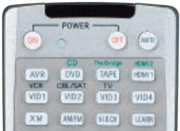
Figure 46 - AVR and Input Selectors
NOTE: Any time you press one of the Input Selectors on the remote (i.e., DVD/CD, TAPE/The Bridge, HDMI 1/HDMI 2, VID1, VID2, VID3 or VID4), the remote will switch modes so that it will only transmit the codes programmed to operate that device. In order to control the receiver, press the AVR button to return the remote to AVR mode.
Before you begin enjoying your new receiver, a few adjustments should be made to configure the AVR 347 to match your actual system.
Make sure that you have connected a video display to one of the video monitor outputs on the receiver. When you turn on your display and the AVR, you should see a blue screen. A message may appear briefly at the bottom of the screen. This message is part of the on-screen display system, and is referred to as the "semi-OSD". The semi-OSD is activated any time you send a command to the AVR, and any time the AVR detects a change in the incoming signal. Semi-OSD messages are overlaid on top of any video signal, so that you may continue to watch your program while making adjustments to the AVR.
Although it's possible to configure the AVR using only the remote and the semi-OSD messages, we recommend that you use the full-screen menu system, known as the "full OSD".
Using the On-Screen Menu System
The full-OSD system is accessed by pressing the OSD Button on the remote. See Figure 47. While the full-OSD system is in use, it isn't possible to see any video programming. In addition, an OSD ON message will appear on the front panel of the receiver to remind you to use a video display.
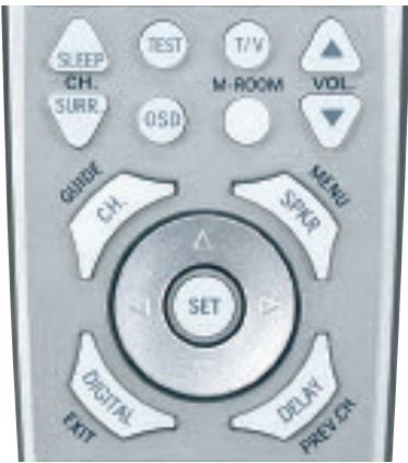
Figure 47 - Navigation Buttons
NOTE: The and Set Buttons on the front panel have no effect on the OSD system.
The OSD system consists of six main menus: Input Setup, Surround Setup, Speaker Setup, Multiroom Setup, Video Setup and System Setup. Navigation tabs for each menu appear on the left side of the screen. When you first press the OSD Button, the Input Setup menu will be visible (see Figure 48), since its tab is at the top of the screen. However, you must press the Set Button to select the Input Setup menu so that you can make any necessary adjustments. If you wish to select another menu, use the / Buttons to highlight the tab for the desired menu, and press the Set Button to select it.
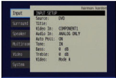
Figure 48 - OSD System
When you first select a menu, the first setting line will be highlighted (see Figure 49).
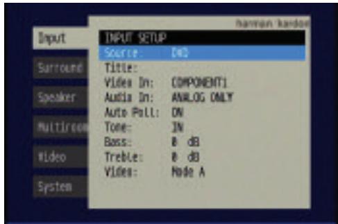
Figure 49 - Input Setup Menu
If you wish to change that setting, press the Set Button. Although the setting name will remain highlighted, the value will appear in blue type with arrows to the left and right, indicating that you may use the / Buttons to scroll through the available values. See Figure 50. When the desired value appears, press the Set Button to select it.
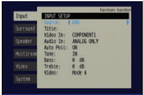
Figure 50 - Changing a Setting
Use the / Buttons to navigate to other settings within the menu. When you have finished making all adjustments in that menu, press the Button to return to the navigation tabs, and then use the / Buttons to select the tab for another menu.
We recommend that most users follow the instructions in this INITIAL SETUP section to configure a basic home theater system. You may return to these menus at any time to make additional adjustments. Thanks to the EzSet/EQ system, most of the menu adjustments may be saved until you have become more familiar with the AVR, and are therefore described in the Advanced Functions section.
The Initial Setup section requires that you complete all of the steps in the Installation section that apply to your receiver. You should have connected all of your loudspeakers and a video display, as well as your source devices. You should be able to turn on the receiver and view a blue screen on your video display. If necessary, reread the Installation Section before continuing.
Configure the AVR 347 Using EzSet/EQ
One of the most important and perhaps often overlooked aspects of setting up a home theater system is to calibrate the receiver to match the loudspeakers, which enables the AVR to perform at its best.
Until recently, most receivers required the user to perform the calibration and configuration manually, a somewhat tedious process that called for a good ear or the purchase of an SPL (sound-pressure level) meter. Although you may configure the AVR 347 manually, as described in the Advanced Features section, we recommend that most users take advantage of our signature EzSet/EQ system.
Before beginning, eliminate extraneous background noise that might affect the results, such as noisy air conditioning. Try to avoid making any loud noises while running EzSet/EQ.
IMPORTANT SAFETY NOTE: During the EzSet/EQ procedure, a series of very loud test tones will be played through all of the speakers. Avoid sitting or standing close to any one speaker during the procedure. If you are particularly sensitive to loud noises, you may wish to leave the room and have someone else run EzSet/EQ.
Step One - Place the included EzSet/EQ microphone in the listening position, or in the center of the room, at about the same height as the listeners' ears. The microphone features a threaded insert on the bottom so that it can be mounted on a camera tripod for stability.
Step Two - Plug the EzSet/EQ microphone into the Headphone. Jack/EzSet Microphone Input Jack on the front of the receiver. See Figure 51.

Figure 51 - Plug EzSet/EQ microphone into receiver.
Step Three – Make sure that the AVR 347 and the video display are turned on. Press the OSD Button to display the Menu System. See Figure 48. Use the / Buttons to move the cursor to the Speaker Setup tab, and then press the Set Button to select the Speaker Setup menu. See Figure 52.
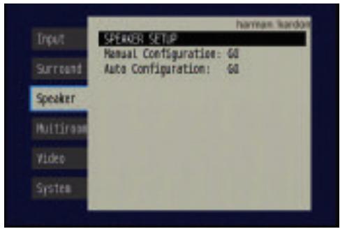
Figure 52 - Speaker Setup Menu Screen
Select the "Auto Configuration" setting, and the screen shown in Figure 53 will appear to direct you to plug the EzSet/EQ microphone into the Headphone Jack.
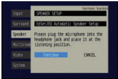
Figure 53 - EzSet/EQ Screen
Step Four - After you select "Continue", the screen shown in Figure 54 will appear. Although the AVR 347 may be used with up to eight speakers, you may have elected not to install surround back speakers at this time, or you may have decided to use the surround back speaker channels to power speakers in the remote room of a multiroom system. This screen directs you to program EzSet/EQ for a 5.1- or 7.1-channel configuration. Select the setting that reflects the number of speakers installed in your system, and EzSet/EQ will do the rest automatically!
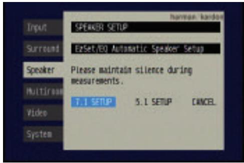
Figure 54 - EzSet/EQ: Number of Speakers
NOTE: If you are using fewer than five main speakers in your system, then it will not be possible to configure your speakers using EzSet/EQ, and you will need to select Manual Configuration as described in the Advanced Functions section. If you have selected a 6.1-channel configuration, using only a single surround back speaker, it is possible to use a combination of EzSet/EQ automatic configuration for 5.1 speakers, connect the single
surround back speaker to the left Surround Back Speaker Output, and then configure the surround back speaker manually, as described in the Advanced Functions section. However, we do not recommend the 6.1-channel configuration.
If you have forgotten to plug in the EzSet/EQ microphone, the warning screen shown in Figure 55 will appear as a reminder.
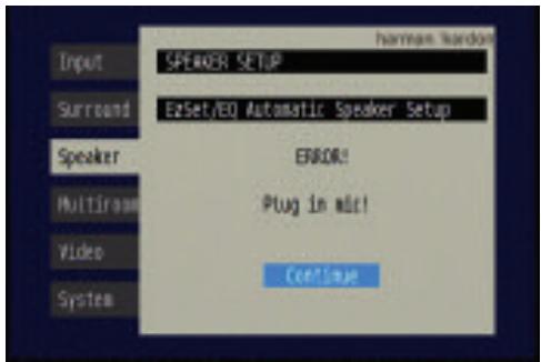
Figure 55 - EzSet/EQ: Warning to Plug in Microphone
NOTE: As shown in Figures 53, 54 and 56-59, while EzSet/EQ is in progress a Cancel setting is highlighted. You may interrupt EzSet/EQ at any time by simply pressing the Set Button.
What EzSet/EQ Does
EzSet/EQ will send test signals to the various speakers and perform the measurements described in this section, adjusting the AVR 347's settings to match EzSet/EQ's internal references.
Set Master Volume Level: EzSet/EQ sends test tones to the front speakers and adjusts the system's volume level to enable it to take the remaining measurements correctly. EzSet/EQ uses the left front speaker to set the master volume level, and then it proceeds directly to measuring the speaker output levels.
Speaker Level: During this test, EzSet/EQ ensures that all speakers sound equally loud at the listening position. During a surround sound presentation it is common for the surround channels to sound less prominent, or not to be used at all at times. By setting the baseline channel levels correctly, the AVR behaves as a blank canvas for the movie director to create special effects.
A screen similar to the one shown in Figure 56 will appear, with the speaker position changing as EzSet/EQ measures the levels for each speaker. You may occasionally hear EzSet/EQ send a tone back to the front left speaker. This enables EzSet/EQ to compare the level of the speaker being measured to the reference level it set for the front left speaker.
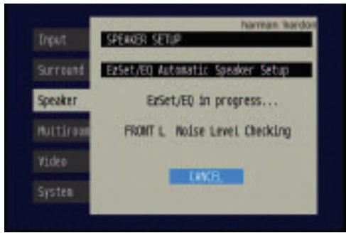
Figure 56 - EzSet/EQ: Speaker Level Test
If at any time the test tone is not heard from the speaker indicated on screen, press the Set Button to stop EzSet/EQ. Turn off the AVR using the Master Power Switch and check your speaker connections. Make sure all wires are connected to the correct speakers and Speaker Outputs on the AVR, and that you have observed the correct polarity (+ terminals connected to + terminals, and - terminals connected to - terminals).
NOTE: EzSet/EQ can detect only the presence of a speaker, not its location within the room. If your speakers are not placed reasonably close to the positions shown in the Speaker Placement Section on page 23, EzSet/EQ may not be able to perform this test correctly.
If EzSet/EQ detects only one speaker in a pair (e.g., surround back left but no surround back right or no main speakers), it will generate an error and stop. If that happens, check that you have placed your speakers in their correct locations, and that you have wired each speaker to its correct set of speaker terminals.
Speaker Distance: During this test, EzSet/EQ measures the distance from each speaker to the listening position. If the speakers are placed at different distances from the listener, the sound from speakers placed closer needs to be delayed so that it reaches the listener at the same time as the sounds from the other speakers. This preserves the clarity and directionality of surround sound presentations. During the Speaker Distance test a screen similar to the one shown in Figure 57 will appear. The speaker position will change as EzSet/EQ measures the distance for each speaker.
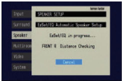
Figure 57 - EzSet/EQ: Speaker Distance Test
NOTE: The AVR 347 is also capable of setting a different type of delay, called A/V Sync Delay. A/V Sync Delay is used to compensate for lip sync problems that may occur when a video
display device or set-top box causes delays while digital video signals are processed. It simultaneously adds a delay to all speaker channels in the system. A/V Sync Delay is not set during EzSet/EQ. It may be set while watching a program as follows: press the Delay Button on the remote and the first setting displayed is A/V Sync Delay. Press the Set Button to select it and then use the / Buttons to adjust it.
Speaker Size: This test checks the low-frequency range capabilities of each of your speakers to ensure that low-frequency sounds are not sent to speakers unable to reproduce them efficiently. Each of the main speakers in your system will be assigned a value of Large or Small, depending solely on how it handles low frequencies. During the Speaker Size test a screen similar to the one shown in Figure 58 will appear, with the speaker position changing as each speaker is measured.
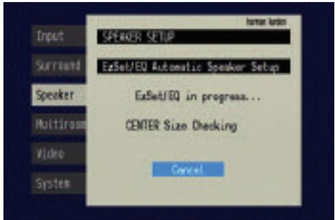
Figure 58 - EzSet/EQ: Speaker Size/Crossover Test
At the same time the overall size of the speaker's frequency range is measured, the AVR will measure the crossover, which is the lowest frequency each of your main speakers is capable of handling effectively, in order to set the highest frequency the subwoofer should reproduce. The system balances the need to ensure that all frequencies are reproduced for smooth transitions between the subwoofer and main speakers without losing any information, against the need to avoid overtaxing smaller satellite speakers.
NOTE: The crossover determined by EzSet/EQ is not the same as the crossover frequency specification that appears in the speaker's manual. EzSet/EQ is measuring the point at which the audio signal must be passed from the main speaker to the subwoofer. For an individual loudspeaker, the manufacturer specifies the point or points at which the audio signal is passed from one transducer within the speaker to another.
Equalization (EQ): Many factors unique to the listening room can affect the overall sound of a home theater system. For example, a room consisting of hardwood floors and large expanses of glass can sound livelier, with added reverberation, while a carpeted room fitted with draperies can dampen sound waves. In addition, the shape of the room can affect frequency response. If a room has a small alcove near a doorway, for example, you may notice a difference in bass response depending on whether you are standing opposite the alcove or to one side of it.
EzSet/EQ is capable of measuring the impact room characteristics and speaker placement have on each speaker's performance, and of making adjustments to low-frequency response to compensate. While EzSet/EQ
is making these adjustments a screen similar to the one shown in Figure 59 will appear. You may hear EzSet/EQ repeat tones from various speakers a number of times as it performs the equalization.
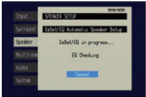
Figure 59 - EzSet/EQ: Equalization
When EzSet/EQ has finished running all of these tests, a screen similar to the one in Figure 60 will appear. You may press the Set Button, and the Speaker Setup screen shown in Figure 52 will appear. Select "Manual Configuration" to view the settings resulting from EzSet/EQ. The manual Speaker Setup screens are explained in the Advanced Functions section.
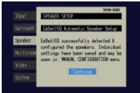
Figure 60 - EzSet/EQ: Successful Configuration
Configure Sources
In the Installation section, you physically connected various cables between your source devices and the AVR. In this section, you will assign the various audio and video inputs to their sources, ensuring that the AVR uses the correct connections each time you select a source.
Press the OSD Button to view the menu system. The Input Setup menu tab will be highlighted. Press the Set Button to select it, and the screen shown in Figure 61 will appear.
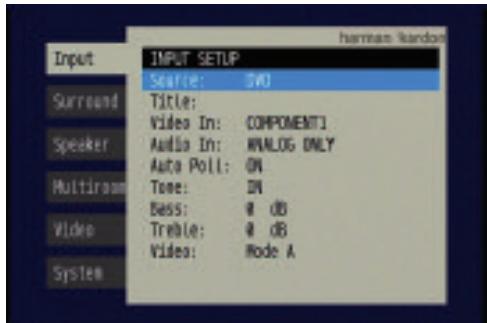
Figure 61 - Input Setup Menu
The first line indicates that the receiver is currently set to the DVD source.
Press the Set Button, and then use the to view the next source. The sources will be selected in the following order: Video 1, Video 2, Video 3, Video 4, HDMI 1, HDMI 2, 6CH Direct, 8CH Direct, DMP/ The Bridge, Tape, CD, TUNER and XM. Pressing the Button selects the sources in the reverse order.
For each of these sources, you may adjust the following settings. At a minimum, you should make sure that sources connected to any of the component video or digital audio inputs have the correct settings. Other settings are optional, and you may adjust them at a later time when you have more experience with the AVR. Refer to the Table A4 worksheet in the appendix that you filled out during installation as you assign inputs to each source.
TITLE: You may change the display name for any source. Not only does this enable you to customize your system; it helps you to select the correct source device even when you have forgotten which physical connections were used.
Move the cursor down to the TITLE line and press the Set Button. The screen shown in Figure 62 will appear.
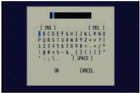
Figure 62 - Retitling a Source Input
Use the Navigation Buttons to highlight the desired letter (or other character), and press the Set Button to add it to the new title, which will be displayed in the bar at the top of the screen. You may use the Navigation Buttons, or select the left or right arrow and press the Set Button, to move the cursor within the new title. To add a space either move the cursor one character to the right as described above, or highlight the SPACE indicator on screen and press the Set Button.
You may edit a title by inserting or deleting characters. To insert a new character between two existing characters, move the cursor to highlight the character to the right of the insertion point in the bar at the top of the screen. Then highlight the INS indicator on screen and press the Set Button. You may now select a character to insert in the new space. Delete a character by moving the cursor to highlight the unwanted character in the bar at the top of the screen. Then highlight the DEL indicator on screen and press the Set Button.
When you have finished entering the new title, highlight the OK indicator and press the Set Button to return to the Input Setup menu. Although the Source Input name will remain the same in the Input Setup menu, the new title will appear in the semi-OSD displays and the front-panel display as appropriate.
NOTES:
- Only upper case letters are available for titles.
- Normally both the source input and the digital (or analog) audio input selection appear on the upper line of the semi-OSD and front-panel displays. When The Bridge source is selected, its status as CONNECTED or UNPLUGGED appears in place of the audio input selection. However, when a source input is retitled, the audio input selection (or status of The Bridge) no longer appears unless you press the Digital Input Selector on the remote or front panel.
VIDEO IN: This setting reflects the video input that is assigned to the source. The default assignment for all sources is COMPOSITE except as shown in Table 5:
Table 5 - Default Video Inputs
| Source Input | Default Video Input |
| DVD | Component 1 |
| Video 1 | Component 2 |
| Video 2 | Component 3 |
| HDMI 1 | HDMI 1 |
| HDMI 2 | HDMI 2 |
We recommend that you leave the setting for the HDMI sources as is. For the other sources, change this setting to reflect use of the Component 1, 2 or 3 Video Input as appropriate. If you used the composite or S-video input for any source, make sure this setting is COMPOSITE. (There is no separate selection for S-video.)
NOTE: If your video display has an HDMI input, then you only need to connect the AVR's HDMI Output to the display. The AVR 347 transcodes analog source video signals up to 720p from composite, S-video or component video to the HDMI format, and is also capable of upscaling the signal up to 720p to match your display's capabilities. The only exception to this rule is for analog 1080i/p sources, which are not available at the HDMI Output, but 1080i signals are passed, as is, to the Component Video Outputs. If your source device is a Microsoft Xbox 360 or an older set-top box that outputs 1080i or higher video via component video outputs, then set the source to output 720p video, or connect the AVR's Component Video Monitor Outputs to your video display. If your display does not have an HDMI input, but does have component video inputs, you only need to connect the AVR's Component Video Monitor Outputs to the display. The AVR 347 transcodes composite and S-video signals to the component video format. Similarly, if your display's best-quality video input is S-video, you do not need to connect the Composite Video Monitor Output to the display; any composite video source signals will be converted to S-video format, and S-video signals may be converted to composite video format if your video display is not equipped with an S-video input.
AUDIO IN: By default, the analog audio inputs are assigned at the factory to all sources, with the following exceptions:
Table 6 - Default Digital Audio Assignments
| Source Input | Default Digital Audio Input |
| DVD | Coax 1 |
| Video 2 | Optical 1 |
| HDMI 1 | HDMI 1 |
| HDMI 2 | HDMI 2 |
If you used a digital audio connection for another source, change this setting to assign the correct digital audio input to the source, even if you also connected the analog audio outputs of the source to the receiver.
AUTO POLL: The Auto Poll feature is used when both an analog audio and digital audio connection have been made for one source device. If for some reason no digital signal is available, the AVR 347 will switch to the analog inputs for the source. This situation can occur with some cable or satellite television broadcasts, where some channels are broadcast with digital audio and others with analog audio.
For some sources, the Auto Poll feature is unnecessary and may be undesirable. For example, if your DVD player is stopped, you may not want to use the analog audio signal or you may have decided not to connect analog audio. Move the cursor to this line, press the Set Button, and press the / Buttons until OFF appears, disabling the Auto Poll feature. With Auto Poll turned off, the receiver will only check for a signal at the audio input assigned to the source.
NOTE: Since The Bridge is connected to the AVR using a dedicated audio connection, it isn't possible to select a different audio input for this source. The AM/FM/XM tuner and 6-/8-Channel Inputs also use dedicated audio inputs, and it isn't possible to select a digital audio input for these sources.
The next three lines in the Input Setup menu activate the tone controls, and may be skipped at this time. We recommend leaving the tone controls at their factory defaults for most listening, in order to enjoy the sound mix created by your favorite movie and music artists. However, if your room or speakers have unusual characteristics, or simply as a matter of personal preference, see the Tone Controls section on page 40 for more information.
VIDEO MODE: This setting is used only with a fully analog video path (composite, S-video or component video). It has no effect on HDMI sources and video displays. Due to the design of some analog video displays and the nature of the video standard, there may be timing issues with the AVR. If you observe some minor video instability when using the AVR's analog video outputs, try changing the Video Mode setting to Mode B. If you continue to observe problems, connect your source device's video output directly to the video display, or consider upgrading to an HDMI-capable display.
You are now ready to begin enjoying your new receiver!
Now that you have installed your system components and completed at least a basic configuration of your receiver, you are ready to begin enjoying your home theater system.
Turning On the AVR 347
Gently press the Master Power Switch until the word OFF is no longer visible. The Power Indicator above the two power switches should light up in amber. This indicates that the AVR is in Standby mode and is ready to be turned on. Normally, you may leave the Master Power Switch in the ON position, even when the receiver is not being used. See Figure 63.

Figure 63 - Power Switches
There are several ways in which the AVR 347 may be turned on:
a) Press the Standby/On Switch on the front panel. See Figure 63.
b) Press the Source Select Button on the front panel. See Figure 64.
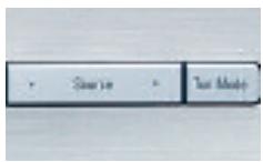
Figure 64 - Source Select Button
c) Using the remote, press any one of these buttons: AVR, DVD/CD, TAPE/The Bridge, HDMI 1/HDMI 2, VID1, VID2, VID3, VID4, XM, AM/FM, 6/8CH. See Figure 65.
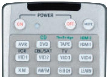
Figure 65 - AVR and Input Selectors
NOTE: Any time you press one of the remote's Input Selectors (i.e., DVD/CD, TAPE/The Bridge, XM, VID1, VID2, VID3, VID4 or HDMI 1/HDMI 2), the remote will switch modes so that it will only operate that device. To control the receiver, press the AVR Button to return the remote to AVR mode.
To turn the receiver off, press either the Standby/On Switch on the front panel, or press the AVR Button and the OFF Button on the remote. Unless the receiver will not be used for an extended period of time (for example, if you will be on vacation), it is not necessary to turn off the Master Power Switch. When the Master Power Switch is turned off, any
settings you have programmed, including system configuration and preset radio stations, will be preserved for up to four weeks.
Sleep Timer
You may program the AVR to play for up to 90 minutes and then turn off automatically using the sleep timer.
Press the Sleep Button on the remote, and the time until turn-off will be displayed. See Figure 66. Each additional press of the Sleep Button will reduce the time until turn-off by 10 minutes, until the OFF setting is reached, which disables the sleep timer.
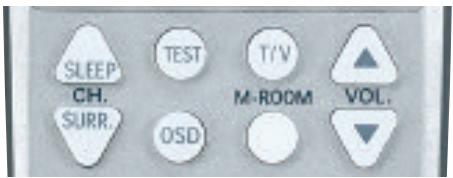
Figure 66 - Sleep Button
When the sleep timer has been set, the front-panel display will automatically dim to half-brightness. If you press any button on the remote or front panel, the display will return to full-brightness. The display will dim again several seconds after your last command.
If you press the Sleep Button after the timer has been set, the remaining time until turn-off will be displayed. You may press the Sleep Button to change the time until turn-off. Pressing and holding the Sleep Button will disable the sleep timer, and the SLEEP OFF message will appear.
Volume Control
The volume may be adjusted either by turning the knob on the front panel (clockwise to increase volume or counterclockwise to decrease volume), or by pressing the Volume Control Buttons on the remote. See Figure 67. The volume is displayed as a negative number of decibels (dB) below the 0dB reference point, and may be changed in 0.5dB increments.
Unlike the volume controls on some other products, 0dB is the maximum volume for the AVR 347. Although it's physically possible to turn the volume to a higher level, doing so may damage your hearing and your speakers. For certain more dynamic audio materials, even 0dB may be too high, allowing for damage to equipment.
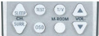

Figure 67 - Volume Controls
The AVR 347 is designed to reproduce audio with a minimum amount of distortion, which may lead you to think that your hearing and the equipment can handle higher volumes. We urge caution with regard to volume levels.
Mute Function
To temporarily mute all speakers and the headphones, press the Mute Button on the remote. See Figure 68. Any recording in progress will not be affected. The MUTE message will flash in the display as a reminder. To restore normal audio, either press the Mute Button again, or adjust the volume. Turning off the AVR will also end muting.

Figure 68 - Mute Button
Tone Controls
You may boost or cut either the treble or the bass frequencies by up to 10dB.
Using the front-panel controls or the remote, press the Tone Mode Button once. See Figure 69. This will indicate whether the tone controls are in or out of the circuitry. If you wish to return the tone controls to 0, or "flat" response, press the Buttons (▲/▼ on the remote) until the TONE OUT message appears, which preserves any changes you have made to the bass or treble settings for later use. To reactivate your changes, the tone control must again be set to TONE IN.
With the TONE IN message displayed, press the Tone Mode Button repeatedly to access TREBLE MODE and BASS MODE. Use the / Buttons (▲/▼ on the remote) to change the treble or bass settings, as desired. The display will return to normal a few seconds after your last command.
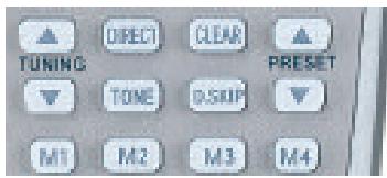
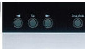
Figure 69 - Tone Button
You may alternatively adjust the tone controls using the full-OSD menu system. Press the OSD Button on the remote to view the Menu System. The Input Setup tab will be highlighted. Press the Set Button to activate the Input Setup menu. If you wish to make any changes to the TONE, BASS or TREBLE settings, use the / keys on the remote to move the cursor to the line you wish to change and press the Set Button. Once you have changed the setting using the / Buttons, press the Set Button to enter the new setting. When you have finished, either wait until the display times out and disappears, press the OSD Button to clear the display, or move the cursor to the menu tabs on the left side of the screen, if you wish to make other changes using the menu system.
NOTE: The AVR 347 does not have a conventional balance control. The EzSet/EQ process compensates for any characteristics of your room or speakers, and we recommend that you leave the settings as they are after EzSet/EQ has been run. However, you may manually adjust the levels of the left and right channels – decreasing one and increasing the other by the same amount – using the Channel Adjust submenu, as described in the Advanced Functions section. This achieves the same effect as a balance control.
Headphones
Plug the 1/4" plug on a pair of headphones into the headphone jack on the front of the receiver for private listening. See Figure 70. The first time you use the headphones, the DOLBY H:BP message will be displayed, indicating that Dolby Headphone surround processing is in the bypass mode, which delivers a conventional 2-channel signal to the headphones.
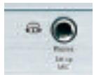
Figure 70 - Headphone Jack
Press the Surround Select Button on the front panel, or the Dolby Button on the remote, to switch to Dolby Headphone virtual surround processing, indicated by the DOLBY H:DH message. Dolby Headphone delivers an enhanced sound field that emulates a 5.1-channel speaker system. No other surround modes are available for the headphones.
Source Selection
Press the front-panel Source Select Button to scroll through the sources. The left side of the button scrolls down the list that appears in the display; the right side scrolls upward. For direct access to the tuner, press the Tuner Band Button, which switches to the last-used band and frequency. See Figure 71.

Figure 71 - Source Select and Tuner Band Buttons
NOTE: The Bridge/DMP, HDMI 1 and HDMI 2 sources have no icon in the Source Indicators display. When selected, the appropriate indication will appear in the Message Display's upper line. One of two messages will scroll on the right side to indicate whether The Bridge is unplugged or connected. If you have retitled this source, then only the new name will appear in the upper line.
For direct access to any source, press its Input Selector on the remote (see Figure 65). Since the AVR 347 allows for more source input devices than the remote has buttons for, some sources are required to share buttons. These are the DVD and CD sources, the Tape and The Bridge sources, and the HDMI 1 and HDMI 2 sources. The first press
of any of these three Input Selectors will select the source whose name appears on the button (i.e., DVD, Tape or HDMI 1), as indicated by the button lighting up in red. Press that Input Selector again quickly to select the source whose name appears above the button (i.e., CD, The Bridge or HDMI 2), and the selector will light in green to indicate that you have selected the source whose name is printed above the button.
The AVR 347 will switch to the audio and video inputs assigned to the source. If you selected a surround mode for the source, the AVR 347 will switch to that mode.
The source name will appear in the upper line of the front-panel display. If you retitled the source, only the new title will appear. Otherwise, the audio input assigned to the source (analog or one of the digital audio inputs) will also appear. The surround mode will be displayed on the lower line. The same information will also appear on screen in the semi-OSD, unless you have set the semi-OSD to OFF in the System Setup menu, as described in the Advanced Functions section.
Audio Input Selection
The AVR 347 is programmed at the factory to use the analog audio inputs for each source (except for the DVD, Video 2, HDMI 1 and HDMI 2 sources; see Table 4). To assign a digital audio input to a source (if you have not done so using the Input Setup menu during Initial Setup), press the Digital Button on the remote or front panel. The current audio input selection will flash in the display, and you may press the / (or / on the front panel) Buttons to scroll through the audio inputs. When the desired input appears, press the Set Button to select it. See Figure 72.
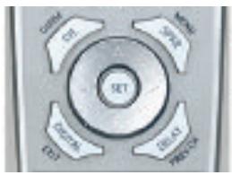
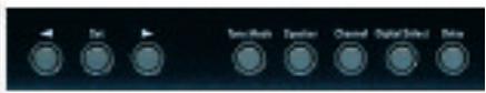
Figure 72 - Digital Input Selection
If the Auto Poll feature is ON in the Input Setup menu, and if a digital audio input has been assigned to the source, the AVR 347 will first check the digital audio input for a signal. If a signal is present, the AVR 347 will select the digital audio input. If no signal is present, the AVR 347 will switch to the analog audio inputs for the source.
Video Input Selection
When a source is selected, the AVR 347 switches to a video input as follows:
The Video IN line of the Input Setup menu indicates which of the video inputs on the AVR 347 is assigned to each source. As shown in Table 5, by default the Component Video 1 input is assigned to the DVD source, the Component Video 2 input is assigned to the Video 1 source, and the Component Video 3 input is assigned to the Video 2 source. The two HDMI inputs obtain the video signal from their own inputs, and may not be reassigned to another video input.
If your iPod is capable of playing still images and videos, it may be used as a video source. However, you may reassign the video input for The Bridge to another device for viewing while listening to audio files stored on the iPod.
All other sources default to the COMPOSITE setting, meaning that they may only be used with their composite or S-video inputs. The AVR 347 will transcode the incoming composite or S-video signal and make it available using the HDMI or component video monitor outputs, enabling a single-cable connection to your television.
NOTES:
- Due to copy-protection restrictions, there is no output at the Component Video Monitor Outputs for copy-protected sources.
- High-resolution 1080i and 1080p video signals are not available at the HDMI Output, but 1080i signals are passed through, as is, to the Component Video Monitor Outputs. If your source outputs analog high-resolution video, either use the Component Video Outputs, change the output resolution of your source device to 720p, or connect your source's component video outputs directly to your video display.
- Due to the design of some video displays, analog 480p or 720p component video source signals may produce artifacts when used with the AVR's analog video outputs (composite, S-video or component video). If this occurs, try changing the Video Mode setting in the INPUT SETUP menu, or connecting the source device's video output directly to your video display. However, for best results, we recommend you consider upgrading to an HDMI-capable video display.
- The AVR 347 cannot convert 1080i or 1080p analog video signals to the HDMI format, but passes 1080i signals to the Component Video Outputs (affecting users of Microsoft Xbox 360 systems and some older set-top boxes). If your digital cable television set-top box outputs 1080i or higher video via component video outputs and is not equipped with an HDMI output, contact your cable operator for a replacement. For Xbox 360 or satellite receivers with no HDMI output, change the settings on your source device so that it outputs only 720p video through its component video outputs, which the AVR can convert to the HDMI format, or connect the AVR's Component Video Outputs to the TV. Although you could connect the source device's component video outputs directly to your video display, you would then have to select the correct video input on the display to match the AVR's input.
The component video inputs may be reassigned to other source inputs as needed, depending on the physical connections you made during the Installation procedure.
If a signal is present at the component video input assigned to that source, it will be selected.
If no signal is present at the component video input, then the S-video or composite video input for the source will be selected. It is not possible to reassign the S-video or composite video inputs to other sources.
For audio-only sources, such as the tuner or CD inputs, when no component video signal is present, the last-used video source will be selected.
6-/8-Channel Direct Inputs
If you wish to hear audio through the 6-/8-Channel Direct Inputs together with video, then connect your multichannel player to the Component Video 1 Inputs, and connect the player's 6- or 8-channel analog audio outputs to the 6-/8-Channel Inputs on the AVR. Assign the component video inputs you selected to the 6-/8-Channel Input source. The AVR will automatically select the correct component video and audio inputs when you select this source.
If you need to use composite or S-video for your multichannel player, e.g., if your video display does not have component video inputs, then connect the device to the video inputs for another source. Since the AVR automatically selects the last-used video inputs for audio sources, first select the source you connected the video cables to, and then the 6-/8-Channel Inputs for the audio.
Example 1: You would like to connect a DVD-Audio player to the AVR 347. You plan on playing a variety of discs using this player, including conventional DVDs and even CDs, as well as multichannel discs. When playing DVDs and CDs, it is preferable to use a digital audio connection to obtain the best sound quality and the benefit of any digital surround formats contained on the DVD. However, when playing DVD-Audio discs, you will need to use the 6-/8-channel analog audio connections. In addition, some of these discs contain video materials. The player does not have an HDMI output.
We recommend that you connect this player as follows:
a) Connect the player's coaxial digital audio output to the Coaxial 1 input on the AVR. This input is assigned by default to the DVD source.
b) Connect the player's component video outputs to the Component Video 1 inputs on the AVR, which are assigned by default to the DVD source. If your video display doesn't have component video inputs, then connect the player's composite or S-video output to the DVD's corresponding video input.
c) Connect the player's 6-channel analog audio outputs to the AVR's 6-/8-Channel Inputs and assign the Component Video 1 inputs to this source using the Input Setup menu, as described in the Initial Setup section.
d) Program the player's remote control codes into the DVD Input Selector. Note that not all commands will necessarily be available.
When you wish to view a DVD, simply select the DVD source.
When you wish to listen to a DVD-Audio disc and view the menus and other still images on the disc, first select DVD, and then the 6-/8-Channel Inputs as the source.
Example 2: In this example, your multichannel disc player is equipped with an HDMI output, but it does not comply with HDMI version 1.1. Connect it as follows:
a) Connect the player's HDMI output to the HDMI 1 source input, and make sure to connect the AVR's HDMI Output to your video display. The player will transmit both digital audio (e.g., Dolby Digital or DTS
audio found on a DVD-Video disc) and video via the HDMI connection. It is not necessary to make a separate digital audio connection.
b) Connect the player's 6-channel analog audio outputs to the AVR's 6-/8-Channel Inputs and connect one of the player's analog video outputs to a source input on the AVR (e.g., Component Video 3 or Video 3).
c) Program the player's remote control codes into the Input Selector corresponding to the source you used for the analog video connection, e.g., Video 3.
When you wish to view a DVD, simply select the HDMI 1 source.
When you wish to play a multichannel disc, first select the analog video source, e.g., Video 3, to obtain the correct video signal, then select the 6-/8-Channel Inputs to select the audio signal.
To select the 6-/8-Channel Inputs as the source, use either the Source Selector on the front panel or press the 6/8CH Input Selector on the remote. See Figure 73.
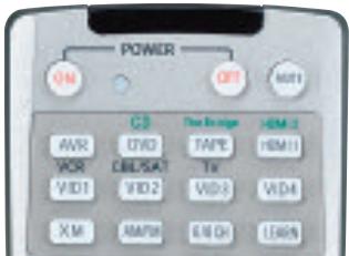

Figure 73 - 6-/8-Channel Input Selector
NOTE: The 6-/8-Channel Inputs pass the incoming signals directly to the volume control, without digitizing or processing them. Therefore, you will need to configure bass management settings (i.e., speaker size, delay and output level) on your source device so that they match the settings you programmed using EzSet/EQ, which may be viewed using the Manual Setup menu (see Advanced Functions section). Consult the owner's guide for your multichannel player for more information.
The multichannel analog audio connection is not required for DVD-Audio players compliant with HDMI version 1.1 or better, or HD-DVD and Blu-ray Disc players that decode the digital audio internally and output linear PCM signals in digital format. Consult the owner's guide for your disc player for more information.
Using the Tuner
The AVR 347's built-in tuner may be selected in one of three ways (see Figure 74):
- Press the Source Selector Button on the front panel repeatedly until the tuner is selected. The last-used band (AM or FM) will be active.
- Press the Tuner Band Button (marked AM/FM). Press this button again to switch bands. This will also enable you to select XM Radio, which is described separately in the next section.
- Press the Tuner Input Selector (marked AM/FM) on the remote. Press this button again to switch bands (AM, FM or XM).

Figure 74 - Tuner Input Selection
Radio stations may be selected in one of four ways (see Figure 75):
- If you know the frequency number, enter it directly by first pressing the Direct Button on the remote, and then using the Numeric Keys.
- After you have programmed Preset stations (see below), either enter the Preset number (1 through 30) using the remote or use the Preset Stations Buttons (front-panel or remote) to scroll through the list of presets.
- In Auto tuning mode, with each press of the Tuning Buttons (front panel or remote), the AVR 347 will scan in the chosen direction until a station with acceptable signal strength is detected. Press the Tuning Button again to stop scanning.
- In Manual tuning mode, with each press of the Tuning Buttons, the AVR 347 will tune the next frequency increment (0.1MHz for FM, or 10kHz for AM) in the selected direction. Press and hold the Tuning Button for faster scanning.
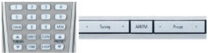
Figure 75 - Tuning a Station
Press the Tuning Mode Button (TUN-M on the remote) to switch between Auto and Manual tuning modes. See Figure 76. When an FM station has been tuned, pressing the Tuning Mode Button will switch between stereo and mono tuning, which may improve reception of weaker stations.
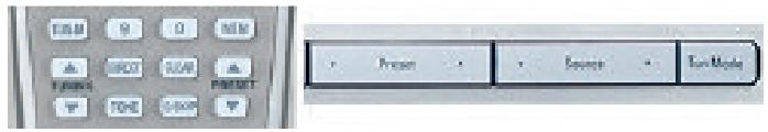
Figure 76 - Tuning Mode
To store a station in one of the 30 presets (see Figure 77):
- Tune the desired station.
- Press the Memory Button on the remote.
- Use the Numeric Keys to enter the desired preset number.
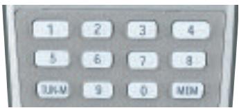
Figure 77 - Storing a Preset Station
XM Radio Operation
XM Radio is a satellite-delivered service that offers hundreds of program channels, as well as local traffic and weather information for select cities. The AVR 347 is "XM Ready," which means that it is able to receive the
XM service when an optional XM antenna module is connected and the service activated. As of this writing, the Audiovox® CNP 1000 “Connect and Play” module for home audio use and the XM Mini-Tuner and Home Dock (Models CNP-2000 and CNP-2000H) are compatible with the AVR 347. Additional modules may become available in the future. Modules produced for automotive, or “mobile,” use are not compatible with the AVR 347.
NOTE: To listen to XM Radio using the AVR 347, you will need to purchase an XM antenna module and subscription, and you will need to activate your module. (Note that XM service is not available in Alaska or Hawaii.) Visit the XM Radio Web site at www.xmradio.com for more information.
Plug the module into the XM Antenna Jack on the rear of the AVR 347. Place the antenna module so that it has a clear view through a south-facing window in order to obtain reception from the XM satellite.
Select XM Radio as the source in one of the following three ways (see Figure 78):
- Press the Source Selector button on the front panel repeatedly until XM Radio is selected. XM will only appear in the Message Display.
- Press the Tuner Band Button (front-panel or remote) repeatedly until XM Radio is selected.
- Press the XM Radio Input Selector on the remote.
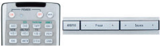
Figure 78 - XM Radio Source Selection
You should be able to tune in Channel 1, the Preview Channel, to confirm that your equipment is ready for activation. There are three ways to tune an XM Radio channel (see Figure 75):
- Enter the channel number directly using the Numeric Keys on the remote. It is not necessary to press the Direct Button first.
- Press the Tuning Buttons on the front panel or remote to scan through the channels. Auto tuning mode is not available.
- The AVR 347 is capable of storing up to 40 XM Radio preset channels. The presets are divided into five banks, denoted by the letters A through E, with eight numeric presets per bank. After you have programmed preset stations (see below), you may select one by pressing the Set Button repeatedly until PRESET SEARCH appears, then using the / Buttons to change the bank (A through E). Use the Preset Buttons to scan through the eight numeric positions within a bank.
When you are able to hear Channel 1, you are ready to activate your module. If you don't hear Channel 1, make sure the module's plug is firmly seated in the XM Antenna jack, and that the module is near a south-facing window. Try unfolding the module and rotating it to obtain reception. You may need to purchase an extension cable, available on the XM Radio site, to ensure that the module is near the window.
Tune to Channel 0 for a display of your antenna module's Radio ID number, required for activation.
The current channel number and preset location will appear in the upper line of the Message Display, and the channel's name will appear in the lower line. Three signal-strength bars will appear to the right of the channel number and preset location. Press the Tuning Mode Button repeatedly to display the category, current artist or song title.
For traffic and weather channels, the current city's name will appear instead of the channel name, and pressing the Tuning Mode Button repeatedly will display the local weather and temperature.
Press the Set Button to search all channels. Press it again to search by category, using the / Buttons to change the category and then pressing the Set Button to tune the first available channel in the new category. Press the Set Button again to change the preset bank, using the / Buttons to change the bank letter. Press the Set Button again to return to the all-channel search.
To store a channel in one of the 40 preset locations:
- Press the Set Button repeatedly until PRESET SEARCH appears, then use the / Buttons until the desired bank of presets (A through E) appears in the upper line of the message display.
- Press the Memory Button, and a line will appear next to the preset bank letter.
- Use the Numeric Keys to enter the preset location (1 through 8) you wish to store the channel in.
Recording
Two-channel analog and digital audio signals, as well as composite and S-video signals, are normally available at the appropriate recording outputs. Thus, to make a recording, you need only make sure to connect your audio or video recorder to the appropriate output jacks, as described in the Installation section, insert blank media and make sure the recorder is turned on and recording while the source is playing.
NOTES:
- Analog audio signals are not converted to digital form, and digital audio signals are not converted to analog audio form. However, you may record a coaxial or optical digital audio source using either type of digital audio output.
- Only PCM digital audio signals are available for recording. Proprietary formats such as Dolby Digital and DTS may not be recorded using the digital audio connections, although if the source is connected to the AVR using the analog audio connections, an analog recording may be made.
- Component video and HDMI sources are not available for recording.
- Please make certain that you are aware of any copyright restrictions on any material you record. Unauthorized duplication of copyrighted materials is prohibited by federal law.
Using The Bridge
The Bridge is an optional dock that may be used with a compatible iPod (not included). When The Bridge is connected to its proprietary input on the AVR 347 and the iPod is docked, you may play the audio, video and still-image materials on your iPod through your high-quality audio/video system, operate the iPod using the AVR remote or the AVR's front-panel controls, view navigation messages on the AVR's front panel or a connected video display, and charge the iPod.
Either press the front-panel Source Selector repeatedly until the message "DMP/The Bridge is CONNECTED" scrolls across the front panel and appears in the semi-OSD display, or press the DMP Button on the remote to select The Bridge as the input source.
When an iPod is docked in The Bridge, the screen shown in Figure 79 will appear on a video display connected to the AVR. Navigate The Bridge's screens by using the / Buttons to highlight a line and pressing the Set Button to select the line. The Button scrolls down, and the Button scrolls up. Press the Menu Button to return to the previous level of The Bridge's menu system. Remember to set the remote in The Bridge device mode by pressing the Tape/The Bridge Button. If it lights in red, press it again quickly so that it lights in green, indicating it is in The Bridge mode.
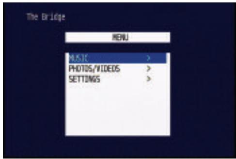
Figure 79 - The Bridge: Main Menu Screen
MUSIC: This line allows you to navigate the audio materials stored on your iPod.
PHOTOS/VIDEOS: Selecting this item allows you to play still images or videos stored on the iPod. The screen shown in Figure 80 will appear, directing you to operate the iPod's own controls directly to play images and videos. You may use the AVR 347 remote instead of the iPod's controls to navigate it. Visual materials will be displayed on a video display connected to the AVR.
NOTE: After selecting video/photo viewing, the AVR may remain in iPod Manual Mode, even after undocking the iPod or switching to another source input and back again. To return to normal operation, with the AVR remote in The Bridge mode, press and hold the Menu Button.
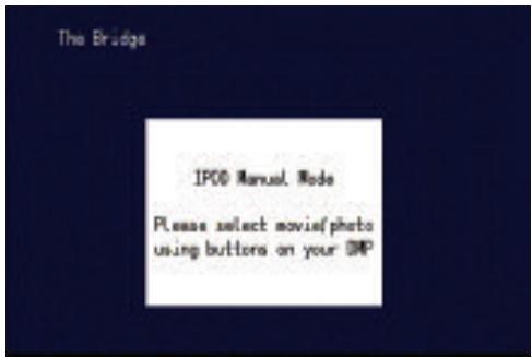
Figure 80 - The Bridge: Playing Images and Videos
SETTINGS: This line accesses the Settings menu, shown in Figure 81. The items in this menu enable you to use the Shuffle and Repeat functions on the iPod. You may also set the Resume function, which resumes play of a selection from the point at which it was stopped,
NOTE: iTunes allows you to set certain selections to always or never remember playback position, or to be skipped in Shuffle mode. The AVR 347's settings cannot override these iTunes settings.

Figure 81 - The Bridge: Settings Menu Screen
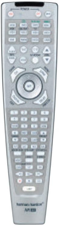
Figure 82 - Using The Bridge (Remote)
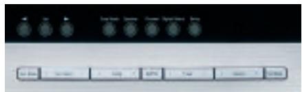
Figure 83 - Using The Bridge (Front Panel)
Table 7 summarizes the controls available when The Bridge is in use. See also Figures 82 and 83.
Table 7 - Using The Bridge
| iPod Function | Remote Control Key | Front-Panel Button |
| Play | Play (▶) | Tuner Mode |
| Pause | Pause (II) | Tuner Mode |
| Menu | Menu (Spkr) | Tuner Band (AM/FM) |
| Select | Set | Set |
| Scroll Forward | Left Arrow (▲) | Preset Down |
| Scroll Reverse | Right Arrow (▲) | Preset Up |
| Forward Search/Next Track | Forward/Next (▲▶) | Tuning Up |
| Reverse Search/Previous Track | Reverse/Previous (▲▶) | Tuning Down |
NOTES:
- The Play and Pause functions are not available unless content has been selected for playback by navigating the menu system.
- For the Search function, press and hold the indicated button. Pressing the Previous Track Button once skips to the beginning of the current track. Press the Previous Track Button twice to skip to the beginning of the previous track.
While a selection is playing, the song title, artist and album name, if available on the iPod, will scroll across the upper line in the front-panel Message Display. The lower line will display the elapsed time of the track on the left, the play mode icon, and the time remaining on the right.
In addition, if a video display is connected to the AVR 347, a screen will appear briefly to display information about the iPod's status and the track. The top line will display the play mode icon, with the phrase "Now Playing" appearing to the right to indicate that you are viewing the status of the current track. Below that, the AVR displays the total number of tracks in the current playlist on the right (all materials on the iPod are considered one playlist) with the number of the current track on the left. The song title, artist and album are displayed. At the bottom of the screen is a graphic bar indicating the current play position within the track, with the elapsed and remaining times appearing below the bar.
After a period of time, the screen may disappear from view. The length of time is set using the Full-OSD Time-Out setting in the System Settings menu (described in the Advanced Functions section). You may restore the Now Playing screen to view by pressing either of the / Buttons, and you may then navigate the menus as explained above.
NOTE: It is strongly recommended that you use a screen saver built into your video display to avoid possible damage from "burn-in" that may occur with plasma and many CRT displays when a still image, such as a menu screen, remains on display for an extended period of time.
NOTES ON VIDEO PLAYBACK:
- Before attempting to play videos stored on your iPod, check the Video Settings menu on the iPod and make sure that the TV Out setting is set to On. The TV Signal setting should be NTSC to match the capabilities of your video display. Set Widescreen to On or Off, depending on the aspect ratio of your video display. If your selection was playing and paused at the time you changed the TV Out setting, the iPod may require you to navigate its menu system and reselect the video for the new TV Out setting to take effect. Resuming play from the Now Playing function may not reflect the change to the TV Out setting. This is a function of the iPod, not the AVR 347.
- In Video mode, the iPod's menus will not be visible on your video display, although you may view them on the iPod's screen. You may operate the iPod using the AVR remote, as long as it is in The Bridge device mode.
- You may view the AVR's on-screen displays while The Bridge is in use, just as you would with any other video source.
- The MP4 and H.264 video formats often used for videos to be played on the iPod are intended for optimal performance on the iPod's small screen. Playback on larger displays may have different results.
Selecting a Surround Mode
Surround mode selection can be as simple or sophisticated as your individual system and tastes. Feel free to experiment with the many available surround modes on the AVR 347, and you may find a few that become your favorites for certain sources or program types. Although more detailed information on surround modes may be found in the Advanced Functions section, it is easy to select any of the modes available at a given time:
To select a surround mode using the front-panel controls, press the Surround Mode Button repeatedly until the desired group of modes is selected: Logic 7, Dolby, DTS, DSP or Stereo. Then press the Surround Select Button repeatedly to select the desired mode within the group. See Figure 84.

Figure 84 - Select a Surround Mode (Front Panel)
To select a surround mode using the remote control, locate the button dedicated to the desired group of modes: Logic 7, Dolby Sur, DTS Sur, DTS Neo:6, Surr (DSP) or Stereo. Press that button repeatedly to select the desired mode. See Figure 85.
To select a surround mode using the full-OSD menu system, press the OSD Button to display the Menu System. Use the / Buttons to highlight the Surround tab, and press the Set Button to access the
Surround Setup menu, as shown in Figure 86. With the Surround Mode highlighted, press the Set Button to change the surround mode group. Use the / Buttons to scroll through the options, and press the Set Button when the desired mode group appears. Navigate to the Mode line and follow the same procedure to select an individual mode. As explained in the Advanced Functions section, there are also some additional settings that may be made.
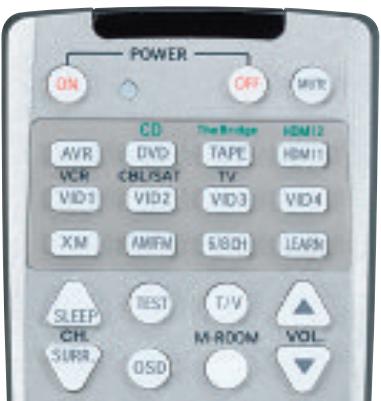
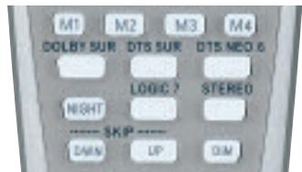
Figure 85 - Select a Surround Mode (Remote)
You are now ready to enjoy the best in home theater entertainment with your AVR 347. As you become more familiar with the receiver, you may wish to explore some of its advanced functions, which are described in the following section.
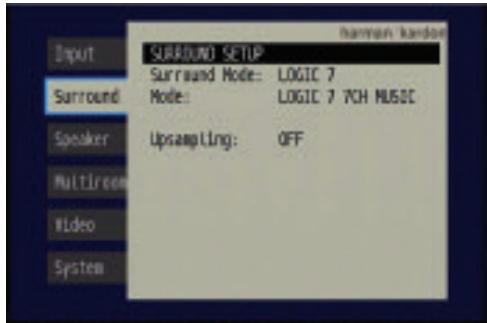
Figure 86 - Surround Setup Menu Screen
Much of the AVR 347's performance is handled automatically, with little intervention required on your part. However, the AVR 347 is a sophisticated component, and is capable of being customized to suit your particular system and your tastes. In this section we describe some of the more advanced adjustments available on the AVR 347. You may return to this section later, when you have become more familiar with your receiver.
Audio Processing and Surround Sound
Audio signals output by sources are encoded in a variety of formats that can affect not only the quality of the sound but the number of speaker channels and the surround mode. You may also manually select a different surround mode, although for certain types of audio signals, the modes available will be limited in certain ways, as described below.
Analog Audio Signals
Analog audio signals usually consist of two channels - left and right. The AVR 347 offers three basic options for playback of analog audio:
- Analog Bypass Mode: In this mode, the 2-channel signal is passed directly to the volume control, without being digitized or undergoing any processing for bass management or surround sound. The requirements for selecting analog bypass mode are:
a) The analog audio inputs for the source must be selected. If necessary, press the Digital Button on the remote and use the / Buttons to make the selection.
b) The tone controls must be disabled by setting TONE MODE to OUT. Either use the Input Setup menu in the full-OSD system to make this change, or press the Tone Mode Button on the front panel or remote and use the / Buttons (▲/▼ on the remote) until the TONE OUT message appears.
c) The Surround Off mode must be selected. The easiest way to select the Surround Off mode is to press the Stereo Button on the remote until the Surround Off icon is lit (and the DSP icon is not lit) in the front-panel display.
- DSP Surround Off Mode: The DSP Surround Off mode digitizes the incoming signal and applies the bass management settings, including speaker configuration, delay times and output levels. This mode is desirable when your front speakers are small, limited-range satellites and you are using a subwoofer. Both the DSP and Surround Off icons will be lit when this mode is active. Press the Stereo Button on the remote repeatedly to select this mode.
- Analog Surround Modes: One of the main benefits of a surround receiver such as the AVR 347 is its ability to process 2-channel audio signals to produce multichannel surround sound in a variety of modes, even when no surround sound has been encoded in the recording. Among the available modes are the Dolby Pro Logic II/IIx modes, the Dolby Virtual Speaker modes, the DTS Neo:6 modes, the Logic 7 modes, the Hall and Theater modes and the Stereo modes.
Digital Audio Signals
Digital audio signals offer the benefit of greater capacity, which allows recording artists to encode center and surround channel information directly into the signal. The result is improved sound quality and startling directionality, since each of these channels is reproduced discretely.
Alternatively, the artist will encode only two channels, but the digital signal allows for a higher sampling rate, which delivers greater detail. High-resolution recordings usually sound extraordinarily distortion-free at all frequencies, but especially at high frequencies.
Multichannel digital recordings usually are found in the 5.1-, 6.1- or 7.1-channel formats. The channels included in a 5.1-channel recording are front left, front right, center, surround left, surround right and LFE. The LFE channel is denoted as ".1" to represent the fact that it is not full-range, being limited to the low frequencies.
6.1-Channel recordings add a single surround back channel, and 7.1-channel recordings add surround back left and surround back right channels to the 5.1-channel configuration. New formats, such as Dolby TrueHD and Dolby Digital Plus, may be available in 7.1-channel configurations on the future. The AVR 347 will not be able to play native 7.1-channel programs unless the source device outputs a 5.1- or 6.1-channel version.
NOTE: In order to use the 6.1- and 7.1-channel surround modes, e.g., Logic 7.7-channel Cinema, the AVR 347 must be configured so that the Surround Back channels are enabled. See the Manual Setup section on page 53 of the Advanced Functions section for more information.
Digital formats include Dolby Digital 2.0 (two channels only), Dolby Digital 5.1, Dolby Digital EX, DTS 5.1, DTS-ES (6.1 Matrix and Discrete), DTS 96/24 and 2-channel PCM modes in 32kHz , 44.1kHz , 48kHz or 96kHz .
When a digital signal is received, the AVR 347 detects the encoding method and the number of channels. The appropriate icon will light in the front panel for Dolby Digital and DTS signals. The number of channels encoded will scroll once across the front panel display as three numbers, separated by slashes (e.g., "3/2/.1").
The first number indicates the number of front channels in the signal:
"1" represents a monophonic recording, usually an older program that has been digitally remastered or, more rarely, a modern program for which the director has chosen a special effect.
"2" indicates the presence of the left and right channels, but no center channel.
"3" indicates that all three front channels (left, right and center) are present.
The second number indicates whether any surround channels are present:
"0" indicates that no surround information is present.
"1" indicates that a matrixed surround signal is present.
"2" indicates discrete left and right surround channels.
"3" is used with DTS-ES bitstreams to represent the presence of the discrete surround back channel in addition to the side surround left and right channels.
The third number is used for the LFE channel:
"0" indicates no LFE channel.
.1" indicates that an LFE channel is present.
The 6.1-channel signals - Dolby Digital EX and DTS-ES Matrix and Discrete - each include a flag meant to signal the receiver to decode the surround back channel.
For Dolby Digital EX materials, the incoming bitstream will be displayed as 3/2/.1 EX-ON. For older discs, the display may show EX-OFF, but you will still be able to select the Dolby Digital EX mode manually by pressing the Dolby button on the remote repeatedly, or using the front-panel controls.
For DTS-ES materials, the incoming bitstream will be displayed as 3/3/.1 ES-ON.
Please refer to Table 8 for more information on which surround modes are available with different bitstreams.
When a PCM signal is received, the PCM message, followed by the sampling rate of the signal (32kHz, 44.1kHz, 48kHz or 96kHz), will scroll once across the front-panel display.
In addition, the Speaker/Channel Input Indicators will indicate the number of channels discretely encoded in the signal by displaying a letter inside that channel's speaker box. A line will connect the SBL and SBR boxes when a 6.1-channel signal is detected, indicating that the same signal is playing through both speakers. The letters flash when no signal is present, such as when a DVD is paused. See Figure 87.
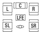
[SBL] [SBR] Figure 87 - Speaker/Channel Input Indicators
Even when only two channels - left and right - are present in the signal, the analog surround modes may be used to decode the signal into the remaining channels.
NOTE: Dolby Digital 2.0 signals may also include a Dolby Surround flag indicating DS-ON or DS-OFF, depending on whether the two-channel bitstream contains only stereo information, or a downmix of a multichannel program that can be decoded by the Dolby Pro Logic decoder in the AVR. By default, these signals are played in Dolby Pro Logic IIx Movie mode, but you may select another Dolby surround mode manually.
Surround Modes
As mentioned in the Introduction to Home Theater section, surround mode selection is dependent upon the format of the incoming audio signal, as well as personal taste. There is no harm in experimenting with all of the modes available with any given source material. Table 8 offers
a brief description of each mode the AVR 347 is capable of using, and also indicates the types of incoming signals or digital bitstreams the mode may be used with. Additional information about the Dolby and DTS modes is available on the companies' Web sites: www.dolby.com and www.dtsonline.com.
When in doubt, check the jacket of your DVD for more information on which surround modes are available on the disc. Usually nonessential sections of the disc, such as trailers, extra materials or the disc menu, are only available in Dolby Digital 2.0 (2-channel) or PCM 2-channel mode. If the main title is playing and the letters in the Speaker/Channel Input Indicators are not lit for all speaker locations, look for an audio setup section in the disc's menu. Also, make sure your DVD player's audio output is set to the original bitstream rather than just PCM. Check the DVD player's output setting by stopping play of the disc and checking the DVD player's menu system.
As indicated in Table 8, different surround modes may only be available with certain input signals or bitstream formats. For any incoming signal, only a limited number of surround modes are available. Although there is never a time when all of the AVR 347's surround modes are available, there is usually a wide variety of modes available for a given input.
There are three methods of manually selecting one of the available surround modes:
- From the front panel, press the Surround Mode Button until the desired mode group (Dolby, DTS, DSP, Stereo, Logic 7) is selected, and the last-used mode from that group will be activated. Then press the Surround Select Button repeatedly to scroll through the modes available within that group.
- Using the remote, press the button for the desired mode group:
Dolby Sur for Dolby modes
DTS Sur for DTS Digital modes
DTS Neo:6 for the DTS Neo:6 modes
Logic 7 for the Logic 7 modes
Stereo for the Stereo or Surround Off modes
Surr for the DSP Surround modes (Hall 1, Hall 2, Theater)
Press the mode button repeatedly to scroll through the modes available within that group.
- The full-OSD menu system allows access to submenus for each of the mode groups through the Surround Setup menu. See Figure 86.
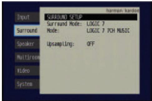
Figure 86 (repeated) - Surround Setup Menu Screen
Press the Set Button to access the Surround Setup menu, as shown in Figure 86. With the Surround Mode highlighted, press the Set Button to change the surround mode group. Use the Buttons to scroll through the options, and press the Set Button when the desired mode group appears. Navigate to the Mode line and follow the same procedure to select an individual mode. The Upsampling setting is only available for the Dolby modes. You may wait for the full-OSD screen to time out and disappear from view, or press the Button to return to the menu tabs and select another menu.
Dolby Surround Settings
Some additional settings are available for Dolby modes. Three settings are active only when the Dolby Pro Logic II or Ilx Music modes have been selected. See Figure 88.
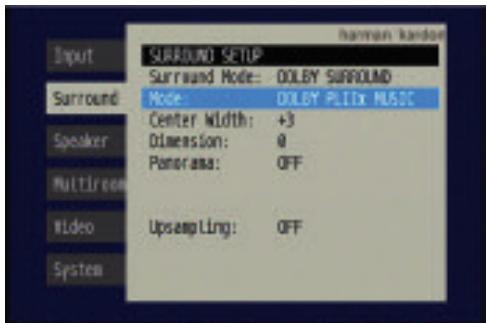
Figure 88-Dolby Settings
CENTER WIDTH: This setting affects how vocals sound through the three front speakers. A higher number (up to 7) focuses the vocal information tightly on the center channel. Lower numbers broaden the vocal soundscape across the three speakers.
DIMENSION: This setting affects the depth of the surround presentation, allowing you to "move" the sound toward the front or rear of the room. The setting of "0" is a neutral default. Setting "F-3" moves the sound mostly toward the front of the room, while setting "R-3" moves the sound mostly toward the rear.
PANorama: With the Panorama mode turned ON, some of the sound from the front speakers is moved to the surround speakers, creating an enveloping "wraparound" type of effect.
UPSAMPLING: The last line of the Surround Setup menu activates upsampling, only available with the Dolby Pro Logic II/IIx Movie, Dolby Pro Logic II/IIx Music and Dolby Pro Logic modes. Normally set to OFF, upsampling, when activated, processes digital sources at a higher resolution for improved sound quality. This feature can be useful to eliminate distortion in some low-resolution sources.
Night Mode
Night mode is available with some Dolby Digital programs, if it has been encoded in the material. It compresses the peak sound levels, maintaining the intelligibility of the dialogue and quieter passages, while reducing the loudness of special effects and louder passages to avoid disturbing others. Three levels of compression are available:
OFF: At this setting, there is no compression, as the Night mode is deactivated.
MID: A mild compression is applied.
MAX: More compression is applied.
We suggest that you experiment with the modes to find a setting that meets your needs.
The Night mode is not adjusted using the full-OSD menu system. With a Dolby Digital program encoded with Night mode playing, press the Night Button on the remote. Each press of the button will cycle through the three settings, with the selected setting being displayed on the front panel and in the semi-OSD display.
Default Modes
During initial use or after a processor reset, the AVR 347 will default to the Logic 7 7CH Music mode for all analog and PCM audio inputs. Subsequently, when a source input is selected and an analog or PCM signal is received, the AVR will switch to the last surround mode used for that source input/incoming signal combination.
Whenever a multichannel Dolby Digital or DTS signal is detected, the AVR 347 will automatically switch to that mode, unless the Default Surround Mode setting in the System Setup menu has been changed to OFF. You may observe that other surround modes are available for use with the multichannel digital bitstreams. If you would prefer the AVR 347 to use one of those alternate modes any time the same digital signal is detected, then select that mode while the multichannel bitstream is present, and then change the Default Surround Mode setting in the System Setup menu to OFF.
Table 8 provides descriptions of all surround modes available on the AVR 347, along with the incoming bitstreams or signals that the particular mode may be used with. Feel free to experiment and simply cycle through all of the available modes at any time; you cannot cause any problems for the AVR 347 by doing so.
NOTE: In order to access 6.1- and 7.1-channel modes, such as Dolby Digital EX, DTS-ES, Logic 7 (7.1 modes), DTS Neo:6 (6.1 modes), the 6-channel implementations of Hall 1, Hall 2 and Theater and 7-channel Stereo, you must enable the surround back channels as explained in the Manual Setup section. You should not enable these channels if you don't have surround back speakers in your system.
Table 8 – Surround Modes
| Surround Mode | Description | Incoming Bitstream or Signal |
| Dolby Digital | Provides up to five separate main audio channels and a dedicated low-frequency effects (LFE) channel. May be encoded for Night mode, which allows the user to apply a compression setting that maintains intelligibility of softer passages while reducing the loudness of dynamic passages to avoid disturbing others. | • Dolby Digital 1/0/.0 or .1, 2/0/.0 or .1, 3/0/.0 or .1, 2/1/.0 or .1, 2/2/.0 or .1, 3/2/.0 or .1 • Dolby Digital EX (played as 5.1) |
| Dolby Digital EX | An expansion of Dolby Digital 5.1 that adds a surround back channel which may be played through one or two surround back speakers. May be manually selected when a non-EX Dolby Digital stream is detected. | • Dolby Digital EX • Dolby Digital 2/2/.0 or .1, 3/2/.0 or .1 |
| Dolby Digital Stereo | Delivers a 2-channel downmix of Dolby Digital materials. | • Dolby Digital 1/0/.0 or .1, 2/0/.0 or .1, 3/0/.0 or .1, 2/1/.0 or .1, 2/2/.0 or .1, 3/2/.0 or .1 • Dolby Digital EX |
| Dolby Pro Logic II Mode Group | Analog decoder that derives five full-range, discrete main audio channels from matrix surround-encoded or 2-channel analog sources. Four variants are available. | See below. |
| Dolby Pro Logic II Movie | Variant of Dolby Pro Logic II that is optimized for movie and television programs. | • Dolby Digital 2.0 or 2.1 • Analog (2-channel) • Tuner • PCM (32kHz, 44.1kHz, 48kHz, 96kHz) |
| Dolby Pro Logic II Music | Variant of Dolby Pro Logic II that is optimized for music selections. Allows adjustment of sound field presentation in three dimensions: • Center Width (adjusts width of vocal soundstage) • Dimension (adjusts depth of soundstage) • Panorama (adjusts wraparound surround effect) | • Dolby Digital 2.0 or 2.1 • Analog (2-channel) • Tuner • PCM (32kHz, 44.1kHz, 48kHz, 96kHz) |
| Dolby Pro Logic II Game | Variant of Dolby Pro Logic II that emphasizes use of the surround channels and subwoofer for total immersion in the video gaming experience. | • Dolby Digital 2.0 or 2.1 • Analog (2-channel) • Tuner • PCM (32kHz, 44.1kHz, 48kHz, 96kHz) |
| Dolby Pro Logic | Original version of Dolby Pro Logic that steered a mono signal containing information below 7kHz to the surround channels. | • Dolby Digital 2.0 or 2.1 • Analog (2-channel) • Tuner • PCM (32kHz, 44.1kHz, 48kHz, 96kHz) |
| Dolby Pro Logic Ilx Mode Group | An expansion of Dolby Pro Logic II that adds a surround back channel which may be played through one or two surround back speakers. The Dolby Pro Logic Ilx modes may be selected not only with Dolby Digital bit-streams, but thanks to the AVR 347's post-processor, they may also be used with some DTS bitstreams to add a surround back channel to 5.1 modes. | |
| Dolby Pro Logic Ilx Movie | This mode is similar to Dolby Pro Logic II Movie, with an added surround back channel. In addition, it may be selected even when some types of DTS signals are present for a somewhat different presentation. | • Dolby Digital 2/0/.0 or .1, 2/2/.0 or .1, 3/2/.0 or .1, EX • DTS 2/2/.0 or .1, 3/2/.0 or .1 • DTS 96/24 • DTS-ES Matrix • DTS-ES Discrete • Analog (2-channel) • Tuner • PCM (32kHz, 44.1kHz, 48kHz, 96kHz) |
| Dolby Pro Logic IIx Music | This mode is similar to Dolby Pro Logic II Music, including the availability of center width, dimension and panorama adjustments. Dolby Pro Logic IIx Music adds a surround back channel. In addition, it may be selected even when some types of DTS signals are present. | • Dolby Digital 2/0/.0 or .1, 2/2/.0 or .1, 3/2/.0 or .1, EX • DTS 2/2/.0 or .1, 3/2/.0 or .1 • DTS 96/24 • DTS-ES Matrix • DTS-ES Discrete • Analog (2-channel) • Tuner • PCM (32kHz, 44.1kHz, 48kHz, 96kHz) |
| Dolby Pro Logic IIx Game | This mode is similar to Dolby Pro Logic II Game, with the added benefit of a surround back channel. | • Dolby Digital 2/0/.0 or .1 • Analog (2-channel) • Tuner • PCM (32kHz, 44.1kHz or 48kHz) |
| Dolby Virtual Speaker Mode Group | Simulates 5.1 channels when fewer speakers are present, or a more enveloping sound field is desired. | See below. |
| Dolby Virtual Speaker Reference | When fewer than five main speakers are present, the Reference mode virtualizes the missing speakers with accurate localization. Select from two- or three-speaker mode, depending on how many physical speakers are in your system. | • Dolby Digital (uses only two-speaker mode when signal does not contain center channel information) • Analog (2-channel) • Tuner • PCM (32kHz, 44.1kHz or 48kHz) |
| Dolby Virtual Speaker Wide | Wide mode may be used with two, three, four or five main speakers to widen the front soundstage by virtualizing the locations of the left and right speakers. | • Dolby Digital (number of channels available varies by number of channels in signal) • Analog (2-channel) • Tuner • PCM (32kHz, 44.1kHz or 48kHz) |
| DTS Digital | Using a different encoding/decoding method than Dolby Digital, it also provides up to five discrete main channels, plus an LFE channel. | • DTS 1/0/.0 or .1, 2/0/.0 or .1, 3/0/.0 or .1, 3/1/.0 or .1, 2/2/.0 or .1, 3/2/.0 or .1 • DTS-ES Matrix (played as 5.1) • DTS-ES Discrete (played as 5.1) |
| DTS-ES Matrix | DTS Extended Surround adds a single surround back channel to DTS 5.1 digital surround sound. The Matrix version includes the surround back channel information "matixed" into the left and right (side) surround channels, for compatibility with 5.1-channel systems. | • DTS-ES Matrix |
| DTS-ES Discrete | DTS-ES Discrete is another Extended Surround mode that adds a surround back channel, but this information is encoded discretely on the disc, and is not derived from information contained in the surround channels. | • DTS-ES Discrete |
| DTS Stereo | Delivers a 2-channel downmix of DTS Digital materials, or presents a matrix-encoded surround presentation. | • DTS 1/0/.0 or .1, 2/0/.0 or .1, 3/0/.0 or .1, 3/1/.0 or .1, 2/2/.0 or .1, 3/2/.0 or .1 • DTS 96/24 • DTS-ES Matrix • DTS-ES Discrete |
| DTS Neo:6 Mode Group | DTS Neo:6 analog processing is available with DTS and DTS 96/24 signals and 2-channel analog or PCM signals to create a 3-, 5- or 6-channel presentation. | See below. |
| DTS Neo:6 Cinema | Depending on the number of speakers in your system, select 3-, 5- or 6-channel modes, enhanced for movie or video presentations. | • DTS 2/2/.0 or .1, 3/2/.0 or .1 • DTS 96/24 • Analog (2-channel) • PCM (32kHz, 44.1kHz or 48kHz) |
| DTS Neo:6 Music | Available only in 5- and 6-channel modes, creates a surround presentation suitable for music recordings. | • DTS 2/2/.0 or .1, 3/2/.0 or .1 • DTS 96/24 • Analog (2-channel) • PCM (32kHz, 44.1kHz or 48kHz) |
| Logic 7 Mode Group | Exclusive to Harman Kardon, Logic 7 enhances 2-channel and matrix-encoded recordings by deriving separate information for the surround back channels. This provides more accurate placement of sound, improves panning and expands the sound field, even when used with 5.1-channel systems. Logic 7 uses 96kHz processing, and is available in 5.1- or 7.1-channel modes. | See below. |
| Logic 7 Cinema | Especially suited to 2-channel sources containing Dolby Surround or matrix encoding, Logic 7 Cinema mode increases center channel intelligibility. | • Analog (2-channel) • Tuner • PCM (32kHz, 44.1kHz, 48kHz, 96kHz) |
| Logic 7 Music | The AVR 347 is programmed at the factory to default to this mode for 2-channel signals. Logic 7 Music mode is well suited to conventional 2-channel music recordings. | • Analog (2-channel) • Tuner • PCM (32kHz, 44.1kHz, 48kHz, 96kHz) |
| Logic 7 Enhance | Logic 7 Enhance circulates low frequencies in the 40Hz - 120Hz range to the main speakers for less localized bass performance than would be achieved solely with a subwoofer. Enhance mode is best used with music recordings. | • Analog (2-channel) • Tuner • PCM (32kHz, 44.1kHz, 48kHz, 96kHz) |
| Hall 1 | Hall 1 is a DSP (digital signal processor) mode that simulates a small concert hall. It is available in 5- or 6-channel versions. | • Analog (2-channel) • Tuner • PCM (32kHz, 44.1kHz or 48kHz) |
| Hall 2 | Simulates a medium-sized concert hall. It is available in 5- or 6-channel versions. | • Analog (2-channel) • Tuner • PCM (32kHz, 44.1kHz or 48kHz) |
| Theater | Simulates a live-performance theater. It is available in 5- or 6-channel versions. | • Analog (2-channel) • Tuner • PCM (32kHz, 44.1kHz or 48kHz) |
| 5-Channel Stereo | Useful for parties, the left- and right-channel information is played through both the front and surround speakers on each side, while the center speaker plays a summed mono mix. | • Analog (2-channel) • Tuner • PCM (32kHz, 44.1kHz or 48kHz) |
| 7-Channel Stereo | Expands the 5-Channel Stereo presentation to include the surround back channels. | • Analog (2-channel) • Tuner • PCM (32kHz, 44.1kHz or 48kHz) |
| DSP Surround Off | Turns off all surround processing and plays a pure 2-channel signal. The signal is digitized and bass management settings are applied, making it appropriate when a subwoofer is used. | • Analog (2-channel) • Tuner • PCM (32kHz, 44.1kHz, 48kHz, 96kHz) |
| Surround Off (Analog Bypass) | Maintains an analog input signal in that form, bypassing all digital processing (i.e., surround and bass management). Requires TONE OUT setting. | • Analog (2-channel) • Tuner |
Manual Setup
The AVR 347 is flexibly designed to be used with almost any loud-speakers available. The flexibility arises from the AVR 347's capability to be configured to match the characteristics of your particular speakers, and to compensate for the acoustic characteristics of your room.
EzSet/EQ automatically detects the capabilities of each speaker, and optimizes the AVR 347's performance in your system. However, if for some reason you are unable to run EzSet/EQ (e.g., you have misplaced the microphone) or if you wish to make further adjustments to the settings made by EzSet/EQ, you may use the Manual Setup on-screen menus as described in this section.
Before beginning manual setup, you will need to have fully installed your AVR, placed your loudspeakers in their correct locations within the room (see Speaker Placement section on page 23), and connected them to the AVR. You will need the specifications for each of your speakers, which may usually be found in the owner's guide for the speakers or on the manufacturer's Web site. If necessary, contact the manufacturer to obtain the frequency range specification. Although the output-level setting portion of manual setup may be performed "by ear," we recommend that you purchase an SPL (sound-pressure level) meter at a local electronics store.
We suggest that you record your configuration settings in the appropriate places in Tables A3 through A7 in the appendix in case you need to reenter them after a system reset, or if the AVR's Master Power Switch is turned off or the unit is unplugged for more than four weeks.
Step One – Determine Speaker Size
Without using EzSet/EQ, the AVR 347 can't detect how many speakers you've connected to it; nor can it determine their capabilities. For this part of the system setup, you will need to consult the speaker's technical specifications.
The specification you're looking for is the frequency response, which is usually given as a range, e.g., 100Hz - 20kHz ( ± 3dB ). This specification tells you whether the speaker is able to play sounds that are very high- or low-pitched, represented by the high and low frequencies. We are concerned with the lowest frequency that each of your main speakers is capable of playing, which is 100Hz in this example. Use the Table A5 worksheet in the appendix to note this number as the crossover for that speaker (not the same as the crossover frequency listed in the speaker's specifications).
Your subwoofer's frequency response will include only the very lowest frequencies, since the subwoofer is designed to play only bass materials. A typical frequency response for a subwoofer is 25Hz- 150Hz . In this case, the higher number is most important and should be noted in the worksheet.
This information is required to program the receiver's bass management, which determines which speakers the receiver will use to play back the low-frequency (bass) portion of the source program.
If you send the lowest notes to small satellite speakers, you won't hear these notes very well, and you may even damage the speaker by exceeding its capabilities. If you send the highest notes to the special-purpose subwoofer, you may not hear them at all.
With proper bass management, the AVR 347 divides the source signal at a crossover point. All information above the crossover point is played through the satellite speaker (front left/right, center, surround left/right, or surround back left/right), and all information below the crossover point is played through the subwoofer. This enables each loudspeaker in your system to perform at its best, delivering an enjoyable sound experience.
Step Two - Measure Speaker Distances
Ideally, all of your speakers were placed in a circle, each at the same distance from the listening position. However, your room may not be ideal, and you may have had to place some speakers a little further away than others. This could affect the overall sound of the receiver, as sounds that are supposed to arrive simultaneously from different speakers blur due to different arrival times.
The AVR 347 has a delay adjustment that enables the receiver to compensate for real-world speaker placements.
Before you begin making adjustments, measure the distance from each speaker to the listening position, and note it in the Table A3 worksheet in the appendix. Even if all of your speakers are the same distance from the listening position, you should enter your speaker distances into the Delay Adjust menu, which is described in Step Three.
Step Three – Manual Setup Menu
Now you are ready to program these adjustments into the receiver. It's best to sit in the usual listening position and make the room as quiet as possible. Don't worry if you make a mistake; you can always go back and change these settings.
With the receiver and video display turned on, press the OSD Button on the remote to display the Menu System. Use the Button on the remote to move the cursor to the speaker tab, and press the Set Button to display the Speaker Setup menu. See Figure 52.
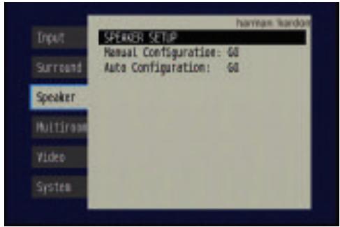
Figure 52 (repeated) - Speaker Setup Menu Screen
Select the Manual Configuration option, and the Manual Speaker Setup menu will appear. See Figure 89.
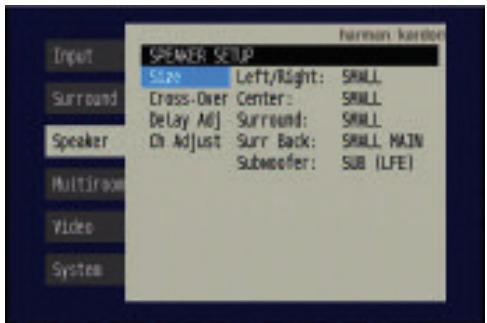
Figure 89 - Manual Speaker Setup Menu
There are four submenus in the Manual Speaker Setup Menu: Speaker Size, Speaker Crossover, Delay Adjust and Channel Adjust. As each submenu's name is highlighted, its settings will be displayed. To navigate the Manual Speaker Setup menus, press the Set Button when the desired submenu is highlighted, and the first line of the submenu will be highlighted. Press the Set Button to change a setting. Use the / Buttons to scroll through the options, pressing the Set Button again to select an option. Use the / Buttons to select another setting in the submenu. When you are finished making all of your adjustments in a particular submenu, press the Button to return to the list of submenus, and use the / Buttons to select another submenu.
If you have run EzSet/EQ, the values obtained during that process will appear in these menus. You may use them as a starting point for your adjustments, which is recommended, or you may reset the values in the Delay Adjust and Channel Adjust submenus.
Each submenu's settings are dependent upon the previous submenu, and therefore we recommend you visit the menus in the order shown.
Speaker Size Menu
Move the cursor to the Size line and press the Set Button to display the Speaker Size submenu. See Figure 89.
The Speaker Size menu lists each of the speaker groups. You will be programming the correct setting for each group, indicating how many speakers are in your system and what their capabilities are, based on the information you obtained in Step One - Determine Speaker Size. Each of the main speaker groups can be set to one of three settings: LARGE, SMALL or NONE. These settings don't refer to the physical size of the speaker, but rather to its frequency range. These may or may not turn out to be the same.
If the lower number of the frequency response for your speakers is less than 100Hz , choose the LARGE setting. If this number is 100Hz or greater, choose the SMALL setting. If you don't have a speaker installed in that position, choose NONE. You may record the speaker size setting in Table A5 in the appendix.
As you can see, the system requires you to use both speakers in a pair. For example, you can't connect just a front left speaker without a right speaker, or just a right surround (rear) speaker without a left one. However, you can connect only the front speakers, or both front and surround speakers without a center, or the front left/right and center speakers without any surrounds.
Usually you would not connect the surround back speakers without also connecting the front and side surround speakers. However, the AVR 347 has the capability to reassign the surround back amplifier channels to the multiroom system, enabling you to use these channels to power a pair of speakers in another room independently of the speakers you use in your main listening area. In that case you might connect speakers to the surround back/multiroom terminals without using the side surround speaker terminals at all.
LEFT/RIGHT: This line tells the AVR 347 the capabilities of your front left and right speakers. Use the / Buttons to select either SMALL or LARGE for these speakers.
CENTER: Move the cursor to the line for the center speaker, and use the / Buttons to select a setting for this speaker.
NOTE: If the receiver is currently in one of the Logic 7 surround modes, which will be the case the first time you turn on the receiver, you won't be able to set the center speaker to LARGE, due to the requirements of the Logic 7 processor. You may use the SMALL setting instead. As you listen to the receiver, if you find the SMALL setting is not satisfactory, change the surround mode to one of the Dolby Pro Logic II modes (using the Surround Setup menu, and return to this menu to change the center speaker to the LARGE setting.
SURROUND: Move the cursor to the line for the side surround speakers, and use the / Buttons to select the SMALL, LARGE or NONE setting for these two speakers.
SURR BACK: Use the Buttons to select the SMALL, LARGE or NONE setting for the surround back speakers.
The AVR 347 is one of the few receivers in its class to include multiroom capability. With assignable surround back amplifier channels, setting up a multiroom system is more convenient than ever, no longer requiring an external amplifier to power the remote speakers. This line indicates whether the surround back channels are in use with the multiroom system by indicating MAIN when the multiroom system is not in use and MULTI when it is. It is not possible to change the status of the surround back channels from this menu; the MAIN/MULTI indication is for information only. The status may only be changed by activating or deactivating the multiroom system using the MULTI ROOM SETUP menu as described in the Multiroom Operation section on page 58.
SUBWOOFER: Move the cursor to the line for the subwoofer, which is programmed a little differently. The subwoofer's "size" setting depends upon how you programmed the front left and right speakers.
-
If you set the front speakers to SMALL, the subwoofer setting will be SUB (LFE), and you won't be able to change it. All low-frequency information will always be sent to the subwoofer. If you don't have a subwoofer, you may wish to set your front speakers to LARGE so as not to lose this information, but you may need to lower the volume to avoid adverse results. We recommend that you either upgrade to full-range speakers or add a subwoofer to your system at the earliest opportunity.
-
If you set the front speakers to LARGE, you may select from three possible settings for the subwoofer.
-
SUB L/R+LFE: This setting sends all low-frequency information to the subwoofer, including both information that would normally be played through the front left and right speakers and the special low-frequency effects (LFE) channel information.
- SUB (LFE): This setting plays low-frequency information contained in the left and right program channels to the front speakers, and directs only the LFE channel information to the subwoofer.
- NONE: This setting steers all low-frequency information to the front speakers, and no information to the subwoofer output. Use this setting if you have a passive subwoofer, or a powered subwoofer that you connected to the front speaker outputs.
NOTE: If you are using a Harman Kardon HKTS speaker system, select the SMALL setting for the LEFT/RIGHT, CENTER, SURROUND and SURR BACK lines, and the subwoofer will automatically be set to SUB (LFE).
Move the cursor to the left to select the next submenu.
The speaker sizes may also be configured without using the on-screen menu system. Press the Speaker Setup Button on the remote, and use the / Buttons to select the desired speaker group (Front Speakers, Center Speaker, Surround Speakers, Surround Back Speakers, Subwoofer). Press the Set Button to display the current setting for the speaker group, and use the / Buttons again to change the setting. Press the Set Button to return to the previous display, or wait a few seconds for the AVR to return to normal operation on its own.
NOTE: The Speaker/Channel Indicators on the front panel of the receiver (see Figure 82) will display the speaker size settings as follows. For each speaker configured as SMALL, a single box will appear in the position for that speaker. For each speaker configured as LARGE, a double box will appear in its position. If a speaker is configured as NONE, no box will appear. The subwoofer will be indicated by a single box, or no box if no subwoofer has been configured. The letters inside the boxes appear when a digital signal is being received that has that channel discretely encoded. The letters flash when the signal is not present, such as when a DVD is paused. A line will connect the SBL and SBR boxes when a 6.1-channel signal is detected, indicating that the same signal is playing through both speakers.
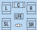
[SBL]

Figure 87 (repeated) - Speaker/Channel Input Indicators
Speaker Crossover Menu
On the Manual Speaker Setup menu, move the cursor to the Crossover X-OVER line and press the Set Button to display the Speaker Crossover menu. See Figure 90.
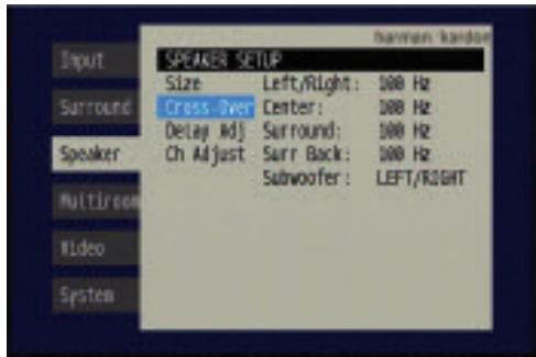
Figure 90 - Speaker Crossover Menu Screen
Setting the Speaker Crossover menu correctly ensures that your speakers are properly used so that they sound their best. Although you could skip this step the first time you use the receiver, we recommend that you take the few extra minutes to enter the correct crossover settings.
You may select from seven possible settings: 40Hz, 60Hz, 80Hz, 100Hz, 120Hz, 150Hz or 200Hz. Depending upon the frequency response of your speakers which you recorded in Step One - Determine Speaker Size, for each speaker group select the number that matches or is just above the low end of your speaker's frequency response. You may record the speaker crossover settings in Table A5 in the appendix.
The Subwoofer line sets the frequency for a low-pass filter that determines what information is sent to the subwoofer for playback. Since the subwoofer output combines low-frequency information for all channels, in order to make sure that no information is lost due to different speakers having different capabilities, the subwoofer filter should be matched to the highest crossover frequency used for any speaker group.
Examine each of your speaker-group settings in this menu, and determine which group is set to the highest frequency. Move the cursor to the Subwoofer line, press the Set Button and use the / Buttons to select that speaker group. If all speaker groups have the same setting, you may leave the Subwoofer filter at its factory default of the LEFT/RIGHT speaker group.
Move the cursor to the left to select the next sub menu.
It is not possible to adjust the speaker crossover settings without using the on-screen menu system.
Delay Adjust Menu
As explained above in Step Two – Measure Speaker Distances, sometimes the speakers are placed at different distances from the listening position, which can muddy the sound, as sounds are heard earlier or later than desired.
Even if all of your speakers are placed the same distance from the listening position, you should not skip this menu.
On the Manual Speaker Setup menu, move the cursor to the Delay Adjust line and press the Set Button to display the Delay Adjust menu. See Figure 91.
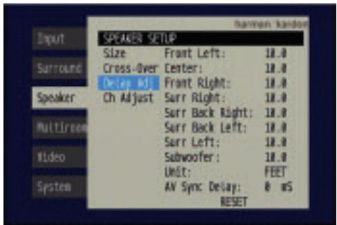
Figure 91 - Delay Adjust Menu Screen
This menu requires you to enter the distance from each speaker to the listening position, which you measured in Step Two – Measure Speaker Distances and noted in Table A3 in the appendix.
The default unit of measurement is in feet. If you wish to change the unit to meters, move the cursor down to the UNIT line, press the Set Button and use the / Buttons to change the unit to METER.
Use the / Buttons to move the cursor to the Front Left line; press the Set Button, then use the / Buttons to change the measurement as needed. Use the / Buttons to move to each speaker in turn - Center, Front Right, Surr Right, Surr Back Right, Surr Back Left, Surr Left and Subwoofer.
A/V SYNC DELAY: This line allows you to compensate for a situation in which one of your source devices, or your video display, introduces a significant amount of video processing that causes the audio and video parts of the signal to lose synchronization. This is known as a "lip sync" problem. You may delay the audio for all channels by up to 80 milliseconds to compensate.
NOTE: We recommend that you adjust the A/V Sync Delay using the Delay Button on the remote, rather than in this menu, so that you can view the picture while adjusting the audio delay. With the program playing, press the Delay Button, and the A/V SYNC DELAY message will appear on the front panel and in the semi-OSD display. Press the Set Button to display the current delay setting, and use the / Buttons to adjust the setting until the picture and sound are back in sync.
RESET: This line is used if you wish to reset all of the speaker delay settings to the factory default of 10 feet (3.0 meters) at once. Simply highlight it and press the Set Button. Move the cursor to the left to select the next submenu.
You may adjust the delay settings without using the on-screen menu system. Select a surround mode that uses all of the speakers in your system. Press the Delay Button on the remote to display the A/V SYNC DELAY message. If you wish to adjust A/V Sync Delay as described in the above note, press the Set Button to select it. Otherwise, use the
/ Buttons to scroll through the list of all loudspeakers in your system. Press the Set Button when the speaker you wish to adjust is displayed, and use the / Buttons again to change the setting. Press the Set Button to return to the previous display, or wait a few seconds for the AVR to return to normal operation on its own.
Step Four - Setting Channel Output Levels Manually
For a conventional 2-channel receiver, the balance control enables the user to control the stereo imaging by adjusting the relative loudness of the left and right channels, as heard at the listening position.
With up to seven main channels plus a subwoofer, imaging becomes both more critical and more complex. Unlike the rotary balance control, the goal of the AVR 347's channel output adjustment process is to examine the output level of each channel independently and ensure that each is heard at the listening position with equal loudness.
If you followed the instructions in the Initial Setup section, then you let EzSet/EQ handle this critical task for you, simply and automatically. However, if you prefer to make these adjustments manually, the AVR 347's Channel Adjust menu allows you to do so, either using the system's test tone or while playing source material. In addition, this is the only method for adjusting the level of the subwoofer.
You may use a handheld SPL meter (available at most electronics stores) set to the C-Weighting, Slow scale.
- Make sure all speakers have been connected correctly.
- Adjust the size, crossover and delay for each speaker in your system as described in Step Three.
- If you are using a handheld SPL meter with source material, such as a test disc or another audio selection, play it now and adjust the AVR's master volume control until the meter measures 75dB.
- There are several methods of adjusting the channel output levels, using either the test tone or source materials. In all cases, you may measure the channel levels in one of two ways:
a) By ear. Try to adjust the levels so that all channels sound equally loud.
b) Using a handheld SPL meter set to the C-Weighting, Slow scale. Try to adjust each channel so that the meter reads 75dB.
The best method of setting the output levels is by running EzSet/EQ, as described in the Initial Setup section. If any finer adjustments are desired, we recommend using the full-OSD system to make the adjustments while playing the AVR's built-in test tone and measuring the output using an SPL meter. Less effective would be to measure the output by ear. The adjustments may also be made using the remote's Test Tone command or Channel command. Although the Channel command is also accessible using the front-panel controls, we don't recommend doing so, as the measurements cannot be made from the listening position.
A. Using the Remote Control With the Test Tone
While sitting in the listening position, press the Test Button on the remote. The test tone will start playing at the front left channel. After a few seconds, it will move to the center channel, then the front right channel, surround right, surround back right, surround back left, surround left and finally the subwoofer, displaying the channel name on the front of the receiver and in the semi-OSD display, as well as the current level setting
(varies between -10dB and +10dB ). Press the / Buttons to adjust the level setting, and the tone will remain at that channel until several seconds after your last adjustment. When you have finished adjusting the levels, press the Test Button again to stop the tone. Measure the levels by ear, or using an SPL meter, as described above.
B. Using the Front-Panel or Remote-Control Channel Command
You may adjust the levels by pressing the Channel Button on the front panel, and the FRONT L LEVEL message will appear. Use the / Buttons on the front panel to select the desired speaker channel to adjust, and press the Set Button when the desired channel is displayed. The current level for that channel will appear, and you may adjust it using the / Buttons. Press the Set Button to return to the speaker channel choices. This method is not recommended, as you will not be able to measure the channel levels at the listening position. In addition, this method requires a source to be playing.
You may also access the Channel command by pressing the Channel Button on the remote. Use the / Buttons to select the desired speaker channel and press the Set Button, then use the / Buttons again to adjust the level. As with the front-panel controls, a source should be playing for best results. However, the source may be mixed to highlight certain channels at various times during the selection, which could skew the results when a different program is played.
C. Using the Full-OSD Menu
Next to EzSet/EQ, the full-OSD menu system offers the easiest and most flexible manner of setting output levels. Press the OSD Button to display the Menu System, and then navigate to the Speaker tab. Press the Set Button to display the Speaker Setup menu. Select Manual Configuration, press the Set Button and then navigate to the Channel Adjust line. Press the Set Button to display the Channel Adjust menu. See Figure 92.
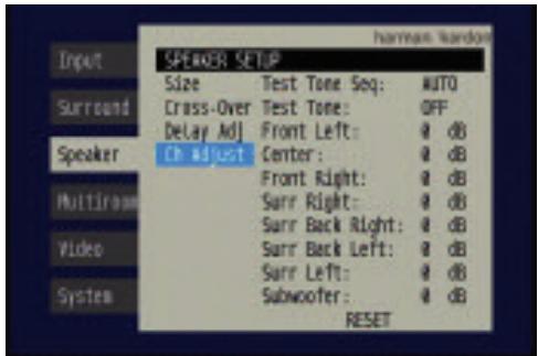
Figure 92 - Channel Adjust Menu Screen
All of the speaker channels will appear with their current level settings.
RESET: If you wish to start by resetting all of the levels to their factory defaults of OdB, navigate to this line and press the Set Button. The levels will be reset.
If you are using an external source to set your output levels, simply navigate to each channel, press the Set Button and use the / Buttons to adjust the level as desired.
If you would like to set your levels using the AVR 347's internal test tone, adjust the TEST TONE SEQ and TEST TONE lines as follows.
TEST TONE SEQ: When this setting reads AUTO, the test tone will automatically circulate to all channels, pausing for a few moments at each channel and then moving to the next channel several seconds later, as indicated by the highlight bar. You may adjust the level for any channel when the test tone is paused there by using the Buttons. You may also use the Buttons at any time to move the cursor to another line, and the test tone will follow the cursor.
When this setting reads MANUAL, the test tone will not move to the next channel until you use the / Buttons to move it.
TEST TONE: This line determines whether the test tone is active. To begin the process of setting the levels press the Set Button and use the / Buttons to change the setting to ON. Any time you manually move the cursor out of the channel listings area of the screen, this setting will automatically change to OFF, stopping the test tone.
NOTE: Setting the channel levels while one surround mode is active does not necessarily carry over to all other modes. We recommend that after you have set the levels satisfactorily in one mode, you note the results and change to other surround modes. For those modes that don't reflect your level settings, you may either copy the settings you obtained (as a short cut), or redo the procedure to determine the correct settings for those surround modes.
Video Adjustments
The AVR 347 includes sophisticated DCDi by Faroudja video processing that delivers enhanced video quality, even for older analog video source components, as well as upgraded on-screen displays. When upscaling video materials from a lower resolution to a higher one (the AVR 347 upscales to a maximum of 720p), the processor is adding pixels to the original image. Sometimes when converting interlaced video (displays all odd rows then all even rows of the frame) to progressive-scan video (displays all rows at once) and increasing the resolution, the interpolation of new pixels can cause jagginess, or a staircase effect, at edge transitions, such as the stripes in an American flag. Faroudja engineers developed the DCDi (Directional Correlational Deinterlacing) algorithm to ensure that the additional pixels follow the edge, virtually eliminating the jagginess and enhancing upscaled images.
The video processor is set at the factory to automatically provide the best picture as it detects the capabilities of your video display and the incoming source video signals. However, you may experiment with the Video Setup menu adjustments to try to improve the picture further. The Video Setup menu includes a reset feature in the event you wish to return to the factory defaults and try again.
To access the Video Setup menu, press the OSD Button to display the menu system, and navigate to the Video tab. Press the Set Button to access the Video Setup menu, shown in Figure 93.
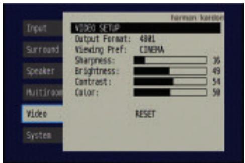
Figure 93 - Video Setup Menu Screen
OUTPUT FORMAT: This setting is used to specify the resolution of the AVR's video output as 480i, 480p or 720p.
When the HDMI Output is active, 480i output is not available. If you select the 480i setting and the video display is capable of 720p resolution, the AVR will automatically select the higher resolution. If the display is not capable of 720p resolution, the AVR will select the 480p setting.
If your source signal is 1080i or 1080p, it will be passed through to the HDMI Output as is (unless the source is analog component video), but you may not select that output format on this line, as upscaling to these resolutions is not supported. If you are using the Component Video Monitor Outputs, you will not be able to view 1080p materials, but 1080i sources will be passed through. In any event, when the source signal is 1080i or 1080p, the semi-OSD messages will not appear, including the volume bar. Full-OSD displays will appear, but at a lower resolution.
VIEWING PREFERENCE: This setting allows you to select factory-predetermined picture setting that is optimized for various types of program materials. The available options are CINEMA, SPORT, NATURE and VIVID.
SHARPNESS: You may adjust the Sharpness setting from 0 to 100 in increments of 4 units. We recommend leaving this setting as low as possible because, contrary to what you might expect, a less sharp image can appear clearer on screen. In addition, increasing the Sharpness requires additional video processing, which may lead to loss of sync with the audio or visual artifacts. However, there is no harm in experimenting with this setting.
BRIGHTNESS: This control adjusts the level at which black is delivered. We recommend leaving it at its factory setting, although there is no harm in experimenting if you are using a test signal.
CONTRAST: This control adjusts the difference between black and white in the picture. We recommend leaving it at its factory setting, although there is no harm in experimenting if you are using a test signal.
COLOR: This control adjusts the hue of the colors in the picture, and may be set between 0 and 99. Select a setting in which people and objects on screen look natural. There is no "recommended" setting, and no harm in experimenting.
RESET: If you wish to return the video settings to their factory defaults, select this line and press the Set Button.
Multiroom Operation
The AVR 347 offers the benefits of multiroom operation, a rarity in a receiver this affordable. With the multiroom system in use, you may enjoy an exciting 5.1-channel home theater presentation in the main listening area, while others listen to the same materials or an entirely different presentation in another room.
Although installation of a multiroom system is not complicated, it is often accomplished by running wires inside walls. We urge you to check your local building codes and comply with the requirements for in-wall wiring systems to prevent the possibility of a dangerous situation. If you have any questions about installing a multiroom system, we strongly recommend that you contact a professional custom installer in your area.
Installing a Multiroom System
A typical multiroom system consists of only one remote room in the remote zone. That is, you connect only one pair of loudspeakers to the AVR 347, placing those speakers in the remote room the same way you would place the front left and right speakers in the main listening room. It is not recommended that you separate the left and right multiroom speakers, unless you will only use the system with the tuner as the source, and you have pressed the Tuning Mode Button to select monaural operation for FM radio stations.
If you wish to use the AVR 347 with more than one remote room, you will need to purchase a multichannel external amplifier that enables you to connect several pairs of loudspeakers, or use an A-BUS hub. However, the AVR 347 only outputs one remote zone, meaning that only one signal is sent through the multiroom system. All remote rooms will hear the same source, even when a multichannel amplifier or A-BUS hub is used.
There are three ways of connecting the remote speakers to the AVR 347:
a) Connect the speakers to the left and right Surround Back/Multiroom Speaker Outputs on the rear panel of the AVR 347. This is the simplest type of multiroom system. However, it is not recommended for long speaker-wire runs (e.g., more than 25 feet), as the audio signal tends to degrade over long distances. If your application would require a long speaker-wire run, consider option b) below.
b) Purchase an external amplifier. Connect the Surround Back/Multiroom Preamp Outputs or the Multiroom Audio Outputs to the amplifier's inputs. You may place the amplifier either in the main listening room or the remote room. Placing the amplifier in the main listening room would require the use of long speaker wires to reach the remote room, while placing the amplifier in the remote room calls for the opposite - long interconnect cables and short speaker wires.
c) Buy an A-BUS in-wall amplified module, such as the Harman Kardon AB 1 or AB 2, and connect it to the A-BUS port for use with a single pair of remote speakers. If you purchase an A-BUS hub, such as the Harman Kardon ABH 4 or ABH 4000, you may connect up to four in-wall modules to each hub, or you may cascade hubs to create a whole-house audio distribution system that delivers audio to almost every room in your home. A-BUS offers the benefits of simplicity,
expandability and the inclusion of IR support, all communicated via single-cable connections and requiring no external power amplifiers.
When you use either the Surround Back/Multiroom Speaker Outputs or the Surround Back/Multiroom Preamp Outputs for a multiroom system, you will not be able to use the surround back speakers with your main system, which will be limited to 5.1 channels. However, when the multiroom system is turned off, you may relocate your remote speakers (if that's practical) to the main listening room for 7.1-channel operation.
If you are not using A-BUS components, you may install an optional remote infrared (IR) receiver in the remote room and connect it to the Multiroom IR Input on the back of the receiver. This lets you use the included Zone II remote, a keypad or another control device to turn the multiroom system on or off, select a source input, and operate any source devices that are connected in daisychain fashion to the AVR 347's Remote IR Output.
You may use the above connection methods simultaneously to increase the total number of remote rooms in your system. Remember that sending control commands from one room in the system will affect the entire remote zone of the multiroom system.
Operating the Multiroom System
The AVR 347's multiroom system is accessed using the on-screen Multi Room Setup menu. Press the OSD Button to display the Menu System, and use the / Buttons to navigate to the Multi Room tab. See Figure 48. Press the Set Button to display the Multi Room Setup menu. See Figure 94.
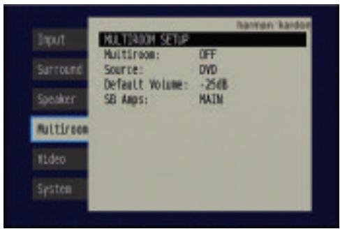
Figure 94 - Multiroom Setup Menu Screen
Multi Room: This line is used to turn the multiroom system on or off. When no one is listening in the remote room, leave this setting at the default of OFF.
Source: This line indicates the source input selected for the remote zone. You may select any source input for which a device has been connected to the AVR 347, even when a different source is being enjoyed in the main listening area. However, if the tuner has been selected for simultaneous operation in both the main listening area and the remote zone, listeners in both areas will hear the same radio station.
Default Volume: The volume is controlled separately for the remote zone.
SB Amps: This line is used to reassign the surround back channels to the multiroom system, enabling you to connect speakers for a remote room without using an external amplifier (unless you are connecting the
Surround Back Preamp Outputs to an external amplifier to power the speakers). When this line is set to MULTI, you may only configure the main listening room for up to 5.1 channels. EzSet/EQ will only configure the main 5.1-channel system, and you will need to use the Manual Configuration section of the Speaker Setup menu to configure the remote speakers.
The three multiroom settings may also be accessed by pressing the Multiroom Button on the remote (see Figure 95). The first press displays the MULTI ON/OFF setting, which functions the same as the first line of the Multiroom Setup menu. You may use the / Buttons to scroll to the MULTI INPUT and MULTI LEVEL settings, which perform the same functions as the Source and Default Volume lines of the Multiroom Setup menu. For each of the three settings, press the Set Button to adjust the setting, using the / Buttons to select the desired option.
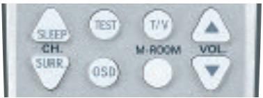
Figure 95 - Multiroom Button
System Settings
The AVR 347 offers several system settings that allow you to make the receiver easier to use rather than directly affecting performance. Most of these settings may be accessed from the System Setup menu, which is selected by pressing the OSD Button and navigating to the System tab. Press the Set Button to display the System Setup Menu. See Figure 96.
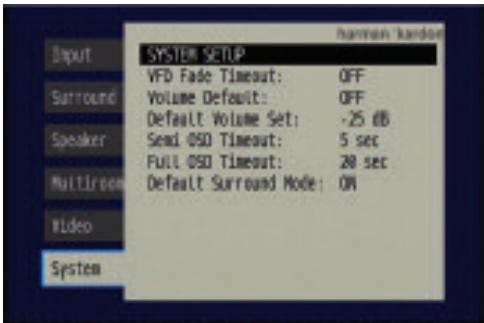
Figure 96 - System Setup Menu Screen
VFD Fade Timeout: Some people find the brightness of the AVR's front-panel display distracting during movies or listening sessions. It's possible to dim the front-panel display completely using the Dim function (see below). This sets the display to remain dark most of the time, lighting up only when a button is pressed or a remote command is received, and going dark again five seconds after the last command. The VFD Fade Timeout feature also causes the display to light up only when a button is pressed or a change in the incoming signal is detected, but the display immediately begins to fade to dark.
Select a time-out period of between 3 and 10 seconds, or select OFF if you prefer to leave the displays on at all times or to use the Dim function.
Volume Default and Default Volume Set: These two settings are used together to program a volume level the AVR will always switch to when turned on. This feature avoids discomfort for listeners in case the last user turned the volume very high.
Press the OSD Button to remove the display from the screen so that you may adjust the volume to a desired level while a source is playing. Make a note of the number that appears in the display, and return to the System Setup menu. At the Default Volume Set line, select the desired volume setting, and activate the feature by setting Volume Default to ON.
NOTE: Although volume is normally displayed in 0.5dB increments, the default volume setting only allows whole numbers.
Semi OSD Timeout: At this line, you may program the amount of time (2 to 5 seconds) the two-line semi-OSD on-screen messages remain visible, or you may deactivate the semi-OSD display altogether if you find it distracting. These messages will continue to appear on the front panel of the receiver.
NOTE: The semi-OSD displays are not available when a 1080i or 1080p high-definition video source is in use.
Full OSD Timeout: At this line, you may program the amount of time (20, 30, 40 or 50 seconds) the full-OSD menus remain visible on screen. The full-OSD system may not be deactivated.
Default Surround Mode: This setting determines how the AVR 347 will handle Dolby Digital and DTS sources. For the purposes of this setting, the "default surround mode" means the mode encoded in the program, such as Dolby Digital 5.1. With this setting ON, the receiver will always use the default surround mode encoded in the program. When this setting is changed to OFF, the receiver will use the surround mode you selected the last time this type of audio stream was detected.
Dolby Digital 2.0 signals default to the Dolby Pro Logic II Movie mode, but you may select another Dolby surround mode manually. For PCM and analog sources, the factory default surround mode is Logic 7 Music. In general, the receiver will use the surround mode selected the last time that type of signal was received.
Dim Function
Some people find the front-panel messages distracting and would prefer to dim them or turn them off altogether. When the display is dimmed or darkened, it will return to full brightness for five seconds any time a command is received before dimming or darkening again.
To dim the display:
- Press the Dim Button on the remote. Each button press will cycle through the three settings of:
VFD FULL: Normal brightness
VFD HALF: Display is dimmed but still visible; the light inside the volume knob goes dark
VFD OFF: Display goes completely dark except for the Power Indicator to remind you that the receiver is turned on
- Press the Set Button on the front panel and hold it for about five seconds. A message indicating the current brightness setting (see above) will appear in the display. Use the front-panel Buttons to change the setting, and press the Set Button to select it.
Advanced Remote Control Functions
The AVR 347 remote control not only operates the AVR 347, but it also serves as a universal remote that may be programmed to operate many other home theater components, as described in the Installation section. Each time you select one of your other components, the AVR remote switches to the control functions for that component. Since many buttons have unique functions for each component, refer to the Function List in the Appendix for assistance in operating your other components. The function of each button will not necessarily correspond to the label printed on the button.
Punch-Through Programming
The AVR 347 remote's punch-through feature allows you to select one component for the remote to operate, while simultaneously setting certain groups of controls to operate another component. For example, while using the AVR to control surround modes and other audio functions, you may operate the transport controls of your DVD player. Or while using the remote to control video functions on your TV, you may use your cable box to change channels and the AVR to control the volume.
NOTE: It is not necessary to program the remote to control your DVD player's transport controls while the AVR, VID2 or VID3 devices are in use, as the remote is preprogrammed at the factory with this function.
To program punch-through control while operating any device:
- Press and hold the Input Selector (or AVR selector) for the main device the remote will be operating until the Program LED flashes and the remote enters Program mode.
- Select the type of punch-through programming.
a) To program volume control punch-through, press the Volume Up Button.
b) To program channel control punch-through, press the Volume Down Button.
c) To program transport control punch-through, press the Play Button.
- Press the Input Selector (or AVR selector) for the device whose volume, channel or transport controls you would like to be active while operating the device you selected in the first step. The LED will flash green to confirm the programming.
For example, if you wish to watch your TV (programmed into the Video 3 Button) while changing channels using your cable box (Video 2), first press the Video 3 Button until the Program LED flashes. Then press the Volume Down Button, followed by the Video 2 Button.
To undo punch-through programming, follow the same steps as above, but press the same Input (or AVR) Selector in Steps 1 and 3.
You may reassign the transport control punch-through programming for the AVR, VID2 and VID3 devices to other devices, such as CD. If you wish to remove transport control punch-through altogether for the AVR, VID2 or VID3 device, follow the same procedure as for programming punch-through, but in Step 3 press either of the other two of these three special selector buttons. For example, to remove punch-through transport control from the VID3 device so that pressing any of the transport controls will have no effect in that device mode, press and hold VID3 until the Program Indicator LED flashes in amber, then press the Play button, followed by either the AVR or VID2 Button.
Macros
Macros are used to program sequences of up to 19 commands that are executed with a single button press. Macros are well suited for power on and off commands, or to send out a favorite multidigit channel number with one button press, or to have the ability to send out a code sequence to control another device while the remote is operating one device, but with more flexibility than the built-in punch-through controls.
Some commands may not be programmed into macros: Mute, Dim, Channel Up/Down, or any of the surround mode commands.
NOTE: Use caution when programming complicated macros. It isn't possible to program a pause or delay before sending commands after Power On, and the component may not be ready to respond to commands instantaneously after powering on.
To program, or "record" a macro, follow these steps:
- Simultaneously press and hold one of the four Macro Buttons (or the Power On Button) and the Mute Button to enter Program mode.
- Press the Input (or AVR) Selector for each device before you enter commands to be transmitted to that device. This step counts as one of the 19 commands allowed for each macro.
NOTE: Even if you previously switched one of the dual-source Input Selectors (DVD/CD, TAPE/THE BRIDGE, HDMI 1/HDMI 2) to the primary or secondary source prior to programming the macro, the remote always requires you to press any of these selectors once to program the macro to select the primary source and twice for the secondary source.
- For the Power On command, DO NOT press the Power On Button. Press the Mute Button instead.
- Press the Power Off Button to program the Power Off command.
- Press the Sleep Button to end the programming process.
It isn't possible to "edit" a command within a macro. However, you may erase the macro as follows:
- Simultaneously press and hold the Mute Button and the Macro Button containing the macro until the Program LED flashes.
- Press the Surround Button to erase the macro.
Resetting the Remote
To reset the remote to its factory defaults, simultaneously press and hold any Input Selector and the "0" Numeric key. When the Program LED flashes in amber, enter the code "333". When the green LED goes out, the remote will have been fully reset.
Processor Reset
There may be instances when you wish to fully reset the AVR 347 to its factory defaults, or the unit may behave erratically after a power surge.
To correct erratic behavior, first try turning the Master Power Switch off and unplugging the AC power cord for at least three minutes. Plug the cord back in and turn the receiver back on. If this doesn't help, try a system reset.
NOTES:
- A system reset erases all user configurations, including speaker and level settings and tuner presets. After a reset, you will need to reenter all of these settings.
- The RS-232 Reset Button on the rear panel of the AVR 347 does not perform a system reset. DO NOT press the RS-232 Reset Button.
To reset the AVR 347, place the receiver in Standby mode (press the front-panel Standby/On Switch so that the Power Indicator turns amber). Then press and hold the front-panel Tone Mode Button for at least five seconds until the RESET message appears in the display.
If the receiver still does not function correctly after a processor reset, contact an authorized Harman Kardon service center for assistance. Authorized service centers may be located by visiting our Web site at www.harmankardon.com.
Memory
If the AVR 347 is unplugged or experiences a power outage, it will retain user settings for up to four weeks.
TROUBLESHOOTING GUIDE
| SYMPTOM | CAUSE | SOLUTION |
| Unit does not function when Main Power Switch is pushed | • No AC Power | • Make certain AC power cord is plugged into a live outlet • Check to see whether outlet is switch-controlled |
| Display lights, but no sound or picture | • Intermittent input connections • Mute is on • Volume control is down | • Make certain that all input and speaker connections are secure • Press Mute Button • Turn up volume control |
| No sound from any speaker; light around power switch is red | • Amplifier is in protection mode due to possible short • Amplifier is in protection mode due to internal problems | • Check speaker wire connections for shorts at receiver and speaker ends • Contact your local Harman Kardon service center |
| No sound from surround or center speakers | • Incorrect surround mode • Input is monaural • Incorrect configuration • Stereo or Mono program material | • Select a mode other than Stereo • There is no surround information from mono sources • Check speaker mode configuration • The surround decoder may not create center- or rear-channel information from nonencoded programs |
| Unit does not respond to remote commands | • Weak batteries in remote • Wrong device selected • Remote sensor is obscured | • Change remote batteries • Press the AVR selector • Make certain front panel sensor is visible to remote or connect an optional remote sensor |
| Intermittent buzzing in tuner | • Local interference | • Move unit or antenna away from computers, fluorescent lights, motors or other electrical appliances |
| Letters flash in the channel indicator display and digital audio stops | • Digital audio feed paused | • Resume play for DVD • Check that correct digital input is selected |
| Surround Back Speaker settings cannot be accessed, and test tone does not play through Surround Back Speakers | • Multiroom system has been turned on, and the surround back channels were reassigned to multiroom operation | • Use the OSD menu system to access the MULTI ROOM SETUP menu and change the SB Amps setting to MAIN. |
| The XM Preview Channel (001) is silent | • XM antenna is not plugged in • XM antenna is not located in such a way as to enable reception | • Make sure you are using a home audio XM antenna module designed for use with XM Ready home audio equipment, and that the module is plugged into the XM Radio Jack on the rear panel of the receiver. • The XM Antenna module needs to be placed with an unobstructed view of the southern sky, or within range of an XM terrestrial repeater. If necessary, purchase an extension cable from your XM Radio dealer. |
| Unable to activate Program mode on remote | • Input Selector not held for at least 3 seconds. | • The selector will light as you initially press it, and go dark as you hold it down. Wait at least 3 seconds for the selector to light up again, and the Program LED will flash. |
| Unable to assign a device to HDMI 1 or 2 selectors | • Invalid device assignment attempted. | • Only the DVD, VCR (includes DVR), cable or satellite (CBL/SAT selector) devices may be assigned to the HDMI 1 or 2 selectors. |
| Remote behaves erratically | • Buttons are pressed too hard. | • Always press remote control buttons as gently as possible. |
| Additional information on troubleshooting possible problems with your AVR 347, or installation-related issues, may be found in the list of "Frequently Asked Questions", which is located in the Product Support section of our Web site at www.harmarkardon.com. | ||
Audio Section
Stereo Mode
Continuous Average Power (FTC)
70 Watts per channel, 20Hz-20kHz
@ < 0.07% THD, both channels driven into 8 ohms
Seven-Channel Surround Modes
Power per Individual Channel
Front L&R channels:
55 Watts per channel
@ <0.07% THD, 20Hz-20kHz into 8 ohms
Center channel:
55 Watts @ <0.07% THD, 20Hz-20kHz into 8 ohms
Surround (L & R Side, L & R Back) channels:
55 Watts per channel
@ <0.07% THD, 20Hz-20kHz into 8 ohms
Input Sensitivity/Impedance
Linear (High-Level) 200mV/47k ohms
Signal-to-Noise Ratio (IHF-A)
200mV/47k ohms
Surround System Adjacent Channel Separation
Pro Logic I/II 40dB
Dolby Digital (AC-3) 55dB
DTS 55dB
Frequency Response
@ 1W (+0dB, -3dB) 10Hz -130kHz
High Instantaneous
Current Capability (HCC) ±35 Amps
Transient Intermodulation
Distortion (TIM) Unmeasurable
Slew Rate 40V/μsec
FM Tuner Section
Frequency Range 87.5-108.0MHz
Useable Sensitivity IHF 1.3 V / 13.2dBf
Signal-to-Noise Ratio Mono/Stereo 70/68dB
Distortion Mono/Stereo 0.2/0.3%
Stereo Separation 40dB @ 1kHz
Selectivity ±400kHz, 70dB
Image Rejection 80dB
IF Rejection 90dB
The AVR 347 is Simplay HD™-verified for compatibility via the HDMI connection with other Simplay HD-verified products.
Please register your AVR 347 on our Web site at
www.harmankardon.com.
NOTE: You'll need the product's serial number.
At the same time, you can choose to be notified about our new products and/or special promotions.
AM Tuner Section
Frequency Range 520-1720kHz
Signal-to-Noise Ratio 45dB
Useable Sensitivity Loop 500 V
Distortion 1kHz, 50% Mod 0.8%
Selectivity ±10kHz, 30dB
Video Section
Television Format NTSC
Input Level/Impedance 1Vp-p/75 ohms
Output Level/Impedance 1Vp-p/75 ohms
Video Frequency Response
(Composite and S-Video) 10Hz-8MHz (-3dB)
Video Frequency Response
(Component Video)
HDMI™
General
Power Requirement AC 120V/60Hz
Power Consumption 65W idle, 540W maximum
(7 channels driven)
Dimensions (Product)
Width
Height
Depth
(Shipping)
22 inches (559mm)
10-1/2 inches (267mm)
18-1/4 inches (464mm)
(Product)
Weight 30.6 lb (13.9kg)
(Shipping)
35.6 lb (16.2kg)
Depth measurement includes knobs, buttons and terminal connections.
Height measurement includes feet and chassis.
All features and specifications are subject to change without notice.
Harman Kardon and Logic 7 are trademarks of Harman International Industries, Incorporated, registered
in the United States and/or other countries. EzSet/EQ, ^TM Bridge ^a and Designed to Entertain are trademarks
of Harman International Industries, Incorporated
A-BUS is a registered trademark of LeisureTech Electronics Pty Ltd.
Apple, iTunes and iPod are trademarks of Apple Inc., registered in the U.S. and other countries.
Shuffle is a trademark of Apple Inc.
Audiovox is a registered trademark of Audiovox Corporation.
Blu-ray Disc is a trademark of the Blu-ray Disc Association.
CEA is a registered trademark of the Consumer Electronics Association.
Cirrus Logic is a registered trademark of Cirrus Logic, Inc.
Dolby, Pro Logic and the double-D symbol are trademarks of Dolby Laboratories.
Manufactured under license from Dolby Laboratories.
"DTS" and "DTS ES|Neo:6" are registered trademarks of DTS, Inc. "96/24" is a trademark of DTS, Inc.
Faroudja and DCDi by Faroudja are registered trademarks of Genesis Microchip Inc.
HD-DVD is a trademark of the DVD Format/Logo Licensing Corporation (DVD FLLC).
HDMI is a trademark of HDMI Licensing LLC.
Microsoft and Xbox are registered trademarks of Microsoft Corporation in the United States and other countries.
SACD is a trademark of Sony Corporation.
The Simplay HD logo and the Simplay, Simplay HD and Simplay Labs trademarks are owned by Silicon Image, Inc. and are used under license from Silicon Image, Inc. and/or Simplay Labs, LLC
TIVo is a registered trademark of TIVo Inc.
XM and XM Ready are registered trademarks of XM Satellite Radio.
Appendix - Default settings, worksheets, remote product codes
Table A1 - Source Input Setting Defaults
| Source | DVD | HDMI 1 | HDMI 2 | Video 1 | Video 2 | Video 3 | Video 4 | The Bridge/DMP | CD | Tape | Tuner | 6-/8-Channel | XM |
| Title | TUNER | XM | |||||||||||
| Video Input | Comp V 1 | HDMI 1 | HDMI 2 | Comp V 2 | Comp V 3 | Composite | Composite | The Bridge/DMP | Comp V1 | Comp V1 | Comp V1 | Comp V1 | Comp V1 |
| Audio Input | Coax 1 | HDMI 1 | HDMI 2 | Analog | Optical 1 | Analog | Analog | Analog (The Bridge/DMP) | Analog | Analog | Analog (Tuner) | Analog (6-/8-Channel) | Analog (Tuner) |
| Auto Poll | On | Off | Off | On | On | On | On | Off | On | On | Off | Off | Off |
| Surround Mode† | Logic 7 7CH Music | Logic 7 7CH Music | Logic 7 7CH Music | Logic 7 7CH Music | Logic 7 7CH Music | Logic 7 7CH Music | Logic 7 7CH Music | Logic 7 7CH Music | Logic 7 7CH Music | Logic 7 7CH Music | Logic 7 7CH Music | Logic 7 7CH Music | Logic 7 7CH Music |
- The default shown is the preferred surround mode for PCM and Analog audio sources.
Table A2 - Speaker/Channel Setting Defaults
| Source | DVD | HDMI 1 | HDMI 2 | Video 1 | Video 2 | Video 3 | Video 4 | The Bridge/DMP | CD | Tape | Tuner | 6-/8-Channel | XM |
| Left/Right Speaker Size | Small | Small | Small | Small | Small | Small | Small | Small | Small | Small | Small | Large | Small |
| Center Speaker Size | Small | Small | Small | Small | Small | Small | Small | Small | Small | Small | Small | Large | Small |
| Surround Speaker Size | Small | Small | Small | Small | Small | Small | Small | Small | Small | Small | Small | Large | Small |
| Surround Back Speaker Size | Small | Small | Small | Small | Small | Small | Small | Small | Small | Small | Small | Large | Small |
| Subwoofer | Sub | Sub | Sub | Sub | Sub | Sub | Sub | Sub | Sub | Sub | Sub | Sub | Sub |
| Left/Right Speaker Crossover | 100Hz | 100Hz | 100Hz | 100Hz | 100Hz | 100Hz | 100Hz | 100Hz | 100Hz | 100Hz | 100Hz | N/A | 100Hz |
| Center Speaker Crossover | 100Hz | 100Hz | 100Hz | 100Hz | 100Hz | 100Hz | 100Hz | 100Hz | 100Hz | 100Hz | 100Hz | N/A | 100Hz |
| Surround Speaker Crossover | 100Hz | 100Hz | 100Hz | 100Hz | 100Hz | 100Hz | 100Hz | 100Hz | 100Hz | 100Hz | 100Hz | N/A | 100Hz |
| Subwoofer Crossover | Left/Right | Left/Right | Left/Right | Left/Right | Left/Right | Left/Right | Left/Right | Left/Right | Left/Right | Left/Right | Left/Right | N/A | Left/Right |
Table A3 - Delay Setting Defaults
| Speaker Position | Distance From Speaker to Listening Position | Your Delay Settings |
| Front Left | 10 feet | |
| Center | 10 feet | |
| Front Right | 10 feet | |
| Surround Right | 10 feet | |
| Surround Left | 10 feet | |
| Subwoofer | 10 feet | |
| AV Sync Delay | 0mS |
Table A4 - Source Input Settings
| Source | DVD | HDMI 1 | HDMI 2 | Video 1 | Video 2 | Video 3 | Video 4 | The Bridge/DMP | CD | Tape | Tuner | 6-/8-Channel | XM |
| Title | |||||||||||||
| Video Input | |||||||||||||
| Audio Input | The Bridge/DMP | Tuner | 6-/8-Channel | Tuner | |||||||||
| Auto Poll | --- | --- | --- | ||||||||||
| Surround Mode | |||||||||||||
| Tone Mode | |||||||||||||
| Bass | |||||||||||||
| Treble | |||||||||||||
| Video Mode |
Table A5 - Speaker/Channel Settings
| Source | DVD | HDMI 1 | HDMI 2 | Video 1 | Video 2 | Video 3 | Video 4 | The Bridge/DMP | CD | Tape | Tuner | 6-/8-Channel++ | XM |
| Left/Right Speaker Size | N/A | ||||||||||||
| Center Speaker Size | N/A | ||||||||||||
| Surround Speaker Size | N/A | ||||||||||||
| Subwoofer | N/A | ||||||||||||
| Left/Right Speaker Crossover | N/A | ||||||||||||
| Center Speaker Crossover | N/A | ||||||||||||
| Surround Speaker Crossover | N/A | ||||||||||||
| Subwoofer Crossover | N/A | ||||||||||||
| Left Channel Level++ | |||||||||||||
| Right Channel Level++ | |||||||||||||
| Center Channel Level++ | |||||||||||||
| Surround Left Channel Level++ | |||||||||||||
| Surround Right Channel Level++ | |||||||||||||
| Surround Back Left Channel Level++ | |||||||||||||
| Surround Back Right Channel Level++ | |||||||||||||
| Subwoofer Channel Level++ |
The 6-8 Channel Inputs are "direct" inputs, meaning their signals are passed directly to the volume control without any bass management processing. Thus, the speaker sizes are always full range, and it isn't possible to adjust speaker size or crossover.
+†† Channel levels vary by surround mode rather than source input.
Table A6 - Remote Control Codes
| Source Input | Product Type (circle one) | Remote Control Code |
| Video 1 | VCR, PVR | |
| Video 2 | Cable, Satellite | |
| Video 3 | TV | |
| Video 4 | TV | |
| DVD | DVD | |
| CD | CD, CDR | |
| Tape | Cassette | |
| HDMI 1 | DVD, VCR, PVR, Cable Satellite | |
| HDMI 2 | DVD, VCR, PVR, Cable Satellite |
Table A7 - System Settings
| Feature | Default Setting | Your Setting |
| VFD Fade Timeout | Off | |
| Volume Default | Off | |
| Default Volume Set | -25dB | |
| Semi-OSD Timeout | 5 seconds | |
| Full-OSD Timeout | 20 seconds | |
| Default Surround Mode | On |
Copyright (c) 2003 by Bitstream, Inc. All Rights Reserved. Bitstream Vera is a trademark of Bitstream, Inc.
Permission is hereby granted, free of charge, to any person obtaining a copy of the fonts accompanying this license ("Fonts") and associated documentation files (the "Font Software"), to reproduce and distribute the Font Software, including without limitation the rights to use, copy, merge, publish, distribute, and/or sell copies of the Font Software, and to permit persons to whom the Font Software is furnished to do so, subject to the following conditions:
The above copyright and trademark notices and this permission notice shall be included in all copies of one or more of the Font Software typefaces.
The Font Software may be modified, altered, or added to, and in particular the designs of glyphs or characters in the Fonts may be modified and additional glyphs or characters may be added to the Fonts, only if the fonts are renamed to names not containing either the words "Bitstream" or the word "Vera".
This License becomes null and void to the extent applicable to Fonts or Font Software that has been modified and is distributed under the "Bitstream Vera" names.
The Font Software may be sold as part of a larger software package but no copy of one or more of the Font Software typefaces may be sold by itself.
THE FONT SOFTWARE IS PROVIDED "AS IS", WITHOUT WARRANTY OF ANY KIND, EXPRESS OR IMPLIED, INCLUDING BUT NOT LIMITED TO ANY WARRANTY OF MERCHANTABILITY, FITNESS FOR A PARTICULAR PURPOSE AND NONINFRINGEMENT OF COPYRIGHT, PATENT, TRADEMARK, OR OTHER RIGHT. IN NO EVENT SHALL BITSTREAM OR THE GNOME FOUNDATION BE LIABLE FOR ANY CLAIM, DAMAGES OR OTHER LIABILITY, INCLUDING ANY GENERAL, SPECIAL, INDIRECT, INCIDENTAL, OR CONSEQUENTIAL DAMAGES, WHETHER IN AN ACTION OF CONTRACT, TORT OR OTHERWISE, ARISING FROM, OUT OF THE USE OR INABILITY TO USE THE FONT SOFTWARE OR FROM OTHER DEALINGS IN THE FONT SOFTWARE.
Except as contained in this notice, the names of Gnome, the Gnome Foundation, and Bitstream Inc., shall not be used in advertising or otherwise to promote the sale, use or other dealings in this Font Software without prior written authorization from the Gnome Foundation or Bitstream Inc., respectively. For further information, contact: fonts at gnome dot org.
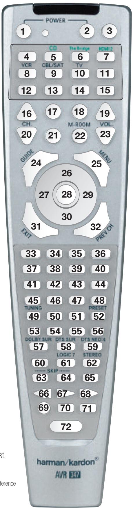
Figure 97 - Remote Control Function List Reference
Refer to the numbered buttons in Figure 97 when using the Function List.
Table A8 - Remote Control Function List
| No. | Button Name | AVR Function | DVD | CD/CD-R | Tape | VCR (VID1) | TIVo (VID1) | CBL (VID2) | SAT (VID2) | TV (VID3/VID4) | Bridge (DMP) | XM | HDMI 1/2 |
| 1 | Power On | Power On | Power On | Power On | Power On | Power On/Off | Power On | Power On | Power On | Power On | Power On | ||
| 2 | Power Off | Power Off | Power Off | Power Off | Power Off | TV Power | Power Off | Power Off | Power Off | Power Off | Power Off | ||
| 3 | Mute | Mute | Mute | Mute | Mute | Mute | Mute | Mute | Mute | Mute | Mute | Mute | |
| 4 | AVR | AVR Select | AVR Select | AVR Select | AVR Select | AVR Select | AVR Select | AVR Select | AVR Select | AVR Select | AVR Select | AVR Select | AVR Select |
| 5 | DVD/CD | DVD Input Select | DVD Select | DVD Select | DVD Select | DVD Select | DVD Select | DVD Select | DVD Select | DVD Select | DVD Select | DVD Select | DVD Select |
| CD Input Select | CD Select | CD Select | CD Select | CD Select | CD Select | CD Select | CD Select | CD Select | CD Select | CD Select | CD Select | ||
| 6 | Tape/ Bridge | Tape Select | Tape Select | Tape Select | Tape Select | Tape Select | Tape Select | Tape Select | Tape Select | Tape Select | Tape Select | Tape Select | Tape Select |
| The Bridge (DMP) Select | The Bridge (DMP) Select | The Bridge (DMP) Select | The Bridge (DMP) Select | The Bridge (DMP) Select | The Bridge (DMP) Select | The Bridge (DMP) Select | The Bridge (DMP) Select | The Bridge (DMP) Select | The Bridge (DMP) Select | The Bridge (DMP) Select | The Bridge (DMP) Select | ||
| 7 | HDMI/HDMI 2 | HDMI 1 Select | HDMI 1 Select | HDMI 1 Select | HDMI 1 Select | HDMI 1 Select | HDMI 1 Select | HDMI 1 Select | HDMI 1 Select | HDMI 1 Select | HDMI 1 Select | HDMI 1 Select | HDMI 1 Select |
| HDMI 2 Select | HDMI 2 Select | HDMI 2 Select | HDMI 2 Select | HDMI 2 Select | HDMI 2 Select | HDMI 2 Select | HDMI 2 Select | HDMI 2 Select | HDMI 2 Select | HDMI 2 Select | HDMI 2 Select | ||
| 8 | VID 1 (VCR) | Video 1 Select | VCR Select | VCR Select | VCR Select | VCR Select | VCR Select | VCR Select | VCR Select | VCR Select | VCR Select | VCR Select | VCR Select |
| 9 | VID 2 (CBL/SAT) | Video 2 Select | CBL/SAT Select | CBL/SAT Select | CBL/SAT Select | CBL/SAT Select | CBL/SAT Select | CBL/SAT Select | CBL/SAT Select | CBL/SAT Select | CBL/SAT Select | CBL/SAT Select | CBL/SAT Select |
| 10 | VID 3 (TV) | Video 3 Select | TV Select | TV Select | TV Select | TV Select | TV Select | TV Select | TV Select | TV Select | TV Select | TV Select | TV Select |
| 11 | VID 4 | Video 4 Select | Video 4 Select | Video 4 Select | Video 4 Select | Video 4 Select | Video 4 Select | Video 4 Select | Video 4 Select | Video 4 Select | Video 4 Select | Video 4 Select | Video 4 Select |
| 12 | XM | XM Select | XM Select | XM Select | XM Select | XM Select | XM Select | XM Select | XM Select | XM Select | XM Select | XM Select | XM Select |
| 13 | AM/FM | Tuner Select | Tuner Select | Tuner Select | Tuner Select | Tuner Select | Tuner Select | Tuner Select | Tuner Select | Tuner Select | Tuner Select | Tuner Select | Tuner Select |
| 14 | 6&CH | 6&Ch Input Select | 6&Ch Input Select | 6&Ch Input Select | 6&Ch Input Select | 6&Ch Input Select | 6&Ch Input Select | 6&Ch Input Select | 6&Ch Input Select | 6&Ch Input Select | 6&Ch Input Select | 6&Ch Input Select | 6&Ch Input Select |
| 15 | Learn | Learn | Learn | Learn | Learn | Learn | Learn | Learn | Learn | Learn | Learn | Learn | Learn |
| 16 | Sleep/CH+ | Sleep | Channel + | Channel + | Channel + | Channel + | Channel + | Channel + | |||||
| 17 | Test Tone | Test Tone | |||||||||||
| 18 | T/V | TV/DVD or V.OffInput Select | TV/VCR | TV Input | TV/CBL | TV/SAT | TV/VCR | TV/Video | |||||
| 19 | Vol Up | Volume Up | Volume Up | Volume Up | Volume Up | Volume Up | Volume Up | Volume Up | Volume Up | Volume Up | |||
| 20 | Surr/CH- | DSP Summute Select | Disc Menu or Title | CDR Select | Channel - | Channel - | Channel - | Channel - | Channel - | Channel - | |||
| 21 | OSD | OSD | Program | OSD | Live TV | OSD | OSD | OSD | OSD | ||||
| 22 | M-Room | Multiroom | HD Mode | ||||||||||
| 23 | Vol Down | Volume Down | Volume Down | Volume Down | Volume Down | Volume Down | Volume Down | Volume Down | Volume Down | ||||
| 24 | CH./Guide | Channel Trim | Title or Disc Menu | Continuous Play | Guide | Info/Guide | Info/Guide | Guide | |||||
| 25 | Speaker/Menu | Speaker Setup | Menu or Setup | Intro Scan | Menu | Menu | Menu | Menu | Menu | Menu | |||
| 26 | ▲ | Move/Adjust Up | Up | Up | Up | Up | Up | Up | Up | ||||
| 27 | ← | Move/Adjust Left | Left | Left | Left | Left | Left | Scroll - | Left | ||||
| 28 | Set | Set | Enter | Enter | Select | Enter | Enter | Select | Set/Enter | ||||
| 29 | → | Move/Adjust Right | Right | Right | Right | Right | Right | Scroll + | Right | ||||
| 30 | ▼ | Move/Adjust Down | Down | Down | Down | Down | Down | Down | |||||
| 31 | Digital/Exit | Digital Input Select | Open/Close | Return/Exit | |||||||||
| 32 | Delay/Prev. Ch | Delay Adjust | Return or Status | Open/Close | Prev Channel | Prev Channel | Prev Channel | Prev. Channel | |||||
| 33 | 1 | 1 | 1 | 1 | 1 | 1 | 1 | 1 | |||||
| 34 | 2 | 2 | 2 | 2 | 2 | 2 | 2 | 2 | |||||
| 35 | 3 | 3 | 3 | 3 | 3 | 3 | 3 | 3 | |||||
| 36 | 4 | 4 | 4 | 4 | 4 | 4 | 4 | 4 | |||||
| 37 | 5 | 5 | 5 | 5 | 5 | 5 | 5 | 5 | |||||
| 38 | 6 | 6 | 6 | 6 | 6 | 6 | 6 | 6 | |||||
| 39 | 7 | 7 | 7 | 7 | 7 | 7 | 7 | 7 | |||||
| 40 | 8 | 8 | 8 | 8 | 8 | 8 | 8 | 8 | |||||
| 41 | Tun-M | Tuning Mode | Chapter + or Zoom | Repeat | Tuning Mode | ||||||||
| 42 | 9 | 9 | 9 | 9 | 9 | 9 | 9 | 9 |
Table A8 - continued
| No. | Button Name | AVR Function | DVD | CD/CD-R | Tape | VCR (VID1) | TiVo (VID1) | CBL (VID2) | SAT (VID2) | TV (VID3/VID4) | Bridge(DMP) | XM | HDMI 1/2 |
| 43 | 0 | 0 | 0 | 0 | 0 | 0 | 0 | 0 | 0 | 0 | 0 | ||
| 44 | Memory | Memory | Audio or Playlist | Time | Memory | ||||||||
| 45 | Tuning Up | Tuning Up | Next Chapter | Track Direct | Cancel | Cancel | Sleep | Tuning Up | |||||
| 46 | Direct | Direct Tuner Entry | Angle | Random Play | FAV/Angle | FAV | Angle/FAV | ||||||
| 47 | Clear | Clear | Clear | Clear | Clear | Clear | Next | Clear | |||||
| 48 | Preset Up | Preset Tune Up | Slow Forward | +10 | Alt | Preset Up | |||||||
| 49 | Tuning Down | Tuning Down | Prev Chapter | Track Increment | Tuning Down | ||||||||
| 50 | Tone | Tone mode | Program | ||||||||||
| 51 | D. Skip | Disc Skip (DVD) | Disc Skip | Disc Skip | Skip | ||||||||
| 52 | Preset Down | Preset Down | Slow Rev | Preset Down | |||||||||
| 53 | M1 | Macro 1 | Macro 1 | Macro 1 | Macro 1 | Macro 1 | Macro 1 | Macro 1 | Macro 1 | Macro 1 | Macro 1 | Macro 1 | |
| 54 | M2 | Macro 2 | Macro 2 | Macro 2 | Macro 2 | Macro 2 | Macro 2 | Macro 2 | Macro 2 | Macro 2 | Macro 2 | Macro 2 | |
| 55 | M3 | Macro 3 | Macro 3 | Macro 3 | Macro 3 | Macro 3 | Macro 3 | Macro 3 | Macro 3 | Macro 3 | Macro 3 | Macro 3 | |
| 56 | M4 | Macro 4 | Macro 4 | Macro 4 | Macro 4 | Macro 4 | Macro 4 | Macro 4 | Macro 4 | Macro 4 | Macro 4 | Macro 4 | |
| 57 | Dolby Surround | Dolby Modes | |||||||||||
| 58 | DTS Surround | DTS Digital Modes | |||||||||||
| 59 | DTS Neo:6 | DTS Neo:6 Select | |||||||||||
| 60 | Night | Night Mode Select | Subtitle On/Off | CDP Select | |||||||||
| 61 | Logic 7 | Logic 7 Select | |||||||||||
| 62 | Stereo | Stereo Mode Select | |||||||||||
| 63 | Skip Down | Skip - (DVD) | Step - | Skip - | Scan - | Thumbs Down | Skip - (DVD) | Skip - (DVD) | Skip - (DVD) | ||||
| 64 | Skip Up | Skip + (DVD) | Step + | Skip + | Scan + | Thumbs Up | Skip + (DVD) | Skip + (DVD) | Skip + (DVD) | ||||
| 65 | Dim | Dimmer | |||||||||||
| 66 | Rewind (▲) | R. Search (DVD) | R. Search | R. Search | Rewind | Rewind | R. Search | R. Search (DVD) | R. Search (DVD) | R. Search (DVD) | Skip-/R. Search | R. Search | |
| 67 | Play (▲) | Play (DVD) | Play | Play | R. Play/F. Play | Play | Play | Play (DVD) | Play (DVD) | Play (DVD) | Play | Play | |
| 68 | F F (▲) | F. Search (DVD) | F. Search | F. Search | Fast Fwd | Fast Fwd | F. Search | F. Search (DVD) | F. Search (DVD) | F. Search (DVD) | Skip+/F. Search | F. Search | |
| 69 | Record | Record | Record/Pause | Record | Record | Record | |||||||
| 70 | Stop | Stop (DVD) | Stop | Stop | Stop | Stop | Slow | Stop (DVD) | Stop (DVD) | Stop (DVD) | Stop | ||
| 71 | Pause | Pause (DVD) | Pause | Pause | Pause | Pause | Pause (DVD) | Pause (DVD) | Pause (DVD) | Pause | Pause | ||
| 72 | Light | Backlight | Backlight | Backlight | Backlight | Backlight | Backlight | Backlight | Backlight | Backlight | Backlight | Backlight | Backlight |
NOTE: When any of the transport controls are pressed while the remote is in AVR, Video 2 or Video 3 mode, the remote will automatically switch to DVD mode and the command will be applied to the DVD player. If you then press a button native to the original mode, e.g., Volume Down for the AVR, the remote will revert to the original mode. See Punch-Through Programming, described in the Advanced Functions section, for more information.
Refer to Tables A9 through A16 when programming the codes for your components into the remote.
Table A9 - Remote Control Product Codes - TV
TV Manufacturer/Brand | Setup Code Number
| A. | 027 | |||||
| AIWA | 027 | |||||
| A MARK | 122 | 132 | ||||
| ADMIRAL | 192 | |||||
| AKAI | 123 | 160 | ||||
| AMPRO | 164 | |||||
| ANAM | 045 | 106 | 109 | 112 | 122 | |
| AOC | 122 | 123 | 128 | |||
| BLAUPUNKT | 084 | |||||
| BROKSONIC | 205 | 206 | ||||
| CANDLE | 123 | 128 | ||||
| CAPEHART | 059 | |||||
| CENTURION | 123 | 171 | ||||
| CENTRONIC | 045 | |||||
| CITIZEN | 045 | 123 | 128 | 132 | ||
| CLASSIC | 045 | |||||
| CONCERTO | 128 | |||||
| CONTEC | 045 | |||||
| CORANDO | 172 | |||||
| CORONADO | 132 | |||||
| CRAIG | 045 | 157 | 158 | 159 | ||
| CROWN | 045 | 132 | ||||
| CURTIS MATHES | 123 | 128 | 132 | |||
| CXC | 045 | |||||
| DAEWOO | 045 | 087 | 102 | 105 | 106 | 108 111 |
| 114 | 116 | 119 | 127 | 128 | 132 | |
| DAYTRON | 128 | 132 | ||||
| DIGI LINK | 200 | |||||
| DYNASTY | 045 | |||||
| DYNATECH | 063 | |||||
| ELECTROHOME | 115 | 132 | ||||
| EMERSON | 045 | 123 | 128 | 132 | 139 | 157 158 |
| 159 | 162 | 205 | ||||
| FUNAI | 045 | |||||
| FUTURETECH | 045 | |||||
| GE | 029 | 087 | 121 | 123 | 128 | 133 145 |
| 159 | 163 | |||||
| GOLDSTAR/LG | 101 | 110 | 122 | 128 | 132 | |
| GRUNDIG | 193 | |||||
| HALL MARK | 128 | |||||
| HARMAN KARDON | 201 | |||||
| HITACHI | 123 | 128 | 132 | 144 | 147 | |
| INFINITY | 148 | |||||
| INKEL | 120 | |||||
| JBL | 148 | |||||
| JC PENNEY | 115 | 123 | 128 | 132 | 145 | |
| JENSEN | 019 | |||||
| JVC | 079 | 087 | 134 | |||
| KAWASHO | 173 | |||||
| KEC | 045 | |||||
| KENWOOD | 123 | 204 | ||||
| KMC | 132 |
TV Manufacturer/Brand | Setup Code Number
| KTV | 045 | 123 | 132 | 162 | |||
| LLOYTRON | 172 | 173 | |||||
| LODGENET | 069 | ||||||
| LOGIK | 069 | ||||||
| LUXMAN | 128 | ||||||
| LXI | 077 | 145 | 148 | ||||
| MAGNAVOX | 030 | 123 | 128 | 132 | 145 | 148 | |
| MARANTZ | 115 | 123 | 148 | ||||
| MATSUI | 148 | ||||||
| MEMOREX | 069 | 128 | |||||
| METZ | 084 | ||||||
| MGA | 115 | 123 | 128 | ||||
| MINERVA | 084 | ||||||
| MITSUBISHI | 077 | 115 | 123 | 128 | 160 | 167 | 168 |
| MTC | 175 | 176 | |||||
| NATIONAL | 148 | 177 | 179 | 180 | 181 | 182 | |
| NEC | 115 | 121 | 123 | 125 | |||
| NIKEI | 045 | ||||||
| ONKING | 045 | ||||||
| ONWA | 045 | ||||||
| OPTONICA | 077 | ||||||
| ORION | 207 | 208 | 209 | 210 | 211 | ||
| PANASONIC | 087 | 148 | 169 | ||||
| PHILCO | 045 | 115 | 123 | 128 | 132 | 148 | |
| PHILIPS | 033 | 034 | 035 | 036 | 123 | 128 | 132 |
| 145 | 148 | ||||||
| PIONEER | 024 | 123 | 128 | ||||
| PORTLAND | 128 | 132 | |||||
| PROSCAN | 133 | ||||||
| PROTON | 059 | 122 | 128 | 132 | 165 | ||
| QUASAR | 032 | 087 | |||||
| RADIO SHACK | 045 | 128 | 132 | 180 | 196 | 197 | |
| RCA | 021 | 115 | 123 | 128 | 133 | 145 | 161 |
| REALISTIC | 045 | 167 | 196 | ||||
| RUNCO | 152 | 153 | |||||
| SAA | 183 | ||||||
| SAMPO | 059 | 123 | 128 | ||||
| SAMSUMG | 020 | 022 | 124 | 128 | 132 | 145 | |
| SANYO | 026 | 054 | |||||
| SCOTT | 045 | 128 | 132 | ||||
| SEARS | 128 | 132 | 145 | ||||
| SHARP | 077 | 128 | 132 | ||||
| SIEMENS | 084 | ||||||
| SIGNATURE | 069 | ||||||
| SONY | 028 | 031 | 117 | 130 | 136 | 194 | 212 |
| SOUNDESIGN | 045 | 128 | |||||
| SPECTRICON | 122 | ||||||
| SSS | 045 | ||||||
| SYLVANIA | 025 | 123 | 128 | 145 | 148 | ||
| SYMPHONIC | 184 | ||||||
| TANDY | 077 |
Table A9 - continued
| TV Manufacturer/Brand | Setup Code Number | |||||||
| LOGIK | 069 | |||||||
| LUXMAN | 128 | |||||||
| LXI | 077 | 145 | 148 | |||||
| MAGNAVOX | 030 | 123 | 128 | 132 | 145 | 148 | ||
| MARANTZ | 115 | 123 | 148 | |||||
| MATSUI | 148 | |||||||
| MEMOREX | 069 | 128 | ||||||
| METZ | 084 | |||||||
| MGA | 115 | 123 | 128 | |||||
| MINERVA | 084 | |||||||
| MITSUBISHI | 077 | 115 | 123 | 128 | 160 | 167 | 168 | |
| MTC | 175 | 176 | ||||||
| NATIONAL | 148 | 177 | 180 | 181 | 182 | |||
| NEC | 115 | 121 | 123 | 125 | ||||
| NIKEI | 045 | |||||||
| ONKING | 045 | |||||||
| ONWA | 045 | |||||||
| OPTONICA | 077 | |||||||
| ORION | 207 | 208 | 209 | 210 | 211 | |||
| PANASONIC | 087 | 148 | 169 | |||||
| PHILCO | 045 | 115 | 123 | 128 | 132 | 148 | ||
| PHILIPS | 033 | 035 | 036 | 123 | 128 | 132 | 145 | 148 |
| PIONEER | 024 | 123 | 128 | |||||
| PORTLAND | 128 | 132 | ||||||
| PROSCAN | 133 | |||||||
| PROTON | 059 | 122 | 128 | 132 | 165 | |||
| QUASAR | 032 | 087 | ||||||
| RADIO SHACK | 045 | 128 | 132 | 180 | 196 | 197 | ||
| RCA | 021 | 115 | 123 | 128 | 133 | 145 | 161 | 163 |
| REALISTIC | 045 | 167 | 196 | |||||
| RUNCO | 152 | 153 | ||||||
| SAA | 183 | |||||||
| SAMPO | 059 | 123 | 128 | |||||
| SAMSUNG | 020 | 022 | 124 | 128 | 132 | 145 | ||
| SANYO | 026 | 054 | ||||||
| SCOTT | 045 | 128 | 132 | |||||
| SEARS | 128 | 132 | 145 | |||||
| SHARP | 077 | 128 | 132 | |||||
| SIEMENS | 084 | |||||||
| SIGNATURE | 069 | |||||||
| SONY | 028 | 031 | 117 | 130 | 136 | 194 | 212 | |
| SOUNDESIGN | 045 | 128 | ||||||
| SPECTRICON | 122 | |||||||
| SSS | 045 | |||||||
| SYLVANIA | 025 | 123 | 128 | 145 | 148 | |||
| SYMPHONIC | 184 | |||||||
| TANDY | 077 | |||||||
| TATUNG | 063 | |||||||
| TECHNICS | 181 | |||||||
| TECHWOOD | 128 | |||||||
| TEKNIKA | 045 | 069 | 115 | 123 | 128 | 132 | ||
| TELERENT | 069 | |||||||
| TV Manufacturer/Brand | Setup Code Number | |||
| TERA | 156 | |||
| THOMSON | 190 | 191 | ||
| TMK | 128 | |||
| TOSHIBA | 063 | 129 | 202 | |
| TOTEVISION | 132 | |||
| VIDEO CONCEPTS | 160 | |||
| VIDTECH | 128 | |||
| WARD | 069 | 128 | 132 | 148 |
| YAMAHA | 123 | 128 | ||
| YORK | 128 | |||
| YUPITERU | 045 | |||
| ZENITH | 069 | 090 | ||
| ZONDA | 122 | |||
Table A10 - Remote Control Product Codes - VCR
| VCR Manufacturer/Brand | Setup Code Number | |||||
| AIWA | 040 | |||||
| AKAI | 048 | 108 | 109 | 126 | ||
| AMPRO | 076 | |||||
| ASA | 134 | |||||
| AUDIO DYNAMICS | 018 | 048 | ||||
| BROKSONIC | 110 | 147 | ||||
| CANDLE | 134 | 135 | ||||
| CANON | 135 | 140 | ||||
| CAPEHART | 094 | |||||
| CITIZEN | 134 | |||||
| CRAIG | 045 | 116 | ||||
| DAEWOO | 017 | 094 | 104 | |||
| DAYTRON | 094 | |||||
| DBX | 018 | 048 | ||||
| DYNATECH | 040 | |||||
| EMERSON | 013 | 040 | 042 | 110 | 112 | |
| FISHER | 017 | |||||
| FUNAI | 040 | |||||
| GE | 076 | 095 | 124 | |||
| GO VIDEO | 113 | |||||
| GOLDSTAR/LG | 018 | 107 | ||||
| HARMAN KARDON | 002 | 003 | 018 | 049 | ||
| HITACHI | 040 | 048 | ||||
| JC PENNEY | 018 | 045 | ||||
| JENSEN | 048 | |||||
| JVC | 018 | 048 | 111 | 132 | ||
| KENWOOD | 020 | 048 | ||||
| LLOYD | 040 | |||||
| LXI | 020 | 040 | ||||
| MAGIN | 045 | |||||
| MAGNAVOX | 040 | |||||
| MARANTZ | 018 | |||||
| MEMOREX | 017 | 020 | 040 | 052 | 053 | 054 076 |
| MGA | 049 | |||||
| MITSUBISHI | 049 | 131 | ||||
| MULTITECH | 040 | |||||
| NAD | 139 | |||||
| NATIONAL | 140 | |||||
| NEC | 018 | 048 | ||||
| NORDMENDE | 048 | |||||
| OPTIMUS | 159 | |||||
| ORION | 147 | |||||
| PANASONIC | 125 | 150 | 167 | 172 | ||
| PHILCO | 040 | |||||
| PHILIPS | 040 | 075 | ||||
| PORTLAND | 094 | |||||
| PULSAR | 076 | |||||
| QUASAR | 001 | 125 | ||||
| RADIO SHACK | 055 | 134 | 140 | 142 | 158 | 159 |
| RCA | 095 | 124 | 125 | 157 | 172 | |
| REALISTIC | 017 | 020 | 040 | 045 | 159 | |
| SALORA | 020 | |||||
| VCR Manufacturer/Brand | Setup Code Number | |||||
| SAMSUNG | 045 | 051 | 095 | 105 | 109 | |
| SANSUI | 048 | 116 | 147 | |||
| SANYO | 017 | 020 | ||||
| SCOTT | 110 | 112 | ||||
| SEARS | 017 | 020 | ||||
| SHARP | 129 | 156 | ||||
| SONY | 080 | 129 | ||||
| SOUNDESIGN | 040 | |||||
| SYLVANIA | 040 | |||||
| SYMPHONIC | 040 | |||||
| TANDY | 017 | 040 | ||||
| TASHICO | 134 | |||||
| TATUNG | 048 | |||||
| TEAC | 040 | 048 | ||||
| TEKNIKA | 040 | |||||
| THOMAS | 040 | |||||
| TiVo | 002 | 003 | 004 | 005 | 007 | 008 012 |
| TMK | 013 | |||||
| TOSHIBA | 112 | 155 | ||||
| TOTEVISION | 045 | |||||
| UNITECH | 045 | |||||
| VECTOR RESEARCH | 018 | |||||
| VIDEO CONCEPTS | 018 | 040 | ||||
| VIDEOSONIC | 045 | |||||
| WARDSS | 040 | 045 | 112 | |||
| YAMAHA | 018 | 040 | 048 | |||
| ZENITH | 040 | 050 | 076 | 083 | ||
Table A11 - Remote Control Product Codes - CD
| CD Manufacturer/Brand | Setup Code Number | |||||||
| ADCOM | 063 | 069 | ||||||
| AIWA | 072 | 111 | 118 | 156 | 170 | |||
| AKAI | 050 | 177 | 184 | |||||
| AUDIO TECHNICA | 053 | |||||||
| AUDIOACCESS | 125 | |||||||
| AUDIOFILE | 211 | |||||||
| BSR | 044 | |||||||
| CALIFORNIA AUDIO | 109 | |||||||
| CAPETRONIC | 070 | |||||||
| CARRERA | 087 | |||||||
| CARVER | 136 | 140 | 141 | 143 | 144 | 145 | 185 | 186 |
| CASIO | 117 | 166 | ||||||
| CLARINETTE | 166 | |||||||
| DENON | 187 | 188 | 213 | |||||
| EMERSON | 052 | 093 | 108 | |||||
| FISHER | 055 | 095 | ||||||
| FRABA | 117 | |||||||
| FUNAI | 126 | |||||||
| GE | 164 | |||||||
| GENEXXA | 108 | |||||||
| GOLDSTAR/LG | 016 | 087 | ||||||
| HAITAI | 099 | 214 | ||||||
| HARMAN KARDON | 001 | 002 | 025 | 054 | 190 | |||
| HITACHI | 093 | |||||||
| INKEL | 216 | |||||||
| JC PENNEY | 098 | 147 | ||||||
| JENSEN | 153 | |||||||
| JVC | 176 | 195 | 196 | |||||
| KENWOOD | 030 | 062 | 078 | 079 | 148 | 151 | 176 | |
| 178 | 181 | |||||||
| LOTTE | 108 | |||||||
| LUXMAN | 077 | 102 | ||||||
| LXI | 164 | |||||||
| MAGNAVOX | 039 | 113 | ||||||
| MARANTZ | 058 | 084 | 191 | 192 | 193 | |||
| MCINTOSH | 194 | |||||||
| MCS | 080 | 098 | ||||||
| MITSUMI | 152 | |||||||
| MODULAIRE | 166 | |||||||
| NAD | 013 | 074 | 197 | 198 | ||||
| NAKAMICHI | 199 | 200 | 201 | |||||
| NEC | 069 | |||||||
| NIKKO | 053 | 055 | ||||||
| ONKYO | 037 | 038 | 045 | 046 | 171 | 175 | 202 | 203 |
| OPTIMUS | 065 | 089 | 091 | 092 | 099 | 104 | 212 | |
| PANASONIC | 075 | 109 | 119 | 158 | 183 | 204 | ||
| PHILIPS | 039 | 138 | 149 | 209 | ||||
| PIONEER | 071 | 094 | 100 | 112 | 123 | 131 | 161 | |
| 162 | 215 | |||||||
| PROTON | 210 | |||||||
| QUASAR | 109 | |||||||
| RADIO SHACK | 126 | 166 | 213 | |||||
| CD Manufacturer/Brand | Setup Code Number | |||||||
| RCA | 024 | 081 | 093 | 150 | ||||
| RCX | 169 | |||||||
| REALISTIC | 058 | 093 | 095 | 104 | 105 | 108 | 164 | 166 |
| SANSUI | 047 | 081 | 134 | 157 | 172 | |||
| SANYO | 033 | 082 | 095 | |||||
| SCOTT | 108 | |||||||
| SHARP | 058 | 105 | 114 | 151 | 159 | 167 | 180 | 181 |
| SHERWOOD | 003 | 041 | 058 | 105 | 133 | |||
| SONY | 103 | 115 | 116 | 118 | 132 | 139 | 163 | 205 |
| 206 | 207 | 208 | 212 | 217 | ||||
| SOUNDSTREAM | 124 | |||||||
| SYMPHONIC | 059 | 110 | ||||||
| TAEKWANG | 177 | |||||||
| TEAC | 011 | 058 | 085 | 086 | 106 | 107 | 110 | 121 |
| 137 | 146 | 154 | ||||||
| THETA DIGITAL | 039 | |||||||
| TOSHIBA | 013 | 074 | 097 | 151 | 155 | 173 | ||
| VECTOR RESEARCH | 087 | |||||||
| VICTOR | 120 | 130 | ||||||
| WARDSS | 095 | |||||||
| YAMAHA | 019 | 031 | 053 | 061 | 135 | 169 | ||
| YORK | 166 | |||||||
Table A12 - Remote Control Product Codes - DVD
| DVD Manufacturer/Brand | Setup Code Number | |||
| APEX DIGITAL | 061 | |||
| DENON | 019 | 051 | ||
| GE | 003 | 004 | ||
| GOLDSTAR/LG | 005 | 055 | 064 | 066 |
| HARMAN KARDON | 001 | 002 | 068 | |
| JVC | 006 | |||
| MAGNAVOX | 056 | |||
| MARANTZ | 059 | |||
| MITSUBISHI | 023 | |||
| NAD | 062 | |||
| ONKYO | 009 | 048 | ||
| PANASONIC | 024 | 030 | 044 | |
| PHILIPS | 056 | |||
| PIONEER | 041 | 065 | ||
| PROCEED | 060 | |||
| PROSCAN | 003 | 004 | ||
| RCA | 003 | 004 | ||
| SAMSUNG | 053 | 054 | ||
| SHARP | 028 | |||
| SONY | 043 | 045 | ||
| THOMSON | 003 | 004 | ||
| TOSHIBA | 009 | 058 | 067 | |
| YAMAHA | 030 | 063 | ||
| ZENITH | 005 | 055 | 064 | |
Table A13 - Remote Control Product Codes - SAT
| SAT Manufacturer/Brand | Setup Code Number | |||||||
| ALPHASTAR | 472 | |||||||
| ALPHASTAR DBS | 450 | |||||||
| ALPHASTAR DSR | 442 | |||||||
| BIRDVIEW | 425 | |||||||
| CHANNEL MASTER | 320 | 321 | 325 | 361 | ||||
| CHAPARRAL | 315 | 316 | 451 | |||||
| CITOH | 360 | |||||||
| DRAKE | 313 | 317 | 318 | 413 | 481 | |||
| DX ANTENNA | 331 | 352 | 379 | 483 | ||||
| ECHOSTAR | 395 | 397 | 452 | 453 | 463 | 477 | 478 | |
| 484 | 485 | |||||||
| ELECTRO HOME | 392 | |||||||
| FUJITSU | 324 | 329 | 334 | |||||
| GENERAL INSTRUMENT | 303 | 311 | 323 | 365 | 403 | 454 | 468 | 474 |
| HITACHI DBS | 455 | |||||||
| HOUSTON TRACKER | 463 | |||||||
| HUGHEs | 437 | 489 | ||||||
| JANIEL | 366 | |||||||
| JERROLD | 454 | 468 | 484 | |||||
| KATHREIN | 410 | |||||||
| LEGEND | 453 | |||||||
| MACOM | 317 | 365 | 369 | 370 | 371 | |||
| MAGNAVOX | 461 | 473 | ||||||
| MEMOREX | 453 | |||||||
| NEXTWAVE | 423 | |||||||
| NORSAT | 373 | |||||||
| OPTIMUS | 466 | |||||||
| PACE DSS | 487 | |||||||
| PANASONIC | 366 | 469 | ||||||
| PANASONIC DBS | 457 | |||||||
| PANSAT | 420 | |||||||
| PERSONAL CABLE | 418 | |||||||
| PHILIPS | 375 | |||||||
| PICO | 407 | |||||||
| PRESIDENT | 381 | 404 | ||||||
| PRIMESTAR | 412 | 454 | 468 | 475 | ||||
| RCA | 301 | 439 | 465 | 490 | ||||
| RCA DSS | 458 | |||||||
| REALISTIC | 349 | 480 | ||||||
| SAMSUMG | 442 | |||||||
| SATELLITE SERVICE CO | 335 | 388 | ||||||
| SCIENTIFIC ATLANTA | 339 | |||||||
| SONY | 405 | |||||||
| STAR CHOICE DBS | 459 | |||||||
| STARCAST | 347 | |||||||
| SUPER GUIDE | 327 | 423 | ||||||
| TELECOM | 330 | 333 | 390 | 391 | 393 | 409 | ||
| TOSHIBA | 302 | 426 | 460 | 461 | 462 | 470 | ||
| UNIDEN | 323 | 332 | 348 | 349 | 350 | 351 | 354 | 355 |
| 381 | 383 | 389 | 403 | 466 | 479 | 480 | ||
| ZENITH | 384 | 385 | 387 | 394 | 419 | 488 | ||
Table A14 - Remote Control Product Codes - TAPE
| Tape Manufacturer/Brand | Setup Code Number |
| HARMAN KARDON | 001 |
Table A15 - Remote Control Product Codes - CBL
| CBL Manufacturer/Brand | Setup Code Number | |||||||
| ABC | 001 | 011 | ||||||
| ALLEGRO | 111 | |||||||
| AMERICAST | 212 | |||||||
| ARCHER | 112 | |||||||
| BELCOR | 113 | |||||||
| CABLE STAR | 033 | 113 | ||||||
| CITIZEN | 111 | |||||||
| COLOUR VOICE | 085 | 090 | ||||||
| DIGI | 114 | |||||||
| EAGLE | 186 | |||||||
| EASTERN | 066 | 070 | ||||||
| ELECTRICORD | 039 | |||||||
| EMERSON | 112 | |||||||
| FOCUS | 116 | |||||||
| G.I. | 001 | 011 | 017 | 096 | 097 | |||
| GC ELECTRONICS | 113 | |||||||
| GEMINI | 032 | 060 | ||||||
| GENERAL | 210 | |||||||
| GENERAL INSTRUMENT | 210 | |||||||
| GOODMIND | 112 | |||||||
| HAMILIN | 056 | 099 | 100 | 101 | 117 | 175 | 208 | |
| HITACHI | 001 | 188 | ||||||
| JASCO | 111 | |||||||
| JERROLD | 001 | 002 | 011 | 017 | 073 | 096 | 097 | 162 |
| 188 | 210 | |||||||
| LINDSAY | 118 | |||||||
| MACOM | 191 | |||||||
| MAGNAVOX | 017 | 019 | 068 | |||||
| MOVIE TIME | 035 | 039 | ||||||
| NSC | 035 | 190 | ||||||
| OAK | 197 | 220 | ||||||
| PACE | 179 | |||||||
| PANASONIC | 053 | 176 | 177 | 189 | 214 | |||
| PANTHER | 114 | |||||||
| PHILIPS | 013 | 019 | 020 | 085 | 090 | |||
| PIONEER | 001 | 041 | 119 | 171 | 209 | 215 | 216 | |
| POPULAR MECHANICS | 116 | |||||||
| PRELUDE | 120 | |||||||
| PRIMESTAR | 162 | |||||||
| RADIO SHACK | 111 | 112 | 213 | |||||
| RCA | 053 | 214 | ||||||
| RECOTON | 116 | |||||||
| REGAL | 056 | 099 | 100 | 101 | 208 | |||
| REMBRANT | 032 | |||||||
| SAMSUNG | 003 | 072 | 186 | |||||
| CBL Manufacturer/Brand | Setup Code Number | ||||
| SCIENTIFIC ATLANTA | 183 | 203 | 221 | 222 | |
| SEAM | 121 | ||||
| SIGNATURE | 001 | 188 | |||
| SPRUCER | 053 | 081 | 177 | 189 | |
| STARCOM | 002 | 011 | 163 | ||
| STARGATE | 120 | ||||
| TANDY | 024 | ||||
| TELECAPATION | 028 | ||||
| TEXSCAN | 036 | ||||
| TFC | 122 | ||||
| TIMELESS | 123 | ||||
| TOCOM | 170 | 205 | |||
| UNITED CABLE | 011 | ||||
| UNIVERSAL | 033 | 034 | 039 | 042 | 113 |
| VIDEOWAY | 124 | 211 | |||
| VIEWSTAR | 019 | 025 | 086 | 089 | 190 |
| ZENITH | 065 | 125 | 211 | 219 | |
| ZENTEK | 116 | ||||
Table A16 - Remote Control Product Codes - THE BRIDGE/DMP
| Manufacturer/Brand | Setup Code Number |
| HARMAN KARDON | 001 |
| TEN TECHNOLOGIES | 002 |
- AVR 347
- Important Safety Information
- Verify Line Voltage Before Use
- Do Not Use Extension Cords
- Handle the AC Power Cord Gently
- Do Not Open the Cabinet
- CATV or Antenna Grounding
- Installation Location
- Cleaning
- Moving the Unit
- Important Information for the User
- Unpacking
- STAPLE INVOICE HERE
- WARNING
- For Canadian model
- Thank you for choosing Harman Kardon®!
- AVR 347 7.1-Channel Audio/Video Receiver
- Audio Section
- Surround Modes
- Audio Inputs
- Audio/Video Inputs (With S-Video)
- Digital Audio Inputs
- Outputs
- Ease of Use
- Supplied Accessories
- FRONT-PANEL CONTROLS
- REAR-PANEL CONNECTIONS
- NOTES:
- ZONE II REMOTE CONTROL FUNCTIONS
- INTRODUCTION TO HOME THEATER
- Typical Home Theater System
- Multichannel Audio
- Types of Connections
- Speaker Connections
- Subwoofer
- Connecting Source Devices to the AVR
- Audio Connections
- Digital Audio
- Analog Audio
- Video Connections
- Digital Video
- Analog Video
- Antennas
- RS-232 Serial Port
- Front Speaker Placement
- Placement of Surround Speakers in a 5.1-Channel System
- Placement of Surround Speakers in a 7.1-Channel System
- Subwoofer Placement
- Step One – Connect the Speakers
- Step Two - Connect the Subwoofer
- Step Three – Connect the Antennas
- Step Four – Connect the Source Components
- Video 1 Source
- Video 2 Source
- Video 3 Source
- Video 4 Source
- IMPORTANT NOTE FOR MICROSOFT®XBOX®360USERS:
- DVD
- HDMI 1 and 2
- CD
- Tape
- The Bridge
- Step Five – Connect Video Display
- Step Six - Plug in AC Power
- Step Seven - Insert Batteries in Remote
- Step Eight – Program Sources Into the Remote
- Step Nine – Remote IR Inputs and Output (Optional)
- Step Ten – Install a Multiroom System (Optional)
- Step Eleven - Turn On the AVR 347
- Using the On-Screen Menu System
- Configure the AVR 347 Using EzSet/EQ
- What EzSet/EQ Does
- Configure Sources
- Turning On the AVR 347
- Sleep Timer
- Volume Control
- Mute Function
- Tone Controls
- Headphones
- Source Selection
- Audio Input Selection
- Video Input Selection
- 6-/8-Channel Direct Inputs
- Using the Tuner
- XM Radio Operation
- Recording
- Using The Bridge
- NOTES ON VIDEO PLAYBACK:
- Selecting a Surround Mode
- Audio Processing and Surround Sound
- Analog Audio Signals
- Digital Audio Signals
- Dolby Surround Settings
- Night Mode
- Default Modes
- Manual Setup
- Step One – Determine Speaker Size
- Step Two - Measure Speaker Distances
- Step Three – Manual Setup Menu
- Speaker Size Menu
- Speaker Crossover Menu
- Delay Adjust Menu
- Step Four - Setting Channel Output Levels Manually
- Using the Remote Control With the Test Tone
- Using the Front-Panel or Remote-Control Channel Command
- Using the Full-OSD Menu
- Video Adjustments
- Multiroom Operation
- Installing a Multiroom System
- Operating the Multiroom System
- System Settings
- Dim Function
- Advanced Remote Control Functions
- Punch-Through Programming
- Macros
- Resetting the Remote
- Processor Reset
- Memory
- TROUBLESHOOTING GUIDE
- FM Tuner Section
- AM Tuner Section
- Video Section
- General
- Appendix - Default settings, worksheets, remote product codes
Brand : HARMAN KARDON
Model : AVR 347
Category : AV receiver