
ProLiant SL4540 G8 - Server HP - Free user manual and instructions
Find the device manual for free ProLiant SL4540 G8 HP in PDF.
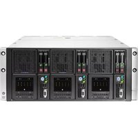


| Product Type | Server |
| Brand | HP |
| Model | ProLiant SL4540 G8 |
| Form Factor | 2U Rack |
| Dimensions (W x D x H) | 17.5 x 27.5 x 3.4 inches (44.5 x 69.9 x 8.7 cm) |
| Weight | Approximately 55 lbs (25 kg) fully loaded |
| Processor | Dual Intel Xeon E5-2600 v2 series (up to 12 cores each) |
| Memory | Up to 384 GB DDR3 ECC Registered (24 DIMM slots) |
| Storage | Up to 14 LFF SAS/SATA hot-swap drives or 28 SFF drives |
| Networking | Dual Gigabit Ethernet (integrated) plus optional 10GbE |
| Power Supply | Dual redundant hot-plug 750W or 1200W (up to 80 Plus Gold) |
| Expansion Slots | Up to 3 PCIe 3.0 slots |
| Management | HP iLO 4 with Intelligent Provisioning |
| Security | TPM 1.2/2.0, Secure Boot, BIOS lockdown |
| Cooling | Hot-plug redundant fans (N+1) |
| Maintenance | Tool-less access, hot-swap drives and power supplies |
| Spare Parts | Drive caddies, memory DIMMs, power supplies, fan modules |
| Operating Systems Supported | Windows Server, Red Hat, SUSE, VMware ESXi |
| Power Consumption (Typical) | 450-800W depending on configuration |
Frequently Asked Questions - ProLiant SL4540 G8 HP
User questions about ProLiant SL4540 G8 HP
0 question about this device. Answer the ones you know or ask your own.
Ask a new question about this device
Download the instructions for your Server in PDF format for free! Find your manual ProLiant SL4540 G8 - HP and take your electronic device back in hand. On this page are published all the documents necessary for the use of your device. ProLiant SL4540 G8 by HP.
USER MANUAL ProLiant SL4540 G8 HP
HP ProLiant SL4540 Gen8 Server Node Maintenance and Service Guide
Abstract
This guide describes identification and maintenance procedures, diagnostic tools, specifications for hardware components and software for the HP ProLiant SL4540 Gen8 Server Node. This guide is for an experienced service technician. HP assumes you are qualified in the servicing of computer equipment, trained in recognizing hazards in products, and are familiar with weight and stability precautions.

Part Number: 683990-003
February 2014
Edition: 3
© Copyright 2012, 2014 Hewlett-Packard Development Company, L.P.
The information contained herein is subject to change without notice. The only warranties for HP products and services are set forth in the express warranty statements accompanying such products and services. Nothing herein should be construed as constituting an additional warranty. HP shall not be liable for technical or editorial errors or omissions contained herein.
Microsoft® and Windows® are U.S. registered trademarks of Microsoft Corporation.
Intel® and Xeon® are registered trademarks of Intel Corporation in the U.S. and other countries.
Contents
Customer self repair 5
Parts only warranty service 5
Illustrated parts catalog 15
Mechanical components....15
System components 17
Removal and replacement procedures.... 22
Required tools....22
Preparation procedures....22
Power down the node 22
Remove a node from the chassis....23
Installing a node into the chassis 23
Remove the access panel 24
Install the access panel....24
Safety considerations 24
Preventing electrostatic discharge 24
Symbols on equipment 25
Server warnings and cautions 25
Drive blank 26
Drive 26
DIMMs....28
Heatsink 29
Processor 30
SFF backplane board....35
Front panel board 36
Personality board assembly 37
SUV interface board 38
System board 39
System battery 47
HP Trusted Platform Module 47
Troubleshooting 49
Troubleshooting resources 49
Diagnostic tools 50
HP ROM-Based Setup Utility 50
HP Insight Diagnostics....50
Integrated Management Log 50
HP Insight Remote Support software 51
Component identification....52
Front panel components 52
Front panel LEDs and buttons 52
Hot-plug drive LED definitions....53
System board components....54
DIMM slots 55
System maintenance switch....55
NMI jumper....55
Personality board components 56
Cabling 57
Personality board cabling....57
HDD data LED cabling 57
SATA cabling 58
Internal power cabling 58
RPS cabling 59
Front I/O cabling 59
SATA board power cabling 60
USB/VGA cabling....60
Specifications 61
Environmental specifications 61
Hot-plug power supply calculations....61
Acronyms and abbreviations....62
Documentation feedback 63
Index....64
Customer self repair
HP products are designed with many Customer Self Repair (CSR) parts to minimize repair time and allow for greater flexibility in performing defective parts replacement. If during the diagnosis period HP (or HP service providers or service partners) identifies that the repair can be accomplished by the use of a CSR part, HP will ship that part directly to you for replacement. There are two categories of CSR parts:
- Mandatory—Parts for which customer self repair is mandatory. If you request HP to replace these parts, you will be charged for the travel and labor costs of this service.
- Optional—Parts for which customer self repair is optional. These parts are also designed for customer self repair. If, however, you require that HP replace them for you, there may or may not be additional charges, depending on the type of warranty service designated for your product.
NOTE: Some HP parts are not designed for customer self repair. In order to satisfy the customer warranty, HP requires that an authorized service provider replace the part. These parts are identified as "No" in the Illustrated Parts Catalog.
Based on availability and where geography permits, CSR parts will be shipped for next business day delivery. Same day or four-hour delivery may be offered at an additional charge where geography permits. If assistance is required, you can call the HP Technical Support Center and a technician will help you over the telephone. HP specifies in the materials shipped with a replacement CSR part whether a defective part must be returned to HP. In cases where it is required to return the defective part to HP, you must ship the defective part back to HP within a defined period of time, normally five (5) business days. The defective part must be returned with the associated documentation in the provided shipping material. Failure to return the defective part may result in HP billing you for the replacement. With a customer self repair, HP will pay all shipping and part return costs and determine the courier/carrier to be used.
For more information about HP's Customer Self Repair program, contact your local service provider. For the North American program, refer to the HP website (http://www.hp.com/go/selfrepair).
Parts only warranty service
Your HP Limited Warranty may include a parts only warranty service. Under the terms of parts only warranty service, HP will provide replacement parts free of charge.
For parts only warranty service, CSR part replacement is mandatory. If you request HP to replace these parts, you will be charged for the travel and labor costs of this service.
Customer Self Repair
Customer Self Repair
Illustrated parts catalog
Mechanical components

| Item | Description | Spare part number | Customer self repair (on page 5) |
| 1 | Access panel | 691280-001 | Mandatory 1 |
| 2 | Drive blank, SFF | 670033-001 | Mandatory 1 |
| 3 | HP ProLiant SL4540 node — — |
Mandatory—Parts for which customer self repair is mandatory. If you request HP to replace these parts, you will be charged for the travel and labor costs of this service.
2 Optional—Parts for which customer self repair is optional. These parts are also designed for customer self repair. If, however, you require that HP replace them for you, there may or may not be additional charges, depending on the type of warranty service designated for your product.
3 No—Some HP parts are not designed for customer self repair. In order to satisfy the customer warranty, HP requires that an authorized service provider replace the part. These parts are identified as "No" in the Illustrated Parts Catalog.
| Item | Description Spare part | number | Customer self repair (on page 5) |
| 4 | System boards — — | ||
| a) System board | 687246-001 | Optional2 | |
| b) System board-IVB* | 755313-001 | Optional2 | |
| 5 | Hot-plug solid state SATA drives — — | ||
| a) 100-GB, SFF, MLC, 3G | 653965-001 | Mandatory1 | |
| b) 200-GB, SFF, MLC, 3G* | 653966-001 | Mandatory1 | |
| c) 400-GB, SFF, MLC, 3G* | 653967-001 | Mandatory1 | |
| d) 500-GB, SFF, MDL, 6G* | 656107-001 | Mandatory1 | |
| e) 1-TB, SFF, MDL, 6G* | 656108-001 | Mandatory1 | |
| Memory | |||
| 6 | DIMMs — — | ||
| a) 4-GB, PC3L-10600R-9, single-rank x4 | 664688-001 | Mandatory1 | |
| b) 8-GB, PC3L-10600R-9, dual-rank x4* | 664690-001 | Mandatory1 | |
| c) 16-GB, PC3L-10600R-9, dual-rank x4* | 664692-001 | Mandatory1 | |
| d) 8-GB, PC3L-12800R, single-rank x4* † | 735302-001 | Mandatory1 | |
| e) 16-GB, PCL3-12800R, IPL 1Gx4* † | 715284-001 | Mandatory1 | |
| f) 8-GB, PCL3-12800R, IPL 512Mx4* † | 715283-001 | Mandatory1 | |
| g) 4-GB, PCL3-12800R, IPL 512Mx4* † | 715282-001 | Mandatory1 | |
| h) 8-GB, PCL3-12800E, IPL 512Mx8* † | 715281-001 | Mandatory1 | |
| i) 2-GB, PCL3-12800E, IPL 256Mx8* † | 715279-001 | Mandatory1 | |
| j) 4-GB, PCL3-12800E, IPL 256Mx8* † | 715208-001 | Mandatory1 | |
| 7 | Heatsink | 689496-001 | Optional2 |
| 8 | Personality board assembly | 717703-001 | Optional2 |
| 9 | SUV interface board | 689237-001 | Mandatory1 |
| 10 | Processors | — — | |
| a) 2.3-GHz Intel Xeon E5-2470 processor** | 676943-001 | Optional2 | |
| b) 2.4GHz Intel Xeon E5-2440 processor* ** | 676945-001 | Optional2 | |
| c) 2.2-GHz Intel Xeon E5-2430 processor* ** | 676946-001 | Optional2 | |
| d) 2.2 GHz Intel Xeon E5-2407 processor* ** | 676948-001 | Optional2 | |
| e) 2.0 GHz Intel Xeon E5-2430L processor* ** | 676950-001 | Optional2 | |
| f) 2.4-GHz Intel Xeon E5-2470v2 processor* ** † | 729115-001 | Optional2 | |
| g) 2.50-GHz Intel Xeon E5-2450 v2 processor* ** † | 729114-001 | Optional2 | |
| h) 1.90-GHz Intel Xeon E5-2440 v2 processor* ** † | 729113-001 | Optional2 | |
| i) 2.50-GHz Intel Xeon E5-2430 v2 processor* ** † | 729112-001 | Optional2 | |
| j) 2.20-GHz Intel Xeon E5-2420 v2 processor* ** † | 729111-001 | Optional2 | |
| k) 2.40-GHz Intel Xeon E5-2407 v2 processor* ** † | 729110-001 | Optional2 | |
| l) 1.70-GHz Intel Xeon E5-2450L v2 processor* ** † | 729108-001 | Optional2 | |
| m) 2.40-GHz Intel Xeon E5-2430L v2 processor* ** † | 729107-001 | Optional2 | |
| 11 | SFF drive backplane board | 689231-001 | Mandatory1 |
| 12 | Front panel board | 689232-001 | Mandatory1 |
| Cables | — | — | |
| 13 | USB/VGA cable* | 694549-001 | Optional2 |
| 14 | RJ-45 personality board assembly cable* | 694548-001 | Mandatory1 |
| 15 | RPS cable* | 694547-001 | Mandatory1 |
| 16 | Internal node power (RPS, PWR, MSAR, RT) cable* | 694539-001 | Mandatory1 |
| 17 | HDD data LED (SFF I2C) cable* | 694546-001 | Optional2 |
| 18 | Front LED cable* | 694545-001 | Optional2 |
| 19 | SATA power converter cable* | 694543-001 | Mandatory1 |
| 20 | SATA power/data cable* | 694540-001 | Optional2 |
* Not Shown
**All processors in this HP ProLiant node must have the same cache size, speed, number of cores, and rated maximum power consumption.
† For use only with system board 755313-001.
1 Mandatory—Parts for which customer self repair is mandatory. If you request HP to replace these parts, you will be charged for the travel and labor costs of this service.
2 Optional—Parts for which customer self repair is optional. These parts are also designed for customer self repair. If, however, you require that HP replace them for you, there may or may not be additional charges, depending on the type of warranty service designated for your product.
3 No—Some HP parts are not designed for customer self repair. In order to satisfy the customer warranty, HP requires that an authorized service provider replace the part. These parts are identified as "No" in the Illustrated Parts Catalog.
1Mandatory: Obligatoire—Pièces pour lesquelles la réparation par le client est obligatoire. Si vous demandez à HP de remplacer ces pièces, les coûts de déplacement et main d'œuvre du service vous seront facturés.
2 Optional: Facultatif—Pièces pour lesquelles la réparation par le client est facultative. Ces pièces sont également conçues pour permettre au client d'effectuer lui-même la réparation. Toutefois, si vous demandez à HP de remplacer ces pièces, l'intervention peut ou non vous être facturée, selon le type de garantie applicable à votre produit.
3 No: Non—Certaines pièces HP ne sont pas conçues pour permettre au client d'effectuer lui-même la réparation. Pour que la garantie puisse s'appliquer, HP exige que le remplacement de la pièce soit effectué par un Mainteneur Agréé. Ces pièces sont identifiées par la mention "Non" dans le Catalogue illustré.
1 Mandatory: Obbligatorie—Parti che devono essere necessariamente riparate dal cliente. Se il cliente ne affida la riparazione ad HP, deve sostenere le spese di spedizione e di manodopera per il servizio.
2 Optional: Opzionali—Parti la cui riparazione da parte del cliente è facoltativa. Si tratta comunque di componenti progettati per questo scopo. Se tuttavia il cliente ne richiede la sostituzione ad HP, potrebbe dover sostenere spese addizionali a seconda del tipo di garanzia previsto per il prodotto.
3 No: Non CSR—Alcuni componenti HP non sono progettati per la riparazione da parte del cliente. Per rispettare la garanzia, HP richiede che queste parti siano sostituite da un centro di assistenza autorizzato. Tali parti sono identificate da un “No” nel Catalogo illustrato dei componenti.
1 Mandatory: Zwingend—Teile, die im Rahmen des Customer Self Repair Programms ersetzt werden müssen. Wenn Sie diese Teile von HP ersetzen lassen, werden Ihnen die Versand- und Arbeitskosten für diesen Service berechnet.
Removal and replacement procedures
Required tools
You need the following items for some procedures:
• T-10 Torx screwdriver
• T-15 Torx screwdriver
HP Insight Diagnostics software ("HP Insight Diagnostics" on page 50)
Preparation procedures
To access some components and perform certain service procedures, you must perform one or more of the following procedures:
• Power down the nodes ("Power down the node" on page 22).
If you must remove the chassis from a rack or a non-hot-plug component from the chassis or node, then you must power down the nodes.
- Remove the nodes from the chassis ("Remove a node from the chassis" on page 23).
If the rack environment, cabling configuration, or the chassis location in the rack creates unstable conditions, then remove the node from the chassis.
- Remove the access panel (on page 24).
• Install the access panel (on page 24).
Power down the node
Before powering down the node for any upgrade or maintenance procedures, perform a backup of critical server data and programs.

IMPORTANT: When the node is in standby mode, auxiliary power is still being provided to the system.
To power down the node, use one of the following methods:
- Press and release the Power On/Standby button.
This method initiates a controlled shutdown of applications and the OS before the node enters standby mode.
- Press and hold the Power On/Standby button for more than 4 seconds to force the node to enter standby mode.
This method forces the node to enter standby mode without properly exiting applications and the OS. If an application stops responding, you can use this method to force a shutdown.
• Use a virtual power button selection through iLO.
This method initiates a controlled remote shutdown of applications and the OS before the node enters standby mode.
Before proceeding, verify the node is in standby mode by observing that the system power LED is amber.
Remove a node from the chassis
- Power down the node (on page 22).

CAUTION: To avoid damage to the node, always support the bottom of the node when removing it from the chassis.
- Remove the node from the chassis:
a. Press the release button.
b. Lower the handle.
c. Remove the node.
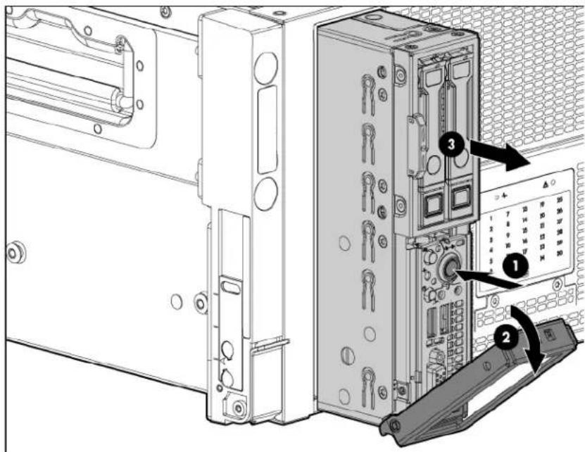

CAUTION: To avoid damage to the device, do not use the removal handle to carry it.
- Place the node on a flat, level surface.
Installing a node into the chassis
Install the component as indicated.

Remove the access panel
To remove the component:
- Power down the node (on page 22).
- Remove the node ("Remove a node from the chassis" on page 23).
-
Press the access panel release button.
-
Slide the access panel towards the rear of the node, and then lift to remove the panel.
Install the access panel
- Place the access panel on top of the node.
- Slide the access panel forward until it clicks into place.
Safety considerations
Before performing service procedures, review all the safety information.
Preventing electrostatic discharge
To prevent damaging the system, be aware of the precautions you need to follow when setting up the system or handling parts. A discharge of static electricity from a finger or other conductor may damage system boards or other static-sensitive devices. This type of damage may reduce the life expectancy of the device.
To prevent electrostatic damage:
- Avoid hand contact by transporting and storing products in static-safe containers.
- Keep electrostatic-sensitive parts in their containers until they arrive at static-free workstations.
- Place parts on a grounded surface before removing them from their containers.
- Avoid touching pins, leads, or circuitry.
• Always be properly grounded when touching a static-sensitive component or assembly.
Symbols on equipment
The following symbols may be placed on equipment to indicate the presence of potentially hazardous conditions.

This symbol indicates the presence of hazardous energy circuits or electric shock hazards. Refer all servicing to qualified personnel.
WARNING: To reduce the risk of injury from electric shock hazards, do not open this enclosure. Refer all maintenance, upgrades, and servicing to qualified personnel.

This symbol indicates the presence of electric shock hazards. The area contains no user or field serviceable parts. Do not open for any reason.
WARNING: To reduce the risk of injury from electric shock hazards, do not open this enclosure.

This symbol on an RJ-45 receptacle indicates a network interface connection.
WARNING: To reduce the risk of electric shock, fire, or damage to the equipment, do not plug telephone or telecommunications connectors into this receptacle.

This symbol indicates the presence of a hot surface or hot component. If this surface is contacted, the potential for injury exists.
WARNING: To reduce the risk of injury from a hot component, allow the surface to cool before touching.

This symbol indicates that the component exceeds the recommended weight for one individual to handle safely.
WARNING: To reduce the risk of personal injury or damage to the equipment, observe local occupational health and safety requirements and guidelines for manual material handling.

These symbols, on power supplies or systems, indicate that the equipment is supplied by multiple sources of power.
WARNING: To reduce the risk of injury from electric shock, remove all power cords to completely disconnect power from the system.
Server warnings and cautions
Before installing a server, be sure that you understand the following warnings and cautions.

WARNING: To reduce the risk of electric shock or damage to the equipment:
- Do not disable the power cord grounding plug. The grounding plug is an important safety feature.
- Plug the power cord into a grounded (earthed) electrical outlet that is easily accessible at all times.
- Unplug the power cord from the power supply to disconnect power to the equipment.
- Do not route the power cord where it can be walked on or pinched by items placed against it. Pay particular attention to the plug, electrical outlet, and the point where the cord extends from the server.
!
WARNING: To reduce the risk of personal injury from hot surfaces, allow the drives and the internal system components to cool before touching them.
△
CAUTION: Do not operate the node for long periods with the access panel open or removed. Operating the node in this manner results in improper airflow and improper cooling that can lead to thermal damage.
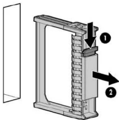
Drive blank
Remove the component as indicated.
△
CAUTION: To prevent improper cooling and thermal damage, do not operate the server unless all bays are populated with either a component or a blank.
To replace the component, slide the component into the bay until it clicks.
Drive
To remove the component:
-
Determine the status of the drive from the drive LED definitions ("Hot-plug drive LED definitions" on page 53).
-
Back up all data on the drive.
-
Remove the drive.
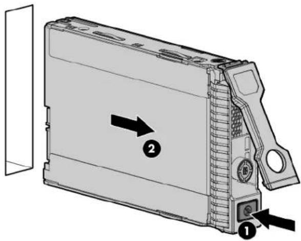
To replace the component:

CAUTION: To prevent improper cooling and thermal damage, do not operate the HP ProLiant SL4500 Series unless all drive and device bays are populated with either a component or a blank.
- Prepare the drive.

- Install the drive.

- Determine the status of the drive from the drive LED definitions ("Hot-plug drive LED definitions" on page 53).
DIMMs
To remove the component:
- Power down the node (on page 22).
- Remove the node from the chassis ("Remove a node from the chassis" on page 23).
- Remove the access panel (on page 24).
- Remove the DIMM.

To replace the component, reverse the removal procedure.
Heatsink
To remove the component:

CAUTION: The heatsink thermal interface media is not reusable and must be replaced if the heatsink is removed from the processor after it has been installed.
- Power down the node (on page 22).
- Remove the node from the chassis ("Remove a node from the chassis" on page 23).
- Remove the access panel (on page 24).
- Remove the heatsink.

To replace the component:
-
Use the alcohol swab to remove all the existing thermal grease from the processor. Allow the alcohol to evaporate before continuing.
-
Remove the thermal interface protective cover from the heatsink.


CAUTION: To avoid damage to the system board, processor socket, and screws, do not overtighten the heatsink screws. Use the wrench supplied with the system to reduce the possibility of overtightening the screws.
- Install the heatsink.

-
Install the access panel (on page 24).
-
Install the node into the chassis ("Installing a node into the chassis" on page 23).
-
Power up the node.
Processor
WARNING: To reduce the risk of personal injury from hot surfaces, allow the drives and the internal system components to cool before touching them.
CAUTION: To prevent possible node malfunction and damage to the equipment, multiprocessor configurations must contain processors with the same part number.
CAUTION: To avoid damage to the processor and system board, only authorized personnel should attempt to replace or install the processor in this node.
CAUTION: The heatsink thermal interface media is not reusable and must be replaced if the heatsink is removed from the processor after it has been installed.
IMPORTANT: Processor socket 1 must be populated at all times or the node does not function.
To remove the component:
- Power down the node (on page 22).
- Remove the node from the chassis ("Remove a node from the chassis" on page 23).
- Place the node on a flat, level work surface.
- Remove the access panel (on page 24).
- Remove the heatsink.


IMPORTANT: To avoid forcibly ejecting the processor, open the levers slowly.
- Open each of the processor locking levers in the order indicated, and then open the processor retaining bracket.

- Remove the processor from the processor retaining bracket.

△
CAUTION: To avoid damage to the processor, do not touch the bottom of the processor, especially the contact area.
- Install the processor. Verify that the processor is fully seated in the processor retaining bracket by visually inspecting the processor installation guides on either side of the processor. THE PINS ON THE SYSTEM BOARD ARE VERY FRAGILE AND EASILY DAMAGED.
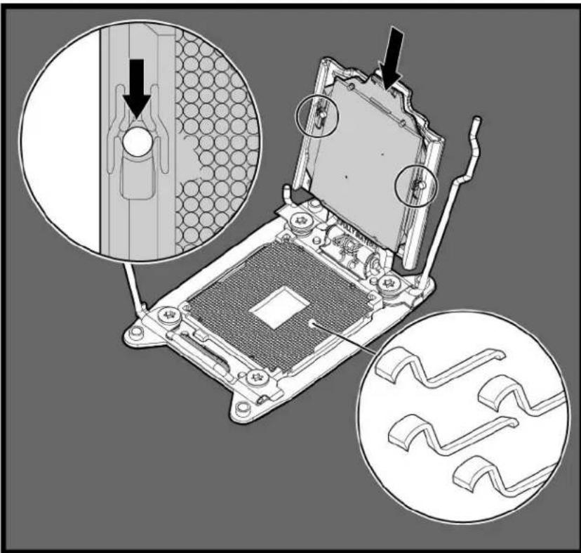

CAUTION: THE PINS ON THE SYSTEM BOARD ARE VERY FRAGILE AND EASILY DAMAGED. To avoid damage to the system board, do not touch the processor or the processor socket contacts.
- Close the processor retaining bracket. When the processor is installed properly inside the processor retaining bracket, the processor retaining bracket clears the flange on the front of the socket.

CAUTION: Do not press down on the processor. Pressing down on the processor may cause damage to the processor socket and the system board. Press only in the area indicated on the processor retaining bracket.
- Press and hold the processor retaining bracket in place, and then close each processor locking lever. Press only in the area indicated on the processor retaining bracket.

-
Use the alcohol swab to remove all the existing thermal grease from the heatsink. Allow the alcohol to evaporate before continuing.
-
Apply the thermal grease to the top of the processor in the following pattern.


CAUTION: To avoid damage to the system board, processor socket, and screws, do not overtighten the heatsink screws. Use the wrench supplied with the system to reduce the possibility of overtightening the screws.
- Install the heatsink.

- Install the access panel (on page 24).
- Install the node into the chassis ("Installing a node into the chassis" on page 23).
- Power up the server.
SFF backplane board
To remove the component:
- Power down the node (on page 22).
- Remove the node from the chassis ("Remove a node from the chassis" on page 23).
- Remove the access panel (on page 24).
- Disconnect all cables from the SFF backplane board.
-
Remove the two screws securing the board to the node.
-
Remove the board.

To replace the component, reverse the removal procedure.
Front panel board
To remove the component:
- Power down the node (on page 22).
- Remove the node from the chassis ("Remove a node from the chassis" on page 23).
- Remove the access panel (on page 24).
- Disconnect all cables from the front panel board.
- Remove the three screws securing the front panel board to the node.
- Remove the board.

To replace the component, reverse the removal procedure.
Personality board assembly
To remove the component:
- Power down the node (on page 22).
- Remove the node from the chassis ("Remove a node from the chassis" on page 23).
- Remove the access panel (on page 24).
- Disconnect all cables connected to the top of the personality board.

- Remove the screws securing the personality board assembly to the node.

CAUTION: Do not remove the four screws that secure the personality board to the bracket. Only remove the screws that secure the personality board assembly to the system board.

- Disconnect all cables connected to the underside of the personality board assembly.
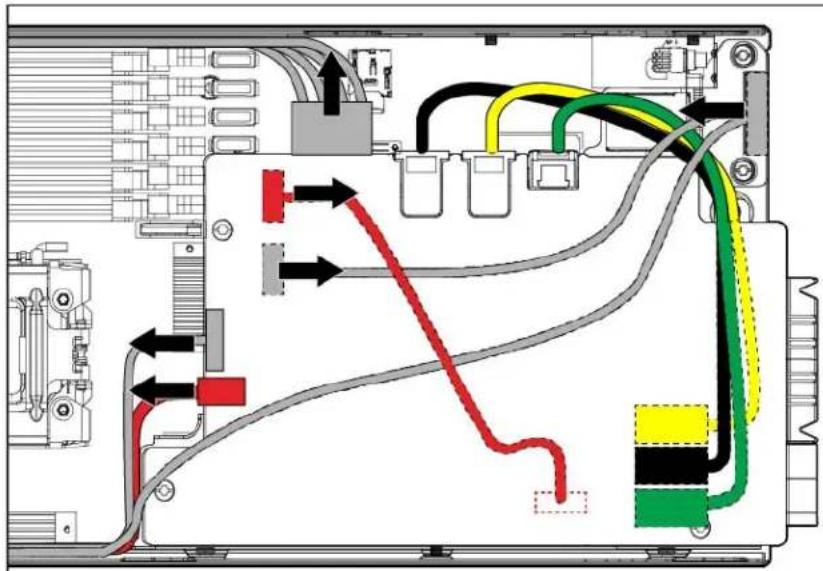
- Remove the personality board assembly.

To replace the component, reverse the removal procedure.
SUV interface board
To remove the component:
- Power down the node (on page 22).
- Remove the node from the chassis ("Remove a node from the chassis" on page 23).
- Remove the access panel (on page 24).
- Remove the two screws securing the board to the node.
-
Disconnect all cables.
-
Remove the board.

To replace the component, reverse the removal procedure.
System board
To remove the component:
- Power down the node (on page 22).
- Remove the node from the chassis ("Remove a node from the chassis" on page 23).
- Remove the access panel (on page 24).
- Remove all DIMMs ("DIMMs" on page 28).
- Remove all heatsinks.


CAUTION: The heatsink thermal interface media is not reusable and must be replaced if the heatsink is removed from the processor after it has been installed.

IMPORTANT: To avoid forcibly ejecting the processor, open the levers slowly.
- Open each of the processor locking levers in the order indicated, and then open the processor retaining bracket.

- Remove the processor from the processor retaining bracket.
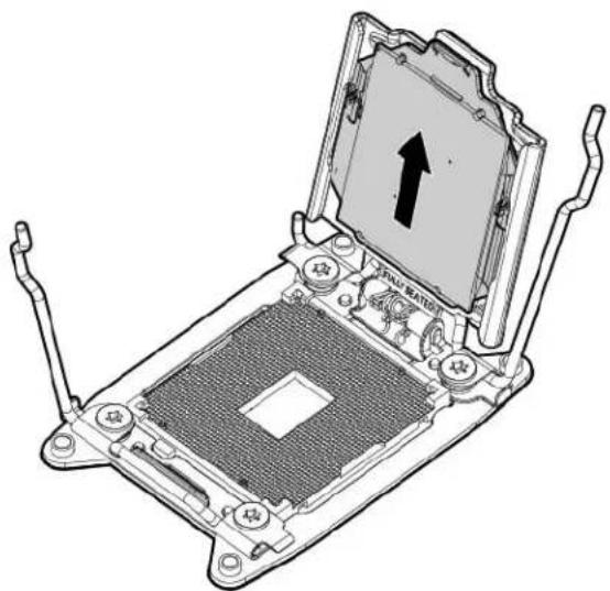

CAUTION: To avoid damage to the processor, do not touch the bottom of the processor, especially the contact area.
- Remove the personality board assembly (on page 37).
-
Remove the SUV interface board (on page 38).
-
Disconnect all cables from the system board.
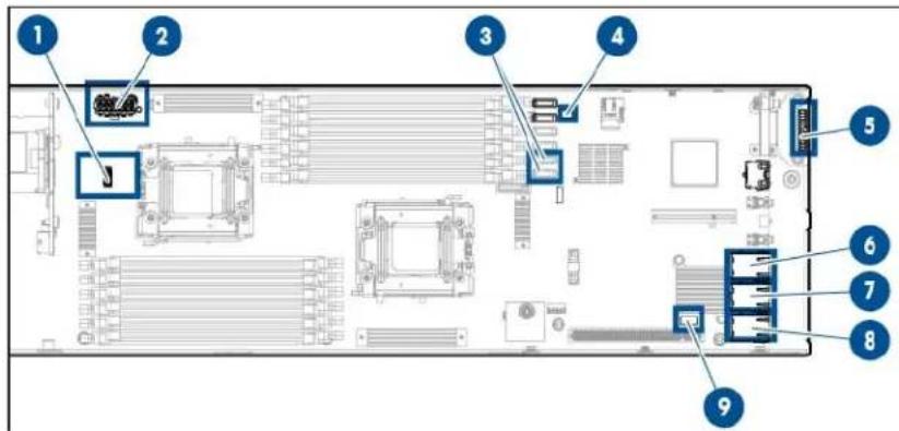
| Item Description | |
| 1 | RPS cable |
| 2 | Power cable |
| 3 | SATA cables |
| 4 | HDD data LED cable |
| 5 | SUV/VGA cable |
| 6 | NIC 1 cable |
| 7 | NIC 2 cable |
| 8 | iLO cable |
| 9 | LED cable |
- Remove the header cover.

- Remove the failed system board.

To replace the system board:
- Align the system board on the tray, and then install the header cover.
- Install the screws.

-
Connect all cables to the system board.
-
Open each of the processor locking levers in the order indicated, and then open the processor retaining bracket.

- Remove the clear processor socket cover. Retain the processor socket cover for future use.

- Install the processor. Verify that the processor is fully seated in the processor retaining bracket by visually inspecting the processor installation guides on either side of the processor. THE PINS ON THE SYSTEM BOARD ARE VERY FRAGILE AND EASILY DAMAGED.


CAUTION: THE PINS ON THE SYSTEM BOARD ARE VERY FRAGILE AND EASILY DAMAGED. To avoid damage to the system board, do not touch the processor or the processor socket contacts.
- Close the processor retaining bracket. When the processor is installed properly inside the processor retaining bracket, the processor retaining bracket clears the flange on the front of the socket.

CAUTION: Do not press down on the processor. Pressing down on the processor may cause damage to the processor socket and the system board. Press only in the area indicated on the processor retaining bracket.
- Press and hold the processor retaining bracket in place, and then close each processor locking lever. Press only in the area indicated on the processor retaining bracket.

-
Install the processor socket cover onto the processor socket of the failed system board.
-
Clean the old thermal grease from the heatsink and the top of the processor with the alcohol swab. Allow the alcohol to evaporate before continuing.
-
Apply all the grease to the top of the processor in the following pattern to ensure even distribution.


CAUTION: To avoid damage to the system board, processor socket, and screws, do not overtighten the heatsink screws. Use the wrench supplied with the system to reduce the possibility of overtightening the screws.
- Install the heatsink.

- Install the DIMMs (on page 28).
- Install the personality board assembly (on page 37).
- Install the SUV interface board (on page 38).
- Install the access panel (on page 24).
- Install the node into the chassis ("Installing a node into the chassis" on page 23).
- Power up the node.
After you replace the system board, you must re-enter the node serial number and the product ID.
- During the node startup sequence, press the F9 key to access RBSU.
- Select the Advanced Options menu.
- Select Service Options.
- Select Serial Number. The following warning appears:
Warning: The serial number should ONLY be modified by qualified service personnel. This value should always match the serial number located on the chassis.
- Press the Enter key to clear the warning.
- Enter the serial number and press the Enter key.
- Select Product ID. The following warning appears:
Warning: The Product ID should ONLY be modified by qualified service personnel. This value should always match the Product ID located on the chassis.
- Enter the product ID and press the Enter key.
- Press the Esc key to close the menu.
- Press the Esc key to exit RBSU.
- Press the F10 key to confirm exiting RBSU. The node automatically reboots.
System battery
If the node no longer automatically displays the correct date and time, you might have to replace the battery that provides power to the real-time clock. Under normal use, battery life is 5 to 10 years.

WARNING: The computer contains an internal lithium manganese dioxide, a vanadium pentoxide, or an alkaline battery pack. A risk of fire and burns exists if the battery pack is not properly handled. To reduce the risk of personal injury:
• Do not attempt to recharge the battery.
- Do not expose the battery to temperatures higher than 60°C (140°F).
- Do not disassemble, crush, puncture, short external contacts, or dispose of in fire or water.
- Replace only with the spare designated for this product.
To remove the component:
- Power down the node (on page 22).
- Remove the node from the chassis ("Remove a node from the chassis" on page 23).
- Remove the access panel (on page 24).
- Locate the battery on the system board ("System board components" on page 54).
- Remove the battery.


IMPORTANT: Replacing the system board battery resets the system ROM to its default configuration. After replacing the battery, reconfigure the system through RBSU.
To replace the component, reverse the removal procedure.
For more information about battery replacement or proper disposal, contact an authorized reseller or an authorized service provider.
HP Trusted Platform Module
The TPM is not a customer-removable part.

CAUTION: Any attempt to remove an installed TPM from the system board breaks or disfigures the TPM security rivet. Upon locating a broken or disfigured rivet on an installed TPM, administrators should consider the system compromised and take appropriate measures to ensure the integrity of the system data.
If you suspect a TPM board failure, leave the TPM installed and remove the system board ("System board" on page 39). Contact an HP authorized service provider for a replacement system board and TPM board.
Troubleshooting
Troubleshooting resources
The HP ProLiant Gen8 Troubleshooting Guide, Volume I: Troubleshooting provides procedures for resolving common problems and comprehensive courses of action for fault isolation and identification, issue resolution, and software maintenance on ProLiant servers and server blades. To view the guide, select a language:
• English (http://www.hp.com/support/ProLiant_TSG_v1_en)
French (http://www.hp.com/support/ProLiant_TSG_v1_fr)
• Spanish (http://www.hp.com/support/ProLiant_TSG_v1_sp)
• German (http://www.hp.com/support/ProLiant_TSG_v1_gr)
• Japanese (http://www.hp.com/support/ProLiant_TSG_v1_jp)
- Simplified Chinese (http://www.hp.com/support/ProLiant_TSG_v1_sc)
The HP ProLiant Gen8 Troubleshooting Guide, Volume II: Error Messages provides a list of error messages and information to assist with interpreting and resolving error messages on ProLiant servers and server blades. To view the guide, select a language:
• English (http://www.hp.com/support/ProLiant_EMG_v1_en)
French (http://www.hp.com/support/ProLiant_EMG_v1_fr)
• Spanish (http://www.hp.com/support/ProLiant_EMG_v1_sp)
• German (http://www.hp.com/support/ProLiant_EMG_v1_gr)
• Japanese (http://www.hp.com/support/ProLiant_EMG_v1_jp)
- Simplified Chinese (http://www.hp.com/support/ProLiant_EMG_v1_sc)
Diagnostic tools
HP ROM-Based Setup Utility
RBSU is a configuration utility embedded in HP ProLiant servers that performs a wide range of configuration activities that can include the following:
• Enabling and disabling system features
• Displaying system information
• Selecting the primary boot controller
- Configuring memory options
• Language selection
- Configuring system devices and installed options
For more information on RBSU, see the HP ROM-Based Setup Utility User Guide on the Documentation CD or the HP RBSU Information Library (http://www.hp.com/go/rbsu/docs).
HP Insight Diagnostics
HP Insight Diagnostics is a proactive node management tool, available in both offline and online versions, that provides diagnostics and troubleshooting capabilities to assist IT administrators who verify node installations, troubleshoot problems, and perform repair validation.
HP Insight Diagnostics Offline Edition performs various in-depth system and component testing while the OS is not running. To run this utility, boot the node using Intelligent Provisioning.
HP Insight Diagnostics Online Edition is a web-based application that captures system configuration and other related data needed for effective node management. Available in Microsoft Windows and Linux versions, the utility helps to ensure proper system operation.
For more information or to download the utility, see the HP website (http://www.hp.com/servers/diags). HP Insight Diagnostics Online Edition is also available in the SPP.
Integrated Management Log
The IML records hundreds of events and stores them in an easy-to-view form. The IML timestamps each event with 1-minute granularity.
You can view recorded events in the IML in several ways, including the following:
- From within HP SIM
• From within operating system-specific IML viewers - For Windows: IML Viewer
- For Linux: IML Viewer Application
• From within the iLO user interface
• From within HP Insight Diagnostics (on page 50)
HP Insight Remote Support software
HP strongly recommends that you register your device for remote support to enable enhanced delivery of your HP Warranty, HP Care Pack Service, or HP contractual support agreement. HP Insight Remote Support supplements your monitoring continuously to ensure maximum system availability by providing intelligent event diagnosis, and automatic, secure submission of hardware event notifications to HP, which will initiate a fast and accurate resolution, based on your product's service level. Notifications may be sent to your authorized HP Channel Partner for onsite service, if configured and available in your country.
For more information, see HP Insight Remote Support and Insight Online Setup Guide for ProLiant Gen8 Servers and BladeSystem c-Class Enclosures on the HP website (http://www.hp.com/go/enterprise/docs). HP Insight Remote Support is available as part of HP Warranty, HP Care Pack Service, or HP contractual support agreement.
Component identification
Front panel components

| Item Description | |
| 1 | Hard drive bay 1 |
| 2 | Hard drive bay 2 |
| 3 | Node release button |
| 4 | USB connectors (2) |
| 5 | VGA connector |
Front panel LEDs and buttons

| Item Description Status | ||
| 1 | UID LED button Blue = Activated | Flashing blue = System is being remotely managed or firmware update is in progress.Off = Deactivated |
| 2 | System Health LED Green = Normal | NormalFlashing amber = System degradedFlashing red = System critical |
| 3 | Power On/Standby button and system power LED | Green = System onAmber = System is in Standby mode, but power is still applied.Off = Power is not connected, or power supply has failed. |
Hot-plug drive LED definitions

| Item | LED | Status | Definition |
| 1 | Locate | Solid blue | The drive is being identified by a host application. |
| Flashing blue | The drive carrier firmware is being updated or requires an update. | ||
| 2 | Activity ring | Rotating green | Drive activity |
| Off No drive activity | |||
| 3 | Do not remove | Solid white | Do not remove the drive. Removing the drive causes one or more of the logical drives to fail. |
| Off | Removing the drive does not cause a logical drive to fail. | ||
| 4 | Drive status | Solid green | The drive is a member of one or more logical drives. |
| Flashing green | The drive is rebuilding or performing a RAID migration, strip size migration, capacity expansion, or logical drive extension, or is erasing. | ||
| Flashing amber/green | The drive is a member of one or more logical drives and predicts the drive will fail. | ||
| Flashing amber | The drive is not configured and predicts the drive will fail. | ||
| Solid amber | The drive has failed. | ||
| Off | The drive is not configured by a RAID controller. | ||
System board components

| Item Description | |
| 1 | HDD data LED backplane connector |
| 2 | Power connector |
| 3 | Processor socket 2 |
| 4 | Processor 1 DIMM slots (6) |
| 5 | SATA HDD connector 1 |
| 6 | SATA HDD connector 2 |
| 7 | Reserved connector |
| 8 | Reserved connector |
| 9 | Reserved connector |
| 10 | Reserved connector |
| 11 | HDD data LED connector |
| 12 | MicroSD card slot |
| 13 | USB/VGA connector |
| 14 | Personality board connector 1 |
| 15 | NMI jumper |
| 16 | NIC 1 connector |
| 17 | NIC 2 connector |
| 18 | iLO connector |
| 19 | LED power connector |
| 20 | Personality board connector 2 |
| 21 | System maintenance switch |
| 22 | Internal USB connector |
| 23 | TPM connector |
| 24 | System battery |
| 25 | Processor socket 1 |
| 26 | Processor 2 DIMM slots (6) |
| 27 | RPS connector |
| 28 | SFF backplane power connector |
| 29 | SATA connectors (2) |
| 30 | Front panel USB/VGA connector |
| 31 | VGA connector |
| 32 | Front LED connector |
DIMM slots
DIMM slots are numbered sequentially (1 through 6) for each processor. The supported AMP modes use the letter assignments for population guidelines.
![graph TD subgraph P1 A1["A"] --> 1["1"] A2["D"] --> 2["2"] A3["B"] --> 3["3"] A4["E"] --> 4["4"] A5["C"] --> 5["5"] A6["F"] --> 6["6"] end subgraph P2 B1["A"] --> 1 B2["D"] --> 2 B3["B"] --> 3 B4["E"] --> 4 B5["C"] --> 5 B6["F"] --> 6 end Ch1["Ch1"] --> D1["D"] Ch2["Ch2"] --> E1["E"] Ch3["Ch3"] -->…](/content/2026/07/1509857/images/0e512349fa38a65caf13a0cb7dbdabbb951ebcfd7ca4aa967868c261d4afe784.jpg)
System maintenance switch
| Position Default Function | ||
| S1 | Off | Off = iLO security enabledOn = iLO security disabled |
| S2 | Off | Off = System configuration unlockedOn = System configuration locked |
| S3 | Off Reserved | |
| S4 | Off Reserved | |
| S5 | Off | Off = Power-on password enabledOn = Power-on password disabled |
| S6 | Off Off = No functionOn = Clear NVRAM | |
| S7 | Off Reserved | |
| S8 | Off Reserved | |
| S9 | Off Reserved | |
| S10 | Off | Reserved |
When the system maintenance switch position 6 is set to the On position, the system is prepared to erase all system configuration settings from both CMOS and NVRAM.

CAUTION: Clearing CMOS and/or NVRAM deletes configuration information. Be sure to properly configure the server or data loss could occur.
NMI jumper
The NMI jumper allows administrators to perform a memory dump before performing a hard reset. Crash dump analysis is an essential part of eliminating reliability problems, such as hangs or crashes in OSs, device
drivers, and applications. Many crashes can freeze a system, requiring you to do a hard reset. Resetting the system erases any information that would support root cause analysis.
Systems running Microsoft® Windows® experience a blue-screen trap when the OS crashes. When this happens, Microsoft® recommends that system administrators perform an NMI event by temporarily shorting the NMI header with a jumper. The NMI event enables a hung system to become responsive again.
Personality board components
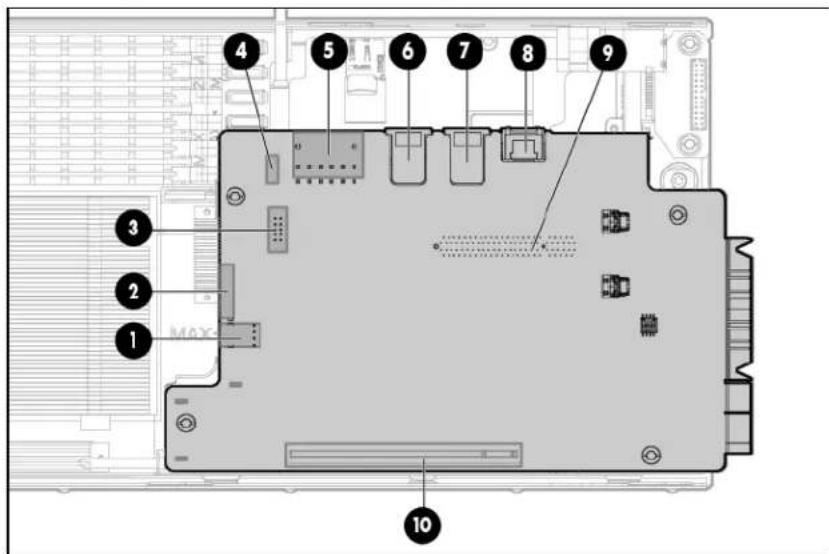
| Item Description | |
| 1 | Drive power connector |
| 2 | RPS connector |
| 3 | Serial connector* |
| 4 | LED cable connector* |
| 5 | Power connector |
| 6 | NIC 2 connector |
| 7 | NIC 1 connector |
| 8 | iLO connector |
| 9 | x8 personality board connector |
| 10 | x16 personality board connector |
* This connector is underneath the board.
Cabling
Personality board cabling
To access cables underneath the personality board assembly, see "Personality board assembly (on page 37)."

| Item Description | |
| 1 | NIC 2 (1 Gb) |
| 2 | NIC 1 (1 Gb) |
| 3 | iLO |
HDD data LED cabling

The HDD data LED cable routes underneath the SATA cables and power cable.
Connect and route the cables in the following order:
- HDD data LED cable (bottom)
- SATA cables
- Power cable
SATA cabling
To access cables underneath the personality board assembly, see "Personality board assembly (on page 37)."

The SATA cables route over the HDD data LED cable and underneath the power cable.
Connect and route the cables in the following order:
- HDD data LED cable (bottom)
- SATA cables
- Power cable
Internal power cabling

The power cable routes over the HDD LED cable and SATA cables.
Connect and route the cables in the following order:
- HDD data LED cable (bottom)
- SATA cables
- Power cable
RPS cabling

The RPS cable routes with the front LED cable underneath the SATA board power cable and USB/VGA cable.
Connect and route the cables in the following order:
- SATA power board cable
-
USB/VGA cable
-
RPS cable and front LED cable (bottom)
Front I/O cabling
To access cables underneath the personality board assembly, see "Personality board assembly (on page 37)."
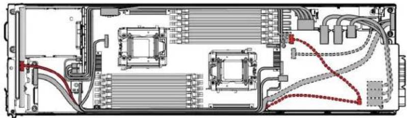
The front LED cable routes with the RPS cable underneath the SATA board power cable and the USB/VGA connector cable.
Connect and route the cables in the following order:
- RPS cable and front LED cable (bottom)
- SATA power board cable
- USB/VGA cable
SATA board power cabling

The SATA board power cable routes on top of the RPS cable and front LED cable, and underneath the USB/VGA cable. Secure the SATA board power cable in the plastic clip provided.
Connect and route the cables in the following order:
- RPS cable and front LED cable (bottom)
- SATA power board cable, secured in the plastic clip
- USB/VGA cable
USB/VGA cabling
To access cables underneath the personality board assembly, see "Personality board assembly (on page 37)."

The USB/VGA cable routes on top of the SATA board power cable, RPS cable, and front LED cable.
Connect and route the cables in the following order:
- RPS cable and front LED cable (bottom)
- SATA power board cable
- USB/VGA cable
Specifications
Environmental specifications
| Specification Value | |
| Temperature range* | |
| Operating | 10°C to 35°C (50°F to 95°F) |
| Shipping | -40°C to 70°C (-40°F to 158°F) |
| Maximum wet bulb temperature | 28°C (82.4°F) |
| Relative humidity (noncondensing)** | |
| Operating | 10% to 90% |
| Nonoperating | 5% to 95% |
* All temperature ratings shown are for sea level. An altitude derating of 1° C per 300 m (1.8°F per 1,000 ft) to 3,048 m (10,000 ft) is applicable. No direct sunlight allowed.
** Storage maximum humidity of 95% is based on a maximum temperature of 45°C (113°F). Altitude maximum for storage corresponds to a pressure minimum of 70 kPa.
Hot-plug power supply calculations
For hot-plug power supply specifications and calculators to determine electrical and heat loading for the server, see the HP Power Advisor website (http://www.hp.com/go/hppoweradvisor).
Acronyms and abbreviations
CSR
Customer Self Repair
NMI
nonmaskable interrupt
RPS
redundant power supply
SUV
serial, USB, video
Documentation feedback
HP is committed to providing documentation that meets your needs. To help us improve the documentation, send any errors, suggestions, or comments to Documentation Feedback (mailto:docsfeedback@hp.com). Include the document title and part number, version number, or the URL when submitting your feedback.
Index
A
access panel 24
B
backplane board 35
batteries, replacing 47
battery 47
buttons 22, 52
C
cables 57
cabling 57, 58, 59, 60
cabling, front I/O 59
cabling, internal power 58
cabling, personality board 57
cabling, RPS 59
cabling, SATA 58
cabling, SATA board power 60
cabling, USB 60
cabling, VGA 60
Care Pack 51
cautions 25
chassis, installing server 23
chassis, removing server 23
components 15, 52
components, identification 15, 52, 54, 56
components, mechanical 15
components, personality board 56
components, system board 54, 55
connectors 52
D
diagnosing problems 49
diagnostic tools 50
diagnostics utility 50
DIMMs 28, 55
drive blank 26
drive LEDs 53
drive, replacing 26
drives 26,53
drives, removing 26
E
electrostatic discharge 24
environmental requirements 61
environmental specifications 61
F
features 52
front I/O cabling 59
front LED cabling 59
front panel board 36
front panel components 52
front panel LEDs 52
H
heatsink 29
hot-plug power supply calculations 61
HP Insight Diagnostics 50
HP Insight Remote Support software 51
|
illustrated parts catalog 15
iLO (Integrated Lights-Out) 50
IML (Integrated Management Log) 50
Insight Diagnostics 50
installing the access panel 24
Integrated Lights-Out (iLO) 50
Integrated Management Log (IML) 50
L
LED cable 57
LEDs 53
LEDs, drive 53
LEDs, front panel 52, 53
LEDs, hard drive 53
LEDs, SAS hard drive 53
LEDs, troubleshooting 49
M
management tools 50
mechanical components 15
N
NMI header 55
P
personality board 37, 57
personality board cabling 57
personality board components 56
power cabling, internal 58
powering down 22
preparation procedures 22
problem diagnosis 49
processor 30
R
RBSU (ROM-Based Setup Utility) 50
removal and replacement procedures 22
removing the access panel 24
replacement procedures 22
required tools 22
ROM-Based Setup Utility (RBSU) 50
RPS cabling 59
s
safety considerations 24
safety information 24, 25
SAS drives 15, 53
SATA board power cabling 60
SATA cabling 58
server, installation 23
SFF backplane board 35
specifications 61
specifications, environmental 61
static electricity 24
SUV interface board 38
switch, system maintenance 55
symbols on equipment 25
system battery 47
system board components 54
system board replacement 39
system components 17, 52
system maintenance switch 55
T
technical support 5
temperature requirements 61
tools 22
Torx screwdriver 22
TPM (Trusted Platform Module) 47
troubleshooting 49
troubleshooting resources 49
Trusted Platform Module (TPM) 47
U
USB cabling 60
utilities 50
utilities, deployment 50
V
VGA cabling 60
W
warnings 25
weight 61
- HP PROLIANT SL4540 GEN8 SERVER NODE MAINTENANCE AND SERVICE GUIDE
- ABSTRACT
- CONTENTS
- CUSTOMER SELF REPAIR
- ILLUSTRATED PARTS CATALOG
- REMOVAL AND REPLACEMENT PROCEDURES
- TROUBLESHOOTING
- DIAGNOSTIC TOOLS
- COMPONENT IDENTIFICATION
- CABLING
- SPECIFICATIONS
- ACRONYMS AND ABBREVIATIONS
- DOCUMENTATION FEEDBACK
- INDEX
- PARTS ONLY WARRANTY SERVICE
- MECHANICAL COMPONENTS
- REQUIRED TOOLS
- PREPARATION PROCEDURES
- POWER DOWN THE NODE
- REMOVE A NODE FROM THE CHASSIS
- INSTALLING A NODE INTO THE CHASSIS
- REMOVE THE ACCESS PANEL
- INSTALL THE ACCESS PANEL
- SAFETY CONSIDERATIONS
- PREVENTING ELECTROSTATIC DISCHARGE
- SYMBOLS ON EQUIPMENT
- SERVER WARNINGS AND CAUTIONS
- DRIVE BLANK
- DRIVE
- DIMMS
- HEATSINK
- PROCESSOR
- SFF BACKPLANE BOARD
- FRONT PANEL BOARD
- PERSONALITY BOARD ASSEMBLY
- SUV INTERFACE BOARD
- SYSTEM BOARD
- SYSTEM BATTERY
- HP TRUSTED PLATFORM MODULE
- TROUBLESHOOTING RESOURCES
- HP ROM-BASED SETUP UTILITY
- HP INSIGHT DIAGNOSTICS
- INTEGRATED MANAGEMENT LOG
- HP INSIGHT REMOTE SUPPORT SOFTWARE
- FRONT PANEL COMPONENTS
- FRONT PANEL LEDS AND BUTTONS
- HOT-PLUG DRIVE LED DEFINITIONS
- SYSTEM BOARD COMPONENTS
- DIMM SLOTS
- SYSTEM MAINTENANCE SWITCH
- NMI JUMPER
- PERSONALITY BOARD COMPONENTS
- PERSONALITY BOARD CABLING
- HDD DATA LED CABLING
- SATA CABLING
- INTERNAL POWER CABLING
- RPS CABLING
- FRONT I/O CABLING
- SATA BOARD POWER CABLING
- USB/VGA CABLING
- HOT-PLUG POWER SUPPLY CALCULATIONS
- A
- B
- C
- D
- E
- F
- H
- L
- M
- N
- P
- R
- S
- T
- U
- V
- W
Brand : HP
Model : ProLiant SL4540 G8
Category : Server