
DLA-VS3000 - Projector JVC - Free user manual and instructions
Find the device manual for free DLA-VS3000 JVC in PDF.
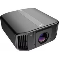


| Product Type | Video Projector |
| Brand | JVC |
| Model | DLA-VS3000 |
| Display Technology | D-ILA (0.69-inch) |
| Native Resolution | 3840 x 2160 (4K UHD) |
| Brightness | 2000 lumens |
| Contrast Ratio | 100,000:1 (native) |
| Lens Shift | Motorized, vertical ±80%, horizontal ±34% |
| Zoom | Motorized, 1.6x |
| Lamp Type | NSH 265W |
| Lamp Life | Up to 4000 hours (eco mode) |
| Dimensions (W x H x D) | 45.5 cm x 18.0 cm x 47.5 cm |
| Weight | 15.6 kg |
| Power Consumption | 400 W (max), 0.4 W (standby) |
| Supported HDR | HDR10, HLG |
| 3D Support | Yes (RF 3D glasses compatible) |
| Inputs | 2x HDMI 2.0, 1x Component, 1x Composite, 1x RS-232C, 1x LAN |
| Cleaning Instructions | Use a soft, dry cloth for lens; avoid solvents |
| Safety Features | Auto power-off, overheat protection |
| Spare Parts Available | Lamp model: PK-L2612U, filter: optional |
| Repairability Index | 7/10 |
| Warranty | 3 years (depending on region) |
Frequently Asked Questions - DLA-VS3000 JVC
User questions about DLA-VS3000 JVC
0 question about this device. Answer the ones you know or ask your own.
Ask a new question about this device
Download the instructions for your Projector in PDF format for free! Find your manual DLA-VS3000 - JVC and take your electronic device back in hand. On this page are published all the documents necessary for the use of your device. DLA-VS3000 by JVC.
USER MANUAL DLA-VS3000 JVC
For Customer use :
Enter below the serial No. which is located on the side of the cabinet. Retain this information for future reference.
DLA-VS3000GModel No.
Serial No.
Safety Precautions
IMPORTANT INFORMATION
WARNING:
TO PREVENT FIRE OR SHOCK HAZARDS, DO NOT EXPOSE THIS APPLIANCE TO RAIN OR MOISTURE.
WARNING:
THIS APPARATUS MUST BE EARTHED.
CAUTION:
To reduce the risk of electric shock, do not remove cover. Refer servicing to qualified service personnel.
This projector is equipped with a 3-blade grounding type plug to satisfy FCC rule. If you are unable to insert the plug into the outlet, contact your electrician.
NOISE EMISSION DECLARATION
The sound pressure level at the operator position is equal or less than 60dB(A) according to ISO7779.
WARNING
REMOVE THE LENS COVER BEFORE TURNING ON THE PROJECTOR
WARNING
This equipment is compliant with Class A of CISPR 32.
In residential environment this equipment may cause radio interference.
FCC INFORMATION (U.S.A. only)
CAUTION:
Changes or modification not approved by JVC could void the user's authority to operate the equipment.
NOTE:
This equipment has been tested and found to comply with the limits for a Class A digital device, pursuant to Part 15 of the FCC Rules. These limits are designed to provide reasonable protection against harmful interference when the equipment is operated in a commercial environment. This equipment generates, uses, and can radiate radio frequency energy and, if not installed and used in accordance with the instruction manual, may cause harmful interference to radio communications. Operation of this equipment in a residential area is likely to cause harmful interference in which case the user will be required to correct the interference at his own expense.
About the installation place
Do not install the projector in a place that cannot support its weight securely.
If the installation place is not sturdy enough, the projector could fall or overturn, possibly causing personal injury.
Supplier's Declaration of Conformity
Trad e Na m e: JVC
Products: D-ILA Projector
Model Name: DLA-VS3000G
Responsible Party: JVCKENWOOD USA Corporation
1440 Corporate Drive, Irving, TX 75038
Telephone number: 678-449-8879
This device complies with Part 15 of the FCC Rules. Operation is subject to the following two conditions;
(1) This device may not cause harmful interference, and
(2) This device must accept any interference received, including interference that may cause undesired operation.
IMPORTANT SAFEGUARDS
Electrical energy can perform many useful functions. This unit has been engineered and manufactured to assure your personal safety. But IMPROPER USE CAN RESULT IN POTENTIAL ELECTRICAL SHOCK OR FIRE HAZARD. In order not to defeat the safeguards incorporated into this product, observe the following basic rules for its installation, use and service. Please read these Important Safeguards carefully before use.
- All the safety and operating instructions should be read before the product is operated.
- The safety and operating instructions should be retained for future reference.
- All warnings on the product and in the operating instructions should be adhered to.
- All operating instructions should be followed.
- Place the projector near a wall outlet where the plug can be easily unplugged.
- Unplug this product from the wall outlet before cleaning.
- Do not use liquid cleaners or aerosol cleaners. Use a damp cloth for cleaning.
- Do not use attachments not recommended by the product manufacturer as they may be hazardous.
- Do not use this product near water. Do not use immediately after moving from a low temperature to high temperature, as this causes condensation, which may result in fire, electric shock, or other hazards.
- Do not place this product on an unstable cart, stand, or table. The product may fall, causing serious injury to a child or adult, and serious damage to the product. The product should be mounted according to the manufacturer's instructions, and should use a mount recommended by the manufacturer.
- When the product is used on a cart, care should be taken to avoid quick stops, excessive force, and uneven surfaces which may cause the product and cart to overturn, damaging equipment or causing possible injury to the operator.
- Slots and openings in the cabinet are provided for ventilation. These ensure reliable operation of the product and protect it from overheating. These openings must not be blocked or covered. (The openings should never be blocked by placing the product on bed, sofa, rug, or similar surface. It should not be placed in a built-in installation such as a bookcase or rack unless proper ventilation is provided and the manufacturer's instructions have been adhered to.)
- To allow better heat dissipation, keep a clearance between this unit and its surrounding as shown below. When this unit is enclosed in a space of dimensions as shown below, use an air-conditioner so that the internal and external temperatures are the same. Overheating can cause damage.
PORTABLE CART WARNING (symbol provided by RETAC)

S3126A

- Power source indicated on the label. If you are not sure of the type of power supply to your home, consult your product dealer or local power company.
- This product is equipped with a three-wire plug. This plug will fit only into a grounded power outlet. If you are unable to insert the plug into the outlet, contact your electrician to install the proper outlet. Do not defeat the safety purpose of the grounded plug.
- Power-supply cords should be routed so that they are not likely to be walked on or pinched by items placed upon or against them. Pay particular attention to cords at doors, plugs, receptacles, and the point where they exit from the product.
- For added protection of this product during a lightning storm, or when it is left unattended and unused for long periods of time, unplug it from the wall outlet and disconnect the cable system. This will prevent damage to the product due to lightning and power line surges.
- Do not overload wall outlets, extension cords, or convenience receptacles on other equipment as this can result in a risk of fire or electric shock.
- Never push objects of any kind into this product through openings as they may touch dangerous voltage points or short out parts that could result in a fire or electric shock. Never spill liquid of any kind on the product.
- Do not attempt to service this product yourself as opening or removing covers may expose you to dangerous voltages and other hazards. Refer all service to qualified service personnel.
- Unplug this product from the wall outlet and refer service to qualified service personnel under the following conditions:
a) When the power supply cord or plug is damaged.
b) If liquid has been spilled, or objects have fallen on the product.
c) If the product has been exposed to rain or water.
d) If the product does not operate normally by following the operating instructions. Adjust only those controls that are covered by the Operation Manual, as an improper adjustment of controls may result in damage and will often require extensive work by a qualified technician to restore the product to normal operation.
e) If the product has been dropped or damaged in any way.
f) When the product exhibits a distinct change in performance, this indicates a need for service.
- When replacement parts are required, be sure the service technician has used replacement parts specified by the manufacturer or with same characteristics as the original part. Unauthorized substitutions may result in fire, electric shock, or other hazards.
- Upon completion of any service or repairs to this product, ask the service technician to perform safety checks to determine that the product is in proper operating condition.
- The product should be placed more than one foot away from heat sources such as radiators, heat registers, stoves, and other products (including amplifiers) that produce heat.
- When connecting other products such as VCR's, and DVD players, you should turn off the power of this product for protection against electric shock.
- Do not place combustibles behind the cooling fan. For example, cloth, paper, matches, aerosol cans or gas lighters that present special hazards when over heated
- Do not ceiling-mount the projector to a place which tends to vibrate; otherwise, the attaching fixture of the projector could be broken by the vibration, possibly causing it to fall or overturn, which could lead to personal injury.
- Use only the accessory cord designed for this product to prevent shock.
- For health reasons, please take a break of about 5-15 minutes every 30-60 minutes and let your eyes rest. When using the devices with 3D function, please refrain from watching any 3D-images when you feel tired, unwell or if you feel any other discomfort. Moreover, in case you see a double image, please adjust the equipment and software for proper display. Please stop using the unit if the double
- image is still visible after adjustment. Once every three years, please perform an internal test. This unit is provided with replacement parts needed to maintain its function (such as cooling fans). Estimated replacement time of parts can vary greatly depending on frequency of use and the respective environment. For replacement, please consult your dealer, or the nearest
- authorized JVC service center. When fixing the unit to the ceiling, Please note that we do not take any responsibility, even during the warranty period, if the product is damaged due to use of metal fixtures used for fixation to the ceiling other than our own or if the installation environment of said metal fixtures is not appropriate. If the unit is suspended from the ceiling during use, please be careful in regard to the ambient temperature of the unit. If you use a central heating, the temperature
- close to the ceiling will be higher than normally expected. Video images can burn into the electronic component parts. Please do not display screens with still images of high brightness or high contrast, such as found in video games and computer programs. Over a long period of time it might stick to the picture element. There is no problem with the playback of moving images, e.g. normal video footage.
- Not using the unit for a long time can lead to malfunction. Please power it on and let it run occasionally. Please avoid using the unit in a room where cigarettes are smoked. It is impossible to clean optical component parts if they are contaminated by nicotine or tar. This might lead to performance degradation.
Pay attention to the following when using the devices with 3D function.
- Please watch from a distance three times the height of the projected image size. Persons with photosensitivity, any kind of heart disease, or weak health should not use 3D glasses.
- Watching 3D-images might be cause of illness. If you feel any change in your physical condition, please stop watching immediately and consult a physician if necessary.
- When watching 3D images, it is recommended to take regular breaks. As the length and frequency of the required breaks differ for every person, please judge according to your own condition.
- If your child watches while wearing 3D glasses, it should be accompanied by its parents or an adult guardian. The adult guardian should be careful to avoid situations where the child's eyes might become tired, as responses to tiredness and discomfort, etc., are hard to detect, and it is possible for the physical condition to deteriorate very quickly. As the visual sense is not yet fully developed in children under the age of 6, please consult a physician in regard to any problem concerning 3D-images if necessary.
- Note that when using the 3D feature, the video output may appear different from the original video image due to image conversion on the device.
* DO NOT allow any unqualified person to install the unit.
Be sure to ask your dealer to install the unit (e.g. attaching it to the ceiling) since special technical knowledge and skills are required for installation. If installation is performed by an unqualified person, it may cause personal injury or electrical shock.
- Do not use optical instruments (such as magnifying glass or reflector) viewing the laser output. It may pose an eye hazard.
- When turning on the projector, ensure that no one is looking into the projection lens.
- Do not look into the lens and openings when the light is on. Doing so would have serious effects on the human body.
- Do not detach or attach the projection lens with the power connected.
- Attempting to disassemble, repair or modify the projector yourself may lead to serious safety issues.
- Using a faulty product not only results in electrical shock or fire hazard, it can cause visual impairment.
- When abnormality occur, stop using the projector immediately and send it to your authorized dealer for repair.
POWER CONNECTION
For USA and Canada only
Use only the following power cord.
Power cord

The power supply voltage rating of this product is AC100V – AC240V. Use only the power cord designated by our dealer to ensure Safety and EMC. Ensure that the power cable used for the projector is the correct type for the AC outlet in your country. Consult your product dealer.
Power cord

For European continent countries
WARNING:
Do not cut off the main plug from this equipment.
If the plug fitted is not suitable for the power points in your home or the cable is too short to reach a power point, then obtain an appropriate safety approved extension lead or adapter or consult your dealer. If nonetheless the mains plug is cut off, dispose of the plug immediately, to avoid a possible shock hazard by inadvertent connection to the main supply.
WARNING:
THIS APPARATUS MUST BE EARTHED.
Dear Customer,
This apparatus is in conformance with the valid European directives and standards regarding electromagnetic compatibility and electrical safety. European representative of JVCKENWOOD Corporation is: JVCKENWOOD Deutschland GmbH Konrad-Adenauer-Allee 1-11, 61118 Bad Vilbel, GERMANY
IMPORTANT (Europe only):
The wires in the mains lead on this product are colored in accordance with the following cord:
Green-and-yellow : Earth
Blue : Neutral
Brown : Live
As these colors may not correspond with the colored making identifying the terminals in your plug, proceed as follows:
The wire which is colored green-and-yellow must be connected to the terminal which is marked M with the letter E or the safety earth or colored green or green-and-yellow. The wire which is colored blue must be connected to the terminal which is marked with the letter N or colored black.
The wire which is colored brown must be connected to the terminal which is marked with the letter L or colored red.
ENGLISH
Information for Users on Disposal of Old Equipment and Batteries


Products

Battery
[European Union only]
These symbols indicate that equipment with these symbols should not be disposed of as general household waste. If you want to dispose of the product or battery, please consider the collection systems or facilities for appropriate recycling.
Notice: The sign Pb below the symbol for batteries indicates that this battery contains lead.
FRANÇAIS
Location information of the mark

As with any bright light source, do not stare into the beam, RG2 IEC 62471-5:2015
For the customers In the U.S.A. and Canada
CAUTION
Use of controls or adjustments or performance of procedures other than those specified herein may result in hazardous radiation exposure.
This Projector is classified as a CLASS 2 LASER PRODUCT.
This CLASS 2 LASER PRODUCT label and Caution label is located on the right side surface of the projector.

Location information of the labels

WARNING
LASER RADIATION
DO NOT STARE INTO THE BEAM CLASS 2 LASER PRODUCT
CAUTION
Do not look into the lens while in use.
Light source specifications
95 W Laser diodes ×1
Wavelength 455 nm
Maximum output is 95 W
Beam divergence angle from lens of this unit
Wide: α = 71°
Tele: α = 39°

For the customers In other countries
CLASS 1 LASER PRODUCT
LASER CAUTION LABEL

WARNING
Do not look into the lens while in use.
CAUTION
Use of controls or adjustments or performance of procedures other than those specified herein may result in hazardous radiation exposure.
Location information of the labels

When used in China, the power cord is sold separately. A suitable power cord for this equipment is 10 A/250 V rated. Please do not use bundled power cords.
Safety Precautions 2
Accessories/Optional Accessories 13
Check the Accessories 13
Controls and Features 14
Main Unit - Front 14
Main Unit - Bottom 14
Main Unit - Rear 15
Main Unit - Input Terminals 16
Remote Control 17
Loading Batteries into the Remote Control ..... 18
Effective Range of Remote Control Unit 18
Menu 19
Set up
Installing the Projector 20
Precautions during Installation 20
Precautions during Mounting 21
Adjusting the Position 22
Connecting the Projector 23
Connecting to the DisplayPort Terminals ..... 23
Connecting to the LAN Terminal 23
Connecting to the RS-232C Terminal 24
Connecting to the REMOTE Terminal 24
Connecting the Power Cord (Supplied Accessory) ..... 24
Operate
Viewing Videos 25
Adjust/Set
Adjustments and Settings in the Menu 27
List of Menu Items 27

Picture Adjust 29

Input Signal 34

Installation 35

Display Setup 44

Function 45

Information 47
Maintenance
Maintaining the Cabinet and Remote Control ..... 48
Cleaning and Replacing the Filter 48
Long term storage of projector 49
About the Lens 50
Mounting the Lens 50
Troubleshooting
Troubleshooting 54
When the Following Messages Appear... 56
Others
External Control 57
RS-232C Specifications 57
TCP/IP Connection 57
Command Format 58
Remote Control Code 59
Communications Example 60
Specifications 61
Index 70
Accessories/Optional Accessories
Check the Accessories
Remote control 1 piece
AAA-size batteries (for operational check) 2 pieces
Power cord (for USA) (about. 2 m) .... 1 piece
Power cord (for EU) (about 2 m) .... 1 piece
Lens spacer .... 1 piece
Screw 4 pieces
Sponge .... 1 piece
Front base 1 piece

- Other items include the instruction manual, warranty, and other printed materials.
- Be sure to read the "Safety Precautions" before using this projector.
Controls and Features
Main Unit - Front
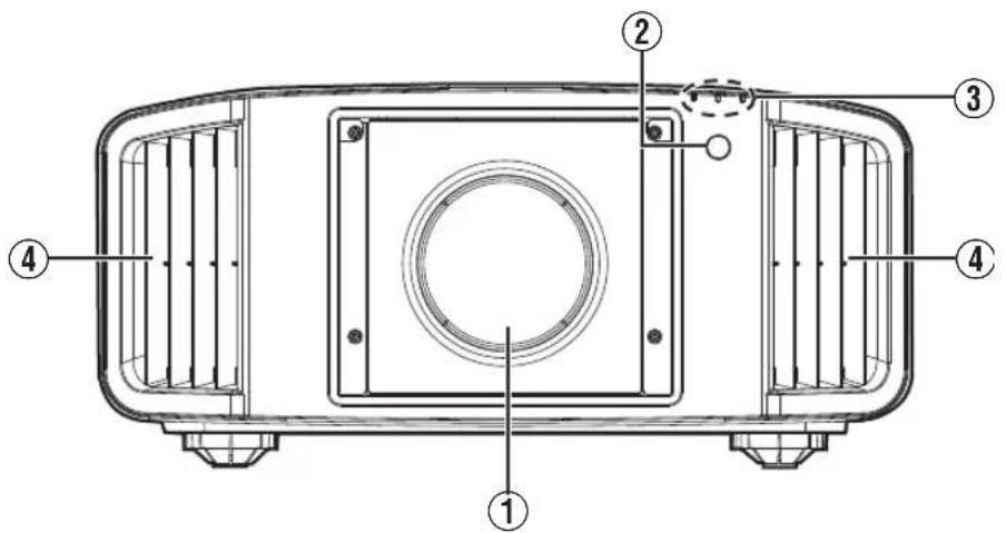
① Lens (sold separately)
Zoom lens or short focal length lens is optional.
② Remote Sensor (front)
Please aim the remote control at this area when using it.
* There is also a remote sensor at the rear.
③ Indicator
Refer to "Indicator Display on the Main Unit" P. 67.
④ Exhaust vent
Warm air is discharged to cool down the internal temperature.
Do not block the vents.
Main Unit - Bottom
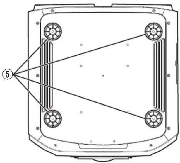
⑤ Feet
The height and angle of the projector can be adjusted by turning the foot. (0 to 5 mm) (P. 22)
When the foot is removed, it can be used as the mounting hole for the ceiling mount bracket.
Main Unit - Rear

⑥ Input terminals
For details on the terminals, refer to "Main Unit - Input Terminals" P. 16.
⑦ Operation panel
For more details, please refer to the "Operation panel" in the diagram below.
⑧ Remote Sensor (rear)
Please aim the remote control at this area when using it.
* There is also a remote sensor at the front.
⑨ Power input terminal
Connect the supplied power cord to this terminal.
⑩ Air Inlets
The inlets take in air to cool down the internal temperature.
Do not block the inlet. Do not blow hot air on the inlet. Doing so may cause the unit to malfunction.
Operation panel
![[▲ INPUT ▼]: Switches the input ○/I: Turns "on"/"off" the power [MENU]: Displays the menu △ INPUT ▼ OK BACK [BACK]: Returns to the previous menu [OK]: Confirms a selection [▲▼◀▶] keys: Selects an item](/content/2026/07/1508159/images/cc50dedfea8da983f4c0dcc2319e93f0906855f76426c909c9a31ecae1f052c5.jpg)
Main Unit - Input Terminals
Enlarged View of Rear Face

① [SYNC OUT] terminal
For synchronizing with other equipment.
② [DisplayPort 1] input terminal
③ [DisplayPort 2] input terminal (20-pin male)
For connecting to devices that support DisplayPort output. (P. 23)
④ [RS-232C] terminal (D-sub 9-pin male)
The projector can be controlled by connecting a PC to this terminal.
⑤ [SERVICE] terminal
For updating the software using a commercially available USB flash drive.
⑥ [LAN] terminal (RJ-45)
The projector can be controlled by connecting it to a PC through the computer network for control commands to be sent to the projector.
⑦ [REMOTE CONTROL] terminal (stereo mini jack)
This terminal is used to connect the remote control directly to the projector with the cable.
Remote Control

① ⏻ [STANDBY]
Turns off the power. (P. 26)
② I [ON]
Turns on the power. (P. 25)
③ [INPUT]
Switches the input.
- Pressing the button each time switches the setting in the following sequence: "DisplayPort 1" → "DisplayPort 2" → "Dual"...(P. 25)
④ [SETTING MEMORY]
Not usable on this unit.
⑤ [LENS CONTROL]
For adjusting focus, zoom, and shift. (P. 35)
- Pressing the button each time switches the setting in the following sequence: "Focus" → "Zoom" → "Shift"...
⑥ [HIDE]
Hides the image temporarily. (P. 25)
⑦ [INFO.]
Displays the information menu. (P. 47)
⑧ [▲▼◀▶] keys
For selecting an item.
⑨ [OK]
Confirms a selected item.
⑩ [MENU]
Displays the menu, or hides the menu if it is displayed.
⑪ [BACK]
Returns to the previous menu.
⑫ [PICTURE MODE]
Switches the picture mode. (P. 29)
⑬ [COLOR PROFILE]
Not usable on this unit.
⑭ [GAMMA SETTINGS]
Displays the gamma setting menu.
⑮ [C.M.D.]
Displays the frame interpolation selection menu.
⑯ [MPC]
Not usable on this unit.
⑰ [ADVANCED MENU]
Switches the "Adjust Area" when "Pixel Adjust" is used.
⑱ [LIGHT]
Illuminates the buttons on the remote control.
Loading Batteries into the Remote Control
Loading the batteries

- If the remote control has to be brought closer to the unit to operate, it means that the batteries are wearing out. Replace the batteries with new ones (AAA).
- Insert the batteries according to the marks. Be sure to insert the end first. When removing the battery, do so from the end.
- If an error occurs while using the remote control, remove the batteries and wait for five minutes. Load the batteries again and operate the remote control.
Removing the batteries

Effective Range of Remote Control Unit
When aiming the remote control toward the sensor on this unit (front or rear), ensure that the distance to the sensor is within 7 m.
If the remote control fails to work properly, move closer to this unit.

Control through reflection off a screen, etc.
Ensure that the total of distance A (between this unit and the screen) and distance B (between the remote control and the screen) is within 7 m.
* As the efficiency of signals reflected from the remote control unit varies with the type of screen used, the operable distance may decrease.

CAUTION
- Do not put the remote control in a place with an exposure to direct sun light or high temperature. It may deformed due to heat, or the internal components may be adversely affected resulting in fire hazard.
- Remove the batteries from the remote control when storing the remote control. Storing the remote control for a prolonged period without removing the batteries can cause battery leakage.
Menu

Select the icon at the top of the menu to display its corresponding setting item as shown below.
① Picture Adjust

② Input Signal

③ Installation

④ Display Setup

⑤ Function

⑥ Information
Installing the Projector
Precautions during Installation
Please read the following carefully before installing this unit.
When carrying this unit
This unit is heavy in weight. Please ensure that there are at least two persons carrying it.
Do not install at the following
This unit is a precision device. Please refrain from installing or using it at the following locations. Otherwise, it may cause fire or malfunction.
• Dusty, wet and humid places
- Places subject to oily smoke or cigarette smoke
- On top of a carpet or bedding, or other soft surfaces
- Places exposed to direct sunlight
- Places with a high or low temperature
- Do not install this unit in a room that is oily or subject to cigarette smoke. Even a small quantity of smoke or oiliness can have a long-term impact on this unit.
* This unit produces a great amount of heat, and is designed to take in cool air to cool its optical components. Using the unit at the above locations may cause dirt to attach to the light path, thereby resulting in dark images or dull colors.
* Dirt that sticks to the optical components cannot be removed.
Using the projector
There is no particular limitation on the positioning of the projector during installation.
You can install at your preferred angle.
Maintain clearance from the wall, etc.
As the unit discharges a large amount of heat, install it with adequate clearance from the surroundings as shown below.

Leave the front area of the unit unblocked. If there is any obstructing object in front of the exhaust vent, hot air will flow back to the unit and cause it to heat up. Hot air flowing out of the unit may cast shadows on the screen (heat haze phenomenon).
Installing the screen
Install the unit and the screen such that they are perpendicular to each other.

- Please choose a screen material with non-uniform patterns. Uniform patterns such as checks may cause interference patterns to occur.
- In this case, you can change the size of the screen to make the interference patterns less noticeable.
Using the projector at a high altitude
When using this unit at a location that is higher than 900 m above sea level (low air pressure), set the “High Altitude Mode” to “On”. (P. 41)
Precautions during Mounting
Securing (mounting) the projector

- When this unit is to be mounted to a fixed position for use, install it horizontally.
• Make sure to secure the main unit to prevent accidents such as during an earthquake.
Securing the projector (directly mount)
For directly mounting projectors to a stand for motion or non-motion systems, remove the four feet from the base of the projector and use the inner six mounting screw holes (see pictures below).

CAUTION
Use ONLY the fixing screws specified for mounting the projector. Using any screws other than those specified can cause damage and malfunction to the projector. NEVER insert the four outer feet into the inner screw holes, as the length of the screws are to long and will cause damage to the unit. If the mounting instructions are not followed, issues or failure can occur.
Non-Motion Applications
Outer 4 screw holes can be used

Screw Specifications
• M5 (screw pitch 0.8)
- The screw length into the body of the projector must not exceed 15 to 25mm .
- The length of the screw will be determined by the depth of the projector mounting plate.
Example - If the plate is 5mm thick a screw between 20 to 30mm must be used.
• Use screws with spring washers.
- Tightening torque
When this unit is suspended from a ceiling: 1.5 to 2.0N · m
Other than the above: 1.5 to 5.0N · m
Motion Applications
Inner 6 Screw holes must be used

Screw Specifications
• M5 (screw pitch 0.8)
- The screw length into the body of the projector must not exceed 9 to 13 mm .
- The length of the screw will be determined by the depth of the projector mounting plate.
Example - If the plate is 5mm thick a screw between 14 to 18mm must be used.
• Use screws with spring washers.
• Tightening torque: 1.5 to 5.0N · m
Securing the projector (ceiling mount)

- Be sure to ask your dealer to install the unit for you. Installing the unit on your own may cause the unit to fall resulting in injury.
• Take the necessary actions to prevent the main unit from falling off such as during an earthquake. - Regardless of the warranty period, JVC is not liable for any product damage caused by mounting the unit with non-JVC ceiling fittings or to an environment that is not suited for ceiling mount.
- When using the unit with it suspended from a ceiling, pay attention to the surrounding temperature. When a heater is in use, the temperature around the ceiling may be higher than expected.
- To attach the unit to the ceiling mount bracket, set the torque between the range of 1.5N m to 2.0N m. Tightening with torque exceeding the above range may cause damage to the unit, which may result the unit to fall.
- When reusing the ceiling mount bracket of an old model, consult the specialist to check if there are any issues with the surrounding space and increase in weight.
Adjusting the Position
Adjusting the elevation angle of the projector
The height and inclination of the unit (0 to 5 mm) can be adjusted by turning the feet. Lift the unit and adjust the four feet.
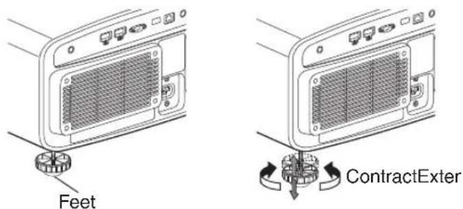
4 Locations

Connecting the Projector
- Do not turn on the power until connection is complete.
- The connection procedures differ according to the device used. For details, please refer to the instruction manual of the device to be connected.
- This projector is used for projecting images. To output the audio of connected devices, please connect a separate audio output device, such as an amplifier or speaker.
- Some cables cannot be connected to this unit due to the size of their connector cover.
Connecting to the DisplayPort Terminals
![This Unit To [DisplayPort 1] to [DisplayPort 2] Input Terminals DisplayPort Cable (Sold Separately) PC, etc. DisplayPort Terminal](/content/2026/07/1508159/images/a307d559f82b68d4fcee87d61700e9f4e9ba055c7ff43ecf287e3a1c5e0a9263.jpg)
- For single-channel input signals, connect to either [DisplayPort 1] or [DisplayPort 2] input terminals.
- For two-channel input signals, connect to the [DisplayPort 1] and [DisplayPort 2] input terminals.
→ "Types of Possible Input Signals" (P. 64)
• Video images may not appear if a cable that does not support HBR2 is used. Use a cable that supports HBR2. - When disconnecting the DisplayPort cable, make sure to release the latch and unplug the cable.
Connecting to the LAN Terminal
![graph TD A["This Unit"] -->|To["LAN"] Terminal| B["Connection Cable (Sold Separately)"] B --> C["Desktop PC, etc."] C --> D["Server"] D --> E["Hub"] E --> F["Network"] F --> C](/content/2026/07/1508159/images/b134afcd45ea0dc325451259bbd32906eb99e016ea7ebfea98329f04a76909b9.jpg)
- The network is used to control this unit. It is not used for sending or receiving video signals.
- Please contact your network administrator for information concerning the network connection.
- For more information on control, please refer to "External Control" P. 57.
Connecting to the RS-232C Terminal
![This Unit To [RS-232C] Terminal RS-232C Connection Cable (Sold Separately) Laptop, etc. RS-232C Terminal](/content/2026/07/1508159/images/b9cc0abd3175994ede02e5e247553c76917f86477c8a32059f4c9ee9507d22bf.jpg)
- For more information on control, please refer to "External Control" P. 57.
Connecting to the REMOTE Terminal
![This Unit To [REMOTE] Terminal Connection Cable (Sold Separately) Wired Remote Controller (Sold Separately)](/content/2026/07/1508159/images/767484e37b92e42adaee3f19621b2a0d99bff01ebe27e2e427fa1968dca4c3a7.jpg)
- For more details on the wired remote controller and connection cable, please consult your dealer.
Connecting the Power Cord (Supplied Accessory)

① Connect the power cord supplied to the power input terminal on the main unit
② Insert the supplied power plug into the wall outlet.

Precautions to prevent fire and electric shock
- The power consumption of this unit is large. Please connect it directly to the wall outlet.
- When you are not using the projector, please unplug the power cord from the outlet.
- Connect it using only the power cord supplied.
- Do not use a voltage other than the indicated power voltage.
- Do not damage, break or modify the power cord. Do not place a heavy object on the power cord, or heat or pull it. Doing so may damage the power cord.
- Do not unplug the power cord with wet hands.
Viewing Videos

![graph TD A["INPUT"] --> B["STANDS BY"] B --> C["SETTING MEMORY"] C --> D["LENS CONTROL"] D --> E["ON"] E --> F["Remote Control"] style A fill:#f9f,stroke:#333 style B fill:#ccf,stroke:#333 style C fill:#cfc,stroke:#333 style D fill:#fcc,stroke:#333 style E fill:#cff,stroke:#333 style F fill:#ffc,str…](/content/2026/07/1508159/images/ebe21f5e2cee2de1d61c62022dde7afb900ee9d91688d8fcc12bd4b2b321e8d8.jpg)

MEMO
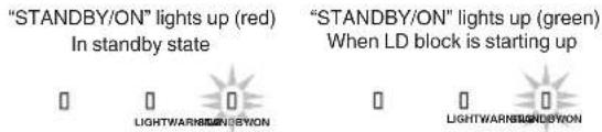
- Connect the power cord, and ensure that the "STANDBY/ON" indicator lights up in red.
1 Turn on the power
Remote control: press the I [ON] button
Projector unit: press the ⏻/I button
2 Choose the image to project
Press the [INPUT] button on this unit or remote control to switch the input.
- Pressing the button each time switches the setting in the following sequence: "DisplayPort 1" → "DisplayPort 2" → "Dual"...
- Play back the selected device to project the image.
* Refer to "Types of Possible Input Signals" P. 64.
To hide the image temporarily
Press the [HIDE] button on the remote control
- The "STANDBY/ON" indicator light starts to blink in green. When "LED Indication" is set to "Off", the indicator does not blink.
- Press the [HIDE] button again to resume display of the image.
- The power cannot be turned off when the image is temporarily hidden.
3 Turn off the power
Remote control: press the ⏻ [STANDBY] button
Projector unit: press the ⏻/I button
- While the “Are you sure you want to turn off?” message is displayed, press the button again.
- Thelight of the LD block goes off, and the “STANDBY/ON” indicator switches from a green light to a red blinking light.
- After the light goes off, the fan will run for about 10 seconds to cool down the LD block (Cool-down mode). Do not disconnect the power cable while cooling is in progress.
- After about 10 seconds, the "STANDBY/ON" indicator switches from a blinking red to a solid red light.
"STANDBY/ON" blinking (red) In the Cool-down mode

"STANDBY/ON" lights up (red) In standby state
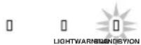

CAUTION
- The power cannot be turned off within approximately 30 seconds after it has been turned on.
- The power cannot be turned on again while cooling is in progress (10 seconds).
- Pull out the power plug when the unit is not to be used for a prolonged period of time.
- If the indication of indicator differs from the description, refer to "Indicator Display on the Main Unit" P. 67 for details.
Adjustments and Settings in the Menu
Pressing the [MENU] button displays the menu.
Press the [▲▼◀▶] keys to select an item, followed by pressing the [OK] button to confirm the selection.
List of Menu Items
Picture Adjust
▶ Picture Mode ...... P. 29
→ Sharpness ...... P. 29
→ FEDLC P. 29
→ Auto Intensity ...... P. 29
→ LD Current ...... P. 29
→ Aperture P. 29
→ User Name Edit ...... P. 30
▶ Color Management ...... P. 30
▶ Color Temp. P. 31
▶ Gamma ...... P. 32
▶ Blur Reduction ...... P. 33
→ Clear Motion Drive ...... P. 33
→ Motion Enhance ...... P. 33
▶ Contrast P. 33
▶ Brightness ...... P. 33
▶ Color P. 33
▶Tint P. 33
Input Signal
▶ Input Level ...... P. 34
▶ Color Space ...... P. 34
▶ Channel Hide ...... P. 34
Installation
▶ Lens Control ...... P. 35
→ Focus P. 35
→ Zoom P. 35
→ Shift P. 35
→ Image Pattern P. 35
→ Lock P. 36
▶ Pixel Adjust P. 37
→ Adjust P. 37
→ Adjust Area P. 37
→ Adjust Color P. 37
→ Adjust Pattern P. 37
→ Adjust Pattern Color P. 37
→ Adjust (Pixel) P. 37
→ Adjust (Fine) P. 37
→ Reset P. 37
▶ Mask P. 41
▶ Installation Style ...... P. 41
▶ LED Indication ...... P. 41
▶ High Altitude Mode ...... P. 41
▶ Auto Geometry Stabilizer P. 41
Display Setup
▶ Back Color ...... P. 44
▶ Menu Position ...... P. 44
▶ Signal Display P. 44
▶ Logo P. 44
Function
▶ Sync Out ...... P. 45
▶ Off Timer P. 45
▶ Network P. 45
▶ Remote Code ...... P. 46
▶ Hide Mode P. 46
▶ Software Update ...... P. 46
Information
You can adjust the image quality according to the type of video image you are viewing.
| Setting Description | |
| Natural Image quality that focuses | on natural color and gradation reproduction. Suitable for displaying video images in general. |
| Dynamic This is the picture setting | best suited for viewing the picture in a room that cannot be made completely dark. |
| User 1 to User 6 Enables user-defined image quality data to be saved and retrieved. | |
You can configure the following setting items by pressing the [MENU] button to display the menu, followed by selecting "Picture Adjust" → "Picture Mode" and pressing the [OK] button.
Sharpness
The sharpness of the image can be adjusted.
- Setting: 0 (low sharpness) to 50 (high sharpness)
FEDLC
Expands the dynamic range by controlling the LD current based on information superimposed on the image data.
| Setting Description | |
| Off Deactivates the function. LD current is the value configured in “LD Current” or the current value controlled by “Auto Intensity”. | |
| On Activates the function. | |
* This item cannot be set when "Auto Intensity" is set to "On".
Auto Intensity
Controls the LD current value to maintain the projector brightness at a constant level.
| Setting Description | |
| Off Light intensity is manually set. | |
| On Light intensity will be constant. |
* If the "Aperture" setting is changed, the light intensity does not remain constant even when "On" is set.
* This item cannot be set when "FEDLC" is set to "On".
LD Current
Controls the brightness of the light source by controlling the LD current.
- Setting range: 38 to 118.5
* This function is disabled when "Auto Intensity" is set to "On" or when "FEDLC" is set to "On".
Aperture
For changing the brightness through controlling the aperture.
- Setting range: -7 (stops down) to 0 (opens up)
User Name Edit
You can edit the "User 1" to "User 6" names in the Picture mode.
- Characters that are usable include alphabets (upper or lower case), numeric characters, and symbols.
- Enter not more than 10 characters.
![User Name Edit Name User 1 Input Cursor Selection Cursor A B C D E F G H I J K L M N O P Q R S T U V W X Y Z a b c d e f g h i j k l m n o p q r s t y v w x y z 1 2 3 4 5 6 7 8 9 0 , . ^ ! ' # $ % & ^ + - / = ? @ : : ! ~ ( ) < > [ ] { } \ Space OKAll ClearCl... After entry is complete, select "OK" a…](/content/2026/07/1508159/images/0ae308975b7ffb1cd68a819279f78a30a5efcff44de27de9313b84295f1c0fb1.jpg)
Color Management
Each of the colors is adjustable according to the user's preference.
1 Select the “Picture Adjust” → “Color Management” menu, and press the [OK] button.
2 Set "Color Management" to "On", and press the [OK] button
3 Adjust to the preferred color
① Select "Color Selection", and press the ◀▶ keys to select the color to adjust
- For color adjustment, select the color from the following: "Red", "Yellow", "Green", "Cyan", "Blue", "Magenta".
② Adjust the selected color
| Item | Setting Range | Description |
| Axis Position - | 30 to 30 Fine-tune the position of the central axis of the selected color. | |
| Hue -30 to 30 | Adjusts the hue (color tone). | |
| Saturation -30 | to 30 Adjusts the color saturation (vividness). -30 (dull) to +30 (vivid) | |
| Brightness -30 | to 30 Adjusts the brightness. -30 (dark) to +30 (bright) | |
- Selecting "Reset" resets all the adjustment data.
- Pressing the [HIDE] button on the remote control enables you to check the image before adjustment. Press the [HIDE] button again to return to the adjustment screen.

4 Press the [MENU] button to exit
Color Temp.
For setting the color temperature of the video image.
- The selectable "Color Temp." settings vary according to "Picture Mode".
"Color Temp."
| Color Temp. Description | |
| 6500K Increasing the value enhances the blue tone of the video image, while decreasing the value enhances the red tone. | |
| 7500K | |
| High Bright Color temperature that gives priority to brightness. | |
| Custom 1 to Custom 2 The color temperature of video images can be adjusted manually and saved as one of the three customized settings. | |
List of selectable "Color Temp." according to "Picture Mode"
| Picture Mode Color Temp. | |
| NaturalUser 1 to User 6 | 6500K |
| 7500K | |
| High Bright | |
| Custom 1 to Custom 2 | |
| Dynamic High Bright | |
Correction Value
For setting the base color temperature for the adjustment of "Gain Red" / "Gain Green" / "Gain Blue" / "Offset Red" / "Offset Green" / "Offset Blue" when one of the "Custom 1" to "Custom 2" setting is selected in "Color Temp.".
- If the color profile is imported using the calibration software, select "Default".
- The selectable correction values vary according to "Picture Mode". (Refer to the table below.)
List of selectable "Correction Value" according to "Picture Mode"
| Picture Mode Correction | Value |
| NaturalUser 1 to User 6 | 6500K |
| 7500K | |
| High Bright | |
| Default | |
| Dynamic Not selectable |
Gain Red / Gain Green / Gain Blue
Adjusts each color in the bright parts of the video image.
- Setting range: -255 (reduces the red/green/blue tone) to 0 (no adjustment)
Offset Red / Offset Green / Offset Blue
Adjusts each color in the dark areas of the video image.
- Setting range: -50 (reduces the red/green/blue tone) to 0 (no adjustment) to +50 (enhances the red/green/blue tone)
Gamma
You can adjust the output value of the projected image with respect to the video signal input.
"Gamma"
| Gamma Description | |
| 2.2 The gamma is set to “2.2”. | |
| Custom 1 to Custom 3 Enables fine adjustment of gamma according to preference. | |
You can perform fine adjustments based on the selected gamma adjustment setting.
Correction Value
For configuring the gamma to be used as the basis for adjustment when one of the “Custom 1” to “Custom 3” settings is selected in “Gamma”.
Adjustment item and its setting
| Item Description | Setting | |
| Color Selection For selecting the color for adjusting “Picture Tone”, “Dark Level” and “Bright Level”. | White / Red / Green / Blue | |
| Picture Tone Adjusts the overall brightness automatically for a well-balanced result without compromising the gradation of the image. | -16 (darkens image for an underexposed effect) to +16 (brightens image for an overexposed effect) | |
| Dark Level Adjusts the dark areas of the input image.• To do so, use the ◀▶ keys to move the cursor. | -7 (darkens the shadows) to +7 (brightens the shadows) | |
| Bright Level Adjusts the bright areas of the input image.• To do so, use the ◀▶ keys to move the cursor. | -7 (darkens the highlights) to +7 (brightens the highlights) | |
When "Correction Value" is set to "Import"
- By selecting "Import" for "Correction Value", the gamma data created externally can be selected as the base setting value for adjustment.
- The factory setting for "Import" is "2.2".
- You can use the calibration software to customize the gamma data adjustment, and import the created gamma data.
Please check with your authorized dealer for details.
Blur Reduction
For reducing the after-image, which occurs in a fast-moving scene.
- Blur Reduction is grayed out and cannot be adjusted when signal is out of range or when detecting the input.
Clear Motion Drive
For reducing the after-image, which occurs in a fast-moving scene.
- Pressing the [C.M.D.] button each time switches the mode in the following sequence: "Off" → "Mode 1" → "Mode 2" → "Mode 3" → "Off"...
* C.M.D. is the abbreviation for Clear Motion Drive.
| Setting Description | |
| Off Turns Off the blur reduction features. | |
| Mode1 Applies black insertion to reduce blurriness in the video images slightly. | |
| Mode2 Applies black insertion to reduce blurriness in the video images moderately.The video images are slightly darkened in this mode. | |
| Mode3 Applies black insertion to minimize blurriness in the video images.The screen may flicker in this mode. | |
Motion Enhance
You can reduce motion blur with this function enhancing the response of D-ILA image devices. If the image outline is unnatural, set this item to "Off".
| Setting Description | |
| Off Does not perform correction. | |
| On Reduces image blurring. | |
| Gain | When Motion Enhance is set to “On”, the overall intensity is adjusted using Gain, while adjustment of each color is performed using Red/Green/Blue. |
| Red | |
| Green | |
| Blue |
Contrast
For adjusting the white level point to avoid clipping or over saturation.
- Setting range: -50 (little difference in brightness) to +50 (large difference in brightness)
Brightness
For adjusting the black level point to avoid clipping or over saturation.
- Setting range: -50 (darker) to +50 (brighter)
Color
For adjusting the color density of the video image.
- Setting range: -50 (lighter) to +50 (deeper)
Tint
For adjusting the hue of the video image.
- Setting range: -50 (reddish) to +50 (greenish)
Input Level
For setting the dynamic range (gradation) of the video input.
- If the dynamic range is not appropriate, the bright areas become overexposed, and the dark areas become underexposed.
| Setting Description | |
| 16-235 (Video) Select this setting if you are inputting video signals (dynamic range: 16 - 235). | |
| 0-255 (PC) Select this setting if you are inputting PC signals (dynamic range: 0 - 255). | |
Color Space
For setting the color space of the input signal.
| Setting Description | |
| YCbCr444 Select this setting when | inputting YCbCr (4:4:4) video signals. |
| YCbCr422 Select this setting when | inputting YCbCr (4:2:2) video signals. |
| RGB Select this setting when inputting RGB video signals. | |
Channel Hide
A function for configuring whether to display video images for each DisplayPort input terminal.
| Setting Description | ||
| DP 1 | Off Displays video images with the Hide function disabled. | |
| DP 2 | On Enables the Hide function and does not display video images. | |
Lens Control
Focus / Zoom / Shift
For adjusting the lens according to the projection position

MEMO
To use the Shift function, a motorized lens shift unit is required. For details on installing the motorized lens shift unit (sold separately), refer to the instruction manual of the motorized lens shift unit. Motorized lens shift unit (product no.: PK-MLS01)
1
Press the [LENS CONTROL] button, and use the [▲▼◀▶] keys to adjust Focus, Zoom (screen size), and Shift (screen position)
![graph LR A["LENS CONTROL"] --> B["Focus"] B --> C["OK"]](/content/2026/07/1508159/images/f77820c92c13651c6477b345eb95d8a629a3159120588190c9409213b851cc3b.jpg)
- Pressing the [LENS CONTROL] or [OK] button each time switches the mode in the following sequence: "Focus" → "Zoom" → "Shift" → "Focus"...

Focus Adjustment

Zoom (Screen Size) Adjustment

Shift (Screen Position) Adjustment
- If the driving range of the motorized lens shift unit is exceeded, the projected screen cannot be shifted anymore when the lens reaches the end.
- Pressing and holding the [▲▼◀▶] keys continuously after the projected screen cannot be shifted anymore will overload the motor causing malfunction.
2 Press the [MENU] or [BACK] button to end adjustment
Image Pattern
For setting whether to display the lens adjustment pattern.
| Setting Description | |
| Off Displays external signals, and does not display the lens adjustment pattern. | |
| On Displays the lens adjustment pattern. | |
Adjustment Pattern Displayed on the Adjustment Screen
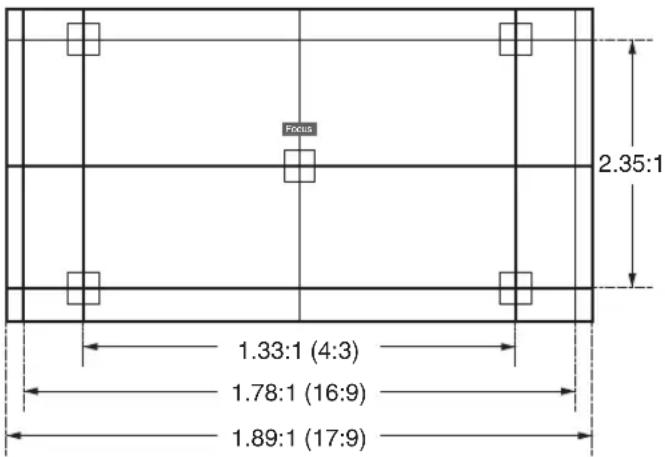
Adjust the display according to the viewing angle of the respective aspect ratios for the adjustment patterns.
* This is not displayed when "Image Pattern" is configured to "Off".
Lock
For setting whether to lock or unlock the lens.
Setting to "On" to lock the lens allows you to preserve the adjustment status of the lens.
| Setting Description | |
| Off Does not lock the lens. | |
| On Locks the lens to prevent any erroneous operation on the adjustments. | |
Pixel Adjust
For correcting the phase shifting between each RGB color by adjusting the pixel.
Adjust
For setting the adjustment feature to On or Off.
Adjust Area
| Setting Description | |
| Whole Adjusts the entire image. | |
| Zone Enables fine adjustment of each area by dividing the screen evenly into 10 vertical and horizontal zones. | |
Adjust Color
For selecting the color to adjust ("Red" or "Blue").
Adjust Pattern
| Setting Description | |
| Off Displays the external signals without displaying the test pattern for adjustment. | |
| On Displays the test pattern for adjustment. | |
Adjust Pattern Color
For setting the color of the adjustment pattern displayed during adjustment to "White" or "Yellow / Cyan".
Adjust (Pixel)
When “Adjust Area” is set to “Whole”, adjustment can be made by moving in units of one pixel on the screen of the cold selected in “Adjust Color”.
→ "Whole Adjust (Pixel) Operation Procedure" (P. 38)
- Adjustment cannot be made when "Adjust Area" is set to "Zone".
- Adjustment cannot be made when "Mode" of "Auto Geometry Stabilizer" is configured to "On".
| Setting Description | |
| H (Horizontal) Setting range: -2 (moves red/blue to the left) to +2 (moves red/blue to the right) | |
| V (Vertical) Setting range: -2 (moves red/blue downward) to +2 (moves red/blue upward) | |
Adjust (Fine)
When “Adjust Area” is set to “Whole”, adjustment can be made by moving in units of 1/8 pixel on the screen of the color selected in “Adjust Color”.
→ "Whole Adjust (Fine) Operation Procedure" (P. 39)
When “Adjust Area” is set to “Zone”, the screen is divided evenly into 10 vertical and horizontal zones, and fine adjustment of each area is possible.
→ "Zone Adjust Operation Procedure" (P. 40)
| Setting Description | |
| H (Horizontal) Setting range: -31 (moves red/blue to the left) to +31 (moves red/blue to the right) | |
| V (Vertical) Setting range: -31 (moves red/blue downward) to +31 (moves red/blue upward) | |
Reset
Restores all pixel adjustment data to the factory default.

Whole Adjust (Pixel) Operation Procedure
For making general adjustments to slight color fringing in the horizontal/vertical directions of the video image.
① Set “Adjust Area” to “Whole”
② Select "Adjust Color" and "Adjust Pattern Color"
③ Select "Adjust (Pixel)", and press the [OK] button
- The Adjustment mode is activated, and the selected adjustment pattern and Adjustment (Pixel) window are displayed.

④ Use the [▲▼◀▶] keys to move and adjust the vertical and horizontal pixels of the entire zone
- The adjustment setting appears at the center of the Adjustment (Pixel) window.

⑤ After adjustment is complete, press the [BACK] button to exit the Adjustment mode
Remote Control Operation Guide
| Button Name Function Description of Operation | ||
| [PICTURE MODE] Adj. | Col. Changes “Adjust Color”. | |
| [C.M.D.] Pixel/Fine Switches between “Adjust (Pixel)” and “Adjust (Fine)”.• Switches to “Adjust (Pixel)” when “Adjust Area” is set to “Zone”. | ||
| [GAMMA SETTINGS] Pat.Col. Changes “Adjust Pattern Color”. | ||
| [ADVANCED MENU] Adj.Area | Switches “Adjust Area”.• A zone cursor appears on the adjustment pattern when the “Zone” setting is selected. | |

Whole Adjust (Fine) Operation Procedure
For making general adjustments on the misalignment of the entire screen using “Adjust (Pixel)”, followed by making fine adjustments.
① Set “Adjust Area” to “Whole”
② Select "Adjust Color" and "Adjust Pattern Color"
③ Select Adjust (Fine), and press the [OK] button
- The Adjustment mode is activated, and the selected adjustment pattern and Fine window are displayed.
- The adjustable range may be smaller depending on the pixels being adjusted on the entire screen.
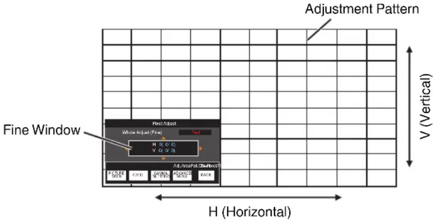
④ Use the [▲▼◀▶] keys to move and adjust the vertical and horizontal pixels of the entire zone
- The adjustment setting appears at the center of the Fine window.

⑤ After adjustment is complete, press the [BACK] button to exit the Adjustment mode

MEMO
- If both the maximum overall screen misalignment of H (horizontal direction) and V (vertical direction) are “31”, you cannot select a value that is larger than the displayed setting even when the adjustment setting is lower than the maximum value.
- If the minimum overall screen misalignment is “-31”, you cannot select a value that is smaller than the displayed setting even when the adjustment setting is higher than the minimum value.
Zone Adjust Operation Procedure
For fine-tuning misalignments on a part of the screen after adjusting the overall screen misalignment using “Adjust (Pixel)” and “Adjust (Fine)”.
- The screen can be divided vertically and horizontally into 10 sections for partial adjustments to be made.
① Set "Adjust Area" to "Zone"
② Select "Adjust Color" and "Adjust Pattern Color"
③ Select Adjust (Fine), and press the [OK] button
- The Adjustment mode is activated, and the selected adjustment pattern and Zone Adjustment window are displayed.
- The adjustable range may be smaller depending on the pixels being adjusted on the entire screen.

④ Press the [▲▼◀▶] keys to move the cursor to the point to be adjusted
⑤ Press the [OK] button to enter the Adjustment mode
⑥ Use the [▲▼◀▶] keys to move and adjust the vertical and horizontal pixels of the entire zone
- The adjustment setting appears at the center of the Zone Adjustment window.

⑦ After adjustment is complete, press the [BACK] button to exit the Adjustment mode
Mask
For hiding the peripheral area of the image with a mask (black strip).
| Setting Description | |
| Off Not masked. | |
| On Hides the ranges specified in “Top”, “Bottom”, “Left” and “Right” by masking (with black strips). | |
Off

On

Mask: black strip around the periphery
"Top" / "Bottom" / "Left" / "Right"
For specifying the ranges to hide by masking (with black strips).
- Setting range: 0 to 220
Installation Style
For setting to "Front", "Ceiling Mount (F)", "Rear", or "Ceiling Mount (R)" according to the installation status of the projector.
- "Front" or "Ceiling Mount (F)" is set when projector is installed in the front with respect to the screen.
- "Rear" or "Ceiling Mount (R)" is set when projector is installed in the rear with respect to the screen.
* When using the projector with the lens shifted in the vertical direction, the amount of distortion at the upper and lower ends may be different and the curvature distortion may not be fully corrected.
LED Indication
When "LED Indication" is set to "Off", the LED indicator does not light up or blink under the following status.
- When the time to replace the laser light source is near. (P. 47)
- When HIDE is on. (P. 67)
- When the projector receives a signal from a remote control which is set to a different code mode (A or B). (P. 46)
High Altitude Mode
For setting the high altitude mode to "On" or "Off".
Set to "On" when using the projector at a location of low atmospheric pressure (higher than 900 m above sea level).
Auto Geometry Stabilizer
For correcting the phase shifting between each RGB color due to the temperature according to the duration after starting up. Phase shift correction is performed every minute for 120 minutes from startup according to the preconfigured correction value.
- When this function is used, up to 4 pixels on either the left or right end will be missing depending on the amount of correction.
Mode
For configuring the correction feature to On or Off.
- The menu options under "Adjust" are not available when "Mode" is configured to "Off".
- "Adjust (Pixel)" of "Pixel Adjust" is not available when "Mode" is configured to "On".
Adjust Pattern
| Setting Description | |
| Off Displays the external signals without displaying the test pattern for adjustment. | |
| On Displays the test pattern for adjustment. | |
Adjust
For configuring the correction value according to the current time.
- Correction values can be configured for up to four points.
- After configuration of the correction values for the four points is complete, “Adjust” will not be selectable. To configure the setting, do so after erasing the unwanted correction values.
| Setting Description | |
| H (Horizontal) Setting range: -4 (moves Red/Green/Blue to the left) to +4 (moves Red/Green/Blue to the right) | |
| V (Vertical) Setting range: -4 (moves Red/Green/Blue downward) to +4 (moves Red/Green/Blue upward) | |
Point 1 to 4
For editing or erasing preconfigured correction values directly.
The configured time is displayed in "Point 1 to 4" after configuration of the correction values is complete.
Reset
For erasing the preconfigured correction values in Point 1 to 4.

Operation procedure on the Adjust Screen

① Select "Adjust", and press the [OK] button to display the adjustment screen.
② Configure the correction value by using the [▲▼◀▶] keys to move the vertical and horizontal pixels.
③ Press the [PICTURE MODE] button on the remote control to switch the color to adjust. (Red→Green→Blue)
④ Press the [C.M.D.] / [GAMMA SETTINGS] / [ADVANCED MENU] button on the remote control to switch between showing and hiding the image for each RGB color.
⑤ After adjustment is complete, press the [BACK] button to exit the adjustment screen.
Remote Control Operation Guide
| Button Name Function Description of Operation | ||
| [PICTURE MODE] Adj. | Col. For selecting the color for adjusting. | |
| [C.M.D.] R Mute Switches between showing and hiding the R signal. | ||
| [GAMMA SETTINGS] G | Mute Switches between showing and hiding the G signal. | |
| [ADVANCED MENU] B | Mute Switches between showing and hiding the B signal. | |

Display Setup
Back Color
For setting the color of the background to "Blue" or "Black" when there is no signal input.
Menu Position
For setting the display position of the menu.
Signal Display
For setting the display of the input information to "On" or "Off".
| Setting Description | |
| Off Not displayed. | |
| On Shows the input terminal for 5 seconds when input is switched. | |
Logo
For setting the display of logo during startup to "On" or "Off".
| Setting Description | |
| Off Not displayed. | |
| On Displays the “D-ILA” logo for 5 seconds during startup. | |
Sync Out
For selecting the type of signal to output from Sync Out.
| Setting Description | |
| Input (Positive) Outputs a signal that is synchronized with the vertical sync signal of the input video signal. | |
| Input (Negative) Outputs a signal with reversed polarity that is synchronized with the vertical sync signal of the input video signal. | |
| Low Fixes the output at Low. | |
| High Fixes the output at High. | |
| FEDSC Outputs a signal that is synchronized with the polarity information included in the FEDSC packet. Outputs a Low when there is no FEDSC packet. | |
Off Timer
For setting the duration before the power turns off automatically when the projector is not operated.
- Setting values: "Off", "1 Hour", "2 Hours", "3 Hours" and "4 Hours"
* The setting will be retained even after the Off Timer operation has completed.
Network
For specifying the settings for external control from a PC or smartphone.
| Setting Description | ||
| DHCP Client On Obtains | the IP address automatically from the DHCP server inside the connected network. | |
| Off For configuring the network settings manually. | ||
| IP Address For configuring the IP address. | ||
| Subnet Mask For configuring the subnet mask. | ||
| Default Gateway For configuring the default gateway. | ||
| MAC Address Displays the MAC address of the unit. | ||
| Set Applies the network settings. | ||

Glossary of Network Terminology
| DHCP | : Abbreviation for Dynamic Host Configuration Protocol. This is a protocol for the network to assign an IP address automatically to the connected device. |
| IP Address | : Numeric characters for identifying the device that is connected to the network. |
| Subnet Mask | : Numeric characters that define the bit count used for the network address that is a segment of the IP address. |
| Default Gateway | : Server for communicating beyond the network that is divided by the subnet mask. |
| MAC Address | : Abbreviation for Media Access Control address. This is a number that is unique to each network adapter. Each of the network adapters is assigned with a unique MAC address. |
Remote Code
For changing the remote control code.
| Setting Description | |
| A Change the remote control code | from “B” to “A”. |
| B Change the remote control code | from “A” to “B”. |
- You need to configure the remote control according to the settings of this unit.
On the remote control unit, press the [MENU] and [BACK] buttons at the same time for three seconds or longer to switch the code.
- The backlight of the remote control blinks 3 times: change the remote control code to "A"
- The backlight of the remote control blinks 2 times: change the remote control code to "B"
- If the setting differs between this unit and the remote control, the “STANDBY/ON” indicator blinks in green when receiving the remote control code.


(Green)
Hide Mode
For reducing the power consumption through suppressing the current supply for the LD block when the [HIDE] button is pressed to hide the image temporarily.
| Setting Description | |
| Off Do not suppress the current supply | apply when the [HIDE] button is pressed to hide the image temporarily. |
| On Suppresses the current supply | when the [HIDE] button is pressed to hide the image temporarily. |
Software Update
For performing a software update.
For the latest information on the software, refer to https://www3.jvckenwood.com/english/download/.

Information
Page 1
| Setting Description | |
| Input Displays video input terminal. | |
| Status Displays the image output status. | |
| Resolution(DP 1 / DP 2) Displays the resolution information of signal input to each of the DP 1 and DP 2 terminals. | |
| Light Source Time Displays the laser light source time. | |
| Soft Ver. Displays the firmware version. |
Pages 2 to 3
| Setting Description | |
| DP 1 to DP 2 Displays the terminal | for which the corresponding information is displayed. |
| Resolution | Displays the image resolution. |
| H Frequency | Displays the horizontal frequency. |
| V Frequency | Displays the vertical frequency. |
| Color Depth Displays the color bit | depth of the input video signal.• Displayed when Deep Color information is received from the source device. |
| Color Space Displays the Color Space | ace detected by AVI Info frame. |
| Link Rate Displays the transmission | frequency of the input signal. |
| Lane Count Displays the number of lanes | used for the input signal. |
Maintaining the Cabinet and Remote Control
• Gently wipe off dirt on the cabinet with a soft cloth.
- If it is extremely dirty, wet a cloth in water, wring dry and use it to wipe off the dirt, followed by wiping again with a dry cloth.
- Pay attention to the following as the cabinet may deteriorate in condition or the paint may come off.
- Do not wipe with thinner or benzine
- Do not allow prolonged contact with rubber or plastic products
- Do not spray volatile chemicals such as insecticide
Cleaning and Replacing the Filter
Clean the filter regularly. Using a filter without cleaning may reduce the brightness of the image. Dirt that enters the unit may also appear as shadows on the image.

1 Loosen the screws at the four corners and remove the cover
- The screws cannot be removed from the cover. Do not try to remove the screws from the cover by force.
2 Remove the sponge spacer
3 Use a vacuum cleaner to remove dirt from the sponge spacer carefully
4 Restore the sponge spacer to the original position
5 Restore the cover and fasten the screws at the four corners

CAUTION
- Do not wash the air filter with water. Doing so may cause the filter to deteriorate.
- Make sure to attach the air filter and sponge spacer in the correct sequence.

MEMO
- If the air filter or sponge spacer is damaged and requires replacement, or if dirt gets into the unit, consult your authorized dealer or nearby service center.
• Air filter Product no.: F1K-0173-00 - Sponge spacer Product no.: J3K-0134-00
Long term storage of projector
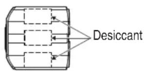
If projector is to be stored or not powered up from more than 3 month, it is recommended that the projector be stored in a sealed bag with desiccant.

CAUTION
1) If projector is run on a normal cycle weekly or powered on for at least 8 hours every 90 days, no action is required.
2) Desiccant should be changed every year or sooner if exposed to humid environment.
- Desiccant Product no :LC43436-001A
- Sealed bag Product no :LC43435-002A

About the Lens
- This projector does not come with a projection lens.
To use the projector, please mount a projection lens according to your requirements. - When using an optional standard zoom lens or short focus lens, a spacer and shift plate are required. Use the spacer that comes with this unit. The shift plate varies depending on the tilting angle of the lens so please contact our sales representative.
- To use the Shift function, a motorized lens shift unit is required. (Sold separately)
(Optional Extras>
Standard zoom lens (product no.: GL-MZ4014SZ)
Short focus lens (product no.: GL-MZ4009SZ)
Motorized lens shift unit (product no.: PK-MLS01)
Mounting the Lens
When installing the lens using the shift plate, do so according to the following procedures. When using the optional motorized lens shift unit (PK-MLS01), refer to its instruction manual.

CAUTION
- Before attaching the lens, check to make sure that the power of the projector is not turned on and the power cord is not connected. Failure to do so may cause electric shock or injuries.
- When using the projector in an environment where vibration occurs continuously, tighten the mounting screws periodically or apply treatment to the screws for mounting before use to prevent them from loosening.
* The recommended tightening torque for the screws for mounting the lens is 1.47N·m (15kgf·cm).
1 Unscrew the 4 screws using a Phillips screwdriver to remove the front cover

Front Cover
2 Unscrew the screw using a Phillips screwdriver to remove the front plate

Front Plate
3 Secure the lens spacer to the shift plate using the supplied screws

4 Attach the spacer and insert lens
- Attach the Lens Spacer and Shift Plate to the Lens Holder and fasten using the 4 screws packed with Lens Spacer using a Phillips screwdriver.
- Insert the lens with the connector rightward.

5 Connect the motor cable
- Connect the motor cable (20pin) to lens.

CAUTION
- Keep the cable away from the motor gear when clamping the motor cable.
6 Tighten the 4 screws using the Phillips head screwdriver to fasten the lens
- Use the screws that comes with the lens.
* The recommended tightening torque for the screws for mounting the lens is 1.47N·m (15kgf·cm).

7 Clamp the motor cable

8 Install the front base (Supplied Accessory)

9 Attach the front cover, and fasten using the 4 screws using a Phillips screwdriver

Troubleshooting
Before sending the unit to your authorized dealer for repair, please check the following points.
The following symptoms are not malfunctions.
You do not need to worry about the following symptoms if there is no abnormality on the screen.
- A part of the top or front surface of the unit is hot.
- A creaking sound is heard from the unit.
- An operating sound is heard from the inside of the unit.
• Color smear occurs on some screens.
This unit is a digital device. This unit may become unable to operate normally due to external static or noise. Perform the following operations when such malfunctions occur.
① If the unit is in the Standby mode, pull out the power plug, followed by inserting it again
② Press the ⏻/I button on the projector unit to turn on the power again
Power is not supplied
| Check Action Refer to | ||
| Is the power cord disconnected? Insert the power cord (plug) firmly. P. 24 | ||
| Is the unit in the Cool-down mode? After exiting the Cool-down mode, turn on the power again. P. 26 | ||
Power shuts down automatically
| Check Action Refer to | ||
| Has “Off Timer” been configured? Set “Off Timer” to “Off”. P. 45 | ||
| Are the air inlets and exhaust vent blocked? | Leave proper clearance when installing the unit. P. 15, 20 | |
| Is there a large amount of dirt attached to remove the dirt using a vacuum cleaner. P. 48 the sponge filter? | ||
Video image does not appear
| Check Action Refer to | ||
| Is the correct external input selected? Select the correct external input terminal. P. 25 | ||
| Is the power of the AV device or PC turned on? | Turn on the power of the AV device or PC and play the video. | P. 23 |
| Is the AV device or PC properly connected? | Connect the AV device or PC properly. P. 23 | |
| Are the correct signals being output from the AV device or PC? | Set the AV device or PC properly. P. 23 | |
Video image looks unnatural
Colors are unnatural
| Check Action Refer to | ||
| Is the color space of the input signal correctly set? | The color may turn out unnatural when the input signal is different from that in the projector setting. Set the “Color Space” for “Input Signal” correctly. | P. 34 |
| Is the image correctly adjusted? Adjust “Color” and “Tint” accordingly. P. 33 | ||
| Is the AV device or PC properly connected? | Connect the AV device or PC properly. P. 23 |
* The video image may appear slightly reddish immediately after starting up. This is not a malfunction.
Video image is fuzzy
| Check Action Refer to | ||
| Is the focus correctly adjusted? Adjust the focus. P. 35 | ||
| Is the unit placed too near or too far away from the screen? | Set the unit at a correct distance from the screen. P. 62 | |
Projected image is dark
| Check Action Refer to | ||
| Is the laser light source near exhaustion? | Check the laser light source time in the “Information” menIf 20,000 hours have elapsed, the brightness will be half the brightness at shipment. | P. 47 |
| Is the aperture closed? Increase the value of the “Aperture” setting. P. 29 | ||
| Is the value of the “LD Current” setting small? | Increase the value of the “LD Current” setting. P. 29 | |
Striped patterns appear on the screen
| Check Action Refer to | ||
| Does the fabric of the screen have a regular pattern? | Interference fringes may sometimes occur between the fabric pattern and the pixels. Please consult the authorized dealer. | — |
Video images are missing
| Check Action Refer to | ||
| Has screen mask been configured? Set | “Mask” to “Off”. | P. 41 |
Zoom or focus does not work
| Check Action Refer to | ||
| Is the lens replaced? Depending on the lens position, the lens may not work when it has been replaced.While at the Focus / Zoom adjustment screen, press and hold the ▲ or ▼ key for 2 seconds or longer. Doing so will allow the lens to recover from this condition. | P. 35 |
Remote control does not work
| Check Action Refer to | ||
| Are the batteries correctly loaded? | Match the polarities (⊕⊖) correctly when loading the batteries. | P. 18 |
| Are the batteries exhausted? Replace with new batteries. P. 18 | ||
| Is there an obstructing object between the remote control and remote sensor? | Remove any obstructing object. P. 18 | |
| Is the remote control held too far away from the unit? | Hold the remote control closer to the sensor during use. P. 18 | 18 |
Noise is heard
| Check Action Refer to | ||
| Is the exhaust vent blocked?Is the unit used near a heater or air-conditioner? | Check the installation condition of the projector.When the surrounding temperature of the projector is high, the fan revolution speed increases to protect the projector unit, hence a louder operating sound. | P. 20 |
There are small black or colored dots on the screen
The D-ILA device is manufactured using high-precision technologies, but there may be some (less than 0.01%) missing pixels or pixels that remain permanently lit. This is not a malfunction.
When the Following Messages Appear...
| Message Description | Action | |
 | No device is connected to the input terminal.The input terminal is connected but there is no signal. | Input the video signals. |
 | A video signal that cannot be used with this unit has been input (the names of input terminals such as “DP 1” will be displayed in yellow). | Input video signals that can be used.(P. 64) |
External Control
It is possible to control this unit by connecting it to a PC using an RS-232C cross cable (D-sub 9-pin).
The projector can be controlled by connecting it to a PC through the computer network with a LAN cable for control commands to be sent to the projector.
→ “Network” (P. 45)
- Please use it after you have gained proper understanding from professional books or consulting the system administrator.
RS-232C Specifications

| Pin No. Signal Function Signal Direction | |||
| 2 RxD Receive data PC → | This unit | ||
| 3 TxD Transmission data This unit → PC | |||
| 5 GND Signal ground | — | ||
| 1, 4, 6 - 9 N/C | — | — | |
- PC refers to the controller, such as a personal computer.

| Mode Non-synchronous | |
| Character length 8 bit | |
| Parity None | |
| Start bit 1 | |
| Stop bit 1 | |
| Data rate 19200 bps | |
| Data format | Binary |
TCP/IP Connection
Before controlling via LAN, it is necessary to establish connection of the TCP layer by a "3-way handshake", followed by sending out "PJREQ" and receiving "PJACK" within five seconds after the projector sends out "PJ_OK" for connection authentication.
If you are unable to complete sending within five seconds, or when "PJ_NG" or "PJNAK" is received, check the operating status of the projector, followed by performing the steps again starting from establishment of a TCP connection.
![graph TD A["Projector"] --> B["Establishment of TCP Connection TCP Port No. 20554 3-way Handshake"] B --> C["Controlling PC"] C --> D["PJ_OK"] D --> E["PJREQ"] E --> F["PJACK"] F --> G["Connection Authentication Procedure"] G --> H["Within 5 Seconds"] H --> I["Projector Control"]](/content/2026/07/1508159/images/ad2ecb1bc875fc2f07d83d554714ddf462925e2db04a0b70130061df4235a3ec.jpg)
Command Format
The command between this unit and the computer consists of "Header", "Unit ID", "Command", "Data" and "End".
- Header (1 byte), Unit ID (2 bytes), Command (2 bytes), Data (n bytes), End (1 byte)
Header
This binary code indicates the start of communication.
| Binary Code Type | Description | |
| 21 Operating command | PC → | This unit |
| 3F Reference command | PC → | This unit |
| 40 Response command | This unit → PC | |
| 06 ACK This unit → PC | (returns to PC after the | command is accepted without error) |
Unit ID
This is a code that specifies the unit. The binary code is fixed at "8901".
Command and data
Operating command and data (binary code)
| Command | Type Description | |
| 0000 | Connection check | Check whether communication is enabled between this unit and the PC during standby. |
| 5057 Power supply | During standby31: Turns on the powerWhen power is on30: Turns off the power (Standby mode) | |
| 4950 Input | When power is on38: DP 139: DP 2 | |
| 5243 Remote control | Sends the same code as the supplied remote control.“Remote Control Code”P. 59 | |
Reference command and data (binary code)
| Command | Type Description | |
| 5057 Power supply | During standby or when power is on30: Standby mode31: When power is on32: In the Cool-down mode34: When error occurs on this unit | |
| 4950 Input | When power is on38: DP 139: DP 2 | |
End
This code indicates the end of communication. The binary code is fixed at "0A".
Remote Control Code
Binary code is sent during communication.
- The following applies to the case when the remote control code is “A”. In the case of “B”, add “36” to the beginning of the code.
| Remote Control Button Name | Binary Code |
| STANDBY 37 33 30 36 | |
| ON 37 33 30 35 | |
| INPUT 37 33 30 38 | |
| LENS CONTROL 37 33 33 | 30 |
| HIDE 37 33 31 44 | |
| INFO. 37 33 37 34 | |
| ▲ | 37 33 30 31 |
| ▼ | 37 33 30 32 |
| ◀ | 37 33 33 36 |
| ▶ | 37 33 33 34 |
| OK 37 33 32 46 | |
| MENU 37 33 32 45 | |
| BACK 37 33 30 33 | |
| PICTURE MODE 37 33 46 | 34 |
| GAMMA SETTINGS 37 33 | 46 35 |
| C.M.D. 37 33 38 41 | |
| ADVANCED MENU 37 33 | 37 33 |
Communications Example
This section shows the communication examples of RS-232C.
Operating command
| Type Command Description | ||
| Connection check PC → This unit: 21 89 01 00 00 0AThis unit → PC: 06 89 01 00 00 0A | Connection check | |
| Power (On) PC → This unit: 21 89 01 50 57 31 0AThis unit → PC: 06 89 01 50 57 0A | When power is turned on from the Standby mode | |
| Power (Off) PC → This unit: 21 89 01 50 57 30 0AThis unit → PC: 06 89 01 50 57 0A | When power is turned off (Standby mode) from power-on mode | |
| Remote control (MENU) | PC → This unit: 21 89 01 52 43 37 33 32 45 0AThis unit → PC: 06 89 01 52 43 0A | When the same operation as pressing the [MENU] button on the remote control is performed |
Reference command
| Type Command Description | ||
| Power (On) PC → | This unit: 3F 89 01 50 57 0AThis unit → PC: 06 89 01 50 57 0AThis unit → PC: 40 89 01 50 57 31 0A | When information on the power-on state is acquired |
| Input (DP 1) PC → This | unit: 3F 89 01 49 50 0AThis unit → PC: 06 89 01 49 50 0AThis unit → PC: 40 89 01 49 50 38 0A | When information on DP 1 input is acquired |
Specifications
| Product Name D-ILA Projector | ||
| Model Name DLA-VS3000G | ||
| Display Panel/Size D-ILA device *1, 2 | 0.69" 4K D-ILA (4096 x 2160 pixels) x 3 | |
| Light Source Blu-Escent Laser / Phosphor | ||
| Screen Size Approx. 60" to 300" (Aspect ratio of 4096 x 2160) | ||
| Brightness 1600 lm | ||
| Projection Distance Refer to P. 62. | ||
| Input Compatibility Signal Refer to P. 64. | ||
| Display Resolution 4096 x 2160 pixels | ||
| Input Terminal DisplayPort Input DisplayPort 1.2a, 20-pin (male) x 2 | ||
| Output Terminal SYNC OUT Mini jack, TTL output x 1 *3 | ||
| Control Terminal | RS-232C Terminal Single, D-sub 9-pin (male) x 1 *4 | |
| Remote Terminal Stereo mini jack (remote control) x 1 | ||
| LAN Terminal | Single, RJ45 jack, 10BASE-T/100BASE-TX x 1 | |
| Service Terminal | SERVICE | Single (USB Type A) x 1 *5 |
| Power Requirements | AC 100 V to 240 V, 50 Hz/60 Hz | |
| Power Consumption | 440 W (during standby: 1.5 W *6) | |
| Operation Environment | Temperature: 5°C to 35°C; humidity: 20% to 80%; storage temperature: -10°C to 60°C | |
| Installation Height | Below 6,561 ft (2,000 m) | |
| Dimensions (Width x Height x Depth) | 500 mm x 234 mm x 518 mm (including feet) | |
| Mass | 22.5 kg | |
| Accessories | Refer to P. 13. | |
*1 D-ILA is the abbreviation for Direct Drive Image Light Amplifier.
*2 D-ILA devices are manufactured using extremely high-precision technology with a pixel effectiveness of 99.99%. Only 0.01% or less of the pixels are either missing or would remain permanently lit.
*3 For synchronizing with other equipment.
*4 For external control.
*5 Exclusively for firmware update.
*6 The power consumption of this product during networked standby when all wired network ports are connected is 1.5 W.
- Design and specifications are subject to change without prior notice.
- Please note that some of the pictures and illustrations may have been abridged, enlarged or contextualized in order to aid comprehension. Images may differ from the actual product.
Screen Size and Projection Distance
GL-MZ4009Z
| Screen Size Diagonal (Inch) | Projection Distance (m) | |||
| 17:9 Screen 16:9 Screen | ||||
| Wide-end Tele-end Wide-end Tele-end | ||||
| 60 1.22 1.74 1.29 1.83 | ||||
| 70 1.44 2.04 1.52 2.15 | ||||
| 80 1.65 2.34 1.74 2.47 | ||||
| 90 1.87 2.65 1.97 2.78 | ||||
| 100 2.08 2.95 2.19 3.10 | ||||
| 110 2.30 3.25 2.42 3.42 | ||||
| 120 2.52 3.55 2.65 3.74 | ||||
| 130 2.73 3.85 2.87 4.05 | ||||
| 140 2.95 4.15 3.10 4.37 | ||||
| 150 3.16 4.46 3.33 4.69 | ||||
| 160 3.38 4.76 3.55 5.00 | ||||
| 170 3.59 5.06 3.78 5.32 | ||||
| 180 3.81 5.36 4.01 5.64 | ||||
| 190 4.02 5.66 4.23 5.95 | ||||
| 200 4.24 5.96 4.46 6.27 | ||||
| 210 4.45 6.26 4.69 6.59 | ||||
| 220 4.67 6.57 4.91 6.90 | ||||
| 230 4.88 6.87 5.14 7.22 | ||||
| 240 5.10 7.17 5.36 7.54 | ||||
| 250 5.32 7.47 5.59 7.85 | ||||
| 260 5.53 7.77 5.82 8.17 | ||||
| 270 5.75 8.07 6.04 8.49 | ||||
| 280 5.96 8.37 6.27 8.81 | ||||
| 290 6.18 8.68 -- | ||||
| 300 6.39 8.98 -- | ||||
GL-MZ4014Z
| Screen Size Diagonal (Inch) | Projection Distance (m) | |||
| 17:9 Screen 16:9 Screen | ||||
| Wide-end Tele-end Wide-end Tele-end | ||||
| 60 1.66 3.43 1.75 3.61 | ||||
| 70 1.96 4.02 2.06 4.23 | ||||
| 80 2.25 4.60 2.37 4.84 | ||||
| 90 2.54 5.19 2.67 5.46 | ||||
| 100 2.83 5.77 2.98 6.07 | ||||
| 110 3.12 6.36 3.28 6.69 | ||||
| 120 3.41 6.94 3.59 7.30 | ||||
| 130 3.70 7.53 3.90 7.92 | ||||
| 140 3.99 8.11 4.20 8.53 | ||||
| 150 4.28 8.70 4.51 9.15 | ||||
| 160 4.58 9.28 4.81 9.76 | ||||
| 170 4.87 9.87 5.12 10.38 | ||||
| 180 5.16 10.45 5.43 10.99 | ||||
| 190 5.45 11.04 5.73 11.61 | ||||
| 200 5.74 11.62 6.04 12.22 | ||||
| 210 6.03 12.21 6.34 12.84 | ||||
| 220 6.32 12.79 6.65 13.45 | ||||
| 230 6.61 13.38 6.95 14.07 | ||||
| 240 6.90 13.96 7.26 14.68 | ||||
| 250 7.19 14.55 7.57 15.30 | ||||
| 260 7.49 15.13 7.87 15.91 | ||||
| 270 7.78 15.72 8.18 16.53 | ||||
| 280 8.07 16.31 8.48 17.14 | ||||
| 290 8.36 16.89 - - | ||||
| 300 8.65 17.48 - - | ||||
Types of Possible Input Signals
Single - DP1 - DP2
| Original Input Signal | ||||||||||
| Designation | Resolution | Projector Terminal for Connection | Resolution fn [kHz] fv [Hz] | dot CLK [MHz] | Total No. of Dots [dot] | Total No. of Lines [line] | No. of Effective Dots [dot] | No. of Effective Lines [line] | ||
| VGA 640 x 480 | x 1080 1920 | [DP 1]/ [DP 2] x 1080 56.25 | 640 x 480 31 | .469 59.94 | 0 25.18 800 | 525 640 480 | ||||
| 1080p 1920 | 0 50.000 148 | .50 2640 1 | 125 1920 1 | 080 | ||||||
| 67.433 59 | 940 148.35 | 2200 1125 | 1920 1080 | |||||||
| 67.500 60 | 000 148.50 | 2200 1125 | 1920 1080 | |||||||
| 2K 2048 x 1080 | x 1200 1600 | x 1200 75.00 x 1200 74. | 0.000 148.50 | 2640 1125 | 2048 1080 | |||||
| 67.433 59 | 940 148.35 | 2200 1125 | 2048 1080 | |||||||
| 67.500 60 | 000 148.50 | 2200 1125 | 2048 1080 | |||||||
| UXGA 1600 | 0 60.000 162 | .00 2160 1 | 250 1600 1 | 200 | ||||||
| WUXGA 1920 | x 1200 1920 | x 1200 74. | 556 59.885 1 | 93.25 2592 | 1245 1920 | 1200 | ||||
| QXGA | 2048 x 1536 | 2048 x 1536 | 95.446 59.95 | 54 267.25 2 | 800 1592 2 | 048 1536 | ||||
| WQXGA 2560 | x 1600 2560 | x 1600 99. | 458 59.987 3 | 48.50 3504 | 1658 2560 | 1600 | ||||
| 4K 3840 x 2160 | x 3840 x 2160 | x 3840 x 2160 | 3.976 296.70 | 5500 2250 | 3840 2160 | |||||
| 54.000 24 | 000 297.00 | 5500 2250 | 3840 2160 | |||||||
| 56.250 25 | 000 297.00 | 5280 2250 | 3840 2160 | |||||||
| 67.433 29 | 970 296.70 | 4400 2250 | 3840 2160 | |||||||
| 67.500 30 | 000 297.00 | 4400 2250 | 3840 2160 | |||||||
| 112.500 50 | 0.000 594.00 | 0 5280 2250 | 3840 2160 | |||||||
| 134.865 59 | 9.940 593.41 | 4400 2250 | 3840 2160 | |||||||
| 135.000 60 | 0.000 594.00 | 4400 2250 | 3840 2160 | |||||||
| 4096 x 2160 | 4096 x 2160 | 53.946 23.97 | 76 296.70 | 500 2250 | 4096 2160 | |||||
| 54.000 24 | 000 297.00 | 5500 2250 | 4096 2160 | |||||||
| 56.250 25 | 000 297.00 | 5280 2250 | 4096 2160 | |||||||
| 67.433 29 | 970 296.70 | 4400 2250 | 4096 2160 | |||||||
| 67.500 30 | 000 297.00 | 4400 2250 | 4096 2160 | |||||||
| 112.500 50 | 0.000 594.00 | 0 5280 2250 | 4096 2160 | |||||||
| 134.865 59 | 9.940 593.41 | 4400 2250 | 4096 2160 | |||||||
| 135.000 60 | 0.000 594.00 | 0 4400 2250 | 4096 2160 | |||||||
* For WQXGA, the display is dot-by-dot.
Dual - stripes
| Original Input Signal | ||||||||||
| Designation | Resolution | Projector Terminal for Connection | Resolution fh [kHz] fv [Hz] | dot CLK [MHz] | Total No. of Dots [dot] | Total No. of Lines [line] | No. of Effective Dots [dot] | No. of Effective Lines [line] | ||
| WQXGA 2560 x 1600 [DP 1], [DP 2] | 160 135.0002048 x 2160 | 1280 x 1600 | 99.458 59.198 973 348 | 1752 1658 | 1280 1600 | |||||
| 198.916 11 | 50 1752 16 | 58 1280 16 | 00 | |||||||
| 4K 3840 x 2160 1920 x 2 | 60.000 297.00 | 0 2200 225 | 0 1920 216 | 0 | ||||||
| 270.000 12 | 00 2200 22 | 50 1920 21 | 60 | |||||||
| 112.500 50.00 | 000 297.00 | 2640 2250 | 2048 2160 | |||||||
| 135.000 60 | 0 2200 225 | 0 2048 216 | 0 | |||||||
| 270.000 12 | 00 2200 22 | 50 2048 21 | 60 | |||||||
![H H/2 H/2 Same for all frames V [DP 1] [DP 2]](/content/2026/07/1508159/images/46c97b4f1035a5426d4aec0109b78a9322384dbe69c8173c51b8409421518713.jpg)
Dual - frame sequential
| Original Input Signal | ||||||||||
| Designation | Resolution | Projector Terminal for Connection | Resolution fn [kHz] fv [Hz] | dot CLK [MHz] | Total No. of Dots [dot] | Total No. of Lines [line] | No. of Effective Dots [dot] | No. of Effective Lines [line] | ||
| WQXGA 2560 x 1600 | [DP 1], [DP 2] | 2560 x 1600 | 99.46 59.9 | 9 348.5 350 | 4 1658 2560 | 1600 | ||||
| 4K 3840 x 2160 x 3840 x 2160 | 4096 x 2160 | 94 593.4 440 | 00 2250 38 | 40 2160 | ||||||
| 135.00 60. | 00 594.0 44 | 400 2250 38 | 40 2160 | |||||||
| 112.50 50.00 | 594.0 528 | 0 2250 409 | 6 2160 | |||||||
| 134.87 59. | 94 593.4 44 | 400 2250 40 | 96 2160 | |||||||
| 135.00 60. | 00 594.0 44 | 400 2250 40 | 96 2160 | |||||||
![Odd number frame display V H [DP 1]](/content/2026/07/1508159/images/f874dc4af103ae27ebfe9c0163425d2e35b71c4f35cdd2575931e3535e005a9c.jpg)
![Time direction ⇒ 60 Hz [DP 1] F1 F3 F5 ... [DP 2] F2 F4 F6 ... Output F1 F2 F3 F4 F5 F6 ... 120 Hz](/content/2026/07/1508159/images/7131b0975421902856791c4bb09fa0d504f50fc0ce97982e1e4c0cafeef52563.jpg)
![Even number frame display V [H] [DP 2]](/content/2026/07/1508159/images/b92f3d8c15293bae9cd20b3974104bd86b2a6f36c678363e852fd350c38fcafa.jpg)
Indicator Display on the Main Unit
Meaning of the front panel indicators

The indicator is solid.

The indicator appears blinking.

Operation mode display
Displays using the different colors and solid/blinking light of the indicator on the projector unit.
"STANDBY/ON" lights up (red)
• In standby state
"STANDBY/ON" lights up (green)
- When LD block is starting up


"STANDBY/ON" blinking (red)
• In the Cool-down mode
"STANDBY/ON" blinking (green)
- When the video image is temporarily hidden (HIDE is on) *


* "LIGHT" indicator does not blinking when "LED Indication" is set to "Off".
Estimated timing for laser light source replacement
Displays using the solid/blinking light of the "LIGHT" indicator.
* "LIGHT" indicator does not light up when "LED Indication" is set to "Off".
"LIGHT" lights up (orange)
- Lights up when the "LD Current" gauge reaches 95 and above. (When the "Auto Intensity" function is "On".)


Warning display
You can tell the details of a warning from the (repeated) displays of the "WARNING" and "LIGHT" indicators. The "STANDBY/ON" indicator will light up or appear blinking according to the operation mode of the projector unit. (Please refer to "Operation mode display" P. 67".)
The Warning mode is activated once the message is displayed. Projection is interrupted, and the cooling fan is turned on for about 10 seconds.
The power cannot be turned on again while cooling is in progress. Check the following after cooling is complete.
| Indicator Status | Blinking Frequency | Description Check and | Countermeasure | ||
 (Red) (*) Mode Display (Red) (*) Mode Display | x2 Cooling | fan stopped abnormally | • Check that nothing is blocking the air inlets.• Check that the external temperature is normal.Countermeasure: Leave the unit unoperated until it cools down. After that, turn on the power again. | ||
| x3 Internal | temperature is abnormally high | ||||
| x4 External | temperature is too high | ||||
 (Red) (Orange) Blinking Simultaneously (Red) (Orange) Blinking Simultaneously | x1 Abnormal | circuit operation | |||
| x2 | |||||
| x3 | |||||
| x4 | |||||
 (Red) (Orange) Display (Red) (Orange) Display | x1 | ||||
| x3 | |||||
| x4 When the safety switch is activated Request | for repair at your authorized dealer or a nearby service center. | ||||
 (Green) (Green) | x3 The remote control code differs between this unit and the remote control | Set the remote control code for this unit and the remote control correctly.(P. 46) | |||
If the Warning mode is activated again, wait for the cooling fan to stop, followed by pulling out the power plug from the outlet.
Request for repair at your authorized dealer or a nearby service center.
Dimensions
(Unit: mm)
Top Surface

Bottom Surface

Front
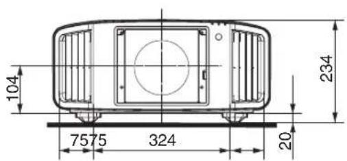
Rear Surface

Index
A Accessories....13
Adjust (Auto Geometry Stabilizer)....42
Adjust (Fine).... 37
Adjust (Pixel Adjust)....37
Adjust (Pixel)....37
Adjust Area (Pixel Adjust).... 37
Adjust Color (Pixel Adjust).... 37
Adjust Pattern (Auto Geometry Stabilizer)......42
Adjust Pattern (Pixel Adjust).... 37
Adjust Pattern Color (Pixel Adjust)...... 37
Adjusting the Position.... 22
Adjustments and Settings in the Menu....27
Aperture....29
Auto Geometry Stabilizer 41
Auto Intensity.... 29
Axis Position (Color Management)....30
B Back Color.... 44
Blur Reduction.... 33
Bright Level (Gamma)....32
Brightness....33
Brightness (Color Management).... 30
C Channel Hide.... 34
Cleaning and Replacing the Filter.... 48
Clear Motion Drive 33
Color.... 33
Color Depth (Information)...... 47
Color Management.... 30
Color Selection (Color Management)....30
Color Selection (Gamma).... 32
Color Space (Information)....47
Color Space (Input Signal).... 34
Color Temp.... 31
Connecting the Projector.... 23
Contrast.... 33
Controls and Features.... 14
Correction Value (Color Temp.) 31
Correction Value (Gamma).... 32
D Dark Level (Gamma)....32
Default Gateway.... 45
DHCP Client 45
Dimensions....69
Display Setup....44
E External Control.... 57
F FEDLC....29
Focus....35
Front base....13
Function......45
G Gain Blue.... 31
Gain Green.... 31
Gain Red....31
Gamma.... 32
H H Frequency (Information)...... 47
Hide Mode.... 46
High Altitude Mode.... 41
Hue (Color Management).... 30
I Image Pattern.... 35
Indicator Display.... 67
Information....47
Input (Information)......47
Input Level.... 34
Input Signal....34
Input Terminal.... 16
Installation....35
Installation Method....20
Installation Style....41
Installing the Projector....20
IP Address.... 45
L LAN Terminal.... 16, 23, 57
Lane Count (Information)...... 47
LD Current.... 29
LED Indication....41
Lens.... 14,50
Lens Control.... 35
Lens spacer.... 13
Light Source Time (Information)......47
Link Rate (Information)......47
List of Menu Items....27
Lock.... 36
Logo....44
Long term storage of projector.... 49
M MAC Address.... 45
Maintaining the Cabinet and Remote Control..... 48
Maintenance.... 48
Mask.... 41
Menu....19
Menu Position.... 44
Mode (Auto Geometry Stabilizer)......41
Motion Enhance....33
Mounting the Lens.... 50
N Network 45
O Off Timer....45
Offset Blue....31
Offset Green.... 31
Offset Red....31
P Picture Adjust....29
Picture Mode....29
Picture Tone (Gamma)....32
Pixel Adjust.... 37
Point 1 to 4....42
Power Cord.... 13, 24
Precautions during Installation.... 20
Projection Distance....62
R Remote Code....46
Remote Control....17
Resolution (Information)......47
RS-232C Terminal.... 16, 24, 57
S Safety Precautions....2
Saturation (Color Management)....30
Screen Size and Projection Distance....62
Screw....13
Securing (Mounting) the Projector.... 21
Securing the Projector (Ceiling Mount).... 22
Securing the projector (directly mount).... 21
SERVICE Terminal.... 16
Sharpness....29
Shift....35
Signal Display 44
Soft Ver. (Information)......47
Software Update.... 46
Specifications.... 61
Sponge....13
Status (Information)...... 47
Subnet Mask....45
Sync Out.... 45
T Tint....33
Troubleshooting....54
Types of Possible Input Signals.... 64
U User Name Edit....30
V V Frequency (Information)...... 47
Viewing Videos....25
W When the Following Messages Appear....56
Whole Adjust (Fine).... 39
Whole Adjust (Pixel)....38
Z Zone Adjust....40
Zoom....35
JVC
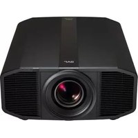
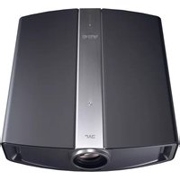
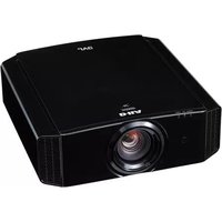
- FOR CUSTOMER USE
- SAFETY PRECAUTIONS
- IMPORTANT INFORMATION
- WARNING
- CAUTION
- NOISE EMISSION DECLARATION
- FCC INFORMATION (U.S.A. ONLY)
- NOTE
- ABOUT THE INSTALLATION PLACE
- SUPPLIER'S DECLARATION OF CONFORMITY
- IMPORTANT SAFEGUARDS
- DO NOT ALLOW ANY UNQUALIFIED PERSON TO INSTALL THE UNIT
- POWER CONNECTION
- DO NOT CUT OFF THE MAIN PLUG FROM THIS EQUIPMENT
- DEAR CUSTOMER
- IMPORTANT (EUROPE ONLY)
- ENGLISH
- INFORMATION FOR USERS ON DISPOSAL OF OLD EQUIPMENT AND BATTERIES
- [EUROPEAN UNION ONLY]
- FRANÇAIS
- FOR THE CUSTOMERS IN THE U.S.A. AND CANADA
- LOCATION INFORMATION OF THE LABELS
- BEAM DIVERGENCE ANGLE FROM LENS OF THIS UNIT
- CLASS 1 LASER PRODUCT
- SET UP
- OPERATE
- ADJUST/SET
- MAINTENANCE
- TROUBLESHOOTING
- OTHERS
- ACCESSORIES/OPTIONAL ACCESSORIES
- CHECK THE ACCESSORIES
- CONTROLS AND FEATURES
- MAIN UNIT - FRONT
- MAIN UNIT - BOTTOM
- MAIN UNIT - REAR
- ⑥ INPUT TERMINALS
- ⑦ OPERATION PANEL
- ⑧ REMOTE SENSOR (REAR)
- ⑨ POWER INPUT TERMINAL
- ⑩ AIR INLETS
- OPERATION PANEL
- MAIN UNIT - INPUT TERMINALS
- REMOTE CONTROL
- LOADING BATTERIES INTO THE REMOTE CONTROL
- EFFECTIVE RANGE OF REMOTE CONTROL UNIT
- CONTROL THROUGH REFLECTION OFF A SCREEN, ETC
- MENU
- INSTALLING THE PROJECTOR
- PRECAUTIONS DURING INSTALLATION
- WHEN CARRYING THIS UNIT
- DO NOT INSTALL AT THE FOLLOWING
- USING THE PROJECTOR
- MAINTAIN CLEARANCE FROM THE WALL, ETC
- INSTALLING THE SCREEN
- USING THE PROJECTOR AT A HIGH ALTITUDE
- PRECAUTIONS DURING MOUNTING
- SECURING THE PROJECTOR (DIRECTLY MOUNT)
- SCREW SPECIFICATIONS
- SECURING THE PROJECTOR (CEILING MOUNT)
- ADJUSTING THE POSITION
- ADJUSTING THE ELEVATION ANGLE OF THE PROJECTOR
- CONNECTING THE PROJECTOR
- CONNECTING TO THE RS-232C TERMINAL
- CONNECTING TO THE REMOTE TERMINAL
- CONNECTING THE POWER CORD (SUPPLIED ACCESSORY)
- PRECAUTIONS TO PREVENT FIRE AND ELECTRIC SHOCK
- VIEWING VIDEOS
- MEMO
- TURN ON THE POWER
- CHOOSE THE IMAGE TO PROJECT
- TURN OFF THE POWER
- ADJUSTMENTS AND SETTINGS IN THE MENU
- LIST OF MENU ITEMS
- PICTURE ADJUST
- INPUT SIGNAL
- INSTALLATION
- DISPLAY SETUP
- FUNCTION
- INFORMATION
- SHARPNESS
- FEDLC
- AUTO INTENSITY
- LD CURRENT
- APERTURE
- USER NAME EDIT
- COLOR MANAGEMENT
- COLOR TEMP
- CORRECTION VALUE
- GAIN RED / GAIN GREEN / GAIN BLUE
- OFFSET RED / OFFSET GREEN / OFFSET BLUE
- GAMMA
- WHEN "CORRECTION VALUE" IS SET TO "IMPORT
- BLUR REDUCTION
- CLEAR MOTION DRIVE
- MOTION ENHANCE
- CONTRAST
- BRIGHTNESS
- COLOR
- TINT
- INPUT LEVEL
- COLOR SPACE
- CHANNEL HIDE
- LENS CONTROL
- FOCUS / ZOOM / SHIFT
- PRESS THE [MENU] OR [BACK] BUTTON TO END ADJUSTMENT
- IMAGE PATTERN
- ADJUSTMENT PATTERN DISPLAYED ON THE ADJUSTMENT SCREEN
- LOCK
- PIXEL ADJUST
- ADJUST
- ADJUST COLOR
- ADJUST PATTERN COLOR
- ADJUST (PIXEL)
- ADJUST (FINE)
- RESET
- WHOLE ADJUST (PIXEL) OPERATION PROCEDURE
- WHOLE ADJUST (FINE) OPERATION PROCEDURE
- ZONE ADJUST OPERATION PROCEDURE
- MASK
- TOP" / "BOTTOM" / "LEFT" / "RIGHT
- INSTALLATION STYLE
- LED INDICATION
- HIGH ALTITUDE MODE
- AUTO GEOMETRY STABILIZER
- MODE
- ADJUST PATTERN
- POINT 1 TO
- OPERATION PROCEDURE ON THE ADJUST SCREEN
- BACK COLOR
- MENU POSITION
- SIGNAL DISPLAY
- LOGO
- SYNC OUT
- OFF TIMER
- NETWORK
- GLOSSARY OF NETWORK TERMINOLOGY
- REMOTE CODE
- HIDE MODE
- SOFTWARE UPDATE
- MAINTAINING THE CABINET AND REMOTE CONTROL
- CLEANING AND REPLACING THE FILTER
- LONG TERM STORAGE OF PROJECTOR
- ABOUT THE LENS
- MOUNTING THE LENS
- UNSCREW THE 4 SCREWS USING A PHILLIPS SCREWDRIVER TO REMOVE THE FRONT COVER
- UNSCREW THE SCREW USING A PHILLIPS SCREWDRIVER TO REMOVE THE FRONT PLATE
- SECURE THE LENS SPACER TO THE SHIFT PLATE USING THE SUPPLIED SCREWS
- ATTACH THE SPACER AND INSERT LENS
- CONNECT THE MOTOR CABLE
- TIGHTEN THE 4 SCREWS USING THE PHILLIPS HEAD SCREWDRIVER TO FASTEN THE LENS
- CLAMP THE MOTOR CABLE
- VIDEO IMAGE LOOKS UNNATURAL
- THERE ARE SMALL BLACK OR COLORED DOTS ON THE SCREEN
- WHEN THE FOLLOWING MESSAGES APPEAR
- EXTERNAL CONTROL
- RS-232C SPECIFICATIONS
- TCP/IP CONNECTION
- COMMAND FORMAT
- HEADER
- UNIT ID
- COMMAND AND DATA
- END
- REMOTE CONTROL CODE
- COMMUNICATIONS EXAMPLE
- SCREEN SIZE AND PROJECTION DISTANCE
- TYPES OF POSSIBLE INPUT SIGNALS
- INDICATOR DISPLAY ON THE MAIN UNIT
- MEANING OF THE FRONT PANEL INDICATORS
- OPERATION MODE DISPLAY
- ESTIMATED TIMING FOR LASER LIGHT SOURCE REPLACEMENT
- WARNING DISPLAY
- DIMENSIONS
- INDEX
- JVC
Brand : JVC
Model : DLA-VS3000
Category : Projector