
CD-RW 402 - CD Recorder TASCAM - Free user manual and instructions
Find the device manual for free CD-RW 402 TASCAM in PDF.

| Product Type | Professional CD Recorder |
| Model | CD-RW 402 |
| Brand | TASCAM |
| Disc Compatibility | CD-R, CD-RW |
| Main Functions | Recording, playback, editing, synchronization |
| Supported Audio Formats | CD-DA, MP3, WAV |
| Dimensions (W x H x D) | 482 x 88 x 260 mm |
| Weight | 4.5 kg |
| Power Supply | 220-240 V AC, 50/60 Hz |
| Power Consumption | 15 W |
| Audio Inputs | 2 x RCA, 2 x XLR, 1 x optical (TOSLINK) |
| Audio Outputs | 2 x RCA, 2 x XLR, 1 x optical (TOSLINK) |
| Digital Connectors | S/PDIF coaxial, AES/EBU (optional) |
| Control | LCD screen, transport buttons, jog wheel |
| Remote Control | Infrared included |
| Rack Mounting | 19 inches, 1U |
| Maintenance and Cleaning | Soft dry cloth, avoid abrasive products |
| Safety | Do not open, risk of electric shock; avoid moisture |
| Spare Parts and Repairability | Contact an authorized TASCAM dealer |
| General Information | Designed for professional use in studio and broadcasting |
Frequently Asked Questions - CD-RW 402 TASCAM
User questions about CD-RW 402 TASCAM
0 question about this device. Answer the ones you know or ask your own.
Ask a new question about this device
Download the instructions for your CD Recorder in PDF format for free! Find your manual CD-RW 402 - TASCAM and take your electronic device back in hand. On this page are published all the documents necessary for the use of your device. CD-RW 402 by TASCAM.
USER MANUAL CD-RW 402 TASCAM
CFX MKII SERIES OWNER'S MANUAL
12, 16, AND 20-CHANNEL MIC/LINE MIXERS WITH DIGITAL EFFECTS
IMPORTANT SAFETY INSTRUCTIONS
- Read these instructions.
- Keep these instructions.
- Heed all warnings.
- Follow all instructions.
- Do not use this apparatus near water.
- Clean only with dry cloth.
- Do not block any ventilation openings. Install in accordance with the manufacturer's instructions.
- Do not install near any heat sources such as radiators, heat registers, stoves, or other apparatus (including amplifiers) that produce heat.
- Do not defeat the safety purpose of the polarized or grounding-type plug. A polarized plug has two blades with one wider than the other. A grounding-type plug has two blades and a third grounding prong. The wide blade or the third prong are provided for your safety. If the provided plug does not fit into your outlet, consult an electrician for replacement of the obsolete outlet.
- Protect the power cord from being walked on or pinched particularly at plugs, convenience receptacles, and the point where they exit from the apparatus.
- Only use attachments/accessories specified by the manufacturer.
- Use only with a cart, stand, tripod, bracket, or table specified by the manufacturer, or sold with the apparatus. When a cart is used, use caution when moving the cart/apparatus combination to avoid injury from tip-over.
PORTABLE CART WARNING

Carts and stands - The Component should be used only with a cart or stand that is recommended by the manufacturer.
A Component and cart combination should be moved with care. Quick stops, excessive force, and uneven surfaces may cause the Component and cart combination to overturn.
- Unplug this apparatus during lightning storms or when unused for long periods of time.
- Refer all servicing to qualified service personnel. Servicing is required when the apparatus has been damaged in any way, such as power-supply cord or plug is damaged, liquid has been spilled or objects have fallen into the apparatus, the apparatus has been exposed to rain or moisture, does not operate normally, or has been dropped.
- This apparatus shall not be exposed to dripping or splashing, and no object filled with liquids, such as vases, shall be placed on the apparatus.
- This apparatus has been designed with Class-I construction and must be connected to a mains socket outlet with a protective earthing connection (the third grounding prong).
- This apparatus has been equipped with an all-pole, rocker-style AC mains power switch. This switch is located on the rear panel and should remain readily accessible to the user.
- This apparatus does not exceed the Class A/Class B (whichever is applicable) limits for radio noise emissions from digital apparatus as set out in the radio interference regulations of the Canadian Department of Communications.
- Exposure to extremely high noise levels may cause permanent hearing loss. Individuals vary considerably in susceptibility to noise-induced hearing loss, but nearly everyone will lose some hearing if exposed to sufficiently intense noise for a period of time. The U.S. Government's Occupational Safety and Health Administration (OSHA) has specified the permissible noise level exposures shown in the following chart.
According to OSHA, any exposure in excess of these permissible limits could result in some hearing loss. To ensure against potentially dangerous exposure to high sound pressure levels, it is recommended that all persons exposed to equipment capable of producing high sound pressure levels use hearing protectors while the equipment is in operation. Ear plugs or protectors in the ear canals or over the ears must be worn when operating the equipment in order to prevent permanent hearing loss if exposure is in excess of the limits set forth here.

| Duration Per Day In Hours | Sound Level dBA, Slow Response | Typical Example |
| 8 | 90 | Duo in small club |
| 6 | 92 | |
| 4 | 95 | Subway Train |
| 3 | 97 | |
| 2 | 100 | Very loud classical music |
| 1.5 | 102 | |
| 1 | 105 | Tami screaming at Adrian about deadlines |
| 0.5 | 110 | |
| 0.25 or less | 115 | Loudest parts at a rock concert |
WARNING — To reduce the risk of fire or electric shock, do not expose this appliance to rain or moisture.
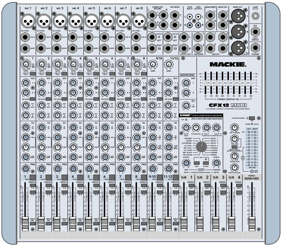
Thank you for choosing a Mackie CFX MKII mixer! These compact live-sound mixers are designed to meet the sound reinforcement needs of almost any small to medium-sized club, meeting room, sanctuary, or outdoor gathering.
Here's a quick glance at all the features you've acquired:
8, 12, or 16 mono channels, with:
Variable input gain
(+5 to +50 dB mic, -15 to +30 dB line)
- Phantom power (globally switched)
Zero Level gain setting indicator LED - Switchable 100 Hz low-cut filter
- TRS insert jack
2 pre/post-fader aux sends - 2 post-fader effects sends
3-band mid-sweep EQ
Pan, mute, and 1-2/3-4 busing
PFL solo - 60mm mono fader
2 stereo line channels, with:
Variable input gain (-20to + 20dB)
2 pre/post-fader aux sends
- 2 post-fader effects sends
4-band EQ
Pan, mute, and 1-2/3-4 busing
PFL solo
- 60mm stereo fader
Comprehensive master section, with:
- Four 60mm submix mono faders
- Separate Left and Right assign for each sub
- 60mm main mix stereo fader
TRS insert jacks for main mix
Balanced XLR stereo main outputs
Balanced XLR mono subwoofer output
12-segment stereo LED metering - Mackie's (in)famous Rude Solo Light
- 9-band stereo graphic EQ (main mix)
- EMAC™ 32-bit digital stereo effects with footswitch jack
2 aux sends with master level controls - 2 effects sends with master level controls
- Level controls for stereo effect returns
- Break switch for 'worry-free' intermissions
RCA tape out
RCA tape in with stereo level control - Headphone output with level control
- Utility out with level control
12VBNClamp socket
ABOUT THIS MANUAL
Absolutely most important page:
Before you start engineering, please read the "Quick Start" section on page 5. It's a list of steps that will familiarize you with the CFX mixer and help you set up a basic performance.
About those blue numbers:
You'll notice numbers in blue circles, like this: ⑦ . Every feature on the CFX mixer has one of these numbers assigned to it. Whenever a feature is mentioned, described or illustrated, its number will be right next to it.
Please write your serial number here for future reference (i.e., insurance claims, tech support, return authorization, etc.):
Purchased at:
Date of purchase:

CONTENTS
IMPORTANT SAFETY INSTRUCTIONS 2
INTRODUCTION 3
ABOUT THIS MANUAL 3
QUICK START 5
APPLICATIONS DIAGRAMS 6
PATCHBAY FEATURES 8
MIC 8
LINE IN 8
3 INSERT 8 EFFECTS: SERIAL OR PARALLEL? 9
STEREO LINE IN 9
5 MAIN OUT 9
6 SUBWOOFER OUT 9
MAIN INSERT 9
8 UTILITY OUT 10
SUB OUT 10
10 AUXSEND 10
11 EFX SEND 10
STEREO EFX RETURN 10
13 TAPE INPUT 11
14 TAPE OUTPUT 11
15 PHONES 11
16 EFX FOOTSWITCH 11
LAMP 11
18 AC POWER INPUT 11
19 POWER SWITCH 11
20 POWER STATUS 11
CHANNEL STRIP FEATURES 12
21 PHANTOM POWER 12
22 GAIN 12
23 ZERO LEVEL 12
24 LOW CUT 12
25AUX 12
26 PRE FADER 13
27 EFX 1 (EXT) 13
28 EFX 2 (INT) 13
29 EQ 13
30 PAN 14
31 MUTE 14
32 ASSIGN 14
33 FADER 14
34 SOLO PFL 14
MASTER SECTION FEATURES 15
35 MAIN MIX FADER 15
36 METERS 15
37 RUDE SOLO 15
38 STEREO GRAPHIC EQ 15
39 TAPE LEVEL 16
40 BREAK SWITCH 16
41 PHONES LEVEL 16
42 UTILITY OUT LEVEL 16
43 SUB FADERS 16
44 LEFT/RIGHT SUB ASSIGN 16
45 AUX MASTER SEND 17
46 EFX 1 MASTER SEND 17
47 EFX 1 RETURN 17
48 EMAC EFFECTS PROCESSOR 17
48 EFX 2 SEND 17
50 TO MAIN MIX 17
51 EFFECTS TO MONITOR 18
52 PRESET SELECT 18
53 TIME/RATE 19
54 DAMPING/DEPTH 19
55 WIDE 19
56 BYPASS 19
57 CLIP 19
GENERAL PRECAUTIONS AND CONSIDERATIONS .... 20
APPENDIX A: Service Info 20
Warranty Service 20
Troubleshooting 20
Repair 21
APPENDIX B: Technical Info 21
Specifications 21
Block Diagram 22
Contributors and Colophon 23
CFX MKII SERIES LIMITED WARRANTY 23

Don't forget to visit our website at www.mackie.com for more information about this and other Mackie products.
QUICK START

We know you can't wait to get the show on the road. Who has time to read a boooring manual? That's fine — the CFX MKII
mixer is designed to set up quickly and operate intuitively—but please, READ THIS PAGE!
ZERO THE CONSOLE:
- Turn everything off, including the mixer's POWER switch and PHANTOM POWER switch.
- Channel strip GAIN, AUX, EFX, and Fader down.
- STEREO GRAPHIC EQ sliders centered.
- MASTER AUX and EFX SENDS, and EFX RETURNS down.
- Channel strip EQ and PAN controls centered.
- Channel strip ASSIGN 1-2 and MUTE switches down.
- Channel strip LOW CUT, PRE FADER, and ASSIGN 3-4 switches up.
- SUB 1 ASSIGN LEFT, SUB 2 ASSIGN RIGHT down; all other SUB ASSIGN switches up.
- MAIN MIX and SUB Faders down.
MAKE THE CONNECTIONS:
- Connect your amp's outputs to your speaker inputs (unless, of course, you have powered monitors).
- Plug all the sound system components into suitable AC outlets, properly grounded and capable of delivering adequate current.
- Using XLR or TRS cables, make connections from your mixer's MAIN OUT to your amplification system's line inputs.
- Make connections from your microphones and instruments to the mixer: Connect balanced microphones to the mono channel MIC jacks. (For condenser microphones, engage the PHANTOM POWER switch, located just above the meters.) Connect line-level instruments (synthesizers, guitar effects, direct boxes) to the mono or stereo channel LINE IN TRS jacks.
- Turn all the power switches on, leaving the amplifier's switch for last.
- Turn up the MAIN MIX Fader to the "30" label, for now. We'll crank it up later on.
- Turn up SUB Faders 1 and 2 to unity gain ("U" label).

SET THE LEVELS:
- Choose one of the microphones or instruments you connected. Make some noise. If it's a microphone, sing at your normal singing volume. If it's a synthesizer, play it at its normal output level.
- While making noise, turn up that channel's GAIN until the adjacent ZERO LEVEL starts blinking.
- Disengage (up) that channel's MUTE.
- Raise that channel's fader to unity gain ("U" label). You should be hearing your noise now.
- If necessary, apply channel EQ changes. (You may need to compensate for level changes with the channel fader.)
- Repeat steps 1 through 5 for the remaining active channels.
- Stop making noise. Everyone: start making music.
TWEAK THE MIX:
- Engage MUTE on all channels except your rhythm section (drums & bass).
- Adjust the rhythm section's channel faders to get a good balance of levels.
- Un-mute the other active channels and adjust their faders.
- Now that you have a rough mix going, turn up the MAIN MIX Fader to a comfortable listening level.
- If the overall mix has an equalization problem, make adjustments to the STEREO GRAPHIC EQ. If an individual channel is the problem, use its EQ instead.
- Using channel EFX 2 (INT) and the EMAC EFFECTS PROCESSOR, experiment with adding some effects.
- Depending on how much time you've got, keep tweaking. Walk the room to see how it sounds away from your mixer. Keep tweaking.
KNOW THESE THINGS:
- Never listen to loud music for prolonged periods. Please see "Safety Instructions" on page 2 for information on hearing protection.
- Never plug amplifier outputs into anything except speakers.
- Never use guitar cables to connect amplifiers to speakers.
- Before making connections to an external amp or reconfiguring an amp's routing, turn the amp's level (gain) controls down, turn the power off, make the changes, turn the power back on, and then turn the level controls back up.
- When you shut down your equipment, turn off any external amplifiers first. When powering up, turn on the amplifiers last.
- Save the shipping box and packing material! You may need them someday, and you probably don't want to have to pay for that again.
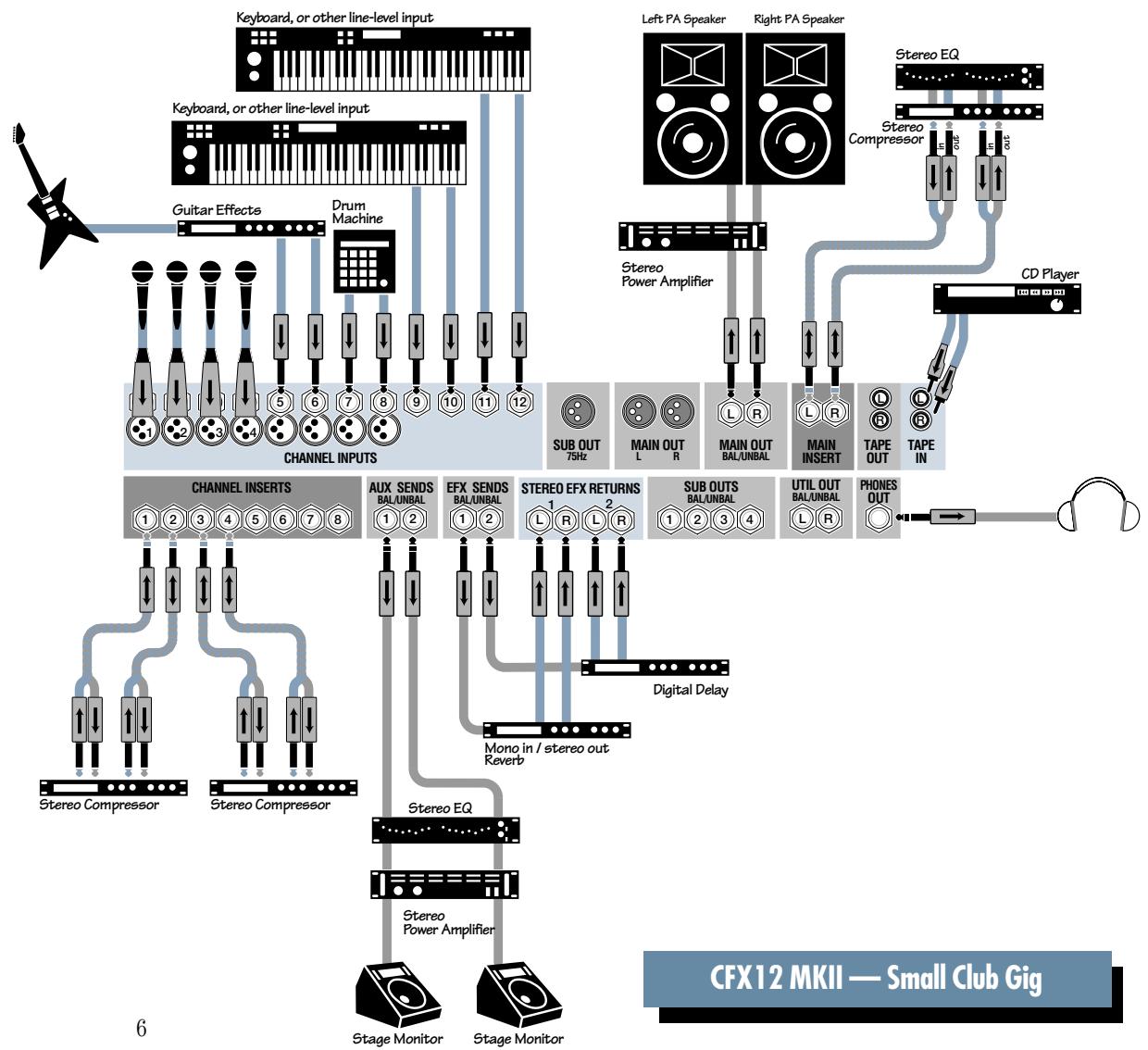
APPLICATIONS DIAGRAMS
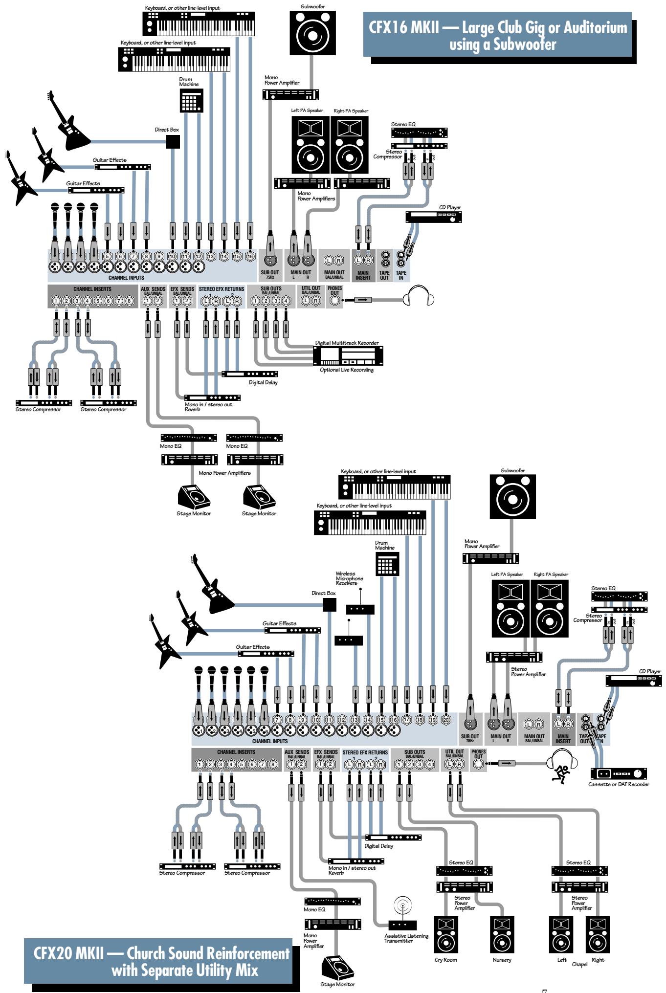
PATCHBAY FEATURES
At the risk of stating the obvious, this is where you plug everything in: microphones, line-level instruments, effects, headphones and the ultimate destination for your sound: PA system, tape recorder, etc.
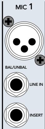
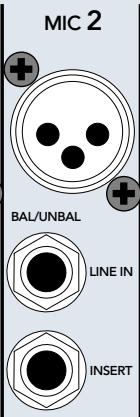
MIC
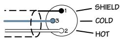
XLR BALANCED WIRING
The CFX MKII mixer is equipped with rugged, low noise, phantom-powered microphone preamplifiers, providing up to 50 dB of crystal-clear amplification. Their balanced circuitry rejects all manner of extraneous interference. Professional condenser, dynamic, and ribbon mics will all sound excellent through these XLR inputs.
You can plug in almost any kind of balanced mic that has a standard XLR-type male mic connector.
LINE
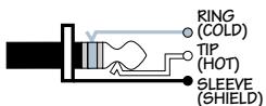
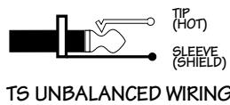
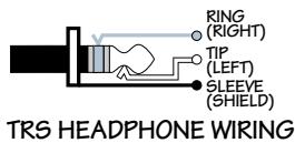
TRS BALANCED WIRING

TS UNBALANCED WIRING
The line inputs share circuitry (but not phantom power) with the mic preamps, and can be driven by balanced or unbalanced sources at almost any level. You can use these TRS inputs for virtually any signal you'll come across, from -25dBu up to +38dBu .
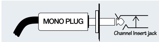
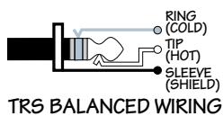
3 INSI
This is where you connect serial effects such as compressors, equalizers, de-essers or filters. The send is low-impedance (150 ohms), capable of driving any line-level device. The return is high-impedance (10k ohms) and can be driven by almost any device.
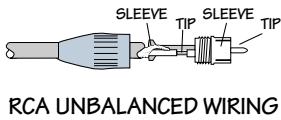
These unbalanced jacks are configured thusly:
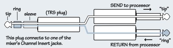
Tip = Send (to effects device input)
Ring = Return (from effects device output)
Sleeve = Common ground (connect shield to all three sleeves)
Specialty "Y" cables, developed just for these jacks, are widely available.
Besides being used for inserting external devices, these jacks can also be used as channel direct outputs; post-GAIN, post-LOW CUT, and pre-EQ. Here are three ways you can use the channel INSERTJacks:
Direct out with no signal interruption.
Insert only to first "click."

Direct out with signal interruption.
Insert all the way in to the second "click."

For use as an effects loop.
(TIP = SEND to effect, RING = RETURN from effect.)

EFFECTS: SERIAL OR PARALLEL?

Effects devices are used either in serial or in parallel: "Serial" means that the entire signal is routed through the effects device.
Examples: preamps, compressor/limiters, graphic equalizers.
"Parallel" means that a portion of the signal is tapped off to the device (usually via a mixer's aux send), processed and returned (usually via a mixer's aux return), to be mixed with the original "dry" signals. Multiple signals (via multiple mixer channels) can all make use of the same parallel effects device. Examples: reverb, digital delay, chorus. See diagrams below.
Serial Device
Parallel Device
STEREO LINE IN
These balanced inputs are designed for stereo or mono, balanced or unbalanced signals, from -20dB to +20dB . These TRS inputs can be used with just about any professional or semipro instrument, effect or tape player.
When connecting a mono device (just one cord), always use the LEFT (MONO) input and plug nothing into the RIGHT input. A trick called "jack normaling" will cause the signal to appear on both sides.
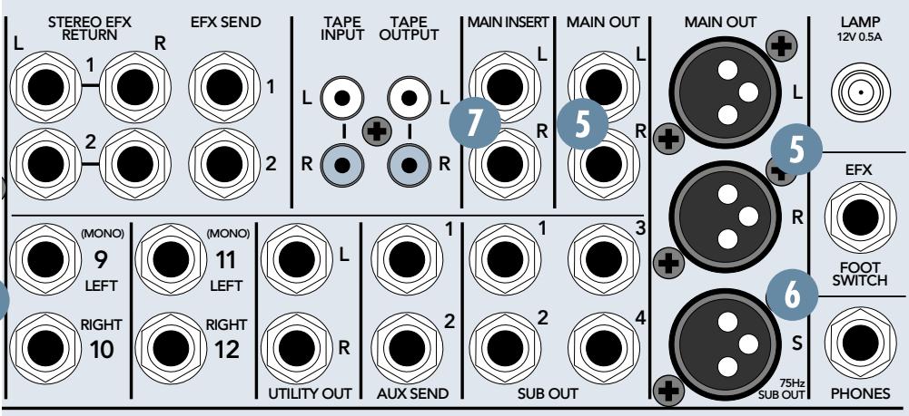
5 MAIN OUT
Coming in two flavors, XLR and TRS, the main output represents the end of the mixer chain, where your fully mixed and enhanced stereo signal enters the real world.
The XLR balanced outputs will add 6 dB when connected to balanced inputs, thereby elevating signal from the noise floor by that amount.
The TRS balanced outputs offer the advantage of having no 6 dB level change to deal with, while still providing extraneous noise rejection.
SUBWOOFER OUT
The CFX MKII mixer has an integrated mono-summing 75 Hz 3rd-order low-pass filter. It taps the left and right MAIN OUT ⑤ signals, mixes them into a mono signal, then removes all but the deepest bass information. Patch this balanced XLR output to a high-powered mono-summed amp and subwoofer (or an active subwoofer), and the music police will be right over.
MAIN INSERT
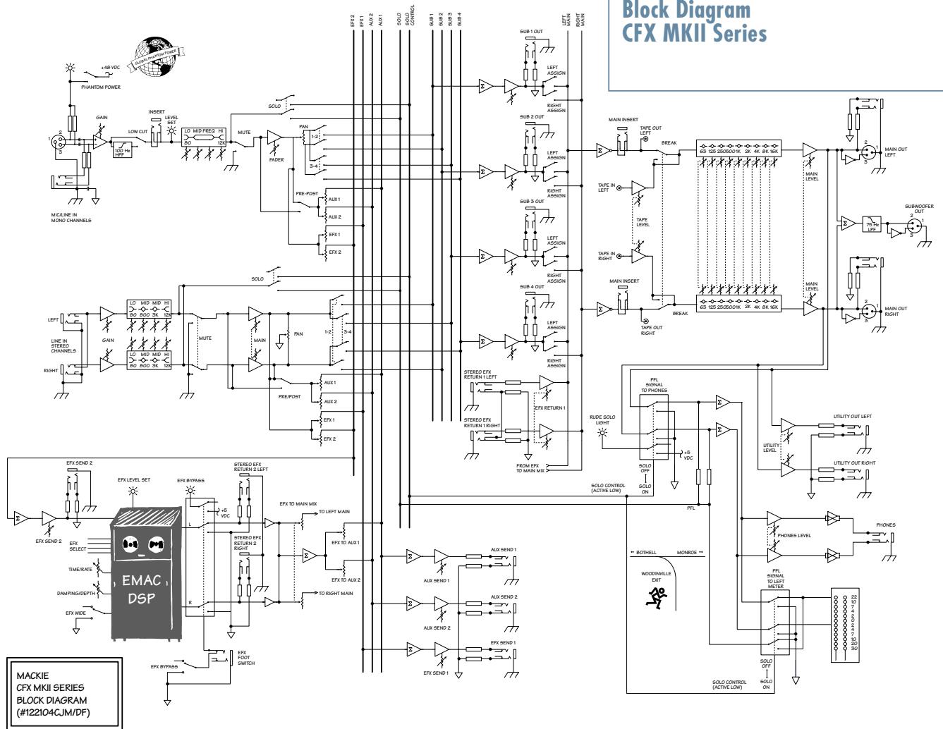
With nothing plugged into these jacks, the mix signal goes from the mix amp straight through to the MAIN MIX Faders 35. But when you plug a serial device into these jacks, the mix leaves the mixer, goes through the device and back into the mixer's main mix faders.
If you want to send your main mix through a compressor/limiter or similar device, these are the jacks for you. Since the insert is before the mix faders, moving the fader will not alter the signal strength sent to the compressor, thereby preserving its compression characteristics.
These unbalanced jacks are configured the same as the channel strip insert jacks. See page 8 for wiring and usage information.
UTILITY OUT
The stereo signal at these TRS jacks is the same as at the MAIN OUT 5, but with one important difference:
After the MAIN MIX Fader 35, the mix is sent through the UTILITY OUT LEVEL 42 control, allowing you to set levels as desired without disturbing the main mix level.
SUB OUT
In live sound applications, these TRS jacks can be patched into one or two stereo amplifiers, thereby allowing you to control levels independently via the SUB Faders 43.
Alternatively, use the MAIN OUT 5 to feed the amplifiers and one stereo SUB OUT 9 pair to feed a recorder.
In studio applications, these outputs can be used as four separate paths to feed four tracks of a multitrack recorder.
See ASSIGN 32 and SUB ASSIGN 44 for more information.
10 AUX SEND
To create a stage monitor mix, with levels set independently from the main mix, patch these TRS jacks into your monitor amplifier inputs. These jacks can also be used to feed the inputs of an effects device.
See AUX 25 and PRE FADER 26 for more information.
EFX SEND
The signal at these TRS outputs is postfader only, so they cannot be used as traditional stage monitor cues. They're intended to patch into effects device inputs; hence the name "EFX." See EFX 1 (EXT) and EFX 2 (INT) for more information.
Note: The EFX 2 signal path also feeds the CFX mixer's internal EMAC EFFECTS PROCESSOR inputs. If you're using EMAC and just one outboard processor, patch that processor via EFX SEND 1 for independent control of the effects send level.
We recommend going into a stereo reverb in mono and returning in stereo. We have found that on most "stereo" reverbs the second input just ties up an extra EFX send and adds nothing to the sound. There are exceptions, so feel free to try it both ways. If your effects device is true stereo all the way through, use EFX SEND 1 to feed its left input and EFX SEND 2 to feed the right input.
STEREO EFX RETURN
Patch the outputs of external parallel effects devices to these inputs.
Note: The EFX 2 return signal is combined with the signal from the CFX mixer's internal EMAC EFFECTS PROCESSOR ④ . If you're using EMAC and just one outboard processor, patch the outboard processor via EFX 1 RETURN for independent control of the effects return level.
When connecting a mono device (just one cord), always use the LEFT (MONO) input and plug nothing into the RIGHT input. A trick called "jack normaling" will cause the signal to appear on both sides.
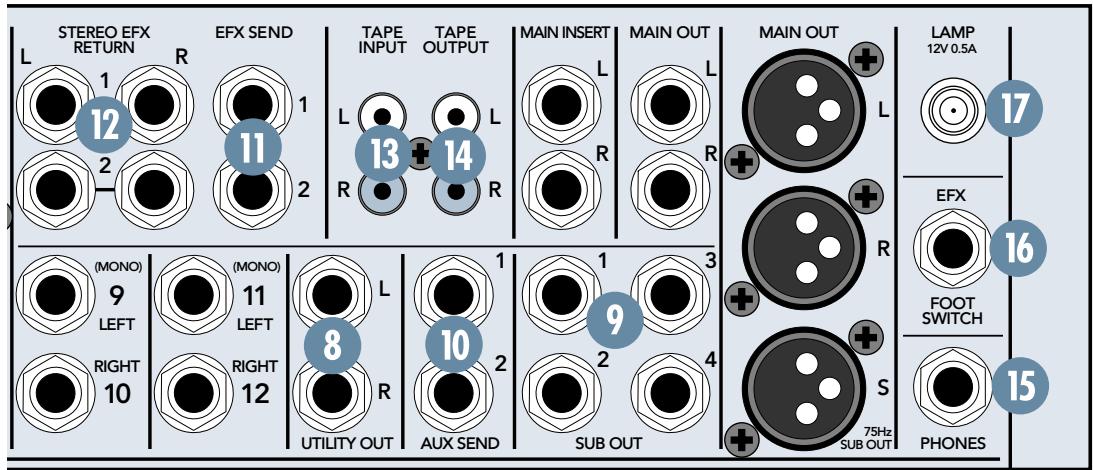
13 TAPE INPUT
Patch the outputs of your intermission entertainment here. Any line-level mono or stereo device can be used: tape, CD player, television audio, etc. See BREAK SWITCH 40 for more information.
When connecting a mono device (just one cord), you'll need a "Y-splitter" RCA adapter. It turns a mono output cord into two cords; so both the left and right tape input jacks can be patched. This adapter is widely available.
TAPE OUTPUT
Use these jacks to capture the entire performance to tape. The signal at these jacks is the main mix, after the MAIN INSERT ⑦ but before the MAIN MIX Fader ③5 . The main mix signal will be present at these jacks regardless of the position of the MAIN MIX Fader.
15 PHONES
The stereo signal at these jacks is the same as at the MAIN OUT 5, but with two important differences:
After the MAIN MIX Fader 35, the mix is sent through the PHONES LEVEL 41 control, allowing you to set levels as desired, without disturbing the main mix level.
When a channel's SOLO PFL 34 is engaged, the main mix signal at this output will be replaced by the solo signal, allowing the engineer to audition channels without disturbing the main mix.
The stereo PHONES jack will drive any standard headphones to very loud levels. Walkperson-type phones can also be used with an appropriate adapter.
Note: Please see the "Safety Instructions" on page 2 for information on hearing protection.
EFX FOOT SWITCH
You can connect a normally-open foot switch to this connector to duplicate the function of the BYPASS 56 switch, located in the EMAC EFFECTS PROCESSOR 48. Closing the switch connection causes the EFX BYPASS indicator to light and mutes the effects.
Note: When a foot switch is plugged into the FOOT SWITCH jack, the BYPASS switch is disabled.
Just like the BYPASS 56 switch, this affects only the internal EMAC EFFECTS PROCESSOR and not any device plugged into STEREO EFX RETURN 2 12.
LAMP
This BNC-type connector will accept almost any of the widely available 12VDC 0.5 amp gooseneck lamps, made by Littlite® and others. If your work involves mixing in the back of dark theaters, this lamp will likely become your best friend.
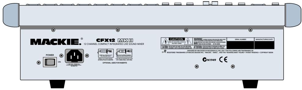
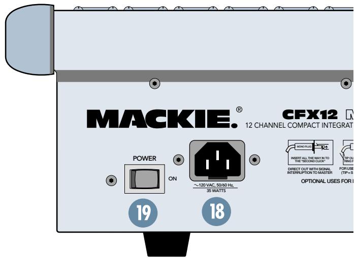
AC POWER INPUT
This IEC Socket is where you connect the supplied AC linecord to provide AC power to the CFX mixer. Plug the cord into a suitable AC outlet, properly grounded and capable of delivering adequate current.
If you happen to lose the AC linecord, replacements are available at any office/computer supply store.
19 POWER SWITCH 20 POWER STATUS
The POWER switch is located on the rear panel, adjacent to the AC Power Input. Push the side of the switch labeled "ON" to turn the mixer on; you should see the POWER STATUS LED glow in confirmation. To turn the mixer off, push the switch the other way. (Let's all say a big collective "Duh.")

Mono Channel
CHANNEL STRIP FEATURES
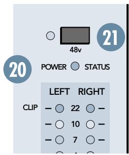
2 PHANTOM POWER
Ha! We tricked you! The phantom power switch is not located in the channel strip section at all! It's way over on the right side of the mixer (see graphic on previous page). We're just mentioning it here since it applies to the channels; specifically, what type of microphones you have plugged into them.
Push in this switch to provide phantom power to the XLR MIC input jacks. All of the XLR mic inputs are capable of providing phantom power. Phantom power is required to operate most condenser microphones (some condenser microphones are battery-powered). The CFX MKII mixers provide +48VDC phantom powering on pins 2 and 3 of the XLR connectors.
If you have dynamic, ribbon, or tube mics that do not require phantom power, leave the PHANTOM POWER switch out. If you are using both condenser and dynamic mics, don't worry. Phantom power will not hurt most dynamic mics. Check the microphone's user manual if you're not sure.

Caution: Turn all output levels down before operating this switch to avoid the possibility of a "pop" in your speakers.
Connecting an external line-level device to an XLR input connector with the phantom power switched on could damage the device. We recommend using the LINE IN 2 and STEREO LINE IN 4 jacks for connecting line-level signals.
22 GAIN
If you haven't already, please read the "SET THE LEVELS" portion of "QUICK START," on page 5.
GAIN adjusts the input sensitivity of the mic and line inputs connected to the channels, mono and stereo. This allows signals from the outside world to be adjusted to optimal internal operating levels.
If the signal originates through a mono channel's MIC 1 XLR jack, there will be 5 dB of gain with the knob fully down, ramping to 50 dB of gain fully up.
Through a mono channel's LINE IN TRS input, there is 15 dB of attenuation fully down and 30 dB of gain fully up, with a "U" (unity gain) mark at 12:00 (knob halfway up).
Through a stereo channel's stereo LINE IN TRS inputs, there is 20 dB of attenuation fully down and 20 dB of gain fully up, with a "U" (unity gain) mark at 12:00 (knob halfway up).
Having 20 dB of line-level attenuation can be very handy when you are injecting a signal that is very hot, when you want to add a lot of EQ boost, or both. Without this "virtual pad," it would be very difficult to control the signal and might lead to channel clipping.
ZERO LEVEL
This handy LED, which (we hope) you already read about in "QUICK START," is triggered to glow when it receives an audio signal at or above 0 dBu.
If the LED is glowing, as opposed to flickering, turn the GAIN 22 down. If the LED is doing almost nothing, turn the GAIN up.
For a more accurate method of setting gain levels, please see RUDE SOLO (page 15), where a soloed signal will appear on the mixer's meters.
24 LOW CUT
The LOW CUT switch, often referred to as a high pass filter (depends on how you look at it), cuts bass frequencies below 100Hz at a rate of 18 dB per octave.
We recommend that you use LOW CUT on every microphone application except kick drum, bass guitar, or bass-heavy synth patches. LOW CUT can also help reduce the possibility of feedback in live situations and it helps to conserve amplifier power.
25 AUX
These knobs tap a portion of each channel signal and send it out, via the AUX SEND ⑩ jacks, to an external device for parallel effects processing or stage monitoring.
AUX levels are controlled by these AUX knobs and by the AUX MASTER SENDs 45. These are more than mere effects and monitor sends: they can be used to generate separate mixes for recording or "mix-minuses" for broadcast.
Each AUX knob's level ranges from off through unity (the center detent position) on up to 15 dB of extra gain (fully clockwise).
The line-level stereo channels' AUX knobs control a mono sum of the channel's stereo signals. For instance, on the CFX20, channel 17 (L) and 18 (R) mix together to feed that channel's AUX send knobs.
PRE FADER
The aux send rule of thumb: For parallel effects processing, use aux sends in post-fader mode. For stage monitors, use pre-fader mode (see diagram below).
With this switch disengaged (up), AUX 1 and 2 receive signals in post-fader mode: post-low cut, post-insert, post-EQ, post-mute, and POST-fader. Any changes made to the channel controls will affect the AUX signal.
With this switch engaged (down), AUX 1 and 2 receive signals in pre-fader mode: post-low cut, post-insert, post-EQ, post-mute, and PRE-fader. Any changes made to the channel controls, EXCEPT the fader, will affect the AUX signal.
In pre-fader mode, you can take the drummer's vocals out of the main mix by turning his fader down, but since he still hears himself in the monitors, he's happy.
2 EFX 1 (EXT)
EFX 1, designed for feeding the inputs of parallel effects devices, behaves exactly like an AUX 25 send, but it's always in post-fader mode: Any changes made to the channel controls will affect the EFX signal. The PRE FADER 26 switch has no effect on the EFX sends.
28 EFX 2 (INT)
EFX 2 is identical to EFX 1 with one big difference: In addition to feeding the EFX SEND
jacks, it also feeds the inputs to the EMAC EFFECTS PROCESSOR 48. If you're using EMAC and just one outboard processor, patch the outboard processor via EFX RETURN 1. You can use EMAC and an outboard device via EFX 2; just remember that the sends (EFX 2 (INT)
28, EFX 2 SEND 49) and returns (TO MAIN MIX 50) control two devices. The PRE FADER
26 switch has no effect on the EFX sends; they're always post-fader.
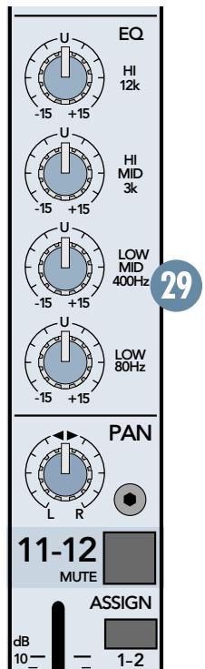
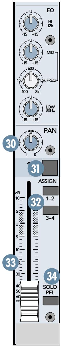
29 EQ
The CFX MKII mixer has low shelving, mid peaking, and high shelving EQ. "Shelving" means that the circuitry boosts or cuts all frequencies past the specified frequency. For example, boosting the LOW EQ knob boosts
bass frequencies at 80Hz and below. "Peaking" means that only a selected "hill" of frequencies surrounding a center "hilltop" frequency is affected by the EQ control.
Everything in moderation (including moderation): with EQ, although you can bring a sound to life, you can also screw things up. If you max the EQs on every channel, you'll get mix mush, not to mention driving your mix levels near or beyond clipping. So equalize subtly; use the left sides of the knobs (cut) as well as the right (boost).
HI EQ
This control provides up to 15 dB of boost or cut at 12kHz and above, and it is also flat at the detent. Use it to add sizzle to cymbals or an overall sense of transparency or edge to keyboards, vocals, guitar, and bacon frying. Turn it down a little to reduce sibilance or hide tape hiss.
MID EQ
Short for "midrange," this knob provides 15 dB of boost or cut, also flat at the center detent.
Midrange EQ is often considered the most dynamic, because the frequencies that define any particular sound are almost always found in this range. You can create as many interesting and useful EQ changes by turning this knob down as well as up.
The mono channels employ a semi-parametric mid-sweep EQ. In addition to being able to set the amount of boost, you can "aim" that boost at a specific frequency; anywhere from 100Hz to 8kHz .
The stereo channels employ a 2-stage fixed-frequency MID EQ. HI-MID is centered at 3kHz LOW-MID is centered at 400Hz
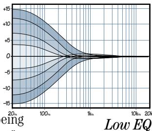
LOW EQ
This control provides up to 15 dB of boost or cut at 80Hz and below. The circuit is flat (no boost or cut) at the center detent position. This frequency represents the punch in bass drums, bass guitar, fat synth patches, and high-testosterone male singers.
When adding boost to the channel's low EQ, simultaneously engaging the LOW CUT switch can create an audible low frequency boost without boosting stage rumble, mic handling clunks, and breath pops.
Stereo Channel
30 PAN
PAN adjusts the amount of channel signal sent, left versus right, to the SUB OUTs 9 (and ultimately the MAIN OUTs 5 via the SUB ASSIGN 44 switches). On mono channels, the knob places the signal somewhere between hard left and hard right. On stereo channels, it works like the balance control on your home stereo, by attenuating one side or the other.
With the PAN knob hard left, the signal will feed SUB 1 and SUB 3 (assuming the channel's ASSIGN 32 switches are engaged).
With the PAN knob hard right, the signal will feed SUB 2 and SUB 4 (assuming the channel's ASSIGN 32 switches are engaged).
With the PAN knob set somewhere in between, the signal will be shared across both sides of the mix.
MUTE
When you engage a channel's mute switch, its signal disappears from these outputs: MAIN OUT 5 , MAIN INSERT 7 , SUB OUT 1-4 9 , AUX SEND 1 & 2 10 , EFX SEND 1 & 2 11 (including the send to the EMAC EFFECTS PROCESSOR 48 ). The only thing it doesn't mute is the channel's SOLO PFL 34 switch, so you can audition channels, via headphones, without sending them to the main mix.
2 ASSIGN
Used in conjunction with the PAN ③ 0 knob, ASSIGN determines the final destination of a channel's signal. Engaging ASSIGN 1- 2, for instance, sends that channel's signal to the SUB 1 and 2 Faders 43 and, via their SUB ASSIGN ④ switches, the MAIN MIX Fader ⑤
Typically, ASSIGN 1-2 will be engaged on all channels destined for the main mix. By configuring SUB 1 and 2 to feed the main mix, the channel ASSIGN 1-2 switches become the equivalent of being "Main Mix" switches.
Some channels can use ASSIGN 3-4 instead; creating a submix for a set of channels (all the drum channels, for instance). Then, by configuring SUB 3 and 4 to also feed the main mix, you can "ride" the SUB 3 and 4 Faders independently of the rest of the mix.
SUB Faders 43, SUB ASSIGN 44, and MAIN MIX Fader 35 will explain this further.
3 FADER
Although the most self-explanatory item on a mixer, we'll explain it anyway: The fader is the master level control for the channel's sig
nal. Subtle adjustment of the channels' fader positions is the key to a finely-tuned mix.
Typically (providing the GAIN 22 knob is set correctly) the fader position will be positioned somewhere between 0 dB ("U") and -30dB .
If you have a fader set all the way up, adding 10 dB of gain, that's usually a sign that your GAIN knob is set too low. Conversely, if the fader is set way down, your GAIN may be set too high.
"U" LIKE UNITY GAIN

Mackie mixers have a "U" symbol on almost every level control. This "U" stands for "unity gain," meaning no change in signal level. Once
you have adjusted the input signal to line-level, you can set every control at "U" and your signals will travel through the mixer at optimal levels. What's more, all the labels on our level controls are measured in decibels (dB), so you'll know what you're doing level-wise if you choose to change a control's settings.
SOLO PFL
Engaging a channel's SOLO switch causes this dramatic turn of events: The PHONES ⑤ and Meters 36 , which ordinarily receive the main mix signals, instead receive the SOLO PFL signal. PFL, being a mono signal, is sent to both sides of the PHONES outputs and to the LEFT meter. Additionally, the RUDE SOLO ③ 7 LED flashes obnoxiously to remind you that "you're in solo."
The SOLO PFL signal is tapped before the channel's MUTE 31 and Fader 33 controls. It does, however, follow GAIN 22, LOW CUT 24, and EQ 29 settings, making it the perfect tool for quick inspections of individual or multiple channels. The channel's PAN 30, MUTE 31 and Fader 33 settings have no effect on the SOLO signal. See RUDE SOLO 37 for more information.

WARNING: Pre-fader SOLO taps the channel signal before the fader 33 If you have a channel's fader set well below "U"
(unity gain), SOLO won't know that and will send a unity gain signal to the PHONES output. That may result in a startling level boost in your headphones.
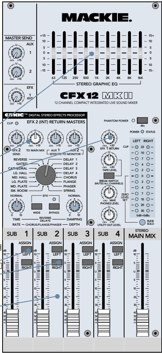
MASTER SECTION FEATURES
We hope you've understood, if not memorized, the CHANNEL STRIP FEATURES you just read. If you're still confused, please look them over again before you tackle this section. Don't worry, it's easy to swallow as long as you take it a bite at a time.
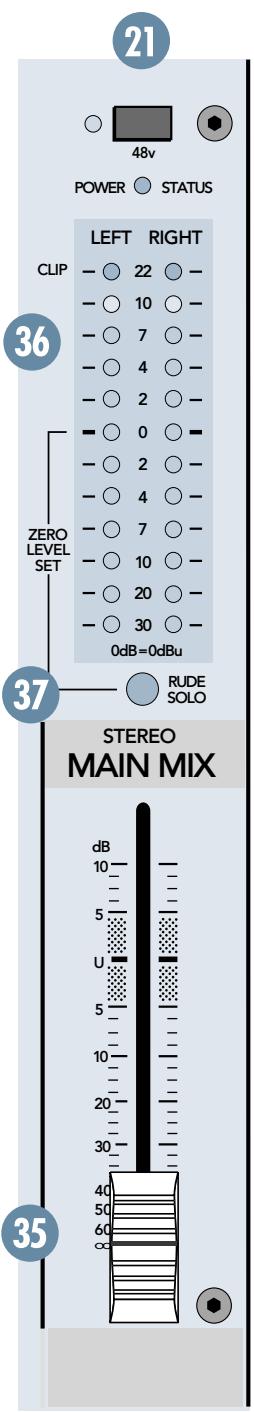
35 MAIN MIX FADER
As the name implies, this stereo fader controls the levels of signals sent to the main outputs: XLR and TRS MAIN OUT 5. The TAPE OUTPUT 4 RCA jacks also receive the main mix, but before the MAIN MIX Fader.
Signals feeding the MAIN MIX Fader, after passing through the STEREO GRAPHIC EQ 38, include: SUB ASSIGN 44 , MAIN INSERT 7 , STEREO EFX RETURN 1 and 2 12 (including the EMAC EFFECTS PROCESSOR 48 ), and TAPE INPUT 13 . All assigned SUB Faders 43 and EFX RETURNS 47 50 that are not turned fully down will appear in the MAIN MIX.
The fader, set fully up, provides 10 dB of gain. A "U" unity gain point is just below that. When set fully down, the main mix is effectively muted. This is the fader to pull down at the end of the song when you want The Great Fade-Out.
36 METERS
The CFX mixer's peak metering system is made up of two columns of twelve LEDs each, with thresholds ranging from -30dB up to "CLIP" (+22dBu at the TRS MAIN OUT ⑤ +28dBu at the XLR MAIN OUT). The meters display the main mix, post MAIN MIX Fader ③ 5 , unless a SOLO PFL ③ 4 switch is engaged.
When a SOLO PFL 34 switch is engaged, the meters will instead display the solo information, at unity gain (pre channel fader 33). Why, you ask? The meters, being a tool for the engineer, must display what the engineer is listening to via the PHONES 15 output.
You can get a good mix with the meter's peaks flashing anywhere between -20 and +10 dB. Most amplifiers clip at about +10 dB, and some recorders aren't so forgiving either. For best real-world results, try to keep your peaks between "0" and "+"

You may already be familiar with +4 (+4dBu = 1.23V) and -10 (-10dBV = 0.32V) operating levels. Basically, what determines the operat
ing level is the relative 0 dB VU (or 0VU) chosen for the meters.
A +4 mixer, with a +4 dBu signal pouring out the back, will actually display 0 dB on its meters. A -10 mixer, with a -10 dBV signal trickling out, will also display 0 dB. So ... when is 0 dB actually 0 dB? Right now!
At the risk of creating another standard, Mackie's compact mixers address the need of both crowds by calling things as they are: 0 dBu (0.775V) at the output shows as 0 dB VU on the meters. What could be easier? (By the way, the most wonderful thing about standards is that there are so many to choose from.)
37 RUDE SOLO
This infamous flashing LED (Light Emitting Diode) serves two purposes — to remind you that at least one SOLO PFL switch is engaged, and to let you know that you're mixing on a Mackie.
Engaging a SOLO PFL ③ 4 switch affects these features: PHONES ① 5 and Meters ③ 6 No other outputs are affected in any way.
Although the "SET THE LEVELS" section of "QUICK START" (page 5) will get your level-setting tasks accomplished, using the meters in PFL SOLO mode lets you really tune in. Instead of one flickering LED, you can make use of the 12-segment VU display in the meters. How? Just engage a SOLO PFL switch and watch the meters.

WARNING: SOLO is prefader and taps the channel signal before the fader 33. If you have a channel's fader set well below "U"
(unity gain), SOLO won't know that and will send a unity gain signal to the PHONES output. That may result in a startling level boost in your headphones.
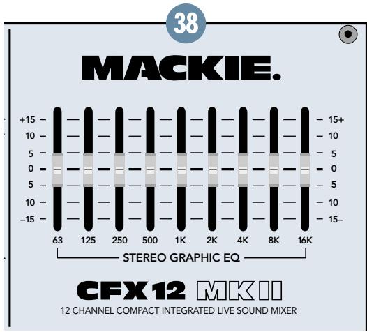
38 STEREO GRAPHIC EQ
This equalizer, used to shape the frequency spectrum of the main mix, is the last thing in the chain prior to the MAIN MIX Fader 35 and MAIN OUT 5 XLR and TRS jacks.
Although there is no actual bypass switch for the STEREO GRAPHIC EQ, by setting all the sliders to zero (center) you'll effectively remove it from the signal path.
How to find and reduce feedback:
- Set the GRAPHIC EQ sliders to zero (center).
- Set the GAIN 22 levels, using the ZERO LEVEL 23 or SOLO PFL 34
- Slowly turn up the MAIN MIX Fader ③5 until feedback just begins to occur. BE CAREFUL! Feedback can occur quickly and become very LOUD, very fast.
- Cut the appropriate slider until feedback stops.
Suggestions for better sound:
- For better vocal sound, set the 125, 250, and 16K sliders to +5.
Note: Make sure the singer is within 3 to 6 inches of the microphone. No amount of EQ can save a wandering minstrel. - For more presence, set the 4K and 8K sliders to +5.
- To warm up the overall sound, set the 2K slider to -5.
- REMEMBER, LESS IS BETTER.
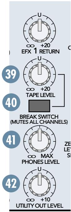
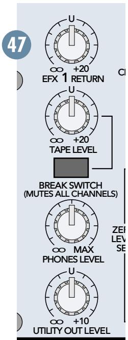
39 TAPE LEVEL
You can adjust the incoming level of your intermission entertainment, independent of the main mix level controls, via this feature. Here's how: Patch the stereo device into the TAPE INPUT 3 . Put the device in play. Engage the BREAK SWITCH 40 and set the TAPE LEVEL 39 knob as desired. Assuming the MAIN MIX Fader 35 is set, you should hear the device.
BREAK SWITCH
No, when we say BREAK SWITCH, we're not asking you to break the switch, we're offering you a very handy feature. When it's time for the talent to take a break, the engineer usually wants to stretch his legs. But walking away from a live mixer in a crowded club can be somewhat unnerving — what if some goon starts dinking around with the faders?
No problem. Just plug in your intermission entertainment device to the TAPE INPUT 13
jacks and engage the BREAK SWITCH. Instantly, the entire main mix is switched off and the intermission entertainment is switched on.
Even if you just want silence during the breaks, this switch can act as a "Master Mute" switch, simply by plugging nothing into TAPE INPUT 13.
PHONES LEVEL
After the MAIN MIX Fader 35, the mix is sent through this knob, allowing you to set headphone levels as desired without disturbing the main mix level.
When a channel's SOLO PFL 34 is engaged, the main mix will be replaced by the solo signal, allowing the engineer to audition channels without disturbing the main mix.
The stereo PHONES jack 15 can drive any standard headphones to very loud levels. Walkperson-type phones can also be used with an appropriate adapter.
Note: Please see the "Safety Instructions" on page 2 for information on hearing protection.
42 UTILITY OUT LEVEL
After the MAIN MIX Fader 35, the mix is sent through this knob, allowing you to set the levels at the UTILITY OUT 8 as desired without disturbing the main mix level.
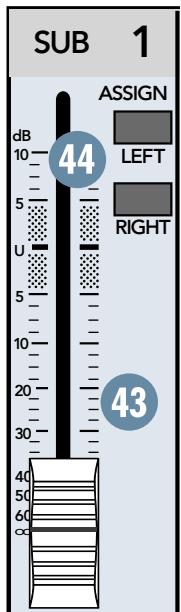
SUB FADERS
The typical exit for channel signals is through one or more sub mixes. The sub mix signal is first controlled by this fader, which provides 10 dB of gain fully up, unity gain at the "U" mark, and is effectively muted fully down.
From here, the signal goes to two very different locations: SUB OUT 9 sends the sub mix directly out of the mixer via its TRS jacks; and SUB ASSIGN 44 sends it to the MAIN MIX Fader 35.
LEFT/RIGHT SUB ASSIGN
As discussed in ASSIGN 32, the only way to get channel outputs to the main mix is via the sub mixes, and this switch is the key.
Continuing the assumption made in ASSIGN 32, Subs 1 and 2 are the left-right stereo path from the channels to SUB Faders 43 1 and 2, with SUB 1 carrying the left signal and SUB 2 carrying the right. Engage SUB 1 ASSIGN LEFT and SUB 2 ASSIGN RIGHT, and you're done. Take a look at the block diagram on page 22—it'll explain this and more, but in hieroglyphics.
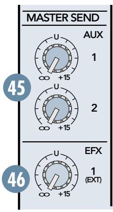
AUX MASTER SEND
Aux send signals are derived by each channel's AUX 25 knob, mixed together, then sent through this AUX MASTER SEND knob. Turned fully up, it provides 15 dB of additional gain, the center "U" mark is unity gain, and fully down is off.
Typically, when the talent (or lack thereof) wants a louder monitor mix, this is the knob to crank up — watch out for feedback!
EFX 1 MASTER SEND
Effects send signals are derived by each channel's EFX 1 (EXT) knob, mixed together, then sent through this EFX 1 MASTER SEND knob. Turned fully up, it provides 15 dB of additional gain, the center "U" mark is unity gain, and fully down is off.
Being that this controls only post-fader sends destined for outboard effects devices, you'll typically set this knob near the "U" mark and then leave it alone.
EFX 1 RETURN
Stereo signals come through the EFX 1 RETURN and continue on to the MAIN MIX Fader ③ . They contain the effects' "wet" signals to be mixed together with the channels' "dry" original signals. Turned fully up, it provides 15 dB of additional gain, the center "U" mark is unity gain, and fully down is off.
Being that this controls only the return signals of external effects, with their levels already determined by the channels' EFX 1 (EXT) knob, you'll typically set this knob near the "U" mark and then leave it alone.
ING/DEPTH 54 and WIDE 55. When you find an effect you like, jot down the parameters, then goof around some more.
To mute these effects, engage BYPASS 56 (or your foot switch if connected to EFX FOOT SWITCH 16). To send these effects to the stage monitor cues, turn up the EFFECTS TO MONITOR 51 knobs.
FOR THE CURIOUS:
E M A C^TM stands for Extended Multiply and Accumulate, which is a proprietary 32-bit digital stereo processor developed by our Digital Engineering Group. It provides 16 preset digital effects algorithms for you to select. In addition to the presets, there are two parameter controls (53 54) you can adjust to change the sound and make it unique for your particular application.
EFX 2 SEND
This controls the signal level being sent to the input of the EMAC module (and to the EFX SEND 2 (1) jack). Use the EFX 2 (INT) (28) controls on the individual channels to adjust the amount of each channel's signal you want to go to the EMAC. Leave EFX 2 SEND set at the center "U" position. If you find that you're not getting enough of the effect in the main mix, make sure that the TO MAIN MIX (50) control is turned up at least to unity (the center detent position). It's okay to turn up the EFX 2 SEND some more if you need to. Just make sure the ZERO LEVEL (57) LED never lights more than occasionally. Read on to find out why.
48 EMAC EFFECTS PROCESSOR
FOR THE IMPATIENT:
Set EFX 2 SEND 49 and TO MAIN MIX 50 at the center "U" mark. Assuming you have your basic mix up and running, turn up the EFX 2 (INT) 28, per channel. This feeds in individual amounts of channel signals to the EMAC inputs — you should be hearing the effects as you do this.
Next, goof around with the various parameters: Preset Select 52, TIME/RATE 53, DAMP-
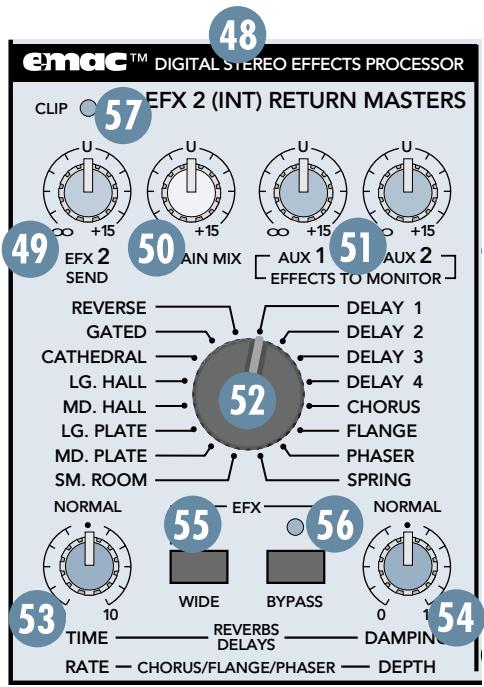
TO MAIN MIX
Stereo signals (from STEREO EFX RETURN 2 and EMAC EFFECTS PROCESSOR 48) come through this TO MAIN MIX knob and continue on to the MAIN MIX Fader 35. They contain the effects' "wet" signals and are mixed together with the channels' "dry" original signals. Turned fully up, it provides 15 dB of additional gain, the center "U" mark is unity gain, and fully down is off.
Being that this controls only the return signals of external and
EMAC effects, with their levels already determined by the channels' EFX 2 (EXT) knob, you'll typically set this knob near the "U" mark and then leave it alone.
5 EFFECTS TO MONITOR
This works just like the channel AUX 25 knobs, but here, the source signal is the EFX 2 RETURN and the EMAC output. Typically, this knob is used to add effects to the stage monitors.
Turned fully up, it provides 15 dB of additional gain, the center "U" mark is unity gain, and fully down is off.
52 PRESET SELECT
Rotate this detented switch to select the preset effect you want to use.
Preset Effects Descriptions
Reverbs
The reverbs are designed to provide a wide variety of reverb sounds for vocal and instrument applications. In the following description, tail refers to the reflections that follow the initial sound event, also referred to as decay range. Pre-delay is the amount of time between the initial sound event and the first reflection.
TIME/RATE 53 controls the length of the tail, with the shortest tail at the 0 position and the longest tail at 10. DAMPING/DEPTH 54 controls the damping, with the darkest tone at 0 and the brightest tone at 10. The WIDE 55 switch is very effective at increasing the stereo image of the reverb effect.
REVERSE: Standard reverse reverb, simulating a tail-first effect
increasing to the original note. Decay range is adjustable from 35 ms to 515 ms. No pre-delay.
GATED: Standard gated reverb, where the reverb tail is cut off sharply after the preset decay length. Decay range is adjustable from 35 ms to 515 ms. No predelay.
CATHEDRAL: Dense, smooth reverb with very long tail, long pre-delay, and late reflections. Tails are very warm with some additional high-end reflections imitating the stone walls of a cathedral.
A very dramatic effect that works well with wind instruments such as flute, slow finger picking on acoustic guitar, and quiet vocal group harmony and choirs. Also works well with keyboards and drums using short decay. Decay range is adjustable from 2 seconds to 10 seconds. Pre-delay set at 75 ms.
LG. HALL: Dense, smooth reverb with long tail, long pre-delay, and some early reflections. Tails are warm with more apparent high end. Works well with vocals and electric and acoustic guitar. Decay range is adjustable from 1 second to 5 seconds. Pre-delay set at 75 ms.
MD. HALL: Dense, smooth reverb with normal tail, normal pre-delay, and increased early reflections. Tails are warm with more apparent high end. Works well with vocals and electric and acoustic guitar. Decay range is adjustable from 750 ms to 2.5 seconds. Pre-delay set at 65ms.
LG. PLATE: Good early reflections and no pre-delay. Tails are normal and warm with strong high end for increased presence. Perfect for vocals and snare. Decay range is adjustable from 1 second to 5 seconds. No pre-delay.
MD. PLATE: Good early reflections and no pre-delay. Tails are short and warm with strong high end for increased presence. Perfect for tight vocals and snare. Decay range is adjustable from 750 ms to 2.5 seconds. No pre-delay.
SM. ROOM: Reverb featuring very fast and scattered early reflections with a short pre-delay. Tails are very short and warm with normal high-end imitating absorbent wall materials and audience. Good for tight vocal effects. Decay range is adjustable from 250 ms to 1 second. Pre-delay set at 30 ms.
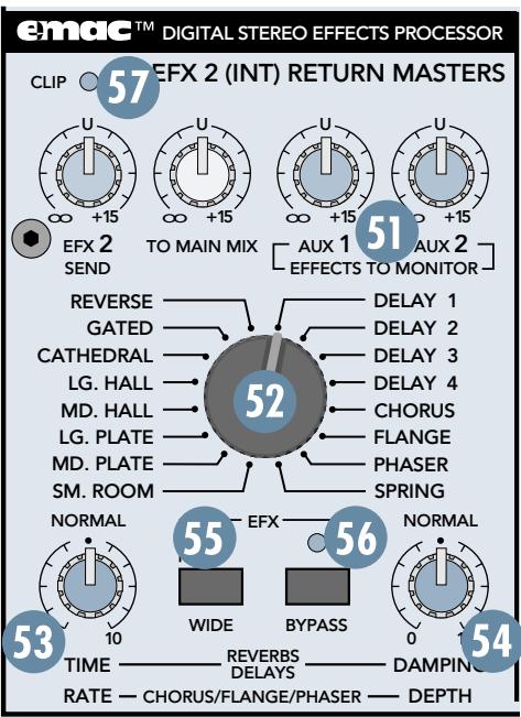
SPRING: Mimics the vintage 60's-style wet spring reverb effect. Tails are normal with strong high end and a slight wa- ver imitating the slow flutter of the mechanical spring system. Very good with acoustic guitar. Decay range is adjustable from 1 second to 5 sec- onds. No pre-delay.
Delays
There are four delays available with one, two, three, and four repeats. TIME/RATE controls the time between repeats, with the fastest repeats at the 0 position and the
slowest repeats at 10. DAMPING/DEPTH ⑤ controls the damping, with the darkest tone at 0 and the brightest tone at 10. Since the delay effect is not stereo, it is not affected by the WIDE ⑤ switch.
DELAY 1: One repeat. Works best for slapback delay used in country and swing guitar, and for rockabilly and some country vocals. Delay range is adjustable from 5 ms to 524 ms.
DELAY 2: Two repeats. Provides a fuller, more dramatic effect for rock and gospel vocals, acoustic guitar, and wind instruments such as flute. Especially effective for some finger-picking styles. Delay range is adjustable from 5 ms to 524 ms.
DELAY 3: Three repeats. An excellent delay for slow, bluesy vocals and melodic flute music. This delay usually works best when the channel EFX send is set at less than halfway. Delay range is adjustable from 5 ms to 524 ms.
DELAY 4: Four repeats. This is for very dramatic delay effects, particularly for enhancing long vocal notes and dramatic instrumental note-chopping effects. Be sure to set the channel EFX send at about halfway. Delay range is adjustable from 5 ms to 524 ms.
Modulation Effects
These include Chorus, Flange, and Phaser, and are generally used for enhancement of instrumental music. However, Chorus adds a dramatic effect to vocals as well. The WIDE
switch is very effective at dramatically increasing the strength and thickness of a modulation effect. For example, using WIDE on Chorus mimics a multi-voiced chorus effect.
TIME/RATE 53 controls the effect Rate, which is the speed of the sweeping effect. Fully counter-clockwise produces the slowest sweeps and fully clockwise produces the fastest.
DAMPING/DEPTH 54 controls the effect depth, which is the strength of the sweeping effect. Fully counter-clockwise produces the lightest sweeping effect and fully clockwise produces the thickest.
CHORUS: Provides a soft, ethereal sweeping effect. Perfect for enhancement of electric and acoustic guitar and bass. Also adds a dramatic effect to vocals, particularly group harmonies and choirs. The channel's EFX 2 (INT) should be set halfway or higher. Rate is adjustable from 0.5Hz to 30Hz . Depth is adjustable from 0% to 100% .
FLANGE: Creates a strong sweeping effect, particularly effective on rock electric guitar, lead and rhythm. The channel's EFX 2 (INT) should be set halfway or higher. Rate is adjust
able from 0.5Hz to 20Hz . Depth is adjustable from 0% to 100% .
PHASER: This effect is perfect for enhancing strummed acoustic guitar or electric guitar power chords. The PHASER effectively duplicates the popular 70's phase shift effect used for guitar. Rate is adjustable from 0.5Hz to 35Hz . Depth is adjustable from 50% to 100% .
TIME/RATE
If you have a reverb effect selected, this control adjusts how long the reverberation lasts, with 0 being a short reverb time and 10 being the longest.
If you have a delay effect selected, this adjusts the amount of time between the original signal and the delayed signal, with 0 being a short delay time and 10 being the longest delay time.
If you have a chorus, flange, or phaser effect selected, this control adjusts the rate or speed of the modulation of the effect.
DAMPING/DEPTH
If you have a reverb or delay effect selected, this control adjusts how fast the higher frequencies roll off in the reverberation or delay, with 0 having little roll off and 10 having the most roll off.
If you have a chorus, flange, or phaser effect selected, this control adjusts the depth of the modulation of the effect.
5 WIDE
Depending on the effect selected, this switch adds more width or depth to the effect. Note that it doesn't work with the DELAY and PHASER effects because they are monophonic.
56 BYPASS
Pushing in this button causes the adjacent EFX BYPASS indicator to light and mutes the effects' output signal. It affects only the internal EMAC effects, not any external effects processor you may have connected to the STEREO EFX RETURN 2 jack.
57 CLIP
This indicates when the EMAC is 6 dB below clipping. Just like the channels' ZERO LEVEL
23 LED, this LED should only light occasionally. If it blinks frequently, you should turn down EFX 2 SEND 49 a little.
GENERAL PRECAUTIONS AND CONSIDERATIONS

NEVER bypass the AC plug's ground pin. This is dangerous!
AC Power Distribution
The majority of AC outlets encountered in homes and clubs (in the U.S.) are served by a 240VAC center-tapped service entrance transformer. This provides two phases of AC power on either side of the center tap, at 120V each.
If lighting is used in a show, it is preferable to power the lights from one leg of the service, and power the audio equipment from the other leg. This will help minimize noise from the lights coupling into the audio (particularly if SCRs, or light-dimmer switches, are used).
In order to minimize ground loops, the safety grounds for all the outlets should be connected to a common ("star") grounding point, and the distance between the outlets and the common grounding point should be as short as possible.
When setting up for a show, oftentimes you are plugging into an AC power distribution system you know nothing about. You may even be faced with 2-wire outlets that are missing the third safety ground pin. It's a good idea to have a three-wire AC outlet tester in your toolbox so you can check the outlets yourself to make sure they are wired correctly. These testers will tell you if the polarity of the hot and neutral wires is reversed and if the safety ground is disconnected. Don't use an outlet if it is wired improperly! This is to protect yourself as well as your equipment.
If you find that you must plug into a two-wire outlet, you will need to use a two-wire to three-wire adapter (cheater plug). These come with a metal tab that you put underneath the center screw that holds the AC outlet faceplate in place. This center screw must be grounded. You can check it by connecting the adapter to the outlet and then plugging in your handy-dandy AC outlet tester.
APPENDIX A: Service Info
Warranty Service
Details concerning Warranty Service are spelled out page 23.
If you think your CFX MKII mixer has a problem, please do everything you can to confirm it before calling for service. Doing so might save you from the deprivation of your mixer and the associated suffering.
Of all Mackie products returned for service (which is hardly any at all), roughly 50% are coded "CND"—Could Not Duplicate, which usually means the problem lay somewhere other than the mixer. These may sound obvious to you, but there's some things you can check. Read on.
Troubleshooting
Bad Channel
- Is the ASSIGN ③ switch set correctly?
- Is the channel Fader 33 turned up?
- On mono channels, try unplugging any INSERT devices.
- Try the same source signal in another channel, set up exactly like the suspect channel.
Bad Output
- Are the SUB ASSIGN 44 switches set correctly?
Are the MAIN MIX Fader 35 and SUB Faders 43 turned up? - If it's one of the MAIN OUTs ⑤ , try unplugging all the others. For example, if it's a TRS MAIN OUT, unplug the associated XLR outputs. If the problem goes away, it's not the mixer.
- If it's a stereo pair, try switching them around. For example, if a left output is presumed dead, switch the left and right cords, at the mixer end. If the left speaker is still dead, it's not the mixer.
Noise
- Turn the channel Faders 33 , EFX 1 RETURN 47 and EFX 2 SEND 49 down, one by one. If the sound disappears, it's either that channel or whatever is plugged into it, so unplug whatever that is. If the noise disappears, it's from your whatever.
Power
- Our favorite question: Is the POWER switch on?
Repair
Service for the CFX MKII Series mixers is available at a factory-authorized service center. Service for Mackie mixers living outside the United States can be obtained through local dealers or distributors.
If your mixer needs service, follow these instructions:
- Review the preceding troubleshooting suggestions. Please.
- Call Tech Support at 1-800-898-3211, 8am to 5pm PST, to explain the problem in detail. If it appears that the mixer needs repair, you will be given a Service Request Number. Have your mixer's serial number ready. You must have an Service Request Number before you can obtain service at a factory-authorized service center.
- Keep this owner's manual and the detachable linecord. We don't need them to repair the mixer.
- Pack the mixer in its original package, including endcaps and box. This is VERY IMPORTANT. When you call for the Service Request Number, please let Tech Support
know if you need new packaging. Mackie is not responsible for any damage that occurs due to non-factory packaging.
- Include a legible note stating your name, shipping address (no P.O. boxes), daytime phone number, Service Request Number, and a detailed description of the problem, including how we can duplicate it.
- Write the Service Request Number in BIG PRINT on top of the box. Product shipped without the Service Request Number will be refused.
- Tech Support will tell you where to ship the mixer for repair. We suggest insurance for all forms of cartage.
- We'll try to fix the mixer within five business days. Once it is repaired, we'll ship it back the same way in which it was received. This paragraph does not necessarily apply to non-warranty service.
Note: You must have a sales receipt from an Authorized Mackie Dealer to qualify for a warranty repair.
APPENDIX B: Technical Info
Specifications
CFX12, CFX16, CFX20 MKII
Mixer Section
Frequency Response
Mic Input to any Output (Gain at 0 dB):
+0,-1dB,32Hzto 20kHz
Distortion
THD and SMPTE IMD; 20Hz to 20kHz
Mic Input to Main Output:
< 0.05% @ +4 dBu output
Noise
20Hz to 20kHz BW (150Ω source impedance)
Equivalent Input Noise (EIN):
-127 dBu
Residual Output Noise:
Main, Monitor, and Effects outputs
Channel & Master levels off
-95 dBu
Common Mode Rejection Ratio (CMRR)
60 dB @ 1 kHz, Gain @ 0 dB
Crosstalk
Adjacent Inputs or Input to Output:
-90 dB @ 1 kHz
Fader Off
-90 dB @ 1 kHz
Mute Switch and Break Switch Mute
-80 dB @ 1 kHz
Input Gain Control Range
Mono Channels
High ±15 dB @ 12 kHz
Mid ±15 dB @ 100 Hz to 8 kHz
Low ± 15dB @ 80Hz
Stereo Channel EQ:
High ±15 dB @ 12 kHz
High Mid ±15 dB @ 3 kHz
Low Mid ±15 dB @ 400 Hz
Low ± 15dB@80Hz
Graphic EQ (9 bands):
Q = 1.414 ISO octave centers
±15 dB @ 63, 125, 250, 500, 1k, 2k, 4k, 8k, 16k Hz
Mixer Rated Output
Main, Sub, Aux, & Efx: +4 dBu
Maximum Rated Output: +20dBu
Maximum Input Levels
Mic Input: -28 dBu, Gain @ +50 dB
+18 dBu, Gain @ +6 dB
Line Input: -8 dBu, Gain @ +30 dB
+38 dBu, Gain @ -15 dB
Insert Input, Stereo Line Input, Tape Input, and
Effects Return: +20dBu
| Maximum Voltage Gain | Input Impedance | ||
| Mic Input to | Mic Input: 3kΩ, balanced | ||
| Insert Output: 50 dB | Line Input: 40kΩ, balanced | ||
| Tape Output: 66 dB | Insert Input, Stereo Line Input, Tape Input, and | ||
| Sub Output: 66 dB | Effects Returns: 10kΩ, unbalanced | ||
| Main Output: 76 dB | Output Impedance | ||
| Aux Send: 71 dB | Main Output, Insert Output, Tape Output, Sub | ||
| Line Input to | Output, and Effects Sends: 150Ω | ||
| Insert Output: 30 dB | Digital Effects | ||
| Tape Output: 46 dB | Resolution: 16-bit, 2-channel | ||
| Sub Output: 46 dB | Number of Presets: 16 | ||
| Main Output: 56 dB | Channel Level Set LED (Sensitivity) | ||
| Aux Send: 51 dB | 0 dBu (normal operating level) | ||
| Stereo Line Input to | VU Meters | ||
| Tape Output: 40 dB | Main L/R | ||
| Sub Output: 40 dB | 12 segments: | ||
| Main Output: 50 dB | Clip, +10, +7, +4, +2, 0, -2, -4, -7, -10, -20, -30 | ||
| Aux Send: 45 dB | Main L/R | ||
| Tape Input to | Disclaimer | ||
| Main Output: 30 dB | Since we are always striving to make our products | ||
| Effects Return to | better by incorporating new and improved materi- als, components, and manufacturing methods, we reserve the right to change these specifications at any time without notice. | ||
| Main Output: 30 dB | |||
Please keep your sales receipt in a safe place.
A. LOUD Technologies Inc. warrants all materials, workmanship and proper operation of this product for a period of three years from the original date of purchase. If any defects are found in the materials or workmanship or if the product fails to function properly during the applicable warranty period, LOUD Technologies, at its option, will repair or replace the product. This warranty applies only to equipment sold and delivered within the U.S. by LOUD Technologies or its authorized dealers.
B. Failure to register online or return the product registration card will not void the three-year warranty.
C. Service and repairs of Mackie products are to be performed only at a factory-authorized service facility (see D below). Unauthorized service, repairs, or modification will void this warranty. To obtain repairs under warranty, you must have a copy of your sales receipt from the authorized Mackie dealer where you purchased the product. It is necessary to establish purchase date and determine whether your Mackie product is within the warranty period.
D. To obtain factory-authorized service:
- Call Mackie Technical Support at 800/898-3211, 7 AM to 5 PM Monday through Friday (Pacific Time) to get a Service Request Number. Products returned without a Service Request Number will be refused.
- Pack the product in its original shipping carton. Also include a note explaining exactly how to duplicate the problem, a copy of the sales receipt with price and date showing, and your return street address (no P.O. boxes or route numbers, please!). If we cannot duplicate the problem or establish the starting date of your Limited Warranty, we may, at our option, charge for service time.
- Ship the product in its original shipping carton, freight prepaid to the authorized service center. The address of your closest authorized service center will be given to you by Technical Support.
IMPORTANT: Make sure that the Service Request Number is plainly written on the shipping carton.
E. LOUD Technologies reserves the right to inspect any products that may be the subject of any warranty claims before repair or replacement is carried out. LOUD Technologies may, at our option, require proof of the original date of purchase in the form of a dated copy of the original dealer's invoice or sales receipt. Final determination of warranty coverage lies solely with LOUD Technologies.
F. Any products returned to one of the LOUD Technologies factory-authorized service centers and deemed eligible for repair or replacement under the terms of this warranty will be repaired or replaced within thirty days of receipt. Products returned to LOUD Technologies that do not meet the terms of this Warranty will not be repaired unless payment is received for labor, materials, return freight, and insurance. Products repaired under warranty will be returned freight prepaid by LOUD Technologies to any location within the boundaries of the USA.
G. LOUD Technologies warrants all repairs performed for 90 days or for the remainder of the warranty period. This warranty does not extend to damage resulting from improper installation, misuse, neglect or abuse, or to exterior appearance. This warranty is recognized only if the inspection seals and serial number on the unit have not been defaced or removed.
H. LOUD Technologies assumes no responsibility for the quality or timeliness of repairs performed by an authorized service center.
I. This warranty is extended to the original purchaser and to anyone who may subsequently purchase this product within the applicable warranty period. A copy of the original sales receipt is required to obtain warranty repairs.
H. This is your sole warranty. LOUD Technologies does not authorize any third party, including any dealer or sales representative, to assume any liability on behalf of LOUD Technologies or to make any warranty for LOUD Technologies Inc.
I. THE WARRANTY GIVEN ON THIS PAGE IS THE SOLE WARRANTY GIVEN BY LOUD TECHNOLOGIES AND IS IN LIEU OF ALL OTHER WARRANTYES, EXPRESS AND IMPLIED, INCLUDING THE WARRANTYES OF MERCHANTABILITY AND FITNESS FOR A PARTICULAR PURPOSE. THE WARRANTY GIVEN ON THIS PAGE SHALL BE STRICTLY LIMITED IN DURATION TO THREE YEARS FROM THE DATE OF ORIGINAL PURCHASE FROM AN AUTHORIZED MACKIE DEALER. UPON EXPIRATION OF THE APPLICABLE WARRANTY PERIOD, LOUD TECHNOLOGIES INC. SHALL HAVE NO FURTHER WARRANTY OBLIGATION OF ANY KIND. LOUD TECHNOLOGIES INC. SHALL NOT BE LIABLE FOR ANY INCIDENTAL, SPECIAL, OR CONSEQUENTIAL DAMAGES THAT MAY RESULT FROM ANY DEFECT IN THE MACKIE PRODUCT OR ANY WARRANTY CLAIM. Some states do not allow exclusion or limitation of incidental, special, or consequential damages or a limitation on how long warranties last, so some of the above limitations and exclusions may not apply to you. This warranty provides specific legal rights and you may have other rights which vary from state to state.
Contributors and Colophon
Manual composed by Jeff Gilbert, the original 10-year Mackoid (not counting Greg, of course). It was created in just 3 hours, using a mascara pencil applied to cocktail napkins in the back booth of a diner in Bothell WA. He then borrowed snippets of text found lying on the floor of Mackie's Engineering and Advertising departments and pasted them in, using cat saliva. It was really quite disgusting, so he turned it all over to Dave Franzwa, a REAL technical writer, to gussy it up.
Additional input provided by Paul Larson, Tech Support guru, Rick Bos, CFX Series Product Manager (and tall, cool guy), and CJ Murray, project engineer. Proofreading provided by honorary Mackoid Linn Compton.
"Mackie," the "Running Man" figure, "CFX," and "EMAC" are trademarks or registered trademarks of LOUD Technologies Inc. All other brand names mentioned are trademarks or registered trademarks of their respective holders, and are hereby acknowledged.
1999-2004 LOUD Technologies Inc. All Rights Reserved.

MACKIE®
16220 Wood-Red Road NE·Woodinville, WA 98072·USA
US and Canada: 800.898.3211
Europe, Asia, Central and South America: 425.487.4333
Middle East and Africa: 31.20.654.4000
Fax: 425.487.4337 • www.mackie.com
E-mail: sales@mackie.com
- CFX MKII SERIES OWNER'S MANUAL
- IMPORTANT SAFETY INSTRUCTIONS
- PORTABLE CART WARNING
- 8, 12, or 16 mono channels, with:
- stereo line channels, with:
- Comprehensive master section, with:
- ABOUT THIS MANUAL
- Absolutely most important page:
- About those blue numbers:
- Please write your serial number here for future reference (i.e., insurance claims, tech support, return authorization, etc.):
- CONTENTS
- QUICK START
- ZERO THE CONSOLE:
- MAKE THE CONNECTIONS:
- SET THE LEVELS:
- TWEAK THE MIX:
- KNOW THESE THINGS:
- PATCHBAY FEATURES
- MIC
- LINE
- INSI
- EFFECTS: SERIAL OR PARALLEL?
- STEREO LINE IN
- MAIN OUT
- SUBWOOFER OUT
- MAIN INSERT
- UTILITY OUT
- SUB OUT
- AUX SEND
- EFX SEND
- STEREO EFX RETURN
- TAPE INPUT
- TAPE OUTPUT
- PHONES
- EFX FOOT SWITCH
- LAMP
- AC POWER INPUT
- POWER SWITCH 20 POWER STATUS
- CHANNEL STRIP FEATURES
- PHANTOM POWER
- GAIN
- ZERO LEVEL
- LOW CUT
- AUX
- PRE FADER
- EFX 1 (EXT)
- EFX 2 (INT)
- EQ
- HI EQ
- MID EQ
- LOW EQ
- PAN
- MUTE
- ASSIGN
- FADER
- "U" LIKE UNITY GAIN
- SOLO PFL
- MASTER SECTION FEATURES
- MAIN MIX FADER
- METERS
- RUDE SOLO
- STEREO GRAPHIC EQ
- Suggestions for better sound:
- TAPE LEVEL
- BREAK SWITCH
- PHONES LEVEL
- UTILITY OUT LEVEL
- SUB FADERS
- LEFT/RIGHT SUB ASSIGN
- AUX MASTER SEND
- EFX 1 MASTER SEND
- EFX 1 RETURN
- FOR THE CURIOUS:
- EFX 2 SEND
- EMAC EFFECTS PROCESSOR
- TO MAIN MIX
- EFFECTS TO MONITOR
- PRESET SELECT
- Preset Effects Descriptions
- Reverbs
- Delays
- Modulation Effects
- TIME/RATE
- DAMPING/DEPTH
- WIDE
- BYPASS
- CLIP
- GENERAL PRECAUTIONS AND CONSIDERATIONS
- AC Power Distribution
- APPENDIX A: Service Info
- Warranty Service
- Troubleshooting
- Bad Channel
- Bad Output
- Noise
- Power
- Repair
- APPENDIX B: Technical Info
- Specifications
- Mixer Section
- Frequency Response
- Distortion
- Common Mode Rejection Ratio (CMRR)
- Crosstalk
- Input Gain Control Range
- Mixer Rated Output
- Maximum Input Levels
- Please keep your sales receipt in a safe place.
- IMPORTANT: Make sure that the Service Request Number is plainly written on the shipping carton.
- Contributors and Colophon
- MACKIE®
Brand : TASCAM
Model : CD-RW 402
Category : CD Recorder