
MIG-200AU - Welding machine Vevor - Free user manual and instructions
Find the device manual for free MIG-200AU Vevor in PDF.
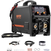


| Product Type | MIG Welding Machine |
| Brand | Vevor |
| Model | MIG-200AU |
| Input Voltage | 220V, 50/60Hz, Single Phase |
| Output Current Range | 50-200A |
| Duty Cycle | 60% at 200A |
| Welding Processes | MIG, Flux-Cored (FCAW) |
| Wire Feed Speed | 1.5-15 m/min |
| Wire Diameter | 0.6-1.0 mm |
| Dimensions (L x W x H) | 520 x 300 x 380 mm |
| Weight | 18 kg |
| Cooling System | Fan Cooling |
| Safety Features | Overheat Protection, Overload Protection |
| Included Accessories | Welding Torch, Ground Clamp, Wire Spool, Face Shield |
| Power Consumption | 5.5 kVA |
| Insulation Class | H |
| Protection Class | IP21 |
| Energy Efficiency | 85% |
| Recommended Materials | Mild Steel, Stainless Steel, Aluminum (with spool gun) |
| Maintenance | Regularly clean nozzle, check wire feed, ensure ventilation |
| Repairability | Repair by authorized service; spare parts available from Vevor |
| Warranty | 1 Year Limited |
Frequently Asked Questions - MIG-200AU Vevor
User questions about MIG-200AU Vevor
0 question about this device. Answer the ones you know or ask your own.
Ask a new question about this device
Download the instructions for your Welding machine in PDF format for free! Find your manual MIG-200AU - Vevor and take your electronic device back in hand. On this page are published all the documents necessary for the use of your device. MIG-200AU by Vevor.
USER MANUAL MIG-200AU Vevor
TechnicalSupport and E-Warranty Certificate www.vevor.com/support
MIG Welder
Model: MIG-200/ MIG-200AU / MIG-250
We continue to be committed to provide you tools with competition "Save Half", "Half Price" or any other similar expressions used by represents an estimate of savings you might benefit from buying tools with us compared to the major top brands and does not mean to cover all categories of tools offered by us. You are reminded to verify carefully when you are placing an order with are actually saving half in comparison with the top major bra
Model: MIG-200 / MIG-200AU / MIG-250

Note: The product picture is for reference, the actual details shall prevail
NEED HELP? CONTACT US!
Have product questions? Need technical support? Please feel free to conta us:
Technical Support and E-Warranty Certificate www.vevor.com/support
This is the original instruction, please read all manual instructions carefully before operating. VEVOR reserves a clear interpretation of our user manual. The appearance of the product shall be subject to the product you receive. Please forgive us that we won't inform you again if there are any technical software updates on our product.
 | Warning-To reduce the risk of injury, user must read instruction manual carefully. |
 | CORRECT DISPOSAL for DisplayThis product is subject to the provision of european Directive 2012/19/EU. The symbol showing a wheelie bin crossed through indicates that the product requires separate refuse collection in European Union. This applies to the product and all accessories marked with this symbol. Products marked as such may not discarded with normal domestic waste, but must be taken to acollection point for recycling electrical and electronic devices. |
 | Compliance is a EC security certification. |
 | FCC Information:CAUTION: Changes or modifications not expressly approved by party responsible for compliance could void the user's authority operate the equipment!This device complies with Part 15 of the FCC Rules. Operati subject to the following two conditions:1) This product may cause harmful interference.2)This product must accept any interference received, including interference that may cause undesired operation.WARNING: Changes or modifications to this product not expre approved by the party.responsible for compliance could void the authority to operate the product.Note: This product has been tested and found to comply with for a Class B digital device pursuant to Part 15 of the FCC These limits are designed to provide reasonable protection aga harmful interference in a residential installation.This product generates, uses and can radiate radio frequency and if not installed and used in accordance with the instructio cause harmful interference to radio communications. However,is no guarantee that interference will not occur in a particular installation. If this product does cause harmful interference to television reception,which can be determined by turning the pro off and on, the user is encouraged to try to correct the inte one or more of the following measures.Reorient or relocate the receiving antenna.Increase the distance between the product and receiver.Connect the product to an outlet on a circuit different from which the receiver is connected.Consult the dealer or an experienced radio/TV technician for assistance. |
Machine Operating Safety
- Do not switch the function modes while the machine is operating. Switching the function modes during welding can damage the machine. Damage caused this manner will not be covered under warranty.
- Disconnect the electrode-holder cable from the machine before switching on machine, to avoid arcing should the electrode be in contact with the work pi
- Operators should be trained and or qualified.
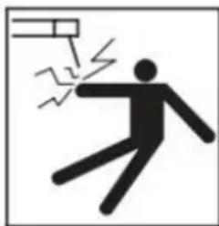
Electric shock: It can kill. Touching live electrical parts can cause fatal shocks or severe burns. The electrode and work circuit is electrically live whenever the output is on. The input power circuit and internal machine circuits are also live when power is on. In MIG/MAG welding, the wire, drive rollers, wire
feed housing, and all metal parts touching the welding wire are electrically live. Incorrectly installed or improperly grounded equipment is dangerous.
- Connect the primary input cable according to Australian and New Zealand standards and regulations.
- Avoid all contact with live electrical parts of the welding/cutting circuit, elect and wires with bare hands.
- The operator must wear dry welding gloves while he/she performs the
welding/cutting task.
- The operator should keep the work piece insulated from himself/herself.
- Keep cords dry, free of oil and grease, and protected from hot metal and
- Frequently inspect input power cable for wear and tear, replace the cable immediately if damaged, bare wiring is dangerous and can kill.
- Do not use damaged, under sized, or badly joined cables.
- Do not drape cables over your body.
- We recommend (RCD) safety switch is used with this equipment to detect leakage of current to earth.
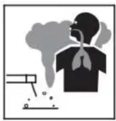
Fumes and gases are dangerous. Smoke and gas generated whilst welding or cutting can be harmful to people's health.
Welding produces fumes and gases. Breathing these fumes and gases can be hazardous to your health. Do not breathe the smoke and gas generated whilst welding or cutting, keep your head on
the fumes
- Keep the working area well ventilated, use fume extraction or ventilation to remove welding/cutting fumes and gases.
- In confined or heavy fume environments always wear an approvedair-supplie respirator.
- Welding/cutting fumes and gases can displace air and lower the oxygen level causing injury or death. Be sure the breathing air is safe.
- Do not weld/cut in locations near de-greasing, cleaning, or spraying operation. The heat and rays of the arc can react with vapours to form highly toxic a irritating gases.
- Materials such as galvanized, lead, or cadmium plated steel, containing elers that can give off toxic fumes when welded/cut. Do not weld/cut these materials unless the area is very well ventilated, and or wearing an air supplied respir

Arc rays: harmful to people's eyes and skin. Arc rays from welding/cutting process produce intense visible and invisible ultraviolet and infrared rays that can burn eyes and skin. Always wear a welding helmet with correct shade offilter lens and suitable protective clothing including welding gloves whilst the
welding/cutting operation is performed.
- Measures should be taken to protect people in or near the surrounding wc area. Use protective screens or barriers to protect others from flash,glare and sparks; warn others not to watch the arc.
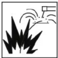
Fire hazard. Welding/cutting on closed containers, such as tanks, drums, or pipes, can cause them to explode. Flying spark from the welding/cutting arc, hot work piece, and hot equipment can cause fires and burns. Accidental contact of electrode to metal objects can cause sparks, explosion, overheating, or fire.
Check and be sure the area is safe before doing any welding/cutting.
- The welding/cutting sparks & spatter may cause fire, therefore remove any flammable materials well away from the working area. Cover flammable material and containers with approved covers if unable to be moved from the welding /cutting area.
- Do not weld/cut on closed containers such as tanks, drums, or pipes, uncle are properly prepared according to the required Safety Standards to insure the flammable or toxic vapours and substances are totally removed, these can cause an explosion even though the vessel has been “cleaned”. Vent hollow casting containers before heating, cutting or welding. They may explode.
- Do not weld/cut where the atmosphere may contain flammable dust, gas, oiliquid vapours (such as petrol)
- Have a fire extinguisher nearby and know how to use it. Be alert that we cutting sparks and hot materials from welding/cutting can easily go through sr cracks and openings to adjacent areas. Be aware that welding/cutting on a c floor, bulkhead, or partition can cause fire on the hidden side.

Gas Cylinders. Shielding gas cylinders contain gas under high pressure. If damaged, a cylinder can explode. Because gas cylinders are normally part of the welding/cutting process, be sure to treat them carefully. CYLINDERS can explode if damaged.
- Protect gas cylinders from excessive heat, mechanical shock physical damage, slag, open flames, sparks, and arcs.
- Insure cylinders are held secure and upright to prevent tipping or falling ov
- Never allow the welding/cutting electrode or earth clamp to touch the gascy do not drape welding cables over the cylinder.
- Never weld/cut on a pressurised gas cylinder, it will explode and kill you.
- Open the cylinder valve slowly and turn your face away from the cylinder valve and gas regulator.

Gas build up. The build up of gas can causes a toxic environment, deplete the oxygen content in the air resulting in death or injury. Many gases use in welding/cutting are invisible and odourless.
- Shut off shielding gas supply when not in use.
• Always ventilate confined spaces or use approved air-supplied respirator.

Electronic magnetic fields. MAGNETIC FIELDS can affect Implanted Medical Devices.
- Wearers of Pacemakers and other Implanted Medical Devices should keep away.
- Implanted Medical Device wearers should consult their doctor
and the device manufacturer before going near any electric welding, cutting o heating operation.

Noise can damage hearing. Noise from some processes or equipment candamage hearing.
- Wear approved ear protection if noise level is high.

Hot parts.Items being welded/cut generate and hold high heat a can cause severe burns.
Do not touch hot parts with bare hands. Allow a cooling period before working on the welding/cutting gun. Use insulated welding gloves and clothing to handle hot parts and prevent burns.
CAUTION
- Working Environment.
i. The environment in which this welding/cutting equipment is installed must be of grinding dust, corrosive chemicals, flammable gas or materialsetc, and at no more than maximum of 80% humidity.
ii. When using the machine outdoors protect the machine from direct sun light water and snow etc; the temperature of working environment should be maintained within -10°C to +40°C .
iii. Keep this equipment 30cm distant from the wall.
iv. Ensure the working environment is well ventilated.
2. Safety Tips.
i. Ventilation
This equipment is small-sized, compact in structure, and of excellent performance in amperage output. The fan is used to dissipate heat generated by this equipment during the welding/cutting operation. Important: Maintain good ventilation of the louvres of this equipment. The minimum distance between this equipment and other objects in or near the working area should be 30 cm. Good ventilation critical importance for the normal performance and service life of this equipment. Thermal Overload protection.
Should the machine be used to an excessive level, or in high temperature environment, poorly ventilated area or if the fan malfunctions the Thermal Overload Switch will be activated and the machine will cease to operate. Und this circumstance, leave the machine switched on to keep the built-in fan work to bring down the temperature inside the equipment. The machine will be rea use again when the internal temperature reaches safe level.
iii. Over-Voltage Supply
Regarding the power supply voltage range of the machine, please refer to “M parameter” table. This equipment is of automatic voltage compensation, which enables the maintaining of the voltage range within the given range. In case the voltage of input power supply amperage exceeds the stipulated value, it is possible to cause damage to the components of this equipment. Please ensure your primary power supply is correct.
iv. Do not come into contact with the output terminals while the machine is operation. An electric shock may possibly occur.
ATTENTION! - CHECK FOR GAS LEAKAGE
At initial set up and at regular intervals we recommend to check for gas leaf. Recommended procedure is as follows:
- Connect the regulator and gas hose assembly and tighten all connectors and clamps.
- Slowly open the cylinder valve.
- Set the flow rate on the regulator to approximately 8-10 L/min.
- Close the cylinder valve and pay attention to the needle indicator of the pressure gauge on the regulator, if the needle drops away towards zero then gas leak. Sometimes a gas leak can be slow and to identify it will require the gas pressure in the regulator and line for an extended time period. In the situation it is recommended to open the cylinder valve, set the flow rate to L/min, close the cylinder valve and check after a minimum of 15 minutes.
- If there is a gas loss then check all connectors and clamps for leakage brushing or spraying with soapy water, bubbles will appear at the leakage point.
- Tighten clamps or fittings to eliminate gas leakage.
IMPORTANT! - We strongly recommend that you check for gas leakage prior operation of your machine. We recommend that you close the cylinder valve the machine is not in use.
TECHNICAL DATA
Gas Metal Arc Welding (GMAW) is an arc welding process where a consumable wire is motor driven feed rolls to a welding gun, an welding current is supplied from the welding source. The welding arc is struck between the piece and the end of the wire, which melts weld pool. The arc and the weld pool are b shielded by gas flow from the gun, or in the case of “self shielded” wires, generated by the wire core. The process is very versatile in that by selection correct wire composition, diameter and shielding gas, it can be used for
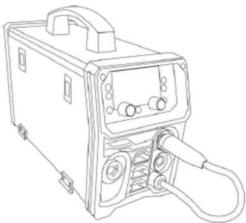
applications ranging from sheet-metal to heavy plate, and metals ranging from carbon steel to aluminum alloys.

| TECHNICAL DATA MIG-200 / MIG-200AU | ||
| Power Supply / Phases | 220V +/- 10%50/60Hz | 220V/110V +/- 10% 50/60Hz |
| Rated input power | MIG:30-200A | MIG:220V:30-200A/110V:30-120A |
| MMA:30-140A | MMA:220V:30-140A/110V:30-120A | |
| TIG:20-140A | TIG:220V:20-140A/110V:20-120A | |
| Duty cycle | MIG: 20% 200A60% 115A / 10089A | 220V: MIG: 20% 200A / 6115A / 100% 89A110V: MIG::20% 120A/ 60% 7100% 54A |
| Feeding mode | ALL IN ONE | ALL IN ONE |
| Wire feeding speed | 2-15M/min | 2-15M/min |
| Welding plate Thickness | 0.5-15mm | 0.5-15mm |
| Welding wire diameter | 0.8-1.2 | 0.8-1.2 |
| TECHNICAL DATA MIG-250 | ||
| Power Supply / Phase | 220V +/- 10%50/60Hz | 220V/110V +/- 10%50/60Hz |
| Rated input power | MIG:30-250A | MIG:220V:30-250A/110V:30-120A |
| MMA:30-160A | MMA:220V:30-160A/110V:30-120A | |
| TIG:20-160A | TIG:220V:20-160A/110V:20-120A | |
| Duty cycle | MIG: 20% 250A / 60145A / 100% 112A | 220V: MIG: 20% 250A60% 145A / 100% 112110V: MIG::20% 120A60% 70A /100% 54A |
| Feeding mode | ALL IN ONE | ALL IN ONE |
| Wire feeding speed | 2-15M/min | 2-15M/min |
| Welding plate Thickness | 0.5-15mm | 0.5-15mm |
| Welding wire diameter | 0.8-1.2 | 0.8-1.2 |
| MIG INSTALLATIONMIG(DCEP) | FLUX-CORED(DCEN) |
 | 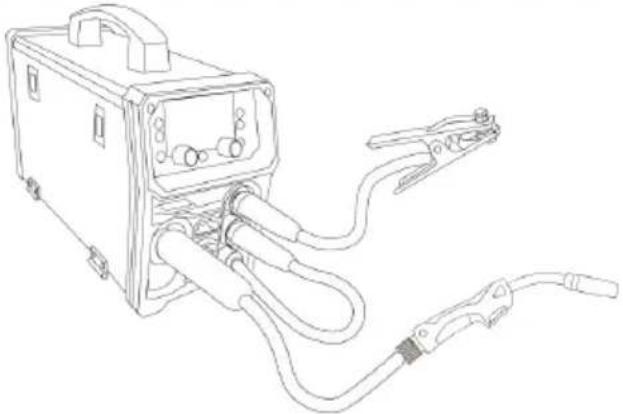 |
- Connect the welding torch into the Euro Mig torch connection socket of front panel, and tighten it.
- Insert the earth cable plug into the required polarity and tighten -negative for gas shielded wires positive for gasless wires. + positive for gas wire. weld power cable goes into the opposing negative or positive socket.
- Connect Gas Line to Gas Regulator and connect the gas regulator to Gas Cylinder. Carefully open the valve of the gas cylinder, set the flow 5l/min.(When using gasless wire)
- Fit the correct type and size of drive rollers (see the chapter of wire roller selection)
- Place the Wire Spool onto the Spool Holder. Feed the wire into the feeder inlet guidetube through to the drive roller.

- At the wire feed assembly, release the compression screw by swiveling outwards. This allows the top roller arm to spring to the open position. The of the welding wire can now be passed through the inlet guide, over the driven roller, and into the output wire guide tube.
- Check that the drive roll groove is correct for the wire in use. The appropriate size is stamped on the visible side of the installed roller. Check also that the correct size contact tip is fitted at the gun end.
- Return the top roller arm to the closed position and adjust the compression screw to provide sufficient clamping of the drive roll to achieve constant feed. Do not over tighten.
- With the equipment energized, operate the gun switch to feed wire thr the gun cable.
We provide 3 kinds of feeding rolls including V-type, U-type and Knurled.
V-type: for carbon steel, stainless steel, or copper welding.
U-type: for aluminum welding
Knurled: for Flux-cored wire welding
Accessories:
MIG-200
- MB15 MIG TORCH x 3m, the kit included 1.0 tip assembled,
- 0.8 tip x 2pcs, 1.0 tip x 2pcs,
- small wrench x1pcs
- Electrode holder x 2m
- Earth clamp x 1.5m
- Self-shielded welding wire(1.0mm) x 1roll
- Mesh hose x2m
- Feeding roll: V-type0.8/1.0 1pcs; Knurled0.8/1.0 1pcs.
- Hose clamp 6/12 x2pcs
- American transition plug 110v-220v 0.3m x1pc (Available for110V/220V models only)
MIG-200AU
- MB15 MIG TORCH x 3m, the kit included 1.0 tip assembled
- 0.8 tip x 2pcs, 1.0 tip x 2pcs
- small wrench x1pcs
- Electrode holder x 2m
- Earth clamp x 1.5m
- Self-shielded welding wire(1.0mm) x 1roll
- Mesh hose x2m
- Feeding roll: U-type1.0/1.2 1pcs; V-type0.8/1.0 1pcs; Knurled0.8/1.0 1pcs.
- Hose clamp 6/12 x2pcs
- American transition plug 110v-220v 0.3m x1pc ( Available for110V/220V models only)
MIG-250
- MB15 MIG TORCH x 3m, the kit included 1.0 tip assembled,
- 0.8 tip x 2pcs, 1.0 tip x 2pcs,
- small wrench x1pcs
- Electrode holder x 2m
- Earth clamp x 1.5m
- Self-shielded welding wire(1.0mm) x 1roll
- Mesh hose x2m
- Feeding roll: U-type1.0/1.2 1pcs; V-type0.8/1.0 1pcs; Knurled0.8/1.0 1pcs.
- Hose clamp 6/12 x2pcs
- American transition plug 110v-220v 0.3m x1pc ( Available for110V/220V models only)
LIFT TIG INSTALLATION
In the TIG (Tungsten Inert Gas) method, the electric arc strikes under an in (argon) shield, between the welded element and the non-fusible electrode made pure tungsten or tungsten with additives.
The TIG method is especially recommended for aesthetic and high-quality join of metals, without laborious mechanical treatment after welding. However, this requires proper preparation and cleaning of the edges of both welded elements. The mechanical properties of the additive material should be similar to the properties of the welded parts. The role of shielding gas is always played by argon, supplied in quantities depending on the welding current set.
TIG(DCEN)

Note: 1, When you do Lift-TIG welding, you need to use external pure argon 2, The Lift-TIG torch is not included in standard package.
-
Connect the welding torch into the Euro Mig torch connection socket on t front panel, and tighten it.
-
Insert the earth cable plug into the positive socket. The TIG torch plug into negative socket.
-
Connect Gas Line from the torch to Gas Regulator and connect the gas regulator to the Gas Cylinder. Carefully open the valve of the gas cylinder, s flow to 5l/min.
4.
MMA INSTALLATION
Arc welding is also called the MMA (Manual Arc Welding) method and is the and most versatile arc welding method.
The MMA method uses a coated electrode, consisting of a metal core covered in a lagging. An electric arc is created between the end of the electrode and the material being welded. Arc ignition is created by touching the electrode with the end of the work piece. The welder feeds the electrode as it melts into the piece so as to maintain a constant arc length and at the same time moves melting end along the welding line. The melting coating of the electrode gives protective gases that protect the liquid metal from the influence of the surround atmosphere, and then solidifies and forms a slag on the surface of the lake, protects the coagulating weld from cooling too quickly and harmful environment influences.
STICK(DCEP)

Connect the welding and mass leads to the appropriate output connectors of welder, according to the polarity recommended by the manufacturer of the electrodes you intend to weld.

| 1 | LED display screen |
| 2 | The welding mode selector, there are 4 modes: MIG-200: MIG manual/MIG SYN/MMA/LIFT TIG MIG-200AU: MIG manual/MIG Pulse/MMA/LIFT TIG |
| 3 | The trigger mode selector for 2T/4T and VRD mode. |
| 4 | The material selector for Iron/Stainless steel/Flux-cored/Aluminum |
| 5 | The welding wire diameter selector, 0.8/1.0/1.2 |
| 6. | The Job recalling button, you can call out the job setting memory saved before |
| 7. | The Job saving button, you can save the current setting data in memory. |
| 8. | The gas selector, pure 2 Dixed gas |
| 9. | The welding voltage adjustment knob, click it enter a loop option: Pre-gas/inductance/Post-gas/peak current setting |
| 10. | The welding current adjustment knob, click it enter a loop option: Pre-gas/inductance/Post-gas/peak current setting |
Weld Mode

MIG(Manual) - The welding voltage can be adjusted individually at a fixed circuit MIG(SYN) - Synergy mode, this is achieved by amperage setting, the machine automatically set the welding voltage and wire feed speed, to the optimal and efficient settings apply to the machine. (Just apply to MIG-200 AU only)
MIG(Pulse) -This mode is especially suitable for aluminum welding, and effect improve the forming effect of welding seams.(Just apply to MIG-200only)
MMA -Stick arc welding mode
TIG (Lift) -Lift-TIG welding mode, on this mode, you should use pure argon
Material Mode

Fe -for carbon steel, mild steel or iron;
Ss- for stainless steel;
Flux –for Flux-cored wire(gasless weld) only;
AI– Aluminum alloy welding, for example AISi, AlMg.
There are 4 selections for different materials, Fe(carbon steel), Ss(stainless steel) Flux(gasless welding), Al(aluminum)
TRIGGER MODE

2T
The 2T light will illuminate when the power source is in 2T welding mode. I mode, the torch trigger must remain pressed (closed) for the welding output to active. See example below: Press and hold the torch trigger to activate the source, the gas valve and gas will flow. After the gas pre flow time ends, I discharge begins and then the welding arc will ignite and then the current rise (slope up time) to the welding current value gradually until you achieve the current welding current. When the torch switch is released, the current begins to drop gradually (slope down time) and when it drops to the minimum current value, welding output is cut off and the gas valve will close, once the post flow time this is the end of the welding process. If the torch switch is pressed down the current downslope period, the current will rise up again to the preset we current value and the slope out process will only start again once the torch to be released.
4T
The 4T light will illuminate when the power source is in 4T welding mode, the trigger mode is mainly used for long welding runs to assist in reducing open finger fatigue. In this mode the user can press and release the torch trigger output will remain active until the trigger switch is depressed again and release In 4T mode, the gas valve opens when the torch switch is pressed down, a pre flow time ends, HF discharge occurs which ignites the welding arc. Once welding arc has successfully ignited the initial current value is active and the switch can now be released, the welding current rises up to the preset weld current value gradually and you will continue to weld your material. To finish welding, simply press the torch switch down again and the current will begin gradually drop (slope out time) to the final current value. When the torch sw released the current output is cut off and the gas will continue to flow until preset post flow time has elapsed.
VRD
Voltage Reduction Devices (VRD) are critical components in the welding indus designed to enhance safety by reducing the open-circuit voltage when the we equipment is not actively in use. Their primary function is to minimize the of electric shock to the welder, which can occur if they come into contact electrode while the equipment is idle.
WIRE DIAMETER
0.8/1.0/1.2
GAS SELECTOR

CO2 100% - This option is only available Fe mode and Ss mode MIXED - This option is only available in F mode and Ss mode
| MIG Welding Current-Wire Diameter And Plate Thickness Chart | ||||||
| Wire diameter | Plate thickness | 1mm | 2mm | 3mm | 4mm | 5mm |
| AL-Si1.0/(4043)(DCEP) | Wire speed (M/min) | 2.0 | 4.2 | 5.8 | 7.0 | 8.5 |
| Welding current (A) | 24 | 58 | 85 | 107 | 133 | |
| Arc voltage | 16.0 | 18.3 | 19.2 | 21.0 | 22.5 | |
| AL-Si1.2/(4043)(DCEP) | Wire speed (M/min) | 1.5 | 3.0 | 4.5 | 6.5 | 7.8 |
| Welding current (A) | 27.0 | 64 | 100 | 143 | 173 | |
| Arc voltage | 16.5 | 17.8 | 19.5 | 22.5 | 24.5 | |
| Al-Mg1.0/(5356)(DCEP) | Wire speed (M/min) | 2.5 | 6.0 | 8.0 | 11.0 | 12.5 |
| Welding current (A) | 30 | 70 | 95 | 130 | 148 | |
| Arc voltage | 14.8 | 18.3 | 19.8 | 22.8 | 23.4 | |
| Al-Mg1.2/(5356)(DCEP) | Wire speed (M/min) | 2.2 | 4.0 | 5.3 | 7.5 | 8.5 |
| Welding current (A) | 33 | 65 | 89 | 128 | 141 | |
| Arc voltage | 15.7 | 17.2 | 17.7 | 19.3 | 20.0 | |
| AL1.0/(1070)(DCEP) | Wire speed (M/min) | 2.8 | 5.3 | 7.0 | 8.5 | 10.0 |
| Welding current (A) | 37 | 77 | 107 | 133 | 160 | |
| Arc voltage | 16.9 | 18.9 | 21.0 | 22.5 | 23.6 | |
| Al-Si 1.2/(1070)(DCEP) | Wire speed (M/min) | 1.7 | 3.2 | 4.0 | 5.8 | 6.9 |
| Welding current (A) | 30.0 | 68.0 | 88.0 | 127.0 | 152.0 | |
| Arc voltage | 16.7 | 18.0 | 18.8 | 21.6 | 22.9 | |
| Cu-Si 1.0/(CuSi) | Wire speed (M/min) | 4.0 | 9.0 | 12.0 | 14.0 | 16.0 |
| (DCEP) | Welding current (A) | 70.0 | 156.0 | 200.0 | 237.0 | 260.0 |
| Arc voltage | 19.0 | 23.8 | 25.5 | 27.0 | 29.0 | |
| Cu-Si 1.2/(CuSi)(DCEP) | Wire speed (M/min) | 2.8 | 5.4 | 6.8 | 8.5 | 9.4 |
| Welding current (A) | 72.0 | 153.0 | 194.0 | 220.0 | 241.0 | |
| Arc voltage | 19.7 | 23.5 | 25.6 | 28.5 | 29.6 | |
| Instruction: Al and Al-Si wire both use Al-Si Function. | ||||||
WELDING POLARITY IN THE TIG METHOD
Negative polarity is used for most TIG welding operations. The welding gun is connected to the negative pole, while the earth gun is connected to the pos pole. In this way, the electrode consumption is reduced, the amount of heat accumulated in the welded material increases.
INFLUENCE OF ARC IN THE TIG LIFT METHOD
To ignite the welding arc in the TIG LIFT method, unscrew the valve on the press the button, then gently rub the tungsten electrode against the workpiece raise the torch lightly so that the arc ignites. Releasing the switch button end welding process (2T).
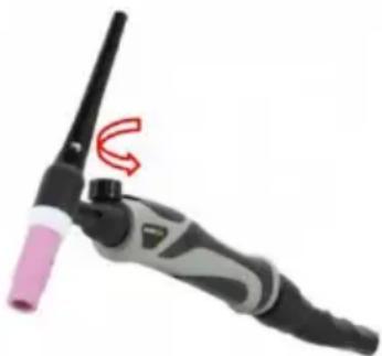
An example of a welding gun for the TIG lift method with a valve in the to
ATTENTION!
The TIG torch is not standard equipment of the set
| TIG WELDING CURRENT AND PLATE THICKNESS CHART | |||
| Tungsten Diameter/ Plate Thickness | 1.6mmAmps. | 2mmAmps. | 2.4mmAmps. |
| 24ga (0.61mm) | 10 | / | / |
| 22ga (0.8mm) | 20 | 20 | |
| 20ga (1.0mm) | 30 | 30 | 30 |
| 18ga (1.024mm) | 40 | 40 | 40 |
| 17ga (1.5mm) | 50 | 50 | 50 |
| 14ga (2.0mm) | 65 | 65 | 65 |
| 1/8"ga(3.0mm) | 80 | 80 | 80 |
| 5/36"ga(4.0mm) | 100 | 100 | 100 |
| 5/36"ga ≥(4.0mm) | / | 100-150 | 100-150 |
MMA SETTING GUIDE
Arc welding is also called the MMA (Manual Arc Welding) method and is the and most versatile arc welding method.
The MMA method uses a coated electrode, consisting of a metal core covered in a lagging. An electric arc is created between the end of the electrode and the material being welded. Arc ignition is created by touching the electrode with the end of the workpiece. The welder feeds the electrode as it melts into the well so as to maintain a constant arc length and at the same time moves its mass along the welding line. The melting coating of the electrode gives off protecting gases that protect the liquid metal from the influence of the surrounding atmosphere, and then solidifies and forms a slag on the surface of the lake, protects the coagulating weld from cooling too quickly and harmful environments influences.
| MMA WELDING ELECTRODE DIAMETER PLATE THICKNESS AND CURRENT DIAMETER | |||
| Eelectrode Diameter/ Plate Thickness | 2.5mm Amps. | 3.2mm Amps. | 4mm Amps. |
| 17ga (1.5mm) | 30 | / | / |
| 14ga (2.0mm) | 50 | 50 | / |
| 1/8"ga(3.0mm) | 70 | 70 | 70 |
| 5/36"ga(4.0mm) | 90 | 90 | 90 |
TROUBLE SHOOTING
| Malfunctions | Solution |
| The meter show nothin Fan does not rotate; No welding output | ➢ Confirm the power switch is on.➢ Power supply available for input cable.➢ Check if the three phase commute bridge is damaged.➢ There is malfunction occurs in the supplementary power source on control board (contact dealers). |
| The meter shows; Fan works normally; No welding output | ➢ Check if all the sockets in the machine are connected well.➢ There is open circuit or badness of connect the joint of output terminal.➢ The control cable on the torch is broken of the switch is damaged.➢ The control circuit is damaged.(contact to dealers) |
| the meter shows;Fan works normally;Abnormal indicator lights. | ➢ It might be over-current protection, please tu off the power switch; restart the machine after abnormal indicator light winked.➢ It might be overheating protection, please wa for about 2-3 minutes until the machine renew without turn off the power switch.➢ It might be multifunction of inverter circuit. (contact dealers) |
| Power indicator light is not on, fan does not turn, no welding press output | ➢ Power switch is broken➢ Verify that the electrical grid connected to t input electromechanical regulations has electricity➢ Enter whether there is a break in the cable |
| The power switch indicator is on and the fan does not turn | ➢ It is possible that the input is misconnected the 380V power supply, causing the over-voltage protection circuit to start, which is changed to 220V power supply, and it can be started aga➢ 220V power instability (too long input line) o input line overlap on the grid,resulting in overv protection➢ Open and close the power switch continuous for a short period of time, causing the over-v protection circuit to start, shut down and wait minutes before starting up again. |
| When the fan turns, the abnormal indicator light is not on and there is high frequency discharge sound, and gas flow from the cutt torch | The vh-07 plug-in voltage of multimeter to panel should be about DC308VThe auxiliary power on MOS panel has a indicator light. If the light is not on, the auxiliary power is not workingControl circuit problem, find the cause or contact the dealer to cut the control line on Cutting gun cable is broken. |
| Output current during cutting is not stable or not controlled by the potentiometer | 1K potentiometers should be replaced if damaged.Poor contact at various joints, especially connectors, shall be checked |
| Abnormal indicator light is not on, high frequent discharge sound, can not cut | It may be overcurrent protection, please turn the machine, and restart the machine after the abnormal light is off.May be overheat protection, do not shut down waiting for 2-3 minutes machine can be restored normal.It may be the inverter circuit fault, please use the power plug of the main transformer on the panel (close to the wind |
MAINTENANCE
Regularly remove dust with clean, compressed air. If the welding machine is working in smoky conditions, in heavily polluted air, remove accumulated dust daily.
The compressed air pressure should be maintained at such a level as not to damage small parts inside the device max. 2-4 bar.
Regularly check the internal systems of the welder, check the correctness and reliability of connections (especially equipment and parts). If you notice rust and loose the connection, remove the rust or oxide coating with sandpaper, recon and tighten.
Avoid situations where water or steam can enter the device. If the welder gets dry it and then check the insulation of the device (also between joints and contacts). After checking that everything is OK, you can continue working.
CIRCUIT

VEVOR®
TOUGH TOOLS, HALF PRICE
Technical Support and E-Warranty Certificate
www.vevor.com/support
- MIG WELDER
- MODEL: MIG-200/ MIG-200AU / MIG
- NEED HELP? CONTACT US
- MACHINE OPERATING SAFETY
- THE FUMES
- CAUTION
- SAFETY TIPS
- VENTILATION
- III. OVER-VOLTAGE SUPPLY
- ATTENTION! - CHECK FOR GAS LEAKAGE
- TECHNICAL DATA
- ACCESSORIES
- MIG
- MIG-200AU
- LIFT TIG INSTALLATION
- TIG(DCEN)
- MMA INSTALLATION
- WELD MODE
- MATERIAL MODE
- TRIGGER MODE
- T
- VRD
- WIRE DIAMETER
- GAS SELECTOR
- WELDING POLARITY IN THE TIG METHOD
- INFLUENCE OF ARC IN THE TIG LIFT METHOD
- ATTENTION
- MMA SETTING GUIDE
- MAINTENANCE
- CIRCUIT
- VEVOR®
Brand : Vevor
Model : MIG-200AU
Category : Welding machine