
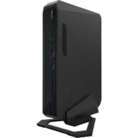
NUC 14 Pro Kit - Mini PC ASUS - Free user manual and instructions
Find the device manual for free NUC 14 Pro Kit ASUS in PDF.
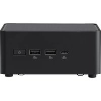


| Product Type | Mini PC |
| Brand | ASUS |
| Model | NUC 14 Pro Kit |
| Processor | 14th Gen Intel Core (up to i7) |
| Memory | Dual-channel DDR5 SO-DIMM, up to 64GB |
| Storage | M.2 NVMe SSD, 2.5" SATA bay optional |
| Graphics | Integrated Intel Iris Xe |
| Connectivity | Wi-Fi 6E, Bluetooth 5.3, 2x Thunderbolt 4, HDMI 2.1, USB 3.2 Gen2, 2.5Gb Ethernet |
| Operating System | None (kit), supports Windows 11 / Linux |
| Dimensions (W x D x H) | 117 x 112 x 51 mm (4.6 x 4.4 x 2.0 in) |
| Weight | 0.7 kg (1.54 lbs) without accessories |
| Power Supply | External 19V DC, 120W adapter |
| Cooling | Active fan, optimized thermal design |
| VESA Mount | Supported (75 x 75 mm) |
| Maintenance | Clean with soft dry cloth; avoid liquids |
| Safety | Keep vents clear; use only provided adapter |
| Spare Parts | RAM, SSD user-upgradeable; other parts via ASUS support |
| Repairability | Easy access to memory and storage; CPU soldered |
| Warranty | 3 years limited (varies by region) |
Frequently Asked Questions - NUC 14 Pro Kit ASUS
User questions about NUC 14 Pro Kit ASUS
0 question about this device. Answer the ones you know or ask your own.
Ask a new question about this device
Download the instructions for your Mini PC in PDF format for free! Find your manual NUC 14 Pro Kit - ASUS and take your electronic device back in hand. On this page are published all the documents necessary for the use of your device. NUC 14 Pro Kit by ASUS.
USER MANUAL NUC 14 Pro Kit ASUS
ASUS NUC 14 Pro/Pro+ Kit/Board/Mini-PC
Technical Product Specification
Regulatory Models: NUC14RVK, NUC14RVH, NUC14RVS, NUC14RVB
February 24'
Revision 1.0
ASUS NUC Boards NUC14RV may contain design defects or errors known as errata that may cause the product to deviate from published specifications. Current characterized errata, if any, are documented in ASUS NUC Board NUC14RV Specification Update.
Revision History
| Revision | Revision History | Date |
| 1.0 | First release of the ASUS NUC 14 Pro/Pro+ Board/Kit Technical Product Specification | February 2024 |
Disclaimer
THIS PRODUCT SPECIFICATION APPLIES TO ONLY THE STANDARD ASUS NUC BOARD NUC14RV WITH BIOS IDENTIFIERS RVMTL357.00XX, RVMTLV57.00XX, OR RVRPLR30.00XX.
No part of this manual, including the products and software described in it, may be reproduced, transmitted, transcribed, stored in a retrieval system, or translated into any language in any form or by any means, except documentation kept by the purchaser for backup purposes, without the express written permission of ASUSTeK COMPUTER INC. ("ASUS").
ASUS PROVIDES THIS MANUAL "AS IS" WITHOUT WARRANTY OF ANY KIND, EITHER EXPRESS OR IMPLIED, INCLUDING BUT NOT LIMITED TO THE IMPLIED WARRANTIES OR CONDITIONS OF MERCHANTABILITY OR FITNESS FOR A PARTICULAR PURPOSE. IN NO EVENT SHALL ASUS, ITS DIRECTORS, OFFICERS, EMPLOYEES OR AGENTS BE LIABLE FOR ANY INDIRECT, SPECIAL, INCIDENTAL, OR CONSEQUENTIAL DAMAGES (INCLUDING DAMAGES FOR LOSS OF PROFITS, LOSS OF BUSINESS, LOSS OF USE OR DATA, INTERRUPTION OF BUSINESS AND THE LIKE), EVEN IF ASUS HAS BEEN ADVISED OF THE POSSIBILITY OF SUCH DAMAGES ARISING FROM ANY DEFECT OR ERROR IN THIS MANUAL OR PRODUCT.
Products and corporate names appearing in this manual may or may not be registered trademarks or copyrights of their respective companies, and are used only for identification or explanation and to the owners' benefit, without intent to infringe.
SPECIFICATIONS AND INFORMATION CONTAINED IN THIS MANUAL ARE FURNISHED FOR INFORMATIONAL USE ONLY, AND ARE SUBJECT TO CHANGE AT ANY TIME WITHOUT NOTICE, AND SHOULD NOT BE CONSTRUED AS A COMMITMENT BY ASUS. ASUS ASSUMES NO RESPONSIBILITY OR LIABILITY FOR ANY ERRORS OR INACCURACIES THAT MAY APPEAR IN THIS MANUAL, INCLUDING THE PRODUCTS AND SOFTWARE DESCRIBED IN IT.
Copyright © 2024 ASUSTeK COMPUTER INC. All Rights Reserved.
LIMITATION OF LIABILITY
Circumstances may arise where because of a default on ASUS' part or other liability, you are entitled to recover damages from ASUS. In each such instance, regardless of the basis on which you are entitled to claim damages from ASUS, ASUS is liable for no more than damages for bodily injury (including death) and damage to real property and tangible personal property; or any other actual and direct damages resulted from omission or failure of performing legal duties under this Warranty Statement, up to the listed contract price of each product.
ASUS will only be responsible for or indemnify you for loss, damages or claims based in contract, tort or infringement under this Warranty Statement.
This limit also applies to ASUS' suppliers and its reseller. It is the maximum for which ASUS, its suppliers, and your reseller are collectively responsible.
UNDER NO CIRCUMSTANCES IS ASUS LIABLE FOR ANY OF THE FOLLOWING: (1) THIRD-PARTY CLAIMS AGAINST YOU FOR DAMAGES; (2) LOSS OF, OR DAMAGE TO, YOUR RECORDS OR DATA; OR (3) SPECIAL, INCIDENTAL, OR INDIRECT DAMAGES OR FOR ANY ECONOMIC CONSEQUENTIAL DAMAGES (INCLUDING LOST PROFITS OR SAVINGS), EVEN IF ASUS, ITS SUPPLIERS OR YOUR RESELLER IS INFORMED OF THEIR POSSIBILITY.
SERVICE AND SUPPORT
Visit our multi-language website at https://www.asus.com/support/.
Preface
This Technical Product Specification (TPS) specifies the board layout, components, connectors, power and environmental requirements, and the BIOS for ASUS NUC Board/Kits NUC14RV. Some features are only available on certain SKUs.
Intended Audience
The TPS is intended to provide detailed, technical information about ASUS NUC Board, Kit, and Mini PCs NUC14RV and its components to the vendors, system integrators, and other engineers and technicians who need this level of information. It is specifically not intended for general audiences.
What This Document Contains
| Chapter | Description |
| 1 | An overview of the features and specifications of the ASUS NUCNUC14RV |
| 2 | The figures, layouts, and physical description of the ASUS NUCNUC14RV Board |
| 3 | Detailed descriptions of the features and specifications |
| 4 | Technical references and considerations |
| 5 | An overview of BIOS features and specifications |
Typographical Conventions
This section contains information about the conventions used in this specification. Not all these symbols and abbreviations appear in all specifications of this type.
Notes, Cautions, and Warnings

NOTE
Notes call attention to important information.

CAUTION
Cautions are included to help you avoid damaging hardware or losing data.
Other Common Notation
| # | Used after a signal name to identify an active-low signal (such as USBPO#) |
| GB | Gigabyte (1,073,741,824 bytes) |
| GB/s | Gigabytes per second |
| Gb/s | Gigabits per second |
| KB | Kilobyte (1024 bytes) |
| Kb | Kilobit (1024 bits) |
| kb/s | 1000 bits per second |
| MB | Megabyte (1,048,576 bytes) |
| MB/s | Megabytes per second |
| Mb | Megabit (1,048,576 bits) |
| Mb/s | Megabits per second |
| TDP | Thermal Design Power |
| xxh | An address or data value ending with a lowercase h indicates a hexadecimal value. |
| x.x V | Volts. Voltages are DC unless otherwise specified. |
| x.x A | Amperes. |
| * | This symbol is used to indicate third-party brands and names that are the property of their respective owners. |
Production Identification Information
ASUS NUC Products NUC14RV Identification Information
| Product Name | ASUS NUC Board | BIOS Revision |
| NUC14RVKC3 | NUC14RVBC3 | RVRPLR30.00xx |
| NUC14RVHC3 | ||
| NUC14RVKU5 | NUC14RVBU5 | RVMTL357.00xx |
| NUC14RVHU5 | ||
| NUC14RVSU5 | ||
| NUC14RVKv5 | NUC14RVBv5 | RVMTLV57.00xx |
| NUC14RVHv5 | ||
| NUC14RVKU7 | NUC14RVBU7 | RVMTL357.00xx |
| NUC14RVHU7 | ||
| NUC14RVSU7 | ||
| NUC14RVKv7 | NUC14RVBv7 | RVMTLV57.00xx |
| NUC14RVHv7 | ||
| NUC14RVSU9 | NUC14RVBU9 | RVMTL357.00xx |
Specification Changes or Clarifications
The table below indicates the Specification Changes or Specification Clarifications that apply to the ASUS NUC Board/Kit/Mini PC NUC14RV.
Specification Changes or Clarifications
| Date | Type of Change | Description of Changes or Clarifications |
Errata
Current characterized errata, if any, are documented in a separate Specification Update. See for the latest documentation.
Online Support
To Find Information About...
ASUS NUC Board/Kit/Mini PC NUC14RV
ASUS NUC Board/Kit/Mini PC Support
High level details for ASUS NUC
Board/Kit/Mini PC NUC14RV
BIOS and driver updates
Tested memory
Integration information
Processor datasheet
Regulatory documentation
Visit this World Wide Web site:
https://www.asus.com/displays-desktops/nucs/nuc-mini-pcs/asus-nuc-14-pro/ https://www.asus.com/displays-desktops/nucs/nuc-mini-pcs/asus-nuc-14-pro-plus/ https://www.asus.com/support/ https://www.asus.com/displays-desktops/nucs/all-series/filter?Category=NUC-Pro https://www.asus.com/support/Download-Center/ https://www.asus.com/support/ https://www.asus.com/support/ https://ark.intel.com https://www.asus.com/support/
Table of Contents
1 Product Description.... 15
1.1 Overview 15
1.1.1 Summary of Mini PC SKUs 15
1.1.2 Summary of Standard Kit and Board SKUs 15
1.1.3 Feature Summary Kits.... 16
2 Product Layout....19
2.1 Board Layout....19
2.1.1 Board Layout (Bottom)....19
2.1.2 Board Layout (Top) 21
2.1.3 Front Panel 22
2.1.4 Back Panel 22
2.1.5 Chassis Expandability Options 23
2.1.6 Block Diagram....24
3 Feature Descriptions 25
3.1 Graphics Subsystem....25
3.1.1 Intel® Arc™ Graphics 25
3.1.2 Intel® Graphics for 14 th Gen Intel Processors....26
3.1.3 Display Emulation....26
3.2 SATA Interface....27
3.3 Real-Time Clock Subsystem 27
3.4 LAN Subsystem....28
3.4.1 RJ-45 LAN Connector with Integrated LEDs....28
3.5 Hardware Management Subsystem....29
3.5.1 Fan Monitoring 29
3.5.2 System States and Power States 29
4 Technical Reference 31
4.1 Connectors and Headers 31
4.1.1 Signal Tables for the Connectors and Headers....31
4.2 Mechanical Considerations....40
4.2.1 NUC 14 Pro Chassis Images....40
4.2.2 NUC 14 Pro+ Chassis Images 42
4.2.3 Form Factor....43
4.3 Thermal Considerations....44
4.4 Reliability....45
4.5 Environmental....46
5 Overview of BIOS Features 48
5.1 Introduction....48
5.2 BIOS Updates 48
5.2.1 BIOS Recovery 48
5.3 Boot Options....49
5.3.1 Boot Device Selection During Post 49
5.3.2 Power Button Menu....49
5.4 Hard Disk Drive Password Security Feature 50
5.5 BIOS Security Features....52
5.6 BIOS Error Messages 53
List of Figures
Figure 1. Major Board Components (Bottom) with Pin 1 Indicators....19
Figure 2. Major Board Components (Top)....21
Figure 3. Front Panel Connectors....22
Figure 4. Back Panel Connectors....23
Figure 5. Back Panel Faceplate 23
Figure 6. Block Diagram....24
Figure 7. LAN Connector LED Locations....28
Figure 8. Connection Diagram for Front Panel Header (2.0 mm Pitch)....34
Figure 9. Location of the BIOS Security Jumper....36
Figure 10. Connection Diagram for the Internal Power Supply Connector 39
Figure 11. Tall Chassis Image Front 40
Figure 12. Slim Chassis Image Front....40
Figure 13. Tall Chassis Image Back Panel 41
Figure 14. Slim Chassis Image Back Panel 41
Figure 13. Pro + Chassis Image Front Panel 42
Figure 14. Pro + Chassis Image Back Panel 42
Figure 15. Board Dimensions....43
Figure 16. Board Height Dimensions....44
List of Tables
Table 1. Feature Summary....16
Table 2. Additional Features ...... 18
Table 3. Components Shown in Figure 1....20
Table 4. Components Shown in Figure 2 ...... 21
Table 5. LAN Connector LED States 28
Table 6. Systems States....29
Table 7. Wake-up Devices and Events....29
Table 8. SATA Combined Data/Power Header....31
Table 9. Internal USB 2.0 Header (1.25 mm pitch)....31
Table 10. M.2 2280 Module (Mechanical Key M) Connector .... 32
Table 11. M.2 2242 Module (Mechanical Key M) Connector ....33
Table 13. Front Panel Header (2.0 mm Pitch)....34
Table 14. States for a One-Color Power LED 35
Table 15. States for a Dual-Color Power LED .... 35
Table 16. BIOS Security Jumper Settings....36
Table 17. Fan Header Current Capability....38
Table 18. Internal Power Supply Connector Pins .... 39
Table 19. Environmental Specifications ....46
Table 20. Acceptable Drives/Media Type for BIOS Recovery....48
Table 21. Power Button Menu Options....49
Table 22. Master Key and User Hard Disk Drive Password Functions....50
Table 23. Supervisor and User Password Functions .... 52
Table 24. BIOS Error Messages....53
1 Product Description
1.1 Overview
1.1.1 Summary of Mini PC SKUs
Product Codes and Ordering information https://www.asus.com/displays-desktops/nucs/all-series/filter?Category=NUC-Pro.
| Processor | Chassis | AC Cord (C5) | RAM | Storage | OS |
| Intel® CoreTM Ultra 9 Processor 185H | Pro+ | US, EU, JP, or No Cord | 2 x 16 GB | 1 TB Gen4 NVMe SSD | Win11 Home |
| Intel® CoreTM Ultra 7 Processor 155H | Pro+ | US, EU, JP, or No Cord | 2 x 16 GB | 1 TB Gen4 NVMe SSD | Win11 Home |
| Intel® CoreTM Ultra 7 Processor 155H | Tall | US, EU, UK, or No Cord | 2 x 16 GB | 1 TB Gen4 NVMe SSD | Win11 Home |
| Intel® CoreTM Ultra 5 Processor 135H | Slim | US, EU, UK, or No Cord | 2 x 8 GB | 512 GB Gen4 NVMe SSD | Win11 Pro |
| Intel® CoreTM Ultra 5 Processor 125H | Pro+ | US, EU, JP, or No Cord | 2 x 8 GB | 512 GB Gen4 NVMe SSD | Win11 Home |
| Intel® CoreTM Ultra 5 Processor 125H | Tall | US, EU, UK, or No Cord | 2 x 8 GB | 512 GB Gen4 NVMe SSD | Win11 Home |
1.1.2 Summary of Standard Kit and Board SKUs
Product Codes and Ordering information https://www.asus.com/displays-desktops/nucs/all-series/filter?Category=NUC-Pro.
| Processor | Chassis | AC Cord (C5) |
| Intel® CoreTM Ultra 9 Processor 185H | Pro+ | US, EU, CN, TW, JP, or No Cord |
| Intel® CoreTM Ultra 7 Processor 165H with Intel® vPro® Technology | Tall | US, EU, UK, AU, TW, or No Cord |
| Board | N/A | |
| Intel® CoreTM Ultra 7 Processor 155H | Pro+ | US, EU, CN, TW, JP, or No Cord |
| Slim | US, EU, UK, or No Cord | |
| Tall | US, EU, UK, AU, CN, TW, JP, or No Cord | |
| Board | N/A | |
| Intel® CoreTM Ultra 5 Processor 135H with Intel® vPro® Technology | Tall | US, EU, UK, AU, TW, JP, or No Cord |
| Board | N/A | |
| Intel® CoreTM Ultra 5 Processor 125H | Pro+ | US, EU, CN, TW, JP, or No Cord |
| Slim | US, EU, UK, or No Cord | |
| Tall | US, EU, UK, AU, CN, TW, or No Cord | |
| Board | N/A | |
| Intel® CoreTM 3 Processor 100U | Slim | US, EU, UK, or No Cord |
| Tall | US, EU, UK, AU, CN, TW, JP, or No Cord | |
| Board |
1.1.3 Feature Summary Kits
Table 1 summarizes the major features of ASUS NUC Board, Kit, and Mini PC NUC14RV
Table 1. Feature Summary
| Board Dimensions | 4.0in by 4.0in (104.1mm by 101.6mm) |
| Max Chassis Dimensions | Pro Slim Chassis: 117mm by 112mm x 37mm (including feet)Pro Tall Chassis: 117mm x 112mm x 54 mm (including feet)Pro+ Chassis: 144mm x 112mm x 41mm (including feet) |
| Processor | ASUS NUC Boards, Kits, and Mini PCs NUC14RV Standard products have a soldered-down 14th generation processor from the list below.Intel® CoreTM Ultra 9 185H ProcessorIntel® CoreTM Ultra 7 165H Processor with Intel® vPro® TechnologyIntel® CoreTM Ultra 7 155H ProcessorIntel® CoreTM Ultra 5 135H Processor with Intel® vPro® TechnologyIntel® CoreTM Ultra 5 125H ProcessorIntel® CoreTM 3 100U ProcessorMore information about Intel® processors can be found athttps://ark.intel.com |
| Memory | Two 262-pin 1.1 V DDR5 SDRAM Small Outline Dual Inline Memory Module (SO-DIMM) socketsSupport for DDR5 4800/5600 MHz SO-DIMMsSupport for 16 Gb and 24 Gb technologySupport for up to 96 GB of system memory with two SO-DIMMs using 48 GB memory modulesSupport for non-ECC memorySupport for 1.1 V JEDEC memory onlyNote: 2 Gb, 4 Gb, and 8 Gb memory technology (SDRAM Density) is not supportedMore information about tested memory can be found athttps://www.asus.com/support/ |
| Graphics | Integrated graphics support for processors with Intel® Graphics Technology:Supports up to quad 4K60Hz displays (2 x DP/Type C + 2 x HDMI 2.1 TMDS)Supports a single 8K60Hz panel, supported by joining two pipes of Displayport (TBT4) over a single portHDR (High Dynamic Range) supportFour display pipes - supporting blending, color adjustments, scaling, and ditheringSupport for HDCP 1.4 and 2.3Codecs supported are detailed in Section 3.1Supporting Persistent Display Emulation on HDMI ports only |
| Audio | The processor supports four High-Definition audio streams on four digital ports simultaneously.The processor supports the following audio formats over HDMI* and DisplayPort*: AC-3 Dolby* Digital, Dolby* Digital Plus, DTS-HD*, LPCM, 192 Khz/24 bit, 6 Channel, and Dolby* TrueHD, DTS-HD Master Audio*.More information about software and drivers can be found athttps://www.asus.com/support/Download-Center/ |
| Storage | One M.2 PCIe Gen4 connector supporting M.2 22x80 (key type M) for NVMe onlyOne M.2 PCIe Gen4 connector supporting M.2 22x42 (key type M) for NVME onlyOne SATA 6.0 Gb/s combined data and power connector for 2.5 inch HDD (on Tall SKUs) |
| Communication | Intel® Wi-Fi 6E1 AX211 (Gig+) M.2 1216 Soldered down module802.11ax R2 2x2, both with 160Mhz channel support + Bluetooth v5.3Maximum transfer speed up to 2.4 GbpsIntel® AMT/vPro support on Core i5 vPro and Core i7 vPro SKUs onlyMore information about Intel® wireless products can be found athttps://ark.intel.comTo obtain drivers visithttps://www.asus.com/support/Download-Center/Gigabit (10/100/1000/2500 Mbps) LAN subsystem using the Intel® i226-LM Gigabit Ethernet Controller (vPro SKUs) and Intel® i226-V Gigabit Ethernet Controller (non-vPro SKUs)PCIe 3.1 5GT/s support for x1 width (Lane)Single-port integrated multi-gigabit (up to 2.5G) - standard IEEE 802.3 Ethernet interface for 2500BASE-T, 1000BASE-T, 100BASE-TX, 10BASE-TE connections (IEEE 802.3, 802.3u, 802.3bz, and 802.3ab)Full wake up support (S4 WOL not supported)Supports for packets up to 9.5 KB (Jumbo Frames)More information about Intel® Ethernet controllers can be found athttps://ark.intel.com |
| ‘ThunderboltTM | 2 x ThunderboltTM ports (back panel)USB4 compliant15W (5V/3A) port bus powerThunderbolt networkingProtocol support:PD Modes Supported: TBT3, USB4, USB3, DP-alt/MFTBT3 Tx/Rx rates: 40G (2x 20.625), 20G (2x 10.3125)PCI Express Tunneling: 32 Gbps (PCI Express* 3.0 x4 compliant)USB4 Tx/Rx rates: 40G (2x 20), 20G (2x 10)USB3 Native: USB 3.2 Gen 2 x1 (10G)USB3 Tunneling: USB 3.2 Gen 2 x1 (10G)USB2: 480 MpbsDP1.4a, HBR3DisplayPort Tunneling:Port 1: 2 streams (~35 Gbps, Thunderbolt 4 certified)Port 2: 2 stream (~35 Gbps, Thunderbolt 4 certified)More information about the location of the ThunderboltTM ports can be found in Section 2.1.4 later in this document |
| USB Ports and Headers | '2 x USB 4 ports via Type C/ThunderboltTM (on back panel, shared with ThunderboltTM as described above)3 x USB 3.2 Gen 2 ports (2 front panel and 1 back panel)1 x USB 2.0 port (1 back panel)2 x USB 2.0 Headers (internal)More information about the location of the USB ports and headers can be found in Section 2 later in this documentMore information about the pinout of the USB ports and headers can be found in Section 4.1 later in this document |
| TPM | Intel® Platform Trust Technology (Intel® PTT) supported on all SKUs - TPM 2.0 CompliantMore information about TPM and Intel® PTT is available onhttps://www.asus.com/support/ |
| Power | AC AdapterCore 3 ships with a 90W 19V adapterCore Ultra 5, Core Ultra 7 ships with a 120W 19V adapterCore Ultra 9 ships with a 150W 19.5V adapterInternal Power Header4-pos/dual row (2x2) right-angled headerPower Input 12VDC to 20VDC+/-5% with DC voltage protection |
| Operating Temperatures | ASUS BIOS provides options to select an External Ambient Temperature Tolerance. Users can select 0-35C, 0-40C, or User Defined. Each option impacts system power, performance, and cooling settings. |
| BIOS | ASUS BIOS resident in the Serial Peripheral Interface (SPI) Flash deviceSupport for Advanced Configuration and Power Interface (ACPI), Plug and Play, and System Management BIOS (SMBIOS) |
| Operating System (Mini PCs only) | ASUS NUC Mini PCs NUC14RV ship with Windows 11 Pro 64-bit, Windows 11 Home Plus 64-bit, or Windows 11 Home preinstalledMore information about available ASUS NUC Mini PCs NUC14RV can be found in Section 1.1.1 Summary of Mini PC SKUs. |
| Hardware Monitor Subsystem | Hardware monitoring subsystem including:Voltage sense to detect out of range power supply voltagesThermal sense to detect out of range thermal valuesOne processor fan headerFan sense input used to monitor fan activityFan speed control |
1 May not be available in all countries
Table 2. Additional Features
| Chassis Expandability and Replaceable Lids | ASUS NUC Mini PCs and Kits NUC14RV ship with a replaceable lid that allows you to replace the cover of the NUC with a full range of cosmetic and functional lidsThe Tall chassis provides a back-panel expansion bay. More information about chassis expandability options can be found in Section 2.1.5 later in this document |
| HDMI CEC API | Built-in support for HDMI CEC is available on both HDMI ports, which may be enabled in the BIOS for display power control, as well as via an API supporting other HDMI CEC functions. |
| Sustained Operation | Qualified for 24x7 sustained operation |
| Auto RTC Reset | A Real-Time Clock (RTC) reset will be triggered after three consecutive unsuccessful boot attempts. |
| Delayed AC Start | Short delay after AC power is applied before unit is ready to power on to protect the system against voltage fluctuations in environments where multiple devices are being powered on simultaneously |
| Reflectivity | All surfaces meet 20GE (20 Gloss Level/Gloss Units) of shininess by measurement of Glanz |
| Kensington Security Slot | Available on the left side of the chassis when viewed from the front on the Pro and on the rear of the chassis on the Pro+ |
| Cable Locking Arm | ASUS NUC Pro Mini PCs and Kits NUC14RV ship with a cable locking arm on the back panel of the chassis. The cable locking arm reduces stress on the power adapter cable in certain positions and prevents unintended losses of power |
| VESA Mount | ASUS NUC Mini PCs and Kits NUC14RV ship with a VESA mount and screws for attaching the system to compatible screens and monitors |
2 Product Layout
2.1 Board Layout
2.1.1 Board Layout (Bottom)
Figure 1 shows the location of the major components on the bottom of ASUS NUC Board NUC14RV.

Figure 1. Major Board Components (Bottom) with Pin 1 Indicators
Table 3. Components Shown in Figure 1
| Item from Figure 1 | Description |
| A | 12-20 V DC Input Jack |
| B | HDMI 2.1 TMDS Port 1 with Built-In CEC Support |
| C | LAN Connector |
| D | Back Panel USB 3.2 Gen 2 / USB 2.0 |
| E | HDMI 2.1 TMDS Port 2 with Built-In CEC Support |
| F | M.2 Retention BIOS Security Header |
| G | Front Panel Header |
| H | Intel® Management Engine BIOS Extension (Intel® MEBX) Reset Header |
| I | M.2 1216 WiFi |
| J | USB 2.0 Headers |
| K | M.2 2280 Module Connector (Key Type M) (NVMe Only) |
| L | USB 3.2 Gen2x2 Type-C (20Gbps) |
| M | M.2 Retention BIOS Security Header |
| N | Front Panel USB 3.2 Gen 2 |
| O | CMOS Battery Connector |
| P | Front Panel USB 3.2 Gen 2 |
| Q | Front Panel Power Button |
| R | DDR4 SO-DIMM 0 Socket |
| S | DDR4 SO-DIMM 1 Socket |
| T | M.2 2242 Module Connector (Key Type M) (NVMe Only) |
| U | Combined Data/Power SATA Connector - Select SKUs only |
| V | BIOS Security Header |
2.1.2 Board Layout (Top)
Figure 2 shows the location of the major components on the bottom-side of ASUS NUC Board NUC14RV.

Figure 2. Major Board Components (Top)
Table 4. Components Shown in Figure 2
| Item from Figure 2 | Description |
| A | Fan and Thermal Solution |
| B | Fan Header |
| C | CMOS Battery |
| D | 12-20 V DC 2x2 Power Connector |
2.1.3 Front Panel

Figure 3. Front Panel Connectors
2.1.4 Back Panel

Item Description
| A | 12-20 V DC Input Jack |
| B | HDMI 2.1 TMDS Port 1 |
| C | LAN Connector |
| D | USB 3.2 Gen 2 Port (blue) / USB 2.0 Port (black) |
| E | HDMI 2.1 TMDS Port 2 |
| ‘F | 'ThunderboltTM Port 2 |
| ‘G | 'ThunderboltTM Port 1 |
Figure 4. Back Panel Connectors
2.1.5 Chassis Expandability Options
The tall chassis provides a back-panel expansion bay that includes a removeable faceplate for when no ports are installed and an internal removeable bracket that is pre-punched for attaching one DB9 port. Some 3 rd party expandability dongles are available from https://gorite.com and a specification is available for the design of 3 rd party add in cards.

Figure 5. Back Panel Faceplate
2.1.6 Block Diagram
![graph TD A["Intel® SoC"] --> B["DDR5 SODIMM 5600MT/s"] A --> C["DDR5 SODIMM 5600MT/s"] A --> D["Intel AX211 WLAN/BTM.2 1216"] A --> E["Front USB 3.2 Gen2x2 Type C"] A --> F["Front USB 3.2 Type A"] A --> G["Front USB 3.2 Type A"] A --> H["Rear USB 3.2 Type A"] A --> I["Rear USB 2.0 Type A"] A --> J["…](/content/2026/07/1499161/images/d83e7c27920586a52d18d1f715ae6b2fc9629baac70f16642e34a5e891d0c781.jpg)
Figure 6. Block Diagram
3 Feature Descriptions
3.1 Graphics Subsystem
ASUS NUC Boards NUC14RV with Core™ Ultra Processors (Core™ Ultra 9/7/5) support Intel® Arc™ Graphics while the NUC14RV with Core™ 3 Processor support Intel® Graphics.
3.1.1 Intel® Arc™ Graphics
Intel® Arc™ Graphics implements a high-performance and low-power HW acceleration for video decoding operations for multiple video codecs.
The HW decode is exposed by the graphics driver using the following APIs:
- Direct3D* 9 Video API (DXVA2), Direct3D11 Video API, Direct3D12 Video API, Intel Media SDK, MFT (Media Foundation Transform) filters, and Intel VA API.
- Intel® Arc™ Graphics supports full HW accelerated video decoding for AVC/HEVC/VP9/JPEG and AVI.
Intel® 14 th Gen Processors implements a low-power low-latency fixed function encoder and high-quality customizable encoder with hardware assisted motion estimation engine which supports AVC, MPEG-2, HEVC, and VP9. The HW encode is exposed by the graphics driver using the following APIs:
- Intel® Media SDK and MFT (Media Foundation Transform) filters.
- Intel® Arc™ Graphics supports full HW accelerated video encoding for AVC/HEVC/VP9/AV1 and JPEG.
There is hardware support for image processing functions such as De-interlacing, Film cadence detection, Advanced Video Scaler (AVS), detail enhancement, gamut compression, HD adaptive contrast enhancement, skin tone enhancement, total color control, Chroma de-noise, SFC (Scalar and Format Conversion), memory compression, Localized Adaptive Contrast Enhancement (LACE), spatial de-noise, Out-Of-Loop De-blocking (from AVC decoder), and 16 bpc support for de-noise/de-mosaic. The HW video processing is exposed by the graphics driver using the following APIs:
- Direct3D* 9 Video API (DXVA2), Direct3D* 11 Video API, OneVPL, MFT (Media Foundation Transform) filters, Intel® Graphics Control Library, and Intel VA API.
Intel® 13 th Gen Processors support the following transcoding features:
- High performance high quality flexible encoder for video editing and video archiving, lower-power low latency encoder for video conferencing, wireless display, and gam streaming, lossless memory compression for media engine to reduce media power, high-quality Advanced Video Scaler (AVS) and low power Scaler and Format Converter.
Notes:
- Resolution support is subject to memory bandwidth availability
- Single 8K at 60 Hz display, supported by monitors that accept dual DP input for tiled screen
3.1.2 Intel® Graphics for 14
th Gen Intel Processors
Intel® Graphics for 14 th Gen Intel Processors features the following:
- DirectX* 12.1 support
- OpenGL* 4.6 support
• Max HDMI resolution 4096x2304 at 60Hz
• Max DP resolution 7680x4320 at 60Hz + - OpenCL* 3.0 support
3.1.3 Display Emulation
Display emulation is supported using the HDMI ports so that the system may be remotely accessed in a headless configuration or be capable of tolerating display connectivity interruptions without the operating system redetecting and rearranging the overall display layout. The display emulation feature may be enabled in BIOS Setup with the following checkboxes:
- "Virtual display emulation": provides a 1280x1024 virtual display when no displays are connected to the system and provides an additional 1280x1024 virtual display if one display is attached to the system. If two displays are attached to the HDMI ports these displays will be enabled and no virtual displays will be provided.
- "Persistent display emulation": emulates that both displays are always connected to the system no matter their actual connection status. The EDID information from each display will remain programmed through S3, S4, S5 and G3 power states until the feature is disabled.
- When "Persistent display emulation" is enabled another drop-down menu ("Inconsistent Display Device") will become visible that allows the user to select the behavior of the system when the display device EDID is inconsistent with the EDID stored by the system.
- "Block boot" (default selection): the BIOS will display a warning message with options and will wait indefinitely for a user selection.
- "Countdown": the BIOS will display a warning message with options and will wait 10 seconds before booting.

NOTE
When using "Persistent display emulation" it would be expected behavior for the system not to properly drive displays different than those connected when the feature was enabled, as the EDID parameters of the initially connected displays are still being driven by the system. In order to retrain the system for different displays, the persistent display emulation feature must be disabled in the BIOS, the system rebooted, and then the persistent display emulation feature must be reenabled.
3.2 SATA Interface
The board provides the following SATA interfaces:
• One SATA 6.0 Gb/s combined Data and Power connector
- Accepts up to 7mm in height 2.5" drives
The PCH provides independent SATA ports with a theoretical maximum transfer rate of 6 Gb/s. A point-to-point interface is used for host to device connections.
3.3 Real-Time Clock Subsystem
A coin-cell battery (CR2032) powers the real-time clock and CMOS memory. When the computer is not plugged into a wall socket, the battery has an estimated life of three years. When the computer is plugged in, the standby current from the power supply extends the life of the battery. The clock is accurate to ±13 minutes/year at 25°C with 3.3 VSB applied via the power supply 5 V STBY rail.

NOTE
If the battery and AC power fail, date and time values will be reset and the user will be notified during the POST.
When the voltage drops below a certain level, the BIOS Setup program settings stored in CMOS RAM (for example, the date and time) might not be accurate. Replace the battery with an equivalent one. Figure 2 on page 21 shows the location of the battery.
System can power on from G3/AC power loss state without the Real-Time Clock battery.
3.4 LAN Subsystem
3.4.1 RJ-45 LAN Connector with Integrated LEDs
Two LEDs are built into the RJ-45 LAN connector (shown in Figure 7).
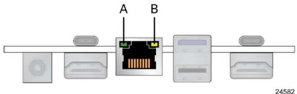
Figure 7. LAN Connector LED Locations
Table 5 describes the LED states when the board is powered up and the LAN subsystem is operating.
Table 5. LAN Connector LED States
| LED | LED Color | LED State | Condition |
| Link | Green | Off | LAN link is not established |
| Solid | LAN link is established | ||
| Blinking | LAN activity is occurring | ||
| Data Rate | Green/Yellow | Off | 10/100 Mb/s data rate is selected |
| Yellow | 1000 Mb/s data rate is selected | ||
| Green | 2500 Mb/s data rate is selected |
3.5 Hardware Management Subsystem
3.5.1 Fan Monitoring
Fan monitoring can be implemented using third-party software.
3.5.2 System States and Power States
Table 6 describes the ACPI states supported by the processor.
Table 6. Systems States
| State | Description |
| GO/S0/C0 | Full On:CPU operating. Individual devices may be shut to save power. The different CPU operating levels are defined by Cx states. |
| GO/S0/Cx | Cx State:CPU manages C-states by itself and can be in lower power states. |
| G1 | Suspend-To-RAM (STR):The system context is maintained in system DRAM, but power is shut to non-critical circuits. Memory is retained and refreshes continue. All external clocks are shut off; RTC clock and international oscillator clocks are still toggling. |
| G1/S4 | Suspend-To-Disk (STD):The context of the system is maintained on the disk. All power is then shut to the system except to the logic required to resume. Externally appears the same as S5 but may have different wake events. |
| G2/S5 | Soft Off:System context not maintained. All power is shut except for the logic required to restart. A full boot is required when waking. |
| G3 | Mechanical Off:System context not maintained. All power shut except for the RTC. No "Wake" events are possible because the system does not have any power. This state occurs if the user removes the batteries, turns off a mechanical switch, or if the system power supply is at a level that is insufficient to power the "waking" logic. |
3.5.2.1 Wake-up Devices and Events
Table 7 lists the devices or specific events that can wake the computer from specific states.
Table 7. Wake-up Devices and Events
| Devices/events that wake up the system... | ...from this sleep state | Comments |
| Power switch | S0iX, S4, S5 1 | |
| RTC alarm | S0iX, S4, S5 1 | Option for monitor to remain in sleep state |
| LAN | S0iX, S5 1,3,4 | “S5 WOL after G3” is supported; monitor to remain in sleep state |
| WIFI | S0iX | |
| Bluetooth | S0iX | |
| USB | S0iX, S4, S5 1,2,3 | Wake S4, S5 controlled by BIOS option (not after G3) |
| PCIe | S0iX, S4 1 | Via WAKE; monitor to remain in sleep state |
| HDMI CEC | S0iX, S4, S5 1 | Wake S4, S5 controlled by BIOS option |
Notes:
- S4 implies operating system support only.
- Will not wake from Deep S4/S5. USB S4/S5 Power is controlled by BIOS. USB S5 wake is controlled by BIOS. USB S4 wake is controlled by OS driver, not just BIOS option.
- Windows Fast startup will block wake from LAN and USB from S5.
- WoL from S4 via Magic Packet is not supported.

NOTE
The use of these wake-up events from an ACPI state requires an operating system that provides full ACPI support. In addition, software, drivers, and peripherals must fully support ACPI wake events.
4 Technical Reference
4.1 Connectors and Headers

CAUTION
Only the following connectors and headers have overcurrent protection: back panel USB Type A and Type C, front panel USB, internal USB headers, internal power header, and DC Vin jack.
All other connectors and headers are not overcurrent protected and should connect only to devices inside the computer's chassis, such as fans and internal peripherals. Do not use these connectors or headers to power devices external to the computer's chassis. A fault in the load presented by the external devices could cause damage to the computer, the power cable, and the external devices themselves.
Furthermore, improper connection of USB header single wire connectors may eventually overload the overcurrent protection and cause damage to the board.
4.1.1 Signal Tables for the Connectors and Headers
Table 8. SATA Combined Data/Power Header
| Pin | Signal Name | Pin | Signal Name |
| 1 | +5V (2A total for pins 1, 2, 3, 4 (0.5A per pin)) | 2 | +5V (2A total for pins 1, 2, 3, 4 (0.5A per pin)) |
| 3 | +5V (2A total for pins 1, 2, 3, 4 (0.5A per pin)) | 4 | +5V (2A total for pins 1, 2, 3, 4 (0.5A per pin)) |
| 5 | NC | 6 | NC |
| 7 | NC | 8 | DEVSLP |
| 9 | GND | 10 | GND |
| 11 | SATA_RX_P | 12 | SATA_RX_N |
| 13 | GND | 14 | SATA_TX_N |
| 15 | SATA_TX_P | 16 | GND |
Connector is vertical 0.5mm contact pitch ZIF FPC/FFC with lock
Table 9. Internal USB 2.0 Header (1.25 mm pitch)
| Pin | Signal Name |
| 1 | 5 V1 |
| 2 | D- |
| 3 | D+ |
| 4 | GND |
1 The two USB 2.0 headers on the board can deliver 1A per port.
Connector is Molex part number 53398-0471, 1.25mm Pitch PicoBlade* Header, Surface Mount, Vertical, Lead-Free, 4 Circuits.
Table 10. M.2 2280 Module (Mechanical Key M) Connector
| Pin | Signal Name | Pin | Signal Name |
| 74 | 3.3V (4A total for pins 74, 72, 70, 18, 16, 14, 12, 4, 2 (0.5A per pin)) | 75 | GND |
| 72 | 3.3V (4A total for pins 74, 72, 70, 18, 16, 14, 12, 4, 2 (0.5A per pin)) | 73 | GND |
| 70 | 3.3V (4A total for pins 74, 72, 70, 18, 16, 14, 12, 4, 2 (0.5A per pin)) | 71 | GND |
| 68 | SUSCLK(32kHz) (O)(0/3.3V) | 69 | PEDET (NC-PCIe) |
| 66 | Connector Key | 67 | N/C |
| 64 | Connector Key | 65 | Connector Key |
| 62 | Connector Key | 63 | Connector Key |
| 60 | Connector Key | 61 | Connector Key |
| 58 | N/C | 59 | Connector Key |
| 56 | N/C | 57 | GND |
| 54 | PEWAKE# (I/O)(0/3.3V) or N/C | 55 | REFCLKP |
| 52 | CLKREQ# (I/O)(0/3.3V) or N/C | 53 | REFCLKN |
| 50 | PERST# (O)(0/3.3V) or N/C | 51 | GND |
| 48 | N/C | 49 | PETp0 |
| 46 | N/C | 47 | PETn0 |
| 44 | N/C | 45 | GND |
| 42 | N/C | 43 | PERp0 |
| 40 | N/C | 41 | PERn0 |
| 38 | DEVSLP (O) | 39 | GND |
| 36 | N/C | 37 | PETp1 |
| 34 | N/C | 35 | PETn1 |
| 32 | N/C | 33 | GND |
| 30 | N/C | 31 | PERp1 |
| 28 | N/C | 29 | PERn1 |
| 26 | N/C | 27 | GND |
| 24 | N/C | 25 | PETp2 |
| 22 | N/C | 23 | PETn2 |
| 20 | N/C | 21 | GND |
| 18 | 3.3V (4A total for pins 74, 72, 70, 18, 16, 14, 12, 4, 2 (0.5A per pin)) | 19 | PERp2 |
| 16 | 3.3V (4A total for pins 74, 72, 70, 18, 16, 14, 12, 4, 2 (0.5A per pin)) | 17 | PERn2 |
| 14 | 3.3V (4A total for pins 74, 72, 70, 18, 16, 14, 12, 4, 2 (0.5A per pin)) | 15 | GND |
| 12 | 3.3V (4A total for pins 74, 72, 70, 18, 16, 14, 12, 4, 2 (0.5A per pin)) | 13 | PETp3 |
| 10 | DAS/DSS# (I/O)/LED1# (I)(0/3.3V) | 11 | PETn3 |
| 8 | N/C | 9 | GND |
| 6 | N/C | 7 | PERp3 |
| 4 | 3.3V (4A total for pins 74, 72, 70, 18, 16, 14, 12, 4, 2 (0.5A per pin)) | 5 | PERn3 |
| 2 | 3.3V (4A total for pins 74, 72, 70, 18, 16, 14, 12, 4, 2 (0.5A per pin)) | 3 | GND |
| 1 | GND |
Table 11. M.2 2242 Module (Mechanical Key M) Connector
| Pin | Signal Name | Pin | Signal Name |
| 74 | 3.3V (4A total for pins 74, 72, 70, 18, 16, 14, 12, 4, 2 (0.5A per pin)) | 75 | GND |
| 72 | 3.3V (4A total for pins 74, 72, 70, 18, 16, 14, 12, 4, 2 (0.5A per pin)) | 73 | GND |
| 70 | 3.3V (4A total for pins 74, 72, 70, 18, 16, 14, 12, 4, 2 (0.5A per pin)) | 71 | GND |
| 68 | SUSCLK(32kHz) (O)(0/3.3V) | 69 | PEDET (NC-PCIe) |
| 66 | Connector Key | 67 | N/C |
| 64 | Connector Key | 65 | Connector Key |
| 62 | Connector Key | 63 | Connector Key |
| 60 | Connector Key | 61 | Connector Key |
| 58 | N/C | 59 | Connector Key |
| 56 | N/C | 57 | GND |
| 54 | PEWAKE# (I/O)(0/3.3V) or N/C | 55 | REFCLKP |
| 52 | CLKREQ# (I/O)(0/3.3V) or N/C | 53 | REFCLKN |
| 50 | PERST# (O)(0/3.3V) or N/C | 51 | GND |
| 48 | N/C | 49 | PETp0 |
| 46 | N/C | 47 | PETn0 |
| 44 | N/C | 45 | GND |
| 42 | N/C | 43 | PERp0 |
| 40 | N/C | 41 | PERn0 |
| 38 | DEVSLP (O) | 39 | GND |
| 36 | N/C | 37 | PETp1 |
| 34 | N/C | 35 | PETn1 |
| 32 | N/C | 33 | GND |
| 30 | N/C | 31 | PERp1 |
| 28 | N/C | 29 | PERn1 |
| 26 | N/C | 27 | GND |
| 24 | N/C | 25 | PETp2 |
| 22 | N/C | 23 | PETn2 |
| 20 | N/C | 21 | GND |
| 18 | 3.3V (4A total for pins 74, 72, 70, 18, 16, 14, 12, 4, 2 (0.5A per pin)) | 19 | PERp2 |
| 16 | 3.3V (4A total for pins 74, 72, 70, 18, 16, 14, 12, 4, 2 (0.5A per pin)) | 17 | PERn2 |
| 14 | 3.3V (4A total for pins 74, 72, 70, 18, 16, 14, 12, 4, 2 (0.5A per pin)) | 15 | GND |
| 12 | 3.3V (4A total for pins 74, 72, 70, 18, 16, 14, 12, 4, 2 (0.5A per pin)) | 13 | PETp3 |
| 10 | DAS/DSS# (I/O)/LED1# (I)(0/3.3V) | 11 | PETn3 |
| 8 | N/C | 9 | GND |
| 6 | N/C | 7 | PERp3 |
| 4 | 3.3V (4A total for pins 74, 72, 70, 18, 16, 14, 12, 4, 2 (0.5A per pin)) | 5 | PERn3 |
| 2 | 3.3V (4A total for pins 74, 72, 70, 18, 16, 14, 12, 4, 2 (0.5A per pin)) | 3 | GND |
| 1 | GND |
4.1.1.1 Front Panel Header (2.0 mm Pitch)
This section describes the functions of the front panel header. Table 12 lists the signal names of the front panel header. Figure 8 is a connection diagram for the front panel header.
Table 12. Front Panel Header (2.0 mm Pitch)
| Pin | Signal Name | Description | Pin | Signal Name | Description |
| 1 | HDD_POWER_LED | Pull-up 750Ω to +5V | 2 | POWER_LED_MAIN | [Out] Front panel LED (main color) Pull-up 300Ω to +5V |
| 3 | HDD_LED# | [Out] HDD activity LED | 4 | POWER_LED_ALT | [Out] Front panel LED (alt color) |
| 5 | GROUND | Ground | 6 | POWER_SWITCH# | [In] Power switch |
| 7 | RESET_SWITCH# | [In] Reset switch | 8 | GROUND | Ground |
| 9 | +5V_DC (1A) (Vcc) | VCC5 (1A current rating) | 10 | Key | No pin |
| 11 | 5Vsby (2A) | 5VSB (2A current rating) | 12 | 3.3Vsby (1A) | 3VSB (1A current rating) |

Figure 8. Connection Diagram for Front Panel Header (2.0 mm Pitch)
4.1.1.1.1 Hard Drive Activity LED Header
Pins 1 and 3 can be connected to an LED to provide a visual indicator that data is being read from or written to a hard drive. Proper LED function requires a SATA hard drive or optical drive connected to an onboard SATA connector.
Pins 5 and 7 can be connected to a momentary single pole, single throw (SPST) type switch that is normally open. When the switch is closed, the board resets and runs the POST.
4.1.1.1.3 Power/Sleep LED Header
Pins 2 and 4 can be connected to a one- or two-color LED. Table 13 and Table 14 show the possible LED states.
Table 13. States for a One-Color Power LED
| LED State | Description |
| Off | Power off |
| Blinking | Standby |
| Steady | Normal operation |
Table 14. States for a Dual-Color Power LED
| LED State | Description |
| Off | Power off |
| Blinking (white) | Standby |
| Steady (white) | Normal operation |

NOTE
The LED behavior shown in Table 13 is default – other patterns may be set via BIOS setup.
4.1.1.1.4 Power Switch Header
Pins 6 and 8 can be connected to a front panel momentary-contact power switch. The switch must pull the SW_ON# pin to ground for at least 50 ms to signal the power supply to switch on or off (the time requirement is due to internal debounce circuitry on the board). At least two seconds must pass before the power supply will recognize another on/off signal.
4.1.1.2 BIOS Security Jumper

CAUTION
Do not move a jumper with the power on. Always turn off the power and unplug the power cord from the computer before changing a jumper setting. Otherwise, the board could be damaged.
Figure 9 shows the location of the BIOS Security Jumper. The 3-pin jumper determines the BIOS Security program's mode.

Figure 9. Location of the BIOS Security Jumper
Table 15 describes the jumper settings for the three modes: normal, lockdown, and configuration.
Table 15. BIOS Security Jumper Settings
| Function/Mode | Jumper Setting | Configuration |
| Normal | 1-2 | The BIOS uses current configuration information and passwords for booting. |
| Lockdown | 2-3 | The BIOS uses current configuration information and passwords for booting, except:All POST Hotkeys are suppressed (prompts are not displayed and keys are not accepted. For example, F2 for Setup, F10 for the Boot Menu).Power Button Menu is not available (see Section 5.3.2 Power Button Menu).BIOS updates are not available except for automatic Recovery due to flash corruption. |
| Configuration | None | BIOS Recovery Update process if a matching *.bio file is found. Recovery Update can be cancelled by pressing the Esc key.If the Recovery Update was cancelled or a matching *.bio file was not found, a Config Menu will be displayed. The Config Menu consists of the following (followed by the Power Button Menu selections):[1] Suppress this menu until the BIOS Security Jumper is replaced.[2] Clear BIOS User and Supervisor Passwords.[3] Reset Intel® AMT to default factory settings.[4] Clear Trusted Platform Module.WARNING! Data encrypted with the TPM will no longer be accessible if the TPM is cleared.[F2] Intel® Visual BIOS.[F4] BIOS Recovery.See Section 5.3.2 Power Button Menu |
4.1.1.3 Intel® Management Engine BIOS Extension (Intel® MEBX) Reset Header
The Intel® MEBX reset header (see Figure 1) allows you to reset the CMOS values to the factory defaults in situations when the system may have become unresponsive, such as after a failed BIOS update. It achieves this by placing a low on the reset pin of the Real Time Clock (RTC).
Momentarily shorting pins 1 and 2 with a jumper will accomplish reset CMOS values to default.

CAUTION Always turn off the power and unplug the power cord from the computer before installing an MEBX reset jumper. The jumper must be removed before reapplying power. The system must be allowed to reach end of POST before reset is complete. Otherwise, the board could be damaged.

NOTE After using the MEBX Reset, a "CMOS battery failure" warning will occur during the next POST. This is expected and does not indicate a component failure.

CAUTION Care must be taken to avoid inadvertent shorting of the bottom cover screw to the header during bottom cover reassembly. Assemble the bottom cover before reapplying power to the system.
4.1.1.4 Fan Header Current Capability
Table 16 lists the current capability of the fan headers.
Table 16. Fan Header Current Capability
| Fan Header | Maximum Available Current |
| Processor fan | 1A |
4.1.1.5 Power Supply Connectors

NOTE External power voltage, 12-20 (±5%) V DC, is dependent on the type of power by used. System power requirements will depend on actual system configurations chosen in the integrator, as well as end user expansion preferences. It is the system integrator's responsibility to ensure an appropriate power budget for the system configuration is properly used based on the system-level components chosen.

CAUTION
There is no isolation circuitry between the external DC jack and the internal 2 x 2 power connector. It is the system integrator's responsibility to ensure no more than one power supply unit is or can be attached to the board at any time and to ensure the external DC jack is covered if the internal 2 x 2 power connector is to be used. Simultaneous connection of both external and internal power supply units could result in potential damage to the board, power supplies, or other hardware.
The board has the following power supply connectors:
- External Power Supply – the board can be powered through a 12-20 V DC connector on the back panel. The back-panel DC connector is compatible with a 5.5 mm/OD (outer diameter) and 2.5 mm/ID (inner diameter) plug, where the inner contact is +12-20 V DC and the shell is GND. The maximum current rating is 10 A.
- Internal Power Supply – the board can alternatively be powered via the internal 12-20 V DC 2 x 2 power connector, where pins 1 and 2 are +12-20 V DC and pins 3 and 4 are GND. The maximum current rating is 10 A (5A per pins 1 and 2).
The connector used is Molex Micro-Fit (3mm pitch), right-angled, 4-pos/dual row (2x2).

OM24146
Table 17. Internal Power Supply Connector Pins
| Pins | Signal Name |
| 1,2 | +12-20V |
| 3,4 | GND |
Figure 10. Connection Diagram for the Internal Power Supply Connector
4.2 Mechanical Considerations
4.2.1 NUC 14 Pro Chassis Images

Figure 11. Tall Chassis Image Front

Figure 12. Slim Chassis Image Front

Figure 13. Tall Chassis Image Back Panel

Figure 14. Slim Chassis Image Back Panel
4.2.2 NUC 14 Pro+ Chassis Images

Figure 15. Pro + Chassis Image Front Panel

Figure 16. Pro + Chassis Image Back Panel
4.2.3 Form Factor
The board is designed to fit into a custom chassis. Figure 17 illustrates the mechanical form factor for the board. Dimensions are given in millimeters. The outer dimensions are 107.50 millimeters (front to back from furthest excursion of rear HDMI to front Type C) by 101.60 millimeters (side to side). The mounting post centers are identified by the 95.00, 94.75, and 90.50 millimeters measurements.

Figure 17. Board Dimensions
Figure 18 shows the height dimensions of the board. Dimensions are in mm. The tallest feature on the user accessible side of the board when in use is the M.2 retention pegs, and on the CPU side is the thermal module.

Figure 18. Board Height Dimensions
4.3 Thermal Considerations

CAUTION
Failure to ensure appropriate airflow may result in reduced performance of both the processor and/or voltage regulator or, in some instances, damage to the board.
All responsibility for determining the adequacy of any thermal or system design remains solely with the system integrator. Intel makes no warranties or representations that merely following the instructions presented in this document will result in a system with adequate thermal performance.

CAUTION
Ensure that the ambient temperature does not exceed the board's maximum operating temperature. Failure to do so could cause components to exceed their maximum case temperature and malfunction. For information about the maximum operating temperature, see the environmental specifications in Section O.

CAUTION
Ensure that proper airflow is maintained in the processor voltage regulator circuit. Failure to do so may result in shorter than expected product lifetime.
4.4 Reliability
The demonstrated Mean Time Between Failures (MTBF) is done through 24/7 testing. Full ASUS NUC systems in chassis with memory, SSD or HDD, and a fan are ran at 100% on time for 90 days continuously while running system wide stress inducing software in a 40 °C ambient air temperature chamber. The demonstrated MTBF for ASUS NUC Board NUC14RV is >50,000 hours.
4.5 Environmental
Table 18 lists the environmental specifications for the board.

CAUTION
If the external ambient temperature exceeds 40° C, further thermal testing is required to ensure components do not exceed their maximum operating temperature.
Table 18. Environmental Specifications
| Parameter | Specification | ||
| Temperature | |||
| Sustained Storage Limits (i.e. warehouse) | -20 °C to +40 °C | ||
| Short Duration Limits (i.e. shipping) | -40 °C to +60 °C | ||
| Ambient Operating - NUC Kit* | Up to 0 °C to +40 °C | ||
| Ambient Operating - NUC Board* | 0 °C to +50 °C (Local ambient temperature inside the chassis) | ||
| * Processor performance may automatically decrease when the system operates in the top 5 °C of the ambient operating temperature ranges above. | |||
| Shock (Board) | |||
| Unpackaged | 50 g trapezoidal waveform | ||
| Velocity change of 170 inches/s2 | |||
| Packaged | Free fall package drop machine set to the height determined by the weight of the package. | ||
| Product Weight (pounds) | Non-palletized Product drop height (inches) | Palletized drop heights (single product) (inches) | |
| <20 | 36 | N/A | |
| 21-40 | 30 | N/A | |
| 41-80 | 24 | N/A | |
| 81-100 | 18 | 12 | |
| 100-120 | 12 | 9 | |
| Shock (System) | |||
| Unpackaged | 25g trapezoidal waveform | ||
| Velocity = 250 inches/sec, 2 shock table drops in each of 6 directions | |||
| Vibration (Board) | |||
| Unpackaged | Random profile 5 Hz @ 0.01 g^2/Hz to 20 Hz @ 0.02 g^2/Hz(slope up)20 Hz to 500 Hz @ 0.02 g^2/Hz (flat) | ||
| Input acceleration is 3.13g RMS | |||
| Vibration (System) | |||
| Unpackaged | Random profile 5 Hz @ 0.001 g^2/Hz to 20 Hz @ 0.01 g^2/Hz(slope up)20 Hz to 500 Hz @ 0.01 g^2/Hz (flat) | ||
| Input acceleration is 2.20g RMS | |||
| Packaged | Random Profile: 0.001 g^2/Hz to 20 Hz @ 0.01 g^2/Hz (slope up)20 Hz to 500 Hz @ 0.01 g@/Hz (flat) | ||
| Input acceleration is 2.20g RMS | |||
Note: The operating temperature of the board may be determined by measuring the air temperature from the junction of the heatsink fins and fan, next to the attachment screw, in a closed chassis, while the system is in operation.
Note: Before attempting to operate this board, the overall temperature of the board must be above the minimum operating temperature specified. It is recommended that the board temperature be at least room temperature before attempting to power on the board. The operating and non-operating environment must avoid condensing humidity.
5 Overview of BIOS Features
5.1 Introduction
The board uses an ASUS AMI BIOS core that is stored in the Serial Peripheral Interface Flash Memory (SPI Flash) and can be updated through multiple methods (see Section 5.2). The SPI Flash contains the BIOS Setup program, POST, the PCI auto-configuration utility, LAN EEPROM information, and Plug and Play support. The SPI Flash includes a flash memory device of either 32MB or 64MB depending on SKU.
The BIOS Setup program can be used to view and change the identification information and the BIOS settings for the system. The BIOS Setup program is accessed by pressing
5.2 BIOS Updates
The BIOS can be updated using one of the following methods:
- Express BIOS (Windows-based) Update
- F7 Update
- Power Button Menu Update
- UEFI Shell Update
5.2.1 BIOS Recovery
It is unlikely that anything will interrupt a BIOS update; however, if an interruption occurs the BIOS could be unstable. Table 19 lists the drives and media types that can be used for BIOS recovery. The BIOS recovery media does not need to be made bootable.
Table 19. Acceptable Drives/Media Type for BIOS Recovery
| Media Type (Note) | Can be used for BIOS recovery? |
| Hard disk drive (connected to SATA or USB) | Yes |
| USB flash drive | Yes |
| NVME SSD (M.2 interface) | Yes |

NOTE Supported file systems for BIOS recovery: NTFS (sparse, compressed, or encrypted
files are not supported), FAT32, EXT
5.3 Boot Options
In the BIOS Setup program, the user can choose to boot from a hard drive, removable driver, or the network. The default setting is for the hard drive to be the first boot device, the removable drive second, and the network third.

NOTE The network can be selected as a boot device. This selection allows booting from the onboard LAN or a network add-in card with a remote boot ROM installed. Pressing the
5.3.1 Boot Device Selection During Post
Pressing the
5.3.2 Power Button Menu
As an alternative to Configuration Mode or normal POST hotkeys, the user can use the power button to access a menu with BIOS and boot options. The Power Button Menu is accessible via the following sequence:
- System is in S4/S5 (not G3).
- User pushes the power button and holds it down for 3 seconds.
- The Power Button LED will be white color for the first 3 seconds. After 3 seconds, switch Power Button LED to yellow color to signal the user to release the power button.
- User releases the power button before the 4-second shutdown override.
If this boot path is taken, the BIOS will use default settings, ignoring settings in VPD where possible. At the point where Setup Entry/Boot would be in the normal boot path, the BIOS will display the following prompt and wait for a keystroke:
If an unrecognized key is hit, then the BIOS will do nothing and wait for another keystroke. If one of the listed hotkeys is hit, the BIOS will follow the indicated boot path. Password requirements must still be honored.
Table 20. Power Button Menu Options
| Keystroke | Option | Description |
| [ESC] | Normal Boot | |
| [F2] | BIOS Setup Menu | |
| [F3] | Disable Fast Boot | Note: Will only be displayed if at least one Fast Boot optimization is enabled.If Disable Fast Boot is selected, the BIOS will disable all Fast Boot optimizations and reset the system. |
| [F4] | BIOS Recovery | The BIOS will search for a matching .CAP file from the \EFI\Intel folder in the supported media with the supported file system. If a matching recovery capsule is found, the BIOS will display the following:BIOS will Recover toin 20 seconds.[ESC] Cancel RecoveryRecovery will proceed if not cancelled via the ESC key within 20 seconds.The BIOS shall display the recovery progress. If a BIOS .CAP file was notdetected (or the BIOS Recovery was cancelled) then the BIOS will reset the system and continue normally to POST. |
| [F5] | Restore BIOS Settings | The BIOS will restore the current setup settings and the current defaults to the build time defaults in the case of a boot issue caused by setup variable changes. |
| [F7] | Update BIOS | BIOS Update during the BDS phrase. The BIOS will update independent of any OS loading and provides a menu UI accessible during boot up. This is not a recovery tool and will not overwrite a corrupt BIOS or ME firmware. |
| [F9] | Remote Assistance | Note: Will only be displayed if Remote Assistance is supported. |
| [F10] | Enter Boot Menu | |
| [F12] | Network Boot |
5.4 Hard Disk Drive Password Security Feature
The Hard Disk Drive Password Security feature blocks ready and write access to the hard disk drive until the correct password is given. Hard disk drive passwords are set in BIOS Setup and are prompted for BIOS POST. For convenient support for resuming from S3, the system BIOS will automatically unlock drives on resume from S3. Valid password characters are A-Z, a-z, and 0-9. Passwords may be up to 32 characters in length.
The User hard disk drive password, when set, will be required on each power cycle until the Master Key or User hard disk drive password is submitted.
The Master Key hard disk drive password, when set, will not lock the drive. The Master Key hard disk drive password exists as an unlock override if the User hard disk drive password is forgotten. Only the User hard disk drive password, when set, will cause a hard disk to be locked on a system power cycle. Table 21 show the effects of setting the hard disk drive passwords.
Table 21. Master Key and User Hard Disk Drive Password Functions
| Password Set | Password During Boot |
| Neither | None |
| Master only | None |
| User only | User only |
| Master and User Set | User |
During every POST, if a User hard disk drive password is set, POST execution will pause with the following prompt to force the User to enter the Master Key or the User hard disk drive password:
"Enter Hard Disk Drive Password:"
Upon successful entry of the Master Key or User hard disk drive password, the system will continue with normal POST.
If the hard disk drive password is not correctly entered, the system will go back to the above prompt. The User will have three attempts to correctly enter the hard disk drive password. After the third unsuccessful attempt, the system will halt with the following message:
"Hard Disk Drive Password Entry Error"
A manual power cycle will be required to resume system operation.

NOTE As implemented on the ASUS NUC14RV board, the hard disk drive password security are only supported on the SATA Port 0 (M.2) or the SATA port 1 (onboard SATA connector).
5.5 BIOS Security Features
The BIOS includes security features that restrict access to the BIOS Setup program and who can boot the computer. A Supervisor and User password can be set for the BIOS Setup program and for botting the computer, with the following restrictions:
- The Supervisor password gives unrestricted access to view and change all the Setup options in the BIOS Setup program. This is Supervisor Mode.
- The User password gives restricted access to view and change Setup options in the BIOS Setup program. This is User Mode.
- If only the Supervisor password is set, pressing the
key at the password prompt of the BIOS Setup program allows the user restricted access to Setup. - If both the Supervisor and User passwords are set, users can enter either the Supervisor or User password to access Setup. Users have access to Setup regardless to which password is used.
- Setting the User password restricts who can boot the computer. The password prompt will be displayed before the computer boots. If only the Supervisor password is set, the computer boots without asking for a password. If both passwords are set, the user can enter either password to boot the computer.
- For enhanced security, use different passwords for the Supervisor and User passwords.
- Valid password characters are A-Z, a-z, 0-9, and special characters. Passwords may be up to 20 characters in length.
- To clear a set password, enter a blank password after entering the existing password.
Table 22 shows the effects of setting the Supervisor password and User password. This table is for reference only and is not displayed on the screen.
Table 22. Supervisor and User Password Functions
| Password Set | Supervisor Mode | User Mode | Setup Options | Password to Enter Setup | Password During Boot |
| Neither | Any user can change all options | Any user can change all options | None | None | None |
| Supervisor only | Can change all options | Can change a limited number of options | Supervisor Password | Supervisor | None |
| User only | N/A | Can change all options | Enter Password Clear User Password | User | User |
| Supervisor and User set | Can change all options | Can change a limited number of options | Supervisor Password Enter Password | Supervisor or User | Supervisor or User |
5.6 BIOS Error Messages
Table 23 lists the error messages and provides a brief description of each.
Table 23. BIOS Error Messages
| Error Message | Explanation |
| CMOS Battery Failure | The battery may be losing power. Replace the battery soon. |
| CMOS Checksum Error | The CMOS checksum is incorrect. CMOS memory may have been corrupted. Run Setup to reset values. |
| Memory Size Decreased | Memory size has decreased since the last boot. If no memory was removed, then the memory may be bad. |
| CMOS Timer Not Set | The battery may be losing power. Replace the battery soon. |
| Processor Thermal Trip | Processor overheated. |
| Auto RTC Reset | The system triggers RTC clear to recover the system back to the normal condition from consecutive boot failure. |
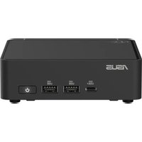
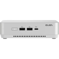


- ASUS NUC 14 PRO/PRO+ KIT/BOARD/MINI-PC
- TECHNICAL PRODUCT SPECIFICATION
- REVISION HISTORY
- DISCLAIMER
- LIMITATION OF LIABILITY
- SERVICE AND SUPPORT
- PREFACE
- INTENDED AUDIENCE
- WHAT THIS DOCUMENT CONTAINS
- TYPOGRAPHICAL CONVENTIONS
- NOTES, CAUTIONS, AND WARNINGS
- NOTE
- CAUTION
- PRODUCTION IDENTIFICATION INFORMATION
- SPECIFICATION CHANGES OR CLARIFICATIONS
- ERRATA
- ONLINE SUPPORT
- TO FIND INFORMATION ABOUT
- VISIT THIS WORLD WIDE WEB SITE
- TABLE OF CONTENTS
- PRODUCT DESCRIPTION
- PRODUCT LAYOUT
- FEATURE DESCRIPTIONS
- TECHNICAL REFERENCE
- OVERVIEW OF BIOS FEATURES
- LIST OF FIGURES
- LIST OF TABLES
- OVERVIEW
- SUMMARY OF MINI PC SKUS
- SUMMARY OF STANDARD KIT AND BOARD SKUS
- FEATURE SUMMARY KITS
- BOARD LAYOUT
- BOARD LAYOUT (BOTTOM)
- BOARD LAYOUT (TOP)
- FRONT PANEL
- BACK PANEL
- CHASSIS EXPANDABILITY OPTIONS
- BLOCK DIAGRAM
- GRAPHICS SUBSYSTEM
- INTEL® ARC™ GRAPHICS
- NOTES
- INTEL® GRAPHICS FOR
- TH GEN INTEL PROCESSORS
- DISPLAY EMULATION
- SATA INTERFACE
- REAL-TIME CLOCK SUBSYSTEM
- LAN SUBSYSTEM
- RJ-45 LAN CONNECTOR WITH INTEGRATED LEDS
- HARDWARE MANAGEMENT SUBSYSTEM
- FAN MONITORING
- SYSTEM STATES AND POWER STATES
- WAKE-UP DEVICES AND EVENTS
- CONNECTORS AND HEADERS
- SIGNAL TABLES FOR THE CONNECTORS AND HEADERS
- FRONT PANEL HEADER (2.0 MM PITCH)
- HARD DRIVE ACTIVITY LED HEADER
- POWER/SLEEP LED HEADER
- POWER SWITCH HEADER
- BIOS SECURITY JUMPER
- INTEL® MANAGEMENT ENGINE BIOS EXTENSION (INTEL® MEBX) RESET HEADER
- FAN HEADER CURRENT CAPABILITY
- POWER SUPPLY CONNECTORS
- MECHANICAL CONSIDERATIONS
- NUC 14 PRO CHASSIS IMAGES
- NUC 14 PRO+ CHASSIS IMAGES
- FORM FACTOR
- THERMAL CONSIDERATIONS
- RELIABILITY
- ENVIRONMENTAL
- INTRODUCTION
- BIOS UPDATES
- BIOS RECOVERY
- BOOT OPTIONS
- BOOT DEVICE SELECTION DURING POST
- POWER BUTTON MENU
- HARD DISK DRIVE PASSWORD SECURITY FEATURE
- ENTER HARD DISK DRIVE PASSWORD
- HARD DISK DRIVE PASSWORD ENTRY ERROR
- BIOS SECURITY FEATURES
- BIOS ERROR MESSAGES
Brand : ASUS
Model : NUC 14 Pro Kit
Category : Mini PC