
HSU-12HEK03-R2 - Air-conditioner HAIER - Free user manual and instructions
Find the device manual for free HSU-12HEK03-R2 HAIER in PDF.
| Product Type | Wall-mounted air conditioner |
| Brand | HAIER |
| Model | HSU-12HEK03-R2 |
| Installation Type | Fixed (wall-mounted) |
| Power Supply | 220-240 V ~ 50 Hz (estimated) |
| Cooling Capacity | 12000 BTU/h |
| Heating Capacity | 12000 BTU/h (heat pump) |
| Liquid Connection | 6.35 mm (1/4") |
| Gas Connection | 9.52 mm (3/8") |
| Max Piping Length | 10 m |
| Max Elevation Difference | 5 m |
| Provided Accessories | Remote control, batteries, mounting plate, drain hose, connection cable, cushions, etc. |
| Main Functions | Cooling, heating, dehumidification, ventilation |
| Filter Cleaning | Recommended every 15 days |
| Safety | Residual current circuit breaker recommended, mandatory grounding |
| Repairability | Spare parts available from the manufacturer |
Frequently Asked Questions - HSU-12HEK03-R2 HAIER
User questions about HSU-12HEK03-R2 HAIER
0 question about this device. Answer the ones you know or ask your own.
Ask a new question about this device
Download the instructions for your Air-conditioner in PDF format for free! Find your manual HSU-12HEK03-R2 - HAIER and take your electronic device back in hand. On this page are published all the documents necessary for the use of your device. HSU-12HEK03-R2 by HAIER.
USER MANUAL HSU-12HEK03-R2 HAIER
Necessary Tools for Installation
1.Driver
2.Hacksaw
3.Hole core drill
4SPANer(17,19 and 26mm)
5.Torque wrench(17mm,22mm,26mm)
6.Pipe cutter
7.Flaring tool
8.Knife
9.Nipper
- Gas leakage detector or soap-and-water solution
11.Measuring tape
12.Reamer
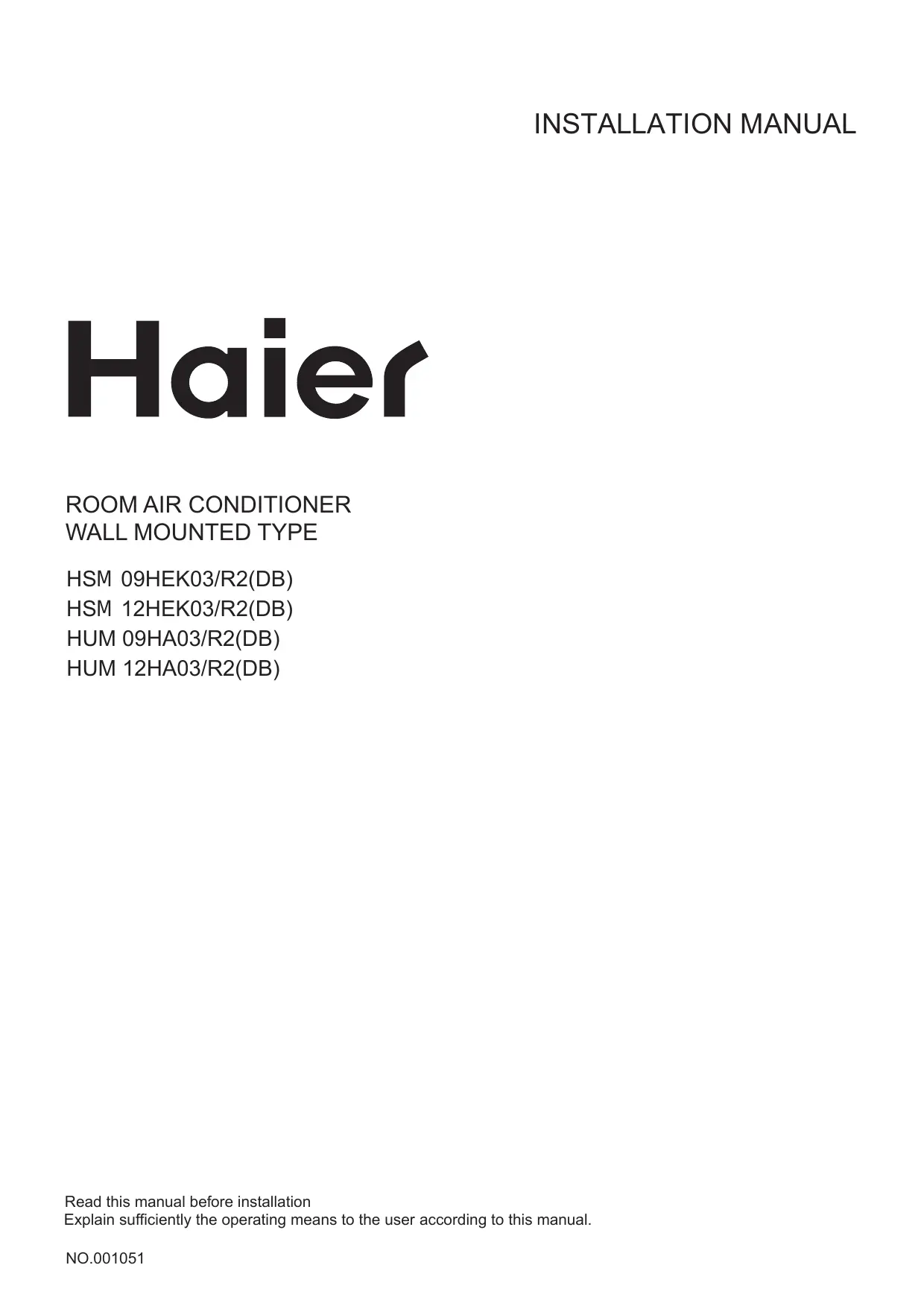
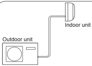
Drawing for the installation of indoor and outdoor units
Accessory parts
| No. | Accessory parts | Number of articles |
| ① | Remote controller | 1 |
| ② | R-03 dry battery | 2 |
| ③ | Mounting plate | 1 |
| ④ | Drain hose | 1 |
| ⑤ | Φ4X50 Steel nail, cement | 6 |
| ⑥ | Φ4X25 Screw Plastic cap | 4 |
| ⑦ | Drain-elbow | 1 |
| ⑧ | Cover | 1 |
| ⑨ | Cushion | 4 |
| ⑩ | Pipe supporting plate | 1 |
| ⑪ | Connecting cable | 1 |
Optional parts for piping
| Mark | Parts name |
| A | Non-adhesive tape |
| B | Adhesive tape |
| C | Saddle(L.S) with screws |
| D | Connecting electric cable for indoor and outdoor |
| E | Drain hose |
| F | Heating insulating material |
| G | Piping hole cover |
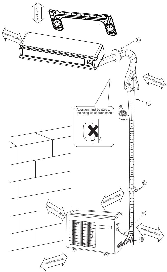
Floor fixing dimensions of the outdoor unit (Unit:mm)
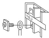
Fixing of outdoor unit
Fix the unit to concrete or block with bolts ( 10mm) and nuts firmly and horizontally.
- When fitting the unit to wall surface, roof or rooftop, fix a supporter surely with nails or wires in consideration of earthquake and strong wind.
- If vibration may affect the house, fix the unit by attaching a vibration-proof mat.
Indoor Unit
Selection of Installation Place
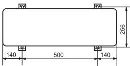
Outdoor Unit
- Place, robust not causing vibration, where the body can be supported sufficiently.
- Place, not affected by heat or steam generated in the vicinity, where inlet and outlet of the unit are not disturbed.
- Place, possible to drain easily, where piping can be connected with the outdoor unit.
- Place, where cold air can be spread in a room entirely.
- Place, nearby a power receptacle, with enough space around. (Refer to drawings).
- Place where the distance of more than 1m from televisions, radios, wireless apparatuses and fluorescent lamps can be left.
-
In the case of fixing the remote controller on a wall, place where the indoor unit can receive signals when the fluorescent lamps in the room are lightened.
-
Place, which is less affected by rain or direct sunlight and is sufficiently ventilated.
- Place, possible to bear the unit, where vibration and noise are not increased.
- Place, where discharged wind and noise do not cause a nuisance to the neighbors.
- Place, where a distance marked is available as illustrated in the above figure.
Power Source
Before inserting power plug into receptacle, check the voltage without fail. The power source is the same as the corresponding name plate.
Install an exclusive branch circuit of the power.
A receptacle shall be set up in a distance where the power cable can be reached. Do not extend the cable by cutting it.
Selection of pipe
- To this unit, both liquid and gas pipes shall be insulated as they become low temperature in operation.
- Use optional parts for piping set or pipes covered with equivalent insulation material.
| For 09 | For 12 | |
| Liquid pipe (∅) | 6.35mm(1/4") | 6.35mm(1/4") |
| Gas pipe (∅) | 9.52mm(3/8") | 9.52mm(3/8") |
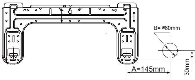
1. Fitting of the Mounting Plate and Positioning of the wall Hole
When the mounting plate is first fixed
- Carry out, based on the neighboring pillars or lintels, a proper leveling for the plate to be fixed against the wall, then temporarily fasten the plate with one steel nail.
- Make sure once more the proper level of the plate, by hanging a thread with a weight from the central top of the plate, then fasten securely the plate with the attachment steel nail.
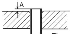
- Find the wall hole location A using a measuring tape
When the mounting plate is fixed side bar and lintel
Fix to side bar and lintel a mounting bar, Which is separately sold, and then fasten the plate to the fixed mounting bar.
Refer to the previous article, " When the mounting plate is first fixed", for the position of wall hole.
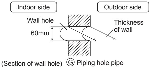
2. Making a Hole on the Wall and Fitting the Piping Hole Cover
Make a hole of 60~mm in diameter, slightly descending to outside the wall.
- Install piping hole cover and seal it off with putty after installation
3.Installation of the Indoor Unit
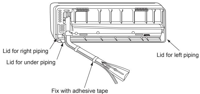
Drawing of pipe
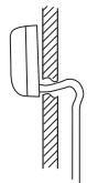
[ Rear piping ]
- Draw pipes and the drain hose, then fasten them with the adhesive tape
[Left • Left-rear piping]
- In case of left side piping, cut away, with a nipper, the lid for left piping.
- In case of left-rear piping, bend the pipes according to the piping direction to the mark of hole for left-rear piping which is marked on heat insulation materials.
Indoor unit
- Insert the drain hose into the dent of heat insulation materials of indoor unit.
- Insert the indoor/outdoor electric cable from backside of indoor unit, and pull it out on the front side, then connect them.
- Coat the flaring seal face with refrigerant oil and connect pipes.
Cover the connection part with heat insulation materials closely, and make sure fixing with adhesive tape
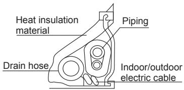
- Indoor/outdoor electric cable and drain hose must be bound with refrigerant piping by protecting tape.
[Other direction piping]
- Cut away, with a nipper, the lid for piping according to the piping direction and then bend the pipe according to the position of wall hole. When bending, be careful not to crash pipes.
- Connect beforehand the indoor/outdoor electric cable, and then pull out the connected to the heat insulation of connecting part specially.
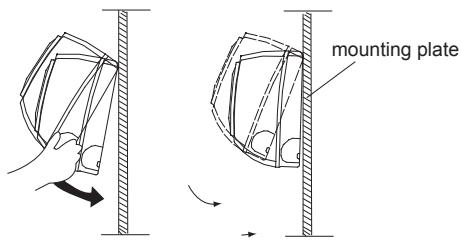
Fixing the indoor unit body
- Hang surely the unit body onto the upper notches of the mounting plate. Move the body from side to side to verify its secure fixing.
- In order to fix the body onto the mounting plate, hold up the body aslant from the underside and then put it down perpendicularly.
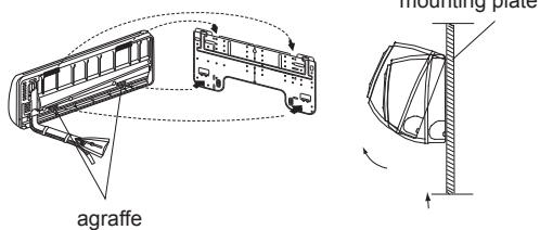
Unloading of indoor unit body
- When you unload the indoor unit, please use your hand to arise the body to leave agraffe, then lift the bottom of the body outward slightly and lift the unit aslant until it leaves the mounting plate.
Indoor unit
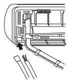
Connecting the indoor/outdoor Electric Cable
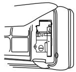
Removing the wiring cover
- Remove terminal cover at right bottom corner of indoor unit, then take off wiring cover by removing its screws.
When connecting the cable after installing the indoor unit
- Insert from outside the room cable into left side of the wall hole, in which the pipe has already existed.
- Pull out the cable on the front side, and connect the cable making a loop.
When connecting the cable before installing the indoor unit
- Insert the cable from the back side of the unit, then pull it out on the front side.
- Loosen the screws and insert the cable ends fully into terminal block, then tighten the screws.
- Pull the cable slightly to make sure the cables have been properly inserted and tightened.
- After the cable connection, never fail to fasten the connected cable with the wiring cover.
Note: When connecting the cable, confirm the terminal number of indoor and outdoor units carefully. If wiring is not correct, proper operation can not be carried out and will cause defect.
- If the supply cord is damaged, it must be replaced by the manufacturer or its service agent or a similar qualified person. The type of connecting wire is H05/07RN-F or 245IEC57(YZW).
- If the fuse on PC board is broken please change it with the type of T. 3.15A/250V.
- The wiring method should be in line with the local wiring standard.
- After installation, the power plug should be easily reached.
- A breaker should be incorporated into fixed wiring. The breaker should be all-pole switch and the distance between its two contacts should be not less than 3mm .
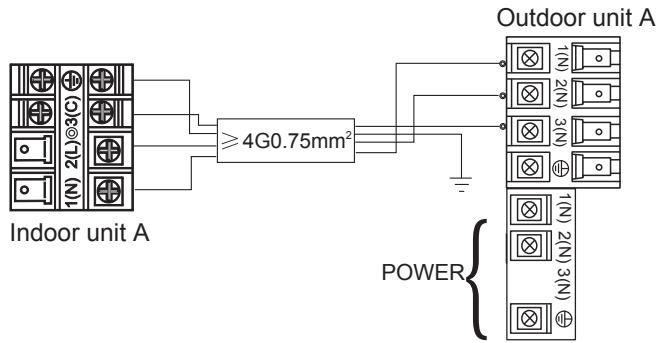
Power cable: ≥slant 3G1.5mm^2
Outdoor unit
1.Installation of Outdoor Unit
Install according to (Drawing for the installation of indoor and outdoor units
2.Connection of pipes
- To bend a pipe, give the roundness as large as possible not to crush the pipe
- Connecting the pipe of gas side first makes working easier.
- The max vertical distance between the indoor unit and the outdoor unit is 5m .
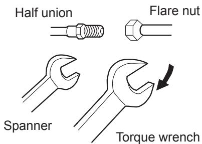
| Forced fastening without careful centering may damage the threads and cause a leakage of gas. |
| Pipe Diameter (Φ) | Fastening torque |
| Liquid side 6.35mm(1/4") | 18N.m |
| Gas side 9.52mm(3/8") | 42N.m |
Be careful that matters, such as wastes of sands, etc. shall not enter the pipe.
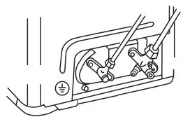
3.Connection
- Use the same method on indoor unit. Loosen the screws on terminal block and insert the plugs fully into terminal block, then tighten the screws.
- Insert the cable according to terminal number in the same manner as the indoor unit.
- If wiring is not correct, proper operation can not be carried out and controller may be damaged.
Fix the cable with a clamp.
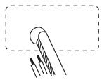
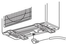
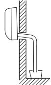
4. Attaching Drain-Elbow
- If the drain-elbow is used, please attach it as figure. (Note: Only for heat pump unit.)
Outdoor unit
5.Purging Method:
Push the air out of the indoor unit and piping as follows:
(1) Remove the valve cap on 2-way valve in outdoor unit.
(2) Loosen by 1/2 turn the flare nut of gas pipe, which is is conneted to 3-way valve.
(3) Loosen 2-way valve by 90^ using hexagon wrench, and after approx.10 sec tighten it up. Gas comes out through flare nut on wide pipe. If no gas is discharged, tighten flare nut with specified torque.
(4) Open 2-way and 3-way valves using specified torque.
(5) Tighten the caps on the valves with specified torque.
| Tighten torque N.m | |
| Valve rod | 7-9 |
| Valve cap | 20-25 |
- When connecting pipe exceeds 5 meters, 20g refrigerant shall be added per exceeding meter. Charge according to the following list.
| for 9k 12k | |||
| Piping length | 5m | 7m | 10m |
| Additional amount | No need | 40g | 100g |
2-way valve 3-way valve 6.35mm(1 / 4^ ) 9.52mm(3/8")
Max.Elevation:5m
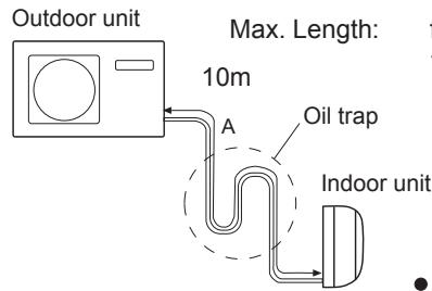
for 9K : A=7m
for 12K : A=10m
CAUTION In case more than 5m Oil trap should be installed every 5 7m
- no more gas if the length of connecting pipe is less than 7m(9K) or 10m(12K) .
-
The height difference between any two indoor or outdoor units can not be more than 5m .
-
Note: When extending piping, air inside piping shall be removed by using external refrigerant gas, charge according to the following list.
Brand new outdoor unit is charged 50g more refrigerant than regulated weight. Only for first installation, this extra 50g can be used to purge air in pipes.
1 During this procedure, 50g refrigerant will be discharged in piping.
(This must be strictly controlled within 90^ and 10 sec.)
1.Power Source Installation
- The power source must be exclusively used for air conditioner. (Over 10A)
- In the case of installing an air conditioner in a moist place, please install an earth leakage breaker.
- For installation in other places, use a circuit breaker as far as possible.
2.Cutting and Flaring Work of Piping
- Pipe cutting is carried out with a pipe cutter and burs must be removed.
After inserting the flare nut, flaring work is carried out.
Flare tooling die
| Pipe diameter(φ) | Size A(mm) | |
| Liquid side | 6.35mm(1/4") | 0.8~1.5 |
| Gas side | 9.52mm(3/8") | 1.0~1.8 |
| Gas side | 12.7mm(1/2") | 1.2~2.0 |
| Correct | Incorrect |
| Lean Damage of flare Crack Partial Too outside |
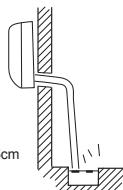
3. On Drainage
Please install the drain hose so as to be downward slope without fail. Please don't do the drainage as shown below.
It becomes high midway.
The end is immersed in water.
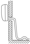
It waves.
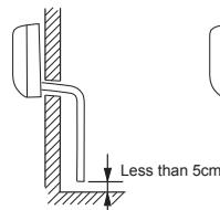
The gap with the ground is too small
There is the bad smell from a ditch
- Please pour water in the drain pan of the indoor unit, and confirm that drainage is carried out surely to outdoor.
- In case that the attached drain hose is in a room, please apply heat insulation to it without fail.
Check for Installation and Test Run
- Please kindly explain to our customers how to operate through the instruction manual.
Check Items for Test Run
Put check mark in boxes
Gas leak from pipe connecting?
Heat insulation of pipe connecting
Are the connecting wirings of indoor and outdoor firmly inserted to the terminal block?
Is the connecting wiring of indoor and outdoor firmly fixed?
Is drainage securely carried out?
Is the earth line securely connected?
□ Is the indoor unit securely fixed?
□ Is power source voltage abided by the code?
□ Is there any noise?
□ Is the lamp normally lighting?
Are cooling and heating (when in heat pump) performed normally?
Is the operation of room temperature regulator normal?