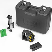
LAX 500 G - Laser level Stabila - Free user manual and instructions
Find the device manual for free LAX 500 G Stabila in PDF.


| Product Type | Laser Level (Cross-Line) |
| Model | LAX 500 G |
| Brand | Stabila |
| Dimensions (approx.) | 100 x 80 x 60 mm |
| Weight (with batteries) | 0.4 kg |
| Power Supply | 2 x AA batteries (1.5V) |
| Laser Class | Class 2 (<1 mW @ 635 nm) |
| Self-Leveling Range | ±4° |
| Accuracy | ±0.3 mm/m |
| Working Range (diameter) | Up to 20 m (with detector) |
| Laser Lines | 1 horizontal, 1 vertical |
| Protection Class | IP54 (dust and splash water) |
| Operating Temperature | -10°C to 50°C |
| Storage Temperature | -20°C to 60°C |
| Key Features | Self-leveling; lock for transport; threaded insert for tripod |
| Maintenance | Clean housing with dry, soft cloth; keep lenses clean |
| Safety | Avoid direct eye exposure; do not open housing |
| Spare Parts & Repairability | Spare parts not available; professional repair only |
| General Notes | Always read user manual before use |
Frequently Asked Questions - LAX 500 G Stabila
User questions about LAX 500 G Stabila
0 question about this device. Answer the ones you know or ask your own.
Ask a new question about this device
Download the instructions for your Laser level in PDF format for free! Find your manual LAX 500 G - Stabila and take your electronic device back in hand. On this page are published all the documents necessary for the use of your device. LAX 500 G by Stabila.
USER MANUAL LAX 500 G Stabila
How true pro's measure
GREEN BEAM
LAX 500 G
Operating instructions

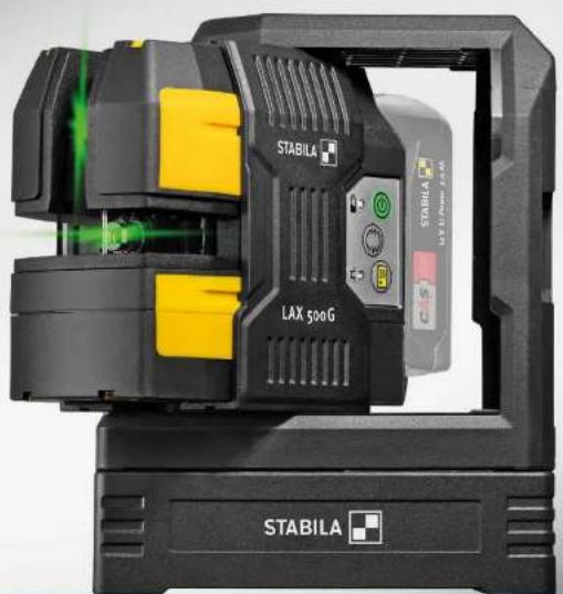
LAX 500 G
en
Contents
Section
Page
• 1. Intended use 3
• 2.1 Safety instructions for laser units 3
• 2.2 Safety instructions for the Li-ion battery pack 3
• 3. Components of the unit 4
• 4. Commissioning 5
• 4.0 Inserting, removing and charging the battery 5
- 4.1 Unlocking and setting up 6
• 4.2 Switching the unit on 7
■ 4.3 Commissioning without the levelling function 7
- 5. Functions 8
• 5.1 Selecting laser functions 8
- 5.2 Working with the receiver 8
- 6. LED indicators 9
• 7.1 Using the laser with the SLB 500 laser base 10
- 7.2 Using the SWB10 bracket 10
• 8. Checking accuracy 11
• 8.1 Vertical check 11
• 8.2 Checking the plumb-line function 11
- 8.2 Horizontal check 12
• 9. Technical data 13
LAX 500 G
1. Intended use
Congratulations on the purchase of your STABILA measuring tool.
The STABILA LAX 500 G is an easy-to-use cross line and plumb-line laser for horizontal and vertical levelling. Plumb-line dots enable you to align and create plumb lines on structural elements. It is self-levelling within a range of ± 5° .
The laser lines are pulsed, which makes it possible to work over greater distances using a special STABILA line receiver. Receivers must be suitable for green laser beams.
For more information refer to the operating instructions for the line receiver.
The LAX 500 G can only be operated with a 12V Li-ion CAS system battery.
Their green colour also ensures that you can see them perfectly, even in bright lighting conditions.

If you still have questions after reading the operating instructions, you can obtain advice over the phone at any time:

+49 / 63 46 / 3 09 - 0
Equipment and functions:
- Pulsed laser lines
- 1x vertical laser line
• 1x horizontal laser line - 90° angle in horizontal direction
- Plumb line laser function
- Manual mode
- Attached with rare-earth magnets
- 1/4" tripod socket
- SLB 500 laser base
- SWB10 wall bracket
- Target plate
- Carrying case
- STABILA CAS – 12 V Li-Power 2.0 Ah battery – not included in every set
- SC 30 charger, 12-18 V, CAS system – not included in every set
en
2.1 Safety instructions for laser units

LASER
2

IEC 60825-1:2014

In Class 2 laser units, your eyes are usually protected from accidental, short-term exposure to the laser beam by the eyelid-closing reflex and/or the reflex reaction to turn one's head. If a laser beam hits your eye, deliberately close your eyes and move your head out of the path of the beam. Do not look into the direct or reflected beam.
The STABILA laser goggles available for our laser units are not safety eyewear: their function is to improve the visibility of the laser beam.
- Do not aim the laser beam directly at people!
- Avoid dazzling other people with the unit!
- Keep the unit out of the reach of children!
- If operating or adjustment equipment that has not been specified here is used, or if the unit is not operated in the ways described here, this may result in hazardous exposure to radiation!
2.2 Safety instructions for the Li-ion battery pack
Thoroughly read the safety instructions and operating instructions for the Li-ion battery pack.

3. Components of the unit
- Protective frame: with magnet and tripod socket
- Exit window: Horizontal and vertical laser line, plumb-line dot upwards
- Exit window: Plumb-line dot downwards
- Protective slider: Mechanical lock
- Magnet surface
- Contact edge: Makes aligning with plumb-line dot easier
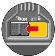
- Sliding switch: ON/OFF, mechanical lock
- Button: Manual mode, ON/OFF
- Button: Laser lines
- Button: Pulse mode for receiver operation
- Green/red LED: Operating status ON/OFF, battery
- Green LED: Pulse mode, operating temperature
- Housing:
- Protected against water jets and dust in accordance with IP 54 14.1/4" tripod socket
- Serial number
- Rechargeable battery
- SLB 500 laser base
- SWB10 wall bracket
- Hanging hole
- Clamp
- Sliding switch
- Fine adjustment
- Locking screw for height adjustment
- Adjusting screw to align the bracket


12 V Li-Power 2.0 Ah
12 V Li-Power 4.0 Ah (optional)

4. Commissioning
4.0 Inserting, removing and charging the battery
Only 12 V Li-ion CAS System (Cordless Alliance System) battery packs can be used.
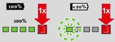
Push in the battery pack in the direction of the arrow up to the stop. The battery pack must have an adequate charge capacity. Fully charge the battery pack before initial commissioning (observe the display). Do not recharge a fully charged battery pack. To remove the battery, pull it upwards from the sliding seat.
Check the charge capacity: Press the red button.
The battery pack must not be inserted in the charger.
LED display:
low charge capacity ( <20% ) – charge the battery pack
Do not allow the battery pack to become fully discharged.
Charging the battery pack:
Read the safety instructions and operating instructions for the battery pack through carefully.
Remove the battery pack from the laser unit.
Insert the battery pack into the charger.
Connect the charger to the mains plug.
Once the charging process has finished, the charger automatically switches to conservation mode.
The battery pack can remain in the charger.
LAX 500 G
en
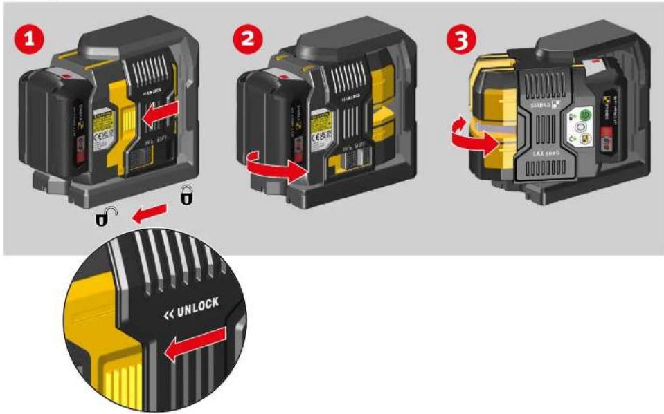
4.1 Unlocking and setting up
When the protective slider is slid on, the laser exit windows are enabled. At the same time, the laser unit is unlocked and can be turned in the desired direction.
LAX 500 G

en




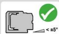
The laser beam flashes if the inclination of the laser unit is too steep. The laser unit is outside the self-levelling range and cannot level itself automatically.

4.2 Switching the unit on
Move the laser unit to the working position and switch on using the sliding switch.
The LAX 500 G always starts in horizontal mode and levels itself automatically. Now select the laser functions ( → 5.1).
The green LED indicates that the unit is switched on.

Always use the centre of the laser line when marking and aligning.


7
4.3 Commissioning without the levelling function
Marking function mode can only be switched on with the "Manual mode" button. For this purpose, press and hold it for more than 2 seconds.
The laser beam flashes 2 x every 5 seconds. The LAX 500 G is not in self-levelling function mode and can only be used in this mode for marking and alignment!
LAX 500 G
en


5. Functions
5.1 Selecting laser functions
Once the unit has been switched on, the "Laser lines" button can be used to set the various laser functions.
Plumb-line function
Transfers a determined point from the floor to the ceiling.
5.2 Working with the receiver
Pulse mode must be activated for work completed over larger distances or using a suitable receiver.
Note:
The receiver must be suitable for both pulsed and green laser lines.
LAX 500 G
6. LED indicators

Operation with levelling function

Operation without levelling function

Operation with levelling function Battery capacity low

Operation with levelling function Laser in pulse mode

Operation activated Battery temperature ≤ -20°C / -4°F Ensure the unit is in the operating temperature range Check accuracy
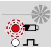
Operation activated Battery temperature >70°C / 158°F Ensure the unit is in the operating temperature range Check accuracy
en

Operation activated Unit temperature > 60°C / 140°F Ensure the unit is in the operating temperature range
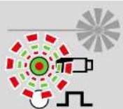
Operation activated Battery check failed Replace the battery pack

Operation activated Get in touch with STABILA

CAS battery charge capacity too low --> Insert battery pack and charge

LED/laser beam lights up constantly
LED/laser beam flashes
LED flashes and changes colour
LAX 500 G

en
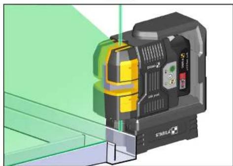
7.1 Using the laser with the SLB 500 laser base
For accurate positioning, the LAX 500 G can be positioned at interior construction profiles using the SLB 500 laser base. As a result, the plumb-line laser is accurately aligned with the component edge.
Use the laser base's profile rails to insert the laser base into the protective frame up to the stop.
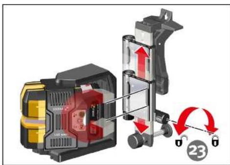


7.2 Using the SWB10 bracket
The LAX 500 G can be attached to and aligned with walls or profiles using the SWB 10 bracket. The clamp can be used to attach the bracket to interior construction profiles. The hanging hole enables it to be hung on nails or hooks.
The bracket must be roughly aligned vertically using the adjusting screw (24), so that the LAX 500 G is in the self-levelling range.
After having released the locking screw for height adjustment (23) the height of the LAX 500 G can be adjusted within a range of 11 mm / 0.4". The exact height is set using the fine adjustment (22).
10
LAX 500 G
en


11
8. Checking accuracy
The LAX 500 G is designed for use on building sites and is perfectly adjusted before leaving our premises. As with all precision instruments, check the calibration accuracy of the unit on a regular basis. Always check the unit before you start work, especially if it has been exposed to heavy vibrations.
Vertical check
Horizontal check
8.1 Vertical check
Checking vertical laser lines
- Create a reference line, e.g. with a plumb line.
- Set up and align the LAX 500 G at a distance of Y in front of this reference line.
- Compare the laser line with the reference line.
- At a distance of 2 m / 7', the laser line must not deviate from the reference line by more than 1 mm / 11/256"
8.2 Checking the plumb-line function
- Align the LAX 500 G precisely with one floor marking using the plumb-line dot.
- Draw plumb-line dot 1 upwards on the room ceiling.
- Turn the LAX 500G by 180° and re-align it with the floor marking using the plumb-line dot.
- Draw plumb-line dot 2 upwards on the room ceiling.
- The difference measured between the markings is twice the actual discrepancy. With a ceiling height of 5 m (16'5"), the difference must be no more than 3 mm (1/8").
LAX 500 G
en



8.2 Horizontal check
Checking line levelling of the horizontal laser line
2 parallel walls at a distance S of at least 5 m (16'5") apart are required to carry out the horizontal check.
- Position the LAX 500 G as closely as possible to wall A on a horizontal surface.
- Using an exit window for a vertical laser line, align the LAX 500 G with wall A.
- Switch on the laser unit.
- Once automatic levelling has ended, mark the cross projected onto wall A. Point 1.
- Turn the LAX 500 G by 180° and align with wall B using the same vertical laser line exit window. Do not adjust the height.
- Once automatic levelling has ended, mark the cross projected onto wall B. Point 2.
- Now reposition the laser unit so that it is directly in front of wall B. Align the LAX 500 G with wall B using the same vertical laser line exit window.
- Move the laser line cross by turning and adjusting the height until it precisely coincides with point 2.
- Turn the LAX 500 G by 180° and align with wall A using the same vertical laser line exit window. Do not adjust the height.
- Move the laser line cross by turning the casing until it precisely coincides with the marking line of point 1.
- Once automatic levelling has ended, mark the cross projected onto wall A. Point 3.
- Measure the vertical distance between points 1 and 3.
Distance S to the wall Maximum permissible distance:
| 5 m | 3.0 mm |
| 10 m | 6.0 mm |
| 15 m | 9.0 mm |
| 16'5" 1/8" | |
| 32'10" 1/4" | |
| 49'3" 3/8" |
12
LAX 500 G
en
9. Technical data
Laser type: Green diode laser, 510–530 nm wavelength
Power output: <1 mW, laser class 2, in accordance with IEC 60825-1:2014
EN60825-1:2014/A11:2021
Self-levelling range: approx. ±5°
Levelling accuracy*:
Laser line: ±0.3 mm/m ± 3/16" over 50ft centre of laser line
Batteries: 12 V 2 Ah Li-ion CAS battery pack
12 V 4 Ah Li-ion CAS battery pack
Battery life: ≤ 20 h
Operating temperature range: -10°C to +50°C / 14°F to 122°F
Storage temperature range: -25°C to +70 °C /-13°F to 158°F
Subject to technical modifications.
* When operated within the specified operating temperature range
2025
STABILA Messgeräte
Gustav Ullrich GmbH
Landauer Str. 45
76855 Annweiler
Germany


- LAX 500 G
- EN
- CONTENTS
- SECTION
- PAGE
- INTENDED USE
- EQUIPMENT AND FUNCTIONS
- 2.1 SAFETY INSTRUCTIONS FOR LASER UNITS
- 2.2 SAFETY INSTRUCTIONS FOR THE LI-ION BATTERY PACK
- COMPONENTS OF THE UNIT
- COMMISSIONING
- 4.0 INSERTING, REMOVING AND CHARGING THE BATTERY
- CHARGING THE BATTERY PACK
- 4.1 UNLOCKING AND SETTING UP
- 4.2 SWITCHING THE UNIT ON
- 4.3 COMMISSIONING WITHOUT THE LEVELLING FUNCTION
- FUNCTIONS
- 5.1 SELECTING LASER FUNCTIONS
- PLUMB-LINE FUNCTION
- 5.2 WORKING WITH THE RECEIVER
- LED INDICATORS
- 7.1 USING THE LASER WITH THE SLB 500 LASER BASE
- 7.2 USING THE SWB10 BRACKET
- CHECKING ACCURACY
- 8.1 VERTICAL CHECK
- CHECKING VERTICAL LASER LINES
- 8.2 CHECKING THE PLUMB-LINE FUNCTION
- 8.2 HORIZONTAL CHECK
- CHECKING LINE LEVELLING OF THE HORIZONTAL LASER LINE
- TECHNICAL DATA
Brand : Stabila
Model : LAX 500 G
Category : Laser level