
450 XC-F - Off-road motorcycle KTM - Free user manual and instructions
Find the device manual for free 450 XC-F KTM in PDF.


| Product type | Off-road motorcycle |
| Brand | KTM |
| Model | 450 XC-F |
| Engine | Single-cylinder 4-stroke, 449.3 cc |
| Bore x stroke | 97 mm x 60.8 mm |
| Compression ratio | 12.5:1 |
| Cooling | Water, forced circulation |
| Transmission | 5 gears + reverse |
| Clutch | Hydraulic, self-adjusting |
| Frame | Chrome-molybdenum steel central tube |
| Front suspension | WP 4860 MXMA CC fork, travel 300 mm |
| Rear suspension | WP PDS 5018 DCC shock, travel 335 mm |
| Front brakes | Disc 260 mm, floating caliper |
| Rear brakes | Disc 220 mm, floating caliper |
| Front tire | 80/100-21 51 M TT Bridgestone M59 |
| Rear tire | 110/100-18 64 M TT Bridgestone M402 |
| Steering head angle | 63.5° |
| Wheelbase | 1465-1485 mm |
| Seat height (loaded) | 925 mm |
| Ground clearance (loaded) | 380 mm |
| Weight without fuel | 108.3 kg |
| Fuel tank capacity | 9.2 L (unleaded premium) |
| Engine oil capacity | 1.35 L (SAE 10W/50) |
| Coolant capacity | 1.2 L |
| Battery | 12 V, 4 Ah (YTX5L-BS) |
Frequently Asked Questions - 450 XC-F KTM
User questions about 450 XC-F KTM
0 question about this device. Answer the ones you know or ask your own.
Ask a new question about this device
Download the instructions for your Off-road motorcycle in PDF format for free! Find your manual 450 XC-F - KTM and take your electronic device back in hand. On this page are published all the documents necessary for the use of your device. 450 XC-F by KTM.
USER MANUAL 450 XC-F KTM
Congratulations on your decision to buy a KTM motorcycle. You are now the owner of a state-of-the-art sports motorcycle that will give you enormous pleasure if you service and maintain it accordingly.
We wish you great pleasure riding the vehicle!
Enter the serial numbers of your vehicle below.
| Chassis number (7) | Dealer's stamp |
| Engine number (7) |
The owner's manual corresponded to the latest state of this series at the time of printing. Slight deviations resulting from continuing development and design of our motorcycles can however not be completely excluded. The owner's manual is an important component of the motorcycle and should be handed over to the new owner if the vehicle is sold.
All specifications are not binding. KTM Sportmotorcycle AG in particular reserves the right to modify or delete technical specifications, prices, colors, forms, materials, services, designs, equipment, etc., without prior notice and without specifying reasons, to adapt these to local conditions, as well as to stop prudction of a particular model without prior notice. KTM accepts no liability for delivery options, deviations from illustrations and descriptions, as well as printing and other errors. The models portrayed partly contain special equipment that does not belong to the regular scope of delivery.
© 2007 by KTM-Sportmotorcycle AG, Mattighofen Austria
All rights reserved
Reproduction, even in part, is permitted only with the express written permission of the copyright owner.

ISO 9001(12 100 6061)
Within the meaning of the international quality management standard ISO 9001, KTM uses quality assurance processes that lead to the maximum possible quality of the products.
REG.NO.12 100 6061
Issued by: TÜV Management Service
KTM-Sportmotorcycle AG
5230 Mattighofen, Austria
MEANS OF REPRESENTATION 4
IMPORTANT NOTES 5
LOCATION OF SERIAL NUMBERS 7
Chassis number. 7
Type label. 7
Engine number. 7
Fork part number. 7
Shock absorber part number 7
OPERATING ELEMENTS 8
Clutch lever 8
Hot start lever 8
Hand brake lever 8
Short circuit button 8
Electric starter button 8
Fuel tap (450 SX-F, 505 SX-F) 9
Fuel tap (450 XC-F, 505 XC-F) 9
Opening filler cap. 9
Closingfillercap 10
Choke. 10
Shift lever. 10
Foot brake pedal 11
Plug-in stand (450 SX-F, 505 SX-F) 11
Side stand (450 XC-F, 505 XC-F) 11
TIPS AND HINTS ON PUTTING INTO OPERATION 12
Advice on first use 12
Running in the engine 13
RIDINGINSTRUCTIONS 14
Checks before putting into operation 14
Starting 14
Starting up 15
Shifting, riding. 15
Braking 15
Stopping, parking. 16
Refueling. 16
GREASING AND SERVICE TABLE 17
Important maintenance work to be carried out by an authorized KTM workshop. 17
Important maintenance work to be carried out by an authorized KTM workshop. (as additional order). 18
Important checks and maintenance work to be carried out by the rider. 18
MAINTENANCE WORK ON CHASSIS AND ENGINE 20
Jacking up the motorcycle 20
Removing the motorcycle from the work stand 20
Checking the basic chassis setting with the rider's weight 20
Compression damping of shock absorber 20
Adjusting high-speed compression damping of the shock absorber 20
Adjusting the low-speed compression damping of the shock absorber 21
Adjusting rebound damping of the shock absorber 21
Measuring rear wheel sag unloaded 22
Checking static sag of the shock absorber 22
Check the riding sag of the shock absorber. 23
Adjusting spring preload of the shock absorber 23
Adjusting riding sag 24
Removing the shock absorber 24
Installing shock absorber 24
Checking basic setting of fork 25
Adjusting compression damping of fork 25
Adjusting rebound damping of fork 25
Bleeding fork legs. 26
Cleaning dust boots of fork legs 26
Loosening the fork protection 26
Positioning the fork protection 27
Checking play of steering head bearing 27
Adjusting play of steering head bearing 27
Fork offset 28
Setting the fork offset 28
Removing the fork legs 28
Installing the fork legs 29
Removing the fork protector 29
Installing the fork protector 29
Removing the lower triple clamp 30
Installing the lower triple clamp 30
Greasing the steering head bearing 31
Dismounting the front fender 31
Installing the front fender 31
Dismount the start number plate 31
Fitting the start number plate 32
Handlebar position 32
Adjusting handlebar position 32
Checking gas Bowden cable route 32
Checking play in gas Bowden cable 33
Adjusting play in gas Bowden cable 33
Checking chain dirt 33
Cleaning the chain. 33
Checking the chain tension 34
Checking the chain tension - fitting rear wheel 34
Checking rear sprocket / engine sprocket for wear 35
Checking chain wear 35
Adjusting chain tension 35
Adjusting chain tension - after checking 36
Adjusting chain tension - fitting rear wheel 37
Adjusting chain guide (450 SX-F, 505 SX-F) 37
Adjusting chain guide (450 XC-F, 505 XC-F) 38
Brake fluid reservoir. 38
Brake calipers 38
Checking brake discs 38
Checking free play of hand brake lever. 39
Adjusting basic position of handbrake lever 39
Checking front brake fluid level 39
Topping up the front brake fluid 40
Checking the front brake linings. 40
Removing front brake linings 41
Mounting front brake linings 41
Changing the fron brake linings 42
Checking free play of foot brake lever 42
Adjusting basic position of footbrake lever 43
Checking rear brake fluid level 43
Topping up brake fluid of front brake 44
Checking rear brake linings 44
Removing rear brake linings 45
Mounting rear brake linings 45
Changing rear brake linings 46
Removing front wheel 46
Fitting front wheel 47
Removing rear wheel 48
Fitting rear wheel 48
Tire condition checking 49
Checking tire air pressure 49
Checking spoke tension. 50
Removing the battery 50
Installing the battery 50
Recharging the battery 51
Removing a fuse. 52
Replacing the fuse. 52
Ignition curve 52
Ignition curve plug connection 52
Changing ignition curve. 53
Removing the seat 53
Mounting the seat 53
Dismounting the fuel tank 53
Installing the fuel tank 54
Cooling system 55
Checking antifreeze and coolant level 55
Checking the coolant level. 56
Draining coolant 56
Refilling coolant 57
Removing main silencer 57
Fitting the main silencer 57
Glass fiber yarn filling of main silencer 57
Removing glass fiber yarn filling from the main silencer 58
Fitting glass fiber yarn filling in main silencer 58
Changing glass fiber yarn filling of main silencer 59
Dismounting the air filter box lid 59
Installing the air filter box lid. 59
Removing the air filter 59
Installing the air filter 60
Cleaning air filter 60
Adjusting basic position of clutch lever. 60
Checking fluid level of hydraulic clutch 60
Changing fluid level of hydraulic clutch 61
Carburetor - idle 61
Carburetor - adjusting idle 62
Emptying the carburetor float chamber 63
Checking engine oil level 63
Changing engine oil and oil filter, cleaning oil screen 64
Draining the engine oil 64
Cleaning the oil screen 64
Removing the oil filter 65
Mounting oil filter 65
Filling up with engine oil 66
Topping up engine oil 66
TROUBLESHOOTING 67
CLEANING 69
Cleaning motorcycle 69
Storage. 70
Storage 70
TECHNICAL DATA - ENGINE 71
Capacity- engine oil 72
Capacity- cooling liquid. 72
TECHNICAL DATA - ENGINE TIGHTENING TORQUES 73
TECHNICAL DATA-CARBURETOR. 75
TECHNICAL DATA - CHASSIS 76
Capacity - fuel. 76
TECHNICAL DATA - FORK. 77
CAPACITY-FORK OIL 77
TECHNICAL DATA - SHOCK ABSORBER 78
TECHNICAL DATA - CHASSIS TIGHTENING TORQUES 79
WIRINGDIAGRAM 80
WIRINGDIAGRAM 80
SUBSTANCES 82
AUXILIARY SUBSTANCES. 84
INDEX 86
Symbols used
The symbols used are explained in the following.

Indicates an expected reaction (e.g. of a work step or a function)

Indicates an unexpected reaction (e.g. of a work step or a function)

All work marked with this symbol requires specialist knowledge and technical understanding. In the interest of your own safety, have these jobs done in an authorized KTM workshop! There, your motorcycle will be serviced optimally by specially trained experts using the specialist tools required.

Identifies a page reference (more information is provided on the specified page).
Formats used
The typographical and other formats used are explained in the following.
Original name
Identifies an original name
Name®
Identifies a protected name
BrandTM
Identifies a brand in merchandise traffic
Use definition
KTM sport motorcycles are designed and built to withstand the normal stresses and strains of competitive use. The motorcycles comply with currently valid regulations and categories of the top international motorsport organizations.
Maintenance
A prerequisite for perfect operation and prevention of wear is that the engine and chassis maintenance and adjustment work described in the owner's manual are properly carried out. Poor adjustment and tuning of the engine and chassis can lead to damage and breakage of components.
Using the motorcycle in extreme conditions such as very muddy or wet terrain can lead to above-average wear of components such as the transmission train or the brakes. For this reason, it may be necessary to service or replace worn parts before the limit specified in the greasing and service table is reached.
Pay careful attention to the prescribed running-in period, inspection and maintenance intervals. If you observe these exactly, you will ensure a much longer service life for your motorcycle.
Warranty
The maintenance work prescribed in the greasing and service table must be carried out in an authorized KTM workshop and confirmed in the customer's service record, since otherwise no warranty claims will be recognized. No warranty claims can be considered for damage resulting from manipulations and alterations to the motorcycle.
Fuel, oils, etc.
You should use the fuels, oils and greases according to specifications as listed in the owner's manual.
Spare parts, accessories
For your own safety, use only spare parts and accessories approved by KTM. KTM accepts no liability for other products and any resulting damage or loss.
Transport
Note
Danger of damage Danger of damage by the motorcycle running away or falling over.
Always place the motorcycle on a firm and even surface.
Note
Fire hazard Some components (engine, radiator and exhaust system) get very hot when the engine is running.
- Do not place the motorcycle where there are flammable or explosive substances.
(450 XC-F, 505 XC-F)
- Turn the handle ① of the fuel tap to the ON position. (Figure 400201-10 - 9)
(450 SX-F, 505 SX-F)
- Turn the handle ① of the fuel tap to the OFF position. (Figure 400200-10 - 9)
- Use straps or other suitable devices to secure the motorcycle against accidents or falling over.
Environment
Offroad motorcycling is a wonderful sport and we naturally hope that you will be able to enjoy it to the fullest. However, it is a potential problem for the environment and can lead to conflicts with other persons. But if you use your motorcycle responsibly, you can ensure that such problems and conflicts do not have to occur. To protect the future of motorcycle sport, make sure that you use your motorcycle legally, display environmental consciousness, and respect the rights of others.
Warning notes
In your own interest, read the specified warning notes.

Info
Various warning labels are attached to your motorcycle. Do not remove any warning labels. If they are missing, you or others may not recognize dangers and may therefore be injured.
Grades of risks

Danger
Danger that leads immediately and certainly to severe and permanent injury or death.

Warning
Danger that will probably lead to severe and permanent injury or death.
Note
Danger of serious damage to machine or material.

Warning
Risk of environmental damage.
OWNER'S MANUAL
- Read this owner's manual carefully and completely before making your first trip. It contains a lot of information and tips to help you operate and handle your motorcycle. Only then will you find out how to customize the motorcycle ideally for your own use and how you can protect yourself from injury. The owner's manual also contains important information on servicing the motorcycle.
Chassis number
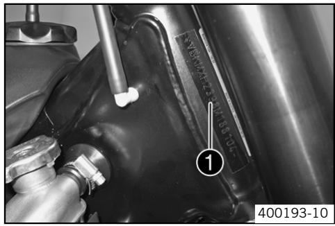
The chassis number 1 is stamped on the right side of the steering head tube.
Type label
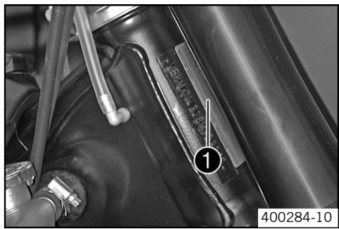
The type label is fixed to the front of the steering head.
Engine number
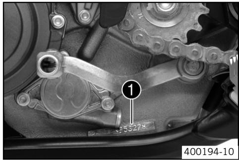
The engine number ① is stamped on the left side of the engine under the engine sprocket.
Fork part number
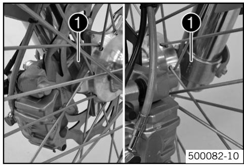
The fork part number ① is stamped on the inner side of the fork stub.
Shock absorber part number
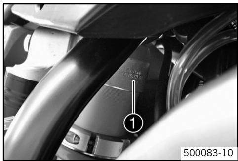
The shock absorber part number ① is stamped on the top of the shock absorber above the adjusting ring on the engine side.
Clutch lever
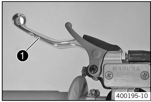
The clutch lever 1 is fitted on the left side of the handlebar. The clutch is hydraulically operated and self-adjusting.
Hot start lever
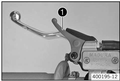
The hot start lever 1 is fitted on the left of the handlebar.
If you pull the hot start lever to the handlebar during the start procedure, a hole is opened in the carburetor to allow the engine to draw in extra air. This gives a leaner fuel-air mixture, which is needed for a hot start.
Possible states
Hot start lever in basic position
Hot start lever pulled
Hand brake lever
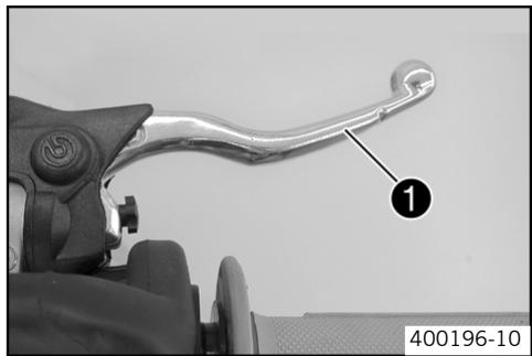
The hand brake lever ① is located on the right side of the handlebar and operates the front wheel brake.
Short circuit button
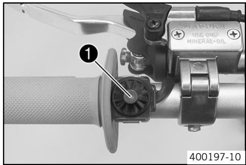
The short circuit button 1 is fitted on the left side of the handlebar.
When you press the short circuit button , the ignition circuit is short-circuited, which stops the engine.
Possible states
Short circuit button in basic position
Short circuit button pressed
Electric starter button
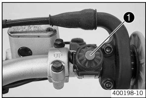
The electric starter button is fitted on the right side of the handlebar. Pressing the electric start button (三) operates the electric starter.
Possible states
- Starter button in basic position
Electric starter button pressed
Fuel tap (450 SX-F, 505 SX-F)
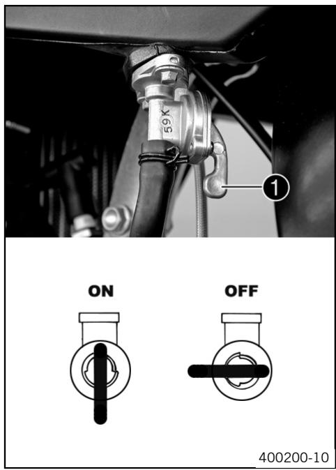
With the tap handle ① on the fuel tap, you can open or close the supply of fuel to the carburetor.
Possible states
Fuel supply closed (OFF)
Fuel supply open (ON)
Fuel tap (450 XC-F, 505 XC-F)
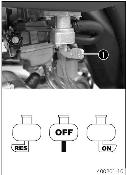
With the tap handle ① on the fuel tap, you can open or close the supply of fuel to the carburetor.
Possible states
- Fuel supply closed (OFF)
Fuel supply open (ON) - Reserve fuel supply open (RES)
Opening filler cap
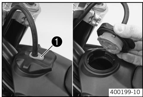
- Press release button ①, turn filler cap counterclockwise and lift it free.
Closing filler cap
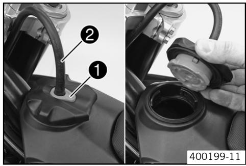
- Replace the filler cap and turn clockwise until the release button locks in place.

Info
Run the fuel tank breather hose 2 without kinks.
Choke
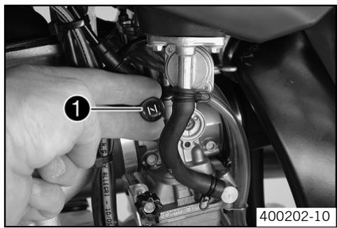
The choke ① is fitted on the left side side of the carburetor.
Activating the choke function frees an opening through which the engine can draw extra fuel. This gives a richer fuel-air mixture, which is needed for a cold start.

Info
If the engine is warm, the choke function must be deactivated.
Possible states
- Choke function activated
- Choke function deactivated
Shift lever
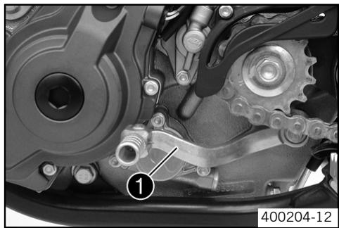
The shift lever 1 is mounted on the left side of the engine.
(450 SX-F, 505 SX-F)
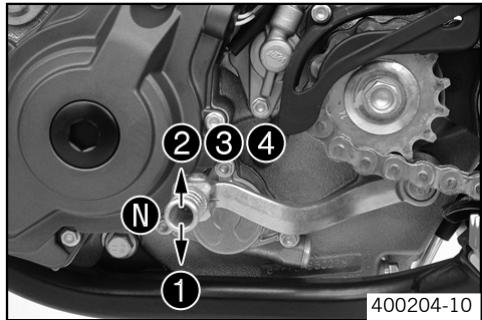
The gear positions can be seen in the photograph.
The neutral or idle position is between the first and second gears.
(450 XC-F, 505 XC-F)
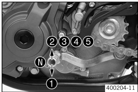
The gear positions can be seen in the photograph.
The neutral or idle position is between the first and second gears.
Foot brake pedal
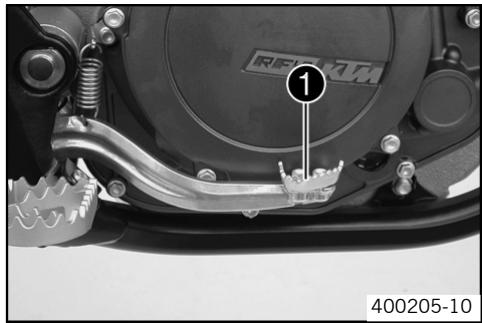
The foot brake pedal ① is located in front of the right footrest and operates the rear wheel brake.
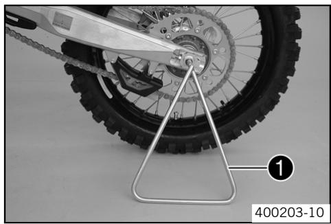
Plug-in stand (450 SX-F, 505 SX-F)
Note
Danger of damage Danger of damage by the motorcycle running away or falling over.
Always place the motorcycle on a firm and even surface.
To park the motorcycle, insert the plug-in stand 1 in the left side of the wheel spindle.

Info
Remove the plug-in stand before the journey.
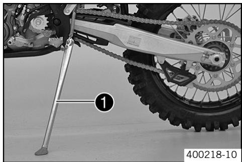
Side stand (450 XC-F, 505 XC-F)
Note
Danger of damage Danger of damage by the motorcycle running away or falling over.
Always place the motorcycle on a firm and even surface.
To park the motorcycle, press the side stand with your foot to the ground and lean the motorcycle on it.
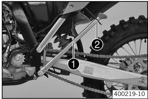
When you are riding, the side stand ① must be folded up and secured with the rubber band ②.
Advice on first use

Danger
Danger of accidents Danger from inadequate traffic experience.
- Do not use the vehicle if you are inexperienced or if you have consumed alcohol or drugs.

Warning
Risk of injury Risk of injury by missing/inadequate protective clothing.
- Wear protective clothing (helmet, boots, gloves, pants and jacket with protectors) every time you ride the motorcycle.

Warning
Danger of crashing Impairment of riding behavior due to different tire tread patterns on front and rear wheels.
The front and rear wheels must be fitted with tires with similar tread patterns to prevent loss of control over the motorcycle.

Warning
Danger of accidents Critical riding behavior due to inappropriate riding.
- Adapt your riding speed to the road conditoins and your riding ability.

Warning
Danger of accidents Accident risk caused by presence of a passenger.
- Your motorcycle is not designed to carry passengers. Do not ride with a passenger.

Warning
Danger of accidents Brake system failure.
If the foot brake pedal is not released, the brake linings drag permanently. The rear brake can fail due to overheating. Take your foot off the foot brake pedal if you do not want to brake.

Warning
Danger of accidents Unstable riding behavior.
- Do not exceed the maximum permitted weight and axle loads.

Warning
Risk of misappropriation Usage by unauthorized persons.
- Never leave the motorcycle while the engine is running. Secure the motorcycle against use by unauthorized persons.

Info
When using your motorcycle, remember that others may feel disturbed by excessive noise.
- Make sure that the pre-delivery inspection work has been carried out by an authorized KTM workshop. You receive a delivery certificate and the service record at vehicle handover.
Before your first trip, read the entire operating instructions carefully.
Get to know the operating elements. - adjust the basic position of clutch lever. (60)
- adjust the basic position of handbrake lever. (39)
- Adjust the basic position of the footbrake lever. (43)
- Get used to handling the motorcycle on a suitable piece of land before making a longer trip.

Info
Your motorcycle is not licensed for use on public roads.
Offroad, you should be accompanied by another person on another machine so that you can help each other.
Try also to ride as slowly as possible and in a standing position to get a better feeling for the vehicle.
- Do not make any offroad trips that over-stress your ability and experience.
- Hold the handlebar firmly with both hands and keep your feet on the footrests when riding.
- Do not make any changes to the motorcycle, and use only KTM approved parts.
If you carry any baggage, make sure it is fixed firmly as close as possible to the center of the vehicle and ensure even weight distribution between the front and rear wheels.

Info
Motorcycles react sensitively to any changes of weight distribution.
- Do not exceed the overall maximum permitted weight and the axle loads. Rules
| Maximum permissible overall weight | 335 kg (738.54 lb.) |
| Maximum permissible front axle load | 145 kg (319.67 lb.) |
| Maximum permissible rear axle load | 190 kg (418.87 lb.) |
Run the engine in.
Running in the engine
- During the running-in phase, do not exceed the specified engine speed and engine performance. Rules
| Maximum engine speed | |
| During the first 3 service hours | 7000 rpm |
| Maximum engine performance during the running-in period | |
| During the first 3 service hours | ≤ 50 % |
| During the next 12 service hours | ≤ 75 % |
- Avoid fully opening the throttle!
Checks before putting into operation

Info
Make sure that the motorcycle is in a perfect technical condition before use.

Info
In the interests of riding safety, make a habit of making a general check before you ride.
- Check the engine oil level. (63)
- Check the chain tension. (34)
- Check the chain dirt accumulation. (33)
- Check the tire condition. (49)
- Checking the tire air pressure. (49)
- Check the front brake brake fluid level. (39)
- Check the rear brake fluid level. (43)
- Check the front brake linings. (40)
- Check the rear brake linings. (44)
- Check braking.
- Check the coolant level. (56)
- Check that all operating elements are correctly adjusted and free to move.
Starting

Danger
Danger of poisoning Exhaust gases are poisonous and can result in unconsciousness or death.
- When running the engine, always make sure there is sufficient ventilation, and do not start or run the engine in a closed space.
Note
Engine failure High engine speeds in cold engines have a negative effect on the service life of the engine.
Always warm up the engine at low engine speeds.

Info
If the motorcycle is unwilling to start, the cause can be old fuel in the float chamber. The flammable elements of the fuel evaporate after a long time of standing.
If the float chamber is filled with fresh fuel, the engine starts immediately.
Press the starter for a maximum of 5 seconds. Wait for a least 5 seconds until trying again.
Conditions
Motorcycle standing still: ≥ 1 week
Empty the carburetor float chamber. (63)
(450 XC-F, 505 XC-F)
- Turn the handle ① of the fuel tap to the ON position. (Figure 400201-10 - 9)
Fuel can flow from the tank to the carburetor.
(450 SX-F, 505 SX-F)
- Turn the handle ① of the fuel tap to the ON position. (Figure 400200-10 - 9)
Fuel can flow from the tank to the carburetor. - Remove the motorcycle from the stand.
- Shift gear to neutral.
Conditions
Engine cold
Pull choke out as far as possible.
Conditions
Engine warm
Pull hot start lever.
Press the electric starter button.

Info
Don't open the throttle.
Starting up
Pull the clutch lever, engage 1st gear, release the clutch lever slowly and simultaneously open the throttle carefully.
Shifting, riding

Warning
Danger of accidents If you change down at high engine speed, the rear wheel can block.
- Do not change into a low gear at high engine speed. The engine races and the rear wheel can block.

Info
If you hear unusual noises while riding, stop immediately, switch off the engine and contact an authorized KTM workshop.
First gear is used for starting off or for steep inclines.
- When conditions allow (incline, road situation, etc.), you can shift into a higher gear. To do so, release the throttle while simultaneously pulling the clutch lever, shift into the next gear, release the clutch and open the throttle.
- If the choke function was activated, deactivate it after the engine has warmed up.
- When you reach maximum speed after fully opening the throttle, turn back the throttle to about 3/4 of its range; the speed hardly drops, but the fuel consumption falls considerably.
Always open the throttle only as much as the engine can handle – abrupt throttle opening increases fuel consumption. - To shift down, brake if necessary and close the throttle at the same time.
Pull the clutch lever and shift into a lower gear, release the clutch lever slowly and open the throttle or shift again. - Switch off the engine if you expect to be standing for a long time. Rules
≥ 2 min
- Avoid frequent and longer slipping of the clutch. This heats the engine oil, the engine and the cooling system.
- Ride with a lower engine speed instead of with a high engine speed and a slipping clutch.
Braking

Warning
Danger of accidents If you brake too hard, the wheels can lock.
- Adapt your braking to the traffic situation and the road conditions.

Warning
Danger of accidents Reduced braking caused by spongy pressure point of front or rear brake.
- Have the brake system checked in an authorized KTM workshop, and do not ride any further.

Warning
Danger of accidents Reduced braking due to wet or dirty brakes.
Clean or dry dirty or wet brakes by riding and braking gently.
- On sandy, wet or slippery surfaces, use the rear brake.
- Braking should always be completed before you go into a bend. Change down to a lower gear appropriate to your road speed.
- On long downhill stretches, use the braking effect of the engine. Change down one or two gears, but do not overstress the engine. In this way, you have to brake far less and the brakes do not overheat.
Stopping, parking

Warning
Danger of burns Some motorcycle components get very hot when the machine is driven.
- Do not touch hot components such as exhaust system, radiator, engine, shock absorber and brakes. Allow these components to cool down before starting work on them.
Note
Danger of damage Danger of damage by the motorcycle running away or falling over.
Always place the motorcycle on a firm and even surface.
Note
Fire hazard Some components (engine, radiator and exhaust system) get very hot when the engine is running.
-
Do not place the motorcycle where there are flammable or explosive substances.
-
Apply the brakes and shift into neutral.
- To switch off the engine from idle speed, press the short circuit button until the engine stops.
- Close the fuel tap, and park the motorcycle on firm ground.
Refueling

Danger
Fire hazard Fuel can easily catch fire.
- Never fill up the motorcycle near open flames or burning cigarettes, and always switch off the engine first. Be careful that no fuel is spilt, especially on hot motorcycle components. Clean up spilt fuel immediately.
Fuel in the fuel tank expands when warm and can escape if the tank is overfilled. See specifications on filling up with fuel.

Warning
Danger of poisoning Fuel is poisonous and a health hazard.
- Avoid contact between fuel and skin, eyes and clothing. Do not inhale fuel vapors. If fuel gets into your eyes, rinse immediately with water and contact a doctor. Wash affected skin areas immediately with soap and water. If fuel is swallowed, contact a doctor immediately. Change clothing that has come into contact with fuel.

Warning
Environmental hazard Improper handling of fuel is a danger to the environment.
- Do not allow fuel to get into the ground water, the ground, or the sewage system.
- Open the filler cap. (9)
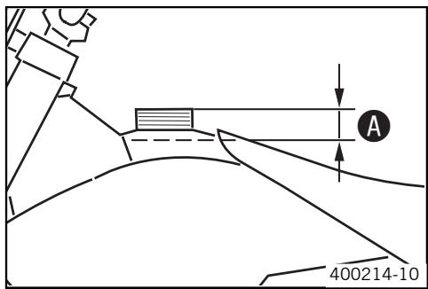
- Fill the fuel tank with fuel up to measurement A . Rules
| Measurement of A: | 35 mm (1.38 in) | |
| Tank capacity | 8.2 l (2.17 US gal) (450 SX-F, 505 SX-F) | Super unleaded (← 82) |
| 9.2 l (2.43 US gal) (450 XC-F, 505 XC-F) | Super unleaded (← 82) | |
- Close the filler cap. (10)
Important maintenance work to be carried out by an authorized KTM workshop.
| After 3 service hours / 20 liters of fuel | Every 10 service hours / 70 liters of fuel / after each race | Every 30 service hours / 210 liters of fuel | ||
| Engine | Change the engine oil and oil filter, and clean the oil screen. (64) | ● | ● | |
| Replace spark plug. | ● | |||
| Check and adjust valve clearance. | ● | ● | ||
| Check engine mounting screws for tightness. | ● | ● | ||
| Clean spark plug connectors and check for tightness. | ● | ● | ||
| Check shift lever screw for tightness. | ● | ● | ||
| Carburetor | Check carburetor connection boots for cracks and leakage. | ● | ||
| Check vent hoses for damage and routing without sharp bends. | ● | ● | ||
| Check idle. | ● | ● | ||
| Attachments | Check the cooling system for leakage. | ● | ● | |
| Check the antifreeze and coolant level. (55) | ● | ● | ||
| Check the exhaust system for leakage and looseness. | ● | |||
| Check Bowden cables for damage, smooth operation and routing without sharp bends. | ● | ● | ||
| Check the fluid level of the hydraulic clutch. (60) | ● | ● | ||
| Clean the air filter. (60) | ● | ● | ||
| Check cables for damage and routing without sharp bends. | ● | |||
| Brakes | Check the front brake linings. (40) | ● | ● | |
| Check the rear brake linings. (44) | ● | ● | ||
| Check the brake discs. (38) | ● | ● | ||
| Check the front brake brake fluid level. (39) | ● | ● | ||
| Check the rear brake fluid level. (43) | ● | ● | ||
| Check brake lines for damage and leakage. | ● | ● | ||
| Check the free play of the hand brake lever. (39) | ● | ● | ||
| Check the free play of the foot brake lever. (42) | ● | ● | ||
| Check brake system function. | ● | ● | ||
| Check screws and guide bolts of brake system for tightness. | ● | ● | ||
| Chassis | Check shock absorber and fork for leakage and functioning. | ● | ● | |
| Clean dust boots of fork legs. (26) | ● | |||
| Bleed fork legs. (26) | ● | |||
| Check swingarm bearing. | ● | |||
| Check play of steering head bearing. (27) | ● | ● | ||
| Check all screws to see if they are tight. | ● | ● | ||
| Wheels | Check the spoke tension. (50) | ● | ● | |
| Check rim run-out. | ● | ● | ||
| Check the tire condition. (49) | ● | ● | ||
| Checking the tire air pressure. (49) | ● | ● | ||
| Check the chain wear. (35) | ● | ● | ||
| Check the chain tension. (34) | ● | ● | ||
| Clean the chain. (33) | ● | ● | ||
| Check wheel bearing for play. | ● | ● | ||
| Clean and grease adjusting screws of chain adjuster. | ● | ● |
Important maintenance work to be carried out by an authorized KTM workshop. (as additional order)
| Every 10 service hours / 70 liters of fuel / after each race | Every 20 service hours / 140 liters of fuel | Every 40 service hours / 270 liters of fuel | annually | every 2 years | |
| Carry out a complete fork service. | ● | ||||
| Carry out a complete shock absorber service. | ● | ||||
| Grease the steering head bearing. (▼ 31) | ● | ||||
| Clean and adjust carburetor. | ● | ||||
| Treat electric contacts with contact spray. | ● | ||||
| Change hydraulic clutch fluid. | ● | ||||
| Change brake fluid. | ● | ||||
| Check wear of clutch discs. | ● | ||||
| Check long clutch springs. | ● | ||||
| Check clutch slave cylinder for dents. | ● | ||||
| Check outer clutch hub for dents. | ● | ||||
| Check cylinder wear and change pistons. | ● | ||||
| Check camshaft wear. (visual check) | ● | ||||
| Check wear of valve spring seat. | ● | ||||
| Check wear of valve guides. | ● | ||||
| Change valves. | ● | ||||
| Change valve springs. | ● | ||||
| Check the timing-chain tensioner function. | ● | ||||
| Check crankshaft and crankshaft journal for run-out. | ● | ||||
| Change conrod bearing. | ● | ||||
| Check piston pin bearing. | ● | ||||
| Change the crankshaft main bearing. | ● | ||||
| Check wear of all transmission components including shafts and bearings. | ● | ||||
| Check long bypass valve spring. | ● | ||||
| Change glass fiber yarn filling of main silencer. (▼ 59) | ● | ||||
| Replace foot brake cylinder seals. | ● | ||||
| Check carburetor components. | ● |
Important checks and maintenance work to be carried out by the rider.
| Conditions:For use on offroad terrainaccording to requirements | |
| Check the engine oil level. (63) | ● |
| Check the front brake brake fluid level. (39) | ● |
| Check the rear brake fluid level. (43) | ● |
| Check the front brake linings. (40) | ● |
| Check the rear brake linings. (44) | ● |
| Check and adjust Bowden cables. | ● |
| Bleed fork legs. (26) | ● |
| Clean dust boots of fork legs. (26) | ● |
| Clean the chain. (33) | ● |
| Check the chain tension. (34) | ● |
| Check the chain wear. (35) | ● |
| Check rear sprocket / engine sprocket for wear. (35) | ● |
| Clean the air filter. (60) | ● |
| Checking the tire air pressure. (49) | ● |
| Check the tire condition. (49) | ● |
| Check the coolant level. (56) | ● |
| Empty the carburetor float chamber. (63) | ● |
| Check that all operating elements for smooth operation. | ● |
| Check braking. | ● |
| Check all screws, nuts and hose clamps regularly for tightness. | ● |
Jacking up the motorcycle
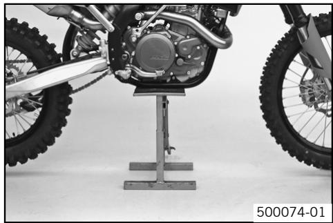
Note
Danger of damage Danger of damage by the motorcycle running away or falling over.
Always place the motorcycle on a firm and even surface.
- Jack up the motorcycle underneath the engine. The wheels must no longer touch the ground.
Work stand (54829055000)
- Secure the motorcycle against falling over.
Removing the motorcycle from the work stand
Note
Danger of damage Danger of damage by the motorcycle running away or falling over.
Always place the motorcycle on a firm and even surface.
- Remove the motorcycle from the work stand.
- Remove the work stand.
Checking the basic chassis setting with the rider's weight

Info
When adjusting the basic chassis setting, first adjust the shock absorber and then the fork.
For optimal motorcycle riding characteristics and to avoid damage to forks, shock absorbers, swing arm and frame, the basic settings of the suspension components must match your body weight.
As delivered, KTM offroad motorcycles are adjusted for a standard rider weight (with full protective clothing).
Standard rider weight
75...85 kg (165.34...187.39 lb.)
If your weight is above or below the standard range, you have to adjust the basic setting of the suspension components accordingly. Small weight differences can be compensated by adjusting the spring preload, but in the case of large weight differences, the springs must be replaced.
Compression damping of shock absorber
The shock absorber can regulate compression damping in low- and high-speed range separately (Dual Compression Control).
The term low and high speed refers to the movement of the shock absorber during compression and not the riding speed of the motorcycle.
The low- and high-speed technology works non-specifically.
Adjusting high-speed compression damping of the shock absorber

Danger
Danger of accidents The shock absorber is under high pressure.
The shock absorber is filled with highly compressed nitrogen, so never dismantle the shock absorber or carry out any maintenance on it yourself.

Info
The high-speed setting can be seen during the fast compression of the shock absorber.
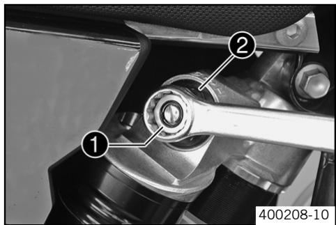
- Turn the adjusting screw ① clockwise with a ring wrench until it stops.

Info
Do not loosen nut 2!
- Turn back counterclockwise the number of turns corresponding to the shock absorber type. Rules
| Compression damping, high-speed (450 SX-F, 505 SX-F) | |
| Comfort | 1 turn |
| Standard | 1 turn |
| Sport | 3/4 turn |
| Compression damping, high-speed (450 XC-F, 505 XC-F) | |
| Standard | 1 turn |

Info
Turn clockwise to increase damping, turn counterclockwise to reduce suspension damping.
Adjusting the low-speed compression damping of the shock absorber

Danger
Danger of accidents The shock absorber is under high pressure.
The shock absorber is filled with highly compressed nitrogen, so never dismantle the shock absorber or carry out any maintenance on it yourself.

Info
The low-speed setting can be seen during the slow to normal compression of the shock absorber.
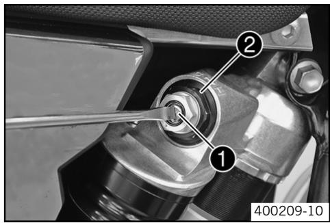
- Turn the adjusting screw ① clockwise with a screwdriver until it stops.

Info
Do not loosen nut 2!
- Turn back counterclockwise the number of clicks corresponding to the shock absorber type. Rules
| Compression damping, low-speed (450 SX-F, 505 SX-F) | |
| Comfort | 16 clicks |
| Standard | 14 clicks |
| Sport | 12 clicks |
| Compression damping, low-speed (450 XC-F, 505 XC-F) | |
| Standard | 15 clicks |

Info
Turn clockwise to increase damping, turn counterclockwise to reduce suspension damping.
Adjusting rebound damping of the shock absorber

Danger
Danger of accidents The shock absorber is under high pressure.
The shock absorber is filled with highly compressed nitrogen, so never dismantle the shock absorber or carry out any maintenance on it yourself.
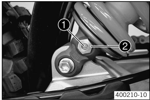
Turn the adjusting screw 1 clockwise until it stops.

Info
Do not loosen nut 2!
- Turn back counterclockwise the number of clicks corresponding to the shock absorber type.
Rules
| Rebound damping (450 SX-F, 505 SX-F) | |
| Comfort | 25 clicks |
| Standard | 23 clicks |
| Sport | 22 clicks |
| Rebound damping (450 XC-F, 505 XC-F) | |
| Standard | 23 clicks |

Info
Turn clockwise to increase damping, turn counterclockwise to reduce suspension damping.
Measuring rear wheel sag unloaded
- Jack up the motorcycle. (20)
Measure the distance - as vertical as possible - between the rear axle and a fixed point, for example, a mark on the side cover. - Make a note of the value as measurement A.
- Remove the motorcycle from the work stand. (20)
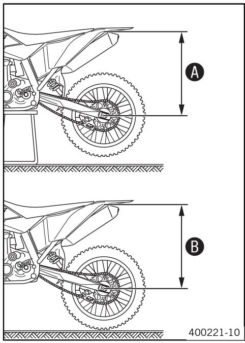
Checking static sag of the shock absorber
Measure distance A of rear wheel unloaded. (22)
- Ask someone to help you by holding the motorcycle upright.
- Measure the distance between the rear axle and the fixed point again.
- Make a note of the value as measurement ⑧.

Info
The static sag is the difference between measurements A and B .
- Check the static sag.
Static sag
33 mm (1.3 in)
If the static sag is less or more than the specified value:
- Adjust the spring preload of the shock absorber. (23)
Check the riding sag of the shock absorber.
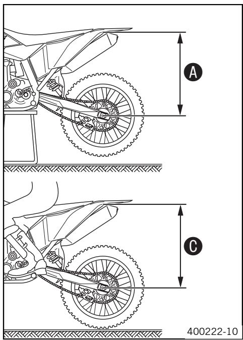
Measure distance A of rear wheel unloaded. (22)
- With another person holding the motorcycle, sit on the saddle with full protective clothing in a normal sitting position (feet on footrests) and bounce up and down a few times until the rear suspension levels out.
- The other person now has to measure the distance between the rear axle and a fixed point.
- Make a note of the value as measurement .

Info
The riding sag is the difference between measurements A and C .
- Check the riding sag.
| Riding sag (450 SX-F, 505 SX-F) | 107 mm (4.21 in) |
| Riding sag (450 XC-F, 505 XC-F) | 110 mm (4.33 in) |
If the riding sag differs from the specified measurement:
- Adjust the riding sag. (24)
Adjusting spring preload of the shock absorber

Danger
Danger of accidents The shock absorber is under high pressure.
The shock absorber is filled with highly compressed nitrogen, so never dismantle the shock absorber or carry out any maintenance on it yourself.

Info
Before changing the spring preload, make a note of the present setting, e.g., by measuring the length of the spring.
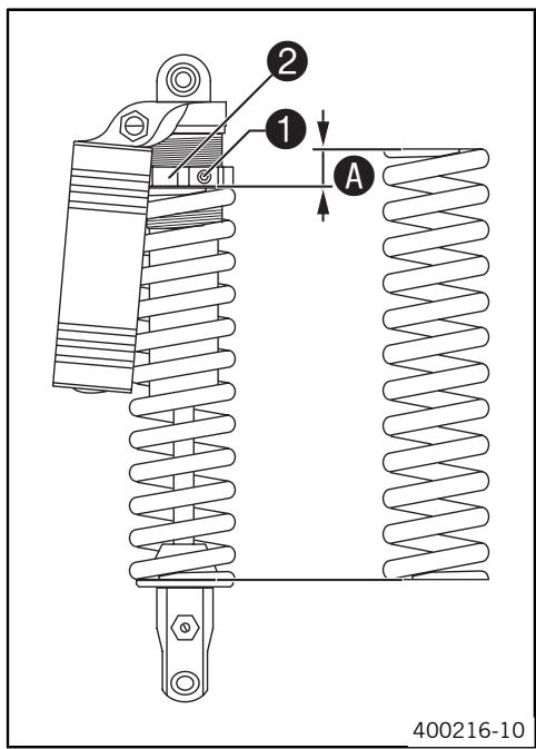
- Remove shock absorber. (24)
After removing the shock absorber, clean it thoroughly. - Loosen screw ①.
- Turn adjusting ring ② until the spring is no longer under tension.
| Combination wrench (50329080000) |
| Hook wrench (T106S) |
Measure the overall spring length when not under tension.
- Tighten the spring by turning adjusting ring ① to measurement A. Rules
| Spring preload | 7 mm (0.28 in) |
- Tighten screw ②. Rules
| Screw, shock absorber adjusting ring | M6 | 5 Nm (3.69 lbf ft) |
- Installing shock absorber (24)
Adjusting riding sag
- Remove shock absorber. (24)
After removing the shock absorber, clean it thoroughly. - Choose and fit a suitable spring. Rules
| Spring rate | |
| Weight of rider: 65...75 kg (143.3...165.34 lb.) | 66 N/mm (376.87 lb/in) |
| Weight of rider: 75...85 kg (165.34...187.39 lb.) | 69 N/mm (394 lb/in) |
| Weight of rider: 85...95 kg (187.39...209.44 lb.) | 72 N/mm (411.13 lb/in) |

Info
The spring rate is shown on the outside of the spring.
- Installing shock absorber (24)
- Check the static sag of the shock absorber. (22)
- Adjust the rebound damping of the shock absorber. (21)
Removing the shock absorber
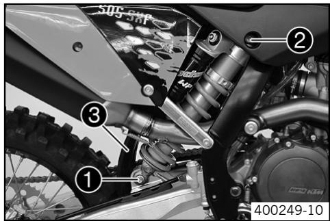
- Jack up the motorcycle. (20)
- Remove screw ① and lower the rear wheel with the swing arm as far as possible without blocking the rear wheel. Fix the rear wheel in this position.
- Remove screw ②, push splash protector ③ to the side, and remove the shock absorber.
Installing shock absorber
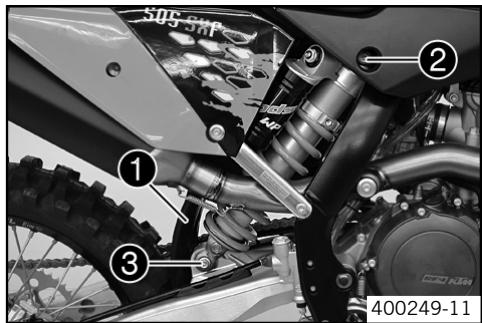
- Check parts for damage and wear. Replace damaged or worn parts.
- Push splash protector ① to the side and position the shock absorber. Mount and tighten screw ②. Rules
| Screw, top shock absorber | M12 | 80 Nm (59.01 lbf ft) | Loctite® 243TM (€ 84) |
- Mount and tighten screw ⑨ . Rules
| Screw, bottom shock absorber | M12 | 80 Nm (59.01 lbf ft) | Loctite® 243TM (€ 84) |
The heim joint for the shock absorber at the swing arm is Teflon coated. It must not be greased with grease or with other lubricants. Lubricants dissolve the Teflon coating, thereby drastically reducing the service life.
- Remove the motorcycle from the work stand. (20)
Checking basic setting of fork
Info
For various reasons, no exact riding sag can be determined for the forks.
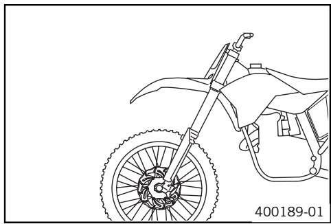
As with the shock absorber, smaller weight differences can be compensated by the spring preload.
However, if your fork is often overloaded (hard end stop on compression), you must fit harder springs to avoid damage to the fork and frame.
Adjusting compression damping of fork

Info
The hydraulic compression damping determines the fork suspension behavior.
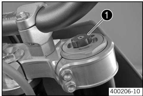
- Adjusting screws ① clockwise until they stop.

Info
The adjusting screws 1 are located at the top end of the fork legs.
Make the same adjustment on both fork legs.
- Turn back counterclockwise the number of clicks corresponding to the fork type. Rules
| Compression damping (450 SX-F, 505 SX-F) | |
| Comfort | 16 clicks |
| Standard | 14 clicks |
| Sport | 12 clicks |
| Compression damping (450 XC-F, 505 XC-F) | |
| Standard | 20 clicks |

Info
Turn clockwise to increase damping, turn counterclockwise to reduce suspension damping.
Adjusting rebound damping of fork

Info
The hydraulic rebound damping determines the fork suspension behavior.
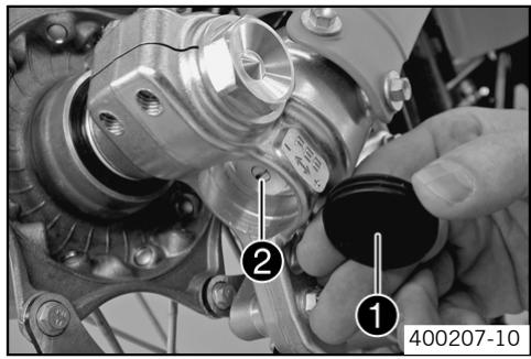
- Remove protection covers 1.
Turn the adjusting screws 2 clockwise until they stop.

Info
The adjusting screws 2 are located at the bottom end of the fork legs. Make the same adjustment on both fork legs.
- Turn back counterclockwise the number of clicks corresponding to the fork type. Rules
| Rebound damping (450 SX-F, 505 SX-F) | |
| Comfort | 22 clicks |
| Standard | 21 clicks |
| Sport | 21 clicks |
| Rebound damping (450 XC-F, 505 XC-F) | |
| Standard | 21 clicks |

Info
Turn clockwise to increase damping, turn counterclockwise to reduce suspension damping.
Mount protection covers 1.
Bleeding fork legs
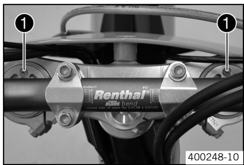
- Jack up the motorcycle. (20)
- Remove bleeder screws briefly.
Any excess pressure escapes from the interior of the fork.
Mount and tighten bleeder screws.
- Remove the motorcycle from the work stand. (20)
Cleaning dust boots of fork legs
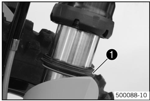
- Jack up the motorcycle. (20)
- Loosen the fork protection. (26)
Push dust boots ① of both fork legs downwards.

Info
The dust boots should remove dust and coarse dirt particles from the fork tube. Over time, dirt can penetrate behind the dust boots. If this dirt is not removed, the oil seals behind can start to leak.

Warning
Danger of accidents Reduced braking due to oil or grease on the brake discs.
- Always keep the brake discs free of oil and grease, and clean them with brake cleaner when necessary.
Clean and oil the dust boots and inner fork tube of both fork legs.
Universal oil spray (84)
- Press the dust boots back into their normal position.
- Remove excess oil.
Loosening the fork protection
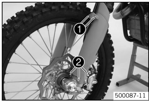
- Remove screws and take off clamp.
- Remove screws ② on left fork leg. Push the fork protection downwards.
- Remove the screws on the right fork leg. Push the fork protection downwards.
Positioning the fork protection
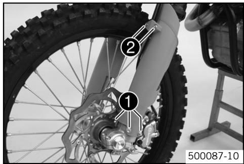
- Position the fork protection on the left fork leg. Mount and tighten screws 1. Rules
| Remaining screws, chasis | M6 | 10 Nm (7.38 lbf ft) |
Position brake line. Put the clamp on, mount and tighten screws ②.
- Position the fork protection on the right fork leg. Mount and tighten screws. Rules
| Remaining screws, chasis | M6 | 10 Nm (7.38 lbf ft) |
Checking play of steering head bearing

Warning
Danger of accidents Unsafe riding behavior due to incorrect steering head bearing play.
- The steering head bearing play should be adjusted immediately in an authorized KTM workshop.

Info
If the bike is driven for a longer time with play in the steering head bearing, the bearing and the bearing seats in the frame can be damaged after time.
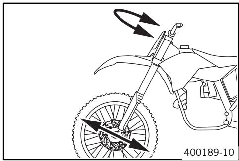
- Jack up the motorcycle. (20)
- Move the handlebar to the straight-ahead position. Move the fork legs to and fro in the direction of travel.
No play should be noticeable in the steering head bearing.
If there is noticeable play present:
- Adjust play of the steering head bearing (27)
- Move the handlebar to and fro over the entire steering range.
The handlebar must be able to move easily over the entire steering range. No resting locations should be noticeable.
If click positions are noticeable:
- Adjust play of the steering head bearing (27)
-
Check the steering head bearing and replace if required.
-
Remove the motorcycle from the work stand. (20)
Adjusting play of steering head bearing
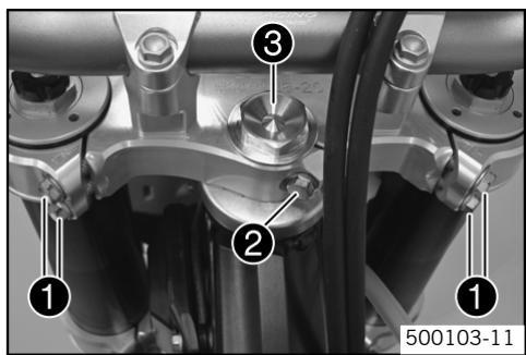
- Jack up the motorcycle. (20)
- Loosen screw ①. Remove screw ②.
- Loosen and retighten screw ③.
Rules
| Screw, top steering head | M20x1,5 | 10 Nm (7.38 lbf ft) |
Using a plastic hammer, tap lightly on the upper triple clamp to avoid strains.
- Fully tighten screw 1.
Rules
| Screw, top triple clamp | M8 | 17 Nm (12.54 lbf ft) |
Mount and tighten screw ②.
Rules
| Screw, top steering stem | M8 | 17 Nm (12.54 lbf ft) | Loctite® 243TM (€ 84) |
- Check play of steering head bearing. (27)
Fork offset
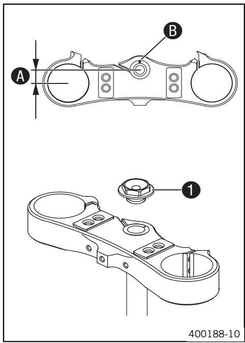
You can see the currently set offset if you remove screw 1.
The fork offset A has an impact on the handling of the vehicle. It is calculated from the center of the fork leg to the center of the steering head bearing.
The fork offset can optionally be adjusted.
Marking 3 to the front gives greater stability on fast racetracks.
| Fork offset: | 18 mm (0.71 in) |
Marking 3 to the rear (condition at delivery) gives better handling in bends.
| Fork offset: | 20 mm (0.79 in) |
Setting the fork offset
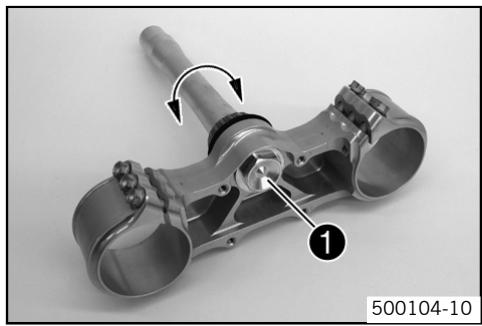
- Remove the lower triple clamp. (30)
- Remove screw ①. Remove the steering stem.
Clean the parts and check for damage. - Rotate the steering stem 180^ and insert into the triple clamp. Mount and tighten screw ①. Rules
| Screw, bottom steering head | M20x1,5 | 60 Nm (44.26 lbf ft) | Loctite® 243™ (€ 84) |
Install the lower triple clamp. (30)
Removing the fork legs
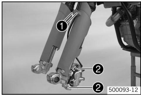
- Remove front wheel. (46)
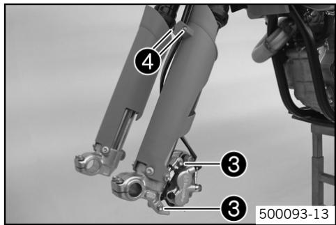
- Remove screws and take off clamp.
- Remove screws ② and take off brake caliper.
Hang the brake caliper and the brake line loosely to the side.
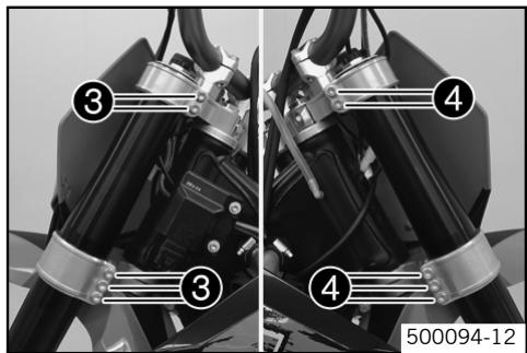
- Loosen screw ③. Remove the fork leg on the left.
- Loosen screw ④. Remove the fork leg on the right.
Installing the fork legs
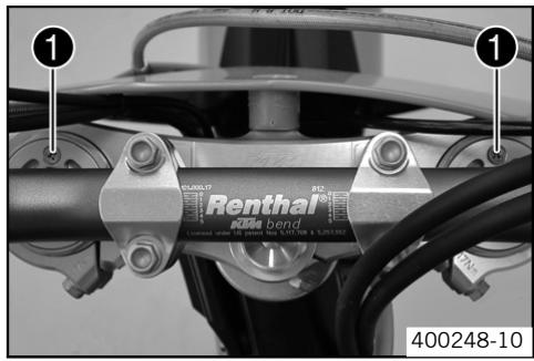
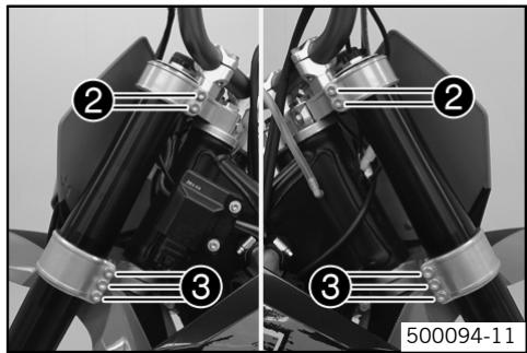
- Check parts for damage and wear. Replace damaged or worn parts.
Position the fork legs.

Info
The topmost sunk nut in the fork leg must be flush to the upper edge of the upper triple clamp.
Position the bleeder screw 1 to the front.
- Fully tighten screw ②.
Rules
| Screw, top triple clamp | M8 | 17 Nm (12.54 lbf ft) |
- Fully tighten screw ⑥.
Rules
| Screw, bottom triple clamp | M8 | 12 Nm (8.85 lbf ft) |
Position brake caliper, mount and tighten screws ③.
Rules
| Screw, front brake caliper | M8 | 25 Nm (18.44 lbf ft) | Loctite® 243TM (€ 84) |
Position brake line. Put the clamp on, mount and tighten screws 4.
- Fit front wheel. (47)
Removing the fork protector
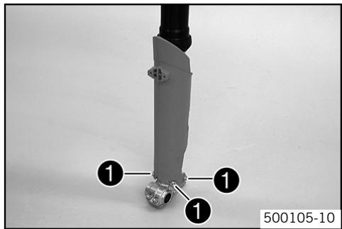
- Remove the fork legs. (28)
- Remove screws on the left fork leg. Remove the fork protector upwards.
- Remove the screws on the right fork leg. Remove the fork protector upwards.
Installing the fork protector
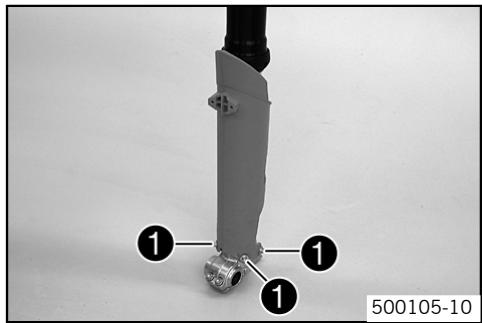
- Check parts for damage and wear. Replace damaged or worn parts.
- Position the fork protection on the left fork leg. Mount and tighten screws 1. Rules
| Remaining screws, chasis | M6 | 10 Nm (7.38 lbf ft) |
Position the fork protection on the right fork leg. Mount and tighten screws.
Rules
| Remaining screws, chas-sis | M6 | 10 Nm (7.38 lbf ft) |
Install the fork legs. (29)
Removing the lower triple clamp
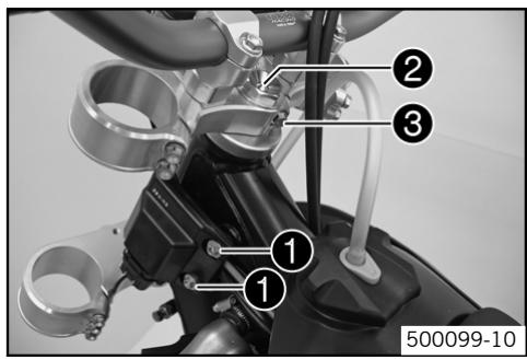
- Remove the fork legs. (28)
- Dismount the start number plate (31)
- Dismount the front fender (31)
- Remove screws 1 and hang the CDI control unit to the side.

Info
Do not unplug the CDI control unit.
- Remove screw ②. Remove screw ③, take off top triple clamp with the handlebar and place it on one side.

Info
Protect the motorcycle and its attachments from damage by covering them. Do not bend the cables and lines.
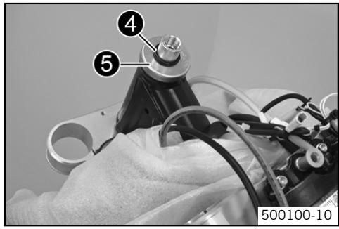
- Remove o-ring 4. Remove protector ring 5.
- Remove the lower triple clamp with the steering stem.
- Remove the upper steering head bearing.
Installing the lower triple clamp
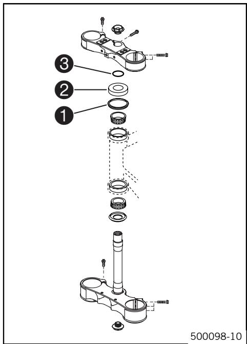
Clean the bearing and sealing elements, check for damage, and grease.
Long-life grease (84)
- Insert the lower triple clamp with the steering stem. Mount the upper steering head bearing.

Info
Check whether the top steering head seal is correctly positioned.
Push up protective ring 2 and o-ring 3.
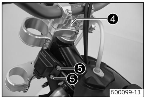
Position the upper triple clamp with the steering.
- Mount and tighten screw 4. Rules
| Screw, top steering head | M20x1,5 | 10 Nm (7.38 lbf ft) |
- Position the clutch line, wiring harness and CDI control unit. Mount and tighten screws .
Rules
| Remaining screws, chas-sis | M6 | 10 Nm (7.38 lbf ft) |
Install front fender. (31)
- Fit the start number plate. (32)
Install the fork legs. (29)
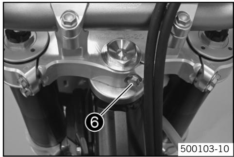
- Mount and tighten screw ⑥ . Rules
| Screw, top steering stem | M8 | 17 Nm (12.54 lbf ft) | Loctite® 243™ (← 84) |
- Check the cable harness, cable, brake and clutch line for free movement and free laying
- Check play of steering head bearing. (27)
Greasing the steering head bearing
- Remove the lower triple clamp. (30)
Install the lower triple clamp. (30)
Dismounting the front fender
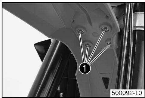
- Remove screws ①. Remove the front fender
- Make sure that the distance bushing remains in place.
Installing the front fender
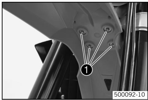
- Check parts for damage and wear. Replace damaged or worn parts.
- Make sure that the distance bushes are mounted in the fender.
- Position the front fender. Mount and tighten screws 1. Rules
| Remaining screws, chasis | M6 | 10 Nm (7.38 lbf ft) |

Info
Take care with the contact between the holding lugs and the start number plate.
Dismount the start number plate
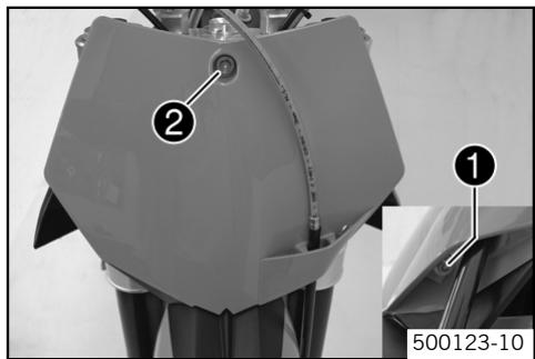
- Remove screw ① and take off clamp.
- Remove screw ②. Remove the start number plate.
Fitting the start number plate
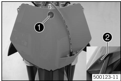
- Check parts for damage and wear. Replace damaged or worn parts.
- Position the start number plate. Mount and tighten screw ①. Rules
| Remaining screws, chasis | M6 | 10 Nm (7.38 lbf ft) |

Info
Take care with the contact of the holding lug at the fender.
Position brake line. Put the clamp on, mount and tighten screw ②.
Handlebar position
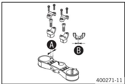
On the upper triple clamp, there are 2 holes at a distance of A to each other.
| Drilling distance A: | 15 mm (0.59 in) |
The holes on the handlebar support are placed at a distance of 3 from the center.
| Drilling distance B: | 3.5 mm (0.14 in) |
The handlebar can be mounted in 4 different positions. This enables you to mount the handlebar in the position most suitable for the rider.
Adjusting handlebar position
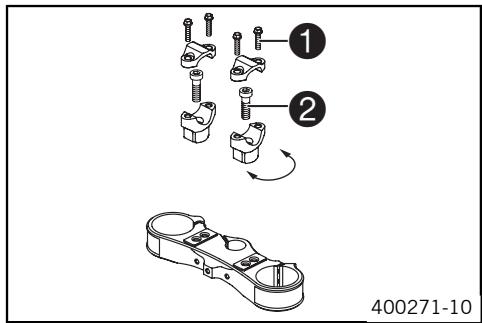
- Remove the four screws ①. Remove the handlebar clamp. Remove the handlebar and lay it to one side.
Info Protect the motorcycle and its attachments from damage by covering them. Do not bend the cables and lines.
- Remove the two screws ② . Remove the handlebar support.
- Place the handlebar support in the required position. Fit and tighten the two screws ②.
Rules
| Screw, handlebar support | M10 | 40 Nm (29.5 lbf ft) | Loctite® 243TM (€ 84) |

Info
Position the left and right handlebar supports evenly.
Position the handlebar.

Info
Make sure cables and wiring are positioned correctly.
- Position the handlebar clamp. Fit and evenly tighten the four screws ①. Rules
| Screw, handlebar clamp | M8 | 20 Nm (14.75 lbf ft) |
Checking gas Bowden cable route
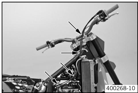
- The two gas Bowden cables must run parallel behind the handlebar down to the frame. They must be routed directly on the frame above the tank bearing to the carburetor.
Checking play in gas Bowden cable
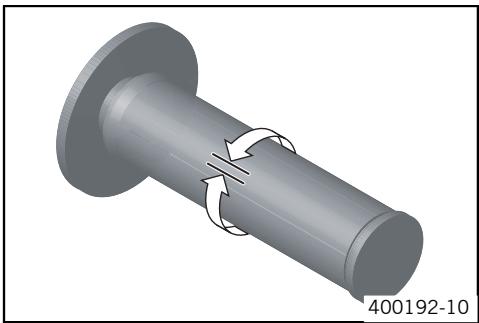
- Move the handlebar to the straight-ahead position. Move the throttle grip backwards and forwards to ascertain the play in the gas Bowden cable. Rules
Play in gas Bowden cable
3...5 mm (0.12...0.2 in)
If the gas Bowden cable play does not meet specifications:
- Adjust the play in the gas Bowden cable. (33)

Danger
Danger of poisoning Exhaust gases are poisonous and can result in unconsciousness or death.
-
When running the engine, always make sure there is sufficient ventilation, and do not start or run the engine in a closed space.
-
Start the engine and let it run idle. Move the handlebar to and fro over the entire steering range.
The idle speed must not change.
If the idle speed changes:
- Adjust the play in the gas Bowden cable. (33)
Adjusting play in gas Bowden cable

- Dismount the fuel tank. (53)
- Check gas Bowden cable route. (32)
- Move the handlebar to the straight-ahead position.
Push back bellows 1. - Loosen nut ②. Turn adjusting screw ③ in as far as possible.
- Loosen nut 4. Turn adjusting screw ⑤ so that there is play in the gas Bowden cable at the throttle grip. Rules
Play in gas Bowden cable
3...5 mm (0.12...0.2 in)
- Tighten nut 4.
- Press and hold the throttle grip in the closed setting. Turn adjusting screw ③ out until there is no play in the Bowden cable ⑥ .
- Tighten nut ②.
Push bellows on. Check the throttle grip for smooth operation.
Install the fuel tank. (54)
Checking chain dirt
- Check the chain for coarse dirt accumulation.
If the chain is very dirty:
Clean the chain. (33)
Cleaning the chain

Warning
Danger of accidents Oil or grease on the tires reduces their grip.
- Remove oil and grease with a suitable cleaning material.

Warning
Danger of accidents Reduced braking due to oil or grease on the brake discs.
Always keep the brake discs free of oil and grease, and clean them with brake cleaner when necessary.

Warning
Environmental hazard Problem materials cause environmental damage.
- Dispos of oil, grease, filters, fuel, cleaning substances, brake fluid, batteries, etc. according to regulations.

Info
The service life of the chain depends largely on its maintenance.
Clean the chain regularly and then treat with chain spray.
Chain cleaner (84) Offroad chain spray 84
Checking the chain tension

Warning
Danger of accidents Danger caused by incorrect chain tension.
- If the chain tension is too high, the components of the secondary power train (chain, engine sprocket, rear sprocket, bearings in transmission and rear wheel) are under additional load. Apart from premature wear, in extreme cases the chain can rupture or the countershaf of the transmission can break. On the other hand, if the chain is loose, it can fall off the engine sprocket or the rear sprocket and block the rear wheel or damage the engine. Check for correct chain tension and adjust if necessary.
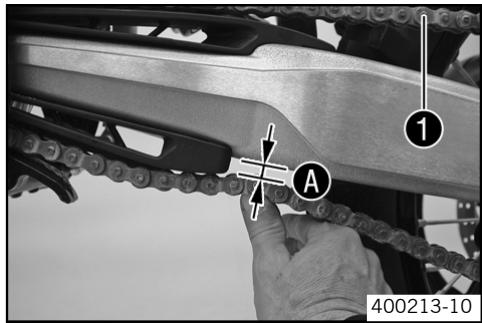
- Jack up the motorcycle. (20)
- Push the chain at the end of the chain sliding component upwards to measure the chain tension .

Info
The upper chain section 1 must be taut.
Chain wear is not always even, so you should repeat this measurement at different chain positions.
Chain tension
8...10 mm (0.31...0.39 in)
If the chain tension does not meet specifications: - Adjusting chain tension - after checking (36)
- Remove the motorcycle from the work stand. (20)
Checking the chain tension - fitting rear wheel

Warning
Danger of accidents Danger caused by incorrect chain tension.
- If the chain tension is too high, the components of the secondary power train (chain, engine sprocket, rear sprocket, bearings in transmission and rear wheel) are under additional load. Apart from premature wear, in extreme cases the chain can rupture or the countershaf of the transmission can break. On the other hand, if the chain is loose, it can fall off the engine sprocket or the rear sprocket and block the rear wheel or damage the engine. Check for correct chain tension and adjust if necessary.
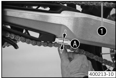
- Make sure that the chain adjusters are fitted correctly on the adjusting screws.
- Push the chain at the end of the chain sliding component upwards to measure the chain tension A .

Info
The upper chain section 1 must be taut.
Chain wear is not always even, so you should repeat this measurement at different chain positions.
Chain tension
8...10 mm (0.31...0.39 in)
If the chain tension does not meet specifications:
- Adjust the chain tension when fitting rear wheel. (37)
Checking rear sprocket / engine sprocket for wear
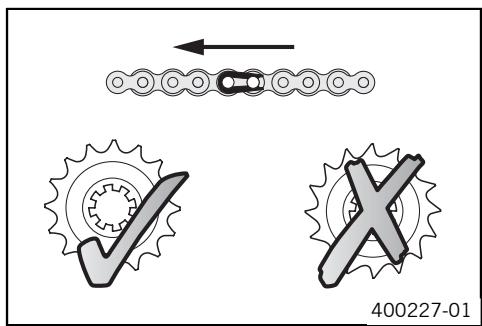
- Check rear sprocket / engine sprocket for wear.
If the rear sprocket / engine sprocket are worn:
- Replace rear sprocket / engine sprocket.

Info
When fitting the chain joint, always make sure that the closed side of the joint faces forward (riding direction).
The engine sprocket, rear sprocket and chain should always be replaced together.
- Check rear sprocket guides to see whether they are firmly seated.
Checking chain wear
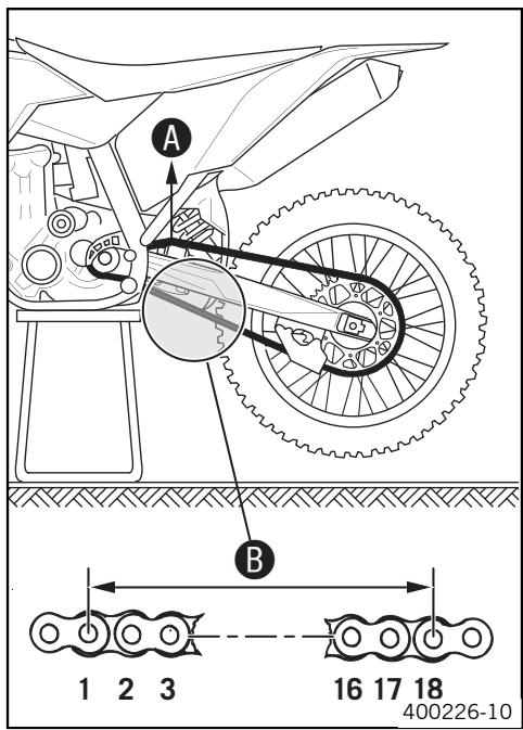
- Jack up the motorcycle. (20)
- Shift to neutral and pull the upper chain length with the specified tension A. Rules
Chain tension
10...15 kg (22.05...33.07 lb.)
Measure the distance of 18 chain links in the lower chain section.

Info
Chain wear is not always even, so you should repeat this measurement at different chain positions.
Maximum distance 3 at the longest chain section:
272 mm (10.71 in)
If the distance B is greater than the specified measurement:
- Replace the chain.

Info
When you replace the chain, you should also replace rear sprocket and engine sprocket.
New chains wear out faster on old, worn sprockets.
- Remove the motorcycle from the work stand. (20)
Adjusting chain tension

Warning
Danger of accidents Danger caused by incorrect chain tension.
- If the chain tension is too high, the components of the secondary power train (chain, engine sprocket, rear sprocket, bearings in transmission and rear wheel) are under additional load. Apart from premature wear, in extreme cases the chain can rupture or the countershaf of the transmission can break. On the other hand, if the chain is loose, it can fall off the engine sprocket or the rear sprocket and block the rear wheel or damage the engine. Check for correct chain tension and adjust if necessary.
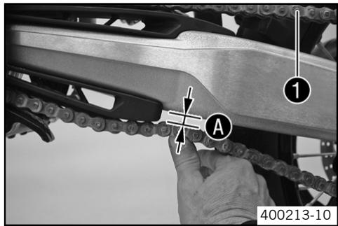
- Jack up the motorcycle. (20)
- Push the chain at the end of the chain sliding component upwards to measure the chain tension A .

Info
The upper chain section 1 must be taut.
Chain wear is not always even, so you should repeat this measurement at different chain positions.
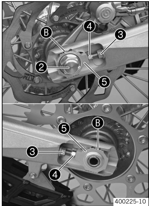
- Loosen nut ②.
- Loosen nuts ③.
- Adjust the chain tension by turning the adjusting screws ④ left and right. Rules
| Chain tension | 8...10 mm (0.31...0.39 in) |
| Turn the adjusting screws ④ left and right so that the markings on the left and right chain adjusters are in the same position relative to the reference marks ③. The rear wheel is then correctly aligned. | |
- Tighten nuts ③.
- Make sure that the chain adjusters ⑤ are fitted correctly on the adjusting screws ④.
- Tighten nut ②. Rules
| Nut, rear wheel spindle | M20x1,5 | 80 Nm (59.01 lbf ft) |

Info
The wide adjustment range of the chain adjusters (32 mm) enables different secondary transmissions with the same chain length.
The chain adjusters ⑤ can be turned by 180^ .
- Remove the motorcycle from the work stand. (20)
Adjusting chain tension - after checking
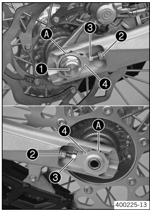
- Loosen nut 1.
- Loosen nuts ②.
- Adjust the chain tension by turning the adjusting screws ③ left and right. Rules
| Chain tension | 8...10 mm (0.31...0.39 in) |
| Turn the adjusting screws ③ left and right so that the markings on the left and right chain adjusters are in the same position relative to the reference marks A. The rear wheel is then correctly aligned. | |
- Tighten nuts ②.
- Make sure that the chain adjusters 4 are fitted correctly on the adjusting screws ③.
- Tighten nut 1. Rules
| Nut, rear wheel spindle | M20x1,5 | 80 Nm (59.01 lbf ft) |

Info
The wide adjustment range of the chain adjusters (32 mm) enables different secondary transmissions with the same chain length. The chain adjusters 4 can be turned by 180^ .
Adjusting chain tension - fitting rear wheel
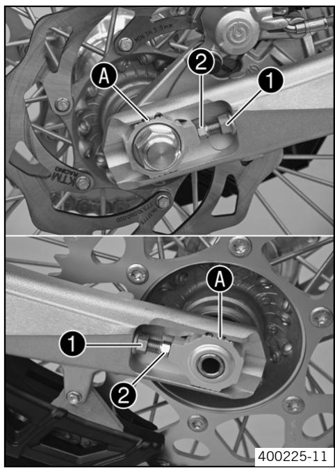
- Loosen nuts 1.
- Adjust the chain tension by turning the adjusting screws ② left and right. Rules
| Chain tension | 8...10 mm (0.31...0.39 in) |
| Turn the adjusting screws ➁ left and right so that the markings on the left and right chain adjusters are in the same position relative to the reference marks ➂. The rear wheel is then correctly aligned. | |
- Tighten nuts ①.
Adjusting chain guide (450 SX-F, 505 SX-F)
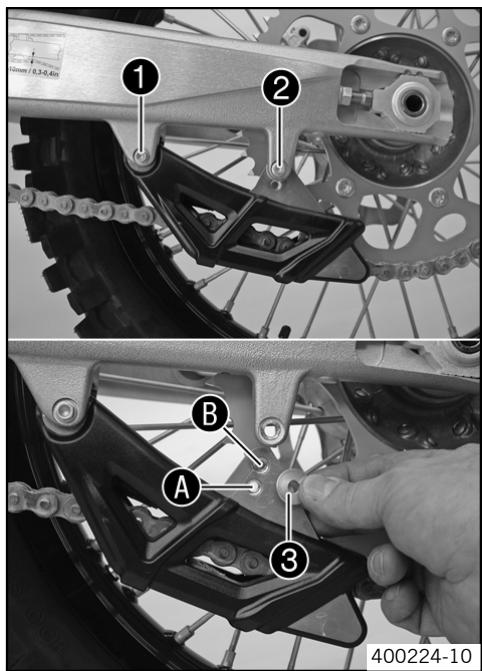
- Loosen screw ①. Remove screw ②. Swing the chain guide downwards.
Conditions
Number of teeth: ≤ 44 teeth
- Insert collar sleeve in hole A. Position the chain guide.
Mount and tighten screw ②. Tighten screw ①.
Rules
| Remaining screws, chas-sis | M6 | 10 Nm (7.38 lbf ft) |
Conditions
Number of teeth: ≥ 45 teeth
- Insert collar sleeve in hole . Position the chain guide.
Mount and tighten screw ②. Tighten screw ①.
Rules
| Remaining screws, chasis | M6 | 10 Nm (7.38 lbf ft) |
Adjusting chain guide (450 XC-F, 505 XC-F)
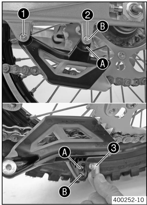
- Remove screws ① and ②. Take off the chain guide.
Conditions
Number of teeth: ≤ 44 teeth
- Insert nut ⑥ in hole A. Position the chain guide.
- Mount and tighten screws ① and ②. Rules
| Remaining screws, chasis | M6 | 10 Nm (7.38 lbf ft) |
Conditions
Number of teeth: ≥ 45 teeth
- Insert nut ③ in hole ③. Position the chain guide.
- Mount and tighten screws ① and ②. Rules
| Remaining screws, chasis | M6 | 10 Nm (7.38 lbf ft) |
Brake fluid reservoir

Warning
Danger of accidents Brake system failure.
- If the brake fluid level falls below the MIN mark, this indicates a leakage in the brake system or worn-out brake linings. Have the brake system checked in an authorized KTM workshop, and do not ride any further.
The brake fluid reservoirs of the front and rear brakes are dimensioned so that they do not need topping up with brake fluid even if the brake linings are worn.
Brake calipers
The brake calipers of this series are "floating", which means that they are not fixed to the brake caliper support. The lateral compensation ensures an optimal position of the brake pad in relation to the brake disc.
Checking brake discs

Warning
Danger of accidents Reduced braking due to worn brake discs.
- Worn brake discs should be replaced immediately in an authorized KTM workshop.
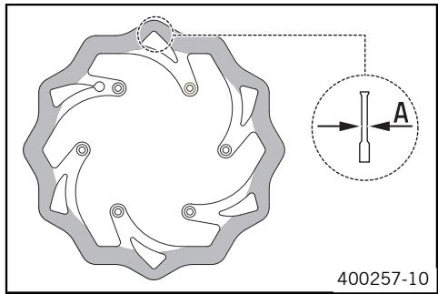
- Check the thickness of the front and rear brake discs at several places on the disc to see if it conforms to measurement A.

Info
Wear reduces the thickness of the brake disc around the area used by the brake linings.
| Wear limit of brake discs | |
| front | 2.5 mm (0.1 in) |
| rear | 3.5 mm (0.14 in) |
If the brake disc thickness is less than the specified value.
- Replace the brake disc.
Checking free play of hand brake lever

Warning
Danger of accidents Brake system failure.
- If there is no free travel on the hand brake lever, pressure builds up on the front brake in the brake system. The front brake can fail due to overheating. Adjust free travel on hand brake lever according to specifications.
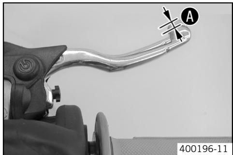
Push the hand brake lever forwards and check free play. A.
Free play of hand brake lever ≥3 mm (≥0.12 in)
If the free travel does not meet specifications:
- adjust the basic position of handbrake lever. (39)
Adjusting basic position of handbrake lever
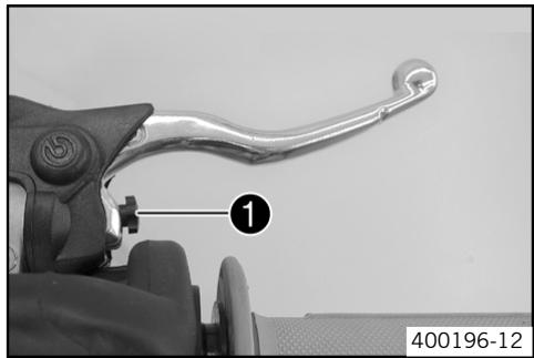
- Adjust the basic setting of the handbrake lever to your hand size by turning adjusting screw .

Info
Turn the adjusting screw clockwise to increase the distance between the handbrake lever and the handlebar.
Turn the adjusting screw counterclockwise to decrease the distance between the handbrake lever and the handlebar.
The range of adjustment is limited.
Turn the adjusting screw by hand only, and do not apply any force.
Do not make any adjustments while riding!
- Check the free play of the hand brake lever. (39)
Checking front brake fluid level

Warning
Danger of accidents Brake system failure.
- If the brake fluid level falls below the MIN mark, this indicates a leakage in the brake system or worn-out brake linings. Have the brake system checked in an authorized KTM workshop, and do not ride any further.

Warning
Danger of accidents Reduced braking due to old brake fluid.
- Have the front and rear brake fluid replaced according to the service plan in an authorized KTM workshop.
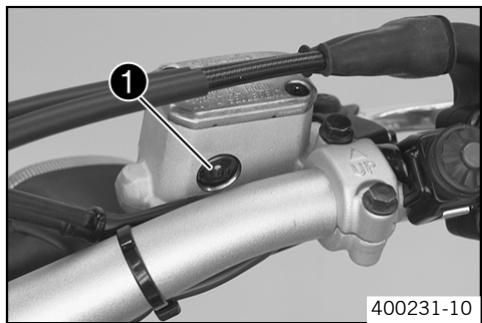
- Move the brake fluid reservoir mounted on the handlebar to a horizontal position.
- Check the brake fluid level in the viewer ①.
If the brake fluid is below MIN the mark:
Top up the brake fluid of the front brake. (40)
Topping up the front brake fluid

Warning
Danger of accidents Brake system failure.
- If the brake fluid level falls below the MIN mark, this indicates a leakage in the brake system or worn-out brake linings. Have the brake system checked in an authorized KTM workshop, and do not ride any further.

Warning
Skin irritations Brake fluid can cause skin irritation on contact.
- Avoid contact with skin and eyes, and keep out of the reach of children.
If brake fluid gets into your eyes, rinse thoroughly with water and contact a doctor immediately.

Warning
Danger of accidents Reduced braking due to old brake fluid.
- Have the front and rear brake fluid replaced according to the service plan in an authorized KTM workshop.

Warning
Environmental hazard Problem materials cause environmental damage.
- Dispos of oil, grease, filters, fuel, cleaning substances, brake fluid, batteries, etc. according to regulations.

Info
KTM recommends DOT 5.1 brake fluid from Motorex®. This has a higher wet boiling point than DOT 4 brake fluid and provides greater safety for high demands.
Never user DOT 5 brake fluid! This is based on silicone oil and is colored purple. Oil seals and brake lines are not designed for DOT 5 brake fluid.
Avoid contact between brake fluid and painted parts. Brake fluid attacks paint!
Use only clean brake fluid from a sealed container!
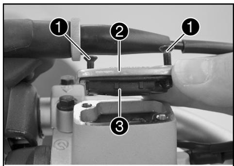
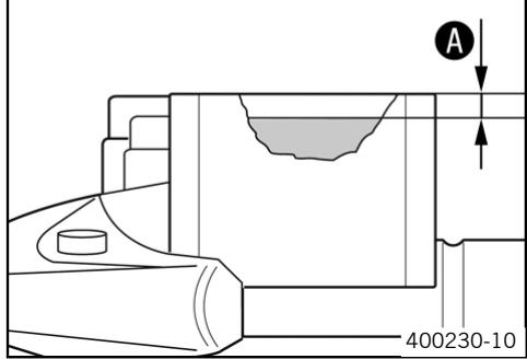
- Move the brake fluid reservoir mounted on the handlebar to a horizontal position.
- Remove screws 1.
- Remove the cover ② with membrane ③.
Top up brake fluid to level A.
Rules
Conditions
Measurement of A:
5 mm (0.2 in)
Brake fluid DOT 5.1 (82)
- Check parts for damage and wear. Replace damaged or worn parts.
- Replace membrane ③, lid ② and screws ①.
- Clean up overflowed or spilt brake fluid immediately with water.
Checking the front brake linings

Warning
Danger of accidents Reduced braking due to worn brake linings.
- Worn brake linings should be replaced immediately in an authorized KTM workshop.
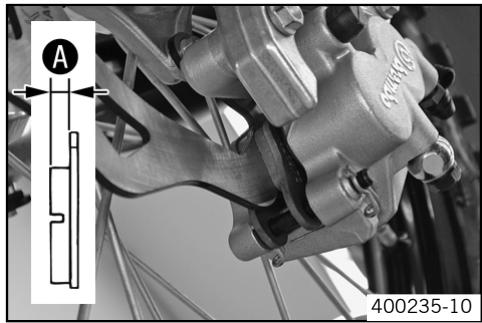
- Check the brake linings for thickness A .
Lining thickness A : ≤ 1 mm ( ≤ 0.04 in)
The lining thickness is less than the specified measurement:
- Change the front brake linings. (42)
Removing front brake linings

Warning
Danger of accidents Improper brake maintenance and repair.
- Always have your brake system maintained and repaired in an authorized KTM workshop.
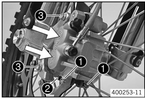
- Press the brake caliper by hand on to the brake disc in order to press back the brake pistons.

Info
Make sure when pushing back the brake pistons that you do not press the brake caliper against the spokes.
- Remove the locking split pins ①, withdraw the bolt ②, and take out the brake pads.
- Remove screws ③ and take off brake caliper.
- Clean brake caliper and brake caliper support.
Mounting front brake linings

Warning
Danger of accidents Reduced braking due to oil or grease on the brake discs.
Always keep the brake discs free of oil and grease, and clean them with brake cleaner when necessary.

Warning
Danger of accidents Reduced braking due to use of non-approved brake linings.
- Brake linings available from accessory suppliers are often not tested and approved for use on KTM motorcycles. The construction and friction factor of the brake linings and therefore the brake power can differ considerably from the original KTM brake linings. If brake linings are used that differ from the originals, there is no guarantee that they comply with the original license. The motorcycle no longer corresponds to the condition at delivery, and the warranty is no longer valid.
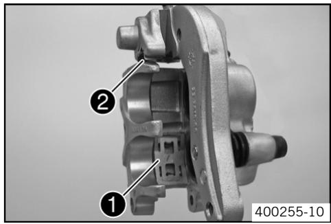
- Check the brake discs. (38)
- Check parts for damage and wear. Replace damaged or worn parts.
- Check that the leaf spring 1 in the brake caliper and sliding plate 2 in the brake caliper support are seated correctly.

Info
The arrow on the leaf spring points in the rotation direction of the brake disc.
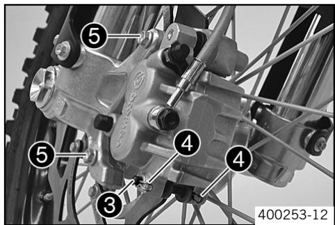
- Fit brake pads, insert bolt ③, and fit locking split pins ④.
- Position brake caliper, mount and tighten screws ⑤ . Rules
| Screw, front brake caliper | M8 | 25 Nm (18.44 lbf ft) | Loctite® 243TM (€ 84) |
- Operate the hand brake lever repeatedly until the brake linings lie on the brake disc and there is a tight spot.
Changing the fron brake linings

Warning
Skin irritations Brake fluid can cause skin irritation on contact.
- Avoid contact with skin and eyes, and keep out of the reach of children.
If brake fluid gets into your eyes, rinse thoroughly with water and contact a doctor immediately.

Warning
Danger of accidents Reduced braking due to old brake fluid.
- Have the front and rear brake fluid replaced according to the service plan in an authorized KTM workshop.

Warning
Environmental hazard Problem materials cause environmental damage.
- Dispose of oil, grease, filters, fuel, cleaning substances, brake fluid, batteries, etc. according to regulations.

Info
KTM recommends DOT 5.1 brake fluid from Motorex®. This has a higher wet boiling point than DOT 4 brake fluid and provides greater safety for high demands.
Never user DOT 5 brake fluid! This is based on silicone oil and is colored purple. Oil seals and brake lines are not designed for DOT 5 brake fluid.
Avoid contact between brake fluid and painted parts. Brake fluid attacks paint!
Use only clean brake fluid from a sealed container!
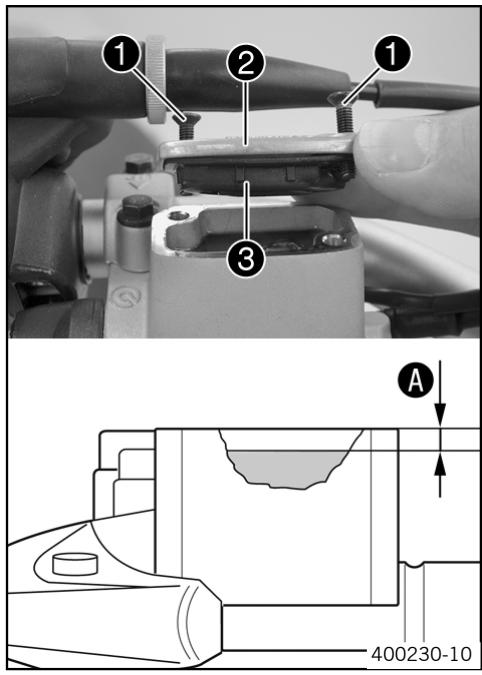
- Remove the front brake linings. (41)
- Move the brake fluid reservoir mounted on the handlebar to a horizontal position.
- Remove screws 1.
- Remove the cover ② with membrane ③.
- Press the brake piston back to its basic position and make sure that no brake fluid overflows from the reservoir.
Mount the front brake linings. (41) - Top up brake fluid to level A. Rules
Conditions
| Measurement of A: | 5 mm (0.2 in) |
Brake fluid DOT 5.1 (82)
- Check parts for damage and wear. Replace damaged or worn parts.
- Replace membrane ③, lid ② and screws ①.
- Clean up overflowed or spilt brake fluid immediately with water.
Checking free play of foot brake lever

Warning
Danger of accidents Brake system failure.
If there is no free travel on the foot brake pedal, pressure builds up on the rear brake in the brake system. The rear brake can fail due to overheating. Adjust free travel on foot brake pedal according to specifications.
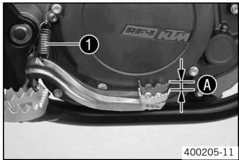
- Disconnect spring ①.
- Move the foot brake lever backwards and forwards between the end stop and the foot brake cylinder piston bracket and check free play . Rules
| Free play at foot brake lever | 3...5 mm (0.12...0.2 in) |
If the free play does not meet specifications:
-
Adjust the basic position of the footbrake lever. (43)
-
Reconnect spring 1.
Adjusting basic position of footbrake lever

Warning
Danger of accidents Brake system failure.
- If there is no free travel on the foot brake pedal, pressure builds up on the rear brake in the brake system. The rear brake can fail due to overheating. Adjust free travel on foot brake pedal according to specifications.
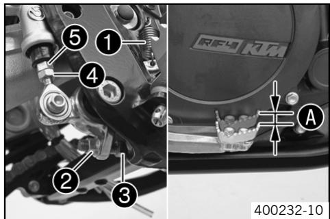
- Disconnect spring 1.
- Loosen nut 4 and with push rod 5, turn it back until you have maximum free play.
- To adjust the basic position of the footbrake lever individually, loosen nut ② and turn screw ③ accordingly.

Info
The range of adjustment is limited.
- Turn push rod ⑤ accordingly until you have free play A. If necessary, adjust the basic position of the footbrake lever. Rules
| Free play at foot brake lever | 3...5 mm (0.12...0.2 in) |
Hold screw ③ and tighten nut ②. Rules
| Remaining nuts, chassis | M8 | 30 Nm (22.13 lbf ft) |
Hold push rod ⑤ and tighten nut ④. Rules
| Remaining nuts, chassis | M6 | 15 Nm (11.06 lbf ft) |
- Reconnect spring 1.
Checking rear brake fluid level

Warning
Danger of accidents Brake system failure.
- If the brake fluid level falls below the MIN mark, this indicates a leakage in the brake system or worn-out brake linings. Have the brake system checked in an authorized KTM workshop, and do not ride any further.

Warning
Danger of accidents Reduced braking due to old brake fluid.
- Have the front and rear brake fluid replaced according to the service plan in an authorized KTM workshop.
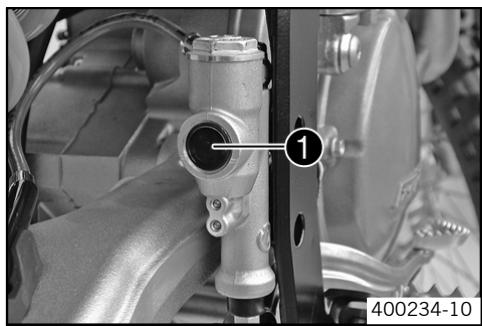
- Stand the vehicle upright.
- Check the brake fluid level in the viewer ①.
When in the viewer 1 an air bubble is visible :
- Top up the brake fluid of the rear brake. (44)
Topping up brake fluid of front brake

Warning
Danger of accidents Brake system failure.
- If the brake fluid level falls below the MIN mark, this indicates a leakage in the brake system or worn-out brake linings. Have the brake system checked in an authorized KTM workshop, and do not ride any further.

Warning
Skin irritations Brake fluid can cause skin irritation on contact.
- Avoid contact with skin and eyes, and keep out of the reach of children.
If brake fluid gets into your eyes, rinse thoroughly with water and contact a doctor immediately.

Warning
Danger of accidents Reduced braking due to old brake fluid.
- Have the front and rear brake fluid replaced according to the service plan in an authorized KTM workshop.

Warning
Environmental hazard Problem materials cause environmental damage.
- Dispose of oil, grease, filters, fuel, cleaning substances, brake fluid, batteries, etc. according to regulations.

Info
KTM recommends DOT 5.1 brake fluid from Motorex®. This has a higher wet boiling point than DOT 4 brake fluid and provides greater safety for high demands.
Never user DOT 5 brake fluid! This is based on silicone oil and is colored purple. Oil seals and brake lines are not designed for DOT 5 brake fluid.
Avoid contact between brake fluid and painted parts. Brake fluid attacks paint!
Use only clean brake fluid from a sealed container!
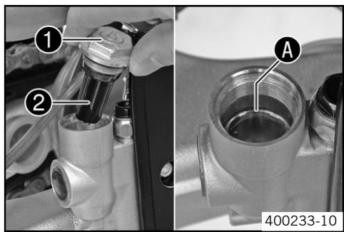
- Stand the vehicle upright.
- Remove screw ① with membrane ②.
- Top up the brake fluid to level A.
Brake fluid DOT 5.1 (82)
- Check parts for damage and wear. Replace damaged or worn parts.
- Refit screw ① with membrane ②.
- Clean up overflowed or spilt brake fluid immediately with water.
Checking rear brake linings

Warning
Danger of accidents Reduced braking due to worn brake linings.
- Worn brake linings should be replaced immediately in an authorized KTM workshop.
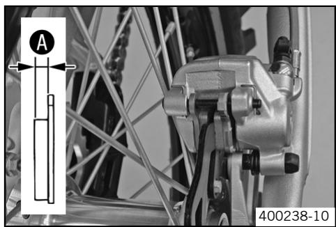
- Check the brake linings for thickness A .
Lining thickness A : ≤ 1 mm ( ≤ 0.04 in)
The lining thickness is less than the specified measurement:
- Change the rear brake linings. (46)
Removing rear brake linings

Warning
Danger of accidents Improper brake maintenance and repair.
- Always have your brake system maintained and repaired in an authorized KTM workshop.
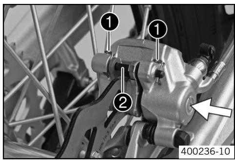
- Press the brake caliper by hand on to the brake disc in order to press back the brake piston.

Info
Make sure when pushing back the brake piston that you do not press the brake caliper against the spokes.
- Remove the locking split pins ①, withdraw the bolt ②, and take out the brake pads.
- Clean brake caliper and brake caliper support.
Mounting rear brake linings

Warning
Danger of accidents Reduced braking due to oil or grease on the brake discs.
Always keep the brake discs free of oil and grease, and clean them with brake cleaner when necessary.

Warning
Danger of accidents Reduced braking due to use of non-approved brake linings.
- Brake linings available from accessory suppliers are often not tested and approved for use on KTM motorcycles. The construction and friction factor of the brake linings and therefore the brake power can differ considerably from the original KTM brake linings. If brake linings are used that differ from the originals, there is no guarantee that they comply with the original license. The motorcycle no longer corresponds to the condition at delivery, and the warranty is no longer valid.
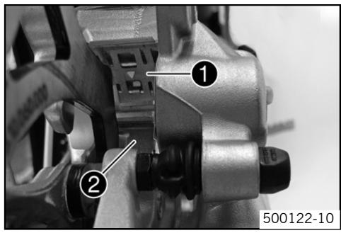
- Check the brake discs. (38)
- Check parts for damage and wear. Replace damaged or worn parts.
- Check that the leaf spring 1 in the brake caliper and sliding plate 2 in the brake caliper support are seated correctly.

Info
The arrow on the leaf spring points in the rotation direction of the brake disc.
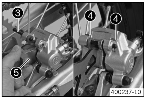
- Fit brake pads, insert bolt ③, and fit locking split pins ④.

Info
Make sure that the decoupling plate ⑤ is mounted on the piston side of the brake pad.
- Operate the foot brake lever repeatedly until the brake linings lie on the brake disc and there is a tight spot.
Changing rear brake linings

Warning
Skin irritations Brake fluid can cause skin irritation on contact.
- Avoid contact with skin and eyes, and keep out of the reach of children.
If brake fluid gets into your eyes, rinse thoroughly with water and contact a doctor immediately.

Warning
Danger of accidents Reduced braking due to old brake fluid.
- Have the front and rear brake fluid replaced according to the service plan in an authorized KTM workshop.

Warning
Environmental hazard Problem materials cause environmental damage.
- Dispos of oil, grease, filters, fuel, cleaning substances, brake fluid, batteries, etc. according to regulations.

Info
KTM recommends DOT 5.1 brake fluid from Motorex®. This has a higher wet boiling point than DOT 4 brake fluid and provides greater safety for high demands.
Never user DOT 5 brake fluid! This is based on silicone oil and is colored purple. Oil seals and brake lines are not designed for DOT 5 brake fluid.
Avoid contact between brake fluid and painted parts. Brake fluid attacks paint!
Use only clean brake fluid from a sealed container!
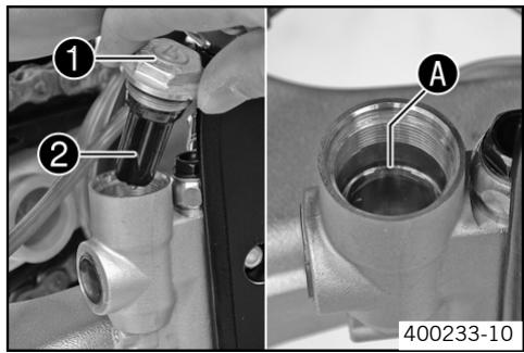
- Remove the rear brake linings. (45)
- Stand the vehicle upright.
- Remove screw ① with membrane ②.
- Press the brake piston back to its basic position and make sure that no brake fluid overflows from the reservoir.
Mount the rear brake linings. (45) - Top up the brake fluid to level A.
Brake fluid DOT 5.1 (82)
- Check parts for damage and wear. Replace damaged or worn parts.
Mount screw 1 with membrane 2. - Clean up overflowed or spilt brake fluid immediately with water.
Removing front wheel
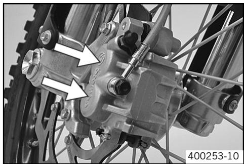
- Jack up the motorcycle. (20)
- Press the brake caliper by hand on to the brake disc in order to press back the brake pistons.

Info
Make sure when pushing back the brake pistons that you do not press the brake caliper against the spokes.
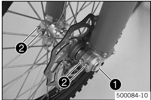
- Remove screw 1.
- Loosen screw ②.
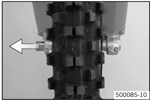
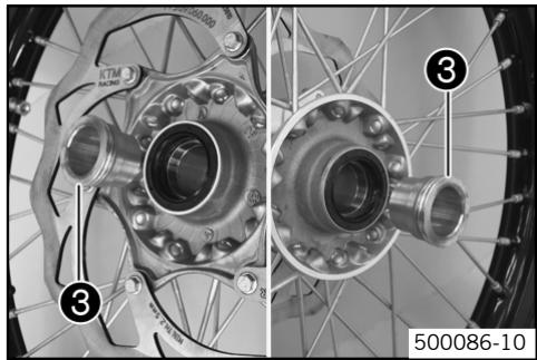
- Holding the front wheel, withdraw the wheel spindle. Take the front wheel out of the fork.

Info
Do not pull the hand brake lever when the front wheel is removed.
Always lay the wheel down in such a way that the brake disc is not damaged.
- Remove distance bushing ③.
Fitting front wheel

Warning
Danger of accidents Reduced braking due to oil or grease on the brake discs.
Always keep the brake discs free of oil and grease, and clean them with brake cleaner when necessary.
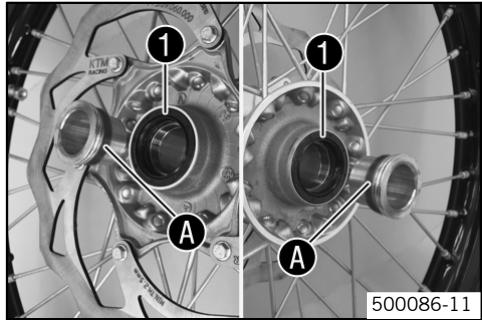
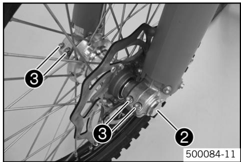
- Check parts for damage and wear. Replace damaged or worn parts.
- Clean and grease shaft seal rings 1 and bearing surface A of the distance bushings.
Long-life grease (84)
-
Fit the distance bushings.
-
Lift the front wheel into the fork, position it, and insert the wheel spindle.
Mount and tighten screw ②.
Rules
| Screw, front wheel spin- dle | M24x1,5 | 40 Nm (29.5 lbf ft) |
- Operate the hand brake lever several times until the brake pads are lying correctly on the brake disc.
- Remove the motorcycle from the work stand. (20)
- Pull the front wheel brake and push down hard on the fork several times to align the fork legs.
- Fully tighten screw ⑥.
Rules
| Screw, fork stub | M8 | 15 Nm (11.06 lbf ft) |
Removing rear wheel
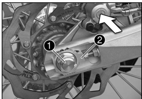
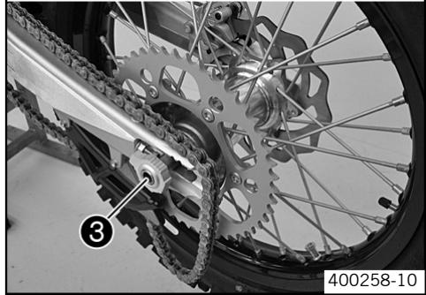
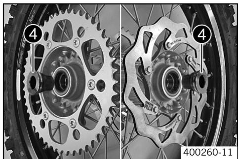
- Jack up the motorcycle. (20)
- Press the brake caliper by hand on to the brake disc in order to press back the brake piston.

Info
Make sure when pushing back the brake piston that you do not press the brake caliper against the spokes.
- Remove nut 1.
- Remove chain adjuster ②. Withdraw the wheel spindle ③ only enough to allow the rear wheel to be pushed forward.
- Push the rear wheel forward as far as possible. Remove the chain from the rear sprocket.
- Holding the rear wheel, withdraw the wheel spindle. Take the rear wheel out of the swing arm.

Info
Do not operate the foot brake when the rear wheel is removed.
Always lay the wheel down in such a way that the brake disc is not damaged.
- Remove distance bushing 4.
Fitting rear wheel

Warning
Danger of accidents Reduced braking due to oil or grease on the brake discs.
Always keep the brake discs free of oil and grease, and clean them with brake cleaner when necessary.
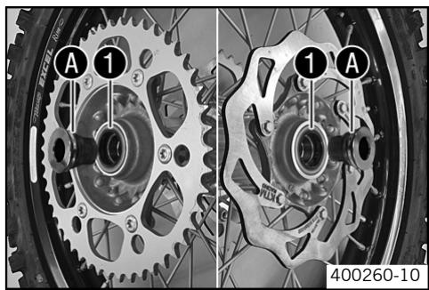
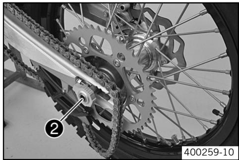
- Check parts for damage and wear. Replace damaged or worn parts.
- Clean and grease shaft seal rings 1 and bearing surface A of the distance bushings.
Long-life grease (84)
-
Fit the distance bushings.
-
Lift the rear wheel into the swing arm, position it, and insert the wheel spindle ②.
Put the chain on.
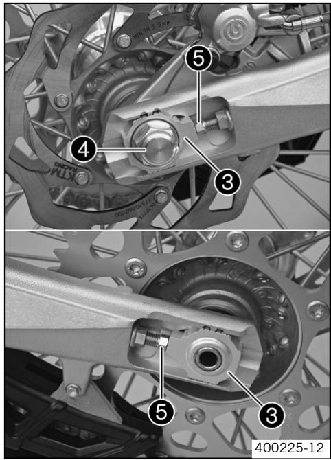
Position the chain adjuster ③. Fit nut ④, but do not tighten it yet.
- Check chain tension when fitting rear wheel. (34)
- Make sure that the chain adjusters ③ are fitted correctly on the adjusting screws ⑤.
- Tighten nut 4.
Rules
| Nut, rear wheel spindle | M20x1,5 | 80 Nm (59.01 lbf ft) |

Info
The wide adjustment range of the chain adjusters (32 mm) enables different secondary transmissions with the same chain length.
The chain adjusters ③ can be turned by 180^
Tire condition checking

Info
Fit only tires approved by KTM.
Other tires could have a negative effect on riding behavior.
The type, condition and air pressure of the tires all have an important impact on the riding behavior of the motorcycle.
The front and rear wheels must be fitted with tires with similar profiles.
Worn tires have a negative effect on riding behavior, especially on wet surfaces.
- Examine the tires for cuts, foreign bodies and other damage.
- Check the depth of the tread.
Depth of tread: ≤ 2mm ( ≤ 0.08 in)
The tread depth is less than the specified measurement:
Replace the tire(s).
Checking tire air pressure

Info
Low tire air pressure leads to abnormal wear and overheating of the tire.
Correct tire air pressure ensures optimal riding comfort and maximum tire service life.
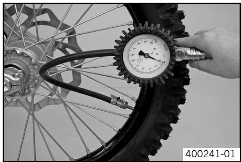
- Remove dust cap.
- Check tire air pressure when tires are cold.
| Tire air pressure off road | |
| front | 1 bar (14.5 psi) |
| rear | 1 bar (14.5 psi) |
If the tire pressure does not meet specifications:
-
Correct tire pressure.
-
Mount dust cap.
Checking spoke tension

Warning
Danger of accidents Unstable riding behavior due to loose spokes.
If you ride with loose spokes, the spokes can break. Have the spoke tension corrected in an authorized KTM workshop.

Info
A loose spoke can cause wheel imbalance, which leads to more loose spokes in a short time.
If the spokes are too tight, they can break due to local overload.
Check the spoke tension regularly, especially on a new motorcycle.
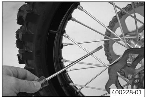
- To check spoke tension, tap each spoke with a screwdriver. Rules
You should hear a high note.
| Spoke nipple, front wheel | M4,5 | 5 Nm (3.69 lbf ft) |
| Spoke nipple, rear wheel | M5 | 5 Nm (3.69 lbf ft) |

Info
If you hear different tone frequencies from different spokes, this is an indication of different spoke tensions.
Removing the battery

Warning
Risk of injury Battery acid and battery gases cause serious cauterization.
- Keep batteries out of the reach of children.
- Wear suitable protective clothing and goggles.
- Avoid contact with battery acid and battery gases.
- Keep the battery away from sparks or open fire. Charge only in well ventilated rooms.
In the event of skin contact, rinse with large amounts of water. If battery acid gets in the eyes, rinse with water for at least 15 minutes and contact a doctor.
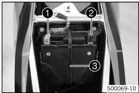
- Switch off all power-consuming components and switch off the engine.
- Remove the seat (53)
- Disconnect the negative (minus) cable 1 of the battery.
- Pull back the plus pole cover ② and disconnect the positive (plus) cable of the battery.
Hang the rubber band ③ out to the bottom. - Lift the battery up.
Installing the battery
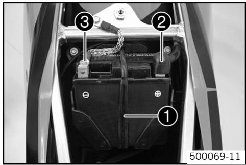
-
Check parts for damage and wear. Replace damaged or worn parts.
-
Place the battery in the battery holder.
450 XC-F, 505 XC-F
4Ah battery (YTX5L-BS) (76)
450 SX-F, 505 SX-F
Conditions
External temperature: ≥ 10^ ( ≥ 50^ )
3Ah battery (YTX4L-BS) (76)
Conditions
External temperature: ≤ 10^ ( ≤ 50^ )
4Ah battery (YTX5L-BS) (76)
- Reconnect the rubber band 1.
- Attach the plus cable and replace the plus pole cover ②.
- Attach the minus cable ③.
Mount the seat (53)
Recharging the battery

Warning
Risk of injury Battery acid and battery gases cause serious cauterization.
- Keep batteries out of the reach of children.
- Wear suitable protective clothing and goggles.
- Avoid contact with battery acid and battery gases.
- Keep the battery away from sparks or open fire. Charge only in well ventilated rooms.
In the event of skin contact, rinse with large amounts of water. If battery acid gets in the eyes, rinse with water for at least 15 minutes and contact a doctor.

Warning
Environmental hazard Components and battery acid are a danger to the environment.
- Do not dispose of batteries in normal household waste. Take defective or used batteries to a battery recycling operator.

Warning
Environmental hazard Problem materials cause environmental damage.
- Dispos of oil, grease, filters, fuel, cleaning substances, brake fluid, batteries, etc. according to regulations.

Info
Even if there is no load on the battery, it loses power every day.
The charge state and the type of charge are very important for the service life of the battery.
Fast recharging with a high charge current shortens the battery's service life.
If the charge current, the charge voltage and the charge time are exceeded, electrolyte escapes through the breathing holes. The battery capacity is then reduced.
If the battery is discharged from starting, it must be recharged immediately.
If it stands for a long time in a discharged state, the battery becomes over-discharged and sulfated, and then it is destroyed.
The battery is maintenance-free, i.e., the acid level does not have to be checked.
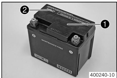
- Switch off all power-consuming components and switch off the engine.
- Remove the seat (53)
- Disconnect the minus (negative) cable of the battery to avoid damage to the motorcycle's electronics.
- Connect the battery charger to the battery. Switch on the battery charger.
Battery charger (58429074000)
You can also use the battery charger to test rest potential and start potential of the battery, and to test the generator. With this device, you cannot overcharge the battery.

Info
Never remove the lid 1.
Charge the battery according to the instructions 2 on the battery casing.
- Switch off the charger after charging. Disconnect the battery. Rules
| The charge current, charge voltage and charge time must not be exceeded. | |
| Charge the battery regularly when the motorcycle is not in use.: | 3 months |
Mount the seat (53)
Removing a fuse
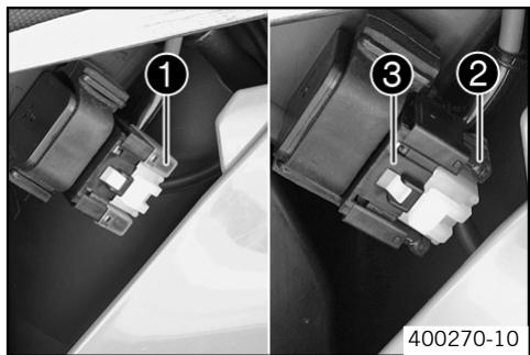
- Switch off all power-consuming components and switch off the engine.
- Dismount the air filter box lid (59)
- Remove the protection cover ①.

Info
The fuse 2 is located in the starter relay 3 under the filter box cover.
- Remove the fuse ②.
Replacing the fuse

Warning
Fire hazard The electrical system can be overloaded by the use of incorrect fuses.
- Use only fuses with the prescribed amperage. Never by-pass or repair fuses.
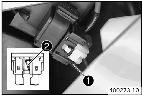
- Check parts for damage and wear. Replace damaged or worn parts.

Info
A reserve fuse 1 is located in the starter relay.
Replace a burned-out fuse 2 only by an equivalent fuse.
Refit the fuse.
Fuse (75011088010)

Info
If the new fuse burns out, contact an authorized KTM workshop.
Replace the protection cover.
Install the air filter box lid (59)
Ignition curve
Possible states
Performance - higher performance
- Soft - better handling
Ignition curve plug connection
Possible states
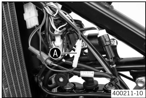
- Plug connection closed
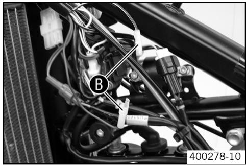
- Plug connection open
Changing ignition curve
- Dismount the fuel tank. (53)
Changing the ignition curve from Performance to Soft. - Open plug connection A. (Figure 400211-10 - 52)
Soft - better handling (52)
Change the ignition curve from Performance to Soft.
- Close plug connection ③. (Figure 400278-10 - 52)
Performance - higher performance (52)
Install the fuel tank. (54)
Removing the seat
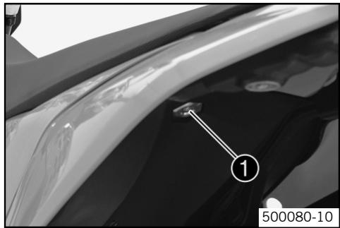
- Remove screw . Lift up the seat at the rear, pull it back and then remove from above.
Mounting the seat
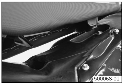
- Check parts for damage and wear. Replace damaged or worn parts.
- Hook in the seat at the front at the flange adaptor from the fuel tank, lower to the rear and simultaneously push forwards.
- Make sure that the seat is correctly locked in.
- Mount and tighten the screw of the seat fixing. Rules
| Remaining screws, chasis | M6 | 10 Nm (7.38 lbf ft) |
Dismounting the fuel tank
- Remove the seat (53)
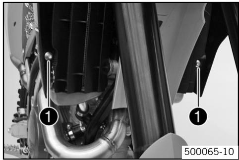

Danger
Fire hazard Fuel can easily catch fire.
- Never fill up the motorcycle near open flames or burning cigarettes, and always switch off the engine first. Be careful that no fuel is spilt, especially on hot motorcycle components. Clean up spilt fuel immediately.
- Fuel in the fuel tank expands when warm and can escape if the tank is overfilled. See specifications on filling up with fuel.

Warning
Danger of poisoning Fuel is poisonous and a health hazard.
- Avoid contact between fuel and skin, eyes and clothing. Do not inhale fuel vapors. If fuel gets into your eyes, rinse immediately with water and contact a doctor. Wash affected skin areas immediately with soap and water. If fuel is swallowed, contact a doctor immediately. Change clothing that has come into contact with fuel. Store fuel in a suitable canister according to regulations and keep it out of the reach of children.
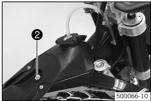
- Close the fuel tap and remove the fuel hose.
- Remove screws ① with collar sleeve.
- Remove screw ② with collar sleeve.
- Remove the tube from the fuel tank vent line.
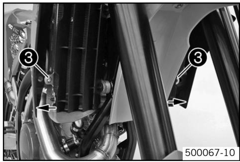
- Pull both spoilers to the side of the radiator bracket ③ and take the fuel tank away upwards.
Installing the fuel tank
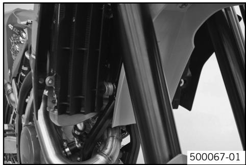

Danger
Fire hazard Fuel can easily catch fire.
- Never fill up the motorcycle near open flames or burning cigarettes, and always switch off the engine first. Be careful that no fuel is spilt, especially on hot motorcycle components. Clean up spilt fuel immediately.
- Fuel in the fuel tank expands when warm and can escape if the tank is overfilled. See specifications on filling up with fuel.

Warning
Danger of poisoning Fuel is poisonous and a health hazard.
-
Avoid contact between fuel and skin, eyes and clothing. Do not inhale fuel vapors. If fuel gets into your eyes, rinse immediately with water and contact a doctor. Wash affected skin areas immediately with soap and water. If fuel is swallowed, contact a doctor immediately. Change clothing that has come into contact with fuel.
-
Check parts for damage and wear. Replace damaged or worn parts.
Position the fuel tank and fit the two spoilers to the side of the radiator fixing. - Make sure that no cables or Bowden cables are trapped or damaged.
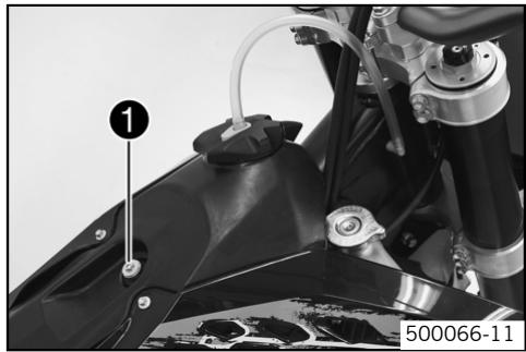
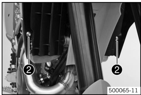
Mount the fuel tank vent hose.
- Fit and tighten screw with collar sleeve. Rules
| Remaining screws, chasis | M6 | 10 Nm (7.38 lbf ft) |
- Fit and tighten screw ② with collar sleeve. Rules
| Remaining screws, chasis | M6 | 10 Nm (7.38 lbf ft) |
- Connect fuel hose.
Mount the seat (53)
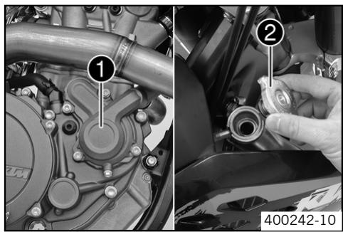
Cooling system
The water pump 1 in the engine forces the coolant to flow.
The pressure resulting from the warming of the cooling system is regulated by a valve in the radiator cap ②. The specified coolant temperature is therefore permissible without danger of function problems.
120°C (248°F)
Coolant (82)
Cooling is effected by the air stream.
The lower the speed, the less the cooling effect. Dirty cooling fins also reduce the cooling effect.
Checking antifreeze and coolant level

Warning
Danger of scalding The coolant gets very hot when the motorcycle is driven and is under high pressure.
- Do not open the radiator, radiator hoses or other cooling system components when the engine is hot. Allow the engine and cooling system to cool down. If you scald yourself, hold the affected area under cold water immediately.

Warning
Danger of poisoning Coolants are poisonous and a health hazard.
- Avoid contact between coolants and skin, eyes and clothing. If fuel gets into your eyes, rinse immediately with water and contact a doctor. Wash affected skin areas immediately with soap and water. If coolant is swallowed, contact a doctor immediately. Change clothes that have come into contact with coolants. Keep coolants out of the reach of children.
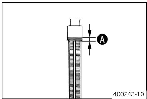
- Stand the vehicle upright.
- Remove the radiator cap.
- Check antifreeze of coolant.
-25...45°C (-13...-49°F)
If the antifreeze of the cooling liquid does not meet specifications:
-
Correct antifreeze of coolant.
-
Check the coolant level in the radiator.
Coolant level A above radiator fins.: 10 mm (0.39 in)
If the level of the cooling liquid does not meet specifications:
- Correct the coolant level.
Alternative 1
Coolant (82)
Alternative 2
Coolant (mixed ready to use) (82)
- Refit the radiator cap.
Checking the coolant level

Warning
Danger of scalding The coolant gets very hot when the motorcycle is driven and is under high pressure.
- Do not open the radiator, radiator hoses or other cooling system components when the engine is hot. Allow the engine and cooling system to cool down. If you scald yourself, hold the affected area under cold water immediately.

Warning
Danger of poisoning Coolants are poisonous and a health hazard.
- Avoid contact between coolants and skin, eyes and clothing. If fuel gets into your eyes, rinse immediately with water and contact a doctor. Wash affected skin areas immediately with soap and water. If coolant is swallowed, contact a doctor immediately. Change clothes that have come into contact with coolants. Keep coolants out of the reach of children.
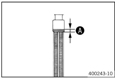
- Stand the vehicle upright.
- Remove the radiator cap.
- Check the coolant level in the radiator.
Coolant level A above radiator fins.: 10 mm (0.39 in)
If the level of the cooling liquid does not meet specifications:
- Correct the coolant level.
Alternative 1
Coolant (82)
Alternative 2
Coolant (mixed ready to use) (82)
- Refit the radiator cap.
Draining coolant

Warning
Danger of scalding The coolant gets very hot when the motorcycle is driven and is under high pressure.
- Do not open the radiator, radiator hoses or other cooling system components when the engine is hot. Allow the engine and cooling system to cool down. If you scald yourself, hold the affected area under cold water immediately.

Warning
Danger of poisoning Coolants are poisonous and a health hazard.
- Avoid contact between coolants and skin, eyes and clothing. If fuel gets into your eyes, rinse immediately with water and contact a doctor. Wash affected skin areas immediately with soap and water. If coolant is swallowed, contact a doctor immediately. Change clothes that have come into contact with coolants. Keep coolants out of the reach of children.

- Stand the vehicle upright.
- Place a suitable container under the water pump cover.
- Remove screw ①. Remove the radiator cap ②.
- Completely drain the coolant.
- Fit screw ① with a new seal and tighten it. Rules
Screw, water pump cover M6 10 Nm (7.38 lbf ft)
Refilling coolant

Warning
Danger of poisoning Coolants are poisonous and a health hazard.
- Avoid contact between coolants and skin, eyes and clothing. If fuel gets into your eyes, rinse immediately with water and contact a doctor. Wash affected skin areas immediately with soap and water. If coolant is swallowed, contact a doctor immediately. Change clothes that have come into contact with coolants. Keep coolants out of the reach of children.
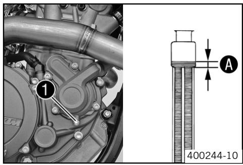
- Make sure that the screw ① is tightened.
- Stand the vehicle upright.
- Pour coolant in up to measurement A above the radiator fins. Rules
| 10 mm (0.39 in) | ||
| Coolant | 1.2 l (1.27 qt.) | Coolant (♥ 82) |
| Coolant (mixed ready to use) (♥ 82) | ||
- Refit the radiator cap.
Make a short test ride. - Check the coolant level. (56)
Removing main silencer

Warning
Danger of burns The exhaust system gets very hot when the motorcycle is driven.
- Allow the exhaust system to cool down. Do not touch hot components.
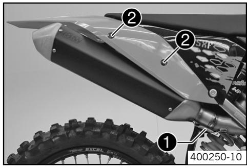
- Disconnect spring 1.
- Remove screws ② and take off main silencer.
Fitting the main silencer
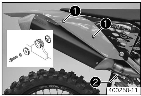
- Check parts for damage and wear. Replace damaged or worn parts.
- Mount the main silencer. Mount and tighten screws ①. Rules
| Remaining screws, chasis | M6 | 10 Nm (7.38 lbf ft) |
- Reconnect spring ②.
Glass fiber yarn filling of main silencer
The main silencer is filled with glass fiber yarn.
Over a period, the fibers of the insulating material vanish into the air, and the silencer "burns out".
Not only is the noise level higher, the performance characteristic changes.
Removing glass fiber yarn filling from the main silencer

Warning
Danger of burns The exhaust system gets very hot when the motorcycle is driven.
- Allow the exhaust system to cool down. Do not touch hot components.
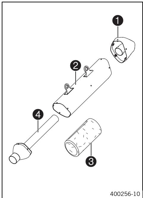
- Remove the main silencer. (57)
- Remove screws of end cap ①. Remove end cap and external tube ②.
- Withdraw glass fiber yarn filling ③ from inner pipe ④ .
Clean the parts you want to use again.
Fitting glass fiber yarn filling in main silencer
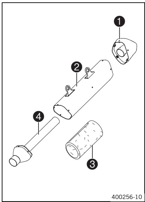
- Check parts for damage and wear. Replace damaged or worn parts.
- Push the glass fiber yarn filling over the inner pipe.
Push the outer pipe over the glass fiber yarn filling. - Insert the end cap in the outer tube. Fit and tighten all screws.
- Fit the main silencer. (57)
Changing glass fiber yarn filling of main silencer
- Remove glass fiber yarn filling from main silencer. (58)
- Fit glass fiber yarn filling in main silencer. (58)
Dismounting the air filter box lid
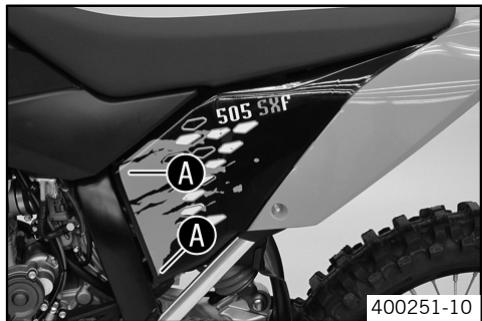
Pull off the air filter box lid in area A to the side and remove to the front.
Installing the air filter box lid
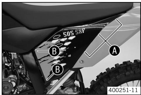
- Insert the air filter box lid into the rear area 4 and clip it into the front area 8.
Removing the air filter
Note
Engine failure Unfiltered intake air has a negative effect on the service life of the engine.
- Never ride the motorcycle without an air filter since dust and dirt can get into the engine and result in increased wear.

Warning
Environmental hazard Problem materials cause environmental damage.
- Dispose of oil, grease, filters, fuel, cleaning substances, brake fluid, batteries, etc. according to regulations.
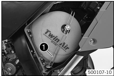
- Dismount the air filter box lid (59)
- Hang the air filter holder out to the bottom and swing it to the side. Remove the air filter with the air filter support.
- Remove the air filter from the air filter support.
Installing the air filter
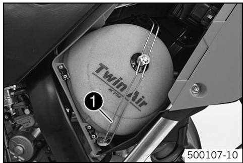
- Check parts for damage and wear. Replace damaged or worn parts.
Mount the clean air filter onto the air filter support.
Put in both parts together, position them and fix them with the air filter support 1.

Info
If the air filter is not correctly mounted, dust and dirt can penetrate into the engine and can cause damage.
Install the air filter box lid (59)
Cleaning air filter

Warning
Environmental hazard Problem materials cause environmental damage.
- Dispose of oil, grease, filters, fuel, cleaning substances, brake fluid, batteries, etc. according to regulations.

Info
Do not clean the air filter with fuel or petroleum since these substances attack the foam.
- Remove the air filter. (59)
- Wash the air filter thoroughly in special cleaning liquid and allow it to dry properly.
Cleaning substance for foam air filter (84)

Info
Only press the air filter to dry it, never wring it out.
Oil the dry air filter with a high/quality filter oil.
Oil for foam air filter (84)
Clean the air filter box.
- Check carburetor connection boot for damage and tightness.
Install the air filter (60)
Adjusting basic position of clutch lever
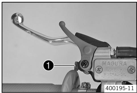
- Adjust the basic setting of the clutch lever to your hand size by turning adjusting screw ①.

Info
Turn the adjusting screw clockwise to increase the distance between the clutch lever and the handlebar.
Turn the adjusting screw counterclockwise to decrease the distance between the clutch lever and the handlebar.
The range of adjustment is limited.
Turn the adjusting screw by hand only, and do not apply any force.
Do not make any adjustments while riding!
Checking fluid level of hydraulic clutch

Info
The fluid level rises with increasing wear of the clutch lining disc.
Do not use brake fluid.
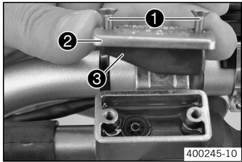
- Move the clutch fluid reservoir mounted on the handlebar to a horizontal position.
- Remove screws 1.
- Remove the cover ② with membrane ③.
- Check the fluid level.
Fluid level under top level of container.: 4 mm (0.16 in)
The fluid level does not comply with specifications.
- Correct the fluid level of the hydraulic clutch.
Hydraulic fluid (82)
- Check parts for damage and wear. Replace damaged or worn parts.
- Replace membrane ③, lid ② and screws ①.
Changing fluid level of hydraulic clutch

Warning
Environmental hazard Problem materials cause environmental damage.
- Dispos of oil, grease, filters, fuel, cleaning substances, brake fluid, batteries, etc. according to regulations.
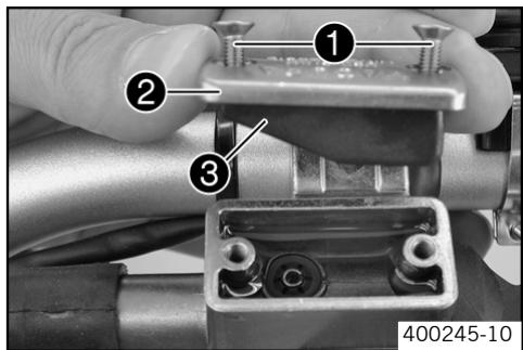
- Move the clutch fluid reservoir mounted on the handlebar to a horizontal position.
- Remove screws 1.
- Remove the cover ② with membrane ③.
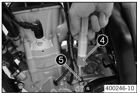
- Fill the bleeding syringe ④ with the appropriate hydraulic fluid.
Bleed syringe (50329050000)
Hydraulic fluid (82)
- On the slave cylinder, remove the bleeder screw ⑤ and fit the bleeding syringe ④.
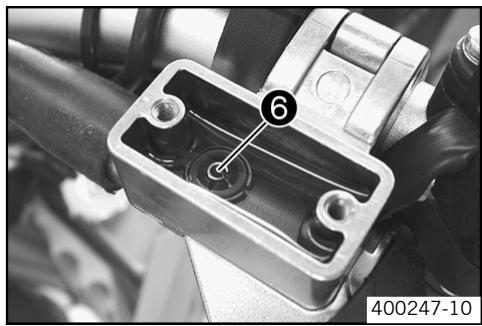
- Inject the liquid into the system until it escapes from the bore hole ⑥ of the master cylinder without bubbles.
- To prevent overflow, drain fluid occasionally from the master cylinder reservoir.
- Remove the bleeding syringe. Mount and tighten screws bleeder screw.
- Correct the fluid level of the hydraulic clutch.
Rules
Fluid level under top level of container.: 4 mm (0.16 in)
- Check parts for damage and wear. Replace damaged or worn parts.
- Replace membrane, lid and screws.
Carburetor - idle
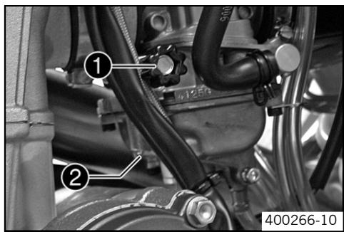
The idle setting of the carburetor has a big influence on the starting behavior, stable idling and the response to throttle opening. That means that an engine with a correctly set idle speed is easier to start than if the idle is set wrongly.

Info
The carburetor and its components are subject to increased wear caused by engine vibration. Wear can result in malfunctioning.
The idle speed is adjusted with the adjustmenr screw 1.
The idle mixture is adjusted with the idle mixture adjustmenr screw ②.
Carburetor - adjusting idle
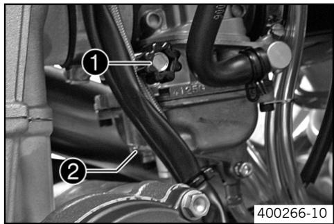
- Screw in the idle adjusting screw ② until it stops and then to the prescribed basic setting.
Rules
| Idle mixture adjusting screw | |
| Open | 1.5 turns |
Adjustment tool for mixture control screw (77329034000)
Run the engine until warm. Rules
| Warm-up time: | ≥ 5 min |
- Adjust the idle speed with the adjusting screw ①. Rules
| Choke function deactivated (← 10) | |
| Idle speed | 1600...1650 rpm |
- Turn the idle adjusting screw ② slowly until the idle speed begins to fall.
- Note the position and turn the idle adjusting screw slowly counterclockwise until the idle speed falls.
- Adjust to the point between these two positions with the highest idle speed.

Info
If there is a big engine speed rise, reduce the idle speed to a normal level and repeat the above steps.
The extreme sport motocycler will set the mixture about 1/4 of a turn back from this ideal value (leaner, in a clockwise direction) since the engine becomes hotter in sporting use.
If the procedure described here does not lead to satisfactory results, the cause may be a wrongly dimensioned idling jet.
If you can turn the idle adjusting screw to the end without any change of engine speed, you have to fit a smaller idling jet.
The idle adjusting screw must not be opened more than two turns. If more than two turns are necessary (rich mixture), use a larger idling jet.
After changing the idling jet, start from the beginning with the adjusting steps.
- Adjust the idle speed with the adjusting screw ①. Rules
| Choke function deactivated (← 10) | |
| Idle speed | 1600...1650 rpm |

Info
Following extreme air temperature or altitude changes, adjust the idle speed again.
Emptying the carburetor float chamber

Danger
Fire hazard Fuel can easily catch fire.
- Never fill up the motorcycle near open flames or burning cigarettes, and always switch off the engine first. Be careful that no fuel is spilt, especially on hot motorcycle components. Clean up spilt fuel immediately.
Fuel in the fuel tank expands when warm and can escape if the tank is overfilled. See specifications on filling up with fuel.

Warning
Danger of poisoning Fuel is poisonous and a health hazard.
- Avoid contact between fuel and skin, eyes and clothing. Do not inhale fuel vapors. If fuel gets into your eyes, rinse immediately with water and contact a doctor. Wash affected skin areas immediately with soap and water. If fuel is swallowed, contact a doctor immediately. Change clothing that has come into contact with fuel. Store fuel in a suitable canister according to regulations and keep it out of the reach of children.

Warning
Environmental hazard Improper handling of fuel is a danger to the environment.
- Do not allow fuel to get into the ground water, the ground, or the sewage system.

Info
Carry out this work with a cold engine.
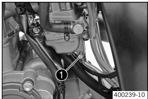
- Turn the handle ① of the fuel tap to the ON position. (Figure 400201-10 - 9)
No more fuel flows from the tank to the carburetor. - Turn the handle ① of the fuel tap to the OFF position. (Figure 400200-10 = 9)
No more fuel flows from the tank to the carburetor. - Guide the hose coming down behind the engine into a suitable container.

Info
Water in the float chamber results in malfunctioning.
- Undo the screw ① (turn it counterclockwise) a few turns and drain the fuel from the float chamber.
- Tighten screw 1.
Checking engine oil level

Info
The engine oil level can be checked on a cold or hot engine.
Conditions
The engine is at operating temperature.
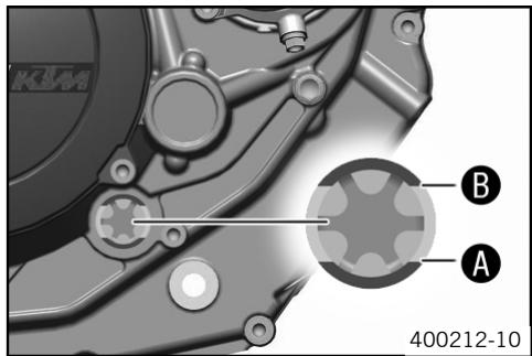
Conditions
Engine is cold.
- Stand the motorcycle upright on a horizontal surface.
- Check the engine oil level.
The engine oil reaches the top of the viewer ⑧.
When the engine oil does not reach the top of the viewer:
- Top up the engine oil. (66)
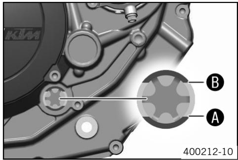
- Check the engine oil level.
The engine oil reaches the bottom of the viewer A.
When the engine oil does not reach the bottom of the viewer:
- Top up the engine oil. (66)
Changing engine oil and oil filter, cleaning oil screen
- Drain the engine oil. (64)
- Remove the oil filter. (65)
Mount the oil filter. (65) - Fill up with engine oil. (66)
Draining the engine oil

Warning
Danger of scalding Engine oil gets very hot when the motorcycle is driven.
- Wear suitable protective clothing and gloves. If you scald yourself, hold the affected area under cold water immediately.

Warning
Environmental hazard Problem materials cause environmental damage.
- Dispos of oil, grease, filters, fuel, cleaning substances, brake fluid, batteries, etc. according to regulations.

Info
Drain the engine oil only when the engine is warm.
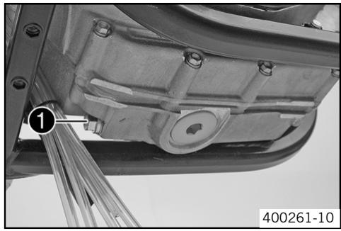
- Stand the motorcycle on its side stand on a horizontal surface.
- Place a suitable container under the engine.
- Remove the oil drain plug ①.
- Completely drain the engine oil.
Thoroughly clean the oil drain plug with a magnet.
Clean the sealing area on the engine. - Check parts for damage and wear. Replace damaged or worn parts.
- Fit oil drain plug ① with seal ring and tighten it. Rules
| Oil drain plug with mag-net | M12x1,5 | 20 Nm (14.75 lbf ft) |
Clean the oil screen. (64)
Cleaning the oil screen

Warning
Danger of scalding Engine oil gets very hot when the motorcycle is driven.
- Wear suitable protective clothing and gloves. If you scald yourself, hold the affected area under cold water immediately.

Warning
Environmental hazard Problem materials cause environmental damage.
-
Dispose of oil, grease, filters, fuel, cleaning substances, brake fluid, batteries, etc. according to regulations.
-
Place a suitable container under the engine.
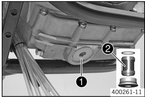
- Loosen the plug with a few light hammer blows.
- Remove plug ① with oil screen ② and O-rings.
- Completely drain the remaining engine oil.
- Thoroughly clean parts and sealing area.
- Check parts for damage and wear. Replace damaged or worn parts.
- Fit and tighten plug ① with oil screen ② and O-rings. Rules
| Plug, oil screen | M32x1,5 | 30 Nm (22.13 lbf ft) |
Removing the oil filter

Warning
Danger of scalding Engine oil gets very hot when the motorcycle is driven.
- Wear suitable protective clothing and gloves. If you scald yourself, hold the affected area under cold water immediately.

Warning
Environmental hazard Problem materials cause environmental damage.
- Dispos of oil, grease, filters, fuel, cleaning substances, brake fluid, batteries, etc. according to regulations.
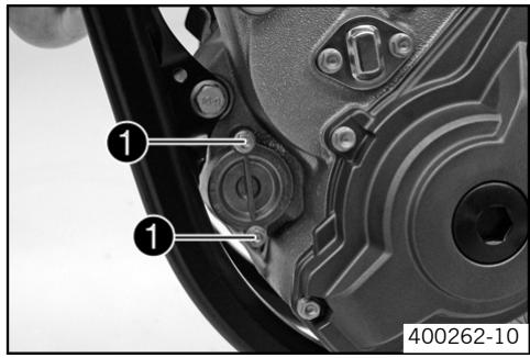
- Place a suitable container under the engine.
- Remove screws ①. Take off the oil filter cover with the O-ring.
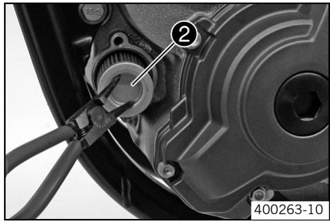
Pull the oil filter insert 2 out of the oil filter casing.
Circlip pliers reverse (51012011000)
- Completely drain the engine oil.
Thoroughly clean parts and sealing area.
Mounting oil filter
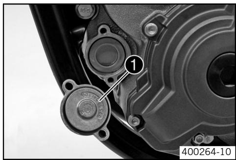
- Check parts for damage and wear. Replace damaged or worn parts.
- Lay the motorcycle on its side and fill the oil filter housing to about 1/3 full with engine oil.
- Fill the oil filter with engine oil and place it in the oil filter container.
Oil the O-ring of the oil filter cover and mount it with the oil filter cover 1. - Mount and tighten screws. Rules
| Screw, oil filter cover | M6 | 10 Nm (7.38 lbf ft) |
- Stand the motorcycle up.
Filling up with engine oil
Info
Too little engine oil or poor-quality engine oil results in premature wear to the engine.
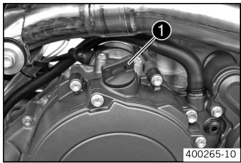
- Remove the screw cap ① on the clutch cover and fill up with engine oil.
Engine oil 1.35 l (1.43 qt.) Engine oil (82)
Mount and tighten screw cap 1.

Danger
Danger of poisoning Exhaust gases are poisonous and can result in unconsciousness or death.
-
When running the engine, always make sure there is sufficient ventilation, and do not start or run the engine in a closed space.
-
Start the engine and check that it is oil-tight.
- Check the engine oil level. (63)
Topping up engine oil

Info
Too little engine oil or poor-quality engine oil results in premature wear to the engine.
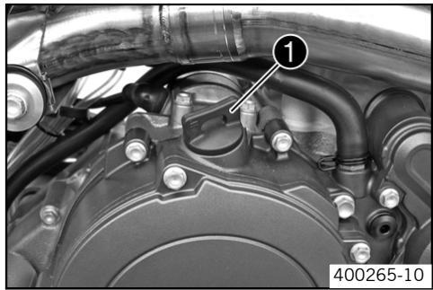
- Remove the screw cap ① on the clutch cover and fill up with engine oil.
Engine oil (82)
Mount and tighten screw cap 1.

Danger
Danger of poisoning Exhaust gases are poisonous and can result in unconsciousness or death.
-
When running the engine, always make sure there is sufficient ventilation, and do not start or run the engine in a closed space.
-
Start the engine and check that it is oil-tight.
| Faults | Possible cause | Measure |
| The engine cannot be crank (electric starter). | Battery discharged | - Recharge the battery. (51) - Check the cause of discharging. |
| Fuse blown | - Remove the fuse. (52) - Replace the fuse. (52) | |
| Low external temperature | - Use the battery supplied in the accessory package. 450 SX-F, 505 SX-F 4Ah battery (YTX5L-BS) (76) | |
| Engine turns but does not start. | Operating error | - Conduct check (14). |
| Motorcycle was out of use for a long time and there is old fuel in the float chamber | - Empty the carburetor float chamber. (63) | |
| Fuel feed interrupted | - Check tank vent. - Clean fuel tap. - Clean carburetor. | |
| Engine flooded | - Clean and dry spark plug or replace if necessary. | |
| Spark plug oily or wet | - Clean and dry spark plug or replace if necessary. | |
| Electrode distance (plug gap) of spark plug too wide | - Adjust plug gap. Rules spark plug electrode gap 0.7 mm (0.03 in) | |
| Spark plug connector or spark plug defective | Warning Risk of injury The ignition system is under high voltage. - Do not touch parts of the ignition system. Have work on the ignition system carried out in an authorized KTM workshop. | |
| - Remove spark plug, connect ignition cable, hold spark plug to ground (bare metal area on engine), and try to start the engine. Rules You should see a strong spark on the spark plug. - If there is no spark, change the spark plug. - If there is still no spark, remove the spark plug cap from the ignition cable, hold it at the specified distance from the ground contact, and try to start the engine. Rules 5 mm (0.2 in) - If you now have a spark, replace the spark plug connector. - If there is no spark, have the ignition system checked. | ||
| Short-circuit cable in wiring harness chafed, short-circuit button defective | - Check wiring harness. (visual check) - Check electrical system. | |
| Socket connector of CDI control device, pulse generator or ignition coil oxidized. | - Clean socket connector and treat it with contact spray. | |
| Water in carburetor or jets blocked | - Clean carburetor. | |
| Engine has no idle. | Idling jet blocked | - Clean carburetor. |
| Adjusting screws on carburetor distorted | - Have the carburetor adjusted. | |
| Spark plug defective | - Change spark plug. | |
| Engine has no idle. | Ignition system defective | - Have ignition system checked. |
| Engine does not speed up. | Carburetor running over because float needle dirty or worn. | - Have carburetor checked. |
| Loose carburetor jets | - Have carburetor checked. | |
| Electronic ignition adjustment defective | - Have ignition system checked. | |
| Engine has too little power. | Fuel feed interrupted | - Check tank vent. - Clean fuel tap. - Clean carburetor. |
| Air filter very dirty | - Clean the air filter. (← 60) | |
| Exhaust system leaky, deformed or too little glass fiber yarn filling in main silencer. | - Check exhaust system for damage. - Change glass fiber yarn filling of main silencer. (← 59) | |
| Valve clearance too little | - Have valve clearance adjusted. | |
| Electronic ignition adjustment defective | - Have ignition system checked. | |
| Engine stalls or is popping into the carburetor. | Lack of fuel | - Clean and check the fuel system and carburetor. |
| Engine takes in bad air | - Check rubber sleeves and carburetor for tightness. | |
| Engine overheats. | Too little coolant in cooling system | - Check the cooling system for leakage. - Check the coolant level. (← 56) |
| Too little air stream | - Switch off engine when standing. | |
| Radiator fins very dirty | - Clean radiator fins. | |
| Foam formation in cooling system | - Drain the coolant. (← 56) - Refill the coolant. (← 57) | |
| Bent radiator hose | - Replace the radiator hose. | |
| High oil consumption | Engine vent hose bent | - Route the vent hose without bends or replace it if necessary. |
| Engine oil level too high | - Check the engine oil level. (← 63) | |
| Engine oil too thin (low viscosity) | - Change the engine oil and oil filter, and clean the oil screen. (← 64) | |
| Battery discharged | Battery is not charged by generator | - Check electrical system. |
Cleaning motorcycle
Note
Material damage Damage and destruction of components by high-pressure cleaning equipment.
- Never clean the motorcycle with high-pressure cleaning equipment or a strong water-jet. The excessive pressure can penetrate electrical components, socket connects, Bowden cables, and bearings, etc., and can damage or destroy these parts.

Warning
Environmental hazard Problem materials cause environmental damage.
- Dispos of oil, grease, filters, fuel, cleaning substances, brake fluid, batteries, etc. according to regulations.

Info
If you clean the motorcycle regularly, its value and appearance are maintained over a long period.
Avoid direct sunshine on the motorcycle during cleaning.
Before you clean the motorcycle, seal the exhaust system to prevent penetration by water.
- First remove coarse dirt particles with a gentle water spray.
Spray very dirty areas with a normal motorcycle cleaner and then clean with a paintbrush.
Motorcycle cleaner (84)

Info
Use warm water containing normal motorcycle cleaner and a soft sponge.
- After rinsing the motorcycle with a gentle water spray, allow it to dry thoroughly.
Empty the carburetor float chamber. (63)

Warning
Danger of accidents Reduced braking due to wet or dirty brakes.
- Clean or dry dirty or wet brakes by riding and braking gently.
After cleaning, ride the vehicle a short distance until the engine warms up, and then apply the brakes.

Info
The heat produced causes water at inaccessible positions in the engine and the brakes to evaporate.
- Push back the protection covers on the handlebar instruments to allow water to evaporate.
- After the motorcycle has cooled off, oil or grease all moving parts and bearings.
Clean the chain. (33)
Treat bare metal parts (except for brake discs and exhaust system) with anti-corrosion materials.
Cleaning and polishing materials for metal, rubber and plastic (84)
Treat all painted parts with a mild paint polish.
High-luster polish for paint (85)
- To prevent electrical problems, treat electric contacts and switches with contact spray.
Contact spray (85)
Storage

Warning
Danger of poisoning Fuel is poisonous and a health hazard.
- Avoid contact between fuel and skin, eyes and clothing. Do not inhale fuel vapors. If fuel gets into your eyes, rinse immediately with water and contact a doctor. Wash affected skin areas immediately with soap and water. If fuel is swallowed, contact a doctor immediately. Change clothing that has come into contact with fuel. Store fuel in a suitable canister according to regulations and keep it out of the reach of children.

Info
If you want to garage the motorcycle for a longer period, take the following actions.

Info
Before storing the motorcycle, check all parts for function and wear. If service, repairs or replacements are necessary, you should do this during the storage period (less workshop overload). In this way, you can avoid long workshop waiting times at the start of the new season.
Clean the motorcycle. (69)
- Change the engine oil and oil filter, and clean the oil screen. (64)
- Check the antifreeze and coolant level. (55)
- Remove the spark plug and fill the cylinder with engine oil. Rules
5cm^3 (0.31 cu in)
- Activate the starter motor to distribute the engine oil over the cylinder wall. Rules
5s
- Replace the spark plug.
- Drain the fuel from the tank into a suitable container.
Empty the carburetor float chamber. (63) - Checking the tire air pressure. (49)
- Remove the battery. (50)
Recharge the battery. (51) Rules
Storage temperature of battery without direct sunshine.:
0...35°C (32...95°F)
- The storage place should be dry and not subject to large temperature differences.
Cover the motorcycle with a porous sheet or blanket. Do not use non-porous materials since they prevent humidity from escaping, thus causing corrosion.

Info
Avoid running the engine for a short time only. Since the engine cannot warm up properly, the water vapor produced during combustion condenses and causes valves and exhaust system to rust.
| Design | 1-cyliner 4-stroke engine, water-cooled |
| Displacement (450 SX-F, 450 XC-F) | 449.3 cm³ (27.42 cu in) |
| Displacement (505 SX-F, 505 XC-F) | 477.5 cm³ (29.14 cu in) |
| Stroke | 60.8 mm (2.39 in) |
| Bore (450 SX-F, 450 XC-F) | 97 mm (3.82 in) |
| Bore (505 SX-F, 505 XC-F) | 100 mm (3.94 in) |
| Compression ratio | 12,5:1 |
| Idle speed | 1600...1650 rpm |
| Control | 4 valves controlled by cam levers ad 2 camshafts, driven by helical gear pair and tooth-wheel chain |
| Valve diameter, intake | 40.4 mm (1.59 in) |
| Valve diameter, exhaust | 31.7 mm (1.25 in) |
| Valve clearance, cold, intake | 0.07...0.13 mm (0...0.01 in) |
| Valve clearance, cold, exhaust | 0.12...0.18 mm (0...0.01 in) |
| Crankshaft bearing | 2 cylinder roller bearing |
| Conrod bearing | Needle bearing |
| Piston pin bearing (450 SX-F, 450 XC-F) | Bronze bush |
| Piston pin bearing (505 SX-F, 505 XC-F) | not a bearing bush - DLC-plated piston pins |
| Pistons | Forged light alloy |
| Piston rings | 1 compression ring, 1 oil scraper ring |
| Engine lubrication | Pressure circulation lubrication with 3 rotor pumps |
| Primary transmission | 29:74 |
| Transmission ratio | |
| Transmission ratio (450 SX-F, 505 SX-F) | |
| 1st gear | 17:32 |
| 2nd gear | 19:30 |
| 3rd gear | 21:28 |
| 4th gear | 23:26 |
| Transmission ratio (450 XC-F, 505 XC-F) | |
| 1st gear | 16:34 |
| 2nd gear | 19:31 |
| 3rd gear | 20:26 |
| 4th gear | 23:25 |
| 5th gear | 26:24 |
| Generator performance | |
| 6000 rpm | 42 W |
| Ignition | Contactless controlled fully electronic ignition with digital ignition adjustment, type Kokusan |
| Spark plug | NGK CR 9 EKB |
| spark plug electrode gap | 0.7 mm (0.03 in) |
| Cooling | Water cooling, permanent circulation of coolant by water pump |
| Starting aid | Electric starter |
Capacity- engine oil
Engine oil
1.35 | (1.43 qt.)
Engine oil (82)
Capacity- cooling liquid
Coolant
1.2 | (1.27 qt.)
Coolant (82)
Coolant (mixed ready to use) (82)
| Engine housing vent jet | M4 | Loctite® 243TM (▼ 84) | |
| Oil jet, piston cooling | M4 | 4 Nm (2.95 lbf ft) | Loctite® 243TM (▼ 84) |
| Oil jet, cam lever lubrication | M4 | 6 Nm (4.43 lbf ft) | Loctite® 243TM (▼ 84) |
| Oil jet, clutch oil supply | M5x1 | 6 Nm (4.43 lbf ft) | Loctite® 243TM (▼ 84) |
| Screw, locking lever | M5 | 6 Nm (4.43 lbf ft) | Loctite® 243TM (▼ 84) |
| Screw, camshaft bearing re-taining bracket | M5 | 6 Nm (4.43 lbf ft) | Loctite® 243TM (▼ 84) |
| Screw, timing train axle retaining bracket | M5 | 6 Nm (4.43 lbf ft) | Loctite® 243TM (▼ 84) |
| Screw, ignition pulse generator | M5 | 6 Nm (4.43 lbf ft) | Loctite® 243TM (▼ 84) |
| Screw, ignition pulse generator adapter | M5 | 6 Nm (4.43 lbf ft) | Loctite® 243TM (▼ 84) |
| Screw, stator cable holder | M5 | 6 Nm (4.43 lbf ft) | Loctite® 243TM (▼ 84) |
| Screw, bearing bolt of oil pump idler shaft | M5 | 6 Nm (4.43 lbf ft) | Loctite® 243TM (▼ 84) |
| Locking screw for bearing | M5 | 6 Nm (4.43 lbf ft) | Loctite® 243TM (▼ 84) |
| Screw, oil pump cover | M5 | 6 Nm (4.43 lbf ft) | Loctite® 243TM (▼ 84) |
| Screw, stator bracket | M5 | 6 Nm (4.43 lbf ft) | Loctite® 243TM (▼ 84) |
| Oil jet, timing chain tensioner | M6x0,6 | 6 Nm (4.43 lbf ft) | Loctite® 243TM (▼ 84) |
| Nut, water-pump wheel | M6 | 6 Nm (4.43 lbf ft) | Loctite® 243TM (▼ 84) |
| Nut, cylinder head | M6 | 10 Nm (7.38 lbf ft) | Engine oil (any) (▼ 85) |
| Screw, exhaust flange | M6 | 10 Nm (7.38 lbf ft) | Loctite® 243TM (▼ 84) |
| Screw, starter motor | M6 | 10 Nm (7.38 lbf ft) | - |
| Screw, ignition pulse generator cable holder | M6 | 10 Nm (7.38 lbf ft) | Loctite® 243TM (▼ 84) |
| Screw, clutch cover | M6 | 10 Nm (7.38 lbf ft) | - |
| Screw, clutch spring | M6 | 10 Nm (7.38 lbf ft) | - |
| Screw, clutch slave cylinder | M6 | 10 Nm (7.38 lbf ft) | - |
| Screw, engine housing | M6 | 10 Nm (7.38 lbf ft) | - |
| Screw, oil filter cover | M6 | 10 Nm (7.38 lbf ft) | - |
| Screw, oil pump casing | M6 | 10 Nm (7.38 lbf ft) | Loctite® 243TM (▼ 84) |
| Screw, shift drum locating | M6 | 10 Nm (7.38 lbf ft) | Loctite® 243TM (▼ 84) |
| Screw, shift lever | M6 | 10 Nm (7.38 lbf ft) | Loctite® 243TM (▼ 84) |
| Screw, valve cover | M6 | 8 Nm (5.9 lbf ft) | - |
| Screw, water pump cover | M6 | 10 Nm (7.38 lbf ft) | - |
| Screw, ignition cover | M6 | 10 Nm (7.38 lbf ft) | - |
| Stud, cylinder head | M6 | 10 Nm (7.38 lbf ft) | - |
| Screw, clutch cover | M7x1 | 14 Nm (10.33 lbf ft) | - |
| Screw, engine housing | M7x1 | 14 Nm (10.33 lbf ft) | - |
| Screw, camshaft bearing bridge | M7x1 | 14 Nm (10.33 lbf ft) | Engine oil (any) (▼ 85) |
| Plug, crankshaft location | M8 | 20 Nm (14.75 lbf ft) | - |
| Screw, unlocking of timing chain tensioner | M10x1 | 10 Nm (7.38 lbf ft) | - |
| Screw, camshaft gear | M10x1 | 50 Nm (36.88 lbf ft) | Engine oil (any) (▼ 85) |
| Screw, ignition rotor | M10x1 | 80 Nm (59.01 lbf ft) | Engine oil (any) (▼ 85) |
| Plug, oil channel | M10x1 | 10 Nm (7.38 lbf ft) | - |
| Plug, cam lever axle | M10x1 | 10 Nm (7.38 lbf ft) | - |
| Nut, cylinder head | M10x1,25 | Tightening sequence: Tighten in diagonal sequence. Tightening stage 1 10 Nm (7.38 lbf ft) Tightening stage 2 30 Nm (22.13 lbf ft) Tightening stage 3 50° | Engine oil (any) (▼ 85) |
| Stud, cylinder head | M10x1,25 | 20 Nm (14.75 lbf ft) | - |
| Screw, engine sprocket | M10 | 60 Nm (44.26 lbf ft) | Loctite® 243TM (←84) |
| Spark plug | M10 | 10...12 Nm (7.38...8.85 lbf ft) | - |
| Screw-in studs for clutch cover | M12x1,5 | 20 Nm (14.75 lbf ft) | - |
| Oil drain plug with magnet | M12x1,5 | 20 Nm (14.75 lbf ft) | - |
| Axle guide rail for timing chain | M14x1 | 15 Nm (11.06 lbf ft) | - |
| Axle tension rail for timing chain | M14x1 | 15 Nm (11.06 lbf ft) | - |
| Nut, compensating sprocket | M14x1 | 20 Nm (14.75 lbf ft) | Loctite® 243TM (←84) |
| Oil suction pipe | M14x1 | 15 Nm (11.06 lbf ft) | Loctite® 243TM (←84) |
| Plug, excess pressure valve | M14x1,5 | 18 Nm (13.28 lbf ft) | - |
| Nut, inner clutch hub | M18x1,5 | 80 Nm (59.01 lbf ft) | Loctite® 243TM (←84) |
| Plug, timing chain tensioner | M24x1,5 | 25 Nm (18.44 lbf ft) | - |
| Nut, freewheel hub | M27x1 | 80 Nm (59.01 lbf ft) | Loctite® 243TM (←84) |
| Nut, primary gear | M27x1 | 80 Nm (59.01 lbf ft) | Loctite® 243TM (←84) |
| Plug, oil screen | M32x1,5 | 30 Nm (22.13 lbf ft) | - |
| Carburetor type | KEIHIN FCR-MX 41 |
| Carburetor identification number (450 SX-F, 450 XC-F) | 4125I |
| Carburetor identification number (505 SX-F, 505 XC-F) | 4125J |
| Needle position (450 SX-F, 450 XC-F) | 4th position from top |
| Needle position (505 SX-F, 505 XC-F) | 5 th position from top |
| Idle mixture adjusting screw | |
| Open | 1.5 turns |
| Pump membrane stop | 2.15 mm (0.08 in) |
| Hot start button | |
| Diameter of bore in carburetor body | 2.5 mm (0.1 in) |
| Main jet | 185 |
| Jet needle (450 SX-F, 450 XC-F) | OBDTR |
| Jet needle (505 SX-F, 505 XC-F) | OBDTP |
| Idling jet | 42 |
| Main air jet | 200 |
| Idle air jet | 100 |
| Cold start jet | 85 |
| Throttle slide | 15 |
| Frame | Central tube frame made of chrome molybdenum steel tubing |
| Fork | WP 4860 MXMA CC |
| Suspension travel | |
| Front | 300 mm (11.81 in) |
| Rear | 335 mm (13.19 in) |
| Fork offset | |
| Front marking | 18 mm (0.71 in) |
| Rear marking | 20 mm (0.79 in) |
| Shock absorber | WP PDS 5018 DCC |
| Brake system | Disc brakes, brake calipers on floating bearings |
| Diameter of brake discs | |
| front | 260 mm (10.24 in) |
| rear | 220 mm (8.66 in) |
| Wear limit of brake discs | |
| front | 2.5 mm (0.1 in) |
| rear | 3.5 mm (0.14 in) |
| Tire air pressure off road | |
| front | 1 bar (14.5 psi) |
| rear | 1 bar (14.5 psi) |
| Rear wheel gearing | 14:52 |
| Chain | 5/8 x 1/4" |
| Rear sprockets available | 38, 40, 42, 45, 48, 49, 50, 51, 52 |
| Steering head angle | 63.5° |
| Wheelbase | 1465...1485 mm (57.68...58.46 in) |
| Seat height unloaded | 925 mm (36.42 in) |
| Ground clearance unloaded | 380 mm (14.96 in) |
| Weight without fuel (450 SX-F, 505 SX-F) | 104.6 kg (230.6 lb.) |
| Weight without fuel (450 XC-F, 505 XC-F) | 108.3 kg (238.76 lb.) |
| Maximum permissible front axle load | 145 kg (319.67 lb.) |
| Maximum permissible rear axle load | 190 kg (418.87 lb.) |
| Maximum permissible overall weight | 335 kg (738.54 lb.) |
| 3Ah battery (450 SX-F, 505 SX-F) | YTX4L-BS | Battery voltage: 12 V Nominal capacity: 3 Ah maintenance-free |
| 4Ah battery | YTX5L-BS | Battery voltage: 12 V Nominal capacity: 4 Ah maintenance-free |
| Validity | Front tire | Rear tire |
| (450 SX-F, 505 SX-F) | 80/100 - 21 51 M TT Bridgestone M59 | 110/90 - 19 62 M TT Bridgestone M70 |
| (450 XC-F, 505 XC-F) | 80/100 - 21 51 M TT Bridgestone M59 | 110/100 - 18 64 M TT Bridgestone M402 |
Capacity - fuel
| Tank capacity | 8.2 l (2.17 US gal) (450 SX-F, 505 SX-F) | Super unleaded (♥ 82) |
| 9.2 l (2.43 US gal) (450 XC-F, 505 XC-F) | Super unleaded (♥ 82) | |
| Fork part number (450 SX-F, 505 SX-F) | 14.18.7D.05 | |
| Fork part number (450 XC-F, 505 XC-F) | 14.18.7D.29 | |
| Fork | WP 4860 MXMA CC | |
| Compression damping (450 SX-F, 505 SX-F) | ||
| Comfort | 16 clicks | |
| Standard | 14 clicks | |
| Sport | 12 clicks | |
| Compression damping (450 XC-F, 505 XC-F) | ||
| Standard | 20 clicks | |
| Rebound damping (450 SX-F, 505 SX-F) | ||
| Comfort | 22 clicks | |
| Standard | 21 clicks | |
| Sport | 21 clicks | |
| Rebound damping (450 XC-F, 505 XC-F) | ||
| Standard | 21 clicks | |
| Spring length with preload spacer(s) (450 SX-F, 505 SX-F) | 492 mm (19.37 in) | |
| Spring length with preload spacer(s) (450 XC-F, 505 XC-F) | 497 mm (19.57 in) | |
| Spring rate (450 SX-F, 505 SX-F) | ||
| Weight of rider: 65...75 kg (143.3...165.34 lb.) | 4.6 N/mm (26.27 lb/in) | |
| Weight of rider: 75...85 kg (165.34...187.39 lb.) | 4.8 N/mm (27.41 lb/in) | |
| Weight of rider: 85...95 kg (187.39...209.44 lb.) | 5 N/mm (28.55 lb/in) | |
| Spring rate (450 XC-F, 505 XC-F) | ||
| Weight of rider: 65...75 kg (143.3...165.34 lb.) | 4.4 N/mm (25.12 lb/in) | |
| Weight of rider: 75...85 kg (165.34...187.39 lb.) | 4.6 N/mm (26.27 lb/in) | |
| Weight of rider: 85...95 kg (187.39...209.44 lb.) | 4.8 N/mm (27.41 lb/in) | |
| Gas pressure | 1.2 bar (17.4 psi) | |
| Fork length | 940 mm (37.01 in) | |
CAPACITY - FORK OIL
| Oil capacity / cartridge | 195 ml (6.59 fl. oz.) | FORK OIL (★ 83) |
| Oil capacity / fork tube without cartridge (450 SX-F, 505 SX-F) | 385 ml (13.02 fl. oz.) | FORK OIL (★ 83) |
| Oil capacity / fork tube without cartridge (450 XC-F, 505 XC-F) | 375 ml (12.68 fl. oz.) | FORK OIL (★ 83) |
| Shock absorber part number (450 SX-F, 505 SX-F) | 12.18.7D.05 |
| Shock absorber part number (450 XC-F, 505 XC-F) | 12.18.7D.29 |
| Shock absorber | WP PDS 5018 DCC |
| Compression damping, low-speed (450 SX-F, 505 SX-F) | |
| Comfort | 16 clicks |
| Standard | 14 clicks |
| Sport | 12 clicks |
| Compression damping, low-speed (450 XC-F, 505 XC-F) | |
| Standard | 15 clicks |
| Compression damping, high-speed (450 SX-F, 505 SX-F) | |
| Comfort | 1 turn |
| Standard | 1 turn |
| Sport | 3/4 turn |
| Compression damping, high-speed (450 XC-F, 505 XC-F) | |
| Standard | 1 turn |
| Rebound damping (450 SX-F, 505 SX-F) | |
| Comfort | 25 clicks |
| Standard | 23 clicks |
| Sport | 22 clicks |
| Rebound damping (450 XC-F, 505 XC-F) | |
| Standard | 23 clicks |
| Spring preload | 7 mm (0.28 in) |
| Spring rate | |
| Weight of rider: 65...75 kg (143.3...165.34 lb.) | 66 N/mm (376.87 lb/in) |
| Weight of rider: 75...85 kg (165.34...187.39 lb.) | 69 N/mm (394 lb/in) |
| Weight of rider: 85...95 kg (187.39...209.44 lb.) | 72 N/mm (411.13 lb/in) |
| Spring length | 250 mm (9.84 in) |
| Gas pressure | 10 bar (145.04 psi) |
| Static sag | 33 mm (1.3 in) |
| Riding sag (450 SX-F, 505 SX-F) | 107 mm (4.21 in) |
| Riding sag (450 XC-F, 505 XC-F) | 110 mm (4.33 in) |
| Fitted length | 411 mm (16.18 in) |
| Spoke nipple, front wheel | M4,5 | 5 Nm (3.69 lbf ft) | - |
| Spoke nipple, rear wheel | M5 | 5 Nm (3.69 lbf ft) | - |
| Remaining nuts, chassis | M6 | 15 Nm (11.06 lbf ft) | - |
| Remaining screws, chassis | M6 | 10 Nm (7.38 lbf ft) | - |
| Screw, rear brake disc | M6 | 14 Nm (10.33 lbf ft) | - |
| Screw, front brake disc | M6 | 14 Nm (10.33 lbf ft) | - |
| Screw, shock absorber adjusting ring | M6 | 5 Nm (3.69 lbf ft) | - |
| Screw, ball joint of push rod on footbrake cylinder | M6 | 10 Nm (7.38 lbf ft) | - |
| Nut, rear sprocket screw | M8 | 35 Nm (25.82 lbf ft) | Loctite® 243TM (€ 84) |
| Nut, rim lock | M8 | 10 Nm (7.38 lbf ft) | - |
| Remaining nuts, chassis | M8 | 30 Nm (22.13 lbf ft) | - |
| Remaining screws, chassis | M8 | 25 Nm (18.44 lbf ft) | - |
| Screw, front brake caliper | M8 | 25 Nm (18.44 lbf ft) | Loctite® 243TM (€ 84) |
| Screw, top triple clamp | M8 | 17 Nm (12.54 lbf ft) | - |
| Screw, bottom triple clamp | M8 | 12 Nm (8.85 lbf ft) | - |
| Screw, fork stub | M8 | 15 Nm (11.06 lbf ft) | - |
| Screw, top steering stem | M8 | 17 Nm (12.54 lbf ft) | Loctite® 243TM (€ 84) |
| Screw, handlebar clamp | M8 | 20 Nm (14.75 lbf ft) | - |
| Screw, engine brace | M8 | 33 Nm (24.34 lbf ft) | - |
| Screw, subframe | M8 | 35 Nm (25.82 lbf ft) | Loctite® 243TM (€ 84) |
| Screw, side stand fixing | M8 | 40 Nm (29.5 lbf ft) | Loctite® 243TM (€ 84) |
| Engine carrying screw | M10 | 60 Nm (44.26 lbf ft) | - |
| Remaining nuts, chassis | M10 | 50 Nm (36.88 lbf ft) | - |
| Remaining screws, chassis | M10 | 45 Nm (33.19 lbf ft) | - |
| Screw, handlebar support | M10 | 40 Nm (29.5 lbf ft) | Loctite® 243TM (€ 84) |
| Nut, seat fixing | M12x1 | 20 Nm (14.75 lbf ft) | - |
| Screw, top shock absorber | M12 | 80 Nm (59.01 lbf ft) | Loctite® 243TM (€ 84) |
| Screw, bottom shock absorber | M12 | 80 Nm (59.01 lbf ft) | Loctite® 243TM (€ 84) |
| Nut, swingarm pivot | M16x1,5 | 100 Nm (73.76 lbf ft) | - |
| Screw-in nozzles, cooling system | M20x1,5 | 12 Nm (8.85 lbf ft) | Loctite® 243TM (€ 84) |
| Nut, rear wheel spindle | M20x1,5 | 80 Nm (59.01 lbf ft) | - |
| Screw, top steering head | M20x1,5 | 10 Nm (7.38 lbf ft) | - |
| Screw, bottom steering head | M20x1,5 | 60 Nm (44.26 lbf ft) | Loctite® 243TM (€ 84) |
| Screw, front wheel spindle | M24x1,5 | 40 Nm (29.5 lbf ft) | - |
WIRING DIAGRAM
| KAR main harness 773.11.075.000 CDI harness 773.38.032.000 | |
| 1 | Battery |
| 2 | Generator |
| 3 | Ignition coil |
| 4 | Pulse generator |
| 5 | Voltage regulator/rectifier |
| 6 | Starter button |
| 7 | Starter relay |
| 8 | Starter motor |
| 9 | Short circuit button |
| 10 | Throttle valve sensor TPS |
| 11 | ignition curve plug connection |
| 12 | CDI controller |
Super unleaded (ROZ, RON 95 / PON 91)
according to
- DIN EN 228 (ROZ, RON 95 / PON 91)
Super unleaded (ROZ, RON 98 / PON 94)
according to
DIN EN 228 (ROZ, RON 98 / PON 94)
Brake fluid DOT 5.1
according to
- DOT
Specification
- Use only brake fluid that complies with the specified standards (see specifications on the container) and that possesses the corresponding properties. KTM recommends Motorex® products.
Supplier
Motorex
Motorex® Brake Fluid DOT 5.1
Coolant
Specification
- Use only suitable coolant (even in countries with high temperatures). Using inferior antifreeze can result in corrosion and foaming. KTM recommends Motorex® products.
Mixture ratio
| Antifreeze: -25...-45 °C (-13...-49 °F) | 50 % Anti-corrosion/antifreeze 50 % distilled water |
Coolant (mixed ready to use)
| Antifreeze: | -40 °C (-40 °F) |
Supplier
Motorex
- Motorex® Anti Freeze
Hydraulic fluid (15)
according to
ISO VG (15)
Specification
- Use only hydraulic fluid that complies with the specified standards (see specifications on the container) and that possesses the corresponding properties. KTM recommends Motorex® products.
Supplier
Motorex
Motorex® Hydraulic Fluid 75
Engine oil (SAE 10W/50)
according to
JASOT903MA
SAE (SAE 10W/50)
Specification
- Use only engine oils that comply with the specified standards (see specifications on the container) and that possess the corresponding properties. KTM recommends Motorex® products.
Synthetic engine oil
Supplier
Motorex
Motorex® Cross Power 4T
FORK OIL (SAE 5)
according to
SAE (SAE 5)
Specification
- Use only oils that comply with the specified standards (see specifications on the container) and that possesses the corresponding properties. KTM recommends Motorex® products.
Supplier
Motorex
Motorex® Racing Fork Oil
Loctite 243^TM
Universal oil spray
Specification
- KTM recommends Motorex® products.
Supplier
Motorex
Motorex® Joker 440 Universal
Long-life grease
Specification
- KTM recommends Motorex® products.
Supplier
Motorex
Motorex® Long Therm 2000
Chain cleaner
Specification
- KTM recommends Motorex® products.
Supplier
Motorex
Motorex® Chain Clean 611
Offroad chain spray
Specification
- KTM recommends Motorex® products.
Supplier
Motorex
Motorex® Chain Lube 622
Cleaning substance for foam air filter
Specification
- KTM recommends Motorex® products.
Supplier
Motorex
Motorex® Twin Air Dirt Bio Remover
Oil for foam air filter
Specification
- KTM recommends Motorex® products.
Supplier
Motorex
Motorex® Twin Air Liquid Power
Motorcycle cleaner
Specification
- KTM recommends Motorex® products.
Supplier
Motorex
Motorex® Moto Clean 900
Cleaning and polishing materials for metal, rubber and plastic
Specification
- KTM recommends Motorex® products.
Supplier
Motorex
Motorex® Protect & Shine 645
High-luster polish for paint
Specification
- KTM recommends Motorex® products.
Supplier
Motorex
- Motorex® Moto Polish
Contact spray
Specification
- KTM recommends Motorex® products.
Supplier
Motorex
Motorex® Accu Contact
Engine oil (any)
A
Air filter cleaning 60 installing 60 removing 59
Air filter box lid
dismounting 59
installing 59
Antifreeze checking 55
B
Basic chassis setting checking with rider's weight 20
Battery installing 50
recharging . 51
removing . 50
Brake calipers 38
Brake discs
checking 38
Brake fluid level of front brake checking 39
Brake fluid of front brake topping up 40
Brake fluid of rear brake checking 43
topping up 44
Brake linigs of rear brake mounting 45 removing 45
Brake linings of front brake changing 42 checking 40 mounting 41 removing 41
Brake linings of rear brake changing 46 checking 44
Braking 15
C
Carburetor
adjusting idle 62
emptying the float chamber 63
idle 61
Chain cleaning 33
Chain guide adjusting 37-38
Chain tension
adjusting 35
checking 34
Chain wear checking 35
Chassis number 7
Choke 10
Clutch changing fluid 61 checking fluid level 60
Clutch lever 8
adjusting basic position 60
cold-start device Choke
Compression damping fork, adjusting 25
Compression damping, high-speed of shock absorber, adjusting 20
Compression damping, low-speed of shock absorber, adjusting 21
Coolant
draining 56
refilling 57
Coolant level checking 55-56
Cooling system 55
D
Dust boots cleaning 26
E
Electric starter button 8
Engine running in 13
Engine number 7
Engine oil
changing 64
draining 64
refilling 66
topping up 66
Engine oil level checking 63
F
Filler cap closing 10 opening 9
Filling up Fuel 16
Foot brake pedal 11
Adjusting basic position 43
checking free play 42
Fork checking basic setting 25
Fork legs bleeding 26
installing 29
removing 28
Fork offset 28
setting 28
Fork protector installing 29
removing 29
Frontfender
dismounting 31
installing 31
Front wheel fitting 47
removing 46
Fuel tank
dismounting 53
installing 54
Fuel tap 9
Fuel tap 9
Fuse
removing 52
replacing 52
G Gas Bowden cable route checking 32
H
Hand brake lever 8
Adjusting basic position 39
checking free play 39
Handlebar position 32
adjusting 32
Hot start lever 8
Ignition curve 52
changing 53
Plug connection 52
Lower triple clamp installing 30
removing 30
M
Main silencer changing glass fiber yarn filling 59 fitting 57 fitting glass fiber yarn filling 58 removing 57 removing glass fiber yarn filling 58
Motorcycle cleaning 69
0
Oil filter
changing 64
mounting 65
removing 65
Oilscreen cleaning 64
P
Play in gas Bowden cable
adjusting 33
checking 33
Plug-in stand 11
Putting into operation
Advice on first use 12
Checks before putting into operation 14
R Rear sprocket / engine sprocket checking for wear 35
Rear wheel fitting 48
removing 48
Rebound damping fork, adjusting 25 of shock absorber, adjusting 21
Riding sag adjusting 24
S
Seat
mounting 53
removing 53
Shifting, riding 15
Shock absorber
checking riding sag 23
checking static sag 22
installing 24
removing 24
Short circuit button 8
Side stand 11
Spoke tension checking 50
Spring preload of shock absorber, adjusting 23
Start number plate
dismounting 31
fitting 32
Starting 14
Starting up 15
Steering head bearing
greasing 31
Steering head bearing play adjusting 27 checking 27
Stopping, parking 16
Storage 70
T
Tire air pressure checking 49
Tire condition checking 49
Type label 7

3211227en
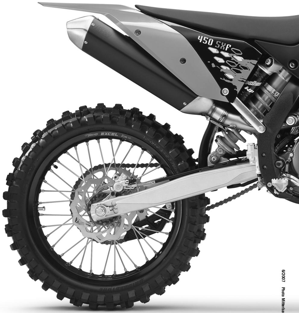
- Symbols used
- Formats used
- Use definition
- Maintenance
- Warranty
- Fuel, oils, etc.
- Spare parts, accessories
- Transport
- Note
- (450 XC-F, 505 XC-F)
- (450 SX-F, 505 SX-F)
- Environment
- Warning notes
- Info
- Grades of risks
- Danger
- Warning
- OWNER'S MANUAL
- Chassis number
- Type label
- Engine number
- Fork part number
- Shock absorber part number
- Clutch lever
- Hot start lever
- Possible states
- Hand brake lever
- Short circuit button
- Electric starter button
- Fuel tap (450 SX-F, 505 SX-F)
- Fuel tap (450 XC-F, 505 XC-F)
- Opening filler cap
- Closing filler cap
- Choke
- Shift lever
- Foot brake pedal
- Plug-in stand (450 SX-F, 505 SX-F)
- Side stand (450 XC-F, 505 XC-F)
- Advice on first use
- Running in the engine
- Checks before putting into operation
- Starting
- Conditions
- Starting up
- Shifting, riding
- Braking
- Stopping, parking
- Refueling
- Jacking up the motorcycle
- Removing the motorcycle from the work stand
- Checking the basic chassis setting with the rider's weight
- Compression damping of shock absorber
- Adjusting high-speed compression damping of the shock absorber
- Adjusting the low-speed compression damping of the shock absorber
- Adjusting rebound damping of the shock absorber
- Measuring rear wheel sag unloaded
- Check the riding sag of the shock absorber.
- Adjusting spring preload of the shock absorber
- Adjusting riding sag
- Removing the shock absorber
- Installing shock absorber
- Checking basic setting of fork
- Adjusting compression damping of fork
- Adjusting rebound damping of fork
- Bleeding fork legs
- Cleaning dust boots of fork legs
- Loosening the fork protection
- Positioning the fork protection
- Checking play of steering head bearing
- Adjusting play of steering head bearing
- Setting the fork offset
- Removing the fork legs
- Installing the fork legs
- Removing the fork protector
- Installing the fork protector
- Removing the lower triple clamp
- Installing the lower triple clamp
- Greasing the steering head bearing
- Dismounting the front fender
- Installing the front fender
- Dismount the start number plate
- Fitting the start number plate
- Handlebar position
- Adjusting handlebar position
- Checking gas Bowden cable route
- Checking play in gas Bowden cable
- Adjusting play in gas Bowden cable
- Checking chain dirt
- Cleaning the chain
- Checking the chain tension
- Checking the chain tension - fitting rear wheel
- Checking rear sprocket / engine sprocket for wear
- Checking chain wear
- Adjusting chain tension
- Adjusting chain tension - fitting rear wheel
- Adjusting chain guide (450 SX-F, 505 SX-F)
- Adjusting chain guide (450 XC-F, 505 XC-F)
- Brake fluid reservoir
- Brake calipers
- Checking brake discs
- Checking free play of hand brake lever
- Adjusting basic position of handbrake lever
- Checking front brake fluid level
- Topping up the front brake fluid
- Checking the front brake linings
- Removing front brake linings
- Mounting front brake linings
- Changing the fron brake linings
- Brake fluid DOT 5.1 (82)
- Checking free play of foot brake lever
- Adjusting basic position of footbrake lever
- Checking rear brake fluid level
- Topping up brake fluid of front brake
- Checking rear brake linings
- Removing rear brake linings
- Mounting rear brake linings
- Changing rear brake linings
- Removing front wheel
- Fitting front wheel
- Removing rear wheel
- Fitting rear wheel
- Tire condition checking
- Checking tire air pressure
- Checking spoke tension
- Removing the battery
- Installing the battery
- Recharging the battery
- Removing a fuse
- Replacing the fuse
- Ignition curve
- Ignition curve plug connection
- Changing ignition curve
- Removing the seat
- Mounting the seat
- Dismounting the fuel tank
- Installing the fuel tank
- Checking antifreeze and coolant level
- Checking the coolant level
- Alternative 1
- Alternative 2
- Draining coolant
- Refilling coolant
- Removing main silencer
- Fitting the main silencer
- Glass fiber yarn filling of main silencer
- Removing glass fiber yarn filling from the main silencer
- Fitting glass fiber yarn filling in main silencer
- Changing glass fiber yarn filling of main silencer
- Dismounting the air filter box lid
- Installing the air filter box lid
- Removing the air filter
- Installing the air filter
- Cleaning air filter
- Adjusting basic position of clutch lever
- Checking fluid level of hydraulic clutch
- Changing fluid level of hydraulic clutch
- Carburetor - idle
- Carburetor - adjusting idle
- Emptying the carburetor float chamber
- Checking engine oil level
- Changing engine oil and oil filter, cleaning oil screen
- Draining the engine oil
- Cleaning the oil screen
- Removing the oil filter
- Mounting oil filter
- Filling up with engine oil
- Topping up engine oil
- Cleaning motorcycle
- Storage
- Capacity- engine oil
- Capacity- cooling liquid
- WIRING DIAGRAM
- Super unleaded (ROZ, RON 95 / PON 91)
- according to
- Super unleaded (ROZ, RON 98 / PON 94)
- Brake fluid DOT 5.1
- Specification
- Supplier
- Coolant
- Mixture ratio
- Coolant (mixed ready to use)
- Hydraulic fluid (15)
- Engine oil (SAE 10W/50)
- FORK OIL (SAE 5)
- Universal oil spray
- Long-life grease
- Chain cleaner
- Offroad chain spray
- Cleaning substance for foam air filter
- Oil for foam air filter
- Motorcycle cleaner
- Cleaning and polishing materials for metal, rubber and plastic
- High-luster polish for paint
- Contact spray
- Engine oil (any)
- A
- B
- C
- D
- E
- F
Brand : KTM
Model : 450 XC-F
Category : Off-road motorcycle