
LASER56 - Electric heating ZIBRO - Free user manual and instructions
Find the device manual for free LASER56 ZIBRO in PDF.
| Product type | Electric convection heater |
| Brand | ZIBRO |
| Model | LASER56 |
| Power supply | 230 V ~ 50 Hz |
| Rated power | 2000 W |
| Dimensions (W × H × D) | 40 × 65 × 25 cm |
| Net weight | 6.5 kg |
| Recommended heating area | Up to 25 m² |
| Operating modes | Eco, Comfort, Frost-free |
| Built-in thermostat | Yes, adjustable from 5 to 35 °C |
| Programmable timer | Yes, 24h |
| Safety function | Tip-over protection, overheat shutdown, thermal fuse |
| Protection rating | IP24 (living room, bathroom zones 2 and 3) |
| Noise level | < 40 dB (silent) |
| Installation type | Wall-mounted or floor-standing with included feet |
| Maintenance | Dust with a soft dry cloth |
| Cleaning | Do not use abrasive agents or water |
| Spare parts | Thermal fuse, switch, power cord |
| Repairability | Repairability index: 8.2/10 |
| Warranty | 2 years |
| Color | White |
| Country of manufacture | France |
Frequently Asked Questions - LASER56 ZIBRO
User questions about LASER56 ZIBRO
0 question about this device. Answer the ones you know or ask your own.
Ask a new question about this device
Download the instructions for your Electric heating in PDF format for free! Find your manual LASER56 - ZIBRO and take your electronic device back in hand. On this page are published all the documents necessary for the use of your device. LASER56 by ZIBRO.
USER MANUAL LASER56 ZIBRO
Congratulations with your purchase of the Zibro, the number one brand among movable heaters. You have purchased a first-class quality product, which will serve you for many years to come. This, of course, provided you use the heater correctly. Please read these Directions for Use first, to ensure maximum lifetime for your Zibro.
Your heater comes with a 24-month manufacturer's warranty on all defects in material or workmanship.
We wish you much warmth and comfort with your Zibro.
Yours sincerely,
PVG International B.V.
Customer Service Department
1 READ THE DIRECTIONS FOR USE FIRST.
2 IN CASE OF ANY DOUBT, CONTACT YOUR ZIBRO DEALER.
WHAT YOU NEED TO KNOW IN ADVANCE
THE RIGHT FUEL
Only use Class C1 paraffin fuel in accordance with BS2869: Part 2, or equivalent. Your Zibro heater has been designed for use with high-quality water-free pure paraffin oil, such as Zibro Extra or Zibro Kristal. Only fuels of this kind will ensure clean and proper burning. Lower quality fuel may result in:
increased possibility of malfunctioning
incomplete burning
reduced heater lifetime
smoke and/or smells
deposits on the grid or mantle
Using the right fuel is therefore essential for safe, efficient, and comfortable use of your heater.
Always refer to your local Zibro dealer for the right fuel for your heater.
- The first time you ignite your heater it will smell like 'new' for a short time.
- Store your fuel in a cool and dark place.
- Fuel has a limited shelf life. Start every heating season with renewed fuel.
- The right quality of fuel will be assured, when you use Zibro Extra or Zibro Kristal for your heater.
- If you change to another brand and/or type of parrafin oil, you must first finish up all the remaining fuel in the heater.
TIPS FOR SAFE USE
1 Make sure that children are always aware of the presence of a burning heater.
2 Position the front of the heater at a distance of minimum 1.5 metres from walls, curtains, and furniture.
3 Do not use the heater in dusty rooms. You will not have optimum burning in such rooms. Do not use the heater in the immediate surrounding of a bath, a shower or a swimming pool.
4 Switch off the heater, before you leave or go sleeping. Unplug the heater as well, when you go away for a longer period of time (e.g. holidays).
5 Store and move fuel only in suitable tanks and jerrycans.
6 Make sure that the fuel is not exposed to heat or extreme temperature changes. Always store the fuel in a cool, dry and dark place (sunlight will affect the quality).
7 Never use the heater in places where harmful gasses or fumes may be present (e.g. exhaust gasses or paint fumes).
8 Beware that the grid of the heater becomes hot. If the appliance is covered there is a risk of fire.
Chapter 1, INSTALLATION
1. Introduction
This chapter contains all the relevant information, specifically:
Installation specifications
- List of installation tools
- Basic requirements for the installation of the fuel tank
- Instructions for the installation of the Laser System
The heater can be installed at any location, on condition that there is full compliance with electrical, fuel and emission regulations.
Before you start installing the heating system (possibly including electrical wiring and fuel supply equipment), check the local building and fire safety regulations. The requirements stipulated in these regulations must be respected in order to guarantee a legally approved installation and correct operation.

The heater was designed to be used to a maximum altitude of 1000m above sea level. Contact your dealer for the necessary adjustments if you wish to use it at a higher altitude.
2. Moving the heater
In addition to the space required for the heater, extra room must be kept free for air circulation. We recommend that you store fuel elsewhere. The Laser System can be placed on any type of flooring (including fitted carpets or other flammable materials) and operate safely, unless fuel or fire safety regulations specify otherwise. Check the gaps in the manner stipulated in the instructions in the manual.
Recommended tool kit
- Crosshead screwdriver
- Steel tape measure
- Felt-tip pen or pencil
- Cement for exterior use
- Electric drill (clockwise and anti-clockwise recommended)
- Hole cutting saw, jig saw or other tools suitable for sawing a hole of 70 - 80mm for the exhaust pipe
- Long drill
- Standard screwdrivers
- Adjustable spanners (various sizes)
10.Copper tube cutter - Reamer
12.Volt, Ohmmeter - Spirit level
- Plumber's tape for tube screw thread
- Small range of self-tapping screws
- Range of pliers (pin tongs, needle nose pliers, cutting pliers, locking pliers)
- Insulated screwdriver
- Protective material for your floor
- Container for fuel exhaust pipe
3. The electrical supply system
The electrical system must be protected from overloads by an at least 5-Ampere fuse or contact breaker.

Some installations (such as for use in mobile homes) must be fitted with a permanent connection to the household power circuits. This must be done by a recognised electrician.
4. Fuel tank
Heater fuel (exclusively water-free, pure paraffin oil) in 200/1000 litre storage tanks located outside. If large tanks are used, a pressure regulator with a max. of 2.5 PSI ( ± 0.17 bar) must be fitted at the inlet on the heater. This must be carried out in strict adherence to all local standards and/or building regulations.
Chapter 1, INSTALLATION
5. Wiring for the room temperature sensor
A temperature sensor that can be fitted to a wall measures the room temperature in order to automatically regulate the heating. The standard sensor wire is approximately 2.5m long.

The sensor may not be placed in a draught, direct sunlight or the warm air flowing out of the heater. This may cause incorrect temperature indications.
6. Unpacking
Save all packaging materials for possible future transportation.
A) Remove the cardboard (drilling) template and the user's manual from the packaging.
B) Remove the base plate and the box with the installation kit from the packaging.
C) Remove the heater from the packaging.
D) Remove the plastic bag covering the heater.
E) Remove the plastic bag containing the parts.
F) Remove the exhaust pipe from the bottom of the box.
G) Check that all parts are present.

Only the standard feed and exhaust system is supplied with the heater.
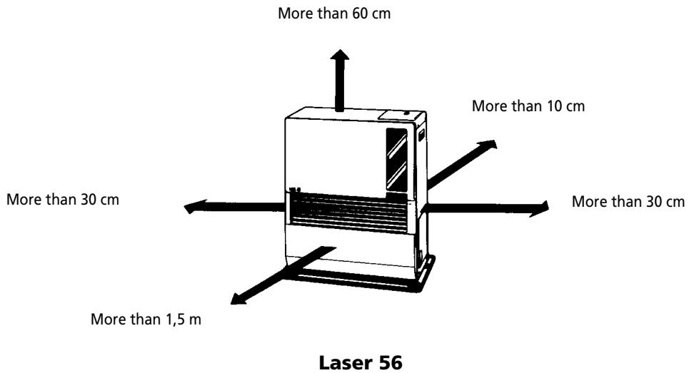
Fig. 1-1: Gaps heater/exhaust pipe
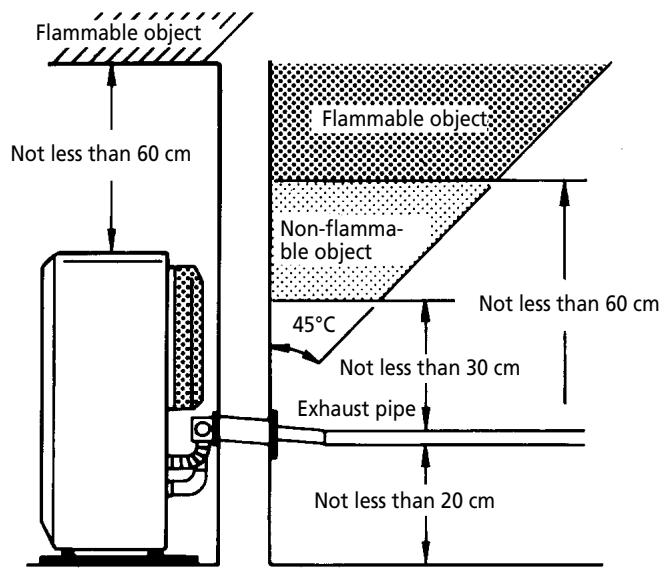
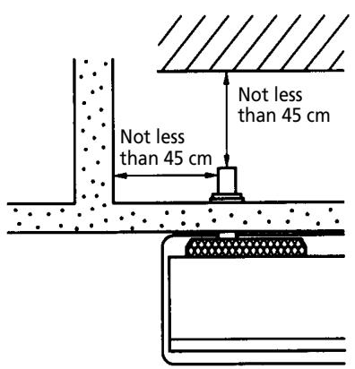
Fig. 1-1 (continued) gaps heater/exhaust pipe
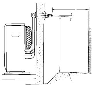
Frontal obstruction
45 cm or more
50 cm or more
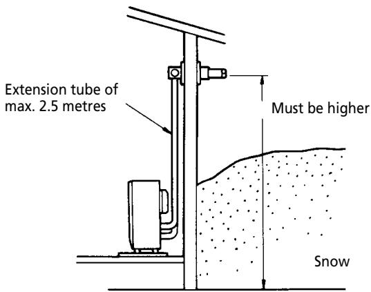
Snow-covered surface or ground
Important: The gap with the ground must be enlarged in areas subject to heavy snowfall.
Important: A windbreaker may be necessary in open areas that are subjected to strong winds.
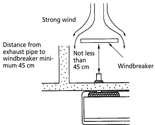
Fig. 1-2 Gaps heater/exhaust pipe
Chapter 1, INSTALLATION
After using the installation template as a guide for the drilling of the hole for the exhaust pipe, the Laser can be installed normally, according to the procedure in the illustration.
If the template is lost or the heater has to be moved, these are the dimensions and locations of the holes for the fuel pipe and exhaust pipe.
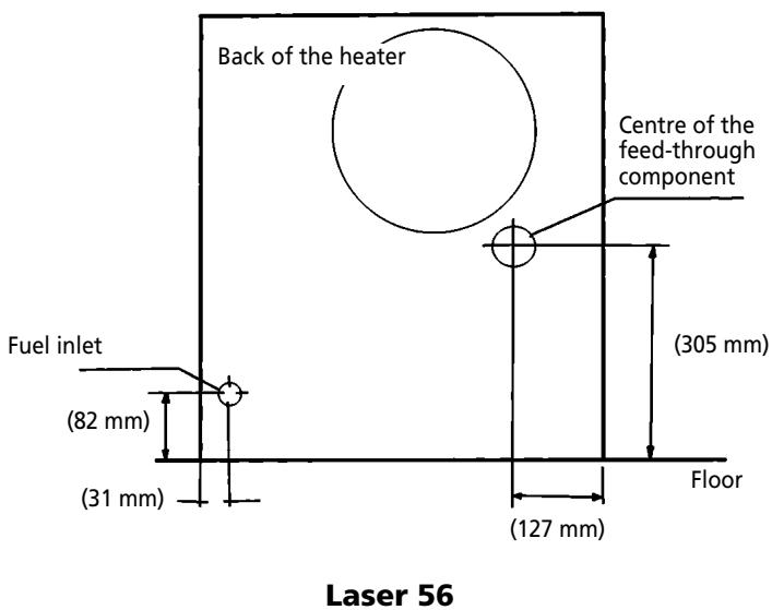
Fig. 1-3 Template

Do not remove any components from the heater. Always contact your dealer if repairs are required.
If the electricity cable is damaged, this may only be replaced with type H05 VV-F and by a recognised installer.
Chapter 1, INSTALLATION
Standard installation parts
The following list of standard installation parts is supplied with your heater. It may be necessary to order extra parts from your Zibro dealer if other installation methods are required.
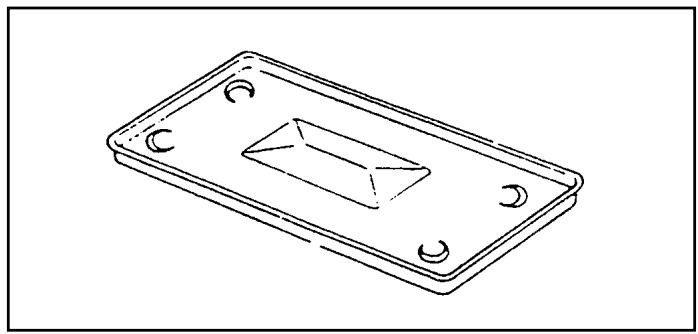
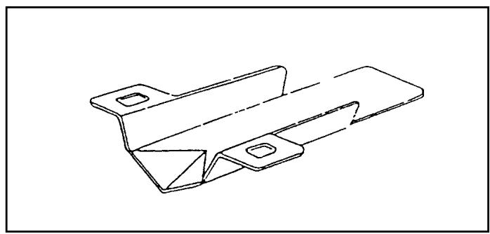
Base plate (1)
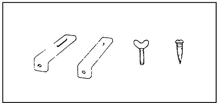
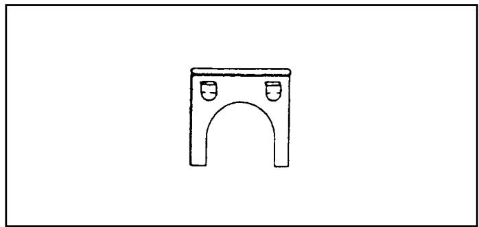
Wall hooks (2 set)
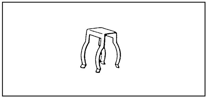
Pipe holder (2)
Pipe lock (1)
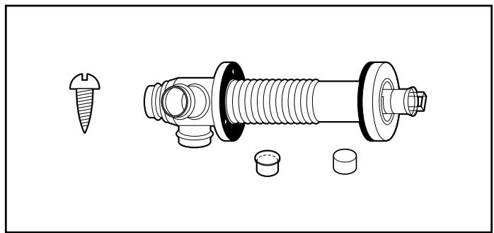
Exhaust pipe (1)
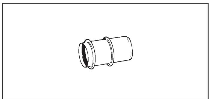
Exhaust Extension pipe (5) (1)
Chapter 1, INSTALLATION
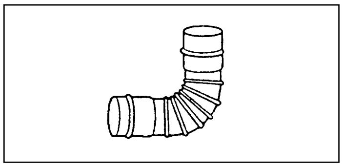
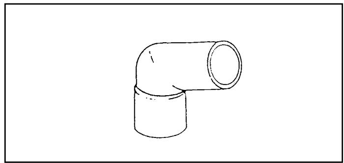
Right-angled exhaust pipe bend (1)
Discharge chute (1)
Right-angled air hose (2)
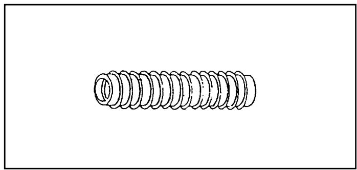
Flexible air hose (1)
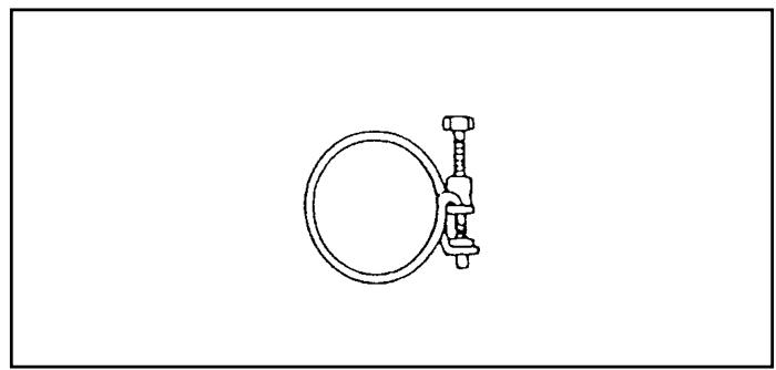
Hose clip (2)
Chapter 1, INSTALLATION
- For the standard installation, use the template supplied to position the hole for the exhaust pipe correct-
ly. Use cellotape or small nails to attach the template to the desired position on the wall (see Fig. 4).
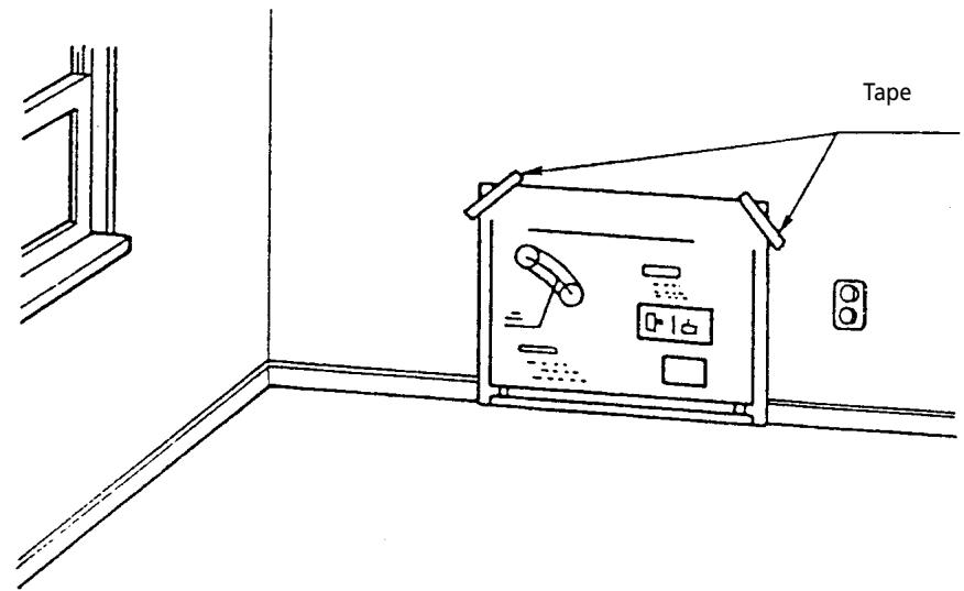
Fig. 4
Comment: The heater must be installed on a strong and stable floor. The floor must be flat and level. If this is not the case, the heater can be levelled by means of adjustable legs. This can be checked with the plumb line.
- Drill the hole for the exhaust pipe. Use a hole saw with a diameter of 70 80 ~mm (see Fig. 5). The opening on the interior side of the wall must be a little higher than the opening on the outside in order to create a slight gradient in the feed-through and exhaust pipe
after installation (approximately 2^ ) (see Fig. 6). This ensures that condensed water in the exhaust pipe flows to the outside and prevents the penetration of rainwater and snow after installation.
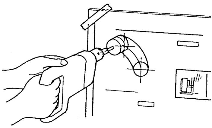
Fig. 5
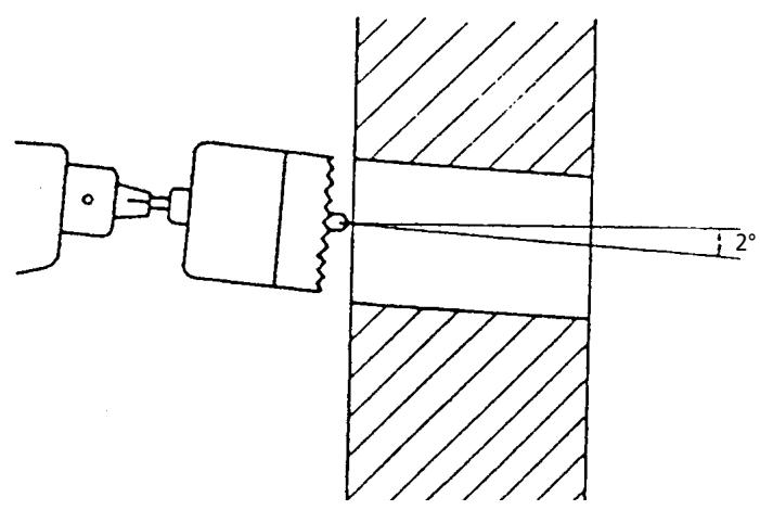
Fig. 6
Chapter 1, INSTALLATION
3. Install the inner flue pipe.
a. For wall thickness 230 320mm
From inside the room, insert the inner flue pipe through the hole. Make sure the arrow on the inner flue pipe is pointing up. Secure the inner flue pipe to the wall with the three wood screws. (See Fig. 7)

Fig. 7
b. For wall thickness 130 230mm
Remove Intake joint and Exhaust joint from Outer flue pipe (See Fig. 8).
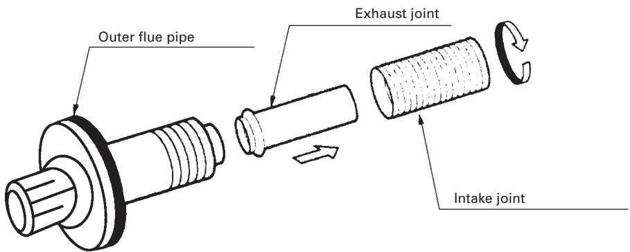
Fig. 8
Chapter 1, INSTALLATION
c. From outside, insert the outer flue pipe through the hole. Secure the outer flue pipe to the wall by turning it clockwise. This locks the two halves together (See Fig. 9).
IMPORTANT: Make sure the arrow on the outer flue pipe fringe is pointing up.
Make sure to secure the outer flue pipe well. (A-part shown in Fig. 9)
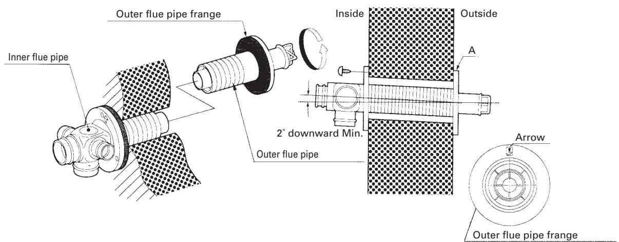
Fig. 9
- Attach the right-angled exhaust pipe bend to the outlet of the exhaust pipe. Cut, if necessary, the flexible air hose to size. Fasten the right-angled air hose to both ends of the flexible air hose – now attach the right-angled air hose to the inlet of the exhaust pipe. Attach the right-angled air hose to both ends of the flexible air hose. Now fasten the right-angled air hose to the inlet of the exhaust pipe.
Fasten the right-angled air hose onto the inlet with a hose clip. Seal the inlets and outlets that are not being used with the caps supplied. Check that the caps are firmly in position (See Fig.10). Use water or soap pads to provide lubrication when fitting the right-angled air hose onto the flexible air hose. The total length of the exhaust pipe may be a maximum of 3m (max. 3 bends).
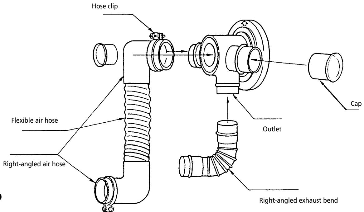
Fig. 10
Chapter 1, INSTALLATION
- In case the circuit board cover gets in the way of the connection of the standard flue pipe, use the extension pipe (S) for the exhaust outlet mouth of the heater (See Fig. 11).
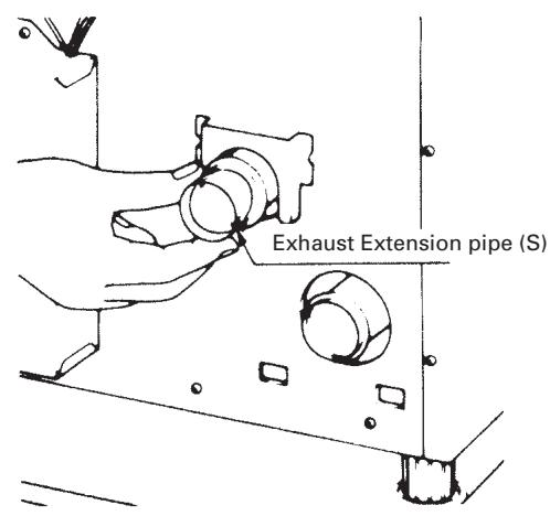
Fig. 11
- Place the heater in the desired location. Attach the right-angled exhaust bend to the outlet (the top open
ing) and attach the right-angled air hose to the inlet. Check that everything is firmly attached (See Fig. 12).
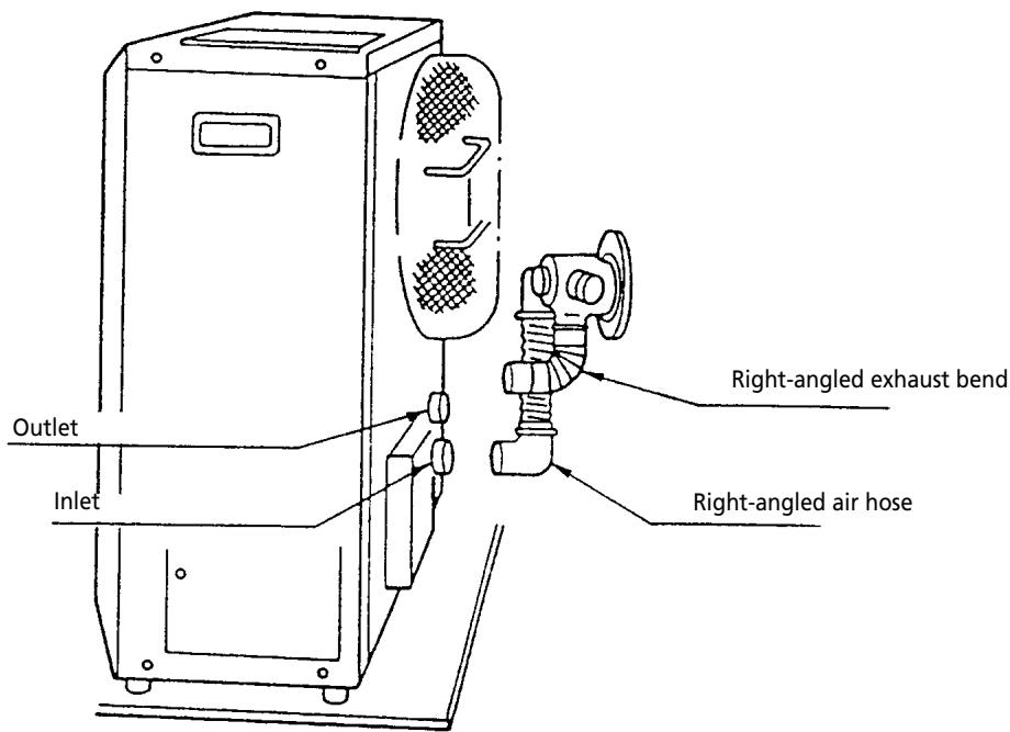
Fig. 12
Chapter 1, INSTALLATION
- Fasten the right-angled air hose to the inlet with the hose clip. Attach the right-angled exhaust bend to the exhaust pipe with the pipe holder (attach the pipe holder to the connection of the right-angled exhaust
bend). Attach the right-angled exhaust bend to the outlet by sliding the pipe lock into the outlet clip (See Fig. 13).
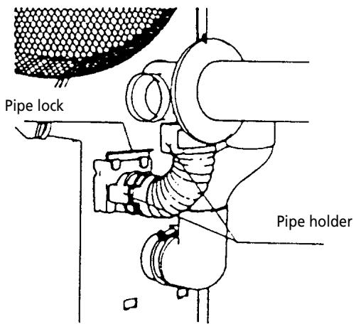
Fig. 13
- Installation of an external fuel tank
The installation of an external fuel tank is illustrated in a diagram (Fig. 1-11). The fact that installation techniques for fuel tanks vary means that it is impossible to provide a specific installation procedure. However, cer
tain criteria determine the manner in which the heater is supplied with fuel. Use the following checklist as a guideline for the installation of an external tank.
Chapter 1, INSTALLATION
CHECKLIST
- Check whether the heater has been connected to a suitable socket.
- Check that a suitable quantity of petroleum is in the fuel tank.
- Ensure that the fuel is free of water or other contaminants.
- Check that the fuel tank is in good working order – it must be free of rust, corrosion and/or leaks.
- Inspect the fuel pipe for signs of leaks, loose connections, cracks, air bubbles or blockages.
- Check that the fuel valves on the fuel tank and the fire safety valve are open in order to allow the free flow of fuel.
- Check outside the building in order to ascertain that there is no fuel or obstructions to the free circulation of air in the area immediately adjacent to the exhaust pipe.
- Inspect the inlet air hose for cracks, loose connections or blockages.
- Check the outlet air hose for cracks, loose connections or blockages.
- Check the back of the heater to ensure that the airflow to the air circulation ventilator is not obstructed.
- Inspect the interior of the building to ensure that the area immediately adjacent to the heater is free of fuel and objects that may obstruct the free flow of air.
- Check that the room sensor is not exposed to draughts, direct sunlight or heat radiated directly from the heater.
- Use a spirit level to check that the heater is level.
If this inspection brings any faults to light, resolve these problems before using the heater.

Use only water-free high quality pure paraffin oil. Never use benzene, LPG, camping gas or other flammable liquids. The use of these substances may cause explosions or fire.
Available fuel supply options
The fuel supply of the Laser 56 can be set up as follows:
Removable fuel tank
Insert the removable fuel tank in the top of the heater. Connect the free end of the fuel hose to the connecting piece of the removable fuel tank, pressing it firmly until you hear a click.
Check all parts for any fuel leaks.
Check on a weekly basis.
Large gravity-operated exterior tank
To install a large gravity-operated exterior tank, follow the instructions below. We recommend that you call in a recognised installer.
The inlet pressure to the heater may not exceed 2.5 psi. Use a pressure reduction valve with a maximum thrust of 2.5 psi (±0.17 bar).
The installation height of the bottom of the fuel tank must be 40~cm or more above the level of the floor on which the heater is standing. This will ensure that there is sufficient fuel inlet pressure. The distance between the floor surface on which the heater is standing and the top of the fuel tank may not exceed 2.5 metres.
This will prevent excessive fuel inlet pressures.
The pipe may not have any inverted U-bends (to prevent air pockets that may block the fuel supply).
We recommend using a water-blocking filter in the fuel pipe leading into the tank. A cut-off valve must be fitted to the tank.
We recommend installing a fire safety valve and a fuel filter in the fuel pipe.
The use of a cut-off valve, placed just before the pipe enters the building, will limit the quantity of fuel to be tapped off to a minimum if the heater requires maintenance.
Chapter 1, INSTALLATION
If a fuel pipe inside the building is more than 90~cm long, you must use an extra cut-off valve.
The external fuel tank must be placed at least 2 metres away from any heat source.
The external fuel tank must have a filling opening on the top and a ventilation opening with a weather-resistant cap on the side. Some tanks use the same opening for ventilation and filling.
Important: Ensure that the fuel pipe is free of dust and waste particles. These particles may cause problems in the fuel receptacle.
Copper tubing with an exterior diameter of 3/8'' must be used for the fuel pipe.
The installation of the external tank must meet fire safety regulation NFPA31 and/or applicable local regulations. Refer to the local authorities for these regulations.
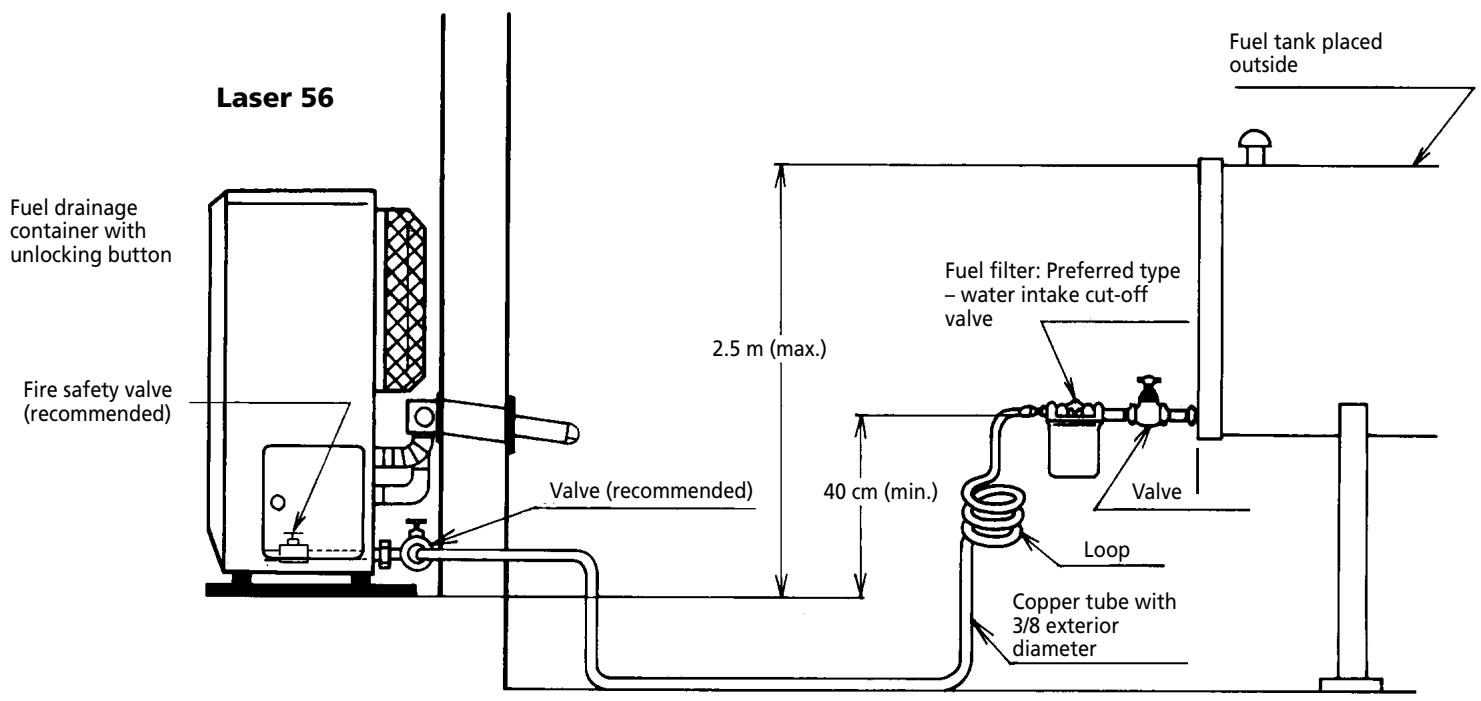
Fig.1-11 Connection to the fuel pipe
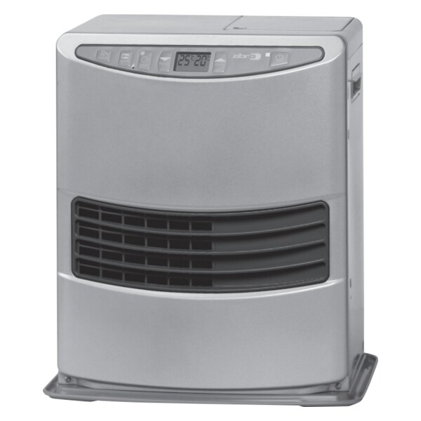
The Laser is an easy to use ventilated petroleum heater. It provides considerable quantities of heat, automatically regulates the room temperature, uses very little fuel and electricity and has options for automatic or manual operation.
This chapter provides all the information required for the operation of the Laser heater system. All specified operating procedures must be carried out in the order in which they are described.
2. Laser 56 heater specifications
| Low | Medium | High | |
| Heat yield (W) | 2400 | 4300 | 6400 |
| Fuel consumption (l/h) | 0.23 | 0.42 | 0.63 |
Nominal yield
(as applied to petroleum heaters): 93%
Power consumption:
| Setting | Setting | Setting | Setting | |
| Ignition | high | medium | low | off |
| 275 W | 60 W | 42 W | 35 W | 4 W |
Ventilator capacity: 5.7 / 4.2 / 2.8 cubic metre/min.)
- Fuel source: removable tank of 7 litres or external tank
Heating air as main heat source: 95 - 270m^3
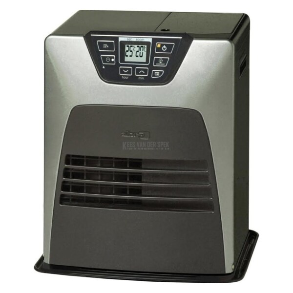
3. Operating elements and lights
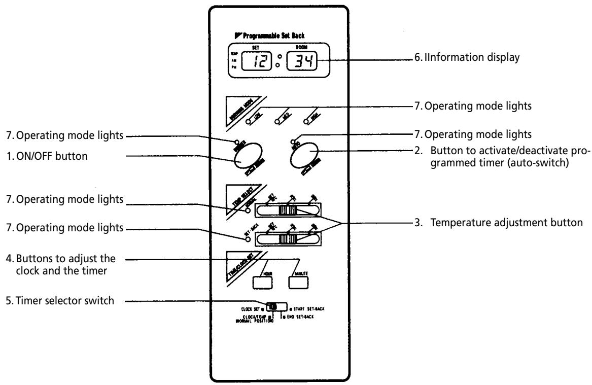
Fig. 2-1 Operation panel
- ON/OFF button:
The main switch to turn the heater on and off. Switch it "ON" to activate the heater. Combustion will start after a 3-9 minutes pre-heating period. The heater has 4 settings "HIGH", "MEDIUM", "LOW" and "OFF". - Button to activate/deactivate programmed timer. The switch activates and deactivates the automatic operation setting as programmed in the timer.
- Temperature adjustment button "NORMAL" and "SET-BACK" temperature selection switches offer the user the option to select the desired temperature during manual or automatic operation. Adjustment is extremely simple.
- Buttons to adjust the clock and the timer Timer and clock settings can be adjusted by pressing the hour and minute buttons.
- Time selector switch When the timer and the clock have been programmed and you wish to see a time indication,
return the selector switch to the 'normal' position. The start and finish times of "SET-BACK" (timer) are also set with this switch.
- Information display
Displays the clock, set temperature, room temperature and error codes.
-
Operating mode lights
-
indicate whether the heater is operating at the "HIGH", "MEDIUM" or "LOW" setting.
- Indicate when the heater is operating and flash when the heater is in the cleaning mode.
- Switch on during automatic operation.
- Switch on when the heater is operated manually or in "NORMAL" automatic operation.
- Switch on when the heater is "SET-BACK" setting of automatic operation.
Step 1: Open the valve(s)
Screw the valve on the top of the removable tank open or open the valve for the external fuel tank and the fire safety valve of the heater (if present).
Step 2: Start the fuel supply
Carefully press the red unlocking button for one second to release the float in the fuel receptacle.
The fuel receptacle only has to be unlocked when the heater is activated for the first time or after it has run out of fuel, or if the heater has not been used for an extended period of time. Unlocking may also be required if the fuel inlet pressure exceeds 2.5 psi (±0.17 bar). In this case, a pressure reduction valve must be installed.
Step 3: Adjust the clock
Important: The clock on the heater must always be set to the correct time.
A. Switch the time selector switch to "CLOCK SET"
B. Press the "HOUR" and the "MINUTE" buttons to adjust the hours and minutes. Pressing the "HOUR" or "MINUTE" button once will adjust the time by one unit (hours or minutes respectively). Holding the button down accelerates the adjustment of the time display.
All clock and timer settings are deleted if the power is cut off for a period longer than 10 seconds. The information display flashes "PM 12:00" when the heater is switched off. The clock and timer now have to be reprogrammed.
C. Set the timer switch to the "NORMAL" setting after completing the clock adjustment. The current time is then displayed on the digital indicator.
5. Manual operation
The heater is operated directly by the user. However, the heat yield is controlled automatically in accordance with the room temperature registered by the temperature sensor.
Step 1: Select manual operation
If the heater is in "AUTO" mode, switch the "AUTO"
switch to "OFF" to change to "MANUAL" operation.
Step 2: Switch the heater ON
Press the ON/OFF button until "ON" is displayed. The current room temperature and the set temperature are displayed on the information display.
The ON/OFF light starts to flash, after which the heater will switch on. The heater will not work if the room temperature is higher than the desired temperature setting.
Note: (*) The start-up time depends on the room temperature.
After 9-15 minutes, the heater will automatically select the correct operating mode and the ON/OFF button will now be illuminated continuously.
Room temperature:
under 0^ - 15 minutes
0^ - 15^ - 12 minutes
15^ -9 minutes
If no flames are visible after the start-up period, the heater will deactivate and then restart automatically. If flames are still not detected, the heater will deactivate and will have to be restarted manually (error code EE-2 on information display).
Step 3: Setting the room temperature
Slide the "NORMAL" temperature selector to the selected position in order to set the desired room temperature.
The desired temperature setting is shown in the information display when you set the room temperature.
The scale on the temperature selector only serves as a reference point. The figures on the information display and on the scale may differ, this is normal.
The operating mode is automatically controlled in accordance with the room temperature detected by the room temperature sensor. The heater works in the "HIGH" operating mode until the room temperature has reached the desired level.
When the room temperature reaches the chosen setting, the heater automatically switches to the "MED" or "LOW" operating mode in order to maintain the desired temperature. If the room temperature exceeds
the setting by approximately 2^ , the heater is switched off automatically. If the room temperature drops, the heater will automatically restart in order to maintain the desired temperature.
Note: The operating mode lights indicate the mode in which the heater is working at any one time. The heater switches automatically between the "HIGH", "MED" and "LOW" operating modes in order to maintain the desired temperature.
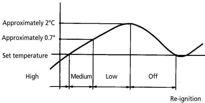
Fig. 2-2
6. Automatic operation
Automatic operation is initiated by programming the time/temperature settings for a specific time. Working in "SET-BACK" mode is programmed for a 24-hour period. This mode was developed to save energy by using a lower temperature setting, usually at night.
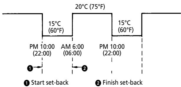
Fig. 2-3
Programming is carried out as follows (night setting): Ensure that the clock has already been programmed (see step 4, chapter 2-5).
Step 1: Set the start time of the "SET-BACK" mode
A. Slide the time selector switch to the "START SET-BACK" position.
B. Press "HOUR" and "MINUTE" to set the desired start and finish times. (pay attention to the AM or PM designation).
When setting the "SET-BACK" time, the "MINUTE" button will change in increments of 10 minutes (e.g. 10:00, 10:10, 10:20 etc.).
C. The start time of the "SET-BACK" mode is then shown in the information display (e.g. PM 10:00).
Step 2: Set the finish time of the "SET-BACK" mode. While the time selector switch is in the "END SET-BACK" mode, you must now programme the finish time in the same manner as described above (e.g. AM 6:00).
After programming, move the time selector switch back to the NORMAL position.
Step 3: Set the room temperature
Slide the "SET-BACK" temperature selector (night temperature) to the desired position (e.g. 15^ ). Turn the AUTO switch to the "ON" position.
Step 4: Set the ON/OFF switch to ON
If the temperature is lower than or drops below the requested temperature, the heater will start automatically.
7. Reprogramming the heater
In certain circumstances (e.g. power cuts), it may be necessary to reprogram the heater. Follow the steps specified above when reprogramming the timer. Do not forget to set the clock (step 4, chapter 2-5).
8. Cleaning system for the ignition rod
Automatic cleaning system of the ignition ignition rod
The heater will switch off automatically each day at 2:00 in the morning, allowing the ignition rod to clean itself for 10 minutes. CL: 10 will then appear in the display, changing every minute to CL:09, CL: 08, etc.
Manual cleaning system
The heater must be switched off during manual cleaning.
The ignition rod can be cleaned manually (10 minutes) in the following manner:
Press the 'Hour' and 'Minute' buttons simultaneously for 3 minutes.
CL: 10 will then appear in the information display.
Cleaning will then start automatically without any other input.
Attention: Cleaning the ignition is important in order to extend the life span of the ignition rod. We recommend cleaning the ignition rod at least once per week.
9. Room temperature sensor
The room temperature sensor is fitted with a 2.5 metre cable. This is located on the back of the heater.
Ensure that the cable does not touch the outlet tube.
The room temperature sensor can be installed with cellotape or with a wood screw.
Select the location where the sensor is to be installed in such a way that it will not be exposed to direct sunlight, draughts or the warm air flowing out of the heater.
10. Switching the heater off
Move the ON/OFF switch to the "OFF" (Auto-light, temperature light goes out) position. The operating mode light will start to flash until the flame disappears. The air circulation ventilator and the ventilator motor continue to operate for approximately 3 minutes in order to cool the heater down. Check that the ON/OFF light switches off when the ventilator has come to rest.
If you press the ON/OFF button during the cooling period, the heater will automatically restart at the end of this period.

Pull the plug out of the socket after the on/off light has switched off if the heater will not be used for an extended period of time.
11. Power cuts - recovery system
If a power cut occurs while the heater is in operation, all electrical systems will be switched off automatically. When power is restored, the heater will automatically re-ignite. However, this only happens in the manual mode.
The clock setting and Set-Back timer programme are deleted if the power cut lasts longer than 10 seconds. The AUTO light will flash when the power is restored. The heater must now be reprogrammed.
If a brief power cut occurs and the flame sensor continues to detect a flame, only the blower and circulation ventilators will reactivate when power is restored.
The "HIGH", "MED" and "LOW" operating mode lights will start to flash simultaneously (the igniter is not reactivated). Switch the heater off for a moment and then on again to return to normal operation.
12. Recovery after overheating
The heater is protected against damage caused by overheating.
A sensor will activate if the temperature in the housing exceeds 90^ C .
Step 1: Switch the heater OFF.
Step 2: Allow the heater to cool down.

Ensure that the metal housing has cooled sufficiently before touching it.
Under normal conditions, a period of 30 to 45 minutes is sufficient to allow the heater to cool down completely.
Step 3: Pull the heater plug out of the socket.
Step 4: Look for the source of the overheating. Overheating is usually caused by objects that obstruct the free flow of air. Check that the circulation ventilator or exhaust pipes are not blocked. Check that there are no objects blocking the outlet system (see also installation Fig. 1-1 and 1-2).
Step 5: Remove the front panel.
Step 6: Clean the inside of the heater.

Before starting to clean the heater, ensure that the interior is cool enough to touch. Wipe all dust off the outside of the housing with a clean, non-fluffy, damp cloth or another suitable cleaning aid. Do not forget to clean the outside of the heat chamber and the heat exchanger.
Step 7: Re-attach the front panel.
Step 8: Insert the heater plug into the socket.
Step 9: Switch the heater ON.
Step10: Re-programme the heater (clock and set-back timer).
Attention: If the heater overheats after the completion of a recovery procedure, contact your dealer and do not switch the heater on until the problem has been resolved.
13. Cleaning the filter (monthly)
The filter of the fuel pump must be cleaned each month and at the end of the heating season.
a) Open the flap on the right of the heater.
b) Close the cut-off valve on the fuel pipe.
c) Place the fuel collecting gutter under the float house in order to prevent fuel spills. Collect the fuel in a container.
d) Unscrew the plate covering the filter.
e) Remove the filter and clean it carefully with compressed air.
f) Replace the filter and screw the covering plate back into position.
g) Wipe away the spilled fuel.
h) Open the cut-off valve in the fuel pipe. Ensure that there are no fuel leaks.
Note: At the end of the heating season, remove any fuel remaining in the float house by unscrewing the drain plug.
14. Before consulting an expert
The following situations do not indicate defects.
While switching the heater on or off
White smoke can be seen when the heater is switched on for the first time.
Machine oil or dust on the burner chamber or heat exchanger is burning.
The flames flicker for several minutes after the heater has been ignited.
The ignition rod continues to function when the heater is cold, even several minutes after ignition. This may cause the flames to be a little larger.
The heater makes intermittent creaking sounds when warming up or cooling down.
Expansion and shrinkage of metal parts may cause a slight creaking sound.
Circulation of air in the room does not start immediately when the heater is lit.
To prevent unpleasant cold draughts, the ventilator only switches on when the heater has become warm.
A loud clicking sound can be heard during the first use or when the fuel runs out.
There is air in the fuel pump. This should be gone within approximately 1 minute.
If the clicking sound in the fuel pump does not stop after approximately 1 minute, push the red 'reset' button on the float chamber (do not hold it in). Also check whether all the fuel valves are open, the fuel filters are clean and whether there is sufficient fuel.
Note: The fuel pump may make a slight ticking sound during normal operation. This does not indicate a problem.
While the heater is in operation
A part of the burner pot and/or heat exchanger becomes red in colour during operation.
This is normal and does not indicate a problem.
Chapter 3, ERROR MESSAGES
| Error code | Problem | Cause | Solution |
| Power light is not lit. | The plug is not in the socket. | Insert the plug into the socket. | |
| The print plate does not function correctly. | Check the fuse or contact your dealer. | ||
| EE2 | No ignition. | No fuel. | Check fuel meter, top up if necessary. |
| The fuel tank valve is closed. | Open the valve by turning it anticlockwise. | ||
| Air bubble in the fuel pipe. | Press the red reset button. | ||
| Blocked exhaust pipe. | Clean the exhaust pipe. | ||
| Blocked fuel filter. | Clean the fuel filter. | ||
| Defective ignition, print plate or fuel pump. | Contact your dealer. | ||
| EE6 | Flame goes out immedi- diately after ignition. | Air bubble in fuel pipe. | Press the red reset button. |
| No fuel. | Check the fuel meter on the tank, top up if necessary. | ||
| Overheating safety feature is activated. | Clean the protective cap on the ventilator, remove dust and obstacles. | ||
| Defective flame sensor. | Contact your dealer. | ||
| Fuel supply is blocked. | Contact your dealer. | ||
| Pressure on fuel supply is incorrect. | Adjust the pressure on the fuel supply to a maximum of 2.5 PSI (±0.17 bar). | ||
| Float mechanism does not work. | Contact your dealer. | ||
| Poor/noisy combustion. | Soot formation in the exhaust pipe. | Remove the soot from the exhaust pipe. | |
| Burner ring is fitted incorrectly. | Contact your dealer. | ||
| Altitude above sea level too great. | Contact your dealer. | ||
| Excessive wind pressure in the exhaust pipe. | Place a windbreaker. | ||
| Odours. | Leaking exhaust pipe. | Check/repair the exhaust pipe (Pay special attention to all the connections) | |
| Fuel leak. | Check/repair all the connections in the fuel supply pipe. | ||
| Poor sealing in/at the burner chamber. | Contact your dealer. | ||
| EE8 | Defective blower motor | Contact your dealer. | |
| EE10 | Heater will not switch off. | Too much fuel in the burner. | Contact your dealer. |
| Hi | The room temperature is higher than 35°C. | Check that the room temperature sensor is in the correct position. | |
| Lo | The room temperature is lower than -10°C. | Check that the room temperature sensor is in the correct position. |
Warning: Stop using the heater if error EE10 occurs. Only restart the heater when this problem has been resolved. Note: If you have checked/remedied all possible causes of the problem and the heater will not start after 3 attempts, contact your dealer.
Chapter 4, WARRANTY PROVISIONS
Your heater comes with a 24-months warranty starting on the date of purchase. Within this period all defects in material or workmanship will be repaired without any charge. The following provisions shall apply regarding this warranty:
1 We expressly dismiss all other claims for damages, including consequential damages.
2 Any repairs or replacements of components within the term of warranty will not result in an extension of the term of warranty.
The warranty shall no longer apply, when the heater has been modified, non-original parts have been used, or when it is repaired by third parties.
4 The warranty shall not apply to parts that are subject to normal wear, such as the burner mat and the manual fuel pump.
5 The warranty shall only apply, when you present the original, dated proof of purchase, provided no changes have been made to it.
The warranty shall not apply to damages caused by actions not in compliance with the Directions for Use, neglect, and the use of an incorrect type of fuel, or fuel past its use-by date. The use of incorret fuel can even be dangerous*.
7 Transportation costs and the risks involved during the transportation of the heater or heater components shall always be for the account of the purchaser.
In order to avoid unnecessary costs, we recommend that you always read the 'Directions for Use' carefully first. In case they offer no solution, please take the heater to your dealer for repair.
- Highly inflammable substances may induce uncontrollable burning, causing flames to break out. Should this happen, never try to move the heater, but always switch off the heater immediately. In case of emergency you may use a fire extinguisher, but only a type B extinguisher: a carbon dioxide or powder extinguisher.
DISTRIBUTED IN EUROPE BY PVG INTERNATIONAL BV
A ÖSTERREICH
Holloway Bank, Wednesbury
West Midlands WS10 OAW
tel.: +44 121 506 1818
fax: +44 121 505 1744
email: gases@lister.co.uk
ITALIA
PVG Italy SRL
Via Niccolò Copernico 5
50051 CASTELFIORENTINO (FI)
tel: +39 571 628 500
fax: +39 571 628 504
email: pvgitaly@zibro.com
N NORGE
Sunwind - Gylling A/S
Rudsetta 71-75 / P.O. Box 64
N-1309 RUD
tel: +4767171370
fax: +47 67 17 13 80
email: pvgint@zibro.com
NEDERLAND
PVG International B.V.
P.O.Box 96
5340 AB OSS
tel: +31 412 694 694
fax: +31 412 622 893
email: pvgnl@zibro.com
PORTUGAL
Gardena, Lda


- WHAT YOU NEED TO KNOW IN ADVANCE
- THE RIGHT FUEL
- TIPS FOR SAFE USE
- Chapter 1, INSTALLATION
- Introduction
- Moving the heater
- Recommended tool kit
- The electrical supply system
- Fuel tank
- Wiring for the room temperature sensor
- Unpacking
- Standard installation parts
- Install the inner flue pipe.
- CHECKLIST
- Available fuel supply options
- Laser 56 heater specifications
- Operating elements and lights
- Manual operation
- Automatic operation
- Reprogramming the heater
- Cleaning system for the ignition rod
- Manual cleaning system
- Room temperature sensor
- Switching the heater off
- Power cuts - recovery system
- Recovery after overheating
- Cleaning the filter (monthly)
- Before consulting an expert
- Chapter 3, ERROR MESSAGES
- Chapter 4, WARRANTY PROVISIONS
- DISTRIBUTED IN EUROPE BY PVG INTERNATIONAL BV
- A ÖSTERREICH
- ITALIA
- N NORGE
- NEDERLAND
- PORTUGAL
Brand : ZIBRO
Model : LASER56
Category : Electric heating