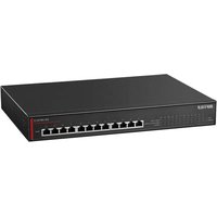
BS-MP2012 - Network card BUFFALO - Free user manual and instructions
Find the device manual for free BS-MP2012 BUFFALO in PDF.


| Product Type | Network Interface Card |
| Brand | Buffalo |
| Model | BS-MP2012 |
| Form Factor | PCI Express x1 |
| Data Transfer Rate | 1000 Mbps (Gigabit Ethernet) |
| Network Interface | RJ-45 (10/100/1000Base-T) |
| Compliance Standards | IEEE 802.3, IEEE 802.3u, IEEE 802.3ab |
| Bus Type | PCI Express 2.0 x1 |
| Power Consumption | 2.5 W (typical) |
| Operating Temperature Range | 0°C to 55°C |
| Storage Temperature Range | -20°C to 70°C |
| Operating Humidity Range | 10% to 90% (non-condensing) |
| Dimensions (W x H x L) | 2.7 x 0.7 x 5.2 in (68 x 17 x 132 mm) |
| Weight | 1.8 oz (50 g) |
| LED Indicators | Link/Activity, Speed (100/1000) |
| Supported Operating Systems | Windows, Linux, macOS |
| Warranty | Limited Lifetime |
| Package Contents | Network card, low-profile bracket, driver CD, user manual |
Frequently Asked Questions - BS-MP2012 BUFFALO
User questions about BS-MP2012 BUFFALO
0 question about this device. Answer the ones you know or ask your own.
Ask a new question about this device
Download the instructions for your Network card in PDF format for free! Find your manual BS-MP2012 - BUFFALO and take your electronic device back in hand. On this page are published all the documents necessary for the use of your device. BS-MP2012 by BUFFALO.
USER MANUAL BS-MP2012 BUFFALO
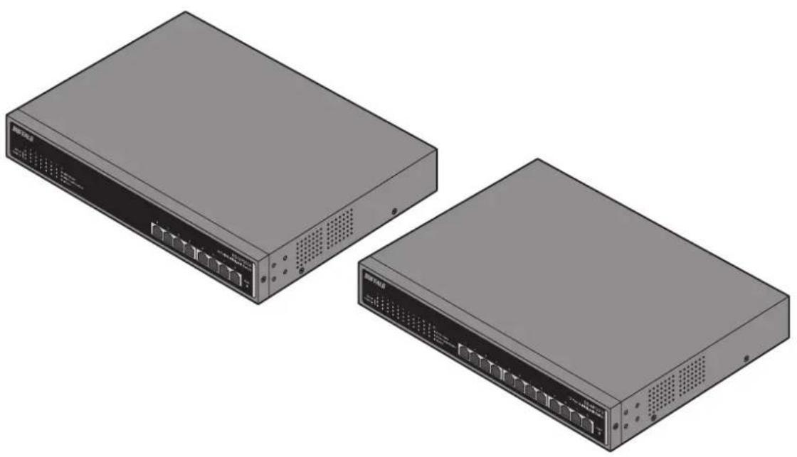
Layer 2 MultiGigabit Switch
BS-MP20 Series
User Manual
Americas: www.buffaloamericas.com
Europe: www.buffalo-technology.com
Asia Pacific: www.buffalo-asia.com
Contents
Chapter 1 Initial Settings ....4
Product Requirements......4
Install Business Switch Configuration Tool ....4
Change Switch's IP Address....5
Open Settings.... 10
Change Username and Password 14
MAC Address Learning 15
Chapter 2 Settings....16
Menu 16
System Information 17
System....17
System IP Settings....18
VLAN 19
VLAN Settings 19
VLAN Ports 20
MAC Addresses....21
Static MAC Filtering 21
Port Settings.... 21
Status....21
Speed/Mode Settings 23
System Security 24
Administration Account 24
QoS 25
QoS Settings....25
QoS Mapping....27
VoIP Auto Priority 28
Security 29
Auto DoS Attack Prevention 29
Port Trunking.... 30
Traffic Control.... 31
Mirroring.... 32
IGMP 32
Status 32
IGMP Settings....32
IGMP Querier....33
IGMP Router Port 34
Loop Prevention....35
Update Firmware....36
Back Up and Restore 36
Reboot.... 37
Initialize 37
Statistics.... 38
Network Diagnostics....39
Chapter 3 Troubleshooting....40
LED Is Not Lit, Abnormal Lighting or Blinking......40
Cannot Access Settings......40
Forgot the Username or Password 40
Appendix A Specifications......41
Product Specifications....41
Port Specifications....41
Factory Default Settings....42
Appendix B Regulatory Compliance Information.....44
For Customers in the United States 44
For Customers in Europe 45
Chapter 1 Initial Settings
Product Requirements
Compatible Devices and Browsers
Compatible Devices to Connect to BS-MP
10GBASE-T/5GBASE-T/2.5GBASE-T/1000BASE-T/100BASE-TX compatible devices (Computer, NAS, switches)
Compatible Browsers to Enter Settings
Microsoft Edge
Internet Explorer 8/9/10/11
Mozilla Firefox
Google Chrome
Refer to our website to check the latest information on compatible browser versions.
Install Business Switch Configuration Tool
Install "Business Switch Configuration Tool" before you perform the following procedure. (Compatible with Windows only.)
Note: You can download the latest version of Business Switch Configuration Tool from the URLs below:
BS-MP2008 http://d.buffalo.jp/bs-mp2008/
BS-MP2012 http://d.buffalo.jp/bs-mp2012/
Change Switch's IP Address
To enter Settings, the switch's web user interface, the switch's IP address should belong to the same segment as your computer's IP address.
1 Connect the switch to your computer and your network with an Ethernet cable (sold separately). Confirm that link/act LED of the connected port is on.
2 Double-click the "Business Switch Configuration Tool" icon to open Business Switch Configuration Tool.
3 Click Next to start searching for the switch.

4 Select the switch and click Next.
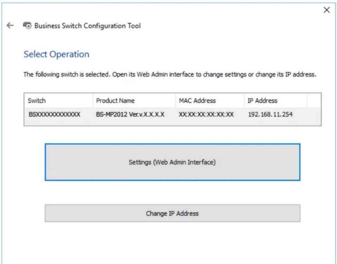
5 Click Change IP Address.


Business Switch Configuration Tool
Select Operation
The following switch is selected. Open its Web Admin interface to change settings or change its IP address.
| Switch | Product Name | MAC Address | IP Address |
| BSXXXXXXXXXXXXX | BS-MP2012 Ver.v.X.X.X.X | XX:XX:XX:XX:XX:XX | 192.168.1.254 |
Settings (Web Admin Interface)
Change IP Address
6 Configure the switch's IP address to match the segment of the IP address of your computer and click Next.
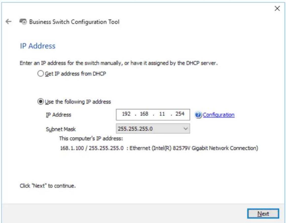
7 If the password input screen is displayed, enter "password" and click Next.

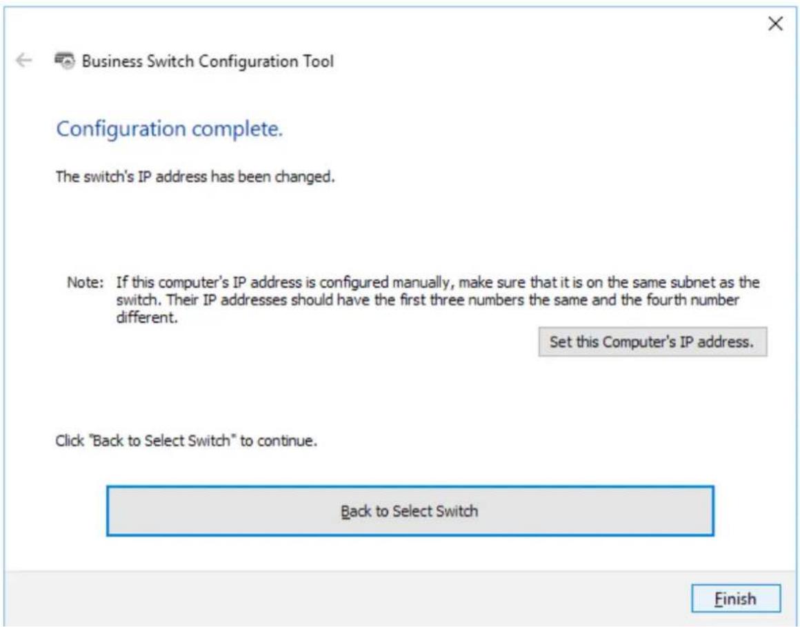
8 Click Finish.
Open Settings
1 Configure the switch's IP address, referring to the "Change Switch's IP Address" section above.
2 Double-click the "Business Switch Configuration Tool" icon to open Business Switch Configuration Tool.
3 Click Next to start searching for the switch.


Business Switch Configuration Tool
Getting Started
This utility will search for connected Business Switches on your network. It will let you easily open the configuration interface or change the IP address for Business Switches.
Click "Next" to continue.
Business Switch Configuration Tool Version 2.0.14
Next
4 Select the switch and click Next.

5 Click Settings (Web Admin Interface).
6 Click OK.

7 A web browser is launched and the login screen is displayed. Enter "admin" as the username and "password" as the password, then click Log In.

Note: There is a message window, "The switch's configuration interface is now open in a browser window." under the browser window. Click Complete to close the window.
Change Username and Password
To change the default username and password from "admin" and "password", refer to the following procedure.
1 Open Settings.
2 Navigate to Basic - System Security - Administration Account.
3 Enter your new username and password (also fill the "Confirm Password" field), then click Apply.
Note: You may enter up to 8 alphanumeric characters, hyphens (-), and underscores (_) for the new username and password.

4 Enter the new username and password, then click Log In.

MAC Address Learning
This switch uses SVL (Shared VLAN Learning) to learn MAC addresses. SVL is a method that retains a shared MAC address table for the entire switch. It differs from IVL, which retains a MAC address table for each VLAN. Be sure you understand how SVL works before you create a VLAN with the switch.
Differences between Operation of SVL and IVL
![graph TD Switch1["Switch 1"] -->|VLAN 1 VLAN 2| VLAN1["VLAN 1"] Switch1 -->|VLAN 1 VLAN 2| VLAN2["VLAN 2"] Switch2["Switch 2"] -->|VLAN 1| PC1["PC 1 (VLAN 1, PVID 1)"] Switch2 -->|VLAN 1| PC2["PC 2 (VLAN 2, PVID 2)"] Switch1 -->|VLAN 3| PC3["PC 3 (VLAN 1, 2, 3 PVID 3)"] Switch2 -->|VLAN 3| PC3 Switc…](/content/2026/07/1459704/images/c19f931661664820b87a239b96891059c2117303398b82f8c78fc2f1b2a81d67.jpg)
SVL
When PC 1 and PC 3 communicate, PC 3 is learned by port 1 on switch 2 so PC 2 and PC 3 cannot communicate.
IVL
When PC 1 and PC 3 communicate, PC 3 is learned by both VLAN 1 and VLAN 2 so PC 2 and PC 3 can communicate. However, frames sent from PC 3 to PC 1 are also delivered to PC 2.
Chapter 2 Settings
Refer to the "Open Settings" section in chapter 1 to access Settings.
Menu
| System Information Displays the switch's information. | ||
| Basic | ||
| System Configure the switch's name, location, and contact. | ||
| System IP Settings | Configure the switch's IPv4 address, subnet mask, and default gateway. | |
| VLAN | VLAN Settings | Confirm VLAN status and create new VLAN. This switch's IP address can also be configured on this page. |
| VLAN Ports Configure PVID (Port VLAN ID). | ||
| MAC Addresses Static MAC Filtering Configure static MAC address-based filtering. | ||
| Port Settings | Status Displays port status. | |
| Speed/Mode Settings Configure transmission rate and flow control for each port. | ||
| System Security | Administration Account | Configure administration username and password. |
| Advanced | ||
| QoS | QoS Settings Configure QoS priority. | |
| QoS Mapping Configure QoS mapping for each priority. | ||
| VoIP Auto Priority Configure priority for SIP, H.323, SCCP. | ||
| Security | Auto DoS Attack Prevention | Configure to drop specified packets. |
| Port Trunking Configure port trunking. | ||
| Traffic Control Configure traffic storm control. | ||
| Mirroring | Configure to monitoring traffic. | |
| IGMP | Status Displays IGMP status. | |
| IGMP Settings | Configure IGMP snooping. | |
| IGMP Querier | Configure IGMP querier. | |
| IGMP Router Port | Specify ports to connect to multicast routers. | |
| Loop Prevention | Configure loop prevention settings. | |
| Management | ||
| Update Firmware | Update firmware from a local file. | |
| Back Up and Restore | Save settings to a file or restore settings from a file. | |
| Reboot Reboot the switch. | ||
| Initialize | Initialize the switch. | |
| Statistics | Displays the switch's statistics. | |
| Network Diagnostics | Execute communication test to the specified IP address. | |
System Information
Displays the switch's information.
| System Information | |
| Product Name | BUFFALO BS-MP2012 |
| Switch Name | XXXXXXXXXXXXXX |
| Location | Not defined |
| System Contact | Not defined |
| MAC Address | XX:XX:XX:XX:XX:XX |
| IPv4 Address | |
| Method of Acquiring IPv4 Address | Acquire from DHCP Server |
| IPv4 Address | 192.168.1.254 |
| Subnet Mask | 255.255.255.0 |
| Default Gateway | 0.0.0.0 |
| Version | |
| Firmware Version | 1.0.2.4/Oct 5 2016 19:08:32 |
| Boot Code Version | 0.0.0.0/Jun 03 2016 17:17:54 |
| Hardware Version | Version/0 |
| System Information Displays | system information such as the switch name, and MAC address. |
| IPv4 Address | Displays information such as the switch's IPv4 address, subnet mask, and default gateway. |
| Version Displays the switch's | firmware, boot code, and hardware versions. |
System
Configure the switch's name, location, and contact.
| System Configuration | ||
| Switch Name | XXXXXXXXXXXXXX | (Up to 50 alphanumeric characters, “-”, “_) |
| Location | Not defined | (Up to 50 alphanumeric characters, “-”, “_”, and spaces) |
| Contact | Not defined | (Up to 50 alphanumeric characters, “-”, “_”, and spaces) |
Apply
| Switch Name | Enter the switch's name. You may enter up to 50 alphanumeric characters, hyphens (-), and underscores (_). |
| Location | Enter the location of the switch. You may enter up to 50 alphanumeric characters,hyphens (-), underscores (_), and spaces. |
| Contact | Enter the contact information of the switch. You may enter up to 50 alphanumeric characters, hyphens (-), underscores (_), and spaces. |
System IP Settings
Configure the switch's IPv4 address, subnet mask, and default gateway.

Apply
| Method of Acquiring IPv4 Address | Select a method of obtaining the switch's IPv4 address.Obtain from DHCP ServerObtain the switch's IPv4 address from DHCP server.Static IP AddressEnter the IP address manually. |
| IPv4 Address | Enter the switch's IPv4 address if you select Static IP Address as the connection method. |
| Subnet Mask | Enter the switch's subnet mask if you select Static IP Address as the connection method. |
| Default Gateway | Enter the switch's default gateway if you select Static IP Address as the connection method. |
VLAN Settings
Confirm VLAN status and configure new VLAN.

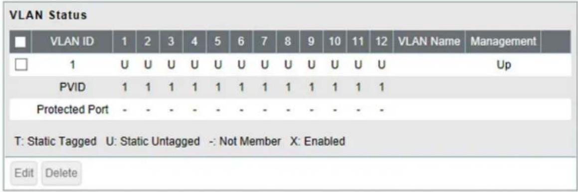


| Mode | Select a VLAN mode from "VLAN Settings" or "Privacy Separator". Privacy separator is a mode that enables communication to the router from a port but blocks communication between ports.Note: VLAN and privacy separator cannot be used at the same time. |
| VLAN Status | Displays current VLAN and PVID (Port VLAN ID) status. Click Edit to edit the VLAN selected. Click Delete to delete the VLAN selected. VLAN 1 cannot be deleted. |
| VLAN ID Specify VLAN ID from 2-4094. | |
| VLAN Name | Enter the VLAN name. You may enter up to 17 alphanumeric characters, hyphens (-), and underscores (_). |
| Management VLAN | Check it if the VLAN is a management VLAN. Only devices which belong to the management VLAN can open Settings. |
| Tagged Select when you assign the port to tag member. | |
| Untagged Select when you assign the port to untag member. | |
| Not Member Select when you do not assign the port to any member. | |
| Reset Click to reset the changes to the previous settings. | |
| Uplink | Appears when "Privacy Separator" is selected.A router should be connected to the uplink port to connect to the Internet. Uplink ports can communicate with all downlink ports. Specify at least 1 port to an uplink port. |
| Downlink | Appears when "Privacy Separator" is selected.Downlink ports are the ones which each device connected to. Downlink ports can communicate with uplink ports, but cannot communicate with each downlink port. |
Note: In privacy separator mode, only the device connected to an uplink port can open Settings. If you configure the port that your computer is connected as a downlink port, you cannot open Settings any more.
VLAN Ports
Configure PVID (Port VLAN ID).
| Port | PVID | Acceptable Frame Type | Ingress Filter☑ | Protected Port☐ |
| 1 | 1 | Admit All √ | ☑ | ☐ |
| 2 | 1 | Admit All √ | ☑ | ☐ |
| 3 | 1 | Admit All √ | ☑ | ☐ |
| 4 | 1 | Admit All √ | ☑ | ☐ |
| 5 | 1 | Admit All √ | ☑ | ☐ |
| 6 | 1 | Admit All √ | ☑ | ☐ |
| 7 | 1 | Admit All √ | ☑ | ☐ |
| 8 | 1 | Admit All √ | ☑ | ☐ |
| 9 | 1 | Admit All √ | ☑ | ☐ |
| 10 | 1 | Admit All √ | ☑ | ☐ |
| 11 | 1 | Admit All √ | ☑ | ☐ |
| 12 | 1 | Admit All √ | ☑ | ☐ |
Apply Reset
| PVID | Specify the port VLAN ID. The received untagged frames will be recognized as the specified VLAN ID. (1-4094) |
| Acceptable Frame Type | Admit AllReceive both untagged and tagged frames.Tagged OnlyReceive tagged frames only and drop untagged frames. |
| Ingress Filter | EnableDrop frames if the received frame's VLAN ID is not a member of incoming port's VLAN.DisableAll tagged and untagged frames will be received. |
| Protected Port "Protected Port" enabled ports cannot communicate with each other. | |
MAC Addresses
Static MAC Filtering
Configure the filtering of MAC addresses that are registered manually. Only the frames with a registered MAC address as a source MAC address can pass through the ports that the MAC address is registered to.

| Static MAC Filtering Check "Enable" to enable static MAC filtering. | |
| MAC Address | Enter the MAC address you want to filter. (Example: 00:11:22:aa:bb:cc)Up to 8 addresses can be registered per port. |
| Port Number Select a port to | apply the static MAC filter. |
| Static MAC Filtering Table Displays the registered MAC addresses and port numbers. | |
Note: This function is not compatible with multicast MAC addresses, VRRP MAC addresses (00:00:5E:00:01:XX), or broadcast MAC addresses.
Port Settings
Status
Displays the port status.
| Port | Name | Admin | Link Status | Autonegotiation | Speed/Duplex | Flow Control | IEEE 802.3az | APD | Jumbo Frame |
| 1 | Port 1 | On | Down | On | 10GbpsFull | Off | On | Off | On |
| 2 | Port 2 | On | Down | On | 10GbpsFull | Off | On | Off | On |
| 3 | Port 3 | On | Down | On | 10GbpsFull | Off | On | Off | On |
| 4 | Port 4 | On | Down | On | 10GbpsFull | Off | On | Off | On |
| 5 | Port 5 | On | Down | On | 10GbpsFull | Off | On | Off | On |
| 6 | Port 6 | On | Down | On | 10GbpsFull | Off | On | Off | On |
| 7 | Port 7 | On | Down | On | 10GbpsFull | Off | On | Off | On |
| 8 | Port 8 | On | Down | On | 10GbpsFull | Off | On | Off | On |
| 9 | Port 9 | On | Down | On | 10GbpsFull | Off | On | Off | On |
| 10 | Port 10 | On | Down | On | 10GbpsFull | Off | On | Off | On |
| 11 | Port 11 | On | Down | On | 10GbpsFull | Off | On | Off | On |
| 12 | Port 12 | On | Up | On | 1000MbpsFull | Off | On | Off | On |
| Name Displays the port name. | |
| Admin Displays whether the port is enabled (on) or disabled (off). | |
| Link Status Displays whether the link is up or down. | |
| Autonegotiation Displays whether the autonegotiation is enabled (on) or disabled (off). | |
| Speed/Duplex Displays the speed and duplex status. | |
| Flow Control Displays whether the flow control is enabled (on) or disabled (off). | |
| IEEE 802.3az Displays whether IEEE 802.3az is enabled (on) or disabled (off). | |
| APD Displays whether APD is enabled (on) or disabled (off). | |
| Jumbo Frame | Displays whether jumbo frame is enabled (on) or disabled (off).Note: Jumbo frames of up to 9216 frames (including header 14 bytes + FCS 4 bytes) can be forwarded. |
Speed/Mode Settings
Configure ports settings such as the transmission rate or flow control.
| Port | Name | Admin | Mode | Flow Control | IEEE 802.3az | APD | Jumbo Frame | Speed/Duplex |
| 1 | Port 1 | Autonegotiation | - | |||||
| 2 | Port 2 | Autonegotiation | - | |||||
| 3 | Port 3 | Autonegotiation | - | |||||
| 4 | Port 4 | Autonegotiation | - | |||||
| 5 | Port 5 | Autonegotiation | - | |||||
| 6 | Port 6 | Autonegotiation | - | |||||
| 7 | Port 7 | Autonegotiation | - | |||||
| 8 | Port 8 | Autonegotiation | - | |||||
| 9 | Port 9 | Autonegotiation | - | |||||
| 10 | Port 10 | Autonegotiation | - | |||||
| 11 | Port 11 | Autonegotiation | - | |||||
| 12 | Port 12 | Autonegotiation | Autonegotiation (1000MbpsFull) |
Apply
| Name | Enter the port name. You may enter up to 15 alphanumeric characters, hyphens (-), underscores ( ), and spaces. |
| Admin Check to enable the port. | |
| Mode | Select the transmission rate and duplex from below.AutonegotiationThe transmission rate (max 10 Gbps) and duplex status will be configured automatically depending on the connected device. Select this during normal operation.100M bps FullThe transmission rate will be fixed at 100 Mbps. And the duplex status will be fixed at full.Autonegotiation (5G)The transmission rate (max 5 Gbps) and duplex status will be configured automatically depending on the connected device. Select this if the switch cannot communicate with the connected device when "Autonegotiation" is selected.Autonegotiation (2.5G)The transmission rate (max 2.5 Gbps) and duplex status will be configured automatically depending on the connected device. Select this if the switch cannot communicate with the connected device when "Autonegotiation" or "Autonegotiation (5G)" is selected. |
| Flow Control Check to enable flow control. | |
| IEEE 802.3az Check to enable IEEE802.3az. | |
| APD | Check to enable APD (auto power down). If enabled, power consumption of link down ports can be reduced. |
| Jumbo Frame Check to enable jumbo frame settings. | |
| Speed/Duplex Displays the current transmission rate and duplex. | |
Note: While Mode is set to "100M bps Full", "Autonegotiation (5G)" or "Autonegotiation (2.5G)", both IEEE 802.3az and APD will be disabled.
System Security
Administration Account
Configure the username and password.

| Username | Enter the new username. You may enter up to 8 alphanumeric characters, hyphens (-), and underscores (_). |
| Password | Enter the new password. You may enter up to 8 alphanumeric characters, hyphens (-), and underscores (_). |
| Confirm Password Enter the | new password again. |
QoS
QoS Settings
Configure the priority.

| QoS Port Status | ||
| Port | Enabled | |
| 1 | ✓ | |
| 2 | ✓ | |
| 3 | ✓ | |
| 4 | ✓ | |
| 5 | ✓ | |
| 6 | ✓ | |
| 7 | ✓ | |
| 8 | ✓ | |
| 9 | ✓ | |
| 10 | ✓ | |
| 11 | ✓ | |
| 12 | ✓ | |
Apply
| QoS | Check to enable QoS. Click Show Detail to enable/disable QoS for each port. |
| Schedule Method | Configure the queue scheduling type.StrictExecute the queue scheduling based on strict priority. High-prioritized queues are always forwarded strictly; low-prioritized queue will never be forwarded if any data remains in the high-prioritized queue.WRRExecute the queue scheduling based on WRR (Weighted Round Robin). This will forward queues in order of a round robin; even lower priority queues will be forwarded at a constant rate. The priority can be specified from 0 (lowest) to 7 (highest).Note: Packets without VLAN tag will belong to the lowest priority queue. |
| Priority Type Select a priority | parameter from DSCP, CoS, and IP precedence. |
QoS Mapping
Configure port-based priority for DSCP, CoS, and IP precedence.

CoS Mapping
| CoS Value | Priority |
| 0 | 2 √ |
| 1 | 0: Lowest √ |
| 2 | 1 √ |
| 3 | 3 √ |
| 4 | 4 √ |
| 5 | 5 √ |
| 6 | 6 √ |
| 7 | 7: Highest √ |
Apply
| Port Priority Configure the priority of each port. |
| DSCP Mapping Configure the DSCP priority value from 0-63. |
| CoS Mapping Configure the CoS priority value from 0-7. |
| IP Precedence Mapping Configure the IP precedence priority value from 0-7. |
| Priority Configure the priority from 0-7. |
Note: DSCP mapping, CoS mapping, and IP precedence mapping is displayed when each type is selected.
VoIP Auto Priority
Configure the priority of SIP, H.323, SCCP.

Apply
| VoIP Auto Priority | Check to enable VoIP auto priority. Click Show Detail to enable or disable this functionality for each port. |
| CoS | Applied to the VoIP packets of SIP, H.323, SCCP only. If QoS is enabled, it is handled in accordance with CoS priority. |
Security
Auto DoS Attack Prevention
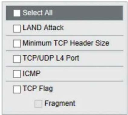
Configure packets to be dropped.
Apply
| LAND Attack | If enabled, the packets whose source IP address and destination IP address are the same will be dropped. |
| Minimum TCP Header Size | If enabled, the packets whose TCP header size is less than 20 bytes will be dropped. |
| TCP/UDP L4 Port | If enabled, the packets whose source port number and destination port number are the same will be dropped. Disable when using SNTP. |
| ICMP If enabled, the ICMP packets whose ICMP header+data is more than 512 bytes. | |
| TCP Flag | If enabled, the illegal TCP flagged packets will be dropped. This will not be applied to the fragment packets. |
| Fragment | If checked, the configuration of TCP Flag will be applied also to the fragment packets. |
Port Trunking
Configure port trunking settings.

Apply
| Trunk Mode Select a trunk mode. |
| Trunk Key Enter the key to identify the trunk group. |
| Trunk Name Enter the trunk name. |
| Member Select ports to join the trunk member. |
Notes:
• Up to 8 groups can be created in total, and up to 8 ports can be set to a group.
• The ports in the same trunk group should belong to the same VLAN.
Traffic Control
Configure storm settings. If each packet exceeds the threshold configured on this page, exceeded packets will be dropped.
| Port | Broadcast | Multicast | DLF | Ingress Bandwidth | Egress Bandwidth | ||
| 1 | Unlimited✓ | Unlimited✓ | Unlimited✓ | 10000 | Mbps | 10000 | Mbps |
| 2 | Unlimited✓ | Unlimited✓ | Unlimited✓ | 10000 | Mbps | 10000 | Mbps |
| 3 | Unlimited✓ | Unlimited✓ | Unlimited✓ | 10000 | Mbps | 10000 | Mbps |
| 4 | Unlimited✓ | Unlimited✓ | Unlimited✓ | 10000 | Mbps | 10000 | Mbps |
| 5 | Unlimited✓ | Unlimited✓ | Unlimited✓ | 10000 | Mbps | 10000 | Mbps |
| 6 | Unlimited✓ | Unlimited✓ | Unlimited✓ | 10000 | Mbps | 10000 | Mbps |
| 7 | Unlimited✓ | Unlimited✓ | Unlimited✓ | 10000 | Mbps | 10000 | Mbps |
| 8 | Unlimited✓ | Unlimited✓ | Unlimited✓ | 10000 | Mbps | 10000 | Mbps |
| 9 | Unlimited✓ | Unlimited✓ | Unlimited✓ | 10000 | Mbps | 10000 | Mbps |
| 10 | Unlimited✓ | Unlimited✓ | Unlimited✓ | 10000 | Mbps | 10000 | Mbps |
| 11 | Unlimited✓ | Unlimited✓ | Unlimited✓ | 10000 | Mbps | 10000 | Mbps |
| 12 | Unlimited✓ | Unlimited✓ | Unlimited✓ | 10000 | Mbps | 10000 | Mbps |
Apply
| Broadcast Select a rate to allow passing broadcasts. | |
| Multicast Select a rate to allow passing multicasts. | |
| DLF Select a rate to allow passing DLF (destination lookup failure) unicasts. | |
| Ingress Bandwidth | Limits the bandwidth of ingress (input to the switch) speed as the configured value. |
| Egress Bandwidth | Limits the bandwidth of egress (output from the switch) speed as the configured value. |
Note: If the rate is configured based on broadcasts, multicasts, or DLF unicasts that sometimes cannot pass due to the difference in traffic, configure the minimum rate of frames for normal use.
Mirroring
Configure to monitor the traffic (copy the contents of communication from source to destination).
| Mirroring Group | Enable | Source Port | Destination Port | |||||||||||
| 1 | 2 | 3 | 4 | 5 | 6 | 7 | 8 | 9 | 10 | 11 | 12 | |||
| Mirror 1 | □ | □ | ✓ | □ | □ | □ | □ | □ | □ | □ | □ | □ | □ | 1 ✓ |
| Mirror 2 | □ | □ | □ | □ | ✓ | □ | □ | □ | □ | □ | □ | □ | □ | 3 ✓ |
Apply
| Enable Check to enable mirroring. |
| Source Port Select ports to be monitored. |
| Destination Port Select ports to monitor the traffic. |
IGMP
Status
Displays the IGMP status.
IGMP Status

Router Port Status

| IGMP Status Displays the multicast address table. |
| Router Port Status Displays the port connected to the multicast router (server). |
IGMP Settings
Configure IGMP snooping. This product is compatible with IGMP snooping v1, v2, and v3.

Apply
| IGMP Snooping | Check to enable IGMP snooping.If enabled, you can prevent the flooding of multicast packets except for the port connected to the host which joins the multicast group.Note: The addresses in the range of 224.0.0.1-224.0.0.255 will be excepted from IGMP snooping. |
| Filter Unknown Multicasts | If checked, the packets of the multicast that is not learned will be discarded except for 224.0.0.1-224.0.0.255. |
| Host Timeout Enter the host | timeout period for receiving multicast. |
| Router Port Timeout Enter the | the timeout length for the multicast router (server). |
IGMP Querier
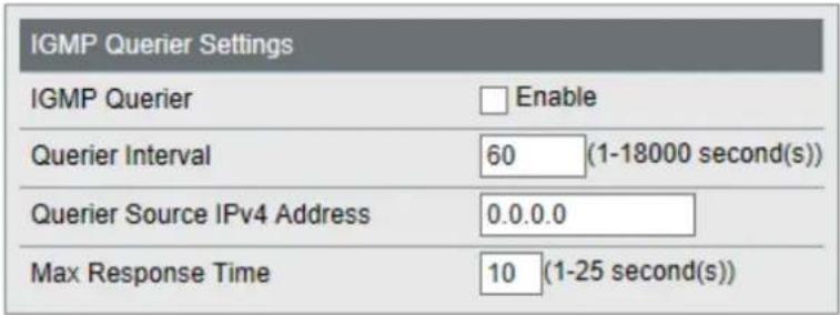
If IGMP querier is enabled, IGMP snooping can be enabled even if no multicast router is connected.
Apply
| IGMP Querier Check to enable IGMP querier. IGMP queries will be forwarded from each VLAN. | |
| Querier Interval | Configure the transmit interval for the querier that confirms the existence of multicast group's member. |
| Querier Source IPv4 Address | Enter the source IPv4 address of the querier. |
| Max Response Time | Configure the time between transmitting the querier and response from the member. If the member responds to the querier by this time, the querier determines that the member is connected. |
IGMP Router Port
Specify the port connected to the multicast router (server) for each VLAN.

| IGMP Router Port Settings | Enter the VLAN ID and specify the port connected to the multicast router (server), then click Add. |
Loop Prevention
Configure loop prevention functionality.

Apply
| Action | Configure the switch's action when a loop is detected.IgnoreWhen a loop is detected, the switch will do nothing to the port; the diag LED and loop-detected port's LED will blink for the time configured in the Disable for section. If a loop is detected again, it will continue to blink until the loop is resolved.Disable portThe switch will disable the loop-detected port for the amount of time configured in the Disable for section. At the same time, the diag LED and loop-detected port's LED will blink for the time configured in the Disable for section. If a loop is detected again after the time configured in the Disable for section has passed, the switch will disable the loop-detected port until the loop is resolved. |
| Disable for | Configure the period to disable the loop-detected port when Disable port is selected as the action. |
| Action (LDF) | Check to enable LDF loop detection method. The switch will transmit the LDF packet once per 2 seconds. If the transmitted LDF packet is received, this will assume that a loop is occurring.Note: The following are the LDF packet's source MAC addresses.BS-MP2008: 343DC4370000 (fixed value)BS-MP2012: 343DC4380000 (fixed value) |
Update Firmware
Update firmware with the local firmware file.
Click Browse and select the firmware image to update, then click Update.
Notes:
- Do not turn off the switch or close the browser while updating.
• To finish the update, reboot the switch when prompted. - Firmware cannot be updated when jumbo frame is enabled on your computer. To update firmware, disable Jumbo Frame. Refer to your computer's manual to change jumbo frame settings.
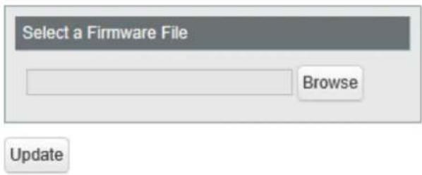
File Image Select a file image to update.
Back Up and Restore
Save or restore the switch's settings.


| Back Up Settings | Click Save to save current settings to a file. |
| Restore Settings | Click Browse to select a settings file and click Restore to start restoring.Note: To finish restoring, reboot the switch. |
Reboot
Reboot the switch.

Reboot System Click Reboot to reboot the switch.
Initialize
Restore the switch settings to the factory default.
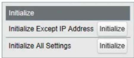
| Initialize Except IP Address | Click Initialize to initialize all settings except the switch's IPv4 address. |
| Initialize All Settings | Click Initialize to initialize all switch settings. |
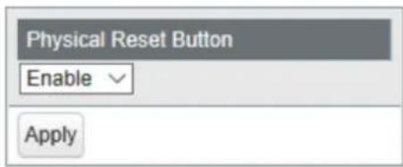
| Physical Reset Button Enable | or disable the reset button on the switch. |
Notes:
- If the physical reset button is enabled, the switch can be initialized by pressing and holding the button for 3 seconds until the diag LED turns red.
- If the physical reset button is disabled and you forgot the username or password for Settings, contact our technical support.
Statistics
Displays the switch's statistics.
Note: Each maximum value is 4,294,967,295. If this is reached or exceeded, the value will reset to 0. Rebooting the switch will also reset the value to 0.
| Port | Name | Received Octets | Received Packets | Sent Octets | Sent Packets | |||
| □ | 1 | Port 1 | 0 | 0 | 0 | 0 | Show Details | |
| □ | 2 | Port 2 | 0 | 0 | 0 | 0 | Show Details | |
| □ | 3 | Port 3 | 0 | 0 | 0 | 0 | Show Details | |
| □ | 4 | Port 4 | 0 | 0 | 0 | 0 | Show Details | |
| □ | 5 | Port 5 | 0 | 0 | 0 | 0 | Show Details | |
| □ | 6 | Port 6 | 0 | 0 | 0 | 0 | Show Details | |
| □ | 7 | Port 7 | 0 | 0 | 0 | 0 | Show Details | |
| □ | 8 | Port 8 | 0 | 0 | 0 | 0 | Show Details | |
| □ | 9 | Port 9 | 0 | 0 | 0 | 0 | Show Details | |
| □ | 10 | Port 10 | 0 | 0 | 0 | 0 | Show Details | |
| □ | 11 | Port 11 | 0 | 0 | 0 | 0 | Show Details | |
| □ | 12 | Port 12 | 629588 | 3814 | 1571654 | 2721 | Show Details |
Refresh Clear
| Name Displays the port name. |
| Received Octets Displays the number of total received octets. |
| Received Packets Displays the number of total received packets. |
| Sent Octets Displays the number of total sent octets. |
| Sent Packets Displays the number of total sent packets. |
| Show Details Click to display the detailed information. |
The following items appear when Show Detail is clicked.
| Received Octets Displays the number of total received octets. | |
| Received Unicast Packets Displays the number of received unicast packets. | |
| Received Multicast Packets | Displays the number of received multicast packets. |
| Received Broadcast Packets | Displays the number of received broadcast packets. |
| Discarded Received Packets | Displays the number of packets that the switch received but did not forwarded to any port. |
| Received Packet Error Displays the number of packets that was discarded because of FCS error. | |
| Sent Octets Displays the number of total sent octets. | |
| Sent Unicast Packets Displays the number of sent unicast packets. | |
| Sent Multicast Packets Displays the number of sent multicast packets. | |
Sent Broadcast Packets Displays the number of sent broadcast packets.
Discarded Sent Packets Displays the number of packets that could not be sent.
Notes:
- Packets that are designated to the switch (such as ping or http communication for displaying Settings) will be displayed as "Received Unicast Packets" and "Discarded Received Packets".
• The target packets of this page are MAC frames and IPv4 packets.
Network Diagnostics
Execute a communication test to the specified IP address.
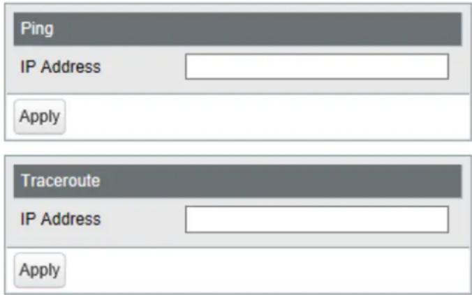
| Ping | Enter the IPv4 address and click Apply to execute a ping test to the destination. |
| Traceroute | Enter the IPv4 address and click Apply to execute a traceroute test to the destination. |
Note: To execute a traceroute test, configure the switch's default gateway.
Chapter 3 Troubleshooting
LED Is Not Lit, Abnormal Lighting or Blinking
| The power LED is not lit. | Confirm that the AC adapter or power cable is connected to the inlet. |
| The diag LED is blinking red. | If it blinks once per a second, a loop is detected. Check the cabling.If your switch has fans and its diag LED is blinking fast, a fan error may be occurring. Disconnect the power cable and reconnect it. If the LED keeps blinking, contact our technical support. |
| The link/act LED is not lit. | Confirm that the Ethernet cable is connected to both the switch and the device.Confirm that the switch and the connected device are both powered on.Confirm that the Ethernet cable type and length is compatible with the switch.Check the communication standards that the connected device is compatible with in order to check if the device can be used with the switch.If the connected device's autonegotiation can be enabled manually, enable it. Also, enable the switch's autonegotiation as well. |
| Cannot initialize with the reset button on the switch. | Confirm whether the physical reset button is enabled in Settings.If the physical reset button is disabled and you forgot the username or password of Settings, contact our technical support. |
Cannot Access Settings
• Make sure that your computer is connected to the switch.
- Access Settings with the switch's IP address (192.168.1.254 by default).
- Confirm that the username ("admin" by default) and the password ("password" by default) are correct. If you forgot the username or password, initialize the switch. To initialize the switch, press and hold the reset button for 3 seconds until the diag LED turns red.
- If a proxy server is configured for the web browser, disable the proxy server or add the switch's IP address to the proxy server's exception list.
- Confirm that your computer is connected to the port which belongs to the management VLAN.
Forgot the Username or Password
- To initialize the switch, press and hold the reset button for 3 seconds until the diag LED turns red.
- If the physical reset button is disabled and you forgot the username or password for Settings, contact our technical support.
Appendix A Specifications
Product Specifications
Refer to the quick setup guide to check the hardware specifications.
Port Specifications
Ethernet port specifications
RJ-45 with 8 pins
12345678
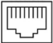
100BASE-TX
| Pin Number Signal Name Signal Function | |
| 1 RD+/TD+ Receive data (+)/Transmit data(+) | |
| 2 RD-/TD- Receive data (-)/Transmit data(-) | |
| 3 TD+/RD+ Transmit data (+)/Receive data(+) | |
| 4 (Not Use) Not used | |
| 5 (Not Use) Not used | |
| 6 TD-/RD- Transmit data (-)/Receive data (-) | |
| 7 (Not Use) Not used | |
| 8 (Not Use) Not used | |
| 10GBASE-T/5GBASE-T/2.5GBASE-T/1000BASE-T | |
| Pin Number Signal Name Signal Function | |
| 1 BI_DA+/BI_DB+ Transmit and receive data | A (+)/Transmit and receive data B (+) |
| 2 BI_DA-/BI_DB- Transmit and receive data | A (-)/Transmit and receive data B (-) |
| 3 BI_DB+/BI_DA+ Transmit and receive data | B (+)/Transmit and receive data A (+) |
| 4 BI_DC+/BI_DD+ Transmit and receive data | C (+)/Transmit and receive data D (+) |
| 5 BI_DC-/BI_DD- Transmit and receive data | C (-)/Transmit and receive data D (-) |
| 6 BI_DB-/BI_DA- Transmit and receive data | B (-)/Transmit and receive data A (-) |
| 7 BI_DD+/BI_DC+ Transmit and receive data | D (+)/Transmit and receive data C (+) |
| 8 BI_DD-/BI_DC- Transmit and receive data | D (-)/Transmit and receive data C (-) |
Factory Default Settings
| System | Switch Name BS + the switch's MAC address | ||
| Location Not defined | |||
| Contact Not defined | |||
| System IP Settings | Method of Acquiring IPv4 Address | Static IP Address | |
| IPv4 Address 192.168.1.254 | |||
| Subnet Mask 255.255.255.0 | |||
| Default Gateway 0.0.0.0 | |||
| VLAN | VLAN Settings | VLAN Mode VLAN Settings | |
| VLAN ID 1 | |||
| VLAN Name None | |||
| Management VLAN Enabled | |||
| Ports Untagged | |||
| VLAN Ports | PVID 1 | ||
| Acceptable Frame Type Admit All | |||
| Ingress Filter Enabled | |||
| Protected Port Disabled | |||
| MAC Addresses | Static MAC Filtering | Static MAC Filtering | Disabled |
| Port Settings | Speed/Mode Settings | Name | Port + port number |
| Admin | Enabled | ||
| Mode | Autonegotiation | ||
| Flow Control | Disabled | ||
| IEEE 802.3az | Enabled | ||
| APD | Disabled | ||
| Jumbo Frame | Enabled | ||
| System Security | Administration Account | Username | admin |
| Password | password | ||
| QoS | QoS Settings | QoS | Disabled |
| Schedule Method | WRR | ||
| Priority Type | CoS | ||
| QoS Mapping | Port Priority | 0 | |
| CoS Mapping | 2, 0, 1, 3, 4, 5, 6, 7 in order of CoS value | ||
| VoIP Auto Priority | VoIP Auto Priority | Disabled | |
| CoS | 7 | ||
| Security | Auto DoS Attack Prevention | LAND Attack | Disabled |
| Minimum TCP Header Size | Disabled | ||
| TCP/UDP L4 Port | Disabled | ||
| ICMP | Disabled | ||
| TCP Flag | Disabled | ||
| Fragment | Disabled | ||
| Port Trunking | Trunk Mode Manual | ||
| Trunk Key None | |||
| Trunk Name None | |||
| Member None | |||
| Traffic Control | Broadcast Unlimited | ||
| Multicast Unlimited | |||
| DLF Unlimited | |||
| Ingress Bandwidth 10000 Mbps | |||
| Egress Bandwidth 10000 Mbps | |||
| Mirroring | Enable | Mirror 1: DisabledMirror 2: Disabled | |
| Source Port | Mirror 1: 2Mirror 2: 4 | ||
| Destination Port | Mirror 1: 1Mirror 2: 3 | ||
| IGMP | IGMP Settings | IGMP Snooping Disabled | |
| Filter Unknown Multicasts Disabled | |||
| Host Timeout 260 seconds | |||
| Router Port Timeout 125 seconds | |||
| IGMP Querier | IGMP Querier Disabled | ||
| Querier Interval | 60 seconds | ||
| Querier Source IPv4 Address | 0.0.0.0 | ||
| Max Response Time | 10 seconds | ||
| IGMP Router Port | Router Ports | None | |
| Loop Prevention | Action | Disable port | |
| Disable for | 60 seconds | ||
| Action (LDF) | Disabled | ||
| Initialize | Physical Reset Button | Enable | |
Appendix B Regulatory Compliance Information
For Customers in the United States
FCC Statement
This equipment has been tested and found to comply with the limits for a Class A digital device, pursuant to part 15 of the FCC Rules. These limits are designed to provide reasonable protection against harmful interference when the equipment is operated in a commercial environment. This equipment generates, uses, and can radiate radio frequency energy and, if not installed and used in accordance with the instruction manual, may cause harmful interference to radio communications. Operation of this equipment in a residential area is likely to cause harmful interference in which case the user will be required to correct the interference at his own expense.
This device complies with Part 15 of the FCC Rules. Operation is subject to the following two conditions: (1) This device may not cause harmful interference, and (2) this device must accept any interference received, including interference that may cause undesired operation.
Only use the cables and accessories that are included in the package. Don't use other accessories or cables unless specifically instructed to in the documentation.
UL and MET
The socket-outlet shall be installed near the equipment and shall be easily accessible.
Proposition 65
WARNING:
This product and its components contain chemicals known to the State of California to cause cancer and birth defects, or reproductive harm. Wash hands after handling.
CE
CE
Dansk
This is a class A product. In a domestic environment, this product may cause radio interference, in which case the user may be required to take adequate measures.
This product may cause interference if used in residential areas. Such use must be avoided unless the user takes special measures to reduce electromagnetic emissions to prevent interference to the reception of radio and television broadcasts.
Only use the cables and accessories that are included in the package. Don't use other accessories or cables unless specifically instructed to in the documentation.
Español
The socket-outlet shall be installed near the equipment and shall be easily accessible.
Norsk
- USER MANUAL
- CONTENTS
- CHAPTER 1 INITIAL SETTINGS ....4
- CHAPTER 2 SETTINGS....16
- SECURITY 29
- PORT TRUNKING.... 30
- TRAFFIC CONTROL.... 31
- MIRRORING.... 32
- IGMP 32
- LOOP PREVENTION....35
- UPDATE FIRMWARE....36
- BACK UP AND RESTORE 36
- REBOOT.... 37
- INITIALIZE 37
- STATISTICS.... 38
- NETWORK DIAGNOSTICS....39
- CHAPTER 3 TROUBLESHOOTING....40
- LED IS NOT LIT, ABNORMAL LIGHTING OR BLINKING......40
- CANNOT ACCESS SETTINGS......40
- FORGOT THE USERNAME OR PASSWORD 40
- APPENDIX A SPECIFICATIONS......41
- APPENDIX B REGULATORY COMPLIANCE INFORMATION.....44
- CHAPTER 1 INITIAL SETTINGS
- PRODUCT REQUIREMENTS
- COMPATIBLE DEVICES AND BROWSERS
- COMPATIBLE DEVICES TO CONNECT TO BS-MP
- COMPATIBLE BROWSERS TO ENTER SETTINGS
- INSTALL BUSINESS SWITCH CONFIGURATION TOOL
- CHANGE SWITCH'S IP ADDRESS
- 5 CLICK CHANGE IP ADDRESS
- SELECT OPERATION
- 7 IF THE PASSWORD INPUT SCREEN IS DISPLAYED, ENTER "PASSWORD" AND CLICK NEXT
- 8 CLICK FINISH
- OPEN SETTINGS
- 3 CLICK NEXT TO START SEARCHING FOR THE SWITCH
- GETTING STARTED
- 4 SELECT THE SWITCH AND CLICK NEXT
- 5 CLICK SETTINGS (WEB ADMIN INTERFACE)
- 6 CLICK OK
- 7 A WEB BROWSER IS LAUNCHED AND THE LOGIN SCREEN IS DISPLAYED. ENTER "ADMIN" AS THE USERNAME AND "PASSWORD" AS THE PASSWORD, THEN CLICK LOG IN
- CHANGE USERNAME AND PASSWORD
- MAC ADDRESS LEARNING
- SVL
- IVL
- CHAPTER 2 SETTINGS
- SYSTEM INFORMATION
- SYSTEM
- SYSTEM IP SETTINGS
- VLAN SETTINGS
- VLAN PORTS
- MAC ADDRESSES
- STATIC MAC FILTERING
- PORT SETTINGS
- STATUS
- SPEED/MODE SETTINGS
- SYSTEM SECURITY
- ADMINISTRATION ACCOUNT
- QOS
- QOS SETTINGS
- QOS MAPPING
- VOIP AUTO PRIORITY
- SECURITY
- AUTO DOS ATTACK PREVENTION
- PORT TRUNKING
- NOTES
- TRAFFIC CONTROL
- MIRRORING
- IGMP
- IGMP STATUS
- ROUTER PORT STATUS
- IGMP SETTINGS
- IGMP QUERIER
- IGMP ROUTER PORT
- LOOP PREVENTION
- UPDATE FIRMWARE
- BACK UP AND RESTORE
- REBOOT
- INITIALIZE
- STATISTICS
- NETWORK DIAGNOSTICS
- CHAPTER 3 TROUBLESHOOTING
- CANNOT ACCESS SETTINGS
- FORGOT THE USERNAME OR PASSWORD
- APPENDIX A SPECIFICATIONS
- PRODUCT SPECIFICATIONS
- PORT SPECIFICATIONS
- APPENDIX B REGULATORY COMPLIANCE INFORMATION
- FOR CUSTOMERS IN THE UNITED STATES
- FCC STATEMENT
- UL AND MET
- PROPOSITION 65
- WARNING
- CE
- DANSK
- ESPAÑOL
- NORSK
Brand : BUFFALO
Model : BS-MP2012
Category : Network card