
Silhouette SPRBC052D3SS - Wine cellar DANBY - Free user manual and instructions
Find the device manual for free Silhouette SPRBC052D3SS DANBY in PDF.
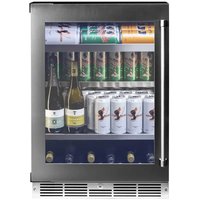


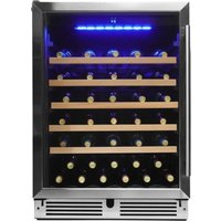
| Product Type | Wine Cellar |
| Brand | Danby |
| Model | Silhouette SPRBC052D3SS |
| Capacity | 52 bottles (standard size) |
| Temperature Zones | Dual zone, independent |
| Temperature Range | Upper zone: 5°C to 10°C, Lower zone: 10°C to 18°C |
| Cooling Type | Compressor with ventilation |
| Dimensions (H x W x D) | 86.3 cm x 58.4 cm x 66 cm |
| Net Weight | 40 kg |
| Power Supply | 120 V ~ 60 Hz |
| Energy Consumption | Approximately 0.85 kWh/24h (estimated) |
| Repairability Index | 6.5/10 (according to database) |
| Door Material | Stainless steel with insulating glass |
| Lighting Type | White LED |
| Charcoal Filter | Yes, to control odors |
| Child Safety | No (optional mechanical lock) |
| Noise Level | Approximately 42 dB(A) |
| Maintenance and Cleaning | Unplug, clean with a soft cloth and soapy water; do not use abrasive products |
| Spare Parts | Available through Danby customer service (shelves, filters, handles) |
| Warranty | Manufacturer warranty 2 years parts and labor |
Frequently Asked Questions - Silhouette SPRBC052D3SS DANBY
User questions about Silhouette SPRBC052D3SS DANBY
0 question about this device. Answer the ones you know or ask your own.
Ask a new question about this device
Download the instructions for your Wine cellar in PDF format for free! Find your manual Silhouette SPRBC052D3SS - DANBY and take your electronic device back in hand. On this page are published all the documents necessary for the use of your device. Silhouette SPRBC052D3SS by DANBY.
USER MANUAL Silhouette SPRBC052D3SS DANBY
Owner's Manual....1 - 17
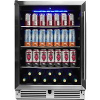
BEVERAGE CENTER
Danby Products Limited, Guelph, Ontario Canada, N1H6Z9
Danby Products Inc., Findlay, Ohio USA 45840
Welcome
Welcome to the Silhouette family. We are proud of our quality products and we believe in dependable service. We suggest that you read this owner's manual before plugging in your new appliance as it contains important operation information, safety information, troubleshooting and maintenance tips to ensure the reliability and longevity of your appliance.
Visit www.SilhouetteAppliances.com to access self service tools, FAQs and much more. For additional assistance call 1-844-455-6097.
Note the information below; you will need this information to obtain service under warranty.
You must provide the original purchase receipt to validate your warranty and receive service.
Model Number: ____
Serial Number: ____
Date of Purchase: ____
Need Help?
Before you call for service, here are a few things you can do to help us serve you better.
Read this owner's manual:
It contains instructions to help you use and maintain your appliance properly.
If you receive a damaged appliance:
Immediately contact the retailer or builder that sold you the appliance.
Save time and money:
Check the troubleshooting section at the end of this manual before calling. This section will help you solve common problems that may occur.

1-844-455-6097

Important Safety Information READ AND FOLLOW ALL SAFETY INSTRUCTIONS
SAFETY REQUIREMENTS
DANGER: Risk of fire or explosion. Flammable refrigerant used. Do not puncture refrigerant tubing.
- Do not use mechanical devices to defrost refrigerator.
- Ensure that servicing is done by factory authorized service personnel, to minimize product damage or safety issues.
- If the power supply cord is damaged, it must be replaced by the manufacturer, its service agent or similar qualified person in order to avoid hazard.
- Consult repair manual or owner's guide before attempting to service this product. All safety precautions must be followed.
- Dispose of properly in accordance with federal or local regulations. Follow handling instructions carefully.
- Do not store explosive substances such as aerosol cans with a flammable propellant in this appliance.
WARNING: Keep ventilation openings, in the appliance enclosure or in the built-in structure, clear of obstruction.
WARNING: Do not use mechanical devices or other means to accelerate the defrosting process, other than those recommended by the manufacturer.
WARNING: Do not damage the refrigerant circuit.
WARNING: Do not use electrical appliances inside the food storage compartments of the appliance, unless they are of the type recommended by the manufacturer.
CAUTION: Children should be supervised to ensure that they do not play with the appliance.
DANGER: Risk of child entrapment. Before throwing away an old appliance:
- Remove the door or lid.
- Leave shelves in place so that children may not easily climb inside.
DANGER: Do not add a lock to the door or lid. This can cause child entrapment and harm.
SAFETY REQUIREMENTS
This appliance is not intended for use by persons (including children) whose physical, sensory or mental capabilities may be different or reduced, or who lack experience or knowledge, unless such persons receive supervision or training to operate the appliance by a person responsible for their safety.
This appliance is intended to be used in household and similar applications such as:
- Staff kitchen areas in shops, offices and other working environments;
- Farm houses and by clients in hotels, motels and other residential type environments; • Bed and breakfast type environments;
- Catering and similar non-retail applications.
GROUNDING INSTRUCTIONS
This appliance must be grounded. Grounding reduces the risk of electrical shock by providing an escape wire for the electrical current.
This appliance has a cord that has a grounding wire with a 3-prong plug. The power cord must be plugged into an outlet that is properly grounded. If the outlet is a 2-prong wall outlet, it must be replaced with a properly grounded 3-prong wall outlet. The serial rating plate indicates the voltage and frequency the appliance is designed for.
WARNING - Improper use of the grounding plug can result in a risk of electric shock. Consult a qualified electrician or service agent if the grounding instructions are not completely understood, or if doubt exists as to whether the appliance is properly grounded.
Do not connect your appliance to extension cords or together with another appliance in the same wall outlet. Do not splice the power cord. Do not under any circumstances cut or remove the third ground prong from the power cord. Do not use extension cords or ungrounded (two prongs) adapters.
INSTALLATION INSTRUCTIONS
LOCATION
- Two people should be used when moving the appliance.
- Remove interior and exterior packaging prior to installation. Wipe the outside of the appliance with a soft, dry cloth and the inside with a lukewarm wet cloth.
- Place the appliance on a floor that is strong enough to support it when it is fully loaded.
- Do not place the appliance in direct sunlight or near sources of heat, such as a stove or heater, as this can increase electrical consumption. Extreme cold ambient temperatures may also cause the appliance to perform improperly.
- Do not use the appliance near water, for example in a wet basement or near a sink.
- This appliance is intended for household use only. It is not designed for outside installation, including anywhere that is not temperature controlled (garages, porches, vehicles, etc.).
- Before connecting the appliance to a power source, let it stand upright for approximately 6 hours. This will reduce the possibility of a malfunction in the cooling system from handling during transportation.
Stainless Steel model SPRBC052D3SS
- This appliance is 60.5 cm (23.8 inches) wide by 86.5 cm (34.1 inches) high by 60.3 cm (23.7 inches) deep.
Panel Ready Door model SPRBC052D3SS-P
- This appliance is 60.5 cm (23.8 inches) wide by 86.5 cm (34.1 inches) high by 60 cm (23.6 inches) deep.
IMPORTANT
Ensure that the door is fully closed when the appliance is in operation. Failure to fully close the door can lead to excessive condensation and potential water damage to flooring under the appliance. Danby will not be responsible for damages from misuse.
FRONT VENT
This appliance is front breathing. Do not block the front air vent as this will result in high operating temperatures, higher energy usage and possible system overheating and failure.

LEVELING INSTRUCTIONS
There is an adjustable leg on the bottom of the appliance that can be turned up or down to ensure that the appliance is level. It is important that the appliance is level to minimize noise and vibration. To level the appliance:
- Move the appliance to its final location.
- Turn the leveling leg counter-clockwise as far as it will go, until the top of the foot is touching the bottom of the chassis.
- Slowly turn the leveling leg clockwise until the appliance is level.

INSTALLATION INSTRUCTIONS
PREPARING THE ENCLOSURE
Gloves and safety goggles should be worn during installation.
It is not recommended to install the appliance into a corner or directly beside a wall. The door will need to be opened more than 90 degrees to allow full extension of the shelves. If it is necessary to place the unit next to a wall or in a corner, leave at least 2-4 inches (5-10 cm) of space between the wall and the appliance to allow for the door opening.
The cabinet opening must be at least 24 inches (61 cm) wide by 35 inches (88.9 cm) high by 25 inches (63.5 cm) deep.
Note: The listed depth requirement is assuming that the electrical outlet is located in the adjacent cabinetry or flush mounted in the rear wall, not surface mounted inside the enclosure.
If the electrical outlet is located inside adjacent cabinetry, cut a 1.5 inch (3.8 cm) diameter hole to admit the power cord. If the cabinet wall is metal, the hole edge must be covered with a bushing or grommet.
REQUIRED TOOLS
- Safety goggles
- Gloves
- Tape measure
- Carpenter square
- Level
- Flashlight • Electric drill with hole bit


INSTALLATION INSTRUCTIONS
ANTI-TIP BRACKET
This appliance may tip when shelves are extended, causing damage, injury or loss of contents. If this appliance is being used in a free standing application, the anti-tip bracket must be installed on either the back left or back right side of the unit.
ACCESSORIES
- Anti-tip bracket
- Bolt
- Lock Washer
- Flat Washer
- Screws
- Expansion Screws

ANTI-TIP BRACKET MOUNTING HOLES
A: Fixed mounting hole for unit B: Fixed mounting holes for drywall C: Fixed mounting holes for wood floor D: Fixed mounting holes for concrete floor E: Mounting holes on the back of the unit


INSTALLATION INSTRUCTIONS
Important: Determine the final location of the appliance before attempting to install the bracket. Choose one of the three installation methods below.

Drywall Installation:
- Place the bracket on the floor with mounting hole B against the wall.
- Use two screws to secure the bracket to the wall.
- Ensure at least one screw is secured to a wall stud.
- Place the unit so that the mounting hole E on the unit is lined up with mounting hole A on the bracket and secure with a bolt, a lock washer and a flat washer.
Note: At least one screw must enter a wood wall stud. If there are no wall studs available, use floor installation.
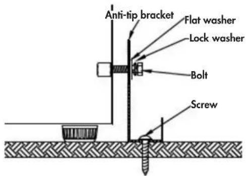
Wood Floor Installation:
- Place the bracket on the floor and secure it with two screws.
- Place the unit so that mounting hole E on the unit is aligned with mounting hole A on the bracket and secure with a bolt, a lock washer and a flat washer.

Concrete Floor Installation:
- Place the bracket on the floor and mark the location of mounting hole D on the floor.
- Using a concrete drill bit, drill an 8mm (3/8") pilot hole 45~55mm (1.7"~2") deep at the marked location.
- Remove the nut, spring washer and washer from the expansion screw.
- Carefully tap the expansion screw into the drilled hole using a hammer or mallet.
- Place the floor bracket with mounting hole D over the expansion screw and secure with the nut, spring washer and washer.
- Place the unit so that mounting hole E on the unit is aligned with mounting hole A on the bracket and secure with a bolt, lock washer and flat washer.
Important: After installing the bracket, try using light force to tip the unit. If the unit does not tip then the bracket is installed correctly. If the unit does tip, reinstall the bracket more securely.
OPERATING INSTRUCTIONS
CONTROL PANEL

- Standard mode indicator
- Energy saving mode indicator
- Sabbath mode setting
- Demo mode indicator
- Interior light colour setting indicator
- Alarm indicator
- Disable door alarm indicator
- Display panel: Shows the set temperature.
- Power indicator: Illuminates when the compressor is running.
- Temperature scale indicator
- Increase and decrease buttons: Used to increase or decrease the set temperature in 1 degree increments.
- Mode button: Press to toggle between standard and energy saving mode. The relevant indicator light will illuminate. The appliance will default to standard mode.
- Light button: Used to set the light mode.
- Power button: Press to turn the appliance on. Press and hold for 3 seconds to turn the appliance off.
OPERATING INSTRUCTIONS
INTERIOR LIGHT
The interior light will default to turning on and off when the door is opened or closed.
Press the light button once to turn the light off while the door is open. The light will resume default functioning when the door is closed.
There are four light mode settings:
- L1: Light will turn on and off when the door is opened and closed. • L2: Light will remain on indefinitely at 100% illumination.
- L3: Light will remain on for 120 minutes at 100% illumination and then resume default operation. • L4: Gallery Mode
When door is closed the control panel display will turn off. Cabinet lights will remain on 100% illumination for 120 minutes, before dimming to 50% and remain on indefinitely.
INTERIOR LIGHT COLOR
The interior light can be set to either white or blue.
- Press and hold the light button for 3 seconds until the interior light color symbol flashes.
- Press the light button to toggle between a white or blue light.
The interior light color setting indicator light will flash 5 times to confirm the change.
FUNCTION INSTRUCTION
The default temperature setting is 43°F (6°C). The default temperature scale is °F.
To switch the display between °F and °C, press and hold the Up and Down buttons simultaneously for approximately 3-5 seconds.
The temperature can be set as low as 34°F (1°C) or as high as 50°F (10°C).
Actual temperature inside the appliance can vary based on ambient temperature, how often the door is opened, and how many warm bottles have recently been added to the appliance.
If the appliance loses power, the control panel will remember the set temperature. Once power is restored, the appliance will return to normal functioning automatically.
If the inner cabinet temperature is higher than 73°F (23°C) for one hour, the error code "HI" will show on the display, the alarm indicator light will illuminate, and an alarm will sound.
If the inner cabinet temperature is lower than 28°F (-2°C), the error code "LO" will show on the display, the alarm indicator light will illuminate, and an alarm will sound.
If the inner cabinet temperature remains at 28°F (-2°C) for more than 30 minutes, the error code "CL" will show on the display, the alarm indicator light will illuminate, and an alarm will sound. The appliance will stop functioning to prevent the contents from freezing.
NOTE: If the unit is unplugged, turned off, or loses power, you must wait 3 to 5 minutes before restarting. If you attempt to restart before this time delay, the Beverage Centre will not start.
There will be a difference between the set temperature and the LED display on first use or after a longer period of disuse. After running for a short time, the temperature will revert to the set temperature.
OPERATING INSTRUCTIONS
Demo Mode: Demo mode is only intended to be used on the sales floor. It can be used to show how the appliance will look while running without engaging the compressor or the cooling function. The fan will run on low speed, but all alarms and beeping will be disabled.
Press and hold the increase button and the power button at the same time for 10 seconds to enable demo mode. The demo mode indicator light will illuminate.
Press and hold the increase button and the power button at the same time for 10 seconds to return the appliance to standard mode.
Open Door Alarm: If the door is not closed completely for 5 minutes, the alarm indicator light will illuminate and an alarm will sound.
The open door alarm can be silenced temporarily by pressing the power button once. The alarm indicator light will remain illuminated and the interior light will continue to flash until the door is closed.
If the door is closed and the alarm continues to sound, check that the actuator at the bottom of the door is making contact with the switch on the appliance.
Disable Open Door Alarm: The audible door alarm can be permanently turned off if desired. The alarm indicator light and the interior light will continue to illuminate if the door is left open for more than 5 minutes.
To disable the open door alarm, press and hold the mode button and the light button at the same time for 3 seconds until the disable door alarm indicator light illuminates. In future if the door is left open the alarm indicator light and the interior light will still flash however, the audible door alarm will not sound.
Energy Saving Mode: Energy saving mode will turn off the interior light, the control panel lights and the display. The energy saving mode indicator light will illuminate.
Pressing the increase or decrease button will cause the display to turn on for 5 seconds before resuming energy saving mode.
Sabbath Mode: Sabbath mode can be used to disable all interior lights and sounds from the appliance.
Press and hold the mode button for 5 seconds to enable Sabbath mode. The SAB symbol will illuminate and the display will show "Sb" to indicate that Sabbath mode is active.
Press and hold the mode button for 5 seconds to return the appliance to standard mode.
STORAGE INSTRUCTIONS
Shelf space provides capacity for 125 beverage cans. Lower cabinet can store wine or pop bottles, or additional cans.

OPERATING INSTRUCTIONS
SHELF INSTRUCTIONS
Do not cover shelves with aluminum foil or any other material as this will impede air flow inside the cabinet and can adversely affect the interior cabinet temperature.
To prevent damaging the door gasket, make sure to have the door opened all the way when pulling the shelves out of the rail compartment.
Removing Glass Shelf
- Pull the glass shelf forward slightly to ensure the glass notch avoids the latch, then lift the glass shelf upward to remove it.

Can Dispenser Mode
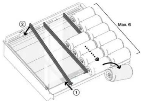
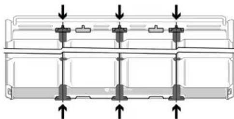
The top shelf can be converted from a conventional shelf into a can dispenser, for convenient access to grab a can without having to reach into the unit.
Tilting the Glass Shelf:
• Pull top shelf all the way out on runners. - Lift up the glass panel and slide the circular shelf supports into the second set of slots slightly further back in the metal frame sides. - Carefully rest the back edge of the glass down on the metal ledge.
Attach the Dividers:
- First hook the tabs of the divider under the front edge of the glass. Be sure to locate the tabs in the correct position.
- Locate the back tab of the divider in the correct metal slot in the back frame.
- Press the back of the divider down until it clips over the back edge of the glass.
To convert the top shelf back to a conventional flat shelf, reverse this process.
The dividers can be configured for either 4 lanes of standard 355mL (12 oz) cans, or 3 lanes of 473mL
tall cans (16 oz).
Do not load cans more than 6 deep or stacked on top of each other in the can dispenser mode.
Max capacity for the can dispenser:
- Standard 355mL cans (12 oz) x 24
- Tall 473mL cans (16 oz) x 18



OPERATING INSTRUCTIONS
DOOR REVERSAL INSTRUCTIONS MODEL SPRWC052D3SS
If the appliance is placed on its back or side for any length of time during this process, it must be allowed to remain upright for 6 hours before plugging it in to avoid damage to the internal components.
This appliance has the capability of the door opening from either the left or right side. The appliance is delivered to you with the door opening from the left side. Should you desire to reverse the opening direction, please follow the instructions below.
- Open the door at 90 degrees, release the decorative nail on the left side. See figure 1.
- Fix the screw, please don't fasten the screws. See figure 2.
- Release all the screws for the upper hinge and lower hinge, remove the hinge cover covers for both upper and lower door hinges. Install the upper door hinge cover (7) at the bottom left corner. See figures 3 & 4.
- Remove the decorative cover and lock hook on the upper and lower door frame respectively. Install the lock hook on the upper door frame and the decorative cover on the lower door frame. See figure 1 & 4.
- Rotate the door 180 degrees, insert the upper/lower hinge into the screws, see figure 2. Reattach the previously removed lower door hinge cover (8) to the top left corner, then fix the screws. Affix the decorative nail on the right side. See figure 5.


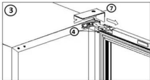

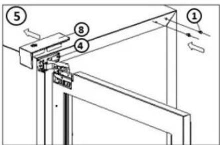
- Decorative Nail 5. Latch Hook
- Door 6. Decorative Cover
- Hinge 7. Hinge Cover Top
- Screw 8. Hinge Cover Bottom
OPERATING INSTRUCTIONS
INTEGRATED PANEL DIMENSION MODEL SPRBC052D3SS-P
Integrated Panel Dimensions are metric measurements rounded and optimized.
Due to difference in surrounding cabinetry the panel may not perfectly align with the door. The procedure below is designed to provide a finished panel that seamlessly integrates with surrounding cabinetry.
Panel Preparation: a fully integrated door panel completely covers the door frame and provides a built-in appearance.
The door panel must not weigh more than 20 Lbs (10 Kg). It is important to ensure that all drilled holes are drilled to the correct depth in order to avoid splits in the wood when hardware is installed.
- Cut the panels to the dimensions listed in the diagram below.
- Optional: Stain or finish the panel to desired stain or color. Be sure to closely follow the instructions provided by the manufacturer.
- Optional: Install handles and hardware.
The appliance will need up to 870mm (34.25 inches) to the under side of the counter to leave room for leveling adjustments.
When applying an integrated frame to a unit, ensure that both sides are finished in order to prevent warping. In some frame installations, the panel may be visible through the glass while the door is open.

OPERATING INSTRUCTIONS
HOW TO INSTALL INTEGRATED PANEL MODEL SPRBC052D3SS-P
- Fully open door.
- Starting at corner, pull gasket away from door. See Fig A.
- Continue to pull gasket free from gasket channel.
- Upon removal, lay gasket down on a flat surface.
- Secure integrated panel to door using clamps. A robust tape may also be used. It is recommended to use bar clamps to secure the panel to the door. If using tape, ensure the tape will not damage the panel finish upon removal. See Fig B.
- Using a 7/64" (3mm) drill bit, drill 6 pilot holes into the wood panel 1/2" (12mm) deep using the holes in the door frame as a guide.
NOTICE
It is important to ensure that all drill holes are drilled to the correct depth in order to avoid splits in the wood when hardwood is installed.
- Locate 6 of the ST4x 25mm screws provided with your unit.
- Using a Phillips screwdriver, place one screw into each of the 6 pilot holes and screw down. Do not over tighten the screws. See Fig C.
- Ensure the screws sit flush against the bottom of the channel. Remove clamps from the door.
NOTICE
If panel requires additional adjustment after removing clamps, slightly loosen each screw and adjust panel as necessary. Tighten screws upon completion.
- Starting at the corners, re-install the gasket into the gasket channel in the frame. Make sure the gasket is fully seated.
Fig. A
Fig. B
Fig. C

OPERATING INSTRUCTIONS
DOOR REVERSAL INSTRUCTIONS MODEL SPRBC052D3SS-P
If the appliance is placed on its back or side for any length of time during this process, it must be allowed to remain upright for 6 hours before plugging it in to avoid damage to the internal components.
This appliance has the capability of the door opening from either the left or right side. The appliance is delivered to you with the door opening from the left side. Should you desire to reverse the opening direction, please follow the instructions below.
- Open the door, unscrew the two screws (5) of the door axis (6). Move the door (7) outward and then downwards in the direction of the arrow and place the door in a safe place. See Fig A/B.
- Unscrew the two screws (10) of the top right door hinge (8), remove the top right door hinge (8) and then take out two decorative nails from the accessory bag to plug the right door hinge hole. See Fig C.
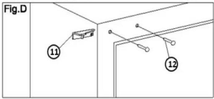
- Remove the decorative nail (12), then take out the left top hinge from the accessory bag and fix it to the upper left corner of the case with two screws. See Fig D.
- Unscrew the two screws of the bottom right hinge (2), remove the bottom right hinge (2). Take out the two decorative nails from the accessory bag to plug the hole of the bottom right hinge. See Fig A.
- Remove the decorative nail (1), then take out the bottom left hinge (15) from the accessory bag and fix it on the bottom left corner of the case with two screws. See Fig F.
- Remove the door axis of top right hinge (9) and the plate of the bottom right hinge (3) from the top right corner and the bottom right corner of the door respectively. Take out the door axis of top left hinge (13) and the plate of bottom left hinge (14) from the accessory bag, install them in the top left corner and the bottom left corner of the door respectively. See Fig A/B/E/F).
- Insert the door axis (6) removed earlier into the hole of the plate of the bottom left hinge (14), align the hole of the door axis of top left hinge (13) with the core of the top left hinge. Move the door first upward and then inward to tighten the screws of the door axis (6). See Fig E/F.
OPERATING INSTRUCTIONS


- Decorative nail
- Bottom hinge (Right)
- Plate of bottom hinge (Right)
- Screws
- Screws
- Door Axis
- Door
- Top Hinge (Right)
- Door axis of top hinge (Right)
- Screws
- Top hinge (Left)
- Decorative Nail
- Door axis of top hinge (Left)
- Plate of bottom hinge (Left)
- Bottom hinge (left)
CARE & MAINTENANCE
CLEANING
Ensure the appliance is powered off and unplugged before cleaning.
- To clean the inside of the appliance, use a soft cloth and a solution of a tablespoon of baking soda to one quart of water, or a mild soap solution, or some mild detergent.
- Wash removable shelves in a mild detergent solution, then dry and wipe with a soft cloth.
- Wring excess water out of the sponge or cloth when cleaning areas near the controls or any electrical parts.
- Clean the outside with a soft, damp cloth and some mild detergent.
- It is important to keep the area clean where the door seals against the cabinet. Clean this area with a soapy cloth. Rinse with a damp cloth and let dry.
Note: Do not use cleaners containing ammonia or alcohol on the appliance. Ammonia or alcohol can damage the appearance of the appliance. Never use any commercial or abrasive cleaners or sharp objects on any part of the appliance.
POWER FAILURE
Most power failures are corrected within a few hours and should not affect the temperature of your appliance if you minimize the number of times the door is opened. If the power is going to be off for a longer period of time, take the proper steps to protect your contents.
Note: Wait 3 to 5 minutes before attempting to restart the appliance if operation has been interrupted.
ERROR CODES
If the "HI", "LO" or "CL" error codes appear on the display for more than 5 minutes, a power reset may rectify the issue. Unplug the appliance, wait 5 minutes and then plug the unit back in. If the error code persists after a power reset, contact consumer care or an authorized service agent.
DEFROST
This unit is equipped with an automatic defrost function and does not require manual defrosting. Defrost water from the appliance is channeled into a drip tray located above the compressor. Heat transfer from the compressor causes the defrost water to evaporate.
VACATION
- Short vacations: Leave the appliance operating during vacations of less than three weeks.
- Long vacations: If the appliance will not be used for several months, remove all items and turn off the appliance. Clean and dry the interior thoroughly. To prevent odor and mold growth, leave the door open slightly, blocking it open if necessary.
MOVING
• Make sure the appliance is empty. - Secure the shelves with tape. - Secure the door with tape. - Turn the adjustable foot up to the base to avoid damage. - Protect the outside of the appliance with a blanket or similar item. - Be sure the appliance stays in the upright position during transportation. - If the appliance is placed on its back or side during transportation, upon reaching the destination, allow it to remain upright for 6 hours before plugging in to avoid damage to internal components.
DISPOSAL
This appliance may not be treated as regular household waste, it should be taken to the appropriate waste collection point for recycling of electrical components. For information on local waste collection points, contact your local waste removal agency or government office.
TROUBLESHOOTING
Silhouette Consumer Care: 1-844-455-6097
Hours of operation:
Monday to Thursday 8:30 am - 6:00 pm Eastern Standard Time
Friday 8:30 am - 4:00 pm Eastern Standard Time
Information in this manual is subject to change without notice.
PROBLEM POSSIBLE CAUSE
| Does not operate • A fuse may be blown or the circuit breaker tripped• Plug not fully inserted into the wall outlet |
| Internal temperature not cold enoughAppliance runs continuouslyAlarm sounding and “HI” on the display panel |
| Turns on and off frequently • Door is not shut properly or opened excessivelyOverload of cabinetClose proximity to heat source or direct sunlightAmbient temperature is hotter than normal |
| Light does not work • Bulb has burned out• Light button is “OFF” |
| Vibrations/Noisy • Unit is not level• Refrigerant moving within system can cause a gurgling noise. This is normal |
| Condensation on the cabinet or door • Door is not shut properly or opened excessivelyAmbient temperature or humidity is very high |
| Alarm sounding and “LO” or “CL” on the display panel• Ambient temperature is excessively lowSensor failureEvaporator temperature is too low |

SILHOUETTE
LIMITED "IN HOME" WARRANTY
This quality product is warranted to be free from manufacturer's defects in material and workmanship, provided that the unit is used under the normal operating conditions intended by the manufacturer.
This warranty is available only to the person to whom the unit was originally sold by Danby Products Limited (Canada) or Danby Products Inc. (U.S.A.) (hereafter "Danby") or by an authorized distributor of Danby, and is non-transferable.
TERMS OF WARRANTY
Plastic parts are warranted for thirty (30) days from the date of purchase, with no extensions provided.
First 24 months During the first twenty four (24) months, any functional parts of this product found to be defective, will be repaired or replaced, at warrantor's option, at no charge to the original purchaser.
To obtain service Contact the dealer where the unit was purchased, or contact the nearest authorized Danby service depot, where service must be performed by a qualified service technician. If service is performed on the unit by anyone other than an authorized service depot, all obligations of Danby under this warranty shall be void.
Boundaries of in-home service Danby reserves the right to limit the boundaries of "In Home Service" to the proximity of an authorized service depot. Any appliance requiring service outside the limited boundaries of "In Home Service", will be the consumer's responsibility to transport at their own expense to the original point of purchase or a service depot for repair. If the appliance is installed in a location that is 100 kilometers (62 miles) or more from the nearest service center, it must be delivered to the nearest authorized Danby Service Depot by the purchaser.
Transportation charges to and from the service location are not protected by this warranty and are the responsibility of the purchaser.
Nothing within this warranty shall imply that Danby will be responsible or liable for any spoilage or damage to food or other contents of this appliance, whether due to any defect of the appliance, or its use, whether proper or improper.
EXCLUSIONS
Save as herein provided, by Danby, there are no other warranties, conditions, representations or guarantees, express or implied, made or intended by Danby or its authorized distributors and all other warranties, conditions, representations or guarantees, including any warranties, conditions, representations or guarantees under any Sale of Goods Act or like legislation or statute is hereby expressly excluded. Save as herein provided, Danby shall not be responsible for any damages to persons or property, including the unit itself, howsoever caused or any consequential damages arising from the malfunction of the unit and by the purchase of the unit, the purchaser does hereby agree to indemnify and hold harmless Danby from any claim for damages to persons or property caused by the unit.
GENERAL PROVISIONS
No warranty or insurance herein contained or set out shall apply when damage or repair is caused by any of the following:
1) Power failure. 2) Damage in transit or when moving the appliance. 3) Improper power supply such as low voltage, defective house wiring or inadequate fuses. 4) Accident, alteration, abuse or misuse of the appliance such as inadequate air circulation in the room or abnormal operating conditions (i.e. extremely high or low room temperature). 5) Use for commercial or industrial purposes (i.e. If the appliance is not installed in a domestic residence). 6) Fire, water damage, theft, war, riot, hostility, acts of God such as hurricanes, floods etc. 7) Service calls resulting in customer education. 8) Improper Installation (ie. Building-in of a free standing appliance or using an appliance outdoors that is not approved for outdoor application, including but not limited to: garages, patios, porches or anywhere that is not properly insulated or climate controlled).
Proof of purchase date will be required for warranty claims; retain bills of sale. In the event that warranty service is required, present the proof of purchase to our authorized service depot.
Warranty Service
In Home
Danby Products Limited
PO Box 1778, Guelph, Ontario, Canada NIH 629
Telephone: (519) 837-0920 FAX: (519) 837-0449
1-844-455-6097
04/17
Danby Products Inc
PO Box 669, Findlay, Ohio, U.S.A. 45840
Telephone: (419) 425-8627 FAX: (419) 425-8629
Welcome
1-844-455-6097

LEVEL INSTRUCTIONS
INSTALLATION INSTRUCTIONS
PREPARE THE ENCLOSURE
INSTALLATION INSTRUCTIONS
The temperature can be set as low as 34°F (1°C) or as high as 50°F (10°C).
There will be a difference between the set temperature and the LED display on first use or after a longer period of disuse. After running for a short time, the temperature will revert to the set temperature.


USING THE APPLIANCE
DOOR REVERSAL INSTRUCTIONS MODEL SPRWC052D3SS
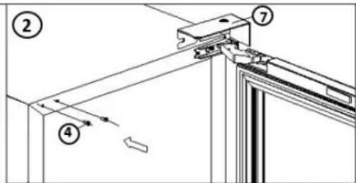


Fig. B
Fig. C

USING THE APPLIANCE
DOOR REVERSAL INSTRUCTIONS MODEL SPRBC052D3SS-P


Danby Products Limited
PO Box 1778, Guelph, Ontario, Canada N1H 6Z9




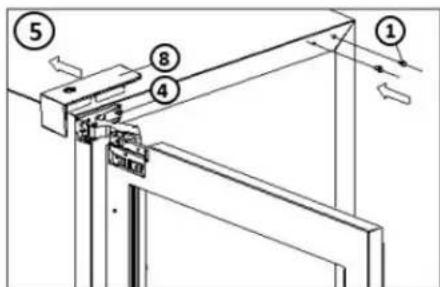
- Decorative screw 5. Handle catch
- Door 6. Decorative cover
- Hinge 7. Top hinge cover
- Screw 8. Bottom hinge cover
Fig. B
Fig. C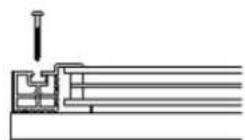




Danby Products Limited
PO Box 1778, Guelph, Ontario, Canada N1H 6Z9
Telephone: (519) 837-0920 FAX: (519) 837-0449
1-844-455-6097
04/17
Danby Products Inc.
PO Box 669, Findlay, Ohio, U.S.A. 45840
Telephone: (419) 425-8627 FAX: (419) 425-8629

SILHOUETTE
Danby Products Limited, Guelph, Ontario Canada, N1H6Z9
Danby Products Inc., Findlay, Ohio USA 45840

- WELCOME
- NEED HELP
- READ THIS OWNER'S MANUAL
- IF YOU RECEIVE A DAMAGED APPLIANCE
- SAVE TIME AND MONEY
- IMPORTANT SAFETY INFORMATION READ AND FOLLOW ALL SAFETY INSTRUCTIONS
- SAFETY REQUIREMENTS
- GROUNDING INSTRUCTIONS
- INSTALLATION INSTRUCTIONS
- LOCATION
- STAINLESS STEEL MODEL SPRBC052D3SS
- PANEL READY DOOR MODEL SPRBC052D3SS-P
- IMPORTANT
- FRONT VENT
- LEVELING INSTRUCTIONS
- PREPARING THE ENCLOSURE
- REQUIRED TOOLS
- ANTI-TIP BRACKET
- ACCESSORIES
- ANTI-TIP BRACKET MOUNTING HOLES
- DRYWALL INSTALLATION
- WOOD FLOOR INSTALLATION
- CONCRETE FLOOR INSTALLATION
- OPERATING INSTRUCTIONS
- CONTROL PANEL
- INTERIOR LIGHT
- INTERIOR LIGHT COLOR
- FUNCTION INSTRUCTION
- STORAGE INSTRUCTIONS
- SHELF INSTRUCTIONS
- REMOVING GLASS SHELF
- CAN DISPENSER MODE
- DOOR REVERSAL INSTRUCTIONS MODEL SPRWC052D3SS
- INTEGRATED PANEL DIMENSION MODEL SPRBC052D3SS-P
- HOW TO INSTALL INTEGRATED PANEL MODEL SPRBC052D3SS-P
- NOTICE
- DOOR REVERSAL INSTRUCTIONS MODEL SPRBC052D3SS-P
- CARE & MAINTENANCE
- CLEANING
- POWER FAILURE
- ERROR CODES
- DEFROST
- VACATION
- MOVING
- DISPOSAL
- TROUBLESHOOTING
- SILHOUETTE CONSUMER CARE
- HOURS OF OPERATION
- SILHOUETTE
- LIMITED "IN HOME" WARRANTY
- TERMS OF WARRANTY
- EXCLUSIONS
- GENERAL PROVISIONS
- WARRANTY SERVICE
- IN HOME
- LEVEL INSTRUCTIONS
- PREPARE THE ENCLOSURE
- USING THE APPLIANCE
Brand : DANBY
Model : Silhouette SPRBC052D3SS
Category : Wine cellar