
60987 - Digital decoder Märklin - Free user manual and instructions
Find the device manual for free 60987 Märklin in PDF.


| Product Type | Digital decoder for model trains |
| Brand | Märklin |
| Model | 60987 |
| Dimensions (L x W x H) | 26 x 16 x 8 mm |
| Weight | 10 g |
| Power supply | 16 V~, DC or AC current |
| Max. motor current | 1.0 A |
| Number of functions | 4 functions (F1-F4) |
| Communication protocol | Märklin Digital (M4), DCC compatible |
| Feedback | Yes, via track bus |
| Programming | Via command station or programmer |
| Operating temperature | 0 °C to 50 °C |
| Maintenance and cleaning | Dust with a dry brush; avoid moisture |
| Safety instructions | Do not expose to moisture; use only with a Märklin command station |
| Spare parts and repairability | Repair by an authorized Märklin service; parts available |
| Package contents | Decoder, manual |
| Warranty | 2 years |
Frequently Asked Questions - 60987 Märklin
User questions about 60987 Märklin
0 question about this device. Answer the ones you know or ask your own.
Ask a new question about this device
Download the instructions for your Digital decoder in PDF format for free! Find your manual 60987 - Märklin and take your electronic device back in hand. On this page are published all the documents necessary for the use of your device. 60987 by Märklin.
USER MANUAL 60987 Märklin
60985 Conversion Decoder Set for a Steam Locomotive
60986 Conversion Decoder Set for a Diesel Locomotive
60987 Conversion Decoder Set for a Electric Locomotive

Table of Contents Page
Using the Product as Intended 26
Contents 26
Safety Notes 26
Technical Information 26
Functions 26
Decoder Installation 27
Physical Functions 33
Logic Functions 33
Decoder functions and CV settings 33
Controllable Functions 34
Volume settings 37
CV Table for fx (MM) 38
CV Table for DCC 42
Troubleshooting Problems 47
Disposing 47
Warranty 47
My personal decoder settings 25
Using the Product as Intended
The 60985/60986/60987 decoders are for converting Märklin/Trix H0 locomotives to digital.
! Not suitable for motors with fi eld-wound coils. Locomotives with these motors must be converted with the appropriate motor retrofi t kits, item numbers 60941, 60943, or 60944.
Contents as Delivered
1 decoder
1 circuit board with a 8-pin connector (NEM)
1 speaker small
1 speaker big
1 Adhesive pad
Installation instructions
Warranty card
Tools also needed for the installation procedure include: regular and cross-point screwdrivers, tweezers, and soldering station with a maximum soldering temperature of up to 30 watts / 400°Celsius / 752°Fahrenheit with a fi ne tip, soldering fl ux for electronics (0.5 - 1 mm / 0.02" - 0.04" diameter), de-soldering braid or a de-soldering pump.
Safety Notes
- WARNING! Sharp edges and points required for operation.
- Do wiring and assembly work only on a voltage-free or grounded work mat. Failure to do this can lead to dangerous static charge from your body and to damage to the components.
- Operate the decoder only with the authorized voltage (see technical data).

There is a danger of burning yourself when working with a soldering station.
Technical Information
• Continuous current load at the motor output ≤ 1.1 amps
- Current load at the light outputs ≤ 250 milliamps
- Current load at AUX 1 - AUX 4 each ≤ 250 milliamps
- Current load at AUX 3 - AUX4 (logical output) —
- Current load AUX + light ≤ 300 milliamps
- Current load for motor and AUX 5/6 ≤ 1.1 amps
• Maximum total load ≤ 1.6 amps
• Maximum voltage ≤ 40 volts
• Sound performance (at 4 Ω /8 Ω) 2.75 watts / 1.6 watts
- Short circuit and overload protection at the outputs lights front (LV), lights rear (LH), AUX 1 – AUX 4 and at the motor outputs.
Functions
The mSD SoundDecoder is a sound decoder with very extensive setting and adaptation possibilities. Additional sound functions are available. This decoder can be updated. An appropriate control device is required for this (60213/60214/60215 Central Station CS2 with software version 4.0 or higher, 60216/60226 CS3 and/or 60971 Programmer).
The settings and digital functions can only be used in digital operation. However, the same possibilities are not available in all protocols.
These instructions describe the installation and the possible settings for the 60985,90976 and 60987 decoders. Unless otherwise stated, the functions refer to both decoders.
- Capable of multi-protocols (fx (MM), mfx, DCC, and AC/DC).
- Automatic system recognition. The address assigned to each system must be used for operation.
- Acceleration and braking delay can be set separately from each other. Any function button desired can be assigned using the function mapping.
- Typical sound backdrops for diesel and electric locomotives are included.
- Variable motor feedback control is available in digital as well as in analog operation.
- 6090, 60901, DC, and can motors with bell-shaped armatures are supported. With Sine motors, the values in CV 52 must be set to 1, in CV 56 to 0 (see CV table). Set CV 51 either to 24 or 0. In addition, you must map Aux 3 and Aux 4 respectively for Status (S) and Running (F) with the Central Station or the 60971 Programmer.
- Function mapping included. See Help in the Central Station (60213/60214/60215/60216/60226) or a detailed table to function mapping can be found on the Internet at: http://www.maerklin.de/de/service/technische-informationen
- This unit can be updated with the 60213/60214/60215 CS2 (software version 4.0 or higher), the 60216/60226 CS3, or with the 60971 Programmer.
- Programming on the Main (PoM) this type of programming must be supported by the controller. Please note the instructions for your controller when doing this.
- Switching range can be set.
- Braking / signal stopping block recognition is available in digital operation.
• Automatic calibration of a locomotive with CV 7 (mfx, DCC, MM).
Decoder Installation
The locomotive must be checked before installing the decoder to make sure that it (locomotive) is in good mechanical and electrical condition. There are situations when the locomotive will have to be repaired before installing the decoder.
First unsolder the wires to the current pickups (pickup shoe(s)), motor, and the lights. After that remove the old decoder or reverse unit. Screw down the circuit board retainer and solder the wires to the motor connections, pickup(s), and any functions.
The colors for the wires correspond to the NEM; see Page 28 for a comparison table for Märklin Standard.
If the lights are grounded to the locomotive's or powered rail car's ground on the frame, we recommend that the lights be insulated from the locomotive ground. To do this, use the E604180 plug-in bulb holder(s) and E610080 light bulb(s). This will give you flicker-free lighting.
If your locomotive or powered rail car is equipped with LED lighting, then series resistors must absolutely be installed. Series resistors differ according to the current the design. Find out the correct values for your LEDs. You may have to ask your specialty dealer about this.
If you want to retrofit your locomotive or powered rail car with LEDs, the cathodes (-) on the LED are connected to the light output on the decoder. Don't forget series resistors! The anodes (+) are connected to the common wire (orange).
The common ground return (orange) must not be connected to the ground for the locomotive or powered rail car.
Cross Referencing the Colors for the Wires
| Description Wire Color | ||
| NEM Märklin | ||
| Motor Connection 2 | gray blue | |
| Conductor Current Pickup, Track, Left (DC) Outer (AC) | black brown | |
| Front Lights | white | gray |
| Aux 1 (physical output) | green | brown/red |
| Common Wire for Lights | blue | orange |
| Rear Lights | yellow | yellow |
| Conductor Current Pickup, Track, Right (DC) Center (AC) | red | red |
| Motor Connection 1 | orange | green |
| Speaker + | brown | white |
| Speaker - | brown | white |
| Aux 2 (physical output) | violet | brown/green |
| IN1* Sound synchronization 1 (programmer) Blue / orange marking | ||
| IN2* Sound synchronization 1 (programmer) Blue / yellow marking | ||
| GND* Decoder ground (Prgrammer) Blue / black marking | ||
| Aux 3 (physical output) | Violet / yellow marking | |
| Aux 4 (physical output) | Violet / white marking | |
* Currently used only for the programmer.
The colors for the wires correspond to the NEM 652
| gray Motor Connection 2 |
| black Conductor Current Pickup, Left |
| white Front Lights |
| green Aux 1 physical output |
| blue Common Wire for Lights |
| yellow Rear Lights |
| red Conductor Current Pickup, Right / Center |
| orange Motor Connection 1 |
| brown Speaker |
| brown Speaker |
| violet Aux 2 physical output |
| blue orange marking IN1 Sound synchronization 1 (programmer) |
| blue yellow marking IN2 Sound synchronization 2 (programmer) |
| blue black marking GND Decoder ground (Programmer) |
| violet yellow marking Aux 3 physical output |
| violet white marking Aux 4 physical output |
solder pad above

solder pad below

Locomotives or powered rail cars with NEM 8-pin connector.
Solder the wires to the correct solder pads according to the diagram above. The brown wire with the ends of speaker wire is soldered and insulated.
When installing the decoder in models with a sine motor the wires for connections Aux 3 and Aux 4 may not be used.
Insert the plug into the connector while paying attention to the positioning. Place the model, with the body left off, on the programming track and test it. If the decoder works with no problems, the body can be put on the locomotive.
This decoder can also be operated on analog layouts or areas of track that are analog. The decoder recognizes alternating current or direct current voltage (AC/DC) and automatically adapts to the analog track voltage. All functions that were set under mfx or DCC for analog operation are active (see Digital Operation).
Digital Operation
The mSD sound decoders are multi-protocol decoders. These decoders can be used under the following digital protocols: mfx, DCC, fx (MM).
The digital protocol with the most possibilities is the highest order digital protocol. The sequence of digital protocols in descending order is:
Priority 1: mfx
Priority 2: DCC
Priority 3: fx (MM)
Note: Digital protocols can influence each other. For trouble-free operation, we recommend deactivating those digital protocols not needed by using CV 50. Deactivate unneeded digital protocols at this CV if your controller supports this function.
If two or more digital protocols are recognized in the track, the decoder automatically takes on the highest order digital protocol, example: mfx/DCC; the decoder takes on the mfx digital protocol (see previous table).
Note: Please note that not all functions are possible in all digital protocols. Several settings for functions, which are supposed to be active in analog operation, can be done under mfx and DCC.
Braking / Signal Stopping Block (MM, fx, mfx)
The braking module essentially applies DC voltage to the track. If the decoder recognizes a DC voltage of this kind in the track, it brakes with the delay that has been set. If the decoder recognizes a digital protocol again, it accelerates at the speed that has been set.
If automatic recognition in braking areas is to be used, we recommend shutting the DC operation off (see CV description). In DCC operation setting the value in CV 27 to 16 or 32 (see CV table).
Automatic Calibration for All Protocols
- The type of motor must be selected (see CV 52) before calibration.
- Automatic calibration of a locomotive must be done on a suitable oval of track without obstacles (signals, grades, etc.). We recommend an oval of track with curves larger than 430 mm / 17" in radius. The locomotive is accelerated to the maximum speed and can therefore derail on smaller radius curves. Go into the locomotive configuration on the Central Station->CV->Info for automatic calibration of the locomotive. In the field Firmware version, overwrite the first digit with 77. In the protocols MM/DCC, enter CV 7 directly in the configuration mode. Overwrite the value displayed there with the number 77 and store it in the locomotive.
Enter a speed with the speed control knob. Now the locomotive starts slowly, accelerates to the fastest speed, and then stops after a short while. After that, the locomotive tries several times to start up. If the locomotive finally remains at a standstill, the calibration process has ended.
No other operations should be done during the entire process.
The calibration process can be stopped with the "Stop" button, by turning the speed control knob, by changing the direction of travel. The process must be repeated after such a termination.
If the results of the calibration process are not satisfactory, calibration can be repeated with another type of motor. The process can be repeated more than once. If the test run does not give the desired result, you can adjust individual parameters manually in the motor parameters. (MM/DCC see CV tables, mfx in Locomotive Configuration in the Central Station -> CV -> Motor). The beginning and the end of the test run is indicated by the following light symbols.
| Activated (Enter the value 77) | |
| Start of the test run(Speed Level >1) | |
| End of the test run | |
| Termination or Interruption |
Extensive information about this can be found on the Internet: http://www.maerklin.de/de/service/technische-informationen
mfx Protocol
Addresses
- No address is required; each decoder is given a one-time, unique identifier (UID).
- The decoder automatically registers itself on a Central Station or a Mobile Station with its UID.
Programming
- The characteristics can be programmed using the graphic screen on the Central Station or also partially with the Mobile Station.
- All of the Configuration Variables (CV) can be read and programmed repeatedly.
- The programming can be done either on the main track or the programming track.
- The default settings (factory settings) can be produced repeatedly.
- Function mapping: Functions can be assigned to any of the function buttons with the help of the 60212 Central Station (with limitations) and with the 60213/60214/60215/60216/60226 Central Station (See help section in the Central Station).
fx (Motorola) Protocol
Addresses
• 4 addresses (a main address and 3 consecutive addresses)
- Address range:
1 - 255 depending on the controller / central controller
- The main address can be programmed manually.
- The consecutive addresses can be turned on, turned off, set and can be programmed manually or automatically.
- All 16 functions can be controlled by means of the four addresses.
Programming
- The characteristics can be programmed for the decoder can be programmed repeatedly using the programming for the Configuration Variables (CV). Reading the CVs is not possible.
-
The CV numbers and the CV values are entered directly.
-
Program the CVs only on the programming track.
- The default settings (factory settings) can be produced repeatedly.
• 14 or 27 speed levels can be programmed. - The first four functions and the lights can always be controlled by means of the first address; additional functions can be used, depending on the consecutive addresses.
- All of the settings from the function mapping for mfx or DCC programming are taken on for fx (Motorola).
- Automatic recognition corresponding to the active additional or consecutive addresses. What is recognized is whether the function can be turned on or off continuously by means of a consecutive address. This function mapping can only be determined in the mfx or DCC protocol.
- See the CV description for the fx protocol for additional information.
DCC Protocol
Addresses
- Short address – long address – multiple unit address
- Address range:
1 - 127 for short address and multiple unit address,
1 - 10239 for long address
- Every address can be programmed manually.
- A short or a long address is selected using the CVs.
- A multiple unit address that is being used deactivates the standard address.
Programming
- The characteristics can be changed repeatedly using the Configuration Variables (CV).
- The CV numbers and the CV values are entered directly.
- The CVs can be read and programmed repeatedly. (Programming is done on the programming track.)
- The CVs can be programmed in any order desired. (Programming can be done on the main track PoM). The PoM can only be done with those designated in the CV table. Programming on the main track PoM must be supported by your central controller (Please see the description for this unit.).
- The default settings (factory settings) can be produced repeatedly.
• 14/28 or 126 speed levels can be set. - All of the functions can be controlled according to the function mapping (see CV description).
- See the CV description for the DCC protocol for additional information.
We recommend that in general programming should be done on the programming track.
Physical Functions
Each of these functions must be connected externally to the circuit board. We therefore speak of physical functions. A unique mode/effect can be assigned to each physical output (AUX / lights) in digital operation. Three CVs are available for each output for this purpose. Only one mode/effect can be set for each output. A complete table for this can be found on the Internet at:
Since these functions are only executed by software, no physical output is required for them. We therefore speak here of a logic function.
Acceleration/Braking Delay
- The acceleration and braking time can be set separately from each other.
- The logic function ABV can be assigned to any function button by using the function mapping.
Switching Range (RG)
- The switching range causes a reduction in the current speed of the locomotive. This allows a fine touch in the controlling the locomotive. The switching range can be assigned in mfx and DCC to any function button by using the function mapping.
Station Announcement
The locomotive does not go until after the announcement has ended.
Opening Doors / Closing Doors
The locomotive does not start running as long as the function "opening doors / closing doors" is active. The locomotive starts accelerating according to the ABV that has been set/activated only when the function has been deactivated and the sound has ended.
Decoder functions and CV settings
The following pages have the functions and the CVs presented in tabular form. These CVs can be given a number of settings and can be assigned to a number of function buttons.
You will find the CVs and their applications for the fx (MM) and DCC protocols in separate tables.
In the mfx protocol, you can set the CVs with ease by means of the display for the CS 2 (Software Version 4.0 and higher) / CS 3. You or your dealer may have to install an update on your 60213/60214/60215 Central Station.
We recommend following the procedures that are shown and described.
Decoder 60985
| Controllable Functions |  |  | 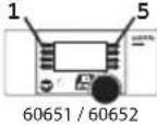 | 3 Tn 60214 / 60215 Tn 60214 / 60215 | f0 f8 f8 f0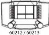 60214 / 60215 60214 / 60215 |  |
| Headlights function/off Function f0 Function f0 Function | f0 | * | ||||
| Physical function (Aux 1) | f1 | Function 1 | Function * | Function f1 | Function f1 | Function f1 |
| Sound effect: Operating sounds | f2 | Function 2 | Function * | Function f2 | Function f2 | Function f2 |
| Sound effect: Whistle blast | f3 | Function 3 | Function * | Function f3 | Function f3 | Function f3 |
| ABV off | f4 | Function 4 | Function * | Function f4 | Function f4 | Function f4 |
| Physical function (Aux 3)** | —1 | — | Function * | Function f5 | Function f5 Function f5 | Function f5 |
| Physical function (Aux 4)** | —1 | — | Function * | Function f6 | Function f6 Function f6 | Function f6 |
| Sound effect: Bell | —1 | — | Function * | Function f7 | Function f7 Function f7 | Function f7 |
| Physical function (Aux 2) | —1 | — | Function * | Function f8 | Function f8 | Function f8 |
| Sound effect: Squealing brakes off | —1 | — | — | Function f9 | Function f9 Function f9 | Function f9 |
| Sound effect: Coal being shoveled | —1 | — | — | Function f10 | Function f10 | Function f10 |
| Sound effect: Short whistle blast | —1 | — | — | Function f11 | Function f11 | Function f11 |
| Sound effect: Station announcements III | —1 | — | — | Function f12 | Function f12 | Function f12 |
| Sound effect: Rocker grate | —1 | — | — | Function f13 | Function f13 | Function f13 |
| Sound effect: Rail joints — | 1 | — | — | Function f14 | Function f14 | Function f14 |
| Sound effect: Conductor whistle | —1 | — | — | Function f15 | Function f15 | Function f15 |
** Not on sine motors
'can be controlled by using consecutive addresses
*Function and Function symbols may be displayed in different order.
Decoder 60986
| Controllable Functions | 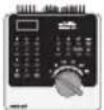 | | 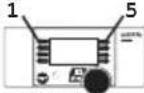 60651/60652 60651/60652 |  60653/60657Trix 66950/66955 60653/60657Trix 66950/66955 | f0 f8 f8 f0 60212/6021360214/60215 60212/6021360214/60215 |  60216/60226 60216/60226 |
| Headlights function/off Function f0 Function f0 Function | f0 | * | * | |||
| Physical function (Aux 1) | f1 | Function 1 | Function * | Function f1 | Function f1 | Function f1 |
| Sound effect: Operating sounds | f2 | Function 2 | Function * | Function f2 | Function f2 | Function f2 |
| Sound effect: Horn 1 | f3 | Function 3 | Function * | Function f3 | Function f3 | Function f3 |
| ABV switching off | f4 | Function 4 | Function * | Function f4 | Function f4 | Function f4 |
| Physical function (Aux 3)** | —1 | — | Function * | Function f5 | Function f5 Function f5 | Function f5 |
| Physical function (Aux 4)** | —1 | — | Function * | Function f6 | Function f6 Function f6 | Function f6 |
| Sound effect: Horn 2 | —1 | — | Function * | Function f7 | Function f7 Function f7 | Function f7 |
| Physical function (Aux 2) | —1 | — | Function * | Function f8 | Function f8 | Function f8 |
| Sound effect: Squealing brakes off | —1 | — | — | Function f9 | Function f9 Function f9 | Function f9 |
| Sound effect: Blower | —1 | — | — | Function f10 | Function f10 | Function f10 |
| Sound effect: Bell | —1 | — | — | Function f11 | Function f11 | Function f11 |
| Sound effect: Station announcements V | —1 | — | — | Function f12 | Function f12 | Function f12 |
| Sound effect: Auxiliary diesel | —1 | — | — | Function f13 | Function f13 | Function f13 |
| Sound effect: Rail joints | —1 | — | — | Function f14 | Function f14 | Function f14 |
| Sound effect: Conductor whistle | —1 | — | — | Function f15 | Function f15 | Function f15 |
** Not on sine motors
1 can be controlled by using consecutive addresses
*Function and Function symbols may be displayed in different order.
Decoder 60987
| Controllable Functions |  |  |  60651/60652 60651/60652 |  60653/60657Trix 66950/66955 60653/60657Trix 66950/66955 | f0 f8 f8 f0 60212/6021360214/60215 60212/6021360214/60215 |  60216/60226 60216/60226 |
| Headlights function/off Function f0 Function f0 Function | f0 | * | * | |||
| Physical function (Aux 1) | f1 | Function 1 | Function * | Function f1 | Function f1 | Function f1 |
| Sound effect: Operating sounds | f2 | Function 2 | Function * | Function f2 | Function f2 | Function f2 |
| Sound effect: Horn 1 | f3 | Function 3 | Function * | Function f3 | Function f3 | Function f3 |
| ABV switching off | f4 | Function 4 | Function * | Function f4 | Function f4 | Function f4 |
| Physical function (Aux 3)* | —1 | — | Function * | Function f5 | Function f5 Function f5 | Function f5 |
| Physical function (Aux 4)* | —1 | — | Function * | Function f6 | Function f6 Function f6 | Function f6 |
| Sound effect: Horn 2 | —1 | — | Function * | Function f7 | Function f7 Function f7 | Function f7 |
| Physical function (Aux 2) | —1 | — | Function * | Function f8 | Function f8 | Function f8 |
| Sound effect: Squealing brakes off | —1 | — | — | Function f9 | Function f9 Function f9 | Function f9 |
| Sound effect: Blower | —1 | — | — | Function f10 | Function f10 | Function f10 |
| Sound effect: Whistle blast | —1 | — | — | Function f11 | Function f11 | Function f11 |
| Sound effect: Station announcements V | —1 | — | — | Function f12 | Function f12 | Function f12 |
| Sound effect: Compressor | —1 | — | — | Function f13 | Function f13 | Function f13 |
| Sound effect: Rail joints — | 1 | — | — | Function f14 | Function f14 | Function f14 |
| Sound effect: Conductor whistle | —1 | — | — | Function f15 | Function f15 | Function f15 |
** Not on sine motors
1 can be controlled by using consecutive addresses
*Function and Function symbols may be displayed in different order.
Volume
mfx protocol: The total volume for the sound functions can be changed easily with the 60213/60214/60215/60216/60226 Central Station in the CV menu "Sound". The function mapping (assigning the function buttons) and the individual volume settings are done with the function buttons. The sound number is required for the function mapping.
fx protocol: In the fx protocol only the total volume can be changed with CV 63. It is not possible to change the individual volumes. However, settings done under mfx are preserved.
DCC protocol: To change the individual sound volume must be 31 CV changed to the value 16 and CV 32 to 0 before. The sound number is required for the function mapping and for the assignment of the CVs to the sound.
| Sound functions | Sound-Nr. | Default Values | |||||
| CV S | Steam CV Diesel CV | Electric | |||||
| Sound effect: Function f2 300 Running sounds 300 Running sounds 300 Running sounds 180 0 - 255 | |||||||
| Sound effect: Function f3 | 301 | 1 | 301 | 1 | 301 | 1 | 180 |
| Sound effect: Function f7 | 303 | 3 | 302 | 2 | 302 | 2 | 180 |
| Sound effect: Function f10 | 309 | 9 | 309 | 9 | 309 | 9 | 180 |
| Sound effect: Function f11 | 302 | 2 | 303 | 3 | 303 | 3 | 180 |
| Sound effect: Function f12 | 304 | 4 | 304 | 4 | 304 | 4 | 180 |
| Sound effect: Function f13 | 310 | 10 | 307 | 7 | 308 | 8 | 180 |
| Sound effect: Function f14 | 314 | 14 | 314 | 14 | 314 | 14 | 180 |
| Sound effect: Function f15 | 305 | 5 | 305 | 5 | 305 | 5 | 180 |
Total volume (CV63) and brake squeal (CV 146) see tables below.
CV Table for fx (MM)
| CV | Explanation Values Default Notes | |||
| 1 | Address 1 (main address) 1-255 (1 - 80)* | 60985=7860986=7260987=24 | Address is always active and is not subject to CV 49.. | |
| 2 | Minimum speed (Vmin) 1-255 (1 - 80)* | 4 | Speed at the smallest speed level. Value must be smaller than Vmax, CV 5. | |
| 3 | Acceleration delay (AV) 1-255 (1 - 80)* | 12 | CV value multiplied by 0.25 gives the time from complete stop to maximum speed. | |
| 4 | Braking delay (BV) 1-255 (1 - 80)* | 12 | CV value multiplied by 0.25 gives the time from Maximum speed to complete stop. | |
| 5 | Maximum speed (Vmax) | 1-255 (1 - 63)*{x4}* | 180 | Speed at the highest speed level. Value must be greater than CV 2. |
| 7 | Automatic Calibration | 77 | Enter Value 77. Value 77 is not stored continuously. | |
| 8 | Decoder reset (default or factory setting) 8 Val | ue is not written. | ||
| 17 | Address 3 (2nd consecutive address) 1-255 (1 | -80)* | 254 | Address can be deactivated/activated subject to CV 49. |
| 18 | Address 4 (3rd consecutive address) 1-255 (1 | -80)* | 253 | Address can be deactivated/activated subject to CV 49. |
| 27 | Braking mode:Bit 0 - 3 : always 0,Bit 4 : DC voltage, polarity against the direction of travelBit 5 : DC voltage, polarity with the direction of travelBit 6 - 7 : always | 0 - 48016320 | 48 | Braking subject to direction:- 16 normal DCC properties- 32 inverse DCC propertiesBraking not subject to direction:- 48: fx/mfx properties |
* () = 6021 Control Unit {} = the values entered are multiplied times "x" (factor).
CV Table for fx (MM)
| CV | Explanation | Values | Default | Notes |
| 29 | Configuration:Bit 0: Reverse the locomotive's direction properties0 = normal direction1 = invert directionBit 1: number of speed levelshalf levels 14 or 270 = 14 speed levels1 = 27 speed levels / half levelsBit 2: turn analog operation on/off0 = analog off, 1 = analog on | 0 - 7 | 6 | The direction properties refer to the direction of travel and the lights.The number of speed levels and half levels depend on the locomotive controller.Only digital operation or also conventional operation. Flipping back and forth between the modes is possible during operation. |
| 49 | Expanded configuration:Bit 0: number of addresses, LSBBit 1: number of addresses, MSBBit 2: automatic consecutive addressing(on / 1=off) | 0 - 7 | 5 | 0 = one | 1 = two | 0 = three | 1 = four0 Add. | 0 Add. | 1 Add. | 1 Add.0 = auto. sequence on / 1 = auto. sequence off |
| 50 | Alternative formats:Bit 0: analog AC off = 0 / analog AC one = 1Bit 1: analog DC off = 0 / analog DC on = 1Bit 2: DCC off = 0 / DCC on = 1Bit 3: mfx off = 0 / mfx on = 1 | 0 - 150 / 10 / 20 / 40 / 8 | 15 | Note:fx (Motorola) cannot deactivate itself |
| 51 | Bit 0: Motor inverted 1= on, 0 offBit 1: Light inverted 1= on, 0 offBit 2: Track inverted 1= on, 0 offBit 3: Aux 3 (1= logical, 0= amplified output)Bit 4: Aux 4 (1= logical, 0= amplified output) | 0 / 10 / 20 / 40 / 80 / 16 | 0 | The values of the required settings must be added up. |
* () = 6021 Control Unit {} = the values entered are multiplied times "x" (factor).
CV Table for fx (MM)
| CV | Explanation Values Default Notes | |||
| 52 | Motor type ... (Bit 0-4)... Auxiliary function outputs 5 and 6... Motor - Softdrive Sine... Motor - without feedback control... Motor - High efficiency propulsion C90... Motor - Bell armature... Motor - direct current DC soft... Motor - direct current DC hard... Motor - direct current DC 1 Gauge | 0 - 701234567 | 5 | Selection of a motor type for additional settings for motor feedback control.orSelection of additional function outputs on an H0 decoder.See extra table 1 for how motor outputs work as additional auxiliary functions. |
| 53 | Motor feedback control - feedback control reference | 1-255(0-63)*{x4}* | 10 | Absolute Vmax for motor characteristic |
| 54 | Motor feedback control - feedback control parameter K | 1 - 255 (0 - 63)*{x4}* | 20 | Feedback control portion K |
| 55 | Motor feedback control - feedback control parameter I | 1 - 255 (0 - 63)*{x4}* | 15 | Feedback control portion I |
| 56 | Motor feedback control - feedback control influence | 1 - 255 (0 - 63)*{x4}* | 63 | 0 = PWM without feedback control for Sine (see also CV 52 motor type) |
| 57 | Steam locomotive sound interval of the steam chuffing at speed level 1 | 1 - 255 (0 - 63)*{x4}* | 7 | without a wheel sensor |
| 58 | Steam locomotive interval of the steam chuffing starting at speed level 2, | 1 - 255 (0 - 63)*{x4}* | 22 | without a wheel sensor |
| 63 | Total volume | 1 - 255 (0 - 63)*{x4}* | 63 | Total volume for all sounds.0 = no sound |
* () = 6021 Control Unit {} = the values entered are multiplied times "x" (factor).
* An extensive table for function mapping can be found on the Internet at: http://www.maerklin.de/de/service/technische-informationen
CV Table for fx (MM)
| CV | Explanation Values Default Notes | |||
| 64 | Threshold for brake squealing | 1 - 255 (0 - 63)* {x4}* | 9 | The higher the value the sooner the squealing begins, the lower the value the later the squealing begins. If the value is too low, no squealing is activated. |
| 73 | Storing different states:Bit 0: storing function statesBit 1: storing speedBit 2: starting up with/without ABV after a reset | 0 - 70 / 10 / 20 / 4 | 7 | 0 = do not store / 1 = store0 = do not store / 2 = store0 = without ABV / 4 = with ABV |
| 74 | Storing different states:Bit 0: storing direction of travel | 0 - 1 | 10 = do | not store / 1 = store |
| 75 | Address 2 (1st consecutive address) | 1 - 80 | 60985=7960986=7360987=25 | Address can be activated/deactivated subject to CV 49. |
| 76 | Analog DC startup voltage | 1 - 63 {x4}* | 12 | Note for CS1: (140)The CS1 shows this value inverted. |
| 77 | Analog DC maximum speed | 1 - 63 {x4}* | 43 | |
| 78 | Analog AC startup voltage | 1 - 63 {x4}* | 15 | Note for CS1: (140)The CS1 shows this value inverted. |
| 79 | Analog AC maximum speed | 1 - 63 {x4}* | 49 |
* () = 6021 Control Unit {} = the values entered are multiplied times "x" (factor).
CV Table for DCC
| CV | Explanation Values Default Notes | |||
| 1 Main address 1 - 127 | 3 | Short address 1 - 127If CV 29 / Bit 5 = 0 | ||
| 2PoM | Minimum speed (Vmin) 0 - 255 | 4 | Value must be lower than Wert muss Vmax, CV 5. (see CV 67) | |
| 3PoM | Acceleration delay (AV) 0 - 255 | 12 | CV value multiplied by 0.9 gives the time from being stopped to maximum speed. | |
| 4PoM | Braking delay (BV) 0 - 255 | 12 | CV value multiplied by 0.9 gives the time from maximum speed to being stopped. | |
| 5PoM | Maximum speed (Vmax) 0 - 255 | 180 | Speed at the highest speed level.Value must be higher than Vmin, CV 2.(see also CV 94) | |
| 7 | Automatic CalibrationHersteller Versionsnummer (Softwareversion) | Enter Value 77. Value 77 is not stored continuously. | ||
| 8 | Manufacturer identification / IDDecoder reset (default or factory setting) | -8 | 131 | Read onlyValue cannot be read |
| 13PoM | Functions F1 - F8 with an alternative track signal 0 - 255 | 60985=160986=060987=0 | 0 = Func. MM or analog off1 = Func. MM or analog on[F8 F7 F6 F5 F4 F3 F2 F1] | |
| 14PoM | Functions FL, F9 - F15 with an alternative track signal 0 - 255 | 255 | 1 | 0 = Func. MM or analog off1 = Func. MM or analog on[F15 F14 F13 F12 F11 F10 F9 FL] |
| 17 Expanded address, higher value byte 192 - 231 | 192 | Long address 1 - 10239 (128) | ||
| 18 Expanded address, lower value byte 0 - 255 | 128 | If CV 29 / Bit 5 = 1 | ||
PoM ("Programming on Main") must be supported by the locomotive controller / central controller.
CV Table for DCC
| CV | Explanation Values Default Notes | |||
| 19 Multiple unit address 0 - 255 | 0 | 1 - 127 = multiple unit address0 = no multiple unit+128, Bit 7 = reverse polarity for direction when using multiple unit | ||
| 21PoM | Functions F1 - F8 when using multiple unit 0 - 255 | 0 | 0 = func. # only for locomotive address1 = func. # also for multiple unit addressBit 7-0 = [F8 F7 F6 F5 F4 F3 F2 F1] | |
| 22PoM | Functions FL, F9 - F15 when using multiple unit 0 - 255 | 0 | 0 = func. # only for locomotive address1 = func. # also for multiple unit addressBit 7-0 = [F15 F14 F13 F12 F11 F10 F9 FL] | |
| 27PoM | Braking mode:Bit 0 - 3 : always 0,Bit 4 : DC voltage, polarity against the direction of travelBit 5 : DC voltage, polarity with the direction of travelBit 6 - 7 : always 0 | 0 - 4800 / 160 / 320 | 48 | Braking subject to direction:- only Bit 4 : normal DC properties- only Bit 5 : inverse DC propertiesBraking not subject to direction:- Bit 4 + 5 : 3 rail properties |
| 29PoM | Configuration:Bit 0 : reverses direction properties of the locomotive0 = normal direction, 1 = inverse directionBit 1 : speed level 14 or select 28/1280 = 14 speed levels, 1 = 28/128 speed levelsBit 2 : turn analog operation off/on0 = analog off, 1 = analog onBit 5 : select short / long address0 = short address, 1 = long address | 0 - 390 / 10 / 20 / 40 / 32 | 6 | The direction properties refer to the direction of travel and the lights. The number of speed levels and the light bit depend on the locomotive controller.Either the short main address or the long expanded address as a locomotive address. |
PoM must be supported by the locomotive controller / central controller.
CV Table for DCC
| CV | Explanation | Values | Default Notes | This is required for advanced settings, such as CV 300 – 328. |
| 31PoM | Index high Byte 16 16 | |||
| 32PoM | Index low Byte 0 0 | |||
| 50PoM | Alternative formats:Bit 0 : Analog AC off = 0 / Analog AC on = 1Bit 1 : Analog DC off = 0 / Analog DC on = 1Bit 2 : fx (MM) off = 0 / fx (MM) on = 1Bit 3 : mfx off = 0 / mfx on = 1 | 0 - 150 / 10 / 20 / 40 / 8 | 15 | Note:DCC cannot deactivate itself. |
| 51PoM | Bit 0: Motor inverted 1= on, 0 offBit 1: Light inverted 1= on, 0 offBit 2: Track inverted 1= on, 0 offBit 3: Aux 3 (1= logical, 0= amplified output)Bit 4: Aux 4 (1= logical, 0= amplified output) | 0 / 10 / 20 / 40 / 80 / 16 | 0 | The values of the required settings must be added up. |
| 52PoM | Motor type ... (Bit 0-4)... Auxiliary – function outputs 5 and 6... Motor – Softdrive Sine... Motor – without feedback control... Motor – high-efficiency C90... Motor – bell armature... Motor – direct current DC soft... Motor – direct current DC hard... Motor – direct current DC 1 Gauge | 0 - 701234567 | 5 | Selection of a motor type for additional settings for motor feedback control orSelection of additional function outputs on an H0 decoder. See extra table* for how motor outputs work as additional auxiliary functions. |
| 53PoM | Motor feedback control – feedback control reference | 0 - 255 | 40 | Absolute Vmax for motor characteristic |
| 54PoM | Motor feedback control – feedback control parameter K | 0 - 255 | 80 | Feedback control portion K |
| 55PoM | Motor feedback control – feedback control parameter I | 0 - 255 | 60 | Feedback control portion I |
PoM must be supported by the locomotive controller / central controller.
* An extensive table for function mapping can be found on the Internet at: http://www.maerklin.de/de/service/technische-informationen
CV Table for DCC
| CV | Explanation | Values | Default Notes | |
| 56PoM | Motor feedback control – feedback control influence | 0 - 255 | 255 | 0 = PWM without feedback control for Sine (see also CV 52 motor type) |
| 57PoM | Steam locomotive sound interval of the steam chuffing at speed level 1 | 0 - 255 | 30 | |
| 58PoM | Steam locomotive interval of the steam chuffing starting at speed level 2, | 0 - 255 | 90 | |
| 63PoM | Total volume 0 - 255 | 255 | Total volume for all sounds.0 = no sound | |
| 64PoM | Brake squealing threshold 0 - 255 | 35 | The higher the value the sooner the squealing begins, the lower the value the later the squealing begins. If the value is too low, no squealing is activated.. | |
| 66PoM | Forward trim 0 - 255 | 128 | The CV value divided by 128 gives the factor with the speed level is multiplied when the locomotive is running forward. | |
| 67PoM - 94PoM | Speed table speed level 1 (Vmin) to speed table speed level 28 (Vmax) | 0 - 255 | ||
| 95PoM | Reverse trim 0 - 255 | 128 | The CV value divided by 128 gives the factor with the speed level is multiplied when the locomotive is running in reverse. | |
| 145PoM | Switching range 0 - 128 | 128 | 128 = 50% of speed level, 64 = 25% of speed level | |
| 146PoM | Sound output: Volume of squealing brakes 0 - 255 | 180 |
PoM must be supported by the locomotive controller / central controller.
CV Table for DCC
| CV | Explanation | Values | Default Notes | |
| 173PoM | Storing different states:Bit 0: Storing function statesBit 1: Storing speedBit 2: After a reset starting up with/without ABVBit 3 - 7: always 0 | 0 / 10 / 20 / 4 | 7 | 0 = do not store, value = storeIndividual values must be added. |
| 174PoM | Storing different states:Bit 0: Storing direction of travelBit 1 - 7: always 0 | 0 / 1 | 1 | 0 = do not store1 = store |
| 176PoM | Vmin Analog DC 0 - 255 | 50 | Must be smaller than CV 177 | |
| 177PoM | Vmax Analog DC 0 - 255 | 170 | Must be larger than CV 176 | |
| 178PoM | Vmin Analog AC 0 - 255 | 60 | Must be smaller than CV 179 | |
| 179PoM | Vmax Analog AC 0 - 255 | 190 | Must be larger than CV 178 | |
| CV 31 must first be set to the value 16 and CV 32 to the value 0 (see CV 31) to change the volumes (CV 300 - CV 328). | ||||
| 300PoM | Sound output: Volume of running sounds* | 0 - 255 | 180 | 0 = no sound |
| 301PoM | Sound output: Volume for Sound 1* | 0 - 255 | 180 | |
| - | up to | |||
| 328PoM | Sound output: Volume for Sound 16* | 0 - 255 | 180 | |
PoM must be supported by the locomotive controller / central controller.
* An extensive table for function mapping can be found on the Internet at: http://www.maerklin.de/de/service/technische-informationen
Troubleshooting.
When operating with different protocols you may have problems in each mode at the same time. – We recommend reducing the number of protocols. Deactivate protocols in the locomotive decoder that are not needed and also deactivate if possible protocols in the central controller that are not needed.
The locomotive jerks and falters – Check the CV setting for motor variations, change if necessary, or carry out a reset to the factory settings.
The locomotive does not run in analog. - The automatic analog recognition is deactivated and must be activated again (see CV table).
The locomotive (decoder) does not react. – Check the wiring and the solder joints, redo if necessary. Check the connector for the decoder to make sure it has permanent contact and check the way it was installed.
mfx/DCC operation: Locomotives standing on the layout start running suddenly during mfx registration. – Deactivate the automatic analog recognition on these locomotives.
The locomotive does not run. – The function "open doors / close doors" is still active. Turn off the function "close doors"; after the sound ends the locomotive will run according to the ABV that has been set.
Disposing

Products marked with a trash container with a line through it may not be disposed of at the end of their useful life in the normal household trash. They must be taken to a collection point for the recycling of electrical and electronic devices. There is a symbol on the product, the operating instructions, or the packaging to this effect. The
materials in these items can be used again according to this marking. By reusing old devices, materially recycling, or recycling in some other form of old devices such as these you make an important contribution to the protection of our environment. Please ask your city, town, community, or county authorities for the location of the appropriate disposal site.
Warranty
The warranty card included with this product specifies the warranty conditions.
- Please contact your authorized Märklin dealer for repairs or contact:
U.S. only:
Please see your authorized Märklin specialty dealer for service and repairs or contact the USA subsidiary using the contact form at www.marklin.com.
GB only:
Gebr. Märklin & Cie. GmbH Reparaturservice Stuttgarter Str. 55 - 57 73033 Göppingen Germany Tel: +49 7161 608 222 E-Mail: Service@maerklin.c


www.maerklin.com/en/imprint.html




- TABLE OF CONTENTS PAGE
- USING THE PRODUCT AS INTENDED
- CONTENTS AS DELIVERED
- SAFETY NOTES
- TECHNICAL INFORMATION
- FUNCTIONS
- DECODER INSTALLATION
- LOCOMOTIVES OR POWERED RAIL CARS WITH NEM 8-PIN CONNECTOR
- DIGITAL OPERATION
- BRAKING / SIGNAL STOPPING BLOCK (MM, FX, MFX)
- AUTOMATIC CALIBRATION FOR ALL PROTOCOLS
- NO OTHER OPERATIONS SHOULD BE DONE DURING THE ENTIRE PROCESS
- MFX PROTOCOL
- ADDRESSES
- PROGRAMMING
- FX (MOTOROLA) PROTOCOL
- DCC PROTOCOL
- PHYSICAL FUNCTIONS
- ACCELERATION/BRAKING DELAY
- SWITCHING RANGE (RG)
- STATION ANNOUNCEMENT
- OPENING DOORS / CLOSING DOORS
- DECODER FUNCTIONS AND CV SETTINGS
- VOLUME
- TROUBLESHOOTING
- DISPOSING
- WARRANTY
- U.S. ONLY
- GB ONLY
Brand : Märklin
Model : 60987
Category : Digital decoder