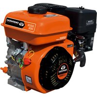
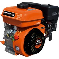
GAE168FB - Generator DAEWOO - Free user manual and instructions
Find the device manual for free GAE168FB DAEWOO in PDF.


| Product Type | Portable Generator |
| Brand | Daewoo |
| Model | GAE168FB |
| Dimensions (L x W x H) | Approx. 600 x 450 x 500 mm |
| Weight | Approx. 35 kg |
| Power Output (Rated) | Approx. 2000 W |
| Power Output (Peak) | Approx. 2500 W |
| Fuel Type | Gasoline |
| Fuel Tank Capacity | Approx. 12 L |
| Starting System | Recoil Start |
| Engine Displacement | Approx. 125 cc |
| Outlet Type | 2x 120V AC, 1x 12V DC |
| Noise Level | Approx. 70 dBA |
| Run Time (50% load) | Approx. 8 hours |
| Low Oil Shutdown | Yes |
| Fuel Gauge | Yes |
| Wheels & Handle | Yes, for portability |
| Maintenance | Regular oil changes, spark plug cleaning, air filter replacement |
| Safety Features | Automatic voltage regulator, overload protection, ground fault circuit interrupter |
| Spare Parts Availability | Contact Daewoo service centers or authorized dealers |
Frequently Asked Questions - GAE168FB DAEWOO
User questions about GAE168FB DAEWOO
0 question about this device. Answer the ones you know or ask your own.
Ask a new question about this device
Download the instructions for your Generator in PDF format for free! Find your manual GAE168FB - DAEWOO and take your electronic device back in hand. On this page are published all the documents necessary for the use of your device. GAE168FB by DAEWOO.
USER MANUAL GAE168FB DAEWOO
USER'S MANUAL
www.daewoopowerproducts.com
Manufactured under license of Daewoo International Corporation, Korea
INDEX
- SAFETY INFORMATION ...... 2
- COMPONENT & CONTROL LOCATION .... 2
- BEFORE OPERATING CHECK 2
- OPERATION 3
- MAINTENANCE....6
- TROUBLESHOOTING 13
- SPECIFICATIONS....15
- WIRING DIAGRAM 18
WARRANTY 19
1. SAFETY INFORMATION
- Understand the operation of all controls and learn how to stop the engine quickly in case of emergency.
Make sure the operator receives adequate instruction before operating the equipment. - Do not allow children to operate the engine. Keep children and pets away from the area of operation.
- Your engine's exhaust contains poisonous carbon monoxide. Do not run the engine without adequate ventilation, and never run the engine indoors.
- The engine and exhaust become very hot during operation. Keep the engine at least 1 meter (3 feet) away from buildings and other equipment during operation. Keep flammable materials away, and do not place anything on the engine while it is running.
This label warns you of potential hazards that can cause serious injury. Read it carefully. If the label comes off or becomes hard to read, contact your dealer for replacement.
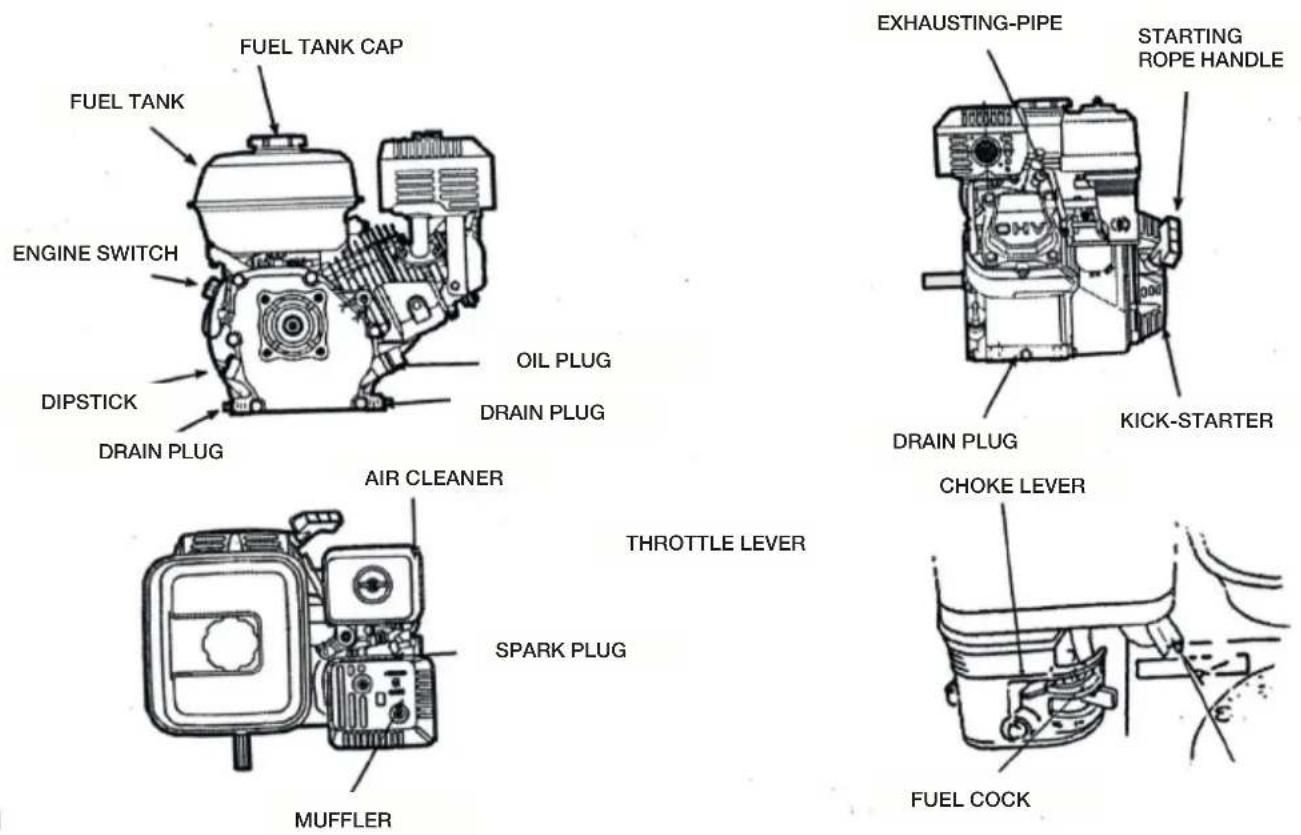
2. COMPONENT & CONTROL LOCATION
3. BEFORE OPERATION CHECKS
IS YOUR ENGINE READY TO GO?
For your safety, and to maximize the service life of your equipment, it is very important to take a few moments before you operate the engine to check its condition. Be sure to take care of any problem
you find, or have your servicing dealer correct it, before you operate the engine.
Before beginning your preoperation checks, be sure the engine is level and the engine switch is in the OFF position.
Always check the following items before you start the engine: Check the General Condition of the engine
- Look around and underneath the engine for signs of oil or gasoline leaks.
- Remove any excessive dirt or debris, especially around the muffler and recoil starter.
- Look for signs of damage.
- Check that all shields and covers are in place, and all nuts, bolts, and screws are tightened.
Check the Engine
- Check the fuel level. Starting with a full tank will help to eliminate or reduce operating interruptions for refueling.
- Check the engine oil level. Running the engine with a low oil level can cause engine damage.
The Oil Alerts system (applicable types) will automatically stop the engine before the oil level falls below safe limits. However, to avoid the inconvenience of an unexpected shutdown, always check the engine oil level before startup.
- Check the reduction case oil level on applicable types. Oil is essential to reduction case operation and long life.
- Check the air filter element. A dirty air filter element will restrict air flow to the carburetor, reducing engine performance.
- Check the equipment powered by this engine.
Review the instructions provided with the equipment powered by this engine for any precautions and procedures that should be followed before engine startup.
ELECTRIC STARTER TYPES
4. OPERATION
SAFE OPERATING PRECAUTIONS
Before operating the engine for the first time, please review the SAFETY INFORMATION section the Review the instructions provided with the equipment powered by this engine for any safety precautions that should be observed with engine startup, shutdown or operation.
STARTING THE ENGINE
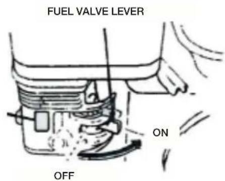
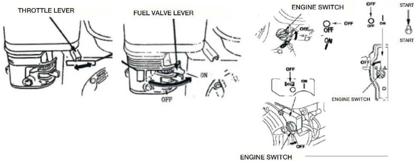
- Move the fuel valve lever to the ON position.
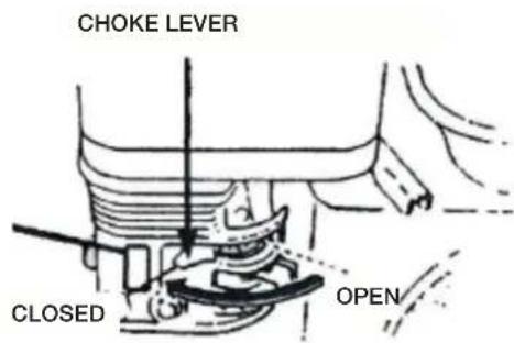
- To start a cold engine, move the choke lever to the CLOSED position.
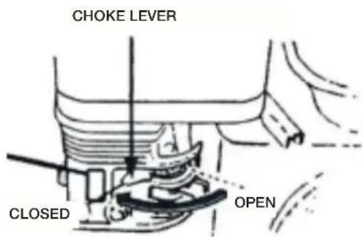
To restart a warm engine, leave the choke lever in the OPEN position.
Some engine applications use a remote-mounted choke control rather than the engine-mounted choke lever shown here. Refer to the instructions provided by the equipment manufacturer.
OPERATION
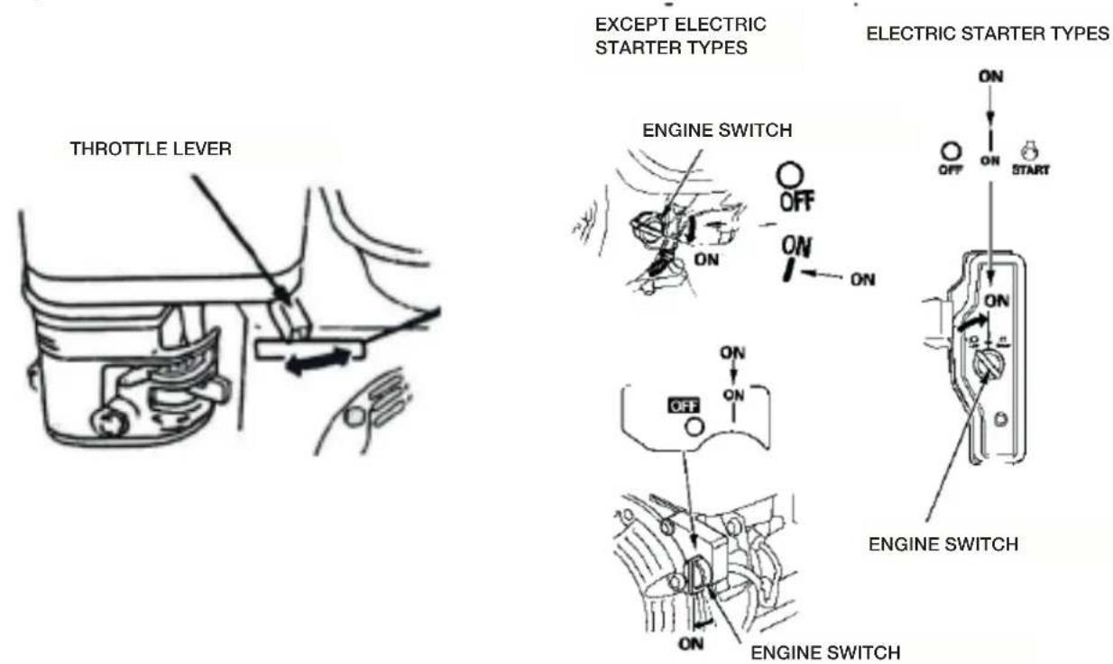
- Move the throttle lever away from the MIN. position, about 1/3 of the way toward the MAX. position. Some engine applications use a remote-mounted throttle control rather than the engine-mounted throttle lever shown here. Refer to the instructions provided by the equipment manufacturer.
- Turn the engine switch to the ON position.
- Operate the starter.
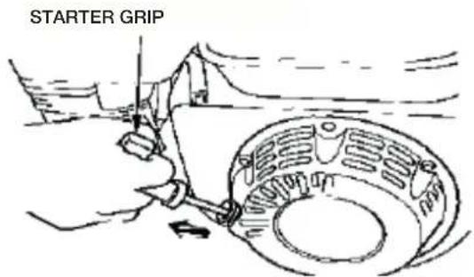
RECOIL STARTER:
Pull the starter grip lightly until you feel resistance, then pull briskly.
Return the starter grip gently.
NOTICE
Do not allow the starter grip to snap back against the engine. Return it gently to prevent damage to the starter.
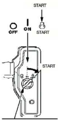
ELECTRIC STARTER (applicable types):
Turn the key to the START position, and hold it there until the engine starts.
If the engine fails to start within 5 seconds, release the key, and wait at least 10 seconds before operating the starter again.
NOTICE
Using the electric starter for more than 5 seconds at a time will overheat the starter motor and can damage it.
When the engine starts, release the key, allowing it to return to the ON position.
- If the choke lever has been moved to the CLOSED position to start the engine, gradually move it to the OPEN position as the engine warms up.
ENGINE SWITCH (applicable types)
STOPPING THE ENGINE
To stop the engine in an emergency, simply turn the engine switch to the OFF position. Under normal conditions, use following procedure. Refer to the instructions provided by the equipment manufacturer.
- Move the throttle lever to the MIN. position.
Some engine applications use a remote-mounted throttle control rather than the engine-mounted throttle lever shown here. - Turn the engine switch to the OFF position.
- Turn the fuel valve lever to the OFF position.
5. MAINTENANCE
Remember that an authorized servicing dealer knows your engine best and is fully equipped to maintain and repair it. To ensure the best quality and reliability, use only new genuine parts or their equipments for repair and replacement.
MAINTENANCE SCHEDULE
| REGULAR SERVICE PERIOD (3)ITEM Performed at every indicated Month or perating hour interval, whichever comes fist | Before each use | Fist month or 20 Hrs. | Every 3 months or 50 Hrs. | Every 6 months or 100 Hrs. | Every year or 300 Hrs. | ||
| • | Engine oil | Check level | ○ | ||||
| Change ○ | ○ | ||||||
| • | Air filter | Check | ○ | ||||
| Clean | ○(1) | ||||||
| Replace | ○* | ||||||
| • | Spark plug | Check-adjust | ○ | ||||
| Replace | ○ | ||||||
| Spark arrester | Clean | ○ | |||||
| • | Idle speed | Check-adjust | ○(2) | ||||
| • | Valve clearance | Check-adjust | ○(2) | ||||
| • | Combustion chamber | Clean | After every 500Hrs. (2) | ||||
| • | Fuel tank and filter | Clean | ○(2) | ||||
| • | Fuel tube | Check | Every 2 years (Replace if necessary) (2) | ||||
- Internal vent carburetor with dual element type only.
- Cyclone type every 6 months or 150 hours.
- Replace paper element type only.
- Cyclone type every 2 years or 600 hours.
a. Service more frequently when used in dusty areas.
b. These items should be serviced by your servicing dealer, unless you have the proper tools and are mechanically proficient. Refer to shop manual for service procedures.
c. For commercial use, b hours of operation to determine proper maintenance intervals. Failure to follow this maintenance schedule could result in non-warrantable failures.
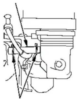
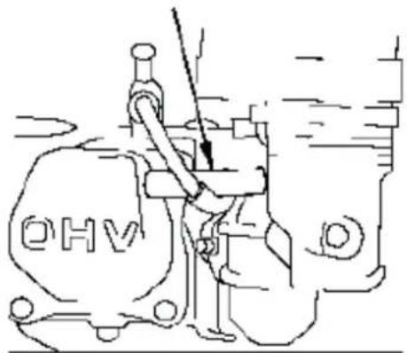
NOTICE Fuel can damage paint and some types of plastic. Be careful not to spill fuel when filling your fuel tank. Damage caused by spilled fuel is not covered under the Distributor's Limited Warranty.
Never use stale or contaminated gasoline or oil/gasoline mixture. Avoid getting dirt or water in the fuel tank.
Occasionally you may hear a light "spark knock" or "pinging" (metallic rapping noise) while operating under heavy loads. This is no cause for concern.
If spark knock or pinging occurs at a steady engine speed, under normal load, change brands of gasoline.
If spark knock or pinging persists, see an authorized servicing dealer.
NOTICE Running the engine with persistent spark knock or pinging can cause engine damage.
Running the engine with persistent spark knock or pinging is considered misuse, and the Distributor's Limited
Warranty does not cover parts damaged by misuse.
-
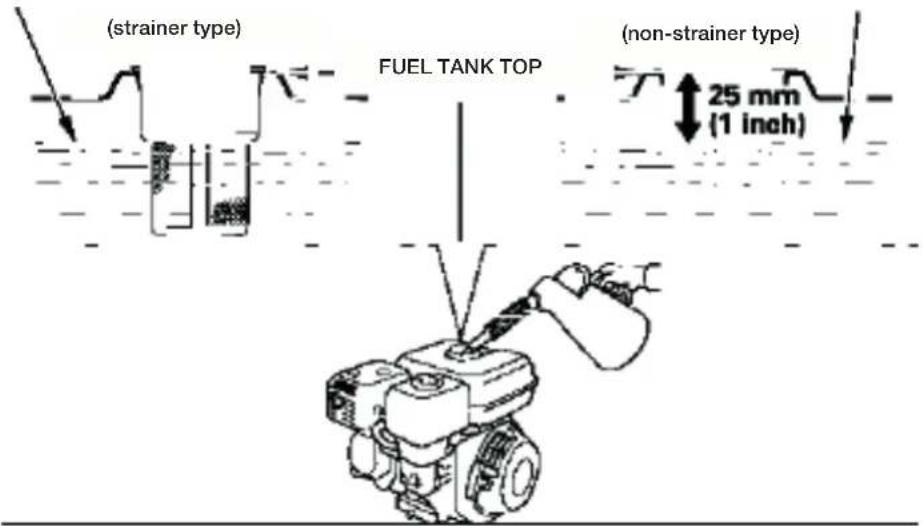
With the engine stopped and on a level surface, remove the fuel tank cap and check the fuel level. Refill the tank if the fuel level is low.
-
Add fuel to the bottom of the fuel level limit of the fuel tank. Do not overfill. Wipe up spilled fuel before starting the engine.
Oil is a major factor affecting performance and service life. Use 4-stroke automotive detergent oil. Use 4-stroke motor oil that meets or exceeds the requirements for API service classification SJ, SL, or equivalent. Always check the API service label on the oil container to be sure it includes the letters SJ, SL, or equivalent.
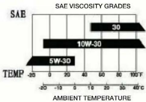
SAE 10W-30 is recommended for general use. Other viscosities shown in the chart may be used when the average temperature in your area is within the indicated range.
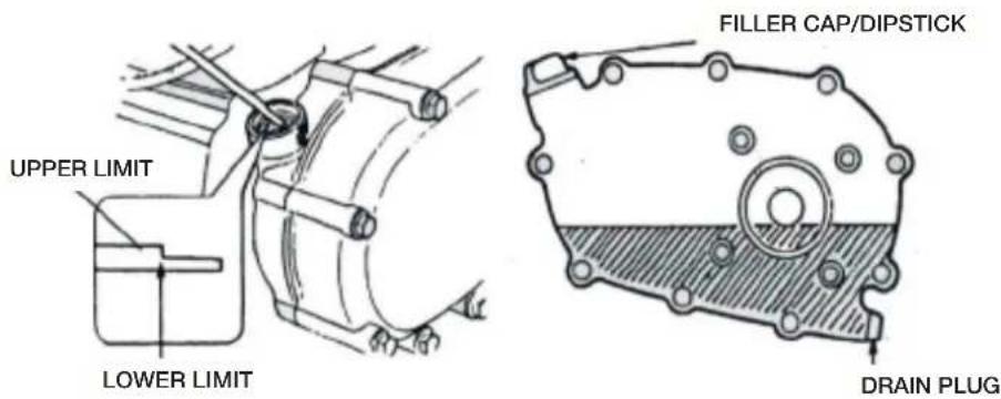
Oil Level Check
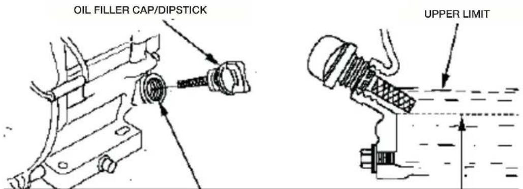
Check the engine oil level with the engine stopped and in a level position.
- Remove the oil filler cap/dipstick and wipe it clean.
- Insert the oil filler cap/dipstick into the oil filler neck as shown, but do not screw it in, then remove it to check the oil level.
- If the oil level is near or below the lower limit mark on the dipstick, fill with the recommended oil to the upper limit mark (bottom edge of the oil fill hole). Do not overfill.
- Reinstall the oil filler cap/dipstick.
NOTICE
OIL FILL HOLE
Running the engine with a low oil level can cause engine damage.
The Oil Alert® system (applicable types) will automatically stop the engine before the oil level falls below the safe limit. However, to avoid the inconvenience of an unexpected shutdown, always check the engine oil level before startup.
Oil Change
Drain the used oil when the engine is warm. Warm oil drains quickly and completely.
-
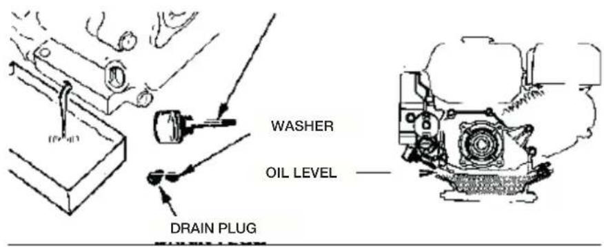
Place a suitable container below the engine to catch the used oil, then remove the oil filler cap/dipstick, oil drain plug and washer.
-
Allow the used oil to drain completely, then reinstall the oil drain plug and new washer, and tighten the oil drain plug securely.
Please dispose of used motor oil in a manner that is compatible with the environment. We suggest you take used oil in a sealed container to your local recycling center or service station for reclamation. Do not throw it in the trash, pour it on the ground, or down a drain.
- With the engine in a level position, fill to the upper limit mark (bottom edge of the oil fill hole) on the dipstick with the recommended oil.
NOTICE Running the engine with a low oil level can cause engine damage.
The Oil Alert® system (applicable types) will automatically stop the engine before the oil level falls below the safe limit. However, to avoid the inconvenience of an unexpected shutdown, fill to the upper limit, and check the oil level regularly.
- Install the oil filler cap/dipstick and tighten securely.
OIL FILLER CAP/DIPSTICK
Recommended Oil
Use the same oil that is recommended for the engine. Oil Level Check
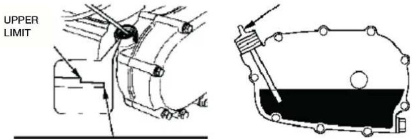
Check the reduction case oil level with the engine stopped and in a level position.
Reduction Case With Centrifugal Clutch
- Remove the oil filler cap/dipstick and wipe it clean.
- Insert and remove the oil filler cap/dipstick without screwing it into the filler hole. Check the oil level shown on the oil filler cap/ dipstick.
- If the oil level is low, add oil to reach the upper limit mark on the dipstick with the recommended oil.
- Screw in the oil filler cap/dipstick and tighten securely.
Oil Change
Drain the used oil while the engine is warm. Warm oil drains quickly and completely.
- Place a suitable container below the reduction case to catch the used oil, then remove the oil filler cap/dipstick, the drain plug and washer.
-
Allow the used oil to drain completely, then reinstall the drain plug and a new washer, and tighten it securely.
Please dispose of used motor oil in a manner that is compatible with the environment. We suggest you take used oil in a sealed container to your local recycling center or service station for reclamation.
Do not throw it in the trash or pour it on the ground or down a drain. -
With the engine in a level position, fill to the upper limit mark on the dipstick with the recommended oil. To check the oil level, insert and remove the dipstick without screwing it into the filler hole.
Reduction case oil capacity:
0.5L (0.53 US qt, 0.44 Imp qt)
NOTICE Running the engine with a low reduction case oil level can cause reduction case damage.
- Screw in the filler cap/dipstick securely.
AIR CLEANER
A dirty air cleaner will restrict air flow to the carburetor, reducing engine performance. If you operate the engine in very dusty areas, clean the air filter more often than specified in the MAINTENANCE SCHEDULE.
NOTICE Operating the engine without an air filter, or with a damaged air filter, will allow dirt to enter the engine, causing rapid engine wear. This type of damage is not covered by the Distributor's Limited Warranty.
Inspection
Remove the air cleaner cover and inspect the filter elements. Clean or replace dirty filter elements. Always replace damaged filter elements. If equipped with an oil-bath air cleaner, also check the oil level.
Refer to pages 20 for instructions that apply to the air cleaner and filter for your engine type.
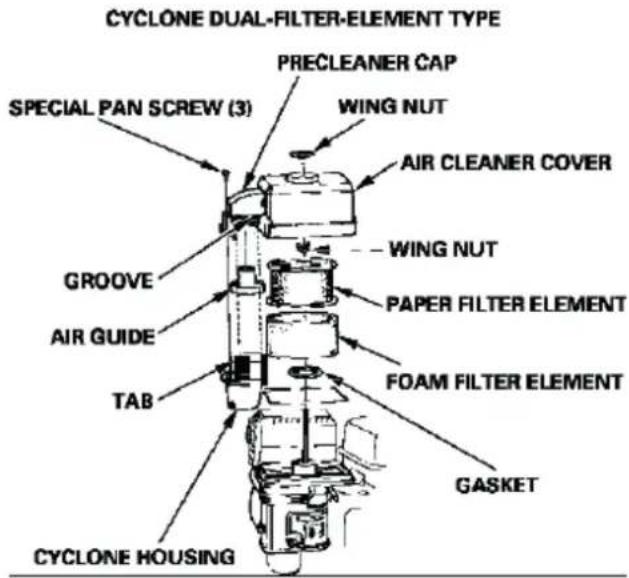
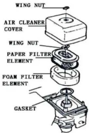
Cleaning Dual-Filter-Element Types
- Remove the wing nut from the air cleaner cover, and remove the cover.
- Remove the wing nut from the air filter, and remove the filter.
- Remove the foam filter from the paper filter.
- Inspect both air filter elements, and replace them if they are damaged. Always replace the paper air filter element at the scheduled interval.
- Clean the air filter elements if they are to be reused.
Paper air filter element: Tap the filter element several times on a hard surface to remove dirt, or blow compressed air [not exceeding 207 kPa (2.1 kgf/cm 2, 30 psi)] through the filter element from the inside.
Never try to brush off dirt; brushing will force dirt into the fibers.
Foam air filter element: Clean in warm soapy water, rinse, and allow to dry thoroughly. Or clean in nonflammable solvent and allow to dry. Dip the filter element in clean engine oil, then squeeze out all excess oil. The engine will smoke when started if too much oil is left in the foam.
- CYCLONE TYPE ONLY: Remove the three pan-head screws from the precleaner cap, then remove the cyclone housing and air guide. Wash the parts with water, dry them thoroughly, and reassemble them.
Be sure to install the air guide as shown in the illustration.
-
Install the cyclone housing so the air intake tab fits into the groove in the precleaner cap. Wipe dirt from the inside of the air cleaner case and cover, using a moist rag. Be careful to prevent dirt from entering the air duct that leads to the carburetor.
-
Place the foam air filter element over the paper element, and reinstall the assembled air filter.
Be sure the gasket is in place beneath the air filter. Tighten the air filter wing nut securely.
- Install the air cleaner cover, and tighten the wing nut securely.
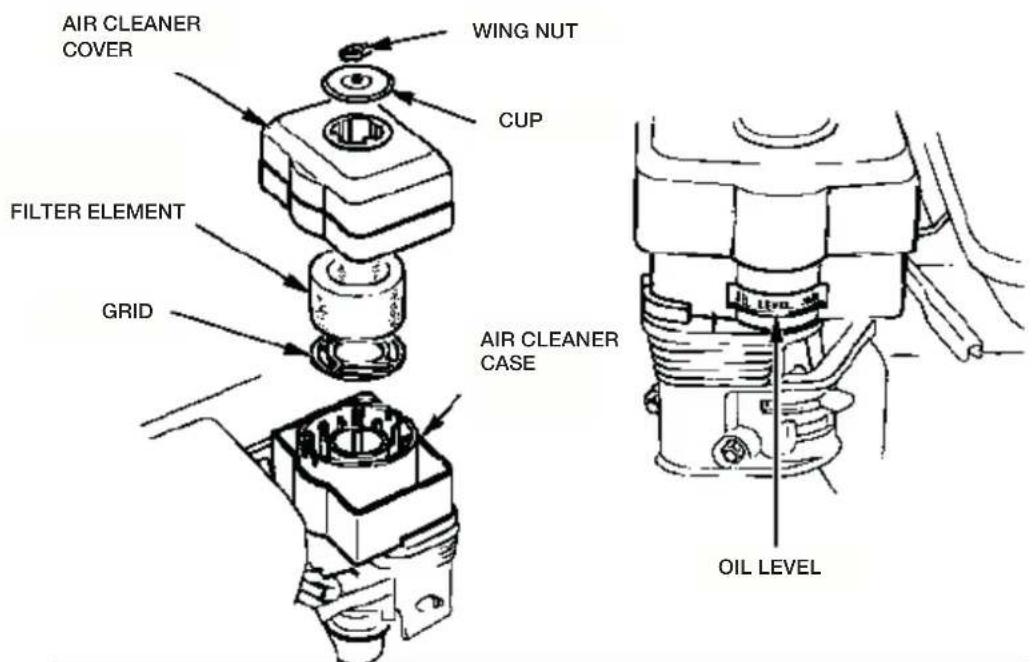
OIL-Bath Type
-
Remove the wing nut, and remove the air cleaner cap and cover.
-
Remove the air filter element from the cover. Wash the cover and filter element in warm soapy water, rinse, and allow to dry thoroughly. Or clean in nonflammable solvent and allow to dry.
-
Dip the filter element in clean engine oil, then squeeze out all excess oil. The engine will smoke if too much oil is left in the foam.
-
Empty the used oil from the air cleaner case, wash out any accumulated dirt with nonflammable solvent, and dry the case.
-
Fill the air cleaner case to the OIL LEVEL mark with the same oil that is recommended for the engine.
Oil capacity: 60 cm3 (2.0 US oz, 2.1 Imp oz)
- Reassemble the air cleaner, and tighten the wing nut
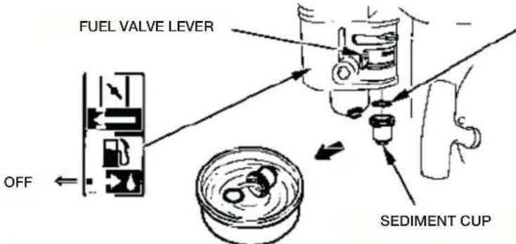
SEDIMENT CUP Cleaning
- Move the fuel valve to the OFF position, then remove the fuel sediment cup and 0-ring.
- Wash the sediment cup and 0-ring in nonflammable solvent, and dry them thoroughly.
- Place the 0-ring in the fuel valve, and install the sediment cup. Tighten the sediment cup securely.
- Move the fuel valve to the ON position, and check for leaks. Replace the 0-ring if there is any leakage.
SPARK PLUG
Recommended Spark Plugs: F7TC
The recommended spark plug is the correct heat range for normal engine operating temperatures.
NOTICE An incorrect spark plug can cause engine damage.
For good performance, the spark plug must be properly gapped and free of deposits.
- Disconnect the spark plug cap, and remove any dirt from around the spark plug area.
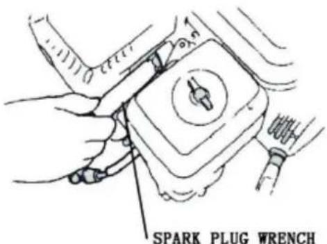
- Remove the spark plug with a 13/16-inch spark plug wrench.
- Inspect the spark plug. Replace it if damaged, badly fouled, if the sealing washer is in poor condition, or if the electrode is worn.
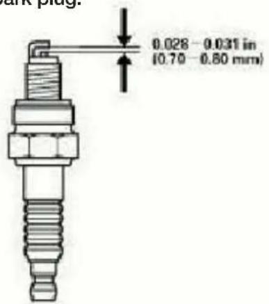
- Measure the spark plug electrode gap with a wire-type feeler gauge. Correct the gap, if necessary, by carefully bending the side electrode. The gap should be: 0.70-0.80 mm (0.028-0.031 in)
- Install the spark plug carefully, by hand, to avoid cross-threading.
- After the spark plug is seated, tighten with a 13/16-inch spark PLUG WRENCH TO AVOID CROSSTHREADING.
- When installing a new spark plug, tighten 1/2 turn after the spark plug seats to compress the washer.
- When reinstalling the original spark plug, tighten 1/8-1/4 turn after the spark plug to compress the washer.
NOTICE A loose spark plug can overheat and damage the engine. Over tightening the spark plug can damage
the threads in the cylinder head.
- Attach the spark plug cap to the spark plug.
6. THROUBLESHOOTING
WARNING
- To avoid severe burns or fire hazards, let the engine cool before transporting it or storing it indoors.
-
When transporting the engine, turn the fuel valve to the OFF position and keep the engine level to prevent fuel spillage. Fuel vapor or spilled fuel may ignite.
Before storing the unit for an extended period; -
Be sure the storage area is free of excessive humidity and dust.
-
Drain the fuel...
a. With the fuel valve OFF, remove and empty the sediment cup.
b. Turn the fuel valve ON and drain the gasoline in the fuel tank into a suitable container.
c. Replace the sediment cup and tighten securely.
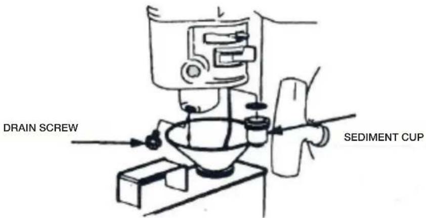
d. Drain the carburetor by loosening the drain screw. Drain the gasoline into a suitable container.
WARNING Gasoline is extremely flammable and is explosive under certain conditions.
Do not smoke or allow flames or sparks in the area.
-
Change the engine oil.
-
Remove the spark plug and pour about a tablespoon of clean engine oil into the cylinder. Crank the engine several revolutions to distribute the oil, then reinstall the spark plug.
- Pull the starter rope slowly until resistance is felt. Continue pulling until the notch on the starter pulley aligns with the hole on the recoil starter (see illustration below). At this point, the intake and exhaust valves are closed, and this will help to protect the engine from internal corrosion.
6.QAE type: Remove the battery and store it in a cool, dry place. Recharge it once a month.
7.Cover the engine to keep out dust.
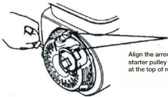
Align the arrow on the starter pulley with the hole at the top of recoil starter.
Engine will not start, using recoil starter:
- Is the engine switch ON?
- Does the oil alert lamp flash when the starter is operated?
- Is the fuel valve ON?
- Is there fuel in the fuel tank?
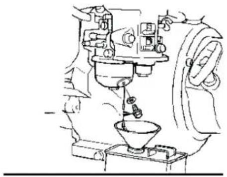
- Is gasoline reaching the carburetor?
To check, loosen the drain screw with the fuel valve on.
WARNING If any fuel is spilled, make sure the area is dry before testing the spark plug or starting the engine.
Fuel vapor or spilled fuel may ignite.
DRAIN SCREW
THROUBLESHOOTING
- Is there a spark at the spark plug?
a. Remove the spark plug cap. Clean any dirt from around the spark plug base, then remove the spark plug.
b. Install the spark plug in the plug cap.
c. Turn the engine switch on.
d. Grounding the side electrode to any engine ground, and pull the recoil starter to see if sparks jump across the gap.
e. If there is no spark, replace the plug.
If OK, try to start the engine according to the instructions.
- If the engine still does not start, take the engine to the dealer.
Engine will not start, using electric starter:
-
Are the battery cables securely connected and free of corrosion?
-
Is the battery fully charged?
NOTE: If the engine does not charge the battery, check the circuit breaker.
- If the starter motor operates but the engine will not start, follow the troubleshooting procedures described under recoil starter operation.
7. SPECIFICATIONS
Model: GAE152F
Max power output: 2.5 hp (1.2 kW) / 3600 rpm
Bore stroke: 52 x 46 mm
Displacement: 98 cc
Compression ratio: 8.4:1
Max torque: 3.2 N.m /2500 rpm
Fuel tank capacity: 1.4 L
Oil Capacity: 0.45 L
Min fuel consumption: 450 g/kW. h
Starting system: Recoil start
Ignition system: transistor magneto
Engine model: SV
Packing dimension: 290 x 280 x 350 mm
N.W. / G.W.: 9/11 kg
Model: GAE156F
Max power output: 3.5 hp (1.6 kW) / 3600 rpm
Bore stroke: 56 x 40 mm
Displacement: 98 cc
Compression ratio: 8.9:1
Max torque: 4.3 N.m / 2500 rpm
Fuel tank capacity: 1.6 L
Oil Capacity: 0.45 L
Min fuel consumption: 450 g/kW. h
Starting system: Recoil start
Ignition system: transistor magneto
Engine model: OHV 30° tilt, single cylinder, 4-stroke, forced air cooled
Packing dimension: 335 x 315 x 330 mm
N.W. / G.W.: 11/13 kg
Model: GAE168FA
Max power output: 5.5 hp (3.1 kW) / 3600 rpm
Bore stroke: 68 x 45 mm
Displacement: 163 cc
Compression ratio: 8.2:1
Max torque: 8 N.m / 2500 rpm
Fuel tank capacity: 3.6 L
Oil Capacity: 0.6 L
Min fuel consumption: 395 g/kW. h
Starting system: Recoil start/Electric start
Ignition system: transistor magneto
Engine model: OHV 25° tilt, single cylinder, 4-stroke, forced air cooled
Packing dimension: 405 x 365 x 380 mm
N.W. / G.W.: 14/15 kg
Model: GAE168FB
Max power output: 6.5 hp (3.6 kW) / 3600 rpm
Bore stroke: 68 x 54 mm
Displacement: 196 cc
Compression ratio: 8.3:1
Max torque: 9 N.m / 2500 rpm
Fuel tank capacity: 3.6 L
Oil Capacity: 0.6 L
Min fuel consumption: 395 g/kW. h
Starting system: Recoil start/Electric start
Ignition system: transistor magneto
Engine model: OHV 25° tilt, single cylinder, 4-stroke, forced air cooled
Packing dimension: 405 x 365 x 380 mm
N.W. / G.W.: 14/15 kg
Model: GAE170F
Max power output: 7.0 hp (4.1 kW) / 3600 rpm
Bore stroke: 70 x 54 mm
Displacement: 208 cc
Compression ratio: 8.5:1
Max torque: 10.5 N.m / 2500 rpm
Fuel tank capacity: 3.6 L
Oil Capacity: 0.6 L
Min fuel consumption: 395 g/kW. h
Starting system: Recoil start/Electric start
Ignition system: transistor magneto
Engine model: OHV 25° tilt, single cylinder, 4-stroke, forced air cooled
Packing dimension: 405 x 365 x 380 mm
N.W. / G.W.: 16/17 kg
Model: GAE173F
Max power output: 8 hp (4.9 kW) / 3600 rpm
Bore stroke: 73 x 58 mm
Displacement: 242 cc
Compression ratio: 8.2:1
Max torque: 15.2 N.m / 2500 rpm
Fuel tank capacity: 6.5 L
Oil Capacity: 1.1 L
Min fuel consumption: 390 g/kW. h
Starting system: Recoil start/Electric start
Ignition system: transistor magneto
Engine model: OHV 25° tilt, single cylinder, 4-stroke, forced air cooled
Packing dimension: 480 x 435 x 505 mm
N.W. / G.W.: 25/27 kg
Model: GAE177F
Max power output: 9 hp (5.8 kW) / 3600 rpm
Bore stroke: 77 x 58 mm
Displacement: 270 cc
Compression ratio: 8.2:1
Max torque: 16 N.m /2500 rpm
Fuel tank capacity: 6,5 L
Oil Capacity: 1.1 L
Min fuel consumption: 390 g/kW. h
Starting system: Recoil start/Electric start
Ignition system: transistor magneto
Engine model: OHV 25° tilt, single cylinder, 4-stroke, forced air cooled
Packing dimension: 480 x 435 x 505 mm
N.W. / G.W.: 25/27 kg
Model: GAE182F
Max power output: 11 hp (6.4 kW) / 3600 rpm
Bore stroke: 82 x 64 mm
Displacement: 337 cc
Compression ratio: 8.2:1
Max torque: 18.5 N.m / 2500 rpm
Fuel tank capacity: 6.5 L
Oil Capacity: 1.1 L
Min fuel consumption: 374 g/kW. h
Starting system: Recoil start/Electric start
Ignition system: transistor magneto
Engine model: OHV 25° tilt, single cylinder, 4-stroke, forced air cooled
Packing dimension: 480 x 435 x 505 mm
N.W. / G.W.: 31/33 kg
Model: GAE188F
Max power output: 13 hp (7.5 kW) / 3600 rpm
Bore stroke: 88 x 64 mm
Displacement: 389 cc
Compression ratio: 8.2:1
Max torque: 23 N.m / 2500 rpm
Fuel tank capacity: 6.5 L
Oil Capacity: 1.1 L
Min fuel consumption: 374 g/kW. h
Starting system: Recoil start/Electric start
Ignition system: transistor magneto
Engine model: OHV 25° tilt, single cylinder, 4-stroke, forced air cooled
Packing dimension: 480 x 435 x 505 mm
N.W. / G.W.: 31/33 kg
Model: GAE190F
Max power output: 15 hp (8.0 kW) / 3600 rpm
Bore stroke: 90 x 66 mm
Displacement: 418 cc
Compression ratio: 8.5:1
Max torque: 23.5 N.m / 2500 rpm
Fuel tank capacity: 6.5 L
Oil Capacity: 1.1 L
Min fuel consumption: 374 g/kW. h
Starting system: Recoil start/Electric start
Ignition system: transistor magneto
Engine model: OHV 25° tilt, single cylinder, 4-stroke, forced air cooled
Packing dimension: 480 x 435 x 505 mm
N.W. / G.W.: 31/33 kg
Model: GAE192F
Max power output: 18 hp (8.5 kW) / 3600 rpm
Bore stroke: 92 x 66 mm
Displacement: 439 cc
Compression ratio: 8.6:1
Max torque: 26 N.m /2500 rpm
Fuel tank capacity: 6.5 L
Oil Capacity: 1.1 L
Min fuel consumption: 374 g/kW. h
Starting system: Recoil start/Electric start
Ignition system: transistor magneto
Engine model: OHV 25° tilt, single cylinder, 4-stroke, forced air cooled
Packing dimension: 480 x 435 x 505 mm
N.W. / G.W.: 33/35 kg
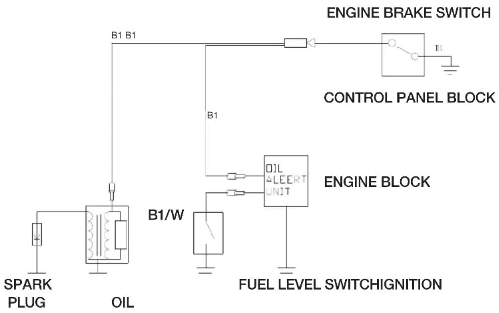
8. WIRING DIAGRAM
WARRANTY CARD
![graph TD A[" "] --> B["Product model"] B --> C["Serial number"] C --> D["Username"] E[" "] --> F["Date of sale"] G[" "] --> H["Company"] I[" "] --> J["Client's signature"]](/content/2026/07/1451272/images/4818caf3e756800baf7b525262ee526607630bfd4502b707d7aa5eb197cad497.jpg)
The product is in good conditions and fully complete. Read and agree the terms of the warranty.
GUARANTEE
The warranty period starts from the date of sale of the products and covers 1 year for all power products.
During the warranty period, free failures caused due to the use of poor-quality materials in the production and manufacturer workmanship admitted fault are removed. The guarantee comes into force only when warranty card and cutting coupons are properly filled. The product is accepted for repair in its pure form and full completeness.
WARRANTY DOES NOT COVER
- Mechanical damage (cracks, chips, etc.) and damage caused by exposure to aggressive media, foreign objects inside the unit and air vents, as well as for damage occurred as a result of improper storage (corrosion of metal parts);
- Failures caused by overloading or product misuse, use of the product for other purposes. A sure sign of overload products is melting or discoloration of parts due to the high temperature, simultaneous failure of two or more nodes, teaser on the surfaces of the cylinder and the piston or destruction of piston rings. Also, the warranty does not cover failure of the automatic voltage regulator due to incorrect operation;
- Failure caused by clogging of the fuel and cooling systems;
- Wearing parts (carbon brushes, belts, rubber seals, oil
seals, shock absorbers, springs, clutches, spark plugs, mufflers, nozzles, pulleys, guide rollers, cables, recoil starter, chucks, collets, removable batteries, filters and safety elements, grease, removable devices, equipment, knives, drills, etc.);
• Electrical cables with mechanical and thermal damage;
- Product opened or repaired by a non-authorized service center.
- Prevention, care products (cleaning, washing, lubrication, etc.), installation and configuration of the product;
• Natural wear products (production share);
- Failures caused by using the product for the needs related to business activities;
- If the warranty card is empty or missing seal (stamp) of the Seller;
- The absence of the holder's signature on the warranty card.


DAEWOO
POWER PRODUCTS


- INDEX
- SAFETY INFORMATION
- COMPONENT & CONTROL LOCATION
- BEFORE OPERATION CHECKS
- IS YOUR ENGINE READY TO GO
- CHECK THE ENGINE
- ELECTRIC STARTER TYPES
- OPERATION
- SAFE OPERATING PRECAUTIONS
- STARTING THE ENGINE
- RECOIL STARTER
- NOTICE
- ENGINE SWITCH (APPLICABLE TYPES)
- STOPPING THE ENGINE
- MAINTENANCE
- OIL LEVEL CHECK
- OIL FILL HOLE
- OIL CHANGE
- OIL FILLER CAP/DIPSTICK
- RECOMMENDED OIL
- AIR CLEANER
- INSPECTION
- OIL-BATH TYPE
- SEDIMENT CUP CLEANING
- SPARK PLUG
- THROUBLESHOOTING
- WARNING
- SPECIFICATIONS
- MODEL: GAE152F
- MODEL: GAE156F
- MODEL: GAE168FA
- MODEL: GAE168FB
- MODEL: GAE170F
- MODEL: GAE173F
- MODEL: GAE177F
- MODEL: GAE182F
- MODEL: GAE188F
- MODEL: GAE190F
- MODEL: GAE192F
- WIRING DIAGRAM
- WARRANTY CARD
- GUARANTEE
- WARRANTY DOES NOT COVER
- DAEWOO
- POWER PRODUCTS
Brand : DAEWOO
Model : GAE168FB
Category : Generator