
ASP 2 - Audio Accessories SENNHEISER - Free user manual and instructions
Find the device manual for free ASP 2 SENNHEISER in PDF.

| Brand | Sennheiser |
| Model | ASP 2 |
| Product type | Power adapter |
| Category | Audio accessories |
| Dimensions (approx.) | 10 x 5 x 3 cm |
| Weight (approx.) | 200 g |
| Input voltage | 100-240 V AC, 50/60 Hz |
| Output voltage | 12 V DC |
| Output current | 500 mA |
| Output connector | Cylindrical plug 5.5 x 2.1 mm |
| Cable length | 1.5 m |
| Main functions | Power supply for Sennheiser microphones (Evolution series, etc.) |
| LED indicator | Yes, power indicator |
| Protection | Against overvoltages and short circuits |
| Housing material | Flame-retardant ABS |
| Operating temperature | 0°C to 40°C |
| Maintenance and cleaning | Unplug before cleaning; use a soft, dry cloth |
| Safety | Do not expose to moisture; indoor use only |
| Spare parts and repairability | Replaceable power cable; no user-serviceable parts |
| Certifications | CE, RoHS |
| General information | Made in Germany by Sennheiser electronic GmbH & Co. KG |
Frequently Asked Questions - ASP 2 SENNHEISER
User questions about ASP 2 SENNHEISER
0 question about this device. Answer the ones you know or ask your own.
Ask a new question about this device
Download the instructions for your Audio Accessories in PDF format for free! Find your manual ASP 2 - SENNHEISER and take your electronic device back in hand. On this page are published all the documents necessary for the use of your device. ASP 2 by SENNHEISER.
USER MANUAL ASP 2 SENNHEISER
Antenna Splitter 1:4
ASP 2
Instructions for use
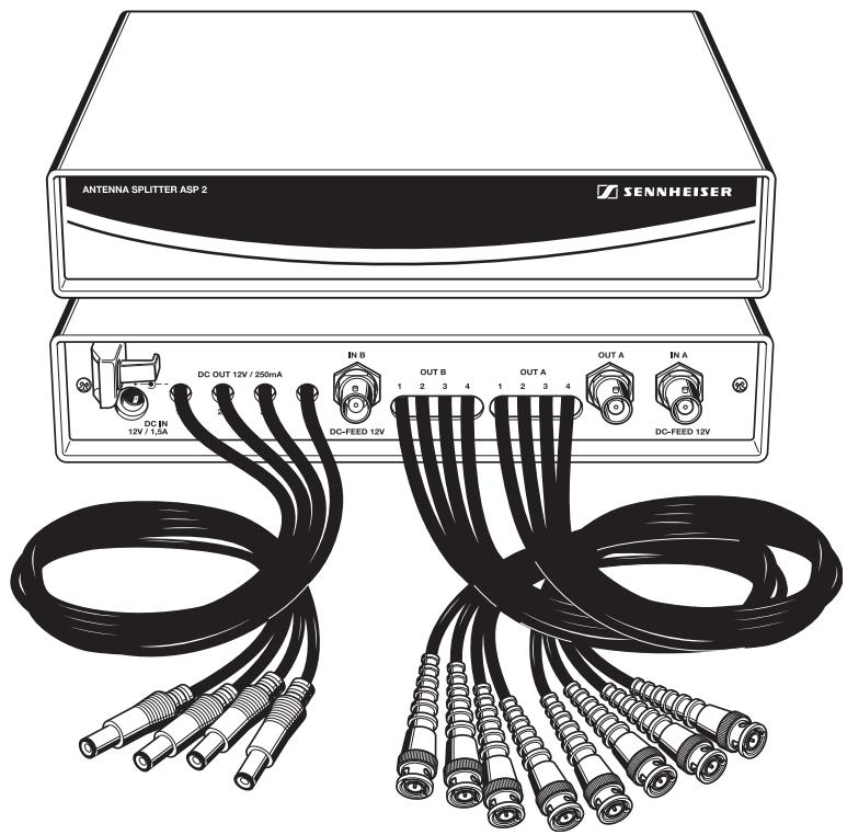
Brief description
The ASP 2 passive RF antenna splitter has been designed for routing antenna signals to several receivers in a multi-channel system, i.e. up to four diversity receivers are supplied with the signals of only two antennas. The antenna splitter incorporates DC distribution for powering up to four receivers in addition to two antenna boosters via a single mains unit. By linking two ASP 2 antenna splitters, an 8-channel system can be operated with only two antennas.
By using the GA 2 rack adapter, two antenna splitters or one antenna splitter and one rack-mount receiver (e.g. EM 100 G2, EM 300 G2 or EM 500 G2) can be mounted into a 19'' rack.
Areas of application:
- Small to medium RF installations (fixed or mobile)
- Permanent installations in small theaters, conference centers and similar venues
Delivery includes
1 ASP 2 antenna splitter
1 set of plastic feet
- Instructions for use
Safety instructions

Caution!
Never open the unit! If units are opened by you in breach of this instruction, the warranty becomes null and void.

Attention!
Make sure that the air vents of the unit are not covered or blocked! Keep the unit away from central heating radiators and electric heaters!

Caution!
Set up the unit on an even surface or mount it into a rack! Lay the cables in such a way that no-one can stumble over them!
Attention!
Keep liquids and small parts which conduct electricity away from the unit! Use a slightly damp cloth for cleaning the unit. Do not use any solvents or cleansing agents!
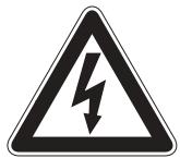
Operating controls
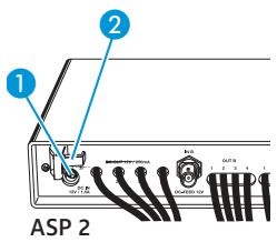
DC input (DC IN) for mains unit
Cable grip for power supply DC cable
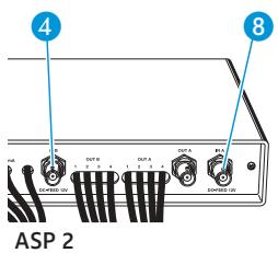
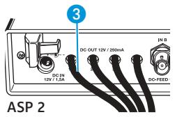
3 Four DC outputs (DC OUT) for powering up to four receivers
4 Antenna input B (IN B, DC-FEED 12 V), BNC socket
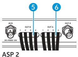
5 Four antenna outputs (OUT B), B leg
6 Four antenna outputs (OUT A), A leg
RF output A (link to antenna input B to make a 1-to-8 splitter), BNC socket
Antenna input A (IN A, DC-FEED 12 V), BNC socket
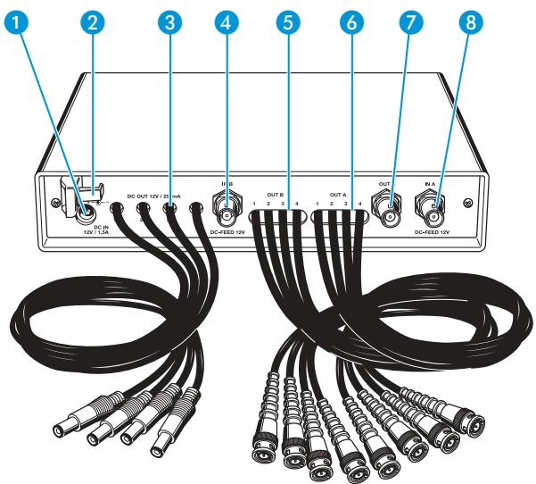
Putting the unit into operation
The below connection diagram shows the connections for a 4-channel diversity system.
Setting up the unit
The unit is suitable for use as table top or can be mounted into a rack.
For mounting the unit into a 19" rack, use the GA 2 rack adapter (optional accessory).
For table top use, fix the plastic feet to the base of the unit.
Note:
Some furniture surfaces have been treated with varnish, polish or synthetics which might cause stains when they come into contact with other synthetics. Despite a thorough testing of the synthetics used by us, we cannot rule out the possibility of staining.
Connecting the antennas
You can connect the following antenna types to the antenna inputs 4 and 8:
- two A 1031-U or A 2003-U passive antennas or
- two A 12 active antennas or
- a combination of passive antenna (A 1031-U or A 2003-U) and antenna booster (AB 2).
Connecting the receivers
You can connect up to four rack-mount receivers (e.g. EM 100 G2, EM 300 G2 or EM 500 G2) to the ASP 2. The splitter incorporates DC distribution for powering the receivers.
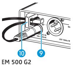
Pass the cables coming from the antenna spitter's DC outputs through the cable grips at the rear of the receivers.
Insert the hollow jack plugs into the sockets of the receivers.
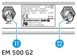
Connect the BNC cables 5 and 6 of the antenna splitter to the receivers as follows:
- Antenna outputs (OUT A) 6 to antenna inputs (ANT I) 12
- Antenna outputs (OUT B) 5 to antenna inputs (ANT II) 11
Note!
We recommend protecting unused RF outputs with a 50 terminator in order to keep to the specified distribution attenuation.
Connecting the mains unit
The NT 1 mains unit can power up to four receivers. The DC power is also available at the antenna inputs for powering two optional antenna boosters.
Pass the cable through the cable grip 2.
Insert the DC connector on the power supply cable into the DC input ①.
Note:
The antenna splitter has no power switch.
Error checklist
| Problem | Possible cause | Possible solution |
| Receivers cannot be switched on | Receivers are not powered | Check the connections of the mains unit or the DC connections |
| Disturbed reception or no reception | Transmitting antennas are not within the range of the receiving antennas | Reduce the distance between transmitter and receiving antennas |
| Transmitters or receivers are not switched on | Switch the transmitters or receivers on | |
| Antennas are not connected correctly | Check the antenna connections | |
| Connecting cables are defective | Replace the connecting cables | |
| Too high cable attenuation due to too long antenna cables or wrong type of antenna cable | Only use the recommended antenna cables (see “Accessories” on page 21) or use shorter antenna cables | |
| Transmitters and receivers are not on the same frequency | See operating manual of the transmitter or receiver |
If problems occur that are not listed above or if the problems cannot be solved with the proposed solutions, please contact your local Sennheiser agent for assistance.
Specifications
Antenna splitter 2 × 1:4 or 1 × 1:8 , passive
Frequency range 500 to 870 MHz
Distribution attenuation approx. 10 dB IN B/OUT B (4 x)
approx. 14 dB IN A/OUT A (4 x)
approx. 6 dB IN A/OUT A
Dimensions approx. 212× 145× 38mm
Weight approx. 700 g
Voltage range 12 V DC nominal, max. 16 V DC
Accessories
NT 1 Mains unit for powering up to four receivers and two antenna boosters, European version
NT 1-120 Mains unit for powering up to four receivers and two antenna boosters, 120V version
NT 1-UK Mains unit for powering up to four receivers and two antenna boosters, UK version
GZL 1019-A1 BNC-BNC coaxial cable, length 1 m
GZL 1019-A5 BNC-BNC coaxial cable, length 5m
GZL 1019-A10 BNC-BNC coaxial cable, length 10m
A 1031-U Passive UHF antenna
AB2 Antenna booster
GA2 19" rack adapter
AM 2 Antenna mount for mounting antennas to the front of the GA 2
A 2003-UHF UHF directional antenna
A 12 Active UHF directional antenna
BNC terminator (50 Ω)
Voltage isolation adapter
Application example
Two ASP 2 antenna splitters can be linked to make a 1-to-8 diversity splitter.
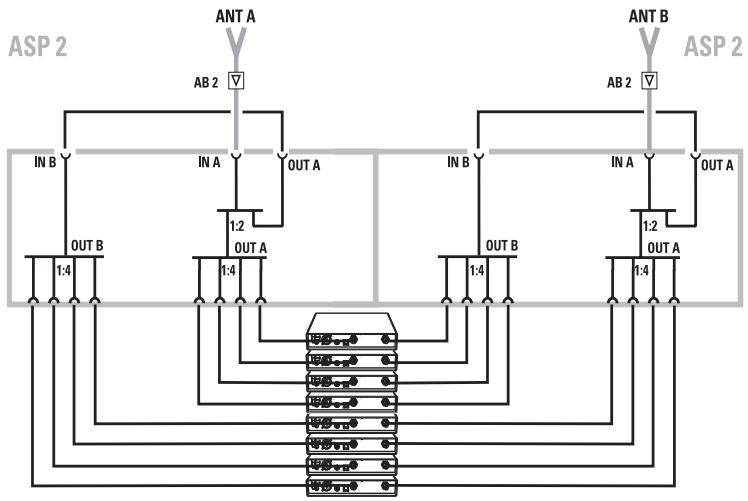
Connections for an 8-channel system
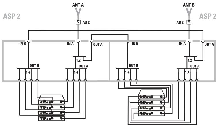
Linking two 4-channel systems
ENGLISH
The guarantee period for this Sennheiser product is 24 months from the date of purchase. Excluded are accessory items, rechargeable or disposable batteries that are delivered with the product; due to their characteristics these products have a shorter service life that is principally dependent on the individual frequency of use.
The guarantee period starts from the date of original purchase. For this reason, we recommend that the sales receipt be retained as proof of purchase. Without this proof (which is checked by the responsible Sennheiser service partner) you will not be reimbursed for any repairs that are carried out.
Depending on our choice, guarantee service comprises, free of charge, the removal of material and manufacturing defects through repair or replacement of either individual parts or the entire device. Inappropriate usage (e.g. operating faults, mechanical damages, incorrect operating voltage), wear and tear, force majeure and defects which were known at the time of purchase are excluded from guarantee claims. The guarantee is void if the product is manipulated by nonauthorised persons or repair stations.
In the case of a claim under the terms of this guarantee, send the device, including accessories and sales receipt, to the responsible service partner. To minimise the risk of trans-port damage, we recommend that the original packaging is used. Your legal rights against the seller, resulting from the contract of sale, are not affected by this guarantee.
The guarantee can be claimed in all countries outside the U.S. provided that no national law limits our terms of guarantee.
Sennheiser electronic GmbH & Co. KG declare that this device is in compliance with the applicable CE standards and regulations.
Certification
30900 Wedemark, Germany
Phone: +49 (5130) 600 0
Fax: +49 (5130) 600 300
www.sennheiser.com
- Antenna Splitter 1:4
- ASP 2
- Brief description
- Delivery includes
- Safety instructions
- Caution!
- Attention!
- Operating controls
- Putting the unit into operation
- Setting up the unit
- Note:
- Connecting the antennas
- Connecting the receivers
- Note!
- Connecting the mains unit
- Specifications
- Accessories
- Application example
- ENGLISH
- Certification
Brand : SENNHEISER
Model : ASP 2
Category : Audio Accessories