
PADKONTROL - MIDI Controller KORG - Free user manual and instructions
Find the device manual for free PADKONTROL KORG in PDF.
| Product Type | Pad MIDI Controller |
| Brand | KORG |
| Model | PADKONTROL |
| Assignable Pads | 16 velocity-sensitive pads |
| X-Y Touchpad | Yes |
| Configurable Buttons | 2 |
| Pedal Jack | Yes (momentary switch) |
| Interfaces | USB, MIDI IN/OUT, pedal |
| Scene Memories | 16 user + 30 presets |
| Power Supply | USB bus-powered or DC9V AC adapter (optional) |
| Current Consumption | Approx 150 mA (max 180 mA) |
| Dimensions (W × D × H) | 314.2 × 233.6 × 55.1 mm |
| Weight | 960 g |
| Supported Operating Systems | Windows XP, Mac OS X 10.2 or later |
| Included Software | USB-MIDI drivers, Editor/Librarian |
| Maintenance | Dry cloth, no solvents |
| Safety | Avoid exposure to sun, moisture, shocks; use appropriate voltage |
| Spare Parts / Options | AC adapter (DC9V), PS-1 pedal switch |
| Repairability | Contact Korg dealer for repair |
Frequently Asked Questions - PADKONTROL KORG
User questions about PADKONTROL KORG
0 question about this device. Answer the ones you know or ask your own.
Ask a new question about this device
Download the instructions for your MIDI Controller in PDF format for free! Find your manual PADKONTROL - KORG and take your electronic device back in hand. On this page are published all the documents necessary for the use of your device. PADKONTROL by KORG.
USER MANUAL PADKONTROL KORG
Main features 5
Top and rear panels 6
Installing the MIDI driver and software 8
Contents of the CD-ROM 8
Windows XP users 8
Mac OS X users 10
Making connections and turning on the power 12
USB connections 12
MIDI connections 12
About the illumination mode 13
Quick start 14
Try out the padKONTROL! 14
Making controller assignments 14
Saving a scene 15
Using your computer to manage scene sets 15
Restoring the factory settings 15
Loading a single preloaded scene 15
Play mode 16
Using the controllers 16
Transmitting a Program Change 16
Transmitting MIDI messages 17
Using a fixed velocity 17
The Flam function 18
The Roll function 18
The Hold function 18
Recalling a scene 18
Saving a scene 18
Shortcuts for assigning messages 19
Setting mode 20
Assigning a Note message to a trigger pad 20
Assigning a Control Change to a trigger pad 21
Assigning the same parameter value to all of the trigger pads 22
Assigning a Note message to the pedal 22
Assigning a Control Change to the pedal 23
X-Y Pad settings 24
Assignable Knob 1/2 settings 25
Flam function settings 26
Roll function settings 26
Fixed Velocity setting 27
Appendix 28
About the padKONTROL and the driver ports 28
About the padKONTROL's MIDI connectors 28
About Korg Native mode 28
Troubleshooting 29
Specifications 29
List of key operations 30
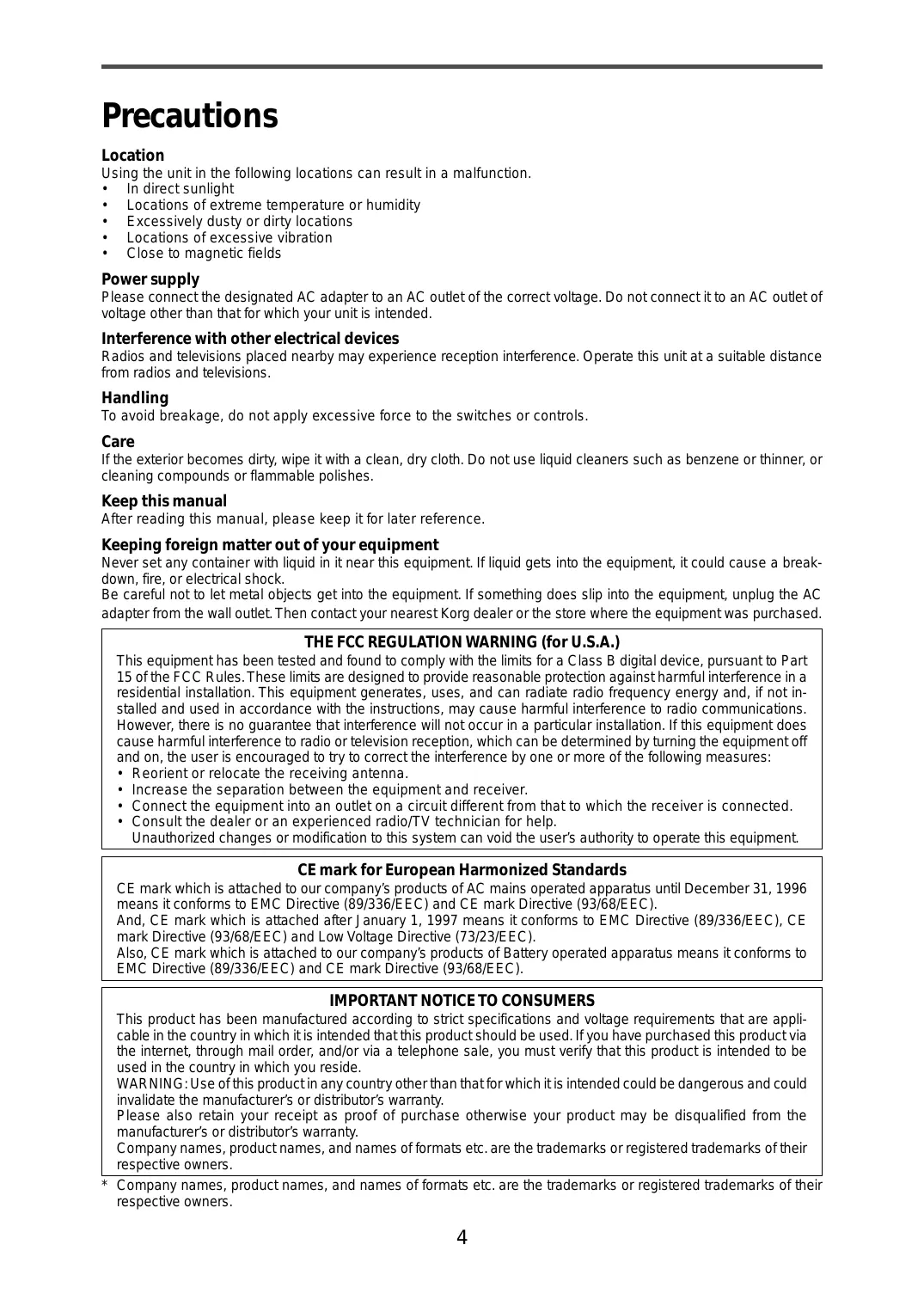
Precautions
Location
Using the unit in the following locations can result in a malfunction.
In direct sunlight
- Locations of extreme temperature or humidity
- Excessively dusty or dirty locations
- Locations of excessive vibration
- Close to magnetic fields
Power supply
Please connect the designated AC adapter to an AC outlet of the correct voltage. Do not connect it to an AC outlet of voltage other than that for which your unit is intended.
Interference with other electrical devices
Radios and televisions placed nearby may experience reception interference. Operate this unit at a suitable distance from radios and televisions.
Handling
To avoid breakage, do not apply excessive force to the switches or controls.
Care
If the exterior becomes dirty, wipe it with a clean, dry cloth. Do not use liquid cleaners such as benzene or thinner, or cleaning compounds or flammable polishes.
Keep this manual
After reading this manual, please keep it for later reference.
Keeping foreign matter out of your equipment
Never set any container with liquid in it near this equipment. If liquid gets into the equipment, it could cause a breakdown, fire, or electrical shock.
Be careful not to let metal objects get into the equipment. If something does slip into the equipment, unplug the AC adapter from the wall outlet. Then contact your nearest Korg dealer or the store where the equipment was purchased.
THE FCC REGULATION WARNING (for U.S.A.)
This equipment has been tested and found to comply with the limits for a Class B digital device, pursuant to Part 15 of the FCC Rules. These limits are designed to provide reasonable protection against harmful interference in a residential installation. This equipment generates, uses, and can radiate radio frequency energy and, if not installed and used in accordance with the instructions, may cause harmful interference to radio communications.
However, there is no guarantee that interference will not occur in a particular installation. If this equipment does cause harmful interference to radio or television reception, which can be determined by turning the equipment off and on, the user is encouraged to try to correct the interference by one or more of the following measures:
- Reorient or relocate the receiving antenna.
- Increase the separation between the equipment and receiver.
- Connect the equipment into an outlet on a circuit different from that to which the receiver is connected.
- Consult the dealer or an experienced radio/TV technician for help.
Unauthorized changes or modification to this system can void the user's authority to operate this equipment.
CE mark for European Harmonized Standards
CE mark which is attached to our company's products of AC mains operated apparatus until December 31, 1996 means it conforms to EMC Directive (89/336/EEC) and CE mark Directive (93/68/EEC).
And, CE mark which is attached after January 1, 1997 means it conforms to EMC Directive (89/336/EEC), CE mark Directive (93/68/EEC) and Low Voltage Directive (73/23/EEC).
Also, CE mark which is attached to our company's products of Battery operated apparatus means it conforms to EMC Directive (89/336/EEC) and CE mark Directive (93/68/EEC).
IMPORTANT NOTICE TO CONSUMERS
This product has been manufactured according to strict specifications and voltage requirements that are applicable in the country in which it is intended that this product should be used. If you have purchased this product via the internet, through mail order, and/or via a telephone sale, you must verify that this product is intended to be used in the country in which you reside.
WARNING: Use of this product in any country other than that for which it is intended could be dangerous and could invalidate the manufacturer's or distributor's warranty.
Please also retain your receipt as proof of purchase otherwise your product may be disqualified from the manufacturer's or distributor's warranty.
Company names, product names, and names of formats etc. are the trademarks or registered trademarks of their respective owners.
- Company names, product names, and names of formats etc. are the trademarks or registered trademarks of their respective owners.
Introduction
Thank you for purchasing the padKONTROL MIDI studio controller. To take advantage of everything the padKONTROL has to offer, and to enjoy your padKONTROL to the fullest, please read this manual carefully and use your new padKONTROL only as directed. Please keep this manual for future reference.
Main features
The padKONTROL is a versatile and convenient pad-based MIDI controller that is ideally suited for creating rhythm tracks. It provides sixteen illuminated, velocity sensitive and great-feeling trigger pads, as well as an X-Y pad, an assignable pedal jack, and two assignable knobs for dynamic realtime control. With this flexible array of control elements, the padKONTROL is an excellent choice for freely controlling not only software synthesizers but also external MIDI sound modules or any other music device.
16 trigger pads
When note messages are assigned to these trigger pads, they can transmit either a "fixed" velocity, or the velocity message can vary in proportion to how each pad is struck, allowing drum patterns to be played in realtime using expressive dynamics. Alternatively, control change messages may be assigned to the pads for use as transport controls - or any other type of control switch.
Pedal jack
A foot pedal connected to the padKONTROL can be assigned to send either a note message or a control change message - just like the trigger pads. By assigning a note that plays a bass drum sound, drum patterns can be played in a natural-feeling way, just as if a real kick drum was being used.
X-Y pad
A variety of control change messages may be assigned to this pad, for example Pitch Bend to the X-axis and Reverb Depth to the Y-axis. The unique Roll and Flam functions can instantly adjust the speed and velocity of a roll, or the flam velocity and spacing. This provides even more potential for highly natural and dynamic control.
Two assignable knobs
A variety of control change messages (Pan, Delay Time, etc.) can be assigned to these knobs.
Sixteen user memories
Once assignments have been made for the trigger pads and other controllers, these settings can be saved in one of the padKONTROL's sixteen internal user memories as a "scene." The trigger pads can be used to instantly switch between the sixteen saved scenes. The padKONTROL provides preloaded scenes that are set up ideally for popular drum sound software programs and modules.
USB-MIDI interface functionality
The padKONTROL can function as a USB-MIDI interface. An external MIDI sound module that does not have a USB connector can be connected to your computer via the padKONTROL's USB connector to send and receive MIDI data directly.
Bus power is supported
The padKONTROL's USB connector allows it to be powered directly from a compatible USB bus. When the padKONTROL is connected to a computer via USB, there's no need to supply power via the AC adapter.
■ Editor/Librarian softwae is included
The included Editor/Librarian software lets you use your computer to edit and manage scene data. This software is seamlessly linked with the padKONTROL, making it easy for you to create your own original scenes, and to set up the padKONTROL ideally for your needs.
Top and rear panels
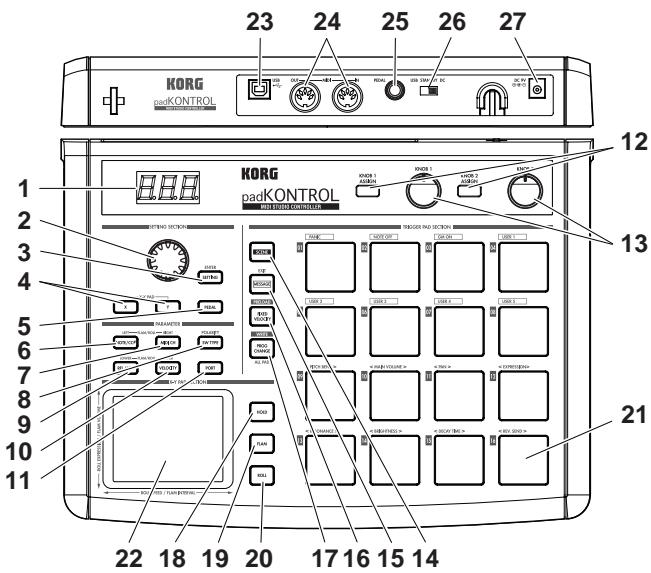
1. Display
The display shows information such as scene numbers and parameter values.
2.Encoder
In Play mode, holding down the [PROG. CHANGE/WRITE/ALL PAD] key and turning the encoder transmits program changes. In Setting mode, it can be used to set parameter values or select MIDI messages.
3.[SETTING/ENTER]key
In Play mode, pressing this key will switch to Setting mode. In Setting mode, pressing this key will finalize the settings and switch back to Play mode. This key is also used when recalling a preloaded scene or to confirm a Scene Store operation.
4. [X]/[Y] keys
These keys are used to assign a parameter to the X-axis or Y-axis of the X-Y pad.
5. [PEDAL] key
This key is used when you want to make settings for a connected pedal.
6.[NOTE/CC#/LEFT]key
This key is used to assign the MIDI messages that will be transmitted by the trigger pads, pedal, assignable knobs, and X-Y pad controllers. When making settings for the Flam/Roll function, this key specifies the value for the left edge of the X-Y pad's X-axis.
7. [MIDI CH/RIGHT] key
This key is used to specify the MIDI channel that the selected trigger pad or foot pedal will transmit messages on. When making settings for the Flam/Roll function, this key specifies the value for the right edge of the X-Y pad's X-axis.
8. [SW TYPE/POLARITY] key
This key is used to select either "momentary" or "toggle" type of behavior for the trigger pads and foot pedal. This key is also used to invert the operation of the assignable knobs and the X-Y pad.
9. [REL. VAL./LOWER] key
This key is used to set the control change value that will be sent when you remove your finger from the X-Y pad, or when a trigger pad or foot pedal is released. When adjusting the Flam/Roll function, this key specifies the value for the lower edge of the X-Y pad's Y-axis.
10. [VELOCITY/UPPER] key
When a note number is assigned to a trigger pad or the pedal, this key is used to select the velocity curve (only for a trigger pad) or to set a fixed velocity value. If a control change is assigned to a trigger pad or the pedal, this parameter specifies the value of the control change message that is transmitted when you press the pad or pedal. When making settings for the Flam/Roll function, this key specifies the value for the upper edge of the X-Y pad's Y-axis.
11.[PORT]key
This key is used to specify the USB-MIDI transmission port that is used by the trigger pads or pedal when the padKONTROL is connected via USB. (p.28 "About the padKONTROL and the driver ports")
12. [KNOB 1 ASSIGN]/[KNOB 2 ASSIGN] keys
These keys are used to assign a specific MIDI message to the assignable knobs.
13. Knob 1, Knob 2
Turning these knobs transmits the MIDI message currently assigned to each knob.
14. [SCENE] key
This key is used for various scene functions such as saving, recalling, and restoring the preloaded scenes.
15.[MESSAGE/EXIT]key
In Play mode, press this key is used to transmit the MIDI messages assigned to trigger pads [1]–[8]; Panic, Note Off, GM on and USER 1–5. You can also press this key to cancel a setting.
16. [FIXED VELOCITY/PRELOAD] key
This key (when lit) applies a single fixed velocity to all the trigger pads and the pedal, ignoring the dynamics and/or preset velocity levels. In Setting Mode, this key is used to set the fixed velocity value.
This key is also used when restoring the preloaded scenes into the padKONTROL.
17. [PROG.CHANGE/WRITE/ALL PAD] key
In Play mode, hold down this key and turn the encoder to transmit program change messages. You can also press this key to store a scene.
In Setting mode, press this key to assign the same setting to all sixteen trigger pads in one operation - such as placing all trigger pads on the same MIDI channel.
18. [HOLD] key
When you press this key in Play mode, the point (value) at which you released your finger from the X-Y pad will be held.
19. [FLAM] key
In Play mode, turning this key on (lit) will enable the Flam function. In Setting mode, pressing this key will allow you to adjust the settings for the Flam function.
20. [ROLL] key
In Play mode, turning this key on (lit) will enable the Roll function. In Setting mode, pressing this key will allow you to adjust the settings for the Roll function.
21. Trigger pads
Each time one of the trigger pads is struck, the note data or control change assigned to that pad will be transmitted. If you've assigned note data, the velocity is also transmitted. These trigger pads are also used to transmit messages, select scenes, or to access shortcuts.
22. X-Y pad
By touching your finger to the X-Y pad, you can transmit the two assigned MIDI messages by touching this pad with your finger. The messages being sent will depend on the MIDI channel and USB-MIDI transmit port specified for the trigger pad or pedal.
When the flam or roll feature is on, the X-Y pad controls the flam or roll parameters.
23. USB connector
Use a USB cable to connect the padKONTROL to your computer so that MIDI messages can be transmitted and received.
24. MIDI connectors
You can connect external MIDI devices to these connectors. The function of the MIDI connectors will differ depending on whether the USB connector is connected to your computer. (p.28 "About the padKONTROL's MIDI connectors")
25. Pedal jack
A momentary pedal such as the Korg PS-1 pedal switch (each sold separately) can be connected to the pedal jack. By pressing the connected pedal you can transmit a note number (C-1-G9) or a control change. The padKONTROL will automatically determine the polarity of the pedal when the power is turned on.
26. Power switch
This switch turns the padKONTROL on by selecting either DC (Adapter) or USB power. When not in use, this switch places the padKONTROL in the standby mode. (p.12 "Making connections and turning on the power")
27. Power supply connector
Connect the optional AC adapter here. In most cases, when the padKONTROL is connected to your computer via USB, the computer will supply the power (bus power), so you won't need the AC adapter.
Installing the MIDI driver and software
Contents of the CD-ROM
The included CD-ROM contains the following.
padKONTROL application installer
Editor/Librarian software
KORG USB-MIDI Driver
Editor/Librarian owner's manual (PDF)
Software license agreement (PDF)
Please read before use
Copyright to all software pertaining to this product is the property of Korg Corporation.
- A license agreement for the software pertaining to this product is included separately. You must read this license agreement before you install the software. Your installation of the software will be taken to indicate your acceptance of the agreement.
Windows XP users
Operating requirements
Computer
A computer with a USB port, that satisfies the operating requirements of Microsoft Windows XP (USB chipset made by Intel Corporation is recommended)
Supported operating systems
Microsoft Windows XP Home Edition/Professional Service pack 1 or later
padKONTROL application installer
The padKONTROL application installer automatically installs the KORG USB-MIDI Driver and Editor/Librarian software from the included CD-ROM.
1 Insert the included CD-ROM into the CD-ROM drive of your computer.
Normally, "padKONTROL Application Installer" will start up automatically.

If because of the settings on your computer, the installer does not start up automatically, double-click "KorgSetup.exe" in the CD-ROM.
2 From the list, select the applications that you want to install and click [Install].
The selected applications will be installed successively. Follow the instructions that appear in the screen to install each of the applications you selected.
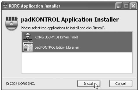
3 When all applications have been installed, click [Finish] to exit the installer.
■ KORG USB-MIDI Driver for Windows XP installation and settings
In order to install or uninstall drivers in Windows XP, you must have Administrator privileges. For details, please contact your system administrator.
2 Set your computer so that driver installation is not prevented by the lack of a digital signature. (p.9 "Allowing driver installation without a digital signature")
This driver is only for Windows XP. It cannot be used in Windows 95/98/Me.
The driver must be installed for each USB port. If you connect the padKONTROL to a USB port other than the USB port you used when installing KORG USB-MIDI Driver for Windows XP, you will need to use the same procehae to reinstall KORG USB-MIDI Driver for Windows XP.
Installing KORG USB-MIDI Driver for Windows XP
Before you install KORG USB-MIDI Driver for Windows XP, you must first use the padKONTROL Application Installer to install KORG USB-MIDI Driver Tools as directed.
1 Use a USB cable to connect the padKONTROL to your computer, and power-on the padKONTROL.
Windows will detect that the padKONTROL is connected.
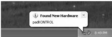
Then the standard driver will be installed automatically.
2 From the taskbar, choose [Start] [All Programs] [KORG] [KORG USB-MIDI Driver Tools] [Install KORG USB-MIDI Device] to start the setup utility.
The list in the upper part of the dialog box will show the KORG USB-MIDI device that are currently connected to the PC. The lower part of the dialog box will show the version information for the KORG USB-MIDI Driver you are about to install.
In the list, select the KORG USB-MIDI device that is currently connected to the PC, and click [Install]. Installation of the device will begin.

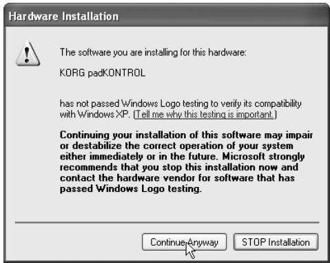
3 During the installation, you may see a dialog box warning you about digital signatures. Please click [Continue] to proceed.
4 When driver installation is completed, click [Finish] to complete the installation. If you are asked to restart Windows, choose [Yes] to restart.
■ Allowing driver installation without a digital signature
If your computer is set so that drivers that are not digitally signed cannot be installed, you will not be able to install the KORG USB-MIDI driver. Proceed as follows to change the setting so that you will be able to install the driver.
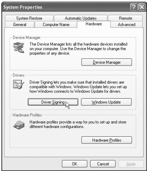
1 From the task bar, click [Start] [Control Panel] to open the Control Panel.
In the Control Panel, start up [System], and click the [Hardware] tab.
Click [Driver Signing].
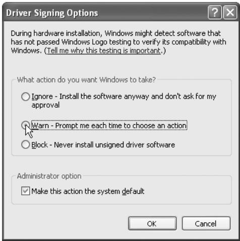
2 If "What action do you want Windows to take?" is set to "Block," you won't be able to install the driver. Choose [Ignore] or [Warn], and click [OK].
If necessary, restore this setting to its original state when you've finished installing the driver.
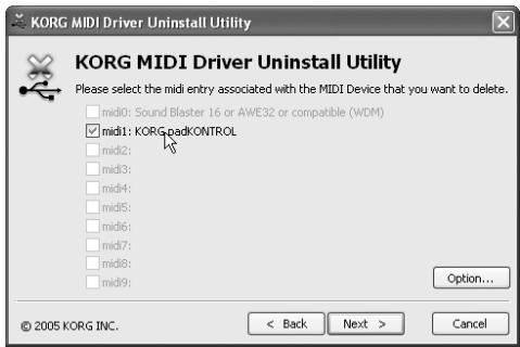
■ Uninstalling KORG USB-MIDI Driver for Windows XP
1 From the task bar, choose [Start] [All Programs] [KORG] [USB MIDI Uninstall] to start up the setup utility. Click [Next >].
2 A list of the currently-installed KORG MIDI devices will appear. Add a check mark only to the MIDI devices that you want to remove.
Please note that all MIDI devices with a check mark will be removed.
Click [Next >].
3 A dialog box will ask you for confirmation. Click [Yes].
4 Click [Finish] to complete the procedure. Restart Windows so that your changes will take effect.
Mac OS X users
Operating requirements
Computer
Apple Macintosh computer with a USB port that satisfies the operating requirements of Mac OS X
Supported operating systems
Mac OS X ver.10.2 or later
Proceed as follows to make your computer recognize the padKONTROL.
1 Use a USB cable to connect the padKONTROL to your computer.
2 Turn on the power of the padKONTROL.
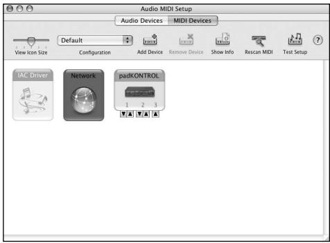
3 Navigate to Macintosh HD > Application folder > Utility folder, and double-click "Audio MIDI Settings".
4 Click the "MIDI Devices" tab, and verify that the padKONTROL is displayed.
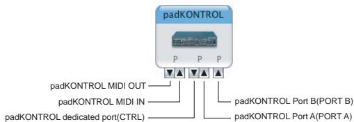
Mac OS X MIDI input and output ports
Using the Mac OS X MIDI drivers, the padKONTROL provides a total of three MIDI inputs and two MIDI outputs, as follows:
- One port each of MIDI input and output for external devices
- Two ports of MIDI input from the padKONTROL's own trigger pads and controllers
One port of MIDI output dedicated to padKONTROL data dumps and Korg Native mode
Input Settings for Applications
If you're using the padKONTROL to control a DAW or similar application, set the input port of your application to Port 2 so that it will receive the MIDI controller messages you've assigned to Port A on the padKONTROL.
| padKONTROL | Names Displayed by Application | |
| Input | (MIDI IN) MIDI IN | (MIDI input settings:) Port 1 |
| (Port A) PORT A | (MIDI input settings:) Port 2 | |
| (Port B) PORT B | (MIDI input settings:) Port 3 | |
| Output | (MIDI OUT Port) MIDI OUT | (MIDI output settings:) Port 1 |
| (Dedicated Port) CTRL | (MIDI output settings:) Port 2 |
■ Installing the Editor/Librarian software
To install the Editor/Librarian in Mac OS X, proceed as follows.
1 Insert the included CD-ROM into your CD-ROM drive.
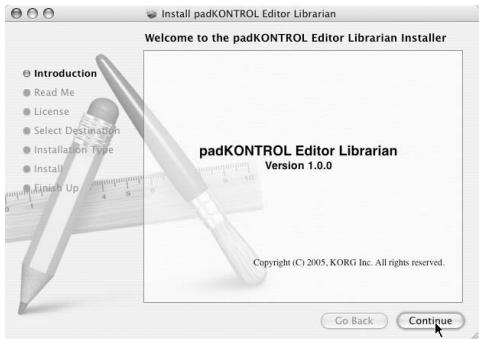
2 In the CD-ROM, navigate to the "padKONTROL" folder which contains the Editor/Librarian software, and double-click "padKONTROL Editor.png" to start up the installer.
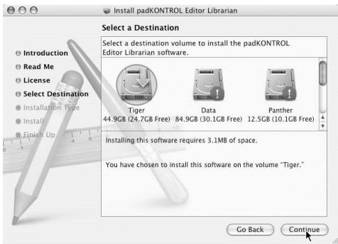
3 When the installer starts up, the following screen will appear. Click [Continue].
4 "Important information" will appear. Read the contents, and click [Continue].
5 "License agreement" will appear. Read the contents, and click [Continue].
A dialog box asking your consent to the software license agreement will appear. If you consent, click [I agree].
6 The "Choose installation location" screen will appear. Choose the desired installation location, and click [Continue].
7 The "Easy Install" dialog box will appear. Click [Install].
8 When installation has been completed successfully, click [Close] to exit the installer.
Making connections and turning on the power
2 Be sure all your equipment is turned off BEFORE you begin hooking everything up. You must exercise caution, otherwise you may damage your speaker system or cause other malfunctions.
USB connections
1 Use a USB cable to connect the padKONTROL to the USB connector of your computer. You may make the USB connection with your computer powered-on. If you want to use a pedal, connect it to the PEDAL jack.
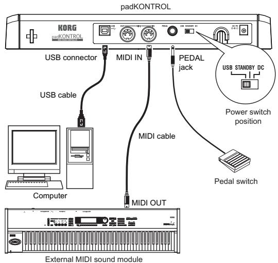
Note The padKONTROL can function as a USB-MIDI interface. You can connect a MIDI sound module or other device to the MIDI OUT connector, and control the MIDI sound module from your computer.
When the padKONTROL is powered-on, it will automatically detect the polarity of the pedal. If a pedal is connected, do not hold it down while you power-on the padKONTROL.
2 To turn on the power, set the padKONTROL's power switch to the USB position.
If you're using a USB connection, power will be supplied from the computer to which the padKONTROL is connected. (This is called "bus power.") The same applies if you're using a self-powered USB hub.
If you're using a USB connection, you don't need to use an AC adapter. However if your computer is low-powered, or if you are using a hub that is only bus-powered (rather than self-powered), power may not be supplied to the padKONTROL. In this case, use the optional AC adapter and set the power switch to the DC position.
3 When you want to turn off the power, set the power switch to the STANDBY position.
Never turn off the power while settings are being saved (written). Doing so may damage the internal data.
If you're using a USB connection, the data from the computer is transmitted from the padKONTROL's MIDI OUT connector. MIDI messages generated by operating the padKONTROL's trigger pads and X-Y pad will not be transmitted from the MIDI OUT connector. (p.28)
MIDI connections
1 Connect the plug of the optional AC adapter to the padKONTROL's power connector, and plug the adapter into an AC outlet.
2 Use a MIDI cable to connect the padKONTROL to your external MIDI sound module. If you want to use an optional pedal, connect it to the pedal jack.
The padKONTROL detects the polarity of the pedal when the power is turned on. If a pedal is connected, do not hold it down while you power-on the padKONTROL.
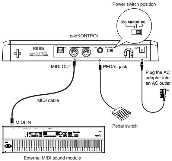
3 When you set the padKONTROL's power switch to the DC position, the power will turn on.
4 Power-on your connected external MIDI sound module.
5 When you are ready to turn off the power, power-off the connected external MIDI sound module first, and then set the padKONTROL's power switch to STANDBY.
Never turn off the power while settings are being saved (written). Doing so may damage the internal data.
About the illumination mode
This mode causes the trigger pad LEDs to blink in a unique pattern. This produces a particularly striking effect when used during a live performance on a dimly lit stage; it looks cool sitting in the studio, too.
To select a pattern:
-
Pattern A Power-on while holding down the [SETTING/ENTER] and [MESSAGE/EXIT] keys.
Pattern A produces an "expanding box" type of pattern each time a trigger pad is struck. -
Pattern B Power-on while holding down the [SETTING/ENTER] and [FIXED VELOCITY/PRELOAD] keys.
-
Pattern B produces a "domino effect" type of pattern each time a trigger pad is struck.
-
Pattern C Power-on while holding the [SETTING/ENTER] and [PROG CHANGE/WRITE/ALL PAD] keys. If the padKONTROL has not been touched for few minutes, the trigger pads will start to blink in a variety of generated patterns. Once you touch the padKONTROL, they will stop.
Mode Off Power-on while holding down the [SETTING/ENTER] key and [SCENE] key.

The illumination mode setting is retained even when the power is off, providing you power-on in the usual way. You do not need to reset this parameter each time you turn on the padKONTROL.
Quick start
Try out the padKONTROL!
Turn the power on
Connect the padKONTROL to your computer and turn the power on. (p.12 "Making connections and turning on the power")
When the power turns on, the padKONTROL will be in Play mode, and scene 1 will be loaded. The display will indicate "
In Play mode, the [SETTING/ENTER] key is dark.
Recalling a scene
The padKONTROL lets you assign the parameters you want to the trigger pads, the X-Y pads, and the two assignable knobs so that you can control your external MIDI sound module or a software synthesizer on your computer in whatever way is most appropriate for your needs. A set of these assignments is called a "scene." The padKONTROL's internal user memory contains sixteen scenes, and you can instantly recall any of these scenes using the sixteen trigger pads.
As an example, here's how to recall scene number 5.
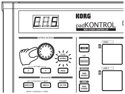
1 Hold down the [SCENE] key.
The [SCENE] key and the trigger pad corresponding to the currently selected scene number will light.
![KORG PADKONTROL - Hold down the [SCENE] key. - 1](/content/2019/11/143957/images/4d4828c0a8a81d250b3da12a6ff1ac340b8fbbf0d67d4bb57ef0020a28804c0d.jpg)
2 Continuing to hold down the [SCENE] key, press trigger pad [05], which has an indication of "05" printed at the upper left of the trigger pad.
The scene will change, and trigger pad [05] will light.
The display will indicate "505".
![KORG PADKONTROL - Hold down the [SCENE] key. - 2](/content/2019/11/143957/images/645086a359142324319f55e5495acc9f62add3d79594a767b7a39810aa54e894.jpg)
As long as you continue holding down the [SCENE] key, you'll be able to use the trigger pads to switch scenes.
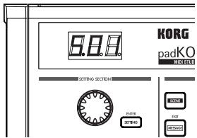
3 Release the [SCENE] key to return to Play mode.
![KORG PADKONTROL - Hold down the [SCENE] key. - 3](/content/2019/11/143957/images/5e1d75b95e32b14036c71ae48dd9a489e0c2ad1dbddaf6392fb54ae919a2a1db.jpg)
Scenes can also be recalled in Setting mode.
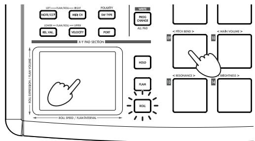
Using the Roll function and Flame functions
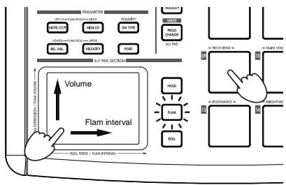
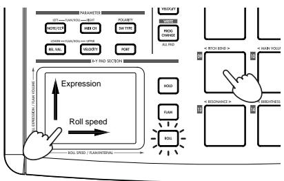
The Roll function makes it easy to simulate a roll (rapidly repeated strikes on the same drum). The Flam function simulates a flam (double-strike on the same drum). By moving your finger on the X-Y pad you can realistically and dynamically control the roll or flam in realtime. The X-axis controls the speed of the roll (or the flam interval), and the Y-axis controls the roll expression (or the volume of the second strike of the flam). The example below describes using the roll function, but you can try out the flam function in the same way.
1 Press the [ROLL] key.
The Roll function will turn on, and the [ROLL] key will light.
2 Place your finger on the X-Y pad, and press a trigger pad to which a snare drum or similar sound is assigned. A roll will play as long as you continue holding down the trigger pad. The roll will stop when you release the pad.
Making controller assignments
If you want a controller (e.g., trigger pad or pedal) to control a different parameter, you can change the assignment and setting for that controller.
- As an example, let's assign trigger pad [3] so that it transmits a MIDI Note-on message for note number C5 when pressed.
1 Press the [SETTING/ENTER].
You will enter Setting mode, and the [SETTING/ENTER] key will light.
2 Press trigger pad [3].
Trigger pad [3] will be selected and will light.
3 Press the [NOTE/CC#/LEFT] key.
Now you can specify a note message or control change. The [NOTE/CC#/LEFT] key will light. In the display, the note number or control change number will blink.
4 While you watch the display, use the encoder to select 5 .
5 Press the [SETTING/ENTER] key.
This completes the assignment. You will return to Play mode. The [SETTING/ENTER] key will go dark, and the display will indicate the scene number.

If you decide to cancel before you've completed the procedure, press the [MESSAGE/EXIT] key.
Saving a scene
If you switch to another scene or turn off the power before saving the controller assignment you've made, your changes will be lost. If you want to keep the changes you have made, you must save them.
You can save scenes either in Play mode or in Setting mode.
As an example, we can save your edited scene data as scene number 2.
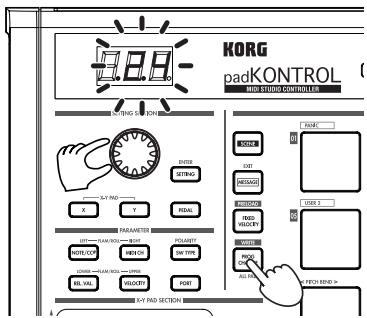
1 Hold down the [PROG. CHANGE/WRITE/ALL PAD] key and press the [SCENE] key.
2 The save-destination scene number will blink in the display. Use the encoder to select "SΩZ" (scene 2).

The trigger pad corresponding to the scene number will also blink. At this time, you can also make your selection by directly pressing the trigger pad that corresponds to the desired scene number.
3 Press the [SETTING/ENTER] key.
The assignments have now been stored to scene 2.

Never turn off the power while settings are being saved. Doing so may damage the internal data.

If you decide to cancel before you've completed the procedure, press the [MESSAGE/EXIT] key.

You can also save (write) a scene when you're in Setting mode.
Using your computer to manage scene sets
You can use the included Editor/Librarian software to save, edit, and manage the sixteen scenes saved in the padKONTROL as a single "scene set" on your computer.
For details on how to use the Editor/Librarian software, refer to the "Editor/Librarian owner's manual" on the included CD-ROM.
Restoring the factory settings
The padKONTROL contains 30 preloaded scenes (P.01-P.30).
When the padKONTROL leaves the factory, sixteen of these thirty-two scenes are already loaded into the user memory (S.01-S.16). You can restore the preloaded factory settings at any time.

You can restore the factory settings whether you're in Play mode or in Setting mode.
1 Hold down the [SCENE] key and press the [FIXED VELOCITY/PRELOAD] key.
The [FIXED VELOCITY/PRELOAD] key will light, and the [SETTING/ENTER] key will blink. The display will indicate the preloaded scene number.

Use the encoder to select "RLL".

Press the [SETTING/ENTER] key. The display will blink "L od" and loading will begin. After a time, the blinking will stop. Loading has been completed.

If you decide to cancel before you've completed the procedure, press the [MESSAGE/EXIT] key. However, you can't cancel while loading is actually occurring.
Loading a single preloaded scene
Refer to the Preloaded Scene List (p.114) and choose the scene you want to load. You can load any of the 30 preloaded scenes into one of the user scene memories (S.01-S.16).

You can load a preloaded scene whether you're in Play mode or in Setting mode.
1 Hold down the [SCENE] key and press the [FIXED VELOCITY/PRELOAD] key.
The [FIXED VELOCITY/PRELOAD] key will light and the [SETTING/ENTER] key will blink. The display will indicate the preloaded scene number.

Use the encoder to select the preloaded scene you want to load.
Preload Scene Number: P.01-P.30

Press the [SETTING/ENTER] key.

Next, select the user memory location that the preloaded scene will be loaded into.
Scene No.: S.01-S.16

Press the [SETTING/ENTER] key.
The padKONTROL will be in Setting mode with the newly loaded scene selected.

Never turn off the power while data is being saved. Doing so may damage the internal data.

If you decide to cancel before you've completed the procedure, press the [MESSAGE/EXIT] key.
Play mode
In Play mode you can use the padKONTROL's controllers and functions to control a connected external MIDI device or a software synthesizer or DAW running on your computer. When you power-on the padKONTROL, it will always enter Play mode with scene 1 selected. The display will indicate "50 I". In Play mode the [SETTING/ENTER] key will be dark. If you want to change from Setting mode to Play mode, press the [SETTING/ENTER] key to make it go dark.
Using the controllers
In Play mode you can use four types of controllers.
Trigger pads
Each time you press a trigger pad, the assigned note data or control change will be transmitted.
Trigger pads to which a control change is assigned will remain lit in Play mode so that they can be easily identified.
When you press a trigger pad to which a note message is assigned, the note message will be transmitted at the assigned velocity value. (p.20)
When you press a trigger pad to which a control change is assigned, the control change will be transmitted with the assigned On value when pressed, and transmitted again with the assigned Release value when released. (p.21)
Display indication
When you press a trigger pad to which a note message is assigned, the display will indicate the velocity value. After a time, the display will revert to the scene number. When you press a trigger pad to which a control change is assigned, the display will indicate the control change value. After a time, the display will revert to the scene number.
Pedal
Each time you operate a pedal connected to the Pedal jack, the assigned note data or control change will be transmitted.
If a note message is assigned, the note message will be transmitted with the assigned velocity value. (p.23)
If a control change is assigned, the message will be transmitted with the specified On value and Release value. (p.24)
Display indication
If a note message is assigned to the pedal, the display will indicate the velocity value. After a time, the display will revert to the scene number.
If a control change is assigned, the display will indicate the control change value. After a time, the display will revert to the scene number.
X-Y pad
When you operate the X-Y pad, the assigned MIDI messages will be transmitted. (p.24)
The upper edge and right edge of the X-Y pad produce higher values, and the lower edge and left edge produce lower values. You can reverse these directions if desired. When you take your finger off of the X-Y pad, it will return to the specified point (Release Point). (p.25)
■ Assignable Knobs 1/2
When you turn assignable knobs 1/2, the assigned MIDI messages will be transmitted. (p.25)
Transmitting a Program Change
Here's how you can transmit a program change message in Play mode.
1 Hold down the [PROG CHANGE/WRITE/ALL PAD] key and turn the encoder.
The program number will blink in the display.
<Example Program number 24
2 When you release the [PROG CHANGE/WRITE/ALL PAD] key, a program change message will be transmitted with the program number that was shown in the display. Then the display will return to indicating the scene number.
This program change message is transmitted on the MIDI channel of each trigger pad and pedal whose MIDI Transmit Channel is set to other than Disable.
Transmitting MIDI messages
Various useful types of MIDI message are preassigned to trigger pads [1]–[3]. In addition, you can use the included Editor/Librarian software to create User Messages and assign them to trigger pads [4]–[8]. In Play mode, hold down the [MESSAGE/EXIT] key and press a trigger pad [1]–[8] to transmit the assigned MIDI message.
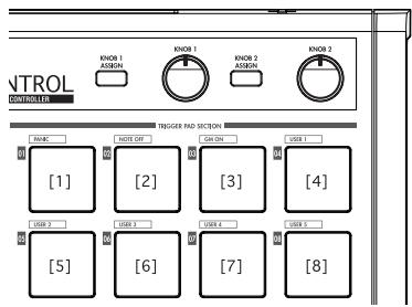
[1] PANIC
This transmits All Note Off [Bn, 7B, 00], All Sound Off [Bn, 78, 00], and Reset All Controllers [Bn, 79, 00] messages on all MIDI channels.
Execute this if the connected software becomes unstable, or if you experience "stuck notes" on your MIDI sound module.
1 Hold down the [MESSAGE/EXIT] key and press trigger pad [1].
All Note Off, All Sound Off, and Reset All Controllers messages will be transmitted on all MIDI channels. The display will show a graphic indication of the transmission.
This message is transmitted to both port A and port B, regardless of the port you specified (p.21-26 "USB-MIDI Port").
[2] NOTE OFF
This transmits an All Note Off [Bn, 7B, 00] message on all MIDI channels.
1 Hold down the [MESSAGE/EXIT] key and press trigger pad [2].
All Note Off messages will be transmitted on all MIDI channels. The display will show a graphic indication of the transmission.
This message is transmitted to both port A and port B, regardless of the port you specified (p.21-26 "USB-MIDI Port").
[3] GMON
This transmits a GM System On [F0, 7E, 7F, 09, 01, F7] message.
1 Hold down the [MESSAGE/EXIT] key and press trigger pad [3].
A GM System On message will be transmitted. The display will show a graphic indication of the transmission.
This message is transmitted to the port you specify (p.21-26 "USB-MIDI Port").
[4]-[8] USER1-5
This will transmit the MIDI message you created using the included Editor/Librarian software.
1 Hold down the [MESSAGE/EXIT] key and press trigger pad [4]-[8].
The MIDI message you assigned will be transmitted. The display will show a graphic indication of the transmission. User message numbers 1-5 correspond to trigger pads [4]-[8].
These messages will be transmitted to the port you specify in the Editor/Librarian software. For details, refer to the owner's manual for the Editor/Librarian software.
Using a fixed velocity
By turning fixed velocity on, every trigger pad (and the pedal) will send the same velocity message, regardless of the force with which you actually strike the trigger pad.
If you want to change the fixed velocity, use Setting mode to specify the desired Fixed Velocity value. (p.27 "Fixed Velocity setting")
1 Press the [FIXED VELOCITY/PRELOAD] key. Note messages will now be transmitted with a fixed velocity, and the [FIXED VELOCITY/PRELOAD] key will light.
2 To defeat this setting, press the [FIXED VELOCITY/ PRELOAD] key to make it go dark.
In Play mode when the [FIXED VELOCITY/PRELOAD] key is off, a separate velocity value is sent from each of the trigger pads and the pedal.
The Flam function
A "flam" is a playing technique in which a single drum hit is played as a double-strike, with a very slight difference in timing between the left and right sticks.
You can turn the padKONTROL's Flam function on to simulate this playing technique.
By moving your finger along the X-axis of the X-Y pad you can control the interval from the first strike until the second flam note occurs. By moving your finger along the Y-axis you can control the velocity (volume) of the second strike.
1 Press the [FLAM] key.
The Flam function will be enabled, and the [FLAM] key will light.
2 While pressing the X-Y pad, press a trigger pad to which a snare drum or similar sound is assigned.

You can't play a flam unless you're already pressing the X-Y pad before you press the trigger pad.
3 To turn off the Flam function, press the [FLAM] key once again to make it go dark.
The Roll function
A "roll" is a playing technique in which a sound is played with rapidly repeated strikes at a close interval.
You can turn the padKONTROL's Roll function on to simulate this playing technique.
By moving your finger along the X-axis of the X-Y pad you can control the speed of the roll. By moving your finger along the Y-axis you can control the velocity value (expression) of the roll.
1 Press the [ROLL] key.
The Roll function will be enabled, and the [ROLL] key will light.
2 The Roll function is applied while you are pressing the X-Y pad. Press a trigger pad to which a snare drum or similar sound is assigned.

Even if the [ROLL] key is on, you can't play a roll unless your finger is on the X-Y pad.
3 To turn off the Roll function, press the [ROLL] key once again to make it go dark.
The Hold function
The Hold function maintains the point (the value of the MIDI message) at which you released the X-Y pad, so that the value will be held even after you've taken your finger off of the pad.
This function will apply to any operations you perform on the X-Y pad, including the Flam function and Roll function.
For example if you are performing a roll with a Roll function and Hold function turned on, the roll will continue after you take your finger off of the X-Y pad, as long as you continue holding down the trigger pad.
When the Hold function is on, the point (the value of the MIDI message) at which you took your finger off of the X-Y pad will be held.
If the Hold function is off, and the Flame and Roll functions are both off, the value of the MIDI message when you take your finger off the X-Y pad will be the Release value you've specified. (p.25 "Release Value")
1 Press the [HOLD] key.
The Hold function will turn on, and the [HOLD] key will light.

Alternatively, you can turn on the [HOLD] key before pressing the X-Y pad.
2 To turn off the Hold function, press the [HOLD] key to make it go dark.
Recalling a scene
You can instantly recall any one of the sixteen scenes from the padKONTROL's user memory.
You can use the sixteen trigger pads to recall a scene instantly. Trigger pads [1]–[16] correspond to scene numbers 1–16. For details on how to recall a scene, refer to "Recalling a scene" (p.14).
Saving a scene
You can save (write) the settings currently assigned to each controller as a "scene."
For details on how to save a scene, refer to "Saving a scene" (p.15).
Shortcuts for assigning messages
Eight frequently-used MIDI messages are assigned to trigger pads [09]-[16].
You can use these shortcuts to quickly change the MIDl messages that are assigned to the X-Y pads or assignable knobs 1/2.
| Trigger pad number | MIDI message |
| [09] | PITCH BEND |
| [10] | MAIN VOLUME |
| [11] | PAN |
| [12] | EXPRESSION |
| [13] | RESONANCE |
| [14] | BRIGHTNESS |
| [15] | DECAY TIME |
| [16] | REVERB SEND |
1 Hold down the [X] key if you want to assign a message to the X-axis of the X-Y pad, the [Y] key for the Y-axis, the [KNOB 1 ASSIGN] key for assignable knob 1, or the [KNOB 2 ASSIGN] key for assignable knob 2; then press the trigger pad [9]-[16] for the MIDI message that you want to assign.
The MIDI message you selected will be assigned to the controller you selected.
Setting mode
In Setting mode you can edit the scene parameters (controller assignments and settings) for the padKONTROL's controllers, and set the parameters for the Flam and Roll functions.
Press the [SETTING/ENTER] key to enter Setting mode. The [SETTING/ENTER] key will light.
If you want to return to Play mode at this point, press the [SETTING/ENTER] key again and the key will go dark.
While you're making an assignment or choosing a setting, the [SETTING/ENTER] key will be lit and the display will be blinking. When you then press the [SETTING/ENTER] key, the setting will be applied and you will return to Play mode.
If you decide to cancel the change you made, press the [MESSAGE/EXIT] key.
Assigning a Note message to a trigger pad
You can specify the note number, MIDI transmit channel, switch type, and velocity of the note message that will be sent when you press the trigger pad.
If you want to keep the changes you made, you must save them. If you turn off the power or switch to a different scene before saving, your changes will be lost. (p.15 "Saving a scene")
Note Number
1 Press the [NOTE/CC#/LEFT] key.
The [NOTE/CC#/LEFT] key will light, and the display will indicate the note number.
If a control change is assigned to the trigger pad, the display will indicate the control change number.
2 Press the trigger pad whose note number you want to specify.
The trigger pad you selected will light.
3 Use the encoder to specify the note number.
Note Number [C-1...G9] ([-...G9]
4 If you want to set another parameter, skip this step. If you are done, press the [SETTING/ENTER] key.
The setting will be applied, and you will return to Play mode.
■ MIDI Channel
1 Press the [MIDI CH/RIGHT] key.
The [MIDI CH/RIGHT] key will light, and the display will indicate the MIDI channel.
2 Press the trigger pad whose MIDI channel you want to specify.
The selected trigger pad will light.
3 Use the encoder to specify the MIDI channel.
MIDI Channel [1...16]
The note message will be transmitted on the MIDI channel you specified.
Disable(d5)
No MIDI message will be transmitted.
4 If you want to set another parameter, skip this step. If you are done, press the [SETTING/ENTER] key.
The setting will be applied, and you will return to Play mode.
Switch Type
1 Press the [SW TYPE/POLARITY] key.
The [SW TYPE/POLARITY] key will light, and the display will indicate the switch type.
2 Press the trigger pad whose switch type you want to specify.
The selected trigger pad will light.
3 Use the encoder to specify the switch type.
Momentary (□□□)
A Note-on message will be sent when you press the trigger pad, and a Note-off message will be sent when you release it.
Toggle(TEL)
A Note-on message or a Note-off message will be sent alternately when you press the trigger pad.
4 If you want to set another parameter, skip this step. If you are done, press the [SETTING/ENTER] key.
The setting will be applied, and you will return to Play mode.
Release Value
This parameter is not available when a Note Number is assigned to this controller. If you press the [REL. VAL./LOWER] key, the display will indicate "---".
If the trigger pad is assigned to a control change, the display will indicate the release value (control change value).
Velocity Curve / Velocity Level
You can change the response of each trigger pad by choosing one of seven velocity curves, or you can chose for a specific velocity level to be sent, regardless of how hard the trigger pad is struck.
1 Press the [VELOCITY/UPPER] key.
The [VELOCITY/UPPER] key will light, and the display will indicate the velocity curve or the constant velocity value.
If a control change is assigned to the trigger pad, the display will indicate the On value.
2 Press the trigger pad whose velocity you want to specify.
The trigger pad you selected will light, and the display will indicate the velocity curve or the specific velocity value.
3 Use the encoder to select a velocity curve or specify a velocity value.
Velocity Curve [C-1...C-8]
You can choose from eight different touch curves: linear (C-1), smooth curves (C-2, C-3), a curve that does not detect velocity unless you strike the pad with more than a certain strength (C-4), a curve that reaches the maximum velocity without requiring you to strike with great force (C-5), and several step-wise curves (C-6, C-7, C-8). Use the curve that produces the response or effect you want.
![KORG PADKONTROL - Velocity Curve [C-1...C-8] - 1](/content/2019/11/143957/images/911f9c0d2bb360e3e2ea6de233bbf98f70e867bc503ba08e5b2b5e9d709138eb.jpg)
![KORG PADKONTROL - Velocity Curve [C-1...C-8] - 2](/content/2019/11/143957/images/619539b3fe591837d1bea6f6b568e26461a0f2bfffe6d278393a54f6f2d6304f.jpg)
![KORG PADKONTROL - Velocity Curve [C-1...C-8] - 3](/content/2019/11/143957/images/6fb1b0174e4587ff467d0395204b9fbc68fef1e0ca18401495562b15d7e3eed0.jpg)
![KORG PADKONTROL - Velocity Curve [C-1...C-8] - 4](/content/2019/11/143957/images/f7781296ca2f705ea46e2c38fbf817158bbbd09ffdca2e958c0334330b5ff753.jpg)
![KORG PADKONTROL - Velocity Curve [C-1...C-8] - 5](/content/2019/11/143957/images/51bb11efae399f10e5b489ac92ad6e34ad7c2e8e765b70e3fb10f02a2199bbe1.jpg)
![KORG PADKONTROL - Velocity Curve [C-1...C-8] - 6](/content/2019/11/143957/images/9a3c49f88aa96d0f86fb63ee8a85d3f4d1b2a8aeb268aea582b2d3bee3c68fe6.jpg)
Constant Velocity [1...127]
The specified velocity value will always be sent regardless of how strongly you strike the trigger pad.
4 If you want to set another parameter, skip this step. If you are done, press the [SETTING/ENTER] key. The setting will be applied, and you will return to Play mode.
USB-MIDI Port
You can choose the USB-MIDI port to which the message will be transmitted when you press the trigger pad. This applies only if the padKONTROL is connected via USB.
If the padKONTROL is connected via the MIDl connectors, this Port setting does nothing. All MIDl messages will be transmitted from the MIDl OUT connector.
1 Press the [PORT] key. The [PORT] key will light.
2 Press the trigger pad for which you want to choose the USB-MIDI pot. The selected trigger pad will light, and the display will in
dicate the USB-MIDI transmit port.
3 Use the encoder to select the USB-MIDI transmit port.
USB Port A (P-R)
The MIDI message assigned to the trigger pad will be sent to port A.
USB Port B (P - b)
The MIDI message assigned to the trigger pad will be sent to port B.
4 If you want to set another parameter, skip this step. If you are done, press the [SETTING/ENTER] key.
The setting will be applied, and you will return to Play mode.
Assigning a Control Change to a trigger pad
You can specify the control change number, MIDI transmit channel, switch type, on-value, and release value of the control change message that is sent when you press the trigger pad.
If you want to keep the changes you made, you must save them. If you turn off the power or switch to a different scene before saving, your changes will be lost. (p.15 "Saving a scene")
Control Change Number
1 Press the [NOTE/CC#/LEFT] key.
The [NOTE/CC#/LEFT] key will light, and the display will indicate the note number or control change number.

If a note message is assigned to the trigger pad, the display will indicate the note number.
2 Press the trigger pad to which you want to assign a control change.
The trigger pad you selected will light.
3 Use the encoder to specify the control change number.
Control Change Number [0...127]
(p.115 "MIDI Control Change Messages")
4 If you want to set another parameter, skip this step. If you are done, press the [SETTING/ENTER] key.
The setting will be applied, and you will return to Play mode.
![KORG PADKONTROL - Control Change Number [0...127] - 1](/content/2019/11/143957/images/524ff15d9b9bd708e7a550c325b0ba6d0b0302d0f0ad89becf3edf88d44ce7be.jpg)
In Play mode, trigger pads to which a control change is assigned will be lit, and trigger pads to which a note message is assigned will be dark.
■ MIDI Channel
You can specify on which MIDI channel the control change message will be sent.
For the procedure, refer to p.20 "MIDI Channel".
Switch Type
1 Press the [SW TYPE/POLARITY] key.
The [SW TYPE/POLARITY] key will light, and the display will indicate the switch type.
2 Press the trigger pad whose switch type you want to
specify.
The selected trigger pad will light.
3 Use the encoder to specify the switch type.
Momentary (□□□)
The "on value" will be sent when you press the trigger pad, and the "release value" will be sent when you release it.
Toggle(TCL)
The "on value" or the "off value" will be sent alternately when you press the trigger pad.
4 If you want to set another parameter, skip this step. If you are done, press the [SETTING/ENTER] key.
The setting will be applied, and you will return to Play mode.
On Value
This parameter specifies the On Value (control change value) that is sent when you press the trigger pad.
1 Press the [VELOCITY/UPPER] key.
The [VELOCITY/UPPER] key will light, and the display will indicate the On Value (control change value) that is transmitted when you press the trigger pad.

If a note message is assigned to the trigger pad, the display will indicate the velocity type or velocity value.
2 Press the trigger pad whose On Value you want to specify. The trigger pad you selected will light.
3 Use the encoder to specify the control change value.
On Value [0...127]
The specified release value (control change value) will be transmitted. (p.115 "MIDI Control Change Messages")
4 If you want to set another parameter, skip this step. If you are done, press the [SETTING/ENTER] key.
The setting will be applied, and you will return to Play mode.
Release Value
1 Press the [REL. VAL./LOWER] key.
The [REL. VAL./LOWER] key will light, and the display will indicate the release value.

If a note message is assigned to the trigger pad, the display will indicate " - - - ".
2 Press the trigger pad whose release value you want to specify.
The trigger pad you selected will light.
3 Use the encoder to specify the release value.
Release Value [0...127]
The specified release value (control change value) will be transmitted. (p.115 "MIDI Control Change Messages")
4 If you want to set another parameter, skip this step. If you are done, press the [SETTING/ENTER] key.
The setting will be applied, and you will return to Play mode.
USB-MIDI Port
You can specify the USB-MIDI port from which the message will be transmitted (if using a USB connection) when you press a trigger pad.
For details, refer to p.21 "USB-MIDI Port".
Assigning the same parameter value to all of the trigger pads
When specifying the MIDI transmit channel or some other setting, you may wish to assign the same parameter value to all of the trigger pads at once.
Instead of selecting an individual trigger pad, press the [PROG CHANGE/WRITE/ALL PAD] key.
All the trigger pads will be selected; the [PROG CHANGE/WRITE/ALL PAD] key and all trigger pads will light.
To cancel this state, select any of the trigger pads.
Assigning a Note message to the pedal
You can specify the note number, MIDI transmit channel, switch type, and velocity of the note message that is sent when you press the optional pedal (if connected).
If you want to keep the changes you made, you must save them. If you turn off the power or switch to a different scene before saving, your changes will be lost. (p.15 "Saving a scene")
The padKONTROL automatically determines the polarity of the pedal when the power is turned on.
1 Press the [PEDAL] key.
The pedal assignment will be selected, and the [PEDAL] key will light.
Note Number
1 Press the [NOTE/CC#/LEFT] key.
The [NOTE/CC#/LEFT] key will light, and the display will indicate the note number.

If a control change is assigned to the pedal, the display will indicate the control change number.
2 Use the encoder to specify the note number.
Note Number [C-1...G9] ([ - ... G9)
3 If you want to set another parameter, skip this step. If you are done, press the [SETTING/ENTER] key.
The setting will be applied, and you will return to Play mode.
■ MIDI Channel
1 Press the [MIDI CH/RIGHT] key.
The [MIDI CH/RIGHT] key will light, and the display will indicate the MIDI channel.
2 Use the encoder to specify the MIDl channel.
MIDI Channel [1...16]
The note message will be transmitted on the MIDI channel you specify.
Disable (品,S)
No MIDI message will be transmitted.
3 If you want to set another parameter, skip this step. If you are done, press the [SETTING/ENTER] key.
The setting will be applied, and you will return to Play mode.
Switch Type
1 Press the [SW TYPE/POLARITY] key.
The [SW TYPE/POLARITY] key will light, and the display will indicate the sensitivity type.
2 Use the encoder to specify the switch type.
Momentary (□□□)
A Note-on message will be sent when you press the pedal, and a Note-off message will be sent when you release it.
Toggle(FCL)
A Note-on message or a Note-off message will be sent alternately when you press the pedal.
3 If you want to set another parameter, skip this step. If you are done, press the [SETTING/ENTER] key.
The setting will be applied, and you will return to Play mode.
Release Value
If the pedal is assigned to a note number, no setting is accessed by pressing the [REL. VAL./LOWER] key. If you press this key, the display will indicate "---".
Velocity
1 Press the [PEDAL] key.
The [PEDAL] key will light.
2 Press the [VELOCITY/UPPER] key.
The [VELOCITY/UPPER] key will light, and the display will indicate the velocity value.
3 Use the encoder to specify a velocity value.
Velocity [1...127]
4 If you want to set another parameter, skip this step. If you are done, press the [SETTING/ENTER] key.
The setting will be applied, and you will return to Play mode.
USB-MIDI Port
You can choose the USB-MIDI port to which the message will be transmitted when you operate the pedal. This applies only if the padKONTROL is connected via USB.
If the padKONTROL is connected via the MIDl connectors, this Port setting does nothing. All MIDl messages will be transmitted from the MIDl OUT connector.
1 Press the [PORT] key.
The [PORT] key will light, and the display will indicate the USB-MIDI transmit port.
2 Use the encoder to select the USB-MIDI transmit port.
USB Port A (P - R)
The MIDI message assigned to the pedal will be sent to port A.
USB Port B (P - b)
The MIDI message assigned to the pedal will be sent to port B.
3 If you want to set another parameter, skip this step. If you are done, press the [SETTING/ENTER] key.
The setting will be applied, and you will return to Play mode.
Assigning a Control Change to the pedal
You can specify the control change number, MIDI transmit channel, switch type, on-value, and release value of the control change message that is sent when you operate the pedal.
If you want to keep the changes you made, you must save them. If you turn off the power or switch to a different scene before saving, your changes will be lost. (p.15 "Saving a scene")
1 Press the [PEDAL] key.
The pedal setting will be selected, and the [PEDAL] key will light.
Control Change Number
1 Press the [NOTE/CC#/LEFT] key.
The [NOTE/CC#/LEFT] key will light, and the display will indicate the control change number.

If a note message is assigned to the pedal, the display will indicate the note number.
2 Use the encoder to specify the control change number.
Control Change Number [0...127]
(p.115 "MIDI Control Change Messages")
3 If you want to set another parameter, skip this step. If you are done, press the [SETTING/ENTER] key.
The setting will be applied, and you will return to Play mode.
■ MIDI Channel
You can specify the MIDI channel on which the control change message will be sent when you operate the pedal.
For the procedure, refer to p.20 "MIDI Channel".
Switch Type
You can specify the type of switch operation that will occur when you operate the pedal.
For the procedure, refer to p.20 "Switch Type".
On Value
This parameter specifies the On Value (control change value) that is sent when you press the pedal.
1 Press the [VELOCITY/UPPER] key.
The [VELOCITY/UPPER] key will light, and the display will indicate the On Value (control change value) that is transmitted when you press the pedal.

If a note message is assigned to the pedal, the display will indicate the velocity value.
2 Use the encoder to specify the control change value.
On Value [0...127]
The specified On Value (control change value) will be transmitted. (p.115 "MIDI Control Change Messages")
3 If you want to set another parameter, skip this step. If you are done, press the [SETTING/ENTER] key.
The setting will be applied, and you will return to Play mode.
Release Value
This parameter specifies the Release Value (control change value) that is sent when you release the pedal.
1 Press the [REL. VAL./LOWER] key.
The [REL. VAL./LOWER] key will light, and the display will indicate the release value (control change value) that is transmitted when you release the pedal.
If a note message is assigned to the pedal, the display will indicate "---".
2 Use the encoder to specify the release value.
Release Value [0...127]
The specified release value (control change value) will be transmitted. (p.115 "MIDI Control Change Messages")
3 If you want to set another parameter, skip this step. If you are done, press the [SETTING/ENTER] key.
The setting will be applied, and you will return to Play mode.
USB-MIDI Port
You can specify the USB-MIDI port from which the message will be transmitted (if using a USB connection) when you press the pedal.
For the procedure, refer to p.21 "USB-MIDI Port".
X-Y Pad settings
You can specify the MIDI messages or parameters that will be controlled by the X-Y pad. In addition, you can choose which of the trigger pads (or pedal) will be affected by the X-Y pad.
If you want to keep the changes you made, you must save them. If you turn off the power or switch to a different scene before saving, your changes will be lost. (p.15 "Saving a scene")
Selecting the trigger pads and/or pedal that will be affected by the X-Y pad
For each trigger pad, you can specify whether the X-Y pad will be enabled. You can also specify whether the X-Y pad will be enabled for the pedal. These settings can be made individually for the X-axis and Y-axis.
1 To specify the trigger pads and/or pedal for which the X-axis of the X-Y pad is enabled, hold down the [X] key. To
specify the trigger pads and/or pedal for which the Y-axis is enabled, hold down the [Y] key.
2 The trigger pads and/or [PEDAL] key that are lit will be affected by the X-Y pad. Press the trigger pads or the [PEDAL] key that you want to enable, making the trigger pads or the [PEDAL] key light.
■Assigning messages
Here's how to specify the MIDI messages that will be transmitted from the X-Y pad.
1 Press the [NOTE/CC#/LEFT] key. The [NOTE/CC#/LEFT] key will light.
2 Use the encoder to choose the MIDI message that will be transmitted.
No Assign ( F F)
Nothing will be transmitted.
Pitch Bend (bd)
Pitch Bend messages will be transmitted.
AfterTouch (RF)
Aftertouch messages will be transmitted.
Control Change Number [0...127]
Control Change messages of the specified number will be transmitted. (p.115 "MIDI Control Change Messages")
3 If you want to set another parameter, skip this step. If you are done, press the [SETTING/ENTER] key.
The setting will be applied, and you will return to Play mode.
■ MIDI Channel
This parameter is not available when assigning MIDI messages to the X-Y pad. If you press the [MIDI CH/RIGHT] key, the display will indicate "---". Instead, messages will be transmitted on the MIDI channels that are assigned to the trigger pads (and the [PEDAL] key) that have are selected to be affected by the X-Y pad.
Polarity
You can invert the values of the X and/or Y-axis of the X-Y pad.
1 Press the [SW TYPE/POLARITY] key.
The [SW TYPE/POLARITY] key will light, and the display will indicate the polarity.
2 Use the encoder to select the polarity.
Normal (nnn)
The polarity will be normal. For the X-axis, the left edge is the lowest value and the right edge is the highest value. For the Y-axis, the bottom edge is the lowest value and the top edge is the highest value.
Reverse (r_U)
The values will be reversed, high to low. For the X-axis, the left edge is the highest value and the right edge is the lowest value. For the Y-axis, the bottom edge is the highest value and the top edge is the lowest value.
3 If you want to set another parameter, skip this step. If you are done, press the [SETTING/ENTER] key. The setting will be applied, and you will return to Play mode.
Release Value
You can specify the value of the MIDI message that will be transmitted when you take your finger off of the X-Y pad. This is convenient when (for example) you want to return the pitch bend to a value of zero when you take your finger off the pad.
1 Press the [REL. VAL./LOWER] key.
The [REL. VAL./LOWER] key will light, and the display will indicate the value of the MIDI message.
2 Use the encoder to specify the value of the MIDI message.
If you selected Pitch Bend
Release Value [-128...0...127]
If you selected After Touch or Control Change Release Value [0...127]
3 If you want to set another parameter, skip this step. If you are done, press the [SETTING/ENTER] key.
The setting will be applied, and you will return to Play mode.
Velocity
This parameter cannot be set for this controller. If you press the [VELOCITY/UPPER] key, the display will indicate "---".
USB-MIDI Port
This parameter cannot be set for this controller. If you press the [PORT] key, the display will indicate "---". Instead, the messages will be transmitted according to the USB-MIDI transmit port specified for each trigger pad and/or pedal that is enabled for the X-Y pad.
Assignable Knob 1/2 settings
You can specify the MIDI messages or parameters that will be controlled by the two assignable knobs. In addition, you can choose which of the trigger pads (or the pedal) will be affected by the assignable knobs.
If you want to keep the changes you made, you must save them. If you turn off the power or switch to a different scene before saving, your changes will be lost. (p.15 "Saving a scene")
- Selecting the trigger pads and/or pedal that will be affected by assignable knobs 1/2
For each trigger pad (and the pedal), you can specify whether assignable knobs 1/2 will be enabled.
1 To assign settings to assignable knob 1, hold down the [KNOB 1 ASSIGN] key. To assign settings to assignable knob 2, hold down the [KNOB 2 ASSIGN] key.
2 The trigger pads and/or [PEDAL] key that are lit will be affected by assignable knobs 1/2. Press the trigger pads or the [PEDAL] key that you want to enable, making the
trigger pads or the [PEDAL] key light.
■Assigning messages
You can specify the MIDI messages that will be transmitted when you operate assignable knobs 1/2.
1 Press the [NOTE/CC#/LEFT] key. The [NOTE/CC#/LEFT] key will light.
2 Use the encoder to choose the MIDI message that will be transmitted.
No Assign ( FF)
Nothing will be transmitted.
Pitch Bend (bnd)
Pitch Bend messages will be transmitted.
AfterTouch (RF)
Aftertouch messages will be transmitted.
Control Change Number [0...127]
Control Change messages of the specified number will be transmitted. (p.115 "MIDI Control Change Messages")
3 If you want to set another parameter, skip this step. If you are done, press the [SETTING/ENTER] key.
The [SETTING/ENTER] key will go dark, and you will return to Play mode.
■ MIDI Channel
This parameter is not available when assigning MIDI messages to the assignable knobs. If you press the [MIDI CH/RIGHT] key, the display will indicate "---". Instead, messages will be transmitted on the MIDI channels that are assigned to the trigger pads (and the [PEDAL] key) that have are selected to be affected by assignable knobs1/2.
Polarity
You can invert the values of the MIDI messages assigned to assignable knobs 1/2.
1 Press the [SW TYPE] key. The [SW TYPE] key will light.
2 Use the encoder to select the polarity.
Normal (nnn)
The polarity will be normal. The value will be lower as you turn assignable knob 1/2 toward the left, or higher as you turn the knob toward the right.
Reverse (r_)
The values will be reversed, high to low. The value will be higher as you turn assignable knob 1/2 toward the left, or lower as you turn the knob toward the right.
3 If you want to set another parameter, skip this step. If you are done, press the [SETTING/ENTER] key.
The [SETTING/ENTER] key will go dark, and you will return to Play mode.
Release Value
This parameter is not available when assigning MIDI messages to the assignable knobs. If you press the [REL. VAL./LOWER] key, the display will indicate "---".
Velocity
This parameter is not available when assigning MIDI messages to the assignable knobs. If you press the [VELOCITY/UPPER] key, the display will indicate "---".
USB-MIDI Port
This parameter is not available when assigning MIDI messages to the assignable knobs. If you press the [PORT] key, the display will indicate "---". Instead, messages will be transmitted using the ports that are assigned to the trigger pads (and the [PEDAL] key) that have are selected to be affected by assignable knobs1/2.
Flam function settings
What is the Flam function?
This function simulates the drum playing technique in which the sticks are held in both hands and used to produce a double strike on the snare etc. at a slightly different timing.
The X-axis of the X-Y pad specifies the interval of time from the first strike of the flam to the second strike. The Y-axis specifies the volume for the second strike of the flam. The effective range of each axis can be set independently.
If you want to keep the changes you made, you must save them. If you turn off the power or switch to a different scene before saving, your changes will be lost. (p.15 "Saving a scene")
- Selecting the trigger pads and/or pedal that will be enabled
For each trigger pad, you can independently specify whether the Flam function will be enabled. You can also specify whether the Flam function will be enabled for the pedal.
1 Hold down the [FLAM] key, and press each of the trigger pad and/or [PEDAL] key that you want to use the flam effect on, making the trigger pads or the [PEDAL] key light.
The Roll function will also be enabled for the trigger pads or pedal for which the Flam function is enabled.
X-axis setting (interval from the first strike to the second)
1 Press the [NOTE/CC#/LEFT] key. The [NOTE/CC#/LEFT] key will light, and the display will indicate the value at the left edge of the X-Y pad (LEFT value).
2 Use the encoder to specify the value for when the left edge of the X-Y pad is pressed (LEFT value).
Lower values of this setting will shorten the time until the second strike. Higher values will lengthen the time.
LEFT Value [0...255]
3 Press the [MIDI CH/RIGHT] key.
The [MIDI CH/RIGHT] key will light, and the display will indicate the value at the right edge of the X-Y pad (RIGHT value).
4 Use the encoder to specify the value for when the right edge of the X-Y pad is pressed (RIGHT value).
Normally you will set this to a larger value than the LEFT value.
RIGHT Value [0...255]
5 If you want to set another parameter, skip this step. If you are done, press the [SETTING/ENTER] key.
The [SETTING/ENTER] key will go dark, and you will return to Play mode.
Y-axis setting (velocity of the second strike)
1 Press the [REL. VAL./LOWER] key.
The [REL. VAL./LOWER] key will light, and the display will indicate the value at the lower edge of the X-Y pad (LOWER value).
2 Use the encoder to specify the value for when the lower edge of the X-Y pad is pressed (LOWER value).
Lower values of this setting will decrease the velocity value, and higher values will increase it.
LOWER Value [1...127]
3 Press the [VELOCITY/UPPER] key.
The [VELOCITY/UPPER] key will light, and the display will indicate the value at upper edge of the X-Y pad (UPPER value).
4 Use the encoder to specify the value for when the upper edge of the X-Y pad is pressed (UPPER value).
Normally you will set this to a larger value than the LOWER value.
UPPER Value [1...127]
5 If you want to set another parameter, skip this step. If you are done, press the [SETTING/ENTER] key.
The [SETTING/ENTER] will go dark, and you will return to Play mode.
Roll function settings
What is the Roll function?
This function simulates the drum playing technique in which a snare etc. is struck repeatedly at close timing intervals. The X-axis of the X-Y pad specifies the roll speed. The Y-axis specifies the roll volume. The effective range of each axis can be set independently.
If you want to keep the changes you made, you must save them. If you turn off the power or switch to a different scene before saving,
your changes will be lost. (p.15 "Saving a scene")
- Selecting the trigger pads and/or pedal that will be enabled
For each trigger pad, you can independently specify whether the Roll function will be enabled. You can also specify whether the Roll function will be enabled for the pedal.
1 Hold down the [ROLL] key, and press the trigger pad and/ or [PEDAL] key that you want to use the roll effect on, making the trigger pads or the [PEDAL] key light.
The Flam function will also be enabled for the trigger pads or pedal for which the Roll function is enabled.
X-axis setting (roll speed)
1 Press the [NOTE/CC#/LEFT] key.
The [NOTE/CC#/LEFT] key will light, and the display will indicate the value at the left edge of the X-Y pad (LEFT value).
2 Use the encoder to specify the value for when the left edge of the X-Y pad is pressed (LEFT value).
Lower values of this setting will produce a slower roll speed, and higher values will produce a faster roll speed.
LEFT Value [40...240]
3 Press the [MIDI CH/RIGHT] key.
The [MIDI CH/RIGHT] key will light, and the display will indicate the value at the right edge of the X-Y pad (RIGHT value).
4 Use the encoder to specify the value for when the right edge of the X-Y pad is pressed (RIGHT value).
Normally you will set this to a larger value than the LEFT value.
RIGHT Value [40...240]
5 If you want to set another parameter, skip this step. If you are done, press the [SETTING/ENTER] key.
The [SETTING/ENTER] key will go dark, and you will return to Play mode.
Y-axis setting (roll volume (velocity))
1 Press the [REL. VAL./LOWER] key.
The [REL. VAL./LOWER] key will light, and the display will indicate the value at the lower edge of the X-Y pad (LOWER value).
2 Use the encoder to specify the value for when the lower edge of the X-Y pad is pressed (LOWER value).
Lower values of this setting will decrease the velocity, and higher values will increase it.
LOWER Value [1...127]
3 Press the [VELOCITY/Lower] key.
The [VELOCITY/UPPER] key will light, and the display will indicate the value at upper edge of the X-Y pad (UPPER value).
4 Use the encoder to specify the value for when the upper edge of the X-Y pad is pressed (UPPER value).
Normally you will set this to a larger value than the LOWER value.
UPPER Value [1...127]
5 If you want to set another parameter, skip this step. If you are done, press the [SETTING/ENTER] key.
The [SETTING/ENTER] key will go dark, and you will return to Play mode.
Fixed Velocity setting
You can specify a fixed velocity value that will be used for all trigger pads assigned to a note number and also as the velocity value for the pedal.
1 Press the [VELOCITY/UPPER] key.
This accesses the velocity setting. The [VELOCITY/UPPER] key will light.
2 Press the [FIXED VELOCITY/PRELOAD] key.
Fixed velocity will be enabled, and the fixed velocity value will blink in the display.
3 Use the encoder to specify the fixed velocity value.
Fixed Velocity [1...127]
4 If you want to set another parameter, skip this step. If you are done, press the [SETTING/ENTER] key.
The [SETTING/ENTER] key will go dark, and you will return to Play mode.
If the Roll or Flam function is on, this setting will not affect the velocity of the second and subsequent strikes.
Appendix
About the padKONTROL and the driver ports
When seen from the driver (computer), the padKONTROL provides 3-in USB-MIDI ports and 2-out USB-MIDI ports.
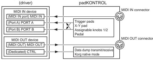
Computer application
MIDI IN device
MIDI IN
MIDI messages received at the padKONTROL's MIDI IN connector are input to this port.
For example this allows MIDI messages from an external sequencer to be received by an application on your computer, and allows the padKONTROL to be used as a USB-MIDI interface. In this case, choose this port in the MIDI input settings of your application.
PORT A/PORT B
MIDI messages from the padKONTROL's various controllers are input to these ports. The "USB-MIDI Port" (p.21-26) specifies the port to which the messages are input. If you're using the padKONTROL to control an application on your computer, select one of these ports in the MIDI Input settings of your application.
MIDI OUT device
MIDI OUT
The MIDI messages transmitted by the software are sent without change to the padKONTROL's MIDI OUT connector. If you're using the padKONTROL as a USB-MIDI interface (for example when sending MIDI messages from a computer application to an external device), select this port in the MIDI output settings of your application.
CTRL
This is used to transmit and receive data dumps, and is used in Korg native mode.
About the padKONTROL's MIDI connectors
When USB is not connected
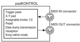
MIDI IN connector
This receives MIDI messages. In Korg native mode, this will receive dedicated system exclusive messages.
MIDI OUT connector
This transmits MIDI messages when you operate the padKONTROL's various controllers.
When USB is connected
MIDI IN connector
This transmits MIDI messages without change to the MIDI IN port.
MIDI OUT connector
MIDI messages sent from the MIDI OUT port are transmitted from this connector without change
About Korg Native mode
In addition to the general-purpose controller functionality already explained, the padKONTROL also has something called "Native mode."
In Native mode the padKONTROL can be used as a controller for software that supports native mode.

In Native mode, the settings made in Setting mode will be ignored. If you want to keep your settings, you must save them before you enter Native mode.

Native mode does not use the concept of Play or Setting modes.

Native mode also supports transmission/reception via the MIDI connectors.

The USB port settings will be different in Native mode.
Operations in Native mode
1 To enter Native mode, make the appropriate settings in your connected software that supports Native mode.
2 Operate the various controllers in the same way as in normal mode.
The function of each key and the assignment of the controllers will be according to the settings of your computer software.
In Native mode, the USB ports transmit the following messages.
Port A: Special messages related to each key and controller
Port B: Note messages and Pitch Bend messages
3 To exit Native mode, make the appropriate settings in your connected software that supports Native mode, or hold down the padKONTROL's [SCENE] key and [MESSAGE/EXIT] key, and press the [SETTING/ENTER] key.
The padKONTROL will return to Play mode.
Normally you should exit Native mode by using the menu of your connected software. If you are unable to exit Native mode from the menu of your software because a cable has been disconnected or for some other reason, use the keys of the padKONTROL to exit Native mode.
Note For details about how to enter and exit Native mode, about the messages that appear in the main display when in Native mode, and about the operations in Native mode, please refer to the owner's manual for your software that supports Native mode.
Troubleshooting
Power does not turn on
- Is the power switch set to the correct position? (p.12)
- Could the padKONTROL be connected to your computer via a hub?
Software does not respond
- Is the USB cable connected correctly?
- Has the padKONTROL been recognized by the connected computer?
If you're using Windows XP, go to Control Panel "Sound and Audio Devices Properties" and check the Hardware settings.
If you're using Mac OS X, go to Macintosh HD Application folder Utility folder "Audio MIDI Settings," and in the "MIDI Devices" tab page, check whether the padKONTROL has been recognized.
Depending on the hardware setup of your computer, it may not be possible for the padKONTROL to be recognized via a USB connection.
- Check the padKONTROL assignments and the USB-MIDI Port assignments.
- It may be that the connected device or software does not support the function you're attempting to use. Refer to the owner's manual of the connected device or software, and make sure that the function is supported.
Trigger pad velocity is not detected
- Check the velocity setting. (p.20)
Sound does not stop
- If a note number is assigned to a trigger pad and the trigger pad is set to Toggle operation, it may be that the corresponding Note-off message was not transmitted. If this occurs, use the Message function to execute [2] ALL NOTE OFF (p.17) or [1] PANIC (p.17).
Specifications
Controllers
Trigger pads × 16 : velocity-sensitive X-Y pad Assignable knobs × 2 Pedal
Display
LED
Memory
User scene memories: 16
Preloaded scene templates: 30
Connectors
Pedal jack
MIDI IN/OUT connectors
USB connector
Power supply jack (DC9V
Power supply
DC9V, AC adapter (optional)
USB bus power (when using the USB connector)
314.2 × 55.1 × 233.6 ~mm / 12.4 × 2.2 × 9.2 inches (including protrusions)
Weight
960 g / 2.1 lbs.
Current consumption
When using USB bus power: 150mA (MAX 180 mA) When using DC9V adapter: 150mA (MAX 180 mA)
■ Included items
USB cable
- CD-ROM (containing padKONTROL Editor/Librarian software etc.)
- Owner's manual
- Software license agreement
Operating requirements for connection to a computer Macintosh
Operating system: Mac OS X 10.2 or later
Computer: Apple Macintosh computer with a USB port, satisfying the operating requirements of Mac OS X
Windows
Operating system: Microsoft Windows XP Home Edition/ Professional
Computer: Computer with a USB port, satisfying the operating requirements of Windows XP (USB chipset made by Intel Corporation is recommended)
■ Options
AC adapter
Pedal switch PS-1
Appearance and specifications of the product are subject to change without notice. (Current as of July 2005)
List of key operations
| Play mode (performing) | |
| Recall a scene | Hold down the [SCENE] key and press a trigger pad [1]...[16] |
| Use the Roll function | Press the [ROLL] key |
| Use the Flam function | Press the [FLAM] key |
| Use the Hold function | Press the [HOLD] key |
| Transmit a program change | Hold down the [PROG CHANGE/WRITE/ALL PAD] key and turn the encoder |
| Transmit a message | Hold down the [MESSAGE/EXIT] key and press a trigger pad [1]...[8] |
| Fix the velocity value | Press the [FIXED VELOCITY/PRELOAD] key |
| Setting mode (editing) | |
| Enter Setting mode | Press the [SETTING/ENTER] key |
| Return from Setting mode to Play mode | Press the [SETTING/ENTER] key |
| Cancel while editing | Press the [MESSAGE/EXIT] key |
| Save a scene | Hold down the [SCENE] key and press the [PROG CHANGEWRITE/ALL PAD] key |
| Setting mode | ||||||
| Key | Trigger Pad | Pedal | X-Y Pad | Knob1/2 | Flam | Roll |
| [NOTE/CC#/LEFT] | Note#[C-1...G9] / CC#[0...127] | Note#[C-1...G9] / CC#[0...127] | Message Type [No Assign/Pitch Bend /After Touch/CC#] | Message Type [No Assign/Pitch Bend /After Touch/CC#] | Interval Left [0...255] | Speed Left [40...240] |
| [MIDI CH/RIGHT] | MIDI CH [Disable/1...16] | MIDI CH [Disable/1...16] | Interval Right [0...255] | Interval Right [40...240] | ||
| [SW TYPE/POLARITY] | Switch Type [Momentary/Toggle] | Switch Type [Momentary/Toggle] | Polarity [Normal/Reverse] | Polarity [Normal/Reverse] | ||
| [REL .VAL./LOWER] | Release Value[0...127] (only if cc is assigned) | Release Value[0...127] (only if cc is assigned) | Release Value [0...127]-128...127] | Volume Lower [1...127] | Expression Lower [1...127] | |
| [VELOCITY/UPPER] | Velocity Curve(Note) On Value[0...127] (cc) | Velocity Curve(Note) On Value[0...127] (cc) | Volume Upper [1...127] | Expression Upper [1...127] | ||
| [PORT] | USB-MIDI Port [PORT A/PORT B] | USB-MIDI Port [PORT A/PORT B] | ||||
KORG
padKONTROL
MIDI Channel [1...16]
Constant Velocity [1...127]
Release Value [0...127]
Note Number [C-1...G9] (C ... G 9)
MIDI Channel [1...16]
Control Change Number [0...127]
(p.115 "MIDI Control Change Messages")
Release Value [0...127]
Control Change Number [0...127]
Release Value [-128...0...127]
Control Change Number [0...127]
LEFT Value [0...255]
LOWER Value [1...127]
UPPER Value [1...127]
LEFT Value [40...240]
LOWER Value [1...127]
UPPER Value [1...127]
Fixed Velocity [1...127]
MIDI Channel [1...16]
Constant Velocity [1...127]
Control Change Number [0...127]
(S.115 „MIDI Control Change Messages“)
Release-Wert [0...127]
MIDI Channel [1...16]
Release Value [0...127]
Release-Wert [0...127]
Control Change Number [0...127]
Release Value [-128...0...127]
Release Value [0...127]
LEFT Value [0...255]
LOWER Value [0...127]
UPPER Value [0...127]
LEFT Value [40...240]
LOWER Value [0...127]
UPPER Value [0...127]
Fixed Velocity [1...127]
| Function | Transmitted | Recognized | Remarks | |
| Basic Channel | Default | 1-16 | 1-16 | Memorized |
| Changed | 1-16 | 1-16 | ||
| Mode | Memorized | × | × | |
| Messages | ○ | × | *1 | |
| Altered | ********** | |||
| Note Number: | True Voice | 0-127 | × | |
| ********** | ||||
| Velocity | Note On | ○1-127 | × | |
| Note Off | ○64 | × | Trigger Pad, Pedal | |
| Aftertouch | Polyphonic (Key) | × | × | Panel Control (Pitch,Mod) |
| Monophonic (Channel) | ○ | × | Panel Control (Pitch,Mod) | |
| Pitch Bend | ○ | × | X-Y Pad, Knob 1/2 *1 | |
| Control Change | 0-127 | ○ | × | Trigger Pad, Pedal, X-Y Pad, Knob 1/2 |
| Program Change Variable Range | 0-127********** | X********** | |
| System Exclusive | ○ | ○ | *1, *2 |
| System Song Position Common | ○ | × | *1, *3 |
| ○ | × | *1, *3 | |
| ○ | × | *1, *3 | |
| System Clock Real Time Command | ○ | × | *1, *3 |
| ○ | × | *1, *3 | |
| Aux Messages Local On/Off All Notes Off Active Sense Reset | ○ | × | *1 |
| ○ | × | *1 | |
| ○ | × | *1 | |
| ○ | × | *1, *3 | |
| Notes *1: Can be transmitted by the message transmission functionality in Play mode. *2: For reception, inquiry messages are supported as well as Korg exclusive messages. *3: Can be assigned using the editor librarian software and transmitted as a Free Message. | |||
| Mode 1: OMNI ON, POLY Mode 2: OMNI ON, MONO O: Yes Mode 3: OMNI OFF, POLY Mode 4: OMNI OFF, MONO X: No Consult your local Korg distributor for more information on MIDI IMPLEMENTATION. Veuillez vous adresser a votre revendeur Korg pour une copie de l'equipement MIDI. Weitere Informationen zur MIDI IMPLEMENTATION erhalten Sie bei Ihrem Handler oder dem Korg-Vertrieb Ihres Landes. | |||
- Precautions
- Location
- Power supply
- Interference with other electrical devices
- Handling
- Care
- Keep this manual
- Keeping foreign matter out of your equipment
- THE FCC REGULATION WARNING (for U.S.A.)
- CE mark for European Harmonized Standards
- IMPORTANT NOTICE TO CONSUMERS
- Introduction
- Main features
- trigger pads
- Pedal jack
- X-Y pad
- Two assignable knobs
- Sixteen user memories
- USB-MIDI interface functionality
- Bus power is supported
- ■ Editor/Librarian softwae is included
- Top and rear panels
- Display
- 2.Encoder
- 3.[SETTING/ENTER]key
- [X]/[Y] keys
- [PEDAL] key
- 6.[NOTE/CC#/LEFT]key
- [MIDI CH/RIGHT] key
- [SW TYPE/POLARITY] key
- [REL. VAL./LOWER] key
- [VELOCITY/UPPER] key
- 11.[PORT]key
- [KNOB 1 ASSIGN]/[KNOB 2 ASSIGN] keys
- Knob 1, Knob 2
- [SCENE] key
- 15.[MESSAGE/EXIT]key
- [FIXED VELOCITY/PRELOAD] key
- [PROG.CHANGE/WRITE/ALL PAD] key
- [HOLD] key
- [FLAM] key
- [ROLL] key
- Trigger pads
- X-Y pad
- USB connector
- MIDI connectors
- Pedal jack
- Power switch
- Power supply connector
- Installing the MIDI driver and software
- Contents of the CD-ROM
- Please read before use
- Windows XP users
- Operating requirements
- Computer
- Supported operating systems
- padKONTROL application installer
- ■ KORG USB-MIDI Driver for Windows XP installation and settings
- Installing KORG USB-MIDI Driver for Windows XP
- ■ Uninstalling KORG USB-MIDI Driver for Windows XP
- Mac OS X users
- Mac OS X MIDI input and output ports
- Input Settings for Applications
- ■ Installing the Editor/Librarian software
- Making connections and turning on the power
- USB connections
- MIDI connections
- About the illumination mode
- Quick start
- Try out the padKONTROL!
- Turn the power on
- Recalling a scene
- As an example, here's how to recall scene number 5.
- Hold down the [SCENE] key.
- Using the Roll function and Flame functions
- Making controller assignments
- Saving a scene
- Using your computer to manage scene sets
- Restoring the factory settings
- Loading a single preloaded scene
- Play mode
- Using the controllers
- Trigger pads
- Display indication
- Pedal
- ■ Assignable Knobs 1/2
- Transmitting a Program Change
- Transmitting MIDI messages
- [1] PANIC
- [2] NOTE OFF
- [3] GMON
- [4]-[8] USER1-5
- Using a fixed velocity
- The Flam function
- The Roll function
- The Hold function
- Shortcuts for assigning messages
- Setting mode
- Assigning a Note message to a trigger pad
- Note Number
- ■ MIDI Channel
- Switch Type
- Release Value
- Velocity Curve / Velocity Level
- Velocity Curve [C-1...C-8]
- Constant Velocity [1...127]
- USB-MIDI Port
- USB Port A (P-R)
- USB Port B (P - b)
- Assigning a Control Change to a trigger pad
- Control Change Number
- Control Change Number [0...127]
- On Value
- Assigning the same parameter value to all of the trigger pads
- Assigning a Note message to the pedal
- Disable (品,S)
- Momentary (□□□)
- Toggle(FCL)
- Velocity
- Velocity [1...127]
- USB Port A (P - R)
- Assigning a Control Change to the pedal
- On Value [0...127]
- Release Value [0...127]
- X-Y Pad settings
- Selecting the trigger pads and/or pedal that will be affected by the X-Y pad
- ■Assigning messages
- No Assign ( F F)
- Pitch Bend (bd)
- AfterTouch (RF)
- Polarity
- Normal (nnn)
- Reverse (rE_U)
- Assignable Knob 1/2 settings
- - Selecting the trigger pads and/or pedal that will be affected by assignable knobs 1/2
- Flam function settings
- What is the Flam function?
- - Selecting the trigger pads and/or pedal that will be enabled
- X-axis setting (interval from the first strike to the second)
- Y-axis setting (velocity of the second strike)
- Roll function settings
- What is the Roll function?
- X-axis setting (roll speed)
- Y-axis setting (roll volume (velocity))
- Fixed Velocity setting
- Appendix
- About the padKONTROL and the driver ports
- MIDI IN device
- MIDI IN
- PORT A/PORT B
- MIDI OUT device
- MIDI OUT
- CTRL
- About the padKONTROL's MIDI connectors
- When USB is not connected
- MIDI IN connector
- MIDI OUT connector
- When USB is connected
- About Korg Native mode
- Operations in Native mode
- Troubleshooting
- Specifications
- List of key operations
- KORG
- padKONTROL
- MIDI Channel [1...16]
- LEFT Value [0...255]
- Fixed Velocity [1...127]
- Release-Wert [0...127]
Brand : KORG
Model : PADKONTROL
Category : MIDI Controller