
AH262S-HD - Hedge Trimmers Shindaiwa - Free user manual and instructions
Find the device manual for free AH262S-HD Shindaiwa in PDF.


| Product type | Hedge trimmer |
| Brand | Shindaiwa |
| Model | AH262S-HD |
| Power source | Gasoline (2-stroke mixture) |
| Displacement | 27.2 cm³ |
| Power | 1.3 kW |
| Blade length | 75 cm |
| Tooth spacing | 25 mm |
| Weight (without fuel) | 5.6 kg |
| Fuel tank capacity | 0.5 L |
| Oil tank capacity | 0.2 L |
| Handle type | Rear and front handle with vibration dampeners |
| Sound level | 94 dB(A) |
| Vibration level | 7.5 m/s² |
| Anti-vibration system | Yes |
| Ignition | Electronic CDI |
| Spark plug | NGK BPMR7A |
| Main functions | Cutting hedges, shrubs, branches up to 25 mm |
| Maintenance | Cleaning after use, blade sharpening, air filter replacement |
| Safety | Safety trigger, anti-shock protection, emergency stop |
| Spare parts | Blades, spark plugs, filters, handles available |
| Repairability | Repairability index 8/10 |
| Manual included | Yes, with detailed operating instructions |
Frequently Asked Questions - AH262S-HD Shindaiwa
User questions about AH262S-HD Shindaiwa
0 question about this device. Answer the ones you know or ask your own.
Ask a new question about this device
Download the instructions for your Hedge Trimmers in PDF format for free! Find your manual AH262S-HD - Shindaiwa and take your electronic device back in hand. On this page are published all the documents necessary for the use of your device. AH262S-HD by Shindaiwa.
USER MANUAL AH262S-HD Shindaiwa
OPERATOR'S MANUAL
ARTICULATED HEDGE TRIMMER
AH262S-HD
Please ensure that you read the operator's manual before using your product.
- Intended use of this product
- shindaiwa Hedge Trimmer are lightweight, high-performance, petrol engined units designed for hedge and shrub trimming.
- Do not use this unit for any purpose other than aforementioned.
○ Users of the product
- You should not use this product until you have read the operator's manual carefully and fully absorbed its content.
- This product should not be used by anyone who has failed to read the operator's manual properly, is suffering from a cold, tiredness or otherwise in poor physical condition, or children.
- Keep in mind that the operator or user is responsible for accidents or hazards occurring to other people or their property.
About your operator's manual
- This manual contains necessary information about the operation and maintenance of your product. Please read it carefully and absorb its contents.
- Always keep your manual in a place where it is readily accessible.
- If you have lost your manual or it is damaged and no longer readable, please purchase a new one from your shindaiwa dealer.
- The units used in this manual are SI units (International System of Units). Figures in parentheses are reference values, and there may be a slight conversion error in some cases.
○ Loaning or assigning your product
- When loaning the product described in this manual to another party, ensure that the person borrowing and working with the product receives the operator's manual along with the product. If you assign your product to another party, please enclose the operator's manual with the product when handing it over.
Enquiries
- Please contact your shindaiwa dealer for requests regarding information about your product, the purchase of consumables, repairs, and other such enquiries.
○ Notices
- The content of this manual may be changed without notice for the purpose of upgrades to the product. Some of the illustrations used may differ from the product itself in order to make the explanations clearer.
• This product requires the assembly of some parts. - Please consult your shindaiwa dealer if anything is unclear or of concern.
○ Feature of this model: Soft Start
- Soft Start generates enough revolving power to rotate crankshaft up to a speed to ignite the engine and bring almost no kickback. Soft Start makes engine start far easier than you ever expect.
- Our goods come with guarantees that cannot be excluded under the Australian Consumer Law. You are entitled to a replacement or refund for a major failure and compensation for any other reasonably foreseeable loss or damage. You are also entitled to have the goods repaired or replaced if the goods fail to be of acceptable quality and the failure does not amount to a major failure.
For warranty service, find the nearest Authorised Service Dealer in our dealer locator map at www.echo australia.com.au/en_au/finder, or by calling 1300 274 447, or by emailing or writing to salesenquires@briggsandstratton.com.au, Briggs & Stratton Australia Pty Ltd, Locked bag 5004, St Clair, NSW 2759.
For safe use of your product....4
Warning notices 4
Other indicators 4
Symbols 4
Location in which the safety decal is attached....6
Handling fuel....7
Handling the engine....7
Handling the product 9
Packing list....13
Description....14
Before you start 15
Assembly 15
Adjusting Cutting Angle 17
Shoulder strap 18
Preparing the fuel 19
Engine operation....20
Starting the engine 20
Stopping the engine....21
Hedge and shrub trimming operation 22
Basic hedge trimming operation 22
Maintenance and care 23
Maintenance and care 23
Storage 29
Long-term storage (30 days or more).... 29
Disposal procedure 30
Specifications....31
Declaration of conformity 32
Be careful to read this section before using your product.
- The precautions described in this section contain important safety information. Please observe them carefully.
- You must also read the precautions that appear in the body of the manual itself.
Text following a [diamond mark] mark describes the potential consequences of failing to observe the precaution.
Warning notices
Situations where there is a risk of physical injury to the operator and other people are indicated in this manual and on the product itself by the following warning notices. Always read and observe them carefully in order to ensure safe operation.

DANGER
WARN
NG

AUTION
This symbol accompanied by the word "DANGER" calls attentions to an act or a condition which will lead to serious personal injury or death of operators and bystanders.
This symbol accompanied by the word "WARNING" calls attentions to an act or a condition which can lead to serious personal injury or death of operators and bystanders.

"CAUTION" indicates a potentially hazardous situation which, if not avoided, may result in minor or moderate injury.
Other indicators
As well as warning notices, this manual uses the following explanatory symbols:

Circle and slash symbol means whatever is shown is prohibited.
NOTE IMPORTANT
This enclosed message provides tips for use, care and maintenance of the product.
Framed text featuring the word "IMPORTANT" contains important information about the use, checking, maintenance and storage of the product described in this manual.
Symbols
In this manual and on the product itself, a series of explanatory symbols is used. Please make sure that you fully understand what each symbol means.
| Symbol form/shape Symbol description/application | Symbol form/shape Symbol description/application | ||
 | Carefully read the operator's manual |  | Petrol and oil mixture |
 | Wear eyes, ears and head protection |  | Purge bulb (Primer) |
 | Safety / Alert Finger severing |  | |
 | Emergency stop |  | Carburettor adjustment- Idle speed |
 | Do not use the product in plac-es with poor ventilation |  | Choke Control"Cold Start"Position(Choke Closed) |
For safe use of your product
| Symbol form/shape Symbol description/application | Symbol form/shape Symbol | description/application |
 | Beware of fire |  Choke Control"Run"Position(Choke Open) Choke Control"Run"Position(Choke Open) |
 | Beware of electric shocks Environmental | 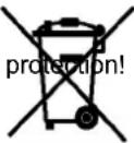 |
 | Beware of high-temperature areas |  Guaranteed sound power level Guaranteed sound power level |
 | Engine start |  This product conducts electricity. Keep the product and/or operator a minimum distance of 10 meters away from electrical source and power lines. This product conducts electricity. Keep the product and/or operator a minimum distance of 10 meters away from electrical source and power lines. |
 | Wear heavy duty, non-slip gloves. |  Safety tip shoes or boots with non-slip sole should be worn. Safety tip shoes or boots with non-slip sole should be worn. |
 | Keep bystanders at least 15 meters away from the operating trimmer to reduce the risk of being struck by falling objects or thrown debris. |  Be aware of the danger of falling debris. Be aware of the danger of falling debris. |
Location in which the safety decal is attached
The safety decal shown below has been attached to the products described in this manual. Ensure that you understand what the decal means before using your product.
If the decal becomes unreadable due to wear and tear or damage, or peels off and is lost, please purchase a replacement decal from your dealer and attach it in the location shown in the illustrations below. Ensure that the decal is readable at all times.

- Safety decal (Part number X505-002890)
Handling fuel

DANGER
Always keep well away from fire when refuelling
Fuel is highly inflammable and leads to a risk of fire if mishandled. Use extreme care when mixing, storing or handling or serious personal injury may result. Be careful to observe the following instructions.
○ Do not smoke or hold a flame near when refuelling.
○ Do not fuel up while the engine is hot or in operation.
◆ If you do so, the fuel could ignite and cause fire, leading to burns.
About the container and refuelling place
○ Use an approved fuel container.
- Fuel tanks/cans may be under pressure.
Always loosen fuel caps slowly allowing pressure to equalize.
○ DO NOT fill fuel tanks indoors.
ALWAYS fill fuel tanks outdoors over bare ground.
Fuel spills can cause fire
Observe the following precautions when refuelling:
Do not add so much fuel that it reaches the mouth of the fuel tank. Keep the fuel within the prescribed level (up to the shoulder level of the fuel tank).
○ Mop up any fuel that overflows or spills out due to overfilling.
○ Tighten the fuel tank cap securely after refuelling.
◆ Fuel spills can cause fire and burns when ignited.

- Fuel tank
- Shoulder level
Do not start the engine in the area where you refue-led
- You must not start the engine in the place where you carried out the refuelling. Move at least 3m from the place where you refueled before starting the engine.
◆ Fuel leaks that occur while refuelling can cause fire if ignited.

Fuel leaks cause fire
○ After refuelling, always check that there are no leaks or discharges of fuel from the fuel pipe, fuel system grommets, or around the fuel tank cap.
If you do find fuel leaks or discharges, stop using the product immediately and contact your dealer to have it repaired.
◆ Any fuel leaks could cause fire.

Handling the engine

DANGER
Keep the trimmer at least 10 meters away from electrical lines or branches that contact electrical lines
The articulated hedge trimmer is not insulated against electrical shock. Keep the trimmer at least 10 meters away from electrical lines or branches that contact electrical lines.
◆ Approaching or contacting electrical lines with the trimmer could cause death or serious injury.


WARNING
Starting the engine
Be particularly careful to observe the following precautions when starting the engine:
○ Always ensure all handles and guards are fitted
○ Check that none of the nuts and bolts are loose
○ Check that there are no fuel leaks
○ Check that the cutter blades is not damaged or excessively worn. If you find any abnormalities, do not use the product.
○ Place the product in a flat, well ventilated place
○ Leave plenty of space around the product and do not allow people or animals near it
○ Remove obstructions, if any
○ Make sure that the cutter blades is not touching the ground or any obstacles
○ Start the engine with the throttle trigger in the idle speed position
○ Hold the product firmly to the ground when starting the engine
Do not start the engine holding the product in the air ◆ Failure to observe the precautions could cause an accide or injury, or even lead to a fatality.
Once the engine has started, check for abnormal vibrations and sounds
Check that there are no abnormal vibrations or sounds once the engine starts. Do not use the product if there are abnormal vibrations or sounds. Contact your dealer to have it repaired.
◆ Accidents involving parts that fall or shatter off can cause wounds or serious injury.
Do not touch high temperature or high voltage components while the product is running
Do not touch the following high temperature or high voltage components while the product is running or for some time after it stops.
Silencer, spark plug, gear housing, and other high temperature components
◆ You could burn yourself if you touch a high temperature component.
○ Spark plug, spark plug wire, and other high voltage components
You could receive an electric shock if you touch a high voltage component while the product is running.

Put safety first in the case of fire or smoke
If fire comes from the engine or smoke appears from any area other than the exhaust vent, first distance yourself from the product to ensure your physical safety.
Use a shovel to throw sand or other such material on the fire to prevent it from spreading, or put it out with a fire extinguisher.
◆ A panicked reaction could result in the fire and other damage becoming more extensive.

Exhaust fumes are toxic
The exhaust fumes from the engine contain toxic gases Do not operate the product indoors or in a plastic greenhouse or in other ill ventilated places.
◆ The exhaust fumes could cause poisoning.

Turn off the engine when checking or maintaining the product
Observe the following precautions when checking and maintaining your product after use:
Turn the engine off and do not attempt to check or maintain the product until the engine has cooled
◆ You could burn yourself.
○ Remove the spark plug cap before performing checks and maintenance
◆ An accident could occur if the product starts unexpectedly.
Checking the spark plug
Observe the following precautions when checking the spark plug.
○ If the electrodes or terminals are worn, or if there are cracks in the ceramics, replace them with new parts.
The spark test (for checking whether the spark plug is sparking) must be carried out by your dealer.
The spark test must not be carried out in proximity of the spark plug hole.
The spark test must not be performed in places where there are fuel spills or inflammable gases
- You must not touch the metal parts of the spark plug
◆ The spark plug could ignite a fire or give you an electric shock.


Handling the product General precautions

WARNING
Operator's manual
- Be careful to read the operator's manual properly before using your product in order to ensure correct operation.
◆ Failure to do so could lead to an accident or serious injury.

Do not use the product for anything other than its intended purpose
- You must not use the product for any purpose other than those described in the operator's manual.
◆ To do so could lead to an accident or serious injury.
Do not modify the product
- You must not modify the product.
To do so could lead to an accident or serious injury. Any malfunction resulting from a modification to the product will not be covered by the manufacturer's warranty.
Do not use the product unless it has been checked and maintained
You must not use the product unless it has been checked and maintained. Always ensure that the product is checked and maintained on a regular basis.
◆ Failure to do so could lead to an accident or serious injury
Loaning or assigning your product
When loaning your product to another party, ensure that the person borrowing the product receives the operator's manual along with it.
○ If you assign your product to another party, please enclose the operator's manual with the product when handing it over.
◆ Failure to do so could lead to an accident or serious injury
Being prepared in case of an injury
In the unlikely event of an accident or injury, please ensure that you are prepared.
○ First aid kit
○ Towels and wipes (to stop any bleeding)
○ Whistle or mobile phone (for calling outside help)
◆ If you are unable to perform first aid or call for outside help the injury could worsen.

Precautions for use

DANGER
Always stop the engine when a blades jam occurs
○ Do not attempt to remove an object causing a blades jam if the engine is running.
◆ Physical injury can occur if a blades jam is removed and the blades starts moving.
Do not remove the blunt extension
Do not operate the product without the blunt extension. If it needs to be removed for the sake of maintenance, consult your dealer.
◆ Failure to comply may result in serious injury.

WARNING
Users of the product
The product should not be used by:
○ people who are tired
○ people who have taken alcohol
○ people who are on medication
○ people who are pregnant
○ people who are in poor physical condition
○ people who have not read the operator's manual
○ children
◆ Failure to observe these instructions could lead to an accident.
The ignition system of this product generates electromagnetic fields during operation. Magnetic fields can cause pacemaker interference or pacemaker failure. To reduce health risks, we recommend that pacemaker users consult their physician and the pacemaker manufacturer before operating this product.

Environment of use and operation
Do not use the product in places where there is no sure foothold, such as on steep slopes or after rainfall, as such places are slippery and dangerous.
○ Maintain footing and balance at all times. Do not stand on slippery, uneven or unstable surfaces. Do not work in odd positions or on ladders. Do not over reach.
Do not operate the product at night or in dark places with poor visibility.
- Heavy protective clothing can increase operator fatigue which may lead to heat stroke. Schedule heavy work for early morning or late afternoon hours when temperatures are cooler.
When cutting a branch that is under tension, be alert for spring-back so that you will not be struck by the moving branch.
◆ A serious injury could result if you fall or slip, or fail to operate the product correctly.
Transport of the product
When transporting in the situations described below, turn off the engine and ensure that the cutter blades has stopped moving, then fit the blade cover and position the silencer away from yourself.
○ Moving to the place where you are working
○ Moving to another area while you are working
○ Leaving the place where you have been working
◆ Failure to observe these precautions could cause burns or serious injury.
When transporting the product by car, empty the fuel tank, fit the blade cover, and secure the product firmly in place to prevent it from moving around.
When carrying the articulated hedge trimmer by hand, the cutter attachment should be pointing backward with the cutter blade in the retracted or transporting position.
◆ Travelling by car with fuel in the fuel tank could lead to a fire
Vibration and cold
It is believed that a condition called Raynaud's Phenomenon which affects the fingers of certain individuals may be brought about by exposure to vibration and cold. Exposure to vibration and cold may cause tingling and burning, followed by loss of colour and numbness in the fingers.
The following precautions are strongly recommended because the minimum exposure which might trigger the ailment is unknown.
Keep your body warm, especially the head and neck, feet and ankles, and hands and wrists.
- Maintain good blood circulation by performing vigorous arm exercises during frequent work breaks, and also by not smoking.
Limit the number of hours of operation.
Try to fill each day with jobs where operating the hedge trimmer or other hand-held power equipment is not required.
If you experience discomfort redness and swelling of the fingers, followed by whitening and loss of feeling, consult your physician before exposing yourself further to cold and vibration.
◆ Failure to observe these instructions could result in damage to your health.
Repetitive stress injuries
It is believed that over-using the muscles and tendons of the fingers, hands, arms and shoulders may cause soreness, swelling, numbness, weakness and extreme pain to the areas just mentioned. Certain repetitive hand activities may put you at a high risk for developing a repetitive stress injury (RSI).
To reduce the risk of RSI, do the following:
- Avoid using your wrist in a bent, extended or twisted position.
Take periodic breaks to minimize repetition and rest your hands. Reduce the speed and force in which you do the repetitive movement.
○ Do exercises to strengthen hand and arm muscles.
See a doctor if you feel tingling, numbness or pain in your fingers, hands, wrists or arms. The sooner RSI is diagnosed, the more likely permanent nerve and muscle damage can be prevented.
◆ Failure to observe these instructions could result in damage to your health.
WARNING
Remove foreign objects and obstructions before working with the product
○ Inspect area that the product will be used in. Remove stones, metal objects and any other object that could jam or damage the product.
◆ An accident or serious injury can occur if foreign objects throw the cutting device.
Turn off the engine immediately if anything goes wrong
In the following situations, turn off the engine immediately and ensure that the cutting device has stopped before checking each area of the product. Replace any damaged parts.
If the cutting device hits a rock, tree, post, or other such obstruction while you work.
○ If the product suddenly starts to vibrate abnormally.
◆ Continuing to use parts when they are damaged could lead to an accident or serious injury.
The area within a 15 m radius is a danger zone
The area within a 15 m radius of the product is a danger zone. Be careful to observe the following precautions while working with the product.
Do not allow children and other people or pets to enter the danger zone.
○ If another person enters the danger zone, turn off the engine to stop the blades.
When approaching the operator, signal to him by, for example, throwing twigs from outside the danger zone, and then check that engine has been switched off and the blades has stopped moving.
- Do not allow anyone to hold the material you are cutting.
◆ Any contact with the cutter blades could cause serious injury.
Do not use the product when the cutter blades is moving at idle speed
- You must not use the product while the cutter blades is moving if the Hedge Trimmer is running with the throttle trigger in the idle speed position. Turn off the engine immediately and adjust the carburettor.
◆ To do so could lead to an accident or serious injury.
Operation
Never remove hands from the product when the blades are moving.
○ Only adjust cutting angle with unit resting flat on the ground, with the switch in the "STOP" position. Never adjust blade angle while standing.
◆ Failure to observe these instructions will cause the product to be held unsteadily and could result in serious injury.
Make sure that the cutter blades is stopped before putting the product on the ground
When you turn off the engine, check to ensure the cutter blades has stopped moving before you lower the product to the ground.
Even if the engine has been turned off, the blades can still cause an injury while free-wheeling.
Remove debris from the silencer
○ If objects such as grasses, leaves, twigs or excessive grease got stuck over the area around the silencer of the engine, stop the engine and remove them paying attention not to touch hot spots.
◆ Failure to do so could lead to a fire.

WARNING
Do not use the product to cut hard objects
Do not use the product to cut hard objects such as wires or steel plates.
If the blades strikes an obstruction or is prevented from functioning properly, stop the engine and inspect the blades for damage.
◆ Failure to follow these instructions could cause breakage of the product or an accident.
Never use the product getting on a ladder or a stool
○ Do not overreach or stand on unstable surfaces.
Do not use the product when being at the top of the ladder or standing on a stool.
◆ Failure to do so could lead to an accident or serious injury.
Protective gear

WARNING
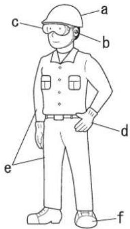
Wear protective gear
Always wear the following protective gear when working with the hedge trimmer.
a Head protection (helmet): Protects the head
b Ear muffs or ear plugs: Protect the hearing
c Safety goggles: Protect the eyes
d Safety gloves: Protect the hands from cold and vibration
e Work clothes that fit (long sleeves, long trousers): Protect the body
f Heavy duty, non-slip protective boots or non-slip work shoes : Protect the feet
◆ Failure to observe these precautions could result in damage to your sight or hearing, or lead to a serious injury.
When necessary, please use the protective gear below.
○ Dust mask: Protects the breathing apparatus
○ Bee net: To deal with attacks by bees
Full face shield: When trimming overhead, wear head protection meeting CE with a full face shield.

Wear proper clothing
Do not wear ties, jewellery, or loose, dangling clothing which could be caught in the unit. Do not wear open toed footwear, or go bare-foot or barelegged.
◆ Failure to observe these precautions could result in damage to your sight or hearing, or lead to a serious injury.

The following parts are packed separately in the packing box.
When you have unpacked the box, please check the parts that it contains.
- Contact your dealer if anything is missing or broken.

- Power head
- Operation shaft
- Blade cover
- Shoulder strap
-
L-wrench
-
Spanner
- Socket wrench
- Operator's manual


- Ignition switch Device for allowing the engine to be started and stopped.
- Throttle trigger lockout Device that prevents the accidental operation of the throttle trigger until manually released.
- Spark plug
- Air cleaner cover Covers air filter.
- Fuel tank cap For closing the fuel tank.
- Fuel tank Contains fuel and fuel filter.
- Fuel tank guard
- Throttle trigger Device activated by the operator's finger, for controlling the engine speed.
- Front grip
- Hand guard Guard between the front handle and cutting device for protecting the hand from injuries if the hand slips off the handle.
-
Outer tube Part of the unit that provides a casing for power transmission shaft.
-
Cutter assembly adjustment lever Provides secure hand grip for adjusting cutting blade angle.
- Hedge trimmer cutter assembly
- Latch lock Fixes the angle of the cutter.
- Latch release Safety device to prevent the latch lock from being released unexpectedly.
- Gear housing assembly Gear housing contains drive gears for transmitting power to cutting blades.
- Cutter bar and cutter blades That part of the assembly of cutter blade and shear plate together with any supporting part, which performs the cutting action.
- Blunt extension An extending blunt part of the cutting device.
- Blade cover When transporting or storing the product always fit the blade cover.
- Suspension point Device on which the strap can be hooked.
- Shoulder strap An adjustable strap to suspend unit.
- Starter handle Pull handle to start the engine.
- Type and serial number
Assembly
WARNING
Read the operator's manual carefully to ensure that you assemble the product correctly.
◆ Using a product that has been incorrectly assembled could lead to an accident or serious injury.

Connect the outer tube to the powerhead

- Spark plug
- Clamp screw
- Tube clamp
- Drive shaft
- Outer tube
- Protective cover

- L-wrench
- Tube clamp
Connect the throttle cable

- Ignition leads
-
Fan cover pocket
-
Place the powerhead on a clean, flat surface, spark plug facing up.
- Slip off the protective cover from the end of the outer tube.
- Use the L-wrench to loosen the tube clamp screw.
- Slide the outer tube into the tube clamp until the tube bottoms. If installation is difficult, rotate the outer tube or main shaft slightly until you feel the drive shaft splines engage with the powerhead.
- Position the outer tube so that the gearcase output shaft is facing left on silencer cover.
- Slide the outer tube into the powerhead until the throttle grip just contacts the tube clamp.
WARNING
○ Ensure that the fuel tank cap is securely in place.
◆ Failure to do so could lead to an injury or serious accident or cause a fire.
CAUTION
○ Do not force the shaft tube into the powerhead.
◆ Excessive force can damage the shaft tube and drive shaft.
-
Tighten the clamp screw firmly.
-
Connect 2 ignition leads from throttle cable tubing to 2 ignition leads on engine.
- Place the connected ignition lead connectors in the fan cover pocket.
CAUTION
○ Wiring runs must not interfere with throttle operation.

- Air cleaner cover
- Air cleaner cover knob

- Throttle cable
- Adjustment fixture
- Throttle swivel hole
- Adjustment nut
- Locknut
- Clip
- Vertical slot

-
Loosen the air cleaner cover knob and remove the air cleaner cover.
-
Place throttle cable into adjustment fixture and install wire end into large carburettor throttle swivel hole.
-
Fit the vertical portion of the clip into the vertical slot to hold down the wire end.
-
The throttle lever free play should be approximately 4-6 mm.
- Turn the adjustment nut in or out as required to obtain proper free play 4-6 mm.
- Make sure that the throttle lever operates smoothly without binding.
- Check throttle for freedom of movement and that wide open throttle / low idle extremes are adjusted properly.
- Tighten locknut.
- Install air cleaner cover.
Adjusting Cutting Angle

DANGER
- Never adjust cutting assembly with engine running.
◆ Failure to do so could lead to an injury or serious accident.

WARNING
○ Hedge trimmer blades are sharp. Always wear gloves when adjusting cutting assembly.
○ Wear heavy duty gloves when working with the hedge trimmer blades. When replacing the hedge trimmer blades during a trimming task, ensure that the engine is switched off and that the blades have stopped.
○ Do not stand hedge trimmer on end when adjusting cutting angle, otherwise serious injury may result.
Gear case assembly becomes HOT during use. Always grip assembly at blade-adjustment handle when making cutting angle adjustments, otherwise serious injury may result.
◆ Failure to do so could lead to an injury or serious accident.
Adjusting the hedge trimmer cutter assembly

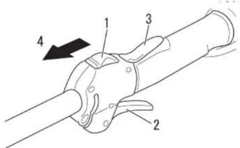
- Adjustment lever
- Latch release

- Latch lock

- Adjustment lever
-
Blade cover
-
Position the hedge trimmer on a flat, level surface with the engine resting on the fuel tank guard. Make sure the blade cover is in place on the blade.
- With your right hand, grasp the outer tube near the handle. With your left hand, grip the adjustment lever on the cutter assembly. With the index finger of your left hand, press the latch release. With your left thumb, press the latch lock.
- While holding the latch release down, pivot the cutter assembly using the adjustment lever until it is at the desired cutting angle.
- Release the latch lock and the latch release. Make sure the latch lock and the latch release return securely to the straight ahead position.
- Remove the blade cover from the cutter blade. The engine now may be started.
IMPORTANT
The latch release provides an interlock to help prevent inadvertent depression of the latch lock.

CAUTION
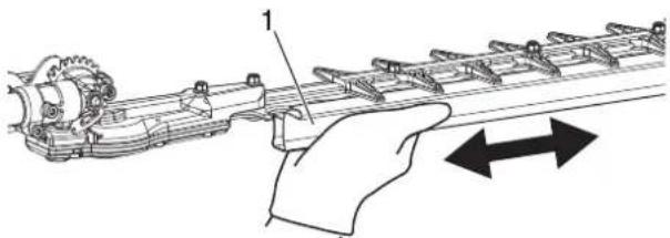
When installing and removing the blade cover from the cutter blade, hold the handle under the blade cover.
◆ Failure to observe these precautions could lead to injury.
Cutter assembly position


- Blade cover
The cutter assembly can be adjusted to ten different positions ranging from 135° to 270° from the outer tube as shown. Always make sure the lock latch is securely locked after each adjustment.
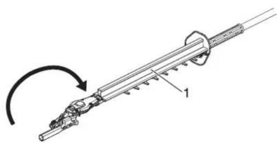
Adjusting for Storage or Transportation
- With the engine off, install the blade cover onto the blade.
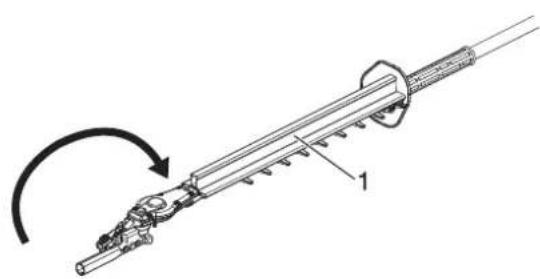
- Rotate the cutter assembly so it is parallel to the tube.
- Make sure the latch lock return securely to a locking position.
- Make sure the blade cover is in place on the cutters before storing or transporting.

WARNING
Never run the engine when adjusting the cutter assembly to the storage position.
Shoulder strap


- Hook the strap hook to the hanger on the outer tube.
- Wear the shoulder strap so that the hook stays at your right hand side.
- Adjust the length of the shoulder strap so that you can hold and operate the machine comfortably.
IMPORTANT
Adjust the shoulder strap or harness so the shoulder pad rests comfortably on the off-side shoulder. Make sure all hooks and adjustment devices are secure.
Emergency Release
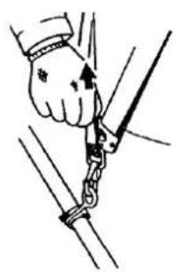
*In case of emergency, strongly pull the white tab at the hook. The machine will be released from the strap.
Preparing the fuel

DANGER
- Fuel is highly inflammable and there is a risk of fire if it is handled incorrectly. Carefully read and observe the precautions in the section of this manual titled "For safe use of your product".
Once the refuelling is complete, securely tighten the fuel tank cap and do not forget to check that there are no leaks or discharges of fuel from the fuel pipe, fuel system grommets, or around the fuel tank cap. If you do find fuel leaks or discharges, stop using the product immediately and contact your dealer to have it repaired.
◆ If the fuel ignites, it could cause burns and fire.


CAUTION
There is difference in pressure between the fuel tank and the outside air. When refuelling, loosen the fuel tank cap slightly to eliminate the difference in pressure.
◆ Otherwise, fuel may get spewed.
NOTE
Stored fuel ages. Do not mix more fuel than you expect use in thirty (30) days. Do not mix directly in fuel tank.
Fuel

Fuel supply

-
Fuel tank 2. Shoulder level
-
Fuel is a mixture of regular grade petrol and an air-cooled 2-stroke engine oil.
Minimum 89 Octane unleaded petrol is recommended. Do not use fuel containing methyl alcohol or more than 10 % of ethyl alcohol. - Recommended mixture ratio; 50 : 1 (2 %) for ISO-L-EGD Standard (ISO 13738), JASO FC, FD grade and Shindaiwa recommended oil.
- Never use two-stroke oil intended for water-cooled engines, motor-cycle engines.
- Do not mix directly in engine fuel tank.
- Avoid spilling petrol or oil. Spilled fuel should always be wiped up.
- Handle petrol with care, it is highly inflammable.
-
Always store fuel in approved container.
-
Fill the fuel tank outdoors over bare ground and install the fuel cap securely. Do not pour fuel indoors.
- Place the product and the refuelling tank on the ground when performing the refuelling operation. Do not refuel the product on the loading platform of a truck, or in other such places.
• Always ensure that the fuel level remains below the shoulder level of the fuel tank when refuelling. - There is a difference in pressure between the fuel tank and the outside air. When refuelling, loosen the fuel tank cap slightly to eliminate the difference in pressure.
• Always wipe up any fuel spills. - Move at least 3m away from where you refueled before you start the engine.
- Keep the refuelling tank in a shaded area away from fire.
Starting the engine

WARNING
When starting the engine, observe the precautions described from Page 4 in the section "For safe use of your product" to ensure that you operate the product correctly.
The attachment will operate immediately when the engine starts and could result in loss of control and possible serious injury. Keep movable parts of the attachment off the ground and away from objects that could become entangled or thrown.
○ If the blades moves even though the throttle trigger is in the idle speed position when the engine is started, adjust the carburettor before using the product.
- Blades will start moving as engine attains clutch engagement speed.
◆ Failure to observe the precautions could cause an accident or injury, or even lead to a fatality.
NOTE
- Pull out the starter handle gently at first, and then more rapidly. Do not pull the starter rope out to more than 2/3 of its length.
Do not let go of the starter handle as it returns.
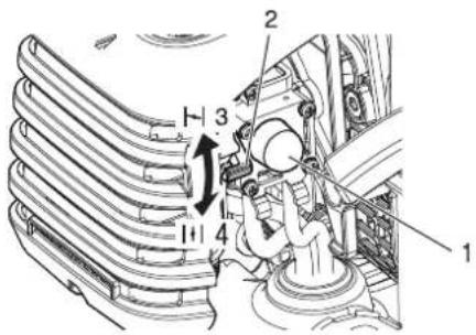
Starting a cold engine
-
Ignition switch
-
Throttle trigger lockout
-
Throttle trigger
-
Start
-
Purge bulb
-
Cold Start
-
Choke lever
-
Run
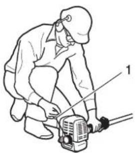
- Starter handle
(Connect the spark plug cap if the product has been in storage for a long period of time)
The starting procedure depends on whether the engine is cold or warm. A cold engine is started as follows.
- Remove the blade cover and check the cutter blades. If anything is wrong, replace it with a new one.
- Placing the product on level ground, check to ensure that the blades does not come into contact with the surface of the ground or any other impediment using a beam or other such implement.
- Check that there are no fuel leaks.
- Move the ignition switch to the Start position.
- Move the choke lever to the "Cold Start" position.
-
Alternately press and release the purge bulb until the fuel is sucked up into it.
-
Checking that the area around you is safe, hold the rear grip firmly with your left hand as shown in the illustration, pulling several times on the starter handle.
- If you hear an explosion-like sound and the engine stops immediately, move the choke lever to the "Run" position and continue pulling on the starter handle to start the engine.
- If the engine starts immediately when you carry out the instructions in step 7, above, return the choke lever gently to the "Run" position.
- Leave the engine to warm up at idle speed for a while.
- Depress the throttle trigger lockout and gradually squeeze the throttle trigger.
Engine warm-up
Starting a warm engine

-
Ignition switch
-
Throttle trigger lockout
-
Throttle trigger
-
Start

-
Choke lever
-
Run
-
Cold Start
Stopping the engine

-
Ignition switch
-
Stop
-
Throttle trigger
-
Once the engine starts, allow it to warm up for 2 to 3 minutes at idling (i.e. low speed).
-
Warming the engine helps to lubricate its internal workings more smoothly. Allow the engine to warm up fully, especially when it is cold.
-
Move the ignition switch to the Start position.
-
Make sure that the throttle trigger is at the idle speed position.
-
Check that the choke lever is in the "Run" position.
- If fuel tank is not empty, pull on the starter handle to start the engine.
- If no fuel is visible in the purge bulb, alternately press and release the purge bulb until the fuel is sucked up into it.
-
Checking that the area around you is safe and pull on the starter handle to start the engine.
-
Release the throttle trigger and set the engine to idling (i.e. low speed).
- Move the ignition switch to the Stop position.
- In the event of an emergency, stop the engine immediately using the ignition switch.
- If the engine fails to stop, move the choke lever to the "Cold Start" position. The engine will stall and come to a halt (a choke stop).
*If the engine fails to stop when the ignition switch is used, have the ignition switch checked and repaired by your dealer before you use the product again.

WARNING
The cutting attachment can continue moving after the engine is stopped.
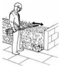
Basic hedge trimming operation
NOTE
- This product is designed to cut shrubs and hedges with branches no larger than 6 mm in diameter.
When starting to trim, run the engine at full throttle. Cutting at less than full speed can damage the clutch by allowing it to slip. When you do not conduct trimming or cutting work, do not run the engine at full throttle.
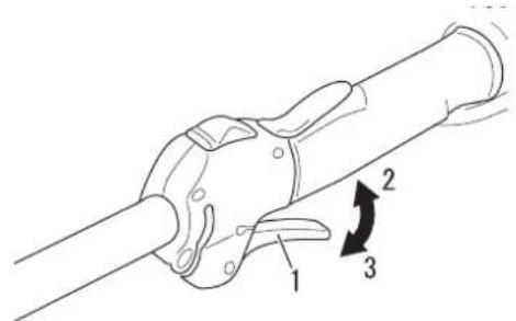
- Throttle trigger
- High speed
- Idling
Pulling the throttle trigger after the engine is started will cause the engine speed to rise and the cutter blades to start moving. Adjust the engine speed depending on, for example, the amount of the hedges to be cut.
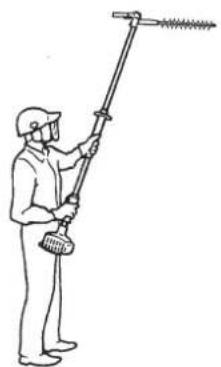
Working Position
- Hold the control handle with your right hand, and the front grip with your left hand.
- Your left arm should be extended to the most comfortable position.
Useing the Hedge Trimmer
Preparations
- Use lopping shears to cut thick branches first.
Cutting Sequence
- If a radial cut is necessary, cut a little at a time in several passes.
Cutting Techniques
- Vertical cut:
- Swing the blade up and down in an arc as you move along the hedge. Use both sides of the cutting blade.
- Cut without standing directly next to the hedge, e.g. with a flower bed between operator and hedge.
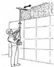
○ Overhead Cut:
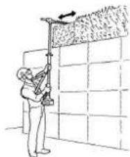
- Hold the shaft upright with a 90° blade angle to cut an upper surface of a hedge.
○ Horizontal Cut:
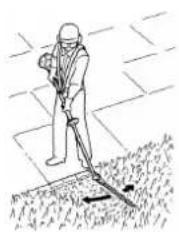
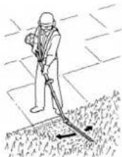
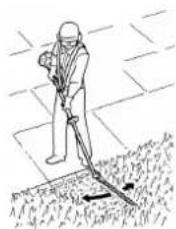
- Hold the cutting blade at an angle of 0° to 10° as you swing the hedge trimmer horizontally.
- Swing the blade in an arc towards the outside of the hedge so that the cuttings are swept on to the ground.
- Cut without standing directly in front of the hedge, e.g. reach over a flower bed.
- Cut close to the ground from a standing position, e.g., for low shrubs.



Maintenance and care
If you have any questions or problems, please contact your dealer.
General maintenance
IMPORTANT
Maintenance, replacement, or repair of emission control devices and system may be performed by any repair establishment or individual. However, warranty repairs must be performed by a dealer or service center authorized by YAMABIKO CORPORATION and use of parts that are not equivalent in performance and durability to authorized parts may impair the effectiveness of the emission control system and may have a bearing on the outcome of the warranty claim.

WARNING
○ Non-standard accessories, cutting attachment, or replacement parts may not operate properly with your unit and may cause damage and lead to personal injury.
Before performing any maintenance, repair, or cleaning work on the unit, make sure the engine and cutting attachment are completely stopped. Disconnect the spark plug wire before performing service or maintenance.
○ Operating the engine without a silencer, or with a silencer that is damaged or improperly installed, can increase engine noise sufficiently to cause hearing loss.
Silencer
This unit must never be operated with a faulty or missing spark arrester or silencer. Make sure the silencer is well secured and in good condition. A worn or damaged silencer is a fire hazard and may also cause hearing loss.
Spark plug
Keep the spark plug and wore connections tight and clean.
Fasteners
Make sure nuts, bolts, and screw (except carburettor adjusting screws) are tight.
Carburettor adjustment

WARNING
When carburettor adjustment is completed, cutter blade should not move at idle, otherwise serious personal injury may result.

CAUTION
When starting, idle speed adjuster (T) should be adjusted not to move the cutter blade. When there is some trouble with the carburettor, contact your dealer.

T: Idle speed adjuster
Every unit is test run at the factory and the carburettor is fine tuned for maximum performance.
Before adjusting carburettor, clean or replace air filter, start engine and run several minutes to bring it to operating temperature.
- Idle Speed Adjustment.
Start engine and turn idle speed adjustment screw (T) clockwise until the blades begin to move, then turn the screw (T) anticlockwise until the blades stop moving. Turn screw (T) anticlockwise an additional 1/2 turn.
- Accelerate to full throttle for 2 to 3 seconds to clear excess fuel from engine then return to idle. Accelerate to full throttle to check for smooth transition from idle to full throttle.
Daily Maintenance

- Cooling fins
10-Hour Maintenance

- Air filter
- Cleaner cover knob
- Air cleaner cover
10/15-Hour Maintenance

a: 0.6 - 0.7 mm
Prior to each work day, perform the following:
- Remove all dirt and debris from the engine, check the cooling fins and air cleaner for clogging, and clean as necessary.
- Carefully remove any accumulations of dirt or debris from the silencer and fuel tank. Check cooling air intake area at base of crankcase. Remove all debris. Dirt build-up in these areas can lead to engine overheating, fire, or premature wear.
- Lubricate the blade before use and after refueling. Check the cutter for damage or incorrect adjustment.
WARNING
○ Always wear gloves when working around the cutter assembly.
◆ Failure to observe the precautions could cause an accident or injury, or even lead to a fatality.
- Clean any debris or dirt from the cutting attachment.
- Check for loose or missing screws or components. Make sure the cutter attachment is securely fastened.
- Check the entire unit for leaking fuel or grease.
-
Make sure nuts, bolts, and screws (except carburetor idle speed adjusting screws) are tight.
-
Close choke. Loosen cleaner cover knob and remove air cleaner cover and air filter.(air filter is located inside air cleaner cover)
-
Brush dirt from filter or clean with compressed air.
-
Reinstall air filter with cover, after installing air filter to cover.
-
Tighten air cleaner cover knob.
CAUTION
Never operate the unit if the air cleaner assembly is damaged or missing.
Remove and clean or replace the spark plug
- Check plug gap. Correct gap is 0.6 mm to 0.7 mm.
• Inspect electrode for wear. - Inspect insulator for oil or other deposits.
- Replace plug if needed and tighten to 10 N·m - 15 N·m (100 kgf·cm to 150 kgf·cm).
15/20-Hour Maintenance

- Gearcase grease fittings
-
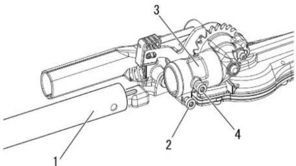
Outer tube
-
Gearcase
-
Gearcase clamp bolt
-
Index bolt

- Drive shaft
Gearcase lubrication
- Clean dirt from grease fitting.
- Lubricate the cutter assembly gearbox by pumping one or two strokes of lithium-base grease into the grease fitting using a lever-type grease gun.

CAUTION
○ Over lubricating can cause the gearcase to operate sluggishly and can cause grease to leak out.
Drive shaft lubrication
- Loosen the gearcase clamp bolt.
- Remove the index bolt from gearcase.
-
Remove the outer tube from the gear housing.
-
Pull the drive shaft from the outer tube, and wipe clean. Recoat with a thin coating 10 to 20 g, of lithium base grease.
- Slide the drive shaft back into the outer tube, being careful not to get dirt on the drive shaft.
- Align the screw hole in gear case with the locating hole in outer tube, install and tighten index bolt, and tighten gearcase clamp bolt.
50-Hour Maintenance
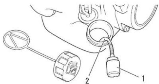
- Fuel filter 2. Fuel line
Cleaning silencer
Cylinder cooling fins
- Remove and clean the cylinder cover and clean dirt and debris from the cylinder cooling fins.
Remove and replace the fuel filter
- Use a piece of metal wire or the like to pick up fuel filter through fuel tank opening.
• Pull old filter from fuel line.
• Install new fuel filter.
NOTE
If filter is excessive dirty or no longer fits properly, replace it.

WARNING
Never operate the unit with a damage or missing silencer or spark arrester. Operating with a missing or damaged spark arrester is a fire hazard, and could also damage your hearing.
- Carbon deposits in silencer will cause a drop in engine output and overheating. Spark arrestor screen must be checked periodically. Clean deposits from silencer.
IMPORTANT
Do not remove the silencer cover. If necessary, Please consult your dealer.
Care for cutting blades

CAUTION
○ Wear gloves to protect hands from sharp blades.
◆ Failure to observe these precautions could lead to injury.
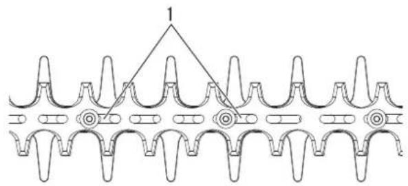
- Bolt slots
Lubricating blades (Every 4 hours of operation)
Apply a few drops of oil the each bolt slots at the bottom of blades.

- Bolt
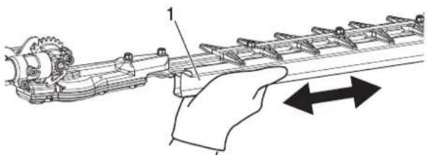
Cleaning blades (After each use)
Remove gummy residue from blades with a 50 : 50 mixture of kerosene (paraffin) and machine oil.
Cutter blade adjustment
Standard blades require no periodic adjustments. Make sure all blade bolts are tight and in good condition.
Troubleshooting table
| Problem Diagnosis Cause Solution | |||
| The engine does not start | There is no fuel in the fuel tankThe ignition switch is in the Stop positionExcess fuel suctionElectrical faultCarburettor malfunction or internal stickingInternal engine malfunction | Fuel supplyMove to the Start positionStart the engine after servicingConsult your dealerConsult your dealerConsult your dealer | |
| Engine is difficult to start, fluctuating rotation | Fuel is entering the overflow pipe | Fuel degradationCarburettor problem | Replace with new fuelConsult your dealer |
| No fuel is entering the overflow pipe | Fuel filter is cloggedFuel system is cloggedInternal carburettor parts sticking | Clean or replaceConsult your dealerConsult your dealer | |
| The spark plug is dirty or damp | Fuel degradationIncorrect electrode gapCarbon depositsElectrical fault | ReplaceReplaceReplaceConsult your dealer | |
| Engine starts but no acceleration is possible | Dirty air filterDirty fuel filterBlocked fuel passageCarburettor adjustment problemBlocked exhaust vent or silencer vent | Clean or replaceClean or replaceConsult your dealerAdjustClean | |
| The engine stops | Carburettor adjustment problemElectrical fault | AdjustConsult your dealer | |
| The engine fails to stop | Ignition switch malfunction | Perform an emergency stop and consult your dealer | |
| The cutter blades moves when the engine is idling | Carburettor adjustment problemDamaged clutch spring | AdjustConsult your dealer | |
| The cutter blades gets blunt | Worn cutter bladesBig gap between upper blade and lower bladeSlippage of the clutch | Consult your dealerConsult your dealerConsult your dealer |
- Checking and maintenance requires specialist knowledge. If you are unable to check and maintain the product or deal with a fault yourself, consult your dealer. Do not attempt to dismantle the product.
- Consult your dealer in the event of a problem that is not covered in the table above, or other such concerns.
For spare parts and consumables, please use only genuine parts and designated products and components. Using parts from other manufacturers or non-designated components may result in a malfunction.
| NOTE |
| Soft Start (See page 2)When starter handle cannot be pulled lightly, the trouble is diagnosed as failure of engine inside.Please consult your dealer.If disassembled inadvertently, it can cause injury. |
Long-term storage (30 days or more)

WARNING
Do not store in sealed locations filled with fuel gas, or close to naked flames or sparks.
◆ You could cause a fire.

When storing the product for long periods of time (30 days or more), ensure that the following preparations for storage are carried out.

-
Ignition switch
-
Stop
-
Throttle trigger
-
Drain the fuel tank completely outdoors over bare ground. Do not drain fuel indoors.
A. Alternately press and release the purge bulb a number of times to remove the fuel from the purge bulb.
B. Start the engine and run it at idle speed until it comes to a natural stop.
-
Move the ignition switch to the Stop position.
-
Wipe clean any grease, oil, dust, dirt and other materials on the outside of the hedge trimmer.
-
Perform the periodic checks prescribed in this manual.
-
Check that the screws and nuts are tightened. Tighten up any that are loose.
-
Remove the spark plug and add the appropriate quantity (around 10 mL) of clean, new 2-stroke engine oil to the cylinder via the installation socket.
A. Place a piece of clean cloth over the spark plug installation socket.
B. Pull 2 or 3 times on the starter handle to distribute the engine oil into the cylinder.
C. Observe the piston location through the spark plug hole. Pull the recoil starter handle slowly until the piston reaches the top of its travel and leave it there.
-
Fit the spark plug. (Do not connect the spark plug cap.)
-
Lubricate the blades with a heavy coat of oil to prevent rust.
-
Once the product is sufficiently cool and dry, fit the blade cover onto the cutter blades and wrap the engine section in a plastic bag or other covering before putting them in storage.
-
Store the product in a dry, dust free place, out of the reach of children and other unauthorized persons.
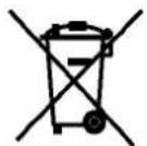
- Dispose of waste oil in accordance with local regulations.
• Major plastic parts making up the product have codes showing their materials.
The codes refer to the following materials; dispose of those plastic parts in accordance with local regulations.
| Mark Material | |
| >PA6-GF< Nylon 6 - | Glass fiber |
| >PP-GF< Polypropylene - | Glass fiber |
| >PE-HD< Polyethylene |
- Please contact your dealer in case you do not know how you should dispose of waste oil / plastic parts.
| AH262S-HD | ||
| External dimensions: Length x Width x Height mm 2440 | × 273 × 260 | |
| Masses:Unit with specified cutting attachment, empty tank kg 6.6Unit with specified cutting attachment, full tank kg 7.0 | ||
| Volume: Fuel tank cm3 600 | ||
| Fuel: Regular grade petrol. Minimum 89 Octane unleadedOil Two stroke, air-cooled engine oil. ISO-L-EGD Stand-Mixing ratio 50: 1 part (2%) | petrol is recommended. Do not use fuel containing methyl alcohol or more than 10% of ethyl alcohol.ard (ISO 13738), JASO FC/FD grade and Shindaiwa recommended oil. | |
| Cutting attachment:Type Dual action, double sided bladeCutting length mm 536Pitch mm 35Height mm 21 | ||
| Gear ratio and lubrication: 4.60 reduction and good quality lithium grease | ||
| Engine:Type Air-cooled two stroke, single cylinderCarburettorMagnetoSpark PlugStarterPower transmissionEngine displacementMaximum shaft brake power (ISO 8893)Fuel consumption at maximum engine powerRecommended maximum engine speed (With STD attachment installed)Recommended engine idling speed | cm3 25.4kWL/hmin−1min−1 | Diaphragm typeFlywheel magneto: CDI systemNGK CMR7HRecoil starterAutomatic Centrifugal clutch1.00.61115003000 |
| Vibration levels: (ISO 22867) ahv,eqFront handle / Rear handleUncertainty: K | m/s2m/s2 | 7.3 / 7.15.0 |
| Sound pressure level: (ISO 22868) LpAd(=LpAeq +KpA)Uncertainty: KpA | dB (A)dB (A) | 96.62.5 |
| Sound power level: (ISO 22868) LWAd(=LWARa +KWA)Uncertainty: KWA | dB (A)dB (A) | 109.92.5 |
These specifications are subject to change without notice.
The undersigned manufacturer:
YAMABIKO CORPORATION
1-7-2 Suehirocho, Ohme, Tokyo 198-8760 JAPAN
This declaration of conformity is issued under the sole responsibility of the manufacturer.
Declares that the hereunder specified new unit:
PORTABLE HEDGE TRIMMER
Brand: shindaiwa
Type: AH262S-HD

Complies with:
* the requirements of Directive 2006/42/EC (use of harmonized standard EN ISO 10517: 2019)
* the requirements of Directive 2014/30/EU (use of harmonized standard EN ISO 14982: 2009, EN 55012: 2007+AI: 2009)
* the requirements of Directive 2011/65/EU (use of harmonized standard EN IEC 63000: 2018)
* the requirements of Directive 2000/14/EC
Conformity assessment procedure followed ANNEX V
Measured sound power level: 107 dB(A)
Guaranteed sound power level: 110 dB(A)
Serial Number 38001001 to 38100000
Serial Number U19038001001 to U19038100000
Tokyo, July 1st, 2021
YAMABIKO CORPORATION

The authorized representative in Europe who is authorized to compile the technical file.
Company: CERTIFICATION EXPERTS B.V.
Address: Amerlandseweg 7, 3621 ZC Breukelen, The Netherlands
Hisashi Kobayashi Mr. Richard Glaser
General Manager
Quality Assurance Dept.
MEMORANDUM
YAMABIKO CORPORATION
1-7-2 Suehirocho, Ohme, Tokyo 198-8760 JAPAN
PHONE: 81-428-32-6118. FAX: 81-428-32-6145.
shindaiwa®
GB
X750234-4604

MANUEL D'UTILISATION
TAILLE-HAIE ARTICULE AH262S-HD

- Levier de réglage


- Poignée de lanceur


Entretien
- Arbre de transmission
- Fentes de boulons
- Boulon
Guide de dépannage
Est conforme :
BEDIENUNGSANLEITUNG
SCHWENKBARE HECKENSCHERE
AH262S-HD
- Verriegelung

- Einstellhebel
- Messerabdeckung

- Startergriff

- Kühlrippen
- Antriebswelle
50-Stunden-Wartung

- Schraubenschlitze
- Schraube
Fehlerbehebung
Folgendes erfüllt:
MANUALE PER L'OPERATORE
TAGLIASIEPI ARTICOLATO AH262S-HD
Gestione del motore
PERICOLO
- Leva di regolazione


- Serbatoio del carburante
- Livello


- Albero motore
- Bullone
Problemi tecnici
È conforme a:
Precauciones de uso

PELIGRO
- Cable del acelerador
- Elemento de ajuste
- Orificio de giro del acelerador
- Tuerca de ajuste
- Contratuerca
- Clip
- Ranura vertical

- Palanca de ajuste




- Eje de transmisión
- Filtro de combustible 2. Tubo de combustible
- Ranuras para tornillos
- Perno
Cumple con:



- OPERATOR'S MANUAL
- ARTICULATED HEDGE TRIMMER
- AH262S-HD
- PLEASE ENSURE THAT YOU READ THE OPERATOR'S MANUAL BEFORE USING YOUR PRODUCT
- INTENDED USE OF THIS PRODUCT
- ○ USERS OF THE PRODUCT
- ABOUT YOUR OPERATOR'S MANUAL
- ○ LOANING OR ASSIGNING YOUR PRODUCT
- ENQUIRIES
- ○ NOTICES
- ○ FEATURE OF THIS MODEL: SOFT START
- BE CAREFUL TO READ THIS SECTION BEFORE USING YOUR PRODUCT
- WARNING NOTICES
- DANGER
- WARN
- NG
- AUTION
- OTHER INDICATORS
- NOTE IMPORTANT
- SYMBOLS
- FOR SAFE USE OF YOUR PRODUCT
- LOCATION IN WHICH THE SAFETY DECAL IS ATTACHED
- HANDLING FUEL
- ALWAYS KEEP WELL AWAY FROM FIRE WHEN REFUELLING
- ABOUT THE CONTAINER AND REFUELLING PLACE
- FUEL SPILLS CAN CAUSE FIRE
- DO NOT START THE ENGINE IN THE AREA WHERE YOU REFUE-LED
- FUEL LEAKS CAUSE FIRE
- HANDLING THE ENGINE
- WARNING
- STARTING THE ENGINE
- ONCE THE ENGINE HAS STARTED, CHECK FOR ABNORMAL VIBRATIONS AND SOUNDS
- DO NOT TOUCH HIGH TEMPERATURE OR HIGH VOLTAGE COMPONENTS WHILE THE PRODUCT IS RUNNING
- PUT SAFETY FIRST IN THE CASE OF FIRE OR SMOKE
- EXHAUST FUMES ARE TOXIC
- TURN OFF THE ENGINE WHEN CHECKING OR MAINTAINING THE PRODUCT
- CHECKING THE SPARK PLUG
- HANDLING THE PRODUCT GENERAL PRECAUTIONS
- DO NOT USE THE PRODUCT FOR ANYTHING OTHER THAN ITS INTENDED PURPOSE
- DO NOT MODIFY THE PRODUCT
- DO NOT USE THE PRODUCT UNLESS IT HAS BEEN CHECKED AND MAINTAINED
- LOANING OR ASSIGNING YOUR PRODUCT
- BEING PREPARED IN CASE OF AN INJURY
- PRECAUTIONS FOR USE
- ALWAYS STOP THE ENGINE WHEN A BLADES JAM OCCURS
- DO NOT REMOVE THE BLUNT EXTENSION
- USERS OF THE PRODUCT
- ENVIRONMENT OF USE AND OPERATION
- TRANSPORT OF THE PRODUCT
- VIBRATION AND COLD
- REPETITIVE STRESS INJURIES
- REMOVE FOREIGN OBJECTS AND OBSTRUCTIONS BEFORE WORKING WITH THE PRODUCT
- TURN OFF THE ENGINE IMMEDIATELY IF ANYTHING GOES WRONG
- THE AREA WITHIN A 15 M RADIUS IS A DANGER ZONE
- DO NOT USE THE PRODUCT WHEN THE CUTTER BLADES IS MOVING AT IDLE SPEED
- OPERATION
- MAKE SURE THAT THE CUTTER BLADES IS STOPPED BEFORE PUTTING THE PRODUCT ON THE GROUND
- REMOVE DEBRIS FROM THE SILENCER
- DO NOT USE THE PRODUCT TO CUT HARD OBJECTS
- NEVER USE THE PRODUCT GETTING ON A LADDER OR A STOOL
- PROTECTIVE GEAR
- WEAR PROTECTIVE GEAR
- WEAR PROPER CLOTHING
- ASSEMBLY
- CONNECT THE OUTER TUBE TO THE POWERHEAD
- CONNECT THE THROTTLE CABLE
- CAUTION
- ADJUSTING CUTTING ANGLE
- ADJUSTING THE HEDGE TRIMMER CUTTER ASSEMBLY
- IMPORTANT
- CUTTER ASSEMBLY POSITION
- ADJUSTING FOR STORAGE OR TRANSPORTATION
- SHOULDER STRAP
- EMERGENCY RELEASE
- PREPARING THE FUEL
- NOTE
- FUEL
- FUEL SUPPLY
- STARTING A COLD ENGINE
- ENGINE WARM-UP
- STARTING A WARM ENGINE
- STOPPING THE ENGINE
- BASIC HEDGE TRIMMING OPERATION
- WORKING POSITION
- USEING THE HEDGE TRIMMER
- PREPARATIONS
- CUTTING SEQUENCE
- CUTTING TECHNIQUES
- MAINTENANCE AND CARE
- GENERAL MAINTENANCE
- SILENCER
- SPARK PLUG
- FASTENERS
- CARBURETTOR ADJUSTMENT
- DAILY MAINTENANCE
- 10-HOUR MAINTENANCE
- 10/15-HOUR MAINTENANCE
- REMOVE AND CLEAN OR REPLACE THE SPARK PLUG
- 15/20-HOUR MAINTENANCE
- GEARCASE LUBRICATION
- DRIVE SHAFT LUBRICATION
- 50-HOUR MAINTENANCE
- CLEANING SILENCER
- CYLINDER COOLING FINS
- REMOVE AND REPLACE THE FUEL FILTER
- CARE FOR CUTTING BLADES
- LUBRICATING BLADES (EVERY 4 HOURS OF OPERATION)
- CLEANING BLADES (AFTER EACH USE)
- CUTTER BLADE ADJUSTMENT
- LONG-TERM STORAGE (30 DAYS OR MORE)
- COMPLIES WITH
- YAMABIKO CORPORATION
- MEMORANDUM
- MANUEL D'UTILISATION
- TAILLE-HAIE ARTICULE AH262S-HD
- ENTRETIEN
- EST CONFORME
- BEDIENUNGSANLEITUNG
- SCHWENKBARE HECKENSCHERE
- 50-STUNDEN-WARTUNG
- FOLGENDES ERFÜLLT
- MANUALE PER L'OPERATORE
- TAGLIASIEPI ARTICOLATO AH262S-HD
- GESTIONE DEL MOTORE
- PERICOLO
- È CONFORME A
- PRECAUCIONES DE USO
- PELIGRO
- CUMPLE CON
Brand : Shindaiwa
Model : AH262S-HD
Category : Hedge Trimmers