EKWHCTRL0 - Thermostat DAIKIN - Free user manual and instructions
Find the device manual for free EKWHCTRL0 DAIKIN in PDF.


| Product Type | Thermostat |
| Brand | Daikin |
| Model | EKWHCTRL0 |
| Dimensions (HxWxD) | 86 x 86 x 30 mm |
| Weight | Approx. 150 g |
| Power Supply | 24 V AC |
| Display Type | LCD |
| Temperature Control | Digital, ±0.5°C accuracy |
| Programmable Schedules | 7-day, 4 periods per day |
| Compatible Systems | Heat pump, gas, oil, electric |
| Communication Protocol | Wired (2-wire connection) |
| Mounting Type | Wall-mounted |
| Operating Temperature Range | 5°C to 45°C |
| Humidity Range | 0-90% RH (non-condensing) |
| Certifications | CE, RoHS |
| Backup Battery | CR2032 (maintains settings) |
| Cleaning Instructions | Wipe with a soft, dry cloth |
| Safety Features | Low voltage, short-circuit protection |
| Spare Parts / Repairability | Battery, wall plate; replaceable |
| Warranty | 2 years |
Frequently Asked Questions - EKWHCTRL0 DAIKIN
User questions about EKWHCTRL0 DAIKIN
0 question about this device. Answer the ones you know or ask your own.
Ask a new question about this device
Download the instructions for your Thermostat in PDF format for free! Find your manual EKWHCTRL0 - DAIKIN and take your electronic device back in hand. On this page are published all the documents necessary for the use of your device. EKWHCTRL0 by DAIKIN.
USER MANUAL EKWHCTRL0 DAIKIN
We would first of all like to thank you for having chosen one of our products.
We are sure you will be happy with it because it represents the state of the art in the technology of home air conditioning.
By following the suggestions contained in this manual, the product you have purchased will operate without problems, giving you optimum room temperatures with minimum energy costs.
DAIKIN EUROPE N.V.
Compliance
This unit complies with the following European Directives:
- Low voltage 2014/35/EU; • Electro-magnetic compatibility 2014/30/EU;
Symbols
The pictograms in the next chapter provide the necessary information for correct, safe use of the appliance in a rapid,
unmistakable way.
Editorial pictograms
U User
- Refers to pages containing instructions or information for the user.
1 Installer
- Refers to pages containing instructions or information for the installer.
Service
- Refers to pages containing instructions or information for the CUSTOMER TECHNICAL ASSISTANCE SERVICE installer.
Safety pictograms
Warning
- The operation described may cause physical harm if not carried out in accordance with safety regulations.
Dangerous electrical current
- Make personnel aware that the operation described may lead to electrical shocks if not carried out in accordance with safety regulations.
High temperature danger
- Of safety regulations, the risk of burns caused by contact with components with high temperatures.
Prohibition
- Refers to prohibited actions.
1 GENERAL
1.1 General warnings....5
1.2 Fundamental safety rules 5
2 EKRTCTRL1
2.1 SMART TOUCH electronic control panel with device side continuous modulation 6
2.2 Display....6
2.3 Key function....6
2.4 General On Switch 7
2.5 Activation....7
2.6 Heating/cooling operation modes setting 7
2.7 Stand By 7
2.8 Temperature selection 7
2.9 Automatic operation 8
2.10 Silent operation 8
2.11 Night-time operation 8
2.12 Operation at maximum ventilation speed 8
2.13 Key lock....8
2.14 Reduce brightness to minimum. 8
2.15 Deactivation....9
2.16 Room temperature probe regulation offset 9
2.17 Switching off for long periods 9
2.18 Error signals 9
3 EKWHCTRL1
3.1 Wall-mounted SMART TOUCH electronic control panel with room probe 10
3.2 Display....10
3.3 Key function.... 10
3.4 General On Switch 11
3.5 Activation....11
3.6 Heating/cooling operation modes setting....11
3.7 Stand By 11
3.8 Temperature selection 11
3.9 Automatic operation 12
3.10 Silent operation 12
3.11 Night-time operation 12
3.12 Operation at maximum ventilation speed 12
3.13 Key lock.... 12
3.14 Reduce brightness to minimum. 12
3.15 Deactivation.... 13
3.16 Room temperature probe regulation offset 13
3.17 Switching off for long periods 13
3.18 Error signals.... 13
4 EKRTCTRL2
4.1 SMART TOUCH electronic control panel with fixed speed modulation.... 14
4.2 Display....14
4.3 Key function....14
4.4 General On Switch....15
4.5 Activation....15
4.6 Heating/cooling operation modes setting....15
4.7 Stand By 15
4.8 Temperature selection 15
4.9 Ventilation speed regulation 16
4.10 Key lock....16
4.11 Reduce brightness to minimum.... 16
4.12 Doactivation.... 16
4.13 Room temperature probe regulation offset.... 17
4.14 Switching off for long periods 17
4.15 Error signals.... 17
5 EKPCBO
5.1 On-board speed selector for connecting to standard thermostat.... 18
5.2 LED indications 18
5.3 General On Switch....18
5.4 Activation....19
5.5 Stand By 19
5.6 Ventilation speed regulation 19
5.7 Deactivation....19
5.8 Switching off for long periods 19
5.9 Error status warnings 19
6 MAINTENANCE
6.1 External cleaning 20
6.2 Air suction filter cleaning 20
6.3 Suggestions for power saving 22
7 TROUBLESHOOTING
7.1 Troubleshooting 23
7.2 Troubleshooting table 23
GENERAL
1.1 General waenings
This instruction is an integral part of the booklet of the appliance on which the kit is installed. Please consult this booklet for general warnings and fundamental safety rules.
This manual is designed only for the qualified and authorised installation technician, who must be sufficiently trained and in possession of all psychophysical requirements as per the law.
All operations must be carried out with care and according to best practices, and in compliance with workplace safety regulations.
After unpacking, check that the contents are intact and that all parts are included. If not, contact the agent who sold the appliance to you.
It is forbidden to modify the safety or adjustment devices without authorisation from and indications of the manufacturer.
It is forbidden to dispose of, or leave in the reach of children, the packaging materials which could become a source of danger.
⚠️ Repairs or maintenance must be performed by the Technical Assistance Service or by qualified personnel in accordance with this manual. Do not modify or tamper with the appliance as this could create dangerous situations and the manufacturer will not be liable for any damage caused.
1.2 Fundamental safety rules
Remember that some fundamental safety rules should be followed when using a product that uses electricity and water, such as:
The unit can be used by children over the age of 8, and by people with reduced physical, sensory or mental capabilities, or with no experience or necessary knowledge, as long as they are monitored or after they have received instructions on the safe use of the unit and have understood the dangers involved.
Children must not play with the appliance.
The cleaning and maintenance that must be performed by the user should not be carried out by children without supervision.
It is forbidden to touch the appliance with wet hands or body when barefoot.
It is forbidden to carry out any cleaning before having disconnected the appliance from the electricity mains supply by turning the system master switch to "OFF".
It is forbidden to modify the safety or adjustment devices or adjust without authorisation and indications of the manufacturer.
It is forbidden to pull, cut or knot the electrical cables coming out of the appliance, even if it is disconnected from the mains supply.
It is forbidden to poke objects or anything else through the inlet or outlet grills.
It is forbidden to open the doors which access the internal parts of the appliance without first turning the system master switch to "OFF".
It is forbidden to dispose of or leave in the reach of children the packaging materials which could become a source of danger.
It is forbidden to climb onto the appliance or rest any object on it.
The external parts of the appliance can reach temperatures of more than 70°C.
EKRTCTRL1
2.1 SMART TOUCH electronic control panel with device side continuous modulation
These controls make room temperature adjustment (with offset settable from the keyboard) completely autonomous through the AUTO, SILENT, NIGHT and MAX programmes by means of a probe located in the lower part of the device, ensuring anti-freeze safety even when set to stand-by. The control panel has a memory, so settings will not be lost if the appliance is switched off or in the power supply is cut.
After 20 seconds from the last action the panel brightness will be reduced for improved night-time comfort, and the room temperature will appear on the display. Press any key to restore maximum brightness.
The 10 kO water temperature probe positioned in the device battery regulations the minimum level when heating (30°C) and the maximum level when cooling (20°C).
Controls cannot be installed on the FWXM-series.
| A Display | |
| B Keys |

2.2 Display
Any statuses and alarms are also shown on the display by using 8 specific symbols:
| A | Automatic operation |
| Silent operation | |
| Maximum ventilation speed | |
| Night-time operation | |
| Heating on |
| Cooling on | |
| Supervision on Flashing with presence switch CP closed. | |
| Alarm indicator (solid light) | |
| Panel off indicator | |
| Resistance active indicator |
2.3 Key function
The various functions are set using 8 backlit keys:
| + | Temp + is for increasing the set temperature |
| - | Temp - is for decreasing the set temperature |
| Heating / Cooling: for changing the operation mode between heating and cooling | |
| AUTO | Sets the regulation ventilation speed between a minimum and maximum value to an entirely automatic mode |
| Night-time operation: limits ventilation speed to a contained level and the set temperature is adjusted automatically. | |
| Maximum speed operation: Allows for the maximum ventilation speed to be set | |
| ON/Stand-By: for activating the device or for putting it in stand-by. | |
| Silent: limits ventilation speed to a more contained value |
2.4 General On Switch
In order to manage the device via the control panel, this must be connected to the mains electricity. If a general switch is installed on the power line, this must
also be switched on.
- Turn the device on by activating the general switch
2.5 Activation
To activate the device
| Key Operation Display | ||
 | Press the ON Stand-by key From off to on | |
 | Select one of the 4 operating modes by pressing the relative key. |  |
 | ||
2.6 Heating/cooling operation modes setting
 |
One of the two symbols flashing means that the water temperature (hot or cold) is not sufficient, and stops the fan until the temperature reaches a level suitable for reaching the required temperature.
If after switching the power on the board detects the H2 probe, start-up occurs in normal conditions with the minimum and maximum thresholds.
The board also has a function when there is no H2 probe, in such cases the fan stop thresholds are ignored.
2.7 Stand By
 |
When the control is in this operating mode, anti freezing is in any case guaranteed. If the ambient temperature drops
below 5° C, the solenoid valves on the hot water output and the boiler are opened.
2.8 Temperature selection
 |
The adjustment range is from 16 to 28°C in intervals of 0.5°C, but out-of-range values are also accepted, from 5°C to 40°C (unless in auto mode). Only set these values for brief periods, and then set a intermediate value.
The controller is very precise - set it to the required value and wait for the controller to regulate itself according to the actual room temperature detected.
2.9 Automatic operation
| Key Operation Display | ||
| AUTO | Press and hold the AUTO key. The function being activated is indicated by the relevant symbol appearing on the display. | A |
Ventilation speed adjustment is carried out automatically between the minimum and maximum values, according to
the distance of the actual room temperature from the set point, according to a PI-type algorithm.
2.10 Silent operation
| Key Operation Display | ||
| Press and hold the Silent key. The function being activated is indicated by the relevant symbol appearing on the display. | ||
Ventilation speed is limited to a contained maximum value.
2.11 Night-time operation
| Key Operation Display | ||
| Press and hold the Night-time operation key. The function being activated is indicated by the relevant symbol appearing on the display. | ||
By selecting this mode, ventilation speed is limited to a very contained level and the set temperature is adjusted automatically, as follows:
- decreases by 1° C after one hour and by another degree after two hours in heating mode;
- increases by 1° C after one hour and by another degree after two hours in cooling mode;
2.12 Operation at maximum ventilation speed
| Key Operation Display | |
| Press and hold the Max Operation key. The function being activated is indicated by the relevant symbol appearing on the display. |
In this operation mode, the maximum possible power level is activated whether heating or cooling.
Once the desired room temperature is reached, we recommend selecting one of the other 3 operation modes for increased comfort and sound levels.
2.13 Key lock
| Key Operation Display | ||
| + | By pressing both tho + and - keys for 3 seconds, all keys are locked locally, and this is indicated by "bL" appearing on the display. | bL |
| - | All actions are disabled to the user and whenever any key is pressed, "LOC" will appear. To unlock the keys, repeat the sequence. | |
2.14 Reduce brightness to minimum
After 20 seconds from the last action, the panel brightness will be reduced for improved night-time comfort, and the room temperature will appear on the display.
If this brightness is still disturbing, the display can be switched off completely.
| Key Operation Display | ||
| + | With the display off, press and hold the + key for 5 seconds until "01" is displayed. Use the - key to change the value to 00 and wait 20 seconds to check the setting has been accepted. | 00 |
2.15 Deactivation
| Key Operation Display | ||
| Press and hold the ON Stand-By key for approx. 2 seconds. No illuminated signals on the display at all means that the system is in stand-by (no operation). | Off | |
The controller also ensures anti freezing when in stand-by.
2.16 Room temperature probe regulation offset
As the detection probe is towards the bottom of the device, the temperature detected may at times differ from the actual room temperature.
By using this function, the value displayed can be adjusted in a range from -9/+12 K in intervals of 0.1°C.
Use this adjustment with care, and only after having actually detected a discrepancy compared with the actual room temperature using a reliable device!
| Key Operation Display | ||
| — | With the display off, press and hold the - key for 5 seconds to access the menu which allows adjustment (using the + and - keys) of the AIR probe offset displayed, from -9 to +12 K in 0.1 K intervals.After 20 seconds from the last action, the panel switches off and the setting is stored. | 00.0 |
2.17 Switching off for long periods
When switching off for a season or for holidays, proceed as follows:
- Deactivate the device
- Turn the general unit switch to off.
The antifreeze function is not active.
2.18 Error signals
| Error Display | |
| Faulty room temperature (AIR) probe |  |
| Problem with fan motor (e.g. blockage caused by foreign objects, faulty rotation sensor). |  |
| Water temperature probe faultIn this case, ensure that the probe installed is 10 kΩ. |  |
| Engaging of grille microswitch S1 due to filter cleaning operation |  |
| The flashing of one of the 2 symbols indicates that the water temperature (hot or cold) is not and causes the fan to Stop. |  |
EKWHCTRL1
3.1 Wall-mounted SMART TOUCH electronic control panel with room probe
The remote wall-mounted control EKWHCTRL1 is an electronic thermostat with a room temperature probe for controlling one or more (up to a maximum of 30) fan coils / cooler-radiators in broadcast mode (with simultaneous control transmission) equipped with electronic control for EKWHCTRL0 remote operation.
The control panel has a memory, so settings will not be lost if the appliance is switched off or in the power supply is cut.
⚠️ Any anomalies on individual connected terminal are not indicated on the wall panel.
Anti-freeze protection is guaranteed via the temperature probe when in stand-by.
After 20 seconds from the last action, the panel brightness will be reduced and the room temperature will appear on the display. Press any key to restore maximum brightness.

3.2 Display
Any statuses and alarms are also shown on the display by using 8 specific symbols:
| A | Automatic operation |
| Silent operation | |
| Maximum ventilation speed | |
| Night-time operation | |
| Heating on |
| Cooling on | |
| Supervision on Flashing with presence switch CP closed. | |
| Alarm indicator (solid light) | |
| Panel off indicator | |
| Resistance active indicator |
3.3 Key function
The various functions are set using 8 backlit keys:
| + | Temp + is for increasing the set temperature |
| - | Temp - is for decreasing the set temperature |
| Heating / Cooling: for changing the operation mode between heating and cooling | |
| AUTO | Sets the regulation ventilation speed between a minimum and maximum value to an entirely automatic mode |
| Night-time operation: limits ventilation speed to a contained level and the set temperature is adjusted automatically. | |
| Maximum speed operation: Allows for the maximum ventilation speed to be set | |
| ON/Stand-By: for activating the device or for putting it in stand-by. | |
| Silent: limits ventilation speed to a more contained value |
3.4 General On Switch
In order to manage the device via the control panel, this must be connected to the mains electricity.
If a general switch is installed on the power line, this must
also be switched on.
- Turn the device on by activating the general switch
3.5 Activation
To activate the device
| Key Operation Display | ||
 | Press the ON Stand-by key From off to on | |
 | Select one of the 4 operating modes by pressing the relative key. | 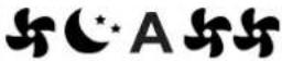 |
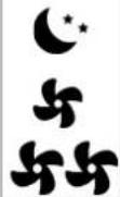 | ||
3.6 Heating/cooling operation modes setting
| Key Operation Display | ||
| [w8CG] | Keep the Heating / Cooling key pressed for approx. 2 seconds to change the mode between heating and cooling, which is indicated by the 2 symbols that appear if heating or cooling is active. |  |
| When heating, the symbol displays when the set point is higher than ambient temperature, both are off when the set point is lower. |  | |
| When cooling, the symbol displays when the set point is lower than ambient temperature, both are off when the set point is higher. |  | |
3.7 Stand By
| Key Operation Display | ||
| Press and hold the ON Stand-By key for approx. 2 seconds. No illuminated signals on the display at all means that the system is in stand-by (no operation). | Off | |
When the control is in this operating mode, anti freezing is in any case guaranteed. If the ambient temperature drops
below 5°C, the solenoid valves on the hot water output and the boiler are opened.
3.8 Temperature selection
| Key Operation Display | ||
 | Set the required room temperature using the two increase/decrease keys to set the temperature value on the 3-digit display. | 20.5 |
The adjustment range is from 16 to 28°C in intervals of 0.5°C, but out-of-range values are also accepted, from 5°C to 40°C (unless in auto mode).
Only set these values for brief periods, and then set a intermediate value.
The controller is very precise - set it to the required value and wait for the controller to regulate itself according to the actual room temperature detected.
3.9 Automatic operation
| Key Operation Display | ||
| AUTO | Press and hold the AUTO key. The function being activated is indicated by the relevant symbol appearing on the display. | A |
Ventilation speed adjustment is carried out automatically between the minimum and maximum values, according to
the distance of the actual room temperature from the set point, according to a PI-type algorithm.
3.10 Silent operation
| Key Operation Display | ||
| Press and hold the Silent key. The function being activated is indicated by the relevant symbol appearing on the display. | ||
Ventilation speed is limited to a contained maximum value.
3.11 Night-time operation
| Key Operation Display | ||
| Press and hold the Night-time operation key. The function being activated is indicated by the relevant symbol appearing on the display. | ||
By selecting this mode, ventilation speed is limited to a very contained level and the set temperature is adjusted automatically, as follows:
- decreases by 1° C after one hour and by another degree after two hours in heating mode;
- increases by 1° C after one hour and by another degree after two hours in cooling mode;
3.12 Operation at maximum ventilation speed
| Key Operation Display | |
| Press and hold the Max Operation key. The function being activated is indicated by the relevant symbol appearing on the display. |
In this operation mode, the maximum possible power level is activated whether heating or cooling.
Once the desired room temperature is reached, we recommend selecting one of the other 3 operation modes for increased comfort and sound levels.
3.13 Key lock
| Key Operation Display | ||
| + | By pressing both the + and - keys for 3 seconds, all keys are locked locally, and this is indicated by "bL" appearing on the display. | bL |
| - | All actions are disabled to the user and whenever any key is pressed, "LOC" will appear. To unlock the keys, repeat the sequence. | |
3.14 Reduce brightness to minimum
After 20 seconds from the last action, the panel brightness will be reduced for improved night-time comfort, and the room temperature will appear on the display.
If this brightness is still disturbing, the display can be switched off completely.
| Key Operation Display | ||
| + | With the display off, press and hold the + key for 5 seconds until "01" is displayed.Use the - key to change the value to 00 and wait 20 seconds to check the setting has been accepted. | 00 |
3.15 Deactivation
| Key Operation Display | ||
| Press and hold the ON Stand-By key for approx. 2 seconds. No illuminated signals on the display at all means that the system is in stand-by (no operation). | Off | |
The controller also ensures anti freezing when in stand-by.
3.16 Room temperature probe regulation offset
As the detection probe is towards the bottom of the device, the temperature detected may at times differ from the actual room temperature.
By using this function, the value displayed can be adjusted in a range from -9 to +12 K in intervals of 0.1°C.
Use this adjustment with care, and only after having actually detected a discrepancy compared with the actual room temperature using a reliable device!
| Key Operation Display | ||
| — | With the display off, press and hold the - key for 5 seconds to access the menu which allows adjustment (using the + and - keys) of the AIR probe offset displayed, from -9 to +12 K in 0.1 K intervals.After 20 seconds from the last action, the panel switches off and the setting is stored. | 00.0 |
3.17 Switching off for long periods
When switching off for a season or for holidays, proceed as follows:
- Deactivate the device
⚠ The antifreeze function is not active.
3.18 Error signals
| Error Display | |
| Room temperature probe fault (on the thermostat). |   |
| Fault or connection of a double remote room probe on board one of the fan coil units connected. |   |
EKRTCTRL2
4.1 SMART TOUCH electronic control panel with fixed speed modulation
These controls make room temperature adjustment (with offset settable from the keyboard) completely autonomous through the four speeds by means of a probe located in the lower part of the device, ensuring anti-freeze safety even when set to stand-by.
The control panel has a memory, so settings will not be lost if the appliance is switched off or in the power supply is cut.
After 20 seconds from the last action the panel brightness will be reduced for improved night-time comfort, and the room temperature will appear on the display. Press any key to restore maximum brightness.
The 10 kΩ water temperature probe positioned in the device battery regulations the minimum level when heating (30°C) and the maximum level when cooling (20°C).
Controls cannot be installed on the FWXM-series.
| A Display | |
| B Keys |

4.2 Display
Any statuses and alarms are also shown on the display by using 8 specific symbols:
| A | Automatic operation in steps |
| Minimum operation | |
| Maximum ventilation speed | |
| Super silent operation | |
| Heating on |
| Cooling on | |
| Supervision active (flashing light) | |
| Alarm indicator (solid light) | |
| Panel off indicator | |
| Resistance active indicator |
4.3 Key function
The various functions are set using 8 backlit keys:
| + | Temp + is for increasing the set temperature by 1 K |
| - | Temp - is for decreasing the set temperature by 1 K |
| Heating / Cooling: for changing the operation mode between heating and cooling | |
| AUTO | In automatic mode, the fan carries out a "stepped" adjustment to move the room temperature closer to the set point. |
| The super silent setting activates powerful dehumidifying when cooling and only radiation when heating. | |
| Maximum speed operation: Allows for the maximum ventilation speed to be set | |
| ON/Stand-By: for activating the device or for putting it in stand-by. | |
| Minimum: limits ventilation speed to a very contained value |
4.4 General On Switch
In order to manage the device via the control panel, this must be connected to the mains electricity. If a general switch is installed on the power line, this must
also be switched on.
- Turn the device on by activating the general switch
4.5 Activation
To activate the device
| Key Operation Display | ||
 | Press the ON Stand-by key From off to on | |
 | Select one of the four speeds by pressing the relevant key. |  |
 | ||
4.6 Heating/cooling operation modes setting
| Key Operation Display | ||
 | Keep the Heating / Cooling key pressed for approx. 2 seconds to change the mode between heating and cooling, which is indicated by the 2 symbols that appear if heating or cooling is active. |  |
| When heating, the symbol displays when the set point is higher than ambient temperature, both are off when the set point is lower. |  | |
| When cooling, the symbol displays when the set point is lower than ambient temperature, both are off when the set point is higher. |  | |
One of the two symbols flashing means that the water temperature (hot or cold) is not sufficient, and stops the fan until the temperature reaches a level suitable for reaching the required temperature. If after switching the power on the board detects the
H2 probe, start-up occurs in normal conditions with the minimum and maximum thresholds. The board also has a function when there is no H2 probe, in such cases the fan stop thresholds are ignored.
4.7 Stand By
| Key Operation Display | ||
| [6GZZ] | Press and hold the ON Stand-By key for approx. 2 seconds. No illuminated signals on the display at all means that the system is in stand-by (no operation). | From on to off |
When the control is in this operating mode, anti freezing is in any case guaranteed. If the ambient temperature drops
below 5° C, the solinoid output is opened.
4.8 Temperature selection
| Key Operation Display | ||
 | Set the required room temperature using the two increase/decrease keys to set the temperature value on the 3-digit display. |  |
The adjustment range is from 16 to 28°C in intervals of 1°C, but out-of-range values are also accepted, from 5°C to 40°C (unless in auto mode).
Only set these values for brief periods, and then set a intermediate value.
4.9 Ventilation speed regulation
| Key Operation Display | ||
 | The fan speed is selected by using one of the 4 keys (automatic, minimum, super silent and maximum). The activation of the function is indicated by the relevant symbol on the display. | |
 | ||
 | ||
 | ||
In automatic mode, the fan carries out a "stepped" adjustment to move the room temperature closer to the set point.
The super silent setting activates powerful dehumidifying when cooling and only radiation (with the fan off, solenoid valve, and in the RS version, microfans activated) when heating.
By setting the highest speed, the maximum possible power level is activated immediately whether heating or cooling.
Once the desired room temperature is reached, we recommend selecting one of the other 3 operation modes for increased comfort and sound levels.
In "minimum" mode, the number of fan revolutions is limited both when heating and cooling.
4.10 Key lock
| Key Operation Display | ||
| + | By pressing both the + and - keys for 3 seconds, all keys are locked locally, and this is indicated by "bL" appearing on the display. | bL |
| - | All actions are disabled to the user and whenever any key is pressed, "LOC" will appear. To unlock the keys, repeat the sequence. | |
4.11 Reduce brightness to minimum
After 20 seconds from the last action, the panel brightness will be reduced for improved night-time comfort, and the room temperature will appear on the display.
If this brightness is still disturbing, the display can be
switched off completely.
| Key Operation Display | ||
| + | With the display off, press and hold the + key for 5 seconds until "01" is displayed. Use the - key to change the value to 00 and wait 20 seconds to check the setting has been accepted. | 00 |
| Key Operation Display | ||
| + | With the display off, press and hold the + key for 5 seconds until "01" is displayed.Use the - key to change the value to 00 and wait 20 seconds to check the setting has been accepted. | 00 |
4.12 Deactivation
| Key Operation Display | ||
| Press and hold the ON Stand-By key for approx. 2 seconds. No illuminated signals on the display at all means that the system is in stand-by (no operation). | From on to off | |
The controller also ensures anti freezing when in stand-by.
4.13 Room temperature probe regulation offset
As the detection probe is towards the bottom of the device, the temperature detected may at times differ from the actual room temperature.
By using this function, the value displayed can be adjusted in a range from -9 to +12 K in intervals of 1° C.
Use this adjustment with caro, and only after having actually detected a discrepancy compared with the actual room temperature using a reliable device!
| Key Operation Display | ||
| — | With the display off, press and hold the - key for 5 seconds to access the menu which allows adjustment (using the + and - keys) of the AIR probe offset displayed, from -9 to +12 K in 1 K intervals.After 20 seconds from the last action, the panel switches off and the setting is stored. | 00 |
4.14 Switching off for long periods
When switching off for a season or for holidays, proceed as follows:
- Deactivate the device
- Turn the general unit switch to off.
⚠ The antifreeze function is not active.
4.15 Error signals
| Error Display | |
| Faulty room temperature (AIR) probe |  |
| Problem with fan motor (e.g. blockage caused by foreign objects, faulty rotation sensor). |  |
| Water temperature probe fault.In this case, ensure that the probe installed is 10 kΩ. |  |
| Engaging of grille microswitch S1 due to filter cleaning operation |  |
EKPCBO
5.1 On-board speed selector for connecting to standard thermostat
The command is for switching on and off and selecting the 4 speeds directly from the fan coil.
Switching on and off takes place via closing of the external thermostat contact.
The control panel has a memory, so settings will not be lost if the appliance is switched off or in the power supply is cut.
Controls cannot be installed on the FWXM-series.
After 20 seconds from the last action, the LED brightness will be reduced for improved night-time comfort. Press any key to restore maximum brightness.
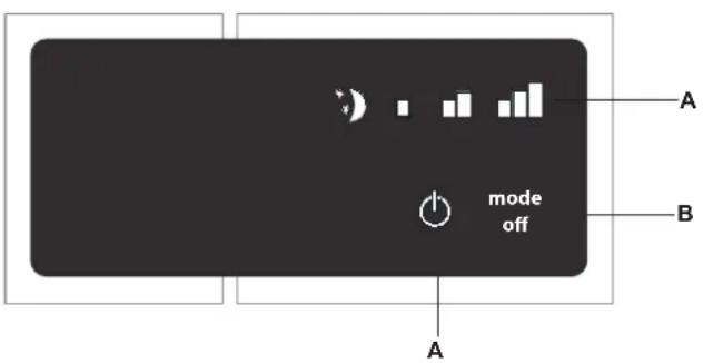
| A | Warning Lod |
| B | speed selection key |
5.2 LED indications
The 5 LEDs display the operational states:
| Minimum speed selected | |
| Medium speed selected | |
| Maximum speed selected |
| * *) | Supersilent function selected |
| Fan coil off or TA contact open (flashing) | |
5.3 General On Switch
To manage the fan coil via the selector, it must be connected to the mains and to a room thermostat with a single 230V AC contact.
If a general switch is installed on the power line, this must also be switched on.
- Turn the device on by activating the general switch
5.4 Activation
To activate the device
| Key Operation Display | ||
| mode off | Press the mode/off key Off → On | |
| mode off | Select one of the 4 operating speeds by pressing the relative mode/off key. If the red symbol is flashing, it means that the room thermostat is not connected; it therefore needs to be activated. | |
5.5 Stand By
| Key Operation Display | ||
| mode off | Press and hold the mode/off key for approx. 2 seconds. No illuminated signals on the display at all means that the system is in stand-by (no operation). | Off → On |
5.6 Ventilation speed regulation
| Key Operation Display | ||
| mode off | Each time the mode/off button is pressed the fan speed moves between supersilent, minimum, medium and maximum.The function being activated is indicated by the relevant symbol appearing on the display. | * ) ■ ■ ■ |
By setting the highest speed, the maximum possible power level is activated immediately whether heating or cooling.
Once the desired room temperature is reached, we recommend selecting one of the other 3 operation modes for increased comfort and sound levels.
5.7 Deactivation
| Key Operation Display | ||
| mode off | Press and hold the mode/off key for approx. 2 seconds. No illuminated signals on the display at all means that the system is in stand-by (no operation). | Off |
5.8 Switching off for long periods
When switching off for a season or for holidays, proceed as follows:
- Deactivate the device
- Turn the general unit switch to off.
5.9 Error status warnings
The board provides diagnostics in the event of anomalies, which can be interpreted from combinations of LEDs. The following table summarises the warnings.
- Flashing LED : TERM contact open
- Flashing LED : TERM contact closed;
• 4 flashing LEDs: GRID contact open;
• LED on: supersilent speed active (400 rpm).
• LID on: minimum speed active (680 rpm).
• Llon: medium speed active (1,100 rpm).
• Litter: maximum speed active (1,500 rpm).
MAINTENANCE
6.1 External cleaning
Before every cleaning and maintenance intervention, disconnect the appliance from the mains by switching off the master switch.
⚠️ Wait until the parts have cooled down to avoid the risk of burns.
Do not use abrasive sponges or abrasive or corrosive detergents to avoid damaging the painted surfaces.
When necessary, clean the outer surfaces of the heat pump convector with a soft damp cloth.

6.2 Cleaning air suction filter
After a period of continuous operation and in consideration of the concentration of impurities in the air, or when he
intends to restart the plant after a period of inactivity, proceed as described.
Extraction of filter cells
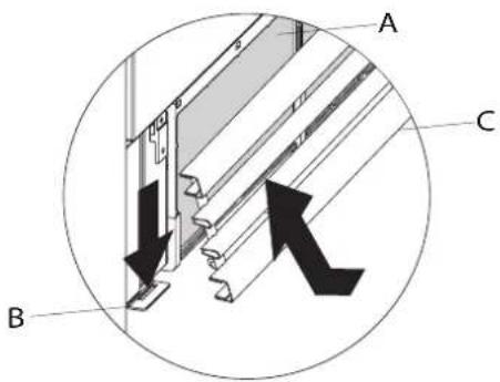
To remove the grill:
- lift the grill until it is completely released from the seat
- lit the grill and slide it outwards
- then remove the filter by pulling it outwards
A Front grill
B Grill hook
C Filter

Cleaning filtering seats
- suck up the powder with a vacuum cleaner
- wash the filter with running water without using detergents or solvents, and leave to dry.
It is forbidden to use the unit without the net filters.
The appliance is fitted with a safety switch that prevents the operation of the cooler with the mobile panel missing or out of position.
After finishing the cleaning of the filter, check that the panel is mounted correctly.

Ending Cleaning Operations
- For the versions with a grill with flaps, insert the two lugs into the special slots, turn it and hook it up with a slight tap on the upper part.
A Filter
B Grill hook
C Front grill
D The filter housing


6.3 Energy saving tips
- Always keep the filters clean;
- when far possible, keep the doors and windows closed in the room being conditioned;
- limit where possible the effect of direct sun rays in the rooms being conditioned (uso curtains, shutters etc.)
TROUBLESHOOTING
7.4 Troubleshooting
In the event of water leaks or anomalous operation, disconnect mains power immediately and close all water taps.
⚠️ If one of the following anomalies should occur, contact an authorised service centre or qualified personnel, do not try to repair yourself.
- Ventilation does not start even if there is hot or cold water in the hydraulic circuit.
- The device leaks water when heating.
- The device leaks water only when cooling.
- The device makes excessive noise.
- Rust is forming on the front panel.
7.5 Troubleshooting table
Maintenance must be carried out by a qualified installer or by a specialised service centre.
| Effect Cause Solution | ||
| Ventilation takes a long time to start when new temperature settings or anew mode is activated. | The circuit valve needs time to open and to let cold or hot water circulate. | Wait 2 or 3 minutes for the circuit valve to open. |
| The device doesn't start ventilating. No hot or cold water in the system. | Check that the boiler or the water cooler are working. | |
| Ventilation does not start even if there is hot or cold water in the hydraulic circuit. | The hydraulic valve stays closed. | Disassemble the valve body and check and restore water circulation. |
| Check that the valve is working by powering it up separately from a 230V supply. If it starts working, the problem may be with the electronic controller. | ||
| The fan motor is blocked or burned out. | Check the motor windings and that the fan can turn freely. | |
| The microswitch that stops ventilation when opening the filter grill doesn't close properly. | Check that closing the grill closes the contact on the microswitch. | |
| Electrical connections are incorrect. Check the electrical connections. | ||
| The device leaks water when heating. | Water leakage from the system plumbing. | Check for leaks and tighten all connections. |
| Loaks from the valve group. Check the scales. | ||
| Rust is forming on the front panel. Thermal isolators detached. | Check that the thermal sound isolators are positioned correctly, paying particular attention to the one positioned at the front above the winged battery. | |
| Water droplets are forming on the grill and the air outlet. | In high relative ambient humidity (>60%), condensation may occur, especially when the fan is at its minimum speed. | As soon as relative humidity decreases, the problem will disappear. In any case, should some water droplets fall inside the units, it does not mean that there is a malfunction. |
| The device leaks water only when cooling. | The condensation tank is blocked. | Slowly pour a bottle of water in the lower part of the battery to check drainage; if required, clean the tank and/or improve the incline of the drain tube. |
| The condensation drain does not have sufficient incline to drain. | ||
| The connection pipes and valve group are not well isolated. | Check pipe insulation. | |
| The device makes excessive noise. | The fan is touching the structure. | Check for dirt in filters and if necessary, clean them. |
| The fan is unbalanced. | An unbalanced fan causes excessive vibrations in the machine: replace the fan. | |
| Check for dirt in filters and if necessary, clean them. | Clean the filters. | |
- COMPLIANCE
- SYMBOLS
- EDITORIAL PICTOGRAMS
- U USER
- 1 INSTALLER
- SERVICE
- SAFETY PICTOGRAMS
- WARNING
- DANGEROUS ELECTRICAL CURRENT
- HIGH TEMPERATURE DANGER
- PROHIBITION
- 1 GENERAL
- 2 EKRTCTRL1
- 3 EKWHCTRL1
- 4 EKRTCTRL2
- 5 EKPCBO
- 6 MAINTENANCE
- 7 TROUBLESHOOTING
- GENERAL
- 1.1 GENERAL WAENINGS
- 1.2 FUNDAMENTAL SAFETY RULES
- EKRTCTRL1
- 2.1 SMART TOUCH ELECTRONIC CONTROL PANEL WITH DEVICE SIDE CONTINUOUS MODULATION
- 2.2 DISPLAY
- 2.3 KEY FUNCTION
- 2.4 GENERAL ON SWITCH
- 2.5 ACTIVATION
- 2.6 HEATING/COOLING OPERATION MODES SETTING
- 2.7 STAND BY
- 2.8 TEMPERATURE SELECTION
- 2.9 AUTOMATIC OPERATION
- 2.10 SILENT OPERATION
- 2.11 NIGHT-TIME OPERATION
- 2.12 OPERATION AT MAXIMUM VENTILATION SPEED
- 2.13 KEY LOCK
- 2.14 REDUCE BRIGHTNESS TO MINIMUM
- 2.15 DEACTIVATION
- 2.16 ROOM TEMPERATURE PROBE REGULATION OFFSET
- 2.17 SWITCHING OFF FOR LONG PERIODS
- 2.18 ERROR SIGNALS
- EKWHCTRL1
- 3.1 WALL-MOUNTED SMART TOUCH ELECTRONIC CONTROL PANEL WITH ROOM PROBE
- 3.2 DISPLAY
- 3.3 KEY FUNCTION
- 3.4 GENERAL ON SWITCH
- 3.5 ACTIVATION
- 3.9 AUTOMATIC OPERATION
- 3.10 SILENT OPERATION
- 3.11 NIGHT-TIME OPERATION
- 3.12 OPERATION AT MAXIMUM VENTILATION SPEED
- 3.13 KEY LOCK
- 3.14 REDUCE BRIGHTNESS TO MINIMUM
- 3.16 ROOM TEMPERATURE PROBE REGULATION OFFSET
- 3.17 SWITCHING OFF FOR LONG PERIODS
- EKRTCTRL2
- 4.1 SMART TOUCH ELECTRONIC CONTROL PANEL WITH FIXED SPEED MODULATION
- 4.2 DISPLAY
- 4.3 KEY FUNCTION
- 4.4 GENERAL ON SWITCH
- 4.5 ACTIVATION
- 4.6 HEATING/COOLING OPERATION MODES SETTING
- 4.7 STAND BY
- 4.8 TEMPERATURE SELECTION
- 4.9 VENTILATION SPEED REGULATION
- 4.10 KEY LOCK
- 4.11 REDUCE BRIGHTNESS TO MINIMUM
- 4.12 DEACTIVATION
- 4.13 ROOM TEMPERATURE PROBE REGULATION OFFSET
- 4.14 SWITCHING OFF FOR LONG PERIODS
- 4.15 ERROR SIGNALS
- EKPCBO
- 5.1 ON-BOARD SPEED SELECTOR FOR CONNECTING TO STANDARD THERMOSTAT
- 5.2 LED INDICATIONS
- 5.3 GENERAL ON SWITCH
- 5.4 ACTIVATION
- 5.5 STAND BY
- 5.6 VENTILATION SPEED REGULATION
- 5.7 DEACTIVATION
- 5.8 SWITCHING OFF FOR LONG PERIODS
- 5.9 ERROR STATUS WARNINGS
- MAINTENANCE
- 6.1 EXTERNAL CLEANING
- 6.2 CLEANING AIR SUCTION FILTER
- EXTRACTION OF FILTER CELLS
- CLEANING FILTERING SEATS
- ENDING CLEANING OPERATIONS
- 6.3 ENERGY SAVING TIPS
- TROUBLESHOOTING
- 7.4 TROUBLESHOOTING
- 7.5 TROUBLESHOOTING TABLE
Brand : DAIKIN
Model : EKWHCTRL0
Category : Thermostat